hydraulics branch official file copy … · 5. vortices formed near the forebay headwall with the...
TRANSCRIPT
HYDRAULICS BRANCH OFFICIAL FILE COPY
UNITED STATES DEPARTMENT OF THE INTERIOR
BUREAU OF RECLAMATION
MODEL STUDIES OF SUCTION TUBES FOR MILE 1 8 AND FORE BAY PUMPING PLANTS SAN LUIS UNIT--CENTRAL VALLEY PROJECT
CALIFORNIA
Hydraulics Branch Report No. Hyd-51 3
DIVISION OF RESEARCH
OFFICE OF CHIEF ENGINEER DENVER, COLORADO
June 2 8, 19 6 3
The information contained in this report may not be used in any publication, advertising, or other promotion in such a manner as to constitute an endorsement by the Government or the Bureau of Reclamation, either explicit or implicit, of any material, product, device, or process that may be referred to in the report.
CONTENTS
Purpose ........................................... . Conclusions ................................... · ...... -Acknowledgment ....... ·· .•.. -................. · · .. _ ...... . Introduction . . . . . . . . . . . . . . . . . . . . . . . . . . . . . . . . . . . . . ... . The Model .................... ·· ....................... .
Facilities ..... •, .......................... • ....... . Instrumentation .................................... .
Investigation ...................................... .
Vortex Elimination ..•.....•...................... Velocity Traverses and Flow Studies ..........•.... Loss Measu:rements .....•.........•.........•.... Elbpws Calibrated as Flowmeters •.•......•........ Self-cleaning Characteristics ..•..........•...•..••
Page
l 1 2 3 4
4 5
6
7 8 9
10 10
Table
Loss Coefficients for Suction Tube . . • . • . . . . . . . • . . • . . . • 1
APPENDIX
Page
Sample Calculations of Velocity Traverse Data . . . . . . . . . 15
Figure
Location Map .................. _, . . . . . . . . . . . . . . . . . . . . 1 Suction Tube with 't, R Constant Elbow . . • . . . . . . . . . • • • . 2 RV Constant Suction Elbow . . . . . . . . . . • . • . . . . . . . . . . • . . . 3 Plastic Elbows . . . . . . . . . . . . . . . . . . . . . . . . . . . . . . . . . . . . . 4 Model Details . . . . . . . . • . • . . . • . . . . . . . . . . . . . . . . . . . . . . . 5 Views of Hydraulic Model . . • . . . . • . . . . . . . . . . . . . . . . . . . . 6 Calibration Curve for Van der Hegge Sphere . . . . . . . . . . . 7 Vortex Action with Initial Forebay Design . . . . . . . . . . . • . 8 Effect of Trashrack and Pier Extensions
on Vortex Action . . . . . • . . . . . . . • . . . . . . . . . . . . . . . • . • . . 9 Effect of Hood on Vortex Action and Flow in
Suction Tube at Pump Eye .•.•...............•...•.• Effects of Elliptical Pier Noses and Pier
10
Perforations . . . . . . . . . . . . . . . . . . . . . . . . . . . . . . . . . . . . . . 11
CONTENT$- -Continued
Velocity Contours at Station A-B for the <t, R Constant Suction Tube ....................•......•..
Velocity Contours at Station A-B for the RV Constant Suction Tube ......................•...•.•.
Intermediate Velocity Traverses, and Pressure Differential vs Discharge Curves .......•.......•....
Size of Gravel and Rock that Flow Will Sweep from Suction Tube ................................ .
Figure
12
13
14
15
. UNITED STATES . DEPARTMENT OF THE INTERiOR
BUREAU OF RECLAMATION
Office of Chief Engineer Division of Research · Hydraulics Branch Denver, Colorado June 28, 1963
Hydraulics Branch Report No. Hyd-513
Compiled by: T. J. Isbester Checked by: W. P. Simmons Reviewed by: W. E. Wagner Submitted by: H. M. Martin
Subject: Model studies of suction tubes for Mile 18 arid Forebay Pumping Pla.nts--San Luis Unit--Central Valley Project, California
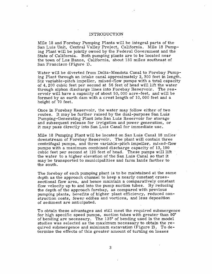
PURPOSE
Model studies were conducted on a suction tube using two different 135° elbows to determine the more satisfactory elbow design for large pumps requiring appreciable submergence and using shallow forebays, and to determine loss and flow pattern characteristics at the impeller inlet. Although the model studies were conducted primarily to establish designs for Forebay and Mile 18 Pumping Plants, the results also establish design criteria for suction tubes
· of future large pumping plants.
CONCLUSIONS
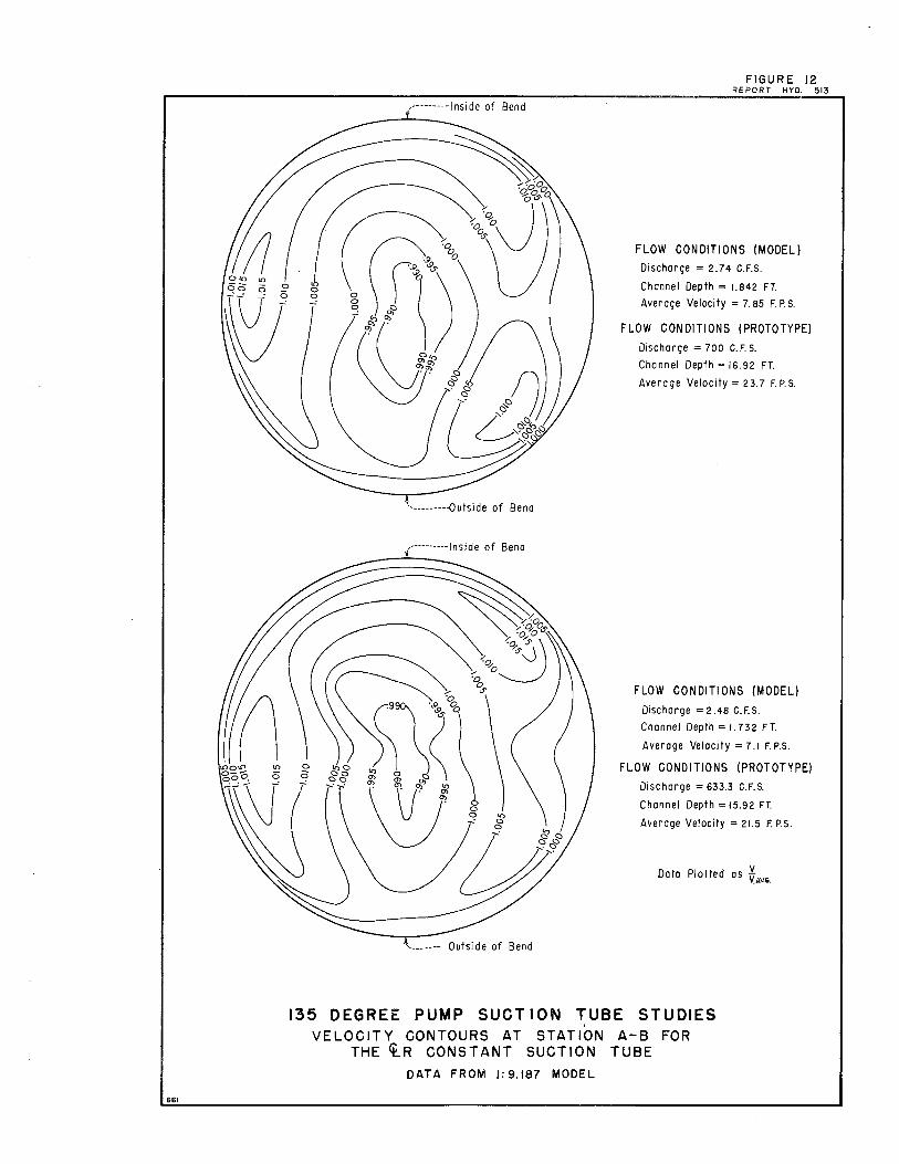
1. Comparatively uniform velocity distribution resulted at the pump eye (impeller inlet) with both the constant-radius-centerline (~ R constant) and the constant-radius-velocity (RV constant) elbow designs (Figures 12 and 13). ·
2. The flow moved smoothly and steadily through all parts of the suction tubes with either the ~ R constant or the RV constant elbows installed. There were no zones .of separation, no adverse eddy patterns, and no detrimental swirling or spiraling flow.
3. The head loss for. the suction tube with the 'I, R constant elbow installed was 0. 075 times the velocity head at .the pump eye without· the hood in the forebay, and O. 060 times the pump eye velocity head with the hood installed. The hood is discussed subsequently.
4. The head loss for the suction tube with the RV constant elbow installed was 0. 065 times the pump eye velocity head without the hood in the forebay.

5. Vortices formed near the forebay headwall with the initial inlet design consisting of a vertical headwall with an elliptical transition to the suction tube crown (Figures 8 and 2A). The direction of rotation of the vortices was counterclockwise on the right of the center pier, and clockwise on the left of the center pier. The piers are viewed looking downstream.
6. Vortex action could be reduced by increasing the lengths of the side piers, and maintaining a short center pier (Figure 9B).
7. Trashracks installed in the forebay upstream of the piers had no visible effect on vortex action (Figure 9A).
8. Perforations in the side piers produced no visible effect on vortex action.
9. Although use of elliptical pier noses in the forebay provided better flow conditions to the inlet transition, they had no visible effect on vortex action.
10. A hood, produced by extending the slope of the roof from Station 18 upward along a straight line to a point above the maximum water surface, eliminated the dead water space at the headwall and was effective in eliminating detrimental vortices (Figures 2B and l0A).
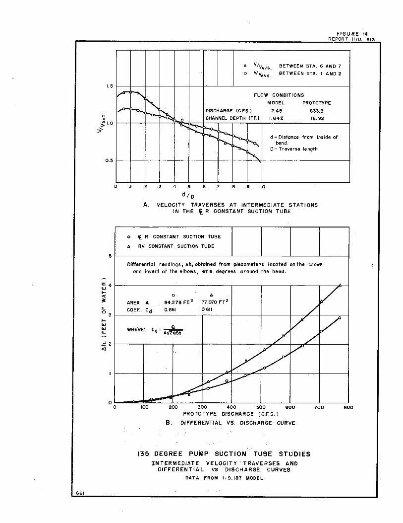
11. The suction tube was calibrated as a flowmeter with each elbow design (Figure 14B). Differential pressures were measured 67-1/2° along the bend on the crown and invert of the tube. (Figure 14B).
12. The self-cleaning characteristics of the suction tube with either elbow was excellent due to maintenance of an appreciable and continually increasing flow velocity in the tube (Figure 15).
ACKNOWLEDGMENT
The results achieved through this test program resulted from the cooperation of the Hydraulic Machinery Branch and the Hydraulics Branch of the Chief Engineer's Office in Denver. The data were obtained over a period of 6 months beginning in August 1962.
2
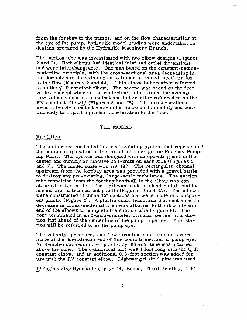
INTRODUCTION
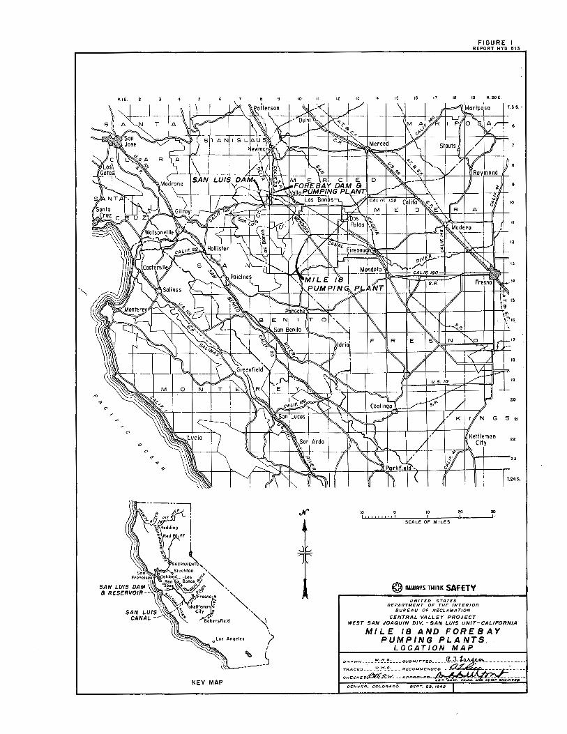
Mile 18 and Forebay Pumping Plants will be integral parts of the San Luis Unit, Central Valley Project, California. Mile 18 Pumping Plant willbe jointly owned by the Federal Government and the State of California. Both pumping plants are to be located near the town of Los Banos, California,· about 150 miles southeast of San Francisco (Figure 1).
Water will be diverted from Delta-Mendota Canal to Forebay Pumping Plant through an intake canal approximately 2, 300 feet in length. Six variable-pitch impeller, mixed-flow pumps with a total capacity of 4, 200 cubic feet per second at 56 feet of head will lift the water through siphon discharge lines into Forebay Reservoir. The reservoir will have a capacity of about 50,000 acre-feet, and will be formed by an earth dam with a crest length of 10,000 feet and a height of 70 feet.
Once in Forebay Reservoir, the water may follow either of two routes. It may be further raised by the dual-purpose San Luis Pumping-Generating Plant into San Luis Reservoir for storage and subsequent release for irrigation and power generation, or it may pass directly into San Luis Canal for immediate use.
Mile 18 Pumping Plant will be located on San Luis Canal 18 miles downstream of Forebay Reservoir. The plant will contain three centrifugal pumps, and three variable,-pitch impeller, mixed-flow pumps with a maximum combined discharge capacity of 13, 100 cubic feet per second.at 125 feet of head. These pumps will lift the water to a higher elevation of the San Luis Canal so that it may be transported to municipalities and farm lands farther to the south.
The forebay of each pumping plant is to be maintained at the same depth as the approach channel to keep a nearly constant crosssectional flow area, and hence maintain a comparatively constant flow velocity up to and into the pump suction tubes. By reducing the depth of the approach forebay, as compared with previous pumping plants, benefits of higher plant efficiency, reduced construction costs, fewer eddies and vortices, and less deposition of sediment are anticipated.
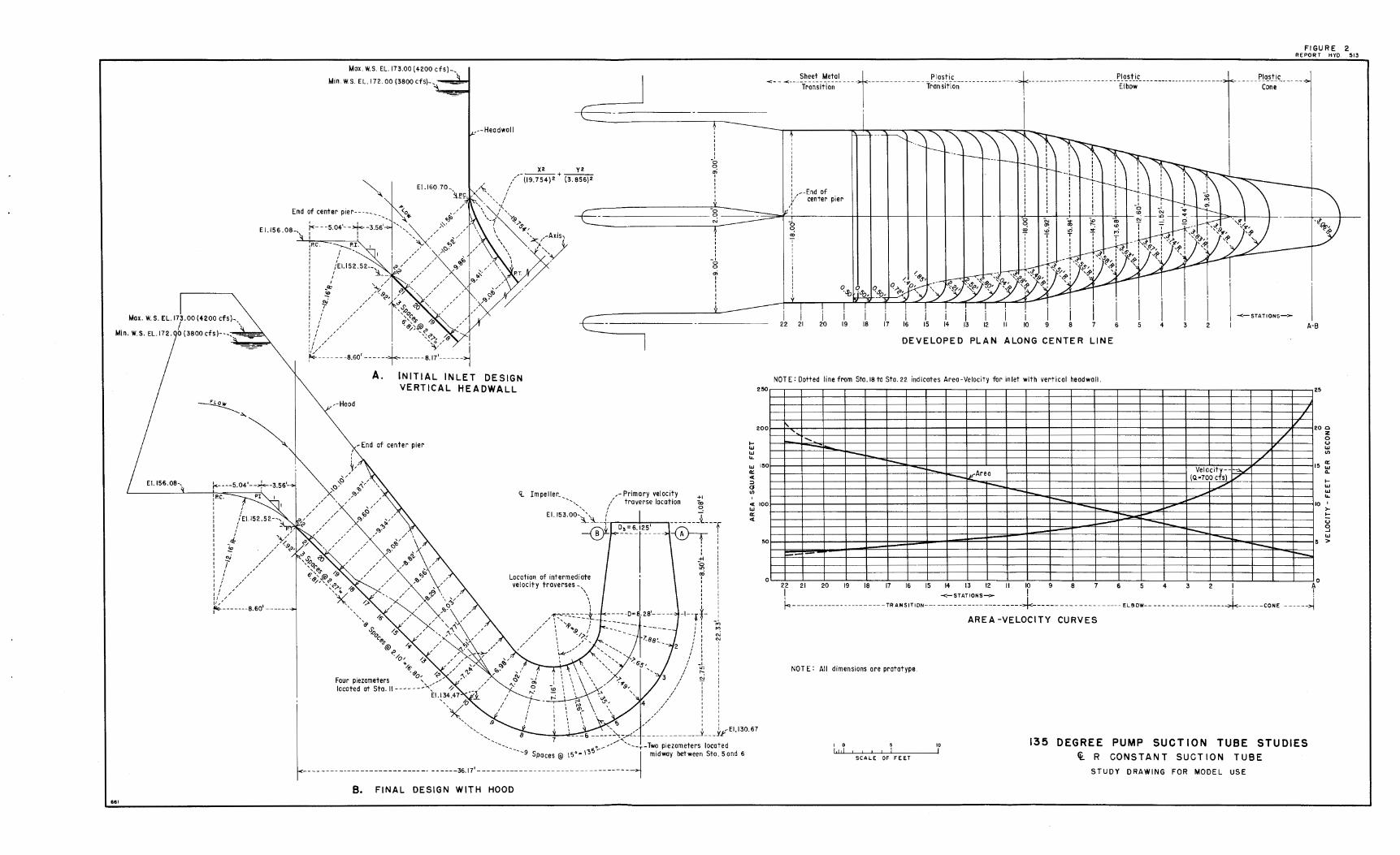
To obtain these advantages and still meet the required submergence for high specific speed pumps, suction tubes with greater than 90° of bending are necessary. The 135° of bending used in the model studies was selected as the maximum necessary to obtain the required submergence and minimum excavation (Figure 2) .. To determine the effects of this greater amount of turning on losses
3
from the forebay to the pumps. and on the fl.ow characteristics at the eye of the pump, hydraulic model studies were undertaken on designs prepared by the Hydraulic Machinery Branch.
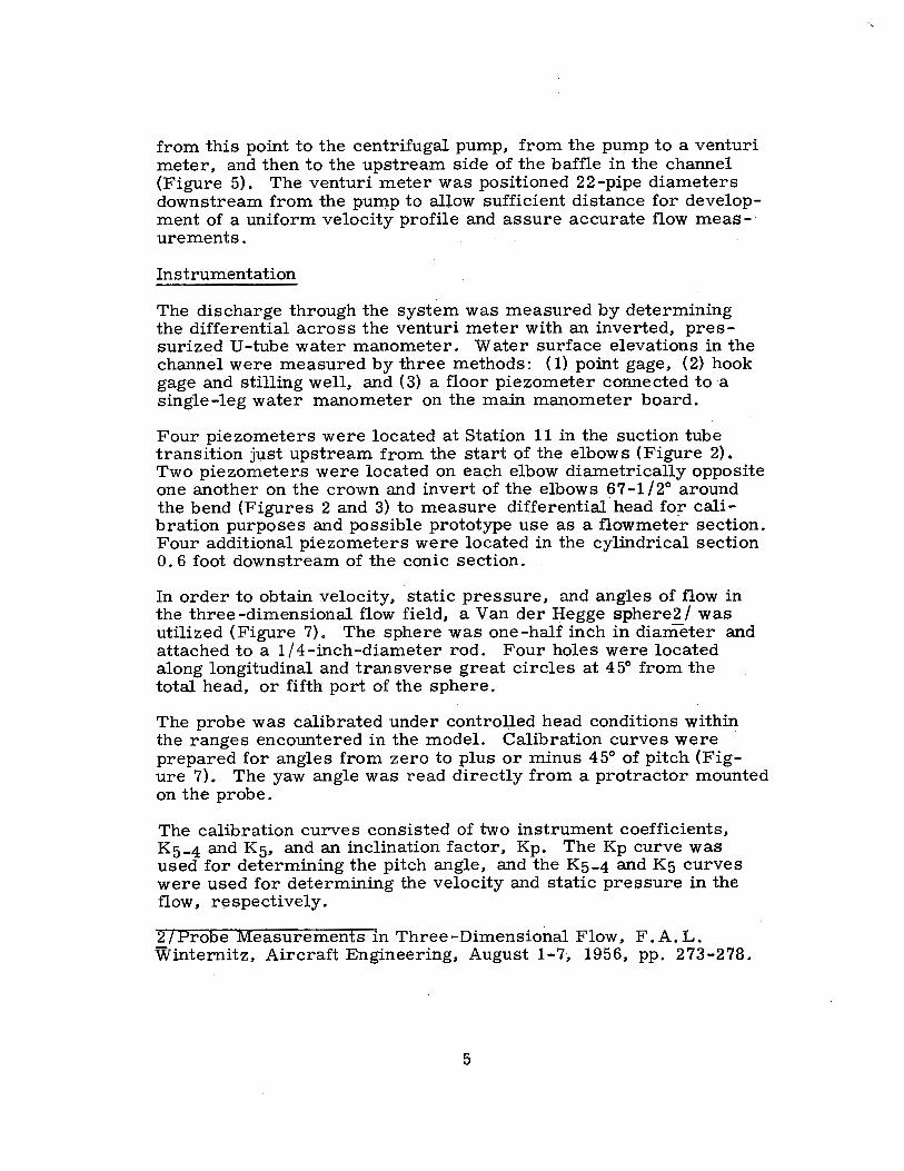
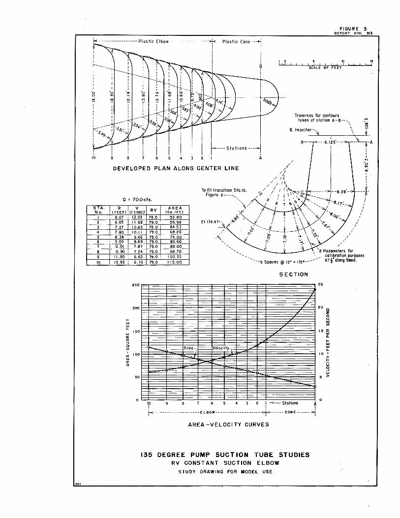
The suction tube was investigated with two elbow designs (Figures 2 and 3). Both elbows had identical inlet and outlet dimensions and were interchangeable. One was based on the constant-radiuscenterline principle, with the cross-sectional area decreasing in the downstream direction so as to impart a smooth acceleration to the fl.ow (Figures 2 and 4A). This elbow is hereafter referred to as the ~ R constant elbow. The second was based on the free vortex concept wherein the centerline radius times the average fl.ow velocity equals a constant and is hereafter referred to as the RV constant elbowl/ (Figures 3 and 4B). The cross-sectional area in the RV constant design also decreased smoothly and continuously to impart a gradual acceleration to the fl.ow.
THE MODEL
Facilities
The tests were conducted in a recirculating system that represented the basic configuration of the initial inlet design for Forebay Pumping Plant·. The system was designed with an operating unit in the center and dummy or inactive half-units on each side (Figures 5 and 6). The model scale was 1:9.187. The rectangular channel upstream from the forebay area was provided with a gravel baffle to destroy any pre-existing, large-scale turbulence. The suction tube transition from the forebay headwall to the elbow was constructed in two parts. The first was made of sheet metal, and the second w~s of transparent plastic (Figures 2 and 6A). The elbows were constructed in three 45° sections and were made of transparent plastic (Figure 4). A plastic conic transition that continued the decrease in cross -sectional area was attached to the downstream end of the elbows to complete the suction tube (Figure 6). The cone terminated in an 8-inch-diameter circular section at a sta-· tion just ahead of the centerline of the pump impeller. This station will be ref erred to as the pump eye.
The velocity. pressure, and fl.ow direction measurements were made at the downstream end of this conic transition or pump eye. An 8-inch-inside-diameter plastic cylindrical tube was attached above the cone. The cylindrical tube was 1 foot long with the Cf. R constant elbow. and an additional O. 3-foot section was added for use with the RV constant elbow. Lightweight steel pipe was used
!/Engineering Hydraulics, page 44, Rouse. Third Printing, 1961.
4
from this point to the centrifugal pump, from the pump to a venturi meter, and then to the upstream side of the baffle in the channel (Figure 5). The venturi meter was positioned 22-pipe diameters downstream from the pump to allow sufficient distance for development of a uniform velocity profile and assure accurate fl.ow meas-· urements.
Instrumentation
The discharge through the system was measured by determining the differential across the venturi meter with an inverted, pressurized U-tube water manometer. Water surface elevations in the channel were measured by three methods: ( 1) point gage, (2) hook gage and stilling well, and (3) a floor piezometer connected to a single-leg water manometer on the main manometer board.
Four piezometers were located at Station 11 in the suction tube transition just upstream from the start of the elbows (Figure 2). Two piezometers were located on each elbow diametrically opposite one another on the crown and invert of the elbows 67-1/2° around the bend (Figures 2 and 3) to measure differential head fo;r calibration purposes and possible prototype use as a flowmeter section. Four additional piezometers were located in the cylindrical section 0. 6 foot downstream of the conic section.
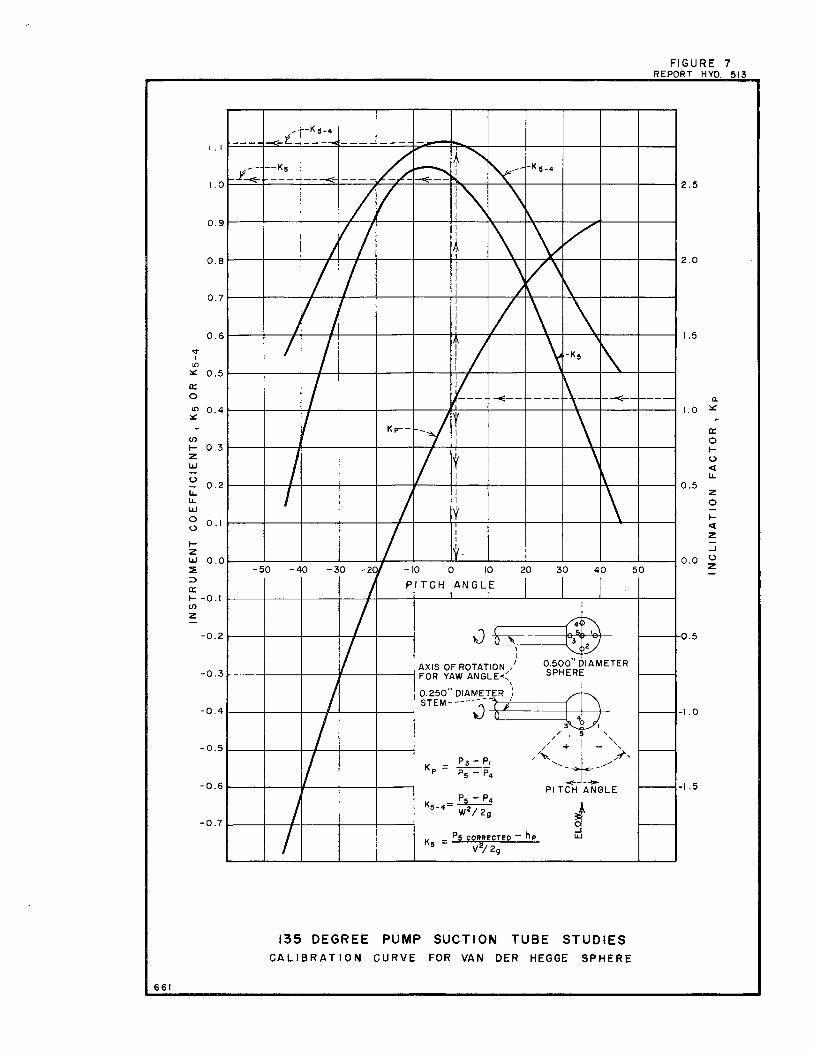
In order to obtain velocity, static pressure, and angles of flow in the three-dimensional flow field, a Van der Hegge sphere2/ was utilized (Figure 7). The sphere was one-half inch in diameter and attached to a 1/4-inch-diameter rod. Four holes were located along longitudinal and transverse great circles at 45° from the total head, or fifth. port of the sphere.
The probe was calibrated under controlled head conditions within the ranges encountered in the model. Calibration curves were · prepared for angles from zero to plus or minus 45° of pitch (Figure 7). The yaw angle was read directly from a protractor mounted on the probe.
The calibration curves consisted of two instrument coefficients, K5_4 and K5, and an inclination factor, Kp. The Kp curve was used for determining the pitch angle, and the Ks-4 and K5 curves were used for determining the velocity and static pressure in the flow, respectively.
2/Probe Measurements in Three-Dimensional Flow, F.A.L. Winternitz, Aircraft Engineering, August 1-7, 1956, pp. 273-278.
5
The probe was designed to avoid vibration due to vortex shedding, but not for mechanical vibration induced in the model by the pump and motor. No attempt was made to isolate the pump and motor from the system, and as a result, pump. vibrations transmitted to the plastic sections were picked up by the probe. These vibrations were not apparent unless the probe was inserted beyond the half traverse position (center of the test section). To obtain a complete traverse and avoid vibration in the probe, it was necessary to make two half traverses 180° apart. For each half traverse, the pumping conditions were matched as near as possible.
During the early phases of the test program, pressure cells were used in conjunction with the Sanborn recorder to measure the pressures acting on the Van der Hegge sphere. The pressure cell response was extremely sensitive .and rapid, so that with turbulent flow fluctuations in the streamline direction, the yaw pressures were almost impossible to balance. In the final test phases, long water manometer columns were employed to dampen the response, and make it easier to achieve an average balance for obtaining readings.
Also early in the test program, brass turning vanes were located in the cylindrical tube downstream from the conic section or pump eye to provide rotation to the flow similar to that imparted by a pump impeller. With vane deflections as high as 20°, no appreciable change in streamline direction or significant rotation to the flow was observed. However, an increase in pressure head was noted due to the vanes restricting the flow. To avoid the restriction, the vanes were removed, and were not used in the final testing phases.
As an additional check on the accuracy and reliability of the Van der Hegge sphere, a 1/4-inch-diameter 3-hole cylindrical probe was utilized. The probe was calibrated under controlled head conditions that included velocities encountered at the pump eye and at intermediate stations along the ~ R constant elbow (Figure 2).
INVESTIGATION
In the early phase of the test program, the system was checked at extreme conditiqns to detect any adverse effects, other than the vortex problem discussed below, which might occur in the prototype. The model pump capacity of 3. 25 cubic feet per second represented a prototype discharge of 831 cubic feet per second and allowed the system to be .investigated at a flow 18. 7 percent above the maximum for Forebay Pumping Plant. Channel depths were varied from a
6
maximum of 18. 37 feet (2-foot ·model) down to the lowest water surface attainable without drawing air into ·the elbow along the crown of the inlet transition. At a discharge of 700 cubic feet per second this minimum depth varied from 9; 19 feet (1-foot model) without the hood in the forebay, to 7.81 feet (0~85-foot model) with the hood·installed. These depths were considerably below the minimum channel depth of 15. 92 feet for Forebay Pumping Plant.
Vortex Elimination
The intermittent formation of vortices in the forebay caused considerable concern because air was drawn in through these vortices and carried into the suction tube .(Figures BA and BB). The vortices formed at discharges above 500 cubic feet per second at normal forebay depths, and were located near the forebay headwall on either side of the center pier. The direction of rotation for the vortices was counterclockwise on the right of the center pier, and clockwise on the left of the center pier;
The admission of air was of .concern for the following reason. The prototype pumps will discharge into long lines which terminate in siphon elbows that prevent backflow when the pumps are not running and provide minimum pumping head during normal operation. Any air admitted into the system will expand in the crown of the siphon where negative pressures exist. This air would decrease the effective flow area of the discharge lines and decrease the magnitude of the negative pressure at the siphon crown, and consequently increase the pumping head. · Large vacuum pumps would be needed to remove air accumulations from the siphon crowns and would have to operate almost continuously. It was desirable to avoid these air problems so modifications to change the flow patterns in the forebay were studied in an effort to eliminate the vortices.
Trashracks were. fabricated to scale and placed in position along the upstream face of the piers in an attempt to change the flow pattern between the piers in the forebay (Figure 9A). Velocities in the trashrack area were low and the longitudinal depth of the rack bars was small, resulting in very little, if any, modification to the flow pattern. Vortex action was not visibly changed by the trashracks.
A number of pier configurations was tested as possible solutions of the vortex problem. These modifications included varying the length of the piers, changing the pier nose shape, and perforating the piers between the active and inactive bays. The most effective combination of pier modifications consisted of a short center pier and long perforated side piers (Figure 9B). This configuration modified the . flow pattern sufficiently to greatly reduce the vortex action. However, to entirely eliminate the detrimental vortices a more effective solution was necessary.
7
A hood produced by extending the tangent slope of the roof of the suction tube transition at Station 18 upstream between the piers along a straight line to the top of the piers proved successful in eliminating detrimental vortex action (Figures 2B and lOA). The hood eliminated the dead water space at the forebay headwall and provided an effective means of guiding the flow into the suction tube inlet. As a secondary result, suction tube losses were slightly lowered (Table 1). Also, the hood provided a means of operating the system at lower forebay depths without the entrainment of air in the suction tube.
The effects of pier nose shape and pier perforations on the overall performance of the system were difficult to evaluate. Tests were made with dye, and with yarn attached to a small rod, to trace flow direction and detect backflow in the forebay area. These tests indicated that flow past the elliptical pier noses was smoother than flow past the chamfered pier noses at normal depths and discharges. Somewhat less backflow was also noted immediately downstream from the elliptical piers. This is clearly shown in Figure 1 lA with flow through one-half of the active bay and with the two pier nose shapes installed. The photograph, taken with canal water surface below designed depth and at half maximum discharge, or 350-cubicfeet-per-second prototype, substantiated the dye and yarn tests and provided a good representation of actual conditions, magnified only by significantly increased velocity.
The tests made for evaluating the perforated piers showed that flow through the perforations partially eliminated the differential head between active and inactive bays. but caused the relatively symetrical flow pattern (Figure 1 lA) to change to one with a strong cross flow (Figure 1 lB). As a result, regions of severe turbulence and backflow increased in size and extended farther into the suction tube inlet. The unsymmetrical pattern was considered undersirable and perforations are not recommended for these pumping plants. It should be noted that the photographs in Figures l lA and 1 lB were taken at the extreme conditions stated above to emphasize the flow patterns, and that conditions were similar but must less severe during normal operation.
Velocity Traverses and Flow Studies
Complete velocity traverses were obtained at Station A-B of the suction tube with the 'i, R constant and the RV constant elbows installed (Figures 2 and 3). These traverses were made in a horizontal plane at 45° increments to provide sufficient information to plot nondimensional velocity contour representations of the flow (Figures 12 and 13).
8
Tests were run at flows representillg the design discharges and at the maximum and minimum water surface elevations for Forebay Pumping Plant. These values were 700 · cubic feet per second at a forebay depth of 16. 92 feet and 633.3 ctlbic feet per second at a·forebay depth of 15. 92 feet.
Additional velocity traverses were made with a cylindrical probe at two intermediate locations· in the·~ R constant elbow (Figures 2 and 14A). These traverses indicated a flattening effect in the velocity profile in ·the downstream direction and substantiated the data obtained at Station A-B for this elbow.
Dyes, pieces of yarn, and streams of fine air bubbles were also used to trace the path of the flow. These tracers were introduced into the flow at various parts of the tube cross section at stations ranging from the forebay headwall to just past the downstream end of the elbows. In all cases the flow was shown to be moving smoothly and continuously downstream. No separation zones occurred; no adverse eddy patterns e~dsted; and no detrimental swirling took place. Flow conditions at the eye of the pump were relatively steady and well directed (Figure l0B).
Loss Measurements
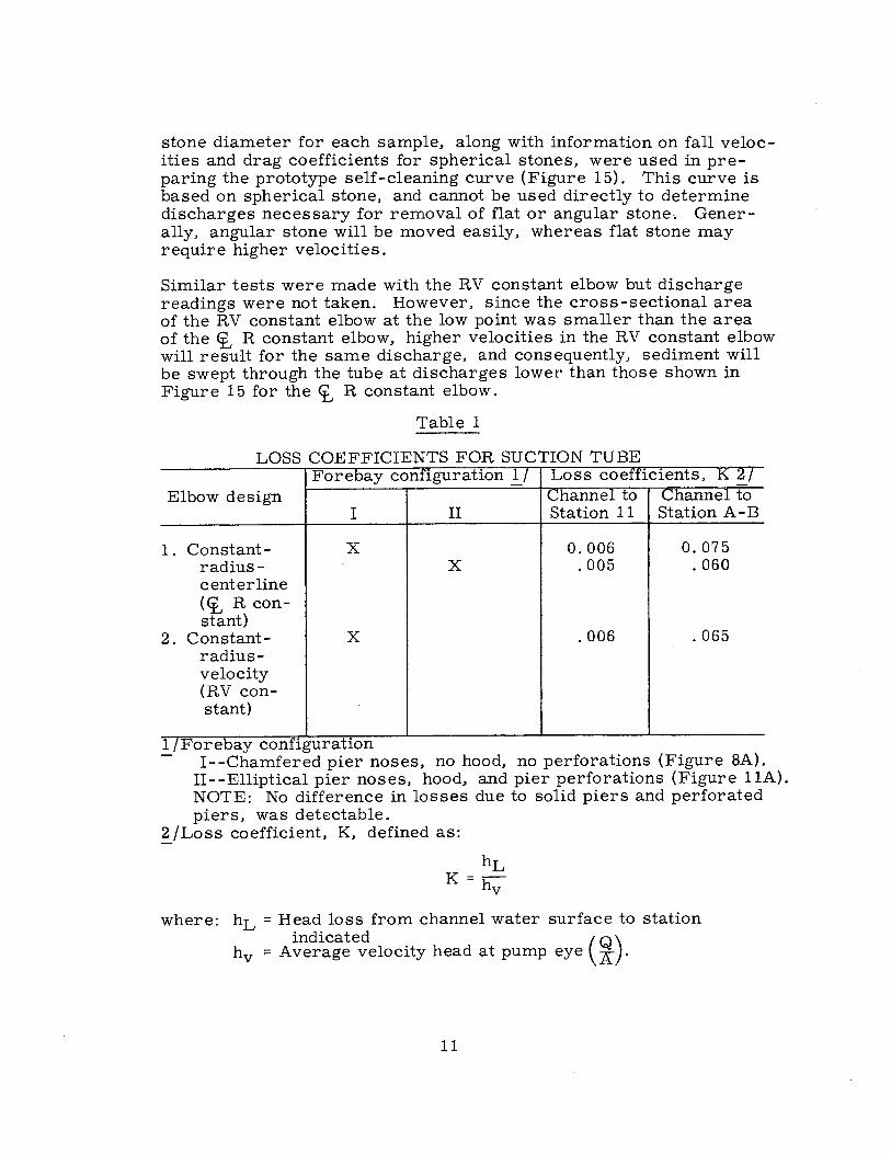
The loss coefficients for the suction tubes with the ct, R constant · and the RV constant elbows are contained in Table L These coef- -ficients, in terms of velocity head at the pump eye, give the total head loss from the channel to Station 11 just ahead of the elbows, and the complete tube loss to Station A-B. The loss coefficients for the complete suction tube with the 't, R constant elbow installed were 0. 075 without the hood, and 0. 060 with the hood, respectively. The coefficient for the tube with the RV constant elbow installed was 0. 065 without the hood in the forebay. The RV constant elbow was not tested with the hood. Sample data calculations based on readings obtained with the Van der Hegge sphere are contained in the Appendix.
The velocity- profiles at the outlet of the suction tube,. Station A-B, we·re quite fl.at and well developed with either of the elbows installed (Figures 12 and 13). Similarly, the losses were very nearly identical, and the overall performance of the suction tube with either elbow was nearly the same. Design and construction -costs, however, favored the use of the ct, R elbow, and its· basic form is used in the Forebay and Mile 18 plants.· ·
9
Elbows Calibrated as Flowmeters
Both elbows were calibrated as flowmeters. Several piezometer locations were analyzed to determine positions that would provide an appreciable differential that consistently increased with increasing discharge. The most satisfactory positions were located diametrically opposite one another on the crown and invert of the elbows 67. 5° around the bend (Figures 2 and 3).
The equation used for calculating the discharge coefficients for the elbows was:
where: Cd = Discharge coefficient Q = Discharge in cubic feet per second A = Area at the station 67. 5° along the bend Ah = Differential head between the piezometer readings
on the inside and outside of the bend.
The <:t, R constant elbow was calibrated at intervals of 64 cubic feet per second from 0 discharge up to 768 cubic feet per second. The differential pressures are presented in Figure 14B, and the discharge coefficient was found to be 0. 661 based on the suction tube area of 84. 278 square feet located 67. 5° around the bend.
The RV constant elbow was calibrated as a flowmeter at discharges from i92 to 768 cubic feet per second. The discharge coefficient was found to be 0. 611, based on the suction tube area of 77. 070 square feet at the station 67. 5° along the bend (Figures 3 and 14B).
Self-cleaning Characteristics
Tests were made to determine if the suction tube, with either elbow installed, would be self-cleaning of any sediment and sand or gravel that the water could carry in. The procedure used with the tube containing the <i, R constant elbow consisted of separating coarse sand and fine gravel by size into five groups. The dry stone weight of each group was determined by an analytical balance and the stone volume was obtained by water displacement. From the volume and weight. equivalent spherical diameters and density were obtained. The average density of the stone used was 163. 5 pound·s per cubic foot, and the stones were sub rounded. A number of stones of a particular size were then placed in the low point of the suction tube and the discharge gradually increased until the stones were swept out. The sweep-out discharge and the spherical
10
stone diameter for each sample, along with information on fall velocities and drag coefficients for spherical stones, were used in preparing the prototype self-cleaning curve (Figure 15). This curve is based on spherical stone, and cannot be used directly to determine discharges necessary for removal of flat or angular stone-. Generally, angular stone will be moved easily, whereas flat stone may require higher velocities.
Similar tests were made with the RV constant elbow but discharge readings were not taken. However, since the cross-sectional area of the RV constant elbow at the low point was smaller than the area of the ~ R constant elbow, higher velocities in the RV constant elbow will result for the same discharge, and consequently, sediment will be swept through the tube at discharges lower than those shown in Figure 15 for the <t, R constant elbow.
Table 1
LOSS COEFFICIENTS FOR SUCTION TUBE Forebay configuration 1 / Loss coenicients, K 2 /
Elbow design Channel to channel to I II Station 11 Station A-B
1. Constant- X 0.006 0.075 radius- X .005 . 060 centerline (~ R con-stant)
2. Constant- X .006 . 065 radius-velocity (RV con-stant)
1 /Foreba confi y g uration !--Chamfered pier noses, no hood, no perforations (Figure 8A).
II--Elliptical pier noses, hood, and pier perforations (Figure 11A). NOTE: No difference in losses due to solid piers and perforated piers, was detectable.
2 /Loss coefficient, K, defined as:
where: hL = Head loss from channel water surface to station indicated (Q)
hv = Average velocity head at pump eye A .
11
APPEINDIX
13
APPENDIX
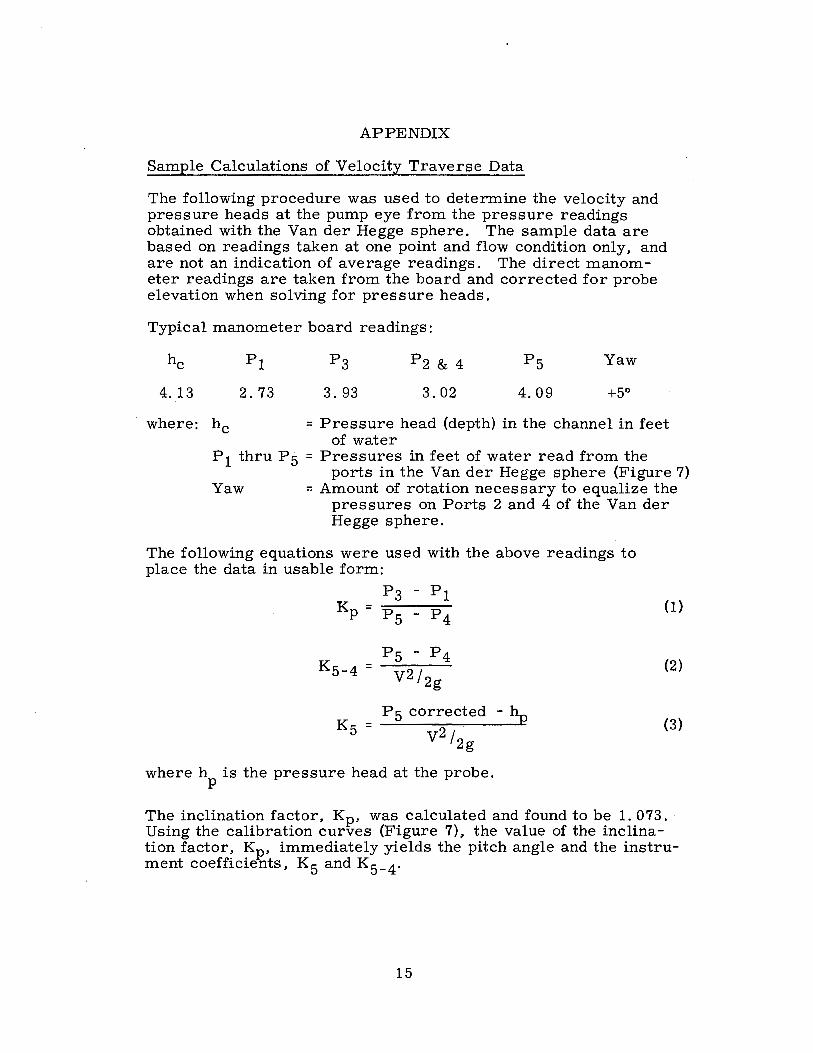
Sample Calculations of Velocity Traverse Data
The following procedure was used to determine the velocity and pressure heads at the pump eye from the pressure readings obtained with the Van der Hegge sphere. The sample data are based on readings taken at one point and flow condition only, and are not an indication of average readings. The direct manometer readings are taken from the board and corrected for probe elevation when solving for pressure heads.
Typical manometer board readings:
4.13
where: he
pl
2.73
P 1 thru P 5
Yaw
P2 & 4
3.02
Yaw
+50
= Pressure head (depth) in the channel in feet of water
= Pressures in feet of water read from the ports in the Van der Hegge sphere (Figure 7)
= Amount of rotation necessary to equalize the pressures on Ports 2 and 4 of the Van der Hegge sphere.
The following equations were used with the above readings to place the data in usable form:
P3 - P1 K = --- (1) . p P5 - P4
P5 - P4 K5-4 = --- (2)
V2/ 2g
P 5 corrected - hp K5 = _____ __._ (3) v2 l2g
where h is the pressure head at the probe. p
The inclination factor, Kp, was calculated and found to be 1. 073. Using the calibration curves (Figure 7), the value of the inclination factor, Kp, immediately yields the pitch angle and the instrument coefficients, K 5 and K 5 _4 .
15
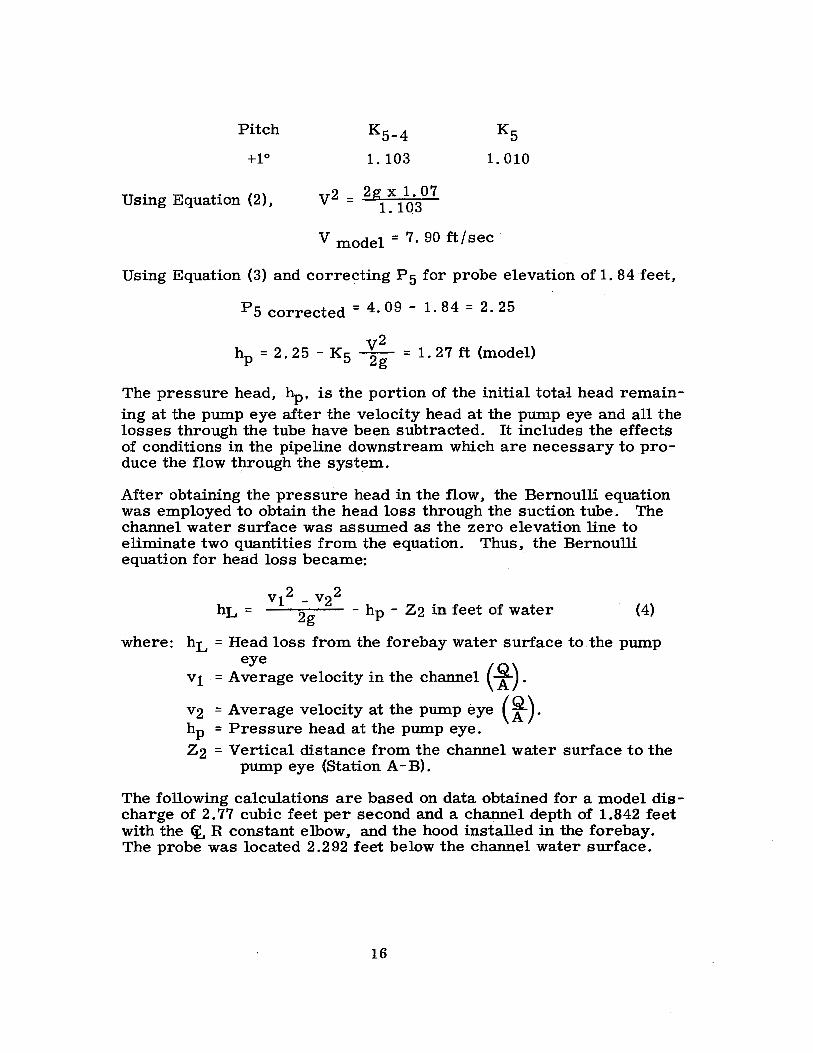
Pitch
+10
Using Equation (2),
K5-4
1.103
v2 = 2g X 1. 07 1. 103
V model= 7. 90 ft/sec·
Using Equation (3) and correcting P5 for probe elevation of 1. 84 feet,
P5 corrected = 4. 09 - 1. 84 = 2. 25
v2 hp = 2. 25 - K5 2g = 1. 27 ft (model)
The pressure head, hp, is the portion of the initial total head remaining at the pump eye after the velocity head at the pump eye and all the losses through the tube have been subtracted. It includes the effects of conditions in the pipeline downstream which are necessary to produce the flow through the system.
After obtaining the pressure head in the flow, the Bernoulli equation was employed to obtain the head loss through the suction tube. The channel water surface was assumed as the zero elevation line to eliminate two quantities from the equation. Thus, the Bernoulli equation for head loss became:
v12 - v22 hL = 2g - hp - Z2 in feet of water · (4)
where: hL = Head loss from the forebay water surface to the pump eye
v1 . = Average velocity in the channel ( f) . v2 = Average velocity at the pump eye ( i). hp = Pressure head at the pump eye. Z2 = Vertical distance from the channel water surface to the
pump eye (Station A - B).
The following calculations are based on data obtained for a model discharge of 2. 77 cubic feet per second and a channel depth of 1.842 feet with the (I. R constant elbow, and the hood installed in the forebay. The probe was located 2.292 feet below the channel water surface.
16
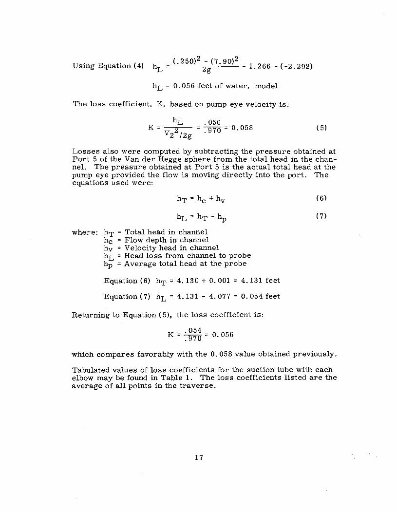
Using Equation(4) hL = <- 250>2 2-g( 7 . 90>2 - 1.266 -(-2.292)
hL = 0. 056 feet of water, model
The loss coefficient, K, based on pump eye velocity is:
hL . 056 K = 2 = 970 = 0. 058
V2 /2g . ( 5)
Losses also were computed by subtracting the pressure obtained at Port 5 of the Van der Hegge sphere from the total head in the channel. The pressure obtained at Port 5 is the actual total head at the pump eye provided the flow is moving directly into the port. The equations used were:
hT =he+ hv
hL = hT - hp
where: hT = Total head in channel he = Flow depth in channel hv = Velocity head in channel hL = Head loss from channel to probe hp = Average total head at the probe
Equation (6) hT = 4.130 + 0. 001 = 4.131 feet
Equation ( 7) hL = 4. 131 - 4. 077 = O. 054 feet
Returning to Equation ( 5)., the loss coefficient is:
K = : ~~~ = 0. 056
( 6)
( 7)
which compares favorably with the 0. 058 value obtained previously.
Tabulated values of loss coefficients for the suction tube with each elbow may be found in Table 1. The loss coefficients listed are the average of all points in the traverse.
17
10 12
KEY MAP
13 14
10
FIGURE I REPORT HYO. 5'13
15 16 17 18 19
10 20
SCALE OF MI LES
© ALWAYS nunK SAfETV UNITED STATES
DEPARTMENT OF THE INTERIOR BUREAU OF RECLAMATION
CENTRAL VALLEY PROJECT
R.20 E.
30
WEST SAN JOAQUIN DIV. -SAN LUIS UNIT-CALIFORNIA
MILE 18 AND FOREBAY PUMPING PLANTS.
LOCATION MAP
OtrNVER, COLORADO BlrPT. Zit, 1982
Max. w.s. EL.173.00 (4200 cfs)-, )
Min. W.S. EL.172.00 (3800 cfs)-, _: I
-_=-
~ End of center pier-------
1<- --5.04'- ->t<- -3.56'~ El.156.08-,, I I I '
r -- OT (' -;--!;I ,' ' ' : /Ei.152.52--,
! ',I. __ ' ' I I
' : I I
:
I
-"' ~ !!!. ,'
'
/
,
,--Headwall
x2 __ y_2 _ --. + (3. 856) 2 ,/ (19.754) , , ,/"' /
', I
-~·r, '•-f , .
, , -Axis,
\ -~SJ I I
' ' ' ' I I I _, g 'P I
' ' ' ' '
<-- < t:\,tt --- t---- -- ,~;;~;,"-- -- t , I
' ' ' ' : I
' ' : ' : ,--End of _ l/ center pier
-----~~r·1 II I I I I I I I '6 9
·o 9 ~ :
' : ' - ' g
c,; I ' I I
: ' '
a,
' ' ' ' ' ' I I I I
' : I
i i i i i i i i i i i i
~ .,; T
FIGURE 2 REPORT HYO. 513
__________ P~~::~c ___________________ ---+ _____ P~:~t~c ___ --~
"le ..,:
' : 'a,
"' .,;
-<-STATIONS-> Mox. w. s. EL.173.00 (4200 cfs)-.
M. / f ) \ ' In. W.S. EL.172.Q0 (3800 C S ---,,, = 22 21 20 19 18 17 16 15 14 13 12 II 9 8 7 6 5 4 2 A-8
El.156.08-\
.. ,
~~~
jF!C.
' / I
IEl.152.52--, I •
: - '·>· J V "' •/ ~ /~. ~ / r /
I / ' / ' / ' / I / I ,
I ' / II,/ II., I ~-------8.60 ------
,--Hood
A. INITIAL INLET DESIGN VERTICAL HEADWALL ' 250
200 )
, End of center pier .... UJ UJ IL
.............
------ ------36.17'
<i. Impeller__ ,- Primary velocity +i
',,, / traverse location co ' , 0
El.153.oo .. ,',, ,' .----+--,.-- -f
~ o_._=_6~1r2~'. ___ ~-T
Location of intermediate velocity traverses-\
' ' l .,,r::-------:.:.:.-:.t-
./.,. ·, '',ft.. ; -,/ I ~ /
/ \ ·/,,>,: _,/ I _,." ' , ' , ., L..t:,.------
' '
: I
' ' +I 0 "'
' a:i
I . -----D=8.28'------ -1--if________ j I I -r:,
I' r<> '' . ' I N I I N
' ' ' ' ' ' / : ,' ' , _, , "'
/ t--; / ~
/ ' , ' , I
/ ' 'fr-., ,/ :
/ ' ,,.,, :
UJ 150 a: <( ~ d
"' 0 <t 100
UJ a: <(
'
'
... ~ ,,,,,,, : t
', _, , ' ,El,130.67 9 7
---6 -----::::<~'- _____________ y ___ yp
~--- '·--T-Two piezometers located
Spaces@ 15°• 1°0
--------~ midway between Sta. 5ond 6 ---9
B. FINAL DESIGN WITH HOOD
DEVELOPED PLAN ALONG CENTER LINE
NOTE: Dotted line from Sta.18ta Sto.22 indicates Area-Velocity for inlet with vertical headwall.
' .......
-- ~
-
--22 21 20 19 18 17 16 15 I ~- -- -- - ----- - - - --- - - -- - TRANS IT ION---
NOTE: All dimensions ore prototype.
I 0
SCALE OF FEET
Velocity-- -~, ~ .£Area (0.=700 cfs) .,,,--- __, -- _; - ..... ~- -....-
~ -- -
/ / ,,
/ /
/ I/
-- --
25
20 O z 0 u UJ !/)
II
5 ::; 11.
.... UJ ... IL
0 I
>.... u g ...
5 >
0 14 13 12 II 10 9 8 7
-<-STATIONS->- ! ---------+ ----- ---- -6 5 4 3 2 I
I
ELBOW-- -- - - ---- - - - -------t----- -CONE
t ------~
10
AREA-VELOCITY CURVES
135 DEGREE PUMP SUCTION TUBE STUDIES i R CONSTANT SUCTION TUBE
STUDY DRAWING FOR MODEL USE
661
FIGURE 3 REPORT HYD. 513
~-------- _________ _,_ --- Pl • ";' El bow ---- ---- -- --------r' --Pl .. t ;, Cone ---7
I ~ I
i 10
STA. No.
I 2 3 4 5 6 7 8 9 10
-"' "' U)
-.,,
"'
! I 0 10
SCALE OF FEET
Traverses for contours token at station A-B---\ ~
I 9
15
~----Stations ---- ,
I A
l Impeller- ... ~ \ {: _
---6. I 25' ---- \_-i-A
8 7 6 5 4 3 2 /
' I I I
+I -0
DEVELOPED PLAN ALONG CENTER LINE /.I' /;{
"'
J ,.;
/ 111 / I I/
/ I l~"-To fit transition Sto.10, /. / 1 / \ ,~,..._ - _ ::···· __ ,_,,. __ ----l-
Q = 700 cfs. Figure 2.-----,,,_ / o , / I I'",--:;-
9 I \ ' k ._
o;~~··:/ / I / : I'{\'
---- I
........... , ... 8./7!. .. _ /
R ( FEET)
6.07 6.65 7 .27 7 .80 8.34 9.09 10.01 10.90 11.90 12.95
I-laJ laJ IL
laJ 0:: <t ::, 0
"' I
<t laJ 0:: <t
V (FT./SEC.l
13.03 11.88 10.85 10.11 9.46 8.69 7.87 7.24 6.63 6.10
250
200
150
100
50
0
RV AREA (SQ. /FT.)
79.0- 53.80 79.0 58.98 79.0 64.53 79.0 69.26 79.0 74.00 79.0 80.60 79.0 89.00 79.0 96.70 79.0 I 05.55 79.0 115.00
Area: y
', I
I
I I
Ci,• / f I / I I
-;,; -~ v l '>-~ =z----:t·
El.134.4~) I
I I ,·
I
,{ ',,,
' ............
,-- Velocity-, ,--
0 !!! ,,: I I
.,: ' :
,, , /
I I
, '-2 Piezometers for · ~ co Ii brotion purposes
···--9 Spaces @ 15• = 135•---/ 67f along bend.
SECTION
I
I
I
,_
25
20 C z 0 u Ill a,
15 0:: Ill CL
1-111 Ill IL
10 I ~
.!:: u g laJ
5 >
10 9 B 7 6 5 4 3 2 I --<- Stations A 0
I I I ~ -----------------ELBOW-------------------+------ CONE----- >-j
AREA -VELOCITY CURVES
135 DEGREE PUMP SUCTION TUBE STUDIES RV CONSTANT SUCTION ELBOW
STUDY DRAWING FOR MODEL USE
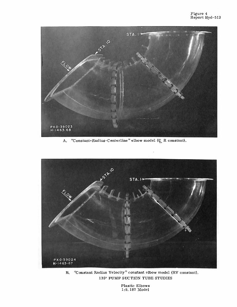
A. "Constant-Radius-Center line" elbow model (<t, R constant).
Figure 4 Report Hyd-513
B. "Constant Radius Velocity" constant elbow model (RV constant).
135° PUMP SUCTION TUBE STUDIES
Plastic Elbows 1 :9. 187 Model

~ .I"" ':' 'N
/ .... --For pier arrangement see ·-' Detail A
L I II'~ =--,
0 -------6 x 6 Pump
'-·---0" Vo!ve r!' Line····/ a" Valve_./
P L A N
NOTE, All dimensions ore for model.
............................. 20'---- .... _ ................................... 1 ['............. .... i ~ ... 2'· 6''. ... "i ' ~ · ,·Rock Baffle ,,--
.. 4" ~ -~
\'·Drain to Channel ·-a" Venturi Meter ···a" Line ! ::
-~
ELEVATION
~t -'? !
.,/· Sheet meta! transition
__ /
_x_2_+ y2 y (5.88")2 (1.143")2 = I·.... !"·5.88"-"!
C ·"@;J
* re
Axes..-,:;:,•·
PLAN
L-----12.so"-----J / • I Qc'
i ~ j? i/ i
ELEVATION
DETAIL B
E N D VIEW
=l'l")=f"'i=
~~U) cici c-..i
~ix Dummy pier~--...
;,; ;'
' ·c_-~F",~ Symmetrical I ,Center ' !
about ct, • .., A~~:,.L,!\er~ ! .--:'- ·', .
i i =\ \•r---=,..:.. O.llt1rj- 1
i A ~ }1:'.:~ f. LD9(-=,"°L ·o ' ·.-;, :~ , __
. 1~ i ____ _ Dummy pier ___ /
\For elliptical pier nose See Detoi! B
P L AN
DETAIL A
---t-""I
! !
-,~ jA I tr: ... ,.
' " --'0.65 R fil!et
?-87,r·;:~:.~6 -~~ ·~~:~:::::~
r··.::: .. J ~ i '\ ii I ·, ! =!2 I
"' m
"' re
\..--·-Sta. 18
I
SECTION A-A
135 DEGREE PUMP SUCTION TUBE STUDIES MODEL DETAILS
1,9.187 SCALE
GPO 83S.762
::: .. ..,, o-
~~ "'::O ~ITI
"'"' "
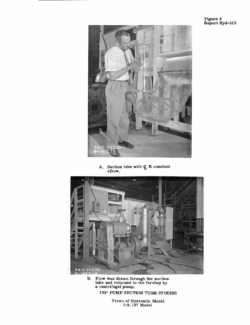
A. Suction tube with <t, R constant elbow.
Flow was drawn through the suction tube and returned to the forebay by a centrifugal pump.
135° PUMP SUCTION TUBE STUDIES
Views of Hydraulic Model 1:9. 187 Model
Figure 6 Report Hyd-513
661
1.1
1.0
0.9
0.8
0.7
0.6
st I
,n lo: 0.5 a: 0 ,n 0.4
lo:
en I- 0.3 z I.LI
o 0.2 LL LL I.LI
g 0.1
1-z I.LI 0.0 :E ::::, a: I- -0 .I en z
-0.2
-0.3
-0.4
-0.5
-0.6
-0.7
__ 1--. i(_ -Ks-4
·- - - -_lb --Ks ~ ... ..f~ ~ ·- -~
I I I v;
I I I I
j ' I I
A, I'<--I
~
!~ \ I
\ I
4 I \ I I I j I I
I/ I I I I
!/
K5_4
'\
~ /' \
\ \
/
\
\ '
-Ks I\
FIGURE 7 REPORT HYO. 513
2.5
2.0
1.5
I Y--- --E-- r----f\--- --<.--- ~--- 11.
I Kp-- -!1 \ I I t ' I \
I J I \ I
t
I I I
i'v'--50 -40 -30 -2d -10 0 10 20 30 40
J Pl TCH ANGLE I I I I I
I I
$ J h" -I I
I
AXIS OF ROTATION / 0.500" DIAMETER FOR YAW ANGLE-( SPHERE
J ' I 0.250" DIAMETER )
ff) STEM----Jl; / -
I // . s ' ' / + I - ' '
I /''-. I ,,-I',
P3 - P1 ----±-/ Kp = Ps - P4 ~-->
Pl TCH ANGLE
I K = P5 - P4
t s-4 wz/ 2 g
I K _ P5 CORRECTED - hp 5 - V2/2g
135 DEGREE PUMP SUCTION TUBE STUDIES CALIBRATION CURVE FOR VAN DER HEGGE SPHERE
50
-----
1.0 lo:
0.5
0.0
0.5
-1.0
-1.5
a: 0 lo <t LL
z 0
I-<t z ..J u z
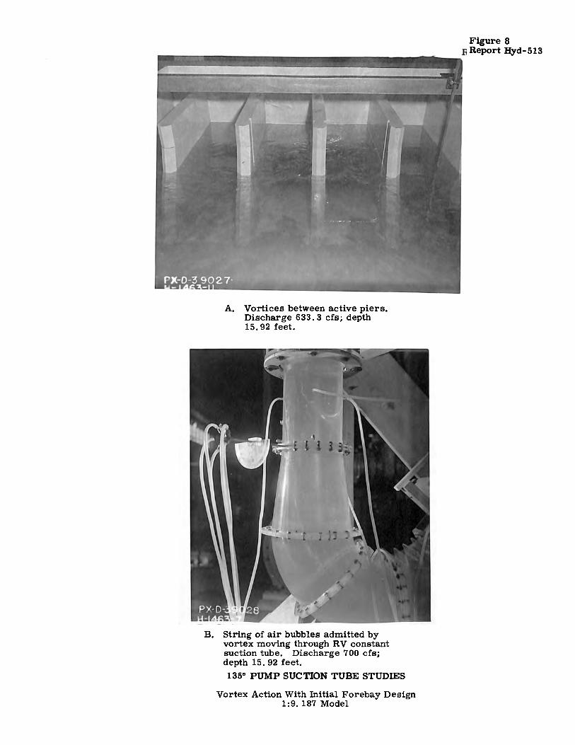
A. Vortices between active piers. Discharge 633. 3 cfs; depth 15. 92 feet.
B. String of air bubbles admitted by vortex moving through RV constant suction tube. Discharge 700 cfs; depth 15. 92 feet. 135° PUMP SUCTION TUBE STUDIES
Vortex Action With Initial Forebay Design 1:9. 187 Model
Figure 8 Report Hyd-513
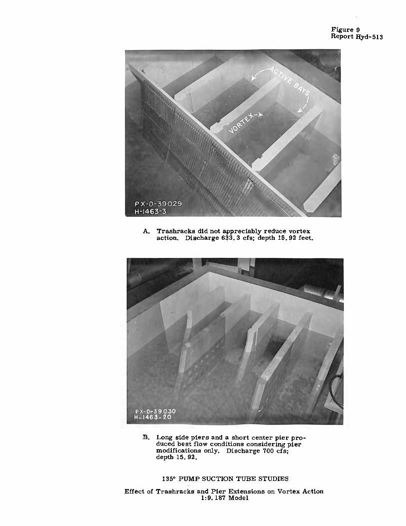
A. Trashracks did not appreciably reduce vortex action. Discharge 6~3. 3 cfs; depth 15. 92 feet.
B. Long side piers and a short center pier produced best flow conditions considering pier modifications only. Discharge 700 cfs; depth 15. 92.
135° PUMP SUCTION TUBE STUDIES
Effect of Trashracks and Pier Extensions on Vortex Action 1:9. 187 Model
Figure 9 Report Hyd-513
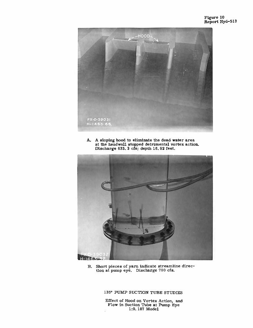
A. A sloping hood to eliminate the dead water area at the headwall stopped detrimental vortex action. Discharge 633, 3 cfs; depth 16. 92 feet.
B. Short pieces of yarn indicate streamline direction at pump eye. Discharge 700 cfs.
135° PUMP SUCTION TUBE STUDIES
Effect of Hood on Vortex Action, and Flow in Suction Tube at Pump Eye
1:9. 187 Model
Figure 10 Report Hyd-513
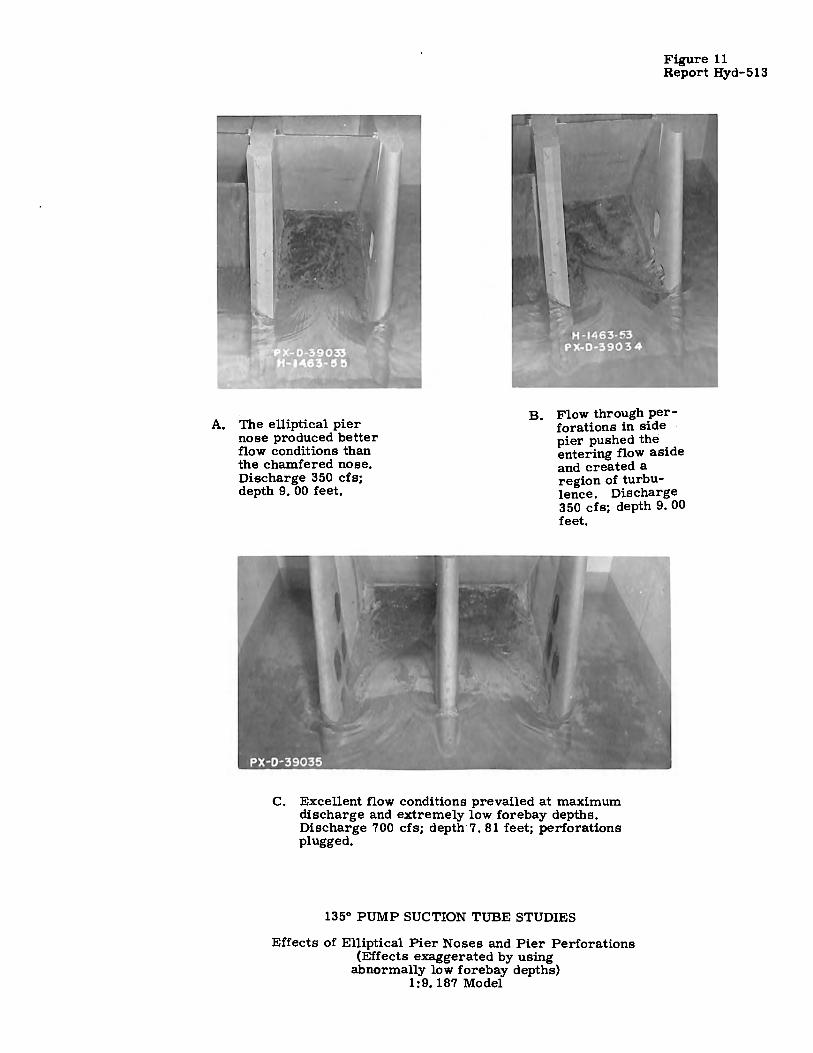
A. The elliptical pier nose produced better fl.ow conditions than the chamfered nose. Discharge 350 cfs; depth 9. 00 feet.
Figure 11 Report Hyd-513
B. Flow through perforations in side · pier pushed the . entering fl.ow aside and created a region of turbulence. Discharge 350 cfs; depth 9. 00 feet.
C. Excellent flow conditions prevailed at maximum discharge and extremely low forebay depths. Discharge 700 cfs; depth 7. 81 feet; perforations plugged.
135° PUMP SUCTION TUBE STUDIES
Effects of Elliptical Pier Noses and Pier Perforations (Effects exaggerated by using
abnormally low forebay depths) 1:9. 187 Model
661
.---------Inside of Bend
·----------Outside of Bend
----------Outside of Bend
FIGURE 12 REPORT HYO. 513
FLOW CONDITIONS (MODEL) Discharge = 2 .74 C.F.S.
Channel Depth = 1.842 FT.
Average Velocity = 7. 85 F. P. s.
FLOW CONDITIONS (PROTOTYPE)
Discharge = 700 c. F. s.
Channel Depth = 16.92 FT.
Average Velocity= 23.7 F.P.S.
FLOW CONDITIONS (MODEL)
Discharge = 2 .48 c. F. s.
Channel Depth = I. 732 FT.
Average Velocity = 7. I F. P.S.
FLOW CONDITIONS (PROTOTYPE)
Discharge = 633.3 C.F.S.
Channel Depth= 15.92 FI
Average Velocity = 21.5 F. P.S.
Data Plotted as t'lG.
135 DEGREE PUMP SUCTION TUBE STUDIES VELOCITY CONTOURS AT STATION A-B FOR
THE i.R CONSTANT SUCTION TUBE
DATA FROM I: 9.187 MODEL

FIGURE 13 REPORT HYO. !113:
661
----------Inside of Bend
'--------,Outside of Bend
,---------Inside of Bend
---------Outside of Bend
FLOW CONDITIONS (MODEL) Discharge = 2.74 C.F.S.
Channel Depth = 1.842 FT.
Average Velocity = 7. 85 F. P.S.
FLOW CONDITIONS (PROTOTYPE) Discharge= 700 C.F.S.
Channel Depth= 16.92 FT.
Average Velocity= 23.7 F. P.S.
FLOW CONDITIONS (MODEL)
Discharge = 2 .48 C. F. S.
Channel Depth= 1. 732 FT.
Average Velocity = 7.1 F. P.S.
FLOW CONDITIONS (PROTOTYPE) Discharge = 633.3 C.F.S.
Channel Depth = 15.92 FT.
Average Velocity= 21.5 F. P.S.
Doto Plotted as _vv AVG.
135 DEGREE PUMP SUCTION TUBE STUDIES VELOCITY CONTOURS AT STATION A-B. FOR
THE RV CONST ANT SUCTION TUBE
DATA FROM I: 9.187 MODEL
661
0 .I .2 .3
FIGURE 14 REPORT HYO. 513
4 V/vAVG. BETWEEN STA. 6 AND 7
:o V/vAVG. BETWEEN STA. I AND 2
FLOW CONDITIONS
DISCHARGE (C.F.$.)
MODEL
2.48
1.842
PROTOTYPE .
633.3
16.92
.4 .5 .6 . ._7
d;D .8 .9 1.0
d.,. Distance fram inside of bend.
D- Traverse length
A. VELOCITY TRAVERSES AT INTERMEDIATE STATIONS IN THE i R CONSTANT SUCTION TUBE
o I. R CONSTANT SUCTION tUBE
A RV CONSTANT SUCTION TUBE
51-----------------..__ ___ ..__ ___ ..__ ___ ..__ __ ---I
Differential readings, Ah, obtained from piezometers located on the crown and invert of the elbows, 67.5 degrees around the bend,
~4~---------------~---~---~---~-~~ I<(
3: 0 A
AREA A 84.278 H 2 77.070 FT 2
IL COEF. Cd 0.661 0.611 031-----~-------~---~---~---~-~-~-~,-f 1-w w IL
~2~---~---~--~~---~---~~~-~~~-~-----1 <I
100 200 300 400 500 600 PROTOTYPE DISCHARGE {C.F.S.)
8. DIFFERENTIAL VS. DISCHARGE CURVE
135 DEGREE. PUMP SUCTION TUBE STUDIES INTERMEDIATE VELOCITY . TRAVERSES AND
DIFFERENTIAL vs DISCHARGE CURVES
DATA FROM 1: 9.187 MODEL
700 800
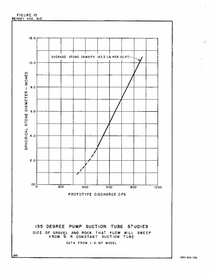
FIGURE 15 REPORT HYO. 513
en LLI ::c 0 z
a:: IJ.J .,_ IJ.J :!!: <t C
IJ.J z 0 .,_ CJ)
_J
<t 0 a:: w ::c a.. CJ)
661
12.0
10.0
AVERAGE STONE DENSITY 163.5 LB. PER CU. FT.-- --y
I 8.0
I I
6.0 I
I 4.0 I
I , I
I 2.0
~ , I
/ / ,,
000 200 400 600 800
PROTOTYPE DISCHARGE CFS
135 DEGREE PUMP SUCTION TUBE STUDIES
SIZE OF GRAVEL AND ROCK THAT FLOW WILL SWEEP FROM <t. R CONSTANT SUCTION TUBE
DAT A FROM I: 9.187 MODEL
1000
GPO 835•762