hydraulic pump division xl series p1/pd models hydraulics/01 - axial... · d1 case drain port f e2...
TRANSCRIPT

Hydraulic Pump Division XL Series
P1/PD Models open-circuit axial piston pumps
280 bar rated pressure
Publication LTE-00049-1
Revision E 30 March 2005

DESCRIPTION
2
description • variable displacement, axial piston pump for open-circuit applications • medium pressure, continuous operation at pressures up to 280 bar • high drive speed models for mobile markets • low noise models for industrial markets • quiet and efficient control capability benefits • compact overall package size • quiet operation • low flow ripple to further reduce noise • elastomer seals that eliminate gaskets and external leakage • high operating efficiency for lower power consumption and reduced heat generation • simple hydraulic controls with “no-leak” adjustments • meets global standards for ISO and SAE mounting flanges and ports • long life, tapered-roller shaft bearings • long life, low friction, hydrostatically balanced cam bearings • full power through-drive capability • end or side inlet and outlet ports • case drain ports for horizontal or vertical, shaft-up mounting • optional minimum and maximum displacement adjustments • optional case-to-inlet check valve to extend shaft seal life • easy to service

RATINGS AND INFORMATION
3
XL Series pump model 060 075 100 140
displacement maximum cm3/r 60 75 100 140 continuous bar 280
* intermittent bar 320 outlet pressure peak bar 350
maximum – boosted inlet rpm 2800 2700 2500 2400
maximum – 1.0 bar abs inlet rpm 2400 2300 2100 2000
maximum – 0.8 bar abs inlet rpm 2000 1900 1700 1600
speed (mobile version)
minimum rpm 600 maximum –
1.0 bar abs inlet rpm 1800
maximum- 0.8 bar abs inlet rpm 1800 1800 1800 1500
speed (industrial version)
minimum rpm 600 maximum bar 10
rated bar 1.0 absolute (0.0 gage) Inlet pressure
minimum bar 0.8 absolute (-0.2 gage)
peak bar 4.0 absolute (3.0 gage) and less than 0.5 bar above inlet pressure
case pressure rated bar 2.0 absolute (1.0 gage)
and less than 0.5 bar above inlet pressure
fluid temperature range °C -40 to +95 rated cSt 6 to 160
maximum intermittent cSt 5000 (for cold starting) fluid viscosity
minimum intermittent cSt 5
rated ISO 20/18/14 fluid contamination
maximum ISO 21/19/16 flange SAE 127-4 (C) 152-4 (D)
key shaft SAE 32-1 (C) 38-1 (C-C) 44-1 (D) SAE mounting spline shaft SAE 14T–12/24P 17T-12/24P 13T-8/16P
flange ISO 125B4 180B4 key shaft ISO E32N E40N E50N ISO mounting
spline shaft ISO 14T mod 2 18T mod 2 24T mod 2 end port kg 30 53 66 side port kg 31 55 67 weight
thru-drive kg 35 82
* Intermittent pressure is defined as less than 10% of operation time, not exceeding 10 successive seconds.

INSTALLATION DRAWINGS
4
ß2 places
P
A inlet portQ
R S B outlet port
ØB
Y - 4 places
D3 case drain port
ØA
W 4 places
D2 case drain port
V plug
N
KJ
M
L max
Z
pressure limiter adjustment screwload sensing adjustment screw
X load sensing portcontrol location for CCW rotation
control location for CW rotation
Gto port X
BG – outlet gage port
D1 case drain portF
E2C
end ports
E3
D3 case drain port
H

INSTALLATION DRAWINGS
5
B - outlet port
SCSE
SF
SG
SJ
SH
side ports(dimensions are the same as the end ported
pump except as shown)
A - inlet port
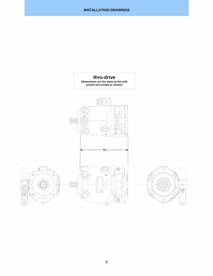
INSTALLATION DRAWINGS
6
thru-drive(dimensions are the same as the side
ported unit except as shown)
TC
DIMENSIONS
7
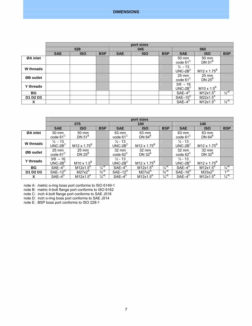
port sizes 028 045 060 SAE ISO BSP SAE ISO BSP SAE ISO BSP
ØA inlet 50 mm code 61C
50 mm DN 51B
W threads ½ - 13 UNC-2BC
M12 x 1.75B
ØB outlet 25 mm code 61C
25 mm DN 25B
Y threads 3/8 – 16 UNC-2BC
M10 x 1.5B
BG SAE–4D M12x1.5A ¼”E D1 D2 D3 SAE–10D M22x1.5A
X SAE–4D M12x1.5A ¼”E
port sizes 075 100 140 SAE ISO BSP SAE ISO BSP SAE ISO BSP
ØA inlet 50 mm code 61C
50 mm DN 51B
63 mm code 61C
63 mm DN 64B
63 mm code 61C
63 mm DN 64B
W threads ½ - 13 UNC-2BC
M12 x 1.75B
½ - 13 UNC-2BC
M12 x 1.75B
½ - 13 UNC-2BC
M12 x 1.75B
ØB outlet 25 mm code 61C
25 mm DN 25B
32 mm code 62C
32 mm DN 32B
32 mm code 62C
32 mm DN 32B
Y threads 3/8 – 16 UNC-2BC
M10 x 1.5B
½ - 13 UNC-2BC
M12 x 1.75B
½ - 13 UNC-2BC
M12 x 1.75B
BG SAE–4D M12x1.5A ¼”E SAE–4D M12x1.5A ¼”E SAE–4D M12x1.5A ¼”E D1 D2 D3 SAE–12D M27x2A ¾”E SAE–12D M27x2A ¾”E SAE–16D M33x2A 1”E
X SAE–4D M12x1.5A ¼”E SAE–4D M12x1.5A ¼”E SAE–4D M12x1.5A ¼”E note A: metric o-ring boss port conforms to ISO 6149-1 note B: metric 4-bolt flange port conforms to ISO 6162 note C: inch 4-bolt flange port conforms to SAE J518 note D: inch o-ring boss port conforms to SAE J514 note E: BSP boss port conforms to ISO 228-1
DIMENSIONS
8
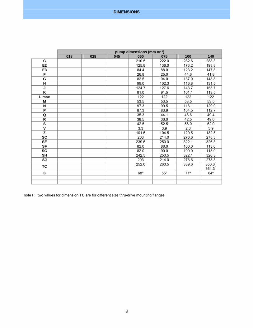
note F: two values for dimension TC are for different size thru-drive mounting flanges
pump dimensions (mm or º) 018 028 045 060 075 100 140
C 210.5 222.0 282.6 288.3 E2 125.8 136.0 173.2 193.8 E3 84.4 88.0 123.2 147.8 F 26.8 25.0 44.6 41.8 G 82.5 94.0 137.9 148.8 H 99.0 102.3 116.8 131.5 J 124.7 127.6 143.7 155.7 K 81.0 91.5 101.1 113.5
L max 122 122 122 122 M 53.5 53.5 53.5 53.5 N 97.3 99.5 116.1 129.0 P 87.3 83.9 104.5 112.7 Q 35.3 44.1 46.6 49.4 R 38.5 36.0 42.5 49.0 S 42.5 52.5 56.0 62.0 V 3.3 3.9 2.3 3.9 Z 101.5 104.5 120.5 132.5
SC 203 214.0 276.6 278.3 SE 239.5 250.0 322.1 326.3 SF 82.0 88.0 100.0 113.0 SG 82.0 90.0 100.0 113.0 SH 242.5 253.5 322.1 326.3 SJ 203 214.0 276.6 278.3
TC 252.0 263.5 339.6 350.3F 364.3F
ß 68º 55º 71º 64º

THRU-DRIVE SHAFT TORQUE CAPACITY
9
shaft torque capacity (N • m) shaft location shaft size & type 060 075 100 140
SAE C 32-1 key 562 562 SAE C-C 38-1 key 980 SAE D 44-1 key 1708 SAE C 14T spline 732 915 SAE C-C 17T spline 1220 SAE D 13T spline 1708 ISO E32N key 576 576 ISO E40N key 1157 ISO E50N key 1708 ISO 14T spline 732 915 ISO 18T spline 1220
input end
ISO 24T spline 1708 thru-drive end spline coupling 366 458 610 854

XL-75 PERFORMANCE DATA
10
XL-7550 C inlet oil temperature - ISO VG32 fluid - maximum displacement
60
70
80
90
100
110
120
130
140
150
160
170
180
0 50 100 150 200 250 300 350
pump outlet pressure (bar)
pum
p ou
tlet f
low
(lp
m)
.
1800 rpm
1200 rpm
1500 rpm
2300 rpm
XL-75 shaft input power at maximum displacement
50 C inlet oil temperature - ISO VG 32 fluid
0
10
20
30
40
50
60
70
80
90
0 50 100 150 200 250 300 350
pump outlet pressure (bar)
shaf
t inp
ut p
ower
(kW
)
2300 rpm
1800 rpm
1500 rpm
1200 rpm

XL-75 PERFORMANCE DATA
11
XL-7550 C inlet oil temperature - ISO VG 32 fluid - maximum displacement
55
60
65
70
75
80
85
90
95
0 50 100 150 200 250 300 350
pump outlet pressure (bar)
over
all e
ffici
ency
(%
) .
1800 rpm
1200 rpm
1500 rpm
2300 rpm
XL-75 shaft input power at zero outlet flow
50 C inlet oil temperature - ISO VG 32 fluid
0
2
4
6
8
10
12
14
0 50 100 150 200 250 300 350
pump outlet pressure (bar)
shaf
t inp
ut p
ower
(kW
)
2300 rpm
1800 rpm
1500 rpm
1200 rpm

XL-75 SOUND LEVEL
12
XL-75 Industrial Pump Typical Sound Levelmaximum displacement - anechoic conditions
ISO VG 32 fluid - 50 C inlet oil temperature
60
65
70
75
80
85
0 50 100 150 200 250 300 350
pump outlet pressure (bar)
soun
d pr
essu
re le
vel
dB(A
)
1800 rpm
1500 rpm
1200 rpm
XL-75 Industrial Pump Typical Sound Levelzero outlet flow - anechoic conditions
ISO VG 32 fluid - 50 C inlet oil temperature
60
65
70
75
80
85
0 50 100 150 200 250 300 350
pump outlet pressure (bar)
soun
d pr
essu
re le
vel
dB(A
)
1800 rpm
1500 rpm
1200 rpm

XL-75 SOUND LEVEL
13
XL-75 Mobile Pump Typical Sound Levelmaximum displacement - anechoic conditions
ISO VG 32 fluid - 50 C inlet oil temperature
65
70
75
80
85
90
0 50 100 150 200 250 300 350
pump outlet pressure (bar)
soun
d pr
essu
re le
vel d
B(A
)
2300 rpm
1800 rpm
1500 rpm
1200 rpm
XL-75 Mobile Pump Typical Sound Levelzero outlet flow - anechoic conditions
ISO VG 32 fluid - 50 C inlet oil temperature
65
70
75
80
85
90
0 50 100 150 200 250 300 350
pump outlet pressure (bar)
soun
d pr
essu
re le
vel d
B(A)
2300 rpm
1800 rpm
1500 rpm
1200 rpm
XL-75 BEARING LIFE
14
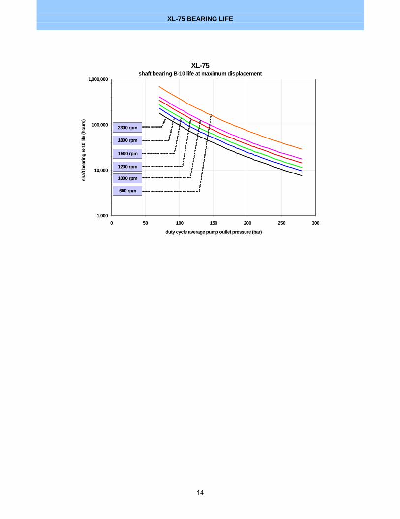
XL-75 shaft bearing B-10 life at maximum displacement
1,000
10,000
100,000
1,000,000
0 50 100 150 200 250 300
duty cycle average pump outlet pressure (bar)
shaf
t bea
ring
B-1
0 lif
e (h
ours
)
1800 rpm
2300 rpm
1500 rpm
1200 rpm
1000 rpm
600 rpm
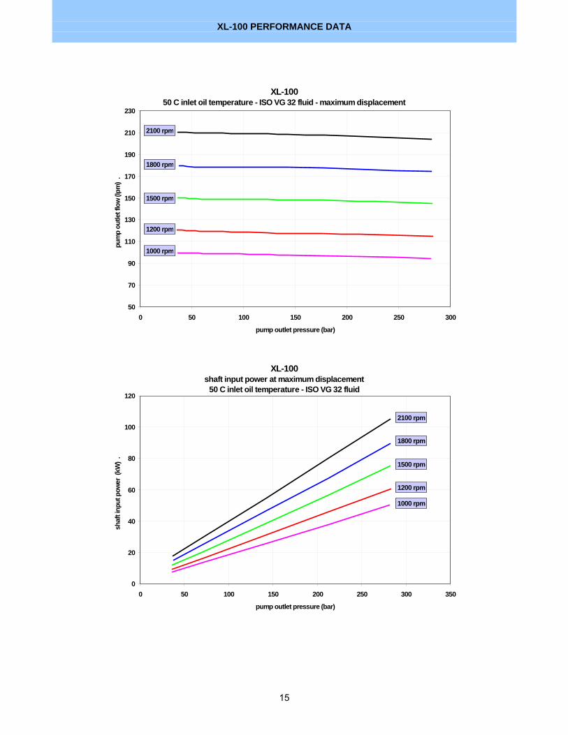
XL-100 PERFORMANCE DATA
15
XL-100 50 C inlet oil temperature - ISO VG 32 fluid - maximum displacement
50
70
90
110
130
150
170
190
210
230
0 50 100 150 200 250 300
pump outlet pressure (bar)
pum
p ou
tlet f
low
(lpm
) .
1800 rpm
1500 rpm
1200 rpm
1000 rpm
2100 rpm
XL-100shaft input power at maximum displacement
50 C inlet oil temperature - ISO VG 32 fluid
0
20
40
60
80
100
120
0 50 100 150 200 250 300 350
pump outlet pressure (bar)
shaf
t inp
ut p
ower
(kW
) .
1800 rpm
1500 rpm
1200 rpm
1000 rpm
2100 rpm

XL-100 PERFORMANCE DATA
16
XL-100 50 C inlet oil temperature - ISO VG 32 fluid - maximum displacement
70
75
80
85
90
95
0 50 100 150 200 250 300
pump outlet pressure (bar)
over
all e
ffici
ency
(%)
.
1800 rpm
1500 rpm
1200 rpm
2100 rpm
XL-100 shaft input power at zero outlet flow
50 C inlet oil temperature - ISO VG 32 fluid
0
2
4
6
8
10
12
14
16
0 50 100 150 200 250 300 350
pump outlet pressure (bar)
shaf
t inp
ut p
ower
(kW
) .
2100 rpm
1800 rpm
1500 rpm
1200 rpm

XL-100 SOUND LEVEL
17
XL-100 Industrial Pump Typical Sound Levelmaximum displacement - anechoic conditions
ISO VG 32 fluid - 50 C inlet oil temperature
60
65
70
75
80
85
0 50 100 150 200 250 300 350
pump outlet pressure (bar)
soun
d pr
essu
re le
vel d
B(A)
.
1800 rpm
1500 rpm
1200 rpm
XL-100 Industrial Pump Typical Sound Levelzero outlet flow - anechoic conditions
ISO VG 32 fluid - 50 C inlet oil temperature
60
65
70
75
80
85
0 50 100 150 200 250 300 350
pump output pressure (bar)
soun
d pr
essu
re le
vel d
B(A)
. 1800 rpm
1500 rpm
1200 rpm
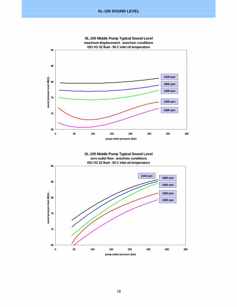
XL-100 SOUND LEVEL
18
XL-100 Mobile Pump Typical Sound Levelmaximum displacement - anechoic conditions
ISO VG 32 fluid - 50 C inlet oil temperature
65
70
75
80
85
90
0 50 100 150 200 250 300 350
pump outlet pressure (bar)
soun
d pr
essu
re le
vel d
B(A)
.
1800 rpm
1500 rpm
1200 rpm
1000 rpm
2100 rpm
XL-100 Mobile Pump Typical Sound Levelzero outlet flow - anechoic conditions
ISO VG 32 fluid - 50 C inlet oil temperature
65
70
75
80
85
90
0 50 100 150 200 250 300 350
pump outlet pressure (bar)
soun
d pr
essu
re le
vel d
B(A)
.
1800 rpm
1500 rpm
1200 rpm
1000 rpm
2100 rpm

XL-100 BEARING LIFE
19
XL-100shaft bearing B-10 life at maximum displacement
1,000
10,000
100,000
1,000,000
0 50 100 150 200 250 300
duty cycle average pump outlet pressure (bar)
shaf
t bea
ring
B-10
life
(hou
rs)
.
1200 rpm
1500 rpm
1800 rpm
2100 rpm
1000 rpm
600 rpm

XL-140 PERFORMANCE DATA
20
XL-140 50 C inlet oil temperature - ISO VG 32 fluid - maximum displacement
100
120
140
160
180
200
220
240
260
280
300
0 50 100 150 200 250 300
pump outlet pressure (bar)
pum
p ou
tlet f
low
(lpm
)
1800 rpm
1500 rpm
1200 rpm
1000 rpm
2000 rpm
XL-140 shaft input power at maximum displacement
50 C inlet oil temperature - ISO VG 32 fluid
0
20
40
60
80
100
120
140
160
0 50 100 150 200 250 300 350
pump outlet pressure (bar)
shaf
t inp
ut p
ower
(kW
)
2000 rpm
1800 rpm
1500 rpm
1200 rpm
1000 rpm
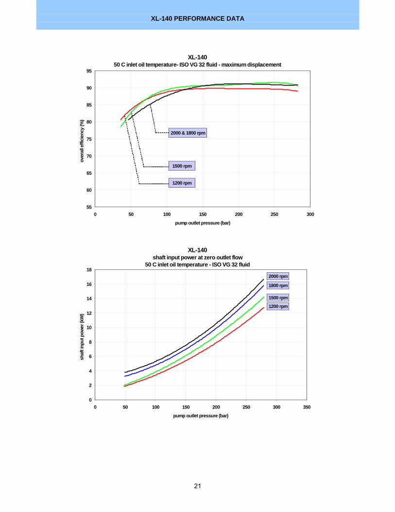
XL-140 PERFORMANCE DATA
21
XL-140 50 C inlet oil temperature- ISO VG 32 fluid - maximum displacement
55
60
65
70
75
80
85
90
95
0 50 100 150 200 250 300
pump outlet pressure (bar)
over
all e
ffici
ency
(%)
1200 rpm
1500 rpm
2000 & 1800 rpm
XL-140 shaft input power at zero outlet flow
50 C inlet oil temperature - ISO VG 32 fluid
0
2
4
6
8
10
12
14
16
18
0 50 100 150 200 250 300 350
pump outlet pressure (bar)
shaf
t inp
ut p
ower
(kW
)
2000 rpm
1800 rpm
1500 rpm
1200 rpm
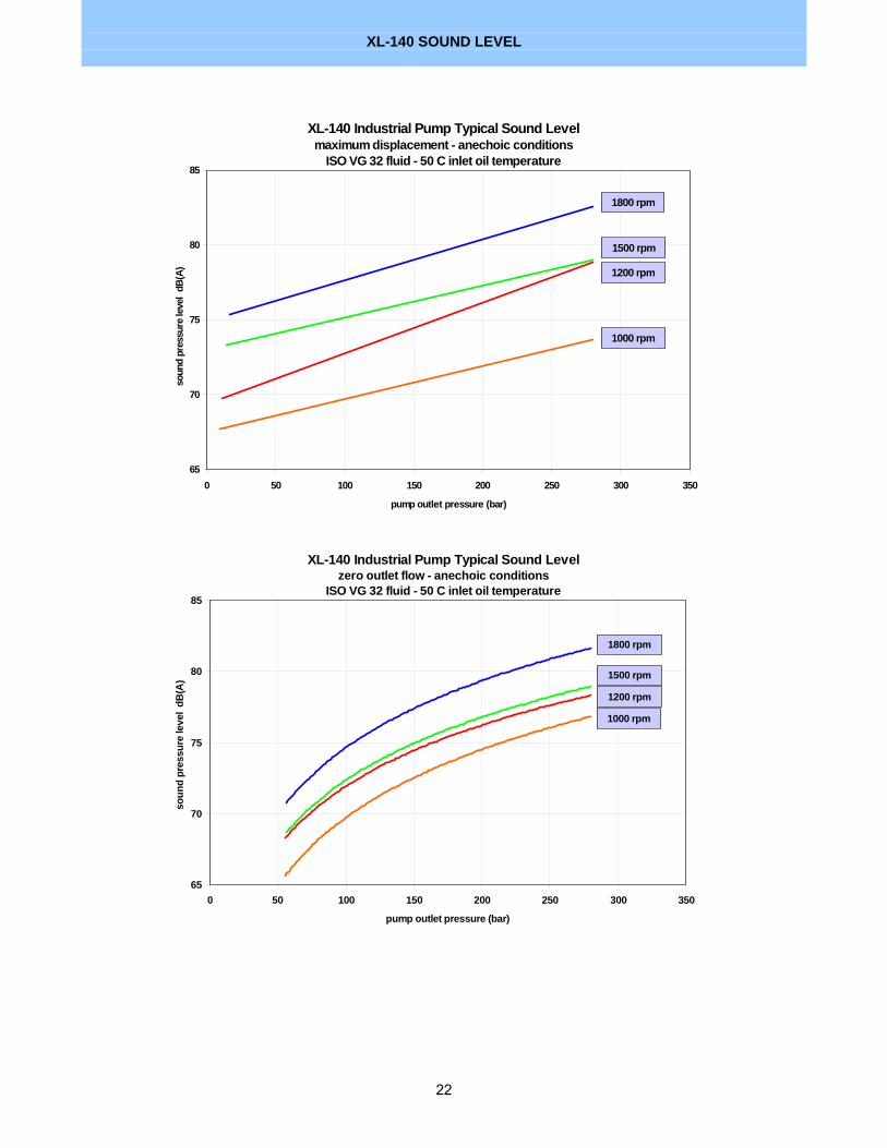
XL-140 SOUND LEVEL
22
XL-140 Industrial Pump Typical Sound Levelmaximum displacement - anechoic conditions
ISO VG 32 fluid - 50 C inlet oil temperature
65
70
75
80
85
0 50 100 150 200 250 300 350
pump outlet pressure (bar)
soun
d pr
essu
re le
vel
dB(A
)
1800 rpm
1500 rpm
1200 rpm
1000 rpm
XL-140 Industrial Pump Typical Sound Levelzero outlet flow - anechoic conditions
ISO VG 32 fluid - 50 C inlet oil temperature
65
70
75
80
85
0 50 100 150 200 250 300 350
pump outlet pressure (bar)
soun
d pr
essu
re le
vel
dB(A
)
1800 rpm
1500 rpm
1200 rpm
1000 rpm

XL-140 SOUND LEVEL
23
XL-140 Mobile Pump Typical Sound Levelmaximum displacement - anechoic conditions
ISO VG 32 fluid - 50 C inlet oil temperature
65
70
75
80
85
90
0 50 100 150 200 250 300 350
pump outlet pressure (bar)
soun
d pr
essu
re le
vel d
B(A)
1800 rpm
1500 rpm
1200 rpm
1000 rpm
2000 rpm
XL-140 Mobile Pump Typical Sound Levelzero outlet flow - anechoic conditions
ISO VG 32 fluid - 50 C inlet oil temperature
65
70
75
80
85
90
0 50 100 150 200 250 300 350
pump outlet pressure (bar)
soun
d pr
essu
re le
vel
dB(A
)
1800 rpm
1500 rpm
1200 rpm
1000 rpm
2000 rpm

XL-140 BEARING LIFE
24
XL-140 shaft bearing B-10 life at maximum displacement
1,000
10,000
100,000
1,000,000
0 50 100 150 200 250 300
duty cycle average pump outlet pressure (bar)
shaf
t bea
ring
B-10
life
(hou
rs)
1800 rpm
2000 rpm
1500 rpm
1200 rpm
1000 rpm
600 rpm
CONTROLS
25
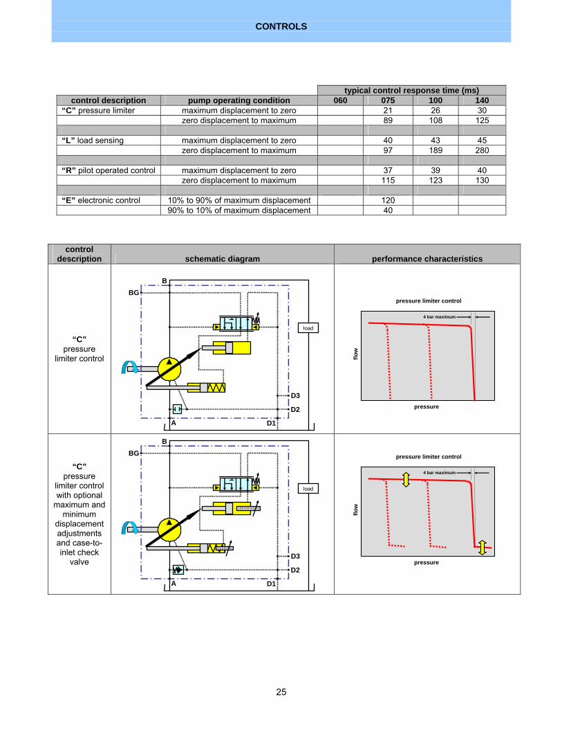
typical control response time (ms) control description pump operating condition 060 075 100 140
“C” pressure limiter maximum displacement to zero 21 26 30 zero displacement to maximum 89 108 125 “L” load sensing maximum displacement to zero 40 43 45 zero displacement to maximum 97 189 280 “R” pilot operated control maximum displacement to zero 37 39 40 zero displacement to maximum 115 123 130 “E” electronic control 10% to 90% of maximum displacement 120 90% to 10% of maximum displacement 40
control description schematic diagram performance characteristics
“C” pressure
limiter control
A D1
D2
D3
BGB
load
flow
pressure
pressure limiter control
4 bar maximum
“C” pressure
limiter control with optional
maximum and minimum
displacement adjustments and case-to-inlet check
valve
A D1
D2
D3
BGB
load
flow
pressure
pressure limiter control
4 bar maximum
CONTROLS
26
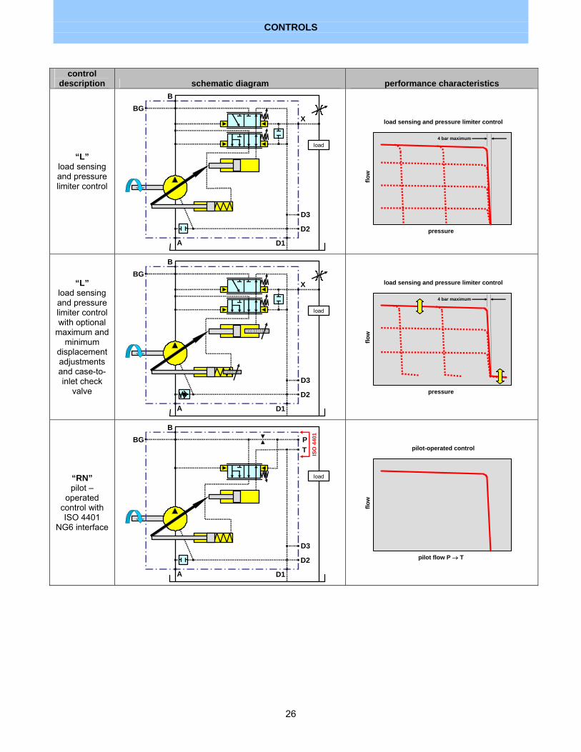
control description schematic diagram performance characteristics
“L” load sensing and pressure limiter control
A D1
D2
D3
BGB
X
load
flow
pressure
load sensing and pressure limiter control
4 bar maximum
“L” load sensing and pressure limiter control with optional
maximum and minimum
displacement adjustments and case-to-inlet check
valve
A D1
D2
D3
BGB
X
load
flow
pressure
load sensing and pressure limiter control
4 bar maximum
“RN” pilot –
operated control with ISO 4401
NG6 interface
A D1
D2
D3
BGB
load
PT ISO
440
1
flow
pilot flow P → T
pilot-operated control

CONTROLS
27
control description schematic diagram performance characteristics
“RN” pilot –
operated control with ISO 4401
NG6 interface and optional
maximum and minimum
displacement adjustments and case-to-inlet check
valve A D1
D2
D3
BGB
load
PT IS
O 4
401
flow
pilot flow P → T
pilot-operated control
“RH” pilot –
operated control with
remote control port “Z”
A D1
D2
D3
BGB
load
PT
Z
customer supplied
valve
flow
pilot flow Z → T
pilot-operated control
“RH” pilot –
operated control with
remote control port “Z” and
optional maximum and
minimum displacement adjustments and case-to-inlet check
valve A D1
D2
D3
BGB
load
PT
Z
customer supplied
valve
flow
pilot flow Z → T
pilot-operated control

CONTROLS
28
control description schematic diagram performance characteristics
“RM” pilot –
operated pressure
limiter control with vent port
“V”
A D1
D2
D3
BGB
load
V
flow
pressure
pilot-operated pressure limiter control
4 bar maximum
“RM” pilot –
operated pressure
limiter control with vent port
“V” and optional
maximum and minimum
displacement adjustments and case-to-inlet check
valve A D1
D2
D3
BGB
load
V
flow
pressure
pilot-operated pressure limiter control
4 bar maximum
“RE” pilot –
operated electro-
proportional pressure
limiter control
A D1
D2
D3
BGB
load
flow
pressure
pilot-operated pressure limiter control
4 bar maximum

CONTROLS
29
control description schematic diagram performance characteristics
“RE” pilot –
operated electro-
proportional pressure
limiter control with optional
maximum and minimum
displacement adjustments and case-to-inlet check
valve A D1
D2
D3
BGB
load
flow
pressure
pilot-operated pressure limiter control
4 bar maximum
“EY” integrated
digital electronic
control with case-to-inlet check valve
A D1
D2
D3
BGB
loadp
e
pe
ne
e d
amp
X
commandsoutputs
power
S
flow
pressure
integrated digital electronic control
4 bar maximum

“EY” INTEGRATED DIGITAL ELECTRONIC CONTROL SPECIFICATIONS
30
description specifications comments power supply voltage 9 to 36 vdc D.C. power supply (<5% ripple) (SAE J1455) power supply current 2.2 A maximum 1.1 A quiescent current ± 1.1 A input connector 19 pin MS threaded connector mating connector provided by Denison onboard power supply ±10 vdc
±10 mA maximum conditioned supply to power input command devices
input commands 0 to 10 vdc or 4 to 20 mA or
0 to 20 mA
displacement command, pressure limiter setting, and torque limiter setting
analog output signal 0 to 10 vdc 20 mA maximum
actual operating pump displacement or outlet pressure or speed or signal pressure – pc user interface selects output signal parameter
“enable” digital input 9 to 36 vdc (supply voltage)
input to enable the operation of the pump control - remove this input to disable the pump control
“ready” digital output 0 or 10 vdc 5 mA maximum
indicates the pump is ready for operation - control error exists if ready signal is not present
ramp 0 to 90 seconds pc user interface enables and sets the ramp hysteresis <2% of maximum displacement repeatability <1% of maximum displacement operating temperature -40 to +95 ºC pump inlet oil temperature serial communications port RS-232 DB9 connector –
Windows© pc connection to the user interface optional serial bus connector CAN compatible 4-pin EMI and RFI susceptibility 10 V/m maximum CE Mark environmental protection class IP65

MODEL CODE KEYSHEET
31
P1 075PS 01SR M5A C00 E100 PB M2 P1 mobile 280 bar XL Series
XL Series model code
PD industrial 280 bar XL Series P1 075PS 01SR M5A C00 E100 PB M2 045 45 cc/rev 060 60 cc/rev 075 75 cc/rev 100 100 cc/rev
maximum displacement
140 140 cc/rev type of product P1 075PS 01SR M5A C00 E100 PB M2 P open-circuit variable displacement mounting and ports P1075PS 01SR M5A C00 E100 PB M2 S SAE – inch mounting and inch ports A SAE – inch mounting, metric flange port threads, and BSP threaded ports M ISO – metric mounting and metric ports B ISO – metric mounting and BSP ports shaft P1 075PS 01SR M5A C00 E100 PB M2 01 SAE spline 02 SAE key 03 ISO/DIN spline 04 ISO key 05 SAE key (long extension) shaft seal P1 075PS 01SR M5A C00 E100 PB M2 S single shaft seal direction of shaft rotation P1 075PS 01SR M5A C00 E100 PB M2 R clockwise rotation L counter-clockwise rotation application P1 075PS 01SR M5A C00 E100 PB M2 S industrial (only available with PD prefix) M mobile (only available with P1 prefix) seal material P1 075PS 01SR M5A C00 E100 PB M2 5 fluorocarbon Viton design letter P1 075PS 01SR M5A C00 E100 PB M2 A current design series letter controls P1 075PS 01SR M5A C00 E100 PB M2 C0 pressure limiter 80 – 280 bar adjustment range C1 pressure limiter 20 – 80 bar adjustment range L0 load sensing 10 – 30 bar ∆P and pressure limiter 80 – 280 bar L1 load sensing 10 – 30 bar ∆P and pressure limiter 20 – 80 bar RN pilot operated control with ISO-4401 (NG 6) interface and shipping cover RH pilot operated control with vent port RM pilot operated pressure limiter control with mechanical adjustment and vent port RE pilot operated pressure limiter control with proportional electronic adjustment EY integrated digital electronic displacement and pressure control additional control options P1 075PS 01SR M5A C00 E100 PB M2 0 none T torque limiter (only available with electronic control “E”) port orientation P1 075PS 01SR M5A C00 E100 PB M2 E end ports S side ports T side ports with thru-drive
MODEL CODE KEYSHEET
32
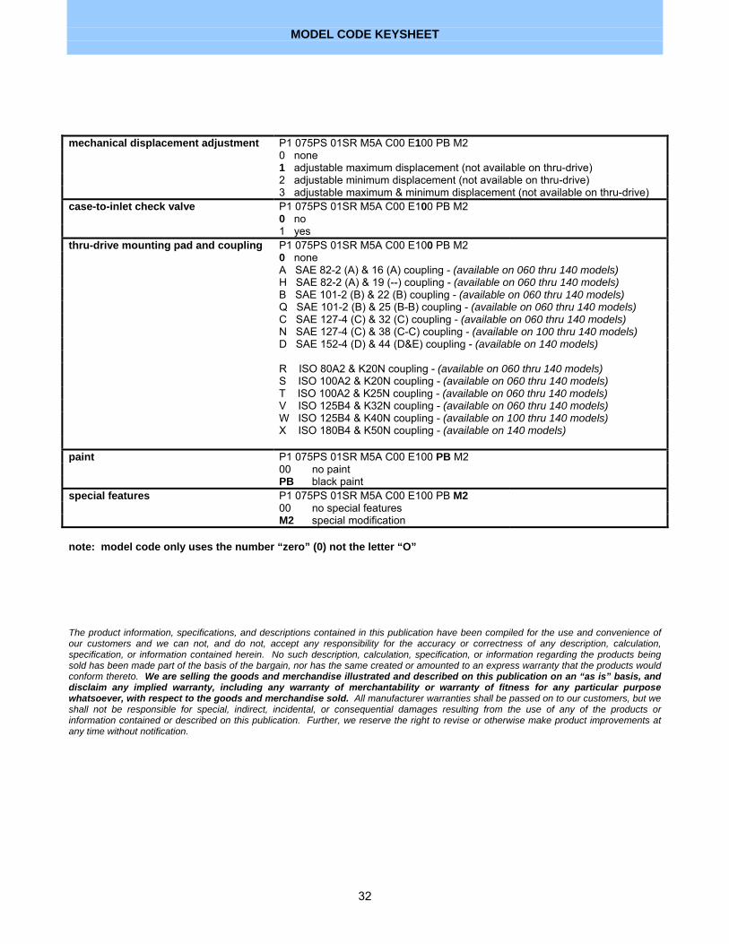
mechanical displacement adjustment P1 075PS 01SR M5A C00 E100 PB M2 0 none 1 adjustable maximum displacement (not available on thru-drive) 2 adjustable minimum displacement (not available on thru-drive) 3 adjustable maximum & minimum displacement (not available on thru-drive) case-to-inlet check valve P1 075PS 01SR M5A C00 E100 PB M2 0 no 1 yes thru-drive mounting pad and coupling P1 075PS 01SR M5A C00 E100 PB M2 0 none A SAE 82-2 (A) & 16 (A) coupling - (available on 060 thru 140 models) H SAE 82-2 (A) & 19 (--) coupling - (available on 060 thru 140 models) B SAE 101-2 (B) & 22 (B) coupling - (available on 060 thru 140 models) Q SAE 101-2 (B) & 25 (B-B) coupling - (available on 060 thru 140 models) C SAE 127-4 (C) & 32 (C) coupling - (available on 060 thru 140 models) N SAE 127-4 (C) & 38 (C-C) coupling - (available on 100 thru 140 models) D SAE 152-4 (D) & 44 (D&E) coupling - (available on 140 models) R ISO 80A2 & K20N coupling - (available on 060 thru 140 models) S ISO 100A2 & K20N coupling - (available on 060 thru 140 models) T ISO 100A2 & K25N coupling - (available on 060 thru 140 models) V ISO 125B4 & K32N coupling - (available on 060 thru 140 models) W ISO 125B4 & K40N coupling - (available on 100 thru 140 models) X ISO 180B4 & K50N coupling - (available on 140 models) paint P1 075PS 01SR M5A C00 E100 PB M2 00 no paint PB black paint special features P1 075PS 01SR M5A C00 E100 PB M2 00 no special features M2 special modification note: model code only uses the number “zero” (0) not the letter “O”
The product information, specifications, and descriptions contained in this publication have been compiled for the use and convenience of our customers and we can not, and do not, accept any responsibility for the accuracy or correctness of any description, calculation, specification, or information contained herein. No such description, calculation, specification, or information regarding the products being sold has been made part of the basis of the bargain, nor has the same created or amounted to an express warranty that the products would conform thereto. We are selling the goods and merchandise illustrated and described on this publication on an “as is” basis, and disclaim any implied warranty, including any warranty of merchantability or warranty of fitness for any particular purpose whatsoever, with respect to the goods and merchandise sold. All manufacturer warranties shall be passed on to our customers, but we shall not be responsible for special, indirect, incidental, or consequential damages resulting from the use of any of the products or information contained or described on this publication. Further, we reserve the right to revise or otherwise make product improvements at any time without notification.

WORLDWIDE SALES AND SERVICE LOCATIONS
33
For more information, please contact:
North America
Canada Parker Denison 160 Chisholm Drive Milton, Ontario L9T 3G9 Canada Tel : +1 (905) 693-3000 Fax : +1 (905) 876-1958
Central America &
South America Mexico, Central America,
South America, and Caribbean
Parker Denison 7400 NW 19th Street Suite A Miami, FL 33126, USA Tel: +1 (305) 470-8826 Fax: +1 (305) 470-8810
Asia-Pacific
Australia Parker Denison 41-43 St Hilliers Road P.O.Box 192 Auburn N.S.W. 2144, Australia Tel : +61 (2) 9646 5200 Fax : +61 (2) 9643 1305
Hong Kong Parker Denison Unit 6A, 33/F Cable TV Tower 9 Hoi Shing Road, Tsuen Wan NT, Hong Kong Tel : +852 2498 8381 Fax : +852 2499 1522
Japan Parker Denison 4-2-1 Tsujido-Shinmachi Fujisawa 251-0042, Japan Tel : +81 (466) 35-3050 Fax : +81 (466) 35-2019
China Parker Denison Room 8018, No. 601 Zhang Yang Road, Pudong New Area Shanghai 200120, P.R. China Tel: +86 (21) 58205042 / 34 Fax: +86 (21) 58205014
Singapore Parker Denison Blk 4012 Ang Mo Kio Ave 10, Unit #07-01D Techplace I Singapore 569628 Tel : +65 268 7840 Fax : +65 268 7847
Taiwan Parker Denison 6F-10, No. 79, Sec. 2 Roosevelt Rd, Taipei, Taiwan, ROC Tel : +886-2-23645101 Fax : +886-2-23639025
Europe
Austria Parker Denison Zweigniederlassung Linz Haibachstraße 69 4061 Pasching, Austria Tel : +43 (72 29) 48 87 Fax : +43 (72 29) 6 30 92
Benelux Parker Denison Pascalstraat 100 3316 GR Dordrecht, Holland Tel : +31 (78) 6543 070 Fax : +31 (78) 6175 755
Denmark Parker Denison Industrikrogen 2 2635 Ishöj, Denmark Tel : +45 (4371) 15 00 Fax : +45 (4371) 15 16
Finland Parker Denison Lokomec Polunmäenkatu 22 P.O. Box 116 33721 Tampere, Finland Tel : + 358 (3) 357 5100 Fax : + 358 (3) 357 5111
France Parker Denison 14 route du bois blanc BP 539 18105 Vierzon, France Tel : +33 (2) 48 53 01 20 Fax : +33 (2) 48 75 02 91
Great Britain Parker Denison Kenmore Road Wakefield 41, Industrial Park Wakefield, WF2 OXE West Yorkshire, England Tel : +44 (1924) 826 021 Fax : +44 (1924) 826 146
Germany Parker Denison Auf dem Sand 14 D 40721 Hilden, Germany Tel : +49 (0) 2103 / 940-3 Fax : +49 (0) 2103 / 940-558
Italy Parker Denison Via Le Europa 68 20090 Cusago (MI), Italy Tel : +39 (02) 90330-1 Fax : +39 (02) 90390694/5/6 Parker Denison Calzoni Via Caduti di Sabbiuno15/17 40011 Anzola dell'Emilia Bologna, Italy Tel : +39 (051) 6501611 Fax : +39 (051) 736221
Spain
Parker Denison Gomis 1 08023 Barcelona, Spain Tel : +34 (93) 253 1990 Fax : +34 (93) 211 6507
Sweden Parker Denison Sporregatan 13 213 77 - Malmö, Sweden Tel : +46 (40) 600 13 00 Fax : +46 (40) 600 13 50
Other European, Middle Eastern, and African
countries Parker Denison ATTN: Export Office 14 route du bois blanc BP 538 18105 Vierzon, France Tel : +33 (2) 48 53 01 20 Fax : +33 (2) 48 53 01 46
Parker Hannifin Hydraulic Pump Division
14249 Industrial Parkway Marysville, Ohio 43040 USA
phone: ...................... 937-644-3915 fax:............................ 937-642-3738
Call toll-free
800-551-5956 in North America
or visit www.denisonhydraulics.com
to locate a Parker Denison
representative near you
Copyright © 2004 Parker Denison All rights reserved. 11-30-04