hydraulic induced instability on a vertical service water …
TRANSCRIPT
HYDRAULIC INDUCED INSTABILITY ON A VERTICAL SERVICE
WATER PUMP: CASE HISTORY
R.F. Bosmans Bently Rotor Dynamics Research Corporation
Hi nden , Nevada 89423
The case history contained in this paper provides insight toward the mechanical and hydraulic behavior of a vertical pump. measurements on the rotor at or near the impeller area.
It clearly demonstrates the need for
INTRODUCTION
This case history reports the results of an analysis on a service water pump. This pump is typical o f the water pumps used throughout the power generation indus- try. Although little is known of the mechanical behavior of vertical pumps because of difficulty in modeling the rotor system, recent developments in the application of submersible proximity transducers have made possible the measurement o f pump dynamics under operating conditions.
The purpose of thjs study was to determine the proper selection and installa- tion of vibration-monitoring transducers as well as to measure the effects of imbalance, misalignment, and hydraulics on the performance and reliability of ver- tical pumps. In addition, the cause o f shaft failures on this pump was to be determined.
MACHINE DESCRIPTION
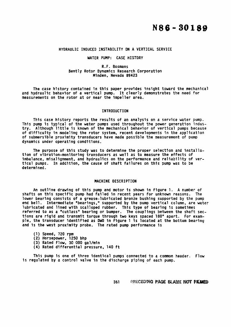
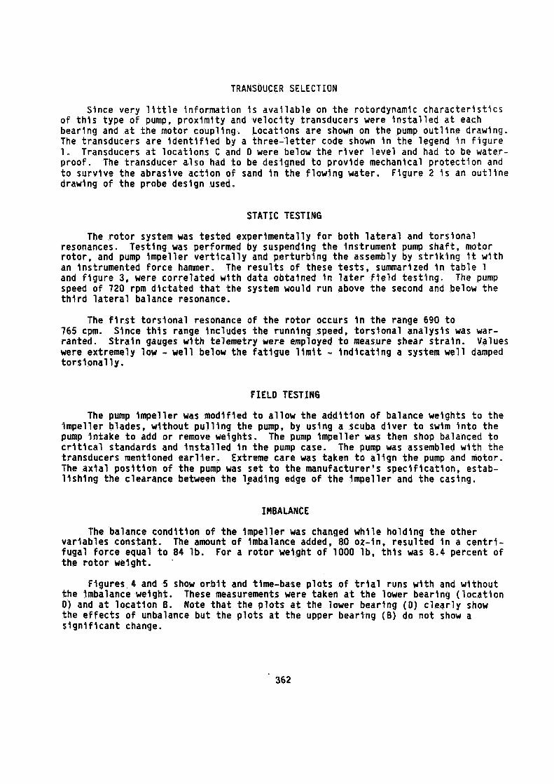
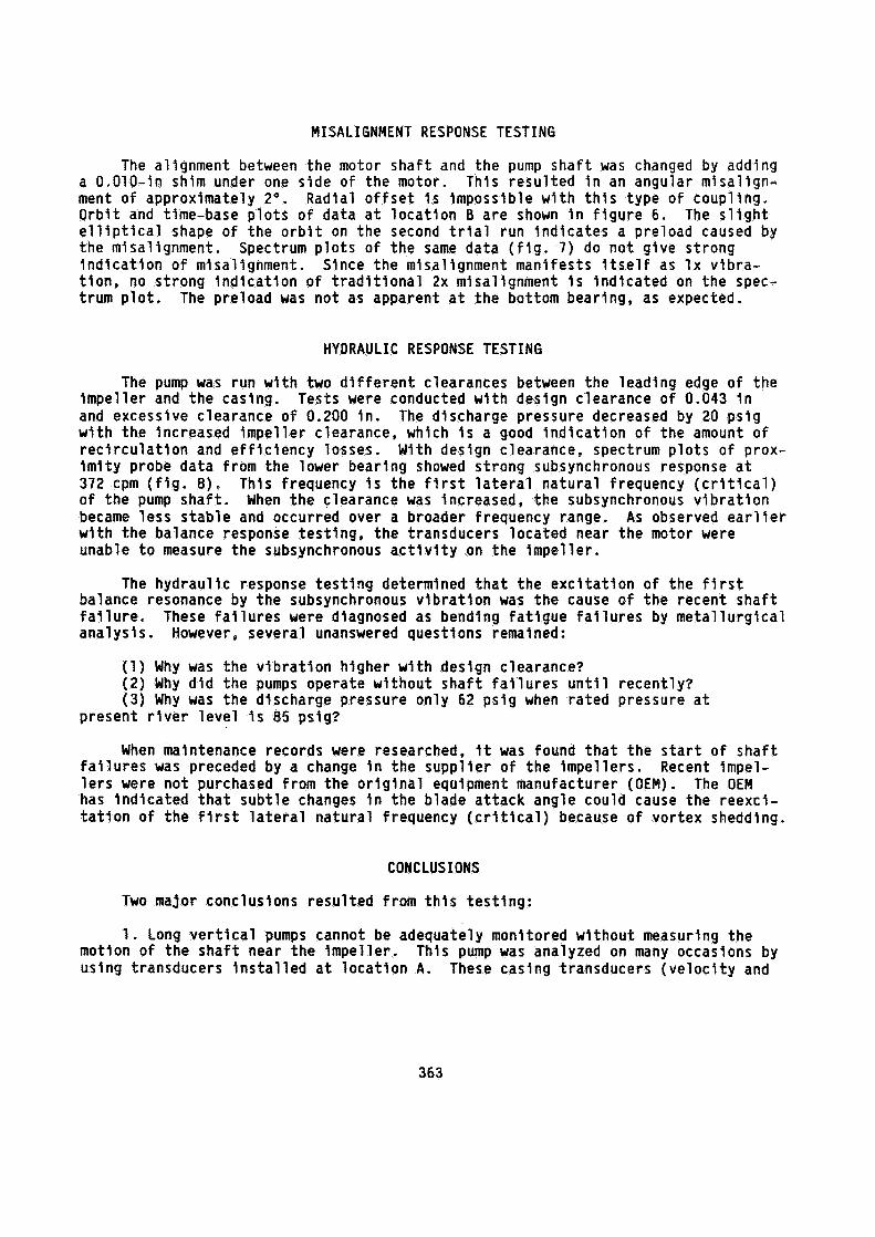
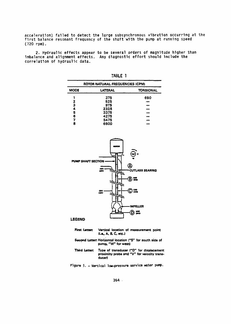
An outline drawing of this pump and motor is shown in figure I. A number of shafts on this specific pump had failed in recent years for unknown reasons. The lower bearing consists o f a grease-lubricated bronze bushing supported by the pump end bell. Intermediate "bearings," supported by the pump vertical column, are water lubricated and lined with scalloped rubber. This type of bearing is sometimes referred to as a "cutlass" bearing or bumper. tions are rigid and transmit torque through two keys spaced 180' apart. For exam- ple, the transducer identified as DWD in figure 1 is located at the bottom bearing and is the west proximity probe.
The couplings between the shaft sec-
The rated pump performance is
( 7 ) Speed, 720 rpm (2) Horsepower, 1250 bhp (3) Rated flow, 30 000 gal/min (4) Rated differential pressure, 140 ft
This pump is one of three identical pumps connected to a common header. Flow is regulated by a control valve in the discharge piping of each pump.
TRANSDUCER SELECTION
Since very l i t t l e informat ion i s ava i lab le on the rotordynamic charac ter is t i cs o f t h i s type o f pump, prox imi ty and ve loc i t y transducers were i n s t a l l e d a t each bearing and a t the motor coupling. Locations are shown on the pump ou t l i ne drawing. The transducers are i d e n t i f i e d by a th ree - le t te r code shown i n the legend i n f i g u r e 1. Transducers a t locat ions C and D were below the r i v e r l e v e l and had t o be water- proof. The transducer a.lso had t o be designed t o provide mechanical p ro tec t ion and t o survive the abrasive ac t ion o f sand i n the f lowing water. Figure 2 i s an ou t l i ne drawing o f the probe design used.
STATIC TESTING
The r o t o r system was tested experimentally f o r both l a t e r a l and to rs iona l resonances. Test ing was performed by suspending the instrument pump shaft , motor ro to r , and pump impel ler v e r t i c a l l y and per turb ing the assembly by s t r i k i n g i t w i t h an instrumented force hammer. The resu l t s o f these t e s t s , summarized i n tab le 1 and f i gu re 3 , were corre la ted w i th data obtained i n l a t e r f i e l d tes t ing . The pump speed o f 720 rpm d ic ta ted tha t the system would run above the second and below the t h i r d l a t e r a l balance resonance.
The f i r s t t o rs iona l resonance o f the r o t o r occurs i n the range 690 t o Since t h i s range includes the running speed, to rs iona l analysis was war- 765 cpm.
ranted. S t r a i n gauges w i t h telemetry were employed t o measure shear stra'ln. were extremely low - we l l below the fa t i gue l i m i t - i n d i c a t i n g a system we l l damped to rs iona l l y .
Values
FIELD TESTING
The pump impel ler was modified t o a l low the add i t ion o f balance weights t o the impel ler blades, wi thout p u l l i n g the pump, by using a scuba d iver t o sw im i n t o the pump in take t o add o r remove weights. The pump impel ler was then shop balanced t o c r i t i c a l standards and i n s t a l l e d i n the pump case. The pump was assembled w i th the transducers mentioned e a r l i e r . Extreme care was taken t o a l i g n the pump and motor. The a x i a l pos i t i on o f the pump was set t o the manufacturer's spec i f i ca t ion , estab- l i s h i n g the clearance between the laading edge o f the impel ler and the casing.
IMBALANCE
The balance condi t ion o f the impel ler was changed wh i le ho ld ing the other var iables constant. The amount o f imbalance added, 80 oz-in, resul ted i n a c e n t r i - fugal force equal t o 84 l b . For a r o t o r weight o f 1000 lb , t h i s was 8,4 percent o f the r o t o r weight. .
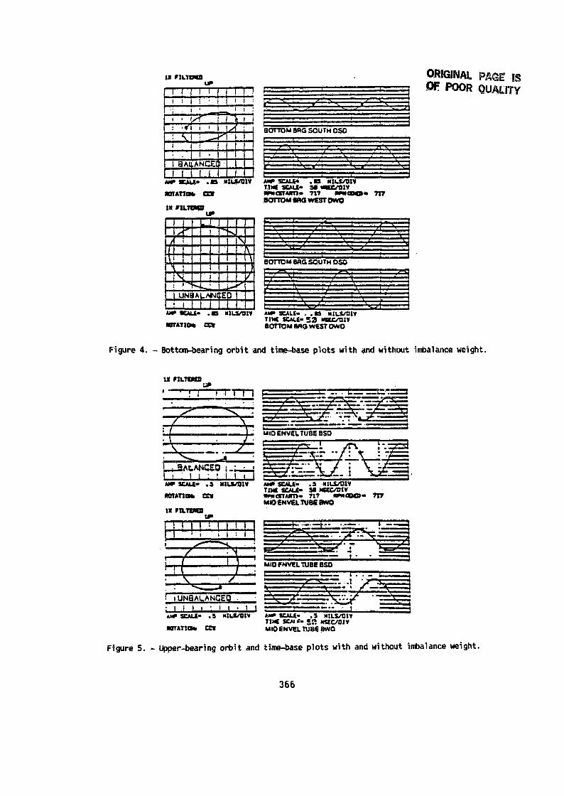
Figures 4 and 5 show o r b i t and time-base p l o t s o f t r i a l runs w i t h and wi thout the imbalance weight. 0) and a t l oca t i on 8. Note t h a t the p l o t s a t the lower bearing ( 0 ) c l e a r l y show the e f fec ts o f unbalance but the p lo t s a t the upper bearing (8) do not show a s i g n i f i c a n t change.
These measurements were taken a t the lower bearing ( l oca t i on
362
MISALIGNMENT RESPONSE TESTING
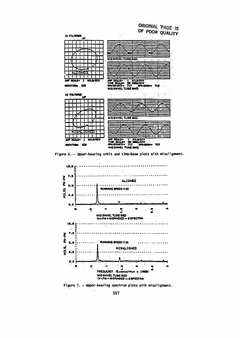
The alignment between the motor shaf t and the pump shaf t was changed by adding a 0.010-in shim under one side o f the motor. This resul ted i n an angular m’isalign- ment o f approximately 2 O . Radial o f f s e t i s impossible w i t h t h i s type o f coupling. Orb i t and time-base p lo t s o f data a t loca t ion 6 are shown i n f i gu re 6 . The s l i g h t e l l i p t i c a l shape o f the o r b i t on the second t r i a l run ind icates a preload caused by the misalignment. Spectrum p lo ts o f the same data ( f i g . 7 ) do not give strong ind i ca t i on o f misalignment. Since the misalignment manifests i t s e l f as l x v ibra- t ion , no strong ind i ca t i on o f t r a d i t i o n a l 2x misalignment i s ind icated on the spec- trum p l o t . The preload was not as apparent a t the bottom bearing, as expected.
HYDRAULIC RESPONSE TESTING
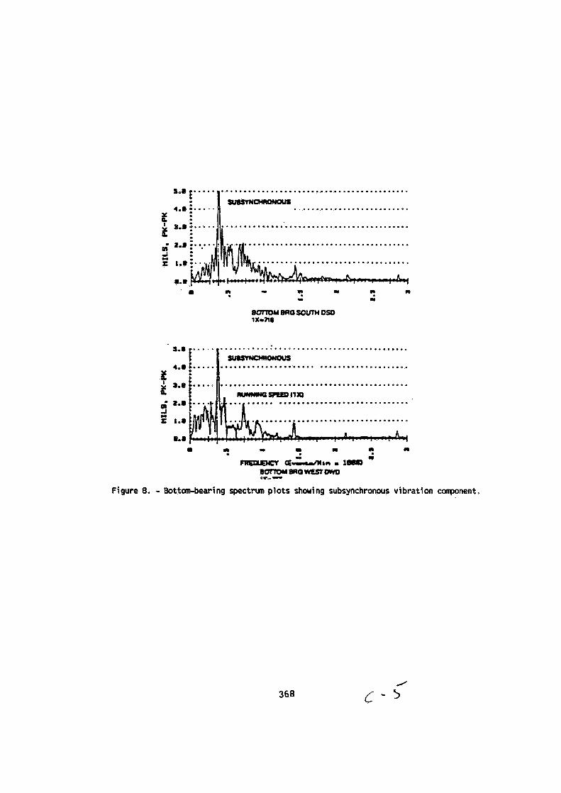
The pump was run w i t h two d i f f e r e n t clearances between the leading edge o f the impel ler and the casing. and excessive clearance o f 0.200 in . w i th the increased impel ler clearance, which i s a good ind i ca t i on o f the amount o f r e c i r c u l a t i o n and e f f i c i ency losses . With design clearance, spectrum p lo ts o f prox- i m i t y probe data f r o m the lower bearing showed strong subsynchronous response a t 372 cpm ( f i g . 8) . This frequency i s the f i r s t l a t e r a l natura l frequency ( c r i t i c a l ) o f the pump shaft . When the clearance was increased, the subsynchronous v ib ra t i on became less s tab le and occurred over a broader frequency range. As observed e a r l i e r w i t h the balance response tes t ing , the transducers located near the motor were unable t o measure the subsynchronous a c t i v i t y on the impel ler .
balance resonance by the subsynchronous v jb ra t i on was the cause o f the recent shaf t f a i l u r e - analysis. However, several unanswered questions remained:
T e s t s were conducted w i t h design clearance o f 0.043 i n The discharge pressure decreased by 20 ps ig
The hydraul ic response t e s t i n g determined t h a t the exc i ta t i on o f the f i r s t
These f a i l u r e s were diagnosed as bending fa t igue f a i l u r e s by meta l lu rg ica l
(1) Why was the v ib ra t i on higher w i t h design clearance? (2) Why d i d the pumps operate wi thout shaf t f a i l u r e s u n t i l recent ly? ( 3 ) Why was the discharge pressure only 62 ps ig when rated pressure a t
present r i v e r l eve l i s 85 pstg?
When maintenance records were researched, i t was found tha t the s t a r t o f sha f t f a i l u r e s was preceded by a change i n the suppl ier o f the impel lers. l e r s were not purchased from the o r i g i n a l equipment manufacturer (OEM). has ind icated tha t subt le changes i n the blade at tack angle could cause the reexci- t a t i o n o f the f i r s t l a t e r a l natura l frequency ( c r i t i c a l ) because o f vortex shedding.
Recent impel- The OEM
CONCLUSIONS
Two major conclusions resul ted from t h i s tes t ing :
1. Long v e r t i c a l pumps cannot be adequately monitored without measuring the motion o f the shaf t near the impel ler . using transducers i n s t a l l e d a t loca t ion A.
T h i s pump was analyzed on many occasions by These casing transducers ( ve loc i t y and
363
acceleration) failed to detect the large subsynchronous vibration occurring at the first balance resonant frequency of the shaft with the pump at running speed (720 rpm).
2. Hydraulic effects appear to be several orders of magnitude higher than imbalance and alignment effects. correlation of hydraulic data.
Any diagnostic effort should include the
TABLE 1
ROTOR NATURAL FREQUENCIES (CPM)
MODE LATERAL TORSIONAL
PUMP s n m
LEGEND
375 525 975
2325 3375 4275 5475 6600
'SE
BEARING
First hnsr: Vertical location of measurement point (i.s. A, B, C. arc.)
Second Letter: Horizontal location (5" for south side of pump, "W" for west)
Third h a c Type of transducer YO" for displacement proximity probe and "V" for velocity trans- duced
Figure 1. - Vertical h+pressure service water PW.
3 64

318.24 UNF*ZA
N E I N Q AND UNIONS AS REQUIRED
Figure 2. - Waterproof proximity probe transducer.
12 Lateral natural frequency test, / - hanging fran turbine room crane; impeller i n a i r
I --- Actual mode based on measurement
under normal operation condition
\ Q
6
4
3
'c /
i 0
10
9
a
7
I
- -1 '1
Ozflaction (Normalitad)
40'
30'
Length o f Shaft (m
20'
IO'
09
Figure 3. - Rode #2 a t 525 cpm.
365
m A T l # Ul
I
Figure 4. - Bottan-bearing orbit and time-base plots with and without i h l a n c e weight.
. . .
ROTATIOC G U
Figure 5. - Upper-bearing orbit and time-base plots with and without i&alance weight.
366
t 1
Figure 6. - Upper-bearing orbit and time-base plots with misaligtnnent. ................................................
"-@ I 7.s ...............................................
X
r a m u Q ~ f t x ,
n .r a a 1 -
I 1
rrtOfMlEfN8eeSO IXmIIe WllftKiLO - L SP-A
l D . 0 ~ ................................................ 7.s ................................................. * . I
............... ..................
367
- ...... ..........................
.................................... ........................
a .) N N
? - - m ?
B ~ M 8 R ~ s o L m ( D S D 1x-7lr
- w€ED t1m ..................................
a ? 0 a 5
B~maryEsIDwD
0 ? I)
a&," I 1-
e*--
Figure 8. - Bottan-bearing spectrun plots showing subsynchronous vibration component.
368