hydraulic division fs1 series fs1 series ...fs1 series 3/8 the pressure drop of these strainers is...
TRANSCRIPT

HYDRAULIC DIVISION FS1 SERIES
FS1 SERIESSUCTION STRAINERS
TECHNICAL INFORMATION
FS1 suction strainers are designed for direct mounting on the suction line,immersed in the oil tank, to protect the pump from coarse contamination.
FS1 SERIES 1/8
HYDRAULIC SYMBOL
CONNECTION PORTS from G 3/8" to G 4"
MATERIALS: Threaded connector: Polyammide reinforced End cap: Zinc plated steelInternal core: Zinc plated steelBypass valve: Polyammide reinforced
FILTER MEDIA: Stainless steel wire mesh (125 µm and 60 µm)Zinc plated steel wire mesh (250 µm)
BYPASS VALVE: setting 0,35 bar
DIFFERENTIAL COLLAPSE PRESSURE: 1 bar (ISO 2941)
OPERATING TEMPERATURE RANGE: -20°C to 100°C
FLUID COMPATIBILITY: Full with HH-HL-HM-HV (acc. to ISO 2943).
For use with other fluid applications please contact Filtrec CustomerService ([email protected]).
FS1 SERIES 2/8
�
�
��
���������� ��
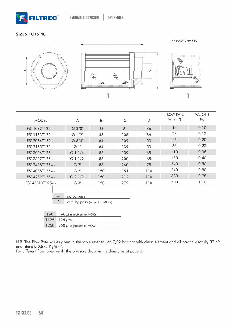
SIZES 10 to 40
N.B. The Flow Rate values given in the table refer to Dp 0,02 bar bar with clean element and oil having viscosity 32 cStand density 0,875 Kg/dm3.For different flow rates verify the pressure drop on the diagrams at page 3.
HYDRAULIC DIVISION FS1 SERIES
FS110B2T125--- G 3/8" 46 91 36 16 0,10
FS111B3T125--- G 1/2" 46 106 36 26 0,12
FS120B4T125--- G 3/4" 64 109 50 45 0,20
FS121B5T125--- G 1" 64 139 50 65 0,22
FS130B6T125--- G 1 1/4" 86 139 65 110 0,36
FS133B7T125--- G 1 1/2" 86 200 65 150 0,40
FS134B8T125--- G 2" 86 260 75 240 0,50
FS140B8T125--- G 2" 150 151 110 240 0,80
FS142B9T125--- G 2 1/2" 150 212 110 380 0,98
FS143B10T125--- G 3" 150 272 110 500 1,10
MODEL A B C D
FLOW RATEl/min (*)
WEIGHTKg
T60 60 µm (subject to MOQ)
T125 125 µmT250 250 µm (subject to MOQ)
--- no by-passB with by-pass (subject to MOQ)

FS1 SERIES 3/8
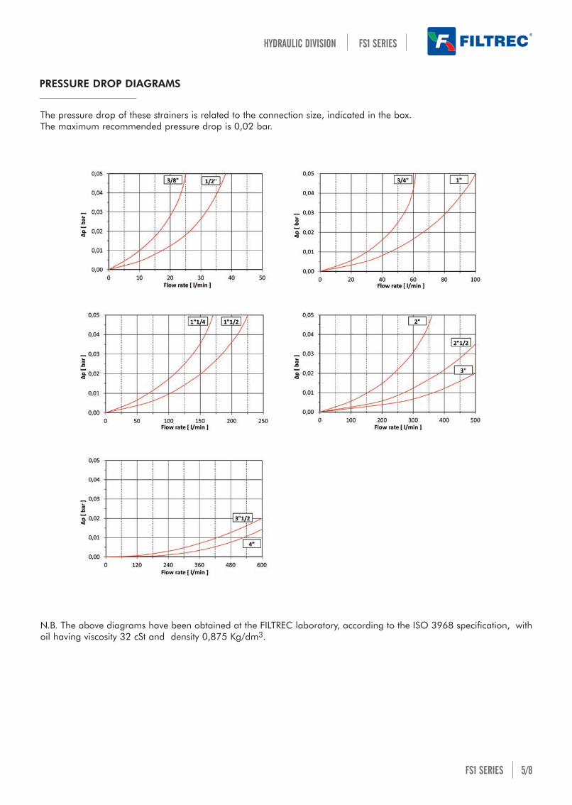
The pressure drop of these strainers is related to the connection size, indicated in the box. The maximum recommended pressure drop is 0,02 bar.
N.B. The above diagrams have been obtained at the FILTREC laboratory, according to the ISO 3968 specification, withoil having viscosity 32 cSt and density 0,875 Kg/dm3.
PRESSURE DROP DIAGRAMS
HYDRAULIC DIVISION FS1 SERIES

DC
A B
SIZES 50 to 91
FS1 SERIES 4/8
HYDRAULIC DIVISION FS1 SERIES
FS150B2T125 G 3/8" 54 83 27 16 0,12
FS150B3T125 G 1/2" 54 83 27 26 0,12
FS160B3T125 G 1/2" 73 104 34 26 0,24
FS160B4T125 G 3/4" 73 104 34 45 0,24
FS162B5T125 G 1" 73 148 50 65 0,28
FS179B5T125 G 1" 102 110 60 65 0,35
FS170B6T125 G 1 1/4" 102 155 60 110 0,44
FS170B7T125 G 1 1/2" 102 155 60 150 0,50
FS173B7T125 G 1 1/2" 102 195 60 150 0,50
FS176B7T125 G 1 1/2" 102 228 60 240 0,60
FS176B8T125 G 2" 102 228 70 240 0,60FS180B8T125 G 2" 130 202 98 250 0,80FS180B9T125 G 2 1/2" 130 202 98 380 0,8
FS183B9T125 G 2 1/2" 130 235 98 380 1,00
FS186B10T125 G 3" 130 279 98 500 1,20
FS190B11T125 G 3 1/2”" 178 390 140 600 2,60
FS191B12T125 G 4" 178 440 140 600 3,00
MODEL A B C D
FLOW RATEl/min (*)
WEIGHTKg
T60 60 µm (subject to MOQ)
T125 125 µmT250 250 µm (subject to MOQ)
N.B. The Flow Rate values given in the table refer to Dp 0,02 bar with clean element and oil having viscosity 32 cSt anddensity 0,875 Kg/dm3.For different flow rates verify the pressure drop on the diagrams at page 5.
FS1 SERIES 5/8
The pressure drop of these strainers is related to the connection size, indicated in the box. The maximum recommended pressure drop is 0,02 bar.
N.B. The above diagrams have been obtained at the FILTREC laboratory, according to the ISO 3968 specification, withoil having viscosity 32 cSt and density 0,875 Kg/dm3.
PRESSURE DROP DIAGRAMS
HYDRAULIC DIVISION FS1 SERIES

FS1 SERIES 7/8
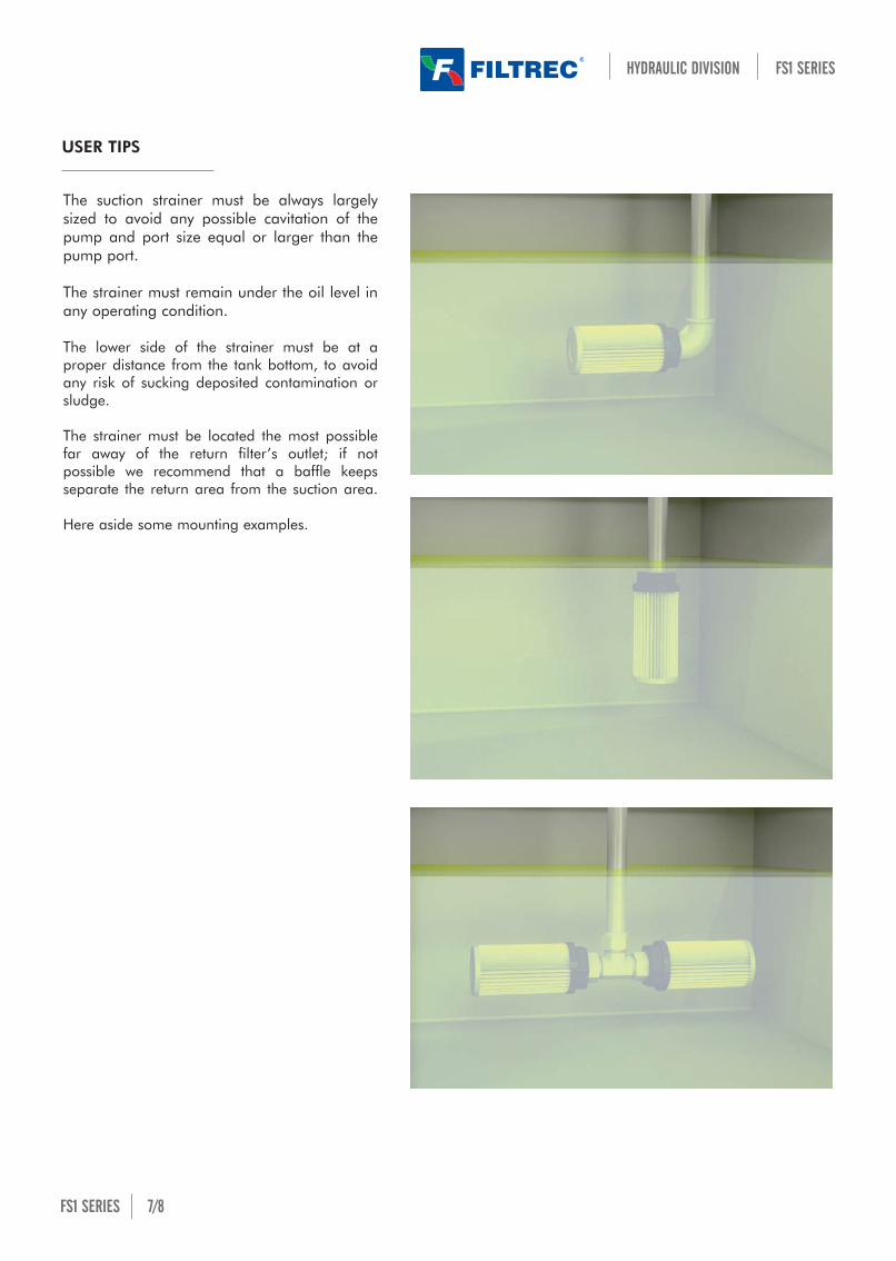
The suction strainer must be always largelysized to avoid any possible cavitation of thepump and port size equal or larger than thepump port.
The strainer must remain under the oil level inany operating condition.
The lower side of the strainer must be at aproper distance from the tank bottom, to avoidany risk of sucking deposited contamination orsludge.
The strainer must be located the most possiblefar away of the return filter’s outlet; if notpossible we recommend that a baffle keepsseparate the return area from the suction area.
Here aside some mounting examples.
USER TIPS
HYDRAULIC DIVISION FS1 SERIES

CT1
2-r
ev.0
0-0
1/2
0
Technical information may change without notice
HYDRAULIC DIVISION FS1 SERIES
FS1 SERIES 8/8www.filtrec.com