hydraulic cylinder s - uzun hidrolik 6022.pdfuzun hidrolik san ve tic a.s. 2 hydraulic cylinders...
TRANSCRIPT

UHSN
Nominal Pressure 250 Bar (25MPa)
ISO 6022
Contact : Istanbul Deri OSB. Karadeniz Cad.
13-2 Parsel No : 11
Orhanlı/TUZLA/ISTANBUL/TURKEY
Phone : (0216) 394 17 36-37
Fax :(0216) 394 22 92
Mail : [email protected]
Web: www.uzunhidrolik.com
HYDRAULIC CYLINDERS

UZUN HIDROLIK SAN ve TIC A.S. 2
HYDRAULIC CYLINDERS
Technical Data
The installation dimensions and types of mounting of the cylinders comply with the standarts DIN 24333 and ISO
6022.
Mounting Types : 6
Piston : Ø 40 – 200 mm
Piston Rod : Ø 25 – 140 mm
Stroke : max 3000 mm (Special stroke length deviating from standard to max. 9000 mm available on
request at any time, but depends on the piston Ø, piston rod Ø and the mounting position)
Nominal Pressure : 250 bar
Test Pressure : 375 bar
The specified operating pressures apply to applications with shock-free operation with regard to excess pressure and/
or external loads.
Hydraulic Fluid : DIN 51524 HL, HLP
Polyol-Ester : HFD-U
Hydraulic Fluid Temperature Range:
HL, HLP : (-40°C) – (+120°C)
HFD-U : (-40°C) – (+120°C)
Fluid temperature range : (-40°C) – (+120°C)
Viscosity range: 20 – 380 mm²/s ( can be higher by lower temperature)
Paint: Hydraulic cylinders are primered with a coating of min. 40 µm + 40 µm topcoat RAL 5010. Paint colors may
vary according to demand. Other colors upon request.
The paint and primer coat coding order information will be given as additional information.
Notice : The sketches can vary from real application . Please contact us for any related question

UZUN HIDROLIK SAN ve TIC A.S. 3
ENCODING ORDER
Examples of Coding :
UHSN-S-S-MP5-100/56-500-P-0/3-C-3-G-A-TF-W, Paint: RAL 5010
Remarks :
1) In special cylinders (UHSN-S-X- ...) size may vary.
2) Unless otherwise stated 0/0 valve connections, ventilation is 3/3.
3) Max. available stroke length page 4 and admissible stroke length observe page 15 and 16

UZUN HIDROLIK SAN ve TIC A.S. 4
Note : Theoretical force ( efficiency not taken into account. )
Tolerances according to ISO 6020-1
Stroke Tolerance Tolerance Tolerance Tolerance Tolerance Tolerance Tolerance
≤ 1250 ± 2 ± 1,5 ± 1,5 ± 2 ± 2 ± 1,5 2
1250 - 3149 ± 4 ± 3 ± 3 ± 4 ± 4 ± 3 5
3150 - 8000 ± 8 ± 5 ± 5 ± 8 ± 8 ± 5 8
MF3
Stroke
Tolerances
¹ : Stroke length included ² : No Standardized
XV²
MT4
ZP²
MF4
XC²
MP3
XO²
MP5
XS¹ ²
MS2
Installation
Dimensions
Mounting Types
WC

UZUN HIDROLIK SAN ve TIC A.S. 5
MOUNTING TYPE OVERVIEW
CYLINDER COMMON PARTS

UZUN HIDROLIK SAN ve TIC A.S. 6
BASIC VERSION
MOUNTING TYPE : ALL UHSN-S-S
AL
Ø
MM
ØKK A NV ØD ØDA ØD4
EE
7)
EE
7)PJ WA X1 Y ZB
25 19
28 22
32 27
36 30
40 32
45 36
50 41
56 46
63 50
70 60
80 65
90 75
90 75
100 85
100 85
110 95
110 95
125 110
125 110
140 120
18 41 83 282
* Ø AL : Piston Ø * Ø MM : Piston rod Ø * Bleeding : With view to the piston rod, the position is offset
by 90° in relation to the line connection (clockwise) * ØD4 max. 1 mm deep ³ : Piston Ø not standardized
40 ³ M20 x 1,5 28 88 50 34 G1/2 M22 x 1,5 120
690
756
185
194
220
305
348
395
442
520
580
617
98
112
120
134
153
166
48,5
56,5
69,5
82
100,5
109,5
129,5
143,5
150,5
18
21
24
27
31
31
35
40
40
M42 x 2
M42 x 2
M42 x 2
120
133
155
171
205
219
235
M22 x 1,5
M27 x 2
M27 x 2
M33 x 2
M33 x 2
M42 x 2
264
278
G1/2
G3/4
G3/4
G1
G1
G11/4
G11/4
G11/4
G11/4
34
42
42
47
47
58
58
58
58
85
90
95
105
265
292
306
65
78
100
125
150
170
190
102
120
145
170
206
226
220
245
* S : Stroke * For flange connection , see separate table on pages 12 and 13
160
180
200
M27 x 2
M33 x 2
M42 x 2
M48 x 2
M64 x 3
M72 x 3
M80 x 3
50
63
80
100
125
140
112
M90 x 3
M100 x 3
36
45
56
63

UZUN HIDROLIK SAN ve TIC A.S. 7
MOUNTING TYPE : MP3 – MP5
MP3 ;
MP5 ;
AL
Ø
MM
ØKK A NV ØD ØDA ØD4
EE
7)
EE
7)WA X1 PJ Y
CD
H9
CX
H7EP
EW
h12
EX
h12L LT L1 MR MS M1 XC X0
25 19
28 22
32 27
36 30
40 32
45 36
50 41
56 46
63 50
70 60
80 65
90 75
90 75
100 85
100 85
110 95
110 95
125 110
125 110
140 120
* Bleeding : With view to the piston rod, the poisiton is offset by 90° in relation to the line connection (clockwise)
144 194
M100 x 3 112 306 245 58 G11/4 M42 x 2 27840 151 220
M90 x 3 105 292 220 58 G11/4 M42 x 2 26440
110 166
M80 x 3 95 265 190 58 G11/4 M42 x 2 23535 130 185
M72 x 3 90 226 170 58 G11/4 M42 x 2 21931
82 134
M64 x 3 85 206 150 47 G1 M33 x 2 20531 101 153
M48 x 2 63 170 125 47 G1 M33 x 2 17127
M27 x 2 13321 56,5 112
M42 x 2 56 145 100 42 G3/4 M27 x 2 15524 69,5 120
41 83
M27 x 2 36 102 70 34 G1/2 M22 x 1,5 12018 48,5 98
M20 x 1,5 28 88 50 34 G1/2 M22 x 1,5 12018
Dimensions MP3 and MP5
32 32 32 282 282
*AL : PistonØ *MM : Piston rod * S : Stroke * ³ : Piston Ø not standardized *7) For flange connection, see separate table on pages 12 and 13 *D4 max. 1 mm deep
40 ³ 25 25 22 25 25 53 53 8
690
756
617
690
756
305
348
395
442
520
580
617
305
348
395
442
520
580
40
50
63
71
90
100
112
129
145
40
50
63
71
90
100
112
129
145
16
20
20
40
50
63
71
90
100
112
8
8
10
12
16
16
129
145
61
74
90
102
124
149
150
180
206
61
74
90
102
124
149
150
180
206
100
110
125
32
40
50
63
80
90
100
32
40
50
63
80
90
110
125
27
32
40
52
66
72
84
88
102
32
40
50
63
80
90
100
110
125
160
180
200
32
40
50
63
80
90
100
50
63
80
100
125
140
110
125
M33 x 2 45 120 78 42 G3/4

UZUN HIDROLIK SAN ve TIC A.S. 8
MOUNTING TYPE : MF3
UHSN-T-S-MF3
AL
Ø
MM
ØKK A NV ØD ØDA ØD4
EE
7)
EE
7)Y PJ X1
ØRD
f8
ØFB
H13
FC
js13NF PK
UC
Ø-1VD WA WC ZB ZM &
25 19
28 22
32 27
36 30
40 32
45 36
50 41
56 46
63 50
70 60
80 65
90 75
90 75
100 85
100 85
110 95
110 95
125 110
125 110
140 120
18
18
21
24
27
31
31
35
* Bleeding : With view to the piston rod, the poisiton is offset by 90° in relation to the line connection (clockwise)
*AL : Piston Ø *MM : Piston rod Ø ³ : Piston Ø not standardized * For main dimensions, see page 6 * S : Stroke *7) For flange connection, see separate table on pages 12 and 13
40 ³ 52 11 115 25 120 138 4 2283 230 286 45
511
551
605
718220
244
274
305
430
40
45
25
28
32
36
40
40
440
5
5
360
155
175
210
Dimensions MF3
45
45
45
45
45
45
45
45
550
316
357
395
439340
396
467
40
13,5 132 120 22
25
28
32
36
36
250
290
330
4
4
4
5
5
5
155
13,5
17,5
150
180
133
160
133 56,545
M42 x 2 56 145 100 42 G3/4 M27 x 2 155 69,5
112
120
82
200
63
75
90
110
132
145
160
50
63
80
100
125
140
200
M33 x 2 120 78 42
134
153
G3/4
98
M27 x 2
41
M27 x 2 36 102 70 34 G1/2 M22 x 1,5 120 48,5
M20 x 1,5 28 88 50 34 G1/2 M22 x 1,5 120
M64 x 3 85 206 150 47 G1 M33 x 2 205 100,5
M48 x 2 63 170 125 47 G1 M33 x 2 171 22
22
212
250
171
205
109,5
M80 x 3 95 265 190 58 G11/4 M42 x 2 235 129,5
M72 x 3 90 226 170 58 G11/4 M42 x 2 219166
M100 x 3 112 306 245 58 G11/4 M42 x 2 278 150,5
185 235
33 385 56
26
26
285
315 45
355 50 264
219
278
652 45180 M90 x 3 M42 x 2 33105 292 220 58 G11/4 194 264 143,5 185 410 5 40 45 510

UZUN HIDROLIK SAN ve TIC A.S. 9
MOUNTING TYPE : MF4
AL
Ø
MM
ØKK A NV ØD ØDA ØD4
EE
7)
EE
7)Y PJ WA X1 ZB
ØBA
H8
ØFB
H13
FC
js13
NF
js 13
UC
Ø-1VA ZP &
25 19
28 22
32 27
36 30
40 32
45 36
50 41
56 46
63 50
70 60
80 65
90 75
90 75
100 85
100 85
110 95
110 95
125 110
125 110
140 120
*AL : PistonØ *MM : Piston rodØ *S : Stroke * ³ : Piston Ø not standardized *7)For flange connection, see separate table on pages 12 and 13
*Bleeding : With view toto the piston rod, the positon is offset by 90° in relation to the line connection (clockwise)
40 ³ 52 11 115 25 5 250138 45
45
45
45
45
45
45
45
45
45
265
298
332
371
430
Dimensions MF4
465
505
550
596
4
4
5
5
6
5
7
10
10
45
50
56
155
175
210
250
290
325
360
25
28
32
36
40
40
405
440
132
150
180
212
250
280
315
350
385
13,5
13,5
17,5
22
22
26
26
33
33
160
180
200
63
75
90
110
132
145
160
50
63
80
100
125
140
185
200
M33 x 2 45 120 78 42 G3/4
4183 282
M27 x 2 36 102 70 34 G1/2 M22 x 1,5 120 18 48,598 305
M20 x 1,5 28 88 50 34 G1/2 M22 x 1,5 120 18
M27 x 2 133 21 56,5112 348
M42 x 2 56 145 100 42 G3/4 M27 x 2 155 24 69,5120 395
82134 442
M64 x 3 85 206 150 47 G1 M33 x 2 205 31 100,5153 520
M48 x 2 63 170 125 47 G1 M33 x 2 171 27
109,5166 580
M80 x 3 95 265 190 58 G11/4 M42 x 2 235 35 129,5185 617
M72 x 3 90 226 170 58 G11/4 M42 x 2 219 31
143,5194 690
M100 x 3 112 306 245 58 G11/4 M42 x 2 278 40 150,5220 756
M90 x 3 105 292 220 58 G11/4 M42 x 2 264 40

UZUN HIDROLIK SAN ve TIC A.S. 10
MOUNTING TYPE : MT4
UHSN-T-S-MT4
AL
Ø
MM
ØKK A NV ØD ØDA ØD4
EE 7)
EE 7)
Y PJ WA X1 BD PK rTD
f8
TL
js16
TM
h13UV
S
min.
XV
stan.
XV
min.
XV
max.
ZB
max.ZM
25 19
28 22
32 27
36 30
40 32
45 36
50 41
56 46
63 50
70 60
80 65
90 75
90 75
100 85
100 85
110 95
110 95
125 110
125 110
140 120
* Bleeding : With view to the piston rod, the position is offset by 90° in relation to the line connection (clockwise)
* AL : PistonØ * MM : Piston rodØ ³ : Piston Ø not standardized * S : Stroke * 7) Flange connection, see separate table on pages 12 and 13
40 ³ 38 120 0,8 25 15 11 50 32
120
134
153
166
185
154
171,5
189
218
240,5
1
1
2
Dimensions MT4
467
510
550
194
220
244
274
305
340
396
430
270
291,5
322,5
98
112
110 140 1118 83 230
135,5
3
1
19
44
50
56
155
180
220
255
305
350
400
440
465
77
92
97
130
150
180
210
255
290
330
37
42
47
57
67
72
360
385
45
49
52
61
75
70
65
69
73
11
13,5
17,5
22
26
30
33
40
40
100
115
125
17,5
20
25
30
35
42,5
52,5
32
40
50
63
80
90
57,5
62,5
0,8
1
1
1,2
1,2
1,5
1,5
1,5
1,5
120
133
155
171
205
219
235
264
278
160
180
200
38
48
58
78
98
118
128
50
63
80
100
125
140
138
178
M33 x 2 45 120 78 42 G3/4
41
M27 x 2 36 102 70 34 G1/2 M22 x 1,5 120 18 48,5
M20 x 1,5 28 88 50 34 G1/2 M22 x 1,5 120 18
M27 x 2 133 21 56,5
M42 x 2 56 145 100 42 G3/4 M27 x 2 155 24 69,5
82
M64 x 3 85 206 150 47 G1 M33 x 2 205 31 100,5
M48 x 2 63 170 125 47 G1 M33 x 2 171 27
109,5
M80 x 3 95 265 190 58 G11/4 M42 x 2 235 35 129,5
M72 x 3 90 226 170 58 G11/4 M42 x 2 219 31
143,5
M100 x 3 112 306 245 58 G11/4 M42 x 2 278 40 150,5
M90 x 3 105 292 220 58 G11/4 M42 x 2 264 40
UZUN HIDROLIK SAN ve TIC A.S. 11
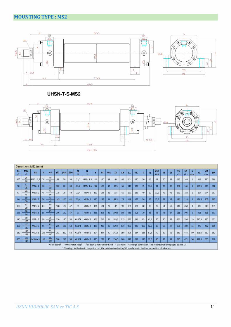
MOUNTING TYPE : MS2
UHSN-T-S-MS2
AL
Ø
MM
ØKK A NV ØD ØDA ØD4
EE 7)
EE 7)
Y PJ WA X1 LH L1 PK T T1ØSB
H13TT ST
TS
js13
US
Ø-1
S
min.XS
ZB
max.ZM
25 19
28 22
32 27
36 30
40 32
45 36
50 41
56 46
63 50
70 60
80 65
90 75
90 75
100 85
100 85
110 95
110 95
125 110
125 110
140 120
143,5
M100 x 3 112 308 245 58 G11/4 M42 x 2 278 40 150,5
M90 x 3 105 292 220 58 G11/4 M42 x 2 264 40
129,5
M72 x 3 90 226 170 58 G11/4 M42 x 2 219 31
M80 x 3 95 265 190 58 G11/4 M42 x 2 235 35
M48 x 2 63 168 125 47 G1 M33 x 2 171 27
M64 x 3 85 206 150 47 G1 M33 x 2 205 31
M42 x 2 56 145 100 42 G3/4 M27 x 2 155 24120
41
M27 x 2 36 102 70 34 G1/2 M22 x 1,5 120 18 48,5
M20 x 1,5 28 88 50 34 G1/2 M22 x 1,5 120 18
98
230 286
* All : PistonØ * MM : Piston rodØ ³ : Piston Ø not standardized * S : Stroke *7) Flange connection, see separate tableon pages 12 and 13
15 11 50 32 110 140 1 11883
75
70
65
69
73
37
42
47
57
67
72
77
Dimensions MS2 (mm)
19
44
50
56
290
330
360
385
350
402
445
471
130
150
180
210
255
61
40 ³ 45 93 120 30
45
49
52
42,5
52,5
57,5
62,5
11
13,5
17,5
22
26
30
33
40
40
17,5
20
25
30
35
118 78 42 G3/4
219
235
264
278
35
40
50
60
70
85
105
115
125
120
133
155
171
205
M27 x 2 133
161
183
220
260
160
180
200
55
65
75
90
105
50
63
100
80
125
140 115
135
150
160
M33 x 2 45
1
1
2
3
1
171,5
189
218
135,5
154 274
305
340
396
430
467
510
550
134
153
166
185
194
220
305
92
97
21 56,5
69,5
112
82
100,5
109,5
* Bleeding : With view to the piston rod, the poisiton is offset by 90° in relation to the line connection (clockwise)
110
129
149
181
215
235
277
305
322
316
357
395
439
511
551
605
652
718
240,5
270
291,5
322,5
244

UZUN HIDROLIK SAN ve TIC A.S. 12
SELF ALIGNING CLEVIS CGKD
FLANGE CONNECTIONS
UHSN-S-S-… : AL Ø 40-200 mm
UHSN-T-S-… : AL Ø 40-200 mm
AL
Ø
MM
Ø
AX min.
bc
max.
CH js13
CN H7
EN h12
EU max.
KKLF
min.
Clamping screw
ISO 4762
mA Nm
m kg
C0
kN
F adm
kN
25
28
32
36
40
45
50
56
63
70
80
90
90
100
100
110
110
125
125
140
*AL : Piston Ø *MM: Piston rod Ø *1) : Lubricating nipple, cone head form A according to DIN 71412 *mA: Tihtening torque
*m: weigth self-aligning clevis in kg *Co : Static load rating of the self-aligning clevis
* *Fadm : Maximum admissible load of the self-aligning clevis with ascillatory or alternating loads
43
78
114
204
310
430
695
750
1060
1200
1430
25,5 M8 x 20 30 28,80,65
1,2
2,1
4,4
7,6
40 29 31 64 65 25 25 22 M20x1,5
Self-aligning clevis CGKD
391,1
442,8
527,7
42,1
75,3
114,4
158,7
256,5
M24 x 70
64
64
110
80
195
195
385
385
385
M10 x 25
M10 x 30
M12 x 35
M16 x 40
M20 x 50
M20 x 60
M24 x 60
M24 x 60
276,8
14,5
17
28
32
M80 x 3
M90 x 3
M100 x 3
30
39
47
58
74
85
94
M27 x 2
M33 x 2
M42 x 2
M48 x 2
M64 x 3
M72 x 3
105
116
28
34
42
53,5
68
72
85,5
88
105
32
40
50
63
80
90
100
110
125
210
235
260
32
40
50
63
80
90
100
80
97
120
140
180
195
110
125
80
100
126
145
184
202
228
258
320
38
47
58
70
91
100
110
125
135
160
180
200
37
46
57
64
86
91
96
50
63
80
100
125
140
106
113

UZUN HIDROLIK SAN ve TIC A.S. 13
Hole pattern for rectangular flanges to ISO 6162 Table 2
Hole pattern for square flanges to ISO 6164 Table 2
FLANGE CONNECTIONS
All Ø Y PJ PK X1 X2 d3 Ø d3 ² Ø c ±0,25 w ±0,25 d1 t1 p YPJ
PKX1 Ød3
w
±0,25d1 t1 p
40 82 122 40,5 10 24,7 M6 10 250
50 97 122 48 10 24,7 M6 12,5 250
63 111 135 55 55 13 1/2" 38,1 17,5 M8 16 350 111 135 57 13 29,7 M8 16 250
80 123,5 148 68 68 13 1/2" 38,1 17,5 M8 16 350 123,5 148 69,5 13 29,7 M8 16 250
100 133 173 79 79 19 3/4" 47,6 22,3 M10 20 350 133 173 81,5 19 35,4 M8 16 250
125 153 205 98 98 25 1" 52,4 26,2 M10 20 350 157 197 100 19 35,4 M8 16 250
140 162 227 107 107 32 11/4" 58,7 30,2 M10 20 250 162 227 109 25 43,8 M10 20 250
160 181,5 242 127 127 32 11/4" 58,7 30,2 M10 20 250 181,5 242 128,5 25 43,8 M10 20 250
180 193 266 139 139 38 11/2" 69,9 35,7 M12 24 200 194 264 142 32 51,6 M12 24 250
200 219 280 146,5 146,5 38 11/2" 69,9 35,7 M12 24 200 220 278 148,5 32 51,6 M12 24 250
All Ø Y PJ PK X1 X2 d3 Ø d3 ³ Ø c ±0,25 w ±0,25 d1 t1 p YPJ
PKX1 Ød3
w
±0,25d1 t1 p
40 82 122 40,5 10 24,7 M6 10 400
50 97 122 48 10 24,7 M6 12,5 400
63 111 135 57 13 29,7 M8 16 400
80 120 155 67 67 13 1/2" 40,5 18,2 M8 16 400 123,5 148 69,5 13 29,7 M8 16 400
100 134 171 80,5 80,5 13 1/2" 40,5 18,2 M8 16 400 133 173 81,5 19 35,4 M8 16 400
125 153 205 97 97 19 3/4" 50,8 23,8 M10 20 400 157 197 100 19 35,4 M8 16 400
140 162 227 107 107 25 1" 57,2 27,8 M12 24 400 162 227 109 25 43,8 M10 20 400
160 181,5 242 127 127 25 1" 57,2 27,8 M12 24 400 181,5 242 128,5 25 43,8 M10 20 400
180 194 264 139,5 139,5 32 1 1/4" 66,6 31,8 M14 26 400 194 264 142 32 51,6 M12 24 400
200 220 278 147 147 32 1 1/4" 66,6 31,8 M14 26 400 220 278 148,5 32 51,6 M12 24 400
* All Ø : PistonØ * P : max. Operating pressure for related flanges in bar * ² : Flange porting pattern according to SAE 3000 PSI * ³ : Flange porting pattern according to SAE 6000 PSI * t1 : Thread depth
ISO 6162 Tab.1 (200-350 bar) ( SAE 3000 PSI )
ISO 6162 Tab.2 (400 bar) ( SAE 6000 PSI )
ISO 6164 Tab.2 (250 bar)
ISO 6164 Tab.2 (400 bar)

UZUN HIDROLIK SAN ve TIC A.S. 14
SEAL KITS

UZUN HIDROLIK SAN ve TIC A.S. 15
BUCKLING

UZUN HIDROLIK SAN ve TIC A.S. 16

UZUN HIDROLIK SAN ve TIC A.S. 17
POSITION MEASURING SYSTEM
1) Plug-in connector is not included within the scope of supply.
Technische Daten
Operating Pressure 250 bar
Analog outout Voltage 0 bis 10 V
Current 4…..20 mA
Resolution 16 bit ; 0.00015 % (Minimum 1 µm)
Digital output SSI 8….32 bit
Resolution 0.5µm, 2 µm, 5 µm, 10 µm
Linearity Analog <±0.01 % F.S Max ± 40 µm
Digital <±0.01 % F.S Max ± 40 µm
Reproducibility Analog <±0.001 % F.S Min ± 1 µm
Digital <±0.001 % F.S Min ± 2.5 µm
Hysteresis < 4 µm
Electrical Connection Supply Voltage 24 VDC (-15 / +20 % )
Current Consumption 100 mA
Residual ripple ≤ 0.28 Vpp
Protection class Pipe IP65
Rod IP67
Cable IP68
RS IP69K
Operating temperature von -40°Cbis +75°C
Temperature coefficient Analog < 30 ppm/°C
Digital < 15 ppm/°C

UZUN HIDROLIK SAN ve TIC A.S. 18
POSITION MEASURING SYSTEM : MP3 and MP5
AL
Ø
MM
ØKK A NV ØD ØDA
D4 2)
EE EE Y PJ X1 WACD
H9
CX
H7EP
EW
h12
EX
h12L LT L1 L2 H MR MS M1 XC X0
S
max
25 19
28 22
32 27
36 30
40 32
45 36
50 41
56 46
63 50
70 60
80 65
90 75
90 75
100 85
100 85
110 95
110 95
125 110
125 110
140 120756
282
305
348
395
442
520
580
617
690
M42x2 220 278
M90x3 105 292
124 115
150 130
192 135
262 155
307 175
132 120
176,5 125
227 145
269,5 165
M42x2 56 145 100 42 G3/4
150,5 40
M80x3 95 265 190 58 G11/4 M42x2 185
264 143,5
M100x3 112 306 245 58 G11/4
M64x3 85 206 150 47 G1 M33x2 153 205
220 58 G11/4
102 70 34 G1/2 M22x1,5 98
M27x2 120
120 48,5 18
194
G1 M33x2 134 171 82 27
109,5 31
40
235 129,5 35
155 69,5 24
100,5 31
M72x3 90 226 170 58 G11/4 M42x2 166 219
120 41 18
M33x2 45 120 78 42 G3/4 M27x2 112 133 56,5 21
M20x1,5 28 88 50 34 G1/2 M22x1,5 83
M27x2 36
160
180
200
32
40
50
63
80
90
100
50
63
80
100
125
140
110
125
M48x2 63 170 125 47
M42x2
32
40
50
63
80
90
100
110
125
27
32
40
52
66
72
84
88
102
100
110
125
32
40
50
63
80
90
100
32
40
50
63
80
90
110
125
61
74
90
102
124
149
150
180
206
61
74
90
102
124
149
150
180
206
16
20
20
40
50
63
71
90
100
112
8
8
10
12
16
16
129
145333 190
40
50
63
71
90
100
112
129
145
40
50
63
71
90
100
112
129
145
2000
3000
3000
3000
3000
305
348
395
442
520
580
Position Measuring System: MP3 and MP5
* Flange connection see separate table pages 12 and 13
32 32 32 282 1000
*AL : PistonØ *MM : Piston rodØ * S : Stroke * ³ : Piston Ø not standardized 2) ØD4 max. 1 mm deep
40 ³ 25 25 22 25 25 53 53 8
3000
3000
617
690
756
1000
2000

UZUN HIDROLIK SAN ve TIC A.S. 19
POSITION MEASURING SYSTEM: MF3 – MF4
AL
Ø
MM
ØKK A NV ØD ØDA
D4 2)
EE EE Y PJ X1 WC WA VDNF js 13
NX js 13
ØRD f8
ØFB H13
ØFC js 13
ØUC -1
ZB max
ZP L3 L4 L5 L6ØD1 max
ØD2 S
ma x
25 19
28 22
32 27
36 30
40 32
45 36
50 41
56 46
63 50
70 60
80 65
90 75
90 75
100 85
100 85
110 95
110 95
125 110
125 110
140 120616
262
278
313
350
390
445
485
525
570
2000
3000
3000
3000
3000
Position Measuring System: MF3 and MF4
* Flange connection see separate table pages 12 and 13
1000
*AL : PistonØ *MM : Piston rodØ * S : Stroke * ³ : Piston Ø not standardized 2) ØD4 max. 1 mm deep
40 ³ 239 166 803115
3000
3000
1000
2000
25,5
32
32
3
0
47 134
96
96
96
166
166
166
166
166
166
166
166
166
0
0
21,5
25,5
96
96
96
96
96
96
M27x2 36
160
180
200
254
299
332,5
362
410
440
472,5
50
63
80
100
125
140
510
550
M48x2 63 170 125
109,5 36
120 41 22
M33x2 45 120 78 42 G3/4 M27x2 112 133 56,5 25
M20x1,5 28 88 50 34 G1/2 M22x1,5 83
M72x3 90 226 170 58 G11/4 M42x2 166 219
102 70 34 G1/2 M22x1,5 98 120
M27x2 120 155 69,5 28
M64x3 85 206 150 47 G1 M33x2 153 205 100,5 36
M42x2 56 145 100 42 G3/4
G1 M33x2 171 82 32
150,5 45
M80x3 95 265 190 58 G11/4 M42x2 185
264 143,5 45M90x3 105 292 220 58 G11/4 M42x2 194
M100x3 112 306 245 58 G11/4 M42x2 220 278
155
175
210
250
290
330
360
410
235 129,5 40
48,5 22
4 32 90 17,5 180
4 25 52 11
4 28 75 13,5 150
4 25 63 13,5 132
33 385
12
12
12
12
12
12
12
12
12
12
355
22 250
26 315
440
22 212
26 285
33
138
36
55
60
65
70
765 56 200
5 40 132
5 45 160
5 36 110
5 40 145
5 50 185
40
166
166
166
166
138
131
121
113,5
106
100
18
18
21
24
27
31
31
35
40
28
28
28
32
48
18
20
0
0
0
33
40
40
48

UZUN HIDROLIK SAN ve TIC A.S. 20
POSITION MEASURING SYSTEM: MT4
AL
Ø
MM
ØKK A NV ØD ØDA
D4 2)
EE EE Y PJ X1 WA UV BD XV s tan.XV
min.
XV max.
ØTD f8
ZB max
rTL
js16
TM h12
L5ØD1 max.
S min.
S max.
25 19
28 22
32 27
36 30
40 32
45 36
50 41
56 46
63 50
70 60
80 65
90 75
90 75
100 85
100 85
110 95
110 95
125 110
125 110
140 120
0,8
0,8
1
1
1,2
1,2
1,5
1,5
1,5
1,540
18
18
21
24
27
31
31
35
40
38
38
48
58
78
98
118
128
138
178
234 255,5+S/2 301
22
32
47
58
79
91
121
142
158
204343 359+S/2 461 277+S
20
32
50
70
90
100
80
63
40
25
267+S
111 158+S/2 174 151+S
163 197,5+S/2 226,5 180,5+S
225+S
287 302,5+S/2 373,5 251,5+S
125
97 143+S/2 154
129 178,5+S/2 202 167+S
188 219,5+S/2 259 195+S
257 275,5+S/2 336 230+S
328 326+S/2 405
25
32
40
50
63
80
90
100
110
235 129,5
M100x3 112 306 245 58 G11/4 M42x2 220 278 150,5
M80x3 95 265 190 58 G11/4 M42x2 185
264 143,5
M27x2 120 155 69,5
M64x3 85 206 150 47 G1 M33x2 153 205 100,5
47
M27x2 36 102 70 34 G1/2 M22x1,5 98 120 48,5
M42x2 56 145 100 42 G3/4
M90x3 105 292 220 58 G11/4 M42x2 194
G1 M33x2 134 171 82
M72x3 90 226 170 58 G11/4 M42x2 166 219 109,5
120 41
M33x2 45 120 78 42 G3/4 M27x2 112 133 56,5
M20x1,5 28 88 50 34 G1/2 M22x1,5 83
160
180
200
254
299
332,5
362
410
440
472,5
50
63
80
100
125
140
510
550
M48x2 63 170 125
96
96
96
166
166
166
166
166
166
166
166
166
150
180
224
265
96
96
96
96
96
96
2000
3000
3000
3000
3000
Position Measuring System: MT4
* Flange connection see separate table pages 12 and 13
1000
*AL : PistonØ *MM : Piston rodØ * S : Stroke * ³ : Piston Ø not standardized 2) ØD4 max. 1 mm deep
40 ³ 239 166 8095140+S
3000
3000
1000
2000
280
320
335
112
125

UZUN HIDROLIK SAN ve TIC A.S. 21
POSITION MEASURING SYSTEM: MS2
AL
Ø
MM
ØKK A NV ØD ØDA
D4 2)
EE EE Y PJ X1 WA XS T1 T TTØD1 max.
SB H13
ZB ma x.
TS js13
US ST L5 LH L1S
min.
S max.
25 19
28 22
32 27
36 30
40 32
45 36
50 41
56 46
63 50
70 60
80 65
90 75
90 75
100 85
100 85
110 95
110 95
125 110
125 110
140 120
2000
3000
3000
3000
3000
Position Measuring System: MS2
* Flange connection see separate table pages 12 and 13
1000
*AL : PistonØ *MM : Piston rodØ * S : Stroke * ³ : Piston Ø not standardized 2) ØD4 max. 1 mm deep
40 ³ 239 166 453280
3000
3000
1000
2000
77
92
97
37
42
47
57
67
72
55
65
75
90
105
115
135
150
160
166
166
166
166
166
166
166
166
166
M22x1,5 83
160
180
200
254
299
332,5
362
410
440
472,5
50
63
80
100
125
140
510
550
M48x2 63 170 125
58 G11/4 M42x2 166 219 109,5
120 41
M33x2 45 120 78 42 G3/4 M27x2 112 133 56,5
M20x1,5 28 88 50 34 G1/2
48,5
M42x2 56 145 100 42 G3/4
M90x3 105 292 220 58 G11/4 M42x2 194
G1 M33x2 134 171 82
M72x3 90 226 170
M27x2 36 102 70 34 G1/2 M22x1,5 98 120
M27x2 120 155 69,5
M64x3 85 206 150 47 G1 M33x2 153 205 100,5
47
235 129,5
M100x3 112 306 245 58 G11/4 M42x2 220 278 150,5
M80x3 95 265 190 58 G11/4 M42x2 185
264 143,5
11
11
13,5
17,5
22
26
30
33
40
61 96
240,5 85 70 96
291,5 115 69
140
183
260
350
445
471
402
305
220
161
2
3
1
19
44
50
322,5 125 73 96
96
171,5 50 52 96
218 70 75 96
270 105 65 96
40 56
15
17,5
20
25
30
35
42,5
52,5
57,5
62,5
93
110
129
149
181
215
235
277
305
322
1
1
1
38540
18
18
21
24
27
31
31
35
40
135,5 35 45 96
118 30 50
154 40 49 96
189 60
110
130
150
180
210
255
290
330
360

UZUN HIDROLIK SAN ve TIC A.S. 22
PROXIMITY SWITCH
Mounting Types
1) Plug-in connector is not included within the scope of supply
2) Proximity switch type : : BES-516-300-S135-S4-D (Balluff )
All Ø MM Ø PL PM L7 X3 X4 X5
25
28
32
36
40
45
50
56
63
70
80
90
90
100
100
110
110
125
125
140
Proximity Switch
159 235 190
166 245 200
146 225 180
151 230 185
126 205 160
199
227
98 175 130
103 180 135
161
209 171
228
140
116 195 150139
108 185
188,5
254
264
110
161
228
254
264
189
103
125 116
138 128,5
209
50
63
80
100
125
140
170 125
* All : PistonØ * MM : Piston rodØ
40 112 112 87 94
160
180
200
110
125
138
161
189

UZUN HIDROLIK SAN ve TIC A.S. 23
TIGHTENING TORQUE : Head (1) and Base (2)
TIGHTENING TORQUE: Seal Cover (3)
Series Piston Ø Screw Quantity GradeTightening
torque
UHS2 40 M8 4 10.9 23 Nm
UHS2 50 M8 8 10.9 20 Nm
UHS2 63 M8 8 10.9 30 Nm
UHS2 80 M10 8 10.9 55 Nm
UHS2 100 M12 8 10.9 100 Nm
UHS2 125 M16 8 10.9 200 Nm
UHS2 140 M16 12 10.9 170 Nm
UHS2 160 M16 12 10.9 220 Nm
UHS2 180 M20 12 10.9 350 Nm
UHS2 200 M20 12 10.9 410 Nm
Screw : Head and Base
Series Piston ØPiston
rod ØScrew Quantity Grade
Tightening
torque
100
110
110
125
125
140
UHS2
UHS2
UHS2
160
180
200
Screw : Seal cover
M10
M12
M12
60 Nm
80 Nm
90 Nm
16
16
16
10.9
10.9
10.9

UZUN HIDROLIK SAN ve TIC A.S. 24
Please contact us for further information.
Conctact : [email protected]
Tel: +90 216 394 17 36
Notice