hydracat 4.0,4.5 high performance c. 1991 - owners … · all parts must be returned dlrectfy to...
TRANSCRIPT
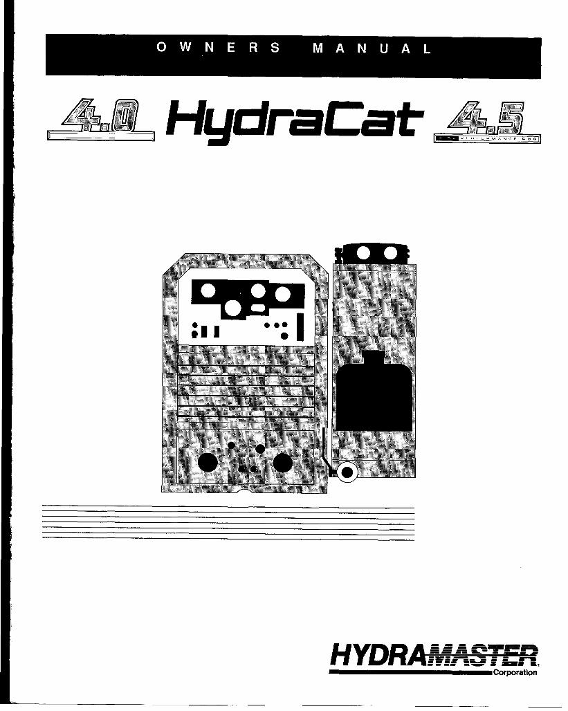
HudraCat
HYDl?A&#ASREZ.Corporation

I
1
I
I1319W HydraMaster Corp.Printed in U.S.A.

GENERAL INFORMATIONHowlhe System Works ..............................................................................2Spare Parts Recommendation ..................................................................2Machine S~cifi~tions .............................................................................2Warning and Caution .................................................................................2HowtoOrder ..............................................................................................3PatisOrders ..............................................................................................3One Final Note..........................................................................................3Purchaser’s Responsititi~ ........................................................................3Sales Representative’s Responsitili~ ......................................................3TwckSelection ..........................................................................................4TmckPre~ration ......................................................................................4Tmck Pre~ration illustration .....................................................................4Placementof Unitin Vehicle .......................................................................4Machine installation ...................................................................................4Propane Tank Location .............................................................................5Hard WaterArea Map ................................................................................5WaterSofiener ..........................................................................................5Wastewater Disposal AdviwW ..................................................................6Mactine A~ustments ................................................................................6
OPERATING INSTRUCTIONS & PRECAUTIONSshdup .. .. ..... .. ..... .. .. .. . .. ... .. .. .. ... .. .. ... .. .. .... ... ... .... .. ..... .. ..... .. ..... .. ..... .. ... .. .. ...6Shut Dom .................................................................................................6Cautions and Warnings .............................................................................7Freeze Protection ......................................................................................8Alternative Protection Using Anti.Freeeze .................................................8
Cleaning and Chemical Precautions ..........................................................8Cleaning Stroke Procedure/Over.wetiing .................................................8Water and Chemical Flow Operation .........................................................9Chemical System Maintenance .................................................................9Chemical Tank Trouble Shooting Guide ..................................................lQWater Flow Trouble Shooting Guide ........................................................ll
Vacuum System Information ...................................................................l2Vacuum Tank filter Bags.........................................................................l2Vacuum Blower Wanan~ ........................................................................l3
~,,..:VacuumBlower Lubri~tion .....................................................................l3Vacuum Blower Trouble Shooting Guide %--14............................................. ...
Heating System Information .....................................................................l4HeaterOperating lnstmctions ..................................................................15HeaterTroubleShmtingGuide...................................................................l5
CatPump Mode12900prating lnstwctions ............................................l6Cat Pump Wman~ .................................................................................l6Mode1290PartsList .................................................................................l7General Information for Cat Pump Repair................................................l8Servicing the Valve Aswmblies ...............................................................l8Servicing the Pumping Section ................................................................l9Servicing Sleeves and Seals ...................................................................l9Servicing Crankcase Section ..................................................................l9Cat Pump Trouble Shooting Guide ..........................................................2O
HydraCat Electrical System .....................................................................22
Onan Performer Engine SPCS . .. .. .. .. .. .. .... .. ... . .. .. .. .. .. .. .. .. .. .. .. .. .. .. .. .. .. .. ....23General Information about Onan .............................................................24
ENGINE MAINTENANCE ........................................................................25Oil System ...............................................................................................25
1
ignition ....................................................................................................27Cooling System .......................................................................................27Exhaust System .......................................................................................27Air Cleaner ...............................................................................................27Batie~ ........................................................................................... ..............28Periodic Maintenance Stiedule ................................................................29Engine Trouble Shooting . .. .. .. .. .. .... .. .. .. .. .. .. .. .. .. . ... .. .... .. ... . .. .. .. .. .... .. .... .... ..3o
Maintenance Procedures ........................................................................32Overall Care of Unit..................................................................................32
Maintenance Logs....................................................................................33
Warranty Information ...............................................................................36Warran~Pro~dure ................................................................................36Limited Warranty Plan........................................... ..........lnside back cover
LIST OF ILLUSTRATIONSPlywood lnstallation(ontwck &d) ..............................................................4AstiotudandRoof Vent...............................................................................4Machine XeDow Cleats ...........................................................................4~chine Configuration ...............................................................................5Pro~neTankPlumting .............................................................................5HardWakrMap .........................................................................................5WaterSofienerHook.up .............................................................................6pHChati .....................................................................................................8CleaningStroke Procedure ........................................................................8Chemiwl System Wring ............................................................................9WaterFlow .................................................................................................9Chemical Proportioning and Level Control ..................................................9WandValveAssembly ..............................................................................lOJetAswmbly ............................................................................................lOWandAswmbly .......................................................................................llWand Valve Stem Aswmbly ....................................................................llBy~ss Valve Aswmbly ...........................................................................llVacuum Flow............................................................................................l2Vacuum Tank RlterBags ..........................................................................l2BlowerLubPofi ......................................................................................l2Vacuum Blower Motor Lubrication ............................................................l3RlotBwnerAdjustment ............................................................................l5Model 290 Exploded Mew.......................................................................l7Pumping ~ction Cubway .......................................................................l8HydraCat Electrical Diagram ....................................................................22BasicUmensions. P224 ..........................................................................23Basic Dmensions. P220..........................................................................23OIMmsi~ ..............................................................................................25OlfilterLoMtion ......................................................................................26P220CmnkMWBreather ........................................................................26P224CmnkMWBreather ........................................................................26SewicingS~rkPlug ................................................................................27ArCleanerAswmbly ...............................................................................28SWcificGravi~Test .................................................................................28BatieqCaMeConnection .........................................................................28
LIST OF PHOTOSHydraCat (kontview.features labled) .......................................................7HydraCat(sidetiew. featureslahled) .......................................................7CatPumpMode1290 ................................................................................l6Semicingtie Pump...................................................................................l9Onan Performer Gasoline Engim .............................................................23Sparlr Plug Diagnosis ...............................................................................27
GENERAL UWWWIATIONT’hw manual contains installation and operation instructions as wII as in-formation rquired tar proper maintenance, adjustment and repair of thisunit. Since the first and mast important part of repair work is the correctdiagnosk of the trouble, a general troubleshooting section and componentmanual troubleshooting charts have fxen included for your convenience.
IMikea garden tractw, Iawmnower arcement mixer, all having one or twofunctions 10 fwrtarm, thebuck-mounted carpet cleaning plant has manyfunctions to pwform simultaneously.
* Engine has to run at a consistent RPM.‘ Vacuum has ta pull air and d@ water bad from cleaning site.● Waler pump provides stable pressure at proper water flow for cleaning.*Chemical has to be injected into the water stream at the
right cmcentration.* Heater must maintain proper hsat.* Vacuum tank must store dirty water until drained.
HOW THE SYSTEM WORKSThe water system takes incoming water at tap (low) pressure, combines itwilh chemicals from the chemical system and pumps it under pressurethrough theheatingsystern, anctouttothec]eaning tool. After being sprayedinto the carpet, Ihe water/chemicaf/soil solution is extracted by the vacuumsystem and returrwd to the waste recovery tank.
There is no guess wrk in the manufacture of these highly advancedcleaning pfmts.There must also be no guess work in preparing it to get thejob done in the field. h is the purpose of this manual to help you prqwtyunderstand, maintain and service your cleaning pfant. Follow the directionscarefully and you will be rewarded with years of profitable trouble-freeoperation.
It isimperatfvethat nw$eclfonbeoverlookedwhen preparing for operationof this equipment.
SPARE PARTSRECOMMENDATIONBecause your truck-mounted unit is capabfe of generating several hundreddollars Wr day, down-time on the unit can be very expensive.
In order to minimize such down-time, it is strongly recommended by themarwfacturcx that PU pumhase and keep in your truck the following sparepalls:
PART NO. 0ESC13fPTKIN WY.078-015 Flow meter kit 14178-(119 Wand vafve dunger kit 1Wlf4XJ4 Pressure bypassvafve kti 1076-005 Spray @ W06E 1048-029 Recovwv tank fitterbag 2078-001 cat 290 short cqp kd standard 1078-004 f%t 290 hoi CUPkit (~ tionat) 1048-023 Screen, qarden hose 6
0624W0 440 Mafequick conned 1052-051 440 Femete quick conned 1052-052 660 Male quick conned 1
a52-a53 660 F@mafequick mned 1
106-015 Ermine@plug 2010-021 HydraCalpump drive belt 1
MACHINE SPECIFICATIONS‘RAME: 2~ W, 59 L, 3& H. Steef with baked-on epoxy finish.
VEIGWE HydraCat 4.0:630 tbs. (dry ‘might)HydraCat 4.5:750 Ibs (dry weight)
;OWUNG: Steel with baked-on Epoxy finish.
NGINE: HydraCat 4.0: P22020 BHP OnanHydraCat 4.5:P22424 BHP Onan
GNfTfON: Electronic, Keystart.
ii-PRESSURE PUMP: Tri-Plex piston -- Cat 290- 3.5 W%!-1200 PSI -- @ 1200 RPM.
fACUUM BLOWER: HydraCat 4.0: 4MLHydraCat 4.5: 4LLSutorbuift W/l 2 HG Safety Relief.
:HEM[CAL SYSTEM: Electro-mechanical, meter Conlro!l@d.
WATER: Propane fired, thermostatically controlled (180,000 BTU).
NSTRUMENTS: 0-1000 High pressure gauge, Temperature gauge,/acuum gauge, Hour meter, Chemical flow meter, ignition key, Start and onndicator fights, Pump clutch switch, Circuit breakers.
?ECOVERY TANK: 70 gallon aluminum, Epoxy finish.
;LEANING WAND: Stahless steel with heat shield, Grip and replaceableracuum fips with stainless steel solution valve.
+f-PRESSURE HOSE I/& High-temperature linecflvin~ covered, Hoseated to 1250 PSI.
IACUUM HOSE: 2’ reinforced, 1 1/2’ reinforced.
STANDARD EQUIPMENT: Power conso!e, Sound suppression PackagqElectric Pump Clutch, Water heater, Vacuum Recovery tank, Carpetcleaning wand, Chemical jug, Chemicafjugholder, Chemkal@gfill line, (lperation manuaf, 150 ft. 2’ vacuum hose, 10 ft. 1 1/2” vacuum hose, 150 ft.Super-flex solution fine, 10 ft. drain line, 50 ft. water supply line, ~!d! Freeze guard system, Battery box withholder, Vandeca! package, Fuelsystem kit, Installation kit.
ADDITtONAL EQUIPMENT, HYDRACAT4.5: Oversize air handling pack-age, High-output component power pack, Super dual silencer system,electronic tachometer.
The manufacturer uses this symbol throughout We rnarwai to wwrrQfposslbie injury ardt?alh.
This symbol is used 10 warn of possible ei@gme?rMdamage.
2

HOW TO ORDER PARTSTo obtain a proper diagnosis of your malfunction, and to order warrantyreplacement parts, it is important that you proceed in the following mannec
1. Call HydraMaster Warranty/Service Department at (206) 775-7275.2. Give the Warranty/SeM”ce representative the following information:
A. Name of your company and your address.B. Equipment model (i.e. HydraCat, Bobcat 2, etc.).C. Date of purchase.D. Hours on the unit.E. Serial number of unit.F. Name of person authorized to order parts.G. Salesman unit purchased from.H. Description of malfunction.1.Pressure readings on high pressure gauge with wand turned
on and off.3. If warranty replacement parts are needed, please specify method ofshipment desired. NOTE: All replacement parts are sent freight collect, via:
A. U.P.S. D. Air ExpressB. Air Freight E. Auto FreightC. Air Mail
4. Do not give malfunctioning parts to a HydraMaster sales or servicerepresentative. All parts must be returned dlrectfy to HydraMaster,Freight prepaid.
PARTS ORDERSTo expedite your parts needs, please caii your saies representative.Inmost instance, he either stocks or has access to parts through a regionaiservice center. In the event parts are unavailable iocaliy, contact the factoryand coordinate your needs. if this becomes necessary, always indicate themethod of shipment you desire, i.e. UPS. Blue Label, Air Freight, AirExpress, etc.HydraMaster Parts Department. Phone (206) 775-7276.
ONE FINAL NOTEAnyquestionsyou have regarding the warranty program shouid be directedto the Warranty/Servkxr Department personnei at HydraMaster Corpora-tion.
We shall alwaysendeavorto be fairinourevaiuationof yourwarrantyclaim,and shali provide you with a complete analysis of our findings.
HydraMaster Warranty Poiicy (inside back cover)Effective February 1,1989HydraMaster warranty covers oniy defective materiais andlor workman-ship for the periods listed. Labor, and/or diagnostic reimbursement isspecifically excluded.
PURCHASER’S RESPONSIBILITYPRiOR TO ARRIVAL OF UNiT1. lnstali 5/8” extenorplywoodflooring in vehicle and cover with artificial turf.2. Have beiiy mounted propane tank installed on vehicie. Tank must be
propane vapor type.
3. Purchase heavy duty 42-60 amp hour battery and have battery ‘slow’chargedjfnew. Ifbatteryisnotfully chargeddamage can occurto tie enginecharging regulator.
READiNG OF OWNERS MANUAL: it is the purchaser’s responsibility toread the unit operation manuai and to familiarize himself with the informa-fioncontainedtherein. Speciai attention shouidbepaidtoaii Cautionsand WARNINGS.
SALES REPRESENTATIVE’SRESPONSIBILITYACCEPTANCE OF SHiPMENT:1. if unit showsanyoutward signsof damage, do not sign thedeiiveryreceiptuntii you have closely inspected the unit and noted any damage on thedeiiveryreceipt. Have the freightcompanyrepresentativeacknowledgethedamage by signing the notation of damage on the delivery receipt.
2. The salesman from whom you purchased your unit is responsible forsupervising the comect installation of the unit in your vehicle and thoroughlytraining you in its operation, maintenance and precautions.
CORRECT iNSTALLATION iNCLUOES: Installation of through-floor fit-tings for propane and gasoline fuel lines; installing propane regulatorincluded with unit, outside vehicie; placing unit and recovery tank in vehicleand securing them with bolts or tie down cleats ;connecting all propane andgasoline Iinew connecting battery; checking pump, vacuum biower andengine oil ieveis, prior to starting unit; starting unit to check engine to seethat ail systems function normaily; aiw checking ail hoses, wands, etc., forcarect operatiin.
TRAfNiNG SHALL iNCLUDE: Thorough review of the operation manualwith purchase~ instruction and familiarization in: how to correctiy start upand shut down unit; howtocorrectiyciean with the unit; how, where and howoften to check and change component oil ievels; how the unit’s systemsworlc how to troubleshoot the unib how to do basic repairs; safety precau-tions and their importance; freezing damage and how to avoid it and athorough review ~ the unit warran~ and w&ranty procedures.
HOURS TELEPHONE NUMBERSMonday -- Friday (206) 775-7272 Generai offices
8:00 am To 5:00 pm (206) 775-7276 Parts Department
PACIFICSTANDARDTIME (206) 775-7275 Service/Warranty(206) 771-7156 FAX
3

TRUCK SELECTIONThe preferable vtllclefor HydraCat iristallationis apam?l van with a heavy-duty swyx?nsirm package. The capacity of Iho van should be a heavy-duty1/2 ton at ttm minimum and more preferably a 3/4 ton o&pacity.
TRUCK PREPARATIONThe manufacmrarmmmmands theinslallation ofpl~od flooring coveredwiftr paly propylene backed astroturf (do not use rubber-backed) in thevehicl~ prior to installation of machine. This provides a metal to cushionmounting rather than metal to metal, provides insulation and makes anattractive van interior. Aslroturf should be color keyed to van interior.
Materials Needed:1.2 sheets 4x8x5/fY exterior plywood2. &xl 2’ piwe of commercial astrotwf3. 16-f lM sheet metal screws4.1 quart marine adhesive (optional)5.1 staple hammar wII12” staples(See illustration for correct placement of plywood flooring)
TRUCK PREPARATIONILLUSTRATIONFIRST, covtwth~ truck kd with 5/8’ p@vood using metal screws to secureit as shown.
Plywood Immlwcm5/8” Plywood
SECOND, wlecttWappro@ate coloras!roturfto match yourvan andcmtie plywood and staple in place. A standard van requires a piece 6 feet b]12 feet.
THIRD, Hydrafdasler strongly recommends an aluminum roof vent be instalIed over Ihe location selected for mounting the machine. HydraMastealsohighly recommends a flue be installed between the lop of the heateand the roof vent. Thiswillallow hot air from the heater to escape.
ILACEMENT OF UNIT4 VEHICLEwe are two recommended unit placements:SIDE DOOR: Most installations are side door. This provides rearamsspaccessories and hoses as well as unobstructed access to compmwnti]rfdng side of machirw, thus making it a bit easiw’ io perform maintenanceIWor repair without removing unit from the truck.
REAR DOOf%Afthaugh this location partly limits working access, itdoeswet the noise away from the cleaning site. Some cleaners in the coldereas prefer this location because if puts the weight mass ow?r the rear~eels for better traction in ice and snow. Rear mounting requires ttw unitbe slid to the right side as far as possible. This not only provides adequatexking space on the component side of the unit but also makes bettersight distribution inside the van (engine and cornponer?tweight line up~erdrive shaft). Also, it is physically easier to load unit into rear door dueheight of van bed.
rrsure that machine is well secured to the floor of van with hwchvafe~pplied.Sudden orwash stop Wlcause machine to rocket foru%wd,all 750s. wrth! Protect yourself and the machimz SECURE lT#
Machine Tie f?own CleatsI
UIACHINE INSTALLATION‘here are two ways of positioning the machine in the truck as shown. Thwure also two locations for the vacuum recovw’y tank to be pasitiom?d. l%%w?standard way with fhe tank directly alongside the machine. %?cond,withIe tank across the back of the machine as shown on the illustration on theIext page; this location is most spaca eflicient. Whichew?r way YOUsdect,lake sure the tank and machirm are secured to the tloorof the van to insureIriver safety.
t is important that the machine lx? placed as close to the door as possibh?o that outside air can b pulled into the engine for proper cooling.
4

I
I
t
$
Machine Configuration
E::———0 .UrloidB----:
Ii isrecommendedbyfhe manufacturerthatthe exhaustfi’om the frontofthmachine be venfeddown under the truck to prevent carbon monoxide frofentering ihspb We. Aiwayspark the fruckso the exhaustis bfowiqaway torn Ihejob site.
Themanufactureraiso recommends that instillation of aluminum vents ithe truck roof to a//ow heat from the heater to escape.
Never operate this machine with a portable propane tank oraportable gacan inside the truck, doing so increases the risk of a fire or explosion.
Mount afire extinguisherjusf inside the rear or side door foremergencie:
PROPANE TANK LOCATIONEither the 10 gallon or 16.5 gallon propane tank will fit this location. Havyou local propane dealer install the tank you select and purchase. Thmachine will come with the proper propane regulator. fTank must havvaporoutiet.)
Professions/insta//ation offudsystems is strongly recommended. Aiwqensure compliance with stite andlocdregulations pertaining to fueiinstaIations.
HARD WATER AREA MAPThe quality of water variis greatly throughout the United States andinfluences the reiiibility and effiiienoy of equipment in direct proportion toits !evel of hardness. The map below detinesareas which cornprumise fluidrelated components such as hoses, fittings, heaters, pumps, valves andwater cooled engines.
Cleaning efficiency and equipment life is increased, chemical use de-creased and the appearance of cleaned carpets enhanced when watersofteners are incorporated in hard water areas. Manufacturer stronglyurges the use of water softener units in areas exceeding 3 1/2 grains peroallon. Using the legend as a reference, determine the quality of water in~our area aid take ;ction immediately should it be nece&a~.
IWater Hardness
Grains ..
Per Galbn
n ‘-3iQ = 7-101/2
Izzzz 31/2-7 _ 101/2 and above
WATER SOFTENERMany areas of the country have an excess of minerals in the water whichresults in what is commonly called “hard water”. These minerals tend toadhere to the insides of heater coils andotherpartsof the machines causingdamage and a loss of cleaning effectiveness.
Reports from several of our machine users commending the results of theuse of water softeners inconjunctionwith their machines prompts us to rec-ommend the procedure to everyone in a “hard water” area.
The relatively low cost of a water softener service is more than made up forin the increased Iifeof machine parts andcontinuedcleaning efficiency. Thewater softener will also increase fhe effectiveness of the cleaning chemicalbeing used, therefore, less chemical will be needed.
Contactawatersoftener distributor in your area forinformationon the rentalof a simple water treatment unit to carry in your truck. Be sure to change thewater softener in accordance with the capability of the softener. Example:If the softener will treat 900 gallons of water and machines uses an averageof 30 gallons perhourof use, andanaverageof 5 hours a day, wouidbe 150gallons a day. 5 days would equal 750 gallons of water, therefore, thesoftener would be changed every 6 working days for maximum softening.
(s6eil@laum,wpi?#e)
5

I
— C#h-morning VVatar
From Faucet
Garden I-fose
Water Softener
WASTEWATER DISPOSALADVISORYThem are laws inmost communities prohibiting the dumping of recovers‘gray” water from carpet cleaning in any place but a sanitary treatmelsystem.
This cleaning rinse water, reccwred into your unit%vacuum tank, contairmaterials such as dete~ents, which must be procwed before being sefor streams, rivers and reservoirs.
IN ACCCMM2AMCE WITtf THE EPA, STATE AND LOCAL MWS, DMM MWW$f OF WASTEWATER MK7 GUTTERS, ST0f?h4 DRAINSTllEAA@ RESEJ?Vt’WS, ETC.
Inmost cases, anacoep!ab[e method of wastewaterdisposal is to discharfinto a municipal sewage treatment syst@m after first filtering out solmaterial suctwmrrpetfiber. Access to the sanifwy system can be obtaimthrough a toilet, laundry drain, carwash drain, RV dump, etc. Permissi[should first be obtained from any concerned party or agency.
One dis~sal rmtfwd which usually complies with the law is to accumulathe wastewater and haul it to an appropriate dump site. Another solutionthe disposal pmblam is !0 equip yourself with an Automatic Pump-OSystem. Thetm systems afie designed 10 remove wastewater from tltixtractor’s rwoovery system and actively pump the water through hosesa suitable disposal drain. Properfydesignecf, they will continuously moniitie Iml of wasttwvaler and pump it out simultaneously to the cleaniloperalion. Tim hidden benefit of this procm is thatthe operator doeshave to stop his cleaning to empty the recovery tank. HydraMaster makan A.P.O. System available which can be ordered with new equipmentinstalled Iat@r.
Thi?penalties for nwr+ompliance can be serious. Always check local la’and n?gufaticms M be sum you are in compliance.
MACHINE AthKISTMENTSAlthough MS unit has been factory adjusted, it may require additioladjustmentsto achieve optimum performance; i.e. altitude may require uadjustment and ambient temperatures may require heat control adjument. When required, cansult an authorized ~epresentative.
START UP1. Perform daily/periodic mainttrnance as specifbd by the owrws manual.2. Connect all required hws.
, 3. Connect c!eaning tool to length of hose required to perform clwaning.
L Mix tankmust&M/priorto @rithmr.
. Start engine (choke as required}. Engine is at operating speed (r@cammended -2600 RPM). Allow warm-uP period of 2-5 minutes.
I 6. Spray wand to void al air from system: When the mix tank tmgins a fillcycle, the chemical flow meter may be adjusted to your desired setting.
NOTE: Recommended carpet cleaning pressure is 300 PSI.
7. Once all air is voided frum system, heatw may be ignited.NOTE: If not familiar with operation of this healer, refer to heater section of
the manual.A. Open propane valve on the tank.B. Ignite pilot on the heater.C. To ignite burner, turn dial to “on” position.
NOTE: If you suspect that the unit has been frozen -DO NOT light theheater. Thaw the heater and check for leaks.
8. Turn on burner, adjust dial to normal or slightly below for 200W.9. Commence cleaning operation.NOTE: Chemical flow meter set at 5 GPH is a 1 to 30 mix ratio and 10 GPH
is 1 to 15 ratio.
NOTE: Hot cfbnate opw’ation [above 90°F].When operating this unit in a hot climate, HydraMaster highly recommendssome additional precautions.1. Operate with side and rear doors fully open.2. Vent heater through the top of van.3. If vapor lock conditions arise, machine cover may need to be raised to
allow additional heat to escape from canpwtmt?nt.
NOTE: Cold cfimate operation (below O°F).When operating this unit in a cold weather application, HydraMaster highlyrecommends some additional precautions.1. If nossible carrv Your own fresh water SUDDI%2. Hookup to ho~wkder source if possible to’keep your incoming garden
hose ~m freezing.3. Do not close van doors in front of machine.4. Be aware that solution lines laying on frozm ground may frewe.5. Contact local propane dealer about cold weather propane use.
SHUT DOWN1.Turn heater to ‘off” position. Spray wand for at least 3 minutes to allowthe heater coils to cool.2. Close valve on propane tank and through floor hookup.3. Remove vacuum hose.4. Flush clear water through chemical system for 10 seconds. (Vinegar
should be rinsed through system weekly.] Turnoff chemical flow meter.5. Tumon cleaning tool to flush chemical from unit hoses and cleaning tool.NOTE If freeze guard is necessary, perform steps 1 & 2 of freeze guard
procedure at tlls time.6. At this time, the blower should be lubricated with [email protected]. Shut engine down.8. Drain vacuum tank. Vacuum filter should @cleaned prior 10mobilization
of van. NOTE If freeze guard is necessary, pwtorm st~ps 3-7 of fr@ez@guard procedure at this time.
6

VacuumHour Gauge CircuitMeter, I Breakers
/Pressure
Gauge, \ I1’,J:ue/va:%TankTemp.
I
\\l l/~Gauge ,,
Choke “
Vacuum Pump ;JLubrication Port &;
)~’
I
High Pressure ~]Pump Switch ‘~l
#!!‘/$;#
Machine _Exhaust
/ ‘Machine‘vacuum‘ankIncoming
/1Exhaust Dump Valve
WaterBv~ass
Hiah Pressure’ Valve
Cle%ing Solution
ChemicalHigh Pressure Water Pump
. . — Water PumD Clutch
Engin6/’
Heater Control Coupler
\
‘Freeze GuardValve Fitting
Vacuum Mix TankHydra-Heater Pump Drain Valve
ENGINE COOLING
Units employingaircooledengines mustnotln? enclosed withina van withdoors and ~ndows closed. Excessive temperatures within the engine willresultinpremature engine failure anda compromise ofappiicable warranty.
LEVEL OPERATION
During operation, van or tiailer must be parked on /eve/ ground not toexcwed + or -1P. Failure to insure proper leveling may prevent properinternal lubrication of engine, vacuum anoYorhigh pressure components.
FREEZE PROTECTION
Mother nature oives little wamin~ as to her cold s@ls. Therefore, wtect-irrg this equifient from fi’eezing will save cosfly down-time. Placing anelectric heater in the Puck or parking the truck indoors, will help to insureagainst fleezing.
LIGHTING HEATER
Neverputyourface down close to the opening of the heater when lighting.
STRONG PROPANE ODOR
Never light the heater if you smell a strong odor of propane around theheater.
HOT SURFACES
During the operation of this equipment many surfaces on the machine wilibecome vetyhot. When near the van foranyreason care mustbe taken notto touch any hot sudace, such as heater, engine, exhaust, etc.
NO SMOKING
ftis unsafe to smoke in or around the vehicle.
7
MOVING PARTS
Never touch any pad of tie machine that is in motion, severe bodily injurymay result.
CARBON MONOXIDE
This unit generates toxic fumes. Position the vehic/e so that the fumes willbe directed AWAYfrom the job site.
DO NOT PARK where exhaust fumes can enter a bui/dif?g through opendoors or windows, air conditioning units or kitchen fans.

FREEZE PROTECTIONAny frw~zing of this machine is not covefied by warranty and during the~ldelrmantisofo~mtion, careful protection should be of utmost concern.
THE FQLLWW4G PRECAUTIONS ARE RECOMMENDED:1. Run machine befcm leaving for the first job to insure nothing has frozen
ha night lmfore, including hoses and wand.2. Insulak the gafidt?nhose from the cold ground by running it through an
extra 1 1/2 inch vacuum hose.3. In colder dirnates, insulating the truck walls and floorboards will help
prutoct the unit.4, Don’t procrastinate during thec!eaning operation or the hot water solution
line will alw freeze an the ground. The solution iine should be insulatedin exlrerrmly cold climates.
!$.Whenever ~ssible, the truck and machine should be stored in a heatedgarage at night or over the weekend. If not possible, place a 1500 wattelectric heater inside the truck, aimed directly at the machine. Never usea propane heater-it causes excessive moisture on the truck ceiling andthe possibility of it going out is higher. If the machine and truck are leftoutside with a heater, you should first drain of possible water from themachine cleaning tools and hoses. (They freeze also.)
TO DRAIN THE MACHINE FOLLOW THESE STEPS1. Siphon a 50150 mixture of anti-freeze and water through the chemical
ftow meter.2. Drain the mix tank.3. Connect Ma freeze guardhow? to the rwxwery tank.4. Connect Ihecdher ond of the freeze guard fitting to the freeze guard fitting
Iocatfid on the sido of the machine.5. Connect an open 440 quick connect to the fittings marked “cleaning
solution” on the front oithe machine. (An alternative would be to connectyour solution hww and wand, w as to freeze guard them also. If youchoose to do thisycw will also need to hold the !riggerdown on the wand.)
6. Start the unit, allowing the vacuum from the machine to drain the lines.7.* Remove tfre garden hose inlet adapter from the end of the garden hose.
Conrmct the adapter to the incoming water quick connect on the front of9hemachine.
8.’ Place a vacuum hose over the garden hose quick connect and allow thevacuum from the machine to drain the lines.
* i4n alternative to #7 & 8 would be lo make an adapter to allow you to us@the premade freeze guard hose.
NQTE: Prior to freezo guarding your rnachinemake sure the heating systemhas been cooled down.
ALTERNATE PROTECTION USINGANTI-FREEZE:1. Follow We draining procedure.2. Cmnect solution hoses and wand tomachine.3. Pour a 50/50 ariti-$reeze sokJtion into mix tank.4. Turn on machine and engage clutch. Spray the wand.5. Continue to add anti-freeze solution until mixture comes out of wand set.6. Remove and store hoses.
If you are using an anti-freeze solution to protect your machine fromfreezing. 1[is ne~ssary to flush the machine in preparation for use. Simplyconnect the unit to fresh water and spray the wand until anti-freeze solutionis discharged. The anti-freeze soiution maybe recovered by spraying intoan empty container. This solution can be used several times.
BE SURE IT’S PROTECTED! Freezing will cause GRIEF, MONEY andDOWF&TIME. Don’t mess with Mother Nature!
CLEANING AND CHEMICALPRECAUTIONSYourmobile carpet cleaning plant has been engineered using the !at@standnest sophisticated technology available, to produce the finest carp@t~eaning results possible. Despite this, however, it remains onlya tool of thexpet cleaning trade, and it can produce only as good a job as Me person]Perating it.
There are not short cuts to good ca~t cleaning. It requirws time, cleaningmowledge and the use of good chemicals.
The manufacturer recommends the use of spotting agents, and traffic lanenleaners prior to the actual cleaning of carpeting, as required.
The use of some chemicals through your mobile carpet cleaning plant canseriously damage the internal plumbing, high pressure pump and heater.(Chemical such as concentrated acids, solvents, and some paint oil andgrease removers w/high cwwentration of solvents.)
The manufacturer recommends only the use of chemicals containing rustand corrosion inhibitors and water softening agents to prevent chemicalbuild-up which may lead to component failure and warranty invalidation.
NOTE: At no time should a chemical solution with a pH of less than 7 orhigher than 10 be used in the unit.
I pH CHART I1234567891O 1?12 13 14) I 1 I I I I I I I I I I
+AOD - *NEUTRAL ‘ALKALINE~
CLEANING STROKEPROCEDUREIOVER-WEUINGPIJRPOSE:TOeliminate excess moisture rernainirrg in the carpet fiber andthe sawtooth appearanw? which results from diagonal movement of thecleaning tool on all types of carpet.
PROCEDURE: Always move the cleaning tool in smooth foward anciMck-ward strokes. Apply slight pressureto the forward stroke while the solutionis injected into the carpet. When extracting (drying), apply firm pressure onthe foiward stroke to ensure a positive “lock” for the vacuum and minimizethe “hopping” effect resulting on unsmooth carpet. During the forward andreverse strokes, movement to the right or left should only be a~omplishexiat the extreme rear of the stroke. Overlapping is also important to ensureeven application of solution to prevent saturation when cleaning wand isstopped twice at the same point at tie rear of the cleaning stroke.
Failure to adoot this mocedure can result in increased chance of “cleanstreaks”, fiber’shrinkage, brown out, and longer drying pdods.
INCORRECT METHOD CORRECT MEWMN2
Overla~ Between Strokes
pfl~q-!,ir!‘<!,.Cbanmg CleaningStroke Stroke
8

OVm”wmmlciOver-wetting is annoying to all concerned and sometimes leaves a bad im-pression of the cleaning process used.
THESE ARE SEVERAL AREAS THAT WILL CAUSE OVER”WEITING:1. Too Iew vacuum strokes or improper sawtooth vacuum strokes as
shown in the previous illustration.2. Obstructed, kinked or cut hoses.3. Vacuum tank drain valve left partially open.4. Clogged vacuum blower filter or vacuum tank lid not sealing propxly.5. Cleaning a heavily foam-saturated carpet without defoamer. (We recom-
mend crystal type.)
WATER AND CHEMICAL FLOWOPERATIONThis electro-mechanical system has been designed to be simple andtrouble free. Incoming water flows first through the Solenoid Control Valve(1) and the low pressure Chemical Injector (2) which are both mounted onthe exterior of the mix tank. As the water passes through the ChemicalInjector, it is automatically proportioned with a predetermined quantity ofdetergent. The MixTank(3)isequippedwith two different float switches, theWater Level Float (4) responds to the level in the tank and will maintain theproper volume of solution to be reserved for the water pump. The secon-dary, Low Water Float switch(5) isasafetyswitch that isdesignedto protectyour system from sudden or unexpected loss of water supply. If, forexample, the water source at the house were turned off, the water level ofthe mix tank would drop, activating the secondary switch, which automati-callydisengages the system and pn?vents the water pump from running dry.
The desired chemical injection ratio may be obtained by an adjustment ofthe Chemical Flow Meter (6) during the fill cycle of the mix tank. Water mustbe flowing into the mixtankinorderto adjustthechemical mix. The chemicalwill flow from the Chemical Jug (7) to the Chemical Flow Meter, then to theChemical Injector where it is proportioned into the Mix Tank at the desiredchemical setting.
NOTE: %Mththisuniquechemical system, thechemicalflow is proportionedonly during the filling cycles of the MIXTank, not during the direct sprayingof the wand. Therefore, it is possible that as your wand is spraying, you mayhave no chemical flow. Also, the converse is true in that you may not bespraying your wand, but if the mix tank is in a filling cycle, your ChemicalFlow Meter may be active at the desired flow rate.
The chemical proportioning system will mix chemical with water at a 1to 30ratio when the Flow Meter is set at 5 GPH, or a 1 to 15 ratio when the FlowMeter is set at 10 GPH.
At this point in the flow, solution (water with chemical) will now be siphonedfrom the bottom of the Mix Tank to the inlet of the Water Pump (8). Whenthe wand is not using solution by spraying, the solution will be bypassedfrom the bottom of the brass Pressure Relief Valve(9), back to the Mix Tank.
When the wand is spraying, the solution continues its flow to the WaterHeater (10). The coils of this heater have a capacity of up to 2 gallons,therefore it is extremely important that all air pockets are bled out of theheater prior to initial start-up. This maybe achieved by running the watersystem, without the heater on, for approximately 80 seconds.
CHEMICAL SYSTEM MAINTENANCEThe chemical lines may need to be flushed with vinegar periodically toprevent abnormal chemical build-up. This flushing may be done by remov-ing the clear plastic hose from the Chemical Jug and inserting it into a one
uart container of vinegar. This should be done with the Chemical Flow!eter setting on 10 GPH and the Water Heater “off’. Simply spray waterom the wa~d until the quart of vinegar is exhausted, the repeat the @wessith one quart of clear water to void all lines of vinegar.
Chemical System WiringSolenoid Valve
Relay ,.~Float E ,.~
SwitchGND
X!/’ To Ignition Switch88 ~. 85
h.
G~D ‘--l‘..
Water Flow
11 - Pressure Guage6- Chemical Flow Meter 12- Incoming Water7- Chemical Jug 13- Tank Drain8- High Pressure Pump 14- To Wand+ High Pressure + Low Pressure
Chemical Proportion and Level Contra\M,, Tank
6FA-6UFS I$
=eCk=
fl
-0
~u
B . ‘“’W’”’ B””’Swng
o SIs Ball
& Check valve ;
*:5$3’’HeFj~jii$
g;zj_:Dlen;nq~,-,4, va,vech,y
Mo.n!tng+wJw ,3)
(la ‘ WaterIdet
—-, .— -—.
+-=” –d12 Voc Mo.ntlng
cm Plato
9
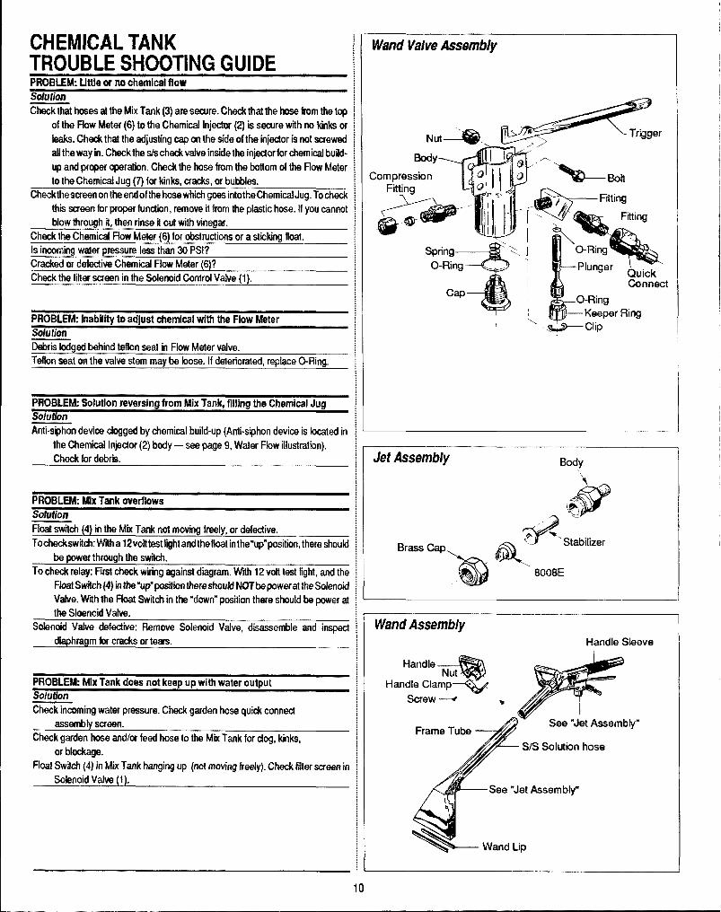
CHEMICAL TANKTROUBLE SHOOTING GUIDEPRQHLEW. Uttla or no chemical flow%hldon
Chackthtat hoses af the Mix Tank(3) are secure. Check that the hose from the topof tkw Flow MrXar (6) to the Chemical lnject~ (2) is seam with no kinks orleaks, (M& thal the ad~ustingcap on tho side of the injector is INI! screwedaf!ttw way in. Clmcklhe $/s check vafveirw.idethe injedorforchemical build-
up and pqer qwration. Chec& the hose from the botiom of the Ffow Meterto the Ctmrnicaf Jug (7) for kinks, cracks, or bubbles.
Cf’mckthwxraen ontheemdof the hose which gces intotheChemicaf Jug. Tochackthii scram for proper function, remove it kom Itw plastic hose. If you csnnotblow Ihrough if, tti rinse if out with vinegar.
Check the Chemical flow Meter (6) for obstructions or a sticking float.Is incoming waler pressura less than 30 PSI?Cracked w cle!ective Chemical Flow Meter (6)?Check the fitter wren in the Solenoid Control Valve(1).
PROBLEM frmbillty to adjust chemical with the Flow MeterSahtionDebrii Iodued &hind Mlon %at in Flow Meter valve.Tdhm seat on the valve stem maybe hose. If deteriorated, replace O-Ring.
PHCWLEM: Solution rmmrsbrg from Mix Tank, ffllhrg the Chemical JugSohlfk?nAnti-siphon dwice cfogged by chemical build-up (Anti-siphon device is bcated in
the Chemical Injedor (2) body — see page 9, Water F!aw illustrakon).Check for debrii.
PRQBLEM FAx Tank overflowsmlution
Float awitc+r(4) in the Mix Tank nd moving ireely, or d~fadive.
TochmckswitctrWNma 12voht@[ghiandtheilut inthe”up”position, there should
b power through the swhh.To check relay: First check wiring against dmgram. W* 12 volt lest fight, and the
FloafSw%ch(4} inIfre”up”posilierr there sf?cmklNOT@owerat !heSolenoidVahw. Wth !he Float Switch in the “down”position there should be power afthe SIoarwid Vafve.
EKderroidValve defectiwx Remove Solenoid Vafve, disassemble and inspect
diaphragm Iw cracks w tears.
PRQ5LE~ Mix Tank does not keep up with water outputSOlufhltl
Check incoming water pressure. Check gaden hoaa quick connedassembfy screen.
Check garden hose ardor feed hose 10 the Mix Tank for dog, kinks,
or blockage.Float Swifd (4) in Mix Tank hanging up (rmf moving freely). Check fifter scmn in
Solenoid Vafve (1).
Wand Valve Asswnbfy
Ekldy
-TII I *C
CompressionI
QI *=*I6
Fitting
~?*
--~;~’ :11“?’<F~@\Spring
3’L%
.\ O-Ring
O-Ring i Plunger Quick
Connectcap
[Cl-Ring
Keeper Ring\
Jet Assembly Ekdy
Wand Assembly
Ha
‘b”
I
I
I
II
~
I
10

I Wand Valve Stem Assembly
I@ +— Retainer
Keeper Ring ———+~
(
Plunger —
O-Ring
uI
@— O-Ring
I
Bypass Valve Assembly
BYPASS PARTS LISTREF. NO. PART NO. DESCRIPTfON QTY.
3 OOO-105-1OI Thrust plate, Bypassvatve 14 OOO-105-1O2 Piilon plate, Bypassvalve 15 OOO-O78-1O1 Kt, seal for Bypass vafve 17 000-14B-oo4 Seat & C43ing, Bypass vafve 18 000-097-005 O-Ring, Bypass valve fitting 1
WATER FLOW TROUBLE SHOOTING GUIDEPRoBLEkk LOSSof pressureCslrse solution=ve or blocked check vafves in high pressure pump cyfinder head. Disassemble cylinder head and replace or cfean applicabfa check valve.Delaminated, Idnked or dogged hose between the mix lank and fhe high Remove and replace defective hose.
pressure pump,Defective pressure refief valve or debris in pressure relief valve. NOTE lle high Disassemble and clean pressure relief valve as illustrated in drawing above.
pressure bypass vafve is desgned to fully dose when the cleaning teal isturned on. Any foregn matter colleding on the piston will prevent iull closure Replace defective or worn out bypass cup.of fhe valve id allow a portion of the water to continue to circulate instead ofbeing routed to the ciaaning tool. To correct this situation, the bypass vafve Replace bypass valve.must be disassembled and dearrad (refer to illustration provided abve forbypass disassembly).
Oelective or worn cups. Remove and replace piston cups as defined by pump manuat.Loose driie belt Ior high pressure pump. Readjust belt as required or replaos if defective.Pump inlet Ystrainer dogged Check lank for water. Clean strainer. Clutch disengaged?
PROBLEM: Excessive water flowcause SolutionWorn out spray jet. NOTE: Cleaning tools designed to spray a constant fbw of Remove and replace spray jet.
1112GPM will average 1 gafbn of flow per minute in adual working situationssince lbwis not continuous.An average flow of 1 GPM results in 6000gallonsof fbwforevery 100hoursof unito~ration. Spray tips arecapableof fbwratesfor approximately 20,000 gallons. They should beraplacedtherefore, approxi-mately every 350 hours, Worn spray jets allow a greater average rate of flowthus reducing desired temperature fevels.
Reduction of flow. Due to increased length of sloution hose. NOTE For every 50feat of hose, bevond,100faet intotdlength,ame~urtile losoffbwisexpenencd. Ttisconditionis a result of the increased fridion experienced by the water as it passes
through the hose. Therelore, if is necessary to increase the pressure at themachine 40 PSI for every additional 50 feet of cleaning solution hose over100 feat.
11

—VACUUM SYSTEM INFORMATIONThe vacuum blcwwr incmporated in this machine is a positive displacementIokwtype, manufactured by Cooper Industries. The performance and fife oithis unit is gfieatiy dependent on the care and proper maintenance it reCeiv@$.
Becauw?of the CIOWtcdmum.es between the lobes and housing of the vacuum blower, did objects entwing the inlet will damage the internal lobes,g~ars and bearing or direct drhm coupler.
To p~event this, a stainless steel filter screen has been placed at the vacuurn inlet inside the vacuum recovery tank. This stainless steel screen isfinger tight and should be removed for cleaning weekly.
When machine is Ming run fir iesi purposes and the vacuum inlef on fo~of machine is open, caution should h? used.
To protect Ih@vacuum blower from overloading and damaging itself, thertis a vacuum rdi~f sys!em installed on the vac tank. When the vacuum tan}inlet is completely sealed off, a maximum of 14 HG will be attained. A hokon the top blower pipe eltmw acts as the lubrication point. At the end of eactday, LPS 1 or Pennzguard should be sprayed in before shutting down th[machine. See blower lubrication W4ration. If you fail 10 Iubricaie tfwvacuum blower daily, rust doposils and moisture will decrea~ the life of ttwvacuum Mower.
Read the vacuum blower rnanualcarefully forpmperoil change and greawapplication. The maintmarm log may differ slightly from the manual, buthe truck-mounted carpet cleaning machine application is very demandiryof the vacuum blowerandtherefore it should be maintained more regularly
NOTE: Vacuum tank isprotecfedfrom ow?rflowirrg bya vacuum tank, fleakill swi[ch. This swiich is not acfiwated by foam, only byliquid.
vacuum Flow
S/S Filter Recovery Tank\
Filter Bag/
MXIUM TANK FILTER BAGS/drafdasler filter bags are designed to trap all of the lint, sand and dirltha!wld normally collect at the bottom of your vacuum tank. The w? of theselgs, if emptiid at the end of each job; will eliminate the build-up cdmuchthedebt%in the tank. Th@drawstring top of these bags is ckmigrwd to bed to the incoming dirty water inlet in the vacuum tank.
Jreorder bags use part number 049-029.
Vacuum Tank Filf@r Bags.Vacuum Tank MM
\:7Blower LubePort
I
\/
LSpray lubricant into bloww’ lube port for 3 to 5 seconds,then immediately shut off machine. Use only LPS 1 or
Pennzguard moisture displacing lubricants.
12

VACUUM BLOWER WARRANTYFULLER warrants products of its manufacture to be free from defects in malerial and workmanship if properly installed, maintained, arid operatedunder normal conditions with competent supervision.
No person, agent, representative or dealer is authorized to give any warranties on behalf of FULLER nor to assume for FULLER any other liabilityin connection with any of FULLER’S products.
This warranty shall extend for two (2) years from date of installation provided this equipment has been put into servicw within six months aftershipment from tie FULLER factory. If repairs or replacements are made by the Purchaser without FULLER’S prior Mitten consent, FULLER’Swarranfyshall cease to be in effect. No allowance will be granted for any repairs or alterations made by the Purchaser without FULLER’s prior writtenconsent.
Machinery, equipment and accessories furnished by FULLER, but manufactured by others, are warranted only to the extent of the originalmanufacturer’s warranty to FULLER.
FULLER agrees at its option to repair at the point of shipment or to replace without charge f.o.b. point of shipment, any part or parts of productsof FULLER’S manufacture, which within the specified warranty period shall be proved to FULLER’S satisfaction to have been defective whenshipped, provided the Purchaser promptly notifies FULLER, in writing, of such alleged defect.
FULLER’S liability to Purchaser, whether in contract or in tort arising out of warranties, representations, instructions, or defects from any causeshall be limited to repairing or replacing of the defective part or parts as aforesaid, f.o.b. point of shipment.
No liability whatsoever shall attach to FULLER until said products have been paid for. EXCEPT AS STATED IN THIS SECTION AND IN THEPRECEDING SECTION TITLED ‘WARRANTY’ AND EXCEPT AS TO TITLE, THERE ARE NO GUARANTEED OR WARRANTIES OFMERCHANTABILITY, FITNESS, PERFORMANCE OR OTHERWISE, EXPRESS, IMPLIED OR STATUTORY, AND FULLER SHALL HAVE NOLIABILITY FOR CONSEQUENTIAL, INCIDENTAL OR OTHER DAMAGES, HOWSOEVER CAUSED.
DATE INSTALLED MODEL SERIAL #
FULLER COMPANY 2966 East victoria Street Compton, California 90224
VACUUM BLOWER LUBRICATIONAt the gear end the timing gear teeth are lubricated by being partiallysubmerged. The gear teeth serve as oil slingers for gear end bearings. Atthe drive end of the bearings are grease lubricated.
FILLING PROCEDURERemove square head vented oil fill plug (A) on gear end. Remove oil levelplug (B) located in the head plate. Fill gear case until oil drips out of the oillevel hole (B). Use lubricants as listed. Add fresh oil as required to maintainproper level. The oil should be drained, flushed and replaced every 1500hours or more frequently if inspection so indicates. The oil drain plug isat(C).
NOTE: Older units may have the oil fill level and drain holes located in thecast iron gear case instead of in the head plate. Bearings on drive end ofblower require grease lubrication every 100 hours of operation. Bearingswhich require grease lubrication will have a grease fitting (D) at eachbearing. When regressing, the old grease will be forced out of the ventsduring operation. To prevent damage to seals, these vents must be keptopen at all times.
.
Vacuum Blower Motor Lubrication
1
13

VACIKJM BLOWER TROUBLE SHOOTING GUIDEPIW5LEM Loss cd prw$si.irnCarkm Solution
Collapsed vacuum hose between blowm and vacuum kink. Remove and replam hose. NOTil A .speckd r@irrfcmd hose is requirwdfor replacement.
Chfjgad skddese steel Ikmr, Remove and dean or replaca stainless steel filter.
IMwAive vacuum lank seat. Remove and raplw vacuum lank seal.Dekctive or %p@ vacuum tank pump valve. Close valve.
Replace valve.Fraclured weld on vacuum tank. Re-weld as required or replace tank.Gallapsed w kinked vacuum hmw. Reshape h= if po~ibla andlor eliminate kinks.P%Jggedvacwn hose. Remove obstructions by reversing the vacuum hose.Restriction in cleaning tool. Remove obstruction.Worn @ndplates or lobes in vacuum blower. Replace worn components. NOTE Must be accomplished bya qualified technical,IM3ctive relief valve. Inspect and replace if necessary.
WNIBLEW B!mver k+ seizedCause Solution
Rust. Spray rusI dissolving lubricant onto lobes to emulsify rust and attwnpt to ro$at~vacuum lobes.
Foreign matter. Disassambieand remove foreign matter and reptiras r~quired. NOTE: Disassem-bly must be accomplished by qualified tedrrrican.
tite: fie ahvernwrtiorred, Nst foreign rmaftt?rarrdseizingare oftencausal fromfoam traveling through the Mewer.
lWOtN.EW Nab in vacuum blowercalm SoiutfonWorn gears. Remove and rap[~ gears. NOTE: Replacement of gears must be accoinplishwl
by qualifii tedrnicarr.
Timing ofvacuumblowerhasbeen changed duetow-orncomprmnts. Replacementof components must be accomp!iihad by qualified technican.
Lack of lubrication. NOTE Permanent damage may have resulted from lack Lubriite as specified by applicable vacuum blower manual. Sea index.of lubrication.
wormbwing$. Remove and replace bearings as required. Must be accmpliihad by qutifiedtechnican.
Ikbris and/or foreign materii build-up. NOTE: A sfahdess steel filter isprovided in Disassemble vacuum blower and remove foregn materii. NOTE: DkmssomMyvacuum inlel located in vanmm blower carnpcments. should be accampliihsd by qualified $echnkxrr only, Replacemwrt of worn
parts is nwssay.Lcme ar missirmgmmm[ing bats. Tighten or reinstall mounting bolts.
I-IEAIING SYSTEM INFORMATIONThe propane heater incorporated in tfls equipment is a special design forWM?in the carpet cleaning industry. It’s high pressure coils and thermostatictemperature control make it simple to operate and reliable. Once thedwiredtemp%ratum is set, the heater will then go ‘em’and ‘off’ according to the waterterrpwatum within the heater. As water is wed through the cleaning tool,cold water entwing the heater will activate the thermostatically controlledpropane valve thereby firing the heater to maintain a consistent flow of hotwattw. Once the cleaning wand is shut off and the flow of water through thekmater stop% the treater will continue to burn until the set temperature isattainfid.It is pwsible with this design that the flame may be on when the wand is off,likewise, it is passible the flame may be off when the wand is on.
This heaferis designedfo &urrJvaporproparreg’as oniy Anyiiquidpropar?eentering the healer may cause damage to tfm contmi valve on the heater.tt wili also cause improper burning and a soot buiki-up on the coil,%Therefore, if is necessary to shutoff fhe h@a@rand close tho waiveat th@tarrk between ciearring icmations. Failure to do ff?isaliows sloshing /iquid foenfer the vapor feed iine to the heater.
IMPORTANT: Overfilling of the propane tank will caus$ many problems. Toavoid this, advise the attendant filling the tank not tcttill the tank mrer$tl%.When filling the tank, watch the 10% valve and immediately stop fillirtg when
14

white fiquid starts spurting from the 10% valve. To prevent damage to thepropane regulator, always cfose the valve on the tank before fflfing.
The propane regulator is pre-set at the factory at 6 oz. of propane. Thisreading is taken at the control valve on the heater (see figure A No. 6). Toprevent road dust and moisture from entering the propane regulator, keepthe white plastic cover (supplied) on the regulator at all times.
To avoid restriction of air flow at base of heater, keep articles such aschemical containers, hose, boxes, etc. from within 18 inches of base ofheater. NOTE This restricted situation also creates an over rich conditionwhich results in soot build-up.
lMPORTANf7 Ifa newpropanetank has been installed or hoses have beendisconnected, air may enter propane hoses and must be purged prior toattempting to light the pilot burner. Should this condition exist, operator mustdepress the pilot button for 1-5 minutes and attempt to ignite the pilot lightat 15 second intervals. A very slight hissing noise should be evident whileperforming this operation.
Check heater forpropane leaks regularly as loading andunioadinghoses,tools, etc., mayaccidentally bump against heater fitting or pipes.
HEATER OPERATINGINSTRUCTIONS
Heater must be fi)led with water prior to igniting.
A. TO START PILOll1. Adjust thermostat control knob on unitrol to desired setting (#3).2. Adjust upper dial to pilot position (#l).3. Depress pilot button (#2).4. Depress sparking button to fight pilot (#4).
IF PILOT FAILS TO LfGfiT:Is propane tank full?Is propane tank valve open?Has air Men properly bled from propane line?Is igniter system working?
WHEN PiLOTUGH7S:Wait ten seconds, depressing button manually, then release button.
Always keep face away from main burner opening to avoid ignitionflash bum.
B. TO UGHT MAIN BURNER:1. Turn up~r knob to “on” position. Flame will come on.
If you do not get the burner to flame, the pilot has expired. You must turnupWrdial to “or position. Do notattempt to re-light the pilot fort24 seconds.
To fight the main burner, repeat instructions as above (TO START PILOT),1 through 4.OR,Water may already beat controlled temperature.Flame will turn off when thermostat senses maximum temperature.
C. TO ACHIEVE PROPER CARP~ CLEANING TEMPERATURE:1. Complete procedures A & B.2. with 100’ of hose, turn cleaning wand on for 5 minutes and the
temperature should stabilize.3. Oncea constant temperature is established, turn cleaning wand ‘off’. The
flame on the heater burner should remain on for 10-15 seconds.A. If the flame expires prior to 10 seconds, turn the thermostat dial to
a higher reading, then repeat C 1-3.B. If the ffame remains lit after 15 seconds, turn the thermostat dial to
a lower reading, then repeat C 1-3.
D. TO SHUT DOWN HEATER:1. Turn upper dial #1 to ‘off’ position.
2. Tumcieaning wandon for3 to5minutestocoo/heatercore. Ifi?eafercoreisnotcooled, itispossible tha(theheat retainedin the core wiilcause boilingback into a chemical mix tank. This results in damages to Cat pump.
3. Close propane tank valve whilewand is on the heater is coofing.
PILOT BURNER ADJUSlllENT:1. Remove pilot adjustment cap #5.2. Adjust pilot key to provide properly
sized flame.3. Replace pilot adjustment cap.
Allen head pipe pfug #6 can beremoved for monometer insertionto read propane ounces.
HEATER TROUBLE SHOOTINGPROBLEM: Excessive heat. Flames protruding outside the iower openings.Csuee/So/ution1. Maladjustment of propane regulator. tWTE Propane regulators are factory
preset and may be readjusted by authoriiad personnei.A. Contact manufacturer to determine correct procedure.
B. Have your local prcpane deafer use a marromeler at the Unitrol to reset thepropane ragufafor to 7 oz. maximum.
2. Overfilled propane tank. Propane heaters are designed to operate on vaporpropane only. Overfilling a propane tank affows ~quid propane to enter ailheater reiatad components and permits an over-rich burning condition tooccur. This condiion usually requires the core to be deaned of soot andcarbon dapadts. Cleaning is a messy, dirty job and very inconvenient, so donot iet if happen to you!
PROBLEM Pilot lightCause/Solution1. Pibt lightwill not ignite. NOTE: Do not use a naedleorpin to dean pilot orifii—
use compressed air or solvent only.A. Verify propane reaching igniter. NOTE A tinkad or crushed hose may
impede propaneflow.B. Remove and clean orifii.C. Verify igniter spark is operating correctly.
15

CAT PUMP MODEL 290OPERATING Ihlsmwmolw
CAT PUMPS am positive dispkwrmti pumps. Therefore, a properfydesigr?ed prt?ssurt?relief mffchanisrn IUUST be irstalled in Me dischargepiping. Fajlure to install suchmliefmechanism ~uidmsultin~rsonalinju~or damage to ffwpwnparsystwn. Cat Pumps CorporabOndoesnot assumeafly liability ormsfxmsibility for the operatiorr of a customer’s high pressuresystem.
Pracfuctsdescribed hereon ar~ covered by one or more of the following U.S.patr?rls: 3558244,3652188,3809508, 3920356, and 3930756
.~..
,. p#ziltH3ilm*yC0F7P0RArt0N
P O 130K BS5 MINNEAPOLIS MN 5S440PbmIfI (6 12) 780.s440 — Telex 290278
a N V CAT PUMPS INTERNATIONAL S A *Hmmonmstraat 29
8 2LlQtJAntwerp, 13elgwmPhone (03) 2377224 - T@E,x 33947
*CAT PUMPS — AG 0LorelohOelIe 5
CH.63CQ ZUG. SwtzerlanaPhone (42) 213140 – Telex 865 160 CPag ch
OCAT PUMPS DEuTSCHLAND Grnot+@ROSlocker Sttesse g
62L12 Wlesbaden BIef3tadl West GermanyPhone 0612.5600 01(2 – Telex 41 86713
-CAT PuMPS [U K) LTD 027 Stallon Ina.strml Estets, Flee!
H.9MD9hW3 Gu13 8QY.EnglamJPhone Fbl 22021 – Telex 8SSS93
SPECIFICATIONSVolume: 3.5 GPM (13 UM)Discharge Pressure: 1200 PSI (83 BAR)Maximum inlet Pressure: -8.5 to+ 40 PSI (-0.6 to + 2.8 BAR)RPM: 1200Bore: 0.78~ (20mm)Stroke: 0.472’ (12rnrn)Crankcase Capacity: 10 oz. (.3 L)Maximum Fluid Temperature: 1800F(71°C)Inlet Port (1): 1/2” NPT (1/2” NPT)Chemical Injection Port (l): 1/4” NPT (1/4” NPT)Discharge Ports (2): 3/8” h!PT (3/8” NPT) (l): 1/2’ NPT(1 /2’ NPT)Pulley Mounting: Either side (Either side)Shaft Diameter: 0.65(Y (16.5mm)Weigh& 12.1 Ibs. (5.5 kg)Dimensions: 10.77’’x9.08’’x14n4n(273.5x230x130 .5rnm)
CAT IPUMP WARRANTYThis Cat Pump (“product”) is warranted by the manufacturer to be free from defects in workmanship and material for orw year hum dat~ ofmanufacturer’s shipment. This warranty is limited to repairing or replacing products which manufacturers investigation shows were defectiveal the time of shipment by the manufacturer. All products subject to this warranty shall bt?returned F,O.B. Cat Pumps Corp., Minneapolis,Minnesata 55430, U.S.A. for examination, repair or replacement
The express warranty set forth herein is in fieu of all other warranties, express or implied, incfuding without limitation any warranties ofmerchantability or fitness for a particular purpose and all such warranties are hereby disclaimed and excluded by the manufacturer. Repair orreplacement of defective products as provided above is the sole and exclusive remedy provided hereunder and the manufacturer shall not beIiablo for any further 10ss,damages or expenses, including incidental or consequential damages, directiy or indirectlyarising from the sale oruse of this product.
This warranty is subject to the following warranty conditions:impmlant Conditions- LUBRICATION - fill crankcase to the top of oil gauge window per specifications with Cat Pump oil or equivalent SAE40 weight hydraulic ail with antiiear and rust inhibitor additives. Change initial fill after 50 hour run-in period. Change oil every three monthsor at 500 hour intervals thereafter. FWrrrn-a-lube seals need no lubrication. Blue dot seals and wick must receive three drops of Cat Pump oilper wick every 50 hours of operation.
GCXMILUBR1CATK3N IS THE EASIEST, MOST EFFICIENT AND LEAST EXPENSIVE OF PREVENTATIVE MAINTENANCE.
RPM and PRESSURE - Pump operation must be within RPM and pressure specifications. Pressure relief valve must tw installed.
00 NOT PUMP ACIDS OR ABRASh/E FLUIDS with this unit. Consult Cat Pumps for additional information on questionable fluids.
FREEZING CONDITIONS - Pump must be protected from freezing conditions.
USE CWOTHER THAN CAT PUMP PARTS OR THEIR EQUIVALENT VOIDS THE WARRANTY
16
—

,
PISTON MODEL 290 Exploded View
—. ——— .—— ———
PARTS LIST MODEL 290fTEM PART NO. DESCRIPTION QTY.
1 202e5 O-Rino (Buns-N\ 1
2 44274 Crankcaee 1
385880 Stud (M8 X82) 24 44377 O-Ring, oil filler cap 15 44374 Oil filler cap 18 43340 O-Ring, crankcase cover 19 43339 Crankcase cover 1
10 43987 Bubble oil gauge 111 23170 O-Ring, drain plug t12 25625 Drain plug 115 92520 Sems comb head screw (M6 x 20) 616 438o4 Crankshaft 117 14487 Rearing 218 24159 Oil seat (Buns-N) 219 2653$ O-Ring, oil seal case 220 27950 oil seal case 221 92519 Sems comb head screw (M6 x 16) 823 101789 Conneding rod 3
25 lMkUt24 Iolmo Pston rod 3
Pston pin 326 20017 Seal washer 327 25301 oil seal 328 25327 Barrier slinger 329 25392 O-Ring, sleeve 3
28771 O-Ring, sleeve (Viion) 330 29003 Back-up ring, Sleeve (Teflon) 331 2961432 2685433 2859734 25128
25635
Sleeve (28743 Unchromed) 3Seal washer 3Seat relainer 3Inlet manifold 1Inlet manifold - stainless steel 1
fTEM PART NO. DESCRIPTION QTY.35 30315 Prrrrrm-A-Luba seat 3
30325 Prrrrrm-A-Lube seal (Won) 338 27004 Intel valve 3
39 30543 Bat$-Cup piston 3
40 30544 Bat-Cup ring (Teflon) 341 43172 Cup (Viton) 3
43474 t3ac-Cup assembly 3
42 27983 Piston spacer 3.43 27002 Pston retainer 3—44 27006 Conical washer - s/s (M6) 345 270Q0 Nut - S/S(tvf6) 346 14156 Cotterpin 347 101802 Cylinder (43834 Unch) 348 23172 O-Ring, cylinder (Buns-N) 6
11377 O-Ring, cylinder (Viton) 649 21985 Bat-Cup ring, cylinder 350 24459 Discharge manifold 1
25634 Discharge manifold - SIS 151 43442 Vaive spring retainer 352 43360 Valve spring 353 43723 Valve 35443434 Discharge vatve seal 358 81108 Hex nut (M8) 257 101804 Hex flange nut (M8) 258 25130 Shaft protector 1
Electric Clutch Assembly
59 152-005 Tapered sleeve 180 077-005 Key, electric clutch 161 036-005 8’ elednc clutch 162 143-084 8-30 mm socket head screw 163 174-004 Flat washer (5/16 US) 164 174-018 Lock washer (5/16 US) 1
17

GENERAL INFORMATIONFOR CAT PUMP REPAIRAs you mwnow! ym.tr discharge manifold, there is a set of 3 check valves{which usually fall OUIduring dis-assarnbly). If the surfaces of these checkvtives am dirty, OFshow signs of chemical build-up, it is pmbahle that theywould mrnain awn causing pmssum Iossc!r pulsation. Upon inspecting thevalwas,make sum Ihatthe tefkm button in the valve spring retainers are stillintact. Also examine the discharge manifold. Look for problems such ascracks, chwnical buildup or warpage ch.mM hewing. If this dischargemanifold is warped, it will cause th~ check valves to stick and will result inloss of pnlssure.
The Cat pump cups am Men the source of pressure loss. Upon inspectionthey rnayappearmeked or torn, but often they will look good. Replace themanyway. Thereisrw sure rnethodofvisualfyinspecting the cups. HydraMas-tw recommends changing cups whether they look good or not.
Anytim@ your pump is being dismantled, HydraMaster recommends re-placermnt d all ‘o’ rings and seals. This is merely a convenience to thecustomer to make sure that the Cat pump is in top operating condition.
The Prmwm-A-Lube Mals located within the intake manifold will atlowair to@nt@rthe pump if they are vmrn. Again, it is difficult to visually pinpoint adefective Prrrrrm-A-Lutw seal. Replace them al.
Repairing of Cat pumps is not a difficult task. However, before disassem-Ming make swa you hava tie proper parts required.
1- ShOti (Of hot) CLd kit 6-piston sleeve ‘o’ rings3- Prmrrn-A-Lube seals 1- bottle Cat oil
Read instructions thoroughly, suppfied in the Cat pump manual prior todis-assernbly and fallow directions as stated. Oil all seals thoroughly ~“or to in-stallation. (Remember, a newiy scarred seal is no better than one you justtook aut.)
SERVICING THE VALVEASSEMBLIESDISASSEMBLY1. Remove th@fastmers securing the discharge manifold to the crankcase
of the pump.2. Support ~ discharge manifold and tap from the bac~lde and a soft
mallet to separate hum the crankcase and gradually work free fromqdh’ld$rs.
3. Valve assemblies will remain in the manifold. Pump models with theo-ring groove an lhe outside of the valve seat require the assistanw ofa reverse pliers to remove the valve seat. The valve, spring and retainerwill then fall out wlwn the manifold is inverted.
Pump models without the o-ring groove on the outside of the valve seatpwmii the s@a~valve, spring and retainer all to fall out wf’ten manifold isinwwted.
mmsfihllm~1.Place retainers in manifold chambers.2. Next insert spring into center of retainer.3. Inspect tie valv~s for wear, ridges or pitting and replace if necessary.
NOTE: Seating side of flat valves may@ !apwd on flat surfa~ usin9 24cgrit paper. Quiet valves due to their sha~ must b? replaced. -
Insert valve over spring with recessed (dish) side down.
Next examine the seating surface of the flalvalve seats and lap with ?.40grit paper or replace if evicklnco of excessivw wow. (Met valve S43atsshould be replatwd if vmrn. Lap new quiet valve and seat to assurepositive seal.Some pump models have o-rings for easa of installation and to avoiddamaging elastomers.
DTE First install o-ring in groove on sea! (towards seating surface), thenback-up ring.
DTE: Modelswithout outer groove on mat require the o-ring to be placedon lip of retainer.
Insert valve seats into manifold chambers.Position manifold back onto pump.
OTE: Lubricate o-rirms on cylinder and exercise caution when slkminomanifold over cylind~rs to avoid damaging cylinder o-rings. ‘‘ “ ‘
Replace fasteners and toque per specification chart.
OTE: Replace all original shims when used. When new manifold is usedreshim pump.
L5ensfartirrg thepurnp, chock to s@ethat there isrm qdindermotim? as thisill cause premature failure of the cylinder o-rings. Cmmw cylidw motionm be eliminatedbyswitchingwithoneoftheendcyhders.
Pumping Section Cut-awayBat-Cup
Piston Spacer/’I 13ac-CupRmg
iston
‘“i’*“R”ds’eev”fCylinder’
76-001 @ KitCup6 O-Ring, CylinderCotterpinInstnrdion SheetCup Inserter
76-W3 Seel KitPrrrrm-A-Lube SeslCOth@nAbrasive PaperInstruction Sheet
0431 Steeveand Seal KltPrrrrrn-A-Lube SealBarrier SlingerC##:in
O-Ring, SleeveInstruclkm Sheet
07s-006 valve Kit3 Velve Spring Retainer3 Vehw Spring3 valve3 Velve Sesl3 O-fling, Cylidw1kwtrucikm Sheet
306$0 PI$tmn Kit6 O-Ring, Cyliider3 Back-l@ Ring, Cylinder3 Bac@up PkM2n3 Bat-Cup Ring3 cup3 Piston S+nacar3 F%stoInRetainer3 Cankal Washer (M6)3 Nm (M6)3 Catterpin3 Inlet Vaks1 InstructicmSheei

SERVICING THE PUMPDISASSEMBLY1. Remove discharge manifold as described.2. Grasp cyfinders by hand and with an up and down motion, pull cylinders
from inlet manifold.3. Remove cotterpin, nut, and washer from piston rod.4. Next remove retainer, spacer, and piston/wp assembly.5. Remove inlet valve.
REASSEMBLY?. Examine inlet valve surfaces for pitting, scale or grooves. Reverse valve
and sand infet side of valve using 240 grit paper for clean surface ormpiace if evidence of excessive wear. Slip onto rod.
2. Examine piston seating surfacesand sandcleanonflat surface using 240grit paper. If extreme pilling or shar edges, replace piston.
3. Examine cup for wear, cracking, tearing or separation from the piston.If worn replace and lubricate before installing on piston
NOTE CUP lNSTALLATfON: Wipe cup inserter with oil. Slip bactup ring(when used) onto piston. Push cup over inserter and square with allsurfaces. Faulty cup installation causes premature cup failure.
4. Next replace piston spacer and retainer on rod.5. Replace washer, thread on nut and torque per specification chart.
NOTE: Always replace with new StaMess Steel CotterPin and turnends under.
6. Examine cyfinder walls for scoring or etching which causes prematurewear of cups and reptace if worn.
7. Lubricate cylinder walls for scoring or etching which causes prematurewear of cups and repface if worn.
8. Position discharge manifold onto pump, repface fastenersand torque per.
SERVICING SLEEVES ANI) SEALSDISASSEMBLY1. Remove discharge manifold and piston assemblies as descritxd.2. Remove inlet manifold containing seals.3. Grasp steevesand witha pulfing and twisting motion remove the sleeves
from the piston rod.
NOTE Grasp sleeve with pliers only if reptacing worn sleeves, as thisprocedure will mar the sleeves.
4. Next wmove seal retainer,5. Remove and examine o-rings and/or back-up ringson piston rod forwear
and replace.
REASSEMBLY1.Lubriite newo-ringsandorback-upringsandsliponto piston rod. Install
the first o-ring in the groove on the piston rod. Next position back-up ringagainst the shoulder in front of the first o-ring. Then install the secondo-ring. Exercise caution as you slip the o-ring over lhe thread end of thepiston rod.
2. Examine sleeves for scoring or etching and replace. Immerse sleeves inoil and carefully twist and push sleeve onto rod (machined counter boreend first).
3. Next install seal retainers. If wicks are used, replace wicks, thoroughlysaturate with oil, place in seal retainer and install retainer.
4. Place inlet manifold on pairof clearance blockswithcrankcase side downand drive out old seals.
5. Invert inlet manifold with crankcase side up and install new seals.Lubficate circumference of seal and install Prrrrm-A-Lube seal withgarder spring down. If using blue dot seal, blue dot should be facing upwhen installed.
6. Stip lubricated seal inserters onto piston rod ends, position inlet manifoldonto pump and remove seal inserters.
NOTE Replace original quantity washers on studs before replacing inletmanifold.
NOTE: Some models secure inlet manifold to crankcase. Replacefasteners and torque per specification chart.
7. Reassemble piston assemblies and discharge manifold as described.
SERVICING CRANKCASE1. White inlet manifold, sleeves and seal retainers are removed, examine
crankcase seals for wear.2. Check oil level and for evidence of water in oil.3. Rotate crankshaft by hand to feel for smooth bearing movement.4. Examine crankshaft oil seal externally for drying, cracking or leaking.5. Consult factory oryourlocal disttibutorif crankcase service is evidenced.
19
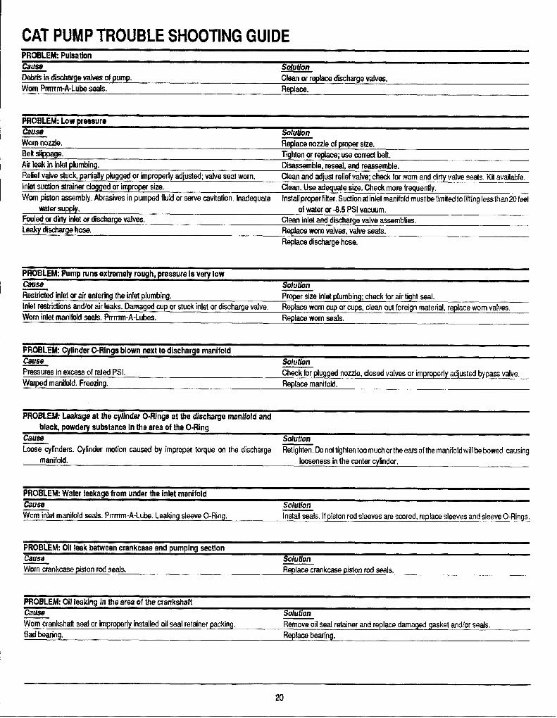
CAT FWMP TROUBLE SHOOTING GUIDEFRCMILEW pulsation
Csrma sdufkxr
Llabris irl diiharge Vafvee of prmp. Ckrarr or replaca discharge vafves.
Worn F%rrm-A-Luba saals. Replace.
PFWMWEM: Law mrrswrmCmrsa ‘ SohrtkrlrWwriMlozzkl Replace nozzle 01 propar size.Belt slippage. Tighten or replace; use corwcl belt.M leak in infrdplumbing. Disassemble, reseal, and reassemble.Relief vafve stuck, parmiaf!yplugged or impropdy adjusted; valve seat worn. Clean and adjust relief vdv~ check for worn and dirty wtve wits, Kti avahl%.Mel suction strainer clogged or improper size. Clean, Use adequate size. Check more frequently.Worm piston assmbly. Abrasives in pumped fluid or serve cavitation, Inadequate Instaflproperfifter. Suclionat inlet manifold must be fimittitofiftfng less ilmrr20fe$t
water W@y. of waler or -8.5 PSI wmr.rum.Fouled cs dirty inlet w dhcharge valves. Clean inlet and disdrarge vafve assernbfies.Ld%y db~ hose. Replace worn vafvss, vahre seats.
Raplarx dischwge hose.
tWIHLEhk IWrmr runs wdrentrdv rrmah. twessura Is verv low
-d inlet or air wdering the infe! plumbing.-Proper size inlet p[umbing; check for airtight S@
Intel restridions andhw air Iwks. Damaged oup or stuck inlet or discharge vafve. ReplaccI worn cup or cups, clean out foreign material, replace worn valves.
Worn inlet manifold seats. f%mrn-A-Luks. Recdars worn waka
PHOBLEM Cylinder (l-Flings blown next to discharge manifoldGwrstr Solution%sstwas in excx3ssof rated PSI. Check for plugged nozzle, dosed vafves or improperly adjusted bypass valve,
Warpad manildd, Freezing. Replace manifokf.
FWCNUEM: Leakage at tf’m cylinder C&RIngs at the discharge manifold andblack, powdory @stanca In the area of tfm O-Ring -
fame Solution
-~finders. Cyfinder motion causal by improper torque on the dischwge Retighten. Do nottightentoo much ortheears of the manifoidwil[bebovwc, causingmanifold. looseness in the center cylinder,
PROBLEM Watar leakage from under the inlet manifoldCmrsa !blu tion- --------Worn mht manifold seats. l%rm-A-LutM. Leaking sleeve O-Ring. Install seals, If piston rod sleeves are scored, replarx sleeves and SIWMWO-Rings,
PFWXW.EM: Clll Ioak betwrm crankcase and pumping sectionCarrsw !%luiian- ------ ..Wkwncwrnkcase piston rrxl seals. Replace crankcase piston rod seals.
fWt2f!fl.Ekk LNl leaking In the ma of the crankshaftCares SolutionWorn crankahafl swd or impmpe rly installed oil seal retainer packing. Remove oil seal retainer and replace damaged yrs.lwt and/or ~als.
Badbearing. Re@ace Mwing.
xi

CAT PUMP TROUBLE SHOOTING GUIDEPROBLEM: Exceealve r)lav In the end of the crankshaft oullav
!. ,,
cause SolutionWorn bail bearing from excessive tension on drive belt. Replace ball bearing. Property tension belt.
PROBLEiW Water In crankcasecause SolutionMay be caused by humid air condensing into water inside the crankcase. Change oil at 3 month or 500 hour intervals using Cat pump crankcase oil (other
qqwovad oil every month or 200 hours) P.N.: 06100.
Leakage oi manifold inlet seals arrd/or piston rod sleeves (Ming. Replace seats, sleeves and O-Rings.
PROBLEM: Oil leaking from underside of crankcasecause SolutionWorn wankcasa piston rod seals. Replace seals, sleeve and O+tings.
PROBLEM: Oil leaking at the rear portion of the crankcase
Cerise SolutionDamaged or improperly instatled oii gauge or crankcase rear cover O-Ring, and i%piace oil gauge or cover O-Ring, and drain plug O-Ring.
drain rriua O+ina.
PROBLEM Oii ieakage from drain plug&use SolutionLoose drain plug or worn drain plug ORing. Tighten drain plug or replaca O-Ring.
PROBLEM Loud knocking noise in pumpcause SoiutionPuliey ioose on crankshaft. Check key and tighten set screw.Broken worn bearing. Replace bearings.
PROBLEM Frequent or prematura faiiure of the iniet manifold seaisCause SoiutionScored rods or sleeves. Replace rods and sleeves.Over pressure to iniet manifold. Reduce inlet pressure per instructions.
PROBLEM Short cup iifeCause SoiutionAbrasive material in the fluid being pumped. Instaii proper filtration on pump inlet plumbing.Excmsive pressure and/or temperature of fluid being pumped. Check pressures and fluidinlet temperature; be suretheyare withinspecified range.Over pressure of pumps. Reduce pressure.Running pump dry. Do not run pump without water.Front edge of piston sharp. Repiace with new piston.
PROBLEM: Strong surging at the inletand Iowpressureon the discharge sidecause SolutionForeign parficiesintheiniet ordischargevaiveor worn inietand/ordischarge vafves, Check for smooth iap surfaces on inlet and discharge vaive seats, Discharge valve
seats, and inlet valve seats may be l-don a very tine oil stone; damagedcups and discharge valves cannat be lapped but must be replaced.
21
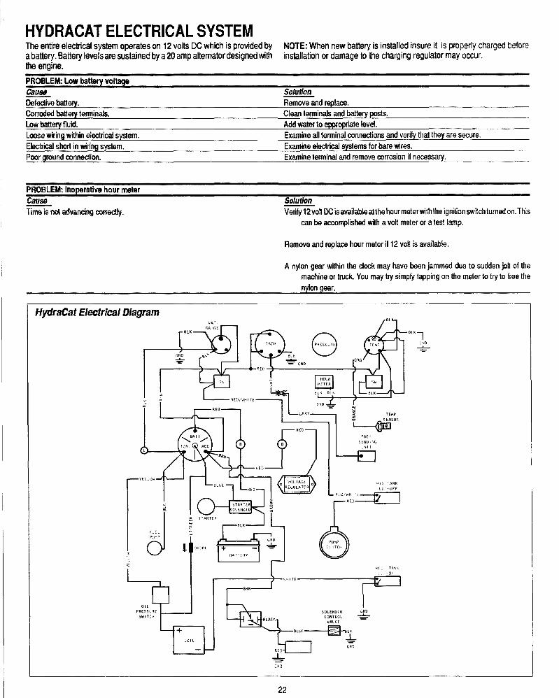
HY13RACAT ELECTRICAL SYSTEMTk entfro dectrical system operates on 12 volts DC which is provided by NOTE: When new battery is installed insure it is properly charg@dbeforea batttwy. Battwy Itwalsam sustained by a 20 amp alternator cfesignedwifh installation or damage to the charging regulator may occur.the engine.
FRW.EW M.nwba:twy voltag~Ctwfaa solution
&kXe MWY. Remove and [email protected] batteq wrrnirds. Ckn Ierminak and baMY pm+t$.Lowbatwry fluid. Add Wat6f to ~ cpriate Iml.
Lmxm wiring wkhin decfrid system. Examine all terminal concoctions and vwfiy thaf they are secure.
Elecfrii sharl in wirings@em. Examineelectricalsys!emsfor bare wires.PQQrground cnrmeciion. Examine Ierminal and remove corrosion if rwwwary.
PFNWLEM Inoperathm hour meter
cWa@ SoMrnfiml advancing cmedy. Verify 12volf DCisavailableatthe hourmetwviththeignition switch turned an.This
can be accomplished wth a volt meter or a test lamp.
Remove and replace hour meter if 12 volt is available.
A nyton gear withk the dcwk may have txwn jammed due to sudden joif of themachine or truck. You may try simply tapping on the m~ter lo try to free the
n~on gear.
,FICH
SENDING
JN!T
-yowl-lr-l‘-M=TkA I
H ?.&l= ‘r’”=11: -w- < A
IdFuEL 2PUMP
.:
2
&“[[ ,INK
I
,L, T ,>(r
OL1
PREsSURE 50 LENOI0 C~DSWITCH CONTROL *
VALVE
— +
COIL
%1 K
1GNO*
*GNO
22
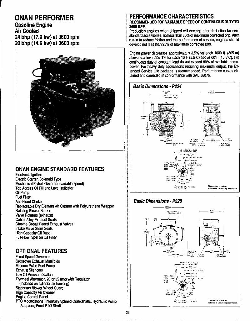
ONANPERFORMERGasoline EngineAir Cooled24 bhp (17’.9 kw) at 3600 rpm20 bhp (14.9 ‘k@ at 3600 rpm
ONAN ENGINE STANDARD FEATURESElectronic IgnitionElectric Starter, Solenoid TypeMechanical Flyball Governor (variable speed)Top Access Oil Fill and Level IndicatorOil PumpFuel FilterAnti-Flood ChokeReplaceable Dry Element Air Cleaner with Polyurethane WrapperRotating Blower SemenValve Rotators {exhaust)Cobalt Alloy Exhaust SeatsChrome Cobalt Faced Exhaust ValvesIntake Valve Stem SealsHigh Capacity Oil BaseFull-Flow, S@non Oil Filter
OPTIONAL FEATURESFixed Speed GovernorCrossover Exhaust ManifoldsVacuum Pulse Fuel PumpExhaust silencersLow Oil Pressure SwitchFlywheel Alternator, 20 or 35 amp with Regulator
(installed on cylinder air housing)Stationary Blower Wheel GuardHigh Capacity Air CleanerEngine Control PanelPTO Modifications: Internally Splined Crankshafts, Hydraulic Pump
Adapters, Front PTO Shaft
PERFORMANCE CHARACTERISTICSRECOMMENDED FOR VARIABLE SPEED OR CONTINUOUS DUTY TO3600 RPM.Production engines when shipped will develop after deduction for non-standard accessories, not less than 85% of maximum corrected bhp. Afterrun-in to reduce friction and the performance of service, engines shoulddevelop not less than 95% of maximum corrected bhp.
Engine power decreases approximately 3.5% for each 1000 ft. (305 m)atwve sea level and 1% for each 10°F (5.5W) above 60°F (15.5%). For
ntinuous duty at constant load do no~exceed 80% of av~lable horse-wer. For heavy duty applications requiring maximum output, the Ex-Ided Service Life package is recommended. Performance curves ob-ned and corrected in conformance with SAE J607b.
Dlm3tls!o”s,“ ,“chesnulllmeters shown m parfmmsss.
Basic Dimensions - P220
NO <032 “W 6 HOLES
E-GN A 267,,5, ?,,, . . w
,,4 .,,4 “ ,2WC0, .Ey
T
3!8 ?6 UK 4 HOLkS
-,250 {8?55,
[.37, ,6? 92, ,,,., ~,,63,.,1689?
D!menstons m mchwm,ll,meters show. m paremheses

ONAN ENGINE DETAILCyckx4Cylindm 2, horizonRa[lyopposedCmpmskm ma: 7.0 to 1Piston Spe@: 1800 fpm (9144 rnnls) at 3iNll rpmNat W@lgh& 127 lb (57.6 kg) dry, approximate.Brwlti’mf System: CIossd, recirculating.Cw.a!lng Systkwm FWMsum airooled, radial flow blower. Cooling air
volurm 1000 cim (1699 rnMw] at 3600 rpm.Fud Syst@rm Modwn downdraft carbur’otor with fixed main jet, limited
adjusfmvmt idle system. Smni-automatic choke operation with anti-fkmding featut’e. Combustion air required at3600 rpm, 50 cfrn (85 mVhr).
Gavwmcw bnsmts~odmm-~ardflv@ n.A~ustaNemecMniMl flybd,300 rpm drop to 3640 rpm.
Ign!don !?qrstwn: Solid state kweakerk?ssignition with fixed timing, 12 voltrmgative ground. RFI suppression spark plug wires meet UL and CSAint~rferencw requirements.
SMIWM: Positive engagement sdanoid type starter. 12 volt negativegruund.
Lukwfcat!on f3yst@n’KPositive displacement, gear-design oil pump. Fullpresw.m lubrication to main and connecting rod bearings and governor.FMd bypass, oil pressure control. Oil fill tube and level indicator.Removable aluminum oil base. Capacity, 2.7 qt (2.56 L); add 0.3 qt(0.3 L) for oil filler.
[email protected]’akMIW R@armount PTO pilot and keyed crankshaft extension.Rotation, CCW whtm facing PTO shaft. Front mount PTO pilot.
Main W.wftlgs: Steel-backed aluminum precision inserts, replaceable.I.D.: 2 in (50.8 mm); Length: 1 in (25.4 mm).
Camshaft: Cast iron alloy. Replaceable lead babbitt bearings (2).Conm?cting Rods: Forged steel. Replaceable bearings.Crankshaft Ductile inm. Machined-in oil passages. Simultaneous oil feed
from both ends of crankshaft.Cylindw’s, Crankcaaw Aluminum alloy with integrally cast pearlitic iron
cylinder tiners.CYIIIMM Hawk: Rerrwwable,aluminum alloy. High turbulence combustion
chamtwrs.PistIons: Aluminum alloy. Three ring, two compression, one oil control.
Cooled and Iubricat@dby oil spray.TqqwXs: Barrtit ty~, adjustable.Vabms: Exhaust, chome-cdbalt faced. Intake, steel alloy. Replaceable
valve guides.V$IIV6Seats: Replaceable@intake and exhaust.Valve lMMWurs: Exhaust valves.
GENERAL INFORMATIONEngine Mockil Refemrioa Identify your model by referring to the model ands~cificatir.m (spec Mter) as shown on the unit nameplate. Always usethesonumbers and the engine seria! number when making reference toyour engine.
HOW TO MM’ERPRH’ MODEL AND W+C !0
1234567
1. Factory code for general identification of basic engine series.2, Number of cylindtws.3. f3HP rating.4. Fual required (G= horizontal shaft, V = vertical shaft).5. Engine duty CYCIQ.6. Factory cm% for designated optional equipment, if any.?. Spwificaticm (SWC letter) which advances with factory
production modifications.
hcorrectservkw orreplacemefff ofparfs ~msultinsevorepnonaliflju~W/or equiprrwrrf damag~. .9?rviw personnel musf& qualtied fo ptwform3/ecfric4/ arWof mechanical servica
%X WEATHEROPERAT!QNNhen operating the engine in temperature above 1OO°F,pay particularMention to the following items to prewimt danaagw1. Keep the engine moling fins clean andfreeof obstruction.
W@ged or clogged cooiing fins car?cause ov.erfwating and engine darn-~ge. Ensure cooling fins are kepf clean and debris does nof accumulate.
Contact w“fh rotating machirwy can resulf in sewre flersonal im’urv ordeath Stayclearofr6tatilJg com@M@s ai?denwwe pro~ective shie~dsar?dguards are irr place and secured Mm? operating rn~chinery.
2. See that nothing obstructs air flow to and from the engine.3. Ensure that you are using the proper graok and weight of oil for ambient
temperatures. Check the oil level each time you fit the fuel tank.4. Check the battery water more frequently. High temperatures c-ancause
faster evaporation.5. Change crankcase oil and filter more frequently.
NM WEATHEFI QPERATK3NWhen the engine is being us@din temperatures bdmv 32°F (O°C),check thefollowing items closely:1. Use the correct grade and weight of oil for tk tmnperature conditions.
Change the oil only when the engine is warm.If an unexpectedW’nper-aturedrop occurs when the engine is filled with summer oil, beforestart-ing the engine, move it to a warm location until ‘the oil wfil flow frtmly,
2. Use fresh fuel. Fill the fuel tank after each day’suse to protect againstmoisturecondensation.
3. Keep the battery in a well-charged oondition.
DUST AND DIRT1.Keep unit clean. Keep cmoling system cl~an.2. Service air cleaner as frequently as required.3. Change crankcase oil and filter more than.
OUT-OF-SERVICE PROTECTIONProtect an engine that will be out-of-service tar more Man 30 days asfollows:1. Run the engine until it reachas normal operating tempwature.2. Turn off the fuel supply and run the @ngineuntil it stops.3. Drain oil from oil base while the engine is still warm. Refill with freshcrankcase oil and attach a tag stating viscosity wad.4. Remove spark plugs. Pour 1 ounm (2 tablespoons or 28 grams) of rust
inhibitor or SAE #50 oil into tie cylinders. Crank the engine over a fewtimes. Reinstall spark plugs.
5. Service air cleaner as outiin~d in tbfANfTENANCE.6. Clean governor linkage and protect by wrapping with a [email protected]. Plugexhaust outlet to prevent entmc@ of moisture, dirt, bugs, @tc.8. Wipe entire unit. Coat rustable parts with a light film of greasa or oil.9. Provide a suitable cover for the entire unit.
24

10. If battery equipped, disconnect and follow standard batterystorage procedure.
RETURNING UNfT TO SERVICE1. Remove cover and all protective wrapping. Remove plug from
exhaust outlet.2.Check tag on oil base andverifythat oil viscosity is still correct for existing
ambient temperatures.3. Clean and check battery. Measure specific gravity (1.260 at 770F[25%])
and verify level to be at a split ring. if specific gravily is low, charge untilcorrect value is obtained. If the level is low, add distilled water and chargeuntil specific gravity is correct.
4. Check that fuel filter and fuel lines are secure, with no leaks.5.Check that carburetor throttle lever and governor linkage move freely.6. Connect battery.7. Start Engine. Exhaust smoke is normal when the engine is started and
is usually caused by the rust inhibitor oil.
EXHAUST GAS IS DEADLY!Exhaust gases from all fuels (including diesel, gasoline, liquid propane,natural gas) contain carbon monoxide, an odorless and colorless gas.Carbon monoxide is poisonous and can cause unconsciousness anddeath. Symptoms of &rbon monoxide poisoning can include:
Dizziness 7hrobbing in TemplesNausea Muscular TwitchingHeadache VomitingWeakness and Sleepiness /nability to Think Coherently
IF YOU OR ANYONE ELSE EXPERIENCE ANY OFTHESE SYMPTOMS, GET OUT INTO THE FRESH AIR
IMMEDIATELY.
/fsymptomspersist, seek medicalattentrnn. Shutdown the unit and do notopwale untilithas baeninspectedandrepaired. Protection against carbonmonoxide inhalation includes proper instal/ation8 ventilation and regu/ar,frequent visual and audible inspections of the complete exhaust system.
Accidental starting of the engine can result in severe personal injury ordeath. Disconnect the negative battery cable and spark plug wires whileservicingengine, contiols, or associated equipment.
DAfLY CHECKS OR EVERY 8 HOURSThe operator should daily make a complete visual and audible inspectionof the engine. Check the following before starting the engine for the first timeeach day:1. Check all fuel lines and fittings for possible leakage.2. Inspect exhaust system for possible leakage and cracks. Locate leaks in
muffler and piping while fhe engine is operating. Repair all leaks immedi-ately after they are detected for personal safety.
3. Inspect air cleaner system for leaks. Make certain all clamps and fittingsare tight and free of potential leaks.
4. Checkcrankcaseoil Ievelwiththeengine off. Ifengine has been run, allowa minimum of 10 minutes for the oil to drain down before checking. If oillevel is at or below ADD mak on dipstick (Figure 1), add sufficient oil ofthe proper viscosity as specifiid in ENGINE SET-UP to bring oil level tothe FULL mark. Do not operate engine with oil level below the ADD markor above the FULL mark.
OIL SYSTEMCRANKCASE OIL CHANGERefer to Periodic Maintenance Schedule (located intheOperator’s Manual)for oil change interval. Ifoperating in extremely dusty, high ambient, or lowambient conditions, change oil more often.
Runengineuntii thoroughlywarm before draining oil. Stop the engine, platsa pan under the drain outlet and remove the oil drain plug. After the oil iscompletely drained, clean and replace the drain plug. Fill crankcase withcorrect amount of oil. Refer to SPECIFICATIONS for crankcase capacity.Use oils meeting the API classification SF, SF/C, or SF/CD. Refer to chartto determine the proper viscosity grade of oil to use Straight weight oils arerecommended for severe dutv use and at temperatures above 32°F KIWIfor minimum oil consumption-
.,
I Oil VkcosMy
—III 1
~f
, 1 I 1 1 1
F -20 0 20 40 60 60 100
c~”-”””-— “’ ‘“-10 0 70 — co K- –T
TEMPER~TuRERANGEYOUEXPECTBEFO~ENEXTOILCHANGE
Hot crankmse oilcan cause bums if ii comes in contact with skin. Wearprotective clothing and keep fingers and hands clear when draining oil
Excess oil can cwse high oil consumption, h@h operating temperatures,and oil foaming. Do not overfill crankcase.
Crankcase pressure can b/owouthotoi/, which cwcause severe personalinjury. Do not check oil while the engine is running.
Oil level should be to the FULL mark of the dipstick. Start engine and run fora short time to check for oil leaks around the drain plug.
25
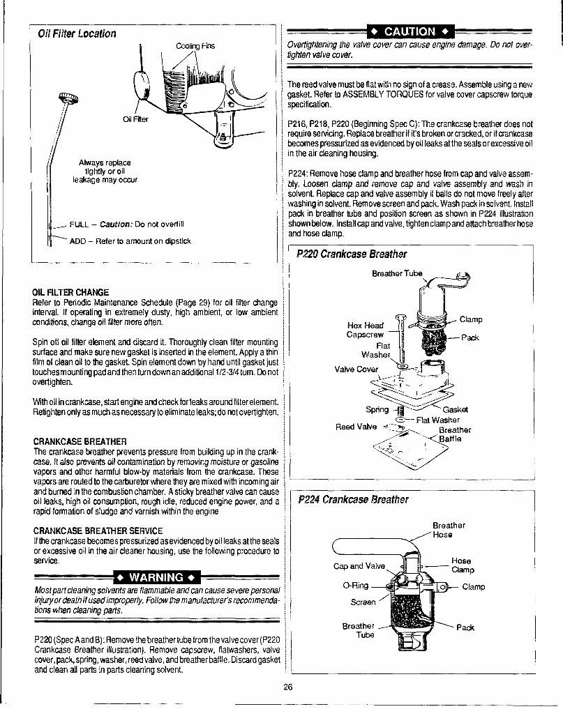
m Fmw’ Ltlcamfl
I
Oil
( Always replacetightly or oil
leakage may occur
1_ FULL -- C%ufk?n: Do not overfill
= ADD -- Refer to amount on dipstick
OIL FILTER CHANGERefer h PWiOdii2Maintenance Schedule (Page 29) for oil filter changlinterval. If operating in extremely dusty, high ambient, or low ambierconditions, change oil filter more often.
Spin oti oil filter element and discard it. Thoroughly clean filter mountinlsurface and make surenew gasket is inserted in the element. Apply a thifilm of clean oil to tho gasket. Spin element down by hand until gasket ju:touches rrmunting pad and then turndown an additional 1/2-3/4 turn. Do n(overtighten.
With oil incrankoase, statiengine and check for!eaks around filter elemenRetighten only as much as necessary to eliminate leaks; do not overtighter
CRANKCASE BREATHERTht? crankcaso breather pwents pressure from building up in the cranlcase. II also prevents oil contamination by removing moisture or gasolinvapors and other harmful blow-by materials from the crankcase. Thesvapors am routed to the carburetor where they are mixed with incoming aand burned in the combustion chamber. A sticky breather valve can causoil Ioaks, high oil consumption, rough idle, reduced engine power, andrapid formation of s[udge and varnish within the engine
CRANKCASE BREATHER SERVICE[fthe crankcaso becomes pressurized as evidt?nced by oil leaks at the seaor excessive oil in the air cleaner housing, use the following procedure 1service.
Mostpat’tdear?ir?gsdvenkaretlammab~eand can cause severe persorIinjury ordt?a!h ifi,wed imprcy?er~y.Fcdiowthe manufacturer’s recommend,tior?swhen cleaning parts.
P220(Spec A and H): Remove the breather tube from the valve cover(P22Crankcase Breather il[ustrafion). Remove capscrew, ffatwashers, valvcmmr, pack, spring, washer, reed valve, and breather baf~le.Discard gask[and clean all parts in parts cleaning solvent.
CWertighterring the valve cover can cause engine damage. QQno! owr-tighfen valve cover.
The reed valve must be flat with no sign of a crease. AssmMe using a rw?wgasket. Refer to ASSEMBLY TORQUES for valve cwer capscrew torquospecification.
P216,P218, P220 (Beginning Spot C): The crankcase breathw’ does notrequire swvicing. Replac@breather if it’s broken or cracked, or if crankcasobecomes pressurized as evidenced by oil leaks at the seals or excessive oilin the air cleaning housing.
P224: Remove hos@clamp and breather hose from cap and valve assem-bly. Loosen clamp and remove cap and valve assembly and wash insolvent. Replace Mp and valve assembly if balls do not move freely aftwwashing insolvent. Remove screen andpack. Wash pack insolvent. Installpack in breather tube and position screen as shown in P224 illustrationshown below. Install cap and valve, tighten clamp and attach breather hoseand hose clamp.
RHOcrankcase Bn?ath?r
Val
_C3-- Flat WasherRead Valve -?=v Brteath@r
o
/Baffle
~.~’n , \-..
‘-,.%’-
1
f3reatherHose
(-
mp
26

IGNITION iSPARK PLUGS Refer to Periodic Maintenance Schedule for sparkplug ~ SOLID STATE lGNfTION: Ignition timing is set at the factory and is notservice interval. Replace spark plugs that show signs of fouling or electrode ! adjustable. The solid state ianition components are not adjustable anderosion. Refer to S“Wcifi~tions fo; spark plug gap. ~ n+uire no routine maintenan-~. ‘
J=’0.025” G8p
+-
Ground E?ectmde
Servicing Spark Plug
Worn: On a worn Dlua. the center electrode WIII berounded and the iap-will be eroded .010 or more than
the correct gap. Ffeplace a worn spark plug Immediately
Carbon Fouled Soft, sooty, DlacK aeposms malcaterecomplete combustion. Incomplete combustion !s
usually caused by overnch carburetion, weak ignltton,or poor compression
Normab A plug faken from an engine operating undernormal conditions will have light tan or gray coloreddeposits H the center electrode is not worn, a plug inthis condition could be regapped and reused.
Wet Fouled: A wet plug is caused by excess fuel, or oilin the combustion chamber Excess fuel could becaused by operating theeng!ne with too much choke
Oil in the combustion chamber IS usually caused byworn piston rings or valve guides.
Chalky White Deposits Chalky white colored depositsIndicate overheating This condition IS usuallyaccompanied by excesswe gap erosion A clogged gra:
screen, clogged cooling fins, and lean carburefion aresome causes of over-hemmg
SPARK PLUGS CONDITION DIAGNOSISEngine misfire or starting problems are often caused by spark plugs in poorcondition or with improper gap setting.
SERVICEEvery 100 operating hours remove the spark plugs, check condition, andreset gaps or replace with new plugs as necessary (see illustration above).
1. Before removing the spark plugs, clean the area around the base of plugsto keep dirt and debris out of the engine.
2. Remove the plugs and check condition. Replace the plugs if worn or ifreuse is questionable.
Do noi clean the sparkplugs in a machine using abrasive grit. Some gritcould remain in spark p/ugs and enfer the engine causing extensive wearand damage.
3. Check the gaps using a wire feeler gauge. Mjust gaps to 0.025” bycarefully bending the ground electrode.
4. Reinstall the sparkplugs into cylinder heads. Torque plugs to 10/15 ft. lb.
INSPECTIONInspect the spark pfugs as soon as they are removed from the cylinderheads. The deposits onthetips are an indication of the general condition ofpiston rings, vafves, and carburetor. Normal and faulty spark plugs areshown in the photos shown above.
Refer to Periodic Maintenance Schedule (Page 29) for cooling systemservice interval. Clean cooling fins and chaff screen sooner if required.Remove any dust, dirt or oil which may have accumulated.
EXHAUST SYSTEMMake regular visual andaudibleins~ctionsof the exhaust system through-out the entire life of the engine. Locate leaks in muffler and piping while theengine is operating. Repair all leaks immediately after they are detected forpersonal safety.
Breathing exhaust gases can result in severe personal injury or death./nspectexhaust system audibly and visualiyforleaks daily andrepairleaksimmediately.
AIR CLEANERELEhlEtW Refer to Periodic Maintenance Schedule (Page 29) for aircleaner service and replacement interval. Service or replace more oftenwhen operating under severe operating conditions. Service by gentlytapping element (see illustration on next page) on a flat surface.
ELEMENT WRAPPER (ff Equipped): Refer to Periodic MaintenanceSchedule (Page 29) for element wrapper service interval. Wash in waterand detergent and squeeze dry fike a sponge. Ring with water. Allow to dry,
(C0ntinm32, nextpage)
27
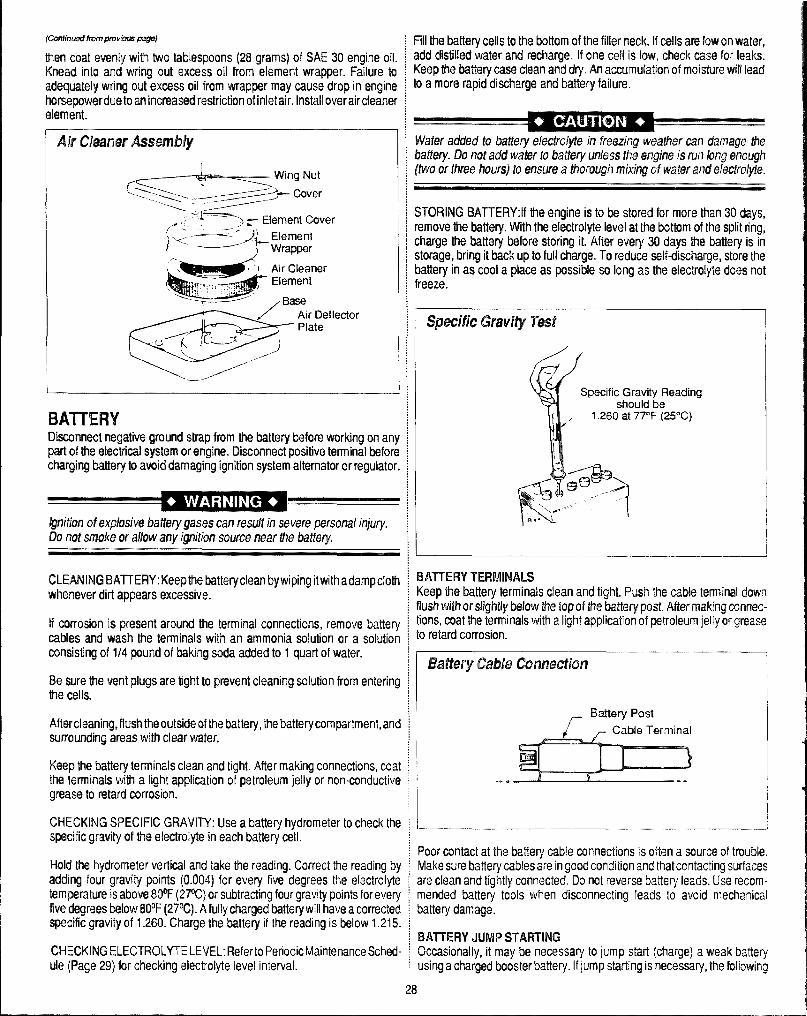
fcmlimdfrom#+wkw6 J2sgtl)
thwrcoat mmriy with two tablespoons (28grams)ofSAE30engineoil.Km?adinto and wring out IBxci?ssoil from element wrapper. Failure toadoquab?ly wring out oxoess oil from wrappm’ may cause drop in enginehorsepowerduoto an incfieased restriction of ir’ktair. Install ovwaircleanero[ament.
“-’ ‘rc’canertidy=’
BATTERYOkconnect rregativo ground strap from the battery before working on anypart of tfm electrical system or engine. Disconnect positive terminal beforecharging battery to avoid damaging ignition system alternator or regulator.
CLEANING BATTERY: Keep ttw?batteryclean by wiping itwith a damp ciothwhiwwer dirt appears excessive.
If cmosim’1 is present arcwmd the terminal connections, remove batterycables and wash the terminals with an ammonia solution or a solutionconsisting of 1/4 pa-red of baking soda added to 1 quart of water.
Ha N.re th@wentplugs are tight to prevent cleaning solution from enteringthe cells.
Afl@rcleaning, fksbthe outsideof the battery, the battery compartment, andsurrounding areas with ckar water.
Keep the battery terminals clean and tigh!. After making connections, coatthe Wminak with a 6ighlapplication of petroleum jelly or non-conductivegreas@10retard corrosion.
CHECKING SPECIFIC GRAVITY: Use a battery hydrometer to check thespecific gravity of tlw el@ckolyte in each battery cell.
Hold the hycfrwneter vertical and take the reading. Carrect the reading byadding four gravity points(0.004)for evey five degrees the electrolytetemperature is above 130°F(2PC) or subtracting four gravity points for everyfiv@dagmes b@mv8@F (27%). A fully charged battery will have a correctedspt?cik grawity of 1.260. Charge the battery if the reading is below 1.215.
CHECKING ELECTROLYTE LEVEL: Refer to Periodic Maintenance Sched-ule (Page 29) for checking electrolyte level interval.
Fill the battery cells to the bottom of the filler neck. If CWIISare low on water,add distilledwaterand recharge. If one cetl is low, check cast? for leakKeep the battery case clean and dry. An accumulation of moistww wilt leadto a more rapid discharge and battery failure.
STORING 13ATTEllY:lf the engine is to be stor~d for more than 30 days,remove the battery. With the electrolyte level at the bottom of th@split ring,charge the battery before storing it. After every 30 days tlw battery is instorage, bring it backup to full charge. To reducxeselfdischarge, store thebattery in as cool a place as possible so long as the electrolyte does notfreeze.
L
Reading‘%(25”C)
BATTERY TERMINALSKeep V%?battery terminals clean and tight. Push the cable terminal downflush with or stightly below tie top of the battery post. Aft@rmaking connec-tions, coat the terminals with alight application of petroleum jelly or greaseto retard corrosion.
,/’-Battery Post
,-- Cable Terminal
Poor contact at the battery cable connections is often a source of trouble.~ Make sure battery cables are in good conditicm and that contacting surfaces~ are clean and tightly cmnected. Do not reverse batfe~ leads, Us@reconr-~ mended battery tools when disconnecting leads to avoid mechanical~ battery darr~ag@.
~ BATTERY JUMP STARTING: Occasionally, it may W necessary to jump start(charg@]a weal{battery~using a charged booster battery. If jump starting is necessary, the following
28
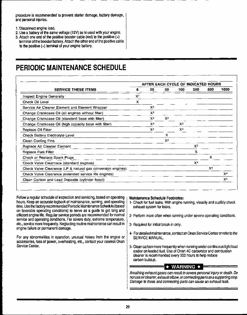
procedure is n?commended to prevent starter damage, battery damage,and personal injuries.
1. Disconnect engine load.2. Use a battery of the same voltage(12V) as is used with your engine.3. Attach one end of the positive booster cable (red) to the positive(+)
terminal of the booster battery. Attach the other end of the positive cableto the positive(+) terminal of your engine battery.
PERIODIC MAINTENANCE SCHEDULE
AFTER EACH CYCLE OF INDICATED HOURS
SERVICE THESE ITEMS 8 25 50 100 200 500 1000
Inspect Engine Generally xl
Check Oil Level x
SerViCe Air Cleaner Element and Element Wrapper )(2
Change Crankcase Oil (all engines without filter) X2
Change Crankcase 011 (standard base with filter) X3 X2
Change Crankcase Oil (high capacity base with filter) X3 X2
Replace Otl Filter )(3 Xz
Check Battery Electrolyte Level x
Clean Cooling Fins Xz
Replace Air Cleaner Element )(2
Replace Fuel Filter x
Check or Replace Spark Plugs x
Check Valve Clearnace (standard engines) X4
Check Valve Clearance (LP & natural gas conversion engines) )(4
Check Valve Clearance (extended service life engines) X4
Clean Carbon and Lead Deposits (cylinder head) )(5
Follow a regular schedule of inspection and servicing, based on operatinghours. Keep an accurate logbook of maintenance, serving, and operatingtime. Usethefactoryrecommended Periodic Maintenance Schedule (basedon favorable operating conditions) to serve as a guide to get long andefficient engine life. Regular service periods are recommended for normalservice and operating conditions. For severe duty, extreme temperature,etc., service more frequently. Neglecting routine maintenance can result inengine failure or permanent damage.
For any abnormalities in operation, unusual noises from the engine oraccessories, loss of power, overheating, etc., contact your nearest OnanService Center.
Maintenance Schedule Footnotes:1- Check for fuel leaks. With engine running, visually and audibly check
exhaust system for leaks.
2-Performmore often when running under severe operating conditions.
3- Required for initial break-in only.
4- For detailed maintenance, contact an Onan Service Centerorreferto theSERVICE MANUAL.
5-Clean carbon more frequently when running under continuous light loadand/or on leaded fuel. Use of Onan 4C carburetor and combustioncleaner is recommended every 200 hours to help reducecarbon buildup.
Breathrhg exhaust gases can result in severe personal injury or death. Donotuse aircleaner, exhaustelbow, orconnectingparts asa supporting step.Damage to these and connecting pads can cause an exhaust leak.
29
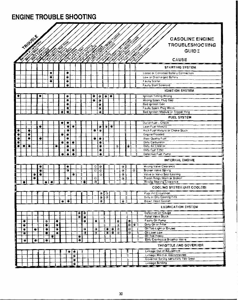
TROUBLE SHOOTING
IGNITION SYSTEM
30—

ENGINE TROUBLE SHOOTINGGUIDEWherrtroublesoccur, be sure tocheckthe simple causeswhich, at first, mayseem too obvious to be considered. For example, a starting problem couldbe caused by an empty fuel tank.
Some common causes of engine troubles are fisted Mow-use this asaguide to locate causing factors.
PROBLEW.Engine cranks but will not startSolutionEmpty fuel tank.Clogged fuel line.Spark plug leads dsconnscted.Keyswitch or kill switch in “off position.Faufty sparkplugs.
Fauftv ianition module,Dirt or water in fuel svstem.
PROBLEM Engine starts but does not keep runningSolutionRestricted fuel tank venl.Dirt or water in fuel system.Fauhy chake or throtile controls.kables.Loose wires or connections which kill terminal of ianition module to around.Cshuretor improperly adjusted.Fautty cylinder head gaskets,Faufty fuel pump.
PROBLEM:Engine starts hard
Soiutionhose wires or connections.Dirt or waler in fuel svstem.
Cloggedor restricted fuel lines.Faulty choke or throttle cantrolsksbles.Faulty spark plugs.Carburetor improperly adjusted.Incorrect vafvc+t~teppet deerence.Low compression.
PROBLEM:Enaine will not crank
Battery is discharged.Loose or fauffy wires or connections.Faufty keyswitch or ignition switch.Faulty electric starterktartar solenoid.Seized internal engine components.
PROBLEM Engine runs but missesSolutian------ ..Dirl or water in fuel system.Spark plug leads boss.Loose wires or connections which intermiltentlyshorl killterminal of ignitionmodule
to ground.Carburetor imorooerlv adiusted.
Engine overtreating.Incorrect vafvstcAappet dearsnce.Faulty gnition module.
PROBLEM Engine wfll not idleSolution------ ..Idfe speed adjusting screw improperly set.Dirt or water in fuel system.Idle fuel adjusting screw improperly set.
Restricted fuel tank vent.Faultv soark DIUOS.Incorrect vafveto-tsppst dearsnce.
Low compression
PROBLEM:Engine overheatsSoiulionGrass screen, cooling tins, or shrouding clogged.Excessive enaine load.Low crankcase oil level.High crankcase oil level.Carburetor improperly adjusted.
PROBLEM: Engine knocksSoiutionLow crankcaseoil level.Excessive enaine load.
PROBLEM Engine loses powerSoiutionLow crankcase oil Ievet.High crankcase oil level.Restricted air cleaner etement.Dirl or water in fuel line.Excessive engine load.Enaine overheatingFaultv soark oluas,
Carburetor improperly adjusted.Low compression.
PROBLEM:Engine uses excessive amount of oilSoirrtionIncarred oil viscositv of twre.
Cloaaed or imorcmerfvassembled breather svstem.Worn or broken piston ringsWorn cyliiderbares.Worn valve stems and/or vefve guides.
31

MAINTENANCE PFKKEDl!REST~ avoid costly mpaim and down-time, it is imperative to develop andpracti~ good mainttmarm procmfuwis from the beginning. These proce-dures fall into daily, WWWIY,monthly and quarterly increments, and aremdirwd twlmv. W@have provided a maintwwmca log for your convenienceon next pag@;it is remwmww.!ed that you affix a copy of the logon thewhit% door rmar your unit for convenience and to sawe as a maintenance
Check engine oil Iwal.IHSWCIgarden hose screen-clean as needed.Visually inspect machine for loose wires, ail leaks, water leaks, etc.Inspect recavery tanks/s filter and filter bag for tears, holes, etc. - clean,
repair or rapface as needed.‘Lubricate blower wi!h Penrwguard through blower inlet.
WEEKLYChange engine oil. (25-30 hours of operation.)Check engirw air clwmer filter - clean as necessary.Check high pressure pump oil - add as necessary.Check drive coupler set screws - tighten as needed.Check pump driw belt for wear-tighten as needed.Check pump pulleys - tighbsn as needed.Check fuel lines far wt%irlchafing.Check all nuts and tmlts - tighten as needed.Check heater burrow assy. union for tightnessdeaks.Cl@anvacuum tank thoroughly with high prwssuw washer.Flush watw and chemical system with 50/50 while tinegar solution.Check @ngirwRPM’s - adjust102W0 rpm on 4.5
2800 rpm on 4.0MONTHLYthwrseblower bearing fittings.Rwnove pressure bypass valve stem, grease cup and stem, reinstall.Ctwk water !evol in battery. Clean connections as needed.
aumww’t’Cmge oil in blower.Check engine compression.Check for combustion chamber carbon deposit.Change spark plugs.
WJWTA?W:Reoimd date and machinehours on maintenance@chart.
OVERALL CARE OF UNITMAIW’AINING WE (XWWJAL IWWWWCE W W3LM UNIT !SMPORTAMT FOR IWO REASONS1.Itrepn%+antsa big dollar investment for your c%mning business and its
appearanrx? should reflect that fact. A dirty machirm is not pmkwional!
2. Maintenance, troubleshooting, and repair is much easiw’ to accmpliahon a clean well maintairwd unit. f%?gularcl~aning of MOmwhinf!offwsyou an opportunity to visually insp?ct al! facets of th~ machim and spotpotential problems before tfwy ocfwr.
FOLLOWfNG MAMTEIWNCEM RECWMBIEMDED BYTHEMMUFAC.TLJRER AT THE FREQUENCY INDICATED.
AKER EACH JOB:Check recovery tank, slsl filter and filter bag as required.
fMfLY:Wipe machine down thoroughly with a damp cloth; flush recovwy tank outthoroughly. Empty filter bag and inspxt for rips, @ars, @tc.- replace asneeded; remove, thoroughly clean and r~install stainless steel fillerscretmin recovery tank; inspect and clean vacuum slot on cleaning wand; clwckwand head for sharp edges that could tear carpal - file down as needed;clean wand to maintain original appearance; wipe down vacuum andhighpressure hoses as needed-visually inspect for cuts, etc.
WEEKLY:Wipe down entire unit as needed- apply good coat of auto wax 10all paintedsurfaces inside and out, and to control panel; thoroughly cfwan recoverytank using high pressure hot water (unit with optional high pressure c{eaninggun may be used for this}; removo stainless steel filttw in recovery tank,thoroughly clean removing all IMt build-up, ins~ct fordamageandreinstall.Remove filter bag, Thoroughly clean and reinstall - iFtarn,repkmo; @mptychemical from chemical contakwr, wash out thoroughly to remove anychemical build-up; inspect chemical feed Iirm strainer and use W% whilevinegarhvater solution to remove any chemical build-up; thoroughly cl@anwand and inspect for clogged jet, debris in vacuum slat and l@akingfitingsat valve. Apply light coat of auto wax to wand. Thoroughly dean vacuum andhigh pressure hoses including hose cuffs - inspect for wear or damage tohoses and quick connect fittfngs. Inspect garden how corwwctladapterscreen for debris, remove and clean thoroughly. Inspect all firms fwiwararabrasions that may cause possible leaks.
32

MAINTENANCE LOGDAILY CLEANING & INSPECTIONEngine oil - check Clean vac tank filter bag after every jobGarden hose screen - clean Blower inlet - spray with LPS 1 atter last jobMachine - general inspection
WEEKLY SERVICE
MAXHRS
SERVICE I DATE/1-lRS I DATE/HRS I DATE/HRS I DATE/tiRS I DATE,HRS I DATE/HRS I DATE/HRS
25 BLOWER check 011level25 PUMP OIL check (lop of sight gauge)25 DRIVE SHAFT SYSTEM tighten set screws25 BELTS & PULLEYS check tightness25 HIGH PRESSURE LINES check for chafing25 NUTS & BOLTS check fightnese25 13ATTERY LEVELS check25 VACUUM TANK clean25 WIRING check for chafting25 CHEMICAL SYSTEM flush wlvinagar
MONTHLY SERVICE
100 ENGINE OIL change100 BLOWER greasa bearing100 ENGINE AIR CLEANER clean100 BY PASS VALVE grease cup & stem
QUARTERLY SERVICE (3 MONTHS)
300 BLOWER OIL change300 ENGINE cmmcrreaaion300 SPARK PLUGS change
MAINTENANCE LOGDAILY CLEANING & INSPECTIONEngine oil - check Clean vac tank filter bag after every jobGarden hoee ecreen - clean Blower inlet - spray with LPS 1 after last jobMachine - general inspection
WEEKLY SERVICE
MAXHRS
SERVICE I DATE,HRS I DATE/HRS I DATE/FIRS [ DATE,HRS I DATE/HRS I DATE/HRS [ DATE/HRS
25 BLOWER check oil level25 PUMP OIL check (top of sight gauge)25 DRIVE SHAFT SYSTEM tighten set screws25 BELTS & PULLEYS check tightness25 HIGH PRESSURE LINES chock for chafing25 NUTS & BOLTS check tightnese25 BATTERY LEVELS check25 VACUUM TANK clean25 WIRING check for chaffing25 CHEMICAL SYSTEM flush w/vinagar
MONTHLY SERVICE
100 ENGINE OIL change100 BLOWER grease bearing100 ENGINE AIR CLEANER clean100 BY PASS VALVE grease cup & stem
QUARTERLY SERVICE (3 MONTHS)
300 BLOWER OIL change300 ENGINE compression300 SPARK PLUGS change
33

MAINTENANCE MMDAILY GLREANING & INSPECTIONEngine od - check Clean vac tank filter bag alter every jobGarden hose screen - clean Blower relet - spray with LPS 1 after last jobMachu’m - cwmmral mstmctiorf
WEEKLY !3ERVICE
MMHR-S
SEIWN2E ] DATEIHRS I DATEHRS I DATE HRS I DATE(HRS I OATEFIFIS I f)ATEIHflS I OATEMWi
25 BLOWER check ml level25 PUMP OIL check (top 01 mght gauge)2s lXWVE SHAFT SYSTEM ughterr set screws25 BELTS & PULLEYS check ughtrress25 HIGH PRESSURE LINES check for chafing25 NUTS & BQLTS check lightness25 SATTEFW LEVELS check2!! VACUUM TANK clean25 WIH lf’#3 check tor chaffing25 CkfEMICAL SYSTEM flush wlvmegar
MONTHLY SERVICE
100 ENGINE OIL change100 EILOWER grease bearing1cm ENGINE AlR CLEANER clean1(M f3Y PASS VALVE grease cup & Slem
QUARTERLY SERVICE (3 MONTHS)
300 BLOWER OIL change300 ENGINE comrwessmn300 SPARK PLUGS change
MIAMH4ANCE LOGDAILY GLEAMING & IW3PECTIONErmine ail - check Clean vac tank filter baa after everv 10bGakm hose screen - clean Eflawer relet - spray w!t~ LPS 1 after ‘last 10bMachine - general inspectlan
WEEKLY SEFWICE
MAXfms SERVICE I DATE1-lRS I DATEIHRS I DATEI-IRS I DATE HRS I DATEHR5 I DATE/lil15 I fJATE/flRS
-- . . . ... .. -. .W-..
25 PUMP OIL Cheo25 fW7WE SHAFT :25 BELTS I%PllLLE25 HIGH ‘----’ ‘->5 MlITS
‘-E25 ml-r25 VAL2196 WISSI1
k (top of sqhi gauge) I I)YSTEM tqhvan sel screwsiY!3 check ttghtneSS
v rrcam.Jr4E LINES check for chafing; & f3CIL.TSc!!eck t!ghtnessERY LEVELS checkJLfMTANK cfean
_ ..,. ...VG chock for chaff{ng25 CHEMIICAL SYSTEM flush w/vinegar
MClt4TH’LV SEIRVICE
t00 ENGINE OIL change100 BL(IWER Qfiease bearing100 ENGINE AIR CLEANER ciean100 EYYPASS VALVE grease cup & stem
CWkHTERLY SERVICE (3 MONTHS)
300 BLOWER OIL change300 ENQI NE compression300 SPARK PLUGS ctrange
34
I

NOTES
35
wAJw’wrrY INFORMATION WARRANTY PROCEDURETo avoid misundwWandings which might occur between machine ownersand rnanufachrn?r, vm are listing causes of component failure that specifi-cally voids warranty coverage. Such causes as listed below shall constitutealluw ar Iw2glli!ct.
MLQWER: Failuw to lubricate impllers daily with LPS-1 or WD-40 lubri-cant. Failure to lubricatekarings as recommended in blower marwrat.Failure to maintain proper oil levels in the blower. Failure to use the correctoil grado and viscmity as recommended in blower manual. Failure toproperly maintain Mower safeguard syslems such as waste tank filterscrwm, vacuum safety relief valve and waste tank automatic shut-offsystwn. Allowing foam to pass through blower.
HIGH PFIESSLME WATER PUMk Failure to maintain proper oil level asrecammonded in pump manual. Failure to change oil in pump at recom-mended intervals. Failure 10 protect pump against freezing. Failure tomaintain pump fwotection shutdf system. Failure to use water softener inhard water areas. (he of improper chemicals.
VAC ‘TANK Failure to properly maintain filtering devices in tank. Failure toclean tank as recommended by manufacturer. Failure to maintain vacuumSafaly mleas% in tank lid. U% of improper chemicals.
CHEMICAL PROWJRTIQNEF!: Use of improper chemical. Failure to usewater softoner in hard water area. Qperating machine without properchemical filter screen. Failure to prot~ct against freezing.
CtlNTRflLPANEh Failr.wetoprotect ffowmeterandwaterpressuregaugeagainst freezing.
VACtJWd AN12 SOLUTION HQSE~ Failure to protect hoses againstfreezing. Failure to protect hoses against burns from enginelblower ex-haust. Damag6 to Iwws from being run over by vehicles. Kinking orcracking from failure !oslwworunroll hoses ctrrmctfy. Normal wear and tearfrom everyday use.
CLEANING WJMW Failure to protect against freezirrg. Clbviousphysicalabu!w of wand.
WATER HEATER Cwer pressurization of the system (recommendedmaximum working pressure -800 PSI]. Failure to protect against freezing.Modification of the gas delivery system.
Warranty coverage is available to you ONLY through HydraMaster CorW.ration, 20309 t%$thAve. West, Lyrmvmd, Washington 98036. When war-ranty parts are needed, write Hydrafblasttw Wtwrm!y [email protected] the aboveaddress, or call the Warranty/S.ervke Dept. at (20$} 775-7275. No calloctcalls will beacceptecf, Hours of WarrantylSarwiae Dept. am 8:00 am to5:00 pm Pacific Time.
kWORTANT: HydraMasttWs warranty policy provides replacwmnt partswithout charge for thirty (30] daystocustomws maintaining cunwntaccwntstatus. An invoice datedthirty(30)days from date of replacenwmt partsshipment will be sent to the customer for the amount of the parts sent. Thecustomets faulty parts must m returned far evaluation ptior to the @xpira-tion of the thirty (30) day period, Upon warranty approval, a credit will bissued the customer for the replacement parts invoice. Warran~ dlmppmal or failuro to return ha faulty parts wltlln the thirty (30] duyperiod allowed w[[I result in the customer Wring charg~d for W@replacement parta arm
I
36

GOLDEN GUARANTF+@LIMITED
WARRANW PUNHydraMaster warrants truckmcrunt machines of its manufacture to be free from defects in material and workmanship if properlyinstalled, maintained, and operated under normal conditions with competent supervision. No person, agent, representative ordealer is authorized to give any warranties on behalf of HydraMaster nor to assume for HydraMaster any other liability inconnection with any of HydraMaster’s products. This warranty shall extend to the original purchaser of said equipment for theperiods listed by component below from date of installation. If repairs or replacements are made by tbe Purchaser withoutHydraMaster’s written consent, Hydramaster’s warranty shall cease to be in effect. No allowance will be granted for any repairsor alterations made by the Purchaser without HydraMaster’s prior written consent.
Machinery, equipment and accessories furnished by HydraMaster, but manufactured by others, are warranted only to the extentof the original manufacturer’s warranty to HydraMaster.
HydraMaster agrees at its option to repair at the point of shipment, or to replace without charge any parts or parts of products ofHydra Master’s manufacture, which withi n the specified warranty period shall be proved to HydraMaster’s satisfaction to have beendefective when shipped, provided the Purchaser promptly notifies HydraMaster, in writing, of such alleged defect. HydraMxiterwill pay all freight and transpiration charges, via normal ground shipping means, for replacement of parts covered under thiswarranty. This warranty covers parts, as specified, and does not cover labor which may be necessary in completing repairs.HydraMaster’s liability to Purchaser, whether in contract or in tort arising out of warranties, representation, instructions, or defectsfrom any cause shall be limited to repairing or replacing the defective part or parts. To qualify for warranty coverage, defectiveparts must be returned to HydraMaster within 30 days. No liability whatsoever shall attach to HydraMaster until said productshave been paid for.
Except as stated in this section and in the preceding section titled “Warranty” and except as to title, there are no guarantees orwarranties of merchantability, fitness, performance or otherwise, express, ireplied or statutory, and Hydra Master shall have noliability for consequential, incidental or other damages, howsoever caused.
FRAMEYCOVER wsEMBLm: .......................................................................................................................................................................3 years
VACUUM RECOVERY TANWCHEMICAL MIX TA~: ........................................................................................................................3 years
ENGINIU(?ivougtI originalManufwhmz. On f)irwt Orkunits SE orisind Mmufwhm+s wamanty.) . . . . . . . . . . . . . . . . . . . . . . . . . . . . . . . . . . . . . . . . . . . . . . . . . . . . . . . . . . . . . . . . . . . . . . . . . . . . . . . . . . . . . . . . ..z YW3fS
VACUUM BLOWER: (’fhmJsIIorigin.]Manufacturer. scc ccmpcr tnrtustics W.y.) .....................................................................................................2 yFXNS
CHEMICAL PROPORTIONING SYS~M: ....................................................................................................................................................l yew
CLEANING WA~ ............................................................................................................................................................................................... 1 year
INTERNAL MACHINE HOSW ......................................................................................................................................................................... 1 year
HIGH PRESSURE BY PASS VALVE ................................................................................................................................................................ 1 year
EXTERNAL MACHINE HOSE’S ........................................................................................................................................................................l year
BELTS, FITTINGS, FfLTER SCREENS, GAUGES ..................................................................................................................... .................. 1 year
WATEH HEATER OR HEAT EXC~NG~ .................................................................................................................................................l year
HIGH PRESSURE PUMP.(?brougtI on@MtManda@w) ..........................................................................................................................................l year
AII components not specificallyy referenced in the above schedule are covered under this warranty for a period of one (1) year, exmpting those partswhich are considered, by HydraMaster, to be expendable in normal use.
Freezing of any water or chemical related romponent will VOID all warranties on waterer chemical related components. internal or external. of thisequipment.
Deposits and build-up in the water system, chemical system or beater system due to hardness in tbe water used or chemicals which result in deposits,will void all warranties on affected components.