hydra series ii data bucket - testworld inc. series ii data bucket users manual pn 686698 ......
TRANSCRIPT

®
2635AHydra Series II Data Bucket
Users Manual
PN 686698November 1997© 1997 Fluke Corporation, All rights reserved. Printed in U.S.A.All product names are trademarks of their respective companies.

LIMITED WARRANTY & LIMITATION OF LIABILITY
Each Fluke product is warranted to be free from defects in material and workmanship undernormal use and service. The warranty period is one year and begins on the date of shipment.Parts, product repairs and services are warranted for 90 days. This warranty extends only to theoriginal buyer or end-user customer of a Fluke authorized reseller, and does not apply to fuses,disposable batteries or to any product which, in Fluke’s opinion, has been misused, altered,neglected or damaged by accident or abnormal conditions of operation or handling. Flukewarrants that software will operate substantially in accordance with its functional specifications for90 days and that it has been properly recorded on non-defective media. Fluke does not warrantthat software will be error free or operate without interruption.
Fluke authorized resellers shall extend this warranty on new and unused products to end-usercustomers only but have no authority to extend a greater or different warranty on behalf of Fluke.Warranty support is available if product is purchased through a Fluke authorized sales outlet orBuyer has paid the applicable international price. Fluke reserves the right to invoice Buyer forimportation costs of repair/replacement parts when product purchased in one country is submittedfor repair in another country.
Fluke’s warranty obligation is limited, at Fluke’s option, to refund of the purchase price, free ofcharge repair, or replacement of a defective product which is returned to a Fluke authorizedservice center within the warranty period.
To obtain warranty service, contact your nearest Fluke authorized service center or send theproduct, with a description of the difficulty, postage and insurance prepaid (FOB Destination), tothe nearest Fluke authorized service center. Fluke assumes no risk for damage in transit.Following warranty repair, the product will be returned to Buyer, transportation prepaid (FOBDestination). If Fluke determines that the failure was caused by misuse, alteration, accident orabnormal condition of operation or handling, Fluke will provide an estimate of repair costs andobtain authorization before commencing the work. Following repair, the product will be returned tothe Buyer transportation prepaid and the Buyer will be billed for the repair and returntransportation charges (FOB Shipping Point).
THIS WARRANTY IS BUYER’S SOLE AND EXCLUSIVE REMEDY AND IS IN LIEU OF ALLOTHER WARRANTIES, EXPRESS OR IMPLIED, INCLUDING BUT NOT LIMITED TO ANYIMPLIED WARRANTY OF MERCHANTABILITY OR FITNESS FOR A PARTICULAR PURPOSE.FLUKE SHALL NOT BE LIABLE FOR ANY SPECIAL, INDIRECT, INCIDENTAL ORCONSEQUENTIAL DAMAGES OR LOSSES, INCLUDING LOSS OF DATA, WHETHERARISING FROM BREACH OF WARRANTY OR BASED ON CONTRACT, TORT, RELIANCE ORANY OTHER THEORY.
Since some countries or states do not allow limitation of the term of an implied warranty, orexclusion or limitation of incidental or consequential damages, the limitations and exclusions ofthis warranty may not apply to every buyer. If any provision of this Warranty is held invalid orunenforceable by a court of competent jurisdiction, such holding will not affect the validity orenforceability of any other provision.
Fluke Corporation Fluke Europe B.V.P.O. Box 9090 P.O. Box 1186Everett, WA 98206-9090 5602 BD EindhovenU.S.A. The Netherlands
5/94

i
Table of Contents
Chapter Title Page
1 Preparation for Use............................................................................ 1-1
Introduction ....................................................................................................... 1-5Operating Modes ............................................................................................... 1-5
Front Panel Operation ................................................................................... 1-7Memory Card Operation ............................................................................... 1-7Computer Operation...................................................................................... 1-8Printer Operation........................................................................................... 1-8Modem Operation ......................................................................................... 1-8
Measurement Capabilities ................................................................................. 1-9Mx+B Scaling ............................................................................................... 1-9Alarms ........................................................................................................... 1-9Totalizer Channel.......................................................................................... 1-9Alarm Outputs and Digital I/O...................................................................... 1-9
Applications Software ....................................................................................... 1-9Hydra Starter Package................................................................................... 1-10Hydra Logger ................................................................................................ 1-10
Options and Accessories ................................................................................... 1-10Memory Card Reader.................................................................................... 1-10Connector Set, 2620A-100............................................................................ 1-10
Setting Up the Instrument.................................................................................. 1-11Unpacking and Inspecting the Instrument..................................................... 1-11Adjusting the Handle .................................................................................... 1-12Connecting the Instrument to a Power Source.............................................. 1-12
AC Operation............................................................................................ 1-13DC Operation............................................................................................ 1-13
Input Channels .............................................................................................. 1-13Measurement Connections ................................................................................ 1-14
Using Shielded Wiring.................................................................................. 1-14Crosstalk........................................................................................................ 1-14Universal Input Module Connections ........................................................... 1-14Alarm Outputs Connections.......................................................................... 1-17
DC Power.................................................................................................. 1-17Alarm Outputs .......................................................................................... 1-17External Trigger Input .............................................................................. 1-17
Digital I/O Connections ................................................................................ 1-18

2635AUsers Manual
ii
Digital I/O................................................................................................. 1-18Totalizer Input .......................................................................................... 1-18
Controls and Indicators ..................................................................................... 1-19Front Panel Controls ..................................................................................... 1-19Front Panel Indicators ................................................................................... 1-19
2 Front Panel Operations ..................................................................... 2-1
Summary of Front Panel Operations ................................................................. 2-5Configuring the Instrument for Operation......................................................... 2-6
Turning the Power on.................................................................................... 2-6Selecting a Channel....................................................................................... 2-8
Configuring a Measurement Channel................................................................ 2-8Configuring a Channel to Measure DC Volts............................................... 2-9Configuring a Channel to Measure AC Volts............................................... 2-10Configuring a Channel to Measure Resistance............................................. 2-11Configuring a Channel to Measure Frequency ............................................. 2-12Configuring a Channel to Measure Temperature.......................................... 2-13
Thermocouples ......................................................................................... 2-13Resistance-Temperature Detectors ........................................................... 2-13Thermocouple Restrictions:...................................................................... 2-13Resistance Temperature Detectors Restrictions: ...................................... 2-13
Configuring a Channel Off ........................................................................... 2-16Setting Operating Conditions ............................................................................ 2-16
Setting the Scan Interval ............................................................................... 2-17Setting the Measurement Rate ...................................................................... 2-18Setting the Alarms......................................................................................... 2-18
Alarm Indications While Scanning........................................................... 2-18Alarm Indications While Monitoring ....................................................... 2-19Alarm Indications While Reviewing ........................................................ 2-19Clearing Alarm Parameters from a Channel............................................. 2-19Alarm Outputs for Channel 0 to 3 Using the Alarm Outputs Connector . 2-19Alarm Outputs for Channels 4 to 20 Using the Digital I/O Connector .... 2-19Alarms and Autoprinting .......................................................................... 2-20Alarms and Monitor-Alarm Triggering .................................................... 2-20Alarms and Mx+B Scaling ....................................................................... 2-20
Setting the Mx+B Scaling............................................................................. 2-23Examples................................................................................................... 2-23Restrictions ............................................................................................... 2-23Clearing Mx+B Scaling from a Channel .................................................. 2-23
Operating Modes ............................................................................................... 2-26Using the Scan Mode .................................................................................... 2-26
Memory Card as a Data Destination......................................................... 2-26Memory Card Formatting ......................................................................... 2-26Memory Card Capacity............................................................................. 2-26Memory Card Files ................................................................................... 2-26Memory Card Exchange During Scanning............................................... 2-26Memory Card Data Extraction.................................................................. 2-27
Memory Card Error Messages ...................................................................... 2-28Using the Monitor Mode............................................................................... 2-29Using the Review Mode................................................................................ 2-30
Additional Features ........................................................................................... 2-31Scan Triggering Options ............................................................................... 2-31
External Trigger........................................................................................ 2-31Monitor-Alarm Trigger............................................................................. 2-31

Contents (continued)
iii
Triggering Options and Memory Card Operation .................................... 2-31Totalizer Operation ....................................................................................... 2-32Digital Input/output Lines............................................................................. 2-33Setting Date and Time................................................................................... 2-34Reading Instrument Software Versions ........................................................ 2-35Returning to the Local Mode ........................................................................ 2-35Front Panel Key Lockout Options ................................................................ 2-36
Instrument Interfaces ......................................................................................... 2-36Memory Card Interface ................................................................................. 2-36RS-232 Computer Interface .......................................................................... 2-37Using the RS-232 Computer Interface With a Printer .................................. 2-37Using the RS-232 Computer Interface With a Modem................................. 2-37
3 Memory Card Operations .................................................................. 3-1
Summary of Memory Card Operations ............................................................. 3-3Memory Card Files ....................................................................................... 3-3Setup Files..................................................................................................... 3-4Data Files ...................................................................................................... 3-4Memory Card Capacity ................................................................................. 3-4Memory Card Battery ................................................................................... 3-5
Inserting and Removing the Memory Card ....................................................... 3-5Inserting a Memory Card .............................................................................. 3-5Removing a Memory Card............................................................................ 3-5Changing the Memory Card During Scanning.............................................. 3-5Setting the Memory Card Write-protect Feature .......................................... 3-5
Installing or Replacing the Memory Card Battery ............................................ 3-5Initializing a Memory Card ............................................................................... 3-7Recording Measurement Results During Scanning........................................... 3-8Setup File Procedures........................................................................................ 3-9
Using Setup Store.......................................................................................... 3-9Using Setup Load.......................................................................................... 3-10Using Setup Erase ......................................................................................... 3-11
Data File Procedures ......................................................................................... 3-12Using Data Open........................................................................................... 3-12Using Data Erase........................................................................................... 3-13
Setup and Data Files Directory ......................................................................... 3-14Setup and Data File Current Status ................................................................... 3-15Memory Card File Operations to and from a PC .............................................. 3-16
4 Computer Operations ........................................................................ 4-1
Summary of Computer Operations.................................................................... 4-3Connecting the Instrument to a PC.................................................................... 4-3Configuring the Instrument for Computer Operations ...................................... 4-5Configuring the PC for Computer Operations .................................................. 4-6Testing the Instrument/PC RS-232 Interface .................................................... 4-6
Testing the RS-232 Interface Using Terminal Emulation (Windows) ......... 4-6Testing the RS-232 Interface Using Terminal Emulation (Generic) ............ 4-7Testing the RS-232 Interface Using Gwbasic............................................... 4-9Testing the RS-232 Interface Using Qbasic.................................................. 4-10
Computer Interface Commands and Operation ................................................. 4-12How the Instrument Processes Input............................................................. 4-12Input Terminators.......................................................................................... 4-12Input String Examples................................................................................... 4-13Sending Numeric Values to the Instrument .................................................. 4-13

2635AUsers Manual
iv
How the Instrument Processes Output .......................................................... 4-13Status Registers ............................................................................................. 4-14
Instrument Event Register (IER) .............................................................. 4-14Standard Event Status Register (ESR)...................................................... 4-16Status Byte Register (STB)....................................................................... 4-17
Computer Interface Command Set................................................................ 4-18Xmodem File Transfers ................................................................................ 4-18
5 Printer Operations ............................................................................. 5-1
Summary of Printer Operations......................................................................... 5-3Connecting the Instrument to a Printer.............................................................. 5-3Configuring for Printer Operations ................................................................... 5-5Printing Measurement Data and Memory Card Directory ................................ 5-6
Problems?...................................................................................................... 5-6Printing Measurement Results During Scanning .......................................... 5-6Printing the Review Array ............................................................................ 5-8Printing the Directory of the Memory Card.................................................. 5-9
6 Modem Operations ............................................................................ 6-1
Summary of Modem Operations ....................................................................... 6-3Connecting the Modem to a PC for Modem Configuration .............................. 6-4Configuring the Instrument Modem for Modem Operations ............................ 6-4Connecting the Modem to an Instrument .......................................................... 6-6Configuring the Instrument for Modem Operations.......................................... 6-7Testing the RS-232/Modem Interface ............................................................... 6-8
7 Maintenance ....................................................................................... 7-1
Introduction ....................................................................................................... 7-3Cleaning............................................................................................................. 7-3Line Fuse ........................................................................................................... 7-3Selftest Diagnostics and Error Codes................................................................ 7-4Performance Tests ............................................................................................. 7-4
Accuracy Verification Test ........................................................................... 7-7Channel Integrity Test................................................................................... 7-8Thermocouple Measurement Range Accuracy Test ..................................... 7-9Four-Terminal Resistance Test ..................................................................... 7-10Thermocouple Temperature Accuracy Test.................................................. 7-10Open Thermocouple Response Test ............................................................. 7-11RTD Temperature Accuracy Test ................................................................. 7-13
RTD Temperature Accuracy Test (Using Decade Resistance Source) .... 7-13RTD Temperature Accuracy Test (Using DIN/IEC 751 RTD)................ 7-14
Digital Input/Output Verification Tests ........................................................ 7-15Digital Output Test ................................................................................... 7-15Digital Input Test ...................................................................................... 7-16Totalizer Test ............................................................................................ 7-17Totalizer Sensitivity Test.......................................................................... 7-18
Dedicated Alarm Output Test ....................................................................... 7-18External Trigger Input Test........................................................................... 7-21
Calibration ......................................................................................................... 7-21Variations in the Display................................................................................... 7-22Service ............................................................................................................... 7-22

Contents (continued)
v
Appendices
A Specifications.............................................................................................. A-1B Crosstalk Considerations ............................................................................ B-1C Binary Upload of Logged Data................................................................... C-1D RS-232 Cabling........................................................................................... D-1E 8-Bit Binary-Coded-Decimal Table............................................................ E-1F Memory Card File Formats......................................................................... F-1G True RMS Measurements ........................................................................... G-1
Index

2635AUsers Manual
vi

vii
List of Tables
Table Title Page
1-1. Data Bucket Features ............................................................................................. 1-61-2. Options and Accessories........................................................................................ 1-111-3. Front Panel Keys Description................................................................................ 1-211-4. Annunciator Descriptions ...................................................................................... 1-222-1. Configuration Reset (Default) Settings ................................................................. 2-72-2. Selftest Error Codes............................................................................................... 2-72-3. Thermocouple Ranges ........................................................................................... 2-142-4. TLL Alarm Outputs (Channels 0 to 3) .................................................................. 2-202-5. TTL Alarm Outputs (Channels 4 to 20) ................................................................ 2-213-1. Memory Card Error Codes .................................................................................... 3-64-1. Instrument Event Register (IER) ........................................................................... 4-164-2. Event Status Register (ESR).................................................................................. 4-174-3. Status Byte Register (STB).................................................................................... 4-184-4. Command and Query Summary............................................................................. 4-194-5. Command and Query Reference............................................................................ 4-237-1. Power-Up Error Codes........................................................................................... 7-47-2. Recommended Test Equipment ............................................................................. 7-67-3. Performance Tests (Voltage, Resistance, and Frequency) .................................... 7-77-4. Performance Tests for Thermocouple Temperature Function............................... 7-117-5. Performance tests for RTD Temperature Function (Resistance Source)(ITS-90) 7-147-6. Performance Tests for RTD Temperature Function (DIN/ IEC 751
Amendment 2)(ITS-90).......................................................................................... 7-157-7. Digital Input Values............................................................................................... 7-17A-1. DC Voltage Measurements - Resolution ............................................................... A-2A-2. DC Voltage Measurements - Accuracy ................................................................. A-2A-3. AC Voltage Measurements - Resolution ............................................................... A-4A-4. AC Voltage Measurements - Accuracy ................................................................. A-4A-5. Temperature Measurements - Accuracy (Thermocouples) (IPTS-68) .................. A-5A-6. Temperature Measurements - Accuracy (Thermocouples) (ITS-90) .................... A-6A-7. Temperature Measurements - Accuracy (RTDs) (IEC751 Amendment 2)
(ITS-90................................................................................................................... A-7A-8. Temperature Measurements - Accuracy (RTDs) (IEC751 Amendment 1)
(ITS-90) ................................................................................................................. A-7A-9. Temperature Measurements - Accuracy (RTDs) (IEC751) (IPTS-68).................. A-8A-10. AC Voltage Measurements - Resolution ............................................................... A-9

2635AUsers Manual
viii
A-11. AC Voltage Measurements - Accuracy ................................................................. A-9A-12. AC Voltage Measurements.................................................................................... A-10A-13. Resistance Measurements - Resolution. ................................................................ A-11A-14. Resistance Measurements - Accuracy (Four-Wire)............................................... A-11A-15. Frequency Measurements-Resolution and Accuracy ............................................ A-12A-16. Frequency Measurements - Input Sensitivity ........................................................ A-12A-17. Typical Scanning Rate........................................................................................... A-13A-18. Autoranging Rates ................................................................................................. A-14C-1. Floating-Point Format............................................................................................ C-5E-1. 8-Bit Binary-Coded-Decimal................................................................................. E-2
ix
List of Figures
Figure Title Page
1-1. Data Bucket Front and Rear Panels ....................................................................... 1-71-2. Typical Front Panel Display While Scanning ....................................................... 1-81-3. Adjusting the Handle ............................................................................................. 1-121-4. Connecting the Instrument to a Power Source....................................................... 1-131-5. Universal Input Module Connections.................................................................... 1-151-6. Two-Terminal and Four-Terminal Connections.................................................... 1-161-7. ALARM OUTPUTS connector ............................................................................. 1-171-8. DIGITAL I/O Connector ....................................................................................... 1-181-9. Front Panel Keys.................................................................................................... 1-191-10. Primary Display ..................................................................................................... 1-191-11. Secondary Display ................................................................................................. 1-201-12. Annunciator Display.............................................................................................. 1-202-1. How to use the Control/Annunciator Diagrams .................................................... 2-52-2. Turning the Power On ........................................................................................... 2-62-3. Selecting a Channel ............................................................................................... 2-82-4. Configuring a Channel to Measure DC Volts........................................................ 2-102-5. Configuring a Channel to Measure AC Volts........................................................ 2-112-6. Configuring a Channel to Measure Resistance...................................................... 2-112-7. Configuring a Channel to Measure Frequency...................................................... 2-122-8. Configuring a Channel to Measure Temperature (Thermocouples)...................... 2-142-9. Configuring a Channel to Measure Temperature (RTDs) ..................................... 2-152-10. Configuring a Channel Off .................................................................................... 2-162-11. Setting the Scan Interval ........................................................................................ 2-172-12. Setting the Measurement Rate ............................................................................... 2-182-13. Setting the Alarms ................................................................................................. 2-222-14. Setting the Mx+B Scaling...................................................................................... 2-242-15. Using the Scan Mode............................................................................................. 2-272-16. Memory Card Error Messages............................................................................... 2-282-17. Using the Monitor Mode ....................................................................................... 2-292-18. Using the Review Mode ........................................................................................ 2-302-19. Scan Triggering Options........................................................................................ 2-322-20. Totalizer Operation................................................................................................ 2-332-21. Setting Date and Time ........................................................................................... 2-342-22. Reading Instrument Software Versions ................................................................. 2-352-23. Returning to LOCAL Mode................................................................................... 2-35

2635AUsers Manual
x
2-24. Front Panel Key Lockout Options ......................................................................... 2-363-1. Typical Memory Card............................................................................................ 3-33-2. Front Panel Memory Card Percent Display........................................................... 3-53-3. Initializing a Memory Card.................................................................................... 3-73-4. Recording Measurement Results During Scanning............................................... 3-83-5. Using SETUP STORE to Save Configuration Files.............................................. 3-93-6. Using SETUP LOAD to Load Configuration Files ............................................... 3-103-7. Using SETUP ERASE to Delete Configuration Files ........................................... 3-113-8. Using DATA OPEN to Save Measurement Data in a File .................................... 3-123-9. Using DATA ERASE to Delete a Measurement Data File ................................... 3-133-10. Using DIRECTORY to Examine SETUP and DATA files................................... 3-143-11. Using STATUS to Examine SETUP and DATA Files.......................................... 3-154-1. Connecting the Instrument to a PC........................................................................ 4-44-2. Configuring the Instrument for Computer Operations .......................................... 4-54-3. Overview of Status and Event Data Registers ....................................................... 4-154-4. Sample Program (GWBASIC)............................................................................... 4-574-5. Sample Program (QBASIC)................................................................................... 4-594-6. Sample Program (QuickC) (1of 5)......................................................................... 4-625-1. Connecting the Instrument to a Printer .................................................................. 5-45-2. Configuring the RS-232 Ports for Print Operations .............................................. 5-55-3. Printing Measurement Results During Scanning................................................... 5-75-4. Printing the Review Array ..................................................................................... 5-85-5. Printing the Memory Card Directory..................................................................... 5-106-1. Overall PC-to-Instrument Modem Connection...................................................... 6-36-2. Connecting the Modem to a PC............................................................................. 6-56-3. Connecting the Modem to an Instrument .............................................................. 6-66-4. Configuring the Instrument RS-232 Port for Modem Operations ......................... 6-77-1. Replacing the Line Fuse ........................................................................................ 7-37-2. Four-Terminal Connections to 5700A................................................................... 7-127-3. Four-Terminal Connections to Decade Resistance Box........................................ 7-147-4. Dedicated Alarms Output Test .............................................................................. 7-207-5. External Trigger Test............................................................................................. 7-21C-1. ASCII String Decoding.......................................................................................... C-3C-2. Floating_Point Conversion .................................................................................... C-6C-3. Example ................................................................................................................. C-8D-1. Summary of RS-232 Connections ......................................................................... D-3D-2. Hydra Series II (DB-9) to PC (DB-9) RS-232 Connection (Generic) ................... D-4D-3. Hydra (DB-9) to PC (DB-25) RS-232 Connection................................................ D-5D-4. Hydra Series II (DB-9 to Modem (DB-25) RS-232 Connection ........................... D-6D-5. Hydra Series II (DB-9) to Printer (DB-25) RS-232 Connection ........................... D-7D-6. RS-232 DB-9 and DB-25 Connectors.................................................................... D-8G-1. Comparison of Common Waveforms .................................................................... G-2

xi
CAUTIONTHIS IS AN IEC SAFETY CLASS 1 PRODUCT. BEFORE USING, THE GROUND WIRE IN THELINE CORD OR THE REAR PANEL BINDING POST MUST BE CONNECTED FOR SAFETY.
Interference InformationThis equipment generates and uses radio frequency energy and if not installed and used in strictaccordance with the manufacturer’s instructions, may cause interference to radio and televisionreception. It has been type tested and found to comply with the limits for a Class B computingdevice in accordance with the specifications of Part 15 of FCC Rules, which are designed toprovide reasonable protection against such interference in a residential installation.
Operation is subject to the following two conditions:
• This device may not cause harmful interference.
• This device must accept any interference received, including interference that may causeundesired operation.
There is no guarantee that interference will not occur in a particular installation. If this equipmentdoes cause interference to radio or television reception, which can be determined by turning theequipment off and on, the user is encouraged to try to correct the interference by one of more ofthe following measures:
• Reorient the receiving antenna
• Relocate the equipment with respect to the receiver
• Move the equipment away from the receiver
• Plug the equipment into a different outlet so that the computer and receiver are on differentbranch circuits
If necessary, the user should consult the dealer or an experienced radio/television technician foradditional suggestions. The user may find the following booklet prepared by the FederalCommunications Commission helpful: How to Identify and Resolve Radio-TV InterferenceProblems. This booklet is available from the U.S. Government Printing Office, Washington, D.C.20402. Stock No. 004-000-00345-4.
Declaration of the Manufacturer or ImporterWe hereby certify that the Fluke Model 2635A Data Bucket is in compliance with BMPT Vfg243/1991 and is RFI suppressed. The normal operation of some equipment (e.g. signalgenerators) may be subject to specific restrictions. Please observe the notices in the usersmanual. The marketing and sales of the equipment was reported to the Central Office forTelecommunication Permits (BZT). The right to retest this equipment to verify compliance with theregulation was given to the BZT.
Bescheinigung des Herstellers/ImporteursHiermit wird bescheinigt, daβ Fluke Model 2635A Data Bucket in Übereinstimung mit denBestimmungen der BMPT-AmtsblVfg 243/1991 funk-entstört ist. Der vorschriftsmäßige Betriebmancher Geräte (z.B. Meßsender) kann allerdings gewissen Einschränkungen unterliegen.Beachten Sie deshalb die Hinweise in der Bedienungsanleitung. Dem Bundesamt für Zulassungenin der Telekcommunikation wurde das Inverkehrbringen dieses Gerätes angezeigt und dieBerechtigung zur Überprüfung der Seire auf Einhaltung der Bestimmungen eingeräumt.
Fluke Corporation

xii
Safety Terms in this ManualThis instrument has been designed and tested in accordance with iec publication 1010,safety requirements for electrical measuring, control and laboratory equipment. This usermanual contains information, warnings, and cautions that must be followed to ensuresafe operation and to maintain the instrument in a safe condition. Use of this equipmentin a manner not specified herein may impair the protection provided by the equipment.
The meter is designed for iec 664, installation category ii use. It is not designed for usein circuits rated over 4800va.
Warning statements identify conditions or practices that could result in personal injuryor loss of life.
Caution statements identify conditions or practices that could result in damage toequipment.
Symbols Marked on Equipment
danger - high voltage.
ground (earth) terminal.
protective ground (earth) terminal. Must be connected to safety earthground when the power cord is not used. See Chapter 2.
attention - refer to the manual. This symbol indicates that informationabout usage of a feature is contained in the manual. This symbol appearsin the following two places on the instrument rear panel:
1. Ground binding post (left of line power connector). Refer to "UsingExternal DC Power" in Chapter 2.
2. Alarm outputs/digital i/o connectors. Refer to Appendix A,Specifications.
Warning
To avoid electric shock:
• When the input module is installed, consider all channelswith connections as accessible terminals that may behazardous live.
• Disconnect the input module before touching or changingexternal wiring.
• Remove inputs from live voltages before opening the inputmodule.

Contents (continued)
xiii
AC Power SourceThe instrument is intended to operate from an ac power source that will not apply morethan 264v ac rms between the supply conductors or between either supply conductor andground. A protective ground connection by way of the grounding conductor in the powercord is required for safe operation.
DC Power SourceThe instrument may also be operated from a 9 to 16v dc power source when either therear panel ground binding post or the power cord grounding conductor is properlyconnected.
Use the Proper FuseTo avoid fire hazard, use only a fuse identical in type, voltage rating, and current ratingas specified on the rear panel fuse rating label.
Grounding the InstrumentThe instrument utilizes controlled overvoltage techniques that require the instrument tobe grounded whenever normal mode or common mode ac voltages or transient voltagesmay occur. The enclosure must be grounded through the grounding conductor of thepower cord, or if operated on battery with the power cord unplugged, through the rearpanel ground binding post.
Use the Proper Power CordUse only the power cord and connector appropriate for the voltage and plugconfiguration in your country.
Use only a power cord that is in good condition.
Refer cord and connector changes to qualified service personnel.
Do Not Operate in Explosive AtmospheresTo avoid explosion, do not operate the instrument in an atmosphere of explosive gas.
Do Not Remove CoverTo avoid personal injury or death, do not remove the instrument cover. Do not operatethe instrument without the cover properly installed. Normal calibration is accomplishedwith the cover closed, and there are no user-serviceable parts inside the instrument, sothere is no need for the operator to ever remove the cover. Access procedures and thewarnings for such procedures are contained in the service manual. Service proceduresare for qualified service personnel only.
Do Not Attempt to Operate if Protection may be ImpairedIf the instrument appears damaged or operates abnormally, protection may be impaired.Do not attempt to operate it. When in doubt, have the instrument serviced.

xiv
Ten Minute TourIntroduction
NoteThis manual contains information and warnings that must be followed toensure safe operation and keep the instrument in safe condition.
Data Bucket operation and operational features can be understood in about ten minutesby completing the following procedure. Prior to staring the procedure, connect theinstrument to a power source (see Chapter 1) and connect the supplied test leads to thefront panel jacks (Channel 0). Some steps terminate when you press the C key insteadof the E key because the completed step is beyond the scope of this quick tour.However, all steps contain a figure reference in brackets [] for additional information.For example, the first step of applying power refers to [Figure 2-2], which describesthree other ways of applying power (Configuration-Reset, Display-Hold, andTemperature-Toggle). Therefore, this procedure may be used for a quick instrumentfamiliarization or as a basis for instrument applications.
It is assumed that the instrument is being powered for the first time or a configuration-reset procedure cleared the instrument of configuration data. To apply a configuration-reset to the instrument, hold down the C key when turning on the power and keepholding until the meter “beeps” in acknowledgment.

Ten Minute Tour (continued)
xv
POWER
CH
20...10... 0
Applying power. Press the power switch to apply power. Other power-on options include Configuration-Reset, Display-Hold, and Temperature-Toggle. [Figure 2-2]
Selecting a Channel. Up/down arrow keys select a channel from 0 to 20. Channel 0 connections are on the front panel; Channels 1 through 20 connections are via the rear-panel Universal Input Module. Select Channel 10. [Figure 2-3]
A
FUNC
ENTER
ENTER
OFF°F [°C]HzΩVACV DC
SET FUNC
SET FUNC
Auto150.00 V30.000 V3.0000 V300.00 mV
Selecting a Function. Press the FUNC key to open the function menu. Up/down arrow keys select a function. Temperature unit °F/°C is set with the Temperature-Toggle Power-On procedure. Select VAC, then press ENTER. [Figure 2-5]
Selecting a Measurement Scale. Up/down arrow keys select a measurement scale. AUTO indicates autoranging, where the instrument automatically selects the scale that provides the best measurement resolution. Scale values are maximum expected readings, e.g., the 30.000 VAC scale is for measurements of 30 VAC or less. Select 150.00 V scale, then press ENTER. Channel 10 is now configured. [Figure 2-5]
op79_1f.eps
Ten Minute Tour
2635AUsers Manual
xvi
CH
20...10... 0
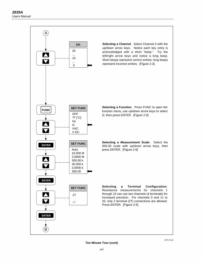
Selecting a Channel. Select Channel 0 with the up/down arrow keys. Notice each key entry is acknowledged with a short "beep." Try the left/right arrow keys and notice a long beep. Short beeps represent correct entries; long beeps represent incorrect entries. [Figure 2-3]
A
B
ENTER
ENTER
Auto10.000 M3.0000 M300.00 k30.000 k3.0000 k300.00
SET FUNC
2T
4T
SET FUNC
Selecting a Measurement Scale. Select the 300.00 scale with up/down arrow keys, then press ENTER. [Figure 2-6]
Selecting a Terminal Configuration. Resistance measurements for channels 1 through 10 can use two channels (4 terminals) for increased precision. For channels 0 and 11 to 20, only 2 terminal (2T) connections are allowed. Press ENTER. [Figure 2-6]
FUNC
ENTER
SET FUNC
OFF°F [°C]HzΩVACV DC
Selecting a Function. Press FUNC to open the function menu, use up/down arrow keys to select Ω, then press ENTER. [Figure 2-6]
op79_2f.eps
Ten Minute Tour (cont)

Ten Minute Tour (continued)
xvii
MON
0
10
MON
MON
Selecting the Monitor Mode. Press the MON key to enable monitoring. Up/down arrow keys select any configured channel for monitoring. When Channel 0 (Ω) is selected, touch the probe tips together to measure test lead resistance. Channel 10 (VAC) may have a small reading because the input is unterminated. Press MON to exit monitoring. [Figure 2-17]
B
C
SHIFT
SCAN
SCAN
SCAN
SCAN
SCAN
0
10
0
10
Selecting the SCAN Mode. Press the SCAN key to enable scanning. The display will indicate which channel is being measured during the scan. Monitor or Review can be enabled during scanning. Measurement data can be routed to the memory card, printer, or PC for display or processing. Press SCAN to exit scanning. [Figure 2-15]
Selecting the Single Scan Mode. Press the SHIFT key, release, then press the SCAN key to make a SINGLE measurement scan. [Figure 2-15]
op79_3f.eps
Ten Minute Tour (cont)

2635AUsers Manual
xviii
0:00:00
SET
INTVL
CANCL
Setting the Scan Interval. Press the INTVL key to open the interval menu. Up/down and left/right arrow keys select 0:00:00 (default) to 9:99:99. The format is HOURS:MINUTES:SECONDS. The scan interval is the total time between the start of each measurement cycle. 0:00:00 represents continuous scanning. Press CANCL to exit. [Figure 2-11]
C
D
REVIEW
SHIFT
REVIEW
CANCL
Selecting the Review Mode. Press the REVIEW key to open the Review array. The Review array holds the last, maximum, and minimum readings during all previous scans for all configured channels. Up/down arrow keys select the channel, while left/right arrow keys select LAST, MAX, and MIN. To CLEAR the Review array, press the SHIFT key, release, then press the REVIEW key. The Review array is cleared automatically by changing any parameter on any channel (including Measurement Rate). Press CANCL to exit. [Figure 2-18]
Select Channel 10. Select Channel 10 with the up/down arrow keys. [Figure 2-3]
CH
20...10... 0
REVIEW
0
10
LAST MIN MAX
op79_4f.eps
Ten Minute Tour (cont)
Ten Minute Tour (continued)
xix
CANCL
ALRM
SET ALARM
1
2
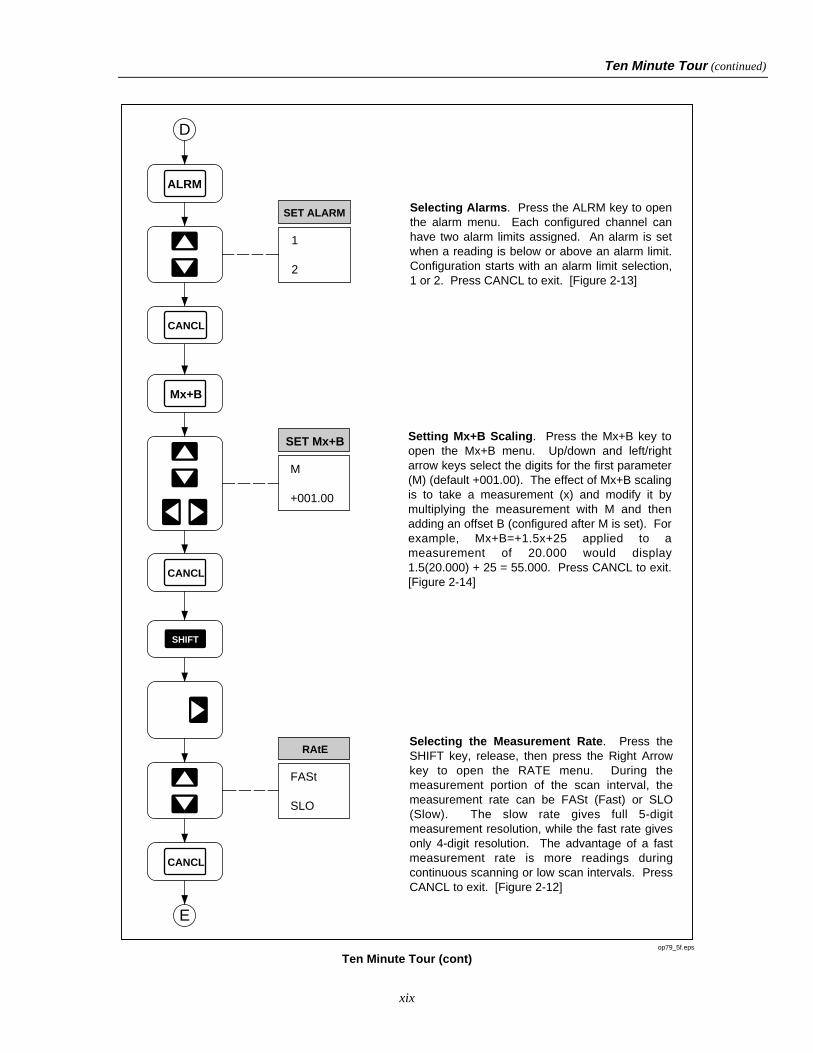
Selecting Alarms. Press the ALRM key to open the alarm menu. Each configured channel can have two alarm limits assigned. An alarm is set when a reading is below or above an alarm limit. Configuration starts with an alarm limit selection, 1 or 2. Press CANCL to exit. [Figure 2-13]
D
E
M
+001.00
SET Mx+B
Mx+B
CANCL
SHIFT
CANCL
RAtE
FASt
SLO
Setting Mx+B Scaling. Press the Mx+B key to open the Mx+B menu. Up/down and left/right arrow keys select the digits for the first parameter (M) (default +001.00). The effect of Mx+B scaling is to take a measurement (x) and modify it by multiplying the measurement with M and then adding an offset B (configured after M is set). For example, Mx+B=+1.5x+25 applied to a measurement of 20.000 would display 1.5(20.000) + 25 = 55.000. Press CANCL to exit. [Figure 2-14]
Selecting the Measurement Rate. Press the SHIFT key, release, then press the Right Arrow key to open the RATE menu. During the measurement portion of the scan interval, the measurement rate can be FASt (Fast) or SLO (Slow). The slow rate gives full 5-digit measurement resolution, while the fast rate gives only 4-digit resolution. The advantage of a fast measurement rate is more readings during continuous scanning or low scan intervals. Press CANCL to exit. [Figure 2-12]
op79_5f.eps
Ten Minute Tour (cont)

2635AUsers Manual
xx
0
totAL
TOTAL
SHIFT
TOTAL
CANCL
yEAR
94
Setting Date and Time. Press the SHIFT key, release, then press the INTVL key to open the date and time (CLOCK) menu. Up/down and left/right arrow keys select the YEAR 00 to 99. For the complete procedure, this is followed by MONTH:DAY and HOURS:MINUTES. Press CANCL to exit. [Figure 2-21]
Selecting the Totalizer Feature. Press the TOTAL key to open the totalizer display. The totalizer operates independently as a separate instrument function. Contact closures or voltage transitions between pins Σ and on the rear panel DIGITAL I/O connector are totaled and displayed by pressing the TOTAL key. To ZERO the total (already 0 in this example), press the SHIFT key, release, then press the TOTAL key again. Press CANCL to exit. [Figure 2-20]
SHIFT
INTVL
F
E
CANCL
op79_6f.eps
Ten Minute Tour (cont)

Ten Minute Tour (continued)
xxi
tRIg
ALArOnOFF
SHIFT
MON
CANCL
Selecting Triggering Options. Press the SHIFT key, release, then press the MON key to open the TRIGS option menu. A trigger option can trigger scanning, instead of using the SCAN key. OFF indicates no triggering option; ON indicates the external trigger option is active (a contact closure or voltage transition between pins TR and on the rear panel ALARM OUTPUTS connector); ALAr (Alarm) indicates scan triggering when a monitored channel goes into Alarm. Press CANCL to exit. [Figure 2-19]
CANCL
SHIFT
LIST
bAUd
38400...300
Setting the Communication Parameters. Press the SHIFT key, release, then press the LIST key to open the COMM menu. The communication parameters configure the rear-panel RS-232 interface for printer and PC operations. The first selection is bAUd (Baud) with rates from 300 to 38400 baud. For the complete procedure, this is followed by parity, flow control and echo. Press CANCL to exit. [Figure 5-2]
G
F
op79_7f.eps
Ten Minute Tour (cont)
2635AUsers Manual
xxii
dir
LASt
LISt
LIST
CANCL
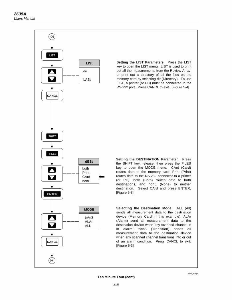
Setting the LIST Parameters. Press the LIST key to open the LIST menu. LIST is used to print out all the measurements from the Review Array, or print out a directory of all the files on the memory card by selecting dir (Directory). To use LIST, a printer (or PC) must be connected to the RS-232 port. Press CANCL to exit. [Figure 5-4]
MODE
trAnSALArALL
CANCL
Selecting the Destination Mode. ALL (All) sends all measurement data to the destination device (Memory Card in this example); ALAr (Alarm) send all measurement data to the destination device when any scanned channel is in alarm; trAnS (Transition) sends all measurement data to the destination device when any scanned channel transitions into or out of an alarm condition. Press CANCL to exit. [Figure 5-3]
dESt
bothPrintCArdnonE
SHIFT
FILES
ENTER
Setting the DESTINATION Parameter. Press the SHIFT key, release, then press the FILES key to open the MODE menu. CArd (Card) routes data to the memory card; Print (Print) routes data to the RS-232 connector to a printer (or PC); both (Both) routes data to both destinations, and nonE (None) to neither destination. Select CArd and press ENTER. [Figure 5-3]
H
G
op79_8f.eps
Ten Minute Tour (cont)
Ten Minute Tour (continued)
xxiii
FILES
InitStAtdirdAtASEtUP
CANCL
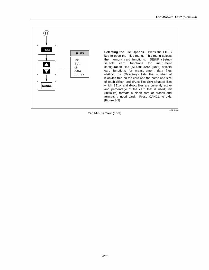
FILESSelecting the File Options. Press the FILES key to open the Files menu. This menu selects the memory card functions. SEtUP (Setup) selects card functions for instrument configuration files (SEtxx); dAtA (Data) selects card functions for measurement data files (dAtxx); dir (Directory) lists the number of kilobytes free on the card and the name and size of each SEtxx and dAtxx file; StAt (Status) lists which SEtxx and dAtxx files are currently active and percentage of the card that is used; Init (Initialize) formats a blank card or erases and formats a used card. Press CANCL to exit. [Figure 3-3]
H
op79_9f.eps
Ten Minute Tour (cont)

2635AUsers Manual
xxiv

1-1
Chapter 1Preparation for Use
Title Page
Introduction ....................................................................................................... 1-5Operating Modes ............................................................................................... 1-5
Front Panel Operation ................................................................................... 1-7Memory Card Operation ............................................................................... 1-7Computer Operation...................................................................................... 1-8Printer Operation........................................................................................... 1-8Modem Operation ......................................................................................... 1-8
Measurement Capabilities ................................................................................. 1-9Mx+B Scaling ............................................................................................... 1-9Alarms ........................................................................................................... 1-9Totalizer Channel.......................................................................................... 1-9Alarm Outputs and Digital I/O...................................................................... 1-9
Applications Software ....................................................................................... 1-9Hydra Starter Package................................................................................... 1-10Hydra Logger ................................................................................................ 1-10
Options and Accessories ................................................................................... 1-10Memory Card Reader.................................................................................... 1-10Connector Set, 2620A-100............................................................................ 1-10
Setting Up the Instrument.................................................................................. 1-11Unpacking and Inspecting the Instrument..................................................... 1-11Adjusting the Handle .................................................................................... 1-12Connecting the Instrument to a Power Source.............................................. 1-12
AC Operation............................................................................................ 1-13DC Operation............................................................................................ 1-13
Input Channels .............................................................................................. 1-13Measurement Connections ................................................................................ 1-14
Using Shielded Wiring.................................................................................. 1-14Crosstalk........................................................................................................ 1-14Universal Input Module Connections ........................................................... 1-14Alarm Outputs Connections.......................................................................... 1-17
DC Power.................................................................................................. 1-17Alarm Outputs .......................................................................................... 1-17External Trigger Input .............................................................................. 1-17
Digital I/O Connections ................................................................................ 1-18Digital I/O................................................................................................. 1-18

2635AUsers Manual
1-2
Totalizer Input .......................................................................................... 1-18Controls and Indicators ..................................................................................... 1-19
Front Panel Controls ..................................................................................... 1-19Front Panel Indicators ................................................................................... 1-19

Preparation for UseIntroduction 1
1-3

2635AUsers Manual
1-4
FUNC ALRM
Mx+B CANCEL ENTER
RATE
INTVL FILES REVIEW
SHIFT LIST TOTAL
SINGLE
TRIGS
SCAN
MON
CLOCK MODE CLEAR
LOCAL COMM ZERO
mAmVDCAC
k Hz
REVIEWLASTHYDRA SERIES II
300VMAX
COM V
M
CH
BUSY BATT
OP80F.EPS
Preparation for UseIntroduction 1
1-5
NOTEThis manual contains information and warnings that must be followed toensure safe operation and keep the instrument in safe condition.
IntroductionThe Fluke 2635A Hydra Series II Data Bucket is a 21-channel data logging instrumentthat measures and records the following electrical and physical parameters: dc volts, acvolts, resistance, frequency, and temperature. Temperature measurements are viathermocouples or resistance-temperature detectors (RTDs). Other parameters can bemeasured with an appropriate transducer, such as air pressure/vacuum (using a FlukePV350 transducer module) or DC current (using a Fluke 2600A-101 shunt resistor).When the instrument scans channels configured for measurement, readings can bedisplayed, printed out, and recorded. Virtually any analog input may be applied withoutexternal signal conditioning. The inputs for channels 1 through 20 are via a UniversalInput Module, which plugs into the rear of the unit for a quick connect/disconnectcapability. Channel 0 measurements are via the front panel input jacks using test leads(supplied). For a quick introduction to the operation of the instrument, complete the Ten-Minute Tour at the front of this manual. A summary of the Hydra Series II Data Bucketfeatures is provided in Table 1-1 and complete specifications in Appendix A. Figure 1-1shows the instrument front and rear panels.
Operating ModesThe Data Bucket may be used in a wide variety of applications using one or more of fiveoperating modes:
• Front Panel Operation
• Memory Card Operation
• Computer Operation
• Printer Operation
• Modem Operation

2635AUsers Manual
1-6
Table 1-1. Data Bucket Features
• Channel Scanning
Can be continuous scanning, scanning at an interval time, single scans, or triggered (internal orexternal) scans. Channel Monitoring may be used while scanning.
• Channel Monitoring
Make measurements on a single channel and view these measurements on the display.
• Memory Card
Store measurement data and meter configuration setup data on a removable nonvolatile RAMcard.
• Multi-Function Display
Primary display shows measurement readings; also used when setting numeric parameters.
Secondary display used for numeric entries, channel number selection and display, statusinformation, and operator prompts.
Annunciator display used to show measurement units, alarms review parameters, remote status,and configuration information.
• Front-Panel Operation
Almost all operations can be readily controlled with the front panel keys.
• Measurement Input Function and Range
Volts dc (VDC), volts ac (VAC), frequency (HZ), and resistance (e) inputs can be specified in afixed measurement range. Autoranging, which allows the instruments to use the measurementrange providing the optimum resolution, can also be selected.
• Temperature Measurement
Thermocouple types J, K, E, T, N, R, S and B, and Hoskins Engineering Co. type C are supported.Also, DIN/IEC 751 Platinum RTDs are supported.
• Totalize Events on the Totalizing Input
• Alarm Limits and Digital Output Alarm Indication
• Four-Terminal Resistance Measurements (Channels 1 through 10 only)
• RS-232 Computer Interface Operation
• Measurement Rate Selection
• Nonvolatile Memory
Storage of minimum, maximum, and most recent measurements for all scanned channels.
Storage of Computer Interface setup, channel configurations, and calibration values.
Internal storage of measurement data: storage for 100 scans of up to 21 channels, accessible onlythrough the computer interface.

Preparation for UseOperating Modes 1
1-7
COMPLIES WITHFCC-15B
+ – 0 1 2 3 TR 0 1 2 3 4 5 6 7 Σ9-16 V
DC PWR
!+30V
90-264V
50/60 Hz15VA
CAUTION FOR FIRE PROTECTION REPLACE WITH T 1/8A 250V (SLOW) FUSE
ALARM OUTPUTS DIGITAL I/O
MEETS Vfg. 243/1991
RS-232C
GNDDTR
TXRX
IEEE STD-488 PORT
SH1, AH1, T5, L4, SR1, RL1, DC1, DT1, PP0, C0, E1
IEC 664 INSTALLATIONCATEGORY II
2620A 2625A 2635AMODEL:
+ – 0 1 2 3 TR
[CTS]
[DSR]
[RTS]
0 1 2 3 4 5 6 7 Σ 67895 4 3 2 1
[2635A ONLY]
!
Ground Terminal. Connects mainframeto ground.
AC Power Connector.Connect to any line sourceof 90 to 264 VAC (50/60 Hz).
Universal Input Module.Directly wires 20 analog inputs(Channels 1 to 20) without external signal conditioning.
Alarm Outputs Connector.Outputs alarms for channels 0 to 3,DC power inputs for DC operation(9 to 16V dc), inputs external scantrigger (TR and ).
Digital I/O Connector.Outputs alarms for channels 4 to 20 (default), inputs totalizer (Σ and ).
RS-232C.Interfaces instrument with a printer, PC or modem.
op01f.eps
Figure 1-1. Data Bucket Front and Rear Panels
Front Panel OperationFront panel operations include configuration of channels in preparation for scanningoperations and simple multimeter operation by placing the instrument in the Monitormode then using the front panel jacks and test leads (channel 0) for measurements. Frontpanel operations are discussed in Chapter 2.
Memory Card OperationAn adjunct to stand-alone front panel use are operations that use the memory cardfeature. The memory card is a Static Random Access Memory (SRAM) device that plugsinto a slot on the Data Bucket front panel. An internal battery maintains the integrity ofthe stored data. An empty 256K-byte card stores 8500 scans of 4 channels, 4500 scans of10 channels, or 2500 scans of 20 channels. A typical display while scanning using thememory card is shown in Figure 1-2. The PC-compatible memory card can be used tostore measurement files and configuration files. Data extraction from the card requires a
2635AUsers Manual
1-8
personal computer (PC), where data can be sent from the Data Bucket to the PC over anRS-232 link (up to a 38,400 baud rate), or the card can be removed and taken to a PCequipped with a memory card reader (see Options and Accessories). Memory cardoperations are discussed in Chapter 3.
SCANALARM
PRN CH
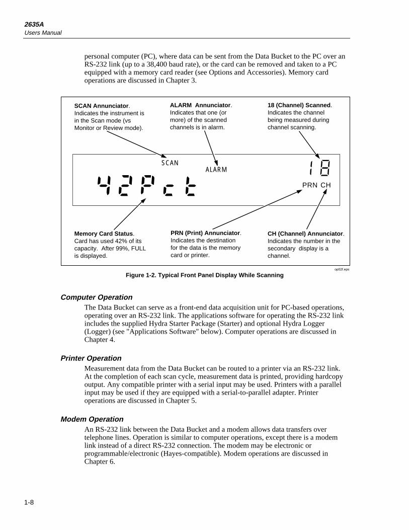
Memory Card Status. Card has used 42% of its capacity. After 99%, FULL is displayed.
PRN (Print) Annunciator. Indicates the destination for the data is the memory card or printer.
CH (Channel) Annunciator. Indicates the number in the secondary display is a channel.
18 (Channel) Scanned. Indicates the channel being measured during channel scanning.
ALARM Annunciator. Indicates that one (or more) of the scanned channels is in alarm.
SCAN Annunciator. Indicates the instrument is in the Scan mode (vs Monitor or Review mode).
op02f.eps
Figure 1-2. Typical Front Panel Display While Scanning
Computer OperationThe Data Bucket can serve as a front-end data acquisition unit for PC-based operations,operating over an RS-232 link. The applications software for operating the RS-232 linkincludes the supplied Hydra Starter Package (Starter) and optional Hydra Logger(Logger) (see "Applications Software" below). Computer operations are discussed inChapter 4.
Printer OperationMeasurement data from the Data Bucket can be routed to a printer via an RS-232 link.At the completion of each scan cycle, measurement data is printed, providing hardcopyoutput. Any compatible printer with a serial input may be used. Printers with a parallelinput may be used if they are equipped with a serial-to-parallel adapter. Printeroperations are discussed in Chapter 5.
Modem OperationAn RS-232 link between the Data Bucket and a modem allows data transfers overtelephone lines. Operation is similar to computer operations, except there is a modemlink instead of a direct RS-232 connection. The modem may be electronic orprogrammable/electronic (Hayes-compatible). Modem operations are discussed inChapter 6.
Preparation for UseMeasurement Capabilities 1
1-9
Measurement CapabilitiesBefore scanning is enabled, the Data Bucket channels are configured for measuring theselected electrical or physical parameter (volts dc, volts ac, temperature, etc.). Readingshave five digits of resolution, for example, 15.388 VAC. Scanning collects measurementdata, while the monitor mode can monitor a channel with or without scanning. Thereview mode stores the maximum, minimum and last readings. Mx+B scaling and alarmattributes can be applied to each configured channel. A totalizer channel is supplied as aseparate feature, and digital I/O functions are provided by the rear panel connectors,ALARM OUTPUTS, and DIGITAL I/O.
Mx+B ScalingThe Mx+B scaling attribute allows readings to be modified to better represent what isbeing measured. The M represents a multiplier and B represents an offset. For example,a normal reading of 3 volts can be multiplied by M=+100 and offset by B=-25, to display275 (3x100 - 25= 275). Mx+B scaling can be applied to any configured channel. Thisfeature is especially useful to scale transducer outputs for exact measurement displays.
AlarmsThe alarms attribute allows readings that rise or fall below preset levels to alert theoperator and trigger an action. For example, if you are monitoring temperature and wantto have 100ºC cause an alarm condition, this can be programmed as part of the channelconfiguration. Alarm conditions are reported as part of the measurement scan data andcan be used to trigger scanning and assert a logic low on a rear panel ALARMOUTPUTS or DIGITAL I/O connector terminal for interface with external equipment.Two alarms can be assigned to any configured channel. If Mx+B scaling is applied, thealarms are based on the scaled values.
Totalizer ChannelThe totalizer channel counts contact closures or voltage transitions. The maximum countis 65,535. The connection is at the rear panel ALARMS OUTPUTS connector, terminalsSUM and GROUND. The Data Bucket continuously samples the totalizer input on therear panel, independently from Hydra's scanning and other activities.
Alarm Outputs and Digital I/OAlarm outputs are available on the rear panel ALARM OUTPUTS and DIGITAL I/Oconnectors. The four ALARM OUTPUT lines are permanently assigned to signal alarmsfor channels 0, 1, 2, and 3. The eight DIGITAL I/O lines can be used to signal alarmconditions for channels 4 to 20. All input/output lines are transistor-transistor-logic(TTL) compatible. For operations that do not use a computer interface, these are the onlyfunctions of the ALARM OUTPUTS and DIGITAL I/O connections. When a computerinterface is used, the DIGITAL I/O lines can be assigned in the applications software fora variety of inputs or outputs. The ALARM OUTPUTS can also be assigned for I/Ooperations if the dedicated alarm function is not used (which has priority).
Applications SoftwarePC applications software Hydra Starter (supplied) and Hydra Logger Package (Logger)(optional) operate the instrument via the RS-232 computer interface. The softwarepackages are described in separate technical manuals; however, each is summarizedbelow.
2635AUsers Manual
1-10
An extensive command set allows the user to develop custom software in GWBASIC,QBASIC, and QuickC. The command set is discussed in Chapter 4.
Hydra Starter PackageStarter is a DOS based, menu-driven software package used to transfer configurationdata from and to the instrument, log measurement data collected by the instrument,extract data from the memory card, and manage the acquired data. During operation,Starter displays readings of all channels in real time and can automatically log the data toa Lotus 1-2-3 compatible file.
Hydra LoggerHydra Logger (model 2635A-901) is an optional Windows-based package that allowscomplete setup, data collection and data conversion from up to two Hydra units. Loggercommunicates over the RS-232 port on a personal computer and may be used withtelephone models. Hydra Logger with Trending (model 2635A-902) includes acomprehensive trending package that simulates a chart recorder. A brochure withcomplete details is available.
Options and AccessoriesOptions and accessories include measurement transducers, cables, applications software,carrying case and other items, all of which are summarized in Table 1-2.
Memory Card ReaderData Bucket measurement data and configuration setups may be stored on a memorycard that is inserted into the slot on the instrument front panel (see Figure 1-1). Toreview and analyze the recorded data, the memory card data can be routed to a PC viathe RS-232 interface, or the memory card can be removed and taken to a PC equippedwith a memory card reader. The memory card reader (optional) is external to the PC andconnects to a PC parallel port (LPT1, LPT2, etc.). The memory card reader is configuredas another PC drive, e.g., the D: drive. Memory card files include data files(dAtxx.HYD) and configuration setups (SEtxx.HYD). The PC manipulates these filesusing applications software Starter (supplied) and Logger (optional). The selectedmemory card reader must read SRAM cards and meet Personal Computer Memory CardInternational Association (PCMCIA)/Japan Electronics Industrial DevelopmentAssociation (JEIDA) standards. This memory card application meets PCMCIA standardsrelease 2.0.
Connector Set, 2620A-100The 2620A-100 is a complete set of input connectors: one Universal Input Module, oneALARM OUTPUTS connector, and one DIGITAL I/O connector. The use of additionalconnector sets allows quick equipment interface to several wiring setups.
Preparation for UseSetting Up the Instrument 1
1-11
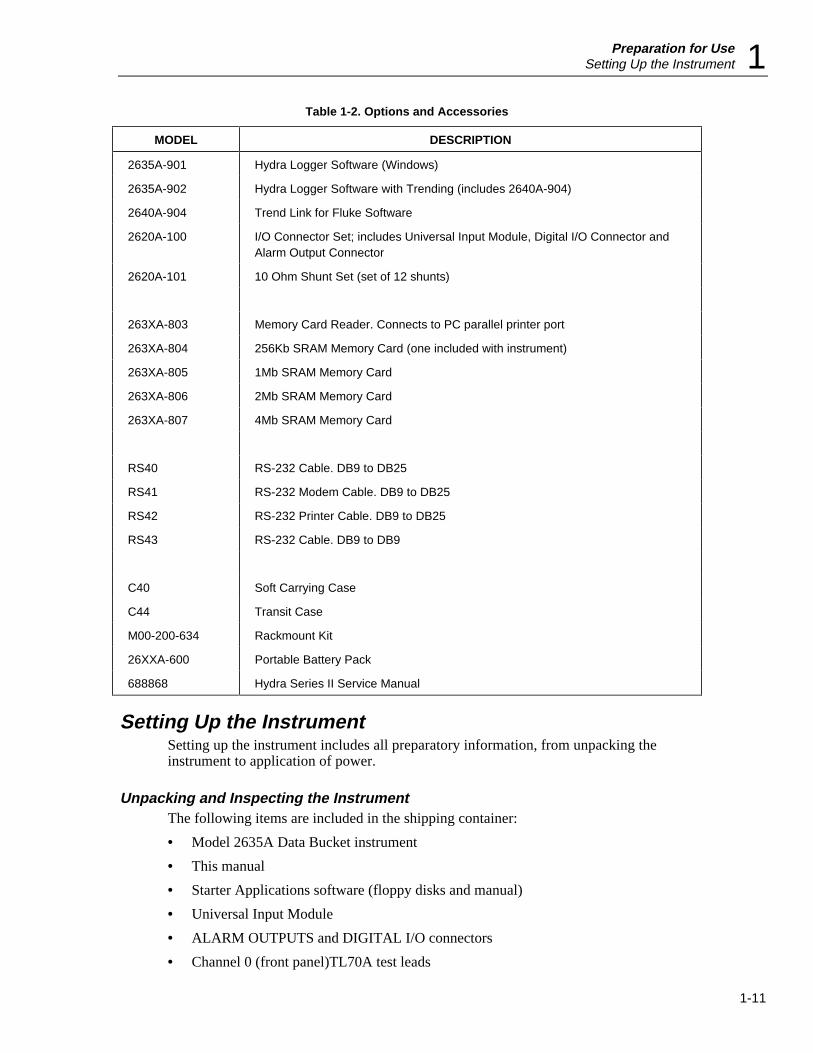
Table 1-2. Options and Accessories
MODEL DESCRIPTION
2635A-901 Hydra Logger Software (Windows)
2635A-902 Hydra Logger Software with Trending (includes 2640A-904)
2640A-904 Trend Link for Fluke Software
2620A-100 I/O Connector Set; includes Universal Input Module, Digital I/O Connector andAlarm Output Connector
2620A-101 10 Ohm Shunt Set (set of 12 shunts)
263XA-803 Memory Card Reader. Connects to PC parallel printer port
263XA-804 256Kb SRAM Memory Card (one included with instrument)
263XA-805 1Mb SRAM Memory Card
263XA-806 2Mb SRAM Memory Card
263XA-807 4Mb SRAM Memory Card
RS40 RS-232 Cable. DB9 to DB25
RS41 RS-232 Modem Cable. DB9 to DB25
RS42 RS-232 Printer Cable. DB9 to DB25
RS43 RS-232 Cable. DB9 to DB9
C40 Soft Carrying Case
C44 Transit Case
M00-200-634 Rackmount Kit
26XXA-600 Portable Battery Pack
688868 Hydra Series II Service Manual
Setting Up the InstrumentSetting up the instrument includes all preparatory information, from unpacking theinstrument to application of power.
Unpacking and Inspecting the InstrumentThe following items are included in the shipping container:
• Model 2635A Data Bucket instrument
• This manual
• Starter Applications software (floppy disks and manual)
• Universal Input Module
• ALARM OUTPUTS and DIGITAL I/O connectors
• Channel 0 (front panel)TL70A test leads

2635AUsers Manual
1-12
• Line power cord
• Type "T" Thermocouple
• 256K-byte Memory Card
Carefully remove the instrument from its shipping container and inspect the instrumentfor possible damage or missing items. If the instrument is damaged or anything ismissing, contact the place of purchase immediately. Save the container and packingmaterial in case you have to return the instrument.
Rotate the rear feet of the instrument 180 degrees so that their support pads extendslightly below the bottom of the case.
Adjusting the HandleThe handle can be positioned to four angles: one for carrying, two for viewing, and onefor handle removal. To change the angle, simultaneously pull both handle ends outwardto hard stops (about 1/4-inch on each side) and then rotate the handle to one of the fourstop positions shown in Figure 1-3. With the handle in the straight-up removal position,you can disengage and free one handle side at a time.
3. Carrying Position
1. Viewing Position 2. Alternative Viewing Position
4. Removal Position (to Remove, Pull Ends Out)
Pull One End Out and Towards You.Then Pull the Other End Out.
V
300VMAX
COM Ω
op03f.eps
Figure 1-3. Adjusting the Handle
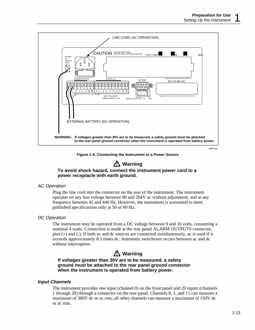
Connecting the Instrument to a Power SourceThe instrument can be connected to an ac or dc source. Connections are shown in Figure1-4 and described below.
Preparation for UseSetting Up the Instrument 1
1-13
COMPLIES WITHFCC-15B
+ – 0 1 2 3 TR 0 1 2 3 4 5 6 7 Σ9-16 V
DC PWR
!+30V
90-264V
50/60 Hz15VA
CAUTION FOR FIRE PROTECTION REPLACE WITH T 1/8A 250V (SLOW) FUSE
ALARM OUTPUTS DIGITAL I/O
MEETS Vfg. 243/1991
RS-232C
GNDDTR
TXRX
IEEE STD-488 PORT
SH1, AH1, T5, L4, SR1, RL1, DC1, DT1, PP0, C0, E1
IEC 664 INSTALLATIONCATEGORY II
2620A 2625A 2635AMODEL:
+ – 0 1 2 3 TR
[CTS]
[DSR]
[RTS]
0 1 2 3 4 5 6 7 Σ 67895 4 3 2 1
[2635A ONLY]
!
EXTERNAL BATTERY (DC OPERATION)
WARNING: If voltages greater than 30V are to be measured, a safety ground must be attached to the rear panel ground connector when the instrument is operated from battery power.
LINE CORD (AC OPERATION)
op04f.eps
Figure 1-4. Connecting the Instrument to a Power Source
WarningTo avoid shock hazard, connect the instrument power cord to apower receptacle with earth ground.
AC OperationPlug the line cord into the connector on the rear of the instrument. The instrumentoperates on any line voltage between 90 and 264V ac without adjustment, and at anyfrequency between 45 and 440 Hz. However, the instrument is warranted to meetpublished specifications only at 50 or 60 Hz.
DC OperationThe instrument may be operated from a DC voltage between 9 and 16 volts, consuming anominal 4 watts. Connection is made at the rear panel ALARM OUTPUTS connector,pins (+) and (-). If both ac and dc sources are connected simultaneously, ac is used if itexceeds approximately 8.3 times dc. Automatic switchover occurs between ac and dcwithout interruption.
WarningIf voltages greater than 30V are to be measured, a safetyground must be attached to the rear panel ground connectorwhen the instrument is operated from battery power.
Input ChannelsThe instrument provides one input (channel 0) on the front panel and 20 inputs (channels1 through 20) through a connector on the rear panel. Channels 0, 1, and 11 can measure amaximum of 300V dc or ac rms; all other channels can measure a maximum of 150V dcor ac rms.
2635AUsers Manual
1-14
CautionDo not exceed the specified input voltage levels or equipmentdamage could result.
Measurement ConnectionsW Warning
To avoid electric shock:
• When the input module is installed, consider all channelswith connections as accessible terminals that may behazardous live.
• Disconnect the input module before touching or changingexternal wiring.
Input connections include the front panel terminals (channel 0), rear panel connectionsusing the Universal Input Module (channels 1 through 20), and I/O functions using theALARM OUTPUTS and DIGITAL I/O connectors. The instrument is protected fromchannel configuration errors. For example, accidentally applying 300V ac to a channelconfigured for resistance measurements will not damage the instrument.
Using Shielded WiringShielded wires and sensors (such as thermocouples) should be used in environmentswhere "noisy" voltage sources are present. When shielded wiring is used, the shield isnormally connected to the L (low) input terminals for each channel. Alternateconfigurations should be examined for each equipment application.
CrosstalkThe instrument allows the mixing of various types of measurement. A phenomenonknown as crosstalk can cause one signal to interfere with another and thereby introducemeasurement errors. To reduce the effects of crosstalk in making measurementconnections, do the following:
• Keep any input wiring carrying ac volts signals physically separate from the inputwiring of other sensitive channels.
• Avoid connecting inputs with ac volts signals adjacent to sensitive channel inputs.Leave unconnected channels between the inputs, if possible.
• Avoid connecting inputs with ac volts signals to any channel 10 numbers away froma sensitive channel (i.e., 4-terminal input channels).
• Avoid tying L (low) or (especially) H (high) inputs of a sensitive channel to earth(chassis) ground. This is very important in resistance measurements.
• Avoid high-source impedances on sensitive channels, or minimize the capacitance ofthe sensitive channel to earth (chassis) ground for high impedance inputs.
• Whenever high ohms measurements (>10 kΩ) must be made accurately, avoidconnecting any inputs carrying ac volts signals.
Measurement errors introduced by crosstalk are discussed in Appendix B.
Universal Input Module ConnectionsFor channels 1 through 20, use the H (high) and L (low) inputs on the rear panelUniversal Input Module, as shown in Figure 1-5. Perform the following procedure tomake connections to the Universal Input Module:

Preparation for UseMeasurement Connections 1
1-15
LH
L
HL
H
HL
HL
HL
HL
HL
HL
HL
HL
L
HL
H
HL
HL
HL
HL
HL
HL
HL
HL
H L H L H L H L H L H L H L H L H L
H L H L H L H L H L H L H L H L H L H L
STRAIN RELIEF
1
11
2
12
3
13
4
14
5
15
6
16
7
17
8
18
9
19
10
20
op05f.eps
Figure 1-5. Universal Input Module Connections
WarningInputs may be connected to live voltages. To avoid electricshock, remove inputs from live voltages before opening thismodule.
1. Remove the module from the rear panel by pressing the release tab on the bottom ofthe module and then pulling the module out of its connector.
2. Loosen the two large screws on top and open the module
3. Connect the wires to H (high) and L (low) for each channel.
4. Thread these wires through the strain-relief pins and out the back of the module.
5. Close the module cover, secure the screws, and insert the module in the connector atthe rear of the instrument until it latches in place.
NoteChannel 0 on the front panel does not support thermocouplemeasurements.
Resistance and RTD measurements can be made with two terminals (one channel) orfour terminals (two channels). The four-terminal connection provides increased accuracy(nominal 1%) over the two-terminal connection. Refer to Figure 1-6.
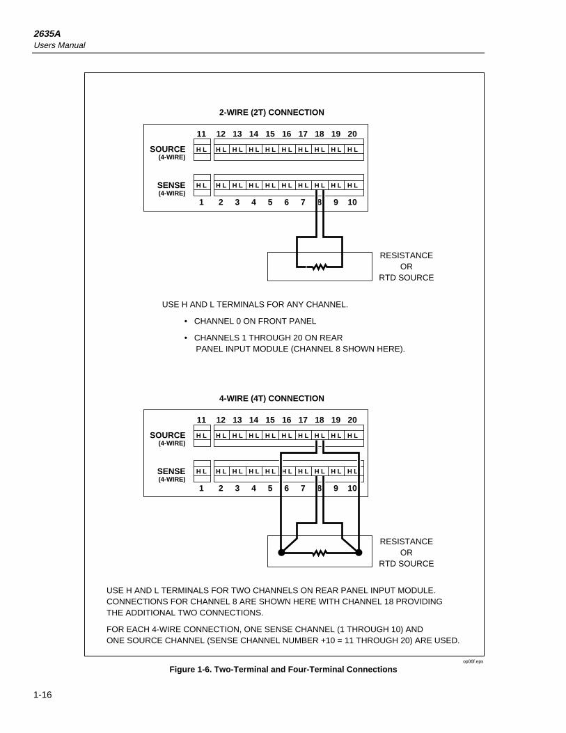
2635AUsers Manual
1-16
1211 13 14 15 16 17 18 19 20
21 3 4 5 6 7 8 9 10
SOURCE(4-WIRE)
SENSE(4-WIRE)
H L H L H L H L H L H L H L H L H L H L
H L H L H L H L H L H L H L H L H L H L
2-WIRE (2T) CONNECTION
RESISTANCEOR
RTD SOURCE
USE H AND L TERMINALS FOR ANY CHANNEL.
• CHANNEL 0 ON FRONT PANEL
• CHANNELS 1 THROUGH 20 ON REAR PANEL INPUT MODULE (CHANNEL 8 SHOWN HERE).
1211 13 14 15 16 17 18 19 20
21 3 4 5 6 7 8 9 10
SOURCE(4-WIRE)
SENSE(4-WIRE)
H L H L H L H L H L H L H L H L H L H L
H L H L H L H L H L H L H L H L H L H L
4-WIRE (4T) CONNECTION
RESISTANCEOR
RTD SOURCE
USE H AND L TERMINALS FOR TWO CHANNELS ON REAR PANEL INPUT MODULE. CONNECTIONS FOR CHANNEL 8 ARE SHOWN HERE WITH CHANNEL 18 PROVIDING THE ADDITIONAL TWO CONNECTIONS.
FOR EACH 4-WIRE CONNECTION, ONE SENSE CHANNEL (1 THROUGH 10) AND ONE SOURCE CHANNEL (SENSE CHANNEL NUMBER +10 = 11 THROUGH 20) ARE USED.
op06f.eps
Figure 1-6. Two-Terminal and Four-Terminal Connections
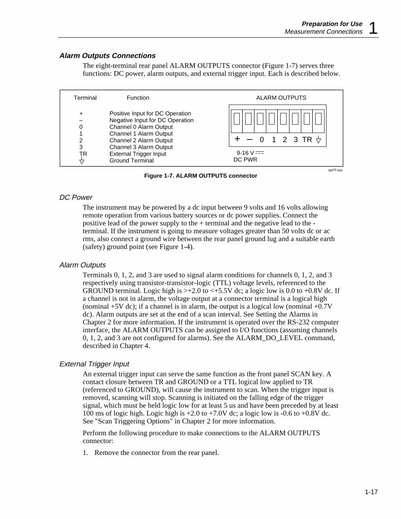
Preparation for UseMeasurement Connections 1
1-17
Alarm Outputs ConnectionsThe eight-terminal rear panel ALARM OUTPUTS connector (Figure 1-7) serves threefunctions: DC power, alarm outputs, and external trigger input. Each is described below.
9-16 VDC PWR
ALARM OUTPUTS
+ – 0 1 2 3 TR
Terminal
+–0123TR
Function
Positive Input for DC OperationNegative Input for DC OperationChannel 0 Alarm OutputChannel 1 Alarm OutputChannel 2 Alarm OutputChannel 3 Alarm OutputExternal Trigger InputGround Terminal
op07f.eps
Figure 1-7. ALARM OUTPUTS connector
DC PowerThe instrument may be powered by a dc input between 9 volts and 16 volts allowingremote operation from various battery sources or dc power supplies. Connect thepositive lead of the power supply to the + terminal and the negative lead to the -terminal. If the instrument is going to measure voltages greater than 50 volts dc or acrms, also connect a ground wire between the rear panel ground lug and a suitable earth(safety) ground point (see Figure 1-4).
Alarm OutputsTerminals 0, 1, 2, and 3 are used to signal alarm conditions for channels 0, 1, 2, and 3respectively using transistor-transistor-logic (TTL) voltage levels, referenced to theGROUND terminal. Logic high is >+2.0 to <+5.5V dc; a logic low is 0.0 to +0.8V dc. Ifa channel is not in alarm, the voltage output at a connector terminal is a logical high(nominal +5V dc); if a channel is in alarm, the output is a logical low (nominal +0.7Vdc). Alarm outputs are set at the end of a scan interval. See Setting the Alarms inChapter 2 for more information. If the instrument is operated over the RS-232 computerinterface, the ALARM OUTPUTS can be assigned to I/O functions (assuming channels0, 1, 2, and 3 are not configured for alarms). See the ALARM_DO_LEVEL command,described in Chapter 4.
External Trigger InputAn external trigger input can serve the same function as the front panel SCAN key. Acontact closure between TR and GROUND or a TTL logical low applied to TR(referenced to GROUND), will cause the instrument to scan. When the trigger input isremoved, scanning will stop. Scanning is initiated on the falling edge of the triggersignal, which must be held logic low for at least 5 us and have been preceded by at least100 ms of logic high. Logic high is +2.0 to +7.0V dc; a logic low is -0.6 to +0.8V dc.See "Scan Triggering Options" in Chapter 2 for more information.
Perform the following procedure to make connections to the ALARM OUTPUTSconnector:
1. Remove the connector from the rear panel.
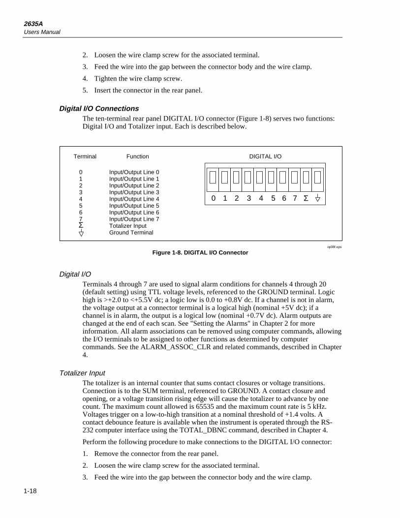
2635AUsers Manual
1-18
2. Loosen the wire clamp screw for the associated terminal.
3. Feed the wire into the gap between the connector body and the wire clamp.
4. Tighten the wire clamp screw.
5. Insert the connector in the rear panel.
Digital I/O ConnectionsThe ten-terminal rear panel DIGITAL I/O connector (Figure 1-8) serves two functions:Digital I/O and Totalizer input. Each is described below.
DIGITAL I/O
2 3 4 5 6 7
Terminal
01234567
Function
Input/Output Line 0Input/Output Line 1Input/Output Line 2Input/Output Line 3Input/Output Line 4Input/Output Line 5Input/Output Line 6Input/Output Line 7Totalizer InputGround Terminal
10 Σ
Σ
op08f.eps
Figure 1-8. DIGITAL I/O Connector
Digital I/OTerminals 4 through 7 are used to signal alarm conditions for channels 4 through 20(default setting) using TTL voltage levels, referenced to the GROUND terminal. Logichigh is >+2.0 to <+5.5V dc; a logic low is 0.0 to +0.8V dc. If a channel is not in alarm,the voltage output at a connector terminal is a logical high (nominal +5V dc); if achannel is in alarm, the output is a logical low (nominal +0.7V dc). Alarm outputs arechanged at the end of each scan. See "Setting the Alarms" in Chapter 2 for moreinformation. All alarm associations can be removed using computer commands, allowingthe I/O terminals to be assigned to other functions as determined by computercommands. See the ALARM_ASSOC_CLR and related commands, described in Chapter4.
Totalizer InputThe totalizer is an internal counter that sums contact closures or voltage transitions.Connection is to the SUM terminal, referenced to GROUND. A contact closure andopening, or a voltage transition rising edge will cause the totalizer to advance by onecount. The maximum count allowed is 65535 and the maximum count rate is 5 kHz.Voltages trigger on a low-to-high transition at a nominal threshold of +1.4 volts. Acontact debounce feature is available when the instrument is operated through the RS-232 computer interface using the TOTAL_DBNC command, described in Chapter 4.
Perform the following procedure to make connections to the DIGITAL I/O connector:
1. Remove the connector from the rear panel.
2. Loosen the wire clamp screw for the associated terminal.
3. Feed the wire into the gap between the connector body and the wire clamp.
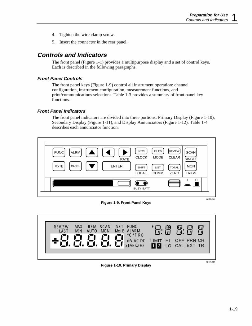
Preparation for UseControls and Indicators 1
1-19
4. Tighten the wire clamp screw.
5. Insert the connector in the rear panel.
Controls and IndicatorsThe front panel (Figure 1-1) provides a multipurpose display and a set of control keys.Each is described in the following paragraphs.
Front Panel ControlsThe front panel keys (Figure 1-9) control all instrument operation: channelconfiguration, instrument configuration, measurement functions, andprint/communications selections. Table 1-3 provides a summary of front panel keyfunctions.
Front Panel IndicatorsThe front panel indicators are divided into three portions: Primary Display (Figure 1-10),Secondary Display (Figure 1-11), and Display Annunciators (Figure 1-12). Table 1-4describes each annunciator function.
CLOCK CLEAR
LOCAL COMM ZERO
RATE MODE SINGLE
TRIGS
FUNC ALRM INTVL FILES REVIEW SCAN
CANCL ENTER SHIFT LIST TOTAL MONMx B+
BUSY BATT
op09f.eps
Figure 1-9. Front Panel Keys
REVIEWLAST
MAXMIN
REMAUTO
SCANMON
x1MkLIMIT HI
LOOFFCAL
PRNEXT
SETMx+B
FUNCALARM°C °F ROmV AC DC
HzCHTR1 2Ω
F
op10f.eps
Figure 1-10. Primary Display

2635AUsers Manual
1-20
REVIEWLAST
MAXMIN
REMAUTO
SCANMON
SETMx+B
FUNCALARM°C °F ROmV AC DC
x1Mk HzLIMIT HI
LOOFFCAL
PRNEXT
CHTR1 2Ω
F
op11f.eps
Figure 1-11. Secondary Display
REVIEWLAST
MAXMIN
REMAUTO
SCANMON
SETMx+B
FUNCALARM°C °F ROmV AC DC
x1Mk HzHILO
OFFCAL
PRNEXT
CHTRΩ
F
LIMIT1 2
op12f.eps
Figure 1-12. Annunciator Display

Preparation for UseControls and Indicators 1
1-21
Table 1-3. Front Panel Keys Description
Key Description
F Calls up the menu to set the function for the channel
A Calls up the menu to set alarm limits S and T for the channel.
B Calls up the menu to set scaling on the channel.
C Used to exit any setup menu and return to Inactive Mode, without savingsettings you’ve selected thus far. Exceptions exist under the following twoconditions
If you cancel out of the alarm menu part way through defining alarm limit T, anyjust-made entries for alarm limit S will still take effect.
If you cancel out of the Mx+B menu part way through defining the B value, anyjust-made entries for the M value will still take effect.
This key also provides a handy way to remove the Totalizer value or Reviewdata from the display.
G D Used to change the channel number and to step through choices in any of thesetup menus. These arrow keys have an automatic repeat action when helddown for more than 1 second.
J H Used to step through choices in several of the setup menus. These arrow keyshave an automatic repeat action when held down for more than 1 second.
E Used to accept a selection just made in any setup menu.
I Allows you to change the scan interval. Scanning becomes continuous whenthe interval is set to 0:00:00.
P Accesses menus related to memory card operation, including status, directory,and manipulation of all SEtxx and dAtxx files.
N Calls up the Review array of MIN, MAX and LAST values to the display.
K Accesses secondary functions under various keys, as described below. Whenthis key is pressed, "SHIFt" appears on the right display, but automaticallydisappears if you have not made a selection within 5 seconds or press C.
L Prints out the Last values of the Review array or contents of the memory carddirectory via the RS-232 computer interface.
O Calls up the present Totalizer count to the display.
Q Turns the Scan function on or off.
Triggers a single scan when the instrument is under remote control withoutlockout (REMS).
M Turns the Monitor function on or off
RATE K J Allows you to change the scanning speed: “Slo” for highest accuracy, or “FASt”for highest throughput
CLOCK K I Allows you to set the internal day/date clock
MODE K P Allows you to select the destination and conditions for which scanmeasurements will be automatically printed or logged.

2635AUsers Manual
1-22
Table 1-3. Front Panel Keys Description (cont.)
Key Description
CLEARK N
This key sequence clears the entire contents of the Review array. Review datamust be presently shown on the display to clear the array.
LOCAL K When under remote control without lockout (REMS), this returns control to thefront panel.
COMM K L Allows you to set up the computer interface port.
ZEROK O
While the Totalizer count is displayed, resets the Totalizer to 0.
SINGLE K Q Forces an immediate scan of all defined channels. If a scan is presently inprogress, this new request is ignored. Once begun, the full scan is completed.Configuration changes are not allowed while a scan is in progress.
Table 1-4. Annunciator Descriptions
Annunciator Description
MON Indicates that the Monitor function is enabled.
SCAN Indicates that the Scan function is enabled. Scanning can be enabled as a single scan(K Q), with a scan interval, with an alarm-trigger or with an external trigger.
CH Indicates that the channel number is displayed immediately above, in the right display.
SET Lit when the instrument is in Configuration Mode.
Mx+B Lit while Mx+B scaling is being defined and when a measurement on the display hasbeen scaled with an M value other than 1 and/or a B value other than 0 has beendefined for this channel.
FUNC Lit when a measurement function is being defined for this channel.
ALARM Lit when alarm values are being defined for this channel or when an alarm limit hasbeen exceeded while measuring.
v Indicates that the measurement function is volts for this channel (used with the AC orDC annunciator).
DC Indicates that the measurement function is dc voltage for this channel.
AC Indicates that the measurement function is ac voltage for this channel.
e Indicates that the measurement function is resistance for this channel.
Hz Indicates that the measurement function is frequency for this channel.
°C Indicates that the measurement function is temperature for this channel and that thedegree unit is Celsius.
°F Indicates that the measurement function is temperature for this channel and that thedegree unit is Fahrenheit.
m (milli) a multiplier for the displayed value, e.g., mV for millivolts. Also used when definingalarm and Mx+B values.
x1 (times 1) a multiplier for the displayed value. Used when defining alarm and Mx+Bvalues.
k (kilo) a multiplier for the displayed value, e.g., kHz for kilohertz. Also used when definingalarm and Mx+B values.

Preparation for UseControls and Indicators 1
1-23
Table 1-4. Annunciator Descriptions (cont)
Annunciator Description
M (mega) a multiplier for the displayed value, e.g., M½ for megohms. Also used whendefining alarm and Mx+B values.
R0 Lit when the ice point resistance is being defined for RTD measurements on thedisplayed channel.
OFF Indicates there is no measurement function defined for the displayed channel; OFFchannels are skipped over when scanning. OFF is also used when defining an alarmvalue to indicate that the alarm limit is to be ignored.
AUTO Indicates that autoranging is enabled for the displayed channel.
LIMIT Used with the [1] and [2] annunciators when you are setting an alarm limit value. Also litwhen displaying a measurement value (LAST, Monitor) which has exceeded an alarmlimit.
1 Lit when alarm limit 1 is being defined. Also lit when displaying a measurement value(LAST, Monitor) which has exceeded alarm limit 1.
2 Lit when alarm limit 2 is being defined. Also lit when displaying a measurement value(LAST, Monitor) which has exceeded alarm limit 2.
HI, LO Identifies alarm limit sensing (high or low) during channel configuration. At other times,identifies an alarm condition.
REVIEW Indicates that review data is being displayed (used in conjunction with the MIN, MAX,and LAST annunciators).
MIN, MAX Indicates that the displayed value is the minimum (maximum) value measured on thischannel.
LAST Indicates that the displayed value is the most recent scan measurement taken on thischannel.
PRN Indicates that the autoprint function is enabled (to send readings to a printer or PC) orthe memory storage function is on (to store readings in a memory card).
EXT Indicates that external triggering (on the rear panel) is enabled.
TR Indicates that internal triggering (from the monitor alarm) is enabled. Also used with EXTwhen external triggering is enabled.
REM Indicates that the instrument is under the control of the RS-232 computer interface(bright) or a front panel lockout option has been enabled (dim).
CAL Indicates that the instrument's internal calibration constants have been corrupted.
F (Not Used)

2635AUsers Manual
1-24

2-1
Chapter 2Front Panel Operations
Title Page
Summary of Front Panel Operations ................................................................. 2-5Configuring the Instrument for Operation......................................................... 2-6
Turning the Power on.................................................................................... 2-6Selecting a Channel....................................................................................... 2-8
Configuring a Measurement Channel................................................................ 2-8Configuring a Channel to Measure DC Volts............................................... 2-9Configuring a Channel to Measure AC Volts............................................... 2-10Configuring a Channel to Measure Resistance............................................. 2-11Configuring a Channel to Measure Frequency ............................................. 2-12Configuring a Channel to Measure Temperature.......................................... 2-13
Thermocouples ......................................................................................... 2-13Resistance-Temperature Detectors ........................................................... 2-13Thermocouple Restrictions:...................................................................... 2-13Resistance Temperature Detectors Restrictions: ...................................... 2-13
Configuring a Channel Off ........................................................................... 2-16Setting Operating Conditions ............................................................................ 2-16
Setting the Scan Interval ............................................................................... 2-17Setting the Measurement Rate ...................................................................... 2-18Setting the Alarms......................................................................................... 2-18
Alarm Indications While Scanning........................................................... 2-18Alarm Indications While Monitoring ....................................................... 2-19Alarm Indications While Reviewing ........................................................ 2-19Clearing Alarm Parameters from a Channel............................................. 2-19Alarm Outputs for Channel 0 to 3 Using the Alarm Outputs Connector . 2-19Alarm Outputs for Channels 4 to 20 Using the Digital I/O Connector .... 2-19Alarms and Autoprinting .......................................................................... 2-20Alarms and Monitor-Alarm Triggering .................................................... 2-20Alarms and Mx+B Scaling ....................................................................... 2-20
Setting the Mx+B Scaling............................................................................. 2-23Examples................................................................................................... 2-23Restrictions ............................................................................................... 2-23Clearing Mx+B Scaling from a Channel .................................................. 2-23
Operating Modes ............................................................................................... 2-26Using the Scan Mode .................................................................................... 2-26
Memory Card as a Data Destination......................................................... 2-26

2635AUsers Manual
2-2
Memory Card Formatting ......................................................................... 2-26Memory Card Capacity............................................................................. 2-26Memory Card Files ................................................................................... 2-26Memory Card Exchange During Scanning............................................... 2-26Memory Card Data Extraction.................................................................. 2-27
Memory Card Error Messages ...................................................................... 2-28Using the Monitor Mode............................................................................... 2-29Using the Review Mode................................................................................ 2-30
Additional Features ........................................................................................... 2-31Scan Triggering Options ............................................................................... 2-31
External Trigger........................................................................................ 2-31Monitor-Alarm Trigger............................................................................. 2-31Triggering Options and Memory Card Operation .................................... 2-31
Totalizer Operation ....................................................................................... 2-32Digital Input/output Lines............................................................................. 2-33Setting Date and Time................................................................................... 2-34Reading Instrument Software Versions ........................................................ 2-35Returning to the Local Mode ........................................................................ 2-35Front Panel Key Lockout Options ................................................................ 2-36
Instrument Interfaces ......................................................................................... 2-36Memory Card Interface ................................................................................. 2-36RS-232 Computer Interface .......................................................................... 2-37Using the RS-232 Computer Interface With a Printer .................................. 2-37Using the RS-232 Computer Interface With a Modem................................. 2-37

Front Panel OperationsSummary of Front Panel Operations 2
2-3

2635AUsers Manual
2-4
HYDRA DATA BUCKET
300VMAX
COM V
FUNC ALRM
Mx+B CANCEL ENTER
RATE
INTVL FILES REVIEW
SHIFT LIST TOTAL
SINGLE
TRIGS
SCAN
MON
CLOCK MODE CLEAR
LOCAL COMM ZERO
mAmVDCAC
k Hz
REVIEWLAST
CH
BUSY BATT
op92f.eps

Front Panel OperationsSummary of Front Panel Operations 2
2-5
Summary of Front Panel OperationsDescriptions of all equipment operations start at the front panel and proceed through thefollowing topics, which appear in the following sequence:
• Preparing for Operation• Configuring a Measurement Channel• Setting Operating Conditions• Operating Modes• Additional Features• Instrument Interfaces
This chapter applies exclusively to instrument applications that use only the front panelcontrols and annunciators. Other chapters apply specifically to applications that use thememory card feature or interface with a computer, printer, or modem. It is assumed thatthe user has understood the information in Chapter 1, "Preparation for Use," includingsuch topics as setting up the instrument and making measurement connections. Performthe Ten-Minute Tour at the front of this manual for a quick overview of instrumentoperation.
All the procedures in this chapter use control/annunciator diagrams that provide thecontrol sequences and expected indicators for each operation. A summary of how to usethe control/annunciator diagrams is shown in Figure 2-1.
FUNC
ENTER
SET FUNC
OFF°FHzΩVACV DC
ENTER
SET FUNC
Typical
Required
The shaded portion above a menu indicates a front panel display for that menu. In this example, the menu is called SET FUNC.
A solid pointer means the menu selection is required. In this example, °F must be selected.
A dotted arrow means the menu selection is typical and the user must choose the item that meets the instrument application. In this example, a typical choice is thermocouple T.
A procedure that includes an audible "beep" will use a beep symbol as shown.
Press then release the front panel key shown. In this example, press the FUNC key
Use the up/down arrow keys to select an item from the displayed menu.
When the menu item selected with the up/down arrow keys is correct, press the ENTER key.
When there are multiple selections, the procedure will continue.
A dotted pointer indicates a typical menu selection, while a solid pointer indicates a required selection.
= "Beep"
JKETNRSbCPt
op13f.eps
Figure 2-1. How to use the Control/Annunciator Diagrams

2635AUsers Manual
2-6
Configuring the Instrument for OperationTo prepare the equipment for front panel operations, perform the two followingprocedures:
• Turning the Power On (Figure 2-2)
• Selecting a Channel (Figure 2-3)
Turning the Power onThere are four power-on options. Figure 2-2 describes the control sequences for eachoption.
Each power-on sequence includes a four-second selftest routine that lights the frontpanel display. If the selftest fails, the instrument will beep and display ERROR plus analphanumeric error code character (see Table 2-2). If there is more than one error, eachis displayed in sequence at two-second intervals. Refer to the maintenance informationin Chapter 7 for guidance on what to do when an error is detected.
POWER (Selftest)
Error
POWER
CANCL
+
Simple Power-On. Press the POWER switch. After selftest, the display clears and the instrument resumes whatever operation was in effect when power was last removed.
Configuration-Reset Power-On. Hold down the CANCL key and press the POWER switch. Hold the CANCL key until the instrument completes selftest and "beeps" in acknowledgement. All channel configuration data is erased and the operating parameters are set to default settings (see Table 2-1). The temperature scale and communication settings are not affected.
Display-Hold Power-On. Hold down the SHIFT key and press the POWER switch. Hold the SHIFT key until the instrument completes the selftest routine and "beeps" in acknowledgement. The front panel display will remain lit until any key is pressed.
Temperature-Toggle Power-On. Hold down the Mx+B key and press the POWER switch. Hold the Mx+B key until the instrument completes selftest, "beeps" in acknowledgement, displaying either °F or °C. To select the other temperature scale, remove power and repeat the procedure.
(Selftest)
Error
POWER
SHIFT
+
(Selftest)
Error
POWER
Mx+B
+
(Selftest)
Error
op14f.eps
Figure 2-2. Turning the Power On

Front Panel OperationsConfiguring the Instrument for Operation 2
2-7
Table 2-1. Configuration Reset (Default) Settings
Parameter Default Setting
Channels 0 to 20 Off
Measurement Rate Slow
Mx+B Scaling 1x+0 (all channels)
Scan Interval 0:00:00 (continuous)
Review Values Cleared (all channels)
Digital I/O Lines Set High (non-alarm)
Totalizer 0/Debounce Disabled
Destination None
RTD R0 100.00 (all channels)
Open Thermocouple Detection (OTC) Enabled
Alarm Limits Off/Limit Values=0
Alarm Assignments Channels 0 to 3, to ALARM OUTPUTS 0 to 3.
Channels 4 to 20, to DIGITAL I/O as below:
DIGITAL I/O LINE 4 5 6 7
Alarm Channel 4 5 6 7 (ORed to drive 8 9 10 11 each I/O line) 12 13 14 15
16 17 18 1920
Table 2-2. Selftest Error Codes
Code Description
1 Boot ROM Checksum Error
2 Instrument ROM Checksum Error
3 Internal RAM Test Failed
5 Display Power-Up Test Failed
6 Display Not Responding
7 Instrument Configuration Corrupted
8 Instrument Not Calibrated
9 A-to-D Converter Not Responding
A A-to-D Converter ROM Test Failed
b A-to-D Converter RAM Test Failed
C A-to-D Converter Selftest Failure
d Memory Card Interface Not Installed

2635AUsers Manual
2-8
Selecting a ChannelThere are 21 channels, 0 to 20. A channel is selected for configuration or configurationverification when the instrument is in the inactive mode. An active channel is selectedfor monitoring when the instrument is in the Monitor Mode (see Figure 2-17) or ReviewMode (see Figure 2-18). Perform the procedure in Figure 2-3 to select a channel.
RestrictionsLocked Out Channels. Any channel 1 to 10 (n) assigned to four-terminal (4T)measurements locks out a corresponding channel a decade higher (n+10). For example,use of channel 3 for 4T measurements locks out channel 13, which can be selected, butnot configured.
Restricted Channels. Channel 0 (front panel terminals) does not support thermocouplemeasurements or four-terminal measurements.
Typical
Required
20191817161514131211109876543210
CH Selecting a Channel. Press the up/down arrow keys until the CH (Channel) display shows the desired channel, for example, CH 12 (Channel 12).
op15f.eps
Figure 2-3. Selecting a Channel
Configuring a Measurement ChannelThe following paragraphs provide configuration procedures for DC Volts, AC Volts,Resistance, Frequency, Temperature, and describe how to turn a channel Off:
• Configuring a Channel to Measure DC Volts (Figure 2-4)• Configuring a Channel to Measure AC Volts (Figure 2-5)• Configuring a Channel to Measure Resistance (Figure 2-6)• Configuring a Channel to Measure Frequency (Figure 2-7)

Front Panel OperationsConfiguring a Measurement Channel 2
2-9
• Configuring a Channel to Measure Temperature (Thermocouples) (Figure 2-8)• Configuring a Channel to Measure Temperature (RTDs) (Figure 2-9)• Configuring a Channel Off (Figure 2-10)The instrument is protected from channel configuration errors. For example, accidentallyapplying 300V ac to a channel configured for resistance will not damage the instrument.
Configuring a Channel to Measure DC VoltsPerform the procedure in Figure 2-4 to configure a channel for measuring dc volts. Inpreparation, the instrument must be in the inactive mode (not scanning or monitoring)and the desired channel must be selected (see Figure 2-3). To exit at any time (changesnot saved), press the C key.
RestrictionsMaximum Input. The maximum voltage inputs are 300V dc for channels 0, 1, 11, and150V dc for channels 2 to 10, and 12 to 20.
90.000 mV Range. Not used in Auto (autoranging).
FUNC
ENTER
SET FUNC
OFF°F [°C]*HzΩVACV DC
Auto300.00 V **150.00 V ***30.000 V3.0000 V300.00 mV90.000 mV
ENTER
SET FUNC
Typical
Required
Selecting the DC Volts Mode. Press the FUNC key to access the SET FUNC (Set Function) menu. Press the up/down arrow keys until V DC (volts dc) is displayed, then press the ENTER key.
Selecting the Measurement Scale. Select a fixed scale or Auto (autoranging). A fixed scale indicates an upper measurement limit. For example, the 30.000 V scale measures 30 volts or less. Measurements beyond the scale limit will cause an OL (overload) display. The x1 (1.0) multiplier indicates a reading in volts dc; the m multiplier (0.001) indicates a reading in millivolts dc. A 900.00 mV range is available by computer interface and may appear in the display if this was previously selected.
In Auto (autoranging), the instrument chooses the scale for the best measurement resolution. When the scales are changed, the scan is momentarily slowed.
* Depends on temperature scale.** Channels 0, 1, and 11.*** Channels 2 to 10, and 12 to 20.
op16f.eps
Figure 2-4. Configuring a Channel to Measure DC Volts
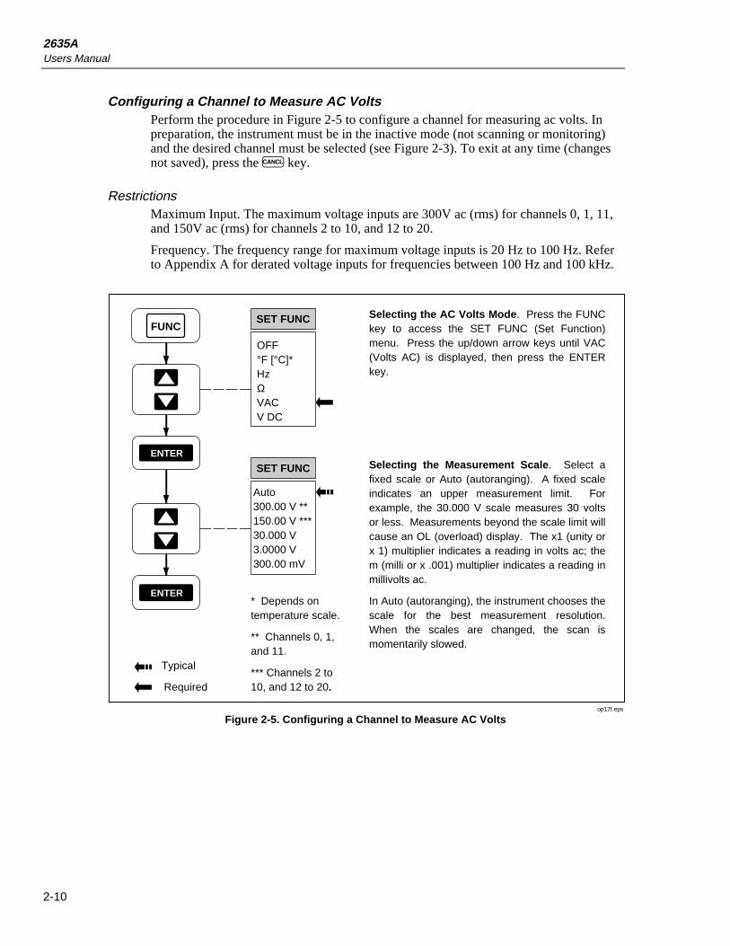
2635AUsers Manual
2-10
Configuring a Channel to Measure AC VoltsPerform the procedure in Figure 2-5 to configure a channel for measuring ac volts. Inpreparation, the instrument must be in the inactive mode (not scanning or monitoring)and the desired channel must be selected (see Figure 2-3). To exit at any time (changesnot saved), press the C key.
RestrictionsMaximum Input. The maximum voltage inputs are 300V ac (rms) for channels 0, 1, 11,and 150V ac (rms) for channels 2 to 10, and 12 to 20.
Frequency. The frequency range for maximum voltage inputs is 20 Hz to 100 Hz. Referto Appendix A for derated voltage inputs for frequencies between 100 Hz and 100 kHz.
FUNC
ENTER
SET FUNC
OFF°F [°C]*HzΩVACV DC
Auto300.00 V **150.00 V ***30.000 V3.0000 V300.00 mV
ENTER
SET FUNC
Typical
Required
Selecting the AC Volts Mode. Press the FUNC key to access the SET FUNC (Set Function) menu. Press the up/down arrow keys until VAC (Volts AC) is displayed, then press the ENTER key.
Selecting the Measurement Scale. Select a fixed scale or Auto (autoranging). A fixed scale indicates an upper measurement limit. For example, the 30.000 V scale measures 30 volts or less. Measurements beyond the scale limit will cause an OL (overload) display. The x1 (unity or x 1) multiplier indicates a reading in volts ac; the m (milli or x .001) multiplier indicates a reading in millivolts ac.
In Auto (autoranging), the instrument chooses the scale for the best measurement resolution. When the scales are changed, the scan is momentarily slowed.
* Depends on temperature scale.
** Channels 0, 1, and 11.
*** Channels 2 to 10, and 12 to 20.
op17f.eps
Figure 2-5. Configuring a Channel to Measure AC Volts

Front Panel OperationsConfiguring a Measurement Channel 2
2-11
Configuring a Channel to Measure ResistancePerform the procedure in Figure 2-6 to configure a channel for measuring resistance. Inpreparation, the instrument must be in the inactive mode (not scanning or monitoring)and the desired channel must be selected (see Figure 2-3). To exit at any time (changesnot saved), press the C key.
The resistance to be measured can be connected using one channel (two-terminalconnection) or two channels (four-terminal connection). The four-terminal connectionprovides increased measurement precision. The two channels used in a four-terminalconnection are a decade apart (n and n+10), for example, channel 3 (n) and 13 (n+10).Only the lower channel is configured.
RestrictionsFour-Terminal Channels. Four-Terminal configurations are limited to channels 1 to 10(n). The channel a decade higher (n + 10) is automatically reserved for use.
FUNC
ENTER
SET FUNC
OFF°F [°C]*HzΩVACV DC
Auto10.000 M3.0000 M300.00 k30.000 k3.0000 k300.00
ENTER
SET FUNC
Typical
Required
Selecting the Resistance Mode. Press the FUNC key to access the SET FUNC (Set Function) menu. Press the up/down arrow keys until Ω (ohms) is displayed, then press the ENTER key.
Selecting the Measurement Scale. Select a fixed scale or Auto (autoranging). A fixed scale indicates an upper measurement limit. For example, the 30.000 kΩ scale measures 30 kΩ ohms or less. Measurements beyond the scale limit will cause an OL (overload) display. The x1 (unity or x 1) multiplier indicates a reading in ohms; the k (kilo or x 1,000) multiplier indicates a reading in kilohms; the M (mega or x 1,000,000) multiplier indicates a reading in megohms.
In Auto (autoranging), the instrument chooses the scale for the best measurement resolution. When scales are changed, the scan is momentarily slowed.
* Depends on temperature scale.
** Channels 1 to 10.
2T4T**
SET FUNC
ENTER
Selecting the Terminal Mode. Select the two-terminal (2T) or four-terminal (4T) mode. 4T automatically clears configuration data from the channel a decade higher (n+10). For example, selecting channel 3 for 4T operation will automatically clear channel 13 of all configuration data and lock it out from further use.
op18f.eps
Figure 2-6. Configuring a Channel to Measure Resistance

2635AUsers Manual
2-12
Configuring a Channel to Measure FrequencyPerform the procedure in Figure 2-7 to configure a channel for measuring frequency. Inpreparation, the instrument must be in the inactive mode (not scanning or monitoring)and the desired channel must be selected (see Figure 2-3). To exit at any time (changesnot saved), press the C key.
RestrictionsFrequency Range. The frequency range for measurements is 15 Hz minimum to greaterthan 1 MHz.
Maximum Input. The maximum voltage inputs are 300V ac (rms) for channels 0, 1, 11,and 150V ac (rms) for channels 2 to 10, and 12 to 20. The frequency range for maximumvoltage inputs is 15 Hz to 100 Hz. Refer to Appendix A for derated voltage inputs forfrequencies between 100 Hz and 100 kHz.
FUNC
ENTER
SET FUNC
OFF°F [°C]*HzΩVACV DC
Auto1.0000 MHz900.00 kHz90.000 kHz9.0000 kHz900.00 Hz
ENTER
SET FUNC
Typical
Required
Selecting the Frequency Mode. Press the FUNC key to access the SET FUNC (Set Function) menu. Press the up/down arrow keys until Hz (Hertz) is displayed, then press the ENTER key.
Selecting the Measurement Scale. Select a fixed scale or Auto (autoranging). A fixed scale indicates an upper measurement limit. For example, the 90.000 kHz scale measures 90 kHz or less. Measurements beyond the scale limit will cause an OL (overload) display. The x1 (unity or x 1) multiplier indicates a reading in Hz; the k (kilo or x 1,000) multiplier indicates a reading in kilohertz; the M (mega or x 1,000,000) multiplier indicates a reading in megahertz.
In Auto (autoranging), the instrument chooses the scale for the best measurement resolution. There are no scanning delays with frequency autoranging.
* Depends on temperature scale.
op19f.eps
Figure 2-7. Configuring a Channel to Measure Frequency

Front Panel OperationsConfiguring a Measurement Channel 2
2-13
Configuring a Channel to Measure TemperaturePerform the procedure in Figure 2-8 to configure a channel for measuring temperaturewith thermocouples, or Figure 2-9 to measure temperature with resistance-temperaturedetectors (RTDs). In preparation, the instrument must be in the inactive mode (notscanning or monitoring) and the desired channel must be selected (see Figure 2-3). Toexit at any time (changes not saved), press the C key. The temperature scale, ºC or ºF,is set by the Temperature-Toggle Power-On procedure (see Figure 2-2). When undercomputer control, an open thermocouple default can be set by the TEMP_CONFIGcommand.
ThermocouplesThermocouples are formed by joining two wires of dissimilar metals, which produce avoltage proportional to the temperature of the wire junction. The instrument conditionsthis voltage into temperature measurements. Voltage conditioning includescompensation for the type of thermocouple used and measurement-processcompensation that uses a reference temperature sensor built into the Input Module(channels 1 to 20). The front panel terminals (channel 0) cannot be used forthermocouples. The instrument supports nine standard thermocouples, each identifiedwith an American National Standards Institute (ANSI) alpha character (except [ ]): J,[C], B, S, R, N, T, E, or K. A thermocouple type is selected as part of the channelconfiguration. Table 2-3 summarizes the ranges and characteristics of the supportedthermocouples. The instrument displays "otc" when an open thermocouple is detected(as selected with the TEMP_CONFIG command - see Chapter 4). A type "T"thermocouple is supplied with the instrument.
Resistance-Temperature DetectorsResistance-Temperature Detectors (RTDs) are formed from coils or strips of metal,usually platinum, the resistance of which varies with temperature. The instrumentconditions this resistance into temperature measurements. The instrument supports anyplatinum RTD that is calibrated to the IEC 751 Standard (a=0.00385 ohms/ohm/ºC).RTDs are characterized by their resistance at 0 ºC, which is called the "ice point" or R0.The most common R0 is 100 ohms. The instrument supports any IEC 751 Platinum RTDwith an R0 from 000.00 to 999.99, with a default of R0=100.00. Since RTDs areresistance devices, they can be connected to the instrument using one channel (two-terminal connection) or two channels (four-terminal connection). A four-channelconfiguration provides increased measurement precision. Some RTDs can be purchasedin a four-terminal configuration, facilitating a four-terminal connection. The twochannels used in a four-terminal connection are a decade apart (n and n+10), forexample, channel 3 (n) and 13 (n+10). Only the lower channel is configured.
Thermocouple Restrictions:Channel 0. Thermocouple measurements cannot use channel 0.
Open Thermocouple. The instrument displays OTC when an open thermocouple isdetected and ignores the channel while scanning.
Resistance Temperature Detectors Restrictions:Four-Terminal Channels. Four-Terminal configurations are limited to channels 1 to 10(n). The channel a decade higher (n + 10) is automatically reserved for use.
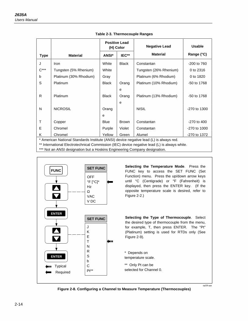
2635AUsers Manual
2-14
Table 2-3. Thermocouple Ranges
Positive Lead(H) Color Negative Lead Usable
Type Material ANSI* IEC** Material Range (°C)
J Iron White Black Constantan -200 to 760
C*** Tungsten (5% Rhenium) White Tungsten (26% Rhenium) 0 to 2316
b Platinum (30% Rhodium) Gray Platinum (6% Rhodium) 0 to 1820
S Platinum Black Orang
e
Platinum (10% Rhodium) -50 to 1768
R Platinum Black Orang
e
Platinum (13% Rhodium) -50 to 1768
N NICROSIL Orang
e
NISIL -270 to 1300
T Copper Blue Brown Constantan -270 to 400
E Chromel Purple Violet Constantan -270 to 1000
K Chromel Yellow Green Alumel -270 to 1372* American National Standards Institute (ANSI) device negative lead (L) is always red.** International Electrotechnical Commission (IEC) device negative lead (L) is always white.*** Not an ANSI designation but a Hoskins Engineering Company designation.
FUNC
ENTER
SET FUNC
OFF°F [°C]*HzΩVACV DC
ENTER
SET FUNC
Typical
Required
Selecting the Temperature Mode. Press the FUNC key to access the SET FUNC (Set Function) menu. Press the up/down arrow keys until °C (Centigrade) or °F (Fahrenheit) is displayed, then press the ENTER key. (If the opposite temperature scale is desired, refer to Figure 2-2.)
Selecting the Type of Thermocouple. Select the desired type of thermocouple from the menu, for example, T, then press ENTER. The "Pt" (Platinum) setting is used for RTDs only (See Figure 2-9).
* Depends on temperature scale.
** Only Pt can be selected for Channel 0.
JKETNRSbCPt**
op20f.eps
Figure 2-8. Configuring a Channel to Measure Temperature (Thermocouples)
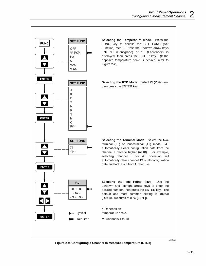
Front Panel OperationsConfiguring a Measurement Channel 2
2-15
FUNC
ENTER
SET FUNC
OFF°F [°C]*HzΩVACV DC
ENTER
SET FUNC
Typical
Required
Selecting the Temperature Mode. Press the FUNC key to access the SET FUNC (Set Function) menu. Press the up/down arrow keys until °C (Centigrade) or °F (Fahrenheit) is displayed, then press the ENTER key. (If the opposite temperature scale is desired, refer to Figure 2-2.)
Selecting the RTD Mode. Select Pt (Platinum), then press the ENTER key.
* Depends on temperature scale.
** Channels 1 to 10.
2T4T**
SET FUNC
ENTER
Selecting the Terminal Mode. Select the two-terminal (2T) or four-terminal (4T) mode. 4T automatically clears configuration data from the channel a decade higher (n+10). For example, selecting channel 3 for 4T operation will automatically clear channel 13 of all configuration data and lock it out from further use.
Ro
ENTER
Selecting the "Ice Point" (R0). Use the up/down and left/right arrow keys to enter the desired number, then press the ENTER key. The default and most common setting is 100.00 (R0=100.00 ohms at 0 °C [32 °F]).
0 0 0 . 0 0- to -
9 9 9 . 9 9
JKETNRSbCPt**
op21f.eps
Figure 2-9. Configuring a Channel to Measure Temperature (RTDs)

2635AUsers Manual
2-16
Configuring a Channel OffPerform the procedure in Figure 2-10 to configure a channel for off (no measurement).In preparation, the instrument must be in the inactive mode (not scanning or monitoring)and the desired channel must be selected (see Figure 2-3). To exit at any time (changesnot saved), press the C key. When a channel is OFF, it cannot be scanned ormonitored. When a channel function is changed, alarm limits and scaling (Mx+B) forthat channel are changed to their default conditions.
FUNC
ENTER
SET FUNC
OFF°F [°C]*HzΩVACV DC
Typical
Required
Selecting the OFF Mode. Press the FUNC key to access the SET FUNC (Set Function) menu. Press the up/down arrow keys until OFF is displayed, then press the ENTER key.
* Depends on temperature scale.
op22f.eps
Figure 2-10. Configuring a Channel Off
Setting Operating ConditionsAfter the channels are configured for the desired measurement parameter, set thefollowing operating conditions to support the intended instrument function:
• Setting the Scan Interval [Default - 0:00:00 (Continuous)] (Figure 2-11)
• Setting the Measurement Rate [Default - Slow] (Figure 2-12)
• Setting the Alarms [Default - Alarms off] (Figures 2-13)
• Setting the Mx+B Scaling [Default - 1x+0 (no scaling)] (Figure 2-14)
The instrument default settings for each of the above are shown.

Front Panel OperationsSetting Operating Conditions 2
2-17
Setting the Scan IntervalPerform the procedure in Figure 2-11 to set the time between starts of measurementscans. In preparation, the instrument must be in the inactive mode (not scanning ormonitoring). To exit at any time (changes not saved), press the C key. The scanninginterval format is HOURS:MINUTES:SECONDS. The minimum is 0:00:00 (continuousscanning [default]); the maximum is 9:99:99 (9 hours, 99 minutes, 99 seconds). The scaninterval is divided into two portions: the measurement interval when measurements areactually taken, and the time-out interval that completes the overall scan duration. Forexample, if 10 channels can be measured in 8 seconds, and the scanning interval is setfor 30 seconds, the first 8 seconds are used for measurement, while the remaining 22seconds are used to time out. If the scanning interval is set to less than the measurementrate, the effect is continuous scanning. For example, if 10 channels can be measured in 8seconds and the scanning interval is set for 5 seconds, scanning is continuous. To speedup the measurement rate, refer to Figure 2-12.
Typical
Required
SET
ENTER
Setting the Scan Interval. Press the INTVL (Interval) key to access the scan time menu. The format is HOURS:MINUTES:SECONDS. Press the up/down and left/right arrow keys to select and configure each column in the menu. For example, a scan interval of 1 hour, 25 minutes, and 33 seconds would be formatted as 1:25:33. The column being configured will have a bright display. When the display shows the desired interval, press the ENTER key.
0: 0 0 : 0 0- to -
9: 9 9 : 9 9
INTVL
op23f.eps
Figure 2-11. Setting the Scan Interval

2635AUsers Manual
2-18
Setting the Measurement RatePerform the procedure in Figure 2-12 to set a fast or slow [default] measurement rate.The measurement rate affects the time required to scan the configured channels.However, the fast mode sacrifices one digit of measurement resolution. For example, atemperature reading of 22.4ºC in the slow mode would become 22ºC in the fast mode, or27.858V dc in the slow mode would become 27.86 V dc in the fast mode. The fast modeis normally used to capture rapidly changing measurements or to speed up themeasurement portion of the scan interval.
Typical
Required
RAtE
ENTER
Setting the Measurement Rate. Press the SHIFT key and then the right-arrow key to access the measurement rate menu. Press the up/down arrow keys to select either SLO (Slow) or FASt (Fast), then press the ENTER key.
FAStSLO
SHIFT
op24f.eps
Figure 2-12. Setting the Measurement Rate
Setting the AlarmsPerform the procedure in Figure 2-13 to set alarm limits for any configured channel. Inpreparation, the instrument must be in the inactive mode (not scanning or monitoring)and the desired channel must be configured with a measurement function (see Figures 2-4 to 2-9) and selected (see Figure 2-3). To exit at any time, press the C key; however,any alarm parameters previously entered will remain. Two alarm limits, alarm 1 andalarm 2, can be defined for each channel. If applied to a channel with Mx+B scaling, thealarm is based on the scaled values. An alarm occurs when the measured value on thechannel moves above the HI (High) or below the LO (Low) value. Alarms can startautoprinting (Figure 5-3), start scanning with the Monitor-Alarm trigger option (Figure2-19), or trigger other functions via the rear panel digital outputs. In the inactive mode,any selected channel that is programmed with alarm limits will display LIMIT plus 1and/or 2 to show which alarms have been set. In the different operating modes, the frontpanel will provide an indication of a channel in an alarm condition. Each is discussedbelow.
Alarm Indications While ScanningIf a scanned channel is in an alarm condition during the scan, the ALARM annunciator isturned on (dim display). If all alarm conditions clear during the next scan, the ALARMannunciator is turned off. See Figure 2-15 for information about the Scan Mode.

Front Panel OperationsSetting Operating Conditions 2
2-19
Alarm Indications While MonitoringIf the channel being monitored is in an alarm condition, the alarm limit 1 and/or 2annunciators will be turned on, and the ALARM annunciator blinks bright/dim. Thealarm limit annunciator indicates which alarm has been exceeded. If the monitoredchannel is not in alarm, the ALARM annunciator will be off, unless scanning and someother channel is in alarm, then the ALARM indicator has a steady dim display. SeeFigure 2-17 for information about the Monitor Mode.
Alarm Indications While ReviewingIf the channel being reviewed had been in an alarm condition, the ALARM and alarmlimit 1 and/or 2 annunciators will be turned on. The alarm limit annunciator indicateswhich alarm has been exceeded. See Figure 2-18 for information about the ReviewMode.
Clearing Alarm Parameters from a ChannelTo clear alarm parameters from a channel, the alarm can be programmed to OFF for bothalarm 1 and alarm 2, or the channel function can be changed to any other selection,including OFF.
Alarm Outputs for Channel 0 to 3 Using the Alarm Outputs ConnectorA dedicated transistor-transistor logic (TTL) voltage output is available for channel 0 tochannel 3 alarms, via the rear panel ALARM OUTPUTS connector. (See Chapter 1 ofthis manual for connection information.)If a channel is not in alarm, the voltage output ata connector terminal is a logical high (nominal +5V dc); if a channel is in alarm, theoutput is a logical low (nominal +0.7V dc). Alarm outputs are set following each scan.As shown in Table 2-4, there are 16 different alarm combinations. The decimalequivalent of the binary half-byte formed by Channel 3 to Channel 0 has significance inautoprinting operations. (See the following discussion on autoprinting.)
Alarm Outputs for Channels 4 to 20 Using the Digital I/O ConnectorA shared transistor-transistor logic (TTL) voltage output is available for channel 4 tochannel 20 alarms via the rear panel DIGITAL I/O connector, using terminals I/O 7 toI/O 4. (See Chapter 1 of this manual for connection information.)If a channel is not inalarm, the voltage output at a connector terminal is a logical high (nominal +5V dc); if achannel is in alarm, the output is a logical low (nominal +0.7V dc). Alarm outputs are setfollowing each scan. As shown in Table 2-5, the alarm outputs for channels 4 to 20 areORed in groups. For example, a logical low at I/O 7 indicates that channel 7 or 11 or 15or 19 is in an alarm condition. Dedicated alarm channels are available only for channels0 to 3 (see the above). Assigning alarms to channels 4 to 20 does not disable theassociated I/O output from use by commands from the computer interface. (See using the"Digital Input/Output Lines" under "Additional Features.") The decimal equivalent ofthe binary byte formed by I/O 7 to I/O 0 has significance in autoprinting operations (seethe following discussion) and for certain commands in the instrument command set, e.g.,LOG?.
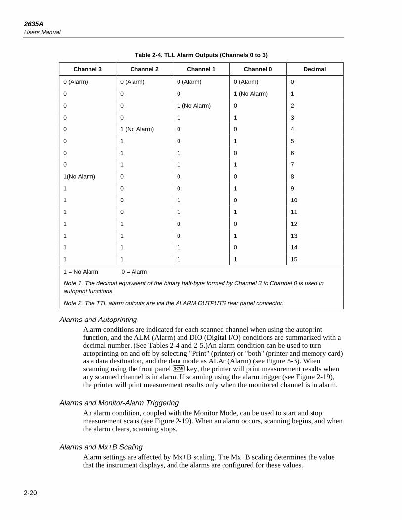
2635AUsers Manual
2-20
Table 2-4. TLL Alarm Outputs (Channels 0 to 3)
Channel 3 Channel 2 Channel 1 Channel 0 Decimal
0 (Alarm) 0 (Alarm) 0 (Alarm) 0 (Alarm) 0
0 0 0 1 (No Alarm) 1
0 0 1 (No Alarm) 0 2
0 0 1 1 3
0 1 (No Alarm) 0 0 4
0 1 0 1 5
0 1 1 0 6
0 1 1 1 7
1(No Alarm) 0 0 0 8
1 0 0 1 9
1 0 1 0 10
1 0 1 1 11
1 1 0 0 12
1 1 0 1 13
1 1 1 0 14
1 1 1 1 15
1 = No Alarm 0 = Alarm
Note 1. The decimal equivalent of the binary half-byte formed by Channel 3 to Channel 0 is used inautoprint functions.
Note 2. The TTL alarm outputs are via the ALARM OUTPUTS rear panel connector.
Alarms and AutoprintingAlarm conditions are indicated for each scanned channel when using the autoprintfunction, and the ALM (Alarm) and DIO (Digital I/O) conditions are summarized with adecimal number. (See Tables 2-4 and 2-5.)An alarm condition can be used to turnautoprinting on and off by selecting "Print" (printer) or "both" (printer and memory card)as a data destination, and the data mode as ALAr (Alarm) (see Figure 5-3). Whenscanning using the front panel Q key, the printer will print measurement results whenany scanned channel is in alarm. If scanning using the alarm trigger (see Figure 2-19),the printer will print measurement results only when the monitored channel is in alarm.
Alarms and Monitor-Alarm TriggeringAn alarm condition, coupled with the Monitor Mode, can be used to start and stopmeasurement scans (see Figure 2-19). When an alarm occurs, scanning begins, and whenthe alarm clears, scanning stops.
Alarms and Mx+B ScalingAlarm settings are affected by Mx+B scaling. The Mx+B scaling determines the valuethat the instrument displays, and the alarms are configured for these values.

Front Panel OperationsSetting Operating Conditions 2
2-21
Table 2-5. TTL Alarm Outputs (Channels 4 to 20)
Channels Channels Channels Channels7 -or- 6 -or- 5 -or- 4 -or-11 -or- 10 -or- 9 -or- 8 -or-15 -or- 14 -or- 13 -or- 12 -or-
19 18 17 16 -or-20 -or-
I/O 7 I/O 6 I/O 5 I/O 4 Decimal0 (Alarm) 0 (Alarm) 0 (Alarm) 0 (Alarm) 310 1 (No Alarm) 1 (No Alarm) 1 (Alarm) 1271 (No Alarm) 0 1 1 1911 1 0 1 2231 1 1 0 2391 1 1 1 2551 = No Alarm 0 = AlarmNote 1. The decimal equivalent of the binary byte formed by Channel 4 to Channel 20 is used in autoprintand computer functions. The decimal values shown here are based on I/O 3 to I/O 0 being equal to logical 1.
Note 2. The above shows the least complicated Digital I/O alarm configurations. Multiple alarms plus the useof I/O terminals 3 to 0 can conceivably use all 255 digital I/O combinations.
Note 3. The TTL alarm outputs are via the DIGITAL I/O rear-panel connector
Example: A logical 0 at I/O 7 terminals indicates an alarm condition for channel 7, or 11, or 15, or 19. Onlychannels 0 to 3 have dedicated alarm outputs on the ALARM OUTPUTS connector.

2635AUsers Manual
2-22
Typical
Required
LIMIT
ENTER
Selecting Alarm 1 or Alarm 2. Press the ALRM (Alarm) key to access the alarm selection menu. Use the up/down arrow keys to select alarm 1 or 2, then press the ENTER key.
ALRM
1
2
LIMIT
ENTER
LIMIT
OFFHILO
ENTER
LIMIT
X . X X X X
X X . X X X
X X X . X X
X X X X . X
ENTER
LIMIT
ENTER
x1mMk
Selecting the Alarm Numerical Value. Press the up/down and left/right arrow keys to enter a five digit number that defines the numerical value for the alarm, ignoring the decimal point or scale multiplier. The column being configured will have a bright display. For example, for an alarm of 132.75V ac, enter +13275. When the entry is correct, press the ENTER key.
Selecting the Alarm Decimal Value. Press the left/right arrow keys to position the decimal point in the number selected in the previous step. For the example above, the settings would be 132.75. When the decimal point is correct, press the ENTER key.
Selecting the Alarm Mode. Press the up/down arrow keys to select an alarm mode, OFF (Off), HI (High), or LO (Low), then press the ENTER key.
Selecting the Alarm Scale Multiplier. Press the up/down arrow keys to select the desired multiplier: x1 (x1), m (x .001), M (x1,000,000), or k (x1,000). For the example above, the 132.75 multiplier would be x1. When the multiplier is correct, press the ENTER key. If alarm 1 is configured, the procedure continues for alarm 2. If alarm 2 is configured, the procedure terminates.
± 0 0 0 0 0- to -
± 9 9 9 9 9
op25f.eps
Figure 2-13. Setting the Alarms
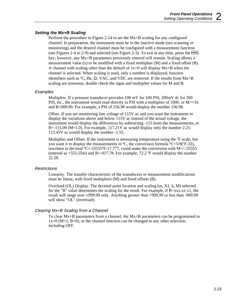
Front Panel OperationsSetting Operating Conditions 2
2-23
Setting the Mx+B ScalingPerform the procedure in Figure 2-14 to set the Mx+B scaling for any configuredchannel. In preparation, the instrument must be in the inactive mode (not scanning ormonitoring) and the desired channel must be configured with a measurement function(see Figures 2-4 to 2-9) and selected (see Figure 2-3). To exit at any time, press the Ckey; however, any Mx+B parameters previously entered will remain. Scaling allows ameasurement value (x) to be modified with a fixed multiplier (M) and a fixed offset (B).A channel with scaling other than the default of 1x+0 will display Mx+B when thechannel is selected. When scaling is used, only a number is displayed; functionidentifiers such as ºC, Hz, Ω, VAC, and VDC are removed. If the results from Mx+Bscaling are nonsense, double check the signs and multiplier values for M and B.
ExamplesMultiplier. If a pressure transducer provides 100 mV for 100 PSI, 200mV dc for 200PSI, etc., the instrument would read directly in PSI with a multiplier of 1000, or M=+1kand B=000.00. For example, a PSI of 156.98 would display the number 156.98.
Offset. If you are monitoring line voltage of 115V ac and you want the instrument todisplay the variations above and below 115V ac instead of the actual voltage, theinstrument would display the differences by subtracting -115 from the measurements, orB=-115.00 (M=1.0). For example, 117.21V ac would display only the number 2.21;113.45V ac would display the number -1.55.
Multiplier and Offset. If the instrument is measuring temperature using the ºF scale, butyou want it to display the measurements in ºC, the conversion formula ºC=5/9(ºF-32),rewritten in decimal ºC=.55555ºF-17.777, could make the conversion with M=+.55555(entered as +555.55m) and B=-017.78. For example, 72.2 ºF would display the number22.28.
RestrictionsLinearity. The transfer characteristic of the transducers or measurement modificationsmust be linear, with fixed multipliers (M) and fixed offsets (B).
Overload (OL) Display. The decimal point location and scaling (m, X1, k, M) selectedfor the "B" value determines the scaling for the result. For example, if B=xxx.xx x1, theresult will range over ±999.99 only. Anything greater than +999.99 or less than -999.99will show "OL" (overload).
Clearing Mx+B Scaling from a ChannelTo clear Mx+B parameters from a channel, the Mx+B parameters can be programmed to1x+0 (M=1, B=0), or the channel function can be changed to any other selection,including OFF.

2635AUsers Manual
2-24
Typical
Required
SET Mx+B
ENTER
X . X X X X
X X . X X X
X X X . X X
X X X X . X
ENTER
ENTER
x1mMk
Selecting the M Numerical Value . Press the Mx+B key to access the Mx+B menu. Press the up/down and left/right arrow keys to enter a five digit number that defines the numerical value for the measurement multiplier, ignoring the decimal point or scale multiplier. The column being configured has a bright display. For example, for an M of 1000 (1k), enter +01000. When the entry is correct, press the ENTER key.
Selecting the M Decimal Value . Press the left/right arrow keys to position the decimal point in the number selected in the previous step. For the example above, the setting would be +01.000. When the decimal point is correct, press the ENTER key.
Selecting the M Scale Modifier . Press the up/down arrow keys to select the desired scale modifier: X1 (x1), m (x .001), M (x1,000,000), or k (x1,000). For the example above, the +01.000 scale modifier would be k. When the scale modifier is correct, press the ENTER key.
± 0 0 0 0 0- to -
± 9 9 9 9 9
SET Mx+B
SET Mx+B
Mx+B
A(Continued on the next page)
op26f.eps
Figure 2-14. Setting the Mx+B Scaling

Front Panel OperationsSetting Operating Conditions 2
2-25
Typical
Required
ENTER
X . X X X X
X X . X X X
X X X . X X
X X X X . X
ENTER
ENTER
x1mMk
Selecting the B Numerical Value . Press the up/down and left/right arrow keys to enter a five digit number that defines the numerical value for the measurement offset, ignoring the decimal point or scale multiplier. The column being configured has a bright display. For example, for a B of -115, enter -11500. When the entry is correct, press the ENTER key.
Selecting the B Decimal Value . Press the left/right arrow keys to position the decimal point in the number selected in the previous step. For the example above, the setting would be -115.00. When the decimal point is correct, press the ENTER key.
Selecting the B Scale Modifier . Press the up/down arrow keys to select the desired scale modifier: X1 (x1), m (x .001), M (x1,000,000), or k (x1,000). For the example above, the -115.00 scale modifier would be x1. When the scale modifier is correct, press the ENTER key.
SET Mx+B
SET Mx+B
A (Continued from the previous page)
SET Mx+B
± 0 0 0 0 0- to -
± 9 9 9 9 9
op26af.eps
Figure 2-14. Setting the Mx+B Scaling (cont)

2635AUsers Manual
2-26
Operating ModesWith the channels configured and operating conditions set, the instrument is ready foroperation in one of the following modes:
• Using the Scan Mode (Figure 2-15)• Using the Monitor Mode (Figure 2-17)• Using the Review Mode (Figure 2-18)Each operating mode is discussed below. To modify the operating mode with additionalfeatures, such as using the scan triggering, refer to the next main headings in thischapter, "Additional Features."
Using the Scan ModePerform the procedure in Figure 2-15 to start and stop the Scan Mode of operation. TheScan Mode can be started when the instrument is inactive, in Monitor (Figure 2-17), orReview (Figure 2-18). Measurement results can be sent to a memory card (see Chapter 3,"Memory Card Operations") and PC (see Chapter 4, "Computer Operations") or printer(see Chapter 5, "Printer Operations"). When using the Scan Mode with a memory card,consider each of the following topics. (Memory card error messages are summarized inFigure 2-16.)
Memory Card as a Data DestinationMeasurement data is not automatically sent to the memory card. Measurement data canbe sent to a printer/PC, to the memory card, to both printer/PC and memory card, or toneither. If either the printer/PC or memory card, or both are selected, the PRNannunciator will be on. See Figure 3-4 to set the destination and mode for sendingmeasurement data to the memory card.
Memory Card FormattingWhen the instrument is inactive (not scanning or monitoring), insert a memory card. Animmediate error Err 1/CArd indicates the memory card is not initialized (formatted). SeeFigure 3-3 to initialize a memory card.
Memory Card CapacityA memory card that fills during scanning displays the error Err 3/FULL, meaningreadings are being saved in internal memory (75 scans maximum) and another cardshould be inserted. The error changes to Err 4/FULL if the internal memory fills, savingonly the most recent 75 scans. When inserted, the replacement card is updated with thescans in memory.
Memory Card FilesData files (dAtxx) are opened manually (see Figure 3-8) or prompted by pressing Q.Press E to accept file names or use the up/down and left/right arrow keys to select afile name and then press E. If a data file cannot be opened, error Err 2/FILE will bedisplayed, meaning all files dAt00 to dAt99 already exist or the selected file name isalready assigned.
Memory Card Exchange During ScanningEject the active card when the BUSY indicator is off and replace with another card. Theinstrument opens the same file name on the new card. If this file cannot be opened, Err

Front Panel OperationsOperating Modes 2
2-27
3/bAd is displayed (see Figure 2-16). Err4/bAd indicates the internal memory is full,saving only the most recent 75 scans. The new card is updated with the scans in memory.
Memory Card Data ExtractionMeasurement data recorded onto a memory card can be read only by a PC runningStarter or Logger applications software. If you want to have a copy of the measurementdata when it is being recorded, connect a printer during scan operations (see Chapter 5,Printer Operation). If using a printer, verify the data destination is "both" (memorycard/printer) (see Figure 5-3).
SCAN Starting the Scan Mode . Press the SCAN key to start scanning. If the data destination includes the memory card and a data file has not been opened, a dAtxx file will be displayed. If an error message appears, refer to Figure 2-16.
SHIFT
SCANCH
SCAN
SCAN
- OFF -
Stopping the Scan Mode . Press the SCAN key again to stop the scan mode (-OFF- will be displayed momentarily). If SCAN is pressed during the measurement interval, the measurements will be completed.
Starting the Single Scan Mode . Press the SHIFT key then then SCAN key for a single measure-ment scan. If the data destination includes the memory card and a data file has not been opened, a dAtxx file will be displayed. If an error message appears, refer to Figure 2-16.
SCAN
SCAN ON
SCAN OFF
SINGLESCAN
0:00:00
SCAN
CH
0:00:00
ENTER
OPEn
dAtxx
Opening a Data (dAtxx) File . Press ENTER to open the suggested file or use the cursor keys to select a file name (00 to 99), then press ENTER. If an error message appears, refer to Figure 2–16. Press the CANCL key to exit without opening a file or starting scanning.
ENTER
OPEn
dAtxx
Opening a Data (dAtxx) File . The suggested dAtxx file can be opened by pressing ENTER, or the cursor keys can be used to select a file name (00 to 99), then press ENTER. If an error message appears, refer to Figure 2-16. Press the CANCL key to exit without opening a file.
Path to OPEndAtxx menu.
Path to OPEn dAtxx menu.
op27f.eps
Figure 2-15. Using the Scan Mode
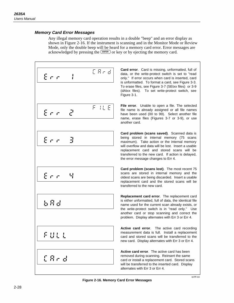
2635AUsers Manual
2-28
Memory Card Error MessagesAny illegal memory card operation results in a double "beep" and an error display asshown in Figure 2-16. If the instrument is scanning and in the Monitor Mode or ReviewMode, only the double beep will be heard for a memory card error. Error messages areacknowledged by pressing the E or key or by ejecting the memory card.
Card error. Card is missing, unformatted, full of data, or the write-protect switch is set to "read only." If error occurs when card is inserted, card is unformatted. To format a card, see Figure 3-3. To erase files, see Figure 3-7 (SEtxx files) or 3-9 (dAtxx files). To set write-protect switch, see Figure 3-1.
File error. Unable to open a file. The selected file name is already assigned or all file names have been used (00 to 99). Select another file name, erase files (Figures 3-7 or 3-9), or use another card.
Card problem (scans saved). Scanned data is being stored in internal memory (75 scans maximum). Take action or the internal memory will overflow and data will be lost. Insert a usable replacement card and stored scans will be transferred to the new card. If action is delayed, the error message changes to Err 4.
Card problem (scans lost). The most recent 75 scans are stored in internal memory and the oldest scans are being discarded. Insert a usable replacement card and the stored scans will be transferred to the new card.
Replacement card error. The replacement card is either unformatted, full of data, the identical file name used for the current scan already exists, or the write-protect switch is in "read only." Use another card or stop scanning and correct the problem. Display alternates with Err 3 or Err 4.
Active card error. The active card recording measurement data is full. Install a replacement card and stored scans will be transferred to the new card. Display alternates with Err 3 or Err 4.
Active card error. The active card has been removed during scanning. Reinsert the same card or install a replacement card. Stored scans will be transferred to the inserted card. Display alternates with Err 3 or Err 4.
op28f.eps
Figure 2-16. Memory Card Error Messages

Front Panel OperationsOperating Modes 2
2-29
Using the Monitor ModePerform the procedure in Figure 2-17 to start and stop the Monitor Mode of operation.The Monitor Mode can be started when the instrument is in the inactive mode or in theScan Mode. The Monitor Mode commands the instrument to display the presentmeasurement for any selected channel (except channels set to OFF) and to display alarminformation if the channel is in alarm. If the Monitor Mode is used without the ScanMode, the instrument operates like a multimeter. If the Monitor Mode is used with theScan Mode, the instrument also operates like a multimeter but measurements can berecorded into memory, printed out, and reviewed (maximum, minimum, last values). TheMonitor-Alarm triggering option uses the Monitor Mode to start or stop scans when aselected channel goes into or out of alarm (see Figure 2-19). If the instrument is in theMonitor Mode and scanning using the memory card, any illegal memory card operationsare noted only with a double "beep." When you hear a double beep, exit the MonitorMode and investigate the memory card error (see Figure 2-16).
MON
- OFF -
MONITOR
ON
MONITOR
OFFMON
MON
CH
XX.XXX
Starting the Monitor Mode . Press the MON key to start the Monitor Mode. Use the up/down arrow keys to select any configured channel and display the current measurement. Any monitored channel using autoranging will display AUTO. When the instrument is in the Monitor Mode, an internal relay closes every 10 seconds as part of the meter housekeeping activities. Relay closures are heard as a series of low-level audio "clicks" coming from the instrument.
Stopping the Monitor Mode . Press the MON key again to stop the Monitor Mode (-OFF- will be displayed momentarily). If the meter is in the Scan Mode, the front panel changes to the scan channel/interval timer display.
MON
op29f.eps
Figure 2-17. Using the Monitor Mode

2635AUsers Manual
2-30
Using the Review ModePerform the procedure in Figure 2-18 to operate the Review Mode of operation. TheReview Mode is used any time during or after operation of the Scan Mode. While theinstrument is in the Scan Mode, the last, maximum, and measurements for each scannedchannel are stored in memory and updated with each scan, forming the Review Array.For example, during scan operations, N can be used to monitor the maximummeasurement of a channel in real time. The Review Array is cleared by a controlsequence (see Figure 2-18 below), or by changing any parameter of any channel or themeasurement rate. The Review Array can be printed out using the L key (see Figure5-4). If the instrument is in the Review Mode and scanning using the memory card, anyillegal memory card operations is noted only with a double "beep." If a double beep isheard, exit the Review Mode and check the memory card error (see Figure 2-16).
REVIEW
CH
REVIEW
REVIEW
LAST
MIN
MAX
REVIEW
Examining the Review Values . Press the REVIEW key to start the Review Mode. Use the up/down arrow keys to select the channel for review, then use the left/right arrow keys to view the LAST (Last), MIN (Minimum), and MAX (Maximum) values recorded during the past scan intervals (scan can be active or inactive). Repeat for each channel of interest. A series of dashes, - - - - -, indicates all review data has been cleared either by a control sequence (below), or by changing any parameter of any channel. OL indicates an overload. Press the REVIEW key to exit the Review Mode. If not cleared, review values will remain in memory for update with the next scan interval.
REVIEW
REVIEW
SHIFT
REVIEW
Clearing the Review Array . Press the Review key to start the Review Mode. Press the SHIFT key and then the REVIEW key to clear all review data from all channels. If the scan mode is not active, the display will change to dashes (- - - - -). If the scan mode is active, new values will appear. Press the REVIEW key again to exit the Review Mode.
REVIEW
- - - - -
op30f.eps
Figure 2-18. Using the Review Mode

Front Panel OperationsAdditional Features 2
2-31
Additional FeaturesThe following additional features allow the instrument to serve in a variety ofapplications:
• Scan Triggering Options (Figure 2-19)• Totalizer Operation (Figure 2-20)• Digital Input/Output Lines• Setting Date and Time (Figure 2-21)• Reading Instrument Software Versions (Figure 2-22)• Returning to the LOCAL Mode (Figure 2-23)• Front Panel Key Lockout Option (Figure 2-24)
Scan Triggering Options
Perform the procedure in Figure 2-19 to select a triggering option, which can be appliedwhen the instrument is in the inactive mode (not scanning or monitoring). Normally, ascan is started by pressing the Q key, but two options can be selected to start a scanfrom either an external trigger input or from a monitor-alarm condition. The Q keyoverrides a triggering option.
External Trigger
The external trigger input starts a scan from a contact closure or TTL input applied to theTR and GROUND inputs on the rear panel ALARM OUTPUTS connector (see Figure 1-7). This option lights the EXT TR annunciator.
Monitor-Alarm Trigger
The Monitor-Alarm trigger starts scanning from a channel that goes into an alarm whilebeing monitored in the Monitor Mode. When the monitored channel goes into alarm, theinstrument scans for as long as the alarm condition exists. This option lights the TRannunciator.
Triggering Options and Memory Card Operation
To verify the equipment setup when the memory card is used to record data, use theSingle Scan mode (see Figure 2-15) to record a single scan. Any problems with thememory card or setup can be observed and corrected. If a triggering option triggersscanning without an open memory card dAtxx file, the instrument will automaticallyopen a file when a usable memory card is in the instrument. If no memory card isinstalled or the memory card is not usable, the most recent 75 scans are saved in aninternal memory. To record the saved scans, insert a usable memory card and open a file(see Figure 3-8). The stored scans will be transferred to the card.

2635AUsers Manual
2-32
Typical
Required
TRIg
ENTER
Selecting a Trigger Option . Press the SHIFT key and then the MON key to access the trigger option menu. Press the up/down arrow keys to select either ALAr (Alarm) (Monitor-Alarm trigger), On (On) (External trigger), or OFF (Off) (no trigger option selected), then press the ENTER key.
ALArOnOFF
SHIFT
MON
op31f.eps
Figure 2-19. Scan Triggering Options
Totalizer OperationPerform the procedure in Figure 2-20 to use the totalizer feature. The totalizer count canbe monitored when the instrument is active or inactive. The totalizer is an internalcounter that sums contact closures or voltage transitions. Connection is at the rear panelDIGITAL I/O connector, pins SUM and GROUND. A contact closure between SUM andGROUND or a voltage transition applied to SUM (referenced to GROUND), will causethe totalizer to advance by one count. The maximum count allowed is 65535 and themaximum count rate is 5 kHz. Voltages trigger on a low-to-high transition at a nominalthreshold of +1.4 volts. A contact debounce feature is available when the instrument isoperated through a computer interface. (See Chapter 4, "Computer Operations.")

Front Panel OperationsAdditional Features 2
2-33
totAL
SHIFT
TOTAL
TOTAL
TOTAL
XXXXX
totAL
TOTAL
TOTAL
XXXXX
totAL
0
Reading the Totalizer Count . Press the TOTAL key to view the contents of the totalizer counter. The maximum count is 65535. If the maximum count is exceeded, the display will show OL (Overload). Press the TOTAL key again to exit. To reset the counter to zero, see below, Erasing the Totalizer Count.
Erasing the Totalizer Count . Press the TOTAL key to view the contents of the totalizer counter. Press the SHIFT key and then the TOTAL key to reset the counter to zero. Press the TOTAL key again to exit.
op32f.eps
Figure 2-20. Totalizer Operation
Digital Input/output LinesThere are no front panel controls or annunciators for the digital input/output (I/O) lines,I/O 7 to I/O 0. Connection to the eight I/O lines is via the rear panel DIGITAL I/Oconnector. If a logic low is applied to any line, the instrument treats it as an input; if theinstrument sets a line to logic low, the instrument treats it as an output. An output lowcondition takes precedence over an input high condition. All digital I/O lines arecontrolled by a computer interface (see Chapter 4, "Computer Operations"); however, asa default, lines I/O 7 to I/O 4 are used to output alarm status conditions for channels 4 to20 (see Table 2-5). An instrument-generated I/O line alarm output takes precedence overany other configuration.
All Digital I/O lines are set high (non-active) whenever power is cycled. These linesremain high until an alarm condition or computer interface command changes an outputstate.
NoteMeasurements taken with the Monitor function do not affect the digitaloutputs.

2635AUsers Manual
2-34
Setting Date and TimePerform the procedure in Figure 2-21 to set the instrument internal clock and calendar,which must be correct since measurements are tagged with this time and date. The built-in clock accuracy is a nominal one minute per month. Once set to the correct date andtime, clock and calendar operation is automatic and no further action is required.
Typical
Required
YEAR
ENTER
0 0- to -9 9
INTVL
SHIFT
Mn.dY
ENTER
0 0 . 0 0- to -
9 9 . 9 9
Selecting the Year . Press the SHIFT key and then the INTVL key to enter the date/time menu. With YEAR displayed, use the up/down and left/right arrow keys to select the two numbers for the correct year, for example, 94 for 1994, then press the ENTER key.
Selecting the Month and Day . With Mn.dY (Month.Day) displayed, use the up/down and left/right arrow keys to select four numbers for the correct month and day, for example, 07.21 for July 21, then press the ENTER key.
ENTER
Hr:Mn Selecting the Hour and Minute . With Hr:Mn (Hour:Minute) displayed, use the up/down and left/right arrow keys to select four numbers for the correct hour and minute (24-hour clock), for example, 14.38 for 2:38 pm, then press the ENTER key.
0 0 . 0 0- to -
9 9 . 9 9
op33f.eps
Figure 2-21. Setting Date and Time

Front Panel OperationsAdditional Features 2
2-35
Reading Instrument Software VersionsPerform the procedure in Figure 2-22 to view the version of the internal software that iscontrolling the instrument’s operation. Two software versions are identified with thisprocedure: the main software that operates all instrument functions, and the analog-to-digital software that operates the instrument analog-to-digital converter.
Reading the Software Versions . Press the left and right arrow keys simultaneously to generate a display that shows the software versions in the following format:
CANCL
6.3A 4.7
Main Software Version (Ver. 6.3 shown)
Analog-to-Digital Converter Software Version (Ver. 4.7 shown)
Press the CANCL key to exit.
+
op34f.eps
Figure 2-22. Reading Instrument Software Versions
Returning to the Local ModePerform the procedure in Figure 2-23 to return the instrument from the remote mode tothe local mode. When the instrument is operated over the RS-232 computer interface, thecomputer can disable all front panel controls except the Q key, which lights the REMannunciator (bright). If the REM annunciator is dim, the front panel keys are locked out(see Figure 2-24).
SHIFTReturning to the LOCAL Mode. Press the SHIFT key to return instrument control from RS–232 computer interface control to front panel control. When the computer has control, the REM annunciator is on (bright) and only the SCAN key operates, triggering single scans. A return to LOCAL control is allowed at any time, even during scanning. (This assumes the RWLS computer command has not been invoked. See Section 4 for information on commands REMS, RWLS, and LOCS.)
op35f.eps
Figure 2-23. Returning to LOCAL Mode
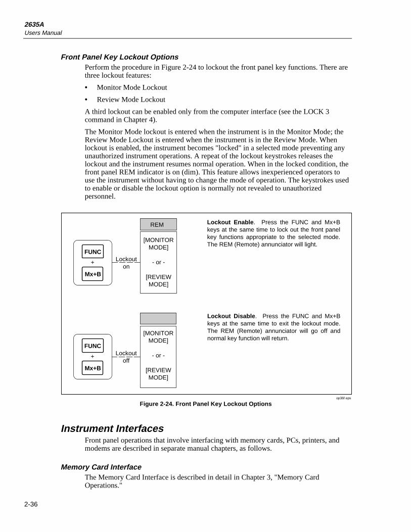
2635AUsers Manual
2-36
Front Panel Key Lockout OptionsPerform the procedure in Figure 2-24 to lockout the front panel key functions. There arethree lockout features:
• Monitor Mode Lockout
• Review Mode Lockout
A third lockout can be enabled only from the computer interface (see the LOCK 3command in Chapter 4).
The Monitor Mode lockout is entered when the instrument is in the Monitor Mode; theReview Mode Lockout is entered when the instrument is in the Review Mode. Whenlockout is enabled, the instrument becomes "locked" in a selected mode preventing anyunauthorized instrument operations. A repeat of the lockout keystrokes releases thelockout and the instrument resumes normal operation. When in the locked condition, thefront panel REM indicator is on (dim). This feature allows inexperienced operators touse the instrument without having to change the mode of operation. The keystrokes usedto enable or disable the lockout option is normally not revealed to unauthorizedpersonnel.
+
FUNC
Mx+B
REM
[MONITORMODE]
- or -
[REVIEWMODE]
Lockouton
+
FUNC
Mx+B
Lockoutoff
Lockout Enable. Press the FUNC and Mx+B keys at the same time to lock out the front panel key functions appropriate to the selected mode. The REM (Remote) annunciator will light.
Lockout Disable. Press the FUNC and Mx+B keys at the same time to exit the lockout mode. The REM (Remote) annunciator will go off and normal key function will return.
[MONITORMODE]
- or -
[REVIEWMODE]
op36f.eps
Figure 2-24. Front Panel Key Lockout Options
Instrument InterfacesFront panel operations that involve interfacing with memory cards, PCs, printers, andmodems are described in separate manual chapters, as follows.
Memory Card InterfaceThe Memory Card Interface is described in detail in Chapter 3, "Memory CardOperations."

Front Panel OperationsInstrument Interfaces 2
2-37
RS-232 Computer InterfaceThe Computer Interface is described in detail in Chapter 4, "Computer Operations."
Using the RS-232 Computer Interface With a PrinterThe Printer Interface is described in detail in Chapter 5, "Printer Operations."
Using the RS-232 Computer Interface With a ModemThe Modem Interface is described in detail in Chapter 6, "Modem Operations."

2635AUsers Manual
2-38

3-1
Chapter 3Memory Card Operations
Title Page
Summary of Memory Card Operations ............................................................. 3-3Memory Card Files ....................................................................................... 3-3Setup Files..................................................................................................... 3-4Data Files ...................................................................................................... 3-4Memory Card Capacity ................................................................................. 3-4Memory Card Battery ................................................................................... 3-5
Inserting and Removing the Memory Card ....................................................... 3-5Inserting a Memory Card .............................................................................. 3-5Removing a Memory Card............................................................................ 3-5Changing the Memory Card During Scanning.............................................. 3-5Setting the Memory Card Write-protect Feature .......................................... 3-5
Installing or Replacing the Memory Card Battery ............................................ 3-5Initializing a Memory Card ............................................................................... 3-7Recording Measurement Results During Scanning........................................... 3-8Setup File Procedures........................................................................................ 3-9
Using Setup Store.......................................................................................... 3-9Using Setup Load.......................................................................................... 3-10Using Setup Erase ......................................................................................... 3-11
Data File Procedures ......................................................................................... 3-12Using Data Open........................................................................................... 3-12Using Data Erase........................................................................................... 3-13
Setup and Data Files Directory ......................................................................... 3-14Setup and Data File Current Status ................................................................... 3-15Memory Card File Operations to and from a PC .............................................. 3-16

2635AUsers Manual
3-2
FUNC ALRM
Mx+B CANCEL ENTER
RATE
INTVL PRINT REVIEW
SHIFT LIST TOTAL
SINGLE
TRIGS
SCAN
MON
CLOCK MODE CLEAR
LOCAL COMM ZERO
mAmVDCAC
k Hz
REVIEWLASTHYDRA DATA BUCKET
300VMAX
COM V
M
CH
BUSY BATT
NFGFHMELCARD
NFGFHMELCARD
NFGFHMELCARD
256 KB
MELCARD
op81f.eps

Memory Card OperationsSummary of Memory Card Operations 3
3-3
Summary of Memory Card OperationsMemory card operations use a small, lightweight memory card (Figure 3-1) to save andload setup files (instrument configurations) and to record measurement data duringscanning. The memory card consists of static random-access memory (SRAM) poweredby an internal battery. Care should be taken not to drop or bend the card, and to keep itdry and away from high and low temperature extremes. Memory card operation isallowed in the same temperatures and humidity specifications that apply to theinstrument (see Appendix A, "Specifications"). SRAM memory cards are readilyavailable from supply houses serving the computer industry, or from Fluke (see Table 1-2, "Options and Accessories").
256 KB
SRAM
INSERTIONDIRECTION 68-PIN CONNECTOR
WRITE-PROTECT SWITCH
LITHIUM BATTERY 3 VOLTS
op37f.eps
Figure 3-1. Typical Memory Card
Memory Card FilesTwo types of memory card files are used. Files that store instrument configurations aresetup files, SEtxx, and files that store measurement data are data files, dAtxx, where xxis and integer from 00 to 99. The number xx can be assigned by the instrument orselected by the operator. When the assigned integer reaches 99, previous integersavailable from erased files or numbers skipped over are reassigned for subsequent newfiles. The memory card can contain a maximum of 100 SEtxx and 100 dAtxx files.

2635AUsers Manual
3-4
Setup FilesWhen the front panel controls have been used to configure channels for a particularinstrument application, including type of measurement, alarms, scaling, rate, and allother operating parameters, this configuration can be saved as a SEtxx files. If this is thefirst setup file saved on the memory card, the instrument will assign 00 for the file nameSEt00, or you can select your own file number. The instrument displays only the SEtxxportion, but all files are appended with the extension .HYD. Subsequent setup fileswould be Set01, Set02, and so on. The user should note the file name assigned orselected for a particular instrument configuration. A directory of card files are easilyviewed and print out using the directory feature (Figure 3-10). Setup files allow theentire instrument to b e configured for an operation in and instant. The “Logger”applications software can be used to create setup files that are tagged with a user-definedstring.
Data FilesData files, dAtxx, are opened automatically at scanning when the memory card isselected as a destination for measurement data. The display will indicate the file beingopened. For example, pressing the Q key will display dAt00 (for the first data file onthe memory card), which is acknowledged by pressing E, and then the scanningbegins. A file number can be selected as well. The instrument displays only the dAtxxportion, but all files are appended with the extension .HYD. If scanning is stopped, thenresumed without changing instrument configuration or the memory cared, the data willbe appended to the opened file. If any parameter is changed or the memory card ischanged, the next scan cycle will open a new dAtxx file. Extraction measurement datafrom the data files is accomplished by a PC running Starter or Logger applicationssoftware. The data is read to the PC from the memory card in the instrument, using anRS-232 link, or the memory card can be taken to a PC equipped with a memory cardreader (optional - see Table 1-2, “Options and Accessories”). The PC Loggerapplications software allows separate data files to be edited and combined into a singlefile.
Memory Card CapacityAn empty 256K-byte memory card (supplied) will store 4,800 scans of ten channels; anempty 1M-byte memory card (optional) will store 19,800 scans of ten channels. SRAMmemory cards are available in a variety of sizes. When scanning and recording data ontothe memory card, the front panel indicates what percentage of the memory card has beenused (Figure 3-2). For example, a display of 74Pct indicates 74% of the card has beenused.
SCAN
PRN CH
op38f.eps
Figure 3-2. Front Panel Memory Card Percent Display
Memory Card OperationsInserting and Removing the Memory Card 3
3-5
Memory Card BatteryA typical SRAM is powered by an internal lithium 3-volt battery that has a minimum lifeof five years for a 256K-byte card, and two years for a 1M-byte card. If the batteryvoltage falls below 2.75 volts, the front panel BATT indicator will light (see Figure 1-1).Battery life is reduced in applications with high ambient temperature.
Inserting and Removing the Memory CardMemory card operations that involve inserting and removing the card are describedbelow. Any illegal memory card operations result in an instrument double "beep" and anerror message. Error messages are summarized in Table 3-1.
Inserting a Memory CardTo insert the memory card into the instrument, orient the card so the insertion-directionarrows are on top and point towards the card reader slot. Push the card at the center ofthe edge into the slot until resistance is noted, then firmly push until seated in theconnector. If the instrument responds with a double beep and error message, the insertedcard is unformatted (see the initialization procedure in Figure 3-3).
Removing a Memory CardTo remove the memory card from the instrument, press the ejection button to the right ofthe card (see Figure 1-1). The button should be pressed firmly until it becomes flush withthe instrument front panel. This action ejects the card from the connector and pushes itfree of the reader assembly. Grasp the card and remove from the instrument.
Changing the Memory Card During ScanningWhen recording measurement data to a memory card that is nearly full (as noted by thepercent indication), remove the memory card in the normal way when the BUSYindicator is off. Then insert a new memory card (be sure it is formatted), which willautomatically open a file with the same number and continue recording data. Forexample, if scanning started with dAt17 on the original card, dAt17 will be opened onthe replacement card. If the same filed already exists on the replacement card, e.g.,dAt17, an error message appears. No data is lost during this operation as the instrumentstores up to 75 scans when the memory card is removed during scanning, and the newmemory card is immediately updated with this stored data. The PC software "Logger"allows separate memory card files to be combined into a single file.
Setting the Memory Card Write-protect FeatureThe memory card (Figure 3-1) has a write-protect switch that can be positioned toprevent the writing of data to the card, the erasing of any dAtxx or SEtxx file, or theinitialization of the memory card. Normally, this switch is placed in the read/writeposition. However, if the card has critical data that should be protected, the switch isplaced in the write-protect (read only) position.
Installing or Replacing the Memory Card BatteryTo install or replace the battery in the memory card, follow the instructions suppliedwith the memory card. A typical battery installation is shown in Figure 3-1. Memorycard batteries are readily available from supply houses serving the computer industry(typically 3V dc, Panasonic BR2325, Maxell CR2025, or equal).
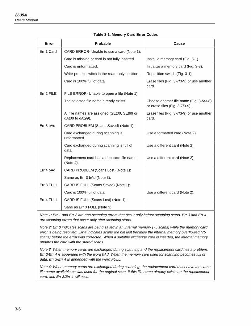
2635AUsers Manual
3-6
Table 3-1. Memory Card Error Codes
Error Probable Cause
Err 1 Card CARD ERROR- Unable to use a card (Note 1):
Card is missing or card is not fully inserted. Install a memory card (Fig. 3-1).
Card is unformatted. Initialize a memory card (Fig. 3-3).
Write-protect switch in the read -only position. Reposition switch (Fig. 3-1).
Card is 100% full of data Erase files (Fig. 3-7/3-9) or use anothercard.
Err 2 FILE FILE ERROR- Unable to open a file (Note 1):
The selected file name already exists. Choose another file name (Fig. 3-5/3-8)or erase files (Fig. 3-7/3-9).
All file names are assigned (SEt00, SEt99 ordAt00 to dAt99).
Erase files (Fig. 3-7/3-9) or use anothercard.
Err 3 bAd CARD PROBLEM (Scans Saved) (Note 1):
Card exchanged during scanning isunformatted.
Use a formatted card (Note 2).
Card exchanged during scanning is full ofdata.
Use a different card (Note 2).
Replacement card has a duplicate file name.(Note 4).
Use a different card (Note 2).
Err 4 bAd CARD PROBLEM (Scans Lost) (Note 1):
Same as Err 3 bAd (Note 3).
Err 3 FULL CARD IS FULL (Scans Saved) (Note 1):
Card is 100% full of data. Use a different card (Note 2).
Err 4 FULL CARD IS FULL (Scans Lost) (Note 1):
Sane as Err 3 FULL (Note 3)
Note 1: Err 1 and Err 2 are non-scanning errors that occur only before scanning starts. Err 3 and Err 4are scanning errors that occur only after scanning starts.
Note 2: Err 3 indicates scans are being saved in an internal memory (75 scans) while the memory carderror is being resolved. Err 4 indicates scans are bin lost because the internal memory overflowed (75scans) before the error was corrected. When a suitable exchange card is inserted, the internal memoryupdates the card with the stored scans.
Note 3: When memory cards are exchanged during scanning and the replacement card has a problem,Err 3/Err 4 is appended with the word bAd. When the memory card used for scanning becomes full ofdata, Err 3/Err 4 is appended with the word FULL.
Note 4: When memory cards are exchanged during scanning, the replacement card must have the samefile name available as was used for the original scan. If this file name already exists on the replacementcard, and Err 3/Err 4 will occur.

Memory Card OperationsInitializing a Memory Card 3
3-7
Initializing a Memory CardPerform the procedure in Figure 3-3 to initialize (format) a memory card. Memory cardscan also be formatted at a PC if it is equipped with a memory card reader. (Formatting ata PC uses the format utility supplied with the memory card reader.)When the memorycard is formatted, a standard DOS file system and directory are put into the memory onthe card. To exit at any time (formatting not completed), press the C key.
NoteAny scan data that may be stored in the internal memory waiting to bewritten to a valid memory card (see paragraph 3-8 Changing the MemoryCard During Scanning) will be lost when formatting a memory card.
InitStAtdirdAtASEtUP
FILES
ENTER
yESno
Init
ENTER
Selecting the INITIALIZATION mode. Insert the memory card to be initialized. Press the FILES key to access the FILES menu. Press the up/down arrow keys until Init is displayed, then press the ENTER key. The menu changes to Init. If an error message appears, see Table 3-1.
Verifing the INIT mode. To verify the selection of the initialization mode, press the up/down arrow keys until yES is displayed in the Init menu, then press the ENTER key. To exit the procedure, select no and then press the ENTER key. If yES is selected, the menu changes to SUrE.
Typical
Required
yESno
SUrE
ENTER
Initializating the memory card. Press the up/down arrow keys to select yES or no in the SUrE menu, then press the ENTER key. "yES" will initialize the memory card, erasing all previous data (if any); "no" cancels the procedure. If Err 1 CArd appears, the small switch on the card may be in the write-protect position. Reposition the switch and repeat this procedure.
FILES
op39f.eps
Figure 3-3. Initializing a Memory Card
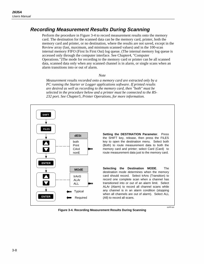
2635AUsers Manual
3-8
Recording Measurement Results During ScanningPerform the procedure in Figure 3-4 to record measurement results onto the memorycard. The destination for the scanned data can be the memory card, printer, both thememory card and printer, or no destination, where the results are not saved, except in theReview array (last, maximum, and minimum scanned values) and in the 100-scaninternal memory FIFO (First In First Out) log queue. (The internal memory log queue isaccessed only through the computer interface. See Chapter4, "ComputerOperations.")The mode for recording to the memory card or printer can be all scanneddata, scanned data only when any scanned channel is in alarm, or single scans when analarm transitions into or out of alarm.
NoteMeasurement results recorded onto a memory card are extracted only by aPC running the Starter or Logger applications software. If printed resultsare desired as well as recording to the memory card, then "both" must beselected in the procedure below and a printer must be connected to the RS-232 port. See Chapter5, Printer Operations, for more information.
MOdE
trAnSALArALL
Selecting the Destination MODE. The destination mode determines when the memory card should record. Select trAns (Transition) to record one complete scan when a channel has transitioned into or out of an alarm limit. Select ALAr (Alarm) to record all channel scans while any channel is in an alarm condition (stopping when all channels are out of alarm). Select ALL (All) to record all scans.
dESt
bothPrintCArdnonE
SHIFT
FILES
ENTER
Setting the DESTINATION Parameter. Press the SHIFT key, release, then press the FILES key to open the destination menu. Select both (Both) to route measurement data to both the memory card and printer; select Card (Card) to route measurement data just to the memory card.
Typical
RequiredENTER
op40f.eps
Figure 3-4. Recording Measurement Results During Scanning

Memory Card OperationsSetup File Procedures 3
3-9
Setup File ProceduresPerform the following procedures to LOAD, STORE, and ERASE memory cardinstrument configuration (SEtUP) files.
Using Setup StorePerform the procedure in Figure 3-5 to save the current instrument configuration. Thecommunication parameters: baud, parity, CTS, and echo, remain as set previously by thefront panel controls or computer interface. The instrument automatically assigns the nextsequential SEtxx file name. When SEt99 is reached, the instrument loops back to reusepreviously assigned file names that have been erased or skipped over. To assign yourown file name, use the up/down and left/right arrow keys when creating the file.
FILES
ENTER
SEtUP
StorE
ENTER
ENTER
Typical
Required
Selecting the SETUP mode. Press the FILES key to access the FILES menu. Press the up/down arrow keys until SEtUP is displayed, then press the ENTER key. The menu changes to SEtUP. If an error message appears, see Table 3-1.
Selecting the STORE mode. Press the up/down arrow keys until StorE is displayed in the SEtUP menu, then press the ENTER key. The menu changes to StorE and a file name is displayed.
Storing a SEtxx File. Record the displayed SEtxx file name, where xx represents an instrument-assigned number between 00 and 99 or use the up/down, left/right arrow keys to select the xx number. Press the ENTER key to store the file.
InitStAtdirdAtASEtUP
ErASEStorELOAd
SEt99SEtxxSEt00
yESno
SUrE
Overwriting a SEtxx File. If the xx number selected in the previous step is already assigned, the existing file will be overwritten with the new file. If this is desired, select yES then press the ENTER key. If no is selected, the procedure will terminate. If an error message appears, see Table 3-1.
FILES
ENTER
op41f.eps
Figure 3-5. Using SETUP STORE to Save Configuration Files
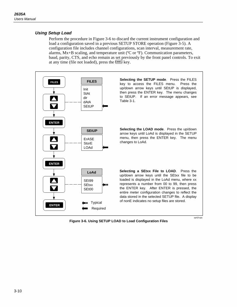
2635AUsers Manual
3-10
Using Setup LoadPerform the procedure in Figure 3-6 to discard the current instrument configuration andload a configuration saved in a previous SETUP STORE operation (Figure 3-5). Aconfiguration file includes channel configurations, scan interval, measurement rate,alarms, Mx+B scaling, and temperature unit (ºC or ºF). Communication parameters,baud, parity, CTS, and echo remain as set previously by the front panel controls. To exitat any time (file not loaded), press the C key.
Typical
Required
FILES
ENTER
ErASEStorELOAd
SEtUP
SEt99SEtxxSEt00
LoAd
ENTER
ENTER
Selecting the SETUP mode. Press the FILES key to access the FILES menu. Press the up/down arrow keys until SEtUP is displayed, then press the ENTER key. The menu changes to SEtUP. If an error message appears, see Table 3-1.
Selecting the LOAD mode. Press the up/down arrow keys until LoAd is displayed in the SETUP menu, then press the ENTER key. The menu changes to LoAd.
Selecting a SEtxx File to LOAD. Press the up/down arrow keys until the SEtxx file to be loaded is displayed in the LoAd menu, where xx represents a number from 00 to 99, then press the ENTER key. After ENTER is pressed, the entire meter configuration changes to reflect the data stored in the selected SETUP file. A display of nonE indicates no setup files are stored.
InitStAtdirdAtASEtUP
FILES
op42f.eps
Figure 3-6. Using SETUP LOAD to Load Configuration Files

Memory Card OperationsSetup File Procedures 3
3-11
Using Setup ErasePerform the procedure in Figure 3-7 to remove a setup file from the memory card.Removing a file does not interrupt the sequential SEtxx file names assigned with theSEtUP STORE command. When SEt99 is reached, the instrument loops back to reusepreviously assigned file names that have been erased or skipped over. To exit at any time(file not erased), press the C key.
FILES
ENTER
SEtUP
SEt99SEtxxSEt00
ErASE
ENTER
ENTER
Selecting the SETUP mode. Press the FILES key to access the FILES menu. Press the up/down arrow keys until SEtUP is displayed, then press the ENTER key. The menu changes to SEtUP. If an error message appears, see Table 3-1.
Selecting the ERASE mode. Press the up/down arrow keys until ErASE is displayed in the SEtUP menu, then press the ENTER key. The menu changes to ErASE.
Selecting a SEtxx File to ERASE. Press the up/down arrow keys until the SEtxx file to be erased is displayed in the ErASE menu, where xx represents a number from 00 to 99, then press the ENTER key. The menu changes to SUrE.
Typical
Required
yESno
SUrE
ENTER
Erasing a SEtxx File. Press the up/down arrow keys to select yES or no in the SUrE menu, then press the ENTER key. yES will erase the file, no will cancel the procedure and nothing will be erased. The procedure repeats after pressing ENTER, or displays nonE if there are no files to erase. Press the CANCL key to exit. If an error message occurs, see Table 3-1.
FILES
InitStAtdirdAtASEtUP
ErASEStorELOAd
op43f.eps
Figure 3-7. Using SETUP ERASE to Delete Configuration Files

2635AUsers Manual
3-12
Data File ProceduresPerform the following procedures to OPEN, LOAD, STORE, and ERASE memory cardinstrument data (DATA) files.
Using Data OpenPerform the procedure in Figure 3-8 to open a data file in preparation for recordingmeasurement data to the memory card. This procedure is automatically invoked if theQ key is pressed and the instrument is configured for memory card operations. Theinstrument automatically assigns the next sequential dAtxx file name. To assign yourown file name, use the up/down and left/right arrow keys when creating the file. WhendAt99 is reached, the instrument loops back to reuse previously assigned file names thathave been erased or skipped over. Data cannot be appended to an existing file, except inthe case where scanning is turned off and on without changing the instrumentconfiguration. Before using the DATA OPEN command, verify the instrument isconfigured for measurement. If a file is opened and then the instrument configuration ischanged, the file will automatically be closed.
FILES
ENTER
ErASEOPEn
dAtA
dAt99dAtxxdAt00
OPEn
ENTER
Typical
Required
Selecting the DATA mode. Press the FILES key to access the FILES menu. Press the up/down arrow keys until dAtA is displayed, then press the ENTER key. The menu changes to dAtA. If an error message appears, refer to Table 3-1.
Selecting the OPEN mode. Press the up/down arrow keys until OPEn is displayed in the dAtA menu, then press the ENTER key. The menu changes to OPEn and a file name is displayed.
Opening a dAtxx File. Record the displayed dAtxx file name, where xx represents an instrument-assigned number from 00 to 99. Or use the up/down, left/rightarrow keys to select the xx number. Press the ENTER key to open the file. If an error message appears, see Table 3-1.
The "dESt" menu appears if a dAtxx file is opened and the memory card is not selected as a data destination (see Figure 3-4).
InitStAtdirdAtASEtUP
FILES
ENTER
op44f.eps
Figure 3-8. Using DATA OPEN to Save Measurement Data in a File

Memory Card OperationsData File Procedures 3
3-13
Using Data ErasePerform the procedure in Figure 3-9 to remove a data file from the memory card.Removing a file does not interrupt the sequential dAtxx file names assigned with theDATA OPEN command. When dAt99 is reached, the instrument will loop back andreuse previously assigned file names that have been erased or skipped over. To exit atany time (file not erased), press the C key.
FILES
ENTER
ErASEOPEn
dAtA
dAt99dAtxxdAt00
ErASE
ENTER
ENTER
Selecting the DATA mode. Press the FILES key to access the FILES menu. Press the up/down arrow keys until dAtA is displayed, then press the ENTER key. The menu changes to dAtA. If an error message appears, see Table 3-1.
Selecting the ERASE mode. Press the up/down arrow keys until ERASE is displayed in the dAtA menu, then press the ENTER key. The menu changes to ErASE.
Selecting a dAtxx File to ERASE. Press the up/down arrow keys until the dAtxx file to be erased is displayed in the ErASE menu, where xx represents a number from 00 to 99, then press the ENTER key. The menu changes to SUrE.
Typical
Required
yESno
SUrE
ENTER
Erasing a dAtxx File. Press the up/down arrow keys to select yES or no in the SUrE menu, then press the ENTER key. yES will erase the file; no will cancel the procedure and nothing will be erased. The procedure repeats after pressing ENTER, or displays nonE if there are no files to erase. Press the CANCL key to exit. If an error message occurs, see Table 3-1.
FILES
InitStAtdirdAtASEtUP
op45f.eps
Figure 3-9. Using DATA ERASE to Delete a Measurement Data File
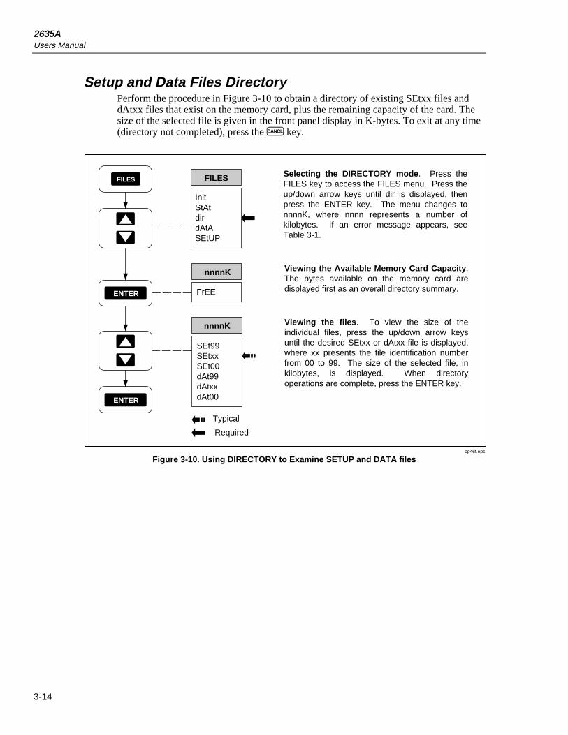
2635AUsers Manual
3-14
Setup and Data Files DirectoryPerform the procedure in Figure 3-10 to obtain a directory of existing SEtxx files anddAtxx files that exist on the memory card, plus the remaining capacity of the card. Thesize of the selected file is given in the front panel display in K-bytes. To exit at any time(directory not completed), press the C key.
FILES
ENTER
SEt99SEtxxSEt00dAt99dAtxxdAt00
nnnnK
ENTER
Selecting the DIRECTORY mode. Press the FILES key to access the FILES menu. Press the up/down arrow keys until dir is displayed, then press the ENTER key. The menu changes to nnnnK, where nnnn represents a number of kilobytes. If an error message appears, see Table 3-1.
Viewing the files. To view the size of the individual files, press the up/down arrow keys until the desired SEtxx or dAtxx file is displayed, where xx presents the file identification number from 00 to 99. The size of the selected file, in kilobytes, is displayed. When directory operations are complete, press the ENTER key.
Typical
Required
FILES
FrEE
nnnnK
InitStAtdirdAtASEtUP
Viewing the Available Memory Card Capacity. The bytes available on the memory card are displayed first as an overall directory summary.
op46f.eps
Figure 3-10. Using DIRECTORY to Examine SETUP and DATA files
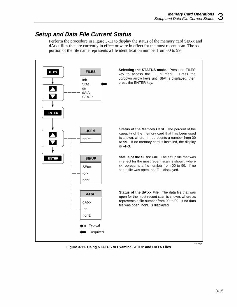
Memory Card OperationsSetup and Data File Current Status 3
3-15
Setup and Data File Current StatusPerform the procedure in Figure 3-11 to display the status of the memory card SEtxx anddAtxx files that are currently in effect or were in effect for the most recent scan. The xxportion of the file name represents a file identification number from 00 to 99.
InitStAtdirdAtASEtUP
FILES
ENTER
dAtxx
-or-
nonE
dAtA
ENTER
Selecting the STATUS mode. Press the FILES key to access the FILES menu. Press the up/down arrow keys until StAt is displayed, then press the ENTER key.
Status of the dAtxx File. The data file that was open for the most recent scan is shown, where xx represents a file number from 00 to 99. If no data file was open, nonE is displayed.
Typical
Required
SEtxx
-or-
nonE
SEtUP
nnPct
USEd
Status of the SEtxx File. The setup file that was in effect for the most recent scan is shown, where xx represents a file number from 00 to 99. If no setup file was open, nonE is displayed.
Status of the Memory Card. The percent of the capacity of the memory card that has been used is shown, where nn represents a number from 00 to 99. If no memory card is installed, the display is --Pct.
FILES
op47f.eps
Figure 3-11. Using STATUS to Examine SETUP and DATA Files

2635AUsers Manual
3-16
Memory Card File Operations to and from a PCAll memory card file transfers to and from the instrument are controlled at the PC.Nothing is required at the instrument end, except to have the RS-232 link operatingcorrectly (see Chapter4, "Computer Operations") and having the desired memory cardinstalled in the instrument front panel. Refer to the applications software documentationsupplied with Starter (supplied) or Logger (optional).

4-1
Chapter 4Computer Operations
Title Page
Summary of Computer Operations.................................................................... 4-3Connecting the Instrument to a PC.................................................................... 4-3Configuring the Instrument for Computer Operations ...................................... 4-5Configuring the PC for Computer Operations .................................................. 4-6Testing the Instrument/PC RS-232 Interface .................................................... 4-6
Testing the RS-232 Interface Using Terminal Emulation (Windows) ......... 4-6Testing the RS-232 Interface Using Terminal Emulation (Generic) ............ 4-7Testing the RS-232 Interface Using Gwbasic............................................... 4-9Testing the RS-232 Interface Using Qbasic.................................................. 4-10
Computer Interface Commands and Operation ................................................. 4-12How the Instrument Processes Input............................................................. 4-12Input Terminators.......................................................................................... 4-12Input String Examples................................................................................... 4-13Sending Numeric Values to the Instrument .................................................. 4-13How the Instrument Processes Output .......................................................... 4-13Status Registers ............................................................................................. 4-14
Instrument Event Register (IER) .............................................................. 4-14Standard Event Status Register (ESR)...................................................... 4-16Status Byte Register (STB)....................................................................... 4-17
Computer Interface Command Set................................................................ 4-18Xmodem File Transfers ................................................................................ 4-18

2635AUsers Manual
4-2
FUNC ALRM
Mx+B CANCEL ENTER
RATE
INTVL FILES REVIEW
SHIFT LIST TOTAL
SINGLE
TRIGS
SCAN
MON
CLOCK MODE CLEAR
LOCAL COMM ZERO
mAmVDCAC
k Hz
REVIEWLASTHYDRA DATA BUCKET
300VMAX
COM V
M
CH
BUSY BATT
op82f.eps
Computer OperationsSummary of Computer Operations 4
4-3
Summary of Computer OperationsComputer operations allow the instrument to be configured and controlled from apersonal computer (PC), including data exchanges with the instrument memory card.The computer interface is via an RS-232 link between the instrument RS-232 port and aPC serial COM port. The PC gives operation and configuration commands to theinstrument, and the instrument returns status signals (alarms, for example) and scanmeasurement data. PC operations can be in real time with a dedicated RS-232connection, or the instrument can be connected to a PC for configuration and thenremoved for distant operations. Memory Card features are described in Chapter 3,Memory Card Operations.
PC applications software Hydra Series II Starter Package (Starter) and Hydra Series IILogger Package (Logger) (optional) operate the RS-232 computer interface. Thesoftware packages are described in separate technical manuals; however, eachaccomplishes the following:
Starter (supplied) Starter is a menu-driven software package used to transferconfiguration data from and to the instrument, log measurement datacollected by the instrument, and manage the acquired data.
Logger (optional)configuration
Hydra Series II Logger is an optional full featured Windows basedand data logging package. It can communicate with two Hydras atonce and can also utilize telephone modems for remoteapplications. A brochure with complete details is available.
Custom software can be developed by the user in GWBASIC, Quick BASIC (QBASIC),or Quick C using the computer interface command set, which is described in thischapter.
The RS-232 computer interface between a instrument and a PC is discussed in thefollowing paragraphs in this sequence:
• Connecting the Instrument to a PC
• Configuring the Instrument for Computer Operations
• Configuring the PC for Computer Operations
• Testing the Instrument/PC RS-232 Interface
• Computer Interface Commands and Operation
Connecting the Instrument to a PCThe two most common configurations for connecting the instrument to a PC are shownin Figure 4-1. The instrument RS-232 port (DB-9 connector) is cabled to a PC serialCOM port that uses either a DB-9 connector or DB-25 connector. The connecting cablecan be fabricated (see Appendix D) or ordered from Fluke as an option (see Chapter 1).

2635AUsers Manual
4-4
RS-232(DB-9)(MALE)
COM PORT(DB-9)(MALE)
FLUKE R543 CABLE(OR EQUAL)
PC CONNECTIONWITH DB-9
CONNECTOR
RS-232(DB-9)(MALE)
COM PORT(DB-25)(MALE)
FLUKE RS40 CABLE(OR EQUAL)
PC CONNECTIONWITH DB-25
CONNECTORHYDRA
PC
HYDRA
PC
op48f.eps
Figure 4-1. Connecting the Instrument to a PC
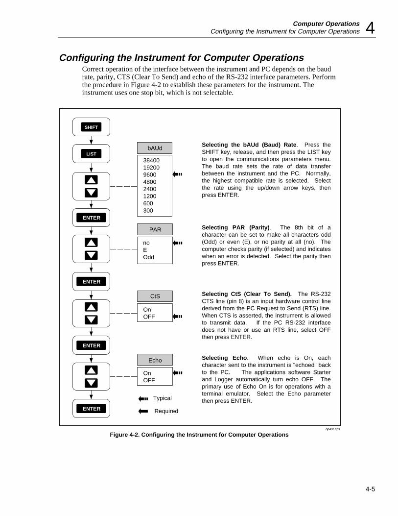
Computer OperationsConfiguring the Instrument for Computer Operations 4
4-5
Configuring the Instrument for Computer OperationsCorrect operation of the interface between the instrument and PC depends on the baudrate, parity, CTS (Clear To Send) and echo of the RS-232 interface parameters. Performthe procedure in Figure 4-2 to establish these parameters for the instrument. Theinstrument uses one stop bit, which is not selectable.
SHIFT
LIST38400192009600480024001200600300
bAUd
ENTER
ENTER
PAR
noEOdd
ENTER
Echo
OnOFF
CtS
OnOFF
ENTER
Typical
Required
Selecting the bAUd (Baud) Rate. Press the SHIFT key, release, and then press the LIST key to open the communications parameters menu. The baud rate sets the rate of data transfer between the instrument and the PC. Normally, the highest compatible rate is selected. Select the rate using the up/down arrow keys, then press ENTER.
Selecting PAR (Parity). The 8th bit of a character can be set to make all characters odd (Odd) or even (E), or no parity at all (no). The computer checks parity (if selected) and indicates when an error is detected. Select the parity then press ENTER.
Selecting CtS (Clear To Send). The RS-232 CTS line (pin 8) is an input hardware control line derived from the PC Request to Send (RTS) line. When CTS is asserted, the instrument is allowed to transmit data. If the PC RS-232 interface does not have or use an RTS line, select OFF then press ENTER.
Selecting Echo. When echo is On, each character sent to the instrument is "echoed" back to the PC. The applications software Starter and Logger automatically turn echo OFF. The primary use of Echo On is for operations with a terminal emulator. Select the Echo parameter then press ENTER.
op49f.eps
Figure 4-2. Configuring the Instrument for Computer Operations

2635AUsers Manual
4-6
Configuring the PC for Computer OperationsOperation of the instrument from a PC always involves software, either softwaresupplied with the instrument (Starter) or software developed by the user (GWBASIC,QBASIC or Quick C). Since the PC COM port is set up by the operating software, thereis no separate configuration procedure.
Testing the Instrument/PC RS-232 InterfaceThe RS-232 link between the instrument and PC should be tested before it is used forcommunications. Since DOS commands cannot test the link, some form of softwarecontrol is required. Four procedures are provided:
• Testing using terminal emulation (Windows)
• Testing using terminal emulation (Generic)
• Testing using commands while in GWBASIC
• Testing using commands while in QBASIC
The RS-232 computer interface can also be tested using the TERM (Terminal) mode inboth Starter and Logger applications software. Refer to the technical manuals suppliedwith the software for the test procedures.
Testing the RS-232 Interface Using Terminal Emulation (Windows)Complete the procedure below to test the RS-232 link between the PC and instrumentusing the PC Windows terminal emulator. Identify the PC COM port used for the RS-232 link (COM1 is assumed).
1. Configure the Data Bucket communication parameters, as described in Figure 4-2,for bAUd = 9600, PAR = no, CtS = OFF, and Echo = On.
2. Turn on the PC, start Windows, open the Accessories menu and select Terminal.
3. Open the Terminal Settings menu and select Communications.
4. In Communications, select the following, then use OK to exit to Terminal:
Connector COM1 [Typical]
Baud Rate 9600
Data Bits 8
Stop Bits 1
Parity None
Flow ControlNone
5. In Terminal, request the Data Bucket to send its identification number by entering:*IDN? <Enter>. If *IDN? did not appear on the screen as the characters wereentered, be sure the instrument RS-232 port is configured for Echo = On (Figure 4-2). If the wrong characters appear, there is an incompatibility in the COM portconfigurations (baud rate, parity, etc.). If everything seems normal, but charactersstill don’t appear, check the RS-232 connection cable (see Appendix D). When theRS-232 link is operating correctly, the instrument returns an identification string andexecution prompt similar to the following:
FLUKE,2635A,0,Mn.n An.n Dn.n Ln.n
=>
Computer OperationsTesting the Instrument/PC RS-232 Interface 4
4-7
Mn.n identifies the main software version.
An.n identifies the analog-to-digital converter software version.
Dn.n identifies the display software version.
Ln.n identifies the programmable gate-array configuration version.
6. Other commands can be entered from the PC to gain familiarity with the instrumentcommand set. All commands are summarized in Table 4-4 and explained in Table 4-5.
For example: to reset the instrument, configure channel 0 to measure volts dc usingthe 300V DC scale (scale 4), send scan results to the RS-232 port, and scan once,enter the following:
*RST[Resets the instrument (which does not affect the communication parameters)]
=>
FUNC 0, VDC, 4[Set channel 0 to volts dc and scale 4 (300V DC)]
=>
PRINT_TYPE 0,0[Sets the data destination as the RS-232 port, and all data]
=>
PRINT 1[Enables data logging to the RS-232 port]
=>
*TRG [Triggers a single scan]
=>
15:17:0407/21/94
0:000.00 VDC
ALM:15DIO:255TOTAL:0
To decode the printout, see Figure 5-3.
The commands in the above example can be combined into a single entry by usingthe semicolon separator character:
*RST;FUNC 0,VDC,4;PRINT_TYPE 0,0;PRINT 1;*TRG.
7. One of the following three possible prompts are returned when a command is sent tothe instrument:
=> The command was executed[Example, PRINT 1].
!> The command was recognized, but not executed [Example, PRINT 3, where onlyPRINT 0 and PRINT 1 are legal entries].
?> The command wasn’t recognized [Example, PRITN 1, spelling error].
8. Exit Windows and return to DOS, as required.
Testing the RS-232 Interface Using Terminal Emulation (Generic)Complete the procedure below to test the RS-232 link between the PC and instrumentusing a generic terminal emulator. Refer to the documentation appropriate to the selectedcommunications/terminal emulation software, as required. Identify the PC COM portused for the RS-232 link (COM1 is assumed).
2635AUsers Manual
4-8
1. Configure the Data Bucket communication parameters, as described in Figure 4-2,for bAUd = 9600, PAR = no, CtS = OFF, and Echo = On.
2. Turn on the PC, start the communications software, and open the COM portconfiguration screen.
3. Select the following communications parameters
Connector COM1 [Typical]
Baud Rate 9600
Data Bits 8
Stop Bits 1
Parity None
Flow ControlNone[May be called the RTS/CTS line]
4. In Terminal, request the Data Bucket to send its identification number by entering:*IDN? <Enter>. If *IDN? did not appear on the screen as the characters wereentered, be sure the instrument RS-232 port is configured for Echo = On (Figure 4-2). If the wrong characters appear, there is an incompatibility in the COM portconfigurations (baud rate, parity, etc.). If everything seems normal, but charactersstill don’t appear, check the RS-232 connection cable (see Appendix D). When theRS-232 link is operating correctly, the instrument returns an identification string andexecution prompt similar to the following:
FLUKE,2635A,0,Mn.n An.n Dn.n Ln.n
=>
Mn.n identifies the main software version.
An.n identifies the analog-to-digital converter software version.
Dn.n identifies the display software version.
Ln.n identifies the programmable gate-array configuration version.
5. Other commands can be entered from the PC to gain familiarity with the instrumentcommand set. All commands are summarized in Table 4-4 and explained in Table 4-5.
For example: to reset the instrument, configure channel 0 to measure volts dc usingthe 300V DC scale (scale 4), send scan results to the RS-232 port, and scan once,enter the following:
*RST [Resets the instrument (which does not affect the communication parameters)]
=>
FUNC 0, VDC, 4 [Set channel 0 to volts dc and scale 4 (300V DC)]
=>
PRINT_TYPE 0,0 [Sets the data destination as the RS-232 port, and all data]
=>
PRINT 1 [Enables data logging to the RS-232 port]*TRG [Triggers a single scan]
=>
15:17:04 07/21/94
0: 000.00 VDC

Computer OperationsTesting the Instrument/PC RS-232 Interface 4
4-9
ALM:15 DIO:255 TOTAL:0
To decode the printout, see Figure 5-3.
The commands in the above example can be combined into a single entry by usingthe semicolon separator character:
*RST;FUNC 0,VDC,4;PRINT_TYPE 0,0;PRINT 1;*TRG.
6. One of the following three possible prompts are returned when a command is sent tothe instrument:
=> The command was executed [Example, PRINT 1].
!> The command was recognized, but not executed [Example, PRINT 3, where only PRINT 0 and PRINT 1 are legal entries].
?> The command wasn’t recognized [Example, PRITN 1, spelling error].
7. Exit the communications program and return to DOS, as required.
Testing the RS-232 Interface Using GwbasicComplete the procedure below to test the RS-232 link between the PC and instrumentusing GWBASIC interpreter commands. Identify the PC COM port used for the RS-232link (COM1 is assumed).
1. Configure the Data Bucket communication parameters, as described in Figure 4-2,for bAUd = 9600, PAR = no, CtS = OFF, and Echo = On.
2. Turn on the PC and enter GWBASIC to start the BASIC interpreter.
3. With the entry screen displayed, enter the following commands (which are executedimmediately). The last command returns an identification string and executionprompt:
OPEN "COM1,9600,N,8,1,CS,CD" FOR RANDOM AS #1
OK
PRINT #1, "*IDN?"
OK
PRINT INPUT$ (46, #1)
IDN?
FLUKE,2635A,0,Mn.n An.n Dn.n Ln.n
=>
Mn.n identifies the main software version.
An.n identifies the analog-to-digital converter software version.
Dn.n identifies the display software version.
Ln.n identifies the programmable gate-array configuration version.
If the identification string was not returned, be sure the instrument RS-232 port isconfigured for Echo = On (Figure 4-2). Verify that the commands were exact. Forexample, entering PRINT #1, "*IDN" instead of PRINT #1, "*IDN?" will hang upthe program. Press <CNTL><BREAK> to escape, then re-enter the commands. Ifthe wrong characters appear, there is an incompatibility in the COM portconfigurations (baud rate, parity, etc.). If everything seems normal, but charactersstill don’t appear, check the RS-232 connection cable (see Appendix D).

2635AUsers Manual
4-10
One of the following three possible prompts are returned when a command is sent tothe instrument:
=> The command was executed [Example, PRINT 1].
!> The command was recognized, but not executed [Example, PRINT 3, where only PRINT 0 and PRINT 1 are legal entries].
?> The command wasn’t recognized [Example, PRITN 1, spelling error].
4. Other commands can be entered from the PC to gain familiarity with the instrumentcommand set. All commands are summarized in Table 4-4 and explained in Table 4-5. For example: to reset the instrument, configure channel 0 to measure volts dcusing the 300V DC scale (scale 4), send scan results to the RS-232 port, and scanonce, enter the following [only the output of the last command is shown]:
PRINT #1, "*RST":PRINT INPUT$(10, #1)
PRINT #1, "FUNC 0, VDC,4":PRINT INPUT$(18, #1)
PRINT #1, "PRINT_TYPE 0,0":PRINT INPUT$(20, #1)
PRINT #1, "PRINT 1":PRINT INPUT$(13, #1)
PRINT #1, "*TRG":PRINT INPUT$(83, #1)
15:17:0407/21/94
0:000.00 VDC
ALM:15DIO:255TOTAL:0
To decode the printout, see Figure 5-3.
The commands in the above example can be combined into a single entry by usingthe semicolon separator character:
PRINT #1, "*RST;FUNC 0,VDC,4;PRINT_TYPE 0,0;PRINT 1;*TRG":PRINTINPUT$(124, #1)
If other commands are entered, remember that the input character count xxx forPRINT INPUT$(xxx, #1) command must be exact. A number too small will not readall the characters and will leave residual characters in the buffer, while a number toobig will "hang up" the command until more characters are loaded into the buffer or<CNTL><BREAK> is pressed, which erases the buffer.
5. Enter SYSTEM to exit GWBASIC and return to DOS.
Testing the RS-232 Interface Using QbasicComplete the procedure below to test the RS-232 link between the PC and instrumentusing QBASIC compiler commands. Identify the PC COM port used for the RS-232 link(COM1 is assumed).
1. Configure the Data Bucket communication parameters, as described in Figure 4-2,for bAUd = 9600, PAR = no, CtS = OFF, and Echo = On.
2. Turn on the PC and enter QBASIC to start the BASIC compiler.
3. With the entry screen displayed, enter the following commands (which are notexecuted immediately):
OPEN "COM1,9600,N,8,1,CS,CD" FOR RANDOM AS #1
PRINT #1, "*IDN?"

Computer OperationsTesting the Instrument/PC RS-232 Interface 4
4-11
PRINT INPUT$(46, #1)
4. Enter SHIFT<F5> to run the program entered in step 3.If the RS-232 interface isoperating correctly, the instrument returns an identification string and executionprompt similar to the following:
*IDN?
FLUKE,2635A,0,Mn.n An.n Dn.n Ln.n
=>
Mn.n identifies the main software version.
An.n identifies the analog-to-digital converter software version.
Dn.n identifies the display software version.
Ln.n identifies the programmable gate-array configuration version.
If the identification string was not returned, be sure the instrument RS-232 port isconfigured for Echo = On (Figure 4-2). Verify that the commands were exact. Forexample, entering PRINT #1, "*IDN" instead of PRINT #1, "*IDN?" will hang upthe program. Press <CNTL><BREAK> to escape, then re-enter the commands. Ifthe wrong characters appear, there is an incompatibility in the COM portconfigurations (baud rate, parity, etc.). If everything seems normal, but charactersstill don’t appear, check the RS-232 connection cable (see Appendix D).
One of the following three possible prompts are returned when a command is sent tothe instrument:
=> The command was executed [Example, PRINT 1].
!> The command was recognized, but not executed [Example, PRINT 3, where only PRINT 0 and PRINT 1 are legal entries].
?> The command wasn’t recognized [Example, PRITN 1, spelling error].
5. Other commands can be entered from the PC to gain familiarity with the instrumentcommand set. All commands are summarized in Table 4-4 and explained in Table 4-5. For example: to reset the instrument, configure channel 0 to measure volts dcusing the 300V DC scale (scale 4), send scan results to the RS-232 port, and scanonce, enter the following, then enter SHIFT<F5> to run [only the output of the lastcommand is shown]:
PRINT #1, "*RST":PRINT INPUT$(10, #1)
PRINT #1, "FUNC 0, VDC,4":PRINT INPUT$(18, #1)
PRINT #1, "PRINT_TYPE 0,0":PRINT INPUT$(20, #1)
PRINT #1, "PRINT 1":PRINT INPUT$(13, #1)
PRINT #1, "*TRG":PRINT INPUT$(83, #1)
15:17:0407/21/94
0:000.00 VDC
ALM:15DIO:255TOTAL:0
To decode the printout, see Figure 5-3.
The commands in the above example can be combined into a single entry by usingthe semicolon separator character:

2635AUsers Manual
4-12
PRINT #1, "*RST;FUNC 0,VDC,4;PRINT_TYPE 0,0;PRINT 1;*TRG":PRINTINPUT$(124, #1)
If other commands are entered, remember that the input character count xxx forPRINT INPUT$(xxx, #1) command must be exact. A number too small willnot read all the characters and will leave residual characters in the buffer, while anumber too big will "hang up" the command until more characters are loaded intothe buffer or <CNTL><BREAK> is pressed, which erases the buffer.
6. Use Exit to exit QBASIC and return to DOS.
Computer Interface Commands and OperationOperation of the computer interface between the instrument and PC normally involvesthe application software Starter (supplied) and Logger (optional), described in separatemanuals. This chapter is provided for the user who wishes to develop his own softwareinterface using the instrument command set. The topics in this chapter include:
• How the Instrument Processes Input
• Input Terminators
• Input String Examples
• Sending Numeric Values to the instrument
• How the Instrument Processes Output
• Status Registers
• Computer Interface Command Set
How the Instrument Processes InputThe instrument processes and executes valid input character strings from the hostpersonal computer (PC). A valid input string is one or more syntactically correctcommands, separated by semicolons (;) followed by an input terminator. The instrumentstores received inputs in a 350-byte buffer. When an input string is received, it is notexecuted or checked for proper syntax until the input terminator is received. If the 350-byte input buffer becomes full, a device-dependent error prompt is returned, and furtherinputs to the string are ignored, except for a termination character. The instrumentaccepts alphabetic characters in either upper- or lower-case. If a command cannot beunderstood, the command and the rest of the command line are ignored.
Commands must be entered in the correct order as follows:
1. Commands to configure the instrument.
2. Commands that trigger a measurement.
3. Commands to read the results of a triggered measurement.
4. Commands to reconfigure the instrument (if any).
Input TerminatorsAn input terminator is a character sent by the host that identifies the end of a string.When the input terminator is received, the instrument executes all commands enteredsince the last terminator was received, on a first-in, first-out basis. If a communicationserror (e.g., parity, framing, overrun) is detected, a device-dependent error is generated.Valid terminators are LF (line feed), CR (carriage return), CR LF, and LF CR. In some
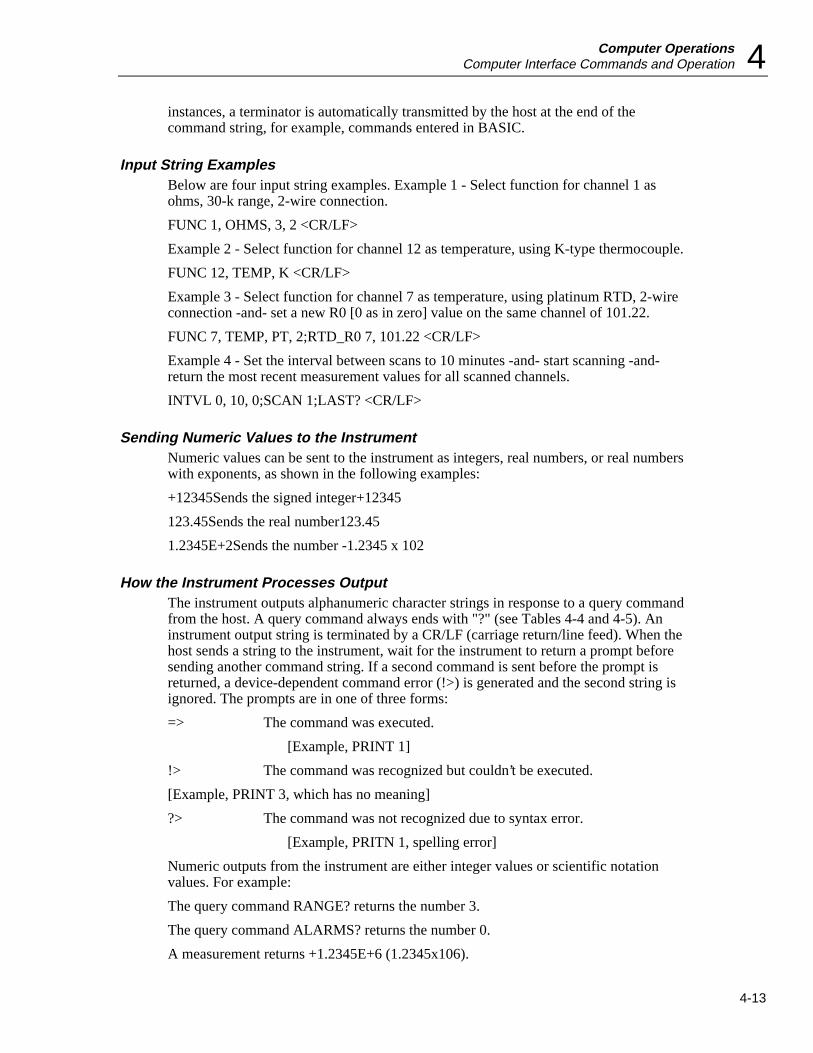
Computer OperationsComputer Interface Commands and Operation 4
4-13
instances, a terminator is automatically transmitted by the host at the end of thecommand string, for example, commands entered in BASIC.
Input String ExamplesBelow are four input string examples. Example 1 - Select function for channel 1 asohms, 30-k range, 2-wire connection.
FUNC 1, OHMS, 3, 2 <CR/LF>
Example 2 - Select function for channel 12 as temperature, using K-type thermocouple.
FUNC 12, TEMP, K <CR/LF>
Example 3 - Select function for channel 7 as temperature, using platinum RTD, 2-wireconnection -and- set a new R0 [0 as in zero] value on the same channel of 101.22.
FUNC 7, TEMP, PT, 2;RTD_R0 7, 101.22 <CR/LF>
Example 4 - Set the interval between scans to 10 minutes -and- start scanning -and-return the most recent measurement values for all scanned channels.
INTVL 0, 10, 0;SCAN 1;LAST? <CR/LF>
Sending Numeric Values to the InstrumentNumeric values can be sent to the instrument as integers, real numbers, or real numberswith exponents, as shown in the following examples:
+12345Sends the signed integer+12345
123.45Sends the real number123.45
1.2345E+2Sends the number -1.2345 x 10²
How the Instrument Processes OutputThe instrument outputs alphanumeric character strings in response to a query commandfrom the host. A query command always ends with "?" (see Tables 4-4 and 4-5). Aninstrument output string is terminated by a CR/LF (carriage return/line feed). When thehost sends a string to the instrument, wait for the instrument to return a prompt beforesending another command string. If a second command is sent before the prompt isreturned, a device-dependent command error (!>) is generated and the second string isignored. The prompts are in one of three forms:
=> The command was executed.
[Example, PRINT 1]
!> The command was recognized but couldn’t be executed.
[Example, PRINT 3, which has no meaning]
?> The command was not recognized due to syntax error.
[Example, PRITN 1, spelling error]
Numeric outputs from the instrument are either integer values or scientific notationvalues. For example:
The query command RANGE? returns the number 3.
The query command ALARMS? returns the number 0.
A measurement returns +1.2345E+6 (1.2345x10⁶).

2635AUsers Manual
4-14
Positive overload (OL on display) returns +001.00E+9
Negative overload (-OL on display) returns -001.00E+9
Open thermocouple (otc on display) returns +009.00E+9
Status RegistersInternal instrument operation is summarized in three data registers, which can beaccessed to determine various events and status conditions before, during, and afterinstrument operation. Each register has a corresponding enable register to enable ormask (disable) any or all data register outputs. The relationship between the threeregisters is shown in Figure 4-3.
Instrument Event Register (IER)The inputs to the Instrument Event Register (IER) include Scan Complete, ConfigurationCorrupted, Calibration Corrupted, Open Thermocouple, Totalize Overflow, and AlarmLimit Transition. Each input is described in Table 4-1. The output byte of the IER isANDed with the output byte of the corresponding Instrument Event Enable Register(IEE). When there is logic high correlation between any of the bits of the IER and IEEregisters, the associated Logical OR gate will output a logic high to the Instrument EventBit (IEB) in the Status Byte Register.

Computer OperationsComputer Interface Commands and Operation 4
4-15
01234567
01234567
Logi
cal O
R
StandardEvent Status
RegisterRead Using *ESR?
(Read ErasesContents)
Power
Transit
ion
Comman
d Erro
r
Execu
tion E
rror
Device
Dep
ende
nt Erro
r
Operat
ion C
omple
te
IEB1237
0123457
&&
&&
&&
&
Logi
cal O
R
Status ByteRegister
Service RequestEnable Register
ESB MAV
Read Using *SRE?Write Using *SRE
Output Queue
QueueNot-Empty
Read Using *STB?
01234567
01234567
Logi
cal O
R
Instrument Event
Register
Read Using IER?(Read Erases
Contents)
InstrumentEvent Enable
Register
Read Using IEE?Write Using IEEE
Scan C
omple
te
Cofigu
ration
Corr
upted
Calibra
tion C
orrup
ted
Open T
herm
ocou
ple
Totalize
Ove
rflow
Alarm Li
mit Tran
sition
MSS(64)
0000000011111111
ESB(32)
0000111100001111
MAV(16)
0011001100110011
IEB(1)
0101010101010101
*STB(DECIMAL)
01161732334849646580819697112113
01234567Standard
Event StatusEnable
Register
Read Using *ESE? Write Using *ESE
01234567Instrument
Event EnableRegister
Read Using IEE?Write Using IEEE
&
&&
&&
&&
&
&
&&
&&
&&
&
MSS
Query
Error
op50f.eps
Figure 4-3. Overview of Status and Event Data Registers

2635AUsers Manual
4-16
For example, an IER byte of binary 10000000 (decimal 128) indicates Scan Complete. Ifthe IEE register is set to binary 10000000 (using the command IEE 128), then a ScanComplete condition will cause the Logical OR gate to output a logic high. In a similarmanner, parameters can be combined. An IER byte of binary 10000101 (decimal 133)and an IEE set to a corresponding binary 10000101 (using the command IEE 133), willcause the Logical OR gate to have a logic high output for any of three conditions: ScanComplete -or- Open Thermocouple -or- Alarm Limit Transition.
Other commands include IER?, which returns the decimal equivalent of the IER byte andthen clears the register to zero, and IEE?, which returns the decimal equivalent of theIEE byte. The command *CLS will clear all event registers. (See Appendix E for an 8-bitbinary-coded-decimal table.)
Table 4-1. Instrument Event Register (IER)
Bit Name Description
0 ALT Alarm Limit Transition. Set high (1) when any measurement value hastransitioned into or out of alarm. Alarms are defined through the frontpanel or the computer interface (ALARM_LIMIT). This bit is cleared whenread with IER? and when alarms or review values are cleared.
1 TOB Totalize Overflow. Set high (1) when the Totalizer overflows (65,535). Thisbit is cleared when read with IER? and when the Totalizer is zeroed fromthe front panel or set to some other non-overflow value (,65,535) with thecomputer interface TOTAL command.
2 OTC Open Thermocouple. Set high (1) when open thermocouple checking isenabled (with TEMP_CONFIG command) and any thermocouple channelis measured with a source impedance greater than 1 to 4 kilohms.
3 CCB Calibration Corrupted. Set high (1) when the instrument calibration data iscorrupted. When a calibration data check shows a corruption of calibrationdata, the calibration alarm bit remains set in the Instrument StatusRegister until the instrument is recalibrated.
4 CNC Configuration Corrupted. the instrument configuration stored in NVRAMhas been found to be corrupted. The RAM CRC is no longer valid.
5,6 not used Always set to 0.
7 SCB Scan Complete. Set high (logic 1) when a measurement scan has beencompleted. This bit is cleared when read with IER?
NOTES
Whenever the Instrument Event Register is read, the condition bits are cleared.
This register is used in conjunction with the Instrument Event Enable Register to determine theconditions under which the Instrument Event Bit of the Status Byte is set.
Standard Event Status Register (ESR)The inputs to the Standard Event Status Register (ESR) include Power On, CommandError, Execution Error, Device Dependent Error, Query Error and Operation Complete.Each input is described in Table 4-2. The output byte of the ESR is ANDed with theoutput byte of the corresponding Standard Event Status Enable (ESE) register. Whenthere is logic high correlation between any of the bits of the ESR and ESE registers, the

Computer OperationsComputer Interface Commands and Operation 4
4-17
associated Logical OR gate will output a logic high to the Event Status Bit (ESB) in theStatus Byte Register.
For example, an ESR byte of binary 00010000 (decimal 16) indicates an ExecutionError. If the ESE register is set to binary 00010000 (using the command *ESE 16), thenan Execution Error condition will cause the Logical OR gate to output a logic high. In asimilar manner, parameters can be combined. An ESR byte of binary 00110000 (decimal48) and an ESE set to a corresponding binary 00110000 (using the command *ESE 48),will cause the Logical OR gate to have a logic high output for any of two conditions:Command Error or Execution Error.
Other commands include *ESR?, which returns the decimal equivalent of the ESR byteand then clears the register to zero, and *ESE?, which returns the decimal equivalent ofthe ESE byte. The command *CLS will clear all event registers. (See Appendix E for an8-bit binary-coded decimal table.)
Table 4-2. Event Status Register (ESR)
Bit Name Description
0 OPC Operation Complete. set true (1) upon execution of the *OPCcommand, indicating that the instrument has completed all selectedpending operations
1 not used Always set to 0.
2 QYE Query Error. Sets the QYE bit of the ESR. Example would be *IDN?;*ESR? (vs. *ESR?; *IDN?). This causes the “?>“ prompt to bereturned.
3 DDE Device Dependent Error. Generated true (1) by overflows of the RS-232 input buffer or by calibration errors. This causes the “!>“ promptto be returned.
4 EXE Execution Error. Generated true (logic 1) by parameters out ofbounds or by a valid command that could not be processed due toan internal condition (such as calibration commands being receivedwhen calibration is not enabled). This causes the “!>“ prompt to bereturned.
5 CME Generated true (1) by syntax errors, including: unrecognizedcommand and incorrect command sequences. This causes the "?>"prompt to be returned.
6 not used Always set to 0
7 PON Power Transition. Set true (logic 1) after an off-to-on transition hasoccurred in the instrument’s power supply.
Status Byte Register (STB)The inputs to the Status Byte Register (STB) include the Instrument Event Bit, EventStatus Bit, and Message Available Bit. In addition, the STB register generates a MasterSummary Status. Each input is described in Table 4-3. The output byte (except for bit 6)is ANDed with the output byte of the corresponding Service Request Enable Register(SRE). When there is a logic high correlation between any of the bits of the STB andSRE registers, the associated Logical OR gate will output a logic high that is used as aMaster Summary Status (MSS) bit.

2635AUsers Manual
4-18
For example, an STB byte of binary 00100000 (decimal 32) indicates an Event StatusBit. If the SRE register is set to binary 00100000 (using the command *SRE 32), then anEvent Status Bit will cause the Logical OR gate to output a logic high, whichautomatically sets bit 6 to high via the MSS input. Therefore, a query of the STB register(command *STB?) would return decimal 96 (binary 01100000).
Other commands include *SRE?, which returns the decimal equivalent of the SRE byte.The command *CLS will clear all event registers. (See Appendix E for an 8-bit binary-coded decimal table.)
Table 4-3. Status Byte Register (STB)
Bit Name Description
0 IEB Instrument Event Bit. When any bit in the Instrument Event Register is set andthe corresponding mask bit(s) in the Instrument Event Enable register is set,this Instrument Event Bit in the Status Byte will be set.When read, the Instrument Event Bit is recomputed based on the new valuefrom the Instrument Event Register and its mask, the Instrument Event EnableRegister.
1,2,3 not used Always set to 0.4 MAV Message Available (ASCII bytes available for output).5 ESB Event Status Bit6 MSS Master Summary Status7 not used Always set to 0.
Computer Interface Command SetTable 4-4 is a summary of computer interface commands and queries. A detaileddescription of each command or query, with examples, can be found in Table 4-5.Sample programs that use the command set are shown in Figure 4-4 (GWBASIC),Figure 4-5 (QBASIC) and Figure 4-6 (Quick C). Program examples are provided on theStarter application software floppy disk.
Xmodem File TransfersThe FILE_TX and FILE_RX computer commands are used to transfer memory card filesin binary format over the RS-232 interface. The protocol implemented for file transfersis XMODEM, an 8-bit block-oriented protocol using CRC or checksums for errorchecking. When receiving a file, the protocol attempts to do CRCs but will fall back tochecksums if CRCs are not sent. When FILE_TX and FILE_RX are used with terminalemulators, the emulator must support the XMODEM protocol; for example, the PCWindows terminal emulator. The PC software must support both 128-byte and 1024-bytedata blocks. Since XMODEM is an 8-bit protocol, no parity must be selected whenconfiguring the RS-232 ports and XON/XOFF flow control cannot be used.
When a FILE_TX or FILE_RX command is issued, it returns an immediate executionerror prompt (!>) if the file transfer can not be initiated. If this prompt is not returned,then the XMODEM transfer may begin (refer to the communications software beingused for the procedure to send or receive a binary file). When the file transfer iscomplete, the => prompt is returned. If an unrecoverable error occurred, the !> prompt isreturned. As with any XMODEM transfer, the last block received, if it is not an evenmultiple of 128 or 1024 bytes, is padded with nulls. See the FILE_RX and FILE_TXcommands in Table 4-5 for more information.

Computer OperationsComputer Interface Commands and Operation 4
4-19
Table 4-4. Command and Query Summary
Alarms
ALARMS? Active Alarms Query
ALARM_ASSOC Associate Alarm Output
ALARM_ASSOC? Alarm Association Query
ALARM_ASSOC_CLR Clear Alarm Association
ALARM_DO_LEVEL Set Alarm Output Level
ALARM_DO_LEVELS? Alarm Output State Query
ALARM_LIMIT Set Alarm Limit
ALARM_LIMIT? Alarm Limit Assignments Query
Communications
ECHO Turn the RS-232 Echo Mode on and off
Digital I/O
DIO_LEVELS? Digital I/O State Query
DO_LEVEL Set Digital Output Level
Function and Range
FUNC Channel Function Definition
FUNC? Channel Function Query
RTD_R0 RTD Ice Point (R0)
RTD_R0? RTD Ice-Point (R0) Query
RANGE? Channel Range Query
Logging
LOG? Retrieve Logged Data Query
LOGGED? Scan Data Query
LOG_BIN? Binary Upload of Logged Data
LOG_CLR Clear Logged Scans
LOG_CLR1 Clear Oldest Logged Scan
LOG_COUNT? Logged Scan Count Query
LOG_MODE Action when Internal Memory is Full
LOG_MODE? Action when Internal Memory is Full Query
PRINT Data Logging Enable/Disable
PRINT? Data Logging Query
PRINT_TYPE Set Data Logging Type
PRINT_TYPE? Data Logging Type Query

2635AUsers Manual
4-20
Table 4-4 Command and Query Summary (cont)
Measurement Rate
RATE Select Measurement Rate
RATE? Measurement Rate Query
Measurement Values
LAST? Channel’s Last Scan Value
MAX? Channel’s Maximum Value
MIN? Channel’s Minimum Value
NEXT? Next Scan’s Values
Memory Card
DIR Memory Card Files Directory
FILE_ERROR? File Error Query
FILE_LOAD Configuration File Load
FILE_OPEN Data File Open
FILE_OPEN? Data File Open Query
FILE_REMOVE File Remove
FILE_RX File Receive
FILE_SPACE? File Space Query
FILE_STORE Configuration File Store
FILE_TAG? File Tag Query
FILE_TX File Transmit
MCARD? Memory Card Status Query
MCARD_DIR? Memory Card Directory Query
MCARD_FORMAT Memory Card Format
MCARD_SIZE? Memory Card Size Query
Monitor
MON Enable/Disable Monitoring
MON_CHAN? Monitor Channel Number
MON_VAL? Monitor Channel Value
Mx+B Scaling
SCALE_MB Set Mx+B Scaling Values
SCALE_MB? Mx+B Scaling Values Query
Operation Complete
*OPC Operation Complete
*OPC? Operation Complete Query

Computer OperationsComputer Interface Commands and Operation 4
4-21
Table 4-4 Command and Query Summary (cont)
Remote/Local
LOCK Lock/unlock front panel control keys
LOCK? Returns instrument front panel lock status
LOCS Local without Lockout
LWLS Local with Lockout
REMS Remote without Lockout
RWLS Remote with Lockout
Reset
*RST Reset
Response Format
FORMAT Response Format
FORMAT? Query Response Format
Review Array
REVIEW_CLR Clear Review Values
Status Registers
*CLS Clear Status
*ESE Event Status Enable
*ESE? Event Status Enable Query
*ESR? Event Status Register Query
IEEE Instrument Event Enable
IEEE? Instrument Event Enable Query
IER? Instrument Event Register Query
*SRE Service Request Enable Register
*SRE? Service Request Enable Register Query
*STB? Read Status Byte Query
Scan
INTVL Set Scan Interval
INTVL? Scan Interval Query
SCAN Enable/Disable Scanning
SCAN? Return Scan Status
SCAN_TIME? Time of Scan
Temperature Options
TEMP_CONFIG Temperature Configuration
TEMP_CONFIG? Temperature Configuration Query

2635AUsers Manual
4-22
Table 4-4 Command and Query Summary (cont)
Test/Identification
*IDN? Identification Query
*TST? Selftest Query
Time/Date
DATE Set Instrument Date
TIME Set the instrument Time
TIME_DATE? Retrieve Time and Date
Totalizer
TOTAL Set Totalizer Count
TOTAL? Totalizer Value Query
TOTAL_DBNC Set Totalizing Debounce
TOTAL_DBNC? Totalizer Debounce Query
Triggering
*TRG Single-Scan Trigger
TRIGGER Select Trigger Type
TRIGGER? Trigger Type Query
Wait
*WAI Wait-to-Continue

Computer OperationsComputer Interface Commands and Operation 4
4-23
Table 4-5. Command and Query Reference
<CNTL><C> Abort Command
Stops execution of command
*CLS Clear Status
Clears all event registers (ESR, (IER) summarized in the status byte.
*ESE Event Status Enable
Sets the Event Status Enable Register to the given value.
*ESE <value> <value> = (0 .. 255)
The ESE register is used to enable or mask the output bits of the StandardEvent Status Register (ESR). The ANDed output of the ESE and ESR isthe Event Status Bit (ESB), which is used as an input for the Status ByteRegister. See the previous discussion on status registers for moreinformation.
Example: *ESE 176 [Enables the ESR byte 10110000 (decimal 176),which means the ESB will be set logic high by a Power Transition -or-Command Error -or- Execution Error.]
*ESE? Event Status Enable Query
Returns an integer representing the present value of the Event StatusEnable Register, as selected with the *ESE command. See the previousdiscussion on status registers for more information.
Example: *ESE? returns 160 [the ESE register is set for 10100000(decimal 160), which means the Event Status Bit (ESB) will be set logichigh by a Power Transition -or- Command Error]
*ESR? Event Status Register Query
Returns the value of the Standard Event Status Register (ESR) as aninteger, then clears the register to 0. See the previous discussion on statusregisters for more information.
Example: *ESR? returns 48 [The ESR register is set for 00110000(decimal 48), which means a Command Error and Execution Error weredetected since last queried.]
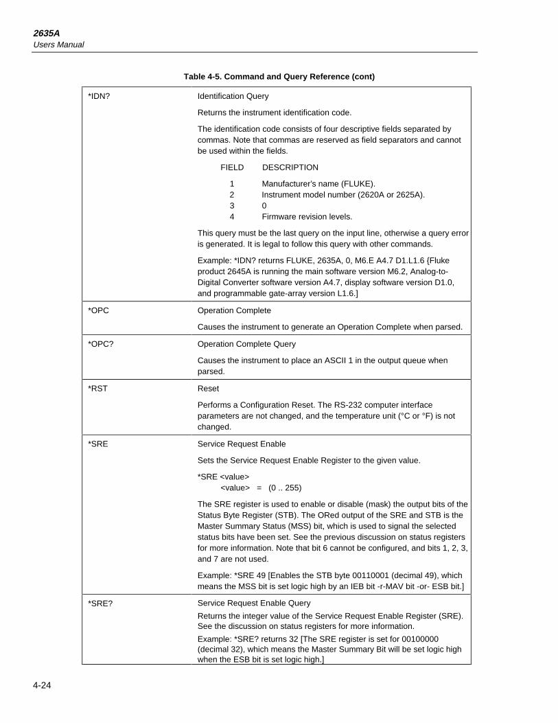
2635AUsers Manual
4-24
Table 4-5. Command and Query Reference (cont)
*IDN? Identification Query
Returns the instrument identification code.
The identification code consists of four descriptive fields separated bycommas. Note that commas are reserved as field separators and cannotbe used within the fields.
FIELD DESCRIPTION
1 Manufacturer’s name (FLUKE). 2 Instrument model number (2620A or 2625A). 3 0 4 Firmware revision levels.
This query must be the last query on the input line, otherwise a query erroris generated. It is legal to follow this query with other commands.
Example: *IDN? returns FLUKE, 2635A, 0, M6.E A4.7 D1.L1.6 Flukeproduct 2645A is running the main software version M6.2, Analog-to-Digital Converter software version A4.7, display software version D1.0,and programmable gate-array version L1.6.]
*OPC Operation Complete
Causes the instrument to generate an Operation Complete when parsed.
*OPC? Operation Complete Query
Causes the instrument to place an ASCII 1 in the output queue whenparsed.
*RST Reset
Performs a Configuration Reset. The RS-232 computer interfaceparameters are not changed, and the temperature unit (°C or °F) is notchanged.
*SRE Service Request Enable
Sets the Service Request Enable Register to the given value.
*SRE <value> <value> = (0 .. 255)
The SRE register is used to enable or disable (mask) the output bits of theStatus Byte Register (STB). The ORed output of the SRE and STB is theMaster Summary Status (MSS) bit, which is used to signal the selectedstatus bits have been set. See the previous discussion on status registersfor more information. Note that bit 6 cannot be configured, and bits 1, 2, 3,and 7 are not used.
Example: *SRE 49 [Enables the STB byte 00110001 (decimal 49), whichmeans the MSS bit is set logic high by an IEB bit -r-MAV bit -or- ESB bit.]
*SRE? Service Request Enable Query
Returns the integer value of the Service Request Enable Register (SRE).See the discussion on status registers for more information.
Example: *SRE? returns 32 [The SRE register is set for 00100000(decimal 32), which means the Master Summary Bit will be set logic highwhen the ESB bit is set logic high.]

Computer OperationsComputer Interface Commands and Operation 4
4-25
Table 4-5. Command and Query Reference (cont)
*STB? Read Status Byte Query
Returns the integer value of the Status Byte, with bit 6 as the mastersummary bit. See the previous discussion on status registers for moreinformation.
Example: *STB returns 97 [The STB register is set for 01100001(decimal 97), which means the Master Summary Bit, Even Status Bit, andinstrument Even Bit are set logic high.]
*TRG Single- Scan Trigger
This command causes the instrument to perform a Single Scan. If a scanis already in progress when this command is parsed, the command isignored.
If logging to memory card is enabled (PRINT_TYPE 3 or 6) and thememory card is missing, full, write-protected, or unformatted, the scan willbe performed but an Execution error will be generated.
*TST? Self Test Query
Causes an internal self test to be run, returning the result as an integer(representing the binary encoded value.) The self test does not require anylocal operator interaction and returns the instrument to the power-up state.The binary coding is:
Bit Binary Value Error
0 1 Boot ROM Checksum Error11 2 Instrument ROM Checksum Error2 4 Internal RAM Test Failed3 8 Display Power-Up Test Failed4 16 Display Bad or Not Installed5 32 Instrument Configuration Corrupted.6 64 Instrument Calibration Data Corrupted7 128 Instrument Not Calibrated8 256 A-to-D Converter Not Responding9 512 A-to-D Converter ROM Test Failed10 1024 A-to-D Converter RAM Test Failed11 2048 A-to-D Converter Self test Failed12 4096 Memory Card Interface Not Installed
Example: *TST? returns 2048 [The A/D self test failed.]
*WAI Wait-to-continue
Prevents the parser from executing any more commands or queries untilthe No-Pending-Operations flag is true. Used in conjunction with *OPCand *OPC?
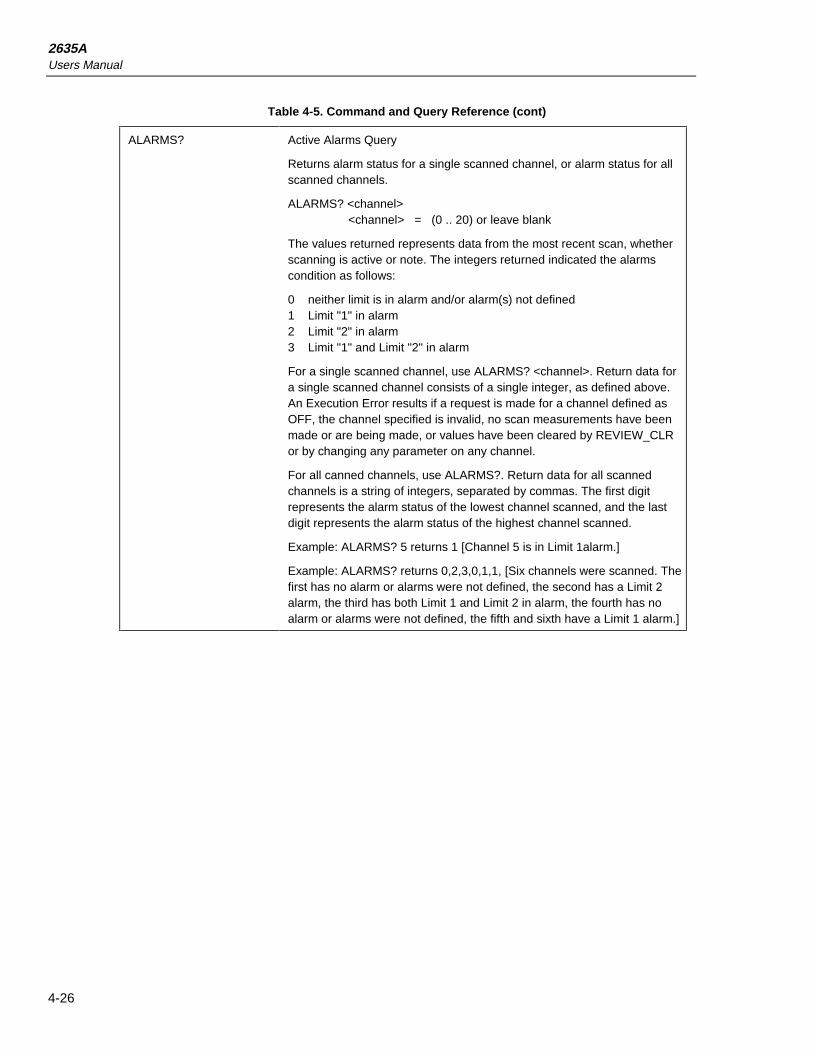
2635AUsers Manual
4-26
Table 4-5. Command and Query Reference (cont)
ALARMS? Active Alarms Query
Returns alarm status for a single scanned channel, or alarm status for allscanned channels.
ALARMS? <channel> <channel> = (0 .. 20) or leave blank
The values returned represents data from the most recent scan, whetherscanning is active or note. The integers returned indicated the alarmscondition as follows:
0 neither limit is in alarm and/or alarm(s) not defined1 Limit "1" in alarm2 Limit "2" in alarm3 Limit "1" and Limit "2" in alarm
For a single scanned channel, use ALARMS? <channel>. Return data fora single scanned channel consists of a single integer, as defined above.An Execution Error results if a request is made for a channel defined asOFF, the channel specified is invalid, no scan measurements have beenmade or are being made, or values have been cleared by REVIEW_CLRor by changing any parameter on any channel.
For all canned channels, use ALARMS?. Return data for all scannedchannels is a string of integers, separated by commas. The first digitrepresents the alarm status of the lowest channel scanned, and the lastdigit represents the alarm status of the highest channel scanned.
Example: ALARMS? 5 returns 1 [Channel 5 is in Limit 1alarm.]
Example: ALARMS? returns 0,2,3,0,1,1, [Six channels were scanned. Thefirst has no alarm or alarms were not defined, the second has a Limit 2alarm, the third has both Limit 1 and Limit 2 in alarm, the fourth has noalarm or alarms were not defined, the fifth and sixth have a Limit 1 alarm.]

Computer OperationsComputer Interface Commands and Operation 4
4-27
Table 4-5. Command and Query Reference (cont)
ALARM_ASSOC Associate Alarm Output
Configures alarm output associations at the rear panel DIGITAL I/Oconnector for channels 4 to 20.
ALARM_ASSOC <channel>,<limit_num>,<DO_line>
<channel> = (4 .. 20)<limit_num> = 1 or 2<DO_line> = (0 .. 7)
This command is used to associate a channel alarm for channels 4 to 20with a rear panel DIGITAL I/O line (I/O 0 to I/O 7). Alarm conditions areasserted with a logical low (nominal =0.7V DC); non-alarm conditions areindicated by a logical high (nominal =5.0V DC). The default setting for 4 to20 are ORed to the I/O lines in groups, as shown below.
I/O 4 I/O 5 I/O 6 I/O 7Chan Chan Chan Chan4 5 6 78 9 10 1112 13 14 1516 17 18 1920
For example, if channel 6 or 10 0r 14 0r 18 goes into alarm (either Limit 1or Limit 2), I/O 6 is asserted. This command changes the default settingsor any other settings, as desired. Any number of channel alarm limits canbe assigned to the same I/O line. For example, all alarms on all channels 4to 20 could assert a single I/O line. Alarm associations can be returned tothe default settings with an *RST configuration reset command. DIGITALI/O lines set logic low remain low unless values have been cleared by anew alarm association, REVIEW_CLR, or by changing any parameter onany channel. If this command is entered during scanning while logging tothe memory card, an Execution Error is generated.
Example: ALARM_ASSOC 10,1,2 [For channel 10, alarm Limit 1, assertDIGITAL I/O line 2].

2635AUsers Manual
4-28
Table 4-5. Command and Query Reference (cont)
ALARM_ASSOC? Alarm Association Query
Returns alarm output associations at the rear panel DIGITAL I/O connectorfor channels 4 to 20.
ALARM_ASSOC?
<channel>,<limit_num><channel> = (4 .. 20)<limit_num> = 1 or 2
This command returns an integer that represents the DIGITAL I/O lineactive at the rear panel DIGITAL I/O connector for the specified channeland alarm limit. If default settings are in effect, returns follow the tablebelow.
I/O 4 I/O 5 I/O 6 I/O 7Chan Chan Chan Chan4 5 6 78 9 10 1112 13 14 1516 17 18 1920
If there is no association between an alarm and DIGITAL I/O line, there isno return and an Execution Error is generated.
Example: ALARM_ASSOC? 10,1 returns 2 [For channel 10, alarm Limit 1,will assert DIGITAL I/O line 2].
ALARM_ASSOC_CLR Clear Alarm Association
Clears an alarm output association at the rear panel DIGITAL I/Oconnector for channels 4 to 20.
ALARM_ASSOC_CLR <channel>,<limit_num><channel> = (4 .. 20)<limit_num> = 1 2
This command removes all association between a DIGITAL I/O line at therear panel DIGITAL I/O connector for the specified channels 4 to 20 andalarm limit. After application of this command, the previously associatedDIGITAL I/O line is set high and new alarm conditions on this channel’salarm limit will not assert the DIGITAL I/O line. If this command is enteredduring scanning while logging to the memory card, and Execution Error isgenerated.
Example: ALARM_ASSOC>CLR 10,1 [Channel 10, alarm Limit 1, removeall association with a DIGITAL I/O line.]
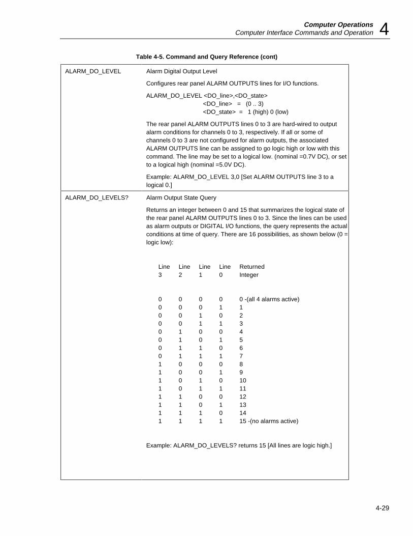
Computer OperationsComputer Interface Commands and Operation 4
4-29
Table 4-5. Command and Query Reference (cont)
ALARM_DO_LEVEL Alarm Digital Output Level
Configures rear panel ALARM OUTPUTS lines for I/O functions.
ALARM_DO_LEVEL <DO_line>,<DO_state><DO_line> = (0 .. 3)<DO_state> = 1 (high) 0 (low)
The rear panel ALARM OUTPUTS lines 0 to 3 are hard-wired to outputalarm conditions for channels 0 to 3, respectively. If all or some ofchannels 0 to 3 are not configured for alarm outputs, the associatedALARM OUTPUTS line can be assigned to go logic high or low with thiscommand. The line may be set to a logical low. (nominal =0.7V DC), or setto a logical high (nominal =5.0V DC).
Example: ALARM_DO_LEVEL 3,0 [Set ALARM OUTPUTS line 3 to alogical 0.]
ALARM_DO_LEVELS? Alarm Output State Query
Returns an integer between 0 and 15 that summarizes the logical state ofthe rear panel ALARM OUTPUTS lines 0 to 3. Since the lines can be usedas alarm outputs or DIGITAL I/O functions, the query represents the actualconditions at time of query. There are 16 possibilities, as shown below (0 =logic low):
Line Line Line Line Returned3 2 1 0 Integer
0 0 0 0 0 -(all 4 alarms active)0 0 0 1 10 0 1 0 20 0 1 1 30 1 0 0 40 1 0 1 50 1 1 0 60 1 1 1 71 0 0 0 81 0 0 1 91 0 1 0 101 0 1 1 111 1 0 0 121 1 0 1 131 1 1 0 141 1 1 1 15 -(no alarms active)
Example: ALARM_DO_LEVELS? returns 15 [All lines are logic high.]
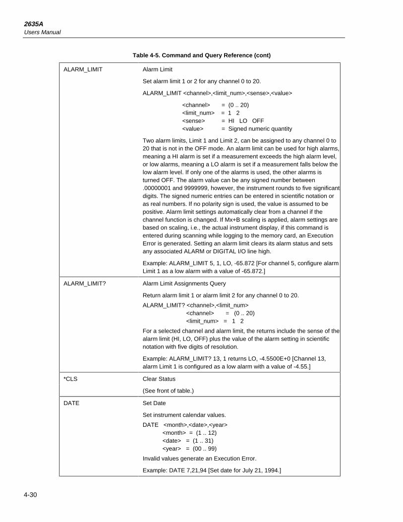
2635AUsers Manual
4-30
Table 4-5. Command and Query Reference (cont)
ALARM_LIMIT Alarm Limit
Set alarm limit 1 or 2 for any channel 0 to 20.
ALARM_LIMIT <channel>,<limit_num>,<sense>,<value>
<channel> = (0 .. 20)<limit_num> = 1 2<sense> = HI LO OFF<value> = Signed numeric quantity
Two alarm limits, Limit 1 and Limit 2, can be assigned to any channel 0 to20 that is not in the OFF mode. An alarm limit can be used for high alarms,meaning a HI alarm is set if a measurement exceeds the high alarm level,or low alarms, meaning a LO alarm is set if a measurement falls below thelow alarm level. If only one of the alarms is used, the other alarms isturned OFF. The alarm value can be any signed number between.00000001 and 9999999, however, the instrument rounds to five significantdigits. The signed numeric entries can be entered in scientific notation oras real numbers. If no polarity sign is used, the value is assumed to bepositive. Alarm limit settings automatically clear from a channel if thechannel function is changed. If Mx+B scaling is applied, alarm settings arebased on scaling, i.e., the actual instrument display, if this command isentered during scanning while logging to the memory card, an ExecutionError is generated. Setting an alarm limit clears its alarm status and setsany associated ALARM or DIGITAL I/O line high.
Example: ALARM_LIMIT 5, 1, LO, -65.872 [For channel 5, configure alarmLimit 1 as a low alarm with a value of -65.872.]
ALARM_LIMIT? Alarm Limit Assignments Query
Return alarm limit 1 or alarm limit 2 for any channel 0 to 20.
ALARM_LIMIT? <channel>,<limit_num><channel> = (0 .. 20)<limit_num> = 1 2
For a selected channel and alarm limit, the returns include the sense of thealarm limit (HI, LO, OFF) plus the value of the alarm setting in scientificnotation with five digits of resolution.
Example: ALARM_LIMIT? 13, 1 returns LO, -4.5500E+0 [Channel 13,alarm Limit 1 is configured as a low alarm with a value of -4.55.]
*CLS Clear Status
(See front of table.)
DATE Set Date
Set instrument calendar values.
DATE <month>,<date>,<year><month> = (1 .. 12)<date> = (1 .. 31)<year> = (00 .. 99)
Invalid values generate an Execution Error.
Example: DATE 7,21,94 [Set date for July 21, 1994.]

Computer OperationsComputer Interface Commands and Operation 4
4-31
Table 4-5. Command and Query Reference (cont)
DIO_LEVELS? Digital I/O State Query
Returns an integer between 0 and 255 that summarizes the logical state of the rearpanel DIGITAL I/O lines 0 to 7. A logical 0 (low) means the line is asserted. Since thelines can be used as alarm outputs of digital inputs or outputs, the return represents theactual conditions at time of query. There are 256 possibilities, as shown in Appendix E.
Example: DIO_LEVELS? returns 145 [DIGITAL I/O lines 1, 2, 3, 5 and 6 are asserted(logic low).]
DIR Memory Card Files Directory
Print a formatted listing of files on the memory card. This includes number of files, bytesused, and bytes free. While the directory is printing, all other operations in theinstrument are suspended. If hardware or software flow control stall this output, theinstrument waits for the output to be unstalled.
Example; DIR returns:
DAT00.HYD 826 07-21-1994 16:20
DAT01.HYD 1082 07-21-1994 16:50
SET00.HYD 730 07-21-1994 17:10
SET01 HYD 730 07-21-1994 18:30
4 FILE (S) 3368 BYTES
1030656 BYTES FREE
DO_LEVEL Set Digital Output Level
Configures the eight rear panel DIGITAL I/O connector lines, I/O connector lines, I/O 0to I/O 7.
DO_LEVEL <DO_line>,<DO_state><DO_line> = (0 .. 7)<DO_state> = 1 0
The rear panel DIGITAL I/O connector has eight lines, 0 to 7. Each line can be assignedto an I/O function. With this command, the line may be set to a logical low (nominal+0.7V DC), or set to a logical high (nominal +5.0V DC). DIGITAL I/O lines are assertedwhile scanning. When scanning stops, the I/O lines set logic low remain low unlessvalues have been cleared by a new DO_LEVEL command, REVIEW_CLR, or bychanging any parameter on any channel. Since I/O lines are shared with the alarmoutputs of channels 4 to 20, verify DO_LEVEL commands will not cause ambiguities.(See the ALARM_ASSOC_CLR command to disassociate an alarm with an I/o line.) Ifthis command is entered during scanning while logging to the memory card, anExecution Error is generated.
Example: DO_LEVEL 4, 0 [Set I/o line 4 to a logical 0 (low).]

2635AUsers Manual
4-32
Table 4-5. Command and Query Reference (cont)
ECHO Enable/Disable RS-232 Echo Mode
ECHO <1 0>
1 = Turn RS-232 echoing on.0 = Turn RS-232 echoing off.
The echo on mode allows character strings sent from the host to theinstrument, to return (echo) back to the host. When operating theinstrument from a terminal (or computer in the terminal emulation mode),ECHO 1 is usually selected. If this command is entered during scanningwhile logging to the memory card, an Execution Error is generated.
*ESE Event Status Enable
(See front of table.)
*ESE? Event Status Enable Query
(See front of table.)
*ESR? Event Status Enable Query
(See front of table.)
FILE_ERROR? File Error Query
Returns an integer number representing the last memory card error thatwas encountered. Once set, this value is only cleared (set to zero) byperforming this query.
The possible card error codes are:
0 No error since last queried or power up.
Card error. No card, invalid file system on card, no file system on card,format operation failed, file could not be removed, and all other I/Oerrors.
Bad file name, or out of file names (all 100 file names of the type beingoperated on are in used).
Card error during scanning, but no data has been lost. Usually occurswhen card fills during scanning.
Card error during scanning, and data is being lost. The oldest scan data inqueue is being lost as each new scan completes.
FILE_LOAD Configuration File LoadLoads the instrument configuration from a memory card configuration ordata file.FILE_LOAD <file>
<file> = SET00.HYD, SET01.HYD, ... SET99.HYD-or- <file> = DAT00.HYD, DAT01.HYD, ... DAT99.HYDExecution error if the file does not exist, if the file is not an instrumentconfiguration or data file, if the file name is not valid, the card is notinstalled, or the card is not formatted. An execution error is also generatedif either scanning or monitor is active. The file name convention is notchecked (a data file may be loaded to recover a configuration).Example: FILE_LOAD SET68.HYD [Loads configuration file SET68.HYDas the new instrument configuration.]

Computer OperationsComputer Interface Commands and Operation 4
4-33
Table 4-5. Command and Query Reference (cont)
FILE_OPEN Data File Open
Opens a data file for measurement logging.
FILE_OPEN <file>
<file> = DAT00.HYD, DAT01.HYD, DAT99.HYD
All scans are appended to this file until a file close is performed. Thespecial name ’*’ opens the next available file in sequence. If no highernumbered file can be found, the algorithm "wraps" to zero and keepssearching. If no more file names are available, an Execution Error isgenerated. If the given file already exists, the file name does not match theconvention, or scanning is already active, an Execution Error is generated.Logging is turned on and the card destination activated if this command issuccessfully executed.
Example: FILE_OPEN DAT31.HYD [Open data file DAT31.HYD for datalogging.]
FILE_OPEN? Data File Open Query.
Returns the name of the data file to be used for logging, or an ExecutionError if no file is open.
Example: FILE_OPEN? returns DAT05.HYD [The file DAT05.HYDis open for data logging.]
FILE_REMOVE File Remove
Remove the given file from the memory card.
FILE_REMOVE
<file>
<file> = DAT00.HYD, DAT01.HYD, ... DAT99.HYD
or-
<file> = SET00.HYD, SET01.HYD, ... SET99.HYD
Removing the currently open data file will cause any scan data stored ininternal memory waiting to be written to the file to be lost.
An Execution Error is generated if the file does not exist, the card is write-protected, the file name is invalid, card is not installed or the card is notformatted. The file name convention is not checked.
Example: FILE_REMOVE DAT00.HYD [Remove the DAT00.HYD file.]

2635AUsers Manual
4-34
Table 4-5. Command and Query Reference (cont)
FILE_RX File Receive
The normal serial protocol is suspended and a binary transfer (XMODEM)is started between the instrument memory card and the host computer.Received data is typically an instrument configuration file transmitted fromthe host computer and uses the naming convention, SETxx.HYD. If the filealready exists it is overwritten.
FILE_RX
<file><file> = SET00.HYD, SET01.HYD, ... SET99.HYD
An Execution Error is generated under any of the following conditions: thecard is not installed; the card is not formatted; the file cannot be created;scan or monitor is active; the instrument is configured for even or oddparity (parity must be "none"); or the instrument is configured for Echo On(Echo must be "Off"). See the FILE_TX command for transmitting datafiles. The file name convention is not checked, so any file may betransferred to the memory card.
FILE_SPACE? File Space
Returns the number of kilobytes available for files on the memory card.
Example: FILE_SPACE? returns 1003 [There are 1003 kilobytes free onthe memory card.]
FILE_STORE Configuration File Store
Saves present instrument configuration in the given file.
FILE_STORE
<file>
<file> = SET00.HYD, SET01.HYD, ... SET99.HYD
Configuration file names must match the naming convention ’SETxx.HYD’where xx is a two-digit integer number. If the given file already exists, it isoverwritten. If there is not enough room to store a new configuration file, ifthe card is write-protected, card is not installed, or card is not formatted,an Execution Error is generated.
Example: FILE_STORE SET21.HYD [Save the present instrumentconfiguration in the file SET21.HYD.]

Computer OperationsComputer Interface Commands and Operation 4
4-35
Table 4-5. Command and Query Reference (cont)
FILE_TAG? Configuration File Tag
Return the tag from the given configuration or data file (<file> specified), orthe present configuration tag (no <file> specified).
FILE_TAG? <file>
<file>= DAT00.HYD, DAT01.HYD, ... DAT99.HYD
-or-
<file> = SET00.HYD, SET01.HYD, ... SET99.HYD
-or- leave blank
Instrument-created configurations use the configuration file nameSETxx.HYD for this tag. If no tag has ever been used since the last fullreset, or the specified file does not exist, an Execution Error is generated.
Example: FILE_TAG? SET17.HYD returns TESTFILE [Presentconfiguration tag in SET17.HYD is the string TESTFILE (set by the user).]
FILE_TX File Transmit
The normal serial protocol is suspended and a binary transfer (XMODEM)is started between the instrument memory card and the host computer.The instrument will transmit a DATxx.HYD file or SETxx.HYD file to thehost computer.
FILE_TX <file><file> = DAT00.HYD, DAT01.HYD, ... DAT99.HYD
-or-
<file> = SET00.HYD, SET01.HYD, ... SET99.HYD
An Execution Error is generated under any of the following conditions: thecard is not installed; the card is not formatted; the file does not exist; scanor monitor is active; the instrument is configured for even or odd parity(parity must be "none"); or the instrument is configured for Echo On (Echomust be "Off"). See the FILE_RX command for receiving instrumentconfiguration files. The file name convention is not checked, so any filemay be transferred to the memory card.

2635AUsers Manual
4-36
Table 4-5. Command and Query Reference (cont)
FORMAT Response Format
Set the output format type to include or exclude measurement units.
FORMAT 1 Measurements returned without units.
FORMAT 2 Measurements returned with units.
Commands that return measurement data (like LAST?, NEXT?, MIN?,MAX?) can be expressed as a number only (FORMAT 1) or as a numberwith a measurement unit (FORMAT 2). If this command is entered duringscanning while logging to the memory card, an Execution Error isgenerated. The measurement units are:
MEASUREMENT UNITS STRINGScaled MX+B”Volts DC “VDC”Volts AC “VAC”Resistance “OHMS”Frequency “Hz”Temperature °C “C”Temperature °F “F”
With FORMAT 1 asserted, typical returns would be +890.22E+0,+230.96E-3, 072.4E+0, +003.2E; with FORMAT 2 asserted, the returnswould be +890.22E+0 HZ,+230.96E-3 VAC, 072.4E+0 F, +003.2E+0Mx+B.
FORMAT? Query Response Format
Returns the output format type.
1 Measurements returned without units.
2 Measurements returned with units.
Commands that return measurement data (like LAST?, NEXT?, MIN?,MAX?) can be expressed as a number only (FORMAT 1) or as a numberwith a measurement unit (FORMAT 2). The measurement units are:
MEASUREMENT UNITS STRINGScaled MX+B”Volts DC “VDC”Volts AC “VAC”Resistance “OHMS”Frequency “Hz”Temperature °C “C”Temperature °F “F”
Example: FORMAT? returns 2 [Measurement data will be returned with aunits indicator, e.g., +230.96E-3 VAC.]
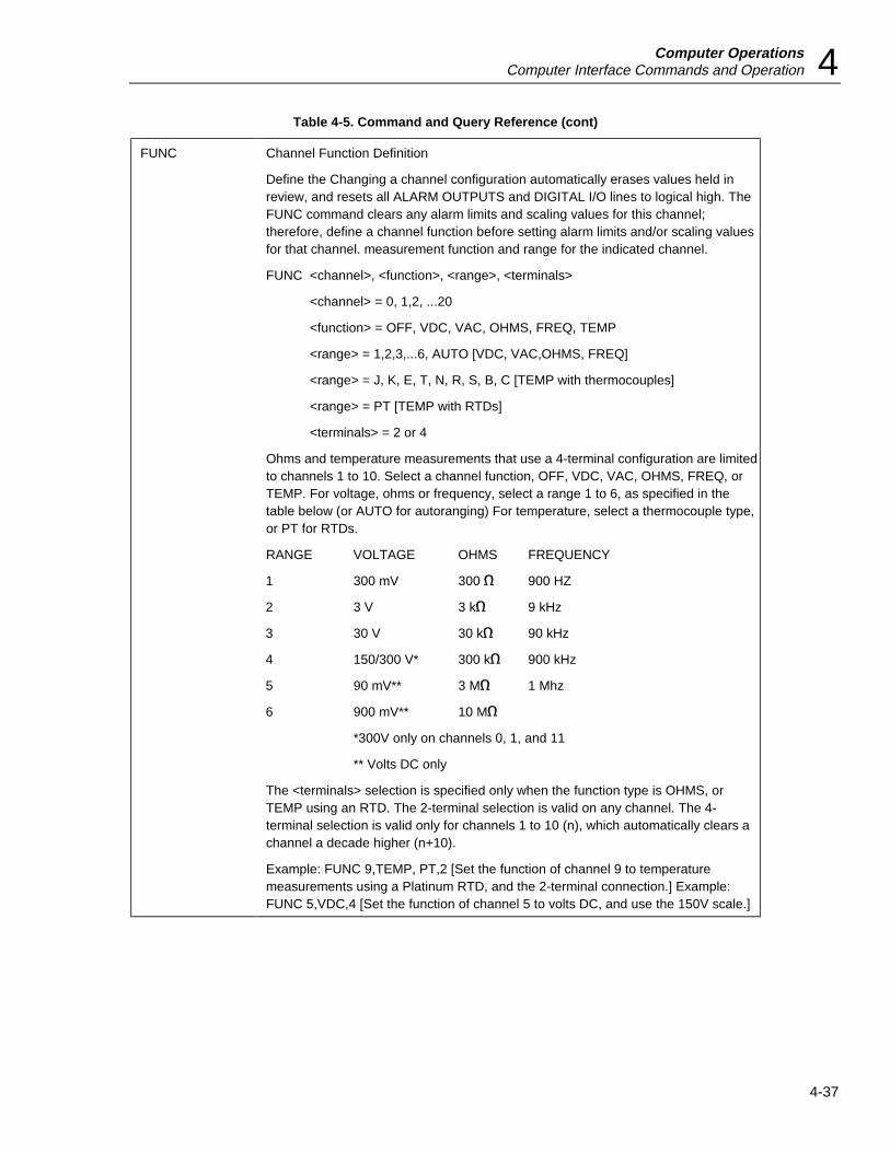
Computer OperationsComputer Interface Commands and Operation 4
4-37
Table 4-5. Command and Query Reference (cont)
FUNC Channel Function Definition
Define the Changing a channel configuration automatically erases values held inreview, and resets all ALARM OUTPUTS and DIGITAL I/O lines to logical high. TheFUNC command clears any alarm limits and scaling values for this channel;therefore, define a channel function before setting alarm limits and/or scaling valuesfor that channel. measurement function and range for the indicated channel.
FUNC <channel>, <function>, <range>, <terminals>
<channel> = 0, 1,2, ...20
<function> = OFF, VDC, VAC, OHMS, FREQ, TEMP
<range> = 1,2,3,...6, AUTO [VDC, VAC,OHMS, FREQ]
<range> = J, K, E, T, N, R, S, B, C [TEMP with thermocouples]
<range> = PT [TEMP with RTDs]
<terminals> = 2 or 4
Ohms and temperature measurements that use a 4-terminal configuration are limitedto channels 1 to 10. Select a channel function, OFF, VDC, VAC, OHMS, FREQ, orTEMP. For voltage, ohms or frequency, select a range 1 to 6, as specified in thetable below (or AUTO for autoranging) For temperature, select a thermocouple type,or PT for RTDs.
RANGE VOLTAGE OHMS FREQUENCY
1 300 mV 300 e 900 HZ
2 3 V 3 ke 9 kHz
3 30 V 30 ke 90 kHz
4 150/300 V* 300 ke 900 kHz
5 90 mV** 3 Me 1 Mhz
6 900 mV** 10 Me
*300V only on channels 0, 1, and 11
** Volts DC only
The <terminals> selection is specified only when the function type is OHMS, orTEMP using an RTD. The 2-terminal selection is valid on any channel. The 4-terminal selection is valid only for channels 1 to 10 (n), which automatically clears achannel a decade higher (n+10).
Example: FUNC 9,TEMP, PT,2 [Set the function of channel 9 to temperaturemeasurements using a Platinum RTD, and the 2-terminal connection.] Example:FUNC 5,VDC,4 [Set the function of channel 5 to volts DC, and use the 150V scale.]

2635AUsers Manual
4-38
Table 4-5. Command and Query Reference (cont)
FUNC? Channel Function Query
Return the complete function for the indicated channel.
FUNC? <channel><channel> = (0 .. 20)
The returns are in comma-separated data fields using the following format:
<function>,<range>,<terminals>
The <function> return is OFF, VDC, VAC, OHMS, FREQ, or TEMP. For voltage,ohms, or frequency the <range> return is a number 1 through 6 (see below) orAUTO for autoranging. The <range> return for temperature is a thermocouple type[J, K, E, T, N, R, S, B, C] or PT for RTD measurements. The <terminals> return is forOHMS and TEMP functions only and is either 2 for 2-terminal measurements or 4 for4-terminal measurements.
Example: FUNC? 8 returns TEMP, PT,4 [The function of channel 8 is temperature,using a Platinum resistance-temperature-detector (RTD), and a 4-terminalmeasurement configuration
*IDN? Identification Query
(See front of table.)
IEE Instrument Event Enable
Sets the Instrument Event Enable Register to the given value.
IEE <value><value> = (0 .. 255)
The IEE register is used to enable or disable (mask) the output bits of the InstrumentEvent Register (IER). The combined output of the IEE and IER is the InstrumentEvent Bit (IEB), which is used as an input for the Status Byte Register. See thediscussion on status registers for more
information.
Example: IEE 5 [Enables the IER output byte 00000101 (decimal 5), which meansan Open Thermocouple -or- Alarm Limit Transition will set IEB logic high.]
IEE? Instrument Event Enable Query
Returns the present value of the Instrument Event Enable Register as an integer.
IEE? Instrument Event Register Query
Returns the present value of the Instrument Event Enable Register (IEE) as aninteger, as selected with the IEE command. See the discussion on status registersfor more information.
Example: IEE? returns 128 [The IEE register is set for 10000000 (decimal 128),which means a Scan Complete will set IEB logic high.]
IER? Instrument Event Register Query
Returns the value of the Instrument Event Register (IER) as an integer, then clearsthe register to 0. See the discussion on status registers for more information.
Example: IER? returns 133 [The IER register is set for 10000101 (decimal 133),which means a Scan Complete, Open Thermocouple, and Alarm Limit Transitionwere detected.]
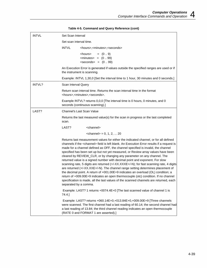
Computer OperationsComputer Interface Commands and Operation 4
4-39
Table 4-5. Command and Query Reference (cont)
INTVL Set Scan Interval
Set scan interval time.
INTVL <hours>,<minutes>,<seconds>
<hours> = (0 .. 9)<minutes> = (0 .. 99)<seconds> = (0 .. 99)
An Execution Error is generated if values outside the specified ranges are used or ifthe instrument is scanning.
Example: INTVL 1,30,0 [Set the interval time to 1 hour, 30 minutes and 0 seconds.]
INTVL? Scan Interval Query
Return scan interval time. Returns the scan interval time in the format<hours>,<minutes>,<seconds>.
Example INTVL? returns 0,0,0 [The interval time is 0 hours, 0 minutes, and 0seconds (continuous scanning).]
LAST? Channel’s Last Scan Value
Returns the last measured value(s) for the scan in progress or the last completedscan.
LAST? <channel>
<channel> = 0, 1, 2, ... 20
Returns last measurement values for either the indicated channel, or for all definedchannels if the <channel> field is left blank. An Execution Error results if a request ismade for a channel defined as OFF, the channel specified is invalid, the channelspecified has been set up but not yet measured, or Review array values have beencleared by REVIEW_CLR, or by changing any parameter on any channel. Thereturned value is a signed number with decimal point and exponent. For slowscanning rate, 5 digits are returned (+/-XX.XXXE+/-N); for fast scanning rate, 4 digitsare returned (+/-XX.XXE+/-N). The channel range setting determines placement ofthe decimal point. A return of +001.00E+9 indicates an overload (OL) condition; areturn of +009.00E+9 indicates an open thermocouple (otc) condition. If no channelspecification is made, all the last values of the scanned channels are returned, eachseparated by a comma.
Example: LAST? 1 returns +0074.4E+0 [The last scanned value of channel 1 is74.4.]
Example: LAST? returns +060.14E+0,+013.84E+0,+009.00E+9 [Three channelswere scanned. The first channel had a last reading of 60.14; the second channel hada last reading of 13.84; the third channel reading indicates an open thermocouple(RATE 0 and FORMAT 1 are asserted).]
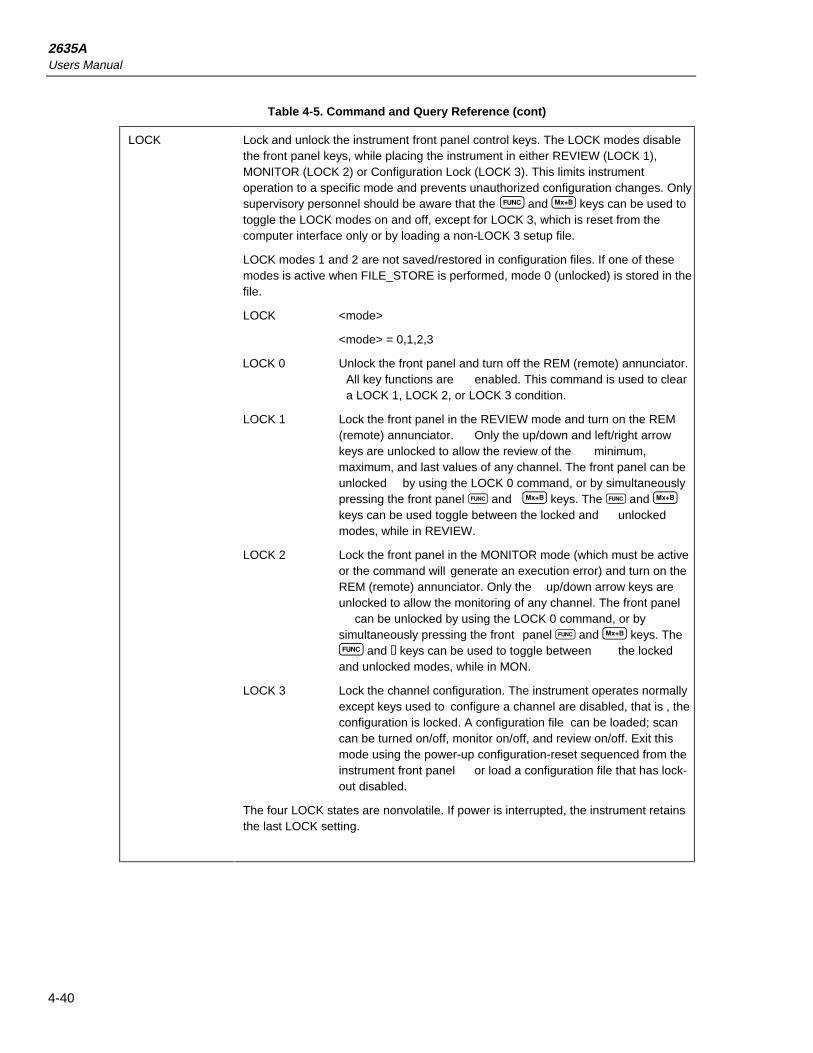
2635AUsers Manual
4-40
Table 4-5. Command and Query Reference (cont)
LOCK Lock and unlock the instrument front panel control keys. The LOCK modes disablethe front panel keys, while placing the instrument in either REVIEW (LOCK 1),MONITOR (LOCK 2) or Configuration Lock (LOCK 3). This limits instrumentoperation to a specific mode and prevents unauthorized configuration changes. Onlysupervisory personnel should be aware that the F and B keys can be used totoggle the LOCK modes on and off, except for LOCK 3, which is reset from thecomputer interface only or by loading a non-LOCK 3 setup file.
LOCK modes 1 and 2 are not saved/restored in configuration files. If one of thesemodes is active when FILE_STORE is performed, mode 0 (unlocked) is stored in thefile.
LOCK <mode>
<mode> = 0,1,2,3
LOCK 0 Unlock the front panel and turn off the REM (remote) annunciator.All key functions are enabled. This command is used to cleara LOCK 1, LOCK 2, or LOCK 3 condition.
LOCK 1 Lock the front panel in the REVIEW mode and turn on the REM(remote) annunciator. Only the up/down and left/right arrowkeys are unlocked to allow the review of the minimum,maximum, and last values of any channel. The front panel can beunlocked by using the LOCK 0 command, or by simultaneouslypressing the front panel F and B keys. The F and Bkeys can be used toggle between the locked and unlockedmodes, while in REVIEW.
LOCK 2 Lock the front panel in the MONITOR mode (which must be activeor the command will generate an execution error) and turn on theREM (remote) annunciator. Only the up/down arrow keys areunlocked to allow the monitoring of any channel. The front panel
can be unlocked by using the LOCK 0 command, or bysimultaneously pressing the front panel F and B keys. TheF and b keys can be used to toggle between the lockedand unlocked modes, while in MON.
LOCK 3 Lock the channel configuration. The instrument operates normallyexcept keys used to configure a channel are disabled, that is , theconfiguration is locked. A configuration file can be loaded; scancan be turned on/off, monitor on/off, and review on/off. Exit thismode using the power-up configuration-reset sequenced from theinstrument front panel or load a configuration file that has lock-out disabled.
The four LOCK states are nonvolatile. If power is interrupted, the instrument retainsthe last LOCK setting.

Computer OperationsComputer Interface Commands and Operation 4
4-41
Table 4-5. Command and Query Reference (cont)
LOCK? Returns the instrument front panel lock status, as selected with the LOCK command.
0 Front panel keys are unlocked. All key functions are enabled.
1 Front panel keys are locked, except for up/down and left/right arrowkeys, which are used to review the minimum, maximum and lastvalues of any channel
2 Front panel keys are unlocked, except for the up/down arrow keys,which are used to monitor any channel.
3 Front panel keys can be used, except those used to configure achannel.
LOCS Local without Lockout
All front panel keys are enabled, and the REM annunciator is not lit. This is the stateassumed by the instrument at power-up reset. To disable all the front panel keys,use the LWLS command.
LOG? Retrieve Logged Data Query
Return the oldest logged scan values for all configured channels and remove themfrom internal memory (maximum 100 scans). This query is valid during scanning.The remaining count of stored scans (LOG_COUNT? command) is decremented by1. Channels defined as OFF are not included. If there are no logged scans toremove, an
Execution Error is generated.
The returns includes the following information:
• Date and time at the start of the logged scan.
• Values for the channels measured.
• Status of ALARM OUTPUTS, DIGITAL I/O, and totalize count.
Logging scans in internal memory is enabled by the PRINT and PRINT_TYPEcommands.
Example: LOG? returns 16,15,30,7,21,94,+034.53E-3 VAC,+09.433E+0VDC,+1.2043E+6 OHMS,15,255,+00.000E+3 [The oldest recorded scan, thatstarted at 1600 hours, 15 minutes, 30 seconds, on July 21, 1994, measured threechannels with readings 34.53mVAC, 9.433 VDC, 1.2043 M OHMS, with ALARMOUTPUTS status 15, DIGITAL I/O status 255, and totalize count of 0 (RATE 0 andFORMAT 2 are asserted).]
LOGGED? Retrieve specified scan data from internal memory.
LOGGED? <index> <index> = (1,2, 3, .. , 100)
A maximum of 100 scans can be recorded in the internal memory. This command isused to retrieve a particular scan. If the <<index>> number has no associated scan,an Execution Error is returned. Logging scans in internal memory is enabled by thePRINT and PRINT_TYPE commands.
Scan data is returned in the same format as for the LOG? query.

2635AUsers Manual
4-42
Table 4-5. Command and Query Reference (cont)
LOG_BIN? Binary Upload of Logged Data
Returns a single ASCII string, which encodes the raw binary data stored at thespecified <index> position.
LOG_BIN? <index>
<index> = 1, 2, 3, ... 100
See Appendix C for a discussion of the LOG_BIN? command.
LOG_CLR Clear Logged Scans
Clear all stored scan data from internal memory (maximum 100 scans).
LOG_CLR_1 Clear Oldest Logged Scan
Clears the oldest (first) scan in the internal memory. If there are no scans in internalmemory, an Execution Error is generated. A total of 100 scans can be saved in thelog queue.
LOG_COUNT? Logged Scan Count Query
Return the number of stored scans. Returns an integer value representing thenumber of scans presently stored in memory. (maximum 100) 0 indicates that thereare no stored scans.
Logging scans in internal memory is enabled by the PRINT and PRINT_TYPEcommands.
Example: LOG_COUNT? returns 33 [The internal memory holds data from the last33 scans.]
LOG_MODE Action when Internal Memory is Full.
Determines what action is taken when 100 scans have been recorded
LOG_MODE 0 the oldest scans and record new scans.
LOG_MODE 1 Maintain the oldest scans and discard new
The LOG_MODE setting is nonvolatile and cannot be changed from the instrumentfront panel. The default is LOG_MODE 0.
LOG_MODE? Action when Internal Memory is Full Query
Returns 0 or 1 to indicate what action will be taken when 100 scans have beenrecorded
0 Discarding the oldest scans to record new scans.
1 Maintaining the oldest scans and discarding new scans
LWLS Local with Lockout
All front panel keys are disabled. The REM annunciator is not lit. This command canbe used when the instrument is scanning or monitoring. To clear, use the LOCScommand.

Computer OperationsComputer Interface Commands and Operation 4
4-43
Table 4-5. Command and Query Reference (cont)
MAX? Channel’s Maximum Value
Returns the maximum value(s) measured since the review array was last cleared.Channel’s Maximum Value
MAX? <channel><channel> = 0, 1, 2, ...20, or leave blank
Returns maximum measurement values for either the indicated channel, or for alldefined channels if the <channel> field is left blank. An Execution Error results if arequest is made for a channel defined as OFF, the channel specified is invalid, thechannel specified has been set up but not yet measured, or Review array valueshave been cleared by REVIEW_CLR, or by changing any parameter on any channel.The return is a signed number with decimal point and exponent. For slow scanningrate, 5 digits are returned (+/-XX.XXXE+/-N); for fast scanning rate, 4 digits arereturned (+/-XX.XXE+/-N). The channel range setting determines placement of thedecimal point. A return of +001.00E+9 indicates an overload (OL) condition; a returnof +009.00E+9 indicates an open thermocouple (otc) condition. If no channelspecification is made, all the maximum values of the scanned channels are returned,each separated by a comma.
Example: MAX? 1 returns +022.34E+0 [The maximum scanned value of channel 1 is22.34.]
Example: MAX? returns +009.00E+9,+890.22E+0,+230.96E-3 [Three channels werescanned. The first channel shows an open thermocouple; the second channel had amaximum reading of 890.22; the third channel had a maximum reading of 0.230(RATE 0 and FORMAT 1 are asserted).]
MCARD? Memory Card StatusReturns the memory card status as an encoded integer number from a binarynumber using bits 0 to 4.
Bit 0 - Card changed; remaining bits differ from the last queryBit 1 - A card is present in the unitBit 2 - Card is write protectedBit 3, 4 - Battery status of last inserted card, as below:
BIT 4 BIT 3 MEMORY CARD BATTERY STATUS0 0 Battery operational0 1 Battery should be replaced; data is OK1 0 Battery and data integrity not guaranteed1 1 Battery and data integrity not guaranteed
Example: MCARD? returns 7 [The memory card status is 00111 (decimal 7),meaning the card changed since the last query, a card is in the unit, the card is writeprotected, and battery is operational.]

2635AUsers Manual
4-44
Table 4-5. Command and Query Reference (cont)
MCARD_DIR? Memory Card Directory
Returns a terminated string for each file in the root directory of the memory card. Thestring is a comma-separated list of the file’s name, size, modification date (day,month, year) and time (hours, minutes, seconds).
Example: MCARD_DIR? returns:
DAT00.HYD,826,7,21,1994,16,20,44
DAT01.HYD,810,7,21,1994,16,50,10
SET00.HYD,730,7,21,1994,17,10,32
SET01.HYD,730,7,21,1994,18,30,03
MCARD_FORMAT Format Memory Card
Memory card inserted in the Data Bucket will be formatted. The card must be thestatic RAM (SRAM) type, meeting PCMCIA standards. An Execution Error isgenerated and the card not formatted if scanning is in progress, the card is ofunknown size, or card is write-protected. If the memory card contains a PCMCIAcard information structure (CIS), the card size is determined from the CIS.Otherwise, the size is algorithmically determined by writing to the memory card. ACIS is never written to the card.
When formatting a memory card, any scan data that has been stored in internalmemory waiting to be written to a valid memory card will be lost.
MCARD_SIZE? Memory Card Size
Returns the memory card size as an integer number of kilobytes.
Example: MCARD_SIZE? returns 1024 [Memory card size is 1024 kilobytes (1megabyte).]
MIN? Channel’s Minimum Value
Returns the minimum value(s) measured since the review array was last cleared.
MIN? <channel>>
<channel> = 0, 1, 2, ... 20, or leave blank
Returns minimum measurement values for either the indicated channel, or for alldefined channels if the <channel>field is left blank. An Execution Error results if arequest is made for a channel defined as OFF, the channel specified is invalid, thechannel specified has been set up but not yet measured, or Review array valueshave been cleared by REVIEW_CLR, or by changing any parameter on any channel.
The return is a signed number with decimal point and exponent. For slow scanningrate, 5 digits are returned (+/-XX.XXXE+/-N); for fast scanning rate, 4 digits arereturned (+/-XX.XXE+/-N). The channel range setting determines placement of thedecimal point. A return of +001.00E+9 indicates an overload (OL) condition; a returnof +009.00E+9 indicates an open thermocouple (otc) condition. If no channelspecification is made, all the minimum values of the scanned channels are returned,each separated by a comma.
Example: MIN? 16 returns +167.85E+3 [The minimum scanned value of channel 16is 167,850 (RATE 0 and FORMAT 1 are asserted).]
Example: MIN? returns +091.67E+0,+001.00E+9,+115.21E-3 [Three channels werescanned. The first channel had a minimum reading of 91.67; the second channel isin overload (OL); the third channel had a minimum reading of 0.11521 (RATE 0 andFORMAT 1 are asserted).]
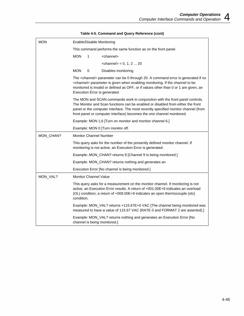
Computer OperationsComputer Interface Commands and Operation 4
4-45
Table 4-5. Command and Query Reference (cont)
MON Enable/Disable Monitoring
This command performs the same function as on the front panel.
MON 1 <channel>
<channel> = 0, 1, 2 ... 20
MON 0 Disables monitoring
The <channel> parameter can be 0 through 20. A command error is generated if no<channel> parameter is given when enabling monitoring. If the channel to bemonitored is invalid or defined as OFF, or if values other than 0 or 1 are given, anExecution Error is generated.
The MON and SCAN commands work in conjunction with the front panel controls.The Monitor and Scan functions can be enabled or disabled from either the frontpanel or the computer interface. The most recently specified monitor channel (fromfront panel or computer interface) becomes the one channel monitored.
Example: MON 1,6 [Turn on monitor and monitor channel 6.]
Example: MON 0 [Turn monitor off.
MON_CHAN? Monitor Channel Number
This query asks for the number of the presently defined monitor channel. Ifmonitoring is not active, an Execution Error is generated.
Example: MON_CHAN? returns 9 [Channel 9 is being monitored.]
Example: MON_CHAN? returns nothing and generates an
Execution Error [No channel is being monitored.]
MON_VAL? Monitor Channel Value
This query asks for a measurement on the monitor channel. If monitoring is notactive, an Execution Error results. A return of +001.00E+9 indicates an overload(OL) condition; a return of +009.00E+9 indicates an open thermocouple (otc)condition.
Example: MON_VAL? returns +115.67E+0 VAC [The channel being monitored wasmeasured to have a value of 115.67 VAC (RATE 0 and FORMAT 2 are asserted).]
Example: MON_VAL? returns nothing and generates an Execution Error [Nochannel is being monitored.]
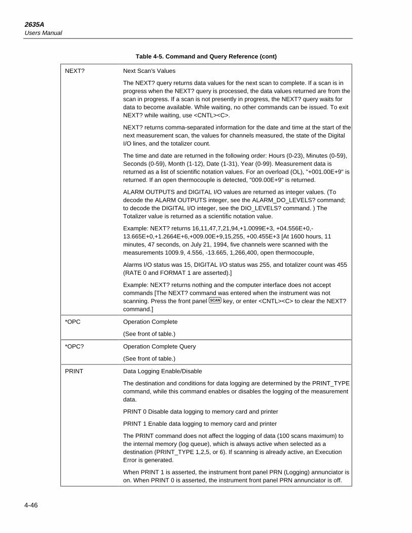
2635AUsers Manual
4-46
Table 4-5. Command and Query Reference (cont)
NEXT? Next Scan’s Values
The NEXT? query returns data values for the next scan to complete. If a scan is inprogress when the NEXT? query is processed, the data values returned are from thescan in progress. If a scan is not presently in progress, the NEXT? query waits fordata to become available. While waiting, no other commands can be issued. To exitNEXT? while waiting, use <CNTL><C>.
NEXT? returns comma-separated information for the date and time at the start of thenext measurement scan, the values for channels measured, the state of the DigitalI/O lines, and the totalizer count.
The time and date are returned in the following order: Hours (0-23), Minutes (0-59),Seconds (0-59), Month (1-12), Date (1-31), Year (0-99). Measurement data isreturned as a list of scientific notation values. For an overload (OL), "+001.00E+9" isreturned. If an open thermocouple is detected, "009.00E+9" is returned.
ALARM OUTPUTS and DIGITAL I/O values are returned as integer values. (Todecode the ALARM OUTPUTS integer, see the ALARM_DO_LEVELS? command;to decode the DIGITAL I/O integer, see the DIO_LEVELS? command. ) TheTotalizer value is returned as a scientific notation value.
Example: NEXT? returns 16,11,47,7,21,94,+1.0099E+3, +04.556E+0,-13.665E+0,+1.2664E+6,+009.00E+9,15,255, +00.455E+3 [At 1600 hours, 11minutes, 47 seconds, on July 21, 1994, five channels were scanned with themeasurements 1009.9, 4.556, -13.665, 1,266,400, open thermocouple,
Alarms I/O status was 15, DIGITAL I/O status was 255, and totalizer count was 455(RATE 0 and FORMAT 1 are asserted).]
Example: NEXT? returns nothing and the computer interface does not acceptcommands [The NEXT? command was entered when the instrument was notscanning. Press the front panel Q key, or enter <CNTL><C> to clear the NEXT?command.]
*OPC Operation Complete
(See front of table.)
*OPC? Operation Complete Query
(See front of table.)
PRINT Data Logging Enable/Disable
The destination and conditions for data logging are determined by the PRINT_TYPEcommand, while this command enables or disables the logging of the measurementdata.
PRINT 0 Disable data logging to memory card and printer
PRINT 1 Enable data logging to memory card and printer
The PRINT command does not affect the logging of data (100 scans maximum) tothe internal memory (log queue), which is always active when selected as adestination (PRINT_TYPE 1,2,5, or 6). If scanning is already active, an ExecutionError is generated.
When PRINT 1 is asserted, the instrument front panel PRN (Logging) annunciator ison. When PRINT 0 is asserted, the instrument front panel PRN annunciator is off.
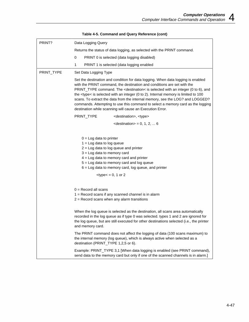
Computer OperationsComputer Interface Commands and Operation 4
4-47
Table 4-5. Command and Query Reference (cont)
PRINT? Data Logging Query
Returns the status of data logging, as selected with the PRINT command.
0 PRINT 0 is selected (data logging disabled)
1 PRINT 1 is selected (data logging enabled
PRINT_TYPE Set Data Logging Type
Set the destination and condition for data logging. When data logging is enabledwith the PRINT command, the destination and conditions are set with thePRINT_TYPE command. The <destination< is selected with an integer (0 to 6), andthe <type< is selected with an integer (0 to 2). Internal memory is limited to 100scans. To extract the data from the internal memory, see the LOG? and LOGGED?commands. Attempting to use this command to select a memory card as the loggingdestination while scanning will cause an Execution Error.
PRINT_TYPE <destination>, <type>
<destination> = 0, 1, 2, ... 6
0 = Log data to printer1 = Log data to log queue2 = Log data to log queue and printer3 = Log data to memory card4 = Log data to memory card and printer5 = Log data to memory card and log queue6 = Log data to memory card, log queue, and printer
<type< = 0, 1 or 2
0 = Record all scans1 = Record scans if any scanned channel is in alarm2 = Record scans when any alarm transitions
When the log queue is selected as the destination, all scans area automaticallyrecorded in the log queue as if type 0 was selected. types 1 and 2 are ignored forthe log queue, but are still executed for other destinations selected (i.e., the printerand memory card.
The PRINT command does not affect the logging of data (100 scans maximum) tothe internal memory (log queue), which is always active when selected as adestination (PRINT_TYPE 1,2,5 or 6).
Example: PRINT_TYPE 3,1 [When data logging is enabled (see PRINT command),send data to the memory card but only if one of the scanned channels is in alarm.]

2635AUsers Manual
4-48
Table 4-5. Command and Query Reference (cont)
PRINT_TYPE? Data Logging Type Query
Returns the status of data logging destination and condition, as selected with thePRINT_TYPE command. Returns two integers in the form <destination<,<type> asfollows:
<destination> = 0, 1, 2, ... 6
0 = Log data to printer1 = Log data to internal memory2 = Log data to internal memory and printer3 = Log data to memory card4 = Log data to memory card and printer5 = Log data to memory card and internal memory6 = Log data to memory card, internal memory, and printer
<type< = 0, 1 or 2
0 = Record all scans1 = Record scans if any scanned channel is in alarm2 = Record scans when any alarm transitions
Example: PRINT_TYPE? returns 5,0 [Destination for logged data is to the memorycard and internal memory, and all scans are recorded.]
RANGE? Channel Range Query
Returns the range(s) used for the scan in progress or the last completed scan. If achannel is configured for autoranging, the actual range used for the measurement isreturned.
RANGE? <channel>
<channel> = 0, 1, 2, ... 20, or leave blank
If the <channel> specification field is left blank, values for all defined channels arereturned. An Execution Error results if a request is made for a channel defined asOFF, the channel specified is invalid, or if the channel has been set up but notmeasured with at least one scan. The range value returned is not affected by Mx+Bscaling.
An integer value (1-6) is returned, based on the table below. Temperature functions(thermocouple and RTD) always return a 1. Commas separate the integers if thereturn is for all scanned channels.
RANGE VOLTAGE OHMS FREQUENCY
1 300 mV 300e 900 Hz2 3 V 3 ke 9 kHz3 30 V 30 ke 90 kHz4 150/300 V* 300 ke 900 kHz5 90 mV** 3 Me 1 Mhz6 900 mV** 10 Me
*300 V only on channels 0 and 11.
**Volts DC only.Example: RANGE? 12 returns 3 [Channel 12 has a range of 3. If measuring voltage,it would indicate the 30V scale.].Example: RANGE? returns 2,2,1,6 [Four channels were scanned. The first andsecond have a range of 2, the third a range of 1, and the fourth a range of 6.]

Computer OperationsComputer Interface Commands and Operation 4
4-49
Table 4-5. Command and Query Reference (cont)
RATE Select Measurement Rate
Specifies the measurement rate. Changing the measurement rate also clears theReview array, and ALARM OUTPUTS and DIGITAL I/O lines.
RATE 0 Selects the slow measurement rate.
RATE 1 Selects the fast measurement rate.
Selection of the fast measurement rate using the RATE 1 command will speed upthe measurement portion of the scan interval; however, the measurement resolutionis four digits instead of five digits. For example, a reading of +115.32 with a slowmeasurement rate would be +115.3 with the fast measurement rate. An ExecutionError is generated if the argument is not 0 or 1 or if the instrument is scanning.
RATE? Measurement Rate Query
Return measurement rate for the instrument.
0 Measurement rate is slow
1 Measurement rate is fast
REMS Remote without Lockout
Places the instrument in the remote mode, lights the front panel REM annunciator,and only two front panel keys are active (with special REMS functionality):
The Q key triggers a single scan.
The K key returns the instrument to normal front panel control.
To return the instrument to normal front panel control with a command, use theLOCS command.
REVIEW_CLR Clear Review Values
Clear all minimum, maximum, and last values (all channels) in the Review array. (Itis not possible to selectively clear individual entries in the Review array.) The Reviewclearing operation is carried out at any time, except during the measurement portionof the scan internal. only at the completion of any scan in progress. Clearing theReview array also clears ALARM OUTPUTS and DIGITAL I/O lines to a logic high..
*RST Reset
(See front of table.)
RTD_R0 RTD Ice Point (R0)
For the indicated channel, store the numeric data as the RTD R0 ice pointresistance, i.e., the resistance of the RTD at 32°F (0°C). Changing the ice point alsoclears the Review array and ALARM OUTPUTS and DIGITAL I/O lines. (The 0portion of R0 in the RTD_R0 command is the number zero.) The default value is100.00.
RTD_R0 <channel<, <R0>
<channel> = 0,1,2 ... 20
<R0> = 000.00 to 999.99
An Execution Error is generated if the R0 value supplied is not within the indicatedrange, the channel specified is invalid, the channel is defined as OFF, ormeasurements are active.
Example: RTD_R0 6, 124.85 [For channel 6, set the R0 ice point resistance to avalue of 124.85.]

2635AUsers Manual
4-50
Table 4-5. Command and Query Reference (cont)
RTD_R0? RTD Ice-Point (R0) Query
Returns the RTD R0 (ice-point resistance) value for the indicated channel. (The 0portion of R0 in the RTD_R0 command is the number zero.)
RTD_R0? <channel>
<channel< = 0,1,2, ... 20
If the channel number is invalid, an Execution Error is generated. If a channel isdefined OFF, or if no change has been made to R0 for a channel, the value"+100.00E+0" (default) is returned.
RWLS Remote with Lockout (RS-232 only)
Enter the IEEE-488.1 remote with front panel lockout (RWLS) state. All front panelbuttons are disabled, and the REM annunciator is lit.
If this command is used with the IEEE-488 interface, an Execution Error isgenerated.
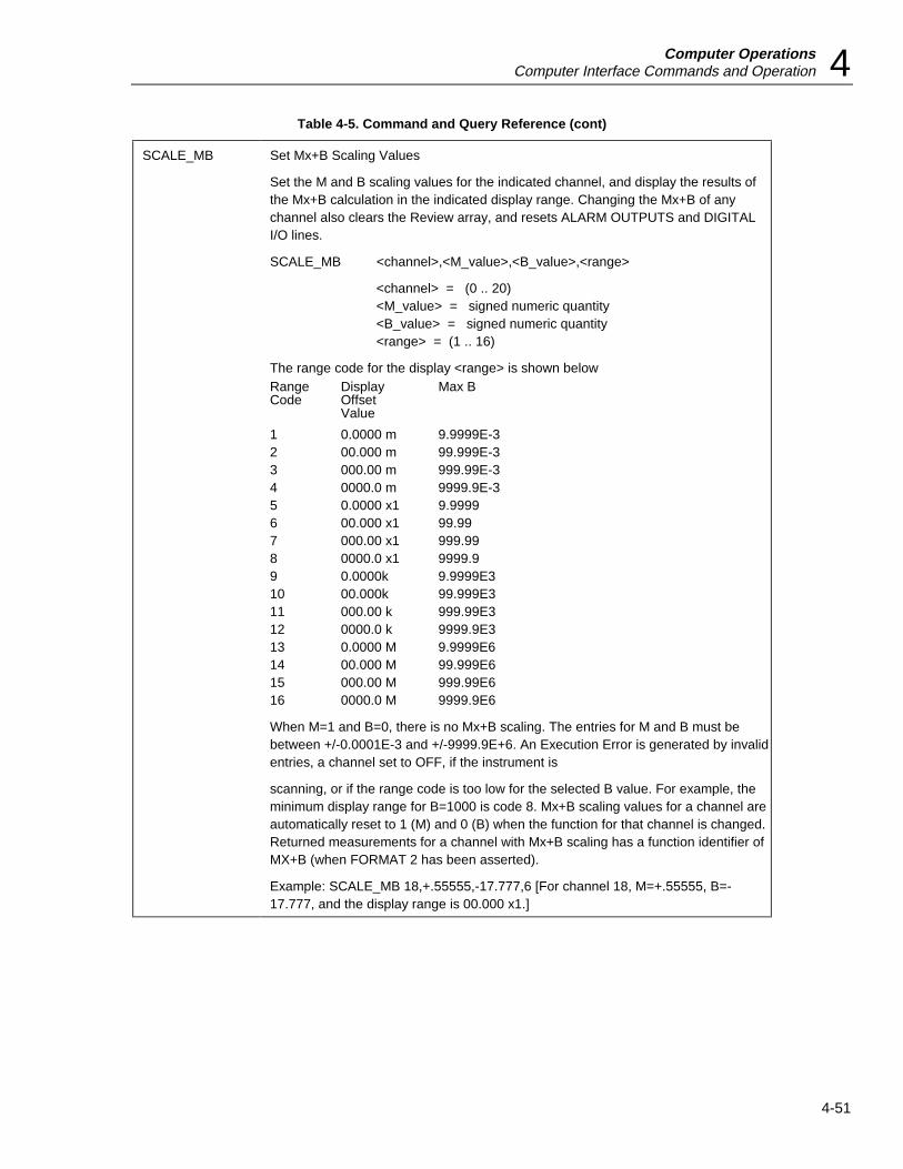
Computer OperationsComputer Interface Commands and Operation 4
4-51
Table 4-5. Command and Query Reference (cont)
SCALE_MB Set Mx+B Scaling Values
Set the M and B scaling values for the indicated channel, and display the results ofthe Mx+B calculation in the indicated display range. Changing the Mx+B of anychannel also clears the Review array, and resets ALARM OUTPUTS and DIGITALI/O lines.
SCALE_MB <channel>,<M_value>,<B_value>,<range>
<channel> = (0 .. 20)<M_value> = signed numeric quantity<B_value> = signed numeric quantity<range> = (1 .. 16)
The range code for the display <range> is shown belowRange Display Max BCode Offset
Value
1 0.0000 m 9.9999E-32 00.000 m 99.999E-33 000.00 m 999.99E-34 0000.0 m 9999.9E-35 0.0000 x1 9.99996 00.000 x1 99.997 000.00 x1 999.998 0000.0 x1 9999.99 0.0000k 9.9999E310 00.000k 99.999E311 000.00 k 999.99E312 0000.0 k 9999.9E313 0.0000 M 9.9999E614 00.000 M 99.999E615 000.00 M 999.99E616 0000.0 M 9999.9E6
When M=1 and B=0, there is no Mx+B scaling. The entries for M and B must bebetween +/-0.0001E-3 and +/-9999.9E+6. An Execution Error is generated by invalidentries, a channel set to OFF, if the instrument is
scanning, or if the range code is too low for the selected B value. For example, theminimum display range for B=1000 is code 8. Mx+B scaling values for a channel areautomatically reset to 1 (M) and 0 (B) when the function for that channel is changed.Returned measurements for a channel with Mx+B scaling has a function identifier ofMX+B (when FORMAT 2 has been asserted).
Example: SCALE_MB 18,+.55555,-17.777,6 [For channel 18, M=+.55555, B=-17.777, and the display range is 00.000 x1.]

2635AUsers Manual
4-52
Table 4-5. Command and Query Reference (cont)
SCALE_MB? Mx+B Scaling Values Query
Return the M and B scaling values for the indicated channel.
SCALE_MB? <channel>
<channel> = 0, ... 20
This command returns three values. The first two are the M and B values for thechannel indicated, even when M=1 and B=0 or the channel function is defined asOFF. These first two values are returned in M and B order and in scientific notationformat with five digits of resolution. The third value returned indicates the Mx+Bdisplay range. The Mx+B scaling values are automatically reset to 1 (M) and 0 (B)when the function for that channel is changed.
The range code for the display <range> is shown below:Range Display Max BCode Offset
Value
1 0.0000 m 9.9999E-32 00.000 m 99.999E-33 000.00 m 999.99E-34 0000.0 m 9999.9E-35 0.0000 x1 9.99996 00.000 x1 99.997 000.00 x1 999.998 0000.0 x1 9999.99 0.0000k 9.9999E310 00.000k 99.999E311 000.00 k 999.99E312 0000.0 k 9999.9E313 0.0000 M 9.9999E614 00.000 M 99.999E615 000.00 M 999.99E616 0000.0 M 9999.9E6
Example: SCALE_MB? 0 returns +1.0000E+0,-1.0000E+3,9 [For channel 0, M=1,B=-1000, and the display range is 0.0000 k.]
SCAN Enable/Disable Scanning
This command performs the same function as Q on the front panel.
SCAN 1 Enable scanning.SCAN 0 Disable scanning
If SCAN 0 is set during the measurement interval of the scan, the measurementportion is completed. If SCAN 0 is set during the countdown interval of the scan, thescan is immediately terminated.
If there are no configured channels (all are defined as OFF) or values other than 0 or1 are given, an Execution Error is generated.
The MON and SCAN commands work in conjunction with the front panel controls.The Monitor and Scan functions can be enabled or disabled from either the frontpanel or the computer interface. The most recently specified monitor channel (fromfront panel or computer interface) becomes the one channel monitored.
Front panel Q and M buttons work only when the lockout state is “local withoutlockout” (see the LOCS command)..
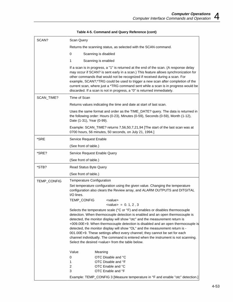
Computer OperationsComputer Interface Commands and Operation 4
4-53
Table 4-5. Command and Query Reference (cont)
SCAN? Scan Query
Returns the scanning status, as selected with the SCAN command.
0 Scanning is disabled
1 Scanning is enabled
If a scan is in progress, a "1" is returned at the end of the scan. (A response delaymay occur if SCAN? is sent early in a scan.) This feature allows synchronization forother commands that would not be recognized if received during a scan. Forexample, SCAN?;*TRG could be used to trigger a new scan after completion of thecurrent scan, where just a *TRG command sent while a scan is in progress would bediscarded. If a scan is not in progress, a "0" is returned immediately.
SCAN_TIME? Time of Scan
Returns values indicating the time and date at start of last scan.
Uses the same format and order as the TIME_DATE? query. The data is returned inthe following order: Hours (0-23), Minutes (0-59), Seconds (0-59), Month (1-12),Date (1-31), Year (0-99).
Example: SCAN_TIME? returns 7,56,50,7,21,94 [The start of the last scan was at0700 hours, 56 minutes, 50 seconds, on July 21, 1994.]
*SRE Service Request Enable
(See front of table.)
*SRE? Service Request Enable Query
(See front of table.)
*STB? Read Status Byte Query
(See front of table.)
TEMP_CONFIG Temperature Configuration
Set temperature configuration using the given value. Changing the temperatureconfiguration also clears the Review array, and ALARM OUTPUTS and DITGITALI/O lines.
TEMP_CONFIG <value><value> = 0. 1, 2 , 3
Selects the temperature scale (°C or °F) and enables or disables thermocoupledetection. When thermocouple detection is enabled and an open thermocouple isdetected, the monitor display will show "otc" and the measurement return is+009.00E+9. When thermocouple detection is disabled and an open thermocouple isdetected, the monitor display will show "OL" and the measurement return is -001.00E+9. These settings affect every channel; they cannot be set for eachchannel individually. The command is entered when the instrument is not scanning.Select the desired <value> from the table below.
Value Meaning
0 OTC Disable and °C1 OTC Disable and °F2 OTC Enable and °C3 OTC Enable and °F
Example: TEMP_CONFIG 3 [Measure temperature in °F and enable "otc" detection.]

2635AUsers Manual
4-54
Table 4-5. Command and Query Reference (cont)
TEMP_CONFIG? Temperature Configuration Query
Returns the status of the temperature configuration, as selected with theTEMP_CONFIG command. Returns an integer 0, 1, 2, or 3, which corresponds tothe temperature configuration, as shown in the table below.
Value Meaning
0 OTC Disable and °C1 OTC Disable and °F2 OTC Enable and °C3 OTC Enable and °F
Example: TEMP_CONFIG? returns 2 [“otc” detection is enabled and the temperaturescale is °C.]
TIME Set the instrument time.
TIME <hours>,<minutes>
<hours> = (0 .. 23) (24-hour scale, 18:00 = 6:00 pm).<minutes> = (0 .. 59)
[seconds] = (0, ... 59)
Invalid values generate an Execution Error. The [seconds] field can be left blank,automatically entering 00.
Example: TIME 16,30,15 [Set the clock for 1600 hours (4 pm), 30 minutes, and 15seconds.]
TIME_DATE? Retrieve Time and Date
Returns comma-separated integer values for time, date, and year using the followingformat:
hours 0-23minutes 0-59seconds 0-59month 1-12day 1-31year 00-99
The TIME command is used to set hours, minutes, and seconds.
Example: TIME_DATE? returns 2, 43, 12, 7, 21, 94 [The time is 0200 hours, 43minutes, 12 seconds, on July 21, 1994
TOTAL Set Totalizer Count
Give the Totalizer count a new initial value.
TOTAL <t_value><t_value> = (0 .. 65535)
If the value is not in the range 0 through 65,535, an Execution Error is generated.Setting the totalizer count also clears the Totalize Overflow bit in the InstrumentEvent Register (see Figure 4-3). Clear the Totalizer count by setting the Totalizer tozero (0).
Example: TOTAL 12000 [Set the totalizer count to 12000 Clear the Totalizer countby setting the Totalizer to zero (0).

Computer OperationsComputer Interface Commands and Operation 4
4-55
Table 4-5. Command and Query Reference (cont)
TOTAL? Totalizer Value Query
Returns the value of the present Totalizer count. Format of the value is +00.000E+3.When the Totalizer has overflowed, the value returned is +001.00E+9.
Example: TOTAL? returns 13.465E+3 [The present value of the totalizer count is13,465.]
TOTAL_DBNC Set Totalizing Debounce
Set totalizing input debounce state, which adds a delay of 1.75 ms to each transition,allowing increased accuracy from totalizer inputs from contact closures.
TOTAL_DBNC <dbnc_state><dbnc_state> = 1 (on) 0 (off)
Use of any other value causes an Execution Error to be generated. At initial powerup, totalize debounce is disabled (0). An Execution Error is generated if the totalizerdebouhce setting is changed when scanning while logging to the memory card isenabled.
TOTAL_DBNC? Totalizer Debounce Query
Returns the totalizing input’s debounce state, as selected with the TOTAL_DBNCcommand.
0 Debounce is off
1 Debounce is on
*TRG SIngle-Scan Trigger
(See front of table.)
TRIGGER Select Trigger Type
Select the type of scan triggering option. The use of a trigger option has the sameeffect as pressing the front panel Q key. An input for an external trigger isavailable at the ALARM OUTPUTS connector on the rear panel of the instrument,pins TR and GROUND (TRIGGER 1). Scanning can also be enabled when amonitored channel goes into alarm (TRIGGER 2).
TRIGGER 0 External trigger and Alarm trigger disabled
TRIGGER 1 External trigger enabled
TRIGGER 2 Alarm trigger enabled
TRIGGER 0 means external triggering is disabled and only normal scan intervaltriggering can be used. If this command is entered during scanning while logging tothe memory card, an Execution Error is generated.
TRIGGER 1 means that external triggering is enabled. An acceptable low input (-0.6to +0.8V dc) between the pins TR and GROUND on the ALARM OUTPUTSconnector on the rear panel will cause the instrument to start scanning. When theTR input returns to logic high, scanning is disabled. External trigger inputs during ascan are ignored.
TRIGGER 2 means the alarm trigger is enabled. When a channel being monitoredgoes into alarm, the instrument starts scanning. When the channel being monitoredgoes out of alarm, the instrument stops scanning. The *TRG and GET commandscan be used with a trigger option selection.
If the trigger type given is not one of the listed values, an Execution Error isgenerated.

2635AUsers Manual
4-56
Table 4-5. Command and Query Reference (cont)
TRIGGER? Trigger Type Query
Returns an integer representing the present trigger type:
0 External trigger and Alarm trigger disabled1 External trigger enabled2 Alarm trigger enabled
*TST? Self Test Query
(See front of table.)
*WAI Wait-to-continue
(see front of table)
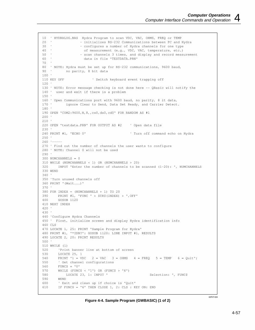
Computer OperationsComputer Interface Commands and Operation 4
4-57
10 ' HYDRALOG.BAS Hydra Program to scan VDC, VAC, OHMS, FREQ or TEMP20 ' - initializes RS-232 Communications between PC and Hydra30 ' - configures a number of Hydra channels for one type40 ' of measurement (e.g., VDC, VAC, temperature, etc.)50 ' - scan channels 3 times, and display and record measurement60 ' data in file "TESTDATA.PRN"70 '80 ' NOTE: Hydra must be set up for RS-232 communications, 9600 baud,90 ' no parity, 8 bit data100 '110 KEY OFF ' Switch keyboard event trapping off120 '130 ' NOTE: Error message checking is not done here -- QBasic will notify the140 ' user and exit if there is a problem150 '160 ' Open Communications port with 9600 baud, no parity, 8 it data,170 ' ignore Clear to Send, Data Set Ready, and Carrier Detect. 180 '190 OPEN "COM2:9600,N,8,,cs0,ds0,cd0" FOR RANDOM AS #1200 '210 '220 OPEN "testdata.PRN" FOR OUTPUT AS #2 ' Open data file230 '240 PRINT #1, "ECHO 0" ' Turn off command echo on Hydra250 '260 '-----270 ' Find out the number of channels the user wants to configure280 ' NOTE: Channel 0 will not be used290 '300 NUMCHANNELS = 0310 WHILE (NUMCHANNELS < 1) OR (NUMCHANNELS > 20)320 INPUT "Enter the number of channels to be scanned (1-20): ", NUMCHANNELS330 WEND340 '350 'Turn unused channels off360 PRINT "(Wait...)"370 '380 FOR INDEX = (NUMCHANNELS + 1) TO 20390 PRINT #1, "FUNC " + STR$(INDEX) + ",OFF"400 GOSUB 1120410 NEXT INDEX420 '430 '440 'Configure Hydra Channels450 ' First, initialize screen and display Hydra identification info460 CLS470 LOCATE 1, 25: PRINT "Sample Program for Hydra"480 PRINT #1, "*IDN?": GOSUB 1120: LINE INPUT #1, RESULT$490 LOCATE 2, 20: PRINT RESULT$500 '510 WHILE (1)520 'Print banner line at bottom of screen530 LOCATE 25, 1540 PRINT "1 = VDC 2 = VAC 3 = OHMS 4 = FREQ 5 = TEMP 6 = Quit";550 ' Get channel configurations560 FUNC$ = "0"570 WHILE (FUNC$ < "1") OR (FUNC$ > "6")580 LOCATE 23, 1: INPUT " Selection: ", FUNC$590 WEND600 ' Exit and clean up if choice is "Quit"610 IF FUNC$ = "6" THEN CLOSE 1, 2: CLS : KEY ON: END
op51f.eps
Figure 4-4. Sample Program (GWBASIC) (1 of 2)

2635AUsers Manual
4-58
620 '630 ' Set up the common channel configuration string (function and range)640 IF (FUNC$ = "1") THEN CONFIG$ = "VDC, 1"650 IF (FUNC$ = "2") THEN CONFIG$ = "VAC, 1"660 IF (FUNC$ = "3") THEN CONFIG$ = "OHMS, 1, 2" ' Assuming 2-terminal channel670 IF (FUNC$ = "4") THEN CONFIG$ = "FREQ, 1"680 IF (FUNC$ = "1") THEN CONFIG$ = "TEMP, K" ' Assuming K thermocouple690 '700 'Set up Hydra / Configure channels710 LOCATE 23, 1: PRINT "Programming Hydra...";720 FOR INDEX = 1 TO NUMCHANNELS730 PRINT #1, "FUNC " + STR$(INDEX) + "," + CONFIG$740 GOSUB 1120750 NEXT INDEX760 '770 LOCATE 23, 1: PRINT "Measuring " + CONFIG$ + " "780 '790 ' Scan three times800 FOR INDEX = 1 TO 3810 PRINT #1, "*TRG" ' Start a single scan820 GOSUB 1120 ' Get prompt back from Hydra830 PRINT #1, "SCAN_TIME?": GOSUB 1120840 LINE INPUT #1, RESULT$ ' Get scan time stamp850 PRINT #2, RESULT$ ' Save time stamp to data file860 FOR CHANNELINDEX = 1 TO NUMCHANNELS ' Get scan data870 PRINT #1, "LAST? " + STR$(CHANNELINDEX) ' Request channel data880 GOSUB 1120890 INPUT #1, RESULT$ ' Get channel result900 LOCATE CHANNELINDEX + 2, 25910 PRINT "Chan " + STR$(CHANNELINDEX) + ": ";920 PRINT RESULT$ ' Print results to screen930 PRINT #2, RESULT$ + ","; ' Print results to data file940 NEXT CHANNELINDEX950 PRINT #2, "" ' End of line to data file960 NEXT INDEX970 WEND980 END990 '1000 '1010 '1020 '1030 ' CHECKRESPONSE Subroutine1040 ' This subroutine checks the Hydra prompt after sending a command to1050 ' Hydra, to see if an error occurred1060 ' 1070 ' The possible responses are:1080 ' "=>(CR)(LF)" (command successful)1090 ' "?>(CR)(LF)" (command syntax error)1100 ' "!>(CR)(LF)" (command execution error)1110 '1120 PROMPT$ = INPUT$(4, #1) ' Get prompt1130 IF INSTR(1, PROMPT$, "=>") <> 0 THEN RETURN 'Command successful1140 IF INSTR(1, PROMPT$, "?>") <> 0 THEN1150 PRINT "Command Syntax Error!"1160 ELSEIF INSTR(1, PROMPT$, "!>") <> 0 THEN1170 PRINT "Command Execution Error!"1180 END IF1190 '1200 PRINT "Program execution halted due to communications errors"1210 END
op51_1f.eps
Figure 4-5. Sample Program (GWBASIC) (2 of 2)
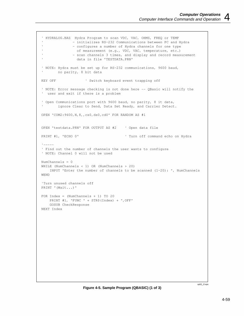
Computer OperationsComputer Interface Commands and Operation 4
4-59
' HYDRALOG.BAS Hydra Program to scan VDC, VAC, OHMS, FREQ or TEMP' - initializes RS-232 Communications between PC and Hydra' - configures a number of Hydra channels for one type' of measurement (e.g., VDC, VAC, temperature, etc.)' - scan channels 3 times, and display and record measurement' data in file "TESTDATA.PRN"
' NOTE: Hydra must be set up for RS-232 communications, 9600 baud,' no parity, 8 bit data
KEY OFF ' Switch keyboard event trapping off
' NOTE: Error message checking is not done here -- QBasic will notify the' user and exit if there is a problem
' Open Communications port with 9600 baud, no parity, 8 it data,' ignore Clear to Send, Data Set Ready, and Carrier Detect.
OPEN "COM2:9600,N,8,,cs0,ds0,cd0" FOR RANDOM AS #1
OPEN "testdata.PRN" FOR OUTPUT AS #2 ' Open data file
PRINT #1, "ECHO 0" ' Turn off command echo on Hydra
'-----' Find out the number of channels the user wants to configure' NOTE: Channel 0 will not be used
NumChannels = 0WHILE (NumChannels < 1) OR (NumChannels > 20) INPUT "Enter the number of channels to be scanned (1-20): ", NumChannelsWEND
'Turn unused channels offPRINT "(Wait...)"
FOR Index = (NumChannels + 1) TO 20 PRINT #1, "FUNC " + STR$(Index) + ",OFF" GOSUB CheckResponseNEXT Index
op52_1f.eps
Figure 4-5. Sample Program (QBASIC) (1 of 3)

2635AUsers Manual
4-60
'Configure Hydra Channels' First, initialize screen and display Hydra identification infoCLSLOCATE 1, 25: PRINT "Sample Program for Hydra"PRINT #1, "*IDN?": GOSUB CheckResponse: LINE INPUT #1, Result$LOCATE 2, 20: PRINT Result$
WHILE (1) 'Print banner line at bottom of screen LOCATE 25, 1 PRINT "1 = VDC 2 = VAC 3 = OHMS 4 = FREQ 5 = TEMP 6 = Quit"; ' Get channel configurations Func$ = "0" WHILE (Func$ < "1") OR (Func$ > "6") LOCATE 23, 1: INPUT " Selection: ", Func$ WEND ' Exit and clean up if choice is "Quit" IF Func$ = "6" THEN CLOSE 1, 2: CLS : KEY ON: END
' Set up the common channel configuration string (function and range) SELECT CASE Func$ CASE "1" Config$ = "VDC, 1" CASE "2" Config$ = "VAC, 1" CASE "3" Config$ = "OHMS, 1, 2" ' Assuming 2-terminal channel CASE "4" Config$ = "FREQ, 1" CASE "5" Config$ = "TEMP, K" ' Assuming K thermocouple END SELECT
'Set up Hydra / Configure channels LOCATE 23, 1: PRINT "Programming Hydra..."; FOR Index = 1 TO NumChannels PRINT #1, "FUNC " + STR$(Index) + "," + Config$ GOSUB CheckResponse NEXT Index
LOCATE 23, 1: PRINT "Measuring " + Config$ + " "
' Scan three times FOR Index = 1 TO 3 PRINT #1, "*TRG" ' Start a single scan GOSUB CheckResponse ' Get prompt back from Hydra PRINT #1, "SCAN_TIME?": GOSUB CheckResponse LINE INPUT #1, Result$ ' Get scan time stamp PRINT #2, Result$ ' Save time stamp to data file FOR ChannelIndex = 1 TO NumChannels ' Get scan data PRINT #1, "LAST? " + STR$(ChannelIndex) ' Request channel data GOSUB CheckResponse INPUT #1, Result$ ' Get channel result LOCATE ChannelIndex + 2, 25 PRINT "Chan " + STR$(ChannelIndex) + ": "; PRINT Result$ ' Print results to screen PRINT #2, Result$ + ","; ' Print results to data file NEXT ChannelIndex PRINT #2, "" ' End of line to data file NEXT IndexWENDEND
op52_2f.eps
Figure 4-6. Sample Program (QBASIC)(2 of 3)
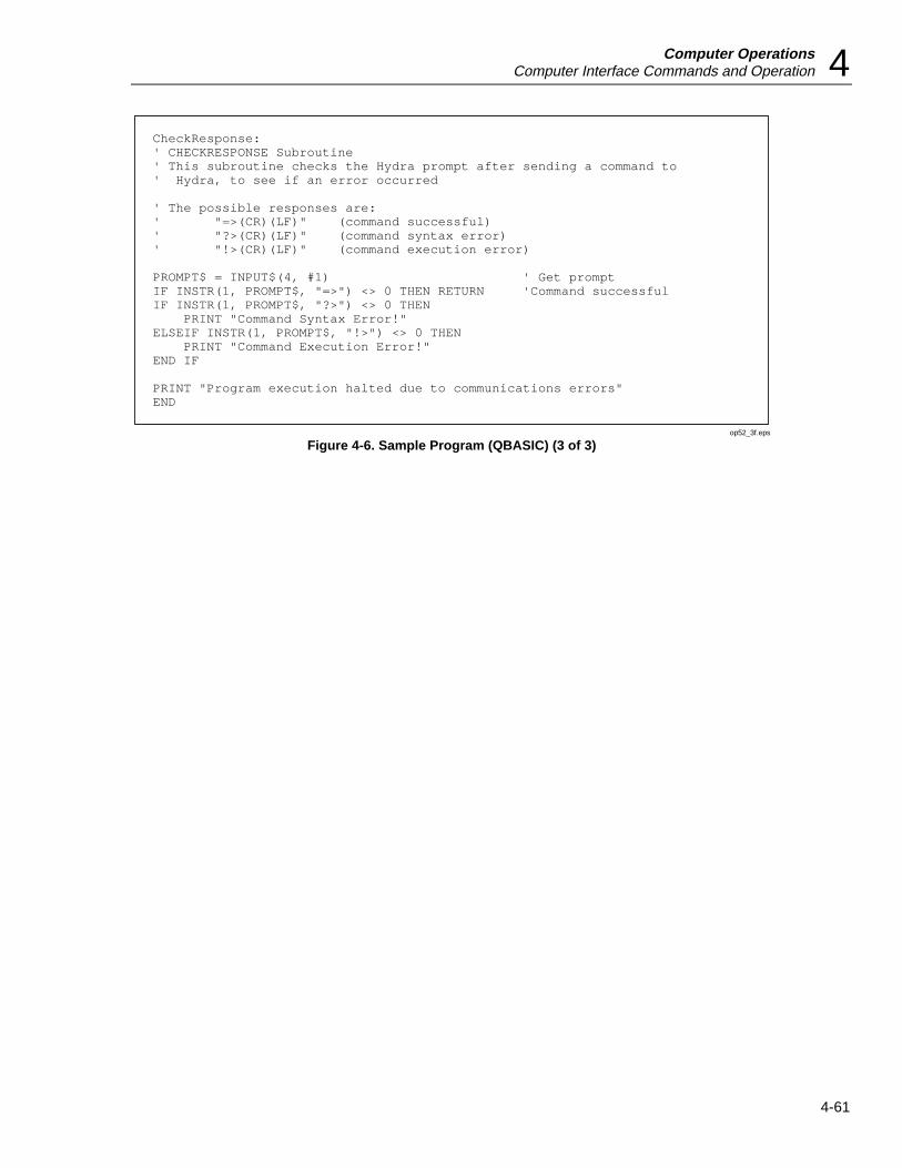
Computer OperationsComputer Interface Commands and Operation 4
4-61
CheckResponse:' CHECKRESPONSE Subroutine' This subroutine checks the Hydra prompt after sending a command to' Hydra, to see if an error occurred ' The possible responses are:' "=>(CR)(LF)" (command successful)' "?>(CR)(LF)" (command syntax error)' "!>(CR)(LF)" (command execution error)
PROMPT$ = INPUT$(4, #1) ' Get promptIF INSTR(1, PROMPT$, "=>") <> 0 THEN RETURN 'Command successfulIF INSTR(1, PROMPT$, "?>") <> 0 THEN PRINT "Command Syntax Error!"ELSEIF INSTR(1, PROMPT$, "!>") <> 0 THEN PRINT "Command Execution Error!"END IF
PRINT "Program execution halted due to communications errors"END
op52_3f.eps
Figure 4-6. Sample Program (QBASIC) (3 of 3)

2635AUsers Manual
4-62
/* * HYDRALOG.C Hydra Program to scan VDC, VAC, OHMS, FREQ or TEMP * - initializes RS-232 Communications between PC and Hydra * - configures a number of Hydra channels for one type * of measurement (e.g., VDC, VAC, temperature, etc.) * - scan channels 3 times, and display and record measurement * data on the screen and in file "testdata.prn" * * This program uses routines from the GreenLeaf Communications Library * (asiopen(), asiputs(), and asigets_timed()) for sending and receiving * information from the serial port connected to the Hydra. We recommend * the use of a third-party serial communications library when developing * C programs to communicate with Hydra instruments over PC serial ports. */
/* * NOTE: Hydra must be set up for RS-232 communications, 1200 baud, * no parity, 8 bit data */
#include <stdio.h>#include <string.h>#include <errno.h>
#include "asiports.h" /* Greenleaf CommLib include file */
static FILE *testdata; /* File handle for output data file */
main(argc,argv)int argc;char *argv[]; int ret_code; /* code returned by various GreenLeaf communications functions */
unsigned numChannels; /* Number of channels to be scanned */ unsigned index; /* counter */
char response[30]; /* Buffer for user response */ char sendbuff[129]; /* local buffer for transmitting to Hydra */ char recvbuff[129]; /* local buffer for receiving from Hydra */ /* Open and initialize COM2, the serial port the Hydra unit is attached to, for 1200 baud, no parity, 8 it data, and ignore DTR and CTS */
ret_code = asiopen( COM2, (ASINOUT | BINARY | NORMALRX), 1000, 1000, 1200L, P_NONE, 1,8,FALSE,FALSE ); if ( ret_code < ASSUCCESS ) fprintf(stderr,"Failed to open the port, Greenleaf error: %d.\n", ret_code ); exit(1);
/*send reset and uninstall */ asiputc (com2, '\x11'); asiputc (com2, '\x03'); checkResponse (); /* Get prompt */
op53_1f.eps
Figure 4-6. Sample Program (QuickC) (1of 5)

Computer OperationsComputer Interface Commands and Operation 4
4-63
asiputs( COM2, "ECHO 0", -2); /* Turn off command echo on Hydra */ checkResponse(); /* Get prompt */
/* Open data file TESTDATA.PRN */ if((testdata = fopen("testdata.prn","w")) == NULL) perror("Cannot open testdata.prn"); exit(1);
/* Find out the number of channels the user wants to configure NOTE: Channel 0 will not be used */
numChannels = 0; while((numChannels < 1) || (numChannels > 20)) fprintf(stdout,"Enter the number of channels to be scanned (1-20):"); gets(response); numChannels = atoi(response); /* convert ascii response to numeric */ /* Turn off unused channels */ fprintf(stdout,"\nWait....\n"); for(index = numChannels + 1; index < 21; ++index) sprintf(sendbuff,"FUNC %d, OFF",index); asiputs(COM2,sendbuff,-2); checkResponse(); /* get prompt */
/* Print Header and Hydra identification header */
fprintf(stdout,"\n\nSample Program for Hydra\n");
asiputs(COM2,"*IDN?",-2); /* Ask for Hydra identification info */ checkResponse(); /* Get prompt */ asigets_timed(COM2,recvbuff,256,-2,TICKS_PER_SECOND*2); /* Receive Hydra identification header */ fprintf(stdout,"%s\n\n",recvbuff); /* * Configure channels and scan until user chooses to Quit */ while(1) int func; /* Configuration setting */ char configStr[14]; /* channel function string */ /* * Configure Hydra Channels */
op53_2f.eps
Figure 4-7. Sample Program (QuickC) (2 of 5)

2635AUsers Manual
4-64
/* Request channel configuration from user */ fprintf(stdout,"1 = VDC\t\t2 = FAC\t\t3 = OHMS\t4 = FREQ\t5 = TEMP\t\t6 = Quit\n");
func = 0; do fprintf(stdout," Selection (1-6): "); gets(response); func = atoi(response); while((func < 1) || (func > 6));
if(func == 6) /* If Quit, exit program */ break; switch(func) /* set configuration string */ case 1: strcpy(configStr,"VDC,1"); break; case 2: strcpy(configStr,"VAC,1"); break; case 3: strcpy(configStr,"OHMS,1,2"); /* Assuming 2-terminal channel */ break; case 4: strcpy(configStr,"FREQ,1, 1"); break; case 5: strcpy(configStr,"TEMP, K"); /* Assuming K thermocouple */ break;
/* Send configuration to Hydra */ fprintf(stdout,"Programming Hydra...\n"); for(index = 1;index <= numChannels;++index) sprintf(sendbuff,"FUNC %d,%s",index,configStr); asiputs(COM2,sendbuff,-2); checkResponse(); /* get prompt */
op53_3f.eps
Figure 4-7. Sample Program (QuickC) (3 of 5)

Computer OperationsComputer Interface Commands and Operation 4
4-65
/* * Scan and receive data */ fprintf(stdout,"\nMeasuring %s...\n",configStr);
for(index=0;index < 3;++index) /* scan three times */ unsigned chanIndex; /* Channel counter */
asiputs(COM2,"*TRG",-2); /* trigger scan */ checkResponse(); /* get prompt */
asiputs(COM2,"SCAN_TIME?",-2); /* request time stamp for scan */ checkResponse(); /* get prompt */
/* receive time stamp for scan, and write to data file */ asigets_timed(COM2,recvbuff,256,-2,TICKS_PER_SECOND*2); fprintf(testdata,"%s\n",recvbuff);
for(chanIndex = 1; chanIndex <= numChannels; ++chanIndex) /* get value scanned for each channel */ sprintf(sendbuff,"LAST? %d",chanIndex); asiputs(COM2,sendbuff,-2); /* request value for channel */ checkResponse(); /* get prompt */
/* receive value for channel and write to screen and data file */ asigets_timed(COM2,recvbuff,256,-2,TICKS_PER_SECOND*2); fprintf(stdout,"Chan %d: %s, ",chanIndex,recvbuff); fprintf(testdata,"%s,",recvbuff); fprintf(stdout,"\n"); fprintf(testdata,"\n"); fprintf(stdout,"\n"); fprintf(testdata,"\n"); fclose(testdata); exit(0);
op53_4f.eps
Figure 4-7. Sample Program (QuickC)(4 of 5)
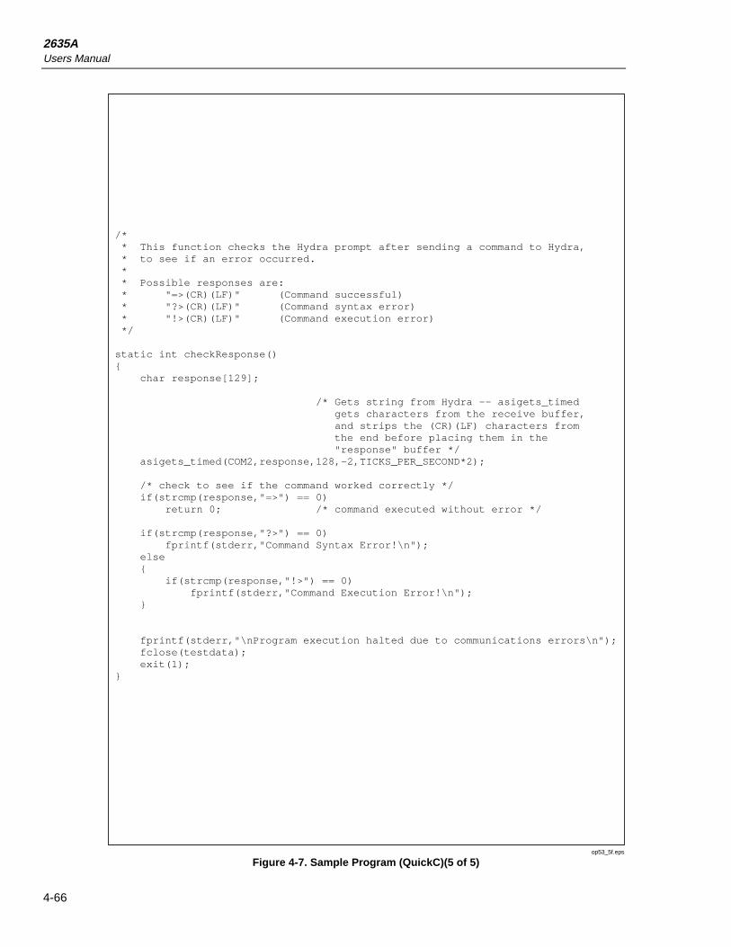
2635AUsers Manual
4-66
/* * This function checks the Hydra prompt after sending a command to Hydra, * to see if an error occurred. * * Possible responses are: * "=>(CR)(LF)" (Command successful) * "?>(CR)(LF)" (Command syntax error) * "!>(CR)(LF)" (Command execution error) */
static int checkResponse() char response[129]; /* Gets string from Hydra -- asigets_timed gets characters from the receive buffer, and strips the (CR)(LF) characters from the end before placing them in the "response" buffer */ asigets_timed(COM2,response,128,-2,TICKS_PER_SECOND*2);
/* check to see if the command worked correctly */ if(strcmp(response,"=>") == 0) return 0; /* command executed without error */
if(strcmp(response,"?>") == 0) fprintf(stderr,"Command Syntax Error!\n"); else if(strcmp(response,"!>") == 0) fprintf(stderr,"Command Execution Error!\n");
fprintf(stderr,"\nProgram execution halted due to communications errors\n"); fclose(testdata); exit(1);
op53_5f.eps
Figure 4-7. Sample Program (QuickC)(5 of 5)

5-1
Chapter 5Printer Operations
Title Page
Summary of Printer Operations......................................................................... 5-3Connecting the Instrument to a Printer.............................................................. 5-3Configuring for Printer Operations ................................................................... 5-5Printing Measurement Data and Memory Card Directory ................................ 5-6
Problems?...................................................................................................... 5-6Printing Measurement Results During Scanning .......................................... 5-6Printing the Review Array ............................................................................ 5-8Printing the Directory of the Memory Card.................................................. 5-9
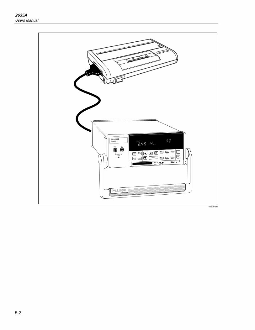
2635AUsers Manual
5-2
FUNC ALRM
Mx+B CANCEL ENTER
RATE
INTVL FILES REVIEW
SHIFT LIST TOTAL
SINGLE
TRIGS
SCAN
MON
CLOCK MODE CLEAR
LOCAL COMM ZERO
mAmVDCAC
k Hz
REVIEWLASTHYDRA DATA BUCKET
300VMAX
COM V
M
CH
BUSY BATT
op83f.eps
Printer OperationsSummary of Printer Operations 5
5-3
Summary of Printer OperationsPrinter operations allow an RS-232 connection between the instrument and a printer toprint out measurement results during scanning, the Review array, and a directory of thememory card files. The printer must accept a serial data input, either directly or via aserial-to-parallel converter. Measurement data recorded onto the memory card cannot beprinted out from the instrument (see Memory Card Operations, Chapter 3). Theinformation in this chapter is provided in three parts:
• Connecting the Instrument to a Printer
• Configuring for Printer Operations
• Printing Measurement Data and Memory Card Directory
Connecting the Instrument to a PrinterThe two most common configurations for connecting the instrument to a printer areshown in Figure 5-1. Printers with an RS-232 serial data interface may be used directly,while printers with a parallel input require a serial-to-parallel converter. For otherconfigurations, refer to your printer manual. A complete discussion of RS-232connections and cables, including cable fabrication information, is provided in AppendixD.
NoteSeveral printers use cables that have a DB-25 connector at one end. Thisdoes not necessarily indicate connectivity with the instrument RS-232 port.Examples include parallel interface printer cables, and 8-pin mini-circularcables. Check your printer manual before making any connections if thereis doubt about the interface.
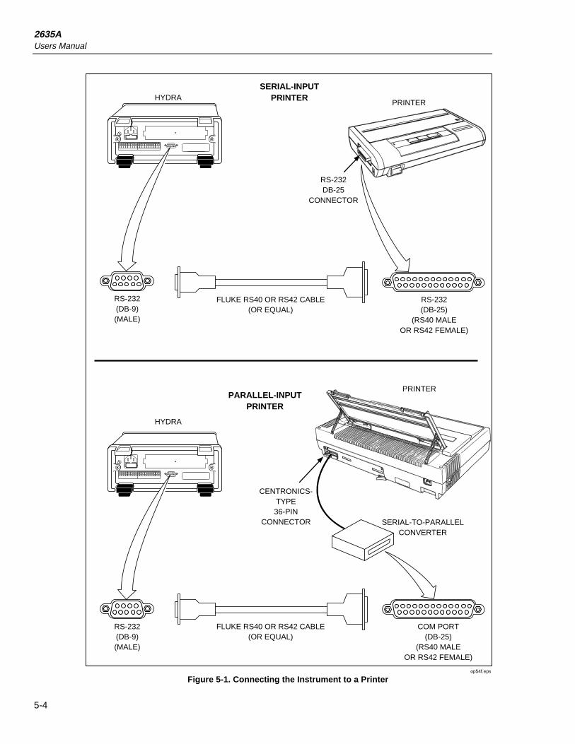
2635AUsers Manual
5-4
RS-232(DB-9)(MALE)
SERIAL-INPUTPRINTER
RS-232(DB-9)(MALE)
COM PORT(DB-25)
(RS40 MALEOR RS42 FEMALE)
FLUKE RS40 OR RS42 CABLE(OR EQUAL)
PARALLEL-INPUTPRINTER
HYDRA
PRINTER
HYDRAPRINTER
RS-232(DB-25)
(RS40 MALEOR RS42 FEMALE)
FLUKE RS40 OR RS42 CABLE(OR EQUAL)
RS-232DB-25
CONNECTOR
CENTRONICS-TYPE36-PIN
CONNECTOR SERIAL-TO-PARALLELCONVERTER
op54f.eps
Figure 5-1. Connecting the Instrument to a Printer

Printer OperationsConfiguring for Printer Operations 5
5-5
Configuring for Printer OperationsCorrect operation of the instrument RS-232 link with a printer depends on the linkparameters baud rate, parity, and CTS (Clear To Send). Perform the procedure in Figure5-3 to establish communication link parameters. Refer to your printer manual forinformation on selecting identical parameters for the printer, usually through the settingof DIP (dual in-line package) switches (with the printer unpowered). The instrument usesa fixed one start bit and one stop bit.
SHIFT
LIST38400192009600480024001200600300
bAUd
ENTER
ENTER
PAR
noEOdd
ENTER
Echo
OnOFF
CtS
OnOFF
ENTER
Typical
Required
Selecting the bAUd (Baud) Rate. Press the SHIFT key, release, and then press the LIST key to open the communications parameters menu. The baud rate sets the rate of data transfer between the instrument and the printer. Normally, the highest compatible rate is selected. Select the rate using the up/down arrow keys then press ENTER.
Selecting PAR (Parity). The 8th bit of a character can be set to make all characters odd (Odd) or even (E), or no parity at all (no). The printer checks parity (if selected) and indicates when an error is detected. Select the parity then press ENTER.
Selecting CtS (Clear To Send). The RS-232 CTS line (pin 8) is an input control line from the printer Request to Send (RTS) line (pin 4). When CTS is a Logic high, the instrument is allowed to transmit data. If the printer RS-232 interface does not have or use an RTS line, select OFF then press ENTER.
Selecting Echo. When echo is On, each character sent to the instrument is "echoed" back to the host. For this RS-232 application, Echo has no meaning because the printer does not send characters to the Hydra. Make the selection then press ENTER.
op55f.eps
Figure 5-2. Configuring the RS-232 Ports for Print Operations
2635AUsers Manual
5-6
Printing Measurement Data and Memory Card DirectoryAn RS-232 link between the instrument and a printer allows printing of the followingdata:
• Printing Measurement Results During Scanning (Figure 5-3)
• Printing the Review Array (Figure 5-4)
• Printing the Memory Card Directory(Figure 5-5)
The following procedures describe the operation of this link. Before continuing, verifythe instrument and the printer have been properly connected (Figure 5-1), and configuredfor operation (Figure 5-2).
Problems?If the printer does not operate after the RS-232 connection has been made and theinstrument and printer RS-232 parameters have been set, check the following:
1. No characters. No operation of any kind usually indicates a cabling problem,hardware incompatibility (e.g., connecting to a printer with a parallel input), or theprinter is not on-line and ready for operation (ribbon, paper, power, interlocks, etc.).
2. Incorrect characters. Incorrect printer function (rapid paper feeds, wrong characters)usually indicates a configuration incompatibility, i.e., the instrument and printerbaud rate and parity don’t match.
3. Missed characters. The Data Bucket Hydra Series II RS-232 port is different fromthe RS-232 port on the Data Acquisition Hydra Series II (Model 2620A) and DataLogger Hydra Series II (Model 2625A), because of the addition of three modemcontrol lines, CTS, RTS, and DSR (see Appendix D). If the printer occasionallyloses characters, the printer may need to control the data flow from the instrument.Try enabling CTS "on" to see if this solves the problem.
Printing Measurement Results During ScanningPerform the procedure in Figure 5-3 to print measurement results during scanning. Thedestination for the scanned data can be the printer, memory card, both the printer and thememory card, or no destination, where the data is saved only in the Review array. Themode for the printing to the printer or memory card can be all scanned data, scanned dataonly when any scanned channel is in alarm, or scanned data only when an alarmtransitions from one alrm stat to another.
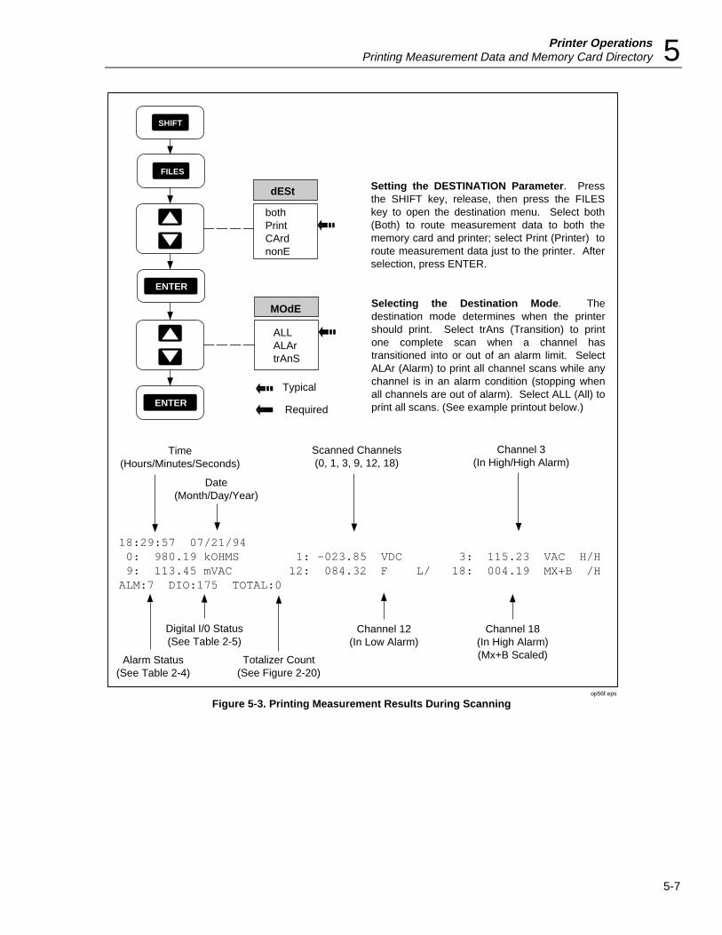
Printer OperationsPrinting Measurement Data and Memory Card Directory 5
5-7
MOdE
ALLALArtrAnS
Selecting the Destination Mode. The destination mode determines when the printer should print. Select trAns (Transition) to print one complete scan when a channel has transitioned into or out of an alarm limit. Select ALAr (Alarm) to print all channel scans while any channel is in an alarm condition (stopping when all channels are out of alarm). Select ALL (All) to print all scans. (See example printout below.)
dESt
bothPrintCArdnonE
SHIFT
FILES
ENTER
Setting the DESTINATION Parameter. Press the SHIFT key, release, then press the FILES key to open the destination menu. Select both (Both) to route measurement data to both the memory card and printer; select Print (Printer) to route measurement data just to the printer. After selection, press ENTER.
Typical
RequiredENTER
18:29:57 07/21/94 0: 980.19 kOHMS 1: -023.85 VDC 3: 115.23 VAC H/H 9: 113.45 mVAC 12: 084.32 F L/ 18: 004.19 MX+B /HALM:7 DIO:175 TOTAL:0
Time(Hours/Minutes/Seconds)
Alarm Status(See Table 2-4)
Date(Month/Day/Year)
Scanned Channels(0, 1, 3, 9, 12, 18)
Digital I/0 Status(See Table 2-5)
Totalizer Count(See Figure 2-20)
Channel 12(In Low Alarm)
Channel 18(In High Alarm)(Mx+B Scaled)
Channel 3(In High/High Alarm)
op56f.eps
Figure 5-3. Printing Measurement Results During Scanning
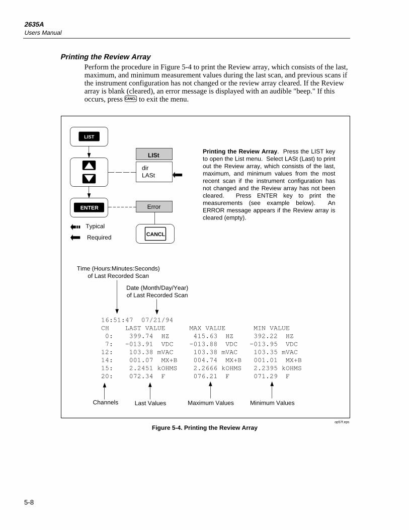
2635AUsers Manual
5-8
Printing the Review ArrayPerform the procedure in Figure 5-4 to print the Review array, which consists of the last,maximum, and minimum measurement values during the last scan, and previous scans ifthe instrument configuration has not changed or the review array cleared. If the Reviewarray is blank (cleared), an error message is displayed with an audible "beep." If thisoccurs, press C to exit the menu.
LIST
ENTER
dirLASt
LISt
Typical
Required
Printing the Review Array. Press the LIST key to open the List menu. Select LASt (Last) to print out the Review array, which consists of the last, maximum, and minimum values from the most recent scan if the instrument configuration has not changed and the Review array has not been cleared. Press ENTER key to print the measurements (see example below). An ERROR message appears if the Review array is cleared (empty).
Date (Month/Day/Year)of Last Recorded Scan
Channels
Time (Hours:Minutes:Seconds)of Last Recorded Scan
Last Values
Error
CANCL
16:51:47 07/21/94CH LAST VALUE MAX VALUE MIN VALUE 0: 399.74 HZ 415.63 HZ 392.22 HZ 7: -013.91 VDC -013.88 VDC -013.95 VDC12: 103.38 mVAC 103.38 mVAC 103.35 mVAC14: 001.07 MX+B 004.74 MX+B 001.01 MX+B15: 2.2451 kOHMS 2.2666 kOHMS 2.2395 kOHMS20: 072.34 F 076.21 F 071.29 F
Maximum Values Minimum Values
op57f.eps
Figure 5-4. Printing the Review Array

Printer OperationsPrinting Measurement Data and Memory Card Directory 5
5-9
Printing the Directory of the Memory CardPerform the procedure in Figure 5-5 to print the directory of the memory card files. Theformat is similar to a PC directory for a disk drive and will print any files that exist onthe memory card.
LIST
ENTER
dirLASt
LISt
Typical
Required
Printing the Memory Card Directory. Press the LIST key to open the List menu; dir (Directory) is selected to print out a directory of all the files on the memory card. Press ENTER to print the directory (example below). If an Err 1 CArd message appears, this usually indicates a card is not inserted or the card is unformatted (see Table 3-1).
SET00.HYD 730 07-21-1994 08:23SET01.HYD 730 07-21-1994 11:16SET02.HYD 730 07-21-1994 16:53DAT00.HYD 1460 07-21-1994 08:43DAT01.HYD 1042 07-21-1994 12:48DAT02.HYD 1250 07-21-1994 17:04 6 FILE(S) 6650 BYTES 18586 BYTES FREE
File Names Date (Month/Day/Year) File Created
Total Numberof Files
Bytes Used and BytesFree (Available)
Time (Hours:Minutes) File Created
Size ofFile in Bytes
op58f.eps
Figure 5-5. Printing the Memory Card Directory

2635AUsers Manual
5-10

6-1
Chapter 6Modem Operations
Title Page
Summary of Modem Operations ....................................................................... 6-3Connecting the Modem to a PC for Modem Configuration .............................. 6-4Configuring the Instrument Modem for Modem Operations ............................ 6-4Connecting the Modem to an Instrument .......................................................... 6-6Configuring the Instrument for Modem Operations.......................................... 6-7Testing the RS-232/Modem Interface ............................................................... 6-8
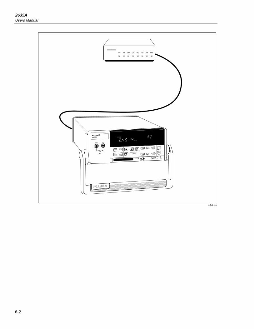
2635AUsers Manual
6-2
FUNC ALRM
Mx+B CANCEL ENTER
RATE
INTVL FILES REVIEW
SHIFT LIST TOTAL
SINGLE
TRIGS
SCAN
MON
CLOCK MODE CLEAR
LOCAL COMM ZERO
mAmVDCAC
k Hz
REVIEWLASTHYDRA
300VMAX
COM V
M
CH
BUSY BATT
HS AA CD OH RD TD TR MR
op84f.eps

Modem OperationsSummary of Modem Operations 6
6-3
Summary of Modem OperationsModem operations allow an RS-232 connection between an instrument and a PC viamodems and telephone lines, instead of a direct RS-232 connection as described inChapter 4, "Computer Operations." Due to the wide variety of modems available andtheir corresponding software, only the most common connection using a Hayes-compatible modem using the AT command set is described. This connection can beadapted to any configuration, following the basic rules in each procedure. A typicaloverall connection diagram is shown in Figure 6-1.
Hayes-compatible modems are both configured and controlled by commands from a PC.Since the Data Bucket does not have the capability to configure a modem, the modem isconfigured using a PC, then the PC is removed and the modem is connected to the DataBucket. The modem operates in a simple answer mode since calls are never originatedfrom the instrument. The modem configuration is stored in the modem memory. Somemodems use an internal battery to prevent the erasure of the configuration if the modempower switch is turned off, while others lose all configuration when the power is turnedoff. Check the manual for your modem for an understanding of how the configuration ismaintained.
The information in this chapter is provided in five parts:
• Connecting the Modem to a PC for Configuration
• Configuring the Modem for Modem Operations
• Connecting the Modem to an Instrument
• Configuring the Instrument for Modem Operations
• Testing the RS-232/Modem Interface
MODEM
HS AA CD OH RD TD TR MR HS AA CD OH RD TD TR MR
HYDRA DATA BUCKET
300VMAX
COM V
FUNC ALRM
Mx+B CANCEL ENTER
RATE
INTVL FILES REVIEW
SHIFT LIST TOTAL
SINGLE
TRIGS
SCAN
MON
CLOCK MODE CLEAR
LOCAL COMM ZERO
mAmVDCAC
k Hz
REVIEWLAST
CH
BUSY BATT
TELEPHONE LINES
RS-232 RS-232
PC
HYDRA
MODEM
op59f.eps
Figure 6-1. Overall PC-to-Instrument Modem Connection

2635AUsers Manual
6-4
Connecting the Modem to a PC for Modem ConfigurationThe two most common configurations for connecting the modem to a PC are shown inFigure 6-2. The modem RS-232 port (DB-25 connector) is cabled to a PC serial COMport that uses either a DB-9 connector or DB-25 connector. The connecting cable can befabricated (See Appendix D) or ordered from Fluke as an option (see Chapter 1).
Configuring the Instrument Modem for Modem OperationsCommands to configure the modem are sent from the PC that is runningcommunications software. The example below uses the Terminal mode that is availableon any PC that is running Windows software. Modem operation at 2400 baud is assumedfor this procedure, which should be adapted, as required.
1. Start Windows and open TERMINAL on the ACCESSORIES menu.
2. Open the SETTINGS menu and select COMMUNICATIONS.
3. In COMMUNICATIONS, select the following, then use OK to exit to TERMINAL:
Connector COM 1 [Typical]
Baud Rate 2400
Data Bits 8
Stop Bits 1
ParityNone
Flow Control None
4. In TERMINAL, enter a few AT <ENTER> character sequences. If the cableconnection is correct and the modem has LED indicators, the data send and datareceive indicator will blink. If LED blinking is not observed, check the cabling andverify that the correct PC COM port was selected in step 3.
5. Enter the command ATV1 <ENTER>, which gives result codes in English, insteadof numbers. For example, the AT <ENTER> characters entered in the last stepwould display the result code OK.
6. Enter the command ATS0=1 <ENTER>, which configures the modem to answercalls after one ring. [The 0 character of the S0 portion of the command is the numberzero.]Observe the result code OK.
7. This completes the software configuration of the modem. Check all modem DIPswitches for proper settings. In particular, some modems have a NO ANSWERswitch that must be disabled or the modem will not answer calls. Be sure the modemremains powered or the configuration data could be lost. Refer to your modemmanual, as required.

Modem OperationsConfiguring the Instrument Modem for Modem Operations 6
6-5
RS-232(DB-9)(MALE)
FLUKE RS41 CABLE(OR EQUAL)
MODEM CONNECTIONWITH PC DB-9CONNECTOR
RS-232 PORT(DB-25)
(FEMALE )
MODEM
HS AA CD OH RD TD TR MR
FLUKE RS41 CABLE(OR EQUAL)
MODEM CONNECTIONWITH PC DB-25CONNECTOR
RS-232 PORT(DB-25)
(FEMALE )
MODEM
HS AA CD OH RD TD TR MR
RS-232 PORT(DB-25)(MALE )
DB-25 TO DB-9ADAPTER
op60f.eps
Figure 6-2. Connecting the Modem to a PC

2635AUsers Manual
6-6
Connecting the Modem to an InstrumentRemove the cable from the PC and connect to the Data Bucket, as shown in Figure 6-3.If a different cable is used, be sure it is a modem cable.
RS-232(DB-9)(MALE)
RS-232 PORT(DB-25)
(FEMALE )
HYDRAMODEM
HS AA CD OH RD TD TR MRHS AA CD OH RD TD TR MR
FLUKE RS41 CABLE(OR EQUAL)
op61f.eps
Figure 6-3. Connecting the Modem to an Instrument

Modem OperationsConfiguring the Instrument for Modem Operations 6
6-7
Configuring the Instrument for Modem OperationsCorrect operation of the instrument RS-232/modem link depends on the baud rate,parity, CTS (Clear To Send), and Echo of the link parameters Perform the procedure inFigure 6-4 to establish the communication link parameters.
SHIFT
LIST38400192009600480024001200600300
bAUd
ENTER
ENTER
PAR
noEOdd
ENTER
Echo
OnOFF
CtS
OnOFF
ENTER
Typical
Required
Selecting the bAUd (Baud) Rate. Press the SHIFT key, release, and then press the LIST key to open the communications parameters menu. The baud rate sets the rate of data transfer between the instrument and the modem. Normally, the highest compatible rate is selected. Select the rate using the up/down arrow keys then press ENTER.
Selecting PAR (Parity). The 8th bit of a character can be set to make all characters odd (Odd) or even (E), or no parity at all (no). The PC checks parity (if selected) and indicates when an error is detected. Select the parity then press ENTER.
Selecting CtS (Clear To Send). The RS-232 CTS line is used to control data flow between the instrument and modem. For most modem applications, CTS is turned On. Make selection then press ENTER.
Selecting Echo. For this RS-232 application, Echo OFF is selected. When modem operations are initiated, any characters sent from the instrument to the modem before the modem has experienced "carrier detect" will cause the modem to suddenly disconnect from the line.
op62f.eps
Figure 6-4. Configuring the Instrument RS-232 Port for Modem Operations

2635AUsers Manual
6-8
Testing the RS-232/Modem InterfaceThe PC end of the modem link involves a similar procedure of connecting the correctcable between the PC and modem, and configuring the modem to support thecommunications link. This is the responsibility of the user due to the variety of availablemodems and software. Be sure the PC COM port has the same parameters as thoseselected in Figure 6-4.
When all connections and configurations are complete, the PC should initiatecommunications with the modem supporting the instrument using the selectedcommunications software. Typically, this means selecting a dial feature, or entering anAT command, e.g., ATDT 123-4567 from the terminal emulation screen. After theconnection is made and the terminal emulation screen is present, enter a few <ENTER>characters to clear the instrument buffer, and note the instrument => prompts on thescreen. Then enter the command *IDN? <ENTER> (since ECHO OFF was selected inFigure 6-4, the *IDN? characters will not appear on screen). The return should beFLUKE,2635A,0,Mn.n An.n Dn.n Ln.n where n.n is replaced with the versions of thedisplayed parameters. (See the *IDN? command in Chapter 4 for more information.)TheRS-232/modem link is operating correctly and the PC may now operate using Starter orLogger applications software, or custom software.
Problems?If the modem does not operate after making the RS-232 connection, telephone lineconnections, and setting the instrument and PC parameters, check the following:
1. No operation of any kind usually indicates a cabling problem, hardwareincompatibility, a modem DIP switch problem, or incorrectly selecting ECHO ON inFigure 6-4 (ECHO OFF must be selected).
2. Incorrect operation usually indicates a configuration incompatibility, i.e., theinstrument and PC baud rate and parity don’t match.
3. Verify the modem configuration data hasn’t been lost or corrupted. Some modemsuse an internal battery to retain configuration data when power is removed, and somemodems lose configuration data if power is removed. If the configuration data issuspect, repeat the configuration procedures in this chapter.

7-1
Chapter 7Maintenance
Title Page
Introduction ....................................................................................................... 7-3Cleaning............................................................................................................. 7-3Line Fuse ........................................................................................................... 7-3Selftest Diagnostics and Error Codes................................................................ 7-4Performance Tests ............................................................................................. 7-4
Accuracy Verification Test ........................................................................... 7-7Channel Integrity Test................................................................................... 7-8Thermocouple Measurement Range Accuracy Test ..................................... 7-9Four-Terminal Resistance Test ..................................................................... 7-10Thermocouple Temperature Accuracy Test.................................................. 7-10Open Thermocouple Response Test ............................................................. 7-11RTD Temperature Accuracy Test ................................................................. 7-13
RTD Temperature Accuracy Test (Using Decade Resistance Source) .... 7-13RTD Temperature Accuracy Test (Using DIN/IEC 751 RTD)................ 7-14
Digital Input/Output Verification Tests ........................................................ 7-15Digital Output Test ................................................................................... 7-15Digital Input Test ...................................................................................... 7-16Totalizer Test ............................................................................................ 7-17Totalizer Sensitivity Test.......................................................................... 7-18
Dedicated Alarm Output Test ....................................................................... 7-18External Trigger Input Test........................................................................... 7-21
Calibration ......................................................................................................... 7-21Variations in the Display................................................................................... 7-22Service ............................................................................................................... 7-22

2635AUsers Manual
7-2
FUNC ALRM
Mx+B CANCEL ENTER
RATE
INTVL FILES REVIEW
SHIFT LIST TOTAL
SINGLE
TRIGS
SCAN
MON
CLOCK MODE CLEAR
LOCAL COMM ZERO
mAmVDCAC
k Hz
REVIEWLASTHYDRA DATA BUCKET
300VMAX
COM V
M
CH
BUSY BATT
5790A AC MEASUREMENTSTANDARD
CALIBRATOR
op85f.eps

MaintenanceIntroduction 7
7-3
IntroductionThis chapter describes basic maintenance that the instrument user can perform. Do notattempt any maintenance not described in this chapter. For additional maintenance,service, and calibration procedures, qualified service personnel can refer to the HydraSeries II Service Manual (part number 688868).
CleaningWWarning
Keep the instrument dry to avoid electrical shock to personnelor damage to the instrument. To prevent damage, never applysolvents to the instrument housing.
For cleaning, wipe the instrument with a cloth that is lightly dampened with water ormild detergent. Do not use aromatic hydrocarbons, chlorinated solvents, or methanol-based fluids.
Line FuseThe instrument uses a type "T" 125 mA, 250V (Slow blow) line fuse in series with thepower supply. To replace this fuse (located on the rear panel), unplug the line cord andremove the fuse holder with the fuse as shown in Figure 7-1. The instrument is shippedwith a replacement fuse secured in the fuse holder.
Power-Line Cord Connector
Line Fuse(T 125 mA, 250V,
Slow Blow)
Fuse Holder(Spare Fuse Provided)
Complies with the limit for a class B computing device
pursuant to Subpart J of Part 15 of FCC Rules
+–
01
23
TR
01
23
45
67
Σ
9-16 VDC PWR
!
+30V
DIGITAL I/O
MEETS 0871 B
To Remove,Squeeze and
Slide Out
op63f.eps
Figure 7-1. Replacing the Line Fuse

2635AUsers Manual
7-4
Selftest Diagnostics and Error CodesWhen the instrument is powered up, the entire display lights.
NoteTo hold the display fully lit, press and hold the K key, then press RON and wait a moment for the instrument to beep. Then release K. Theentire display will now stay on until you press any button; the power-upsequence then resumes.
Selftest diagnostics are performed each time the instrument is powered up. Any errorsencountered during this initial 4-second period are displayed momentarily. Even in thepresence of an error, the instrument still attempts to complete the selftest routine andbegin normal operation.
An error indicates that a malfunction has occurred and maintenance is required. If youencounter an error, note the number or letter and consult Table 7-1. See if the instrumentrepeats the error. If the problem persists and you intend to repair the instrument yourself,refer to the Service Manual. Otherwise, package the instrument securely (using theoriginal container if available.) Then forward the package, postage paid, to the nearestFluke/Philips Service Center. Include a description of the problem. Fluke assumes noresponsibility for damage in transit.
Performance TestsWhen received, the 2635A Hydra Series II is calibrated and in operating condition. Thefollowing Performance Verification Procedures are provided for acceptance testing uponinitial receipt or to verify correct instrument operation. All tests may be performed insequence to verify overall operation, or the tests may be run independently.
If the instrument fails a performance test, calibration adjustment and/or repair is needed.To perform these tests, you will need a Fluke 5700A Multifunction Calibrator orequipment meeting the minimum specifications given in Table 7-2.
Table 7-1. Power-Up Error Codes
Error Description
1 Boot ROM checksum error
2 Instrument ROM checksum error
3 Internal RAM test failed
4 Display power-up test failure
5 Display not responding
6 Instrument configuration corrupted
7 instrument calibration data corrupted
8 Instrument not calibrated
9 A/D converter not responding
A A/D converter ROM test failure
b A/D converter RAM test failure
C A/D converter selftest failed
d Memory Card interface not installed

MaintenancePerformance Tests 7
7-5
Each of the measurements listed in the following steps assume the instrument is beingtested after a 1/2 hour warmup, in an environment with an ambient temperature of 18 to28ºC, and a relative humidity of less than 70%.
NoteAll measurements listed in the performance test tables are made in the slowreading rate unless otherwise noted.
W WarningThe 2635A instrument contains high voltages that can bedangerous or fatal. Only qualified personnel should attempt toservice the instrument.

2635AUsers Manual
7-6
Table 7-2. Recommended Test Equipment
Instrument Type Minimum Specification RecommendedModel
Multifunction Calibrator DC Voltage: Fluke 5700A
Range: 90 mV to 300V dcAccuracy: .005%
AC Voltage:
Frequency Voltage Accuracy
1 kHz 29 mV to 300V 0.05%
100 kHz 15 mV to 300V 1.25%
Frequency:
10 kHz 1V rms .0125%
Decade ResistanceSource Ohms Accuracy
General ResistanceInc. Model RDS 66A
290Ω 0.0125%
2.9 kΩ 0.0125%
29 kΩ 0.0125%
290 kΩ 0.0125%
2.9 MΩ 0.0125%
Note
The 5700A Calibrator provides 0.05% accuracy(rated) on the 3.0 kΩ, 30 kΩ, 300 ke and 3.0MΩ ranges. The 5700A can be used for 0.06%accuracy on the 300Ω range.
Mercury Thermometer 0.02 degrees Celsius resolution Princo ASTM-56C
Thermocouple Probe Type T Fluke P-20T
Room TemperatureOil/Water Bath
Thermos bottle and cap
Multimeter Measures +5V dc Fluke 77
Signal Generator Sinewave, 0.5 to 1V rms 10 Hz to 5 kHz Fluke 6011A
Alternate Equipment List
(Minimum specifications are the same as in the Standard Equipment List)
Instrument Type Recommended Model
DC Voltage Calibrator Fluke 5700A
DMM Calibrator Fluke 5100B (for AC Volts only)
Function/Signal Generator Philips PM5193 or Fluke 6011A
Decade Resistance Source Gen Rad 1433H

MaintenancePerformance Tests 7
7-7
Accuracy Verification Test1. Power up the instrument and allow the temperature to stabilize for 30 minutes.
2. Connect a cable from the Output VA HI and LO connectors of the 5700A to the VΩand COM connectors on the front panel of the Hydra Series II. Select the channel 0function and range on the Hydra Series II and the input level from the 5700A usingthe values listed in Table 7-3. Press the M (monitor) button to measure and displaythe measurement value for channel 0. The display should read between the minimumand maximum values listed in the table.
Table 7-3. Performance Tests (Voltage, Resistance, and Frequency)
FUNCTION RANGE INPUT LEVEL FREQUENCYDISPLAY ACCURACY
(1 Year, 18-28°C)
MIN MAX
DC Volts 90 mV90 mV
300 mV
short (0)90 mV
0V
------
-0.00689.972-0.02
0.00690.028
0.02300 mV 150 mV -- 149.94 150.06300 mV 290 mV -- 289.91 290.09
3V 2.9V -- 2.8991 2.9009-3V -2.9V -- -2.9009 -2.899130V 29V - 28.991 29.009
150V 150V -- 149.94 150.06300V 290V -- 289.91 290.09
NOTEVoltages greater than 150V can only be applied to channels 0,1, and 11.
AC Volts 300 mV 20 mV 1 kHz 19.71 20.29300 mV 20 mV 100 kHz 18.50 21.50300 mV 290 mV 1 kHz 289.28 290.72
3V 290 mV 100 kHz 275.00 305.003V 2.9V 1 kHz 2.8937 2.9063
30V 29V 1 kHz 28.931 29.069150V 150V 1 kHz 149.54 150.46300V 290V 1 kHz 289.34 290.66
NOTEVoltages greater than 150V can only be applied to channels 0, 1, and 11. The rear Input Module mustbe installed when measuring ac volts on channel 0.
NOTEFor 2-terminal measurements, the resistance accuracy given in this table applies to Channel 0 andmakes allowance for up to 0.05 ohm of lead wire resistance. You must add any additional lead wireresistance present in your set up to the resistance values given in this table.
Resistance Using inputs in decades of 3:
300 e short 0.00 0.09300e 299.90 300.15
3 ke short 0.0000 0.00033 ke 2.9989 3.0011
30 ke 30 ke 29.990 30.010300 ke 300 ke 299.88 300.123 Me 3 Me 2.9979 3.0021
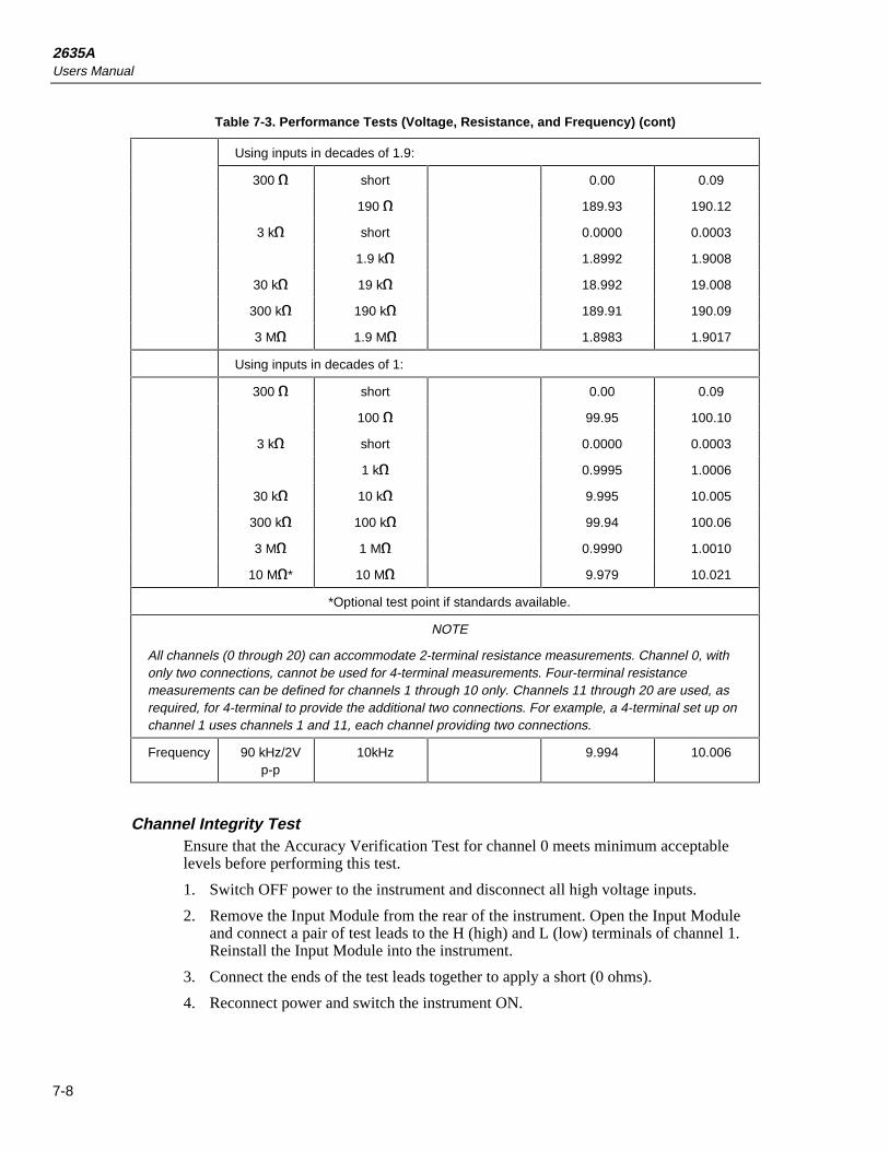
2635AUsers Manual
7-8
Table 7-3. Performance Tests (Voltage, Resistance, and Frequency) (cont)
Using inputs in decades of 1.9:
300 e short 0.00 0.09
190 e 189.93 190.12
3 ke short 0.0000 0.0003
1.9 ke 1.8992 1.9008
30 ke 19 ke 18.992 19.008
300 ke 190 ke 189.91 190.09
3 Me 1.9 Me 1.8983 1.9017
Using inputs in decades of 1:
300 e short 0.00 0.09
100 e 99.95 100.10
3 ke short 0.0000 0.0003
1 ke 0.9995 1.0006
30 ke 10 ke 9.995 10.005
300 ke 100 ke 99.94 100.06
3 Me 1 Me 0.9990 1.0010
10 Me* 10 Me 9.979 10.021
*Optional test point if standards available.
NOTE
All channels (0 through 20) can accommodate 2-terminal resistance measurements. Channel 0, withonly two connections, cannot be used for 4-terminal measurements. Four-terminal resistancemeasurements can be defined for channels 1 through 10 only. Channels 11 through 20 are used, asrequired, for 4-terminal to provide the additional two connections. For example, a 4-terminal set up onchannel 1 uses channels 1 and 11, each channel providing two connections.
Frequency 90 kHz/2Vp-p
10kHz 9.994 10.006
Channel Integrity TestEnsure that the Accuracy Verification Test for channel 0 meets minimum acceptablelevels before performing this test.
1. Switch OFF power to the instrument and disconnect all high voltage inputs.
2. Remove the Input Module from the rear of the instrument. Open the Input Moduleand connect a pair of test leads to the H (high) and L (low) terminals of channel 1.Reinstall the Input Module into the instrument.
3. Connect the ends of the test leads together to apply a short (0 ohms).
4. Reconnect power and switch the instrument ON.

MaintenancePerformance Tests 7
7-9
5. For channel 1, select the two-terminal ohms function and 300 ohms range on theHydra Series II. Press M and ensure the display reads a resistance of less than orequal to 4.0 ohms. (This test assumes that lead wire resistances are less than 0.1Ω.)
6. Open the ends of the test leads and ensure that the display reads OL" (overload).
7. Press M.This will stop the measurement.
8. Connect a cable from the Output VA HI and LO of the 5700A to the Input Moduletest leads (observe proper polarity).
9. Select the VDC function and 300 volt range on the Hydra Series II and first apply0V dc then 290V dc input from the 5700A. Ensure the display reads between theminimum and maximum values as shown in Table 7-3 for the 0 and 290V dc inputlevels.
NoteChannels 0, 1, and 11 have a maximum input of 300V dc or ac (rms). Themaximum input for all other channels is 150V dc or ac (rms).
10. With the exception of the selected voltage range and input voltage from the 5700A,repeat steps 1 through 9 for each remaining Input Module channel (2 through 20).Channels 2 through 10 and 12 through 20 should be configured for the 150V dcrange and an input voltage of 150 volts.
Thermocouple Measurement Range Accuracy TestEnsure that the Accuracy Verification Test for channel 0 meets minimum acceptablelevels before performing this test.
Thermocouple temperature measurements are accomplished using Hydra Series II’s 90mV and internal 900 mV dc ranges. (The 900 mV range is not configurable from theinstrument front panel.) This procedure will provide the means to test these ranges.
Testing the 900 mV dc range requires computer interfacing with a host (terminal orcomputer). The host must send commands to select this range. This range cannot beselected from the Hydra Series II front panel.
1. Ensure that communication parameters ( i.e., transmission mode, baud rate, parity,CTS, and echo mode) on the Hydra Series II and the host are properly configured tosend and receive serial data. Refer to Chapter 4 "Computer Operations."
2. Power up Hydra Series II and allow the temperature to stabilize for 30 minutes.
3. Connect a cable from the Output VA HI and LO connectors of the 5700A to the VΩand COM connectors on the front panel of the Hydra Series II.
4. Set the 5700A to output 0V dc.
5. Using either a terminal or a computer running a terminal emulation program as theselected host, send the following commands to Hydra Series II:
FUNC 0,VDC,5 <CR>
MON 1,0 <CR>
MON_VAL? <CR>
The returned value for channel 0 should be 0 mV ±0.006 mV.
Set the 5700A to output 90 mV DC. Send the following command:
MON_VAL? <CR>

2635AUsers Manual
7-10
The value returned should now be 90 mV ±0.028 mV (between 89.97 and90.028 mV).
6. Change Hydra Series II's channel 0 function to the internal 900 mV dc range byredefining channel 0. Send the following commands:
MON 0 <CR>
FUNC 0,VDC,6 <CR>
Set the 5700A to output 0.9V dc. Send the following commands:
MON 1,0 <CR>
MON_VAL? <CR>
The value returned should be 900 mV ±0.21 mV (899.79 to 900.21mV.)
Four-Terminal Resistance TestEnsure that Channel 0's Accuracy Verification Test for DC Volts and Resistance meetsminimum acceptable levels.
1. Switch OFF power to the instrument and disconnect all high voltage inputs.
2. Remove the Input Module from the rear of the instrument. Open the Input Moduleand connect a pair of test leads (keep as short as possible) to the H (high) and L(low) terminals of channel 1, and connect a second pair of test leads to the H and Lterminals of channel 11. Reinstall the Input Module into the instrument.
3. Observing polarity connect channel 1's test leads to the Sense HI and LO terminalsof the 5700A, and connect channel 11's test leads to the Output HI and LO terminalsof the 5700A. Connect as shown in Figure 7-2.
4. Switch the instrument ON.
5. Select the Four-terminal OHMS function, AUTO range, for channel 1 on the HydraSeries II.
6. Set the 5700A to output the resistance values listed in Table 7-3 (Use decades of1.9).
7. On Hydra Series II press M and ensure the display reads between the minimumand maximum values shown on Table 7-3.
8. The Four-terminal Resistance Test is complete. However, if you desire to performthis test on Input Module channels (2 through 10), repeat steps 1 through 7,substituting the appropriate channel number.
NoteFour-Terminal connections are made using pairs of channels. Four-terminal measurements can be made only on channels 1 though 10 (n). Theaccompanying pairs are channels 11 through 20 (n+10).
Thermocouple Temperature Accuracy TestEnsure that the Thermocouple Measurement Range Accuracy Test meets minimumacceptable levels before performing this test.
1. Switch OFF power to the instrument and disconnect all high voltage inputs.
2. Remove the Input Module from the rear of the instrument. Open the Input Moduleand connect a T-type thermocouple to the H (blue lead) and L (red lead) terminals ofchannel 1. Reinstall the Input Module into the instrument.

MaintenancePerformance Tests 7
7-11
NoteIf other than a T-type thermocouple is used, be sure that the instrument isset up for the type of thermocouple used.
3. Reconnect power and switch the instrument ON.
4. Insert the thermocouple and a mercury thermometer in a room temperature bath.Allow 20 minutes for thermal stabilization.
5. Select the temperature and T-type thermocouple function for channel 1.Press M.
6. The value displayed should be the temperature of the room temperature bath asmeasured by the mercury thermometer (within tolerances given in Table 7-4, plusany sensor inaccuracies.).
7. The Thermocouple Temperature Accuracy Test is complete. However, if you desireto perform this test on any other Input Module channel (2 through 20), repeat steps 1through 6, substituting the appropriate channel number.
Open Thermocouple Response Test1. Switch OFF power to the instrument and disconnect all high voltage inputs.
2. Remove the Input Module from the rear of the instrument. Open the Input Moduleand connect test leads to the H (high) and L (low) terminals of channel 1. Reinstallthe Input Module into the instrument.
Table 7-4. Performance Tests for Thermocouple Temperature Function (ITS-90)
Thermocouple Type Thermocouple Accuracy Specifications 1 Year@ 18-28 Degrees C
J ±0.40°C
K ±0.44°C
N ±0.53°C
E ±0.38°C
T ±0.45°C
1. Reconnect power and switch the instrument ON.
2. Connect the test leads from the Input Module to an 820 ohm resistor.
3. Select the temperature and T-type thermocouple function for channel 1.Press M.
4. The value displayed should approximate the ambient temperature.
5. Replace the 820 ohm resistor with a 4 kilohm resistor to simulate a high resistance oropen thermocouple.
6. Verify a reading of "otc".
7. The Open Thermocouple Response Test is complete. However, if you desire toperform this test on any other Input Module channel (2 through 20), repeat steps 1through 8, substituting the appropriate channel number.

2635AUsers Manual
7-12
1211 13 14 15 16 17 18 19 20
21 3 4 5 6 7 8 9 10
SOURCE(4-WIRE)
SENSE(4-WIRE)
H L H L H L H L H L H L H L H L H L H L
H L H L H L H L H L H L H L H L H L H L
HYDRAINPUT
MODULE
HI HI
LO LO
HI
SENSEV
AUXCURRENT
GUARD GROUND
WIDEBAND
5700A
NC
NC
OUTPUTV AΩ Ω
5700AUUT
SENSE
SENSE
SOURCE
SOURCE
EX GRD: OFF
2-WIRECOMPOFFEX SNS
: ON
op64f.eps
Figure 7-2. Four-Terminal Connections to 5700A

MaintenancePerformance Tests 7
7-13
RTD Temperature Accuracy TestThe following two RTD Temperature Accuracy Tests are different in that one test uses aDecade Resistance Source and the other uses an RTD. Only one of the tests need to beperformed to assure operation.
RTD Temperature Accuracy Test (Using Decade Resistance Source)Ensure that Channel 0’s Accuracy Verification Test for DC Volts and 300 OhmResistance Range meets minimum acceptable levels.
1. Switch OFF power to the instrument and disconnect all high voltage inputs.
2. Remove the Input Module from the rear of the instrument. Open the Input Moduleand connect a pair of test leads (keep as short as possible) to the H (high) and L(low) terminals of channel 1. For Four-terminal performance testing, connect asecond pair of test leads to the H (high) and L (low) terminals of channel 11.Reinstall the Input Module into the instrument.
3. Connect channel 1’s test leads to the Output HI and LO terminals of the DecadeResistance Source. For Four-terminal performance testing, also connect channel 11’stest leads to the Output HI and LO terminals of the Decade Resistance Source.Connect as shown in Figure 7-3.
NoteFour-terminal connections are made using pairs of channels. Four-terminal measurements can be made only on channels 1 though 10 (n). Theaccompanying pairs are channels 11 through 20 (n+10).
4. Switch the instrument ON.
5. Select the Four-terminal RTD temperature function, RTD type PT, for channel 1 onthe Hydra Series II. Press M, select a Decade Resistance value, and ensure thedisplay reads between the minimum and maximum values shown on Table 7-5.
6. The RTD Temperature Accuracy test is complete. However if you desire to performthis test on Input Module channels (2 through 10), repeat steps 1 through 5,substituting the appropriate channel number.
NoteThe only type of temperature measurement that can be made on channel 0is two-terminal RTD. Channels 11 through 20 will support only two-terminal RTDs.
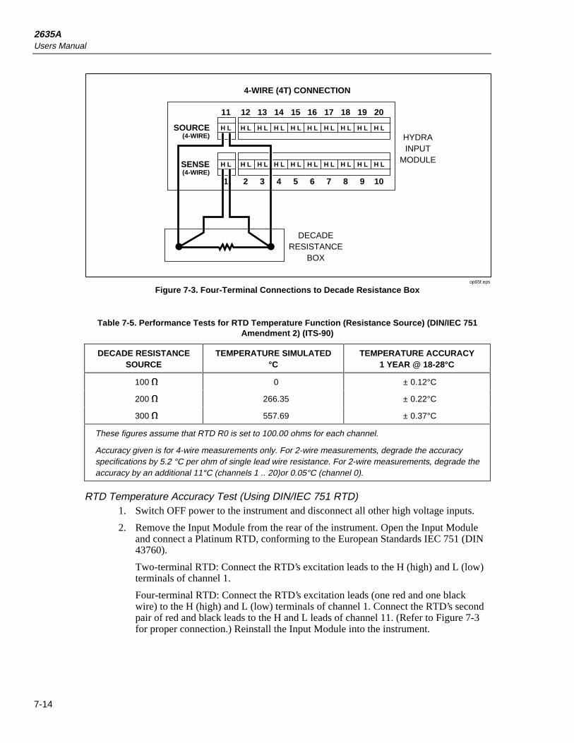
2635AUsers Manual
7-14
1211 13 14 15 16 17 18 19 20
21 3 4 5 6 7 8 9 10
SOURCE(4-WIRE)
SENSE(4-WIRE)
H L H L H L H L H L H L H L H L H L H L
H L H L H L H L H L H L H L H L H L H L
4-WIRE (4T) CONNECTION
DECADERESISTANCE
BOX
HYDRAINPUT
MODULE
op65f.eps
Figure 7-3. Four-Terminal Connections to Decade Resistance Box
Table 7-5. Performance Tests for RTD Temperature Function (Resistance Source) (DIN/IEC 751Amendment 2) (ITS-90)
DECADE RESISTANCESOURCE
TEMPERATURE SIMULATED°C
TEMPERATURE ACCURACY1 YEAR @ 18-28°C
100 e 0 ± 0.12°C
200 e 266.35 ± 0.22°C
300 e 557.69 ± 0.37°C
These figures assume that RTD R0 is set to 100.00 ohms for each channel.
Accuracy given is for 4-wire measurements only. For 2-wire measurements, degrade the accuracyspecifications by 5.2 °C per ohm of single lead wire resistance. For 2-wire measurements, degrade theaccuracy by an additional 11°C (channels 1 .. 20)or 0.05°C (channel 0).
RTD Temperature Accuracy Test (Using DIN/IEC 751 RTD)1. Switch OFF power to the instrument and disconnect all other high voltage inputs.
2. Remove the Input Module from the rear of the instrument. Open the Input Moduleand connect a Platinum RTD, conforming to the European Standards IEC 751 (DIN43760).
Two-terminal RTD: Connect the RTD’s excitation leads to the H (high) and L (low)terminals of channel 1.
Four-terminal RTD: Connect the RTD’s excitation leads (one red and one blackwire) to the H (high) and L (low) terminals of channel 1. Connect the RTD’s secondpair of red and black leads to the H and L leads of channel 11. (Refer to Figure 7-3for proper connection.) Reinstall the Input Module into the instrument.

MaintenancePerformance Tests 7
7-15
NoteFour-terminal connections are made using pairs of channels. Four-terminal measurements can be made only on channels 1 though 10 (n).Their accompanying pairs are channels 11 through 20 (n+10).
3. Switch the instrument ON.
4. Insert the RTD probe and a mercury thermometer in a room temperature bath. Allow20 minutes for thermal stabilization.
5. Dependent on the type of connection made in step 2, select either the two-terminal orfour-terminal RTD temperature function, RTD type PT (DIN/IEC 751), for channel1 on the Hydra Series II. Press M and ensure the display reads the temperature ofthe room temperature bath (within tolerances shown in Table 7-6) as measured bythe mercury thermometer.
6. The RTD Temperature Accuracy test is complete. However if you desire to performthis test on any other channel (0 or 2 through 20) repeat steps 1 through 5substituting the appropriate channel number.
NoteThe only type of temperature measurement that can be made on channel 0is two-terminal RTD. Channels 11 through 20 will support only two-terminal RTDs.
Table 7-6. Performance Tests for RTD Temperature Function (DIN/ IEC 751 Amendment 2)(ITS-90)
RTD TYPE TEMPERATURE ACCURACYSPECIFICATIONS 1 YEAR @ 18-28°C
2-wire (channel 0) -0.54°C to 0.59°C
2-wire (channels 1-20) -0.54°C to 11.54°C
4-wire ±0.54°C
Assumes RTD R0 is set to 100.00 e for each channel.
Digital Input/Output Verification TestsDigital Input/Output verification testing requires computer interfacing with a host(terminal or computer). The host must send commands to the instrument to control thedigital lines for this test. Refer to Chapter 4 for a description of configuring andoperating the instrument.
Digital Output Test1. Ensure that communication parameters ( i.e., transmission mode, baud rate, parity,
CTS, and echo mode) on the Hydra Series II and the host are properly configured tosend and receive serial data. Refer to Chapter 4.
2. Switch OFF power to the instrument and disconnect all high voltage inputs.
3. Remove the Digital I/O ten terminal connector from the rear of the instrument andall external connections to it. Connect short wires (to be used as test leads) to theGROUND and 0 through 7 terminals. Leave the other wire ends unconnected at thistime. Reinstall the connector.
4. Switch power ON to both Hydra Series II and the host. Verify that Hydra Series II isnot scanning. If Hydra Series II is scanning, press Q to turn scanning off, thencycle power off-on again.

2635AUsers Manual
7-16
5. Using a digital multimeter (DMM), verify that all digital outputs (0-7) are in theOFF or HIGH state. This is done by connecting the low or common of themultimeter to the ground test lead and the high of the multimeter to the digital outputand verifying a voltage greater than +3.8V dc.
6. Using either a terminal or a computer running a terminal emulation program, set upHydra Series II to turn Digital Outputs ON (LOW state).
In sequence send the following commands to Hydra Series II and measure that thecorrect Digital Output line transitioned LOW measures less than+0.8V dc.
DO_LEVEL 0,0 <CR>
Ensure that output 0 measures a LOW state.
DO_LEVEL 1,0 <CR>
Ensure that output 1 measures a LOW state.
DO_LEVEL 2,0 <CR>
Ensure that output 2 measures a LOW state.
Repeat the command for all eight outputs.
7. Set up Hydra Series II to turn Digital Outputs OFF (HIGH state).
In sequence send the following commands to Hydra Series II and measure that thecorrect Digital Output line transitioned HIGH measures greater than +3.8V dc.
DO_LEVEL 0,1 <CR>
Ensure that output 0 measures a HIGH state.
DO_LEVEL 1,1 <CR>
Ensure that output 1 measures a HIGH state.
Repeat the command for all eight outputs.
Digital Input Test1. Perform the DIGITAL OUTPUT TEST steps 1 through 5.
2. Using either a terminal or a computer running a terminal emulation program, set upHydra Series II to read the Digital Input lines.
Send the following command to Hydra Series II:
DIO_LEVELS? <CR>
Verify that the returned value is 255.
NoteThe number returned is the decimal equivalent of the Digital Input binaryword (inputs 0 through 7’s status). See Table 7-7 to determine if thenumber returned corresponds to the bits jumpered to ground in this test.
3. Jumper input 0 to ground by connecting the ground test lead to input 0’s test lead.
Then send the following command to Hydra Series II:
DIO_LEVELS? <CR>
Verify that the returned value is 254.
4. Disconnect input 0 from ground then jumper input 1 to ground.
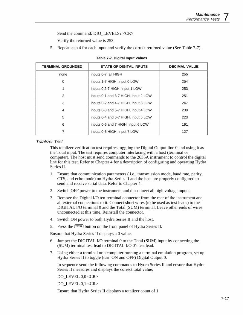
MaintenancePerformance Tests 7
7-17
Send the command: DIO_LEVELS? <CR>
Verify the returned value is 253.
5. Repeat step 4 for each input and verify the correct returned value (See Table 7-7).
Table 7-7. Digital Input Values
TERMINAL GROUNDED STATE OF DIGITAL INPUTS DECIMAL VALUE
none inputs 0-7, all HIGH 255
0 inputs 1-7 HIGH, input 0 LOW 254
1 inputs 0,2-7 HIGH, input 1 LOW 253
2 inputs 0-1 and 3-7 HIGH, input 2 LOW 251
3 inputs 0-2 and 4-7 HIGH, input 3 LOW 247
4 inputs 0-3 and 5-7 HIGH, input 4 LOW 239
5 inputs 0-4 and 6-7 HIGH, input 5 LOW 223
6 inputs 0-5 and 7 HIGH, input 6 LOW 191
7 inputs 0-6 HIGH, input 7 LOW 127
Totalizer TestThis totalizer verification test requires toggling the Digital Output line 0 and using it asthe Total input. The test requires computer interfacing with a host (terminal orcomputer). The host must send commands to the 2635A instrument to control the digitalline for this test. Refer to Chapter 4 for a description of configuring and operating HydraSeries II.
1. Ensure that communication parameters ( i.e., transmission mode, baud rate, parity,CTS, and echo mode) on Hydra Series II and the host are properly configured tosend and receive serial data. Refer to Chapter 4.
2. Switch OFF power to the instrument and disconnect all high voltage inputs.
3. Remove the Digital I/O ten-terminal connector from the rear of the instrument andall external connections to it. Connect short wires (to be used as test leads) to theDIGITAL I/O terminal 0 and the Total (SUM) terminal. Leave other ends of wiresunconnected at this time. Reinstall the connector.
4. Switch ON power to both Hydra Series II and the host.
5. Press the O button on the front panel of Hydra Series II.
Ensure that Hydra Series II displays a 0 value.
6. Jumper the DIGITAL I/O terminal 0 to the Total (SUM) input by connecting the(SUM) terminal test lead to DIGITAL I/O 0’s test lead.
7. Using either a terminal or a computer running a terminal emulation program, set upHydra Series II to toggle (turn ON and OFF) Digital Output 0.
In sequence send the following commands to Hydra Series II and ensure that HydraSeries II measures and displays the correct total value:
DO_LEVEL 0,0 <CR>
DO_LEVEL 0,1 <CR>
Ensure that Hydra Series II displays a totalizer count of 1.
2635AUsers Manual
7-18
8. Again in sequence, send the commands:
DO_LEVEL 0,0 <CR>
DO_LEVEL 0,1 <CR>
Hydra Series II should now display a totalizer count of 2.
9. Repeat step 8 for each incremental totalizing count.
10. Set the Hydra Series II’s totalized count to a value near full range (65535) and testfor overload.
Send the following commands to Hydra Series II:
TOTAL 65534 <CR>
DO_LEVEL 0,0 <CR>
DO_LEVEL 0,1 <CR>
A totalizer count of 65535 should be displayed.
11. Send:
DO_LEVEL 0,0 <CR>
DO_LEVEL 0,1 <CR>
Hydra Series II’s display should now read "OL". This indicates that the counter haschanged from its maximum count (65535) to zero (0) and has set the TotalizeOverflow bit in the Instrument Event Register.
Totalizer Sensitivity Test1. Perform the Totalizer Test and ensure that it is operational.
2. Remove the jumper connecting the (SUM) terminal test lead to output 0’s test lead.
3. Ensure that Hydra Series II is still in the totalize display mode. If not, press the Obutton. Reset the totalizer count shown on the display by pressing Hydra Series II’sfront panel K button followed by O (ZERO) button.
Hydra Series II’s display should now show a value of 0.
4. Connect the output of the signal generator to the SUM and GROUND terminals.
5. Program the signal generator to output a 1.5V rms sine signal at 10 Hz.
Hydra Series II’s display should now show the totalizing value incrementing at a 10count per second rate.
Dedicated Alarm Output TestThe Dedicated Alarm Output Test verifies that Alarm Outputs 0 through 3 arefunctioning properly. Because this test is dependent on voltage readings, the AccuracyVerification Test for channel 0 and the Channel Integrity Test for channels 1 through 3should be performed if voltage readings are suspect.
1. Switch OFF power to the instrument and disconnect all high voltage inputs.
2. Remove the Alarm Output eight-terminal connector module from the rear of HydraSeries II and all external connections to it. Connect short wires (to be used as testleads) to the GROUND and 0 through 3 terminals. Leave other ends of wiresunconnected at this time. Reinstall the connector.

MaintenancePerformance Tests 7
7-19
3. Remove the Input Module from the rear of Hydra Series II. Open the Input Moduleand jumper the H (high) terminal of channels 1, 2, and 3 together. Connect a testlead to the H of channel 1. Also jumper the L (low) terminals of channel 1, 2, and 3together. Connect a second test lead to the L of channel 1. Reinstall the InputModule into Hydra Series II. Refer to Figure 7-4.
4. Switch power ON.
5. Using a digital multimeter (DMM), verify that alarm outputs 0 through 3 are in theOFF or HIGH state. Perform this test by connecting the low or common of themultimeter to the ground test lead and the high of the multimeter to the alarm output.Verify a voltage greater than +3.8V dc.
6. Connect a cable from the Output VA HI and LO connectors of the 5700A to the VΩand COM connectors on the front panel of Hydra Series II. Then jumper HydraSeries II’s VΩ terminal to the H (high) test lead of the Input Module and the COMterminal to the L (low) test lead.
7. On Hydra Series II, select the VDC function, 3V range, and assign a HI alarm limitof +1.0000 for channels 0 through 3. Set up all other channels (4-20) to the OFFfunction. Select a scan interval of 5 seconds.
8. Set the 5700A to output +0.9900 volts.
9. Press Hydra Series II’s Q button. Hydra Series II should scan channels 0 through 3every 5 seconds.
10. Using a digital multimeter, again verify that alarm outputs 0 through 3 are in theOFF or HIGH state.
11. Set the 5700A to output +1.1000 volts. Verify that the alarm outputs 0 through 3 arein the ON or LOW state (measure less than +0.8V dc).
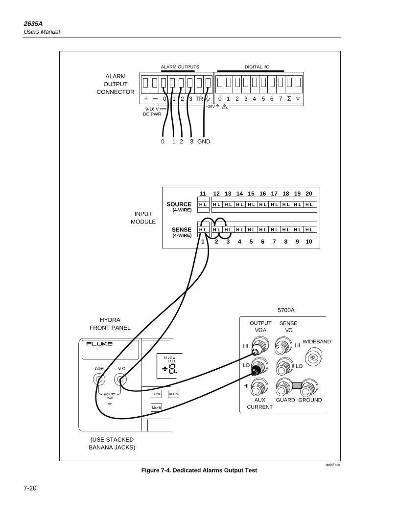
2635AUsers Manual
7-20
1211 13 14 15 16 17 18 19 20
21 3 4 5 6 7 8 9 10
SOURCE(4-WIRE)
SENSE(4-WIRE)
H L H L H L H L H L H L H L H L H L H L
H L H L H L H L H L H L H L H L H L
INPUTMODULE
(USE STACKEDBANANA JACKS)
+ – 0 1 2 3 TR 0 1 2 3 4 5 6 7 Σ9-16 V
DC PWR
!+30V
ALARM OUTPUTS DIGITAL I/O
ALARMOUTPUT
CONNECTOR
V
300VMAX
REVIEWLAST
COM Ω
FUNC ALRM
Mx+B
H L
HYDRAFRONT PANEL
HI HI
LO LO
HI
OUTPUTV A
SENSEV
AUXCURRENT
GUARD GROUND
WIDEBAND
Ω Ω
5700A
+ – 0 1 2 3 TR
GND3210
0 1 2 3 4 5 6 7 Σ
op66f.eps
Figure 7-4. Dedicated Alarms Output Test

MaintenanceCalibration 7
7-21
External Trigger Input TestThe External Trigger Input Test verifies that the rear panel trigger input of Hydra SeriesII is functioning properly.
1. Switch OFF power to the instrument and disconnect all high voltage inputs.
2. Remove the Alarm Output eight terminal connector module from the rear of HydraSeries II and all external connections to it. Connect short wires (to be used as testleads) to the GROUND and TR terminals. Leave other ends of wires unconnected atthis time. Reinstall the connector. Refer to Figure 7-5.
3. Switch power ON.
4. On Hydra Series II, select the VDC function, 30V range for channels 0 through5.Select a scan interval of 30 seconds.
5. Select trigger ON to enable the external trigger input. Press the K and M(TRIGS) buttons (the display shows TRIG), then press either the up or down arrowbuttons to display ON. Press E.
6. Press Hydra Series II’s Q button. Hydra Series II should scan channels 0 through 5once every 30 seconds.
7. During the interval when scanning is not occurring, connect (short) the test leads ofthe TR and ground Alarm Output terminals.
Ensure the connection causes a single scan to occur.
8. Disconnect (open) the TR and ground connection.
Ensure the scan continues to execute at its specified interval.
+ – 0 1 2 3 TR 0 1 2 3 4 5 6 7 Σ9-16 V
DC PWR
!+30V
ALARM OUTPUTS DIGITAL I/O
+ – 0 1 2 3 TR 0 1 2 3 4 5 6 7 Σ
op67f.eps
Figure 7-5. External Trigger Test
CalibrationNote
Refer to the Fluke Hydra Series II Service Manual (P/N 688868) forcalibration procedures. The instrument must be stabilized in anenvironment with an ambient temperature of 22 to 24ºC and a relativehumidity of less than 70% and must have been turned on for at least 30minutes prior to calibration.
The instrument features closed-case calibration controlled over the Computer Interface.Using known reference sources, closed-case calibration has many advantages. There are

2635AUsers Manual
7-22
no parts to disassemble, no mechanical adjustments to make, and the instrument can becalibrated by an automated instrumentation system.
The instrument should normally be calibrated on a regular cycle, typically every 90 daysor 1 year. The chosen calibration cycle depends on the accuracy specification you wishto maintain. The instrument should also be calibrated if it fails the performance test orhas undergone repair.
NoteDo not press CAL ENABLE unless you have a copy of the Service Manualand intend to calibrate the instrument. If you have activated calibrationand wish to exit calibration, press CAL ENABLE until CAL disappearsfrom the display (or press power OFF).
Refer to the Hydra Series II Service Manual for the essential calibration procedures.
Variations in the DisplayUnder normal operation, the display presents various combinations of brightly and dimlylit annunciators and digits. However, you may encounter other, random irregularitiesacross different areas of the display under the following circumstances:
• After prolonged periods of displaying the same information.
• If the display has not been used for a prolonged period.
This phenomenon can be cleared by activating the entire display and leaving it onovernight (or at least for several hours). Use the following procedure to keep the displayfully lit:
1. With power OFF, press and hold K, then press power ON.
2. Wait a moment for the instrument to beep, then release K.The entire display willnow stay on until you are ready to deactivate it.
3. At the end of the activation period, press any button on the front panel; theinstrument resumes the mode in effect prior to the power interruption (Active orInactive).
ServiceIf the instrument fails, check that operating instructions presented earlier in this manualare being followed. If the problem cannot be remedied, forward the instrument, postagepaid, to the nearest Fluke/Philips Service Center. Be sure to pack the instrumentsecurely; use the original container if available. Include a description of the problem.Fluke assumes NO responsibility for damage in transit.
To locate an authorized service center, visit us on the World Wide Web: www.fluke.comor call Fluke using any of the phone numbers listed below.
1-800-44-FLUKE (1-800-443-5853) in U.S.A. and Canada+31 402-678-200 in Europe+81-3-3434-0181 Japan+65-*-276-6196 Singapore+1-425-356-5500 in other countries

Appendices
Appendix Title Page
A Specifications....................................................................................................... A-1B Crosstalk Considerations ..................................................................................... B-1C Binary Upload of Logged Data............................................................................ C-1D RS-232 Cabling.................................................................................................... D-1E 8-Bit Binary-Coded-Decimal Table..................................................................... E-1F Memory Card File Formats.................................................................................. F-1G True RMS Measurements .................................................................................... G-1


A-1
Appendix ASpecifications
IntroductionThe instrument specifications presented here are applicable within the conditions listedin the Environmental chapter.
The specifications state total instrument accuracy following calibration, including:
• A/D errors
• Linearization conformity
• Initial calibration errors
• Isothermality errors
• Relay thermal emf’s
• Reference junction conformity
• Temperature coefficients
• Humidity errors
Sensor inaccuracies are not included in the accuracy figures.
Accuracies at Ambient Temperatures Other than SpecifiedTo determine typical accuracies at temperatures intermediate to those listed in thespecification tables, linearly interpolate between the applicable 0ºC to 60ºC and 18ºC to28ºC accuracy specifications.
Response TimesRefer to Typical Scanning Rate and Maximum Autoranging Time later in this Appendix.
DC Voltage Measurements
ResolutionSee Table A-1

2635AUsers Manual
A-2
Table A-1. DC Voltage Measurements - Resolution
Range Resolution
Slow Fast
90 mV* 1 µV 10 µV
300 mV 10 µV 0.1 mV
3V 0.1 mV 1 mV
30V 1 mV 10 mV
300V 10 mV 0.1 V
900 mV** 10 µV 0.1 mV
* Not used in Autoranging
*** Computer interface only (see FUNC command).
AccuracySee Table A-2.
Table A-2. DC Voltage Measurements - Accuracy
ACCURACY ±(%±V)
RANGE 18°C TO 28°C 0°C TO 60°C
90 DAYSSLOW
1 YEARSLOW
1 YEARFAST
1 YEARSLOW
1 YEARFAST
90 mV* .019% + 6 µV .024% + 6 µV .044% + 20 µV .068% + 6 µV .088% + 20 µV
300 mV .018% + 20 µV .023% + 20 µV .040% + 0.2 mV .067% + 20 µV .084% + 0.2 mV
3V .019% + 0.2 mV .024% + 0.2 mV .041% + 2 mV .065% + 0.2 mV .082% + 2 mV
30V .019% + 2 mV .024% + 2 mV .041% + 20 mV .086% + 2 mV .103% + 20 mV
150/300V .019% + 20 mV .024% + 20 mV .041% + 0.2 V .087% + 20 mV .104% + 0.2 V
900 mV* ** .016% + 20 µV .021% + 20 µV .037% + 0.3 mV .064% + 20 µV .096% + 0.3 mV
* Not used in Autoranging.
** Computer interface only (see FUNC command).
Input Impedance100 Me minimum in parallel with 150 pF maximum for all ranges 3V and below 10 Me
in parallel with 100 pF maximum for the 30V and 300V ranges
Normal Mode Rejection53 dB minimum at 60 Hz ±0.1%, slow rate
47 dB minimum at 50 Hz ±0.1%, slow rate
Common Mode Rejection120 dB minimum at dc, 1 ke imbalance, slow rate120 dB minimum at 50 or 60 Hz ±0.1%, 1 ke imbalance, slow rate

AppendicesSpecifications A
A-3
Maximum Input300V dc or ac rms on any range for channels 0,1, and 11150V dc or ac rms for channels 2 to 10 and 12 to 20Voltage ratings between channels must not be exceeded.
Cross-Talk RejectionRefer to Appendix B.

2635AUsers Manual
A-4
AC Voltage Inputs (True rms AC Voltage, AC-Coupled Inputs)
ResolutionSee Table A-3.
Table A-3. AC Voltage Measurements - Resolution
Range Resolution Minimum Input for RatedSlow Fast Accuracy
300 mV 10 µV 100 µV 20 mV3V 100 µV 1 mV 200 mV
30V 1 mV 10 mV 2V150/300V 10 mV 100 mV 20V
AccuracySee Table A-4.
Table A-4. AC Voltage Measurements - Accuracy
1 Year Accuracy ±(% ± V)
Range Frequency 18°C to 28°C 0°C to 60°C
Slow Fast Slow Fast
20 Hz - 50 Hz 1.43% + 0.25 mV 1.43% + 0.4 mV 1.54% + 0.25 mV 1.54% + 0.4 mV
50 Hz - 100 Hz 0.30% + 0.25 mV 0.30% + 0.4 mV 0.41% + 0.25 mV 0.41% + 0.4 mV
300 mV 100 Hz - 10 kHz 0.16% + 0.25 mV 0.16% + 0.4 mV 0.27% + 0.25 mV 0.27% + 0.4 mV
10 kHz - 20 kHz 0.37% + 0.25 mV 0.37% + 0.4 mV 0.68% + 0.25 mV 0.68% + 0.4 mV
20 kHz - 50 kHz 1.9% + 0.30 mV 1.9% + 0.5 mV 3.0% + 0.30 mV 3.0% + 0.5 mV
50 kHz - 100 kHz 5.0% + 0.50 mV 5.0% + 1.0 mV 7.0% + 0.50 mV 7.0% + 1.0 mV
20 Hz - 50 Hz 1.42% + 2.5 mV 1.42% + 4 mV 1.53% + 2.5 mV 1.53% + 4 mV
50 Hz - 100 Hz 0.29% + 2.5 mV 0.29% + 4 mV 0.40% + 2.5 mV 0.40% + 4 mV
3V 100 Hz - 10 kHz 0.13% + 2.5 mV 0.13% + 4 mV 0.24% + 2.5 mV 0.24% + 4 mV
10 kHz - 20 kHz 0.22% + 2.5 mV 0.22% + 4 mV 0.35% + 2.5 mV 0.35% + 4 mV
20 kHz - 50 kHz 0.6% + 3.0 mV 0.6% + 5 mV 0.9% + 3.0 mV 0.9% + 5 mV
50 kHz - 100 kHz 1.0% + 5.0 mV 1.0% + 10 mV 1.4% + 5.0 mV 1.4% + 10 mV
20 Hz - 50 Hz 1.43% + 25 mV 1.43% + 40 mV 1.58% + 25 mV 1.58% + 40 mV
50 Hz - 100 Hz 0.29% + 25 mV 0.29% + 40 mV 0.45% + 25 mV 0.45% + 40 mV
30V 100 Hz - 10 kHz 0.15% + 25 mV 0.15% + 40 mV 0.30% + 25 mV 0.30% + 40 mV
10 kHz - 20 kHz 0.22% + 25 mV 0.22% + 40 mV 0.40% + 25 mV 0.40% + 40 mV
20 kHz - 50 kHz 0.9% + 30 mV 0.9% + 50 mV 1.1% + 30 mV 1.1% + 50 mV
50 kHz - 100 kHz 2.0% + 50 mV 2.0% + 100 mV 2.2% + 50 mV 2.2% + 100 mV
20 Hz - 50 Hz 1.42% + 0.25V 1.42% + 0.4V 1.57% + 0.25V 1.57% + 0.4V
50 Hz - 100 Hz 0.29% + 0.25V 0.29% + 0.4V 0.44% + 0.25V 0.44% + 0.4V
300V 100 Hz - 10 kHz 0.14% + 0.25V 0.14% + 0.4V 0.29% + 0.25V 0.29% + 0.4V
10 kHz - 20 kHz 0.22% + 0.25V 0.22% + 0.4V 0.38% + 0.25V 0.38% + 0.4V
20 kHz - 50 kHz 0.9% + 0.30V 0.9% + 0.5V 1.0% + 0.30V 1.0% + 0.5V
50 kHz - 100 kHz 2.5% + 0.50V 2.5% + 1.0V 2.6% + 0.50V 2.6% + 1.0V

AppendicesSpecifications A
A-5
Temperature Measurements (Thermocouples)
AccuracySee Table A-5.
Table A-5. Temperature Measurements - Accuracy (Thermocouples) (IPTS-68)
Thermocouple Accuracy (±°C)*
18°C to 28°C 0°C TO 60°C
Type Temperature(C°)
90 DaysSlow
1 YearSlow
1 Year Fast
1 YearSlow
1 Year Fast
-100 to -30 0.42 0.43 0.90 0.54 1.08
J -30 to 150 0.37 0.38 0.80 0.57 1.01
150 to 760 0.44 0.48 0.93 0.88 1.37
-100 to -25 0.51 0.52 1.12 0.64 1.30
K -25 to 120 0.43 0.44 0.94 0.62 1.15
120 to 1000 0.81 0.87 1.57 1.47 2.22
1000 to 1372 1.05 1.15 2.03 2.01 2.95
-100 to -25 0.61 0.62 1.42 0.73 1.60
N -25 to 120 0.53 0.54 1.21 0.68 1.39
120 to 410 0.50 0.52 1.11 0.74 1.31
410 to 1300 1.00 1.08 1.82 1.75 2.53
-100 to -25 0.43 0.44 0.89 0.56 1.08
E -25 to 350 0.38 0.41 0.77 0.64 1.02
350 to 650 0.41 0.45 0.84 0.82 1.24
650 to 1000 0.67 0.73 1.22 1.28 1.81
-150 to 0 0.69 0.71 1.51 0.83 1.72
T 0 to 120 0.45 0.46 0.95 0.59 1.13
120 to 400 0.41 0.43 0.82 0.66 1.06
250 to 400 0.89 0.91 2.53 1.07 2.71
R 400 to 1000 0.93 0.98 2.35 1.37 2.67
1000 to 1767 1.39 1.48 2.98 2.26 3.78
250 to 1000 1.02 1.07 2.69 1.49 2.96
S 1000 to 1400 1.23 1.29 2.75 1.87 3.34
1400 to 1767 1.56 1.65 3.38 2.48 4.24
600 to 1200 1.22 1.23 3.64 1.38 3.81
B 1200 to 1550 1.18 1.23 2.61 1.64 3.03
1550 to 1820 1.42 1.48 2.95 2.02 3.49
0 to 150 0.73 0.75 1.92 0.87 2.10
150 to 650 0.70 0.74 1.66 1.09 2.04
C 650 to 1000 0.90 0.96 2.01 1.49 2.58
1000 to 1800 1.74 1.86 3.48 3.00 4.66
1800 to 2316 2.81 3.03 5.56 5.00 7.60
*Sensor inaccuracies are not included

2635AUsers Manual
A-6
Table A-6. Temperature Measurements - Accuracy (Thermocouples) (ITS-90)
Thermocouple Accuracy (±°C)*
18°C to 28°C 0°C to 60°C
Type
(°C)
Temperature
(°C)
90 Days
Slow
1 Year
Slow
1 Year
Fast
1 Year
Slow
1 Year
Fast
-100 to -30 0.42 0.43 0.91 0.55 1.08
J -30 to 150 0.37 0.39 0.80 0.57 1.02
150 to 760 0.44 0.48 0.94 0.88 1.38
-100 to -25 0.52 0.53 1.13 0.65 1.31
K -25 to 120 0.43 0.44 0.93 0.62 1.16
120 to 1000 0.61 0.68 1.38 1.28 2.03
1000 to 1372 0.89 0.98 1.87 1.85 2.79
-100 to -25 0.62 0.63 1.44 0.75 1.61
N -25 to 120 0.53 0.55 1.22 0.67 1.39
120 to 410 0.47 0.49 1.08 0.69 1.28
410 to 1300 0.70 0.78 1.52 1.45 2.23
-100 to -25 0.44 0.46 0.91 0.57 1.09
E -25 to 350 0.38 0.39 0.77 0.61 0.98
350 to 650 0.39 0.43 0.82 0.80 1.23
650 to 1000 0.50 0.56 1.05 1.11 1.63
-150 to 0 0.68 0.69 1.50 0.82 1.71
T 0 to 120 0.45 0.46 0.95 0.59 1.13
120 to 400 0.36 0.39 0.78 0.61 1.02
250 to 400 0.83 0.85 2.47 1.02 2.66
R 400 to 1000 0.79 0.81 2.30 1.15 2.53
1000 to 1767 0.96 1.05 2.59 1.85 3.42
250 to 1000 0.88 0.89 2.60 1.26 2.80
S 1000 to 1400 0.83 0.89 2.34 1.47 2.94
1400 to 1767 1.07 1.17 2.96 2.03 3.84
600 to 1200 1.11 1.12 3.53 1.27 3.69
B 1200 to 1550 0.74 0.77 2.25 1.18 2.57
1550 to 1820 0.82 0.89 2.35 1.43 2.90
0 to 150 0.72 0.73 1.90 0.86 2.08
150 to 650 0.62 0.64 1.62 0.99 1.94
C 650 to 1000 0.70 0.76 1.81 1.29 2.38
1000 to 1800 1.12 1.25 2.86 2.38 4.04
1800 to 2316 1.86 2.08 4.61 4.06 6.66
* Sensor inaccuracies are not included.

AppendicesSpecifications A
A-7
Input Impedance100 MΩ minimum in parallel with 150 pF maximum
Common Mode and Normal Mode RejectionSee the specifications for dc voltage measurements.
Cross-Talk RejectionRefer to Appendix B.
Open Thermocouple DetectSmall ac signal injection and detection scheme before each measurement detects greaterthan 1 to 4 kΩ as open. Performed on each channel unless defeated by computercommand
Temperature Measurements (RTDs)
AccuracySee Table A-7, A-8 and A-9.
Table A-7. Temperature Measurements - Accuracy (RTDs) (IEC751 Amendment 2) (ITS-90)
RTD 4-Wire Accuracy* (±°C)
Temperature Resolution 18°C to 28°C 0°C to 60°C
(°C) Slow Fast 90 DaySlow
1 YearSlow
1 YearFast
1 YearSlow
1 YearFast
-200.00 0.02 0.1 0.05 0.05 0.47 0.06 0.48
0.00 0.02 0.1 0.08 0.09 0.55 0.13 0.59
100.00 0.02 0.1 0.10 0.10 0.58 0.17 0.64
300.00 0.02 0.1 0.13 0.14 0.65 0.24 0.75
600.00 0.02 0.1 0.19 0.20 0.76 0.36 0.92
* Sensor inaccuracies are not included
Table A-8. Temperature Measurements - Accuracy (RTDs) (IEC751 Amendment 1) (ITS-90)
RTD 4-Wire Accuracy* (±°C)
Temperature Resolution 18°C to 28°C 0°C to 60°C
(°C) Slow Fast 90 DaySlow
1 YearSlow
1 YearFast
1 YearSlow
1YearFast
-200.00 0.02 0.1 0.11 0.11 0.53 0.12 0.54
0.00 0.02 0.1 0.09 0.09 0.55 0.13 0.59
100.00 0.02 0.1 0.11 0.11 0.59 0.18 0.65
300.00 0.02 0.1 0.19 0.20 0.70 0.30 0.81
600.00 0.02 0.1 0.44 0.45 1.01 0.61 1.17
* Sensor inaccuracies are not included

2635AUsers Manual
A-8
Table A-9. Temperature Measurements - Accuracy (RTDs) (IEC751) (IPTS-68)
4-Wire Accuracy* (±°C)
RTD Resolution 18°C to 28°C 0°C to 60°C
Temperature(°C)
Slow Fast 90 DaySlow
1 YearSlow
1 YearFast
1 YearSlow
1 YearFast
-200.00 0.02 0.1 0.11 0.11 0.53 0.12 0.54
0.00 0.02 0.1 0.09 0.09 0.55 0.13 0.59
100.00 0.02 0.1 0.12 0.12 0.60 0.18 0.66
300.00 0.02 0.1 0.23 0.24 0.74 0.34 0.84
600.00 0.02 0.1 0.56 0.56 1.13 0.73 1.29
* Sensor inaccuracies are not included
RTD TypeDIN/IEC 751, 100e Platinum (385)
2-wire Accuracy
For 2-wire sensors with R0 = 100Ω: degrade accuracy by 5.0ºC per lead-ohm, plusdegrade accuracy an additional 11ºC for channels 1 to 20 and 0.05ºC for channel 0.
Maximum Current Through Sensor1 mA
Typical Full Scale Voltage0.22 V
Maximum Open Circuit Voltage3.2 V
Maximum Sensor Temperature600ºC nominal
Cross-Talk RejectionRefer to Appendix B.
AC Voltage MeasurementsAC voltage measurements are true rms and use ac-coupled inputs.

AppendicesSpecifications A
A-9
ResolutionSee Table A-10.
Table A-10. AC Voltage Measurements - Resolution
Range Resolution Minimum Input for Rated
Slow Fast Accuracy
300 mV 10 µV 100 µV 20 mV
3V
30V
100 µV
1 mV
1 mV
10 mV
200 mV
2V
150/300V 10 mV 100 mV 20V
AccuracySee Table A-11.
Table A-11. AC Voltage Measurements - Accuracy
1 Year Accuracy ±(% ± V)
Range Frequency 18°C to 28°C 0°C to 60°C
Slow Fast Slow Fast
20 Hz - 50 Hz 1.43% + 0.25 mV 1.43% + 0.4 mV 1.54% + 0.25 mV 1.54% + 0.4 mV
50 Hz - 100 Hz 0.30% + 0.25 mV 0.30% + 0.4 mV 0.41% + 0.25 mV 0.41% + 0.4 mV
300 mV 100 Hz - 10 kHz 0.16% + 0.25 mV 0.16% + 0.4 mV 0.27% + 0.25 mV 0.27% + 0.4 mV
10 kHz - 20 kHz 0.37% + 0.25 mV 0.37% + 0.4 mV 0.68% + 0.25 mV 0.68% + 0.4 mV
20 kHz - 50 kHz 1.9% + 0.30 mV 1.9% + 0.5 mV 3.0% + 0.30 mV 3.0% + 0.5 mV
50 kHz - 100 kHz 5.0% + 0.50 mV 5.0% + 1.0 mV 7.0% + 0.50 mV 7.0% + 1.0 mV
20 Hz - 50 Hz 1.42% + 2.5 mV 1.42% + 4 mV 1.53% + 2.5 mV 1.53% + 4 mV
50 Hz - 100 Hz 0.29% + 2.5 mV 0.29% + 4 mV 0.40% + 2.5 mV 0.40% + 4 mV
3V 100 Hz - 10 kHz 0.13% + 2.5 mV 0.13% + 4 mV 0.24% + 2.5 mV 0.24% + 4 mV
10 kHz - 20 kHz 0.22% + 2.5 mV 0.22% + 4 mV 0.35% + 2.5 mV 0.35% + 4 mV
20 kHz - 50 kHz 0.6% + 3.0 mV 0.6% + 5 mV 0.9% + 3.0 mV 0.9% + 5 mV
50 kHz - 100 kHz 1.0% + 5.0 mV 1.0% + 10 mV 1.4% + 5.0 mV 1.4% + 10 mV
20 Hz - 50 Hz 1.43% + 25 mV 1.43% + 40 mV 1.58% + 25 mV 1.58% + 40 mV
50 Hz - 100 Hz 0.29% + 25 mV 0.29% + 40 mV 0.45% + 25 mV 0.45% + 40 mV
30V 100 Hz - 10 kHz 0.15% + 25 mV 0.15% + 40 mV 0.30% + 25 mV 0.30% + 40 mV
10 kHz - 20 kHz 0.22% + 25 mV 0.22% + 40 mV 0.40% + 25 mV 0.40% + 40 mV
20 kHz - 50 kHz 0.9% + 30 mV 0.9% + 50 mV 1.1% + 30 mV 1.1% + 50 mV
50 kHz - 100 kHz 2.0% + 50 mV 2.0% + 100 mV 2.2% + 50 mV 2.2% + 100 mV
20 Hz - 50 Hz 1.42% + 0.25V 1.42% + 0.4V 1.57% + 0.25V 1.57% + 0.4V
50 Hz - 100 Hz 0.29% + 0.25V 0.29% + 0.4V 0.44% + 0.25V 0.44% + 0.4V
300V 100 Hz - 10 kHz 0.14% + 0.25V 0.14% + 0.4V 0.29% + 0.25V 0.29% + 0.4V
10 kHz - 20 kHz 0.22% + 0.25V 0.22% + 0.4V 0.38% + 0.25V 0.38% + 0.4V
20 kHz - 50 kHz 0.9% + 0.30V 0.9% + 0.5V 1.0% + 0.30V 1.0% + 0.5V
50 kHz - 100 kHz 2.5% + 0.50V 2.5% + 1.0V 2.6% + 0.50V 2.6% + 1.0V

2635AUsers Manual
A-10
Maximum Voltage Input VS. Frequency InputSee Table A-12.
Table A-12. AC Voltage Measurements
Frequency Maximum Input at Upper Frequency
20 Hz - 50 Hz 300V rms
50 Hz - 100 Hz 300V rms
100 Hz - 10kHz 200V rms
10 kHz - 20 kHz 100V rms
20 kHz - 50 kHz 40V rms
50 kHz - 100 kHz 20V rms
Input Impedance1 MΩ in parallel with 100 pF maximum Maximum
Maximum Crest Factor3.02.0 for rated accuracy
Crest Factor ErrorNon-sinusoidal input signals with crest factors between 2 and 3 and pulse widths 100 µsand longer add 0.2% to the accuracy specifications.
Common Mode Rejection80 dB minimum at 50 or 60 Hz ± 0.1%, 1 kΩ imbalance, slow rate
Maximum AC Input300V rms or 424V peak on channels 0, 1, and 11150V rms or 212V peak on channels 2 to 10 and 12 to 20Voltage ratings between channels must not be exceeded
2 x 10⁶ Volt-Hertz product on any range, normal mode input
1 x 10 6 Volt-Hertz product on any range, common mode input
DC Component ErrorSCAN and first MONitor measurements will be incorrect if the dc signal componentexceeds 60 counts in slow rate or 10 counts in fast rate. To measure ac with a dccomponent present, MONitor the input and wait 5 seconds before recording themeasurement.
Cross-Talk RejectionRefer to Appendix B.

AppendicesSpecifications A
A-11
Resistance Measurements
ResolutionSee Table A-13.
Table A-13. Resistance Measurements - Resolution.
Range Resolution Typical FullScale Voltage
MaximumCurrentThroughUnknown
MaximumOpen Circuit
Voltage
Slow Fast
300Ω 10 mΩ 0.1Ω 0.22V 1 mA 3.2V
3 kΩ 0.1Ω 1Ω 0.25V 110 µA 1.5V
30 kΩ 1Ω 10 Ω 0.29V 13 µA 1.5V
300 kΩ 10 Ω 100 Ω 0.68V 3.2 µA 3.2V
3 MΩ 100 Ω 1 kΩ 2.25V 3.2 µA 3.2V
10 MΩ 1 kΩ 10 kΩ 2.72V 3.2 µA 3.2V
AccuracySee Table A-14.
Table A-14. Resistance Measurements - Accuracy (Four-Wire)
4-Wire Accuracy ±(%± Ω)
Range 18°C to 28°C 0°C to 60°C
90 Days, Slow 1 Year, Slow 1 Year, Fast 1 Year, Slow 1 Year, Fast
300Ω 0.013% + 20 mΩ 0.014% + 20 mΩ 0.014% + 0.2Ω 0.031% + 20 mΩ 0.031% + 0.2Ω
3 kΩ 0.015% + 0.2Ω 0.016% + 0.2Ω 0.016% + 2Ω 0.039% + 0.2Ω 0.039% + 2Ω
30 kΩ 0.013% + 2Ω 0.014% + 2Ω 0.014% + 20Ω 0.039% + 2Ω 0.039% + 20Ω
300 kΩ 0.020% + 20Ω 0.021% + 20Ω 0.021% + 200Ω 0.050% + 20Ω 0.050% + 200Ω
3 MΩ 0.059% + 200Ω 0.063% + 200Ω 0.063% + 2 kΩ 0.231% + 200Ω 0.231% + 2 kΩ
10 MΩ 0.168% + 2 kΩ 0.169% + 2 kΩ 0.709% + 20 kΩ 0.573% + 2 kΩ 0.923% + 20 kΩ

2635AUsers Manual
A-12
2-Wire AccuracyAdd 4.0Ω to accuracy specifications for channels 1 to 20, and add 20 mΩ for channel 0.Lead wire resistances are not included.
300V dc or ac rms on all ranges
Cross-Talk RejectionRefer to Appendix B.
Frequency Measurements
Resolution and AccuracySee Table A-15.
Table A-15. Frequency Measurements-Resolution and Accuracy
Range Resolution Accuracy + (% ± Hz)
Slow Fast Slow Fast
15 Hz - 900 Hz 0.01 Hz 0.1 Hz 0.05% + 0.02 Hz 0.05% + 0.2 Hz
9 kHz 0.1 Hz 1 Hz 0.05% + 0.1 Hz 0.05% + 1 Hz
90 kHz 1 Hz 10 Hz 0.05% + 1 Hz 0.05% + 10 Hz
900 kHz 10 Hz 100 Hz 0.05% + 10 Hz 0.05% + 100 Hz
1 MHz 100 Hz 1 kHz 0.05% + 100 Hz 0.05% + 1 kHz
Frequency Range15 Hz to greater than 1 MHz
Input SensitivitySee Table A-16.
Table A-16. Frequency Measurements - Input Sensitivity
Frequency Level (sine wave)
15 Hz - 100 kHz 100 mV rms
100 kHz - 300 kHz 150 mV rms
300 kHz - 1 MHz - 2V rms
Above 1 MHz Not specified

AppendicesSpecifications A
A-13
Maximum AC Input300V rms or 424V peak on channels 0, 1, and 11150V rms or 212V peak on channels 2 to 10 and 12 to 20Voltage ratings between channels must not be exceeded
2 x 10⁶ Volt-Hertz product on any range, normal mode input1 x 106 Volt-Hertz product on any range, common mode input
Cross-Talk RejectionRefer to Appendix B.
Typical Scanning RateSee table below. The measurement conditions are: averaged rate over 20 scans;continuous scanning; alarm limits and Mx+B scanning set on all channels; logging datato internal memory; and RS-232 communications set at 9600 baud. Measurements weretaken with short-circuit inputs on all channels, except frequency, which was taken with5V at 15 Hz on all channels.
Table A-17. Typical Scanning Rate
CHANNELS
FUNCTION RANGE SLOW FAST
1 10 20 1 10 20
VDC 300 mV 1.8 3.9 4.1 2.5 13.7 18.4
3V 1.8 3.9 4.1 2.5 13.7 18.4
30V 1.8 3.9 4.1 2.5 13.7 18.3
150/300V 1.8 3.9 4.1 2.5 13.6 18.2
AUTO 1.7 3.6 3.9 2.4 11.3 14.1
TEMPERATURE J (TC) 1.0 3.3 3.8 2.1 12.2 16.6
PT (RTD) 1.7 3.1 3.2 2.1 6.0 6.7
VAC 300 mV 1.1 1.5 1.6 1.3 2.5 2.6
3V 1.1 1.5 1.6 1.3 2.5 2.6
30V 1.1 1.5 1.6 1.3 2.5 2.6
150/300V 1.1 1.5 1.6 1.3 2.5 2.6
AUTO 1.1 1.5 1.5 1.3 2.4 2.5
OHMS 300Ω 1.7 3.1 3.2 2.1 6.0 6.7
3 kΩ 1.7 3.1 3.2 2.1 6.0 6.7
30 kΩ 1.7 3.1 3.2 2.1 6.0 6.7
300 kΩ 1.2 1.8 1.8 1.7 4.0 4.4
3 MΩ 1.2 1.6 1.7 1.7 3.9 4.2
10 MΩ 1.1 1.6 1.6 1.7 3.8 4.0
AUTO 1.7 3.1 3.2 2.1 6.0 6.7
FREQUENCY ANY 0.5 0.6 0.6 0.6 0.7 0.7

2635AUsers Manual
A-14
Maximum Autoranging TimeSee Table A-18 (shown in seconds per channel).
Totalizing Input
Input Voltage30V maximum
4V minimum
2V peak minimum signal
IsolationNone
dc-coupled
Table A-18. Autoranging Rates
Function Range Change Slow Fast
VDC 300 mV ----------------------------> 150 V 0.25 0.19
150V ----------------------------> 300 mV 0.25 0.18
VAC 300 mV ----------------------------> 150V 1.40 1.10
150 mV ----------------------------> 300 mV 1.40 1.10
Ohms 300 Ω ----------------------------> 10.0 MΩ 1.70 0.75
10.0 MΩ ----------------------------> 300 Ω 1.50 0.60
Threshold1.4V
Hysteresis500 mV
Input DebouncingNone or 1.75 ms
Rate0 to 5 kHz with debouncing off
Maximum Count65,535
Digital InputsThe specifications for the digital inputs are provided in the following paragraphs.
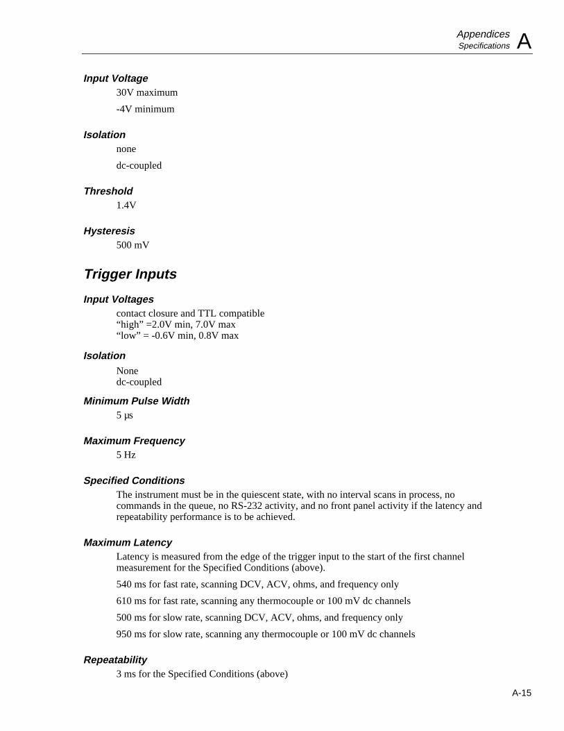
AppendicesSpecifications A
A-15
Input Voltage30V maximum
-4V minimum
Isolationnone
dc-coupled
Threshold1.4V
Hysteresis500 mV
Trigger Inputs
Input Voltagescontact closure and TTL compatible“high” =2.0V min, 7.0V max“low” = -0.6V min, 0.8V max
IsolationNonedc-coupled
Minimum Pulse Width5 µs
Maximum Frequency5 Hz
Specified ConditionsThe instrument must be in the quiescent state, with no interval scans in process, nocommands in the queue, no RS-232 activity, and no front panel activity if the latency andrepeatability performance is to be achieved.
Maximum LatencyLatency is measured from the edge of the trigger input to the start of the first channelmeasurement for the Specified Conditions (above).
540 ms for fast rate, scanning DCV, ACV, ohms, and frequency only
610 ms for fast rate, scanning any thermocouple or 100 mV dc channels
500 ms for slow rate, scanning DCV, ACV, ohms, and frequency only
950 ms for slow rate, scanning any thermocouple or 100 mV dc channels
Repeatability3 ms for the Specified Conditions (above)

2635AUsers Manual
A-16
Digital and Alarm OutputsThe specifications for the digital and alarm outputs are provided in the followingparagraphs.
Output Logic LevelsLogical “zero”: 0.8V max for an Iout of -1.0 mA (1LSTTL load)Logical “one”: 3.8V min for an Iout of 0.05 mA (1LSTTL load)
For non-TTL loads: 1.8V max for an Iout or -20 mALogical “zero”: 3.25 max for an Iout of -50 mA
Isolationnone
Real-Time Clock and CalendarThe specifications for the real-time clock and calendar are provided in the followingparagraphs.
AccuracyWithin 1 minute per month for 0°C to 50°C range
Battery Life>10 unpowered instrument years for 0°C to 28°C
>3 unpowered instrument years for 0°C to 50°C
>2 unpowered instrument years for 50°C to 70°C
Environmental SpecificationsThe environmental specifications are provided in the following paragraphs.
Warmup Time1 hour to rated specifications
15 minutes when relative humidity is kept below the rated maximum minus 20% (e.g.below 70% for a 90% maximum rating).
Operating Temperature0°C to 60°C
Storage Temperature-40°C to +75°C
Instrument storage at temperature extremes may necessitate adding up to 0.008% to thedc and ac voltage accuracy specifications. Alternatively, any resulting shift can becompensated for by recalibrating the instrument.

AppendicesSpecifications A
A-17
Relative Humidity (Non-Condensing)90% maximum for 0°C to 28°C75% maximum for 28°C to 35°C50% maximum for 35°C to 50°C35% maximum for 50°C to 60°C(Except 70% maximum for 0°C to 35°C, 0% maximum for 40°C to 50°C, and 20%maximum for 50°C to 60°C for the 300 ke, 3 Me, and 10 Me ranges.)
Altitude
Operating: 2,000 m maximum
Non-operating: 12,200m maximum
Vibration0.7g at 15 Hz
1.3g at 25 Hz
3g at 55 Hz
Shock30g half sine per Mil-T-28800
Bench handling per Mil-T-28800
GeneralThe general specifications are provided in the following paragraphs.
Channel Capacity21 Analog Inputs
4 Alarm Outputs
8 Digital I/O (inputs/outputs)
Measurement SpeedSlow rate: 4 readings/second nominalFast rate: 17 readings/second nominal
1.5 readings/second nominal for ACV and high-e inputs
For additional information, refer to Typical Scanning Rated and Maximum AutorangingTime.
Nonvolatile Memory Life>10 unpowered instrument years for 0°C to 28°C
>3 unpowered instrument years for 0°C to 50°C
>2 unpowered instrument years for 50°C to 70°C
Stores: Real-time clock, set-up configuration, and measurement data.
Common Mode Voltage300V dc or ac rms maximum from any analog input (channel) to earth provided thatchannel to channel maximum voltage ratings are observed.
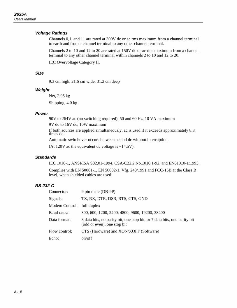
2635AUsers Manual
A-18
Voltage RatingsChannels 0,1, and 11 are rated at 300V dc or ac rms maximum from a channel terminalto earth and from a channel terminal to any other channel terminal.
Channels 2 to 10 and 12 to 20 are rated at 150V dc or ac rms maximum from a channelterminal to any other channel terminal within channels 2 to 10 and 12 to 20.
IEC Overvoltage Category II.
Size
9.3 cm high, 21.6 cm wide, 31.2 cm deep
WeightNet, 2.95 kg
Shipping, 4.0 kg
Power90V to 264V ac (no switching required), 50 and 60 Hz, 10 VA maximum9V dc to 16V dc, 10W maximumIf both sources are applied simultaneously, ac is used if it exceeds approximately 8.3times dc.Automatic switchover occurs between ac and dc without interruption.
(At 120V ac the equivalent dc voltage is ~14.5V).
StandardsIEC 1010-1, ANSI/ISA S82.01-1994, CSA-C22.2 No.1010.1-92, and EN61010-1:1993.
Complies with EN 50081-1, EN 50082-1, Vfg. 243/1991 and FCC-15B at the Class Blevel, when shielded cables are used.
RS-232-CConnector: 9 pin male (DB-9P)
Signals: TX, RX, DTR, DSR, RTS, CTS, GND
Modem Control: full duplex
Baud rates: 300, 600, 1200, 2400, 4800, 9600, 19200, 38400
Data format: 8 data bits, no parity bit, one stop bit, or 7 data bits, one parity bit(odd or even), one stop bit
Flow control: CTS (Hardware) and XON/XOFF (Software)
Echo: on/off

B-1
Appendix BCrosstalk Considerations
IntroductionThis appendix augments the discussion of ac signal effects on other channels (crosstalk).Effects on each measurement function are discussed below. These numbers should onlybe considered as references. Since cross talk can be introduced into a measurementsystem in many places, each setup must be considered individually.
The effect of cross talk could be much better than shown for "Typical"; in extreme cases,the effect could be worse than the "Worst Case" numbers. In general, the "Worst Case"information assumes that none of the guidelines for minimizing cross talk (Chapter 1)have been followed; the "Typical" information assumes that the guidelines have beenfollowed where reasonable.
These numbers assume that input L (low) is tied to earth ground; refer to "UsingShielded Wiring" in Chapter 1. For dc volts and thermocouple temperaturemeasurements, a source impedance of 1 ke in series with the H (high) input is assumed(except where otherwise noted.)
AC Signal Cross Talk in a DC Voltage Channel
DCV Error Ratio (CTRR) =VDC error
VACrms
( )
Worst case Typical
50, 60 Hz, ±0.1%: 1.1 × 10⁻⁷ 2.0 × 10⁻⁸
Other Frequencies: 3.8 × 10⁻⁶ 8.6 × 10⁻⁷
For example, the typical effect on a channel measuring dc volts (300 mV range) by a 300V ac signal at 60 Hz on another channel would be: 300× 2.0× 10-8 = 0.01 mV.

2635AUsers Manual
B-2
AC Signal Cross Talk into an AC Voltage Channel
ACV Error Ratio = VACrms error
VACrms crosstalk Frequency crosstalk
( )
( ) ( )×
Range Ratio (worst case) Ratio (typical)
300.00 m 4.8 × 10⁻⁸ v
v Hz×
1.4 × 10⁻⁸ v
v Hz×
3.0000 V 1.1 × 10⁻⁷ v
v Hz×
3.0 × 10⁻⁸ v
v Hz×
30.000 V 1.2 × 10⁻⁶ v
v Hz×
2.6 × 10⁻⁷ v
v Hz×
150.00/300.00 1.2 × 10⁻⁵ v
v Hz×
3.4 × 10⁻⁶ v
v Hz×
For example, the typical effect on a channel measuring ac volts (300 mV range) by a220V ac signal at 60 Hz on another channel would be: 220 X 60 X 1.4 X 10-8 = 0.18 mV.
AC Signal Cross Talk into an Ohms ChannelAC Frequency = 50, 60 Hz, ±0.1%
OHMS Error Ratio1 = Ohms error
VACrms crosstalk
( )
( )
Range Ratio (worst case) Ratio (typical)
300.00 e 3.3× 10⁻⁵ Ohms
Vrms
NoEffect
3.0000 ke 2.4× 10⁻⁶ kOhms
Vrms
6.7× 10⁻⁷ kOhms
Vrms
30.000ke 3.1× 10⁻⁴ kOhms
Vrms
8.4× 10⁻⁵ kOhms
Vrms
300.00 ke 5.6× 10⁻³ kOhms
Vrms
3.7× 10⁻³ kOhms
Vrms
3.0000 Me 3.8× 10⁻⁴ MOhms
Vrms
3.8× 10⁻⁵ MOhms
Vrms
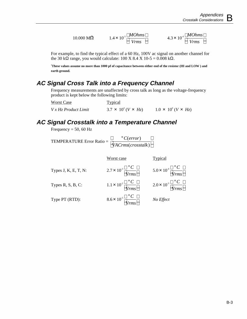
AppendicesCrosstalk Considerations B
B-3
10.000 Me 1.4 × 10⁻³ MOhms
Vrms
4.3 × 10⁻⁴ MOhms
Vrms
For example, to find the typical effect of a 60 Hz, 100V ac signal on another channel forthe 30 kΩ range, you would calculate: 100 X 8.4 X 10-5 = 0.008 kΩ.1These values assume no more than 1000 pf of capacitance between either end of the resistor (HI and LOW ) and
earth ground.
AC Signal Cross Talk into a Frequency ChannelFrequency measurements are unaffected by cross talk as long as the voltage-frequencyproduct is kept below the following limits:
Worst Case Typical
V x Hz Product Limit 3.7 × 10⁴ (V × Hz) 1.0 × 10⁶ (V × Hz)
AC Signal Crosstalk into a Temperature ChannelFrequency = 50, 60 Hz
TEMPERATURE Error Ratio = °
C error
VACrms crosstalk
( )
( )
Worst case Typical
Types J, K, E, T, N: 2.7 × 10⁻³ °
C
Vrms5.0 × 10-4 °
C
Vrms
Types R, S, B, C: 1.1 × 10⁻² °
C
Vrms2.0 × 10-3 °
C
Vrms
Type PT (RTD): 8.6 × 10⁻⁵ °
C
VrmsNo Effect

2635AUsers Manual
B-4

C-1
Appendix CBinary Upload of Logged Data
IntroductionThe LOG_BIN? <index> query can be used to quickly upload logged data from a 2635A.The response is a single ASCII string, which encodes the raw binary data stored at thespecified <index> position. The logged data is also retained in the 2635A.
The measurement data returned from the 2635A is in the (binary) IEEE single-precisionfloating point format. Making use of this data can be difficult and is very machinedependent. A working example, using the C programming language on an IBM PC, isprovided in this appendix. This example uses a pre-computed LOG_BIN?responsestring, and checks that the conversion process works as expected.
Two steps are required in adapting the LOG_BIN? response string for use with yourcomputer.
• First, you must decode the ASCII string into binary data.
For example, one possible LOG_BIN? response string is:
LOG_BIN? 1
42@Y40BA00oo000007o0001oP000?h000
=>
This ASCII string represents the following binary (hex) data:
10 24 29 10 04 91 00 0f ff
00 00 00 00 7f c0 00 00 7f
80 00 00 3f 80 00 00 00 00
• Second, you must convert this binary data into valid floating point numbers for yourunderlying computer architecture.
Decoding the ASCII StringThe ASCII response string contains six bits of raw data for each ASCII character, offsetfrom ASCII ’0’ (0x30 hex, 48 decimal). Therefore, the conversion process subtracts 48from the integer value of each character, then shifts it into place. Each set of four ASCIIcharacters form three bytes of raw data. The number of bytes of raw data depends on the

2635AUsers Manual
C-2
number of channels for the scan. The following C code converts a LOG_BIN? responsestring into a byte array:
/*
-* decode(): Decode LOG_BIN? response string into raw byte stream
**
** Decoding is done on multiples of four input bytes:
**
** 543210 543210 543210 543210 (bit number in ASCII bytes)
** +--------+--------+--------+--------+
** | src[0] | src[1] | src[2] | src[3] | ASCII string input
** +--------+--------+--------+--------+
** 765432 107654 321076 543210 (bit number in raw bytes)
** / / /
** / / /
** | / /
** | / /
** | | /
** | | /
** | | |
** 76543210 76543210 76543210 (bit number in raw bytes)
** +--------+--------+--------+
** | dst[0] | dst[1] | dst[2] | Raw data output
** +--------+--------+--------+
**
** Inputs:
** dst Destination for binary data (must have enough space
** allocated; the maximum needed is 6 timestamp bytes + 3
** bytes for temp units, measurement rate, and digital I/O
** + 4 bytes/float * 22 floating point values = 97 bytes).
**
** src Source ASCII string (null terminated)
**
** Outputs:
** dst Set to binary data, based on ASCII string
**
** Returns:
** Number of bytes placed in destination buffer
*/
int
decode(dst, src)
unsigned char *dst;
char *src;
/* src to dst xlate */
static struct nibtab_s
int lindex;
int lmask;
int lshift;
int rindex;
int rmask;
int rshift;
nibtab[3] =
/* left right */

AppendicesBinary Upload of Logged Data C
C-3
0, 0x3f, 2, 1, 0x30, 4, /* dst[0] from src[0] and src[1] */
1, 0x0f, 4, 2, 0x3c, 2, /* dst[1] from src[1] and src[2] */
2, 0x03, 6, 3, 0x3f, 0, /* dst[2] from src[2] and src[3] */
;
auto unsigned char n;
auto struct nibtab_s *t;
auto unsigned char tmpsrc[4];
auto int dst_bytes;
/* Number of bytes created */
dst_bytes = 0;
/* Process src in chunks of four */
while (*src)
/* Copy source, filing "holes" at end with zeros */
for (n = 0; n < 4; n++)
if (*src)
tmpsrc[n] = *src++ - ’0’;
else
tmpsrc[n] = 0;
/* Mung source into destination */
for (t = nibtab; t < &nibtab[3]; t++)
*dst = (tmpsrc[t->lindex] & t->lmask) << t->lshift;
*dst |= (tmpsrc[t->rindex] & t->rmask) >> t->rshift;
dst++;
dst_bytes++;
return (dst_bytes);
Figure C-1. ASCII String Decoding
The raw data output array contains the information listed below. Note that the number offloating point values is equal to the number of channels in use, plus one. (The totalizercount is always present in the data, and is stored as a floating point number.)
• Time stamp (BCD format)
byte0: hours
byte1: minutes
byte2: seconds
byte3: month
byte4: date
byte5: year
• Temperature units, measurement rate, and I/O
2635AUsers Manual
C-4
byte6: temperature units and rate (0x10 bit means degrees Fahrenheit, elseCentigrade; 0x01 bit means fast rate, else slow rate)
byte7: Alarm outputs
byte8: Digital I/O
• Totalizer value as 32-bit single-precision IEEE floating point number stored usingthe byte ordering shown below. The format of this number is explained under"Floating Point Conversion".
byte 9: MMSB of float
byte 10: MLSB of float
byte 11: LMSB of float
byte 12: LLSB of float
• Measurement data; only defined channels are included (exactly like LOG?query);same floating point format, but with a wider range of values. NaN (Not a Number)is used to indicate open thermocouple, and plus or minus Inf (infinity) to indicateoverload. The bit values for NaN and Inf are explained in the next section.
byte 13: MMSB of float
byte 14: MLSB of float
byte 15: LMSB of float
byte 16: LLSB of float
bytes 17-20: Second measurement result, if any
bytes 21-24: Third measurement result, if any
...
Since the ASCII decoding (explained above) creates data multiples of three in length, itis possible that there will be one or two unused bytes at the end of the decoded bytestream.
Floating Point ConversionANSI/IEEE Std 754-1985, "IEEE Standard for Binary Floating-Point Arithmetic,"describes the single-precision floating point format used to return measurement data.This standard defines the format for single-precision floating point as:
X = (-1) s 2 (e-127) (1.m )
where
s = sign
e = exponent
m = mantissa
The floating point format used is 32-bit with a 1-bit sign, 8-bit exponent, and 24-bitmantissa with the most significant bit hidden under the LSB of the exponent. Thenumber is formatted as shown in Table C-1.
For all other measurement queries, Hydra Series II returns the string "+9E+9" for openthermocouple (OTC) measurement values. However, for the LOG_BIN?query, NaN (nota number) is returned instead. The IEEE floating point standard defines NaN as apositive, maximum exponent number with non-zero mantissa bits. Hydra Series II sets

AppendicesBinary Upload of Logged Data C
C-5
just the most significant mantissa bit, so the raw binary byte stream value is 7f c0 00 00(hex).
For all other measurement queries, Hydra Series II usually returns ±1e9 for overload(OL) measurement values. However, for the LOG_BIN? query, Hydra Series II returnsInf (infinity) instead. The IEEE floating point standard defines Inf as a positive ornegative maximum exponent number with a zero mantissa. Hydra Series II returns +Infas the byte stream 7f 80 00 00 (hex) and -Inf as ff 80 00 00 (hex).
Table C-1. Floating-Point Format
Sign
1 bit
Exponent
8 bits
Manitssa
23 bits (plus one hidden bit)
high byte
(MMSB)
High-mid byte
(MLSB)
low-mid bute
(LMSB)
low byte
(LLSB)
The C code in Figure C-2 converts raw data into a useful format for the Intel x86 (IBMPC) architecture. The BCD time stamp is converted to integers, and floating pointnumbers created for the totalizer and measurement values.

2635AUsers Manual
C-6
/* Import globals from main program */extern int timestamp[];extern int misc[];extern float values[];
/*-* convert(): Convert a LOG_BIN? array of binary data into useful data**** Converts BCD values to integer, raw floating point values into float** values usable under the Intel x86 (IBM PC) architecture.**** Inputs:** src Array of binary data, from LOG_BIN? query** length Number of bytes in src array**** Outputs:** timestamp[] Set to decimal timestamp values** misc[] Set to temp units, rate, and digital I/O values** values[] Set to floating point values found in binary data** (must be room for a maximum of 22 floats)*/
voidconvert(src, length) unsigned char *src; int length; unsigned char *m; int n;
/* Convert timestamp from BCD to decimal */ for (n=0; n < 6; n++, src++) /* Binary Coded Decimal (BCD) format, packs the upper nibble as the*/ /* tens digit, the lower nibble as the ones digit. Convert this*/ /* into an integer number.*/ timestamp[n] = (10 * (*src >> 4) + (*src & 0x0f));
/* Save temperature units, measurement rate, and digital I/O values */ for (n=0; n < 3; n++) misc[n] = *src++;
/* Convert raw measurement data into floating point */ m = (unsigned char *)values; for (length -= 9; length > 3; length -= 4)
#ifdef sun /* SunOS architecture (also works for Motorola CPUs) */ *m++ = src[0]; *m++ = src[1]; *m++ = src[2]; *m++ = src[3];#else /* Assume Intel x86 architecture */ *m++ = src[3]; *m++ = src[2]; *m++ = src[1]; *m++ = src[0];#endif src += 4;
Figure C-2. Floating_Point Conversion

AppendicesBinary Upload of Logged Data C
C-7
ExampleFigure C-3 is a short example that uses the routines in Figures C-1 and C-2 to decode afixed (pre-computed) LOG_BIN? response string.
When compiled and run on an Intel architecture computer, the program should print"Conversion worked".
Although this example is useful for educational purposes, it is not very efficient. Ifdesired, the decoding and conversion processes can be combined into a single, fastalgorithm.

2635AUsers Manual
C-8
/* Globals convert() uses for destination */
int timestamp[6]; /* Scan timestamp */int misc[3]; /* Temperature units, measurement rate, digital I/O */float values[22]; /* Measurement values */
extern int isnan(); /* Floating point value is NaN (not a number) */extern int isinf(); /* Floating point value is Inf (infinity) */
/*-* main(): LOG_BIN? query response example program**** Converts a hard-coded LOG_BIN? response string into usable data.*/
main() extern int decode(); /* ASCII to binary decoding */ extern void convert(); /* Convert Hydra binary to usable types */
/* Canned response for three channels: channel 1 is OTC, channel 5 is */ /* OL and channel 10 is 1.0; remaining encoded data described below */ /* (note that you can not determine the channel number, measurement */ /* units, or measurement range, from this string; you must keep track */ /* of that elsewhere) */ char *log_bin_response = "42@Y40BA00oo000007o0001oP000?h000";
/* Place to temporarily store raw data; 100 bytes is more than enough */ /* for any LOG_BIN? response string */ unsigned char raw_data[100];
/* Decode string into raw data, then convert raw data into usable data */ convert(raw_data, decode(raw_data, log_bin_response));
/* Above global variables now usable; check example LOG_BIN? data */ /* against expected values */
if ((timestamp[0] == 10) && /* Hours */ (timestamp[1] == 24) && /* Minutes */ (timestamp[2] == 29) && /* Seconds */ (timestamp[3] == 10) && /* Month */ (timestamp[4] == 4) && /* Day */ (timestamp[5] == 91) && /* Year */ (misc[0] == 0) && /* Temp units and rate */ (misc[1] == 15) && /* Alarm outputs */ (misc[2] == 255) && /* Digital I/O */ (values[0] == 0.0) && /* Totalizer */ isnan(values[1]) && /* Channel 1 data */ isinf(values[2]) && /* Channel 5 data */ (values[3] == 1.0)) /* Channel 10 data */
printf("Conversion worked\n"); else printf("ERROR: conversion did not succeed!\n");
exit(0);
/* If your math library supplies alternatives to isnan() or isinf(), *//* use them instead! */
intisnan(f) float f; /* This is not portable, or completely accurate (since NaN mantissa */ /* must only be non-zero, and the sign bit can be set), but this works */ /* for NaN values returned by Hydra */
/* Compiler was free to promote to double */ float ff = f;
return ((*(unsigned long *)&ff) == 0x7fc00000L);
intisinf(f) float f;
/* Again, this is not portable, but this time it is accurate */
/* Compiler was free to promote to double */ float ff = f;
return ((*(unsigned long *)&ff) == 0x7f800000L) || ((*(unsigned long *)&ff) == 0xff800000L);
Figure C-3. Example

D-1
Appendix DRS-232 Cabling
IntroductionThis appendix details the RS-232 cabling between the instrument and a PC, instrumentcontroller (Fluke 17XXA series), printer, or modem. All connections can be made usingthe Fluke RS-series of cables (see Options and Accessories in Chapter 1). RS-232 cablesshould not exceed 50 feet (15 meters) although longer cables are permitted if the loadcapacitance measured at a connection point (including signal terminator) does notexceed 2500 picofarads. The Fluke RS cables are 6 feet (1.83 meters) in length.
ConnectionsFigure D-1 summarizes the cable requirements for all typical RS-232 connections;Figure D-2 through E-6 summarize instrument cabling diagrams; Figure D-7 shows thepin arrangement for DB-9 and DB-25 connectors. There are two wiring schemes(modem and null-modem), two types of connectors (DB-9 and DB-25), two cable endconditions (male and female), and two equipment configurations (Data TerminalEquipment [DTE] and Data Communications Equipment [DCE]). Because of variationsin RS-232 connectors, it is not possible to identify all possible configurations. In thisapplication, “null-modem” refers to a reversing of the following lines; receive (RX) andtransmit (TX), data terminal ready (DTR) and data set ready (DSR), and request to send(RTS) and clear to send (CTS). Not all interfaces use all lines. Check the documentationfor the equipment you are interfacing with the instrument.
CablesThe Fluke RS-series of RS-232 cables are in the following standard configurations:
• RS40 - Null modem with DB-9/female and DB-25/female connectors• RS41 - Modem with DB-9/female and DB-25/male connectors• RS42 - Null modem with DB-9/female and DB-25/male connectors
Cables from other sources may be used, or cables can be fabricated based on the figuresin this appendix. The RS40 and RS42 cables are identical, except for the DB-25connectors (female and male, respectively). Some interfaces allow a selection of cables.
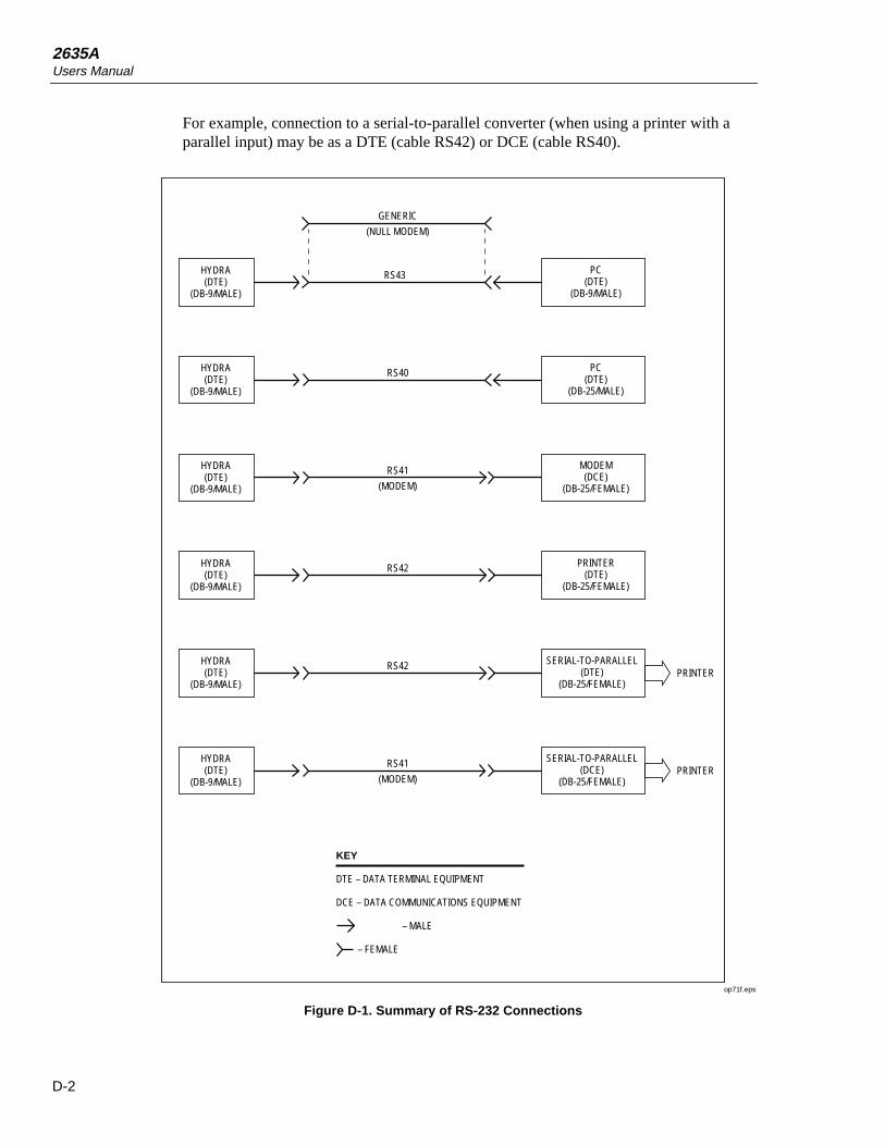
2635AUsers Manual
D-2
For example, connection to a serial-to-parallel converter (when using a printer with aparallel input) may be as a DTE (cable RS42) or DCE (cable RS40).
HYDRA(DTE)
(DB-9/MALE)
RS43
HYDRA(DTE)
(DB-9/MALE)
PC(DTE)
(DB-9/MALE)
RS40
HYDRA(DTE)
(DB-9/MALE)
PC(DTE)
(DB-25/MALE)
RS41
(MODEM)
HYDRA(DTE)
(DB-9/MALE)
MODEM(DCE)
(DB-25/FEMALE)
RS42
HYDRA(DTE)
(DB-9/MALE)
PRINTER(DTE)
(DB-25/FEMALE)
RS42
HYDRA(DTE)
(DB-9/MALE)
SERIAL-TO-PARALLEL(DTE)
(DB-25/FEMALE)
RS41
(MODEM)
GENERIC
(NULL MODEM)
SERIAL-TO-PARALLEL(DCE)
(DB-25/FEMALE)
PRINTER
PRINTER
KEY
DTE – DATA TERMINAL EQUIPMENT
DCE – DATA COMMUNICATIONS EQUIPMENT
– MALE
– FEMALE
op71f.eps
Figure D-1. Summary of RS-232 Connections

AppendicesRS-232 Cabling D
D-3
Rx
Tx
DTR
GND
DSR
RTS
CTS
1
2
3
4
5
6
7
8
9
RS-232C
HYDRA
DB-9
DCD
Rx
Tx
DTR
GND
DSR
RTS
CTS
RI
1
2
3
4
5
6
7
8
9
COM
PC
DB-9
RS43 CABLE(NULL MODEM)
FEMALE
MALE
PINS KEY
DCD – DATA CARRIER DETECT
Rx – RECEIVE
Tx – TRANSMIT
DTR – DATA TERMINAL READY
GND – GROUND
DSR – DATA SET READY
RTS – REQUEST TO SEND
CTS – CLEAR TO SEND
RI – RING INDICATOR
op73f.eps
Figure D-2. Hydra Series II (DB-9) to PC (DB-9) RS-232 Connection (Generic)
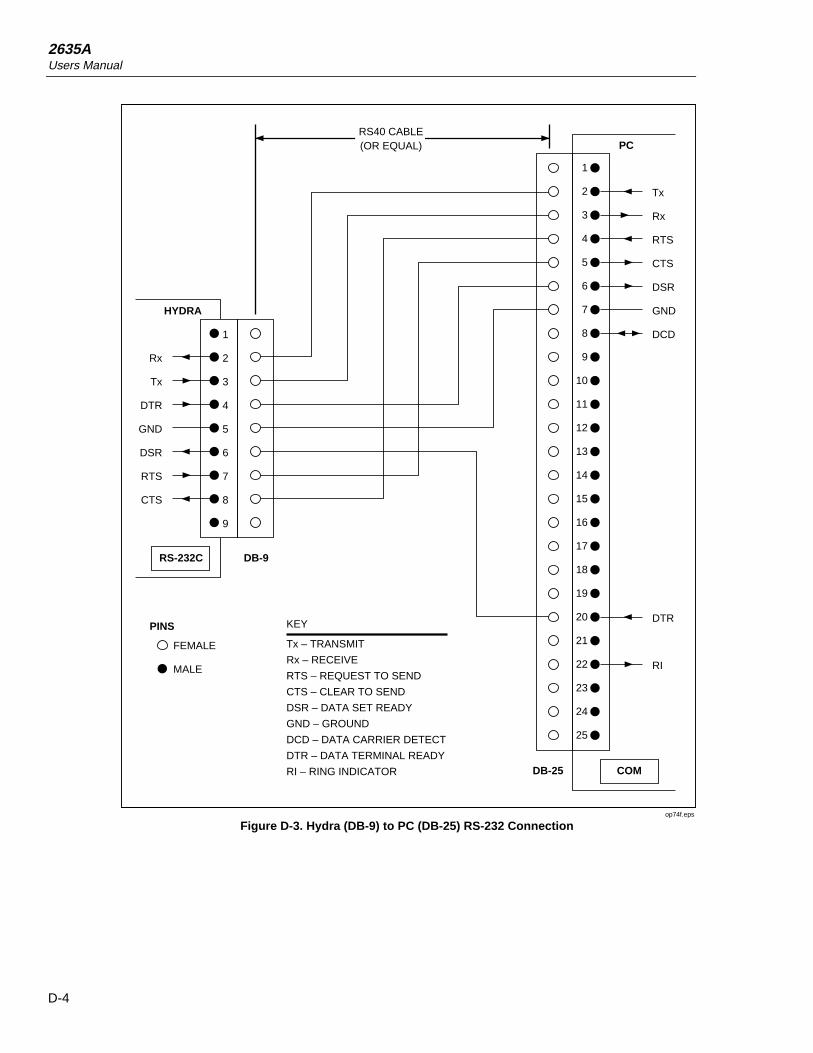
2635AUsers Manual
D-4
Rx
Tx
DTR
GND
DSR
RTS
CTS
1
2
3
4
5
6
7
8
9
RS-232C
HYDRA
DB-9
Tx
Rx
RTS
CTS
DSR
GND
DCD
DTR
RI
COM
PC
DB-25
RS40 CABLE(OR EQUAL)
FEMALE
MALE
PINS KEY
Tx – TRANSMIT
Rx – RECEIVE
RTS – REQUEST TO SEND
CTS – CLEAR TO SEND
DSR – DATA SET READY
GND – GROUND
DCD – DATA CARRIER DETECT
DTR – DATA TERMINAL READY
RI – RING INDICATOR
1
2
3
4
5
6
7
8
9
10
11
12
13
14
15
16
17
18
19
20
21
22
23
24
25
op74f.eps
Figure D-3. Hydra (DB-9) to PC (DB-25) RS-232 Connection
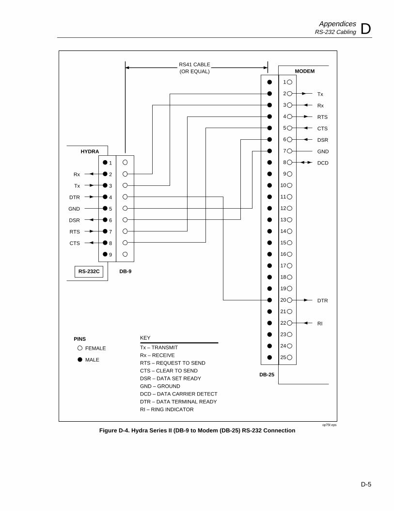
AppendicesRS-232 Cabling D
D-5
Rx
Tx
DTR
GND
DSR
RTS
CTS
1
2
3
4
5
6
7
8
9
RS-232C
HYDRA
DB-9
Tx
Rx
RTS
CTS
DSR
GND
DCD
DTR
RI
MODEM
DB-25
RS41 CABLE(OR EQUAL)
FEMALE
MALE
PINS KEY
Tx – TRANSMIT
Rx – RECEIVE
RTS – REQUEST TO SEND
CTS – CLEAR TO SEND
DSR – DATA SET READY
GND – GROUND
DCD – DATA CARRIER DETECT
DTR – DATA TERMINAL READY
RI – RING INDICATOR
1
2
3
4
5
6
7
8
9
10
11
12
13
14
15
16
17
18
19
20
21
22
23
24
25
op75f.eps
Figure D-4. Hydra Series II (DB-9 to Modem (DB-25) RS-232 Connection

2635AUsers Manual
D-6
Rx
Tx
DTR
GND
DSR
RTS
CTS
1
2
3
4
5
6
7
8
9
RS-232C
HYDRA
DB-9
Tx
Rx
RTS
CTS
DSR
GND
DCD
DTR
RI
PRINTER
DB-25
RS42 CABLE(OR EQUAL)
FEMALE
MALE
PINS KEY
Tx – TRANSMIT
Rx – RECEIVE
RTS – REQUEST TO SEND
CTS – CLEAR TO SEND
DSR – DATA SET READY
GND – GROUND
DCD – DATA CARRIER DETECT
DTR – DATA TERMINAL READY
RI – RING INDICATOR
1
2
3
4
5
6
7
8
9
10
11
12
13
14
15
16
17
18
19
20
21
22
23
24
25
op76f.eps
Figure D-5. Hydra Series II (DB-9) to Printer (DB-25) RS-232 Connection
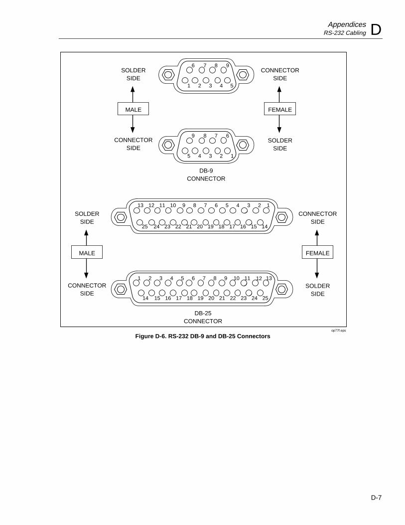
AppendicesRS-232 Cabling D
D-7
DB-9CONNECTOR
CONNECTORSIDE
DB-25CONNECTOR
SOLDERSIDE
FEMALE
CONNECTORSIDE
SOLDERSIDE
MALE
CONNECTORSIDE
SOLDERSIDE
FEMALE
CONNECTORSIDE
SOLDERSIDE
MALE
6
1
9
5
7
2
8
4
8
3
7
3
9
4
6
2 1
5
12
25
2
14
1
13 11
24
3
15
10
23
4
16
9
22
5
17
8
21
6
18
7
20
7
19
6
19
8
20
5
18
9
21
4
17
10
22
3
16
11
23
2
15
12
24
1
14
13
25
op77f.eps
Figure D-6. RS-232 DB-9 and DB-25 Connectors

2635AUsers Manual
D-8

E-1
Appendix E8-Bit Binary-Coded-Decimal Table

2635AUsers Manual
E-2
Table E-1. 8-Bit Binary-Coded-Decimal
Binary Binary Binary Binary7 6 5 4 3 2 1 0 Dec 7 6 5 4 3 2 1 0 Dec 7 6 5 4 3 2 1 0 Dec 7 6 5 4 3 2 1 0 Dec
0 0 0 0 0 0 0 0 000 0 1 0 0 0 0 0 0 064 1 0 0 0 0 0 0 0 128 1 1 0 0 0 0 0 0 1920 0 0 0 0 0 0 1 001 0 1 0 0 0 0 0 1 065 1 0 0 0 0 0 0 1 129 1 1 0 0 0 0 0 1 1930 0 0 0 0 0 1 0 002 0 1 0 0 0 0 1 0 066 1 0 0 0 0 0 1 0 130 1 1 0 0 0 0 1 0 1940 0 0 0 0 0 1 1 003 0 1 0 0 0 0 1 1 067 1 0 0 0 0 0 1 1 131 1 1 0 0 0 0 1 1 1950 0 0 0 0 1 0 0 004 0 1 0 0 0 1 0 0 068 1 0 0 0 0 1 0 0 132 1 1 0 0 0 1 0 0 1960 0 0 0 0 1 0 1 005 0 1 0 0 0 1 0 1 069 1 0 0 0 0 1 0 1 133 1 1 0 0 0 1 0 1 1970 0 0 0 0 1 1 0 006 0 1 0 0 0 1 1 0 070 1 0 0 0 0 1 1 0 134 1 1 0 0 0 1 1 0 1980 0 0 0 0 1 1 1 007 0 1 0 0 0 1 1 1 071 1 0 0 0 0 1 1 1 135 1 1 0 0 0 1 1 1 1990 0 0 0 1 0 0 0 008 0 1 0 0 1 0 0 0 072 1 0 0 0 1 0 0 0 136 1 1 0 0 1 0 0 0 2000 0 0 0 1 0 0 1 009 0 1 0 0 1 0 0 1 073 1 0 0 0 1 0 0 1 137 1 1 0 0 1 0 0 1 2010 0 0 0 1 0 1 0 010 0 1 0 0 1 0 1 0 074 1 0 0 0 1 0 1 0 138 1 1 0 0 1 0 1 0 2020 0 0 0 1 0 1 1 011 0 1 0 0 1 0 1 1 075 1 0 0 0 1 0 1 1 139 1 1 0 0 1 0 1 1 2030 0 0 0 1 1 0 0 012 0 1 0 0 1 1 0 0 076 1 0 0 0 1 1 0 0 140 1 1 0 0 1 1 0 0 2040 0 0 0 1 1 0 1 013 0 1 0 0 1 1 0 1 077 1 0 0 0 1 1 0 1 141 1 1 0 0 1 1 0 1 2050 0 0 0 1 1 1 0 014 0 1 0 0 1 1 1 0 078 1 0 0 0 1 1 1 0 142 1 1 0 0 1 1 1 0 2060 0 0 0 1 1 1 1 015 0 1 0 0 1 1 1 1 079 1 0 0 0 1 1 1 1 143 1 1 0 0 1 1 1 1 2070 0 0 1 0 0 0 0 016 0 1 0 1 0 0 0 0 080 1 0 0 1 0 0 0 0 144 1 1 0 1 0 0 0 0 2080 0 0 1 0 0 0 1 017 0 1 0 1 0 0 0 1 081 1 0 0 1 0 0 0 1 145 1 1 0 1 0 0 0 1 2090 0 0 1 0 0 1 0 018 0 1 0 1 0 0 1 0 082 1 0 0 1 0 0 1 0 146 1 1 0 1 0 0 1 0 2100 0 0 1 0 0 1 1 019 0 1 0 1 0 0 1 1 083 1 0 0 1 0 0 1 1 147 1 1 0 1 0 0 1 1 2110 0 0 1 0 1 0 0 020 0 1 0 1 0 1 0 0 084 1 0 0 1 0 1 0 0 148 1 1 0 1 0 1 0 0 2120 0 0 1 0 1 0 1 021 0 1 0 1 0 1 0 1 085 1 0 0 1 0 1 0 1 149 1 1 0 1 0 1 0 1 2130 0 0 1 0 1 1 0 022 0 1 0 1 0 1 1 0 086 1 0 0 1 0 1 1 0 150 1 1 0 1 0 1 1 0 2140 0 0 1 0 1 1 1 023 0 1 0 1 0 1 1 1 087 1 0 0 1 0 1 1 1 151 1 1 0 1 0 1 1 1 2150 0 0 1 1 0 0 0 024 0 1 0 1 1 0 0 0 088 1 0 0 1 1 0 0 0 152 1 1 0 1 1 0 0 0 2160 0 0 1 1 0 0 1 025 0 1 0 1 1 0 0 1 089 1 0 0 1 1 0 0 1 153 1 1 0 1 1 0 0 1 2170 0 0 1 1 0 1 0 026 0 1 0 1 1 0 1 0 090 1 0 0 1 1 0 1 0 154 1 1 0 1 1 0 1 0 2180 0 0 1 1 0 1 1 027 0 1 0 1 1 0 1 1 091 1 0 0 1 1 0 1 1 155 1 1 0 1 1 0 1 1 2190 0 0 1 1 1 0 0 028 0 1 0 1 1 1 0 0 092 1 0 0 1 1 1 0 0 156 1 1 0 1 1 1 0 0 2200 0 0 1 1 1 0 1 029 0 1 0 1 1 1 0 1 093 1 0 0 1 1 1 0 1 157 1 1 0 1 1 1 0 1 2210 0 0 1 1 1 1 0 030 0 1 0 1 1 1 1 0 094 1 0 0 1 1 1 1 0 158 1 1 0 1 1 1 1 0 2220 0 0 1 1 1 1 1 031 0 1 0 1 1 1 1 1 095 1 0 0 1 1 1 1 1 159 1 1 0 1 1 1 1 1 2230 0 1 0 0 0 0 0 032 0 1 1 0 0 0 0 0 096 1 0 1 0 0 0 0 0 160 1 1 1 0 0 0 0 0 2240 0 1 0 0 0 0 1 033 0 1 1 0 0 0 0 1 097 1 0 1 0 0 0 0 1 161 1 1 1 0 0 0 0 1 2250 0 1 0 0 0 1 0 034 0 1 1 0 0 0 1 0 098 1 0 1 0 0 0 1 0 162 1 1 1 0 0 0 1 0 2260 0 1 0 0 0 1 1 035 0 1 1 0 0 0 1 1 099 1 0 1 0 0 0 1 1 163 1 1 1 0 0 0 1 1 2270 0 1 0 0 1 0 0 036 0 1 1 0 0 1 0 0 100 1 0 1 0 0 1 0 0 164 1 1 1 0 0 1 0 0 2280 0 1 0 0 1 0 1 037 0 1 1 0 0 1 0 1 101 1 0 1 0 0 1 0 1 165 1 1 1 0 0 1 0 1 2290 0 1 0 0 1 1 0 038 0 1 1 0 0 1 1 0 102 1 0 1 0 0 1 1 0 166 1 1 1 0 0 1 1 0 2300 0 1 0 0 1 1 1 039 0 1 1 0 0 1 1 1 103 1 0 1 0 0 1 1 1 167 1 1 1 0 0 1 1 1 2310 0 1 0 1 0 0 0 040 0 1 1 0 1 0 0 0 104 1 0 1 0 1 0 0 0 168 1 1 1 0 1 0 0 0 2320 0 1 0 1 0 0 1 041 0 1 1 0 1 0 0 1 105 1 0 1 0 1 0 0 1 169 1 1 1 0 1 0 0 1 2330 0 1 0 1 0 1 0 042 0 1 1 0 1 0 1 0 106 1 0 1 0 1 0 1 0 160 1 1 1 0 1 0 1 0 2340 0 1 0 1 0 1 1 043 0 1 1 0 1 0 1 1 107 1 0 1 0 1 0 1 1 171 1 1 1 0 1 0 1 1 2350 0 1 0 1 1 0 0 044 0 1 1 0 1 1 0 0 108 1 0 1 0 1 1 0 0 172 1 1 1 0 1 1 0 0 2360 0 1 0 1 1 0 1 045 0 1 1 0 1 1 0 1 109 1 0 1 0 1 1 0 1 173 1 1 1 0 1 1 0 1 2370 0 1 0 1 1 1 0 046 0 1 1 0 1 1 1 0 110 1 0 1 0 1 1 1 0 174 1 1 1 0 1 1 1 0 2380 0 1 0 1 1 1 1 047 0 1 1 0 1 1 1 1 111 1 0 1 0 1 1 1 1 175 1 1 1 0 1 1 1 1 2390 0 1 1 0 0 0 0 048 0 1 1 1 0 0 0 0 112 1 0 1 1 0 0 0 0 176 1 1 1 1 0 0 0 0 2400 0 1 1 0 0 0 1 049 0 1 1 1 0 0 0 1 113 1 0 1 1 0 0 0 1 177 1 1 1 1 0 0 0 1 2410 0 1 1 0 0 1 0 050 0 1 1 1 0 0 1 0 114 1 0 1 1 0 0 1 0 178 1 1 1 1 0 0 1 0 2420 0 1 1 0 0 1 1 051 0 1 1 1 0 0 1 1 115 1 0 1 1 0 0 1 1 179 1 1 1 1 0 0 1 1 2430 0 1 1 0 1 0 0 052 0 1 1 1 0 1 0 0 116 1 0 1 1 0 1 0 0 180 1 1 1 1 0 1 0 0 2440 0 1 1 0 1 0 1 053 0 1 1 1 0 1 0 1 117 1 0 1 1 0 1 0 1 181 1 1 1 1 0 1 0 1 2450 0 1 1 0 1 1 0 054 0 1 1 1 0 1 1 0 118 1 0 1 1 0 1 1 0 182 1 1 1 1 0 1 1 0 2460 0 1 1 0 1 1 1 055 0 1 1 1 0 1 1 1 119 1 0 1 1 0 1 1 1 183 1 1 1 1 0 1 1 1 2470 0 1 1 1 0 0 0 056 0 1 1 1 1 0 0 0 120 1 0 1 1 1 0 0 0 184 1 1 1 1 1 0 0 0 2480 0 1 1 1 0 0 1 057 0 1 1 1 1 0 0 1 121 1 0 1 1 1 0 0 1 185 1 1 1 1 1 0 0 1 2490 0 1 1 1 0 1 0 058 0 1 1 1 1 0 1 0 122 1 0 1 1 1 0 1 0 186 1 1 1 1 1 0 1 0 2500 0 1 1 1 0 1 1 059 0 1 1 1 1 0 1 1 123 1 0 1 1 1 0 1 1 187 1 1 1 1 1 0 1 1 2510 0 1 1 1 1 0 0 060 0 1 1 1 1 1 0 0 124 1 0 1 1 1 1 0 0 188 1 1 1 1 1 1 0 0 2520 0 1 1 1 1 0 1 061 0 1 1 1 1 1 0 1 125 1 0 1 1 1 1 0 1 189 1 1 1 1 1 1 0 1 2530 0 1 1 1 1 1 0 062 0 1 1 1 1 1 1 0 126 1 0 1 1 1 1 1 0 190 1 1 1 1 1 1 1 0 2540 0 1 1 1 1 1 1 063 0 1 1 1 1 1 1 1 127 1 0 1 1 1 1 1 1 191 1 1 1 1 1 1 1 1 255

F-1
Appendix FMemory Card File Formats
IntroductionThis appendix contains a description of the format of the binary files created by the2635A Data Bucket. This information is intended to describe the contents in enoughdetail to allow someone well versed in a software programming language to use thisinformation to write software to read and interpret the Data Bucket scan data files. (Thisexample ;uses the ANSI C Language to examples of decoding and interpreting the filedata. This code can be compiled using the Microsoft C Compiler on an MS-DOS PC orcompatible.)
Data File FormatThe data file format consists of two parts: a header, including the Data Bucketconfiguration during the time the data was gathered: followed by any scan data collected.
Setup File FormatThe setup file format is very similar to the data file format. The only differences are thebyte at offset zero has a value of 0 instead of 1, and there is never any scan data (the filealways ends at offset 729).
The details of the Hydra Data Bucket binary file configuration format are as follows. Agood familiarity with the operation of the Hydra Data Bucket will be necessary tounderstand much of the configuration information. For the most part, however, it is notnecessary to understand all of the configuration information to be able to successfullymanipulate the scan data. The references are to compute interface commands in Chapter4.

2635AUsers Manual
F-2
Offset Description ===== =========== 0 File type; 0 for setup files, 1 for data files. 1 File format; always zero for this format. 2-81 Tag string. Copied from the setup file used with a time string appended; or just a time string if no setup file used. 82 Set up format version; always zero. 83 Global instrument configuration; 0x01 bit set for degrees Fahrenheit, else Centigrade; 0x02 bit set for open thermocouple checking enabled; 0x80 bit set for alarms on open thermocouple. See TEMP_CONFIG. 84 Measurement rate; 0 for slow, 1 for fast. See RATE. 85 Trigger type; 0 for off, 1 for on, 2 for monitor alarm. See TRIGGER. 86 Output format type; 1 for no units, 2 for units. See FORMAT. 87 Totalizer debounce; 0 for off, 1 for on. See TOTAL_DBNC. 88 Interval BCD hours. See INTERVAL. 89 Interval BCD minutes. 90 Interval BCD seconds. 91 Event Status Register (ESR) value. 92 Service Request Enable (ESE) register value. 93 Instrument Event Enable (IEE) register value. 94 Logging status; 0x1 bit set if logging enabled, 0x02 bit set if LOG queue stops logging when full. See LOG_MODE. 95 Logging filter; 0 for all, 1 for alarms, 2 for alarm transitions. See PRINT_TYPE. 96 Logging destination; 0x01 bit for printer, 0x02 bit set for LOG queue, 0x04 bit set for memory card. See PRINT_TYPE. 97 Front panel lock mode; 0 for not locked, 3 for configuration lock. See LOCK. 98-727 Channel definitions:
Offset within each channel definition Description ——— ———------—— 0 Measurement. 0 if off, 1 if vdc, 2 if vac, 3 if ohms, 4 if frequency, 9 if thermocouple, 11 if RTD. 1 Measurement range. Lower bit values are measurement range, with 0 being the lowest range for the measurement type (e.g., 0 for 300 mVDC). 0x10 bit set if autoranging. See RANGE? 2 Thermocouple/RTD type. 0 for Pt, 1 for J, 2 for K, 3 for E, 4 for T, 5 for N, 6 for R, 7 for S, 8 for B, 9 for C. 3 Alarm flags. 0x01 bit set for limit 1 (SP1) low, 0x02 bit set for SP1 high, 0x04 bit set for limit 2 (SP2) low, 0x08 bit set for SP2 high. See ALARM_LIMIT. 4-7 Alarm limit 1 (4-byte single-precision floating point). 8-11 Alarm limit 2 (4-byte single-precision floating point). 12 Alarm 1 digital I/O association. See ALARM_ASSOC. 13 Alarm 1 display range. See SCALE_MB (DISPLAY CODE - 1). 14 Alarm 2 digital I/O association. See ALARM_ASSOC. 15 Alarm 2 display range. See SCALE_MB (DISPLAY CODE - 1). 16-19 Mx+B M value (floating point). 20-23 Mx+B B value (floating point). 24 Mx+B M display range. See SCALE_MB (DISPLAY CODE - 1). 25 MX+B B display range. See SCALE_MB (DISPLAY CODE - 1). 26-29 RTD R0 value (floating point). See RTD_R0.
728-729 CRC-16 of the data from offset 82 to 727.

AppendicesMemory Card File Formats F
F-3
For a data file, any scan data would immediately follow the configuration information.Note that it is very possible to have no scan data if the data file is created but scanning isnever done.
Measurements are stored in scan records of variable size. The contents of each record isas follows:
Offset Description ===== =========== 0 Time BCD hours. See TIME_DATE? 1 Time BCD minutes. 2 Time BCD seconds. 3 Date BCD month. 4 Date BCD day. 5 Date BCD year. 6 Alarm output values. See ALARM_DO_LEVELS? 7 Digital Input/Output values. See DIO_LEVELS? 8-11 Totalizer value, 4-byte single precision floating point. 12-on Measurement values, from 1 to 21 4-byte single precision floating-point numbers.
The number of floating point values per scan is the number of non-off channels in thechannel configuration data. The number of scans per file varies from zero to tens ofthousands, but will always be an integral number (there will be no partial scans).
ExampleThe following as an example of how the configuration and scan data can be interpretedusing the C programming language. The C code shown here can be incorporated into a Cprogram and used to access the information contained in Hydra Data Bucket data files.These examples can not, however be compiled and used as they are. They are not meantto be complete C programs.
This first part of the example creates a structure named ‘hydra’ that will hold theconfiguration information read from the data file.

2635AUsers Manual
F-4
/* Hydra Data Bucket data file format: */
struct hydra_config unsigned char file_type; unsigned char file_format; unsigned char tag[80]; unsigned char setup_format; unsigned char system; unsigned char rate; unsigned char trigger; unsigned char format; unsigned char total_debounce; unsigned char interval_bcd_hours; unsigned char interval_bcd_minutes; unsigned char interval_bcd_seconds; unsigned char ese; unsigned char sre; unsigned char iee; unsigned char log_status; unsigned char log_filter; unsigned char log_dest; unsigned char lock; struct hydra_chan unsigned char function; unsigned char range; unsigned char temperature; unsigned char alarm_flags; float alarm_limit_1; float alarm_limit_2; unsigned char alarm_assoc_1; unsigned char alarm_dr_1; unsigned char alarm_assoc_2; unsigned char alarm_dr_2; float m; float b; unsigned char m_dr; unsigned char b_dr; float rtd_r0; chan[21]; hydra;
/*** A count of the number of channel measurements in each scan record will** be needed. Also, a table to determine the proper channel number for** each measurement will be created while getting the channel configuration** information.*/
int max_index;int index_to_chan[21];

AppendicesMemory Card File Formats F
F-5
The following function will copy the configuration information from the data file intothe ‘hydra’ structure, keeping track of the number of configured channels and filling thechannel index table as it goes. It assumes that the first 730 bytes of the file have alreadybeen read into memory using the read () library function, or similar.
/*-* convert_config(): Convert the file configuration data into C variables.**** Inputs:** file_data Pointer to the first 730 bytes of data** from a Hydra Data Bucket file.** Outputs:** hydra Global variable set to the configuration** found in the file data.** max_index number of channels in scan record and** index_to_chan the table of non-off channels**** Returns:** number of bytes per scan record.*/
intconvert_config(unsigned char * file_data) int ch;
/* Must be a data file (file_type must = 1) */ hydra.file_type = *file_data++;
/* Must be version 0 format */ hydra.file_format = *file_data++;
/* Copy tag */ memcpy(hydra.tag, file_data, 80); file_data += 80;
/* Must be configuration format zero */ hydra.setup_format = *file_data++;
/* Convert global configuration */ hydra.system = *file_data++; hydra.rate = *file_data++; hydra.trigger = *file_data++; hydra.format = *file_data++; hydra.total_debounce = *file_data++;
hydra.interval_bcd_hours = *file_data++; hydra.interval_bcd_minutes = *file_data++; hydra.interval_bcd_seconds = *file_data++;
hydra.ese = *file_data++; hydra.sre = *file_data++; hydra.iee = *file_data++;
hydra.log_status = *file_data++; hydra.log_filter = *file_data++; hydra.log_dest = *file_data++;
hydra.lock = *file_data++;
/* Convert channel configurations */ /* Count number of non-off channels during conversion */ max_index = 0;
for (ch=0; ch < 21; ch++)

2635AUsers Manual
F-6
hydra.chan[ch].function = *file_data++; hydra.chan[ch].range = *file_data++; hydra.chan[ch].temperature = *file_data++; hydra.chan[ch].alarm_flags = *file_data++; file_data += convert_float(&hydra.chan[ch].alarm_limit_1, file_data); file_data += convert_float(&hydra.chan[ch].alarm_limit_2, file_data); hydra.chan[ch].alarm_assoc_1 = *file_data++; hydra.chan[ch].alarm_dr_1 = *file_data++; hydra.chan[ch].alarm_assoc_2 = *file_data++; hydra.chan[ch].alarm_dr_2 = *file_data++; file_data += convert_float(&hydra.chan[ch].m, file_data); file_data += convert_float(&hydra.chan[ch].b, file_data); hydra.chan[ch].m_dr = *file_data++; hydra.chan[ch].b_dr = *file_data++; file_data += convert_float(&hydra.chan[ch].rtd_r0, file_data);
/* Create index to channel conversion table */ if (hydra.chan[ch].function != 0) index_to_chan[max_index++] = ch; /* Ignore trailing CRC bytes */
/* return number of bytes per scan record */ return (4 * max_index + 12);
/*-* convert_float(): Convert binary data stream to a floating point variable**** This routine assumes that both input and output are four-byte IEEE** single-precision data in the DOS (Intel x86) architecture. This** is very machine dependent. You may need to change this routine to** fit the needs of your architecture.**** Inputs:** float_dest Pointer to C floating point variable (destination).** src Pointer to four bytes of binary file data.**** Outputs:** float_dest Set to a floating point value.**** Returns:** Number of bytes consumed (4)*/
intconvert_float(float * dest, unsigned char * src) unsigned char * byte_dest = (unsigned char *) dest;
*byte_dest++ = *src++; *byte_dest++ = *src++; *byte_dest++ = *src++; *byte_dest = *src;
return sizeof(float);

AppendicesMemory Card File Formats F
F-7
Now that the configuration has been processed and the number of valid channels hasbeen determined, the scan data can be processed.
/* Measurements are stored in scan records of variable size.** This C structure is the decoded version of a scan record,** and is of fixed size (unused measurement values are not set).*/struct scan_record
/* Timestamp */ unsigned char bcd_hours; unsigned char bcd_minutes; unsigned char bcd_seconds; unsigned char bcd_month; unsigned char bcd_day; unsigned char bcd_year;
/* Digital (alarm) outputs */ unsigned char dout;
/* Digital input/outputs */ unsigned char dio;
/* Totalizer value */ float total;
/* Measurement per channel */ float meas[21]; scan;
/*-* convert_scan_record(): Convert a scan record into usable data**** In each data file, after the 730 bytes of configuration data, an** array of scan records may be found (it is possible for data files** to have no scan data). This routine converts a single scan record** and places it in the given destination buffer.**** Note that convert_config() must be called before this routine!**** Inputs:** hydra File configuration data.** max_index number of channels in scan record and** index_to_chan the table of non-off channels** file_data A single scan record from the same data file.** that was last processed by convert_config().** Note that this routine assumes that the** number of bytes in this buffer is exactly the** number of bytes per scan record.** scan Pointer to destination scan record buffer.**** Outputs:** scan Set to converted version of scan record.*/
voidconvert_scan_record(unsigned char * file_data, struct scan_record * scan) int index; int ch;

2635AUsers Manual
F-8
/* Set timestamp */ scan->bcd_hours = *file_data++; scan->bcd_minutes = *file_data++; scan->bcd_seconds = *file_data++; scan->bcd_month = *file_data++; scan->bcd_day = *file_data++; scan->bcd_year = *file_data++;
/* Get digital I/O and totalizer values */ scan->dout = *file_data++; scan->dio = *file_data++; file_data += convert_float(&scan->total, file_data);
/* Get measurement for each non-off channel in this scan */ for (index=0; index < max_index; index++)
/* Convert index to channel */ ch = index_to_chan[index];
/* Read this channel’s scan data */ file_data += convert_float(&scan->meas[ch], file_data);
Using the above routines to decode the configuration of a data file and get the contentsof the first scan record will require something like the following:
char * file = “DAT00.HYD”; int fd; unsigned char buf[730]; int record_size;
/* Open the binary data file name pointed to by “file” */ fd = open(file, (O_RDONLY | O_BINARY));
/* Read and interpret the configuration header in the file */ read(fd, buf, 730); record_size = convert_config(buf);
/* Read and convert the scan measurements */ read(fd, buf, record_size); convert_scan_record(buf, &scan);

G-1
Appendix GTrue RMS Measurements
IntroductionThe instrument measures the true value of ac voltages. In physical terms, the rms (root-means-square) value of a waveform is the equivalent dc value that causes the sameamount of hear to be dissipated in a resistor. True rms measurement greatly simplifiesthe analysis of complex ac signals. Since the rms value is the dc equivalent of theoriginal waveform, it provides a reliable basis for comparing dissimilar waveforms.
Effect of Internal Noise in AC MeasurementsWith the input shorted and the channel set for ac volts (VAC) measurement, internalamplifier noise causes a typical display reading of approximately 0.50 mv ac. Since theinstrument is a true rms responding measurement device, this noise contributesminimally to the readings at the specified floor of each range. When the rms value of thetwo signals (internal noise and range floor) is calculated, the effect of the noise is shownas:
Total rms digits = Square Root of (0.502 + 15.002) = 15.008
The display will read 15.01. At the 28.00 mV input level on the 300.00 mV range in theslow rate, the display will read 28.00 with no observable error.
Waveform Comparison (True RMS VS Average Responding)Figure H-1 illustrates the relationship between ac and dc components for commonwaveforms and compares readings for true rms measurements (Hydra) and average-responding measurements. For example, consider the first waveform, a 1.41421V (zero-to-peak) sine wave. Both the instrument and rms-calibrated average-respondingmeasurement devices display the correct rms reading of 1.0000V ac (the dc componentequals ). However, consider the 2V (peak-to peak) square wave.
Both types of measurement correctly display the dc component (0V), but the instrumentalso correctly measures the ac component (1.0000V). The average-responding devicemeasures 1.11V, which amounts to an 11% error.
Average-responding measurement devices have been in use for a long time; you mayhave accumulated test or reference data based on such instruments. The conversionfactors in Figure G-1 can help in converting between the two measurement methods.
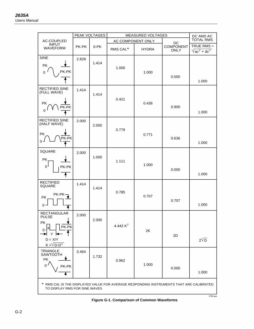
2635AUsers Manual
G-2
DC AND ACTOTAL RMS
TRUE RMS =
0.0001.000
1.000
0.900
0.636
0.000
0.707
1.000
1.000
1.000
2D
0.0001.000
AC-COUPLEDINPUT
WAVEFORM PK-PK
PEAK VOLTAGES
0-PK
MEASURED VOLTAGES
AC COMPONENT ONLY
RMS CAL* HYDRA
DCCOMPONENT
ONLY
SINE
PK
0 PK-PK
2.8281.414
1.0001.000
0.4360.421
1.414
2.0000.779
0.771
1.414
2.000
2.000
1.414
2.000
1.000
1.414
1.111
0.785
1.000
0.707
3.464
2.000
1.732
4.442 K
0.962
2K
1.000
PK-PK
PK-PK
PK-PK
PK-PK
PK-PK
2
0
PK
RECTIFIED SINE(FULL WAVE)
RECTIFIED SINE(HALF WAVE)
0
PK
0
PK
SQUARE
PK-PK
0
PK
RECTIFIEDSQUARE
RECTANGULARPULSE
0
PK
X
Y
D = X/Y
K = D-D2
TRIANGLESAWTOOTH
0
PK
ac + dc2 2
* RMS CAL IS THE DISPLAYED VALUE FOR AVERAGE RESPONDING INSTRUMENTS THAT ARE CALIBRATED TO DISPLAY RMS FOR SINE WAVES
2 D
078f.eps
Figure G-1. Comparison of Common Waveforms
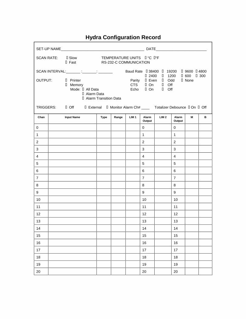
Hydra Configuration Record
SET-UP NAME_________________________________________ DATE_________________________
SCAN RATE: q Slow TEMPERATURE UNITS q °C q°Fq Fast RS-232-C COMMUNICATION
SCAN INTERVAL:_______ :_______: _______ Baud Rate q 38400 q 19200 q 9600 q 4800q 2400 q 1200 q 600 q 300
OUTPUT: q Printer Parity q Even q Odd q Noneq Memory CTS q On q Off Mode: q All Data Echo q On q Off
q Alarm Dataq Alarm Transition Data
TRIGGERS: q Off q External q Monitor Alarm Ch# ____ Totalizer Debounce q On q Off
Chan Input Name Type Range LIM 1 AlarmOutput
LIM 2 AlarmOutput
M B
0 0 0
1 1 1
2 2 2
3 3 3
4 4 4
5 5 5
6 6 6
7 7 7
8 8 8
9 9 9
10 10 10
11 11 11
12 12 12
13 13 13
14 14 14
15 15 15
16 16 16
17 17 17
18 18 18
19 19 19
20 20 20

Hydra Memory Card Record
DATA FILES SET-UP FILES
DATxx Application Note SETxx Application Note

1
Index
—2—2-wire accuracy, A-8, A-12
—A—AC operation, 1-13Ac signal cross talk in a dc voltage channel, B-1Ac signal cross talk into a frequency
channel, B-3Ac signal cross talk into an ac voltage
channel, B-2Ac signal cross talk into an ohms channel, B-2Ac signal crosstalk into a temperature
channel, B-3AC Voltage Measurements, A-8accuracy verification test, 7-7adjusting the handle, 1-12Alarm indications while monitoring, 2-19Alarm indications while reviewing, 2-19Alarm indications while scanning, 2-18Alarm outputs, 1-17alarm outputs and digital I/O, 1-9alarm outputs connections, 1-17Alarm outputs for channel 0 to 3 using the alarm
outputs connector, 2-19Alarm outputs for channels 4 to 20 using the
digital I/O connector, 2-19alarms, 1-9Alarms and autoprinting, 2-20Alarms and monitor-alarm triggering, 2-20Alarms and Mx+B scaling, 2-20applications software, 1-9
—C—calibration, 7-21changing the memory card during scanning, 3-5
channel integrity test, 7-8cleaning, 7-3Clearing alarm parameters from a channel, 2-19Clearing Mx+B scaling from a channel, 2-23Common mode rejection, A-10computer interface command set, 4-18computer interface commands and
operation, 4-12computer operation, 1-8configuring a channel to measure ac volts, 2-10configuring a channel to measure dc volts, 2-9configuring a channel to measure frequency, 2-12configuring a channel to measure resistance, 2-11configuring a measurement channel, 2-8configuring for printer operations, 5-5configuring the instrument for computer
operations, 4-5configuring the instrument for modem
operations, 6-7configuring the instrument for operation, 2-6configuring the instrument modem for modem
operations, 6-4configuring the pc for computer operations, 4-6connecting the instrument to a pc, 4-3connecting the instrument to a power
source, 1-12connecting the instrument to a printer, 5-3connecting the modem to a pc for modem
configuration, 6-4connecting the modem to an instrument, 6-6connector set, 2620a-100, 1-10controls and indicators, 1-19crosstalk, 1-14Cross-talk rejection, A-8
—D—data file procedures, 3-12

2635AUsers Manual
2
DC operation, 1-13DC power, 1-17Decoding the ascii string, C-1dedicated alarm output test, 7-18Digital I/O, 1-18digital I/O connections, 1-18Digital input test, 7-16Digital output test, 7-15
—E—Example, C-7Examples, 2-23External trigger, 2-31External trigger input, 1-17external trigger input test, 7-21
—F—Floating point conversion, C-4four-terminal resistance test, 7-10front panel controls, 1-19front panel indicators, 1-19front panel operation, 1-7
—H—how the instrument processes input, 4-12how the instrument processes output, 4-13hydra logger package, 1-10hydra starter package, 1-10Hysteresis, A-14
—I—initializing a memory card, 3-7input channels, 1-13Input debouncing, A-14input string examples, 4-13input terminators, 4-12Input voltage, A-14inserting a memory card, 3-5inserting and removing the memory card, 3-5installing or replacing the memory card
battery, 3-5Instrument event register (IER), 4-14Isolation, A-14
—L—line fuse, 7-3
—M—Maximum autoranging time, A-14measurement capabilities, 1-9Memory card as a data destination, 2-26memory card battery, 3-5
memory card capacity, 3-4Memory card capacity, 2-26Memory card data extraction, 2-27Memory card exchange during scanning, 2-26memory card file operations to and
from a pc, 3-16Memory card files, 2-26Memory card formatting, 2-26memory card operation, 1-7memory card reader, 1-10modem operation, 1-8Monitor-alarm trigger, 2-31Mx+B scaling, 1-9
—O—open thermocouple response test, 7-11operating modes, 1-5, 2-26options and accessories, 1-10
—P—performance tests, 7-4printer operation, 1-8printing measurement data and memory card
directory, 5-6printing measurement results during
scanning, 5-6printing the directory of the memory card, 5-9printing the review array, 5-8
—R—Rate, A-14recording measurement results during
scanning,3-8removing a memory card, 3-5Resistance temperature detectors
restrictions:, 2-13Resistance-temperature detectors, 2-13Restrictions, 2-8, 2-9, 2-10, 2-11, 2-12, 2-23RTD temperature accuracy test, 7-13RTD temperature accuracy test (using decade
resistance source), 7-13RTD temperature accuracy test (using DIN/IEC
751 RTD), 7-14
—S—selecting a channel, 2-8selftest diagnostics and error codes, 7-4sending numeric values to the instrument, 4-13Sensitivity, A-12service, 7-22setting the memory card write-protect
feature, 3-5setting the Mx+B scaling, 2-23

Index (continued)
3
setting up the instrument, 1-11setup and data file current status, 3-15setup and data files directory, 3-14setup file procedures, 3-9Standard event status register (ESR), 4-16Status byte register (STB), 4-17status registers, 4-14summary of computer operations, 4-3summary of front panel operations, 2-5summary of memory card operations, 3-3summary of modem operations, 6-3summary of printer operations, 5-3
—T—testing the instrument/pc RS-232 interface, 4-6testing the RS-232 interface using gwbasic, 4-9testing the RS-232 interface using Qbasic, 4-10testing the RS-232 interface using terminal
emulation (generic), 4-7testing the RS-232 interface using terminal
emulation (windows), 4-6testing the RS-232/modem interface, 6-8thermocouple measurement range accuracy
test, 7-9Thermocouple restrictions:, 2-13thermocouple temperature accuracy test, 7-10Thermocouples, 2-13Threshold, A-14
totalizer channel, 1-9Totalizer input, 1-18Totalizer sensitivity test, 7-18Totalizer test, 7-17Totalizing input, A-14Triggering options and memory card
operation, 2-31turning the power on, 2-6
—U—universal input module connections, 1-14unpacking and inspecting the instrument, 1-11using data erase, 3-13using data open, 3-12using setup erase, 3-11using setup load, 3-10using setup store, 3-9using shielded wiring, 1-14using the scan mode, 2-26
—V—variations in the display, 7-22
—X—xmodem file transfers, 4-18

2635AUsers Manual
4