hybrid visible light communication for cameras and...
TRANSCRIPT

Hybrid Visible Light Communication for Cameras andLow-Power Embedded Devices
Niranjini Rajagopal Patrick Lazik Anthony RoweElectrical and Computer Engineering Department
Carnegie Mellon University{niranjir,plazik,agr}@ece.cmu.edu
ABSTRACTVisible light communication (VLC) between LED light bulbsand smart-phone cameras has already begun to gain trac-tion for identification and indoor localization applications.To support detection by cameras, the frequencies and datarates are typically limited to below 1kHz and tens of bytesper second (Bps). In this paper, we present a technique fortransmitting data from solid-state luminaries, used for inte-rior ambient lighting, simultaneously to both cameras andlow-power embedded devices in a manner that is impercep-tible to occupants. This allows the camera communicationVLC channel to also act as a higher speed downstream linkand low-power wakeup mechanism for energy-constraineddevices. Our approach uses Manchester encoding and Bi-nary Frequency Shift Keying (BFSK) to modulate the high-speed data stream and applies duty-cycle adjustment to gen-erate the slower camera communication signal. We explorethe trade-off between the performance of the two communi-cation channels. Our hybrid communication protocol is alsocompatible with existing IR receivers. This allows lights tocommunicate with low-cost commodity chipsets and controlhome appliances such as TVs, AV receivers, AC windowunits, etc. We show that we are able to reliably simultane-ously transmit low-speed data at 1.3 Bps to camera enableddevices and higher-speed data at 104 Bps to low-power em-bedded devices. Since the majority of energy in many RFcommunication protocols often goes towards media accessand receiving, VLC-triggered wakeup can significantly de-crease system energy consumption. We also demonstratea proof-of-concept wakeup circuit that consumes less then204uA and can be triggered in less then 10ms.
Categories and Subject Descriptors[Networks]: Wireless local area networks; [Networks]:Location based services; [Information systems]:
Permission to make digital or hard copies of all or part of this work for personal orclassroom use is granted without fee provided that copies are not made or distributedfor profit or commercial advantage and that copies bear this notice and the full cita-tion on the first page. Copyrights for components of this work owned by others thanACM must be honored. Abstracting with credit is permitted. To copy otherwise, or re-publish, to post on servers or to redistribute to lists, requires prior specific permissionand/or a fee. Request permissions from [email protected]’14, September 7, 2014, Maui, Hawaii, USA.Copyright 2014 ACM 978-1-4503-3067-1/14/09 ...$15.00.http://dx.doi.org/10.1145/2643164.2643173.
General TermsExperimentation, Measurement
KeywordsVisible light communication, Hybrid data-rate, Camera com-munication
1. INTRODUCTIONInside buildings, light bulbs are pervasive, have ample ac-
cess to power, and are often well positioned for sensing andcommunication applications. VLC holds the promise of pro-viding an extremely high data-rate and low-cost networklink. VLC systems have the potential for high signal-to-noise ratios (greater than 50dB), are not regulated by theFCC, and can be contained easily within walls, providinga high degree of spatial diversity. In most high-rate VLCsystems, the receiver is a device with a photodiode. An-other common receiver for VLC is the camera in a mobilephone. This is particularly useful in localization of mobilephones where the lights act as landmarks or anchor points[1]. If each light can uniquely identify itself to nearby mo-bile devices, it would be possible to easily distinguish be-tween rooms and areas within a room that are illuminatedby different lights. Combining communication with geomet-ric information such as the position of multiple lights inan image and angle-of-arrival, camera communication-basedlocalization systems have achieved sub-meter accuracy [2].Broadly, in the VLC space, we have high data-rate systemswith photodiode-based receivers and lower data-rate systemswith camera-based receivers.
In this paper, we investigate the problem of mixing cameracommunication with faster modulation designed for systemswith photodiode receivers. This would allow LED bulbs tocommunicate with off-the-shelf mobile devices while simulta-neously coordinating and acting as a downlink for ultra-lowpower tags and sensors.
Utilizing interior lights in this context for mixed commu-nication is challenging for four main reasons: First, the sys-tem should be dimmable and flicker-free in order to providehigh-quality indoor illumination. Second, since most smart-phones no longer have high-speed optical sensors (like IRreceivers), we would like to decode data using cameras thattypically only operate at tens of hertz, while interleaving thehigher-speed communication for low-power devices. Third,duty-cycled asynchronous low-power wakeup needs to coex-ist with the normal data streams. Finally, due to the dense

Radio
Modulator
LED Driver
LED
Demodulator
Camera
Data
Demodulator
Photo Receiver
Data RX
Radio TX
Low Power Wake-‐up
LED Bulb
Low-‐Power Sensor Node
Mobile Camera Device
AC Mains
60Hz
Sync
Figure 1: System architecture
configurations of indoor lighting, we require the ability tosupport scalable multiple-access among transmitters.
The main contribution of this paper is the design andevaluation of a protocol that communicates with low-powerembedded devices and cameras simultaneously in a scalablemanner for indoor applications.
2. SYSTEM ARCHITECTUREFigure 1 shows our envisioned system architecture. We
see LED lights that have a radio receiver and an onboardprocessor that is responsible for generating a modulated sig-nal. The lights also have access to a common global 60Hzsignal from the AC mains that can be used for time syn-chronization to help facilitate MAC coordination. Time syn-chronization can also be achieved using RF. Previous workshows how mobile devices like smart-phones can decode dataat a low rate using their onboard camera (briefly reviewedin the next section). Low-power sensor nodes can leveragea high-speed signal for ultra-low power wakeup as well asdownstream communication. All of the required hardwarefor the transmitters already exists in commercially avail-able LED retrofits like the Philips Hue, LIFX, TCP connect,etc. We believe our solution should be compatible througha firmware modification to many of these devices.
2.1 Communicating with Low-Power TagsWhen communicating with low-power embedded devices,
we are primarily concerned with two modes of operation:First, there should be a readily accessible data channel fordevices that wish to periodically wake up and check for con-trol commands such as clock synchronization. Second, thereshould be an ability to asynchronously wake up devices in or-der to perform low-latency queries such as requesting for thelast sampled sensor value. For example, in ultra-low powerenvironments like those found in energy harvesting systems,one of the main practical concerns is that devices may onlytransmit data at a period of tens of minutes or hours. Inmany applications (like querying for a location), we wouldlike to be able to immediately ping the device expendingsome of its energy budget when it is most valuable. Thistype of interaction can be enabled by an always-on VLCwakeup mechanism. We designed a proof-of-concept circuitthat consumes less then 204uW, but in a future revision thiscould be drastically decreased to below the drainage thresh-
old of batteries. Our current implementation also does notoperate over a wide dynamic range.
2.2 IR ReceiverThere has been extensive work on photodiode-based VLC
communication over the past few decades. Rather than in-venting an entirely new low-level modulation scheme, weadapt existing work from IR communication. There aremultiple common techniques used to transmit IR data thatrange in speed between 9.6kbps (SIR), all the way to 16Mbps(VFIR). We adopt an approach similar to the RC-5 stan-dard that uses bursts of a particular frequency (37.9kHz)to modulate Manchester encoded data. In order to controlthe intensity of the signal for the camera communication,we can adjust the duty-cycle of the carrier bursts and padnon-carrier times with a similarly duty-cycled out-of-bandfrequency. Since overhead LED lights are extremely power-ful compared to most IR LEDs in hand-held controllers, weare able to send IR data signals to existing appliances. Manyof the new LED bulbs already have RF capabilities, enablingthem to act as reliable proxies to replace older line-of-sightIR remotes.
3. RELATED WORKThere is a significant body of work for sending high-speed
data over light using specialized hardware. The favorablecharacteristics of using unlicensed spectrum at bandwidthsof up to 100MHz [3] with trichromatic (RGB) LEDs, or upto 20MHz with the more ubiquitous phosphorescent whiteLEDs [4, 5], make it an attractive contender for wirelesscommunication. In 2006, the IEEE developed a draft VLCstandard known as 802.15.7 [6]. All of these approaches usea variant of On-Off keying (OOK) for modulation. Morecomplex schemes such as Quadrature Amplitude Modula-tion (QAM) and Discrete Multi-tone Modulation (DMT) /Orthogonal Frequency Division Multiplexing (OFDM) [7]are also possible, but require analog control over the LEDintensity which increases hardware costs.
There have also been several efforts to use the rolling-shutter based smart-phone cameras as communication re-ceivers. Danakis et. al. [8] exploit the rolling shutter effectof a smart-phone’s CMOS camera to capture OOK modu-lated data from LEDs. The authors generate data sequencesusing Manchester encoding, resulting in multiple symbolsbeing captured per frame. VRCodes (NewsFlash) [9] takesadvantage of the rolling shutter effect to decode visual tagsdisplayed on LCDs. The technology exploits the ”flicker-fusion threshold”of the human eye to blend the tags into thebackground by rapidly flashing complimentary hues of color,still visible to a rolling shutter camera. CamCom [10] usesundersampled frequency shift OOK (UFSOOK) by encod-ing data at frequencies that are harmonics of the frame rate,and decoding data by processing the subsampled aliased fre-quencies. ByteLight [19] is a commercial effort for communi-cation between overhead LED lights and mobile phones, bypossibly exploiting the rolling shutter effect of the camera.In this paper, we will be adopting a rolling-shutter basedBFSK camera communication method [1].
We believe that most the rolling-shutter based approacheswould also be compatible with our hybrid approach of duty-cycle controlled high-frequency signals overlayed on top oflower rate communication schemes. In all cases, changingthe duty-cycle will impact light and dark region contrast,

f0 f1 f1
Data : 011 Pilot f1
Start fS
f0 f1 f0
Data : 010 Pilot f1
Start fS Light 1
Light 2
Figure 2: Camera communication modulation
(a) (b)
(c) (d)
Figure 3: Images as seen by a camera of a sur-face illuminated by an LED pulsing at (a) 1kHz (b)100kHz. Mixed low-speed and high-speed communi-cation with (c) 15-85% duty cycle (d) 40-60% duty-cycle
which will have some negative impact on performance. Themain goal in this paper is to evaluate that impact and showthat such an approach is feasible. To the best of our knowl-edge, we are one of the first to formally explore the topic ofmixing camera communication with an infrastructure thatcommunicates at higher speeds with low-power devices.
In [11] we see that it is possible to create a device-addressablelow-power wakeup circuit in custom silicon that consumesas little as 695pW of power. While a custom silicon de-sign probes many of the fundamental limits of low-powerwakeup, we provide a simpler mechanism using off-the-shelfdiscrete components as a simple proof of concept for batteryoperated devices like wireless sensor nodes.
4. COMMUNICATION SCHEMEIn this section, we present an overview of the camera com-
munication scheme, followed by our proposed scheme of mix-ing the high-rate data stream with the camera communica-tion data stream.
4.1 Camera CommunicationFigure 2 shows an outline of our approach, which uses Bi-
nary Frequency Shift Keying (BFSK) to modulate the sig-nal driving the light [1]. A preamble indicates the start ofeach data packet, followed by a pilot which is identical toa transmitter’s on symbol. The pilot allows the receiversto measure the noise floor of each transmission. Multipletransmitters co-exist by using Frequency Division MultipleAccess (FDMA), where each is allocated a unique frequencyfor transmitting its on symbol.
The receiver is a CMOS rolling shutter camera that cap-tures the signal either through direct LOS or reflected fromsurfaces. Rolling shutter sensors expose and read out indi-vidual rows of pixels in a pipelined fashion. As a result, anLED pulsing at a frequency produces a banded image, the
frequency of which is proportional to the frequency of theLED.
After a sequence of image frames are acquired, the spa-tial variation of the frequency components over the imagesis used to estimate the input frequency of the lights. Thedemodulation and decoding is performed in software to de-tect the received IDs. With a frame rate of 30 frames persecond, a symbol duration of 33ms, and a frame length 14bits, a byte of data takes 462ms to transmit. It is possible todecode the camera communication signal using a photodi-ode in the same manner. However, for a low-power tag, theenergy consumed by staying on and processing data for thisamount of time is not trivial. The limiting factor for the lowdata rate of the camera communication is the frame rate ofthe camera and the rolling shutter scan rate. The photodi-ode receiver need not be constrained by these timings. Thismotivates the need for a scheme which can simultaneouslycommunicate with phones and tags at two different datarates (two different channels) - but share the same physicalchannel.
4.2 Incorporating High-Rate DataWhen overlaying high-speed data, we assume an LED
driver that generates a binary output, which is most com-mon in low-cost LED bulbs. We use Manchester encodingwith BFSK modulation, where a burst of pulses of two dif-ferent frequencies represent the high and low logic levels ofthe encoded data.
Figure 3(a) and Figure 3(b) show simulated images ofwhat a camera would capture in the presence of a light puls-ing at 1kHz and 100kHz respectively. The column scan timeis 47us, which is approximately the same as a camera thatcaptures 1080p frames at 30fps (iPad 3). The image in Fig-ure 3(a) tends to look gray because the column scan timeis equivalent to 4.7 cycles of the 100kHz signal causing theaverage intensity of the light in this duration to be captureduniformly across the entire row. On the other hand, thebands are prominent in Figure 3(b) since every on or offperiod of the light at 1kHz spans across approximately 10columns of the image.
The frequency of the LED is determined by the high-speed data and the duty-cycle is determined by the low-speed data. When the high-speed modulated data overlapswith the on time of the light for the low-speed modulateddata, the pulses are duty-cycled such that the on time islonger than the off time. Similarly, when the high-speedmodulated data overlaps with the off time of the light forthe low-speed modulated data, the pulses are duty-cycledsuch that the off time is longer than the on time. This re-sults in light gray and dark gray stripes instead of white andblack stripes on the images.
Figure 3(c) and Figure 3(d) show images that we wouldexpect to see by varying the duty cycle of the 100kHz sig-nal based on overlapping the 1kHz signal of the low-speedcommunication. Figure 3(a) is equivalent to the mixed com-munication system with 50-50% duty cycle and Figure 3(b)is equivalent to the mixed communication system with 0-100% duty cycle. Figure 4 shows a snapshot of the pro-posed modulation scheme. The top row shows the BFSKmodulated low speed data as proposed in our previous work[1]. The second row shows the Manchester encoded highspeed data. The third row shows the modulated data wherethe frequency is determined by the high-speed encoded data

0
0.5
1
Low frequency signal
−3
−2
−1
0
1
Bit 1
Freq 2 Freq 1
Bit 0
Freq 1 Freq 2
Bit 1
Freq 2 Freq 1
Bit 0
Freq 1 Freq 2
Bit 0
Freq 1 Freq 2
Bit 1
Freq 2 Freq 1
Manchester encoded High Frequency data symbols
1000 2000 3000 4000 5000 6000 7000
0
0.5
1
Freqeuncy modulated High Frequency data duty−cycled as per low frequency signal
Time (us)
Image as seen by rolling shutter sensor
Figure 4: Mixed low-speed and high-speed communication
and the duty-cycle is determined by the low-speed data. Thebottom row shows the resulting image from the camera.
The receiver for the low-speed data can be any smart-phone with a rolling-shutter based camera. To receive thehigh-speed data, we can use a photodiode and demodulatethe BFSK data either by analog frequency detection (oftenperformed in hardware) or performing the frequency analysisafter acquiring the data. The thresholded signal is thendecoded by a Manchester decoder. We propose using anIR Receiver Module (for example a RPM7138-R) for thereceiver. This is commonly used for remote controls and hasa reasonably low current consumption of 0.95mA. This chipis designed for an IR transmitter at 37.9kHz. In our scheme,we use a burst of pulses of frequency 37.9Hz and an out-of-band frequency (10kHz) for modulating the Manchesterencoded data to avoid flicker. This results in a high-speeddata rate of 104Bps. The limiting factor with respect to datarate is the IR receiver, however, other receivers can operateat higher rates.
4.3 Multiple AccessThe camera communication uses assigned frequencies to
support multiple transmitters within a single collision do-main through FDMA. Since the embedded tags are not ableto simultaneously decode multiple frequencies, we suggestusing a Time Division Multiple Access (TDMA) scheme toseparate transmissions in time. Though not the focus of thiswork, TDMA time slots can be picked based on the FDMAfrequencies used by each light.
5. LOW-POWER WAKEUPOur low-power wakeup circuit is activated by receiving an
unmodulated 100 kHz signal, broadcast from a VLC trans-mitter. A photodiode captures all incoming light, which ispassed through multiple high-pass filters. The filters atten-uate any out-of-band data signals and trigger a low-power
10k
PDB-‐C156
7.5k
MAX9915
-‐ +
1M
1M
1.6k
7.5k
-‐ +
1M
1.6k
MAX9915 2M
-‐ +
274k
1n
1M 1.8V
1.8V
1.8V
1n 1n
1.8V
1.8V 1.8V
Output
MCP6546
1.8V
Figure 5: Proof-of-concept wakeup circuit
comparator if a wakeup signal is received. The compara-tor digitizes the received signal, which may then be usedto wake an attached microcontroller. Due to the limitedbandwidth-gain-product of the op-amps in the filters, thecircuit uses two cascaded op-amps to provide a relatively flatfrequency-response and hence equal amplification to morethan 100kHz.
The circuit consumes approximately 204µA at 1.8V whenactive and may be further duty-cycled to reduce power. Thethreshold on the comparator is tunable to allow for differ-ent light intensities. Though functional, this circuit exhibitsrelatively poor dynamic range. We intend to refine and fur-ther evaluate how to build efficient wakeup circuits, but thisdesign confirms feasibility.

VLC LED Bulb
Low-‐Power Wakeup Circuit Rear iPad Camera
Logic Analyzer
Figure 6: Experimental setup
6. EVALUATIONOur experimental setup is shown in Figure 6. We based
our prototype light on a 9.5 Watt (60W incandescent equiv-alent) Cree warm white (2700K) LED bulb, which outputs800 lumens and is currently available for less than $9. Wereplaced the bulb’s power electronics with a simple MOS-FET driver circuit, which is controlled by a function gen-erator sending it synthesized signals. We use an adjustableaperture over the light for controlling the illumination. Thereceiver for the high-speed data is a standard infrared re-ceiver module, commonly used in remote control receivers(ROHM RPM7138-R), connected to a logic analyzer. Weuse the front-facing camera on an iPad 3 collecting 720pHD video at 30fps as a receiver for the low-speed data. Itis mounted 5cm above a white surface. We generate thesignals in MATLAB and transmit it to the LED using aprogrammable signal generator. Captured images are thensent back to MATLAB for processing.
6.1 Base-Line Performance Variation With Il-lumination
With high speed data modulated at around 40kHz andsupport for low duty-cycle (10%), a sampling frequency ofat least 400kHz is required. A symbol length of 33ms (oneframe at 30fps) for the camera communication restricted thedata to an equivalent of three symbols of low-speed data dueto the limited buffer size in our function generator. Sincethis was insufficient to send a full length data sequence,we first obtained the BER-SNR mapping (Figure 7(a)) forthe camera communication without the high-speed data bytransmitting 25 random packets consisting of 6 bits of lowspeed data. For all further tests with high-speed data, wetransmit 25 random packets consisting of 16 bits of highspeed data and 3 symbols of low speed data. In these tests,we evaluate the BER of high speed data and SNR of thecamera communication.
Figure 7(b) shows the performance of both channels at20% duty cycle over a range of transmission luminosities. Inour experiment the system was able to decode data correctlydown to a transmission illumination of 220lux, after whichthe BER increases rapidly. The SNR of the low-speed signalincreases exponentially over the measured illuminations.
0 20 40 60 80 100 1200
0.05
0.1
0.15
0.2
0.25
0.3
0.35
0.4
0.45
SNR of Camera Communication
BE
R o
f C
am
era
Co
mm
un
ica
tio
n
(a)
0 200 400 600 800 1000 12000
0.1
0.2
BE
R o
f H
igh S
peed D
ata
Illumination (lux)
Performance at 20% duty cycle
0 200 400 600 800 1000 12000
50
SN
R o
f Low
Speed D
ata
(b)
Figure 7: (a) BER to SNR mapping for camera (b)Performance of both channels with change in illumi-nation
6.2 Trade-Off Between High and Low-Rate Com-munication
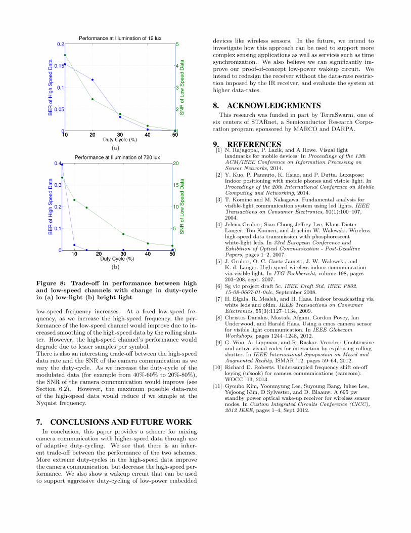
Figure 8(a) shows the impact of the high-speed data duty-cycle on both communication channels at 12lux of luminos-ity, measured by a light meter on the white surface in thefield of view of the iPad’s camera. We see an inverse rela-tionship between the duty-cycle of the high-speed data andthe BER, as well as an inverse relationship with the SNRof the low-speed component. This is to be expected sincethe high-speed component reduces the contrast of low-speeddata. Figure 8(b) shows the same experiment at an illumi-nation of 720lux. With more light, we see that the BER ofthe high-speed data is vastly reduced due to the increase intransmission power and the SNR of the low-speed compo-nent is approximately doubled for each duty-cycle setting.The illumination value of this setup corresponds to what canbe expected in a normal office environment.
6.3 Future EvaluationThere are a few more trade-offs that we would like to eval-
uate in the future, which are currently not possible since ourIR receiver fixes the modulation frequency to 37.9kHz (seeSection 2.1).There is a trade-off between the performance of both com-munication systems as the ratio of high-speed frequency to
10 20 30 40 500
0.05
0.1
0.15
0.2B
ER
of H
igh S
peed D
ata
Duty Cycle (%)
Performance at Illumination of 12 lux
10 20 30 40 501
2
3
4
5
SN
R o
f Low
Speed D
ata
(a)
10 20 30 40 500
0.1
0.2
0.3
0.4
BE
R o
f H
igh S
peed D
ata
Duty Cycle (%)
Performance at Illumination of 720 lux
10 20 30 40 500
5
10
15
20
SN
R o
f Low
Speed D
ata
(b)
Figure 8: Trade-off in performance between highand low-speed channels with change in duty-cyclein (a) low-light (b) bright light
low-speed frequency increases. At a fixed low-speed fre-quency, as we increase the high-speed frequency, the per-formance of the low-speed channel would improve due to in-creased smoothing of the high-speed data by the rolling shut-ter. However, the high-speed channel’s performance woulddegrade due to lesser samples per symbol.There is also an interesting trade-off between the high-speeddata rate and the SNR of the camera communication as wevary the duty-cycle. As we increase the duty-cycle of themodulated data (for example from 40%-60% to 20%-80%),the SNR of the camera communication would improve (seeSection 6.2). However, the maximum possible data-rateof the high-speed data would reduce if we sample at theNyquist frequency.
7. CONCLUSIONS AND FUTURE WORKIn conclusion, this paper provides a scheme for mixing
camera communication with higher-speed data through useof adaptive duty-cycling. We see that there is an inher-ent trade-off between the performance of the two schemes.More extreme duty-cycles in the high-speed data improvethe camera communication, but decrease the high-speed per-formance. We also show a wakeup circuit that can be usedto support aggressive duty-cycling of low-power embedded
devices like wireless sensors. In the future, we intend toinvestigate how this approach can be used to support morecomplex sensing applications as well as services such as timesynchronization. We also believe we can significantly im-prove our proof-of-concept low-power wakeup circuit. Weintend to redesign the receiver without the data-rate restric-tion imposed by the IR receiver, and evaluate the system athigher data-rates.
8. ACKNOWLEDGEMENTSThis research was funded in part by TerraSwarm, one of
six centers of STARnet, a Semiconductor Research Corpo-ration program sponsored by MARCO and DARPA.
9. REFERENCES[1] N. Rajagopal, P. Lazik, and A Rowe. Visual light
landmarks for mobile devices. In Proceedings of the 13thACM/IEEE Conference on Information Processing onSensor Networks, 2014.
[2] Y. Kuo, P. Pannuto, K. Hsiao, and P. Dutta. Luxapose:Indoor positioning with mobile phones and visible light. InProceedings of the 20th International Conference on MobileComputing and Networking, 2014.
[3] T. Komine and M. Nakagawa. Fundamental analysis forvisible-light communication system using led lights. IEEETransactions on Consumer Electronics, 50(1):100–107,2004.
[4] Jelena Grubor, Sian Chong Jeffrey Lee, Klaus-DieterLanger, Ton Koonen, and Joachim W. Walewski. Wirelesshigh-speed data transmission with phosphorescentwhite-light leds. In 33rd European Conference andExhibition of Optical Communication - Post-DeadlinePapers, pages 1–2, 2007.
[5] J. Grubor, O. C. Gaete Jamett, J. W. Walewski, andK. d. Langer. High-speed wireless indoor communicationvia visible light. In ITG Fachbericht, volume 198, pages203–208, sept. 2007.
[6] Sg vlc project draft 5c. IEEE Draft Std. IEEE P802.15-08-0667-01-0vlc, September 2008.
[7] H. Elgala, R. Mesleh, and H. Haas. Indoor broadcasting viawhite leds and ofdm. IEEE Transactions on ConsumerElectronics, 55(3):1127–1134, 2009.
[8] Christos Danakis, Mostafa Afgani, Gordon Povey, IanUnderwood, and Harald Haas. Using a cmos camera sensorfor visible light communication. In IEEE GlobecomWorkshops, pages 1244–1248, 2012.
[9] G. Woo, A. Lippman, and R. Raskar. Vrcodes: Unobtrusiveand active visual codes for interaction by exploiting rollingshutter. In IEEE International Symposium on Mixed andAugmented Reality, ISMAR ’12, pages 59–64, 2012.
[10] Richard D. Roberts. Undersampled frequency shift on-offkeying (ufsook) for camera communications (camcom).WOCC ’13, 2013.
[11] Gyouho Kim, Yoonmyung Lee, Suyoung Bang, Inhee Lee,Yejoong Kim, D Sylvester, and D. Blaauw. A 695 pwstandby power optical wake-up receiver for wireless sensornodes. In Custom Integrated Circuits Conference (CICC),2012 IEEE, pages 1–4, Sept 2012.