hybrid ethernet/sdh transport networks - bme-hitjakab/edu/litr/ng_sdh/multiservice_lucent.pdf ·...
TRANSCRIPT
A solution for service providers to leverage their installedbased of SDH equipment to build service-rich networks
Hybrid Ethernet/SDHTransport Networks
This white paper addresses:• Incorporating next generation services in a multiservice environment
• Achieving network convergence
• Building a converged metro network architecture
• Supporting network convergence with Lucent Technologies platforms
A multiservice solution forIP/Ethernet Transport Services

2
Abstract .............................................................................................3
Introduction .......................................................................................3
Service Convergence; Drivers for Hybrid Transport ....................................3
Hybrid Ethernet Transport Services......................................................4
Inter-POP Connections................................................................................4
Corporate LAN Interconnections ................................................................6
Managed IP services (i.e. IP-VPN, Internet Access, Hosting, VoIP etc.).......7
Lucent Technologies Ethernet Solutions ..............................................9
Lucent Technologies Solutions ..........................................................10
Lucent Technologies Service Intelligent™ Architecture............................10
SDH-based Solutions for Managed IP Services .........................................11
Lucent Metro Network Solutions for Corporate LAN Interconnects ........12
Lucent Metro-Core Network Solutions for ISP Inter-office Connections .14
Lucent Backbone Network Solutions for ISP Inter-office Connections.....15
Operations .................................................................................................16
Conclusion .......................................................................................18
Appendix A: Ethernet Transport-Enabling Technologies.....................19
Synchronous Digital Hierarchy (SDH) and Ethernet Transport ................19
Virtual Concatenation ...............................................................................19
LCAS and Data optimized protection options ...........................................19
Transporting packets in circuits .................................................................20
Wavelength Division Multiplexing (WDM) and Ethernet Transport ........20
Dedicated Optical Channel ........................................................................20
Shared Optical Channel.............................................................................21
10 GbE Clients on OLS ..............................................................................21
Authors ............................................................................................22
Dirk C L M van Bree..................................................................................22
Stéphan Roullot.........................................................................................22
Appendix B: Glossary........................................................................23
Table of Contents
3
Abstract
The next generation of Lucent Technologies transport solutions for access,metro, and backbone networks offer a full, multiservice portfolio. Theycan allow circuit or voice transport to be freely mixed with flexible datatransport. These types of networks are easier and less expensive tomanage than alternative solutions, such as separate fiber networks usingdifferent pieces of equipment in the access and metro networks.Furthermore, these solutions can facilitate a smooth migration to futureconverged networks; they are designed to maintain the advantages andinvestments in today’s circuit networks, while allowing for moreadvanced data services.
To accommodate the demand for these data services, equipment vendorsare incorporating Ethernet technology into transport network systems.Ethernet is the enterprise network standard, and when added to atransport network, it allows for flexible and high-capacity bandwidthservices that are easy to provision and maintain.
Almost all IP equipment has low-cost Ethernet interfaces. Therefore,Ethernet interfaces help provide a cost savings to the service provider andthe end-user. The service provider may also benefit from Ethernetinterfaces because Ethernet transport provides bandwidth flexibility andservice differentiation allowing them to introduce new Ethernet services.Ethernet packets can be transported in numerous ways. For example,Lucent Technologies implements various standards, such as virtualconcatenation and Link Capacity Adjustment Scheme (LCAS), in a broadrange of products for different types of services and different types ofnetwork architectures. These products help form solutions with thereliability, interoperability, and manageability that can typically only befound in today’s voice networks.
Introduction
Service Convergence; Drivers for Hybrid Transport
Telecommunications service providers are moving toward a newgeneration of packet-based optical networks. Because of the constantlyaccelerating demand for bandwidth, connectivity, and new applications —broadband data services have become a major part of the networkingbusiness. As new packet-based optical networks are built, and services suchas voice, video, and guaranteed performance Virtual Private Networks(VPNs) move onto these networks, a grand service convergence can occur.
The increased multiservice nature of converged networks requiresefficient handling of voice and data, wideband and broadband, electricaland optical interfaces. Furthermore, an enduring network infrastructuremust offer affordable evolution despite unpredictable demand growth. Tosupport the convergence, one can switch to totally data (Ethernet)oriented networks, where each network element does packet switching.However, pure data (Ethernet) networks are typically not as robust inavailability, reliability, pro-active and active maintenance, scalability andtransparency. The other option is to extend the current transport networkarchitecture into a new generation transport architecture optimized forboth circuit transport and data traffic growth.
“To accommodate thedemand for these dataservices, more and moreequipment vendors areincorporating Ethernettechnology intotransport networksystems.”

4
Ethernet has become the dominant technology for enterprise networkingin LANs. In data centers and ISP offices, the application of Ethernet isincreasing. Ethernet today is the most simple and low cost technology forshort distance data connections. Compared to the Packet over SDH (POS)router interfaces, Ethernet interfaces are generally priced much lower.Also, when we examine how LANs are interconnected via the publictransport network, the required POS long distance router interfaces arepriced higher than Ethernet interfaces.
Networks built on SDH and WDM are ideal for offering reliable, cost-effective transport for voice and private line services – services thatcontinue to dominate access network revenues today. However, pure SDHand WDM networks are not optimal for all services. For example, existingcircuit solutions do not have the bandwidth scalability and granularitythat high-speed data connections require. These shortcomings related todata transport are addressed with the next generation transport networks.
One of the next generation network components is the integration ofEthernet technology. Support for standard Ethernet interfaces directly onnetwork elements, such as SDH Add/Drop Multiplexers (ADM) andDWDM Optical Line Systems (OLS), will offer the required optimizationsfor data services. This solution helps to enable low-cost datainterconnectivity with customer and ISP equipment while maintainingthe reliable and manageable data transport that is required in largenetworks. It allows Service Providers with large embedded SDH networksto leverage their investment in staff, operational practices, managementsystems and equipment to provide new Ethernet Services quickly fromany location in the network at marginal cost. Lucent Technologies refersto this concept as “hybrid transport.”
There are a number of new services that can enhance the operator’srevenue and are made possible by the hybrid transport technology. TheseEthernet services and the Ethernet solutions that Lucent Technologies canoffer are presented in this white paper.
Hybrid Ethernet Transport Services
Lucent Technologies has identified three major Hybrid Ethernet transportservices:
• Inter-POP services
• Corporate LAN interconnect services
• Managed IP services (i.e. IP-VPN, Internet Access, Hosting, VoIP etc.)
Each service has its own network requirement and therefore leads todifferent network architectures.
Inter-POP Connections
ISPs need flexible, high-bandwidth connections between their IP routersand their bandwidth wholesaler. The bandwidth demands could beanywhere between 100Mbps and 1Gbps. Inside a Point of Presence (intra-POP), the router connections are increasingly made by high speedEthernet links. For connections between routers on different locations(inter-POP), a wide range of technologies is used. Some of these router

5
interfaces like POS are expensive compared to Ethernet interfaces, drivingcosts up for both service providers and their customers.
Direct paths between the main routing locations in the form of dedicatedSDH or WDM signals are more effective than networks where routing isperformed at each and every node. If a router (or Ethernet switch) is usedat an intermediate node, most data traffic that flows from the transportlayer towards the router will return immediately to follow its way in thetransport layer (pass-through traffic). In other words, in an intermediatenode it is inefficient and expensive to add routing functionality.Furthermore, the amount of electronics needed in a router is much higherfor comparable switching capacity. In particular, for high-speedconnections where the components work near the limits of electronicprocessing, routing comes at a premium.
Hybrid Transport based on SDH can provide high-speed and simple leasedline Ethernet connections over large distances (see Figure 1). These point-to-point services are flexible in bandwidth by the use of virtualconcatenation and LCAS1. Ethernet interfaces support frame transfer ratesof 0bit/s up to their designated interface rate of 100Mbps or 1Gbps. Thiscombination allows for the provisioning of a wide range of bandwidth. Acustomer can slowly increase the bandwidth of its service connection, orcan change the bandwidth frequently, depending on demand. Thesechanges are quickly done through provisioning, without the need tochange or update equipment.
Figure 1: High-speed point-to-point Ethernet services as inter-POP connections
Another option is to transport Gigabit Ethernet (GbE) with hybridtransport based on WDM solutions. When the full bandwidth of a 10GbEservice is needed, it is transported best with WDM technology, or whenenough fibers are available, directly on a fiber.
As with the lower-rate Ethernet interfaces, it is also possible to use a10GbE interface while only a part of the bandwidth is available in theSDH transport layer. This gives more bandwidth flexibility between 1GbEand 10GbE. It should become more economical when the prices of 10GbEinterfaces have dropped considerably, and the line rate of SDH systemshas increased to 40Gbps.
RoutersPoint-to
-point
Service
Connection
Transport N
etwork
(SDH and/or WDM)
MUX
MUX
MUX
Routers
Routers
Ethernet (physical)Service Connection (logical)Service Connection (logical)
1 See Appendix A for an explanation of virtual concatenation and LCAS.
6
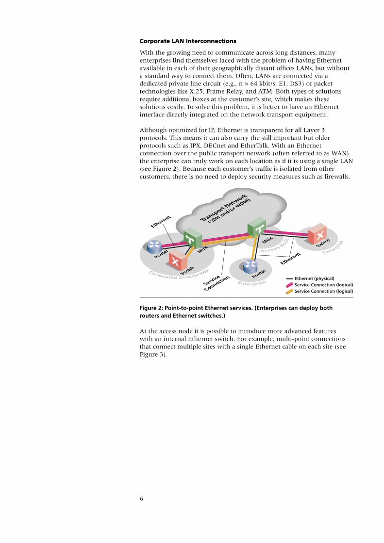
Corporate LAN Interconnections
With the growing need to communicate across long distances, manyenterprises find themselves faced with the problem of having Ethernetavailable in each of their geographically distant offices LANs, but withouta standard way to connect them. Often, LANs are connected via adedicated private line circuit (e.g., n × 64 kbit/s, E1, DS3) or packettechnologies like X.25, Frame Relay, and ATM. Both types of solutionsrequire additional boxes at the customer’s site, which makes thesesolutions costly. To solve this problem, it is better to have an Ethernetinterface directly integrated on the network transport equipment.
Although optimized for IP, Ethernet is transparent for all Layer 3protocols. This means it can also carry the still important but olderprotocols such as IPX, DECnet and EtherTalk. With an Ethernetconnection over the public transport network (often referred to as WAN)the enterprise can truly work on each location as if it is using a single LAN(see Figure 2). Because each customer’s traffic is isolated from othercustomers, there is no need to deploy security measures such as firewalls.
Figure 2: Point-to-point Ethernet services. (Enterprises can deploy bothrouters and Ethernet switches.)
At the access node it is possible to introduce more advanced features with an internal Ethernet switch. For example, multi-point connectionsthat connect multiple sites with a single Ethernet cable on each site (seeFigure 3).
Transport N
etwork
(SDH and/or WDM)
Router
RouterSwitch
MUXMUX
Ethernet
Ethernet (physical)Service Connection (logical)Service Connection (logical)
Switch
Service
Connection
Ethernet

7
Figure 3: Multi-point Ethernet services and ISP access services
To allow a gradual increase of bandwidth usage from an enterprisecustomer, the bandwidth used in the SDH transport network is scaledwith virtual concatenation (same as for inter-POP connections). This helpsmeet today’s requirement of 2Mbps up to 1000Mbps. Anotheropportunity in the Ethernet service market is the area of service ratesbelow 2Mbps and the area of bandwidth sharing. These connections canbe aggregated/shared with statistical multiplexing to help provide cost-effective, access services with throughput rates of 150Kbps up to the full1Gbps. Customer isolation is maintained with a user-tagging scheme,based on standard simple IEEE802.1Q or double-VLAN tagging scheme.
Very bandwidth hungry enterprises can be served with 1GbE interfaces.The requirements and solutions are similar to ISP inter-POP services inthe previous section.
Managed IP services (i.e. IP-VPN, Internet Access, Hosting, VoIP etc.)
An ISP office has connections to many customers. When this isimplemented with a point-to-point connection for each customer, manycable connections are required between the SDH multiplexer(s) at the ISPoffice and the ISP’s router(s). To limit the number of cables and ports onthe router, it is necessary to aggregate the data traffic from customersbefore that traffic is handed off to the router (see Figure 4). Routers cantypically only deal with statistically multiplexed data. Therefore, anEthernet switch is needed inside the SDH multiplexer to aggregate thedifferent data streams into a single, statistically-multiplexed Ethernetstream for the router.
The result is that only a single Ethernet link is needed to connect the ISProuter to the transport network, which is called a “VLAN trunk”. A VLANtrunk lowers the number of interfaces on the router and SDH multiplexer.Furthermore, the reduced amount of cabling helps save installation andmaintenance costs.
Transport N
etwork
(SDH)
Router
Switch
Switch
MUX
MUX
MUX
MUX
Routers
Ethernet
Ethernet
Ethernet
Ethernet (physical)Service Connection (logical)

8
VLAN tagging, a standard way to mark Ethernet packets, is used toidentify each customer’s packet stream on the VLAN trunk. With VLANtagging, strict security is maintained without the need for encryption.Conceptually this approach is identical to FR and ATM and offers thesame statistical multiplexing advantage, but with higher speeds at lowercosts without the need for separate, dedicated FR/ATM equipment.
Figure 4: Managed IP services
Relevant bit rates for Enterprise Internet access services are up to 10Mbpsat the enterprise access, with a 100Mbps VLAN trunk at the ISP, or acombination of services between 10Mbps and 100Mbps at the enterpriseaccess, with a 1Gbps VLAN trunk at the ISP.
The advantage of using an SDH network is that regular services, such asE1 for voice telephony, can be transported over the same network. This isvery useful for enterprises that want to keep their traditional PBX fortelephony, and at the same time grow their data connections. Anothermarket where the combination makes a perfect match is the xDSLnetwork business. The current DSLAMs typically can be equipped with100MbE or 1GbE data interfaces that need to be connected to the ISPoffice.
When an SDH network does not have enough capacity for a Metroregion, Passive WDM (PWDM) is an option that can be weighed againstnew fiber installation. PWDM technology chooses lower-cost WDMtechnology over more expensive and more capable DWDM technology.PWDM makes it possible to cope with fiber scarceness in metro regions.
Transport
Network
(SDH)
Router
Router
MUX
MUX
MUX
RoutersEthernet
Ethernet (physical)Service Connection (logical)Service Connection (logical)Service Connection (logical)
VLAN Trunk,
A Single
Ethernet Link
Ethernet

9
Lucent Technologies Ethernet Solutions
Lucent Technologies acknowledged the importance of Ethernet support atan early point in time. As a result, the ability to efficiently transportEthernet-based clients is widely implemented in the Lucent Technologiesoptical networking portfolio.
When equipped with WaveStar® TransLAN™ Cards, Lucent TechnologiesSDH multiplexers can offer transport of both IP data and voice over SDH.In addition, the core networking products that Lucent offers are designedto efficiently support Gigabit Ethernet and 10 Gigabit Ethernet interfaceson DWDM systems.
This portfolio-wide implementation helps provide cost-effective solutionsfor a broad variety of applications and network segments. With the rapidgrowth of demand for (gigabit) Ethernet services, Lucent TechnologiesEthernet solutions form a sound starting point to helping build acompetitive edge in this promising market.
Together with the suite of management software and the field proventrack record of network deployment around the globe, LucentTechnologies offers:
• tailored and cost-effective transport solutions for multiservice networks
• highly-efficient Ethernet transport capabilities
• efficient and integrated network operations
• professional network deployment

10
Lucent Technologies Solutions
Lucent Technologies offers solutions for the hybrid transport services thatwere defined in the previous sections. This section elaborates on howthese solutions and services work with available Lucent Technologiesproducts.
Table 1 provides an overview of the services and in which networksegment they will most likely be used. Three areas are identified: theAccess part of Metro networks; the Inter-Office part of the Metro network(IOF); and the Backbone. The lower portion of the table shows whichproducts can be used to provide Ethernet services for a certain networksegment.
Table 1: Relation between services, their network segments and suitableproducts.
The Managed IP Services and Corporate LAN interconnection services arenot noted in the backbone column. These services are certainly capable ofusing the transport facilities of the backbone network, however, no specialbackbone equipment is needed for these services.
The following sections illustrate solutions in more detail. (These solutionsare encircled in Table 1.)
Lucent Technologies Service Intelligent™ Architecture
Lucent’s unique vision for Service Intelligent™ Architecture helps serviceproviders optimize existing networks by reusing their embeddedinfrastructure and selectively adding systems when and where they’reneeded to offer new services. This approach helps generate profitable,new revenues in a measured fashion. At the same time, it helps lowercapital and operational expenses and simplifies network operations.
While Lucent’s vision of Service Intelligent™ Architecture is one of anintegrated, flexible, service-rich network, it is also a deployable strategyfor carriers to manage and evolve their networks, in order to flexibly andprofitably deliver new services. It is a holistic approach that encompassesa service provider’s entire network and focuses on the key elementsessential for intelligent network planning and management.
Metro-Access Metro-IOF Backbone
X X X
X X
X X
WaveStar®AM 1 PlusWaveStar® ADM 16/1WaveStar®ADM 16/1
Compact
WaveStar® TDM10GLambdaUniteTM MSS
Metropolis® EON
WaveStar® TDM10GLambdaUniteTM MSS
LambdaXtremeTM
Transport
Network Segment:
Services:
Inter POP Connections
Internet Access
Corporate LAN Interconnection
Products:
11
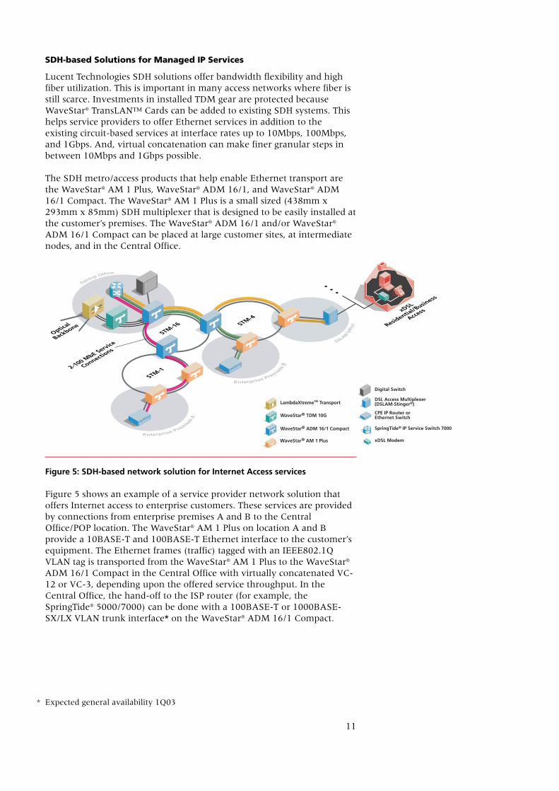
SDH-based Solutions for Managed IP Services
Lucent Technologies SDH solutions offer bandwidth flexibility and highfiber utilization. This is important in many access networks where fiber isstill scarce. Investments in installed TDM gear are protected becauseWaveStar® TransLAN™ Cards can be added to existing SDH systems. Thishelps service providers to offer Ethernet services in addition to theexisting circuit-based services at interface rates up to 10Mbps, 100Mbps,and 1Gbps. And, virtual concatenation can make finer granular steps inbetween 10Mbps and 1Gbps possible.
The SDH metro/access products that help enable Ethernet transport arethe WaveStar® AM 1 Plus, WaveStar® ADM 16/1, and WaveStar® ADM16/1 Compact. The WaveStar® AM 1 Plus is a small sized (438mm x293mm x 85mm) SDH multiplexer that is designed to be easily installed atthe customer’s premises. The WaveStar® ADM 16/1 and/or WaveStar®
ADM 16/1 Compact can be placed at large customer sites, at intermediatenodes, and in the Central Office.
Figure 5: SDH-based network solution for Internet Access services
Figure 5 shows an example of a service provider network solution thatoffers Internet access to enterprise customers. These services are providedby connections from enterprise premises A and B to the CentralOffice/POP location. The WaveStar® AM 1 Plus on location A and Bprovide a 10BASE-T and 100BASE-T Ethernet interface to the customer’sequipment. The Ethernet frames (traffic) tagged with an IEEE802.1QVLAN tag is transported from the WaveStar® AM 1 Plus to the WaveStar®
ADM 16/1 Compact in the Central Office with virtually concatenated VC-12 or VC-3, depending upon the offered service throughput. In theCentral Office, the hand-off to the ISP router (for example, theSpringTide® 5000/7000) can be done with a 100BASE-T or 1000BASE-SX/LX VLAN trunk interface* on the WaveStar® ADM 16/1 Compact.
DSLAM
Office
Optical
Backbone Residentia
l/Busin
ess
Access
STM-16
STM-1
STM-4
WaveStar® ADM 16/1 Compact
Digital Switch
LambdaXtremeTM Transport
WaveStar® AM 1 Plus
WaveStar® TDM 10G
SpringTide® IP Service Switch 7000
xDSL Modem
CPE IP Router orEthernet Switch
DSL Access Multiplexer(DSLAM-Stinger®)
2-100 MbE Service
Connections
xDSL
* Expected general availability 1Q03

12
The IEEE802.1Q VLAN trunk interface on the WaveStar® ADM 16/1Compact aggregates the data streams from multiple customers into onefully utilized 100bit/s or 1Gbps* data stream. Statistically, multiplexingcan be applied either in a central located WaveStar® ADM16/1 Compact orcan be done in any of the intermediate nodes. This leads to a morebandwidth-efficient Ethernet transport in the Virtual Concatenated VC12or VC3 signals that are connecting these central and intermediate nodestogether.
Figure 5 shows how the DSLAM Office can be equipped with a WaveStar®
AM 1 Plus to help provide Ethernet connectivity to the service node. Thisis an example of how a more sophisticated Service Intelligent™Architecture could be built.
In addition to the transport of Ethernet over SDH, these systems can helpprovide the following Layer 2 switch capabilities:
• IEEE 802.1D MAC learning/filtering for point-to-point; and multi-pointconnections.
• IEEE802.1Q VLAN support; VLAN trunking;
• Layer 2 IEEE 802.1D Spanning Tree protocol, saving bandwidth over 1+1SNC/P protection scheme. IEEE 802.1w Rapid Spanning Tree achievingrestoration in order of 1s will be implemented (expected generalavailability 1Q03);
• GVRP for easy, consistent configuration of VLANs across the WAN withVLAN broadcast domain optimization offering both reduced operationcosts and automatic network engineering;
• IEEE 802.1p/L2 DiffServ QoS architecture (including flow classification,policing (CIR, PIR), queuing, queue management, different schedulingdisciplines) to transmit traffic in a predictable manner with prioritizationfor different levels of SLAs;
• Option to dedicate or share SDH paths among multiple customers
Note that the network architecture shown in Figure 5 supports otherservices mentioned in the previous section titled “Hybrid EthernetTransport Services”.
Lucent Metro Network Solutions for Corporate LAN Interconnects
The Lucent portfolio allows service providers to offer LAN interconnectionservices to customers who need to connect their geographically dispersedoffices. These services have throughput rates of sub-10Mbps up to 1Gbps.High-end service connections between 100MbE and 1GbE require a metronetwork with more capacity.
To help provide a 100MbE LAN interconnect service, the WaveStar® AM 1Plus, WaveStar® ADM 16/1, and WaveStar® ADM 16/1 Compact canequipped with 10/100BASE-T interfaces. These products are designed tosupport point-to-point based (Ethernet Private Line-type) services, andmulti-point LAN services with either dedicated bandwidth (Private LANServices: PLS, aka PLAN) or shared bandwidth (Virtual Private LANServices: VPLS, aka VPLAN).
* Expected general availability 1Q03

13
These services support transparency of customer’s IEEE802.1Q VLANs.This transparency can be achieved with a double VLAN tagging scheme,a.k.a. VPN Customer tagging or transparent tagging. This tagging scheme istagging customers Ethernet frames with an additional VPN tag based onthe incoming port, and removing this tag at the network egress. The VPNtag is carrying a Customer ID (CID) and various QoS information helpsenable statistical multiplexing via oversubscription. This operator-controlled tagging process is invisible to the customer. Next to IEEE802.1Qtransparency, the VPN tagging also supports one spanning tree per VLANfor better traffic load equalization and bandwidth usage efficiency.
1GbE services in the metropolitan part of the network are possible with1000BASE-SX/LX interfaces implemented on WaveStar® TDM 10G andthe LambdaUnite™ MultiService Switch (MSS). It is also possible toprovide 1GbE services in the metropolitan part of the network, with1000BASE-SX/LX interfaces* implemented on WaveStar® ADM 16/1 andWaveStar® ADM16/1 Compact.
Figure 6: SDH based solution for Corporate LAN Interconnect
Figure 6 illustrates a 1GbE corporate LAN interconnect service betweenenterprise premises A and D. The WaveStar® ADM 16/1 and WaveStar®
ADM 16/1 Compact offer a 1000BASE-SX/LX* interface to the customer,and both point-to-point and multi-point LAN connections are possible.The throughput of the link can be provisioned in steps of one VC-4 forproviding scalability of services (150Mbps to 1000Mbps). The WaveStar®
TDM 10G and LambdaUnite™ MSS help transparently transport thevirtually concatenated SDH signals to the other locations of the enterprise.If the customer is close (< 2 km) to the WaveStar® TDM 10G orLambdaUnite™ MSS, another option is a direct Gigabit Ethernet link withthe 1000BASE-LX interface.
Central Offic
e
Enterprise Premise
s
Enterprise Premises
Metropolis
®
EONMetro
polis®
EONCPE IP Router or
Ethernet Switch CPE IP Router o
r
Ethernet Switch
Metropolis
®
EON
Metropolis
®
EON
SpringTide®
7000
Ethernet (physical)Service Connection (logical)Service Connection (logical)
1GbEIP Service
Switch
* Expected general availability 1Q03

14
Figure 6 also illustrates a multi-point corporate LAN interconnect servicebetween enterprise premises A, B, and C. The throughput of this service isfrom 2Mbps up to 100Mbps. The Ethernet frames originating from locationA and B are mapped in SDH (virtually concatenated VC-12s or VC-3s andconsequently multiplexed into a VC-4). At the customer’s headquarters(location C), a WaveStar® ADM 16/1 Compact is used to set up a multi-point LAN connection to locations A and B, to either another WaveStar®
ADM 16/1 Compact or an WaveStar® ADM16/1. The Ethernet framesoriginating from location C signal are bridged and mapped in the two SDHpaths. Because of the bridge inside the WaveStar® ADM 16/1 Compact,only one Ethernet cable is needed at the customer equipment sites.
Several other services are possible: for example, point-to-point corporateLAN interconnections and multi-point Corporate LAN connections. Thisnetwork architecture can also be used to provide Internet Access servicesand inter-office connections.
Lucent Metro-Core Network Solutions for ISP Inter-office Connections
The Metropolis® Enhanced Optical Networking (EON) platform usesDWDM coupled with rate-adaptive OTUs, to help meet the challenge ofproviding a scalable solution for a variety of service-access transport needswhile remaining cost-effective.
Figure 7: 1/10 GbE support over a Metropolis® EON metro-core network (ring architecture)
STM-64
STM-256 or
PWDM STM-64
Optical
BackboneOptica
l
Backbone
STM-16
STM-16
STM-1/4 LambdaXtremeTM Transport
WaveStar® AM 1 Plus
WaveStar® ADM 16/1
WaveStar® TDM 10G
LambdaUnite™ MultiService Switch (MSS)
CPE IP Routeror Ethernet Switch
WaveStar® ADM 16/1 Compact
1GbE Service
Connection
100MbE Multip
oint
Service Connectio
n

15
An application example for the Metropolis® EON is data centerinterconnectivity (ISP interoffice) in a metro-core network. Transport of a1/10GbE provides 1/10Gbps of packet transport between router ports. Thisexceeds the capacity of a VC4-4c/VC4-16c payload by respectively 65 and300 percent, while using lower-cost LAN interfaces on the data equipmentinstead of the more expensive TDM interfaces. For simple point-to-pointconnectivity between routers, the WDM layer OAM&P can suffice. Figure7 shows how a 1GbE connection between a remote ISP router and a LongHaul Network is made over a Metropolis® EON. Additionally multiple1/10GbE connection are shown between the data centers.
Lucent Backbone Network Solutions for ISP Inter-office Connections
For ISP inter-office connections over extended geographic areas, a fittingsolution is a backbone network with Dense Wavelength DivisionMultiplexing (DWDM). Optical Line Systems (OLS) using DWDMtechnology help deliver huge transport capacity of more than 2Tbps overextended fiber facilities on high-speed optical channel rates of 2.5G, 10Gand 40G. Although DWDM OLSs represent considerable investment, bothin terms of equipment and facilities, for high traffic demands the costsmay be justified by savings in the fiber installation.
Two options to help optimize the filling of DWDM wavelengths include:
• Map customer Ethernet signals directly in a wavelength with an HSBBOTU
• Map customer 10GbE signals directly in a wavelength with a 10GbE OTUor 4x10GbE multiplexing OTU.
The WaveStar® OLS 1.6T DWDM platform currently offers a rate-adaptiveOptical Translation Unit (OTU) solution that helps support a 1000BASE-LX Ethernet interface. This OTU is called the High-Speed Broadband(HSBB) OTU. The HSBB OTU is designed to help carriers meet internalneeds for transport of signals other than 2.5G and 10G optical channels.The WaveStar® OLS 1.6T DWDM platform also provides a 10GbE OTUthat is designed to transport 10GBASE-EW Ethernet traffic.
In case of long haul applications (up to 4000km, up to 2.56Tbps capacity),the LambdaXtreme™ Transport DWDM platform offers a 10G and a4x10G Optical Translation Unit, which supports the10GBASE-EWEthernet interface.

16
The WaveStar® OLS 1.6T can also provide cost-effective transport inbackbone network applications when the GbE interfaces will be hosted ona WaveStar® TDM 10G or LambdaUnite™ MSS platform. The flexiblevirtual concatenation maps the GbE into STM-64 tributaries, which arethen transported using the OLS product. This is shown in Figure 8.
Figure 8: 1GbE and 10GbE transport via LambdaUnite™ MSS, WaveStar® TDM10G, and WaveStar® OLS 1.6T
LambdaUnite™ MSS and WaveStar® OLS1.6T can allow the transport of10GbE services. The ISP router can be connected to the LambdaUnite™MSS using the WAN variant of the 10GbE IEEE 802.3ae standard. Inaddition to the Ethernet services, native voice service (e.g. STM-Nservices) can be offered with this network architecture.
Operations
Lucent Technologies solutions are delivered with operations andmaintenance systems software, and the Ethernet solutions described inprevious paragraphs can be managed by one integrated managementplatform.
Figure 9 illustrates the management architecture. Navis™ OpticalNetwork Management System (NMS) is a single-seated, all-purposesolution for managing multi-vendor transport networks.
GbE
STM-64/256
2.56T DWDM
on Backbone
Fiber Facility
10GbE
LambdaXtremeTM Transport
WaveStar® TDM 10G
LambdaUnite™ MultiService Switch (MSS)
TMX880TM
1GbE
GbE
STM-64/256
1/10GbE

17
Figure 9: Overview of the management architecture
The operations required to set up an Ethernet connection are two-fold.First, an end-to-end transport connection is provisioned between thedifferent Network Elements involved. Second, the Layer 2 switchingrelations are set up between WAN and Ethernet ports on the SDH/DWDMsystems.
Setting up VC-12/3/4/DWDM transmission paths through the network isdone on a point-and-click basis. For changing customer bandwidth needs,the management solution offers the means to add or remove bandwidthgradually, starting with 2Mbps granularity. Aside from provisioning, theNavis™ Optical NMS helps deliver a wide variety of processes to ensureQoS in a network, e.g. setting up SDH/DWDM protection schemes,performance monitoring capabilities, and LAN failure supervision.
NavisTM Optica
l NMS
Single-seat
management
with JAVA GUI
Business Management System(s)
Service Management System(s)
Inter-Domain Management System(s)
CORBA
IDL
Navis™ Optica
l EMS/
WaveStar® ITM-SC
CIT

18
Conclusion
Lucent Technologies supports Ethernet in its optical product portfolio. Thecapability of transporting Ethernet over SDH and DWDM is accomplishedusing the WaveStar® TransLAN™ Card.
The Lucent Technologies Ethernet solution can help operators provide adifferentiated service mix of:
• Inter-POP connections
• Corporate LAN interconnection
• Managed IP services (i.e. IP-VPN, Internet Access, Hosting, VoIP etc.)
Ethernet services deployed with Lucent Technologies equipment can beprovided, regardless of the network segment in which the equipment isinstalled. These services are designed to offer reliability, interoperability,and manageability that can typically only be found in today’s voicenetworks.
WaveStar® TransLAN™ Cards offer Ethernet interfaces with rates of10/100MbE, 1GbE up to 10GbE. The data throughput of these interfacescan be provisioned from sub-10Mbps up to 10Gbps, depending on theinterface and product.
Lucent Technologies SDH and DWDM equipment, including WaveStar®
TransLAN™ Cards, can be managed centrally with Navis™ Optical NMS.It offers a point-and-click solution for provisioning customer’s bandwidthdemands within minutes, and incorporates functionality to help meetservice level agreements that are negotiated between service providersand customers.

19
Appendix A: Ethernet Transport-Enabling Technologies
Synchronous Digital Hierarchy (SDH) and Ethernet Transport
Virtual Concatenation
Until recently, SDH systems were optimized only for telephony signalsthat fit in a strict hierarchy of bit rates. More flexibility was needed,especially for data applications. This resulted in the specification of theVirtual Concatenation standard. Virtual Concatenation is an inversemultiplexing technology that combines multiple SDH client signals into asingle bit-stream. An important aspect of Virtual Concatenation is that itonly needs to be supported at the end nodes; the rest of the networksimply transports the separate channels. Virtual concatenation is fullystandardized in ITU-T G.707 and G.783 (since 2000 Edition).
With Virtual Concatenation, bandwidth can be allocated as needed. For example, an enterprise might need 300 Mbps for an officeinterconnect. This is possible by allocating 2 VC-4s and combining thisinto a VC-4-2v stream of 2 × 150 = 300Mbps. The connection at theenterprise locations is done with a GbE interface. When the demand goesup, more VC-4s can be assigned to the same connection until 1Gbps isreached in the GbE interface.
Table 2: SDH payload signals can be used for Ethernet transport.
LCAS and Data optimized protection options
Link Capacity Adjustment Scheme (LCAS) is an extension of VirtualConcatenation that allows dynamic changes in the number of SDHchannels in a connection. When channels are added or removed bymanagement actions, it can be accomplished without loosing anycustomer traffic. LCAS functionality is standardized in ITU-T G.7042.
LCAS allows a bandwidth service with higher throughput when there isno failure in the network. When there is a failure the bandwidth,throughput will be lower. This occurs because when some of the channelsof the virtually concatenated connection fail, the remaining channels willcontinue carrying the customer traffic.
This is an advantage for IP networks. An IP router will recognize that lessbandwidth is available on an LCAS link with a failure. However, the IPtopology has not changed and IP packets still go through. Therefore, theIP routing protocols do not need to re-converge, and no trafficinterruption will occur. Traditional protection schemes are of course alsopossible. These are implemented in the SDH or WDM layer.
SDH Payload Type Tributary Interface
VC-12-xv, x = 1..5
VC-4-xv, x = 1..7
VC-3 and VC-3-2v
10BASE-TX/100BASE-T
1000BASE-SX or LX
100BASE-T
Bandwidth Requirement
Up to 10Mbps
50 Mbps and 100 Mbps
Up to 1 Gbps

20
Transporting packets in circuits
Ethernet packets are transported in frames by the ITU-T G.7041 standardGeneric Framing Procedure (GFP). It is a very efficient encapsulationprotocol because GFP has a fixed and small overhead per packet. Unlikemost framing protocols, GFP scales to very high bandwidth and is nowalso used in ITU-T for pure optical transport.
Wavelength Division Multiplexing (WDM) and Ethernet Transport
Optical Line System (OLS) platforms are the gateway platforms of WDMtransport. Transport over an OLS WDM interface requires adapting theclient signal to an optical channel rate and format of the OLS andgenerating the optical signal compatible with the OLS’ WDM interface.The OLS sub-system that adapts a client signal(s) to WDM opticalchannels is the Optical Translation Unit (OTU). The add OTU (OTU-A)maps a User Interface signal into the client payload and provides theWDM-compatible optical signal. The OLS terminal aggregates the OTU-Aoptical signals using optical multiplexing (OMUX) of all lambdas orOptical Add/Drop Multiplexing (OADM) of selected lambdas. Thedestination OLS terminal accesses the wavelength carrying the client(s)using optical demultiplexing (ODMUX) of all the lambdas or OADM ofselected lambdas. The optical signal is routed to the drop OTU (OTU-D)for client signal recovery and is output on the OTU-D User Interface.
Two methods for adapting GbE clients to OLS optical channels are: Map theGbE signal to an optical channel dedicated to the GbE client; Map the GbEinto a client signal that shares the optical channel among multiple clients.
Dedicated Optical Channel
When transport and management of an individual GbE signal is needed,then a dedicated optical channel provides a simple solution. One approachthat an OLS can use is an OTU-A that adapts to the Optical User Interfaceinput rate and supports GbE in the range of signal rates supported.Similarly, the OTU-D adapts to the optical channel rate being dropped. Bysupporting a wide range of client signal types on an OLS with rateadaptive OTU-A + OTU-D, the costs required to support a wide array ofUser Interface types is reduced. Dedicating an optical channel to thetransport of a single GbE client who uses only a fraction of the payload isnot desirable from the viewpoint of providing a cost-effective, scalabletransport solution for GbE. Therefore, dedicating a 2.5G or 10G opticalchannel to a single GbE client is not advisable.
Figure 10: OTU-A + OTU-D for dedicated OCH
GbEI/F
GbEI/F
WDMCompatibleTransmitter
ClientAdapt.
ToOCH
GbEInputSignal
Termination
GenerateGbE
OutputSignal
ClientRecovery
FromOCH
Receiver
Rate Adaptationor
Map to Payload
OTU-A OTU-D

21
An advantage of the dedicated channel approach to GbE is that the opticalchannel path OAM&P provides path management for the GbE client overthe OLS transport domain.
Figure 10 illustrates the concept of the OTU-A and OTU-D for dedicatedoptical channels.
Shared Optical Channel
When sharing a higher-speed optical channel payload with multiple GbEs,the complexity of client signal processing that can be supported on OTU-A+ OTU-D functions is limited by necessity. The OTU-A and OTU-Ddesigned to support multiple client inputs include Time DivisionMultiplexing (TDM) as part of the adaptation of the GbE clients to anoptical channel payload. This Multiplexing OTU (MuxOTU) approachprovides scalability for GbE transport using common OLS optical channelrates and formats and still permits flexible allocation of OLS resource on aper channel basis. Figure 11 illustrates OTU-A + OTU-D for shared opticalchannels. The optical channels and rates widely supported on OLS are2.5G (STM-16) and 10G (STM-64) and the transport of 1.25Gbps clientsrequires that some signal overhead be pruned to achieve high utilizationof 2 x GbE per 2.5G and 8 x GbE per 10G client payload.
Figure 11: OTU-A + OTU-D for shared OCH
10 GbE Clients on OLS
In contrast to GbE, the 10GbE standards include a WAN interface(10GBASE-W, also known as WAN PHY) specification compatible with theframing and rate of an STM-64 signal. The STM-64 framing and ratemeans that supporting 10GbE on OLS has an obvious and direct solution.Use an OTU-A + OTU-D with 10GbE user interfaces on the OTUs to mapthe 10GbE signal into either a legacy SDH or a Rec. G.709 10G opticalchannel. When optical channels at 40G are available on OLS, a MuxOTUapproach to 10GbE will also be possible.
GbEI/Fs
GbEI/Fs
GbEProcessing
GbEProcessing
GbERestoration
GbERestoration
Gen. GbEOutput
Gen. GbEOutput
ClientRecovery
FromOCH
ReceiverWDM
CompatibleTransmitter
TDMof
N x GbE
TDMof
N x GbE
ClientAdapt.
ToOCH
Remove Overheadto Rate Adapt to
OCH Bandwidth Allocation
Restore Overheadfor GbE Output
GbETermination
GbETermination
OTU-A OTU-D
22
Authors
Dirk C L M van Bree
Metro Optical Ethernet Network Architect & Senior Application Engineer
Mr. Van Bree joined Lucent Technologies in 1997 and has held severalpositions in Optical Networking Research & Development including:network testing, systems engineering and team leader for aninteroperability test team.
Two years ago he moved to the Optical Networking Group-EMEA in anApplication Engineering position responsible for Europe. His focus is onEthernet and GbE applications — acting as a pre-sales engineering forcustomer teams for optical Ethernet, SDH and DWDM technologies, aswell as optical portfolio/roadmap management.
Mr. van Bree holds a bachelor’s degree in Electronic Engineering –Telecommunication Techniques from Utrecht University.
Stéphan Roullot
Metro Optical Ethernet Network Architect & Technical Marketing Systems Engineer
Mr. Roullot joined Lucent Technologies in 1998, and has held severalpositions in Optical Networking Research & Development, includingsystem tester, system engineering technical manager on hybridmultiservice SDH multiplexers with PDH, Ethernet, ISDN interfaces.
Recently he moved to the European Technical Marketing organizationwhere his current activities are architecture, product, and technologysupport to pre-sales customer teams for optical Ethernet, SDH and DWDMtechnologies, as well as optical portfolio/roadmap management.
During the last three years, Stéphan has been coordinating theinternational System Engineering activities for the implementation of Ethernet over SDH/DWDM solutions in the Optical Networkingportfolio of Lucent.
Mr. Roullot holds a Master of Science degree in Electrical Engineering –Scientific and Technical engineering studies at INSA Lyon in France.

23
Appendix B: Glossary
Acronym Meaning
ADM Add/Drop Multiplexer. SDH equipment that can add or remove (drop) a customer signal from an SDHsignal.
ASP Application Service Provider. Company that provides remote access to software applications for othercompanies.
ATM Asynchronous Transfer Mode. A form of packet switching in which the information is organized intocells.
Central Office The building that houses the switching equipment where business and residential telephone circuitsare connected; also called an “Exchange.”
DS3 A PDH signal with a throughput of 45Mbps. Used for voice, video and data.
E1 A PDH signal, mostly used to carry voice. Throughput is 2Mbps.
Edge-Router A router located at a POP. An edge router contains functions needed to provide Internet Access likeauthentication, access control lists, billing, etc.
Frame Relay A form of packet switching, but using smaller packets and less error checking than traditional formsof packet switching (such as X.25). Now a new international standard for efficiently handling high-speed, bursty data over wide area networks.
GbE Gigabit Ethernet
HSBB High-Speed Broadband
ISP Internet Service Provider. Company that provides Internet access to other companies and individuals.
LAN Local Area Network. A network designed to move data between computers within a small geograph-ical area.
LCAS Link Capacity Adjustment Scheme. LCAS is an extension of Virtual Concatenation that allows hit-lessgrowth and reduction of bandwidth. With correct provisioning it also increases availability.
MbE Megabit Ethernet
MAC Address An identifier for Ethernet interfaces
OLS Optical Line System. A WDM terminal multiplexer
OTU Optical Translation Unit. An OLS sub-system that adapts a client electronic signal(s) to WDM opticalchannels.
PBX Private Branch Exchange. A private switching system, usually serving an organization, such as a busi-ness or a government agency, and usually located on the customer’s premises.
POP Point-Of-Presence. This is a location of an Internet service provider, used to facilitate remote users’access to the range of applications and IP addresses in the internetwork.
POS Packet Over SDH. A way to encapsulate IP packets into a SDH signal.
QoS Quality of Service. The ability to provide some level of assurance for consistent network data delivery.
SDH Synchronous Digital Hierarchy. A transport technology based on TDM.
Statistical multiplexing A multiplexing technology for packet traffic. Packets are allocated a time slot as they arrive. It is calledstatistical because the guarantee that a time slot can be allocated to a packet can only be expressedwith statistics.
TDM Time Division Multiplexing. A multiplexing technology where each information stream is allocatedfixed guaranteed timeslots.
Transport Network A network specially designed for long distance transport of digital information. Excels in reliabilityand scalability.
VC-4-4c Four contiguous concatenated VC-4s. Throughput is 600Mbps.
Virtual Concatenation An inverse multiplexing technology that combines multiple SDH client signals into a single bit-stream.For example 2 VC-4s can be combined to a single 300Mbps bit-stream.
VLAN Virtual Local Area Network. An IEEE standard that defines how to add extra information (in the formof a tag) to each packet for identification purposes.
WAN Wide Area Network. Public transport network. All connections that are not in the hands of an end-user can be considered part of the WAN.
X.25 A standard for packet-switched networks. It describes how data travels into and out of public datacommunications networks.

To learn more about our comprehensive portfolio and the newLucent Technologies network solutions, please contact yourLucent Technologies Sales Representative or call +800 11223333(Europe wide Freephone) or +32 70 22 20 52. Visit our web siteat http://www.lucent.com.
This document is for planning purposes only, and is notintended to modify or supplement any Lucent Technologiesspecifications or warranties relating to these products orservices. The publication of information in this document doesnot imply freedom from patent or other protective rights ofLucent Technologies or others.
WaveStar, Metropolis, and SpringTide are registered trademarksof Lucent Technologies Inc.
TransLAN and Navis are trademarks or service marks of LucentTechnologies Inc.
Copyright © 2001-2 Lucent Technologies Inc.All rights reserved
ONG v4.1002