hvdc network: dc fault ride-through improvement · 5 permit the whole hvdc network to recover...
TRANSCRIPT
HVDC Network: dc fault ride-through improvement
G.P. ADAM, G.KALCON, S.J. FINNEY, D. HOLLIDAY, O.ANAYA-LARA AND B.W. WILLIAMS
University of Strathclyde, UK Electronic and Electrical Engineering Department
Institute of Energy and Environment
SUMMARY
This paper compares the transient behaviour of two HVDC networks with similar structures
but which use different converter topologies, namely two-level and H-bridge modular
multilevel converters. The key objective of this comparison is to show that the use of HVDC
converters that inherent dc fault reversed blocking capability is beneficial to the HVDC
networks in term of dc fault ride-through capability improvement (may reduce the risk of
converter stations damage from over-current during dc side faults). The improvement in the
HVDC network dc fault ride-through capability is achieved by stopping grid contribution to
the fault current, and minimization of the transient component due to discharge of the dc side
capacitors. Therefore HVDC networks that use converter stations with dc fault reversed
blocking capability are expected to recover swiftly from dc side faults compared to those
using converter stations without dc fault reversed blocking capability. To illustrate the
outcomes of this comparison, the responses of both HVDC networks are examined when
subjected to dc side faults. Issues such as lead-through and inrush currents in the ac and dc
sides during and following dc faults are discussed.
KEYWORDS Current source converter, dc fault ride-through capability, dc fault reversed blocking capability, high-
voltage dc network and voltage source converters.
CIGRÉ Canada 21, rue d’Artois, F-75008 PARIS CIGRÉ-122 Conference on Power Systems http : //www.cigre.org Halifax, September 6- 8, 2011
2
1. INTRODUCTION The current trend in the developed world towards increasing the penetration of intermittently available
renewable power into the power system networks represent a major concern to the transmission
system operators (TSO) regarding system stability, supply security and reliability. One way to address
these concerns is to use a large number of distributed storage systems with different time-scales,
ranging from few seconds to several hours, to balance out the impact of the renewable power
variability on the ac networks operation and improve power quality. Alternatively, large HVDC
networks may be required to accommodate increased penetration of renewable power into the power
system networks without the need for bulky storage systems and voltage stability problems at the ac
sides [1]-[4]. Such a solution is currently under consideration for accommodation of next generation
large offshore wind farms in the North Sea into UK, Norway, German and Danish power systems.
At the present, voltage source converter high-voltage dc (VSC-HVDC) transmission systems have
become competitive compared to systems that use thyristor current source converters in terms of
power handling capability, dc operating voltage, reliability and technology maturity, and
semiconductor losses [2]-[7]. These improvements have been achieved using two-level converters
with series connected insulated gate commutated bipolar transistors (IGBT), and multilevel converters
[4]-[5]. Voltage source converter systems also offer several invaluable features to the ac side networks
that are not available in current source systems such as independent control of active and reactive
power, provision of voltage support, reversal of power flow without increasing voltage stresses on dc
cables and interfacing transformers (dc link polarity reversal), and resilience to ac side faults[2]. These
features are attractive for practical realisation of HVDC networks. Some of the claimed benefits of
multi-terminal HVDC networks are increased flexibility of power flow control and dispatch,
asynchronous connection of regional networks (which prevents ac faults propagation and improves ac
system transient stability), and that the topology may facilitate connection of large offshore wind
farms dispersed over wide area [1].
However, the vulnerability of the HVDC networks to dc side faults and the absence of dc circuit
breakers capable of operating at high voltage to isolate dc fault currents represent major barriers
toward the evolution of the dc grid. The main vulnerabilities of HVDC networks during dc side faults
are:
• The risk on converter switches from over-current due to grid contribution to dc fault current
during dc side faults, and inrush current during recovery without interruption as the dc link
voltage builds up after the fault is cleared.
• DC side faults expose dc circuit breakers to high lead-through currents of the order of 40kA to
60kA, which are not easy to handle by fast semiconductor circuit breakers. The magnitude of
these lead-through-currents depends upon the amount of reservoir capacitance connected to
the dc side, and the stray capacitance of the dc cables which is line length dependent.
Several new voltage source converter topologies have been specially developed to address these
vulnerabilities. Some of these converters are H-bridge and alternative arm modular multilevel
converters, and hybrid multilevel converter with H-bridge cells in the ac side [2],[7]-[11]. These
converters inherently provide dc fault reverse blocking capability, i.e. they have the ability to stop the
active power exchange between the ac and dc sides and the reactive power flow between the converter
and ac side, and hence the current flow in the converter switches during dc side faults).
To show the potential improvement that may be achieved in HVDC network transient response during
dc side faults with converter stations which have inherent dc fault reverse blocking capability, this
paper compares the performance of the two HVDC networks using converter stations based on two-
level converters without reversed blocking capability and H-bridge modular multilevel converters with
dc fault reversed blocking capability. This comparison is focused on the HVDC network transient
response during dc side faults. The issues that influence HVDC recovery from a dc fault and the rating
of potential dc circuit breakers are discussed

3
2. REVIEW OF TWO-LEVEL AND H-BRIDGE MODULAR CONVERTERS
(A) Two-level converter
Fig. 1a shows a one-phase two-level converter. This converter is capable of generating output voltage
with two voltage levels, +½Vdc and –½Vdc between ‘a’ and an imaginary supply mid-point ‘0’ as
shown in Fig. 1a. It can be controlled using modulation strategies such as carrier based pulse width
modulation, selective harmonic elimination modulation and space vector modulation. The first two
modulation strategies are preferred in HVDC transmission systems due to their robust dynamic
performance during network disturbances. The main drawbacks of two-level converter HVDC systems
are high semiconductor losses (predominantly switching losses), exposure of converter transformers
to high voltage stresses (dv/dt) that result from fast switching of large voltage steps (therefore,
requiring expensive converter transformers to withstand high voltage stresses) and the requirement for
relatively large ac filters at the converter output. The topology also lacks dc fault reverse blocking
capability.
(B) H-bridge modular converter
Figs. 1b and 1c show one-phase and three-phase H-bridge modular converters with two and N cells
per arm respectively. H-bridge modular multilevel converters can be controlled using multilevel pulse
width modulation or amplitude modulation with one or two modulating signals per phase. A capacitor
voltage balancing mechanism is required to ensure that the voltage stresses on switching devices are
controlled. Each converter arm in Fig. 1b must be able to support the full dc link voltage. As a result,
the number of switching devices in the conduction path at any instant is twice that of the two-switch
modular converter, which results in higher on-state losses. The use of full-bridge cells instead of half-
bridge cells introduces a new set of redundant switch states in the phase voltage that allows the voltage
error in the cell capacitors to be corrected within sub-cycles of the fundamental period. This also
permits the use of smaller cell capacitors compared to the two-switch modular converter, and hence a
relatively modest reduction in converter footprint. An important inherent feature of the H-bridge
modular multilevel converter is its dc fault reverse blocking capability. This feature enables the
converter to block the current flow in the converter switches (IGBTs and their freewheeling diodes)
during dc side faults, hence no active and reactive power exchange occurs with the ac sides (zero
current, zero active and reactive power exchange). Such a feature is significant from the converter
protection point of view. However, its value is debatable from the transmission system operators
(TSO) point of view since the reduction in active power exchange between the ac networks to zero
may cause over-frequency in some ac networks that suffer from over-generation, and frequency drop
in other ac networks that experience under-generation. Nevertheless, this paper discusses the topic
from the power converter protection standpoint without consideration of the ac side dynamics.
3. HVDC NETWORK DC FAULTS Conventional voltage source converter HVDC networks rely on the converter station’s control systems
to ride-through ac and dc side faults. During dc side faults, the fault currents in the dc side comprise
the ac network’s contribution through the converter’s freewheeling diodes, and discharge currents
from the converter’s reservoir (dc link) capacitors and dc cable stray (distributed) capacitance. The
discharge current from the reservoir capacitors and cable capacitance represent transient components
of the dc fault current. The magnitudes of these currents are much larger than the grid contribution
through the converter’s freewheeling diodes. As a result, dc fault interruption may require dc circuit
breakers capable of handing high lead-through currents (the first few cycles of the transient component
of dc fault currents due to the dc side capacitor discharge), high current breaking capacity and fast
interruption time. The dc side capacitors may also influence the recovery speed of the HVDC network
from dc side faults, as they draw large currents from the ac networks during the recovery of the
collapsed dc link voltage following the fault clearance.

4
(a) One-phase two-level converter
(b) One-phase H-bridge M2C
with two cells per arm
(c) Three-phase H-bridge M2C with N cells per arm
Fig.1: Schematic diagram of two-level and H-bridge modular multilevel converters
The use of HVDC converter topologies without common dc link capacitors (with no dc link
capacitors) , such as two-switch modular multilevel converters, may completely eliminate the transient
components of the dc fault in HVDC systems connected in a back-to-back configuration, and may
achieve significant reduction in the magnitude of this component in long distance HVDC transmission
systems. Therefore, such converter topologies may permit the use of dc circuit breakers with relatively
low lead-through currents and relatively low dc current breaking capability. Additionally, the use of
such converters may improve the speed of recovery of HVDC systems from temporary dc side faults
and, since the cell capacitors do not contribute to the dc fault current when the gate signals to the
converter switches are inhibited, reduce the risk of device failure due to over-current on the converter
switches. Combining the features of elimination of the converter dc link capacitors with dc fault
reverse blocking capability, such as in the H-bridge M2C configuration of Fig. 1, may allow the use of
dc circuit breakers with relatively low lead-through currents and current breaking capacity, and
relatively slow interruption time to isolate permanent dc faults in the HVDC networks. This may
5
permit the whole HVDC network to recover without interruption from a temporary or permanent dc
side fault in a relatively short time without significant risk to the converter stations and to the stability
of the ac networks. The major drawback of this approach, beside increased semiconductor losses, is
that the power transfer capability of the whole system is reduced to zero during the entire dc fault
period.
4. TEST SYSTEM AND SIMULATIONS
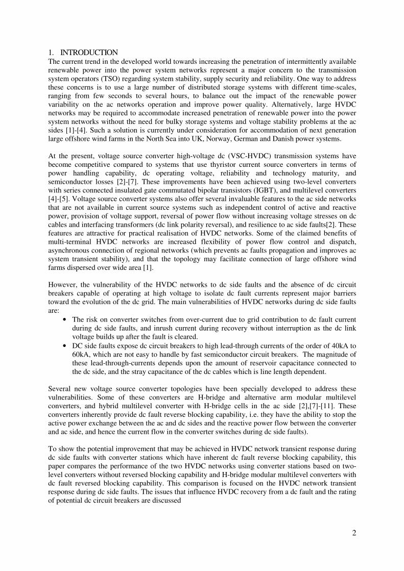
Fig. 2 shows a generic four terminal HVDC network that will be used in this paper to assess the
viability of converters with dc fault reverse blocking capability in improving the resilience of the dc
grid to dc side faults. VSC1 through VSC4 represent converter stations. Converters VSC1 and VSC2
control active power injection into the dc network and regulate ac voltage magnitude at points of
common coupling B1 and B2. VSC3 and VSC4 regulate dc link voltage and ac voltage magnitude at
points of common coupling B3 and B4. In order to assess the possible improvement that can be
achieved in the HVDC network transient response during dc side faults when converters with dc fault
reverse blocking capabilities are employed, the test system in Fig. 2 is simulated first with converters
having inherent dc fault reverse blocking capability (mainly H-bridge M2C) and then with
conventional two-level converters without reverse blocking capability. To maintain reasonable
simulation speed, the H-bridge modular multilevel converters are modelled with two cells per arm and
controlled using sinusoidal pulse width modulation with 2.1kHz switching frequency. A capacitor
voltage balancing method is also incorporated. Both ac and dc transmission lines are represented by
simple lumped π models. Table 1 summarises system parameters.
Fig. 2: Test system
Table 1: System parameters
Two-level H-bridge Converter rating (MVA) 200 200
Dc link voltage (kV) 275 275
Interfacing transformer
200MVA
T1&T2: 230kV/132kV
Z=(0.008+j0.32)pu
T1&T2: 132kV/400kV
Z=(0.008+j0.32)pu
200MVA
T1&T2: 230kV/132kV
Z=(0.008+j0.32)pu
T1&T2: 132kV/400kV
Z=(0.008+j0.32)pu
Interfacing reactors j0.32pu no
Arm reactor - 20mH
Dc link capacitors 500µF 150µF
H-bride cell capacitors - 1000µF
dc lines (150km) Z=(0.0055+j0.0198)pu and C=34.6µF Z=(0.0055+j0.0198) pu and C=34.6µF
A. Case I: HVDC network employing converters with inherent dc fault reverse blocking capability
This section assesses the viability of HVDC converter topologies with inherent dc reverse blocking
capability than can be exploited to improve the resilience of the dc grid to dc side faults. This is tested

6
by subjecting the test system in Fig. 2 to a solid pole-to-pole dc fault at the middle of the line
connecting converters VSC2 and VSC4, with fault duration of 140ms (7 cycles for 50Hz systems).
During the dc fault period, the active power commands to the converters VSC1 and VSC2 are reduced
to zero and pulse width modulation signals to the switches of all converters are inhibited, including
those controlling dc voltages. To prevent the converter station dc link voltages from oscillating against
each other due to the absence of common dc link capacitors when the H-bridge modular converters are
employed in Fig. 2, a small capacitor of 150µF is connected across each converter station dc link to
decouple the oscillations due to capacitor voltage balancing dynamics from the dc network. As a
consequence, the magnitude of the lead-through currents that may flow in the dc side is expected to
increase due to discharge of the these capacitors.
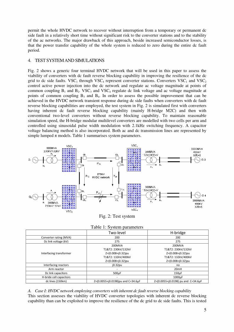
Fig. 3 shows the results obtained when the system in Fig. 2 is subjected to a solid pole-to-pole dc fault
at the middle of the line connecting converters 2 and 4. Figs. 3a and 3b show active and reactive
power that the converter stations exchange with their points of common coupling B1 to B4. Figs. 3c
and 3d show current waveforms converters 1 and 4 inject into B1 and B4. It can be observed from Figs.
3a to 3d that there is no real power exchange between the ac sides and the HVDC network, noreactive
power exchange between the converters and ac systems, and no current flow in the converter switches
during the entire fault period as the converter gate signals are inhibited. Fig. 3e and 3f show the grid
contribution to the dc network during the solid pole-to-pole dc fault. It can be observed that the ac
side’s contribution to the dc fault currents through converter switches is completely eliminated. Also
converter switches experience only manageable current stresses during HVDC network recovery from
the dc fault when the dc side capacitors (reservoir and cable distributed stray capacitance) are
recharging from the ac side as the converters collapsed dc link voltages are building up. Fig. 3g shows
current waveforms at the links 1-3 and 2-4. It can be seen that the current magnitude in these links is
much larger than ac side’s contributions shown in Figs. 3e and 3f. This is because the link currents
include a large transient component due to the discharge of the dc side capacitors. Therefore any dc
circuit breakers must be able to tolerate such a large current for a short period of time, as it decays
quickly, but are not required to be capable of breaking such high current. Fig. 3h shows dc link voltage
of converters 2 and 4. The main issue with HVDC network recovery from dc faults is that the current
magnitude in the converter switches and dc side are limited only by the effective impedance between
points of common coupling and converter terminals (including arm inductors in H-bridge modular
converters), and not the current controller. The current controller becomes effective after dc link
voltage has partially or fully recovered.
(a) Converters 1 and 2 active and reactive power exchange with
B1 and B2
(b) Converters 1 and 2 active and reactive power exchange with
B3 and B4
(c) Current injected by VSC1 into B1
(d) Current injected by VSC4 into B4
7
(e) Converters 1 and 2 dc link currents (grid contribution),
excluding dc side capacitor discharge current
(f) Converter 3 and 4 dc link currents (grid contribution),
excluding dc side capacitor discharge current
(g) DC currents in links connecting converters 1 and 3, and 2 and
4
(h) DC link voltage of converters 2 and 4
Fig. 3: Waveforms demonstrating recovery of the HVDC network that employs converters with dc fault reverse blocking capability
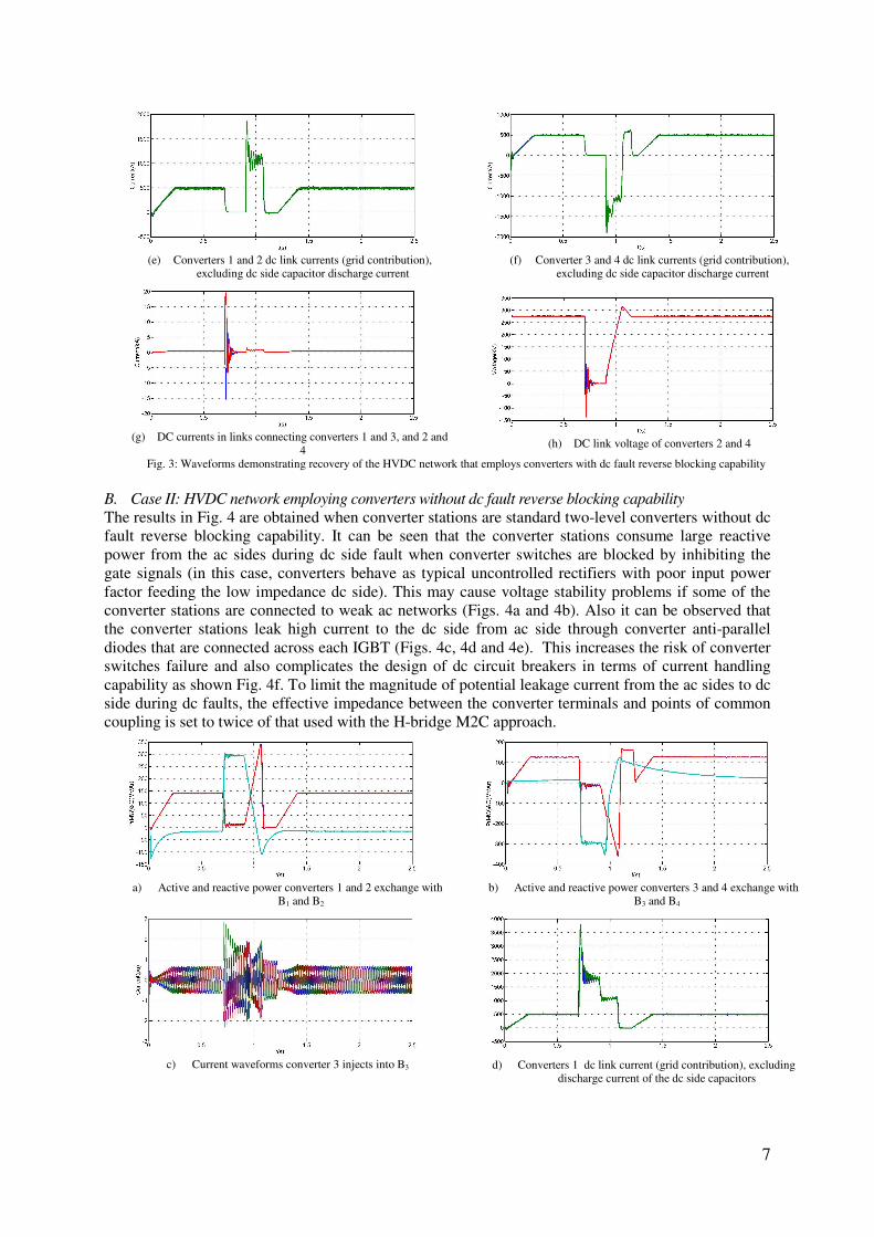
B. Case II: HVDC network employing converters without dc fault reverse blocking capability
The results in Fig. 4 are obtained when converter stations are standard two-level converters without dc
fault reverse blocking capability. It can be seen that the converter stations consume large reactive
power from the ac sides during dc side fault when converter switches are blocked by inhibiting the
gate signals (in this case, converters behave as typical uncontrolled rectifiers with poor input power
factor feeding the low impedance dc side). This may cause voltage stability problems if some of the
converter stations are connected to weak ac networks (Figs. 4a and 4b). Also it can be observed that
the converter stations leak high current to the dc side from ac side through converter anti-parallel
diodes that are connected across each IGBT (Figs. 4c, 4d and 4e). This increases the risk of converter
switches failure and also complicates the design of dc circuit breakers in terms of current handling
capability as shown Fig. 4f. To limit the magnitude of potential leakage current from the ac sides to dc
side during dc faults, the effective impedance between the converter terminals and points of common
coupling is set to twice of that used with the H-bridge M2C approach.
a) Active and reactive power converters 1 and 2 exchange with
B1 and B2
b) Active and reactive power converters 3 and 4 exchange with
B3 and B4
c) Current waveforms converter 3 injects into B3
d) Converters 1 dc link current (grid contribution), excluding
discharge current of the dc side capacitors

8
e) Converter 3 dc link current (grid contribution), excluding
discharge current of the dc side capacitors
f) dc current in the link connecting converters 1 and 3,
including transient contribution of the dc side capacitors
Fig. 4: Sample waveforms demonstrating the recovery of the HVDC network that employs standard two-level converters without dc fault reverse
blocking capability
5. CONCLUSIONS This paper investigated the potential improvement that may be achieved in the transient behavior of
the HVDC network during dc side faults when converter stations with dc fault reverse blocking
capability are employed. The response of the HVDC network during dc side faults is obtained using
converter stations with dc fault reverse blocking capability and compared to that obtained with
standard two-level converters without blocking capability. This paper also highlights the potential
benefits of the dc fault blocking capability feature in the context of the HVDC network, which can be
summarized in the following points:
• Reduces the risk of converter stations damage during dc side faults and recovery period.
• Minimizes the magnitude of the lead-through current dc circuit breakers may experience.
However, this depends on the HVDC converter topology employed (see references [2],[3] and
[8] for more details).
• May permit the use of relatively slow dc circuit breakers with low current breaking capacity
(as ac networks contribution to the fault current are stopped, and the currents in the all
branches of the HVDC network will die out after discharge of the dc side capacitors).
• Recovery without interruption from temporary dc side faults may be possible.
• Improves voltage stability of the ac networks connected to the HVDC network during dc side
faults and system recovery as the amount of reactive powers flow toward the converter
stations are significantly reduced (only during recovery from dc side faults). This is because
during dc side faults ac networks will see the points of common coupling where the converter
stations of the HVDC network are connected as open circuit nodes.
6. REFERENCES [1] G.O. Kalcon et al., “HVDC Network: Wind Power Integration and Creation of Super Grid,” IEEE Electrical Engineering and Environment
International Conference (EEEIC), May 2011.
[2] G. P. Adam, et al., "Network Fault Tolerant Voltage-Source-Converters for High-Voltage Applications," in IET, the 9th International conference
on AC and DC Power Transmission, London, UK, 2010.
[3] G.P. Adam et al., “ H-bridge Modular Multilevel Converter (M2C) for High-Voltage Applications,” CIRED 2011, Frankfurt, Germany, June
2011.
[4] B. Jacobson;, et al., "VSC-HVDC Transmission with Cascaded Two-level Converters," presented at the CIGRE 2010, 2010.
[5] Dirk et al., “Prospects of HVDC&FACTS for Bulk Power Transmission and System Security,” paper available online at SIEMENS website
www.usa.siemens.com.
[6] W. Manfred, K. Arthur and S. Peter, “A Modular Direct Converter for Transformerless Rail Interties,” Proceedings of International Symposium
on Industrial Electronics (ISIE2010), Bari-Italy, 4-7 July 2007,pp.1-6.
[7] M. Hagiwara and H. Akagi, "PWM control and experiment of modular multilevel converters," in Power Electronics Specialists Conference,
2008. PESC 2008. IEEE, 2008, pp. 154-161.
[8] M. Merlin et al., “A new Hybrid Multi-level Voltage Source Converter with DC Fault Blocking Capability,” Paper available at www.supergen-
network.org.uk.
[9] G. P. Adam, et al., "Modular multilevel inverter: Pulse width modulation and capacitor balancing technique," Power Electronics, IET, vol. 3, pp.
702-715, 2010.
[10] Hagar and P. W. Lehn, "A scalable multi-input multi-level voltage sourced converter," in Electrical and Computer Engineering, 2009. CCECE
'09. Canadian Conference on, 2009, pp. 265-268.
[11] N. Flourentzou, et al., "VSC-Based HVDC Power Transmission Systems: An Overview," Power Electronics, IEEE Transactions on, vol. 24, pp.
592-602, 2009.