huygens institute - royal netherlands academy of … · huygens institute - royal netherlands...
TRANSCRIPT

- 1 -
Huygens Institute - Royal Netherlands Academy of Arts and Sciences (KNAW) Citation: Boudin, M. & H. Kamerlingh Onnes, On the measurement of very low temperatures. III. Coefficient ofpressure variation of pure hydrogen between 0° and 100°, in:KNAW, Proceedings, 3, 1900-1901, Amsterdam, 1901, pp. 299-316 This PDF was made on 24 September 2010, from the 'Digital Library' of the Dutch History of Science Web Center (www.dwc.knaw.nl)
> 'Digital Library > Proceedings of the Royal Netherlands Academy of Arts and Sciences (KNAW), http://www.digitallibrary.nl'

- 2 -
( 290 J
Physics. - Communication N0. 60 from the Physical Laboratory at Leiden, by Prof. H. KAMERLINGH ONNES and M. BOUDIN.
"On the measurement of very low temperafur·es. IIl. eoefficient of pr'essure variation of pure hydrogen between 0° and 100°".
(Rend June 30, 1900.)
15. Very careful determinations of the coefficient of pressure variation of pure hydrogen, described by one of us (H. K.O.) in Communication N°. 27 § 8 (Communication to the meeting of June 1896 of whieh this paper is a continuation) have now been made with the large pattern (comp. N°. 27 § § 2 and 3) of the constant volume hydrogen thermometer for low temperatures.
This determination comprises, [the bulb of the thermometer being placed in iee (l.c. § 7) or in steam (l.c. § 8)], measurements of the temperature in the different parts of the apparatus, and lastly measurements of the volume occupied by the gas.
16. The measurement of the pl'essures. The pressure are determined by the difference in height of the mercury menisci in the manometer (§ 2) augmented by the pressure which is exerted on the outer level of the manometer and which is indicated by a mercury barometer placed beside the apparatus 1) 2). The level of the top and the height of the meniscus are read for each of the menisci by a cathetometer. From the height we derive the correction for thc capillarity according to MENDELEJEFF'S table. Thc temperature of each of the mercury-columns is re ad on thermometers, placed symmetrically. Moreover we allow for the diffcrence in height between the top of the manometer column and the lower meniscus of the barometer.
The man0IJ?eter-tube has been described in § § 2 and 3. The barometer the tube of which has a diameter of 14 m.m., has been previously boiled very carefully in vacuo and is protected by a drying tube.
The transportable cathetometer, constructed by the Société Genévoise is an exceedingly good instrument, arranged for differences in height up to 110 cm., alld provided with 3 telescopes 3) in order
1) By dividing the mercury column which indicntes the pressure of the gas in two parts, we l\void the great difficulty which arises whenever we read great difrerences of level owing to the umnanageableness of the cathetometer rE'quired for tbis.
2) 1!'or mensurements in wbich quick rending is more importnnt than bigh preci~ion, we use an aneroide as WIEBE nnd BbTTCHER did. Ztschr. f. lnstr. X. p. ~6. 1890.
3) OUAPPt:IS on his stationary cathetometer has used 3 telescol)es in order to read :I menisci. l\1ém. Bureau Intern. 'I. Vr. p. 31.
- 3 -
~---~-~---~-_._-------------
( soa) to read the 4 menÎsci. For both accurate and quick reading it is of great advantage, not to be obliged to move the slides over the vertical column. Therefore the two lower (or upper) menisci are placed at about the same height and read with the lower (or upper) telescope; the two upper (or lower) menisci with the two other telesccpes 1). A difficulty arises whenever the difference of level to be measured would lie between about 1 and 10 c.m. - 1'hen we cannot adjust for the two levels either with one or with two telescopes, as the construction of the slides does not allow the telescopes to be brought to a smaller distance from each other than 10 c.m. The difficuIty might be solved by using a fourth telescope or another cathetometer with two telescopes. But in § 18 a method is described by which the difficulty can bé avoided, so that we have always been able to read the 4 menisci with one cathetometer and on]y 3 telescopes without readjusting these. Each of the telescopes is provided with an micro~eter-eyepiece (screw-thread 0.25 m. m., and head divided into 100 parts). The micrometer screws have been tested on the exceedingly good apparatus for the measurement of photographic star-plates at the Leiden Observatory, constructed by REPSOLD according to H. G. YAN DE SANDE BAKHUYZEN's 2) indications, which apparatus had kindly been placed at our disposal. The progressive error remained except in one or two teeth (revolutions) below 2 micron. For one of these micrometer screws the formula for the periodic error was computed 3). This was fonnd to be rp (u) = 0.4025 COS. lt
- 0.730 sin. u in divisions of the head, so that for repeated adjustments we may regard this as negligible. The collimation difference of the telescopes have been measured in pairs at long intervals by different observers, the telescope-slides having been removed jn the mean time from the cathetometer-tube and again replaced on it, while thc telescopes had been completely taken to pieces. Still it was found af ter reading on the verniers of the slides:
I-U Dr. DIJKEN. • • • direct 50.26 m.m. 1-11 BOUDIN • • • • " 50.27
lIl-U " 3.12 J Ill-I " 53.38 ~ indirect 50.26
lIl-U " 3.13
1) In the very dillgrumn:utie figure 1, Pl. I, Oomm. 27, only two teleseopes lmve been drawn.
2) H. G. v. D. SANDE BAKHUYZEN, Mesure des elichés d'nprès la méthode des coordonées rectnngulnires (Bulletin, Comité de In Co.rte du ciel, 3e fuse. 1889.)
3) F. KAlSER, Eellige opmerkingen omtrent de periodieke fouten van Micrometer· schroeven. (Vers!. en Med. K. Akarl. v. yv. Amsterdam, 2e Reeks, Deel!. 1866.)

- 4 -
Dr. H. KAMERLINGH ONNES and M. BOUDIN. "On the messurelIl;ent of very low temperatures.
ill. Coefiicient of pressure variation of pure hydrogen between 0° en 100°".
.Proceedings Royal Acad. Amsterdn'll. Vol. IlL
"
PLATE VI •

- 5 -
( 301 J
'fhc correctness of levelling of the cathetometer was tested by the menisci in two communicating mercury-tubes, presenting a difference of azimuth of 90°, anel no elifference in height amounting to 0.01 m.m. was found.
The levels have been tested by the level-tester anel tables have been made of the correctiolls at elistances of 10, 20, 30, 50 e.m. Each time a micrometer head was read, the level on the telescope was also read. The method we followeel was to read the elifference in le\"el observed through the telescopes on a divideel bar scale 1), not on the cathetometer-scale itself. For this purpose we used a standard meter constructed by the Société Genévoise 2) of 120 e.m. length, mounted on a special stand made in the work-shop of the laboratory which couIel turn round a vertical axis and was provided with adjusting screws, rendering it possible to adjust the bar by means of the cathetometer itself to a vertical position. (See PI. V I this paper).
17. The adjttstm en is. The barometer, the manometer, the divided bar, and the cathetometer are' all mounted on stone pillars fixed to a freestone slab, which in its turn rests on one of the fixed pillars of the laboratory. The stoncs are easily mounted and temporarily consolidated by means of plaster to a rigld block of stone.
In order to be able to adjust accurately, the focussing of the telescopes not being altered, it is necessary that two of the three apparatus should be movable. To attain this they are placed on carefully worked metal stands (see PI. VI of this paper) which ean be I moved in two directions at right angles by micrometer screws with handIes. Tho manometer and the scale are placed on the stands; the barometer and the cathetometer are firmly mounted and the telescopes focussed on the barometer menisci. Then the di vided bar is placed vertically anel brought at thc required distance by means of the screws. The adjustment of the manometer into position is more difficult; the best way is to bring one of the sliding motions of the double sledge on which the apparatus is placed in the direction of the cathetometer, nud then to tUl'n the stand and bring
1) CHAPPUIS l.c. p. 31. We aseel tnilled hy n great num ber of measurements, that it Wns not necessary to rend the scale immediate1y aftel a meniscus, but that the mellisci could be read successively and t11e scale ut the beginlling or ut the end of the series of measurements.
~) ISAAcHsEN's test of Hl~ 111\s ShOWll the great nccurocy of these divided bnr senles, comp. Bureau Internat. 1. c. p. 39.
- 6 -
( 302 )
the menisci at the same distance from the cathetometer aDd to adjust them with the screw both at the same time.
18. The elimination of vm'iations in the barometet' pre.~sure, Rapid variations of the atmospheric pressure are an important cause of uncertainty in these measurements of pressure 1). Tbough the telescopes need not be moved along the scale, yet some five minutes must elapse before tbe reading of the four heights is \lomplete, and during tbis time tbe variations in barometric hcight are of ten not negligible.
For example thc readings O!! the 15th Febr. were
2h 762.50 2h30 761.92 3h 761.51 31130 761.30 4h30 760.80
Obviously the resulting uncertainty can be much diminished by a suitable combination of the (l bservations in special cases of the variation. Suppose for instanee that the changes in atmospheric pressure pare linear with time t so that we may put P = Po + n t, fUither suppose that the changes in both limbs are equal and opposite in sense, equally weU in the barometer and manometer. When t = 0, let nl be the lowel' level, 112 the upper level for the manometer, n3
and n.), the same for the barometer, further suppose that the levels are reread at intervals of one minute and that in the formula mentioned the time is measured in minutes. The real pressure is then 112-n1 + n4-113' If we read in the order n1' 114 , n3' 112 then the actual readings are 1117 114 + :/f, 113-2 TC, 112-3 n.
From this we derive I
The combination 123' 111' n2' n4 leads to the same result, while the insertion of the barometer reading between two manometer readings as l1J, 112' 113' 124 , 111' 7/2 also eliminates a linear rise or fall of the atmospheric pressure.
We can aIso find a number of combinatiolls uy which a parabolic variation can be eliminllted.
1) REGNAULT, Mém. de I'fnst. XXI p. 69 snys: Je ne crains pas d'exagérer en posnut 1:'11 hllt qu'on ne peut pos réponclre <l'une mesure bnrométrique à plus de l/lO
de 1I1lJhUJl.tll', qnehlne pedectlOllués que soÎellt u'llilleurs les nppureils ue mesure.

- 7 -
( 303 )
A first reading 111114 1Is '112 gives
nl
n4+n + ie
ns-2n-4ie
112 - 3 n - 9 ie
a second 'lis '11 2 111 n4 gives
ns - 4n -16ie
112 - 5 n - 25?
911 + 6 1l + 36 i!'
114 + 7 n + 49 ie
so that the mean of both gives the pressure at time zero independant of n and ie.
But in the first place we have not eliminated by this process the caprieious variations of pressure which of ten are of considerable importanC'e, and moreover if the pressure in the manometer had been correctly determined at a given moment, we are not even then entitled to assume that this is the pressure of the gas in the reservoir. Especially to be certain of the latter it is desirabIe to remave as far as possible tbe variations in the pressure.
Ta this end the manometer-tube is connected with thc open limb of the barometer by glass tubes of 3 m.m. diameter weIl packed in wool (the wool packing has not been drawn on thc plate, in order not to rendel' the drawing indistinct). In order to diminish the variations of the pressure which accompany the variations in temperature of the air contained in these tubes, a bottle of 2 liters capacity is included in the connections, this bottIe being always immersed in ice shavings prepared with the precautions of § 7 1).
The total volume of gas contained in the manometer, barometer and connecting tubes which is exposed to variations of temperature is about 60 c.c. anel. thence tbe variation of pressure resulting from a change of temperature of 1 deg. O. will be only 0.07 to 0.08 m. m. This changf' can only take place so very slowly and regularly that it may be eliminated by the choice of the order of observations according to the above mentioned methode In a complete series of observations the variations are always Ie ss than 0.1 m. Ul. and are very regular. Thus on the 10th March we observed
1) The whole apparatus ('nn now be eonsidered us a differental nir tllermometer. We think that l'FAUNDLER first llsed slleh an apparntus Sitzb. Wien l2) LXXII, 729. 1876. We founcl further tlmt CALLENDAlt bas proposed to connect the constant pressure air thermometer with a space at stllndllrd pressure in oraer to avoia the reading of mercury columns. Phil. Mag. 5. 48. p. 540. 1899.
- 8 -
( 304 )
Sh 750.47
Sh30 750.50
411 750.51
41130 750.52
This arrangement also allows us to avoid the difficulty mentioned in § 16 as arising from reading the four menisci with only three telescopes. We have only to alter the pressure by a few centimeters in the reserve bottIe and in the tube connecting the barometer and manometer with it in order to arrange that two of the menisci are read either by one or by two telescopes.
19. Detm'mination of the temperatures. We must know the temperature of the reservoir and of thedif
ferent parts of the connecting space, which latter consists of the thermometer capillary outside the constant temperature bath, the steel capillary and the volume near the point of the manometertube (comp. Comm. N°. 27 § 2 and Pl. II, fig. 4a) where the àdjustments of the meniscus for constant volume are made.
During the determination of the zero the thermometer reservoir and about 30 cm. of the capillary are immersed in shavings of ice (§ 7) . .A thermometer gives the temperature of the remainder of the capillary w hich has only a very small volume.
Three thermometers are placed against the steel capillary and divide this into two parts for tbe tempprature of eacb of which we assume the mean of those observerl at the ends.
For the temperature of the volume near the steel point we read the last thermometer on the steel capillary and thosp on ea(\h side of the manometer. These differ on1y by two or three tenths of a degree.
During the determination of the boiling-point the reservoir and nearly the whole of the glass capillary is immersed in the boiling apparatus. The temperature of eLullition is computed from BROCH'S
tabJes 1), in connection with which we used the value 9 = 9.81318 2) at Leiden. The difference of pressure observed by the small water manometer (comp. § 8), was allowed for.
The atmospheric pressure is read by an aneroide, which is repeatedJy controlled by the barometer.
The remaining 10 cm. of the capillal'y reach above the boiling
/
\) GUILLAUME, Thertnornétrie ue précision, pag. 3fZ7. 2) lJetermmution by lJEFrORGES IInd BOURGEOIS lSQ2.

- 9 -
( 305 )
apparatus; far this part the mean of the temperature of the boiling apparatus and of the first thermometer against the steel capillary was taken; the temperature of the stepl capillary itself is accounted for as in the determination of thc zero.
Special precautions have to be taken, that the temperature of the steel capillary should not be toa uncertain owing to the rising hot vapours and radiation.
At a time when the steel capillary was packed only in waal, but otherwise the arrangement af the boiling apparatus was that shawn in Communication N°. 27 PI. lIL, fig. 1 we read on the three thermometers:
31l 30
4 30
, . 1
And sa the means were rather uncertain, due especially to the canduction of heat which takes place at the beginning of the capillary.
To secure a more satisfactary protection of the capillary an indiarubber spiral with water-circulation was placed on the thick wool packing of the boiling apparatus, above this again large sheets of paper were stretched at a few centimeters distance from each other. Where the capillary passed through these protecting layers, which shielded it from radiation care was taken that it fitted weIl in the openings sa that na hat air cauld pass.
The ascending hot vapours at the sides of the boiling-apparatus were conducted at two meters distance from this through a chimney made also of large sheets of paper, which were slightly inclined and fitted weIl against the apparatus. With these simple arrangements we succeeded in keeping the differences of temperature alang the capillary within the ·same limits as l in the zero-determinations, and hence they only depend upon the temperature of the room.
Thus on March 10 we observed:
15°,6 ' 15°,2
15°,4 15°,1
No special precautions were taken to keep the temperature of the raam constant. It is not difficult by means of heating and ventilating to arrange that the variations of temperature do not exceed 1 deg. C. in j1 series of obseryations.
The influence of the various sources of error resulting from the uncertainty of the temperature determinations is considered in § 24.
- 10 -
( 306 )
20. The measurement of the volumes. Tbe calibration of tbe glass parts of tbe apparatuA bas been described in S 2. Tbe steel capiIlary bas first been separately calibrated (fiUed by means of the mercury pump), and again af ter having been connected to tbe volumenometer tube, in wbich case they are also filled by means of tbe mercury pump. In this way the whole connecting spaC'e is determined at one time. As the upper part of the volumenometer tube has also been calibrated (Comm. N°. 27, p. 6) the two methods includE' a mutual test.
3 measurements by the first ~ method gave on anaverage 749 mm3•1)
5 » »» second » »»» » 7 5 2 »
The volume of the meniscus which we want for the determination of the volume of the gas shut off hy it, cannot in a tube of the dimensions used, be considered as a constant 2), derived from tbe diameter and a definite assumed angle of contact. For the height of tbc meniscus varied between 1.38 m. m. and 1.54 m. m., which corresponds to a change of volume of about 10 m.m.s, if tbe top of the meniscus is stationary, an accidental error that cannot be admitted as we shall see later. The volumes are computed in each case from the height and the diameter like that of a spherical segment. The systematic error which then remains may be considered to be smaIl enough to be neglected (comp. § 24). We intend to determine this volume still more accurately by fixing several points, say three, to the upper surface of the connecting space, along one diameter, and to measure the vertical distance of each of these 3 from tbe mercury, in order to determine the true profile of the meniscus.
As a meniscus of 1.46 m.m. height occurred repeatedly, we have considered this as the normal meniscus in a way to be later described more in detail.
The coefficient of dilatation of the Jena-glass 16III used indicated by Ic was determined by us between 0° C. and 100° C. according to the method of the weight-thermometer. We found Ic = 0.0000242. The smaH difference from the value generaHy given for 16III i. e. 0.0000244 S) does not excecd the probable error. The variation of
1) The vnlue 750 mm~. was taken af ter comparing tbe nccurncy of each method.
2) As done by CHA.l'PUlS 1. c. p. 51.
S) WIEBE nnd BOT'l'CHER 1. c give 0.0000240.
- 11 -
( 307 )
the volume under the influence of the pressure was determined as in § 2. With a pressure of 1 atm., the variation of volume of the reservoir was 4.64 m.m.3 at 15° C. We intend to determine the amount of this correction for 0° C. and for 100° C. separately. For the time being we have applied the correction found for 15° invariably at 0° C. and at 100° C.
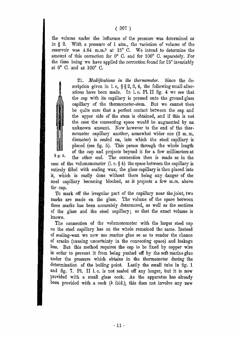
21. Modifications in the thermometer. 8ince the description given in 1. c, § § 2, 3, 4, the following small alterations have been made. In 1. c. PI. II fig. 4 we see that the CfLp with its capillary is pressed onto the ground glass capillary of the thermometer-stem. But we cannot then be quite sure that a perfect contact between the cap and the upper side of the stem is obtained, and if this is not the case the connecting space would be augmented by an unknown amount. N ow ho wever to the end of the thermometer capillary another, somewhat wider one (2 m. m. diameter) is sealed on, into which the steel capillary is placed (see fig. 5). This pa'3ses through the whole length of the cap and projects beyond it for a few millimeters at
.I! g. 5. the other end. The connection then is made as in the case of tbe volumenometer (1. c. § 4) the space between the capillary is entirely filled with sealing wax, the glass capillary is then placed into it, which is easily done without th ere being any danger of the steel capillary becoming blocked, as it projects a few m.m. ahove the cap.
To mark off the irregular part of the capillary near the joint, two marks are made on the glass. The volume of the space between these marks has been accurately determmed, as weIl as the sections of tbe glass and the steel capillal'Y j so that the exact volume is known.
The connection of the volumenometer with tbe larger steel cap on the steel capillary has on the whole remained the same. Instead of sl:laling-wax we now use marine glue so as to render the chance of cracks (causing uncertainty in the t'onnecting space) and leakage less. But this method requires the cap to be fixed by copper wire in order to prevent it from being pushed oft' by the soft marine glue under the pressure which obtains in the thermometer during the determination of the boiling point. Lastly the small tube in fig. 1 and fig. 7. PI. II 1. C. is not sealed oft' any longer, but it is now provided with a smaIl glass cock. As the apparatus has already been providcd witb a cock (k ibid.), this does not involve any new
- 12 -
( 308 )
difficultYi the new cock is very usefu1 whenever we want to alter the pressure of the gas, or to fill the thermometer with another gas.
22. Tlle preparation of the pure hydrogene Tbe apparatus used for th is purpose (1. C. § 5) has a180 undergone a few small alterations. In the first p1ace severa1 indiarubber connectións have been removed. 'fhe two storage-bott1es fol' hydrochloric acid and potassium hydroxide solution (d and e fig. 3 PI. I comm. nO. 27) are now 1ike the W OULF'S wash bottle closed with ground stoppers ano the screw clamp C has been~replaced by a mercury-closure. The large drying-towers i, i are replaced by a U-shaped tube, closed with ground glass stoppers. Even with careful heating of both the glass and the india-rubber, it requires much care to make indiarubber fittings on glass by means of sealing wax perfectly trustworthy; if as often is the case some solution of india-rubber is applied between the glass and the india-rubber, the solvent evaporates in the vacuum and the high degree of purity, as we require it for our hydrogen, is altogether lost.
Lastly for the pre1iminary filling we no longer use commercial hydrogen, but hydrogen prepared from pure zinc and hydrochloric acid in a separate glass apparatus.
23. The calc1,dation of results. Our determination comprises the reading of the menisci and of the various thermometers.
Suppose the reservoir is at {'(J. Let ET be the pressure of the included gas corrected for the temperature of the mercury and the compression of the latter under its own weight (to be neglf'cted)j the correction applying for the value of gravitation will be dlscussed later.
Let Va be the volume of the reservoir at 0° C and under the pressure of the gas during that time.
1~1 the volume of that part of the glass capillary which is at the temperature t of the reservoir.
U2 the volume of that part of the glass capillary which is not at the temperature of the reservoir but at the temperature t2•
Us and U4, the volumes of those parts of the steel capillary where the temperatures are ts and t4,.
Ua the volume near the steel point in the volumenometer.
(i the variation of the volume Va of the reservoir caused by \
the pres8ure.
- 13 -
( 309 )
The volume U5 and the temperatures are different for different determinations, therefore it is desirable to apply corrections which reduco them to a definitc volume U5 and definite temperatures.
From the temperatures observed we caleulate the pressure, which would be found under the following eircumstanccs: thc wbole of the thermometer eapillary is reduced togethrr with the glass reservoir to the same temperature {)oG, dilfering very little from t. Moreover the entire connecting space must be reduced to 15° Gand this space must be closed by a meniscus of 1.44 m.m. height touching the point of adjustment in the volumenometer-iube. L('t u be tbe conneeting space thns determined. U nder these cireumstanees the following equation will hold for the pressure, whieh we eaU the reduced pressure Ho.
in whieh k is the eoeffieient of expansion of the glass and a the coeffieient of pressure variation of the gas between 0° C. and ()O C.
The differenees of the small u's at the temperature of calibration and at the temperature of observation are too small to he aeeounted for 1). Tho corrections from HT to Ho are made with an approximate value of a, for which we took 0,003662.
The values of (), whieh are now important to us, are 0° C. and 100° C. For all corrections at the same temperature the value of Ho is a definite amount, whieh therefore ean be ealeulated onee for all. The ealeulation of the value ~etween [] to the left may be
shortened by eomputing tables of the valucs of Un
,as the l+a tn
temperatures ts , t4, t5 never deviate mueh from 15° C. 2).
The pressures rerlueed in this way eorrespond therefol'e to the following circumstances:
At 0° C. a vohune Vo + UI + U2 at the temperature 0°
u "" _" 15° At 100° C. the volume of the reservoir has become
J) As for UJ, this volume itse1f is e\.tlemely smnll, aud. ns fol' 1/2 , U., U4 , liG tbe dlfterellce of t2 , t3 , t4 , tG from the assumed stulldard tempelature 15° C. is very smal!.
2) OHAPPUIS 1. c. pg. 55. 21
Proceedlllgs noyal Acad. Amsterdam Vol. IIl.

- 14 -
( 310 )
Vo (1 + 100 k) + fj,
and hence the circumstances are:
Vo (I + 100 k) + fj + UI + te2 at the temperature 1000
u 1~ 11 11 11
a is then found from 1)
[U] [(VO+ltl+u2)(1+100k)+/1 U]
Ho VO+Ul+U2+ 1+15a =H:oo 1+100 a + 1+15a
~ - u I BlOO-H. ( (1+100a) 1- 0 ==
VO+Ul+U2 1+15a Ho
= Hl 00 [1+100k+ fj J (2) Ho VO+Ul+ U2
This equation can be solved by successive approximations, bearing in mind that BlOO and Bo include correctioDs ilepending on a. HIOO
and Ho might then be computed anew with the new' value of ~, and the equation solved anew. The number 0,003662 used by us in the first approximation is in such good agreement with the correct soJ uti on, that in this case it was not necessary to make a second series of calculations.
24. Influence of en'ors 2). 100 du = dh is easily found when dIt Ho
is the error in one of the determina tions of pressure H100 or Ho. For the accuracy of reading with a cathetorneter we may assume
dil, = 0,=01 mrn., and to this value corresponds du = 10-7, an error which will be perceptible as a unit in the seventh place of decimals and would change the value 0,0036627 into for example 0,0036628. The other errors are best considered hy reducing them to errors in the reading of pressure. As for the connecting space which as compared to the reservoir was very large (over 0,01) 3) owing to the special arrangement of the thermometer for very low temperatures, a reading error in the distance from the meniscus to the point of 0,01 mm., which corresponds to 1,2 mms error in u, gives an error
1) Comp. CHll'PUIS l.c. p. 52. ') Comp. OHAPPUIS, l. c. p. 56. WIEBE en BÖTTOHER, Zeitschr. f. Instrumentenkunde 10, p. 238. 1890. 3) As in the case WIEBE and BÖTTOHER l.c.
- 15 -
( 311 )
of 0,01 mmo in the pressure at the zero or 0,02 mmo in the pressure at the boiling point; incorrect determination of volume of parts of the connecting space causes a similar systematic error.
The capi11arity leaves an uncertainty which we estimate at less than 0.03 m. m., the volume corresponding to the uncertainty of the form of the meniscus remains below 3 m. m.s, corresponding to 0.03 m. m. and 0.06 m. m. in the pressure ; the systematic error, which thus can arise in Cf does not reach 3.10-7•
An error of 0.°01 C in the boiling point gives an error of 0.04 in the pressure ; 0.°2 a error in the temperature of the capillary changes the pressure about 0 01 m. m. near the zero. In this respect no other than accidental errors are to be feared. Taking all toge-ther an accidental error of say 3 units in the last decimal (10.7) is to be feared. The systematic error may re ach the same value.
To illustrate the favourable influence of the precautions mentioned in § § 18 and 19, especially of those relating to the removal of the variation of the atmospheric pressure, we give here a few observations of the zero, made in February without these precautions but otherwise under the same circumstances as the series of March in § 26.
In February In March we found on 4 days: we found on 3 days:
Ho = 1098.24 Ho = 1098.35 1098.15 1098.36 1098.08 1098.37 1098.65
In the first series the dcviation from thc mean ris es to 0.4 m.m., which corresponds to Dearly 00 .1 in temperature, a sufficient accuracy it is true for most determinations at low tempel'atures, but much smaller than we have attained with' our apparatus when all the above mentioned prècautions have been taken. Thc deviation 0.01 m. m. from the mean in the series treated in the latter wav
" corresponds to 00 .02 or as mentioned above to a unit in the seventh decimal of the coefficient of pressure variation.
At ,the boiling point we found on 3 days (comp. § 26). RIOO = 1491.04
1491.00 1491.05
The deviation is here twice as large, but yet exceedingly smalI, whereas formerly, wh en the capillary was not so wen protected, deviations of several tenths of m' m. occurred.
It is therefore useless to COIlsicler the previous determinations of the zero and the boiling point with a view to the coefficient of
21*

- 16 -
( 312 )
pressure variation to be derived from each pair of them. These are only of importance for the measurements at very low temperatures made at the time.
25. Survey of a determination. In the annexed table all the readings of one determillation are given, but in order not to make the sclleme too intricate the mea.ns of usually three single readings which never differ by more than a few hundredths, are given as the normal readings.
Column A gives the reading on the micrometer heads of the cathe-
March 10 3 10 I A. I i I c. ( D. I E. I F. ~ -------
Point.
lower meniscus.
upper menIsous.
lower meniscus.
upper memscus.
lower meniscus.
upper meniscus
Point.
op.
ba sis.
to p.
b asis.
to p.
b asis.
p. to
ba sis.
to p.
b asis.
p. to
ba sis.
24.19
24.36
27.44
20.37
21.\)7
21.42
22.20
7.8B
8.99
24.41
27.43
20.40
21.90
24.22
5.5 1028 23.42 5.5 1029 25.51 5.5
1028 23.42 5.5 5.5 1029 25.51 5.5 6.0 1029 25.51 5.7
1030 27.61 5.7
7.0 282 18.86 7.0 283 20.86 7.0 283 20.86 7.0 7.0 284 22.89 7.0
5.5 1027 21.30 5.5 1028 23.42 5.5
5.5 1027 21.30 5.5 1028 ~3.42 5.5
6.0 276 6.70 6.0 277 B.73 6.0
6.0 277 8.73 6.0 278 10.75 6.0
5.2 1028 23.42 0.5 1029 25.51 5.5
6.0 1029 25.51 5.7 1030 27.61 5.7
6.8 282 18.86 7.0 283 20.86 7.0
7.0 283 20.B6 7.0 284 22.89 7.0
5.5 1028 23.42 5.5 1029 25.51 5.5
Aneroïde 771.3 Temp. 14°,3 Water-manometer + 1 mMo
--
15°0 16°2 14°8 15°8 14°5
15°6 15°6 \
14°2 14°6
15°2 16°5 }4°0 16°0 14°4
16°0 15°2
tom eter telescopes, B gives the reading on the levels of those telcscopes 1), C the nearest division of the graduation on the standardmeter 2), D and E the readings of the head and the readings of the
1) This rending is not mentiolled by CUAPPUIS.
2) Comp. footnote 1, p. 6.

- 17 -
( 313 )
levels during the adjustments to those divisions. The three last columns refer to the tempel;atures. F givcs the temperatures readings of the manometer and the harometer, G those of the capillary, H of the standarc1 scale.
With these numbers we first compute the readings on the standardmeter, with allowance for the levels. Then the thermometer readings are corrected.
In the next table column A' gives the level of the top of each meniscus and the value of the height of each meniscus.
Column B' gives this level corrected for the capillary depression. 0' the corrected temperature of the mereury columns. D' the corrected temperature of the capillary. E' the sum of the mercury columns corrected for the temperature and lastly F' the distance from the top of thc meniscus to the point.
Al I BI' I C' , I D' E' F'
~\ Jower meniscus. 102S.45 1028 2\l 1~,o4 .
height. 1.46 13.9
JI upper meniscus. 282.76 282.69 15.0 15°6 = mm
height. 0.76 15°2 1492.57 0.09
lower meniscus. 1027.05 1027.05 15°0 ,,:
height. 0.37 14.2 '" 1)
@ upper meniscus. 276.58 276.58 14,.5 10
P=l height. 0.54 ,
Pressure of the water-yapour 771. 6 m.m. Leiden.
" " " 771.25 level of the sea 45° L.
From the meaDS in pairs of column D' follows the temperature of the capi11ary, from the height of the meniscus and the distance from the meniscus to the point given jn F' follows the correction for the space between the horizontal plane through the point and the meniscus. A correction 0.07 m.m. for the difference in level of barometer and manometer is then applied to the pressure according to the law of thc communicating tubes 1).
1) The difference of pressure between reservoir and manometer - a cor,rection tbe ne?essity of which was l'emarkecl by Dl'. V. EVERDII\GEN - could be neglected. the gas bemg hydrogen and the diJi'erence of level of reservoir aml munometer small.
- 18 -
( 314 )
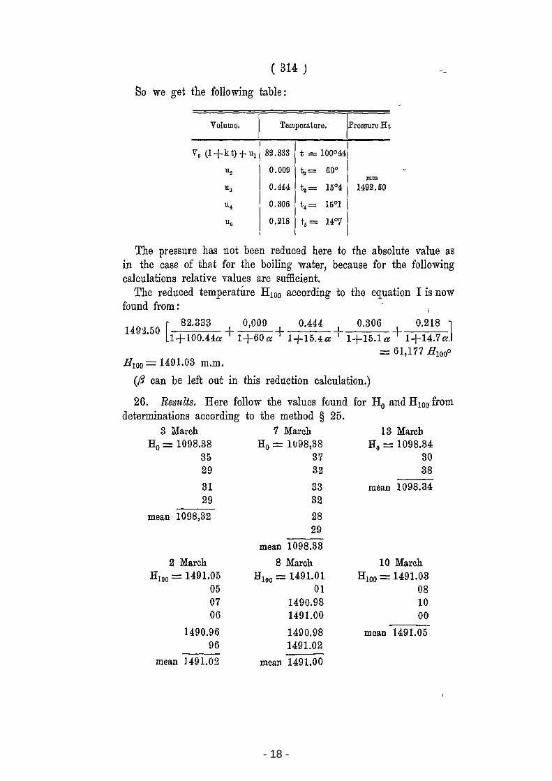
ISo we get the following tabIe:
Volume. Temperature. Pressure Ht
Vo (l+kt)+ul 82.333 t = 100°44
ua 0.009 ta= 60° mm
Us 0.444 ts = 15°4 1492.50
u4 0.306 t4 = 150 1
Uó 0.218 tó= 140 7
The pressure has not been reduced here to the absolute value as in the case of that for the boiling water, because for the following calculations relative values are sufficient.
The reduced temperature HIOO according to the equation I is now faund from:
[ 82.333 O,OOD 0.444 0.306 0.218 ]
149') 50 -'I. 1+l00.44a + 1+60a + 1+15.4a + 1+15.1 a + 1+14.7a.
= 61,177 HIOOo
B IOO = 1491.03 m.m.
((3 can be left out in this reduction calculation.)
26. Results. Here follow the valucs found for Ho and R IOO from determinations accarding ta the method § 25.
3 March 7 March Ho = 1098.38 Ba = 11J98,38
35 37 29 32
31 29
mean 1098,32
2 March HIOO = 1491.05
05 07 06
1490.96 96
mean ]491.02
33 32
28 29
mean 1098.33
8 March HIOO = 1491.01
01 1490.98 1491.00
1490.98 1491.02
mean 1491.00
13 March Bo = 1098.34
30 38
mean 1098.34
10 March H lOO = 1491.03
08 10 00
----mean 1491.05
- 19 -
( 315 )
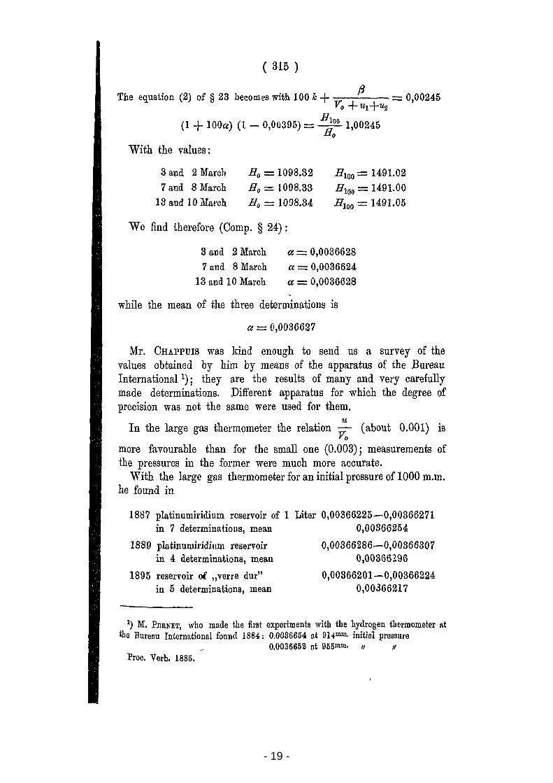
The equation (2) of § 23 becomes with 100 Tc + v. fi = 0,00245 o + ul+u2
(1 -I- 100ce) (1 - 0,00395) = ~:O 1,00245
With the values:
3 and 2 Marcl,
7 and 8 March
13 and 10 Mal'ch
Ho = 1098.32
Ho = 1008.33
Ho = 1008.34
We find t.herefore (Comp. § 24) :
B IOO = 1491.02 H IOO = 1491.00 B 100 = 1491.05
3 and 2 March
7 and 8 March
13 aud 10 March
a = 0,0036628 a = 0,0036624
a = 0,0036628
while the mean of the three determinations is
a = 0,0036627
Mr. CHAPPUIS was kind enough to seud us a survey of the values obtained by him by means of the apparatus of the Bureau International 1) j they are the results of many :md vel'y carefully made determinations. Different apparatus for which the degree of precision was not the same were used for them.
u: In the large gas thermometer the relation V
o (about 0.001) is
more favourable than for the smail one (0.003) j measurements of the pressurcs in the former were much more accurate.
With the large gas thermometer for all initial pressure of 1000 m.m. he found in
1887 platinumiridium reservoir of 1 in 7 determinatiolls, mean
1889 platinumil'idillill reservoir in 4 determinations, mean
1895 reservoir of "verre dut" in 5 determinations, mean
Liter 0,00366225-0,00366271 0,00866254
0,00366286-0,00866307 0,00366196
0,00366201-0,00366224 0,00366217
1) M. P.nUNET, who made the first experiments with the hydrogen tb€'rmometer at the Bureau International found 1884: 0.0086654 at 914mm. initinl pressUl'e
0.0086652 ot 955mm. 11 11
Proc. Verb. 1885.
- 20 -
( 316 )
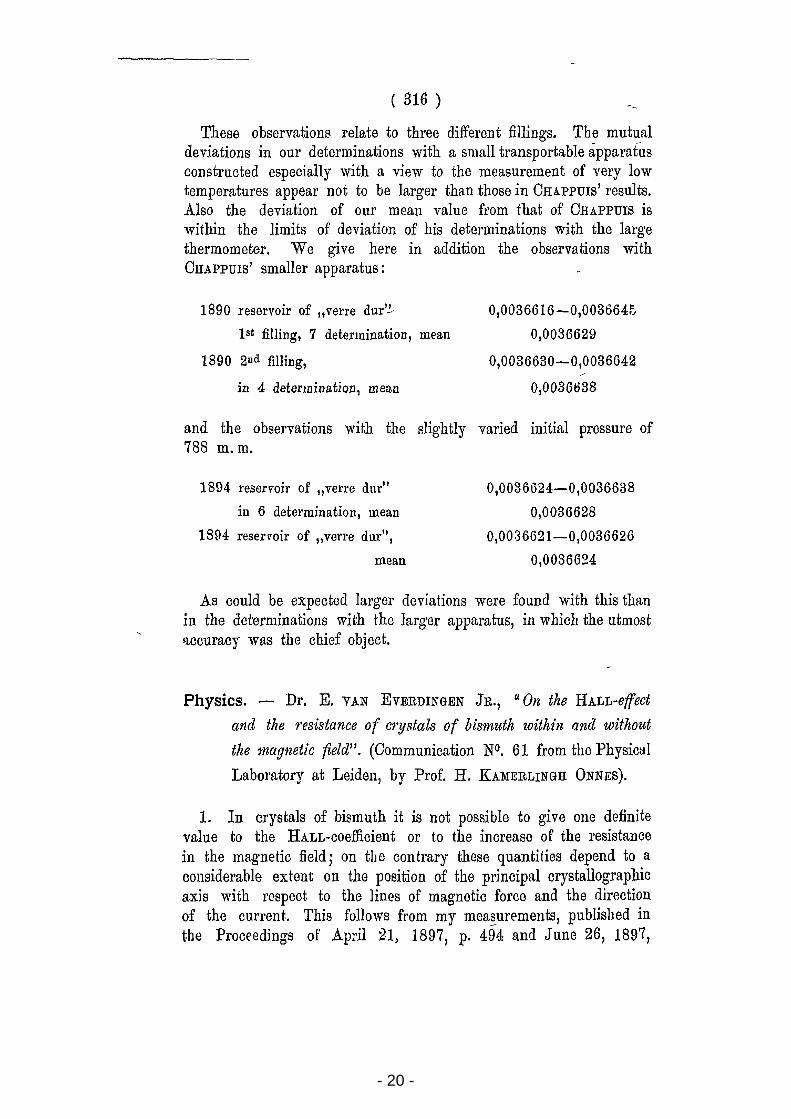
These observations relate to three different fil1ings. The mutual deviations in our determinations with a small transportable ápparatus constructed especially with a view to thc measul'ement of Yery low tempel'atures appeal' not to be larger than those in OHAPPUIS' results . .Also the deviation of our mean value from that of OHAPPUIS is within the limits of deviation of his determinations with the large thermometer. We give here in addition the observations with OHAPPUlS' smaller apparatus:
1890 reservoir of "verre dur'!..
lat filling, 7 detel'mination, mean
1890 211d filling,
in 4 determination, meao
0,0036616-0,003664fJ
0,0036629
0,0036630-0,0036642
0,0036638
and the observations with the Blightly varied initial pressure of 788 m. m.
1894 reservoir of "verre dur"
in 6 determination, mean
1894 resel'l'oir of "verre dur",
mean
0,0036624-0,0036638
0,0036628
0,0036621-0,0036626
0,0036624
As could be expected larger dcviations were found with this than in the determinations with the larger apparatus, in which the utmost !l.ccuracy was the chief object.
Physics. - Dr. E. VAN EVERDINGEN JR., "On the HALL-effect
and the resistance of cry.'ltals of bismuth within and without
the magnetic field". (Oommunication N0. 61 from thc Physical
Laboratory at Leiden, by Prof. H. KAMERLINGH ONNES).
1. In crystals of bismuth it is not possible to give one definite value to the HALL-coefficient or to the increasc of the resistance in the magnetic field; on the contrary these quantities depend to a cOllsiderable extent on the position of thc principal crystallographic axis with respect to the lines of magnctic force and thc direction of the current. This follows from my mea~ur€'ments, published in tbe Proceedings of Ap:il 21, 1897, p. 494 and June 26, 1897,