hunter 170 owners manual - wordpress.comthat luhrs' alura fiberglass division was lo- cated. in...
TRANSCRIPT

5 Colton Road East Lyme, CT 06333
T 860-739-3033 F 860-739-2905
~unter~omposite~echnologies Corp.
HUNTER 170 OWNERS MANUAL
HUNTER COMPOSITE TECHNOLOGIES 5 COLTON ROAD
EAST LYME,CT 06333 pH: (860) 739-3033
FAX: (860) 739-2905 E-MAIL: [email protected]

Welcome to
THE HUNTER MARINE FAMILY Congratulations on your new sailing yacht manufactured by Hunter Marine. We have en- gineered and constructed your boat to be as fine a yacht as any afloat. In order to get the best performance and most enjoyment from your boat you should be familiar with its vari- ous elements and their functions. For your sailing pleasure and safety, please take time to study this manual.
We stand behind the quality of your boat with a warranty, which you should review. To in- sure the validity of your warranty, please com- plete the attached card and send it to us within ten (1 0) days of the purchase date. Section 15 of the U.S. Federal Boat Safety Act requires registration of a boat's first owner. The war- ranty data should also be recorded in the space below for your own reference.
This manual has been compiled to help you operate your craft with safety and pleasure. It
contains details of the craft; equipment sup- plied or fitted, systems, and information on operation and maintenance. Please read it carefully, and familiarize yourself with the craft before using it. If this is your first sailboat or you are changing to a type of craft you are not familiar with, please ensure that you obtain proper handling and operating experience be- fore you assume command of the craft. Your dealer or national sailing federation or yacht club will be pleased to advise you of local sea schools or competent instructors.
PLEASE KEEP THlS MANUAL IN A SAFE PLACE AND HAND IT OVER TO THE NEW OWNER IF YOU SELL THE CRAFT.
You should also complete the warranty cards for your engine, stove, head, electric water pump and other accessories. These are en- closed in the manufacturers' manuals that are packaged with your owner's manual.
OWNER INFORMA TION CARD HULL IDENTIFICATION NUMBER IS ON THE STARBOARD AFT SIDE OF THE HULL OR TRANSOM. THlS NUMBER MUST BE GIVEN IN ALL NECESSARY CORRESPONDENCE.
HULL NO. DATE DELIVERED TO OWNER
YACHT NAME
OWNER NAME
STREET ADDRESS
CITY STA TE/COUNTRY ZIP CODE
HOME PORT
ENGINE MODEL SERIAL NO. PROPELLER SIZE
DEALER PHONE
STREET ADDRESS
CITY STATE/COUNTRY ZIP CODE
PAGE 1

HUNTER MARINE LIMITED WA RRA N N
LIMITED ONE-YEAR WARRANTY Hunter Marine warrants to the first-use pur- for a period of twelve (12) months from the chaser and any subsequent owner during the date of delivery to the first-use purchaser un- warranty period, that any part manufactured der normal use and- service. During this pe- by Hunter will be free of defects caused by riod, Hunter will repair or replace any part faulty workmanship or materials judged to be defective by Hunter.
LIMITED FIVE-YEAR HULL STRUCTURE Hunter warrants to the first-use purchaser This limited warranty applies only to the struc- and any subsequent owner during the war- tural integrity of the hull and supporting ranty period that the hull of each boat will be pantgrid or stringer system. The obligation of free from structural defects in materials and Hunter under this limited warranty is restricted workmanship for a period of five (5) years to the repair or replacement of hulls that are from the date of delivery to the first-use pur- determined to be structurally defective. chaser under normal use and service.
RESTRICTIONS APPLICABLE TO WARRANTIES These limited warranties do not cover the PURCHASER ACKNOWLEDGES THAT NO following: OTHER REPRESENTATIONS WERE MADE
TO HIM OR HER WITH RESPECT TO THE (1) Problems caused by improper maintenance, QUALITY AND FUNCTION OF THE BOAT. storage, cradling, blocking, normal wear and ANY CONSEQUENTIAL DAMAGES THAT tear, misuse, neglect, accident, corrosion, elec- MAY BE INCURRED ARE EXCLUDED AND trolysis or improper operation. JUDGES DEFECTIVE BY HUNTER.
SOMESTATES OR COUNTRIES DO NOT THIS WARRANTY IS EXPRESSLY IN LIEU ALLOW THE EXCLUSION OF INCIDENTAL OF ANY AND ALL OTHER REMEDIES AND OR CONSEQUENTIAL DAMAGES, SO THE WARRANTIES EXPRESSED AND IMPLIED, ABOVE LIMITATION OR EXCLUSION MAY INCLUDING THE WARRANTIES OF NOT APPLY TO YOU. THIS WARRANTY MERCHANTABILITY AND FITNESS. SOME GIVES YOU SPECIFIC LEGAL RIGHTS, AND STATES OR COUNTRIES DO NOT ALLOW YOU MAY ALSO HAVE OTHER RIGHTS LIMITATIONS ON HOW LONG AN IMPLIED THAT VARY FROM STATE TO STATE OR WARRANTY LASTS, SO THE ABOVE COUNTRY TO COUNTRY. LIMITATION MAY NOT APPLY TO YOU. THE
PAGE 2

HUNTER MARINE LIMITED WA RRA N7Y
WARRANTY REGISTRATION These limited warranties shall not be effective replacements will be made by an authorized unless the Hunter Warranty Registration Form Hunter dealer, or at the option of Hunter, at the and Pre-Delivery Service Record, which are Hunter plant. If the repairs are of such a nature furnished with each new boat, are filled out that the warranty work must be performed at completely and returned to Hunter within the Hunter plant, the owner shall pay transpor- fifteen (1 5) days of delivery. Responsibility for tation costs to and from the Hunter plant. The sending the completed Registration Form labor cost reimbursement will be based on a remains with the dealer. labor allowance schedule established by
Hunter and where not applicable, on a reason- It is critical that the Warranty Registration able number of hours as determined by Hunter. Form is signed by both the dealer and the An authorized Hunter service representative owner and returned to Hunter. Warranty . must approve any repairs and replacements in coverage cannot be initiated until Hunter advance. receives the completed form. All repairs and/or
TRANSFER OF LIMITED WARRANTIES Limited warranties will be transferred to a sub- (2) The notice shall include the name, address sequent purchaser of the boat if: and telephone number of the subsequent pur-
chaser, the date of purchase, the hull number, (1) A notice of the transfer of ownership of the and the name of the seller of the boat.
boat is given by the subsequent purchaser in writing to Hunter within thirty (30) days of the Hunter will mail notice of expiration dates of the transfer. limited warranties to the subsequent owner. The
transfer of the ownership of the will not extend the expiration dates of the limited warranties.
CUSTOMER SATISFACTION SURVEY During the first year of ownership, the first The second survey (CSS #2) is given nine to purchaser will receive two Customer Satisfac- ten months into ownership, and primarily gives tion Surveys: the first (CSS #I) will be re- the customer an opportunity to evaluate dealer ceived shortly after taking delivery and fo- service capability and the boat's functional sys- cuses on the customer's experience with the tems and characteristics. Both surveys are dealer and commissioning of the boat, and the contingent upon receipt of the first purchaser's owner's initial satisfaction. Warranty Registration form.
PAGE 3

HUNTER MARINE'S OWNER AND FOUNDER
WARREN R. LUHRS BRIEF BACKGROUND
Warren Luhrs was born in East Orange, New Jersey in 1944 into a family with an estab- lished tradition in the maritime and transporta- tion industries. His great-grandfather, Henry, was a railroad and clipper-shipping pioneer in America, while his great-uncle John helped build the famous St. Petersburg to Moscow railroad for Czar Alexander II.
Henry Luhrs owned shares in twenty-two different ocean-going vessels - barks, brigs, and schooners - and was the principal owner of the bark Sophia R. Luhrs, named for his wife. He was also a partner with Albert Sprout, who managed the shipyard where the Sophia R. Luhrs was built in Melbridge, Maine.
Warren Luhrs' father Henry worked at a small boat manufacturer in Morgan, New Jersey, and later started his own company, continuing the Luhrs' family sea tradition during the great depression. During World War II he repaired boats and installed ice sheathing on their bows for the Coast Guard.
After the War, Henry built 27-foot fishing boats and in 1948 began to construct custom-built pleasure craft. He then turned to skiffs and in 1952 incorporated as Henry Luhrs Sea Skiffs, where he constructed lapstrake sea skiffs using assembly-line techniques. Henry personally "shook down" his prototypes on family trips up the Hudson River to Lake Champlain.
The sea skiff is a class of boat that has been very popular, owing to its seaworthiness. It features a sharp bow, which reduces pounding in surf or choppy seas, and a hull whose forward section is rounded below the waterline to increase stability in rough water or a following sea. Such skiffs can either be smooth sided or of a lapstrake construction.
Inspired by Henry Ford, Henry Luhrs' aimed to give the average man the opportunity to enjoy the luxury of boating by building an affordable and reliable boat. He was both designer and engineer, and his progressive new models ex- hibited his talent for innovation. He success- fully changed the line of the bow from straight to curved at a time when the industry trend was a straight square effect, and he is believed to be the first designer-builder to popularize a small boat with a fly bridge.
In 1960, Luhrs acquired the Ulrichsen Boat Company of Marlboro, New Jersey. It was here that Luhrs' Alura fiberglass division was lo- cated. In 1965, Henry sold his company to Bangor Arrostook Railroad, which was to be- come the recreational conglomerate Bangor- Punta. It was also during this period that Silver- ton of Tom's River, New Jersey was purchased by John and Warren Luhrs.
Today, Warren R. Luhrs and his brother John own the Luhrs Group of marine manufacturers, which consists of Silverton Marine, Mainship Motor Yachts, and Luhrs Fishing Boats with its Alura division, as well as Hunter Marine, which exclusively manufactures sailboats.
In January of 1996, the Luhrs family trans- ferred a portion of the Luhrs Group to its em- ployees through an ESOP program.
PAGE 4

LAUNCHING & RETRIEVING PROCEDURES
LAUNCHING 1. Remove any and all tie down straps and 5. Load all loose gear and provisions aboard ropes securing the boat to the trailer, as well as . by lowering the swim ladder in the transom. any lines securing the rudder in the upright position or on centerline. The only attachment 6. Back the boat and trailer down the ramp until of the boat to the trailer should be the strap the back wheels of the vehicle are just clear of from the bow eye to the trailer winch. the water, Retrieve the bow and stern lines as
necessary. Loosen the trailer winch and bow 2. The spar can be raised before or after strap. launch, depending on the time available before and the docking facilities available after launch. 7. Once the boat is floating free, push the boat Beware of nearby power lines before clear of the trailer guides to the available dock, raising spar. maintaining control with the mooring lines.
3. Attach the necessary bow and stem mooring 8. Slowly pull the empty trailer out of the water, lines and fenders if necessary. Do not lower being careful that boat and people stay clear. the fenders over the side until the boat is clear of the trailer. 9. Park the trailer and vehicle and return to the
boat. 4. Initially slacken the trailer winch and familiarize yourself with its gear switch action and return the winch to the locked position.
RETRIEVING 1. Raise centerboard and rudder. 6. Slowly pull boat from water until the weight
of the boat is on the trailer. 2. Back trailer into water, remembering boat will be floating lower with ballast tank full than 7. Confirm alignment on trailer. Put trailer back when it was launched. in water if necessary to realign boat.
3. Maneuver boat between trailer guides and up to the winch.
4. Connect bow strap and with winch in correct gear, winch boat up and snug against bow stop.
5. Center boat between upright aft trailer guides.
8. Make sure that rudder is pinned or tied in upright position so that the tip doesn't drag on ground.
9.De-rig and unstep mast if not already done. Beware of nearby power lines when lower- ing mast
10. Tie boat to trailer, and secure mast.
PAGE 5

1 ADVANCED I COMPOSITE
ACP: the most innovative boatbuilding process today ACP is a plastic based process which uses an outer
plastic skin, a cenuai foam core and an inner fiberglass skin. The outer plastic skin is 1/8" thick and is a co- extrusion of high impact resistant ABS and W resis- tant Plexiglas. The plastic components are formed by using a process known as thennoforming which uses a vacuum to draw heated plastic onto a mold.
Because ACP is so much stronger than fiberglass, JYs can take a great deal more abuse before damage occurs. Should you puncture or crack the hull, the foam core will keep the damage from spreading and provides a backing surface to work with.
Repairs can be made quickly, cleanly and easily using our two part patch kit which costs only $15. Should you have any questions, a JY service consultant can walk you through almost any repair over the phone.
Benefits Strength ACP is five times stronger than fiberglass and
because there are no fibers to breakdown, the hull won't become "soft."
Uniformity Rigidity
reinforcements This plastic skin is then reinforced with a foam core by placing the plastic hull in a matched mold with a
1" gap between the plastic and the mold. Liquid foam is then injected into the void under high
pressure. The foam expands, conforming to the shape of the hull, and becomes the d d d l e layer of
the composite.
The third strata consists of fiberglass doth. The cloth is attached to the mold during the foaming
process and is integrated into the hull as the foam expands.
Send in the
The ACP process provides more product uniformity and rigidity, vital to a one design class.
The ACP process is less labor intensive resulting in a lower priced boat.
The ACP process is much more environmentally friendly than fiberglass production. The Amended Clean Air Act, which takes effect in 1996, will greatly restrict all fiberglass manufacturing by putting a severe limit on styrene emissions.
Page 6

GENERAL CARE
NOTICE Your new Hunter is built using the ACP The outer skin is a weatherable ABS plastic process. This is not a Fiberglass@ boat! known as Loran@ S and is built by BASF. The
outer plastic skin is approximately .I 70" thick.
CLEANING LURANB S SURFACES Luran@ S (acrylonitrile/styrene/acrylate) should be cleaned regularly. Normal accumulations of For more extensive repairs, contact the factory. dirt can be removed simply by occasional rinsings with water. If your boat is operated in When storing, please open the drain plugs so salt water, more frequent rinsing will be the boat can breathe. When trailering make required. To remove dirt, grease or oil, use sure the boat is well supported so as not to soap and water or isopropyl alcohol. For dent the hull. stubborn stains, you can use mineral spirits but never leave a rag with mineral spirits on it lying on your boat.
You can wax the surface if you would like, but be aware this will make the boat slippery. For light scratches you can use a wax with a light rubbing compound or a mirror glaze which is available at any hardware store.
! CAUTION Never leave a rag with mineral spirits sitting on the boat as this will attack the plastic and void the warranty. Never use acetone or other solvents. They will damage the finish on your boat.
CLEANING ACRYLIC
Use only mild soap and water to clean acrylics. Do not use products containing solvents such as ammonia, which is found in many window cleaners.
! CAUTION Use care when cleaning acrylic. Dry cloth and many glass cleaners will scratch. Solvents will attack the sur- face.
! WA RNlNG Cleaning agents and paint ingredients may be flammable andlor explosive, or dangerous to inhale. Be sure to use adequate ventila- tion, and appropriate safety clothing (gloves, safety glasses, respi- rator, etc.).
PAGE 7

GENERAL CARE
SHALLOW SURFACE SCRATCHES Remove the scratches by lightly hand wet sand- then 1500 grit sandpaper. The surface should be ing the surface with 600 grit sandpaper. Sand in starting to recover some of the gloss. To further one direction only and only until the scratches are increase the gloss level, polish the area with ultra removed (to retain as much thickness as possi- fine polish (automotive polishes suitable for clear- ble). This will create a dull surface. To improve coat). the surface gloss, sand the area with 1000 grit,
MINOR DAMAGE Minor damage is defined as a problem that does one direction only. In a well-ventilated area, apply not affect the overall structure of the part or area. a thin layer of Plexus adhesive in a 1:l ratio to the They are usually appearance concerns, such as damaged area. After the Plexus has dried, smooth scratches, surface mars, and minor dents. It is the area with a fine (220 grit) sandpaper. Now, very important to ascertain the full extent of the apply a thin layer of automotive body filler (Bondo) damaged area. If any jagged edges or cracks are to fill in any imperfections, and allow to dry. Lightly present, see the major damage section. sand with a 220 grit sandpaper, followed by a 400 Mask off the damaged area, lightly hand sand grit sandpaper, then a 600 grit sandpaper. Finally, (220 grit) the damaged area to remove any sur- apply an automotive paint to match the color. face ridges and to promote adhesion. Sand in
MAJOR DAMAGE This type of damage can be holes, cracks, or Plexus will expand as it hardens. Skim the excess large dents. Cracks, even those found around Plexus (if any) from the repair area keeping it level holes, must be prevented from growing. To do with the surrounding area. Allow to dry for 1 hour. this, the ends must be found and blunted (by drill- Sand the damaged area until the surface is flush ing small holes). Once this is done, the crack can with the surrounding area. Apply a thin layer of be ground or routed into a V groove. This allows it automotive body filler to fill any voids. Allow the to be filled easily and promotes a good bond. We filler to dry, then wet sand with 220, 400, then 600 suggest using a Dremel tool, being sure to work grit sandpaper. in a well-ventilated area. After sanding the repaired area flush to the sur- Mask off the damaged area and lay down a bead rounding area, paint can then be applied. Recom- of Plexus adhesive in a 1:l ratio into the dam- mended paints are spray enamels and oil based aged area, slightly under filling the V groove. The enamel brush-ons (Rustoleum).
Safety Considerations: Use of solvents requires adequate ventilation, Always follow all warnings and instructions given keeping in mind that they are usually highly by the manufacturers of the products used for re- flammable. Use proper procedures to avoid pairs. injury. In some instances, the use of these This information is provided for your guidance materials is controlled. Check all regulations only. We urge you to make all tests you deem ap- prior to using. propriate prior to use. No warranties, either ex- Keep in mind that a repair can only attempt to pressed or implied, including warranties or mer- match the performance predicted in the original chantability or fitness for a particular purpose, are part. The repair may not be quite as strong or stiff made regarding products described or information as the original part. The overall partkystem set forth, or that such products or information may behavior has probably changed. be used without infringing patents of others.
PAGE 8

MAXIMUM CAPACIT
PERSONS OR 990 LBS.
1 122 POUNDS, PERSONS, GEAR
THIS BOAT COMPLIES WlTH U S COAST GUARD SAFETY STANDARDS IN EFFECT O N THE DATE O F CERTIFICATION
DESIGN COMPLIANCE WlTH NMMA REQUIREMENTS BELOW IS VERIFIED. MFGR RESPONSIBLE FOR PRODUCTION CONTROL
I LOAD CAPACITY * COMPARTMENT VENTILATION STEERING, FUEL AND ELECTRICAL SYSTEMS
LIGHTS* BASIC FLOTATION MANEUVERABI LITV
PAGE 9

YAIN 95 SQ. m'. 8.83 SQ. Y.
i
I = 78' - 77 712' (5.67m) J = 5' - 6 7/2' (7.69m)
P = 79' - S' (5.92m) E = 8' - 4 7/2" (2.56m)
7
PAGE 10
3
: c
Z 3

DIMENSIONS, CAPACITIES, ETC.
DESCRIPTION:
Lenght overall (LOA) - - - - - - - - - - - - -
Beam (MAX) - - - - - - - - - - - - - - - -
Draft Centerboard up - - - - - - - - - - - - -
Centerboanl down - - - - - - - - - - -
Displacement - - - - - - - - - - - - - - -
Sail Area (TOTAL) - - - - - - - - - - - - - -
Mast height - - - - - - - - - - - - - - - -
Engine (not supplied) size recom - - - - - - - - - 3 H. P. MAX (2.2 kW)
I d i !--==i
i - , .
I ' 1 ;
Maximum loading (Persons4uggage) - - - - - - - 6 Persons + Luggage 13891bs. (630k9)
V CAUTION V Use a light colored material (white, tan, light grey) to cover your boat in order to minimize heat buildup and potential sun damage. Do not use a dark cover or dark shrinkwrap for storage.
PAGE I 1

b SPINN HALYARD SIDE VIEW
UPPER MAST SECTION
HALYARD SHEAVE (UPPERMOST SHEAVE ON MAST)
PINN. HEAD
. . . .
/-BLOCKS STRAP TO b.,.. . 'a: a.sa ME LWW 3 *"A a&:; &. ji p2- AFT CLEATS. HI70 OPVoNAl SPNNAKfR A!AYOU~ --..
v.., Gs -----
r . *, 1700012 None
---?C( t
ENC 1 01/26/03
"@H U N 1". E R

1. BOW SPRlT FITTING WlTH 5 # 12x2" STAINLESS STEEL PAN HEAD SCREWS. 2. TACK LlNE S WlVEL CLEAT WTH 3 #10 X 1 1/2" STAINLESS STEEL FLAT HEAD SCREWS. 3. SPINNAKER HALYARD ARTICULATING CLEAT FOR THE MAST WITH POP RIVETS. 4. 2 RATCHET BLOCKS WITH LANYARDS. 5. 4 SWIVEL BULLET BLOCKS WlTH SPRING AND EYESTRAPS ASSEMBLY AND 8 #10X 1"
STAINLESS STEEL PAN HEAD SCREWS. 6. TACK LINE: 5mm X 15: 7. SPINNAKER HALYARD: 1/4" X 45'. 8. SPINNAKER SHEETS: 1/4" X 70'.
TOOLS NECESSARY: 1. 1/16" DRILL BIT 2. PHILLIPS HEAD SCREW DRIVER 3. SIKA FLEX 291 OR 3M 5200
INSTALLATION: THE BOW SPRlT FITTING IS DESIGNED TO BE REMOVED FOR TRAlLERlNG OR NON-USE BY REMOVING THE SET SCREWS IN THE SOCKETS AND UNSHACKLING THE WIRE TAIL FROM THE BOW EYE. THE BOW SPRlT WLL HAVE A LITTLE PLAY IN THE ASSEMBLY WHEN THE SPINNAKER IS NOT SET. THE ASSEMBLY WILL FLEX DOWNWARD BUT WILL BECOME TAUGHTAS THE SPINNAKER FILLS AND THE WIRE TAIL COUNTERACTS THE UPWARD FORCE. DO NOT USE THE BOWSPRIT TO PICK THE BOAT UP OR MANUVER THE BOAT AROUND ... AND DO BE CONSCIOUS OFITS OVERHANG WHEN DOCKING THE BOAT!
1. PLACE THE BOW SPRlT ON THE BOW OF THE BOATABOVE THE PROFILE SUCH THAT THE CENTER MOUNTING HOLE ON THE BOWSPRIT IS ALIGNED WITH THE STEM HEAD FITTING. THE BOW STRAP SHOULD BE MOUNTED APPROXIMATELY I/#" TO 1/2" ABOVE THE PROFILE SO THAT THE SET SCREWS IN THE SOCKETS DO NOT BOTTOM OUT ON THE PROFILE. THE BOW STRAP IS FLEXIBLE AND INWARD PRESSURE SHOULD BE APPLIED WHEN LINING UP THE SPRlT TO ASSURE THE "BEST" FIT TO THE CONTOUR OF THE BOW. MARK THE CENTER HOLE IN THE BOW STRAP AND THE 4 HOLES IN THE SOCKET FImNGS. THE GOAL IS TO MOUNT THE SPRlT LEVEL AND WITH AS Ll7TLE GAP AS POSSIBLE BETWEEN THE BOW STRAP AND THE BOW OF THE BOAT. PRE-DRILL THE HOLES WlTH THE 1/16" DRILL BITAND APPLYA VERY GENEROUS AMOUNT OF SEALANT AROUND THE PILOT HOLES AND THE ENTIRE BOWSTRAP SURFACE. SCREWIN THE FOWARD MOUNTING SCREWAND SNUG THE SCREW. INSTALL THE 4 AFT SCREWS IN A SIMILAR FASHION. AGAIN, THE GOAL IS TO MOUNT THE STRAP AS FLUSH AND SNUG TO THE BOWAS POSSIBLE.
2. MOUNT THE TACK LlNE BLOCK ON THE STARBOARD DECK AT THE LOCATION PER THE PREVIOUS PAGE, BY PRE DRILLING AND CAULKING THE HOLES.
3. MOUNT THE 4 BULLET BLOCKS WlTH SPRINGS IN GIVEN LOCATIONS.
4. MOUNT THE SPINNAKER HALYARD BLOCK TO THE MAST#" BELOW THE GOOSENECK ON EITHER THE STARBOARD OR PORT SIDE OF THE MAST.
5. AITACH THE RATCHET BLOCKS TO THE CENTER OPENING OF THE AFT MOORING CLEAT AT POSITION LOOPING THE LANYARD THROUGH THE BLOCK AND CLEAT SEVERAL TIMES TO AVOID EXCESSIVE CHAFFING OF THE LINE.
THE SPINNAKER HALYARD IS LEAD TO THE SWIVEL BLOCK ON THE MAST ABOVE THE UPPERS AND JIB ATTACHMENT. THE TACK LINES RUN FROM THE CLEAT, THROUGH THE BLOCK ON THE TIP OF THE SPRITAND TO THE TACK OF THE SAIL. THE SPINNAKER SHEETS ARE CONTINUOUS AND RIGGED PER THE PREVIOUS DIAGRAM.

MAINSAIL CLEW OUTHAUL BALE SMALL BLOCK 1. AFTER ATTACHING T H E SHROUDS
& FORESTAY TO THE MAST & THE BOOM TOPPINC LIFT TO T H E TOP OF THE MAST. INSTALL T H E MAST B A S E INTO THE MAST STEP. R A I S E THE MAST AND ATTACH ATTACH T H E FORESTAY AND T H E SHROUDS TO T H E I R APPROPRIATE
TOPPING LIF VIEW PORT SIDE DECK FITTINGS.
2. ATTACH T H E BOOM TO THE COOSENECK
G A T E COTTER P I N
3. ATTACH THE TOPPINC LIFT TO TOPPING LIFT THE BOOM.
M A I N S A I L T A C K 4. ATTACH T H E MAINSHEET PURCHASE.
VIEW STBD. SIDE 5. ATTACH THE YAM;.
6. SLIDE T H E MAINSAIL CLEW INTO THE GROOVE ON T H E BOOM AND ATTACH THE OUTHAUL. BEGIN EXTENDING THE S A I L AFT BY PULLING THE OUTHAVL LINE.
VANC BALE 7. REMOVE T H E GATE COTTER PIN.
8. SLIDE THE MAINSAIL LUFF U P INTO THE LUFF CROOVE ON THE MAST. R A I S E T H E MAINSAIL WHILE "FEEDINC" THE LUFF INTO THE LUFF
MA INSHEET GATE TO AVOID "BINDINC" THE SAIL.
9. ATTACH THE MAINSAIL TACK TO THE COOSENECK TACK PIN.
10. R A I S E T H E MAINSAIL BY PULLING ON THE HALYARD WHILE CONTINUING TO GUIDE THE S A I L LUFF INTO T H E LUFF GROOVE OF T H E MAST.
VANC LINE- MAIN/JIB HALYARD CLEATS I FOR EA. PT. & STBD.
MAST S T E P PLATE

I
TO MAINSHEET BALE ON BOOM
TIE A FIGURE EIGHT KNOT IN THE END OF THE VANG LINE
TO PREVENT UN-REEVING
1
@LINE END, SECURE TO BECKET ON SHEAVE
@AROUND UPPER SHEAVE, THEN DOWN TO LOWER
@AROUND LOWER SHEAVE, THEN TO UPPER
@FROM UPPER SHEAVE, THEN DOWN TO LOWER
@FROM LOWER SHEAVE, AROUND THEN THRU JAM CLEAT -

ATTACHES TO FWD BALE ON BOOM
2. AROUND UPPER RIRT SHEAVE, THEN DOWN TO LOWER
3. AROUND LOWER SHEAVE, THEN TO UPPER S T B b .
4. FROM U P P E R STBD. SHEAVE. DOWN TO LOWER LOWER SHEAVE
(TWIST SHACKLE) 5. FROM LOWER SHEAVE. AROUND TO JAM CLEAT
6. AND EXITS THRU JAM CLEAT
7 . TIE A FIGURE EIGHT KNOT IN END OF LINE

TILLER ARM TILLER ARM KEEPER PIN
FORWARD -
CUDCEON KEEPER PIN
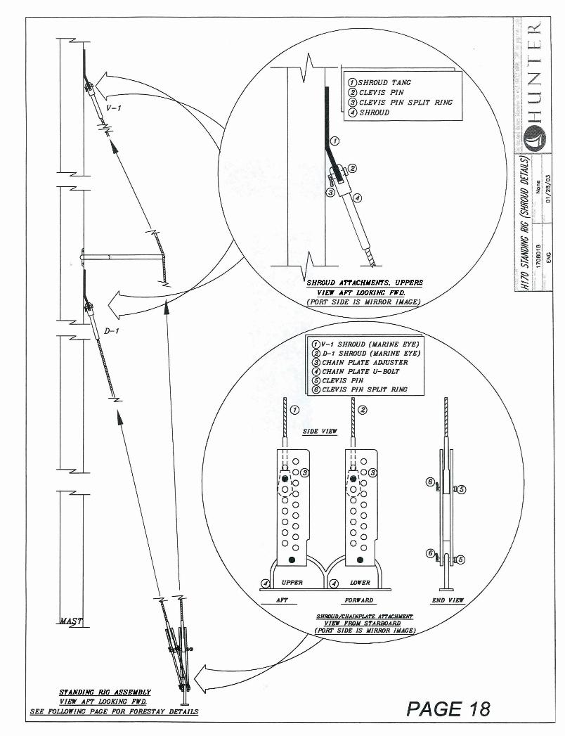
SHROUD ATTACHMENTS. UPPERS VIEW AFT LOOKING FWD.
STANDING RIG ASSEMBLY

UPPER FORESTAY/SHROUD/TOPPING LIFT ATTACHMENT
- @ FORESTAY/SHROUD TANG
@ CLEVIS PIN
@ CLEVIS PIN SPLIT RING
@ FORESTAY PIGTAIL UPPER END = MARINE FORK LOWER END = MARINE EYE
@ UPPER FURLING SWIVEL
@ U P P E R FORESTAY EYE
NOTE: FORESTAY IS INTEGRATED WITHIN THE JIB LUFF
JIB FURLING: 1. J IB IS INSTALLED ROLLED U P
3. LEAD FURLING LINE THRU. "DECK TO COCKPIT CHASE TUBE"
4. THEN THRU JAM CLEAT 5. WHEN JIB I S EXTENDED, FURLING LINE
RETRACTS INTO DRUM . . . . . . . . . . . . . . . . . . . . . . . . . . . . . . . . . . . . . . . .
SIDE VIEW
FRONT VIEW
SIDE VIEW

RIGGING SPECS QTY DESCRIPTION DIAMETER LENGTH
RUNNING RIGGING
1 MAINSHEE T 3/8" (9.5rnm) 28' (2.33m)
I MAIN HALYARD 1/4" (6.4mm) 46' (14.02m)
1 JIB SHEETS 3/8" (9.5rnm) 28' (8.54m)
3 ROLLER FURLING LJNE 7/32" (5.6mm) 15' (4.57m)
I TOPPING LIFT 3/16" (4.8mm) 22' (6.7lm)
1 0 UTHAUL 3/16" (4.8rnrn) 8' (2.44m)
I VANG LINE 1/4" (6.4rnm) 12' (3.66m)
I TACK TIE SUPPLIED WITH JIB SUPPLIED WITH JIB
PAGE 20
QTY DESCRIPTION DlAMETE R LENGTH
I
I
1
1
STANDING RIGGING
VI (VERTICAL) SHROUD
D 1 (DIAGONAL) SHROUD
FORE S A Y PIGTAIL
FORESTAY (INTERGRATED INTO JIB LUFF)
1/8" (3.2mm) 1x19
I/0" (3.2mrn) 1x19
1 / 8 (3.2mrn) 1x39
1/8" (3.2mrn) 1x19
18' 10 1 / 2 (5.817m)
9' 1 5 /B (2.79m)
8 3 / 8 (.214m)
E

_ FORWARD
JAM CLEAT
CENTERBOARD
CENTERBOARD EYE S T R A P MOUNTED AHEAD OF MAINSHEET
k 2nd S S S T R A P
WHEN THE CENTERBOARD I S IN THE DOWN STRAP EYES POSITION, ATTACH THE BUNGEE CORD WITH THE
S N A P HOOKS BETWEEN THESE TWO STRAPS.
NOTE: YOU MUST DETACH PRIOR TO RAISING!
1
CENTERBOARD OPERATIONS:
TO RAISE: PULL CONTROL LINE AFT AND SECURE IN JAM CLEAT.
TO LOWER: RELEASE LINE FROM JAM CLEAT, AND LET DOWN SLOWLY -

f
1. NOTCHED AREA OF CENTERBOARD
2. PIVOT PIN (MOUNTED TO HULL)
3. PLASTIC WASHERS 2 PER BOAT (IEA. SIDE)
4 . PLASTIC SLEEVE (COVERS SCREW)
5. SCREW -
FORWARD
1
L E A D I N G EDGE, DOWN
I
CFNTFRROA Rn IN.qTAI I A TIWlNSTI JCTlnNS'
1. REMOVE THE SCREW AND PLASTIC SLEEVE FWD. LOWER CENTERBOARD.
2. INSERT CENTERBOARD INTO THE TRUNK AND F IT NOTCH I N CENTERBOARD OVER THE PIVOT PIN INSIDE OF THE CENTERBOARD TRUNK. BE SURE THE CENTERBOARD I S I N BETWEEN THE PLASTIC WASHERS ON THE PIVOT PIN.
3. TURN THE BOAT ON ITS SIDE TO INSPECT THE INSTALLATION AND INSTALL THE SECURING SCREW AND THE PLASTIC SLEEVE. THIS WILL ENSURE THE CENTERBOARD I S SECURED ONTO THE PIVOT PIN.
-
SIDE VIEW OF INSTALLED CENTERBOARD