hsupa design libraryedadownload.software.keysight.com/eedl/ads/2011_01/pdf/hsupa.pdf · advanced...
TRANSCRIPT

Advanced Design System 2011.01 - HSUPA Design Library
1
Advanced Design System 2011.01
Feburary 2011HSUPA Design Library

Advanced Design System 2011.01 - HSUPA Design Library
2
© Agilent Technologies, Inc. 2000-20115301 Stevens Creek Blvd., Santa Clara, CA 95052 USANo part of this documentation may be reproduced in any form or by any means (includingelectronic storage and retrieval or translation into a foreign language) without prioragreement and written consent from Agilent Technologies, Inc. as governed by UnitedStates and international copyright laws.
AcknowledgmentsMentor Graphics is a trademark of Mentor Graphics Corporation in the U.S. and othercountries. Mentor products and processes are registered trademarks of Mentor GraphicsCorporation. * Calibre is a trademark of Mentor Graphics Corporation in the US and othercountries. "Microsoft®, Windows®, MS Windows®, Windows NT®, Windows 2000® andWindows Internet Explorer® are U.S. registered trademarks of Microsoft Corporation.Pentium® is a U.S. registered trademark of Intel Corporation. PostScript® and Acrobat®are trademarks of Adobe Systems Incorporated. UNIX® is a registered trademark of theOpen Group. Oracle and Java and registered trademarks of Oracle and/or its affiliates.Other names may be trademarks of their respective owners. SystemC® is a registeredtrademark of Open SystemC Initiative, Inc. in the United States and other countries and isused with permission. MATLAB® is a U.S. registered trademark of The Math Works, Inc..HiSIM2 source code, and all copyrights, trade secrets or other intellectual property rightsin and to the source code in its entirety, is owned by Hiroshima University and STARC.FLEXlm is a trademark of Globetrotter Software, Incorporated. Layout Boolean Engine byKlaas Holwerda, v1.7 http://www.xs4all.nl/~kholwerd/bool.html . FreeType Project,Copyright (c) 1996-1999 by David Turner, Robert Wilhelm, and Werner Lemberg.QuestAgent search engine (c) 2000-2002, JObjects. Motif is a trademark of the OpenSoftware Foundation. Netscape is a trademark of Netscape Communications Corporation.Netscape Portable Runtime (NSPR), Copyright (c) 1998-2003 The Mozilla Organization. Acopy of the Mozilla Public License is at http://www.mozilla.org/MPL/ . FFTW, The FastestFourier Transform in the West, Copyright (c) 1997-1999 Massachusetts Institute ofTechnology. All rights reserved.
The following third-party libraries are used by the NlogN Momentum solver:
"This program includes Metis 4.0, Copyright © 1998, Regents of the University ofMinnesota", http://www.cs.umn.edu/~metis , METIS was written by George Karypis([email protected]).
Intel@ Math Kernel Library, http://www.intel.com/software/products/mkl
SuperLU_MT version 2.0 - Copyright © 2003, The Regents of the University of California,through Lawrence Berkeley National Laboratory (subject to receipt of any requiredapprovals from U.S. Dept. of Energy). All rights reserved. SuperLU Disclaimer: THISSOFTWARE IS PROVIDED BY THE COPYRIGHT HOLDERS AND CONTRIBUTORS "AS IS"AND ANY EXPRESS OR IMPLIED WARRANTIES, INCLUDING, BUT NOT LIMITED TO, THEIMPLIED WARRANTIES OF MERCHANTABILITY AND FITNESS FOR A PARTICULAR PURPOSEARE DISCLAIMED. IN NO EVENT SHALL THE COPYRIGHT OWNER OR CONTRIBUTORS BELIABLE FOR ANY DIRECT, INDIRECT, INCIDENTAL, SPECIAL, EXEMPLARY, ORCONSEQUENTIAL DAMAGES (INCLUDING, BUT NOT LIMITED TO, PROCUREMENT OFSUBSTITUTE GOODS OR SERVICES; LOSS OF USE, DATA, OR PROFITS; OR BUSINESSINTERRUPTION) HOWEVER CAUSED AND ON ANY THEORY OF LIABILITY, WHETHER INCONTRACT, STRICT LIABILITY, OR TORT (INCLUDING NEGLIGENCE OR OTHERWISE)ARISING IN ANY WAY OUT OF THE USE OF THIS SOFTWARE, EVEN IF ADVISED OF THEPOSSIBILITY OF SUCH DAMAGE.
7-zip - 7-Zip Copyright: Copyright (C) 1999-2009 Igor Pavlov. Licenses for files are:

Advanced Design System 2011.01 - HSUPA Design Library
3
7z.dll: GNU LGPL + unRAR restriction, All other files: GNU LGPL. 7-zip License: This libraryis free software; you can redistribute it and/or modify it under the terms of the GNULesser General Public License as published by the Free Software Foundation; eitherversion 2.1 of the License, or (at your option) any later version. This library is distributedin the hope that it will be useful,but WITHOUT ANY WARRANTY; without even the impliedwarranty of MERCHANTABILITY or FITNESS FOR A PARTICULAR PURPOSE. See the GNULesser General Public License for more details. You should have received a copy of theGNU Lesser General Public License along with this library; if not, write to the FreeSoftware Foundation, Inc., 59 Temple Place, Suite 330, Boston, MA 02111-1307 USA.unRAR copyright: The decompression engine for RAR archives was developed using sourcecode of unRAR program.All copyrights to original unRAR code are owned by AlexanderRoshal. unRAR License: The unRAR sources cannot be used to re-create the RARcompression algorithm, which is proprietary. Distribution of modified unRAR sources inseparate form or as a part of other software is permitted, provided that it is clearly statedin the documentation and source comments that the code may not be used to develop aRAR (WinRAR) compatible archiver. 7-zip Availability: http://www.7-zip.org/
AMD Version 2.2 - AMD Notice: The AMD code was modified. Used by permission. AMDcopyright: AMD Version 2.2, Copyright © 2007 by Timothy A. Davis, Patrick R. Amestoy,and Iain S. Duff. All Rights Reserved. AMD License: Your use or distribution of AMD or anymodified version of AMD implies that you agree to this License. This library is freesoftware; you can redistribute it and/or modify it under the terms of the GNU LesserGeneral Public License as published by the Free Software Foundation; either version 2.1 ofthe License, or (at your option) any later version. This library is distributed in the hopethat it will be useful, but WITHOUT ANY WARRANTY; without even the implied warranty ofMERCHANTABILITY or FITNESS FOR A PARTICULAR PURPOSE. See the GNU LesserGeneral Public License for more details. You should have received a copy of the GNULesser General Public License along with this library; if not, write to the Free SoftwareFoundation, Inc., 51 Franklin St, Fifth Floor, Boston, MA 02110-1301 USA Permission ishereby granted to use or copy this program under the terms of the GNU LGPL, providedthat the Copyright, this License, and the Availability of the original version is retained onall copies.User documentation of any code that uses this code or any modified version ofthis code must cite the Copyright, this License, the Availability note, and "Used bypermission." Permission to modify the code and to distribute modified code is granted,provided the Copyright, this License, and the Availability note are retained, and a noticethat the code was modified is included. AMD Availability:http://www.cise.ufl.edu/research/sparse/amd
UMFPACK 5.0.2 - UMFPACK Notice: The UMFPACK code was modified. Used by permission.UMFPACK Copyright: UMFPACK Copyright © 1995-2006 by Timothy A. Davis. All RightsReserved. UMFPACK License: Your use or distribution of UMFPACK or any modified versionof UMFPACK implies that you agree to this License. This library is free software; you canredistribute it and/or modify it under the terms of the GNU Lesser General Public Licenseas published by the Free Software Foundation; either version 2.1 of the License, or (atyour option) any later version. This library is distributed in the hope that it will be useful,but WITHOUT ANY WARRANTY; without even the implied warranty of MERCHANTABILITYor FITNESS FOR A PARTICULAR PURPOSE. See the GNU Lesser General Public License formore details. You should have received a copy of the GNU Lesser General Public Licensealong with this library; if not, write to the Free Software Foundation, Inc., 51 Franklin St,Fifth Floor, Boston, MA 02110-1301 USA Permission is hereby granted to use or copy thisprogram under the terms of the GNU LGPL, provided that the Copyright, this License, andthe Availability of the original version is retained on all copies. User documentation of anycode that uses this code or any modified version of this code must cite the Copyright, thisLicense, the Availability note, and "Used by permission." Permission to modify the codeand to distribute modified code is granted, provided the Copyright, this License, and theAvailability note are retained, and a notice that the code was modified is included.

Advanced Design System 2011.01 - HSUPA Design Library
4
UMFPACK Availability: http://www.cise.ufl.edu/research/sparse/umfpack UMFPACK(including versions 2.2.1 and earlier, in FORTRAN) is available athttp://www.cise.ufl.edu/research/sparse . MA38 is available in the Harwell SubroutineLibrary. This version of UMFPACK includes a modified form of COLAMD Version 2.0,originally released on Jan. 31, 2000, also available athttp://www.cise.ufl.edu/research/sparse . COLAMD V2.0 is also incorporated as a built-infunction in MATLAB version 6.1, by The MathWorks, Inc. http://www.mathworks.com .COLAMD V1.0 appears as a column-preordering in SuperLU (SuperLU is available athttp://www.netlib.org ). UMFPACK v4.0 is a built-in routine in MATLAB 6.5. UMFPACK v4.3is a built-in routine in MATLAB 7.1.
Qt Version 4.6.3 - Qt Notice: The Qt code was modified. Used by permission. Qt copyright:Qt Version 4.6.3, Copyright (c) 2010 by Nokia Corporation. All Rights Reserved. QtLicense: Your use or distribution of Qt or any modified version of Qt implies that you agreeto this License. This library is free software; you can redistribute it and/or modify it undertheterms of the GNU Lesser General Public License as published by the Free SoftwareFoundation; either version 2.1 of the License, or (at your option) any later version. Thislibrary is distributed in the hope that it will be useful,but WITHOUT ANY WARRANTY; without even the implied warranty of MERCHANTABILITYor FITNESS FOR A PARTICULAR PURPOSE. See the GNU Lesser General Public License formore details. You should have received a copy of the GNU Lesser General Public Licensealong with this library; if not, write to the Free Software Foundation, Inc., 51 Franklin St,Fifth Floor, Boston, MA 02110-1301 USA Permission is hereby granted to use or copy thisprogram under the terms of the GNU LGPL, provided that the Copyright, this License, andthe Availability of the original version is retained on all copies.Userdocumentation of any code that uses this code or any modified version of this code mustcite the Copyright, this License, the Availability note, and "Used by permission."Permission to modify the code and to distribute modified code is granted, provided theCopyright, this License, and the Availability note are retained, and a notice that the codewas modified is included. Qt Availability: http://www.qtsoftware.com/downloads PatchesApplied to Qt can be found in the installation at:$HPEESOF_DIR/prod/licenses/thirdparty/qt/patches. You may also contact BrianBuchanan at Agilent Inc. at [email protected] for more information.
The HiSIM_HV source code, and all copyrights, trade secrets or other intellectual propertyrights in and to the source code, is owned by Hiroshima University and/or STARC.
Errata The ADS product may contain references to "HP" or "HPEESOF" such as in filenames and directory names. The business entity formerly known as "HP EEsof" is now partof Agilent Technologies and is known as "Agilent EEsof". To avoid broken functionality andto maintain backward compatibility for our customers, we did not change all the namesand labels that contain "HP" or "HPEESOF" references.
Warranty The material contained in this document is provided "as is", and is subject tobeing changed, without notice, in future editions. Further, to the maximum extentpermitted by applicable law, Agilent disclaims all warranties, either express or implied,with regard to this documentation and any information contained herein, including but notlimited to the implied warranties of merchantability and fitness for a particular purpose.Agilent shall not be liable for errors or for incidental or consequential damages inconnection with the furnishing, use, or performance of this document or of anyinformation contained herein. Should Agilent and the user have a separate writtenagreement with warranty terms covering the material in this document that conflict withthese terms, the warranty terms in the separate agreement shall control.
Technology Licenses The hardware and/or software described in this document are

Advanced Design System 2011.01 - HSUPA Design Library
5
furnished under a license and may be used or copied only in accordance with the terms ofsuch license. Portions of this product include the SystemC software licensed under OpenSource terms, which are available for download at http://systemc.org/ . This software isredistributed by Agilent. The Contributors of the SystemC software provide this software"as is" and offer no warranty of any kind, express or implied, including without limitationwarranties or conditions or title and non-infringement, and implied warranties orconditions merchantability and fitness for a particular purpose. Contributors shall not beliable for any damages of any kind including without limitation direct, indirect, special,incidental and consequential damages, such as lost profits. Any provisions that differ fromthis disclaimer are offered by Agilent only.
Restricted Rights Legend U.S. Government Restricted Rights. Software and technicaldata rights granted to the federal government include only those rights customarilyprovided to end user customers. Agilent provides this customary commercial license inSoftware and technical data pursuant to FAR 12.211 (Technical Data) and 12.212(Computer Software) and, for the Department of Defense, DFARS 252.227-7015(Technical Data - Commercial Items) and DFARS 227.7202-3 (Rights in CommercialComputer Software or Computer Software Documentation).

Advanced Design System 2011.01 - HSUPA Design Library
6
About the HSUPA Design Library . . . . . . . . . . . . . . . . . . . . . . . . . . . . . . . . . . . . . . . . . . . . . 8 3GPP Technical Specifications Supported . . . . . . . . . . . . . . . . . . . . . . . . . . . . . . . . . . . . . . 9 HSUPA Systems . . . . . . . . . . . . . . . . . . . . . . . . . . . . . . . . . . . . . . . . . . . . . . . . . . . . . . . 10 Specifications for E-DCH and E-DPDCH . . . . . . . . . . . . . . . . . . . . . . . . . . . . . . . . . . . . . . . 11 HSUPA Component Libraries Overview . . . . . . . . . . . . . . . . . . . . . . . . . . . . . . . . . . . . . . . . 12 Design Examples . . . . . . . . . . . . . . . . . . . . . . . . . . . . . . . . . . . . . . . . . . . . . . . . . . . . . . . 13 Glossary of Terms . . . . . . . . . . . . . . . . . . . . . . . . . . . . . . . . . . . . . . . . . . . . . . . . . . . . . . 14
HSUPA Base Station Receiver Design Examples . . . . . . . . . . . . . . . . . . . . . . . . . . . . . . . . . . . 15 Demodulation Performance Measurements . . . . . . . . . . . . . . . . . . . . . . . . . . . . . . . . . . . . . 16 Signaling Detection Performance Measurements - False Alarm . . . . . . . . . . . . . . . . . . . . . . . 20 Signaling Detection Performance Measurements - Missed Detection . . . . . . . . . . . . . . . . . . . 22
HSUPA Components . . . . . . . . . . . . . . . . . . . . . . . . . . . . . . . . . . . . . . . . . . . . . . . . . . . . . . 24 Contents . . . . . . . . . . . . . . . . . . . . . . . . . . . . . . . . . . . . . . . . . . . . . . . . . . . . . . . . . . . . 25 HSPA_Channel . . . . . . . . . . . . . . . . . . . . . . . . . . . . . . . . . . . . . . . . . . . . . . . . . . . . . . . . 26 HSUPA_BER_Throughput . . . . . . . . . . . . . . . . . . . . . . . . . . . . . . . . . . . . . . . . . . . . . . . . . 29 HSUPA_Bits . . . . . . . . . . . . . . . . . . . . . . . . . . . . . . . . . . . . . . . . . . . . . . . . . . . . . . . . . . 31 HSUPA_ChDecode . . . . . . . . . . . . . . . . . . . . . . . . . . . . . . . . . . . . . . . . . . . . . . . . . . . . . . 33 HSUPA_ChEncode . . . . . . . . . . . . . . . . . . . . . . . . . . . . . . . . . . . . . . . . . . . . . . . . . . . . . . 35 HSUPA_CodeBlkDeseg . . . . . . . . . . . . . . . . . . . . . . . . . . . . . . . . . . . . . . . . . . . . . . . . . . . 36 HSUPA_CodeBlkSeg . . . . . . . . . . . . . . . . . . . . . . . . . . . . . . . . . . . . . . . . . . . . . . . . . . . . . 37 HSUPA_Deinterleaver . . . . . . . . . . . . . . . . . . . . . . . . . . . . . . . . . . . . . . . . . . . . . . . . . . . 38 HSUPA_DL_Rake . . . . . . . . . . . . . . . . . . . . . . . . . . . . . . . . . . . . . . . . . . . . . . . . . . . . . . . 39 HSUPA_DL_Receiver . . . . . . . . . . . . . . . . . . . . . . . . . . . . . . . . . . . . . . . . . . . . . . . . . . . . 42 HSUPA_DL_ReceiverRF . . . . . . . . . . . . . . . . . . . . . . . . . . . . . . . . . . . . . . . . . . . . . . . . . . 46 HSUPA_DL_Source . . . . . . . . . . . . . . . . . . . . . . . . . . . . . . . . . . . . . . . . . . . . . . . . . . . . . 50 HSUPA_DL_SourceRF . . . . . . . . . . . . . . . . . . . . . . . . . . . . . . . . . . . . . . . . . . . . . . . . . . . . 55 HSUPA_EAGCH . . . . . . . . . . . . . . . . . . . . . . . . . . . . . . . . . . . . . . . . . . . . . . . . . . . . . . . . 61 HSUPA_EAGCH_Decode . . . . . . . . . . . . . . . . . . . . . . . . . . . . . . . . . . . . . . . . . . . . . . . . . . 63 HSUPA_EAGCH_DeRM . . . . . . . . . . . . . . . . . . . . . . . . . . . . . . . . . . . . . . . . . . . . . . . . . . . 65 HSUPA_EAGCH_RM . . . . . . . . . . . . . . . . . . . . . . . . . . . . . . . . . . . . . . . . . . . . . . . . . . . . . 66 HSUPA_EDPCCH_ChDecode . . . . . . . . . . . . . . . . . . . . . . . . . . . . . . . . . . . . . . . . . . . . . . . 67 HSUPA_EDPCCH_ChEncode . . . . . . . . . . . . . . . . . . . . . . . . . . . . . . . . . . . . . . . . . . . . . . . 69 HSUPA_EHICH_ERGCH . . . . . . . . . . . . . . . . . . . . . . . . . . . . . . . . . . . . . . . . . . . . . . . . . . . 70 HSUPA_EHICH_ERGCH_Decode . . . . . . . . . . . . . . . . . . . . . . . . . . . . . . . . . . . . . . . . . . . . 72 HSUPA_EVM . . . . . . . . . . . . . . . . . . . . . . . . . . . . . . . . . . . . . . . . . . . . . . . . . . . . . . . . . . 74 HSUPA_EVM_Old . . . . . . . . . . . . . . . . . . . . . . . . . . . . . . . . . . . . . . . . . . . . . . . . . . . . . . . 78 HSUPA_FRC . . . . . . . . . . . . . . . . . . . . . . . . . . . . . . . . . . . . . . . . . . . . . . . . . . . . . . . . . . 80 HSUPA_FRC_Receiver . . . . . . . . . . . . . . . . . . . . . . . . . . . . . . . . . . . . . . . . . . . . . . . . . . . 82 HSUPA_FRC_ReceiverRF . . . . . . . . . . . . . . . . . . . . . . . . . . . . . . . . . . . . . . . . . . . . . . . . . . 85 HSUPA_FRC_RF . . . . . . . . . . . . . . . . . . . . . . . . . . . . . . . . . . . . . . . . . . . . . . . . . . . . . . . . 88 HSUPA_Interleaver . . . . . . . . . . . . . . . . . . . . . . . . . . . . . . . . . . . . . . . . . . . . . . . . . . . . . 91 HSUPA_OCNS . . . . . . . . . . . . . . . . . . . . . . . . . . . . . . . . . . . . . . . . . . . . . . . . . . . . . . . . . 93 HSUPA_ParamCalc . . . . . . . . . . . . . . . . . . . . . . . . . . . . . . . . . . . . . . . . . . . . . . . . . . . . . . 95 HSUPA_PhCH_Demap . . . . . . . . . . . . . . . . . . . . . . . . . . . . . . . . . . . . . . . . . . . . . . . . . . . 99 HSUPA_PhCH_Map . . . . . . . . . . . . . . . . . . . . . . . . . . . . . . . . . . . . . . . . . . . . . . . . . . . . . 101 HSUPA_RateDematch . . . . . . . . . . . . . . . . . . . . . . . . . . . . . . . . . . . . . . . . . . . . . . . . . . . 103 HSUPA_RateMatch . . . . . . . . . . . . . . . . . . . . . . . . . . . . . . . . . . . . . . . . . . . . . . . . . . . . . . 105 HSUPA_RF_EVM . . . . . . . . . . . . . . . . . . . . . . . . . . . . . . . . . . . . . . . . . . . . . . . . . . . . . . . 107 HSUPA_RF_OutputPower . . . . . . . . . . . . . . . . . . . . . . . . . . . . . . . . . . . . . . . . . . . . . . . . . 109 HSUPA_SignatureSqn . . . . . . . . . . . . . . . . . . . . . . . . . . . . . . . . . . . . . . . . . . . . . . . . . . . 111 HSUPA_Spread . . . . . . . . . . . . . . . . . . . . . . . . . . . . . . . . . . . . . . . . . . . . . . . . . . . . . . . . 116 HSUPA_UL_Rake . . . . . . . . . . . . . . . . . . . . . . . . . . . . . . . . . . . . . . . . . . . . . . . . . . . . . . . 119 HSUPA_UL_Source . . . . . . . . . . . . . . . . . . . . . . . . . . . . . . . . . . . . . . . . . . . . . . . . . . . . . 125 HSUPA_UL_SourceRF . . . . . . . . . . . . . . . . . . . . . . . . . . . . . . . . . . . . . . . . . . . . . . . . . . . . 128
HSUPA User Equipment Receiver Design Examples . . . . . . . . . . . . . . . . . . . . . . . . . . . . . . . . . 131 E-AGCH Demodulation Performance Measurements . . . . . . . . . . . . . . . . . . . . . . . . . . . . . . . 132

Advanced Design System 2011.01 - HSUPA Design Library
7
E-HICH Detection Performance Measurements . . . . . . . . . . . . . . . . . . . . . . . . . . . . . . . . . . 134 E-RGCH Detection Performance Measurements . . . . . . . . . . . . . . . . . . . . . . . . . . . . . . . . . . 136
HSUPA User Equipment Transmitter Design Examples . . . . . . . . . . . . . . . . . . . . . . . . . . . . . . . 138 Adjacent Channel Leakage Power Ratio Measurements . . . . . . . . . . . . . . . . . . . . . . . . . . . . 139 CCDF and Peak-to-Mean Information Measurements . . . . . . . . . . . . . . . . . . . . . . . . . . . . . . 141 Error Vector Magnitude Measurements . . . . . . . . . . . . . . . . . . . . . . . . . . . . . . . . . . . . . . . . 143 Maximum Power Measurements . . . . . . . . . . . . . . . . . . . . . . . . . . . . . . . . . . . . . . . . . . . . 145 Spectrum Emission Mask Measurements . . . . . . . . . . . . . . . . . . . . . . . . . . . . . . . . . . . . . . 147

Advanced Design System 2011.01 - HSUPA Design Library
8
About the HSUPA Design LibraryThe HSUPA Design Library is designed for 3GPP FDD enhanced uplink, also known asHSUPA, defined in release 6 of 3GPP specification. This design library focuses on thephysical layer aspects of HSUPA systems and is intended to be a baseline system fordesigners to get an idea of what nominal or ideal system performance would be.Evaluations can be made regarding degraded system performance due to systemimpairments that may include non-ideal component performance.
The transport channels and physical channels defined in release 5 and previous versions of3GPP specification such as DCH, DPDCH are also supported by HSUPA design library. Butthey are treated as the accessory channels because HSUPA design library focus on themodeling and test of channels defined in release 6, say HSUPA. The test for the scenariowith only 3GPP FDD with/without HSDPA can be implemented by 3GPP design library.

Advanced Design System 2011.01 - HSUPA Design Library
9
3GPP Technical Specifications Supported3GPP committee updates 3GPP technical specifications every 3 months. Each of 3GPPspecification is further classified by features: release '99 (Version 3.x.x), release 4(Version 4.x.x), release 5 (Version 5.x.x), release 6 (Version 6.x.x) release 7(Version7.x.x). Basically, the contents defined in lower version specifications duplicate thecontents from release '99, release 4 and release 5 that are published simultaneously.
The HSUPA design library is compliant with 3GPP release 6 technical specificationspublished in 2006-03.
HSUPA design library also reuses some 3GPP design library models in the application level.The technical specifications of those models were published in 2002-03 for release '99content and 2003-09 for HSDPA part in release 5. The version may be changed if 3GPPdesign library is updated.

Advanced Design System 2011.01 - HSUPA Design Library
10
HSUPA SystemsHSUPA aims at providing significant enhancements in terms of user experience(throughput and delay) and/or capacity. It enables you to achieve significantimprovements in overall system performance when operated together with HSDPA. Inother words, the aim of HSUPA is to enhance the uplink DCH operation and performanceto support services like video-clips, multimedia, e-mail, telematics, gaming, video-streaming, and etc. At the same time, HSUPA is backward-compatible with 3GPP FDD withHSDPA defined in release 5 and previous versions of 3GPP specification.
In the uplink, two new physical channels E-DPDCH and E-DPCCH are defined.The HSUPA uplink transmitter and receiver structure block diagram for E-DPDCH isshown below:
In HSUPA downlink, three new channels E-AGCH, E-HICH and E-RGCH are defined. TheHSUPA downlink physical layer structure is almost the same as 3GPP FDD with HSDPAdefined in release 5 and previous released versions. All downlink physical channelsincluding three new channels are spread, QPSK-mapped and scrambled separately andthen combined as the downlink signal. The structure of downlink transmitter and receivercan be found in 3GPP design library.

Advanced Design System 2011.01 - HSUPA Design Library
11
Specifications for E-DCH and E-DPDCHHSUPA E-DCH physical layer categories are shown in the FDD E-DCH physical layercategories table below:E-DCHcategory
Maximumnumber of E-DPDCHtransmitted
Minimumspreadingfactor of E-DPDCH
Supportfor 10 and2 ms TTIE-DCH
Maximum numberof bits of an E-DCHtransport blocktransmitted withina 10 ms E-DCH TTI
Maximum numberof bits of an E-DCHtransport blocktransmitted withina 2 ms E-DCH TTI
Category1
1 SF4 10 ms TTIonly
7110 -
Category2
2 SF4 10 ms and2 ms TTI
14484 2798
Category3
2 SF4 10 ms TTIonly
14484 -
Category4
2 SF2 10 ms and2 ms TTI
20000 5772
Category5
2 SF2 10 ms TTIonly
20000 -
Category6
4 SF2 10 ms and2 ms TTI
20000 11484
Category7
4 SF2 10 ms and2 ms TTI
20000 22996
NOTE: When 4 codes are transmitted in parallel, two codes shall be transmitted with SF2 and two withSF4
The physical channel parameters on E-DPDCH for E-DCH test are shown in thetable below:TTI Number of processes
2 ms 8
10 ms 4
Advanced Design System 2011.01 - HSUPA Design Library
12
HSUPA Component Libraries OverviewThe HSUPA Library is categorized as below:Channel Components:
Multipath fading channel
Channel Coding Components:
Turbo code as E-DCH forward error control codeRevised TFCI Reed-Muller (RM) coding as E-DPCCH channel coding and signal qualityindicatorOrthogonal signature sequence as E-HICH/E-RGCH channel coding and signal qualityindicatorRate match (puncturing and repetition) used to implement channel coding withflexible coding rate for E-DCH and E-AGCHInterleaving used to spread burst errors into random errors in order to improve theerror correction code performance
Multiplex Components:
Code segmentation used to adjust code block to suitable sizePhysical channel mapping used to map E-DCH to E-DPDCHUplink spreader used to spread, power-scale and multiplex various uplink channels
Measurement Components :
Throughput, BER and PER vs. retransmission time measurementOutput power measurement as well as cubic metric calculatorEVM and phase discontinuity measurements
Receiver Components:
Rake receivers for HSUPA uplink and downlinkBaseband receivers for HSUPA uplink and downlinkRF receiver for HSUPA uplink and downlink Base Station and User EquipmentComponents
Signal Source Components:
E-DCH information bit source which support HARQ processUplink fixed reference channel in baseband and RFUplink general signal source in baseband and RFDownlink signal source for E-AGCH and E-HICH/E-RGCHDownlink general signal source in baseband and RF

Advanced Design System 2011.01 - HSUPA Design Library
13
Design ExamplesThe RF characteristics can be measured using the HSUPA design library. RF measurementsfor user equipment (UE) are defined in Reference [5]; test methods are described inReference [8]. For base station (BS), the RF characteristics are defined in Reference [6];test methods are described in Reference [7].
The HSUPA_BS_Rx_wrk workspace shows base station receiver performance on E-DCH. Designs for these measurements include:
E-DPDCH demodulation performance: BS_Rx_DemodulationE-DPDCH demodulation performance in fading channel:BS_Rx_DemodulationFadingE-DPCCH missed detection: BS_Rx_MissedDetectionE-DPCCH missed detection in fading channel: BS_Rx_MissedDetectionFadingE-DPCCH false alarm: BS_Rx_FalseAlarmE-DPCCH false alarm in fading channel: BS_Rx_FalseAlarmFading
The HSUPA_UE_Rx_wrk workspace shows HSUPA user equipment receiverperformance. Designs for these measurements include:
E-AGCH demodulation performance: UE_Rx_EAGCH_DemodulationE-AGCH demodulation performance in fading channel:UE_Rx_EAGCH_DemodulationFadingE-HICH detection performance: UE_Rx_EHICH_DetectionE-HICH detection performance in fading channel:UE_Rx_EHICH_DetectionFadingE-RGCH detection performance: UE_Rx_ERGCH_DetectionE-RGCH detection performance in fading channel:UE_Rx_ERGCH_DetectionFading
The HSUPA_UE_Tx_wrk workspace demonstrates user equipment transmittermeasurement characteristics. Designs for these measurements include:
Adjacent channel leakage power ratio measurements: UE_Tx_ACLRCCDF and peak-to-mean information measurements: UE_Tx_CCDFError vector magnitude and phase discontinuity measurements: UE_Tx_EVMMaximum power measurements: UE_Tx_Max_PowerSpectrum emission measurements: UE_Tx_SpecEmissions
The HSUPA_RF_Verification_wrk workspace has only one WTB-like design:HSUPA_UE_TX_test

Advanced Design System 2011.01 - HSUPA Design Library
14
Glossary of Terms
3GPP third generation partnership project
ACLR adjacent channel leakage power ratio
AWGN additive white Gaussian noise
CCDF complementary cumulative distribution function
DCH dedicated channel
DPDCH dedicated physical data channel
E-AGCH E-DCH absolute grant channel
E-DCH enhanced DCH
E-DPCCH E-DCH HARQ acknowledgement indicator channel
E-DPDCH
E-DCH relative grant channel
E-HICH E-DCH dedicated physical control channel
E-RGCH E-DCH dedicated physical data channel
EVM error vector magnitude
FDD frequency division duplex
FEC forward error correction
HSDPA high speed downlink packet access
HSUPA high speed uplink packet access
PA power amplifier
PER packet error rate
QPSK quadrature phase shift keying
RF radio frequency
RX receive or receiver
TTI transmission timing interval
TX transmit or transmitter
References
3GPP Technical Specification TS 25.211, "Physical channels and mapping of transport1.channels onto physical channels (FDD)," Version 7.10.0, May 2008.3GPP Technical Specification TS 25.212, "Multiplexing and channel coding (FDD),"2.Version 7.9.0, Sept. 2008.3GPP Technical Specification TS 25.213, "Spreading and modulation (FDD)," Version3.7.6.0, Sept. 2008.3GPP Technical Specification TS 25.214, "Physical layer procedures (FDD)," Version4.7.9.0, May 2008.3GPP Technical Specification TS 25.101, "UE Radio transmission and Reception5.(FDD)," Version 7.13.0, Sept. 2008.3GPP Technical Specification TS 25.104, "UTRA (BS) FDD: Radio transmission and6.Reception," Version 7.10.0, Mar. 2008.3GPP Technical Specification TS 25.141, "Base station conformance test," Version7.7.11.0, Mar. 2008.3GPP Technical Specification TS 34.121, "Radio transmission and reception (FDD),"8.Version 7.5.0, June 2007.3GPP Technical Specification TS 25.306, "UE Radio Access capabilities," Version9.7.8.0, Sept. 2008.3GPP Technical Specification TS 25.321, "Medium Access Control (MAC) protocol10.specification". Version 7.7.0, Dec. 2008.

Advanced Design System 2011.01 - HSUPA Design Library
15
HSUPA Base Station Receiver DesignExamplesThe HSUPA_BS_Rx_wrk workspace shows base station receiver measurementperformances, including E-DPDCH demodulation performance, E-DPCCH signaling falsealarm performance, and E-DPCCH signaling missed detection performance.
Designs for these measurements are described in the following sections; they include:
Demodulation performance:BS_Rx_DemodulationBS_Rx_DemodulationFading
Signaling detection performance - false alarm:BS_RX_FalseAlarmBS_RX_FalseAlarmFading
Signaling detection performance - missed detection:BS_RX_MissedDetectionBS_RX_MissedDetectionFading
Designs under this workspace consist of:
Uplink RF band signal source: HSUPA_FRC_RF is used to provide an RF HSUPA uplinksignal source.Fading channel: HSPA_Channel is used to provide various multi-path fadingpropagation conditions.AWGN noise: AddNDensity is used to provide AWGN in order to calibrate the systemE c /N 0 at certain levels, which are required by various performance measurements.
Base station RF receiver: HSUPA_FRC_ReceiverRF is used to provide a receiver of RFHSUPA uplink signals.

Advanced Design System 2011.01 - HSUPA Design Library
16
Demodulation Performance MeasurementsDesign: BS_Rx_DemodulationFading, BS_Rx_Demodulation, BS_RX_Demodulation_FRC8
Features:
Base station receiver demodulation performance measurementsUplink fixed reference channel (FRC) and receiverARQ (feedback) controlled sourceIntegrated RF modelsThroughput (R)Multiple E c /N 0 measurement points
Multi-path fading propagation conditions
Description:
BS_Rx_DemodulationFading measures base station receiver E-DPDCH demodulationperformance according to section 8.11 in TS 25.104.BS_Rx_Demodulation measures base station receiver E-DPDCH demodulationperformance over AWGN condition to provide the baseline reference.BS_Rx_DemodulationFading_FRC8 measures base station receiver E-DPDCHdemodulation performance according to section 8.11 in TS 25.104.
The schematics of fading and AWGN conditions are shown in BS_Rx_DemodulationFadingSchematic and BS_Rx_Demodulation Schematic respectively.
BS_Rx_DemodulationFading Schematic
BS_Rx_Demodulation Schematic

Advanced Design System 2011.01 - HSUPA Design Library
17
BS_Rx_DemodulationFading_FRC8 Schematic
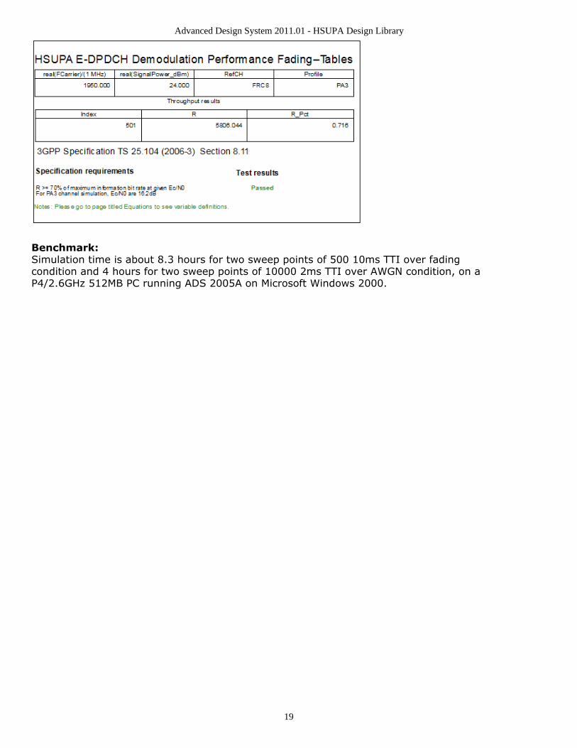
Simulation Results:Simulation results are shown in Throughput Results (R) for Base Station DemodulationPerformance Measurement (Fading) and Throughput Results (R) for Base StationDemodulation Performance Measurement (AWGN).
Throughput Results (R) for Base Station Demodulation Performance Measurement (Fading)

Advanced Design System 2011.01 - HSUPA Design Library
18
Throughput Results (R) for Base Station Demodulation Performance Measurement (AWGN)
Throughput Results (R) for Base Station Demodulation Performance Measurement (Fading) for FRC8
Advanced Design System 2011.01 - HSUPA Design Library
19
Benchmark:Simulation time is about 8.3 hours for two sweep points of 500 10ms TTI over fadingcondition and 4 hours for two sweep points of 10000 2ms TTI over AWGN condition, on aP4/2.6GHz 512MB PC running ADS 2005A on Microsoft Windows 2000.

Advanced Design System 2011.01 - HSUPA Design Library
20
Signaling Detection Performance Measurements -False AlarmDesign: BS_RX_FalseAlarmFading, BS_RX_FalseAlarm
Features:
Base station receiver E-DPCCH signaling detection performance measurementsUplink fixed reference channel (FRC) and receiverIntegrated RF modelsMulti-path fading propagation conditions
Description:
BS_RX_FalseAlarmFading measures base station receiver E-DPCCH signaling falsealarm performance according to section 8.12 in TS 25.104.BS_RX_FalseAlarm measures base station receiver E-DPCCH signaling false alarmperformance over AWGN condition to provide the baseline reference.
The schematics for BS_RX_FalseAlarmFading and BS_RX_FalseAlarm are shown inBS_RX_FalseAlarmFading Schematic and BS_RX_FalseAlarm Schematic respectively.
BS_RX_FalseAlarmFading Schematic
BS_RX_FalseAlarm Schematic
Simulation Results:

Advanced Design System 2011.01 - HSUPA Design Library
21
Simulation results are shown in False Alarm Results for Base Station Signaling DetectionPerformance Measurements (Fading) and False Alarm Results for Base Station SignalingDetection Performance Measurements (AWGN).
False Alarm Results for Base Station Signaling Detection Performance Measurements (Fading)
False Alarm Results for Base Station Signaling Detection Performance Measurements (AWGN)
Benchmark:Simulation time is about 14.7 hours for 5000 2ms TTI over fading (PB3) condition and 1.5hours for 10000 2ms TTI over AWGN condition, on a P4/2.6GHz 512MB PC running ADS2005A on Microsoft Windows 2000.

Advanced Design System 2011.01 - HSUPA Design Library
22
Signaling Detection Performance Measurements -Missed DetectionDesign: BS_RX_MissedDetectionFading, BS_RX_MissedDetection
Features:
Base station receiver E-DPCCH signaling detection performance measurementsUplink fixed reference channel (FRC) and receiverIntegrated RF modelsMulti-path fading propagation conditions
Description:
BS_RX_MissedDetectionFading measures base station receiver E-DPCCH signalingmissed detection performance according to section 8.12 in TS 25.104.BS_RX_MissedDetection measures base station receiver E-DPCCH signaling misseddetection performance over AWGN condition to provide the baseline reference.
The schematics for fading and AWGN conditions are shown inBS_RX_MissedDetectionFading Schematic and BS_RX_MissedDetection Schematicrespectively.
BS_RX_MissedDetectionFading Schematic
BS_RX_MissedDetection Schematic

Advanced Design System 2011.01 - HSUPA Design Library
23
Simulation Results:Simulation results are shown in Missed Detection Results for Base Station SignalingDetection Performance Measurements (Fading) and Missed Detection Results for BaseStation Signaling Detection Performance Measurements (AWGN).
Missed Detection Results for Base Station Signaling Detection Performance Measurements (Fading)
Missed Detection Results for Base Station Signaling Detection Performance Measurements (AWGN)
Benchmark:Simulation time is about 15.5 hours for 5000 2ms TTI over fading (PB3) condition and 1.5hours for 10000 2ms TTI over AWGN condition, on a P4/2.6GHz 512MB PC running ADS2005A on Microsoft Windows 2000.
References
3GPP Technical Specification TS 25.104, "UTRA (BS) FDD: Radio transmission and1.Reception," Version 7.10.0, Mar. 2008.

Advanced Design System 2011.01 - HSUPA Design Library
24
HSUPA Components

Advanced Design System 2011.01 - HSUPA Design Library
25
ContentsHSUPA Bits (hsupa)HSUPA ChEncode (hsupa)HSUPA CodeBlkSeg (hsupa)HSUPA DL Source (hsupa)HSUPA DL SourceRF (hsupa)HSUPA EAGCH (hsupa)HSUPA EAGCH RM (hsupa)HSUPA EDPCCH ChEncode (hsupa)HSUPA EHICH ERGCH (hsupa)HSUPA EVM (hsupa)HSUPA EVM Old (hsupa)HSUPA FRC (hsupa)HSUPA FRC RF (hsupa)HSUPA Interleaver (hsupa)HSUPA OCNS (hsupa)HSUPA ParamCalc (hsupa)HSUPA PhCH Map (hsupa)HSUPA RateMatch (hsupa)HSUPA RF EVM (hsupa)HSUPA RF OutputPower (hsupa)HSUPA SignatureSqn (hsupa)HSUPA Spread (hsupa)HSUPA UL Source (hsupa)HSUPA UL SourceRF (hsupa)HSPA Channel (hsupa)HSUPA BER Throughput (hsupa)HSUPA ChDecode (hsupa)HSUPA CodeBlkDeseg (hsupa)HSUPA Deinterleaver (hsupa)HSUPA DL Rake (hsupa)HSUPA DL Receiver (hsupa)HSUPA DL ReceiverRF (hsupa)HSUPA EAGCH Decode (hsupa)HSUPA EAGCH DeRM (hsupa)HSUPA EDPCCH ChDecode (hsupa)HSUPA EHICH ERGCH Decode (hsupa)HSUPA FRC Receiver (hsupa)HSUPA FRC ReceiverRF (hsupa)HSUPA PhCH Demap (hsupa)HSUPA RateDematch (hsupa)HSUPA UL Rake (hsupa)

Advanced Design System 2011.01 - HSUPA Design Library
26
HSPA_Channel
Description: HSPA fading channel modelLibrary: HSUPA, Channel
Parameters
Name Description Default Unit Type Range
RIn Input resistance DefaultRIn Ohm real (0,∞)
ROut Output resistance DefaultROut Ohm real (0,∞)
FreqBand Frequency band: Band I II III IV, Band V VI Band I II IIIIV
enum
ChProfile Channel profile: PA3, PB3, VA30, VA120, Case 8 forHSDPA CQI Test
VA30 enum
VelocitySetting Velocity setting: Follow ChProfile, User defined FollowChProfile
enum
Velocity Mobile velocity in km/hour 30 real [1,500]
PathLoss Option for inclusion of large-scale pathloss: NO, YES NO enum
PropDistance Propagation distance 2000 m real [500,5000]
Pin Inputs
Pin Name Description Signal Type
1 input channel inputsignal
timed
Pin Outputs
Pin Name Description Signal Type
2 output output signal timed
3 outChM fading factor multiple complex
Notes/Equations
This subnetwork is the fading channel emulator.1.Each firing, 1 output token and 1 outChM token are generated when 1 input token is2.consumed.The input signal is fed into a multipath Rayleigh fading channel based on a tapped-3.delay line model.The Doppler spectrum is classic. The way to generate the classic Doppler spectrum is4.to pass AWGN noise through a shaping filter. This filter is identical with the one usedin CDMA2K_ClassicSpec which is available in CDMA2K design library.Fading channel profiles defined for HSUPA and HSDPA in [4] and [5] are supported.5.The mobile speed, relative channel delay spread and average power are given in thetables below:
Propagation Conditions for Multi-Path Fading Environments for HSDPA and HSUPA Performance Requirements(Pedestrian Speed)

Advanced Design System 2011.01 - HSUPA Design Library
27
ITU Pedestrian A Speed 3 km/h (PA3) ITU Pedestrian B Speed 3 km/h (PB3)
Speed for Band I, II, III and IV3 km/h Speed for Band I, II, III and IV3 km/h
Speed for Band V, VI7 km/h Speed for Band V, VI7 km/h
RelativeDelay[ns] Relative MeanPower[dB] RelativeDelay[ns] Relative MeanPower[dB]
0 0 0 0
110 -9.7 200 -0.9
190 -19.2 800 -4.9
410 -22.8 1200 -8.0
2300 -7.8
3700 -23.9 Propagation Conditions for Multi-Path Fading Environments for HSDPA and HSUPA Performance Requirements(Vehicular Speed)
ITU vehicular A Speed 30 km/h (VA30) ITU vehicular A Speed 120 km/h (VA120)
Speed for Band I, II, III and IV30 km/h Speed for Band I, II, III and IV120 km/h
Speed for Band V, VI71 km/h Speed for Band V, VI282 km/h†
RelativeDelay[ns] Relative MeanPower[dB] RelativeDelay[ns] Relative MeanPower[dB]
0 0 0 0
310 -1.0 310 -1.0
710 -9.0 710 -9.0
1090 -10.0 1090 -10.0
1730 -15.0 1730 -15.0
2510 -20.0 2510 -20.0
† Speed above 120 km/h is applicable to demodulation performance requirements only. Propagation Conditions for CQI test in multi-path fading
Case 8, speed 30 km/h
Relative Delay [ns] Relative mean Power [dB]
0 0
976 -10
Users can also customize the speed of each channel profile as explained below:6.Set VelocitySetting = User defined.Set Velocity to the target speed.
If the input time step is too large, interpolation will be performed to up-sample the7.signal so that the resulted time step will be less than 1 nsec. Simulation time in thecase of a large interpolation rate would increase; in other cases when the delay for apath is larger, the signals to be buffered and interpolated would increase which wouldlead to increased simulation time.Path loss is calculated according to [3], when PathLoss set to YES.8.
For ITU PA3 and PB3, pass loss is L=40 log 10 R+30 log 10 f + 49;
For ITU VA30, VA120, pass loss is L=40 (1 - 4×10 -3 Δh b) log 10 R - 18 log 10Δhb hb+21 log 10 f + 80 dB where:
R: base station – mobile station separation (km), which can be set usingparameter PropDistancef: carrier frequency (MHz)Δh b: base station antenna height (m), measured from the average rooftop
level. Δh b is fixed at 15m.

Advanced Design System 2011.01 - HSUPA Design Library
28
References
3GPP Technical Specification TS 25.104, "UTRA (BS) FDD: Radio transmission and1.Reception," Version 6.12.0, Mar. 2006.3GPP Technical Specification TS 25.101, "UE Radio transmission and Reception2.(FDD)," Version 6.11.0, Mar. 2006.Recommendation ITU-R M.1225, Guidelines for evaluation of radio transmission3.technologies for IMT-2000, 1997.

Advanced Design System 2011.01 - HSUPA Design Library
29
HSUPA_BER_Throughput
Description: EDCH BER and throughput calculatorLibrary: HSUPA, Measurement
Parameters
Name Description Default Symbol Type Range
EDCH_Category FDD E-DCH physical layer categories: Category1, Category 2, Category 3, Category 4,Category 5, Category 6, Category 7
Category6
enum
TransBlockSize Transport block size 2706 L int [1,maxtransport blocksize]†
TTI Transmission time interval: TTI 2ms, TTI 10ms TTI 2ms enum
MaxRSN Maximum retransmission sequence number 3 int [0,3]
TransBlockIgnored Transport block Ignored due to system delay 1 int [0,5]
† Please refer to table of FDD E-DCH physical layer categories.
Pin Inputs
Pin Name Description Signal Type
1 Rcvd received bits int
2 Parity CRC result of received bits int
3 RSN retransmission sequencenumber
int
4 Ref reference bits int
Pin Outputs
Pin Name Description Signal Type
5 R throughput in kbps real
6 R_Pct throughput inpercent
real
7 BER bit error rate real
8 PER packet error rate real
Notes/Equations
This model is used to estimate throughput as well as BER/PER vs. retransmission1.time of HSUPA uplink.Each firing, MaxRSN+1 BER and PER tokens, one R and R_Pct tokens are produced2.when TransBlockSize Rcvd and Ref tokens, one parity token and one RSN tokenconsumed.All the input pins are optional. But at any time either pin parity or both pin Rcvd and3.Ref must be connected. If parity is connected, throughput is estimated. If pin Rcvdand Ref are connected, BER/PER is calculated.When BER/PER is calculated, if RSN is connected, BER/PER vs. retransmission is4.calculated; if RSN is not connected, retransmission is not taken into account. That is,
Advanced Design System 2011.01 - HSUPA Design Library
30
in this way this model can be used as common BER/FER calculator.R_Pct is number of packet with Parity 1 divided by the total number of Parity5.received. R is R_Pct multiplied by information bit rate.
References
3GPP Technical Specification TS 25.211, "Physical channels and mapping of transport1.channels onto physical channels (FDD)," Version 6.7.0, Dec. 2005.3GPP Technical Specification TS 25.212, "Multiplexing and channel coding (FDD),"2.Version 6.7.0, Dec. 2005.3GPP Technical Specification TS 25.213, "Spreading and modulation (FDD)," Version3.6.5.0, Mar. 2006.3GPP Technical Specification TS 25.104, "UTRA (BS) FDD: Radio transmission and4.Reception," Version 6.12.0, Mar. 2006.3GPP Technical Specification TS 25.141, "Base station conformance test," Version5.6.13.0, Mar. 2006.

Advanced Design System 2011.01 - HSUPA Design Library
31
HSUPA_Bits
Description: HSUPA information bit generatorLibrary: HSUPA, Signal Sources
Parameters
Name Description Default Symbol Type Range
EDCH_Category FDD E-DCH physical layer categories:Category 1, Category 2, Category 3, Category4, Category 5, Category 6, Category 7
Category 6 enum
TransBlockSize Transport block size 2706 L int [1,maxtransport blocksize]†
TTI Transmission time interval: TTI 2ms, TTI10ms
TTI 2ms enum
MaxRSN Maximum retransmission sequence number 3 int [0,3]
HARQ_PrcssMode Way to setting number of HARQ: Dependingon TTI, User defined
Dependingon TTI
enum
NumHARQ Number of HARQ processes 4 int [2,8]
DataPattern Source data pattern: Random, PN9, PN15,Repeat Bits
Random enum
RepeatBitValue Repeating data value 0x0001 int [0, 65535]
RepeatBitPeriod Repeating data period 2 int [1, 16]
† Please refer to table of FDD E-DCH physical layer categories.
Pin Inputs
Pin Name Description Signal Type
1 ARQ automatic repeat request int
Pin Outputs
Pin Name Description Signal Type
2 Output output int
3 RSN retransmission sequencenumber
int
Notes/Equations
This model is used to generate information bits packet by packet for use of HSUPA1.uplink transport channel. HARQ process is also implemented in this model.Each firing, TransBlockSize Output tokens and one RSN token are generated whenone ARQ token consumed. Note that ARQ pin is optional. When no output pinconnected to it, no ARQ token is consumed.

Advanced Design System 2011.01 - HSUPA Design Library
32
The input value of ARQ is better to be in the range of but not limited to the set of 02.and 1. If the input of ARQ is 0, it means NACK and the correspondent packet is notreceived correctly. Otherwise, it means ACK and the correspondent packet is receivedcorrectly.If ACK is received, UE will transmit new packet within current HARQ process. If NACK3.is received, UE will re-transmit the packet. The maximum re-transmission number isdetermined by parameter MaxRSN. if the re-transmission number is larger thanMaxRSN, then this packet will be discarded and a new packet will be transmitted.The delay for ARQ is fixed to NumHARQ * TTI. If HARQ_PrcssMode is set to4.Depending on TTI , NumHARQ is set to 8 for TTI 2ms and 4 for TTI 10 ms. Otherwise,the user can set the value of NumHARQ. For example, if 2ms TTI is used, UE will getthe ARQ signal of the first packet when it send the ninth packet.The output of RSN is the retransmission number of current packet. If it is a new5.packet, RSN is 0; if not, RSN can be 1, 2,..., MaxRSN incrementally.For the DataPattern parameter:6.
If Random is selected, random bits is generated.If PN9 is selected, a 511-bit pseudo-random test pattern is generated accordingto CCITT Recommendation O.153If PN15 is selected, a 32767-bit pseudo-random test pattern is generatedaccording to CCITT Recommendation O.151If Repeat Bits is selected, the data pattern depends on RepeatBitValue andRepeatBitPeriod. The RepeatBitPeriod length of LSB of RepeatBitValue will berepeated and filled in the data packet.
References
3GPP Technical Specification TS 25.211, "Physical channels and mapping of transport1.channels onto physical channels (FDD)," Version 7.6.0, May 2008.3GPP Technical Specification TS 25.212, "Multiplexing and channel coding (FDD),"2.Version 7.9.0, Sep. 2008.3GPP Technical Specification TS 25.213, "Spreading and modulation (FDD)," Version3.7.6.0, Sep. 2008.3GPP Technical Specification TS 25.104, "Base Station (BS) radio transmission and4.reception (FDD)," Version 7.10.0, Mar. 2008.3GPP Technical Specification TS 25.141, "Base station (BS) conformance testing5.(FDD)," V7.11.0, Mar. 2008.3GPP Technical Specification TS 25.306, "UE Radio Access capabilities," Version6.7.8.0, Sep. 2008.CCITT, Recommendation O.151(10/92).7.CCITT, Recommendation O.153(10/92).8.

Advanced Design System 2011.01 - HSUPA Design Library
33
HSUPA_ChDecode
Description: EDCH turbo decoderLibrary: HSUPA, Demultiplexers & Decoders
Parameters
Name Description Default Symbol Type Range
EDCH_Category FDD E-DCH physical layer categories: Category 1,Category 2, Category 3, Category 4, Category 5,Category 6, Category 7
Category6
enum
TransBlockSize Transport block size 2706 L int [1,maxtransport blocksize]†
TTI Transmission time interval: TTI 2ms, TTI 10ms TTI 2ms enum
TC_Iteration Turbo code decoder iteration number 4 int [1,10]
TC_Alfa Alfa of lowpass filter 0.4 real [0,1.0)
† Please refer to table of FDD E-DCH physical layer categories.
Pin Inputs
Pin Name Description Signal Type
1 Input input real
Pin Outputs
Pin Name Description Signal Type
2 Output output int
Notes/Equations
This model is used to implement channel decoding in one code block for HSUPA1.uplink.Each firing, (code block size) Output tokens are generated while (code block size * 32.+ 12) Input tokens consumed.A simple way to get the value of code block number, code block size and the number3.of padding bits and their relationship with the value of TransBlockSize is just to runthe model HSUPA_CodeBlkSeg with wanted TransBlockSize in a minimal runnabledesign. The information will then be displayed in the simulation window.A iterative Turbo MAP decoder using modified BAHL et al. algorithm [4][5] is used in4.this model. The iterative number can be set from 1 through to 10 through parameterTC_Iteration.Alfa low-pass filter can be used to lower the variance of estimation of noise power,5.when noise power does not vary significantly block by block.P noise = P noise × (1-α) + P noise_current_block × α Where α can be set by parameter6.
TC_Alfa.
References
3GPP Technical Specification TS 25.211, "Physical channels and mapping of transport1.channels onto physical channels (FDD)," Version 6.7.0, Dec. 2005.

Advanced Design System 2011.01 - HSUPA Design Library
34
3GPP Technical Specification TS 25.212, "Multiplexing and channel coding (FDD),"2.Version 6.7.0, Dec. 2005.3GPP Technical Specification TS 25.213, "Spreading and modulation (FDD)," Version3.6.5.0, Mar. 2006.L.R. Bahl, J. Cocke, F. Jeinek and J. Raviv. "Optimal decoding of linear codes for4.minimizing symbol error rate." IEEE Trans. Inform. Theory, vol. IT-20. pp.248-287,March 1974.C. Berrou and A. Glavieus. "Near optimum error correcting coding and decoding:5.turbo-codes", IEEE Trans. Comm., pp. 1261-1271, Oct. 1996.

Advanced Design System 2011.01 - HSUPA Design Library
35
HSUPA_ChEncode
Description: EDCH turbo encoderLibrary: HSUPA, Multiplexers & Coders
Parameters
Name Description Default Symbol Type Range
EDCH_Category FDD E-DCH physical layer categories: Category 1,Category 2, Category 3, Category 4, Category 5,Category 6, Category 7
Category6
enum
TransBlockSize Transport block size 2706 L int [1,maxtransport blocksize]†
TTI Transmission time interval: TTI 2ms, TTI 10ms TTI 2ms enum
† Please refer to table of FDD E-DCH physical layer categories.
Pin Inputs
Pin Name Description Signal Type
1 Input input int
Pin Outputs
Pin Name Description Signal Type
2 Output output int
Notes/Equations
This model is used to implement turbo code defined in 4.8.3 in [2] for HSUPA uplink.1.Each firing, (code block size * 3 + 12) Output tokens are generated while (code block2.size) Input tokens consumed.A simple way to get the value of the code block number, code block size and the3.number of padding bits and their relationship with the value of TransBlockSize is torun the model HSUPA_CodeBlkSeg with wanted TransBlockSize in a minimal runnabledesign. The information will then be displayed in the simulation window.
References
3GPP Technical Specification TS 25.211, "Physical channels and mapping of transport1.channels onto physical channels (FDD)," Version 6.7.0, Dec. 2005.3GPP Technical Specification TS 25.212, "Multiplexing and channel coding (FDD),"2.Version 6.7.0, Dec. 2005.3GPP Technical Specification TS 25.213, "Spreading and modulation (FDD)," Version3.6.5.0, Mar. 2006.

Advanced Design System 2011.01 - HSUPA Design Library
36
HSUPA_CodeBlkDeseg
Description: EDCH code block desegmentationLibrary: HSUPA, Demultiplexers & Decoders
Parameters
Name Description Default Symbol Type Range
EDCH_Category FDD E-DCH physical layer categories: Category 1,Category 2, Category 3, Category 4, Category 5,Category 6, Category 7
Category6
enum
TransBlockSize Transport block size 2706 L int [1,maxtransport blocksize]†
TTI Transmission time interval: TTI 2ms, TTI 10ms TTI 2ms enum
† Please refer to table of FDD E-DCH physical layer categories.
Pin Inputs
Pin Name Description Signal Type
1 Input input int
Pin Outputs
Pin Name Description Signal Type
2 Output output int
Notes/Equations
This model is used to combine the decoded bits of each code block and recover the1.transport block.This model implements the converse operation of HSUPA_CodeBlkSeg. For more2.information, see HSUPA_CodeBlkSeg (hsupa).
References
3GPP Technical Specification TS 25.211, "Physical channels and mapping of transport1.channels onto physical channels (FDD)," Version 6.7.0, Dec. 2005.3GPP Technical Specification TS 25.212, "Multiplexing and channel coding (FDD),"2.Version 6.7.0, Dec. 2005.3GPP Technical Specification TS 25.213, "Spreading and modulation (FDD)," Version3.6.5.0, Mar. 2006.

Advanced Design System 2011.01 - HSUPA Design Library
37
HSUPA_CodeBlkSeg
Description: EDCH code block segmentationLibrary: HSUPA, Multiplexers & Coders
Parameters
Name Description Default Symbol Type Range
EDCH_Category FDD E-DCH physical layer categories: Category 1,Category 2, Category 3, Category 4, Category 5,Category 6, Category 7
Category6
enum
TransBlockSize Transport block size 2706 L int [1,maxtransport blocksize]†
TTI Transmission time interval: TTI 2ms, TTI 10ms TTI 2ms enum
† Please refer to table of FDD E-DCH physical layer categories.
Pin Inputs
Pin Name Description Signal Type
1 Input input int
Pin Outputs
Pin Name Description Signal Type
2 Output output int
Notes/Equations
This model is used to segment uplink transport block into suitable size to fit the1.encoder.Each firing, TransBlockSize+24 Input tokens are consumed. The Output tokens2.generated are generally the same as the Input tokens consumed. But padding bitsmay be appended depending on the algorithm described in 4.8.2 in [2].If no padding bits are appended, the input and output of this model are the same.3.A simple way to get the value of code block number, code block size and the number4.of padding bits and their relationship with the value of TransBlockSize is to run thismodel in a minimal runnable design. The information will then be displayed in thesimulation window.
References
3GPP Technical Specification TS 25.211, "Physical channels and mapping of transport1.channels onto physical channels (FDD)," Version 6.7.0, Dec. 2005.3GPP Technical Specification TS 25.212, "Multiplexing and channel coding (FDD),"2.Version 6.7.0, Dec. 2005.3GPP Technical Specification TS 25.213, "Spreading and modulation (FDD)," Version3.6.5.0, Mar. 2006.

Advanced Design System 2011.01 - HSUPA Design Library
38
HSUPA_Deinterleaver
Description: EDCH deinterleaverLibrary: HSUPA, Demultiplexers & Decoders
Parameters
Name Description Default Symbol Type Range
EDCH_Category FDD E-DCH physical layer categories:Category 1, Category 2, Category 3,Category 4, Category 5, Category 6,Category 7
Category6
enum
TransBlockSize Transport block size 2706 L int [1,maxtransportblock size]†
TTI Transmission time interval: TTI 2ms, TTI10ms
TTI 2ms enum
PuncLimit Puncturing limit for uplink 0.468 real [PLmax , 1]‡
maxNumElement_Set0 maximum number of element in Set0 11 int [1,11]
†Please refer to table of FDD E-DCH physical layer categories.‡PLmax is 0.33 for Category 6 and is 0.44 for all other categories.
Pin Inputs
Pin Name Description Signal Type
1 Input input real
Pin Outputs
Pin Name Description Signal Type
2 Output output real
Notes/Equations
This model is used to implement channel de-interleaving for HSUPA uplink. Function1.of this model is exactly converse of that of HSUPA_Interleaver.For more information, see HSUPA_Interleaver (hsupa).2.
References
3GPP Technical Specification TS 25.211, "Physical channels and mapping of transport1.channels onto physical channels (FDD)," Version 6.7.0, Dec. 2005.3GPP Technical Specification TS 25.212, "Multiplexing and channel coding (FDD),"2.Version 6.7.0, Dec. 2005.3GPP Technical Specification TS 25.213, "Spreading and modulation (FDD)," Version3.6.5.0, Mar. 2006.

Advanced Design System 2011.01 - HSUPA Design Library
39
HSUPA_DL_Rake
Description: HSUPA downlink Rake receiverLibrary: HSUPA, Receivers
Parameters
Name Description Default Type Range
ScrambleCode index of scramble code 0 int [0,512] for downlink;<br>[0,16777215] for uplink
ScrambleOffset scramble code offset 0 int [0,15]
ScrambleType scramble code type:normal, right, left
normal enum
SampleRate sample rate 8 int [1,256]
MaxDelaySample maximum delayboundary, in terms ofsamples
0 int [0,2559] for RAKEreceiver;<br>[0,102400] in othermodels
ChannelType select the channel type tobe processed:CH_GAUSSIAN,CH_FADING
CH_GAUSSIAN enum
ChannelInfo fading channelinformation source:Known, Estimated
Known enum
ChannelInfoOffset offset between spreadcode and channelinformation in terms ofsample
0 int [0,MaxDelaySample]
PathSearch path search frequency:EverySlot, Once
Once enum
SearchMethod path search method:Coherent, NonCoherent,Combined
Coherent enum
SearchSlotsNum number of slots for pathsearch
1 int [1,12]
PathNum number of Rake fingers 1 int [1,6]
PathDelaySample delay for each finger, interms of samples
0 intarray
[0,MaxDelaySample];<br>array sizeshall be equal to PathNum
EstSlotsNum Number of slots forchannel estimation
1 int [1,3]
EHI_ERG_SpreadCode Spreading code for E-HICH and E-RGCH
19 int [0,127]
EAGCH_SpreadCode Spreading code for E-AGCH
100 int [0,255]
RxEHICH_ERGCH Switch of EHICH and/orERGCH demodulation:OFF, ON
ON enum
RxEAGCH Switch of EAGCHdemodulation: OFF, ON
ON enum
Advanced Design System 2011.01 - HSUPA Design Library
40
† [0:5] for uplink DPCCH;<br>[0:16] for downlink DPCH;<br>[0:17] for downlinkSCCPCH;<br>[0:5] for uplink PCPCH (Ver 03_00);<br>[0:2] for uplink PCPCH (Ver12_00);<br>[0:1] for uplink PCPCH (Ver 03_02).
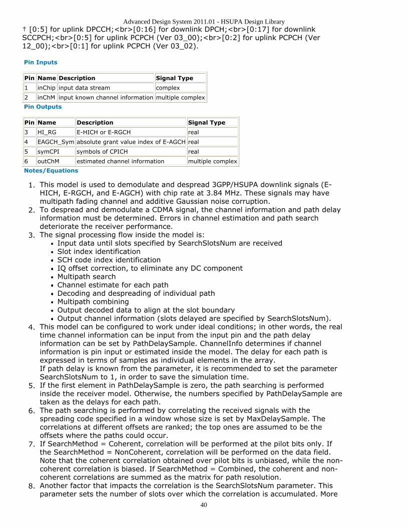
Pin Inputs
Pin Name Description Signal Type
1 inChip input data stream complex
2 inChM input known channel information multiple complex
Pin Outputs
Pin Name Description Signal Type
3 HI_RG E-HICH or E-RGCH real
4 EAGCH_Sym absolute grant value index of E-AGCH real
5 symCPI symbols of CPICH real
6 outChM estimated channel information multiple complex
Notes/Equations
This model is used to demodulate and despread 3GPP/HSUPA downlink signals (E-1.HICH, E-RGCH, and E-AGCH) with chip rate at 3.84 MHz. These signals may havemultipath fading channel and additive Gaussian noise corruption.To despread and demodulate a CDMA signal, the channel information and path delay2.information must be determined. Errors in channel estimation and path searchdeteriorate the receiver performance.The signal processing flow inside the model is:3.
Input data until slots specified by SearchSlotsNum are receivedSlot index identificationSCH code index identificationIQ offset correction, to eliminate any DC componentMultipath searchChannel estimate for each pathDecoding and despreading of individual pathMultipath combiningOutput decoded data to align at the slot boundaryOutput channel information (slots delayed are specified by SearchSlotsNum).
This model can be configured to work under ideal conditions; in other words, the real4.time channel information can be input from the input pin and the path delayinformation can be set by PathDelaySample. ChannelInfo determines if channelinformation is pin input or estimated inside the model. The delay for each path isexpressed in terms of samples as individual elements in the array.If path delay is known from the parameter, it is recommended to set the parameterSearchSlotsNum to 1, in order to save the simulation time.If the first element in PathDelaySample is zero, the path searching is performed5.inside the receiver model. Otherwise, the numbers specified by PathDelaySample aretaken as the delays for each path.The path searching is performed by correlating the received signals with the6.spreading code specified in a window whose size is set by MaxDelaySample. Thecorrelations at different offsets are ranked; the top ones are assumed to be theoffsets where the paths could occur.If SearchMethod = Coherent, correlation will be performed at the pilot bits only. If7.the SearchMethod = NonCoherent, correlation will be performed on the data field.Note that the coherent correlation obtained over pilot bits is unbiased, while the non-coherent correlation is biased. If SearchMethod = Combined, the coherent and non-coherent correlations are summed as the matrix for path resolution.Another factor that impacts the correlation is the SearchSlotsNum parameter. This8.parameter sets the number of slots over which the correlation is accumulated. More

Advanced Design System 2011.01 - HSUPA Design Library
41
slots are necessary for a reliable path resolution for signals with noise contamination.Usually, six slots are required if Eb/N0 is 2 dB. The user must determine theappropriate slot number and search method for the best trade-off between accuracyand speed.If the path delay is fixed, the path search is necessary only at the start of simulation.9.In this case, set PathSearch=Once to save simulation time. Otherwise, the pathsearch will be performed for each slot received to update the dynamic path delayinformation.Channel estimation varies according to channel type.10.
If ChannelType = CH_GAUSSIAN, the channel is assumed to be time-invariantand the IQ phase shift is estimated using the pilot field of the signals received sofar.If ChannelType = CH_FADING, channel characteristics are assumed to be time-variant and more complicated channel estimation must be used. A simplechannel estimation is used that takes the fading characteristic averaged over thepilot field of the current slot as the channel information for the entire slot.
Generally the pilot in current slots is enough for channel estimation. But if Eb/N0 is11.very low, while channel status varies relatively slowly, more slots are necessary for areliable channel estimation. EstSlotsNum can be used to set number of slots used forchannel estimation.Channel information that is estimated on CPICH or known from input pins is output12.from pin outChM for reference. Each firing, 2560 tokens are produced as the channelinformation for the chips of the current demodulation slot.
NoteIf ChannelInfo = Estimated, CPICH must be included in the received signal for the Rake receiver tomake the inside channel estimation.
All paths are combined assuming that all paths are useful for improving the decoding13.reliability. In some cases, paths with low SNR are actually harmful to the final SNRimprovement. The user must set PathNum for better decoding performance inmultipath conditions.This model can be used to decode E-AGCH and E-HICH / E-RGCH. These channels are14.assumed to be time-aligned. If decoding of a specific channel is not necessary, it canbe disabled by relative parameters to reduce simulation time.Each firing, the number of input tokens is 2560 × SampleRate. There is a delay in15.terms of slots associated with the decoded information. The results are output afterthe number of firings equals SearchSlotsNum.If the 3GPP/HSUPA signal is S(t), this signal may be delayed t1 by some filters (such16.as the Tx RC filters). So, the delayed signal is S(t-t1) and the signal from 0 to t1 iszero and the real 3GPP signal transmission starts from t1. When the delayed signalspass through a fading channel, the fading factor is applied to the overall signalsstarting from time 0. The offset t1 must be known if the receiver of the channelinformation is input from outside; this offset is expressed in terms of samples.
References
3GPP Technical Specification TS 25.211, "Physical channels and mapping of transport1.channels onto physical channels (FDD)," Version 7.10.0, Dec. 2008.3GPP Technical Specification TS 25.212, "Multiplexing and channel coding (FDD),"2.Version 7.9.0, Sept. 2008.3GPP Technical Specification TS 25.213, "Spreading and modulation (FDD)," Version3.7.6.0, Sept. 2008.

Advanced Design System 2011.01 - HSUPA Design Library
42
HSUPA_DL_Receiver
Description: HSUPA downlink receiverLibrary: HSUPA, Receivers
Parameters
Name Description Default Symbol Type Range
TTI Transmission timeinterval: TTI 2ms,TTI 10ms
TTI 2ms enum
EHICH_SqnIdx Signature sequenceindex of EHICH
0 int [0,39]
ERGCH_SqnIdx Signature sequenceindex of ERGCH
1 int [0,39]
EHI_ERG_SpreadCode Spreading code forE-HICH and E-RGCH
19 int [0,127]
EAGCH_SpreadCode Spreading code forE-AGCH
100 int [0,255]
ERNTI E-DCH radionetwork temporaryidentifier
19 int [0,65535]
ScrambleOffset Scramble codeoffset
0 int [0,15]
ScrambleType Scramble codetype: normal, right,left
normal enum
ScrambleCode Index of scramblecode
0 int [0,512] for downlink;<br>[0,16777215] for uplink
SamplesPerChip Samples per chip 8 S int [2,32]
MaxDelaySample Maximum delayboundary, in termsof samples
0 int [0,2559] for RAKEreceiver;<br>[0,102400] in othermodels
ChannelType Select the channeltype to beprocessed:CH_GAUSSIAN,CH_FADING
CH_GAUSSIAN enum
ChannelInfo Fading channelinformation source:Known, Estimated
Known enum
ChannelInfoOffset Offset betweenspread code andchannel informationin terms of sample
0 int [0,MaxDelaySample]
PathSearch Path searchfrequency:EverySlot, Once
Once enum
SearchMethod Path searchmethod: Coherent,NonCoherent,
Coherent enum

Advanced Design System 2011.01 - HSUPA Design Library
43
Combined
SearchSlotsNum Number of slots forpath search
1 int [1,12]
PathNum Number of Rakefingers
1 int [1,6]
PathDelaySample Delay for eachfinger, in terms ofsamples
0 intarray
[0,MaxDelaySample];<br>arraysize shall be equal to PathNum
RxEHICH_ERGCH Switch of EHICHand/or ERGCHdemodulation: OFF,ON
ON enum
RxEAGCH Switch of EAGCHdemodulation: OFF,ON
ON enum
Threshold_EHICH Threshold fordecoding E-HICH
-32 real (-∞,∞)
Threshold_ERGCH Threshold fordecoding E-RGCH
-20 real (-∞,∞)
Pin Inputs
Pin Name Description Signal Type
1 Input input complex
2 CH_M channel information multiple complex
Pin Outputs
Pin Name Description Signal Type
3 EHICH E-HICH real
4 ERGCH E-RGCH real
5 EAGCH E-AGCH int
Notes/Equations
This subnetwork model is used to demodulate and decode HSUPA related downlink1.signals, i.e., E-DCH Absolute Grant Channel (E-AGCH), E-DCH Hybrid ARQ IndicatorChannel (E-HICH), and E-DCH Relative Grant Channel (E-RGCH).The schematic for this subnetwork is shown below:2.
To despread and demodulate a CDMA signal, the channel information and path delay3.information must be determined. Errors in channel estimation and path searchdeteriorate the receiver performance.This model can be configured to work under ideal conditions; in other words, the real4.time channel information can be input from input pin and the path delay informationcan be set by PathDelaySample. ChannelInfo determines if channel information is pin

Advanced Design System 2011.01 - HSUPA Design Library
44
input or estimated inside the model. The delay for each path is expressed in terms ofsamples as individual elements in the array.If path delay is known from the parameter, it is recommended to set the parameterSearchSlotsNum to 1, in order to save the simulation time.If the first element in PathDelaySample is zero, the path searching is performed5.inside the receiver model. Otherwise, the numbers specified by PathDelaySample aretaken as the delays for each path.The path searching is performed by correlating the received signals with the6.spreading code specified in a window whose size is set by MaxDelaySample. Thecorrelations at different offsets are ranked; the top ones are assumed to be theoffsets where the paths could occur.If SearchMethod = Coherent, correlation will be performed at the pilot bits only. If7.the SearchMethod = NonCoherent, correlation will be performed on the data field.Note that the coherent correlation obtained over pilot bits is unbiased, while the non-coherent correlation is biased. If SearchMethod = Combined, the coherent and non-coherent correlations are summed as the matrix for path resolution.Another factor that impacts the correlation is the SearchSlotsNum parameter. This8.parameter sets the number of slots over which the correlation is accumulated. Moreslots are necessary for a reliable path resolution for signals with noise contamination.Usually, 6 slots are required if Eb/No is 2 dB. The user must determine theappropriate slot number and search method for the best trade-off between accuracyand speed.If the path delay is fixed, the path search is necessary only at the start of simulation.9.In this case, set PathSearch=Once to save simulation time. Otherwise, the pathsearch will be performed for each slot received to update the dynamic path delayinformation.Channel estimation varies according to channel type.10.
If ChannelType = CH_GAUSSIAN, the channel is assumed to be time-invariantand the IQ phase shift is estimated using the pilot field of the signals received sofar.If ChannelType = CH_FADING, channel characteristics are assumed to be time-variant and more complicated channel estimation must be used. A simplechannel estimation is used that takes the fading characteristic averaged over thepilot field of the current slot as the channel information for the entire slot.
Channel information that is estimated on CPICH or known from input pins.11.
NoteIf ChannelInfo = Estimated, CPICH must be included in the received signal for the Rake receiver tomake the inside channel estimation.
All paths are combined assuming that all paths are useful for improving the decoding12.reliability. In some cases, paths with low SNR are actually harmful to the final SNRimprovement. The user must set PathNum for better decoding performance inmultipath conditions.This model can be used to decode E-AGCH and E-HICH / E-RGCH. These channels are13.assumed to be time-aligned. If decoding of a specific channel is not necessary, it canbe disabled by relative parameters to reduce simulation time.There is a delay in terms of slots associated with the decoded information, and it14.varies for different SearchSlotsNum and TTI combinations.For more information regarding the Rake receiver and different channel decoders,15.please refer to the documents of HSUPA_DL_Rake, HSUPA_EAGCH_Decode, andHSUPA_EHICH_ERGCH_Decode respectively.
References
3GPP Technical Specification TS 25.211, "Physical channels and mapping of transport1.channels onto physical channels (FDD)," Version 7.10.0, Dec. 2005.3GPP Technical Specification TS 25.212, "Multiplexing and channel coding (FDD),"2.

Advanced Design System 2011.01 - HSUPA Design Library
45
Version 7.9.0, Sept. 2008.3GPP Technical Specification TS 25.213, "Spreading and modulation (FDD)," Version3.7.6.0, Sept. 2008.

Advanced Design System 2011.01 - HSUPA Design Library
46
HSUPA_DL_ReceiverRF
Description: HSUPA downlink receiverLibrary: HSUPA, Receivers
Parameters
Name Description Default Symbol Unit Type Range
RLoad Input resistance DefaultRLoad Ohm real (0,∞)
FCarrier Carrierfrequency
1950MHz Hz real (0,∞)
Phase Reference phasein degrees
0.0 deg real (-∞,∞)
SamplesPerChip Samples perchip
8 S int [2,32]
RRC_FilterLength RRC filter length(chips)
16 int [2,128]
ExcessBW Excessbandwidth ofraised cosinefilters
0.22 real (0.0,1.0)
ScrambleCode Index ofscramble code
0 int [0,512] for downlink;<br>[0,16777215] for uplink
ScrambleOffset Scramble codeoffset
0 int [0,15]
ScrambleType Scramble codetype: normal,right, left
normal enum
TTI Transmissiontime interval:TTI 2ms, TTI10ms
TTI 2ms enum
EHICH_SqnIdx Signaturesequence indexof EHICH
0 int [0,39]
ERGCH_SqnIdx Signaturesequence indexof ERGCH
1 int [0,39]
EHI_ERG_SpreadCode Spreading codefor E-HICH andE-RGCH
19 int [0,127]
EAGCH_SpreadCode Spreading codefor E-AGCH
100 int [0,255]
ERNTI E-DCH radionetworktemporaryidentifier
19 int [0,65535]
MaxDelaySample Maximum delayboundary, interms ofsamples
0 int [0,2559] for RAKEreceiver;<br>[0,102400] inother models

Advanced Design System 2011.01 - HSUPA Design Library
47
ChannelType Select thechannel type tobe processed:CH_GAUSSIAN,CH_FADING
CH_GAUSSIAN enum
ChannelInfo Fading channelinformationsource: Known,Estimated
Known enum
ChannelInfoOffset Offset betweenspread code andchannelinformation interms of sample
0 int [0,MaxDelaySample]
PathSearch Path searchfrequency:EverySlot, Once
Once enum
SearchMethod Path searchmethod:Coherent,NonCoherent,Combined
Coherent enum
SearchSlotsNum Number of slotsfor path search
1 int [1,12]
PathNum Number of Rakefingers
1 int [1,6]
PathDelaySample Delay for eachfinger, in termsof samples
0 intarray
[0,MaxDelaySample];<br>arraysize shall be equal to PathNum
RxEHICH_ERGCH Switch of EHICHand/or ERGCHdemodulation:OFF, ON
ON enum
RxEAGCH Switch ofEAGCHdemodulation:OFF, ON
ON enum
Threshold_EHICH Threshold fordecoding E-HICH
-32 real (-∞,∞)
Threshold_ERGCH Threshold fordecoding E-RGCH
-20 real (-∞,∞)
Pin Inputs
Pin Name Description Signal Type
1 RF input timed
2 CH_M channel information multiple complex
Pin Outputs
Pin Name Description Signal Type
3 EHICH E-HICH real
4 ERGCH E-RGCH real
5 EAGCH E-AGCH int
Notes/Equations
This subnetwork model is used to demodulate and decode HSUPA related downlink RF1.signals, i.e., E-DCH Absolute Grant Channel (E-AGCH), E-DCH Hybrid ARQ IndicatorChannel (E-HICH), and E-DCH Relative Grant Channel (E-RGCH).

Advanced Design System 2011.01 - HSUPA Design Library
48
The schematic for this subnetwork is shown below:2.
To despread and demodulate a CDMA signal, the channel information and path delay3.information must be determined. Errors in channel estimation and path searchdeteriorate the receiver performance.This model can be configured to work under ideal conditions; in other words, the real4.time channel information can be input from input pin and the path delay informationcan be set by PathDelaySample. ChannelInfo determines if channel information is pininput or estimated inside the model. The delay for each path is expressed in terms ofsamples as individual elements in the array.If path delay is known from the parameter, it is recommended to set the parameterSearchSlotsNum to 1, in order to save the simulation time.If the first element in PathDelaySample is zero, the path searching is performed5.inside the receiver model. Otherwise, the numbers specified by PathDelaySample aretaken as the delays for each path.The path searching is performed by correlating the received signals with the6.spreading code specified in a window whose size is set by MaxDelaySample. Thecorrelations at different offsets are ranked; the top ones are assumed to be theoffsets where the paths could occur.If SearchMethod = Coherent, correlation will be performed at the pilot bits only. If7.the SearchMethod = NonCoherent, correlation will be performed on the data field.Note that the coherent correlation obtained over pilot bits is unbiased, while the non-coherent correlation is biased. If SearchMethod = Combined, the coherent and non-coherent correlations are summed as the matrix for path resolution.Another factor that impacts the correlation is the SearchSlotsNum parameter. This8.parameter sets the number of slots over which the correlation is accumulated. Moreslots are necessary for a reliable path resolution for signals with noise contamination.Usually, six slots are required if Eb/N0 is 2 dB. The user must determine theappropriate slot number and search method for the best trade-off between accuracyand speed.If the path delay is fixed, the path search is necessary only at the start of simulation.9.In this case, set PathSearch=Once to save simulation time. Otherwise, the pathsearch will be performed for each slot received to update the dynamic path delayinformation.Channel estimation varies according to channel type.10.
If ChannelType = CH_GAUSSIAN, the channel is assumed to be time-invariantand the IQ phase shift is estimated using the pilot field of the signals received sofar.If ChannelType = CH_FADING, channel characteristics are assumed to be time-variant and more complicated channel estimation must be used. A simplechannel estimation is used that takes the fading characteristic averaged over thepilot field of the current slot as the channel information for the entire slot.
Channel information that is estimated on CPICH or known from input pins.11.
NoteIf ChannelInfo = Estimated, CPICH must be included in the received signal for the Rake receiver tomake the inside channel estimation.
All paths are combined assuming that all paths are useful for improving the decoding12.

Advanced Design System 2011.01 - HSUPA Design Library
49
reliability. In some cases, paths with low SNR are actually harmful to the final SNRimprovement. The user must set PathNum for better decoding performance inmultipath conditions.This model can be used to decode E-AGCH and E-HICH / E-RGCH. These channels are13.assumed to be time-aligned. If decoding of a specific channel is not necessary, it canbe disabled by relative parameters to reduce simulation time.There is a delay in terms of slots associated with the decoded information, and it14.varies for different SearchSlotsNum and TTI combinations.For more information regarding the Rake receiver and different channel decoders,15.please see HSUPA_DL_Rake (hsupa), HSUPA_EAGCH_Decode (hsupa), andHSUPA_EHICH_ERGCH_Decode (hsupa).
References
3GPP Technical Specification TS 25.211, "Physical channels and mapping of transport1.channels onto physical channels (FDD)," Version 6.7.0, Dec. 2005.3GPP Technical Specification TS 25.212, "Multiplexing and channel coding (FDD),"2.Version 6.7.0, Dec. 2005.3GPP Technical Specification TS 25.213, "Spreading and modulation (FDD)," Version3.6.5.0, Mar. 2006.3GPP Technical Specification TS 25.214, "Physical layer procedures (FDD)," Version4.6.8.0, Mar. 2006.3GPP Technical Specification TS 25.101, "UE Radio transmission and Reception5.(FDD)," Version 6.11.0, Mar. 2006.

Advanced Design System 2011.01 - HSUPA Design Library
50
HSUPA_DL_Source
Description: HSUPA downlink sourceLibrary: HSUPA, Signal Sources
Parameters
Name Description Default Type Range
TTI Transmission timeinterval: TTI 2ms, TTI10ms
TTI 2ms enum
EHICH_SgnlPttrn E-HICH signal pattern 1.0 intarray
[-1, +1]
ERGCH_SgnlPttrn E-RGCH signalpattern
1.0 intarray
[-1, +1]
EHICH_SqnIdx Signature sequenceindex of EHICH
0 int [0,39]
ERGCH_SqnIdx Signature sequenceindex of ERGCH
1 int [0,39]
EHI_ERG_SpreadCode Spreading code for E-HICH and E-RGCH
19 int [0,127]
EAGCH_SpreadCode Spreading code for E-AGCH
100 int [0,255]
ERNTI E-DCH radio networktemporary identifier
19 int [0,65535]
EHICH_GainFactor EHICH power gain indB
1.0 real (-∞,∞)
ERGCH_GainFactor ERGCH power gain indB
1.0 real (-∞,∞)
EAGCH_GainFactor EAGCH power gain indB
1.0 real (-∞,∞)
ScrambleOffset Scramble code offset 0 int [0,15]
ScrambleType Scramble code type:normal, right, left
normal enum
ScrambleCode Index of scramblecode
0 int [0,512] for downlink;<br>[0,16777215] for uplink
RefCh Referencemeasurementchannel:
DL_REF_12_2 enum

Advanced Design System 2011.01 - HSUPA Design Library
51
DL_REF_12_2,DL_REF_64,DL_REF_144,DL_REF_384
DPCH_SpreadCode Spread code index ofDPCH
127 int [0,127] for 12.2kbps;<br>[0,31]for 64kbps;<br>[0,15] for144kbps;<br>[0,7] for 384kbps
CPICH_SpreadCode Spread code index ofCPICH
2 int [0,255]
PICH_SpreadCode Spread code index ofPICH
16 int [0,255]
SCCPCH_SlotFormat SCCPCH slot format 0 int [0,17]
SCCPCH_SpreadCode Spread code index ofSCCPCH
3 int [0,SpreadFactor-1];<br>SpreadFactor is set bySCCPCH_SlotFormat
DPCH_GainFactor DPCH Ec over Ior indB, valid only ifPowerReference is Ior
1.0 real (-∞,∞)
P_CPICH_GainFactor Primary CPICH powergain in dB
1.0 real (-∞,∞)
S_CPICH_GainFactor Secondary CPICHpower gain in dB
1.0 real (-∞,∞)
PCCPCH_GainFactor PCCPCH power gain indB
1.0 real (-∞,∞)
SCCPCH_GainFactor SCCPCH power gainin dB
1.0 real (-∞,∞)
P_SCH_GainFactor Primary SCH powergain in dB
1.0 real (-∞,∞)
S_SCH_GainFactor Secondary SCH powergain in dB
1.0 real (-∞,∞)
PICH_GainFactor PICH power gain indB
1.0 real (-∞,∞)
OCNS_GainFactor OCNS gain in dB,valid only ifPowerReference isDPCH_Ec
1.0 real (-∞,∞)
OCNS_ChannelNum OCNS channelnumber
16 int [1,512]
OCNS_PowerArray OCNS channel powerarray in dB
-1 -3 -3 -5 -2 -4-8 -7 -4 -6 -5 -9-10 -8 -6 0
realarray
(-∞,∞);<br>the array size shallbe equal to OCNS_ChannelNum
OCNS_SpreadFactorArray OCNS spread factorarray
128 128 128128 128 128128 128 128128 128 128128 128 128128
intarray
2 n, n=1,...,9;<br>array sizeshall be equal toOCNS_ChannelNum
OCNS_SpreadCodeArray OCNS spread codearray
2 11 17 23 3138 47 55 62 6978 85 94 125113 119
intarray
[0,OCNS_SpreadFactorArray-1];<br>array size shall be equalto OCNS_ChannelNum;<br>codeconflict is checked
OCNS_DataPatternArray OCNS data patternarray: 0-random, 1-PN9, 2-PN15, 3-Repeat Bits
0 0 0 0 0 0 0 00 0 0 0 0 0 0 0
intarray
[0,1,2,3];<br>array size shall beequal to OCNS_ChannelNum
OCNS_RepBitValueArray OCNS repeat bit valuearray
0 0 0 0 0 0 0 00 0 0 0 0 0 0 0
intarray
[0,255];<br>array size shall beequal to OCNS_ChannelNum
OCNS_tOffsetArray OCNS time offset interms of 256 chips
0 0 0 0 0 0 0 00 0 0 0 0 0 0 0
intarray
[0,149];<br>array size shall beequal to OCNS_ChannelNum

Advanced Design System 2011.01 - HSUPA Design Library
52
DTCHDataPattern DTCH source datapattern:DTCH_random,DTCH_PN9,DTCH_PN15,DTCH_bits_repeat,DTCH_user_file
DTCH_random enum
DTCHRepBitValue DTCH repeating datavalue
0xff int [0,255]
DTCHUserFileName DTCH user-defineddata file name
datafile.txt filename
DCCHDataPattern DCCH source datapattern:DCCH_random,DCCH_PN9,DCCH_PN15,DCCH_bits_repeat,DCCH_user_file
DCCH_random enum
DCCHRepBitValue DCCH repeating datavalue
0xff int [0,255]
DCCHUserFileName DCCH user-defineddata file name
datafile.txt filename
TPCDataPattern Source data pattern:TPC_random,TPC_PN9, TPC_PN15,TPC_bits_repeat,TPC_user_file
TPC_random enum
TPCRepBitValue TPC repeating datavalue
0xff int [0,255]
TPCUserFileName TPC user-defined datafile name
datafile.txt filename
Pin Outputs
Pin Name Description Signal Type
1 Output output complex
2 STTD space time transmit diversityoutput
complex
3 DTCH DTCH data int
4 DCCH DCCH data int
5 EHICH E-HICH data real
6 ERGCH E-RGCH data real
7 EAGCH E-AGCH int
Notes/Equations
This subnetwork model is used to simulate integrated base station signal source.1.The schematic for this subnetwork is shown below:2.

Advanced Design System 2011.01 - HSUPA Design Library
53
The physical channels integrated in this subnetwork model are listed in the following3.table:Physical Channel
P_CPICH
S_CPICH
PCCPCH
P_SCH
S_SCH
SCCPCH
PICH
DPCH
E-AGCH
E-HICH
E-RGCH
OCNS
The DPCH is generated by the fully-coded 3GPPFDD_DL_RefCh signal source.4.DTCH, DCCH, and TPC patterns can be set through the DTCHDataPattern,5.DCCHDataPattern, and TPCDataPattern parameters; Five data patterns aresupported: random, PN9, PN15, fixed repeated 8-bits, and user-defined file.If the data pattern is 8-bits repeating, the bits to be repeated are set by the6.respective RepBitValue. For example if RepBitValue is set as 0x7a, bit sequence0,1,1,1,1,0,1,0 will be output repeatedly.If data is from a user-defined file, the file name is defined by the respective7.UserFileName. The user can edit the file with any text editor. The separator betweenbits can be a space, comma, or any other separator. If the bit sequence is shorterthan the output length, data will be output repeatedly.The DPCH data rate can be set through RefCh. DPCH channelization code is set8.through DPCH_SpreadCode.CPICH includes primary and secondary CPICH. Primary CPICH channelization code is9.fixed at C256,0. CPICH_SpreadCode is set on secondary CPICH, with a spread factorof 256.The PICH spread factor is 256. PICH channelization code is set through10.PICH_SpreadCode.The PCCPCH channelization code is fixed at C256,1. The SCCPCH spread factor and11.spread channelization code are set through SCCPCH_SpreadFactor and

Advanced Design System 2011.01 - HSUPA Design Library
54
SCCPCH_SpreadCode.The E-HICH can be set by EHICH_SgnlPttrn (Signal Pattern), EHICH_SqnIdx12.(Signature Sequence Index), and EHI_ERG_SpreadCode.The E-RGCH can be set by ERGCH_SgnlPttrn (Signal Pattern), ERGCH_SqnIdx13.(Signature Sequence Index), and EHI_ERG_SpreadCode.The E-AGCH can be set by EAGCH_SpreadCode and ERNTI.14.Relative gain factor of each channel can be set through the respective GainFactor15.parameters. They are multiplied to the output of each channel model. A channel canbe disabled by setting its gain factor to 0.It is suggested that the square of all the GainFactors add up to 1 to make sure the16.RMS value of output downlink signal is 1. However, it isn't so important for thebaseband signal. A normalized downlink source can be implemented byHSUPA_DL_SourceRF.OCNS can be set through the OCNS_ChannelNum and six OCNS array parameters.17.The default OCNS channel is 16 and corresponding array parameters are 16 elementslong. To change the OCNS channel number, the corresponding array parametersmust be changed. For details regarding OCNS settings, see HSUPA_OCNS (hsupa).
References
3GPP Technical Specification TS 25.211, "Physical channels and mapping of transport1.channels onto physical channels (FDD)," Version 6.7.0, Dec. 2005.3GPP Technical Specification TS 25.212, "Multiplexing and channel coding (FDD),"2.Version 6.7.0, Dec. 2005.3GPP Technical Specification TS 25.213, "Spreading and modulation (FDD)," Version3.6.5.0, Mar. 2006.

Advanced Design System 2011.01 - HSUPA Design Library
55
HSUPA_DL_SourceRF
Description: HSUPA RF downlink signal sourceLibrary: HSUPA, Signal Sources
Parameters
Name Description Default Symbol Unit Type Range
ROut Source resistance DefaultROut Ohm real (0,∞)
RTemp Temperature DefaultRTemp Celsius real [-273.15,∞)
TStep Expressionshowing howTStep is related tothe other sourceparameters
1/3.84MHz/SamplesPerChip
string
FCarrier Carrier frequency 1950MHz Hz real (0,∞)
Power Power, valid only ifPowerReferencesetting is Ior
dbmtow(43.0) W real [0,∞)
PowerReference Reference for allchannels withrelative powerlevel: Ior,DPCH__Ec
Ior enum
DPCH_Ec Ec of DPCH indBm/3.84 MHz
-100 dB real (-∞,∞)
MirrorSpectrum Mirror spectrumabout carrier?:NO, YES
NO enum
GainImbalance Gain imbalance, Qvs I
0.0 dB real (-∞,∞)
PhaseImbalance Phase imbalance,Q vs I
0.0 deg real (-∞,∞)
I_OriginOffset I origin offset(percent)
0.0 real (-∞,∞)
Q_OriginOffset Q origin offset(percent)
0.0 real (-∞,∞)
IQ_Rotation IQ rotation 0.0 deg real (-∞,∞)
SamplesPerChip Samples per chip 8 S int [2,32]

Advanced Design System 2011.01 - HSUPA Design Library
56
RRC_FilterLength RRC filter length(chips)
16 int [2,128]
ExcessBW Excess bandwidthof raised cosinefilters
0.22 real (0.0,1.0)
ScrambleCode Index of scramblecode
0 int [0,512] for downlink;<br>[0,16777215] for uplink
ScrambleOffset Scramble codeoffset
0 int [0,15]
ScrambleType Scramble codetype: normal,right, left
normal enum
TTI Transmission timeinterval: TTI 2ms,TTI 10ms
TTI 2ms enum
EHICH_SgnlPttrn E-HICH signalpattern
1.0 intarray
[-1, +1]
ERGCH_SgnlPttrn E-RGCH signalpattern
1.0 intarray
[-1, +1]
EHICH_SqnIdx Signaturesequence index ofEHICH
0 int [0,39]
ERGCH_SqnIdx Signaturesequence index ofERGCH
1 int [0,39]
EHI_ERG_SpreadCode Spreading code forE-HICH and E-RGCH
19 int [0,127]
EAGCH_SpreadCode Spreading code forE-AGCH
100 int [0,255]
ERNTI E-DCH radionetwork temporaryidentifier
19 int [0,65535]
EHICH_GainFactor EHICH power gainin dB
-28.3 dB real (-∞,∞)
ERGCH_GainFactor ERGCH power gainin dB
-24.4 dB real (-∞,∞)
EAGCH_GainFactor EAGCH power gainin dB
-23.2 dB real (-∞,∞)
RefCh Referencemeasurementchannel:DL_REF_12_2,DL_REF_64,DL_REF_144,DL_REF_384
DL_REF_12_2 enum
DPCH_SpreadCode Spread code indexof DPCH
127 int [0,127] for12.2kbps;<br>[0,31] for64kbps;<br>[0,15] for144kbps;<br>[0,7] for384kbps
CPICH_SpreadCode Spread code indexof CPICH
2 int [0,255]
PICH_SpreadCode Spread code indexof PICH
16 int [0,255]
SCCPCH_SlotFormat SCCPCH slotformat
0 int [0,17]
SCCPCH_SpreadCode Spread code indexof SCCPCH
3 int [0,SpreadFactor-1];<br>SpreadFactor is set by

Advanced Design System 2011.01 - HSUPA Design Library
57
SCCPCH_SlotFormat
DPCH_GainFactor DPCH Ec over Iorin dB, valid only ifPowerReference isIor
-15 dB real (-∞,∞)
P_CPICH_GainFactor Primary CPICHpower gain in dB
-10.0 dB real (-∞,∞)
S_CPICH_GainFactor Secondary CPICHpower gain in dB
-300.0 dB real (-∞,∞)
PCCPCH_GainFactor PCCPCH powergain in dB
-12 dB real (-∞,∞)
SCCPCH_GainFactor SCCPCH powergain in dB
-300 dB real (-∞,∞)
P_SCH_GainFactor Primary SCHpower gain in dB
-15 dB real (-∞,∞)
S_SCH_GainFactor Secondary SCHpower gain in dB
-15 dB real (-∞,∞)
PICH_GainFactor PICH power gain indB
-15 dB real (-∞,∞)
OCNS_GainFactor OCNS gain in dB,valid only ifPowerReference isDPCH_Ec
-300 dB real (-∞,∞)
OCNS_ChannelNum OCNS channelnumber
16 int [1,512]
OCNS_PowerArray OCNS channelpower array in dB
-1 -3 -3 -5 -2 -4 -8 -7 -4 -6 -5 -9 -10 -8 -6 0
realarray
(-∞,∞);<br>the array sizeshall be equal toOCNS_ChannelNum
OCNS_SpreadFactorArray OCNS spreadfactor array
128 128 128 128128 128 128 128128 128 128 128128 128 128 128
intarray
2 n, n=1,...,9;<br>array sizeshall be equal toOCNS_ChannelNum
OCNS_SpreadCodeArray OCNS spread codearray
2 11 17 23 31 38 4755 62 69 78 85 94125 113 119
intarray
[0,OCNS_SpreadFactorArray-1];<br>array size shall beequal toOCNS_ChannelNum;<br>codeconflict is checked
OCNS_DataPatternArray OCNS data patternarray: 0-random,1-PN9, 2-PN15, 3-Repeat Bits
0 0 0 0 0 0 0 0 0 0 00 0 0 0 0
intarray
[0,1,2,3];<br>array size shallbe equal toOCNS_ChannelNum
OCNS_RepBitValueArray OCNS repeat bitvalue array
0 0 0 0 0 0 0 0 0 0 00 0 0 0 0
intarray
[0,255];<br>array size shallbe equal toOCNS_ChannelNum
OCNS_tOffsetArray OCNS time offsetin terms of 256chips
0 0 0 0 0 0 0 0 0 0 00 0 0 0 0
intarray
[0,149];<br>array size shallbe equal toOCNS_ChannelNum
DTCHDataPattern DTCH source datapattern:DTCH_random,DTCH_PN9,DTCH_PN15,DTCH_bits_repeat,DTCH_user_file
DTCH_random enum
DTCHRepBitValue DTCH repeatingdata value
0xff int [0,255]
DTCHUserFileName DTCH user-defineddata file name
datafile.txt filename
DCCHDataPattern DCCH source datapattern:
DCCH_random enum

Advanced Design System 2011.01 - HSUPA Design Library
58
DCCH_random,DCCH_PN9,DCCH_PN15,DCCH_bits_repeat,DCCH_user_file
DCCHRepBitValue DCCH repeatingdata value
0xff int [0,255]
DCCHUserFileName DCCH user-defineddata file name
datafile.txt filename
TPCDataPattern Source datapattern:TPC_random,TPC_PN9,TPC_PN15,TPC_bits_repeat,TPC_user_file
TPC_random enum
TPCRepBitValue TPC repeating datavalue
0xff int [0,255]
TPCUserFileName TPC user-defineddata file name
datafile.txt filename
Pin Outputs
Pin Name Description Signal Type
1 RF RF output timed
2 EVM_Ref reference signal for EVM complex
3 DTCH DTCH data int
4 DCCH DCCH data int
5 EHICH E-HICH data real
6 ERGCH E-RGCH data real
7 EAGCH E-AGCH int
Notes/Equations
This subnetwork model is used to simulate integrated base station RF signal source.1.The schematic for this subnetwork is shown below:2.

Advanced Design System 2011.01 - HSUPA Design Library
59
The physical channels integrated in this subnetwork model are listed below:3.Physical Channel
P_CPICH
S_CPICH
PCCPCH
P_SCH
S_SCH
SCCPCH
PICH
DPCH
E-AGCH
E-HICH
E-RGCH
OCNS
The DPCH is generated by the fully-coded 3GPPFDD_DL_RefCh signal source.4.DTCH, DCCH, and TPC patterns can be set through the DTCHDataPattern,5.DCCHDataPattern, and TPCDataPattern parameters; five data patterns aresupported: random, PN9, PN15, fixed repeated 8-bits, and user-defined file.If the data pattern is 8-bits repeating, the bits to be repeated are set by the6.respective RepBitValue. For example if RepBitValue is set as 0x7a, bit sequence0,1,1,1,1,0,1,0 will be output repeatedly.If data is from a user-defined file, the file name is defined by the respective7.UserFileName. The user can edit the file with any text editor. The separator betweenbits can be a space, comma, or any other separator. If the bit sequence is shorterthan the output length, data will be output repeatedly.The DPCH data rate can be set through RefCh. DPCH channelization code is set8.through DPCH_SpreadCode.CPICH includes primary and secondary CPICH. Primary CPICH channelization code is9.fixed at C256,0. CPICH_SpreadCode is set on secondary CPICH, with a spread factor

Advanced Design System 2011.01 - HSUPA Design Library
60
of 256.The PICH spread factor is 256. PICH channelization code is set through10.PICH_SpreadCode.The PCCPCH channelization code is fixed at C256,1. The SCCPCH spread factor and11.spread channelization code are set through SCCPCH_SpreadFactor andSCCPCH_SpreadCode.The E-HICH can be set by EHICH_SgnlPttrn (Signal Pattern), EHICH_SqnIdx12.(Signature Sequence Index), and EHI_ERG_SpreadCode.The E-RGCH can be set by ERGCH_SgnlPttrn (Signal Pattern), ERGCH_SqnIdx13.(Signature Sequence Index), and EHI_ERG_SpreadCode.The E-AGCH can be set by EAGCH_SpreadCode and ERNTI.14.There are two ways to set the power ratio defined in Table C.2 and Table C.3 in [5].15.Although each of these two ways can be converted to the other by calculation, theparameter PowerReference is provided for the user to set the power easily.If PowerReference is Ior, the power of transmitter is set by parameter Power; if it is16.DPCH_Ec, the power of transmitter depends on the value of parameter DPCH_Ec andis calculated in the equations of the subnetwork.Relative power levels of each channel can then be set through the respective17.GainFactor parameters, in dB units.
If PowerReference is Ior, OCNS_GainFactor is calculated from other GainFactors.(Refer to Table C.6 in [5]);If PowerReference is DPCH_Ec, the relative Ior is calculated. DPCH_GainFactor isequal to the inverse of Ior.All "GainFactors" are changed to power ratio over Ior by multiplyingDPCH_GainFactor.The GainFactors are converted into voltage values and multiplied to the outputof each channel model. A channel can be disabled by setting its gain factor to alarge minus value such as -300 dB.
OCNS can be set through the OCNS_ChannelNum and six OCNS array parameters.18.The default OCNS channel is 16 and corresponding array parameters are 16 elementslong. To change the OCNS channel number, the corresponding array parametersmust be changed. The output of OCNS must be normalized. For details regardingOCNS settings, see HSUPA_OCNS (hsupa).
References
3GPP Technical Specification TS 25.211, "Physical channels and mapping of transport1.channels onto physical channels (FDD)," Version 6.7.0, Dec. 2005.3GPP Technical Specification TS 25.212, "Multiplexing and channel coding (FDD),"2.Version 6.7.0, Dec. 2005.3GPP Technical Specification TS 25.213, "Spreading and modulation (FDD)," Version3.6.5.0, Mar. 2006.3GPP Technical Specification TS 25.214, "Physical layer procedures (FDD)," Version4.6.8.0, Mar. 2006.3GPP Technical Specification TS 25.101, "UE Radio transmission and Reception5.(FDD)," Version 6.11.0, Mar. 2006.

Advanced Design System 2011.01 - HSUPA Design Library
61
HSUPA_EAGCH
Description: E-DCH absolute grant channelLibrary: HSUPA, Signal Sources
Parameters
Name Description Default Type Range
TTI Transmission time interval: TTI2ms, TTI 10ms
TTI 2ms enum
EAGCH_SpreadCode Spreading code for E-AGCH 100 int [0,255]
ERNTI E-DCH radio network temporaryidentifier
19 int [0,65535]
ScrambleOffset Scramble code offset 0 int [0,15]
ScrambleType Scramble code type: normal,right, left
normal enum
ScrambleCode Index of scramble code 0 int [0,512] for downlink;<br>[0,16777215] for uplink
Pin Inputs
Pin Name Description Signal Type
1 ValueIdx absolute grant valueindex
int
2 Scope absolute grant scope int
Pin Outputs
Pin Name Description Signal Type
3 Output output complex
4 STTD space time transmit diversityoutput
complex
5 EAGCH E-AGCH int
Notes/Equations
This subnetwork model is used to generate the 3GPP/HSUPA absolute grant channel1.(E-AGCH) as defined in [2], Figure 24: "Coding for E-AGCH".The schematic for this subnetwork is shown below:2.

Advanced Design System 2011.01 - HSUPA Design Library
62
This subnetwork model completes the following operations:3.Multiplexing of E-AGCH information: Absolute Grant Value and Absolute GrantScopeCRC attachment for E-AGCH (including E-RNTI mask)Channel coding for E-AGCHRate matching for E-AGCHPhysical channel mapping for E-AGCH.
References
3GPP Technical Specification TS 25.211, "Physical channels and mapping of transport1.channels onto physical channels (FDD)," Version 6.7.0, Dec. 2005.3GPP Technical Specification TS 25.212, "Multiplexing and channel coding (FDD),"2.Version 6.7.0, Dec. 2005.3GPP Technical Specification TS 25.213, "Spreading and modulation (FDD)," Version3.6.5.0, Mar. 2006.

Advanced Design System 2011.01 - HSUPA Design Library
63
HSUPA_EAGCH_Decode
Description: Channel decoder of E-DCH absolute grant channelLibrary: HSUPA, Demultiplexers & Decoders
Parameters
Name Description Default Type Range
TTI Transmission time interval: TTI 2ms, TTI 10ms TTI 2ms enum
ERNTI E-DCH radio network temporary identifier 19 int [0,65535]
Pin Inputs
Pin Name Description Signal Type
1 AG_Sym input symbols real
Pin Outputs
Pin Name Description Signal Type
2 EAGCH Information bits for H-AGCH
int
3 Parity The result of CRC int
4 ValueIdx absolute grant value index int
5 Scope absolute grant scope int
Notes/Equations
This subnetwork model completes the inverse process of "Coding for E-AGCH", which1.is defined in [2], Figure 24.The schematic for this subnetwork is shown below:2.
This subnetwork model completes the following operations:3.Rate de-matching for E-AGCHViterbi decoding for E-AGCHCRC checking for E-AGCHDe-multiplexing of E-AGCH information: Absolute Grant Value and AbsoluteGrant Scope

Advanced Design System 2011.01 - HSUPA Design Library
64
References
3GPP Technical Specification TS 25.211, "Physical channels and mapping of transport1.channels onto physical channels (FDD)," Version 7.10.0, Dec. 2008.3GPP Technical Specification TS 25.212, "Multiplexing and channel coding (FDD),"2.Version 7.9.0, Sept. 2005.3GPP Technical Specification TS 25.213, "Spreading and modulation (FDD)," Version3.7.6.0, Sept. 2006.

Advanced Design System 2011.01 - HSUPA Design Library
65
HSUPA_EAGCH_DeRM
Description: HSUPA E-AGCH rate dematcherLibrary: HSUPA, Demultiplexers & Decoders
Pin Inputs
Pin Name Description Signal Type
1 Input input real
Pin Outputs
Pin Name Description Signal Type
2 Output output real
Notes/Equations
This model completes the inverse process of "Rate matching for E-AGCH", which is1.defined in [2].Each firing, 60 tokens are consumed; 90 tokens are output. The output tokens are2.obtained by inserting 30 zeros "z 1, z 2, z 5, z 6, z 7, z 11, z 12, z 14, z 15, z 17, z 23, z
24, z 31, z 37, z 44, z 47, z 61, z 63, z 64, z 71, z 72, z 75, z 77, z 80, z 83, z 84, z 85, z 87
, z 88, z 90" to the input tokens.
NoteThe position numbers (1, 2, 5, ..., 87, 88, 90) above are positions relative to the output tokens.
References
3GPP Technical Specification TS 25.211, "Physical channels and mapping of transport1.channels onto physical channels (FDD)," Version 6.7.0, Dec. 2005.3GPP Technical Specification TS 25.212, "Multiplexing and channel coding (FDD),"2.Version 6.7.0, Dec. 2005.3GPP Technical Specification TS 25.213, "Spreading and modulation (FDD)," Version3.6.5.0, Mar. 2006.
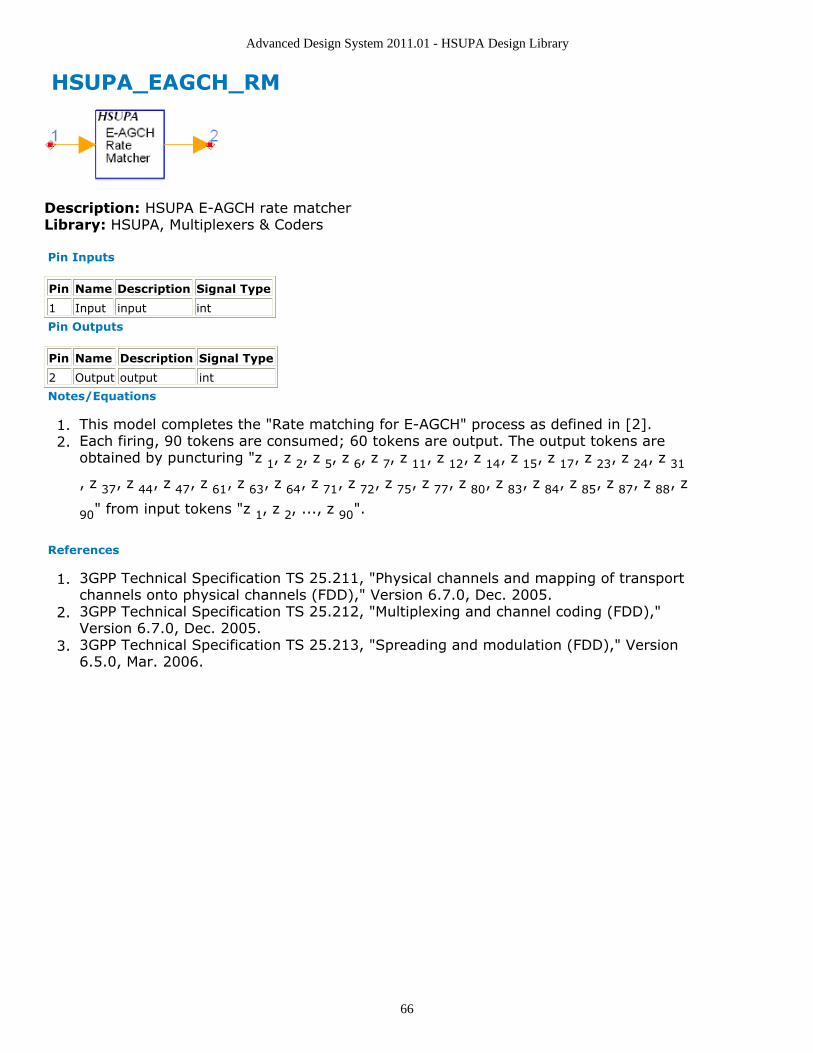
Advanced Design System 2011.01 - HSUPA Design Library
66
HSUPA_EAGCH_RM
Description: HSUPA E-AGCH rate matcherLibrary: HSUPA, Multiplexers & Coders
Pin Inputs
Pin Name Description Signal Type
1 Input input int
Pin Outputs
Pin Name Description Signal Type
2 Output output int
Notes/Equations
This model completes the "Rate matching for E-AGCH" process as defined in [2].1.Each firing, 90 tokens are consumed; 60 tokens are output. The output tokens are2.obtained by puncturing "z 1, z 2, z 5, z 6, z 7, z 11, z 12, z 14, z 15, z 17, z 23, z 24, z 31
, z 37, z 44, z 47, z 61, z 63, z 64, z 71, z 72, z 75, z 77, z 80, z 83, z 84, z 85, z 87, z 88, z
90" from input tokens "z 1, z 2, ..., z 90".
References
3GPP Technical Specification TS 25.211, "Physical channels and mapping of transport1.channels onto physical channels (FDD)," Version 6.7.0, Dec. 2005.3GPP Technical Specification TS 25.212, "Multiplexing and channel coding (FDD),"2.Version 6.7.0, Dec. 2005.3GPP Technical Specification TS 25.213, "Spreading and modulation (FDD)," Version3.6.5.0, Mar. 2006.

Advanced Design System 2011.01 - HSUPA Design Library
67
HSUPA_EDPCCH_ChDecode
Description: HSUPA E-DPCCH channel decoderLibrary: HSUPA, Demultiplexers & Decoders
Parameters
Name Description Default Type Range
TTI Transmission time interval: TTI 2ms, TTI 10ms TTI 2ms enum
Threshold Threshold -23.6 real (-∞,∞)
Pin Inputs
Pin Name Description Signal Type
1 Input input real
2 PwrN power of noise estimated from DPCCH real
Pin Outputs
Pin Name Description Signal Type
3 Output output int
4 ActiveE E-DPCCH flag, 1 for good frames, 0 for badframes
int
Notes/Equations
This model is used to implement channel decoding for HSUPA uplink E-DPCCH.1.Each firing, 10 Output token and one ActiveE token are produced when 30 Input and2.DPCCH tokens consumedPower of input E-DPCCH signal is estimated. SNR over noise power estimated from3.DPCCH is calculated and compared with a threshold. If SNR is less than thethreshold, no enhanced uplink channel is detected and the output of ActiveE is 0,otherwise it is detected and the output of ActiveE is 1.In any case, the input signal will be decoded and output in the pin Output as if4.enhanced uplink channel did send in the transmit end.The performance of E-DPCCH false alarm test and missed detection test is strongly5.correlated to each other, and is determined by the threshold of power detection. Thisthreshold is very sensitive to the change of power of configuration of uplink channels.The E-DPCCH performance test follows this order:
Sweeping Threshold to get target "false alarm"(1% in [4]).Set the Threshold and run simulation of missed detection.Compare the result of simulation with target "missed detction"(0.2% in [4]).
References
3GPP Technical Specification TS 25.211, "Physical channels and mapping of transport1.channels onto physical channels (FDD)," Version 7.10.0, Dec. 2008.3GPP Technical Specification TS 25.212, "Multiplexing and channel coding (FDD),"2.Version 7.9.0, Sept. 2008.3GPP Technical Specification TS 25.213, "Spreading and modulation (FDD)," Version3.7.6.0, Sept. 2008.3GPP Technical Specification TS 25.104, "UTRA (BS) FDD: Radio transmission and4.Reception," Version 7.10.0, Mar. 2008.

Advanced Design System 2011.01 - HSUPA Design Library
68
3GPP Technical Specification TS 25.141, "Base station conformance test," Version5.6.11.0, Mar. 2008.

Advanced Design System 2011.01 - HSUPA Design Library
69
HSUPA_EDPCCH_ChEncode
Description: HSUPA E-DPCCH channel encoderLibrary: HSUPA, Multiplexers & Coders
Pin Inputs
Pin Name Description Signal Type
1 Input input int
Pin Outputs
Pin Name Description Signal Type
2 Output output int
Notes/Equations
This model is used to implement channel coding for HSUPA uplink E-DPCCH according1.to 4.9.4 in [2].For each firing, 30 Output tokens are produced when 10 Input tokens are consumed.2.
References
3GPP Technical Specification TS 25.211, "Physical channels and mapping of transport1.channels onto physical channels (FDD)," Version 7.6.0, May 2008.3GPP Technical Specification TS 25.212, "Multiplexing and channel coding (FDD),"2.Version 7.9.0, Sep. 2008.3GPP Technical Specification TS 25.213, "Spreading and modulation (FDD)," Version3.7.6.0, Sep. 2008.

Advanced Design System 2011.01 - HSUPA Design Library
70
HSUPA_EHICH_ERGCH
Description: E-DCH HARQ ACK indicator channel or E-DCH relative grant channelLibrary: HSUPA, Signal Sources
Parameters
Name Description Default Symbol Type Range
SequenceIndex Signature sequence index 0 l int [0,39]
EHI_ERG_SpreadCode Spreading code for E-HICH and E-RGCH
19 int [0,127]
ScrambleOffset Scramble code offset 0 int [0,15]
ScrambleType Scramble code type:normal, right, left
normal enum
ScrambleCode Index of scramble code 0 int [0,512] for downlink;<br>[0,16777215] for uplink
Pin Inputs
Pin Name Description Signal Type
1 Signal signal real
Pin Outputs
Pin Name Description Signal Type
2 Output output complex
3 STTD space time transmit diversityoutput
complex
Notes/Equations
This subnetwork model is used to generate E-DCH Relative Grant Channel (E-RGCH)1.or E-DCH Hybrid ARQ Indicator Channel (E-HICH) as defined in [1].The schematic for this subnetwork is shown below:2.
E-RGCH and E-HICH are fixed rate (SF=128) dedicated downlink physical channels.3.The spreading code index is specified by EHI_ERG_SpreadCode.SequenceIndex specifies the sequence index defined in [1], Table 16B: "E-HICH and4.E-RGCH signature hopping pattern".The STTD-based open loop transmit diversity is implemented.5.There are no implementation differences between E-RGCH and E-HICH within the6.scope of this subnetwork model.

Advanced Design System 2011.01 - HSUPA Design Library
71
References
3GPP Technical Specification TS 25.211, "Physical channels and mapping of transport1.channels onto physical channels (FDD)," Version 6.7.0, Dec. 2005.3GPP Technical Specification TS 25.212, "Multiplexing and channel coding (FDD),"2.Version 6.7.0, Dec. 2005.3GPP Technical Specification TS 25.213, "Spreading and modulation (FDD)," Version3.6.5.0, Mar. 2006.
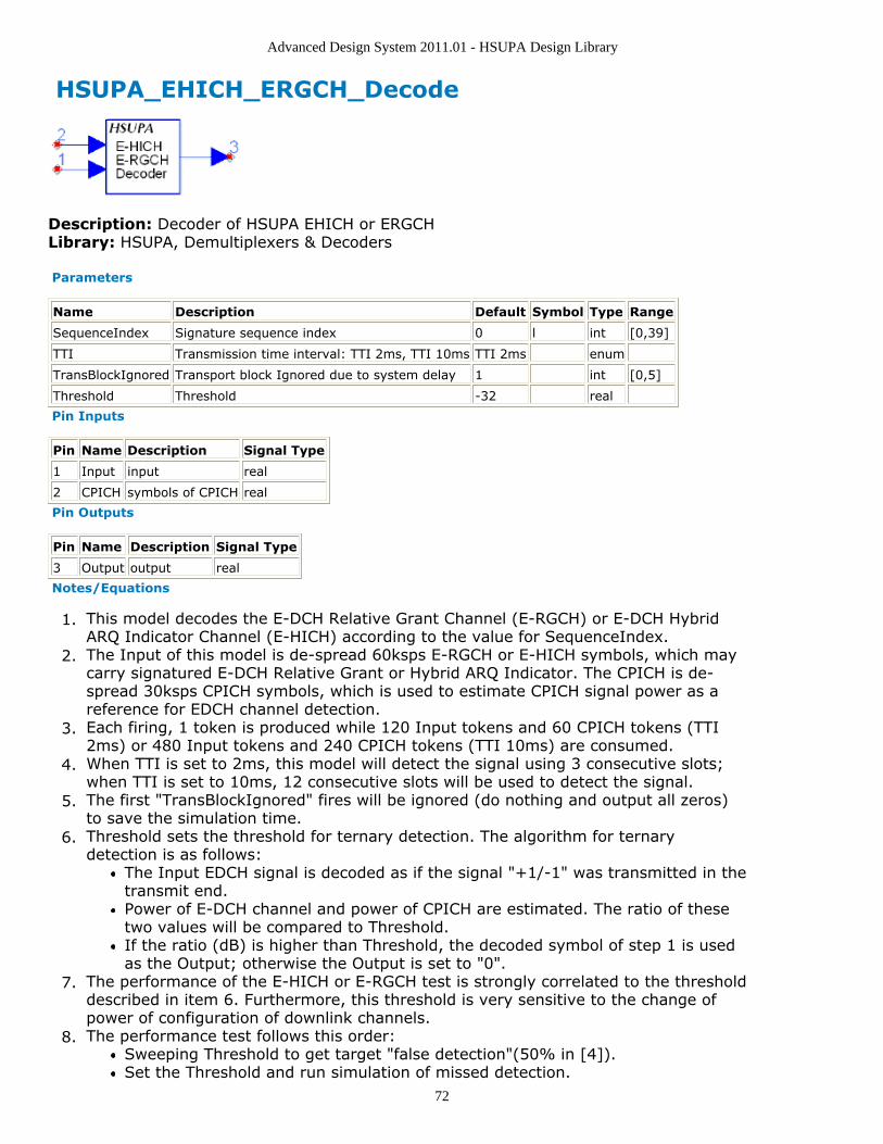
Advanced Design System 2011.01 - HSUPA Design Library
72
HSUPA_EHICH_ERGCH_Decode
Description: Decoder of HSUPA EHICH or ERGCHLibrary: HSUPA, Demultiplexers & Decoders
Parameters
Name Description Default Symbol Type Range
SequenceIndex Signature sequence index 0 l int [0,39]
TTI Transmission time interval: TTI 2ms, TTI 10ms TTI 2ms enum
TransBlockIgnored Transport block Ignored due to system delay 1 int [0,5]
Threshold Threshold -32 real
Pin Inputs
Pin Name Description Signal Type
1 Input input real
2 CPICH symbols of CPICH real
Pin Outputs
Pin Name Description Signal Type
3 Output output real
Notes/Equations
This model decodes the E-DCH Relative Grant Channel (E-RGCH) or E-DCH Hybrid1.ARQ Indicator Channel (E-HICH) according to the value for SequenceIndex.The Input of this model is de-spread 60ksps E-RGCH or E-HICH symbols, which may2.carry signatured E-DCH Relative Grant or Hybrid ARQ Indicator. The CPICH is de-spread 30ksps CPICH symbols, which is used to estimate CPICH signal power as areference for EDCH channel detection.Each firing, 1 token is produced while 120 Input tokens and 60 CPICH tokens (TTI3.2ms) or 480 Input tokens and 240 CPICH tokens (TTI 10ms) are consumed.When TTI is set to 2ms, this model will detect the signal using 3 consecutive slots;4.when TTI is set to 10ms, 12 consecutive slots will be used to detect the signal.The first "TransBlockIgnored" fires will be ignored (do nothing and output all zeros)5.to save the simulation time.Threshold sets the threshold for ternary detection. The algorithm for ternary6.detection is as follows:
The Input EDCH signal is decoded as if the signal "+1/-1" was transmitted in thetransmit end.Power of E-DCH channel and power of CPICH are estimated. The ratio of thesetwo values will be compared to Threshold.If the ratio (dB) is higher than Threshold, the decoded symbol of step 1 is usedas the Output; otherwise the Output is set to "0".
The performance of the E-HICH or E-RGCH test is strongly correlated to the threshold7.described in item 6. Furthermore, this threshold is very sensitive to the change ofpower of configuration of downlink channels.The performance test follows this order:8.
Sweeping Threshold to get target "false detection"(50% in [4]).Set the Threshold and run simulation of missed detection.

Advanced Design System 2011.01 - HSUPA Design Library
73
Compare the result of simulation with target "missed detection" (1% in [4]).There are no implementation differences between E-RGCH and E-HICH within the9.scope of this model.
References
3GPP Technical Specification TS 25.211, "Physical channels and mapping of transport1.channels onto physical channels (FDD)," Version 6.7.0, Dec. 2005.3GPP Technical Specification TS 25.212, "Multiplexing and channel coding (FDD),"2.Version 6.7.0, Dec. 2005.3GPP Technical Specification TS 25.213, "Spreading and modulation (FDD)," Version3.6.5.0, Mar. 2006.3GPP Technical Specification TS 25.101, "UE Radio transmission and Reception4.(FDD)," Version 6.11.0, Mar. 2006.

Advanced Design System 2011.01 - HSUPA Design Library
74
HSUPA_EVM
Description: HSUPA EVM measurementLibrary: HSUPA, Measurement
Parameters
Name Description Default Unit Type Range
RLoad load resistance.DefaultRLoad will inheritfrom the DF controller.
DefaultRLoad Ohm real (0,∞)
RTemp physical temperature, indegrees C, of loadresistance. DefaultRTempwill inherit from the DFcontroller.
DefaultRTemp Celsius real [-273.15,∞)
FCarrier carrier frequency 1.9 GHz Hz real (0,∞)
ChipRate symbol rate 3840000 Hz real
alpha specify the alpha for 3GPProot raised cosine filtering.
0.22 real [0,1]
LongScrambleCodeNum index of Long ScrambleCode
0 int [0,16777215]
syncModeSelection Sync mode selection:DPCCH, PRACH_MESSAGE
DPCCH enum
DPCCHSlotFormat the slot format for DPCCH,used for synchronization
0 int [0,5]
AnalysisCodeLevel specifies the channel levelthat Channel EVM with becalculated for
1 int [1,8]
AnalysisCodeIndex specifies the channel indexthat Channel EVM with becalculated for
0 int [0,2^AnalysisCodeLevel-1]
AnalysisIQPart For symbol EVM, choose IQpart for which you wouldlike calculate EVM for: I, Q,IQ
I enum
ModScheme modulation scheme forselected AnalysisCodeLeveland AnalysisCodeIndex:AutoDetect, BPSK, PAM4
AutoDetect enum
EVMLengthInSlot This variable sets chipinterval of the EVM windowin a slot, this feature wasadded to implement halfslot EVM: FullSlot,FirstHalfSlot,SecondHalfSlot
FullSlot enum
ExcludeTransient EVM metrics will excludefirst/last 96 chips from thecalculation length (normally1 slot): NO, YES
NO enum
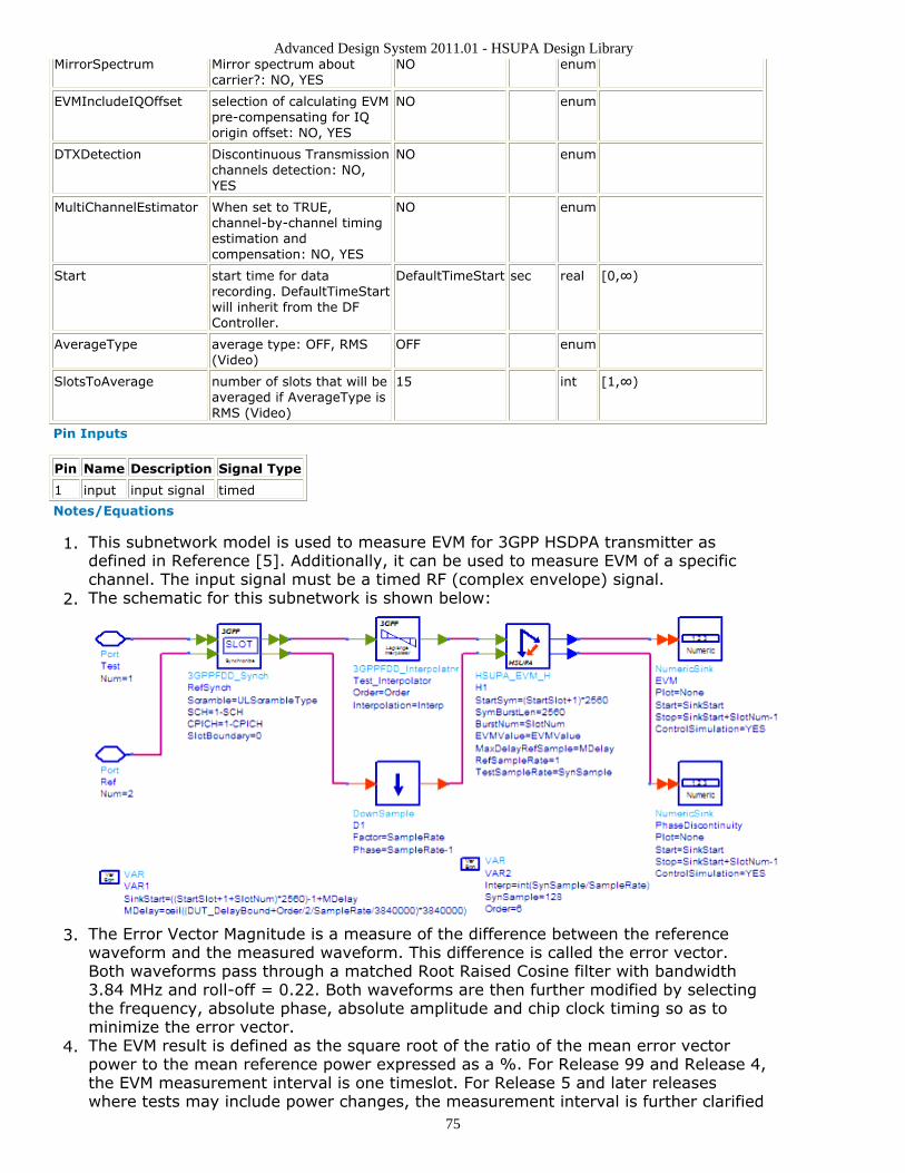
Advanced Design System 2011.01 - HSUPA Design Library
75
MirrorSpectrum Mirror spectrum aboutcarrier?: NO, YES
NO enum
EVMIncludeIQOffset selection of calculating EVMpre-compensating for IQorigin offset: NO, YES
NO enum
DTXDetection Discontinuous Transmissionchannels detection: NO,YES
NO enum
MultiChannelEstimator When set to TRUE,channel-by-channel timingestimation andcompensation: NO, YES
NO enum
Start start time for datarecording. DefaultTimeStartwill inherit from the DFController.
DefaultTimeStart sec real [0,∞)
AverageType average type: OFF, RMS(Video)
OFF enum
SlotsToAverage number of slots that will beaveraged if AverageType isRMS (Video)
15 int [1,∞)
Pin Inputs
Pin Name Description Signal Type
1 input input signal timed
Notes/Equations
This subnetwork model is used to measure EVM for 3GPP HSDPA transmitter as1.defined in Reference [5]. Additionally, it can be used to measure EVM of a specificchannel. The input signal must be a timed RF (complex envelope) signal.The schematic for this subnetwork is shown below:2.
The Error Vector Magnitude is a measure of the difference between the reference3.waveform and the measured waveform. This difference is called the error vector.Both waveforms pass through a matched Root Raised Cosine filter with bandwidth3.84 MHz and roll-off = 0.22. Both waveforms are then further modified by selectingthe frequency, absolute phase, absolute amplitude and chip clock timing so as tominimize the error vector.The EVM result is defined as the square root of the ratio of the mean error vector4.power to the mean reference power expressed as a %. For Release 99 and Release 4,the EVM measurement interval is one timeslot. For Release 5 and later releaseswhere tests may include power changes, the measurement interval is further clarified

Advanced Design System 2011.01 - HSUPA Design Library
76
as being one timeslot except when the mean power between slots is expected tochange whereupon the measurement interval is reduced by 25 µs(96 chips) at eachend of the slot.The available results from this measurement are:5.
Avg_Channel_EVM: average channel EVM rms in %Avg_Channel_MagErr_rms_percent: average channel magnitude error rms in %Avg_Channel_PhaseErr_deg: average channel phase error in degreesAvg_EVM_dB: average composite EVM rms in dBAvg_EVM_rms_percent: average composite EVM rms in %Avg_FreqErr_Hz: average frequency error in HzAvg_IQOffset_dB: average IQ offset in dBAvg_MagErr_rms_percent: average composite magnitude error rms in %Avg_PhaseErr_deg: average composite phase error in degreeAvg_Rho: average RhoChannel_EVM: channel EVM rms in % versus slotChannel_MagErr_rms_percent: channel magnitude error rms in % versus slotChannel_PhaseErr_deg: channel phase error in degree versus slotEVM_dB: composite EVM in dB versus slotEVM_rms_percent: composite EVM rms in % versus slotFreqErr_Hz: frequency error in Hz versus slotIQOffset_dB: IQ offset in dB versus slotMagErr_rms_percent: magnitude error rms in % versus slotPhaseErr_deg: phase error in degree versus slotRho: rho versus slot
When 16QAM is not used on any of the uplink code channels, the EVM shall not6.exceed 17.5% for the parameters specified in Table 6.15 in Reference [5]. When16QAM used on any of the uplink code channels, the EVM shall not exceed 14% forthe parameters specified in Table 6.15 in Reference [5].The alpha parameter specifies the alpha for 3GPP root raised cosine filtering and7.should be 0.22 in this testing.The LongScrambleCodeNum parameter specifies the long scramble code index used.8.The short scramble code is not supported yet.The syncModeSelection parameter specifies synchronization mode: DPCCH or9.PRACH_MESSAGE.The DPCCHSlotFormat specifies the slot format for DPCCH, used for synchronization.10.The AnalysisCodeLevel parameter specifies the channel level that Channel EVM with11.be calculated for. The AnalysisCodeIndex parameter specifies the channel index thatChannel EVM with be calculated for.The AnalysisIQPart specifies which part you like to calculate the EVM for, because the12.modulation is separated between I and Q ports.The ModScheme parameter specifies the modulation type for the selected code13.channel and IQ part: "BPSK", "4PAM" or you can choose "AutoDetect" to let the EVMmodel to detect the modulation type itself. However, if there exists stronginterference, the auto detect result may be wrong.The EVMLengthInSlot specifies the length of window in a slot for EVM calculation. It14.could be selected to calcualte EVM within "FullSlot", "FirstHalfSlot" or"SecondHalfSlot".The ExcludeTransient specifies whether or not to exclude the 25 µs(96 chips) at each15.end of the slot when calculating the EVM.The MirrorSpectrum parameter can be used to mirror the spectrum (invert the Q16.envelope) at the output of the modulator. Depending on the configuration of themixers in the upconverter, which typically follows a modulator, the signal at theupconverter's input may need to be mirrored. If such a configuration is used, thenthis parameter should be set to YES.The EVMIncludeIQOffset parameter specifies whether to pre-compensate for IQ origin17.offset or not when calculating EVM.

Advanced Design System 2011.01 - HSUPA Design Library
77
The DTXDetection parameter specifies whether to detect and perform correct18.measurement analysis on DTX "Discontinuous Transmission" channels. DTXmeasurement analysis mode does not affect the EVM result unless the measurementdata includes a partially transmitted frame in a channel. It is recommended that youselect YES to measure DTX signals and select NO to measure non-DTX signals.The MultiChannelEstimator parameter specifies the operation mode of the parameter19.estimator used to perform best fitting for EVM. If the MultiChannelEstimator is set toYES, channel by channel timing estimation and compensation will be performed.The Start parameter specifies the start time for data recording.20.If AverageType is set to OFF, only one slot (the first slot in the first frame) is21.detected, demodulated, and analyzed. If AverageType is set to RMS (Video),SlotsToAverage slots are processed.The SlotsToAverage parameter specifies the number of slots that will be averaged if22.AverageType is RMS Video.If, for any reason, a slot is mis-detected, the results from its analysis are discarded.23.The EVM results obtained from all the successfully slots, demodulated, and analyzedslots are averaged to give the final averaged results. The EVM results from eachsuccessfully analyzed slots are also recorded (in the variables without the Avg_ prefixin their name).This signal segment is searched in order for a complete frame including 15 slots to be24.detected. If there is an unknown idle part at the begin of the burst, then a TimedSinkcomponent can be used to plot the signal in the data display. By observing themagnitude of the signal's envelope versus time one can determine the duration of theburst and the idle interval. Making the Start parameter equals to the idle interval willfacilitate the testing.If the acquired signal segment does not contain 15 slots, the algorithm may fail to25.detect any frame and the analysis that follows will most likely produce incorrectresults. Therefore, ResultLength must be longer than 15.
References
3GPP Technical Specification TS 25.211, "Physical channels and mapping of transport1.channels onto physical channels (FDD)," Version 7.6.0, May 2008.3GPP Technical Specification TS 25.212, "Multiplexing and channel coding (FDD),"2.Version 7.9.0, Sep. 2008.3GPP Technical Specification TS 25.213, "Spreading and modulation (FDD)," Version3.7.6.0, Sep. 2008.3GPP Technical Specification TS 25.214, "Physical layer procedures (FDD)," Version4.7.9.0, May 2008.3GPP Technical Specification TS 25.101, "UE Radio transmission and Reception5.(FDD)," Version 7.13.0, Sep. 2008.3GPP Technical Specification TS 25.104, "Base Station (BS) radio transmission and6.reception (FDD)," Version 7.10.0, Mar. 2008.3GPP Technical Specification TS 25.141, "Base station (BS) conformance testing7.(FDD)," V7.11.0, Mar. 2008.3GPP Technical Specification TS 34.121, "Radio transmission and reception (FDD),"8.Version 7.5.0, Jun. 2007.
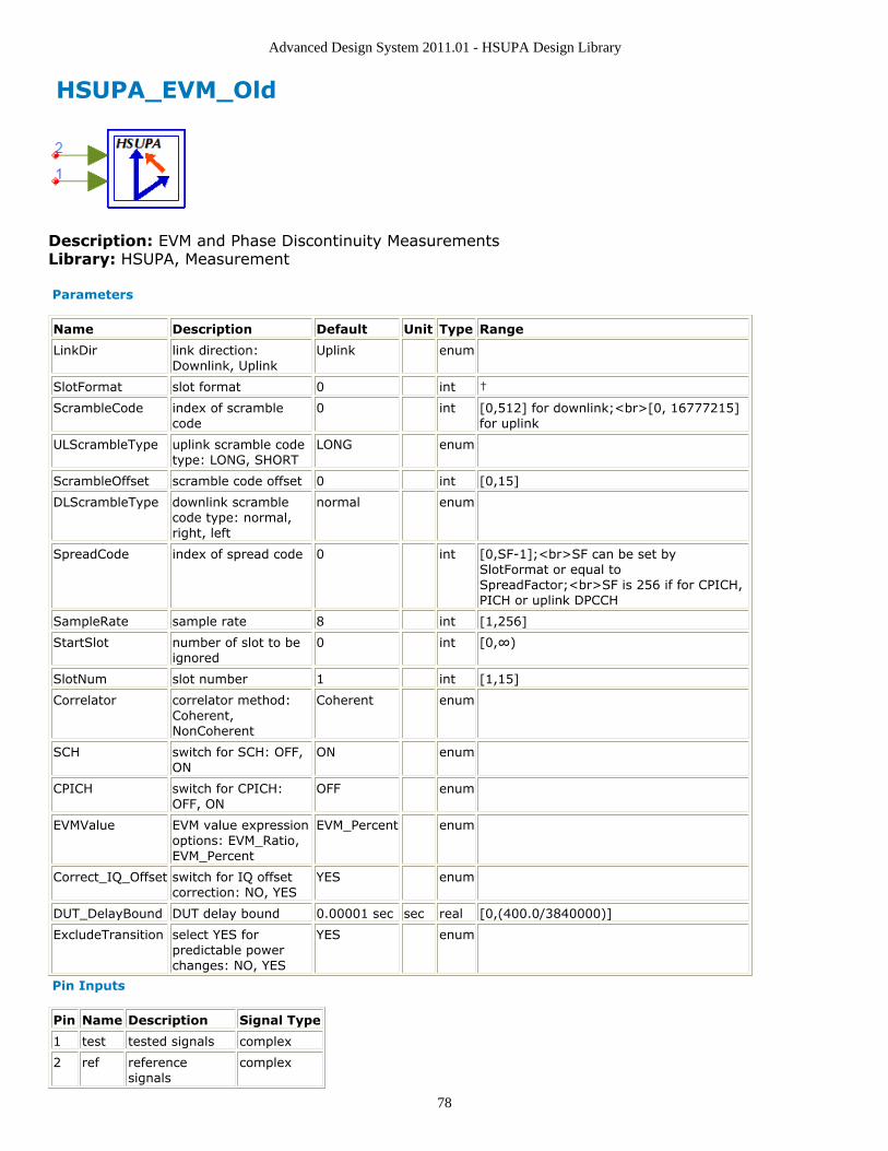
Advanced Design System 2011.01 - HSUPA Design Library
78
HSUPA_EVM_Old
Description: EVM and Phase Discontinuity MeasurementsLibrary: HSUPA, Measurement
Parameters
Name Description Default Unit Type Range
LinkDir link direction:Downlink, Uplink
Uplink enum
SlotFormat slot format 0 int †
ScrambleCode index of scramblecode
0 int [0,512] for downlink;<br>[0, 16777215]for uplink
ULScrambleType uplink scramble codetype: LONG, SHORT
LONG enum
ScrambleOffset scramble code offset 0 int [0,15]
DLScrambleType downlink scramblecode type: normal,right, left
normal enum
SpreadCode index of spread code 0 int [0,SF-1];<br>SF can be set bySlotFormat or equal toSpreadFactor;<br>SF is 256 if for CPICH,PICH or uplink DPCCH
SampleRate sample rate 8 int [1,256]
StartSlot number of slot to beignored
0 int [0,∞)
SlotNum slot number 1 int [1,15]
Correlator correlator method:Coherent,NonCoherent
Coherent enum
SCH switch for SCH: OFF,ON
ON enum
CPICH switch for CPICH:OFF, ON
OFF enum
EVMValue EVM value expressionoptions: EVM_Ratio,EVM_Percent
EVM_Percent enum
Correct_IQ_Offset switch for IQ offsetcorrection: NO, YES
YES enum
DUT_DelayBound DUT delay bound 0.00001 sec sec real [0,(400.0/3840000)]
ExcludeTransition select YES forpredictable powerchanges: NO, YES
YES enum
Pin Inputs
Pin Name Description Signal Type
1 test tested signals complex
2 ref referencesignals
complex

Advanced Design System 2011.01 - HSUPA Design Library
79
Notes/Equations
This component is obsolete for new design.Please use the improved HSUPA_EVM (hsupa) for new design work.
This subnetwork model measures EVM and Phase Discontinuity that are used to1.evaluate modulation accuracy.The schematic for this subnetwork is shown below:2.
References
3GPP Technical Specification TS 25.211, "Physical channels and mapping of transport1.channels onto physical channels (FDD)," Version 7.6.0, May 2008.3GPP Technical Specification TS 25.212, "Multiplexing and channel coding (FDD),"2.Version 7.9.0, Sep. 2008.3GPP Technical Specification TS 25.213, "Spreading and modulation (FDD)," Version3.7.6.0, Sep. 2008.3GPP Technical Specification TS 25.214, "Physical layer procedures (FDD)," Version4.7.9.0, May 2008.3GPP Technical Specification TS 25.101, "UE Radio transmission and Reception5.(FDD)," Version 7.13.0, Sep. 2008.3GPP Technical Specification TS 25.104, "Base Station (BS) radio transmission and6.reception (FDD)," Version 7.10.0, Mar. 2008.3GPP Technical Specification TS 25.141, "Base station (BS) conformance testing7.(FDD)," V7.11.0, Mar. 2008.3GPP Technical Specification TS 34.121, "Radio transmission and reception (FDD),"8.Version 7.5.0, Jun. 2007.

Advanced Design System 2011.01 - HSUPA Design Library
80
HSUPA_FRC
Description: HSUPA fixed reference channelLibrary: HSUPA, Signal Sources
Parameters
Name Description Default Type Range
FRC Fixed reference channel: FRC1, FRC2,FRC3, FRC4, FRC5, FRC6, FRC7, FRC8
FRC1 enum
TestCase Test case: E-DPDCH testing, E-DPCCHmissed detection testing, E-DPCCH falsealarm testing
E-DPDCHtesting
enum
DataPattern Source data pattern: Random, PN9, PN15,Repeat Bits
Random enum
RepeatBitValue Repeating data value 0x0001 int [0, 65535]
RepeatBitPeriod Repeating data period 2 int [1, 16]
Scramble scramble code type: LONG, SHORT LONG enum
EDPCCH_Boosting Setting to YES if E-DPCCH_Boosting isconfigured, otherwise NO: NO, YES
NO enum
ScrambleCode Index of scramble code 0 int [0,512] fordownlink;<br>[0,16777215] for uplink
Pin Inputs
Pin Name Description Signal Type
1 ARQ automatic repeat request int
Pin Outputs
Pin Name Description Signal Type
2 Output output complex
3 RSN retransmission sequencenumber
int
4 BitED bits of E-DPDCH int
5 BitEC bits of E-DPCCH int
Notes/Equations
This subnetwork is used to implement fixed reference channels for HSUPA uplink.1.The schematic of HSUPA_FRC is shown below:2.

Advanced Design System 2011.01 - HSUPA Design Library
81
Fixed reference channels are defined in Annex A.9 – A.16[5]. TTI and TransBlockSize3.vs. FRC are implemented using equations in the schematic. GainEC and GainED vs.TestCase are also implemented using equations in the schematic.DPDCH and HS-DPCCH is switched off.4.MaxRSN is set to 3.5.RV_Mode is set to "Calculated using RSN".6.HARQ_PrcssMode is set to "Depending on TTI", that is NumHARQ is 8 for TTI=2 µs7.and is 4 for TTI=10 µs.For more information on HARQ functions, please see HSUPA_Bits (hsupa) and8.HSUPA_RateMatch (hsupa).For more information, please refer to documentation for the models used in this9.subnetwork.
References
3GPP Technical Specification TS 25.211, "Physical channels and mapping of transport1.channels onto physical channels (FDD)," Version 7.6.0, May 2008.3GPP Technical Specification TS 25.212, "Multiplexing and channel coding (FDD),"2.Version 7.9.0, Sep. 2008.3GPP Technical Specification TS 25.213, "Spreading and modulation (FDD)," Version3.7.6.0, Sep. 2008.3GPP Technical Specification TS 25.104, "Base Station (BS) radio transmission and4.reception (FDD)," Version 7.10.0, Mar. 2008.3GPP Technical Specification TS 25.141, "Base station (BS) conformance testing5.(FDD)," V7.11.0, Mar. 2008.

Advanced Design System 2011.01 - HSUPA Design Library
82
HSUPA_FRC_Receiver
Description: HSUPA receiver for fixed reference channelLibrary: HSUPA, Receivers
Parameters
Name Description Default Symbol Type Range
FRC Fixed referencechannel: FRC1,FRC2, FRC3, FRC4,FRC5, FRC6, FRC7,FRC8
FRC1 enum
DPDCH_Configured Setting to YES ifDPDCH isconfigured,otherwise NO: NO,YES
NO enum
HSDPCCH_Configured Setting to YES ifHS-DPCCH isconfigured,otherwise NO: NO,YES
NO enum
Scramble scramble code type:LONG, SHORT
LONG enum
ScrambleCode Index of scramblecode
0 int [0,512] for downlink;<br>[0,16777215] for uplink
SamplesPerChip Samples per chip 8 S int [2,32]
MaxDelaySample Maximum delayboundary, in termsof samples
0 int [0,2559] for RAKEreceiver;<br>[0,102400] in othermodels
ChannelType Select the channeltype to beprocessed:CH_GAUSSIAN,CH_FADING
CH_GAUSSIAN enum
ChannelInfo Fading channelinformation source:Known, Estimated
Known enum
ChannelInfoOffset Offset betweenspread code andchannel informationin terms of sample
0 int [0,MaxDelaySample]
EstSlotsNum Number of slots forchannel estimation
1 int [1,3]
UseMovingEstWindow If use movingwindow in channelestimation: NO, YES
NO enum
PathSearch Path searchfrequency:
Once enum

Advanced Design System 2011.01 - HSUPA Design Library
83
EverySlot, Once
SearchMethod Path searchmethod: Coherent,NonCoherent,Combined
Coherent enum
SearchSlotsNum Number of slots forpath search
1 int [1,12]
PathNum Number of Rakefingers
1 int [1,6]
UsePastSearch If use past samplesfor path search: NO,YES
NO enum
PathDelaySample Delay for eachfinger, in terms ofsamples
0 intarray
[0,MaxDelaySample];<br>arraysize shall be equal to PathNum
TC_Iteration Turbo code decoderiteration number
4 int [1,10]
TC_Alfa Alfa of lowpass filter 0.4 real [0,1.0)
Threshold_EDPCCH Threshold fordecoding E-DPCCH
-23.6 real (-∞,∞)
Pin Inputs
Pin Name Description Signal Type
1 Input input complex
2 RSN retransmission sequencenumber
int
3 CH_M channel information multiple complex
Pin Outputs
Pin Name Description Signal Type
4 EDCH received bits of E-DCH int
5 GoodED CRC parity bit of EDCH packet int
6 EDPCCH received bits of E-DPCCH int
7 ActiveE E-DPCCH flag, 1 for good frame, 0 forbad
int
Notes/Equations
This subnetwork is used to implement baseband receiver for FRCs in HSUPA uplink.1.The schematic of this subnetwork is shown below:2.

Advanced Design System 2011.01 - HSUPA Design Library
84
MaxRSN is set to 3.3.RV_Mode is set to "Calculated using RSN".4.HARQ_PrcssMode is set to "Depending on TTI", that is NumHARQ is 8 for TTI=2 ms5.and is 4 for TTI=10 ms.For more information, see HSUPA_FRC (hsupa), HSUPA_UL_Rake (hsupa),6.HSUPA_RateDematch (hsupa), and HSUPA_EDPCCH_ChDecode (hsupa).
References
3GPP Technical Specification TS 25.211, "Physical channels and mapping of transport1.channels onto physical channels (FDD)," Version 7.10.0, Dec. 2008.3GPP Technical Specification TS 25.212, "Multiplexing and channel coding (FDD),"2.Version 7.9.0, Sept. 2008.3GPP Technical Specification TS 25.213, "Spreading and modulation (FDD)," Version3.7.6.0, Sept. 2008.3GPP Technical Specification TS 25.104, "UTRA (BS) FDD: Radio transmission and4.Reception," Version 7.10.0, Mar. 2008.3GPP Technical Specification TS 25.141, "Base station conformance test," Version5.7.11.0, Mar. 2008.

Advanced Design System 2011.01 - HSUPA Design Library
85
HSUPA_FRC_ReceiverRF
Description: HSUPA receiver for fixed reference channelLibrary: HSUPA, Receivers
Parameters
Name Description Default Symbol Unit Type Range
RLoad Input resistance DefaultRLoad Ohm real (0,∞)
FCarrier Carrierfrequency
1950MHz Hz real (0,∞)
Phase Reference phasein degrees
0.0 deg real (-∞,∞)
SamplesPerChip Samples perchip
8 S int [2,32]
RRC_FilterLength RRC filter length(chips)
16 int [2,128]
ScrambleCode Index ofscramble code
0 int [0,512] for downlink;<br>[0,16777215] for uplink
Scramble scramble codetype: LONG,SHORT
LONG enum
FRC Fixed referencechannel: FRC1,FRC2, FRC3,FRC4, FRC5,FRC6, FRC7,FRC8
FRC1 enum
DPDCH_Configured Setting to YES ifDPDCH isconfigured,otherwise NO:NO, YES
NO enum
HSDPCCH_Configured Setting to YES ifHS-DPCCH isconfigured,otherwise NO:NO, YES
NO enum
MaxDelaySample Maximum delayboundary, interms ofsamples
0 int [0,2559] for RAKEreceiver;<br>[0,102400] inother models
ChannelType Select thechannel type tobe processed:CH_GAUSSIAN,CH_FADING
CH_GAUSSIAN enum
ChannelInfo Fading channelinformationsource: Known,
Known enum

Advanced Design System 2011.01 - HSUPA Design Library
86
Estimated
ChannelInfoOffset Offset betweenspread code andchannelinformation interms of sample
0 int [0,MaxDelaySample]
EstSlotsNum Number of slotsfor channelestimation
1 int [1,3]
UseMovingEstWindow If use movingwindow inchannelestimation: NO,YES
NO enum
PathSearch Path searchfrequency:EverySlot, Once
Once enum
SearchMethod Path searchmethod:Coherent,NonCoherent,Combined
Coherent enum
SearchSlotsNum Number of slotsfor path search
1 int [1,12]
PathNum Number of Rakefingers
1 int [1,6]
UsePastSearch If use pastsamples for pathsearch: NO, YES
NO enum
PathDelaySample Delay for eachfinger, in termsof samples
0 intarray
[0,MaxDelaySample];<br>arraysize shall be equal to PathNum
TC_Iteration Turbo codedecoderiteration number
4 int [1,10]
TC_Alfa Alfa of lowpassfilter
0.4 real [0,1.0)
Threshold_EDPCCH Threshold fordecoding E-DPCCH
-23.6 real (-∞,∞)
Pin Inputs
Pin Name Description Signal Type
1 RF_In input timed
2 RSN retransmission sequencenumber
int
3 CH_M channel information multiple complex
Pin Outputs
Pin Name Description Signal Type
4 EDCH received bits of E-DCH int
5 GoodED CRC parity bit of EDCH packet int
6 EDPCCH received bits of E-DPCCH int
7 ActiveE E-DPCCH flag, 1 for good frame, 0 forbad
int
Notes/Equations
This subnetwork is used to implement a fixed reference channel receiver in RF for1.

Advanced Design System 2011.01 - HSUPA Design Library
87
HSUPA uplink.The schematic is shown below:2.
For more information, see HSUPA_FRC_Receiver (hsupa).3.
References
3GPP Technical Specification TS 25.211, "Physical channels and mapping of transport1.channels onto physical channels (FDD)," Version 7.10.0, Dec. 2008.3GPP Technical Specification TS 25.212, "Multiplexing and channel coding (FDD),"2.Version 7.9.0, Sept. 2008.3GPP Technical Specification TS 25.213, "Spreading and modulation (FDD)," Version3.7.6.0, Sept. 2008.3GPP Technical Specification TS 25.104, "UTRA (BS) FDD: Radio transmission and4.Reception," Version 7.10.0, Mar. 2008.3GPP Technical Specification TS 25.141, "Base station conformance test," Version5.7.11.0, Mar. 2008.
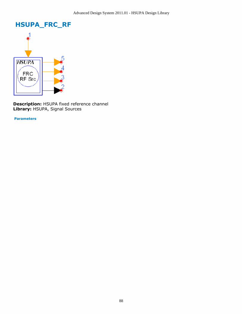
Advanced Design System 2011.01 - HSUPA Design Library
88
HSUPA_FRC_RF
Description: HSUPA fixed reference channelLibrary: HSUPA, Signal Sources
Parameters

Advanced Design System 2011.01 - HSUPA Design Library
89
Name Description Default Symbol Unit Type Range
ROut Source resistance DefaultROut Ohm real (0,∞)
RTemp Temperature DefaultRTemp Celsius real [-273.15,∞)
TStep Expression showinghow TStep is related tothe other sourceparameters
1/3.84MHz/SamplesPerChip
string
FCarrier Carrier frequency 1950MHz Hz real (0,∞)
Power Power dbmtow(24.0) W real [0,∞)
MirrorSpectrum Mirror spectrum aboutcarrier?: NO, YES
NO enum
GainImbalance Gain imbalance, Q vs I 0.0 dB real (-∞,∞)
PhaseImbalance Phase imbalance, Q vsI
0.0 deg real (-∞,∞)
I_OriginOffset I origin offset (percent) 0.0 real (-∞,∞)
Q_OriginOffset Q origin offset(percent)
0.0 real (-∞,∞)
IQ_Rotation IQ rotation 0.0 deg real (-∞,∞)
SamplesPerChip Samples per chip 8 S int [2,32]
RRC_FilterLength RRC filter length(chips)
16 int [2,128]
ScrambleCode Index of scramble code 0 int [0,512] fordownlink;<br>[0,16777215] foruplink
Scramble scramble code type:LONG, SHORT
LONG enum
FRC Fixed referencechannel: FRC1, FRC2,FRC3, FRC4, FRC5,FRC6, FRC7, FRC8
FRC1 enum
TestCase Test case: E-DPDCHtesting, E-DPCCHmissed detectiontesting, E-DPCCH falsealarm testing
E-DPDCH testing enum
DataPattern Source data pattern:Random, PN9, PN15,Repeat Bits
Random enum
RepeatBitValue Repeating data value 0x0001 int [0, 65535]
RepeatBitPeriod Repeating data period 2 int [1, 16]
EDPCCH_Boosting Setting to YES if E-DPCCH_Boosting isconfigured, otherwiseNO: NO, YES
NO enum
Pin Inputs
Pin Name Description Signal Type
1 ARQ automatic repeat request int
Pin Outputs
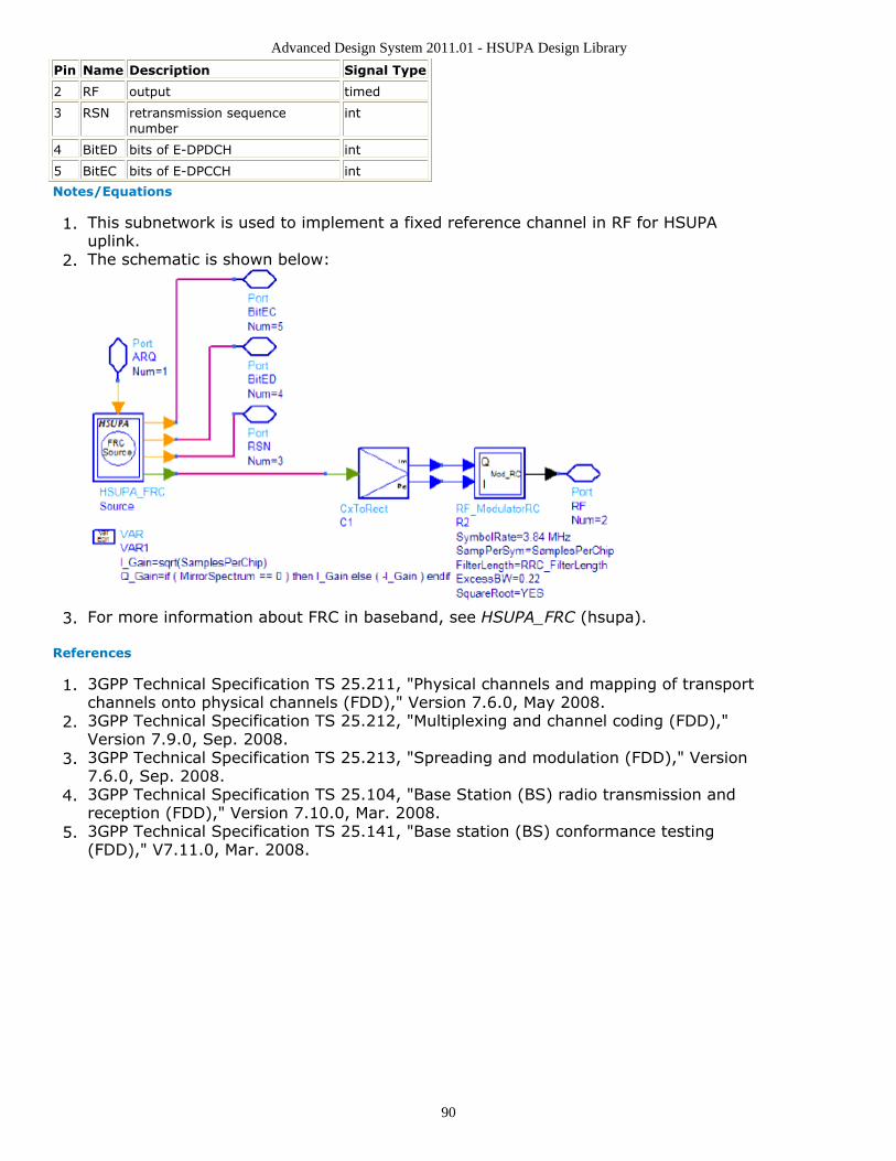
Advanced Design System 2011.01 - HSUPA Design Library
90
Pin Name Description Signal Type
2 RF output timed
3 RSN retransmission sequencenumber
int
4 BitED bits of E-DPDCH int
5 BitEC bits of E-DPCCH int
Notes/Equations
This subnetwork is used to implement a fixed reference channel in RF for HSUPA1.uplink.The schematic is shown below:2.
For more information about FRC in baseband, see HSUPA_FRC (hsupa).3.
References
3GPP Technical Specification TS 25.211, "Physical channels and mapping of transport1.channels onto physical channels (FDD)," Version 7.6.0, May 2008.3GPP Technical Specification TS 25.212, "Multiplexing and channel coding (FDD),"2.Version 7.9.0, Sep. 2008.3GPP Technical Specification TS 25.213, "Spreading and modulation (FDD)," Version3.7.6.0, Sep. 2008.3GPP Technical Specification TS 25.104, "Base Station (BS) radio transmission and4.reception (FDD)," Version 7.10.0, Mar. 2008.3GPP Technical Specification TS 25.141, "Base station (BS) conformance testing5.(FDD)," V7.11.0, Mar. 2008.

Advanced Design System 2011.01 - HSUPA Design Library
91
HSUPA_Interleaver
Description: EDCH interleaverLibrary: HSUPA, Multiplexers & Coders
Parameters
Name Description Default Symbol Type Range
EDCH_Category FDD E-DCH physical layer categories:Category 1, Category 2, Category 3,Category 4, Category 5, Category 6,Category 7
Category6
enum
TransBlockSize Transport block size 2706 L int [1,maxtransportblock size]†
TTI Transmission time interval: TTI 2ms, TTI10ms
TTI 2ms enum
PuncLimit Puncturing limit for uplink 0.468 real [PLmax , 1]‡
maxNumElement_Set0 maximum number of element in Set0 11 int [1,11]
† Please refer to table of FDD E-DCH physical layer categories.‡PLmax is 0.33 for Category 6 and is 0.44 for all other categories.
Pin Inputs
Pin Name Description Signal Type
1 Input input int
Pin Outputs
Pin Name Description Signal Type
2 Output output int
Notes/Equations
This model is used to implement channel segmentation and interleaving defined in1.4.8.5 and 4.8.6 in [2].Each firing, Ndata Output tokens are generated while Ndata Input tokens consumed.2.Determination of Ndata, spreading factor and number of E-DPDCH is described in4.8.4.1 in [2].A simple way to get the value of Ndata, spreading factor and number of E-DPDCH3.used with wanted TTI and TransBlockSize is to build and run a minimal test design ofthis model. The information will be displayed in the simulation window.
References
3GPP Technical Specification TS 25.211, "Physical channels and mapping of transport1.channels onto physical channels (FDD)," Version 7.6.0, May 2008.3GPP Technical Specification TS 25.212, "Multiplexing and channel coding (FDD),"2.Version 7.9.0, Sep. 2008.3GPP Technical Specification TS 25.213, "Spreading and modulation (FDD)," Version3.7.6.0, Sep. 2008.

Advanced Design System 2011.01 - HSUPA Design Library
92
3GPP Technical Specification TS 25.306, "UE Radio Access capabilities," Version4.7.8.0, Sep. 2008.

Advanced Design System 2011.01 - HSUPA Design Library
93
HSUPA_OCNS
Description: Flexible OCNS generatorLibrary: HSUPA, Signal Sources
Parameters
Name Description Default Type Range
DPCHNum downlink DPCHnumber
16 int [1,8] for other models;<br>[1,512] for3GPPHSUPA_OCNS and3GPPHSUPA_DPCHs
ScrambleCode index of scramblecode
0 int [0,512] for downlink;<br>[0, 16777215]for uplink
ScrambleOffset scramble code offset 0 int [0,15]
ScrambleType scramble code type:normal, right, left
normal enum
SpreadCodeArray index array ofspread codes
2 11 17 23 31 3847 55 62 69 78 8594 125 113 119
intarray
the i th element shall be in
[0,SpreadFactor[i]-1];<br>array size shallbe equal to code channelnumber;<br>codes shall be in differentOVSF code branch
DataPatternArray data pattern array:0-random, 1-PN9,2-PN15, 3-RepeatBits
0 0 0 0 0 0 0 0 00 0 0 0 0 0 0
intarray
[0,1,2,3];<br>array size shall be equal tocode channel number
RepBitValueArray bits value array tobe filled in datasequence
0 0 0 0 0 0 0 0 00 0 0 0 0 0 0
intarray
[0,255];<br>array size shall be equal tocode channel number
PowerArray channel power arrayin decibels
-1 -3 -3 -5 -2 -4 -8 -7 -4 -6 -5 -9 -10 -8 -6 0
realarray
(-∞,∞);<br>array size shall be equal tocode channel number
tDPCHOffsetArray DPCH channel offsetarray
86 134 52 45 143112 59 23 1 88 3018 30 61 128 143
intarray
[0,149];<br>array size shall be equal toDPCH channel number
SpreadFactorArray orthogonal channelspread factor array
128 128 128 128128 128 128 128128 128 128 128128 128 128 128
intarray
2 n, n=1,...,9;<br>array size shall beequal to DPCHNum
Pin Outputs
Pin Name Description Signal Type
1 out output data complex
Notes/Equations
This model is the flexible orthogonal channel noise simulator.1.Each firing, this model outputs a slot of complex chips that consists of 2560 spread2.and scrambled complex data bits.The number of dedicated channels can be set flexibly from 1 to 512. The dedicated3.channels of the OCNS signal should be evenly distributed in the code domain; timing

Advanced Design System 2011.01 - HSUPA Design Library
94
offset should be equidistantly distributed over the dedicated channels; level settingsof dedicated channels should be similar.The default OCNS model has 16 dedicated channels with channelization codes, timing4.offsets and level settings as specified in [7] for test model 1.ScrambleCode i, ScrambleOffset k, and ScrambleType parameters determine the5.scrambling code n as follows:n = (16 × i) + k + m
If ScrambleType is normal, m = 0If ScrambleType is right, m = 16384If ScrambleType is left, m = 8192
The output signal is normalized to make sure that its RMS value is 1.6.
References
3GPP Technical Specification TS 25.211, "Physical channels and mapping of transport1.channels onto physical channels (FDD)," Version 7.6.0, May 2008.3GPP Technical Specification TS 25.212, "Multiplexing and channel coding (FDD),"2.Version 7.9.0, Sep. 2008.3GPP Technical Specification TS 25.213, "Spreading and modulation (FDD)," Version3.7.6.0, Sep. 2008.3GPP Technical Specification TS 25.214, "Physical layer procedures (FDD)," Version4.7.9.0, May 2008.3GPP Technical Specification TS 25.101, "UE Radio transmission and Reception5.(FDD)," Version 7.13.0, Sep. 2008.3GPP Technical Specification TS 25.104, "Base Station (BS) radio transmission and6.reception (FDD)," Version 7.10.0, Mar. 2008.3GPP Technical Specification TS 25.141, "Base station (BS) conformance testing7.(FDD)," V7.11.0, Mar. 2008.3GPP Technical Specification TS 34.121, "Radio transmission and reception (FDD),"8.Version 7.6.0, Sep. 2007.

Advanced Design System 2011.01 - HSUPA Design Library
95
HSUPA_ParamCalc
Description: EDCH parameter calculatorLibrary: HSUPA, Multiplexers & Coders
Parameters
Name Description Default Symbol Type Range
EDCH_Category FDD E-DCH physical layer categories:Category 1, Category 2, Category 3,Category 4, Category 5, Category 6,Category 7
Category6
enum
TransBlockSize Transport block size 2706 L int [1,maxtransportblock size]†
TTI Transmission time interval: TTI 2ms, TTI10ms
TTI 2ms enum
PuncLimit Puncturing limit for uplink 0.468 real [PLmax , 1]‡
maxNumElement_Set0 maximum number of element in Set0 11 int [1,11]
† Please refer to table of FDD E-DCH physical layer categories.‡PLmax is 0.33 for Category 6 and is 0.44 for all other categories.
Pin Outputs
Pin Name Description Signal Type
1 NumED number of E-DPDCH int
2 SltF_ED slot format of E-DPDCH
int
Notes/Equations
This model is used to calculate E-DPDCH related parameters according to the setting1.of E-DCH. Each firing, one NumED and one SltF_ED tokens are produced.According to [2], the parameters of E-DPDCH such as number of E-DPDCH, slot2.format of E-DPDCH cannot be inferred easily by parameters of E-DCH such as TTI,TransBlockSize, etc. This model can help get the parameters conveniently.The number of E-DPDCH slot format are determined when determining the total3.number of bits available for the E-DCH transmission per TTI with transport format j: N
e,data,j. Ne,data,j is determined by the following variables:
The total number of bits in a TTI before rate matching with transport format j: N
e,j. The calculation for Ne,j will be described below in more detail.
The number of bits available to the CCTrCH of E-DCH type on all PhCHs: Ndata.
In the design library, Ndata are calculated as: NumOfSlots * Ndata
The results are listed in the first table below for all possible spreading factorsand BPSK modulation scheme.NumOfSlots specifies the number of slots in a TTI, NumOfSlots=3 for TTI=2ms;NumOfSlots=15 for TTI=10ms. Ndata is defined in the second table below.

Advanced Design System 2011.01 - HSUPA Design Library
96
The set of Ne,data values allowed by the UTRAN and supported by the UE:SET0.So for TTI=2ms, SET0 can be a subset of{30,60,120,240,480,960,1920,3840,7680,11520}For TTI=10ms, SET0 can be a subset of {150,300,600,1200,2400,4800,9600,19200, 38400, 57600}.TTI defined by parameter TTI.PLnon-max defined by parameter PuncLimit.PLmax For BPSK modulation, PLmax =0.44 for E-DCH Category 1,2,3,4,5, andPLmax = 0.33 for E-DCH Category 6.PLmod,switch is equal to 0.468
Ne,data,j is determined by an algorithm as illustrated in the pseudocode example4.below:

Advanced Design System 2011.01 - HSUPA Design Library
97
Since the Ne,data,j is determined, the number of E-DPDCH and the Spread Factor can5.
be determined by the preceding table. The slot format can be determined by SF bythe following table:
Calculation for Ne,j: Ne,j specifies the total number of bits in a TTI before rate6.

Advanced Design System 2011.01 - HSUPA Design Library
98
matching with transport format j and is calculated as:Ne,j = codeBlkNum * chCodedSize, where, codeBlkNum refers to the number of
code block segmentation and calculated as: *codeBlkNum =ceil((TransBlockSize + Ncrc) / Z), Where Ncrc refer to the size of CRC, and fixedto 24 for E-DCH, Z refers to the maximum code block size and Z = 5114 for E-DCH (turbo coding).chCodedSize refers to number of bits in each code block after encoding andcalculated as: chCodedSize = 3 * codeBlkSize + 12codeBlkSize refers to number of bits in each code block before encoding andcalculated as:
if (TransBlockSize + Ncrc) < 40codeBlkSize = 40elsecodeBlkSize = ceil((TransBlockSize + Ncrc) / codeBlkNum)
References
3GPP Technical Specification TS 25.211, "Physical channels and mapping of transport1.channels onto physical channels (FDD)," Version 6.7.0, Dec. 2005.3GPP Technical Specification TS 25.212, "Multiplexing and channel coding (FDD),"2.Version 6.7.0, Dec. 2005.3GPP Technical Specification TS 25.213, "Spreading and modulation (FDD)," Version3.6.5.0, Mar. 2006.

Advanced Design System 2011.01 - HSUPA Design Library
99
HSUPA_PhCH_Demap
Description: EDCH physical channel demapperLibrary: HSUPA, Demultiplexers & Decoders
Parameters
Name Description Default Symbol Type Range
EDCH_Category FDD E-DCH physical layer categories:Category 1, Category 2, Category 3,Category 4, Category 5, Category 6,Category 7
Category6
enum
TransBlockSize Transport block size 2706 L int [1,maxtransportblock size]†
TTI Transmission time interval: TTI 2ms, TTI10ms
TTI 2ms enum
PuncLimit Puncturing limit for uplink 0.468 real [PLmax , 1]‡
maxNumElement_Set0 maximum number of element in Set0 11 int [1,11]
† Please refer to table of FDD E-DCH physical layer categories.‡PLmax is 0.33 for Category 6 and is 0.44 for all other categories.
Pin Inputs
Pin Name Description Signal Type
1 InputM data for physical channel(s) multiple real
Pin Outputs
Pin Name Description Signal Type
2 Output output real
Notes/Equations
This model is used to implement physical channel demapping for HSUPA uplink.1.Each firing, Ndata Output tokens are generated while 7680 InputM tokens are2.consumed if TTI=2ms is used, or 38400 InputM tokens are consumed if TTI=10ms isused. Determination of Ndata, spreading factor and number of E-DPDCH is describedin 4.8.4.1 in [2].A simple way to get the value of Ndata, spreading factor and number of E-DPDCH3.used with wanted TTI and TransBlockSize is to build and run a minimal test design ofthis model. The information will be displayed in the simulation window.The model is the converse of model HSUPA_PhCH_Map. For more information, see4.HSUPA_PhCH_Map (hsupa).All "spreading factor" input chips in each physical channel are averaged to get the5.symbols. The symbols are then combined to recover the transport channel block.
References
3GPP Technical Specification TS 25.211, "Physical channels and mapping of transport1.channels onto physical channels (FDD)," Version 6.7.0, Dec. 2005.

Advanced Design System 2011.01 - HSUPA Design Library
100
3GPP Technical Specification TS 25.212, "Multiplexing and channel coding (FDD),"2.Version 6.7.0, Dec. 2005.3GPP Technical Specification TS 25.213, "Spreading and modulation (FDD)," Version3.6.5.0, Mar. 2006.

Advanced Design System 2011.01 - HSUPA Design Library
101
HSUPA_PhCH_Map
Description: EDCH physical channel mapperLibrary: HSUPA, Multiplexers & Coders
Parameters
Name Description Default Symbol Type Range
EDCH_Category FDD E-DCH physical layer categories:Category 1, Category 2, Category 3,Category 4, Category 5, Category 6,Category 7
Category6
enum
TransBlockSize Transport block size 2706 L int [1,maxtransportblock size]†
TTI Transmission time interval: TTI 2ms, TTI10ms
TTI 2ms enum
PuncLimit Puncturing limit for uplink 0.468 real [PLmax , 1]‡
maxNumElement_Set0 maximum number of element in Set0 11 int [1,11]
† Please refer to table of FDD E-DCH physical layer categories.‡PLmax is 0.33 for Category 6 and is 0.44 for all other categories.
Pin Inputs
Pin Name Description Signal Type
1 Input input int
Pin Outputs
Pin Name Description Signal Type
2 OutputM data for physical channel(s) multiple real
Notes/Equations
This model is used to map the interleaved data into each physical channel defined in1.4.8.7 in [2].Each firing, 7680 OutputM tokens are generated if TTI=2ms is used, or 384002.OutputM tokens are generated if TTI=10ms is used while Ndata Input tokenconsumed. Determination of Ndata, spreading factor and number of E-DPDCH isdescribed in 4.8.4.1 in [2].A simple way to get the value of Ndata, spreading factor, and number of E-DPDCH3.used with wanted TTI and TransBlockSize is to build and run a minimal test design ofthis model. The information will be displayed in the simulation window.Since synchronous data flow is employed, the input and output token involved in4.each firing are fixed. But the number of data for OutputM is different if the spreadingfactor is different. Since the chip rate after spreading is the same for all codechannels, a convenient way to resolve this issue is just to repeat the data fromsymbol rate to chip rate. This way, when spreading code channels, the signal will bemultiplied with spreading code directly.The bus width of OuputM is the number of E-DPDCH.5.If the number of E-DPDCH is 2, the spreading factor for the two channels are the6.

Advanced Design System 2011.01 - HSUPA Design Library
102
same and can only be 4 or 2. If the number of E-DPDCH is 4, the first two channelsuse spreading code Cch,2,1 and the last two channels use spreading code Cch,4,1 .
References
3GPP Technical Specification TS 25.211, "Physical channels and mapping of transport1.channels onto physical channels (FDD)," Version 6.7.0, Dec. 2005.3GPP Technical Specification TS 25.212, "Multiplexing and channel coding (FDD),"2.Version 6.7.0, Dec. 2005.3GPP Technical Specification TS 25.213, "Spreading and modulation (FDD)," Version3.6.5.0, Mar. 2006.

Advanced Design System 2011.01 - HSUPA Design Library
103
HSUPA_RateDematch
Description: EDCH rate dematcherLibrary: HSUPA, Demultiplexers & Decoders
Parameters
Name Description Default Symbol Type Range
EDCH_Category FDD E-DCH physical layer categories:Category 1, Category 2, Category 3,Category 4, Category 5, Category 6,Category 7
Category 6 enum
TransBlockSize Transport block size 2706 L int [1,maxtransportblock size]†
TTI Transmission time interval: TTI 2ms, TTI10ms
TTI 2ms enum
PuncLimit Puncturing limit for uplink 0.468 real [PLmax , 1]‡
RV_Mode Redundancy version mode: Calculatedusing RSN, Only index 0
Calculatedusing RSN
enum
MaxRSN Maximum retransmission sequencenumber
3 int [0,3]
HARQ_PrcssMode Way to setting number of HARQ:Depending on TTI, User defined
Dependingon TTI
enum
NumHARQ Number of HARQ processes 4 int [2,8]
maxNumElement_Set0 maximum number of element in Set0 11 int [1,11]
TransBlockIgnored Transport block Ignored due to systemdelay
1 int [0,5]
LLR_Bypass Bypass LLR Combination or not: NO, YES NO enum
† Please refer to table of FDD E-DCH physical layer categories.‡PLmax is 0.33 for Category 6 and is 0.44 for all other categories.
Pin Inputs
Pin Name Description Signal Type
1 Input input real
2 RSN retransmission sequencenumber
int
Pin Outputs
Pin Name Description Signal Type
3 Output output real
Notes/Equations
This model is used to implement rate dematch for HSUPA uplink.1.Each firing, ((TransBlockSize + number of padding bits) * 3 + code block number *2.12) Output tokens are generated while Ndata Input tokens are consumed.Determination of Ndata, spreading factor, and number of E-DPDCH is described in4.8.4.1 in [2].

Advanced Design System 2011.01 - HSUPA Design Library
104
A simple way to get the value of code block number, code block size and the number3.of padding bits and their relationship with the value of TransBlockSize is just to runthe model HSUPA_CodeBlkSeg with wanted TransBlockSize in a minimal runnabledesign. The information will then be displayed in the simulation window.A simple way to get the value of Ndata, spreading factor and number of E-DPDCH4.used with wanted TTI and TransBlockSize is to build and run a minimal test design ofthis model. The information will be displayed in the simulation window.This model implements the converse operation of HSUPA_RateMatch. For more5.information, see HSUPA RateMatch (hsupa).The received signal for each HARQ process is buffered in this model. If the input of6.RSN is 0, current input data will be stored into the buffer of the current HARQprocess directly. If the input of RSN is larger than 0, it means the received signal is aredundancy version and there is a previous version stored in the buffer of the currentHARQ process. Versions of received signal are combined and then stored into thebuffer of the current HARQ process. The data in the buffer for the current HARQprocess are then fed into channel decoder(s).Since the soft combination described above depends on HARQ process and rate7.dematch is implemented TTI by TTI, the beginning of the first HARQ process must beknown to the model. Generally, receiver may introduce some delays into datastream. The value of delay shall be sent to this model by setting parameterTransBlockIgnored.
References
3GPP Technical Specification TS 25.211, "Physical channels and mapping of transport1.channels onto physical channels (FDD)," Version 7.10.0, Dec. 2008.3GPP Technical Specification TS 25.212, "Multiplexing and channel coding (FDD),"2.Version 7.9.0, Sept. 2008.3GPP Technical Specification TS 25.213, "Spreading and modulation (FDD)," Version3.7.6.0, Sept. 2008.

Advanced Design System 2011.01 - HSUPA Design Library
105
HSUPA_RateMatch
Description: EDCH rate matcherLibrary: HSUPA, Multiplexers & Coders
Parameters
Name Description Default Symbol Type Range
EDCH_Category FDD E-DCH physical layer categories:Category 1, Category 2, Category 3,Category 4, Category 5, Category 6,Category 7
Category 6 enum
TransBlockSize Transport block size 2706 L int [1,maxtransportblock size]†
TTI Transmission time interval: TTI 2ms, TTI10ms
TTI 2ms enum
PuncLimit Puncturing limit for uplink 0.468 real [PLmax , 1]‡
RV_Mode Redundancy version mode: Calculatedusing RSN, Only index 0
Calculatedusing RSN
enum
MaxRSN Maximum retransmission sequencenumber
3 int [0,3]
HARQ_PrcssMode Way to setting number of HARQ:Depending on TTI, User defined
Dependingon TTI
enum
NumHARQ Number of HARQ processes 4 int [2,8]
maxNumElement_Set0 maximum number of element in Set0 11 int [1,11]
† Please refer to table of FDD E-DCH physical layer categories.‡PLmax is 0.33 for Category 6 and is 0.44 for all other categories.
Pin Inputs
Pin Name Description Signal Type
1 Input input int
2 RSN retransmission sequencenumber
int
Pin Outputs
Pin Name Description Signal Type
3 Output output int
Notes/Equations
This model is used to implement rate match defined in 4.8.4 in [2] for HSUPA uplink1.Each firing, Ndata Output tokens are generated while ((TransBlockSize + number of2.padding bits) * 3 + code block number * 12) Input tokens consumed. Determinationof Ndata, spreading factor, and number of E-DPDCH is described in 4.8.4.1 in [2].A simple way to get the value of code block number, code block size, and the number3.of padding bits and their relationship with the value of TransBlockSize is to run themodel HSUPA_CodeBlkSeg with wanted TransBlockSize in a minimal runnable design.The information will then be displayed in the simulation window.

Advanced Design System 2011.01 - HSUPA Design Library
106
A simple way to get the value of Ndata, spreading factor, and number of E-DPDCH4.used with wanted TTI and TransBlockSize is to build and run a minimal test design ofthis model. The information will be displayed in the simulation window.If the value of RV_Mod is set to "Calculated using RSN", the RSN input, the5.NumHARQ value, and current TTI number will be used to calculate the RV valueaccording to Table 16 of Relation between RSN value and E-DCH RV Index in 4.9.2.2in [2].The table shows the Relation between RSN value and E-DCH RV Index. If6.HARQ_PrcssMode is set to "Depending on TTI", NumHARQ is set to 8 for TTI 2ms and4 for TTI 10 ms. Otherwise, the user can set the value of NumHARQ. N sys / N e,data,j <1/2 1/2 = N sys / N e,data,j
RSN Value E-DCH RV Index E-DCH RV Index
0 0 0
1 2 3
2 0 2
3 [ ÎTTIN/N ARQ ° mod 2 ] x 2 ÎTTIN/N ARQ ° mod 4
The process of bit separation, rate match with specific RV value, and bit collection7.can be found in 4.8.4.2-4.8.4.4 in [2].
References
3GPP Technical Specification TS 25.211, "Physical channels and mapping of transport1.channels onto physical channels (FDD)," Version 7.6.0, May 2008.3GPP Technical Specification TS 25.212, "Multiplexing and channel coding (FDD),"2.Version 7.9.0, Sep. 2008.3GPP Technical Specification TS 25.213, "Spreading and modulation (FDD)," Version3.7.6.0, Sep. 2008.

Advanced Design System 2011.01 - HSUPA Design Library
107
HSUPA_RF_EVM
Description: EVM and Phase Discontinuity MeasurementsLibrary: HSUPA, Measurement
Parameters
Name Description Default Unit Type Range
RLoad input resistance DefaultROut Ohm real (0,∞)
RTemp temperature of resistor,in celsius
DefaultRTemp real [-273.15,∞)
ExcessBW excess bandwidth ofraised cosine filters
0.22 real (0.0,1.0)
FilterLength length of raised cosinefilters in number ofsymbols
16 int [1,∞]
SamplesPerChip samples per chip 8 int [1,256]
LinkDir link direction: Downlink,Uplink
Uplink enum
ScrambleCode index of scramble code 0 int [0,511] fordownlink;<br>[0,16777215] foruplink
ULScrambleType uplink scramble codetype: LONG, SHORT
LONG enum
ScrambleOffset scramble offset indownlink channels
0 int [0,15]
DLScrambleType downlink scramble codetype: Normal,RightAlternate,LeftAlternate
Normal enum
SpreadCode index of spread code 0 int [0,255] for uplink DPCCH;<br>[0,SF-1] for downlink;<br>SF is set bySlotFormat
SlotFormat slot format 0 int [0,5] for uplink DPCCH;<br>[0,16 ]for downlink DPCH
StartSlot number of slot to beignored
0 int [0,∞)
SlotNum number of slotsmeasured
2 int [1,15]
SCH switch for SCH: OFF, ON ON enum
CPICH switch for CPICH: OFF,ON
OFF enum
DUT_DelayBound Search length 0.00001 sec sec real (0,(400.0/3840000))
EVMValue EVM value expressionoptions: EVM_Ratio,EVM_Percent
EVM_Percent enum
Correct_IQ_Offset switch for IQ offsetcorrection: NO, YES
YES enum
ExcludeTransition select YES forpredictable powerchanges: NO, YES
YES enum

Advanced Design System 2011.01 - HSUPA Design Library
108
Pin Inputs
Pin Name Description Signal Type
1 RFin input RF signal timed
2 ref referencesignals
complex
Notes/Equations
This component is obsolete for new design.Please use the improved HSUPA_EVM (hsupa) for new design work.
This subnetwork model measures EVM and Phase Discontinuity that are used to1.evaluate modulation accuracy.The schematic for this subnetwork is shown below.
References
3GPP Technical Specification TS 25.211, "Physical channels and mapping of transport1.channels onto physical channels (FDD)," Version 7.6.0, May 2008.3GPP Technical Specification TS 25.212, "Multiplexing and channel coding (FDD),"2.Version 7.9.0, Sep. 2008.3GPP Technical Specification TS 25.213, "Spreading and modulation (FDD)," Version3.7.6.0, Sep. 2008.3GPP Technical Specification TS 25.214, "Physical layer procedures (FDD)," Version4.7.9.0, May 2008.3GPP Technical Specification TS 25.101, "UE Radio transmission and Reception5.(FDD)," Version 7.13.0, Sep. 2008.3GPP Technical Specification TS 25.104, "Base Station (BS) radio transmission and6.reception (FDD)," Version 7.10.0, Mar. 2008.3GPP Technical Specification TS 25.141, "Base station (BS) conformance testing7.(FDD)," V7.11.0, Mar. 2008.3GPP Technical Specification TS 34.121, "Radio transmission and reception (FDD),"8.Version 7.5.0, Jun. 2007.

Advanced Design System 2011.01 - HSUPA Design Library
109
HSUPA_RF_OutputPower
Description: HSUPA output power measurementsLibrary: HSUPA, Measurement
Parameters
Name Description Default Symbol Unit Type Range
RLoad Input resistance DefaultRLoad Ohm real (0,∞)
FCarrier Carrier frequency 1950MHz Hz real (0,∞)
SamplesPerChip Samples per chip 8 S int [2,32]
ScrambleCode Index of scramble code 0 int [0,512] for downlink;<br>[0,16777215] for uplink
Scramble scramble code type:LONG, SHORT
LONG enum
SlotFormat Slot format 0 int [0,5] for uplink DPCCH
CM_k Slope factor forcalculating cubic metric
1.56 real [1.0,3.0]
SearchLength Search length .00001 sec sec real (0,(400.0/3840000))
StartSlot number of slot to beignored
0 int [0,∞)
SlotNum number of slotsmeasured
1 int [1,30]
Pin Inputs
Pin Name Description Signal Type
1 RF_In input timed
2 Ref input complex
Notes/Equations
This model is used to calculate output power and cubic metrics.1.The average period is one slot; SlotNum specifies the number of slots to be2.measured.Test signals are aligned at the specified slot boundary to ensure that the power3.average is based on a single slot.The schematic for this subnetwork is shown below:4.
Cubic Metric (CM) is based on the UE transmit channel configuration and is given by5.
Advanced Design System 2011.01 - HSUPA Design Library
110
CM =CEIL{\ [20 * log10 ((v_norm 3) rms ) - 20 * log10 ((v_norm_ref 3) rms )] / k,
0.5} where:CEIL{ x, 0.5 } means rounding upwards to closest 0.5dB, i.e. CMŒ[0, 0.5, 1.0,1.5, 2.0, 2.5, 3.0, 3.5]k is 1.85 for signals where all channelisation codes meet the following criteria C
SF, N where N < SF/2
k is 1.56 for signals where any channelisation code meet the following criteria C
SF, N where N ≥ SF/2
v_norm_ref is the normalized voltage waveform of the reference signal (12.2kbps AMR Speech) and 20 * log10 ((v_norm_ref 3) rms is 1.5237 dB.
MPR equals the larger value of CM-1 and 0.6.For more information, see 3GPPFDD_Synch (wcdma3g) and WCDMA3G_RF_PowMeas7.(wcdma3g) in the 3GPP W-CDMA Design Library (wcdma3g) documentation.
References
3GPP Technical Specification TS 25.211, "Physical channels and mapping of transport1.channels onto physical channels (FDD)," Version 6.7.0, Dec. 2005.3GPP Technical Specification TS 25.212, "Multiplexing and channel coding (FDD),"2.Version 6.7.0, Dec. 2005.3GPP Technical Specification TS 25.213, "Spreading and modulation (FDD)," Version3.6.5.0, Mar. 2006.3GPP Technical Specification TS 25.101, "UE Radio transmission and Reception4.(FDD)," Version 6.11.0, Mar. 2006.

Advanced Design System 2011.01 - HSUPA Design Library
111
HSUPA_SignatureSqn
Description: HSUPA signature sequence generatorLibrary: HSUPA, Multiplexers & Coders
Parameters
Name Description Default Symbol Type Range
SequenceIndex Signature sequenceindex
0 l int [0,39]
Pin Outputs
Pin Name Description Signal Type
1 Output output real
Notes/Equations
This model generates the E-DCH Relative Grant Channel (E-RGCH) or the E-DCH1.Hybrid ARQ Indicator Channel (E-HICH) signature sequence according toSequenceIndex as defined in [1].Each firing, one token is produced.2.The orthogonal signature sequences Css,40,m(i) is given by the following table and3.the index m(i) in slot i is given by E-HICH and E-RGCH signature hopping pattern.
E-RGCH and E-HICH Signature Sequences
Css,40,0 -1
-1
-1
1 -1
1 -1
-1
1 1 -1
-1
1 -1
1 1 -1
1 1 -1
-1
-1
-1
-1
-1
-1
-1
1 -1
1 -1
-1
1 1 1 1 1 -1
-1
-1
Css,40,1 -1
1 1 -1
-1
1 1 1 -1
-1
1 -1
1 1 -1
-1
-1
-1
1 1 1 -1
-1
-1
-1
1 -1
-1
-1
-1
-1
-1
-1
1 1 -1
1 1 -1
-1
Css,40,2 -1
-1
-1
1 -1
1 1 1 -1
-1
-1
-1
1 -1
-1
1 1 -1
-1
1 1 -1
1 1 1 -1
-1
1 1 1 -1
1 -1
-1
-1
-1
-1
-1
-1
-1
Css,40,3 1 -1
-1
-1
-1
-1
-1
1 1 1 -1
1 -1
1 -1
1 -1
-1
1 1 -1
1 -1
-1
1 1 -1
1 -1
-1
1 1 -1
-1
1 -1
-1
-1
-1
-1
Css,40,4 1 1 1 -1
-1
1 -1
1 -1
-1
1 1 1 -1
1 1 1 1 1 1 -1
1 1 1 -1
-1
-1
1 1 -1
1 -1
1 -1
1 1 -1
1 -1
-1
Css,40,5 -1
1 -1
-1
1 1 1 -1
1 1 -1
1 1 1 -1
1 1 1 -1
-1
1 -1
-1
1 -1
1 -1
1 -1
-1
1 -1
1 -1
-1
-1
-1
1 1 -1
Css,40,6 1 1 -1
-1
-1
1 1 -1
1 1 -1
-1
1 -1
-1
-1
-1
1 1 -1
1 1 1 -1
1 -1
1 -1
1 -1
-1
1 1 -1
1 -1
-1
1 -1
1
Css,40,7 -1
1 -1
1 1 1 -1
-1
-1
-1
-1
1 1 1 1 -1
-1
-1
1 -1
-1
-1
1 -1
1 1 -1
-1
1 1 1 1 -1
-1
1 1 -1
1 1 -1
Css,40,8 1 1 -1
1 1 -1
1 1 1 1 -1
-1
-1
-1
1 -1
1 -1
1 1 1 1 -1
1 -1
-1
-1
-1
-1
1 -1
-1
-1
-1
1 1 -1
1 1 -1
Css,40,9 -1
1 -1
-1
-1
-1
1 -1
-1
-1
-1
1 -1
-1
1 1 1 -1
1 -1
1 -1
-1
1 1 -1
1 1 -1
-1
1 1 -1
1 1 1 1 1 -1
1
Css,40,10 -1
1 1 -1
1 1 -1
1 1 1 1 -1
1 -1
1 1 -1
-1
-1
1 -1
-1
-1
-1
1 -1
1 1 -1
-1
-1
1 -1
-1
-1
1 -1
1 1 1

Advanced Design System 2011.01 - HSUPA Design Library
112
Css,40,11 -1
1 -1
-1
-1
-1
-1
1 1 1 -1
-1
-1
1 1 -1
1 1 -1
1 -1
-1
1 1 1 1 -1
-1
1 -1
-1
1 1 1 -1
1 1 1 -1
-1
Css,40,12 -1
-1
-1
-1
1 -1
1 1 -1
-1
-1
-1
-1
1 1 1 -1
1 1 1 1 -1
1 -1
-1
1 1 1 1 -1
-1
-1
1 -1
1 1 -1
-1
1 1
Css,40,13 1 1 1 1 -1
-1
1 -1
-1
-1
1 -1
-1
1 1 1 -1
1 -1
-1
1 1 -1
-1
1 1 -1
1 -1
1 -1
1 1 -1
-1
1 -1
1 -1
-1
Css,40,14 -1
1 1 1 -1
-1
-1
-1
1 1 1 -1
-1
1 -1
1 1 -1
1 -1
-1
-1
1 1 -1
1 1 1 1 1 -1
-1
-1
-1
1 -1
-1
1 -1
1
Css,40,15 -1
-1
1 1 -1
1 1 1 1 1 1 1 1 1 1 -1
1 1 1 1 1 -1
-1
1 1 1 1 -1
-1
1 1 1 1 -1
1 1 -1
-1
-1
1
Css,40,16 1 -1
-1
-1
-1
1 -1
-1
-1
-1
-1
-1
1 1 1 -1
1 -1
-1
-1
-1
1 -1
1 -1
1 1 -1
-1
-1
-1
-1
-1
-1
-1
1 -1
-1
-1
1
Css,40,17 1 -1
1 -1
1 1 1 -1
1 1 1 -1
1 1 1 1 1 -1
1 -1
1 1 1 1 1 1 -1
1 1 -1
-1
1 -1
1 1 1 1 -1
1 -1
Css,40,18 1 1 -1
1 -1
1 1 1 1 1 -1
1 1 1 1 1 -1
-1
-1
1 1 1 1 -1
-1
1 1 1 1 1 1 -1
-1
1 -1
1 1 1 -1
1
Css,40,19 1 1 -1
1 1 1 -1
1 -1
-1
-1
-1
1 1 -1
1 1 1 1 1 -1
1 -1
1 1 1 1 1 -1
1 -1
1 1 1 1 -1
1 1 1 1
Css,40,20 1 1 1 -1
1 1 -1
1 -1
1 -1
1 -1
-1
-1
1 -1
-1
1 -1
1 -1
-1
1 1 1 1 -1
1 1 -1
-1
1 1 -1
1 -1
-1
-1
-1
Css,40,21 -1
1 1 -1
-1
-1
-1
1 -1
1 -1
-1
1 -1
-1
1 1 -1
-1
-1
1 1 1 -1
-1
1 -1
-1
-1
1 1 1 1 -1
1 1 1 -1
1 1
Css,40,22 -1
-1
-1
1 -1
-1
-1
1 -1
1 1 -1
1 1 -1
-1
-1
-1
1 -1
1 1 -1
1 1 -1
-1
1 1 -1
1 -1
1 1 -1
1 -1
1 1 1
Css,40,23 1 -1
-1
-1
-1
1 1 1 1 -1
1 1 -1
-1
-1
-1
1 -1
-1
-1
-1
-1
1 -1
1 1 -1
1 -1
1 -1
-1
1 1 1 1 -1
1 1 1
Css,40,24 -1
-1
-1
1 1 1 -1
-1
1 -1
1 -1
-1
-1
-1
1 1 -1
1 1 1 1 1 -1
1 1 1 -1
-1
-1
1 -1
1 -1
-1
1 1 1 -1
-1
Css,40,25 -1
1 -1
-1
1 -1
-1
-1
1 -1
1 1 1 -1
-1
-1
-1
1 1 1 1 1 1 1 -1
1 -1
1 -1
1 -1
1 -1
1 -1
1 -1
-1
-1
1
Css,40,26 -1
-1
1 1 1 1 1 1 -1
1 -1
1 -1
-1
1 -1
-1
-1
1 -1
-1
1 1 1 -1
1 -1
1 -1
-1
-1
1 1 -1
-1
-1
1 1 -1
1
Css,40,27 1 -1
1 -1
-1
1 -1
1 1 -1
-1
-1
-1
1 -1
-1
-1
1 1 -1
1 -1
1 1 -1
-1
1 1 -1
1 1 1 -1
-1
-1
1 1 1 1 -1
Css,40,28 1 1 -1
1 1 1 -1
1 1 -1
1 -1
-1
1 1 1 -1
-1
-1
-1
1 -1
1 1 -1
-1
-1
-1
-1
-1
1 1 1 1 1 -1
-1
-1
-1
1
Css,40,29 -1
1 -1
-1
-1
1 -1
-1
-1
1 1 1 -1
1 1 -1
-1
-1
-1
1 1 1 1 1 1 -1
1 1 -1
1 -1
-1
1 -1
1 -1
1 -1
1 -1
Css,40,30 -1
1 1 -1
1 -1
1 1 1 -1
-1
-1
1 1 1 -1
1 -1
1 -1
-1
1 1 -1
1 -1
1 1 -1
1 1 -1
1 1 -1
-1
-1
-1
-1
-1
Css,40,31 -1
1 -1
-1
-1
1 1 1 1 -1
1 -1
-1
-1
1 1 -1
1 1 -1
-1
1 -1
1 1 1 -1
-1
1 1 1 -1
-1
-1
-1
-1
1 -1
1 1
Css,40,32 1 1 1 1 -1
-1
1 -1
1 -1
-1
1 1 1 -1
1 -1
-1
1 1 -1
-1
1 1 1 -1
-1
-1
-1
-1
-1
-1
1 -1
-1
1 1 -1
1 1
Css,40,33 -1
-1
-1
-1
1 -1
1 1 1 -1
1 1 1 1 -1
1 -1
-1
-1
-1
-1
1 -1
1 -1
-1
1 -1
1 1 -1
1 1 -1
1 1 1 1 -1
-1
Css,40,34 1 -1
-1
-1
1 -1
-1
1 -1
1 1 1 1 1 1 1 1 1 1 -1
1 -1
1 -1
1 -1
-1
-1
-1
1 -1
-1
-1
-1
-1
-1
1 1 -1
1
Css,40,35 -1
-1
1 1 -1
-1
-1
1 1 -1
-1
1 1 -1
1 1 -1
1 -1
-1
1 1 1 1 1 1 1 -1
-1
-1
-1
-1
-1
1 1 -1
-1
1 1 -1
Css,40,36 -1
1 1 1 1 1 -1
1 1 -1
-1
1 -1
1 -1
-1
1 1 -1
-1
1 1 -1
-1
1 -1
-1
1 1 -1
-1
-1
-1
-1
1 1 1 -1
-1
1
Css,40,37 1 -1
1 -1
1 -1
-1
-1
1 -1
-1
-1
1 -1
1 -1
-1
-1
-1
1 1 -1
-1
1 1 1 -1
1 1 1 1 -1
1 -1
1 -1
1 1 -1
1
Css,40,38 -1
-1
1 -1
1 1 1 -1
-1
1 -1
-1
-1
1 -1
1 -1
1 -1
1 -1
1 1 1 1 -1
-1
-1
-1
1 1 -1
-1
1 1 1 -1
1 -1
1
Css,40,39 - - 1 - - 1 - - 1 - - 1 - 1 1 1 1 - 1 1 1 1 - - - - - - 1 1 - 1 1 1 - - - 1 1 1

Advanced Design System 2011.01 - HSUPA Design Library
113
1 1 1 1 1 1 1 1 1 1 1 1 1 1 1 1 1 1 1 1
E-HICH and E-RGCH signature hopping pattern
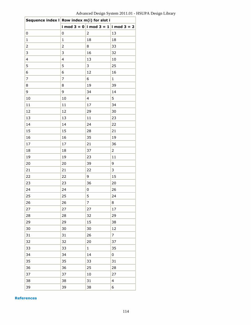
Advanced Design System 2011.01 - HSUPA Design Library
114
Sequence index l Row index m(i) for slot i
i mod 3 = 0 i mod 3 = 1 i mod 3 = 2
0 0 2 13
1 1 18 18
2 2 8 33
3 3 16 32
4 4 13 10
5 5 3 25
6 6 12 16
7 7 6 1
8 8 19 39
9 9 34 14
10 10 4 5
11 11 17 34
12 12 29 30
13 13 11 23
14 14 24 22
15 15 28 21
16 16 35 19
17 17 21 36
18 18 37 2
19 19 23 11
20 20 39 9
21 21 22 3
22 22 9 15
23 23 36 20
24 24 0 26
25 25 5 24
26 26 7 8
27 27 27 17
28 28 32 29
29 29 15 38
30 30 30 12
31 31 26 7
32 32 20 37
33 33 1 35
34 34 14 0
35 35 33 31
36 36 25 28
37 37 10 27
38 38 31 4
39 39 38 6
References
Advanced Design System 2011.01 - HSUPA Design Library
115
3GPP Technical Specification TS 25.211, "Physical channels and mapping of transport1.channels onto physical channels (FDD)," Version 7.6.0, May 2008.3GPP Technical Specification TS 25.212, "Multiplexing and channel coding (FDD),"2.Version 7.9.0, Sep. 2008.3GPP Technical Specification TS 25.213, "Spreading and modulation (FDD)," Version3.7.6.0, Sep. 2008.

Advanced Design System 2011.01 - HSUPA Design Library
116
HSUPA_Spread
Description: HSUPA spreaderLibrary: HSUPA, Multiplexers & Coders
Parameters
Name Description Default Type
DPDCH_Configured Setting to YES if DPDCH is configured, otherwise NO: NO, YES NO enum
HSDPCCH_Configured Setting to YES if HS-DPCCH is configured, otherwise NO: NO, YES NO enum
Pin Inputs
Pin Name Description Signal Type
1 DPDCH DPDCH int
2 DPCCH DPCCH int
3 EDPCCH E-DPCCH int
4 HSDPCCH HS-DPCCH int
5 SltF_D slot format of DPDCH int
6 NumED number of E-DPDCH int
7 SltF_ED slot format of E-DPDCH, only valid when number of E-DPDCH is 1 or2.
int
8 GainD gain factor of DPDCH over DPCCH, in dB real
9 GainED gain factor of E-DPDCH over DPCCH, in dB real
10 GainEC gain factor of E-DPCCH over DPCCH, in dB real
11 GainHS gain factor of HS-DPCCH over DPCCH, in dB real
12 EDPDCH E-DPDCH multiple real
Pin Outputs
Pin Name Description Signal Type
13 Output output complex
Notes/Equations
This model is used to spread, power-scale, and multiplex uplink signals according to1.[3].

Advanced Design System 2011.01 - HSUPA Design Library
117
Each firing, 2560 Output tokens are generated when 2560 DPDCH tokens, 10 DPCCH2.tokens, 10 EDPCCH tokens, 10 HSDPCCH tokens, 1 SltF_D token, 1 NumED token, 1SltF_ED token, 1 GainD token, 1 GainED token, 1 GainEC token, 1 GainHS token and2560 EDPDCH tokens are consumed.The input of DPDCH and E-DPDCH must be repeated to chip rate before it is fed into3.this model. The spreading code will be multiplied directly with input signal.Table 0 of Maximum number of simultaneous uplink dedicated channels in [3] is4.copied here in Maximum number of simultaneous uplink dedicated channelsas shown below. Since whenever there are enhanced uplink channels, the maximumnumber of DPDCH is less than 2, the input of DPDCH is not designed as a multipleport.Configuration # DPDCH HS-DPCCH E-DPDCH E-DPCCH
1 6 1 - -
2 1 1 2 1
3 - 1 4 1
SltF_D is the slot format for DPDCH, which can be found in 5.2.1.1[1]. This input is5.used to determine SF of DPDCH. It determines the spreading code at the same timebecause according to [3], when only one DPDCH is to be transmitted, DPDCH1 shallbe spread by code cd,1 = C ch,SF,k where SF is the spreading factor of DPDCH1 and k
= SF / 4.Num_ED and SltF_ED are the number and slot format of E-DPDCH, which can be6.found in 5.2.1.3[1]. SltF_ED is used to determine SF of each E-DPDCH. WhenNum_ED is 4, SltF_ED is ignored and the spreading code of E-DPDCH1 and E-DPDCH2 is C ch,2,1. The spreading code of E-DPDCH3 and E-DPDCH4 is always C
ch,4,1.
If parameter DPDCH_Configured is set to YES, N max-dpdch is 1, while if it is set to7.
NO, N max-dpdch is 0. Table 1E of Channelisation code for E-DPDCH in [3] is copied
into Channelisation code for E-DPDCH as shown below:N max-dpdch E-DPDCH k Channelisation code C ed,k
0 E-DPDCH 1 C ch,SF,SF/4 if SF ≥ 4C ch,2,1 if SF = 2
E-DPDCH 2 C ch,4,1 if SF = 4C ch,2,1 if SF = 2
E-DPDCH 3 E-DPDCH 4 C ch,4,1
1 E-DPDCH 1 C ch,SF,SF/2
E-DPDCH 2 C ch,4,2 if SF = 4C ch,2,1 if SF = 2
Related information in Table 1D of Channelisation code of HS-DPCCH in [3] is copied8.into Channelisation code of HS-DPCCH as shown below:Nmax-dpdch Channelisation code chs
0 C ch,256,33
1 C ch,256,64
The DPCCH is defined as power reference of other uplink channels in this model. For9.example, GainED is the gain of power level of E-DPDCH over DPCCH in dB units. Thefactor multiplied to the data of DPCCH is 1, while the factor multiplied to the data ofeach E-DPDCH is 20*log(GainED).GainED is gain for each E-DPDCH. If there are four E-DPDCHs, GainED is the gain for10.E-DPDCH 3 and E-DPDCH 4. The gain for E-DPDCH 1 and E-DPDCH 2 is GainED+3dB.
For more information, please refer to 5.1.2.5B.2.3 in [4].After spreading and power scaling, the uplink channels will be mapped to IQ11.

Advanced Design System 2011.01 - HSUPA Design Library
118
branches. DPCCH is always transmitted in Q branch; E-DPCCH is always transmittedin I branch; HS-DPCCH is always transmitted in Q branch; DPDCH 1 is always
transmitted in I branch; Table 1C of the IQ branch mapping for E-DPDCH in [3] iscopied into IQ branch mapping for E-DPDCH as shown below:N max-dpdch HS-DSCH configured E-DPDCH k iq ed,k
0 No/Yes E-DPDCH 1 1
E-DPDCH 2 j
E-DPDCH 3 1
E-DPDCH 4 j
1 No E-DPDCH 1 j
E-DPDCH 2 1
1 Yes E-DPDCH 1 1
E-DPDCH 2 j
The uplink signal is normalized to ensure its RMS value is 1.12.
References
3GPP Technical Specification TS 25.211, "Physical channels and mapping of transport1.channels onto physical channels (FDD)," Version 7.6.0, May 2008.3GPP Technical Specification TS 25.212, "Multiplexing and channel coding (FDD),"2.Version 7.9.0, Sep. 2008.3GPP Technical Specification TS 25.213, "Spreading and modulation (FDD)," Version3.7.6.0, Sep. 2008.3GPP Technical Specification TS 25.214, "Physical layer procedures (FDD)," Version4.7.9.0, May 2008.

Advanced Design System 2011.01 - HSUPA Design Library
119
HSUPA_UL_Rake
Description: HSUPA uplink receiverLibrary: HSUPA, Receivers
Parameters

Advanced Design System 2011.01 - HSUPA Design Library
120
Name Description Default Type Range
SlotFormat slot format 0 int †
ScrambleCode index of scramble code 0 int [0,512] for downlink;<br>[0,16777215] for uplink
Scramble scramble code type:LONG, SHORT
LONG enum
SampleRate sample rate 8 int [1,256]
MaxDelaySample maximum delayboundary, in terms ofsamples
0 int [0,2559] for RAKEreceiver;<br>[0,102400] in othermodels
ChannelType select the channel type tobe processed:CH_GAUSSIAN,CH_FADING
CH_GAUSSIAN enum
ChannelInfo fading channelinformation source:Known, Estimated
Known enum
ChannelInfoOffset offset between spreadcode and channelinformation in terms ofsample
0 int [0,MaxDelaySample]
PathSearch path search frequency:EverySlot, Once
Once enum
SearchMethod path search method:Coherent, NonCoherent,Combined
Coherent enum
SearchSlotsNum number of slots for pathsearch
1 int [1,12]
PathNum number of Rake fingers 1 int [1,6]
PathDelaySample delay for each finger, interms of samples
0 intarray
[0,MaxDelaySample];<br>array sizeshall be equal to PathNum
EstSlotsNum Number of slots forchannel estimation
1 int [1,3]
UseMovingEstWindow If use moving window inchannel estimation: NO,YES
NO enum
UsePastSearch If use past samples forpath searching: NO, YES
NO enum
TTI Transmission timeinterval: TTI 2ms, TTI10ms
TTI 2ms enum
DPDCH_Configured Setting to YES if DPDCHis configured, otherwiseNO: NO, YES
NO enum
HSDPCCH_Configured Setting to YES if HS-DPCCH is configured,otherwise NO: NO, YES
NO enum
† [0:5] for uplink DPCCH;<br>[0:16] for downlink DPCH;<br>[0:17] for downlinkSCCPCH;<br>[0:5] for uplink PCPCH (Ver 03_00);<br>[0:2] for uplink PCPCH (Ver12_00);<br>[0:1] for uplink PCPCH (Ver 03_02).
Pin Inputs

Advanced Design System 2011.01 - HSUPA Design Library
121
Pin Name Description Signal Type
1 inChip input data stream complex
2 NumED number of E-DPDCH int
3 SltF_ED slot format of E-DPDCH int
4 inChM input known channel information multiple complex
Pin Outputs
Pin Name Description Signal Type
5 EDPCCH E-DPCCH real
6 PwrN power of noise estimated from DPCCH real
7 SlotIndex slot number int
8 Delay path delay int
9 EDPDCH E-DPDCH multiple real
10 outChM output estimated channel information multiple complex
Notes/Equations
This model is used to demodulate and despread HSUPA uplink signals at a 3.84MHz1.chip rate. Such signals can be corrupted by multipath fading channel and additiveGaussian noise.Each firing, 2560 EDPDCH tokens, 10 EDPCCH tokens, 1 DPCCH tokens, 1 SlotIndex2.token, 1 Delay token, and 2560 outChM tokens are produced when2560*SamplesPerChip inChip and inChM tokens, 1 Num_ED token, and 1 SltF_EDtoken are consumed.For information about the parameters related to the configuration of uplink channels,3.see HSUPA_Spread (hsupa).To despread and demodulate a CDMA signal, the channel information and path delay4.information must be determined. Errors in channel estimation and path searchdeteriorate the receiver performance.The signal processing flow inside the model is:5.
Input data until slots specified by SearchSlotsNum are receivedSlot index identificationIQ offset correction to eliminate any DC component.Multipath searchChannel estimation for each pathDecode and despread of individual pathSNR estimation for individual pathMultipath combinationOutput decoded data and SlotIndex to align at the frame boundaryOutput Delay and channel information (slots delayed are specified bySearchSlotsNum)
This model can be configured to work under ideal conditions; in other words, the real6.time channel information can be input from input pin and the path delay informationcan be set by the PathDelaySample parameter.The ChannelInfo parameter selects the channel information source from input or7.estimated inside the model. The delay for each path is expressed in terms of samplesas individual elements in the array.f path delay is specified, the SearchSlotsNum is 1.8.If the first element in PathDelaySample is 0, the path search is performed inside thereceiver model. Otherwise, the numbers specified by PathDelaySample are taken asthe delays for each path.The path search is performed by correlating the received signals with the spreading9.code specified in a window whose size is set by MaxDelaySample. The correlations atdifferent offsets are ranked and the top ones are assumed to be the offsets where thepaths could occur.If SearchMethod = Coherent, the correlation will be performed at the pilot bits only.10.
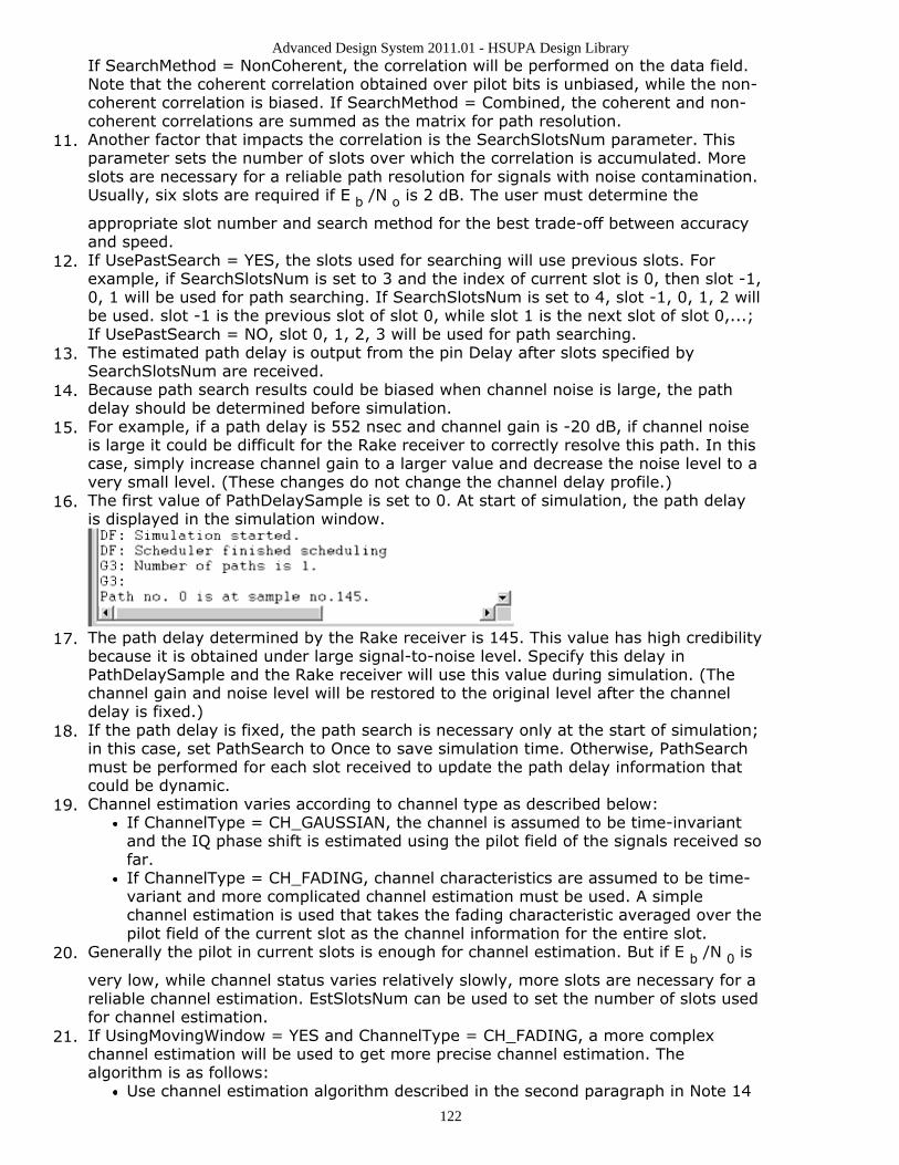
Advanced Design System 2011.01 - HSUPA Design Library
122
If SearchMethod = NonCoherent, the correlation will be performed on the data field.Note that the coherent correlation obtained over pilot bits is unbiased, while the non-coherent correlation is biased. If SearchMethod = Combined, the coherent and non-coherent correlations are summed as the matrix for path resolution.Another factor that impacts the correlation is the SearchSlotsNum parameter. This11.parameter sets the number of slots over which the correlation is accumulated. Moreslots are necessary for a reliable path resolution for signals with noise contamination.Usually, six slots are required if E b /N o is 2 dB. The user must determine the
appropriate slot number and search method for the best trade-off between accuracyand speed.If UsePastSearch = YES, the slots used for searching will use previous slots. For12.example, if SearchSlotsNum is set to 3 and the index of current slot is 0, then slot -1,0, 1 will be used for path searching. If SearchSlotsNum is set to 4, slot -1, 0, 1, 2 willbe used. slot -1 is the previous slot of slot 0, while slot 1 is the next slot of slot 0,...;If UsePastSearch = NO, slot 0, 1, 2, 3 will be used for path searching.The estimated path delay is output from the pin Delay after slots specified by13.SearchSlotsNum are received.Because path search results could be biased when channel noise is large, the path14.delay should be determined before simulation.For example, if a path delay is 552 nsec and channel gain is -20 dB, if channel noise15.is large it could be difficult for the Rake receiver to correctly resolve this path. In thiscase, simply increase channel gain to a larger value and decrease the noise level to avery small level. (These changes do not change the channel delay profile.)The first value of PathDelaySample is set to 0. At start of simulation, the path delay16.is displayed in the simulation window.
The path delay determined by the Rake receiver is 145. This value has high credibility17.because it is obtained under large signal-to-noise level. Specify this delay inPathDelaySample and the Rake receiver will use this value during simulation. (Thechannel gain and noise level will be restored to the original level after the channeldelay is fixed.)If the path delay is fixed, the path search is necessary only at the start of simulation;18.in this case, set PathSearch to Once to save simulation time. Otherwise, PathSearchmust be performed for each slot received to update the path delay information thatcould be dynamic.Channel estimation varies according to channel type as described below:19.
If ChannelType = CH_GAUSSIAN, the channel is assumed to be time-invariantand the IQ phase shift is estimated using the pilot field of the signals received sofar.If ChannelType = CH_FADING, channel characteristics are assumed to be time-variant and more complicated channel estimation must be used. A simplechannel estimation is used that takes the fading characteristic averaged over thepilot field of the current slot as the channel information for the entire slot.
Generally the pilot in current slots is enough for channel estimation. But if E b /N 0 is20.
very low, while channel status varies relatively slowly, more slots are necessary for areliable channel estimation. EstSlotsNum can be used to set the number of slots usedfor channel estimation.If UsingMovingWindow = YES and ChannelType = CH_FADING, a more complex21.channel estimation will be used to get more precise channel estimation. Thealgorithm is as follows:
Use channel estimation algorithm described in the second paragraph in Note 14

Advanced Design System 2011.01 - HSUPA Design Library
123
to get initial channel information.Despread and decode data transmitted in the DPCCH using the channelinformation.Use the decode data as know information so that all the symbols in DPCCH canbe can be think as pilot and used in channel estimation.Set estimation window to be 21 DPCCH symbols centered at each DPCCHsymbol of current slot.Moving-average 21 fading characteristics in estimation window to get 10channel coefficients and each of them used as channel information of correspondsymbol interval.
Channel information that is estimated or known from input pins is output from the22.pin outChM for reference. Each firing, 2560 tokens are produced as the channelinformation for the chips in the slot indicated by SlotIndex.All paths are combined assuming that all the paths are useful in improving the23.decoding reliability. Some paths with low SNR are actually harmful to the final SNRimprovement. The user must determine the PathNum setting for better decodingperformance in multipath conditions.Each firing, input tokens is 2560 24.SampleRate. There is a delay in terms of slots associated with the decodedinformation. The outputs are aligned at the TTI boundary; for example, if the firstreceived slot index is 0 and TTI is 2ms, the decoded bit stream will be output afterthree slots.If the HSUPA signal is S(t), this signal may be delayed t1 by some filters (such as the25.Tx RC filters). So, the delayed signal is S(t-t1) and the signal from 0 to t1 is zero andthe real 3GPP signal transmission starts from t1. When the delayed signals passthrough a fading channel, the fading factor is applied to the overall signals startingfrom time 0. The offset t1 must be known if the receiver of the channel information isinput from outside; this offset is expressed in terms of samples. The followingdescription provides more details.
Denote the signal source output as:
S 1, S 2, S 3,..., S i,... These signals are fed to the transmitter module,
and the transmitter module introduces delay (for example, the squareroot raised-cosine filter introduces the delay that is related with thefilter length); denote this delay as N .
The output signals from transmitter module are:
0, 0, 0,..., 0, S 1, S 2, S 3,..., S i,... The number of 0s is N. These
signals are fed to the fading channel model.The fading channel module generates the fading factors, that can be denotedas:
f 1, f 2, f 3,..., f i,... These factors will be applied to the input signals.
They can also be input to the Rake receiver as phase reference.The resultant faded signals are:
f 1× 0, f 2× 0, f 3× 0, ... , f N× 0, ... , f N+1× S 1, f N+2× S 2 Note that
the faded signal must pass the receiver module that introducesadditional delay; this does not impact the channel information offsetsetting.
The channel information being input to the Rake receiver is:
f 1, f 2, f 3, ... , f i, ... The Rake receiver must know the offset between
the faded signal and the known channel information. In this case, the

Advanced Design System 2011.01 - HSUPA Design Library
124
offset is N, and the Rake receiver will take the Nth input from thechannel information input and correlate it with the signal start point.The signal start point is determined by the synchronization moduleimplemented inside the Rake receiver.
References
3GPP Technical Specification TS 25.211, "Physical channels and mapping of transport1.channels onto physical channels (FDD)," Version 7.10.0, Dec. 2008.3GPP Technical Specification TS 25.212, "Multiplexing and channel coding (FDD),"2.Version 7.9.0, Sept. 2008.3GPP Technical Specification TS 25.213, "Spreading and modulation (FDD)," Version3.7.6.0, Sept. 2008.3GPP Technical Specification TS 25.104, "UTRA (BS) FDD: Radio transmission and4.Reception," Version 7.10.0, Mar. 2008.3GPP Technical Specification TS 25.141, "Base station conformance test," Version5.7.11.0, Mar. 2008.

Advanced Design System 2011.01 - HSUPA Design Library
125
HSUPA_UL_Source
Description: HSUPA uplink signal sourceLibrary: HSUPA, Signal Sources
Parameters

Advanced Design System 2011.01 - HSUPA Design Library
126
Name Description Default Symbol Unit Type Range
EDCH_Category FDD E-DCH physical layercategories: Category 1,Category 2, Category 3,Category 4, Category 5,Category 6, Category 7
Category 6 enum
TransBlockSize Transport block size 2706 L int [1,max transportblock size]†
TTI Transmission time interval:TTI 2ms, TTI 10ms
TTI 2ms enum
PuncLimit Puncturing limit for uplink 0.468 real [PLmax , 1]‡
RV_Mode Redundancy version mode:Calculated using RSN, Onlyindex 0
Calculatedusing RSN
enum
MaxRSN Maximum retransmissionsequence number
3 int [0,3]
HARQ_PrcssMode Way to setting number ofHARQ: Depending on TTI,User defined
Dependingon TTI
enum
NumHARQ Number of HARQ processes 4 int [4,8]
DataPattern Source data pattern:Random, PN9, PN15, RepeatBits
Random enum
RepeatBitValue Repeating data value 0x0001 int [0, 65535]
RepeatBitPeriod Repeating data period 2 int [1, 16]
DPDCH_Configured Setting to YES if DPDCH isconfigured, otherwise NO:NO, YES
NO enum
HSDPCCH_Configured Setting to YES if HS-DPCCHis configured, otherwise NO:NO, YES
NO enum
GainD channel gain of DPDCH overDPCCH
-300 dB real [-∞, +∞)
GainED channel gain of E-DPDCHover DPCCH
12.04 dB realarray
[-∞, +∞)
GainEC channel gain of E-DPCCHover DPCCH
6.02 dB realarray
[-∞, +∞)
GainHS channel gain of HS-DPCCHover DPCCH
-300 dB realarray
[-∞, +∞)
SlotF_DPDCH slot format index of DPDCH 2 int [0,6]
Scramble scramble code type: LONG,SHORT
LONG enum
ScrambleCode Index of scramble code 0 int [0,512] fordownlink;<br>[0,16777215] for uplink
Pin Inputs
Pin Name Description Signal Type
1 ARQ automatic repeat request int
Pin Outputs

Advanced Design System 2011.01 - HSUPA Design Library
127
Pin Name Description Signal Type
2 Output output complex
3 RSN retransmission sequencenumber
int
4 BitED bits of E-DPDCH int
5 BitEC bits of E-DPCCH int
Notes/Equations
This subnetwork is used to implement baseband uplink source for HSUPA.1.The schematic is shown below:2.
For more information about E-DCH parameters, see HSUPA_RateMatch (hsupa).3.For more information about HARQ function, see HSUPA_Bits (hsupa) and4.HSUPA_RateMatch (hsupa).For more information, please refer to the documentation for models used in this5.subnetwork.
References
3GPP Technical Specification TS 25.211, "Physical channels and mapping of transport1.channels onto physical channels (FDD)," Version 7.6.0, May 2008.3GPP Technical Specification TS 25.212, "Multiplexing and channel coding (FDD),"2.Version 7.9.0, Sep. 2008.3GPP Technical Specification TS 25.213, "Spreading and modulation (FDD)," Version3.7.6.0, Sep. 2008.

Advanced Design System 2011.01 - HSUPA Design Library
128
HSUPA_UL_SourceRF
Description: HSUPA RF uplink signal sourceLibrary: HSUPA, Signal Sources
Parameters
Name Description Default Symbol Unit Type Range
ROut Source resistance DefaultROut Ohm real (0,∞)
RTemp Temperature DefaultRTemp Celsius real [-273.15,∞)
TStep Expression showinghow TStep is relatedto the other sourceparameters
1/3.84MHz/SamplesPerChip
string
FCarrier Carrier frequency 1950MHz Hz real (0,∞)
Power Power dbmtow(24.0) W real [0,∞)
MirrorSpectrum Mirror spectrumabout carrier?: NO,YES
NO enum
GainImbalance Gain imbalance, Qvs I
0.0 dB real (-∞,∞)
PhaseImbalance Phase imbalance, Qvs I
0.0 deg real (-∞,∞)
I_OriginOffset I origin offset(percent)
0.0 real (-∞,∞)
Q_OriginOffset Q origin offset(percent)
0.0 real (-∞,∞)
IQ_Rotation IQ rotation 0.0 deg real (-∞,∞)
SamplesPerChip Samples per chip 8 S int [2,32]
RRC_FilterLength RRC filter length(chips)
16 int [2,128]
ExcessBW Excess bandwidth ofraised cosine filters
0.22 real (0.0,1.0)
RV_Mode Redundancy versionmode: Calculatedusing RSN, Onlyindex 0
Calculated using RSN enum
MaxRSN Maximumretransmissionsequence number
3 int [0,3]

Advanced Design System 2011.01 - HSUPA Design Library
129
HARQ_PrcssMode Way to settingnumber of HARQ:Depending on TTI,User defined
Depending on TTI enum
NumHARQ Number of HARQprocesses
4 int [2,8]
ScrambleCode Index of scramblecode
0 int [0,512] fordownlink;<br>[0,16777215] foruplink
Scramble scramble code type:LONG, SHORT
LONG enum
DataPattern Source data pattern:Random, PN9,PN15, Repeat Bits
Random enum
RepeatBitValue Repeating datavalue
0x0001 int [0, 65535]
RepeatBitPeriod Repeating dataperiod
2 int [1, 16]
EDCH_Category FDD E-DCH physicallayer categories:Category 1,Category 2,Category 3,Category 4,Category 5,Category 6,Category 7
Category 6 enum
TransBlockSize Transport block size 2706 L int [1,max transportblock size]†
TTI Transmission timeinterval: TTI 2ms,TTI 10ms
TTI 2ms enum
PuncLimit Puncturing limit foruplink
0.468 real [PLmax , 1]‡
DPDCH_Configured Setting to YES ifDPDCH isconfigured,otherwise NO: NO,YES
NO enum
HSDPCCH_Configured Setting to YES if HS-DPCCH isconfigured,otherwise NO: NO,YES
NO enum
GainD channel gain ofDPDCH over DPCCH
-300 dB real [-∞, +∞)
GainED channel gain of E-DPDCH over DPCCH
12.04 dB realarray
[-∞, +∞)
GainEC channel gain of E-DPCCH over DPCCH
6.02 dB realarray
[-∞, +∞)
GainHS channel gain of HS-DPCCH over DPCCH
-300 dB realarray
[-∞, +∞)
SlotF_DPDCH slot format index ofDPDCH
2 int [0,6]
Pin Inputs
Pin Name Description Signal Type
1 ARQ automatic repeat request int
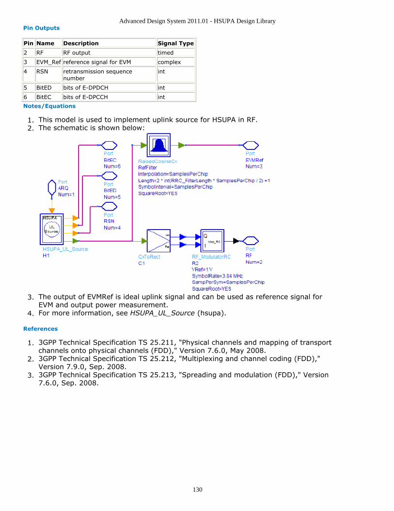
Advanced Design System 2011.01 - HSUPA Design Library
130
Pin Outputs
Pin Name Description Signal Type
2 RF RF output timed
3 EVM_Ref reference signal for EVM complex
4 RSN retransmission sequencenumber
int
5 BitED bits of E-DPDCH int
6 BitEC bits of E-DPCCH int
Notes/Equations
This model is used to implement uplink source for HSUPA in RF.1.The schematic is shown below:2.
The output of EVMRef is ideal uplink signal and can be used as reference signal for3.EVM and output power measurement.For more information, see HSUPA_UL_Source (hsupa).4.
References
3GPP Technical Specification TS 25.211, "Physical channels and mapping of transport1.channels onto physical channels (FDD)," Version 7.6.0, May 2008.3GPP Technical Specification TS 25.212, "Multiplexing and channel coding (FDD),"2.Version 7.9.0, Sep. 2008.3GPP Technical Specification TS 25.213, "Spreading and modulation (FDD)," Version3.7.6.0, Sep. 2008.

Advanced Design System 2011.01 - HSUPA Design Library
131
HSUPA User Equipment Receiver DesignExamplesThe HSUPA_UE_Rx_wrk workspace shows user equipment receiver measurementperformances, including E-AGCH demodulation performance, E-HICH detectionperformance, and E-RGCH detection performance.
Designs for these measurements are described in the following sections; they include:
E-AGCH demodulation performance:UE_Rx_EAGCH_DemodulationUE_Rx_EAGCH_DemodulationFading
E-HICH detection performance:UE_Rx_EHICH_DetectionUE_Rx_EHICH_DetectionFading
E-RGCH detection performance:UE_Rx_ERGCH_DetectionUE_Rx_ERGCH_DetectionFading
Designs under this workspace consist of:
Downlink RF band signal source: HSUPA_DL_SourceRF is used to provide an RFHSUPA downlink signal source.Fading channel: HSPA_Channel is used to provide various multi-path fadingpropagation conditions.AWGN noise: AddNDensity is used to provide AWGN in order to calibrate the E c /I or
at certain levels, which are required by various performance measurements.User Equipment RF receiver: HSUPA_DL_ReceiverRF is used to provide a receiver ofRF HSUPA downlink signals.

Advanced Design System 2011.01 - HSUPA Design Library
132
E-AGCH Demodulation Performance MeasurementsDesign: UE_Rx_EAGCH_DemodulationFading, UE_Rx_EAGCH_Demodulation
Features:
User equipment E-AGCH demodulation performance measurementsIntegrated RF modelsMulti-path fading propagation conditions
Description:
UE_Rx_EAGCH_DemodulationFading measures user equipment receiver E-AGCHdemodulation performance according to section 10.4.1 in TS 25.101.UE_Rx_EAGCH_Demodulation measures user equipment receiver E-AGCHdemodulation performance over AWGN condition to provide the baseline reference.
The schematics for fading and AWGN conditions are shown inUE_Rx_EAGCH_DemodulationFading Schematic and UE_Rx_EAGCH_DemodulationSchematic respectively.
UE_Rx_EAGCH_DemodulationFading Schematic
UE_Rx_EAGCH_Demodulation Schematic
Simulation Results:Simulation results are shown in User Equipment E-AGCH Demodulation PerformanceResults (Fading) and User Equipment E-AGCH Demodulation Performance Results (AWGN).

Advanced Design System 2011.01 - HSUPA Design Library
133
User Equipment E-AGCH Demodulation Performance Results (Fading)
User Equipment E-AGCH Demodulation Performance Results (AWGN)
Benchmark:Simulation time is about 30 hours (fading) and 3 hours (AWGN) for 2000 10µs TTI, on aP4/2.6GHz 512M PC running ADS 2005A on Microsoft Windows 2000.

Advanced Design System 2011.01 - HSUPA Design Library
134
E-HICH Detection Performance MeasurementsDesign: UE_Rx_EHICH_DetectionFading, UE_Rx_EHICH_Detection
Features:
User equipment E-HICH demodulation performance measurementsIntegrated RF modelsMulti-path fading propagation conditions
Description:
UE_Rx_EHICH_DetectionFading measures user equipment receiver E-HICH detectionperformance according to section 10.2.1 in TS 25.101.UE_Rx_EHICH_Detection measures user equipment receiver E-HICH detectionperformance over AWGN condition to provide the baseline reference.
The schematics of fading and AWGN conditions are shown inUE_Rx_EHICH_DetectionFading Schematic and UE_Rx_EHICH_Detection Schematicrespectively.
UE_Rx_EHICH_DetectionFading Schematic
UE_Rx_EHICH_Detection Schematic
Simulation Results:Simulation results are shown in User Equipment E-HICH Detection Performance Results(Fading) and User Equipment E-HICH Detection Performance Results (AWGN).
User Equipment E-HICH Detection Performance Results (Fading)

Advanced Design System 2011.01 - HSUPA Design Library
135
User Equipment E-HICH Detection Performance Results (AWGN)
Benchmark:Simulation time is about 9.7 hours (fading, VA30) and 3 hours (AWGN) for 11000 2µs TTI,on a P4/2.6GHz 512MB PC running ADS 2005A on Microsoft Windows 2000.

Advanced Design System 2011.01 - HSUPA Design Library
136
E-RGCH Detection Performance MeasurementsDesign: UE_Rx_ERGCH_Detection, UE_Rx_ERGCH_DetectionFading
Features:
User equipment E-RGCH demodulation performance measurementsIntegrated RF modelsMulti-path fading propagation conditions
Description:
UE_Rx_ERGCH_DetectionFading measures user equipment receiver E-RGCHdetection performance according to section 10.3.1 in TS 25.101.UE_Rx_ERGCH_Detection measures user equipment receiver E-RGCH detectionperformance over AWGN condition to provide the baseline reference.
The schematics for fading and AWGN conditions are shown inUE_Rx_ERGCH_DetectionFading Schematic and UE_Rx_ERGCH_Detection Schematic.
UE_Rx_ERGCH_DetectionFading Schematic
UE_Rx_ERGCH_Detection Schematic
Simulation Results:Simulation results are shown in User Equipment E-RGCH Detection Performance Results(Fading) and User Equipment E-RGCH Detection Performance Results (AWGN).
User Equipment E-RGCH Detection Performance Results (Fading)

Advanced Design System 2011.01 - HSUPA Design Library
137
User Equipment E-RGCH Detection Performance Results (AWGN)
Benchmark:Simulation time is about 10 hours (fading) and 1.5 hours (AWGN) for 6000 2µs TTI, on aP4/2.6GHz 512MB PC running ADS 2005A on Microsoft Windows 2000.
References
3GPP Technical Specification TS 25.101, "UE Radio transmission and Reception1.(FDD)," Version 7.13.0, Sept. 2008.

Advanced Design System 2011.01 - HSUPA Design Library
138
HSUPA User Equipment TransmitterDesign ExamplesThe HSUPA_UE_Tx_wrk workspace shows user equipment transmitter measurementcharacteristics, including adjacent channel leakage power ratio (ACLR), complementarycumulative distribution function (CCDF), error vector magnitude (EVM), maximum power,and spectrum emission mask. Designs for these measurements are described in thefollowing sections; they include:
Adjacent channel leakage power ratio measurements: UE_Tx_ACLRCCDF and peak-to-mean information measurements: UE_Tx_CCDFError vector magnitude measurements: UE_Tx_EVMMaximum power measurements: UE_Tx_Max_PowerSpectrum emission mask measurements: UE_Tx_SpecEmissions

Advanced Design System 2011.01 - HSUPA Design Library
139
Adjacent Channel Leakage Power RatioMeasurementsDesign: UE_Tx_ACLR
HSUPA_UL_SourceRF is used to provide an RF HSUPA uplink signal source for the designs under thisworkspace.
Features:
HSUPA uplink RF signal sourcesignal source including DPCCH, DPDCH, E-DPCCH, E-DPDCH, and HSDPCCHpower in an adjacent channel measured using FFT
Description:
This design measures user equipment transmitter adjacent channel leakage powerratio (ACLR) characteristics according to section 6.6.2.2 in TS 25.101.ACLR is the ratio of the transmitted power to the power measured in an adjacentchannel. Both the transmitted power and the adjacent channel power are measuredwith a filter that has a root-raised cosine (RRC) filter response with a rolloff of 0.22and a bandwidth equal to the chip rate. 3GPPFDD_RF_ACLR is used to measureoutput power.Frequency domain power in 4 adjacent channels is measured: 2 above and 2 belowthe center frequency of the measured signal.3GPPFDD_RF_ACLR is used to measure output powerThe schematic is shown below:
Simulation Results:Simulation results are shown below:
User Equipment ACLR Measurement Results - Table:

Advanced Design System 2011.01 - HSUPA Design Library
140
And User Equipment ACLR Measurement Results - Figure:
Benchmark:Simulation time is about 12 seconds on a Pentium M/1.6GHz 1024MB PC running ADS2005A on Microsoft Windows XP.

Advanced Design System 2011.01 - HSUPA Design Library
141
CCDF and Peak-to-Mean Information MeasurementsDesign: UE_Tx_CCDF
Features:
HSUPA uplink RF signal sourcesignal source including DPCCH, DPDCH, E-DPCCH, E-DPDCH, and HSDPCCHCCDF and peak-to-mean information measured by the CCDF model
Description:
CCDF measurement is not defined in the 3GPP specification. However, thecomplementary cumulative distribution function (CCDF) and peak-to-meaninformation are very useful for analyzing amplifier performance.The schematic is shown below:
Simulation Results:Simulation results are shown below:
User Equipment CCDF Measurement Results - Table:
And User Equipment CCDF Measurement Results - Figure:

Advanced Design System 2011.01 - HSUPA Design Library
142
Benchmark:Simulation time is about 3 seconds on a Pentium M/1.6GHz 1024MB PC running ADS2005A on Microsoft Windows XP.

Advanced Design System 2011.01 - HSUPA Design Library
143
Error Vector Magnitude MeasurementsDesign: UE_Tx_EVM
Features:
HSUPA uplink RF signal sourcesignal source including DPCCH, DPDCH, E-DPCCH, E-DPDCH, and HSDPCCHerror vector magnitude is measured by the EVM modelphase discontinuity is measured by the EVM modelreference signal is used
Description:
This design measures user equipment transmitter error vector magnitude (EVM) andphase discontinuity characteristics according to section 6.8.2 and 6.8.4 in TS 25.101respectively.EVM is a measure of the difference between the measured waveform and thetheoretical modulated waveform (the error vector). It is the square root of the ratioof the mean error vector power to the mean reference signal power expressed as apercentage.For Release 99 and Release 4, the EVM measurement interval is one timeslot. ForRelease 5 and later releases where tests may include power changes, themeasurement interval is further clarified as being one timeslot except when the meanpower between slots is expected to change whereupon the measurement interval isreduced by 25 ms at each end of the slot.The phase discontinuity is always made in the measurement interval of one timeslotreduced by 25 ms at each end of the slot, then extrapolated in both directions ontothe timeslot boundaries.The schematic is shown in below:
Simulation Results:Simulation results are shown in User Equipment EVM Measurement Results below:

Advanced Design System 2011.01 - HSUPA Design Library
144
Benchmark
Simulation time is about 30 seconds on a Pentium M/1.6GHz 1024MB PC running ADS2005A on Microsoft Windows XP.
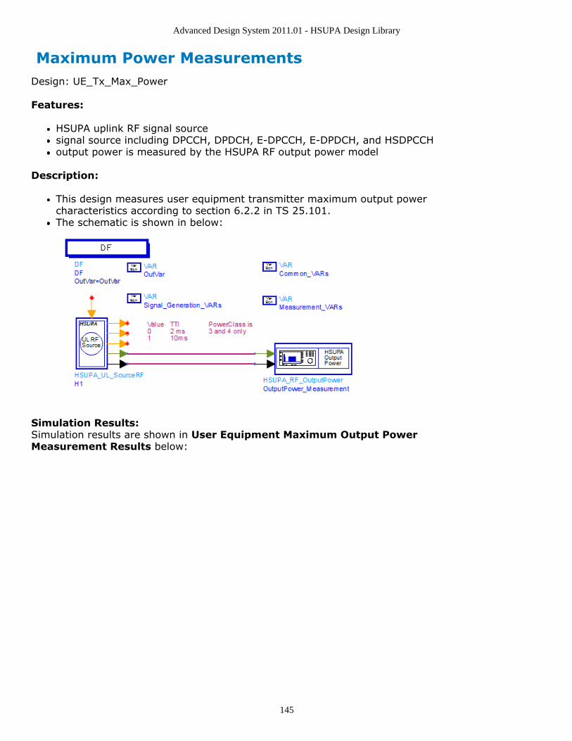
Advanced Design System 2011.01 - HSUPA Design Library
145
Maximum Power MeasurementsDesign: UE_Tx_Max_Power
Features:
HSUPA uplink RF signal sourcesignal source including DPCCH, DPDCH, E-DPCCH, E-DPDCH, and HSDPCCHoutput power is measured by the HSUPA RF output power model
Description:
This design measures user equipment transmitter maximum output powercharacteristics according to section 6.2.2 in TS 25.101.The schematic is shown in below:
Simulation Results:Simulation results are shown in User Equipment Maximum Output PowerMeasurement Results below:

Advanced Design System 2011.01 - HSUPA Design Library
146
Benchmark:Simulation time is about 8 seconds on a Pentium M/1.6GHz 1024MB PC running ADS2005A on Microsoft Windows XP.

Advanced Design System 2011.01 - HSUPA Design Library
147
Spectrum Emission Mask MeasurementsDesign: UE_Tx_SpecEmissions
Features:
HSUPA uplink RF signal sourcesignal source including DPCCH, DPDCH, E-DPCCH, E-DPDCH, and HSDPCCHParamSweep and SweepPlan is used
Description:
This design measures user equipment transmitter out-of-band emissioncharacteristics according to section 6.6.2.1 in TS 25.101.The spectrum emission mask of the UE applies to frequencies, which are between 2.5MHz and 12.5 MHz away from the UE center carrier frequency. The out of channelemission is specified relative to the RRC filtered mean power of the UE carrier.The schematic is shown in below:
Simulation Results:Simulation results are shown in *User Equipment Spectrum Emission Mask MeasurementResults below:

Advanced Design System 2011.01 - HSUPA Design Library
148
Benchmark
Simulation time is about 25 minutes on a Pentium M/1.6GHz 1024MB PC running ADS2005A on Microsoft Windows XP.
References
3GPP Technical Specification TS 25.101, "UE Radio transmission and Reception1.(FDD)," Version 6.11.0, Mar. 2006.