hrsh100/150/200/250-a/w-20-s hfc : gwp eng: 1pc) … · hrsh100/150/200/250-a/w-20-s ......
TRANSCRIPT
HRSH-TFS12
Installation and Maintenance Manual
Thermo-chiller
HRSH100/150/200/250-A/W-20-S
HRSH100/150/200/250-A/W-40-*
HRSH300-A-40-*
Original Instructions 1 Read Before Using
Thank you for purchasing SMC’s Thermo-chiller (hereinafter referred to as the “product”). This “Installation and Maintenance Manual” (hereinafter referred to as this “manual") briefly explains the essential safety instruction procedures to start and stop the product and reset its alarms. Read this manual before using.
2 Safety Instructions
This manual contains essential information for the protection of users and others from possible injury and/or equipment damage.
• Read this manual before using the product, to ensure correct handling, and read the manuals of related apparatus before use.
• Keep this manual in a safe place for future reference.
• These instructions indicate the level of potential hazard by label of “Caution”, “Warning” or “Danger”, followed by important safety information which must be carefully followed.
• To ensure safety of personnel and equipment the safety instructions in this manual and the product catalogue must be observed, along with other relevant safety practices.
Caution
Indicates a hazard with a low level of risk, which if not avoided, could result in minor or moderate injury.
Warning
Indicates a hazard with a medium level of risk, which if not avoided, could result in death or serious injury.
Danger
Indicates a hazard with a high level of risk, which if not avoided, will result in death or serious injury.
Warning
• The compatibility of the product is the responsibility of the person who designs the equipment or decides its specifications.
• Only trained personnel should operate machinery and equipment.
• Assembly, handling or repair of the product should be performed by trained and experienced personnel.
• Do not service machinery/equipment or attempt to remove components until safety is confirmed. 1) Inspection and maintenance of machinery/equipment should only be
performed after confirmation of safe locked-out control positions. 2) Before machinery/equipment is re-started, ensure all safety measures
are implemented.
• The product can be dangerous when handled incorrectly. • Do not use this product outside of the specifications. Contact SMC if it is to
be used in any of the following conditions: 1) Conditions and environments beyond the given specifications, or if the
product is to be used outdoors. 2) Installations in conjunction with atomic energy, railway, air navigation,
vehicles, medical equipment, food and beverage, recreation equipment, emergency stop circuits, press applications, or safety equipment.
3) An application, which has the possibility of having negative effects on people, property, or animals, requiring special safety analysis.
Caution
• Do not use the product in an area of high temperature and humidity which
cannot be exhausted, or where it is exposed to corrosive substances. Cooling failure can result.
• Do not handle the power supply connector and switch with wet hands. Electrical shock can result.
• This product is heavy (over 40kg). When transferring the product with casters pay attention to slopes on the route or by folklift the risk of dropping the product.
• Select piping applicable to the operating pressure range. Otherwise, it can cause fluid leakage or rupture.
3 Specifications
3.1 Product Specifications
HRSH**0 -A*-**-Options (Air-cooled version)
HRSH**0 -W*-**-Options (Water-cooled version)
3 Specifications (continue)
Notes: ∗1 Use 15% ethylene glycol aqueous solution if operating in a place where the
circulating fluid temp. or ambient temperature is lower than 10 oC. (Note: Water-cooled: Please discharge the facility water from the facility water circuit when there is a risk of freezing.)
∗2 Use fluid in condition below as the circulating fluid. Tap water: Standard of The Japan Refregeration And Air Conditioning Industry Association (JRA GL-02-1994) 15% ethylene glycol aqueous solution: diluted by tap water in condition above without any additives such as antiseptics. Deionized water: Conductivity 1µS/cm and higher (electrical resistivity 1MΩ・cm and lower)
∗3 (1) Air-cooled: Operating ambient temp.: 32 oC or Water-cooled: Facility water temp.: 32 oC, (2)Circulating fluid : Tap water, (3)Circulating fluid temp.: 20 oC, (4)Circulating fluid flow rate : Rated flow rate, (5)Power supply: AC200V (-20-∗), AC400V (-40-∗).
∗4 (1) Air-cooled: Operating ambient temp.: 32 oC or Water-cooled: Facility water temp.: 32 oC, (2)Circulating fluid : Tap water, (3) Circulating fluid flow rate : Rated flow rate, (4)Power supply: AC200V (-20-∗), AC400V (-40-∗).
∗5 (1) Air cooled: Operating ambient temp.: 32 oC or Water cooled: Facility water temp .: 32 oC, (2)Circulating fluid : Tap water, (3)Circulating fluid temp.: 20 oC, (4)Heat load : Same as the cooling capacity, (5)Circulating fluid flow rate: Rated flow rate, (6)Power supply : AC200V (-20-∗), AC400V (-40-∗), (7)External piping length: Minimum
∗6 With the pressure control mode of the pump operation mode. When the pressure control mode is not necessary, use the frequency set mode
∗7 Fluid flow rate to maintain the cooling capacity. If the actual flow rate is lower than this, please install a bypass piping.
∗8 The anchor brackets (including M8 bolts) are used for fixation with the skid when this product is packed. The anchor bolts are not attached
3.2 General Description and Intended Use
This product used a built-in pump to circulate a liquid such as water, adjusted to a constant temperature by the refrigeration circuit. This circulating liquid cools parts of customer’s machine that generate heat. 3.3 Production Serial Number Code
The production serial number code printed on the label indicates the month and year of production as per the following table:
Year 2015 2016 2017 …. 2021 2022 2023 ….
Month T U V …. Z A B …. Jan o To Uo Vo …. Zo Ao Bo …. Feb P TP UP VP …. ZP AP BP …. Mar Q TQ UQ VQ …. ZQ AQ BQ …. Apr R TR UR VR …. ZR AR BR …. May S TS US VS …. ZS AS BS …. Jun T TT UT VT …. ZT AT BT …. Jul U TU UU VU …. ZU AU BU …. Aug V TV UV VV …. ZV AV BV …. Sep W TW UW VW …. ZW AW BW …. Oct X TX UX VX …. ZX AX BX …. Nov y Ty Uy Vy …. Zy Ay By …. Dec Z TZ UZ VZ …. ZZ AZ BZ ….
4 How to Order
HRSHCooling capacity
Cooling method
Piping thread type Power supply
- - -Option
A Air-cooled refrigeration
NoneNill
Caster-foot adjuster installed
A
Nil Rc
F G (Rc-G thread adapter set is included)
N NPT (Rc-NPT thread adapter set is included)
100 10kW
250
200 20kW
25kW
20AC200V (50Hz) 3phase
AC200~230V (60Hz) 3phase
W Water-cooled refrigeration
150 15kW
1
2
5
3 4
40AC380-415V 50/60Hz 3phase
CE Marked
*1: Manual fluid fill port that is different from the automatic fluid-fill function. This enables that circulating fluid can be filled manually without removing the side panel. (In case of without K option, circulating fluid can be filled manually removing the side panel.)*2: Power supply 20 type only.
300*3 30kW
Fluid fill portK*1
CE/UL compliantS*2
*3: Air cooled only.
5 Name of Parts and Accessories
5.1 Accessories
• Check the enclosed accessories with the delivered thermo-chiller.
1 Alarm cord list label 2
(JPN: 1pc, ENG: 1pc)
2 Operation manual
2 (JPN: 1pc, ENG: 1pc)
3 Y strainer (40 meshes) 25A
1pc
4 Barrel nipple 25A
1pc
5
HRSH ***-AF-** G thread adapter set (HRS-EP014) HRSH ***-AN-** NPT thread adapter set (HRS- EP013)
1 set
HRSH ***-WF-** G thread adapter set (HRS-EP016) HRSH ***-WN-** NPT thread adapter set (HRS- EP015)
- Anchor brackets 2 pcs.
--- (M8 bolts) 6 pcs.
*These accessories are not explained in this manual. For details, refer to the Operation Manual attached.
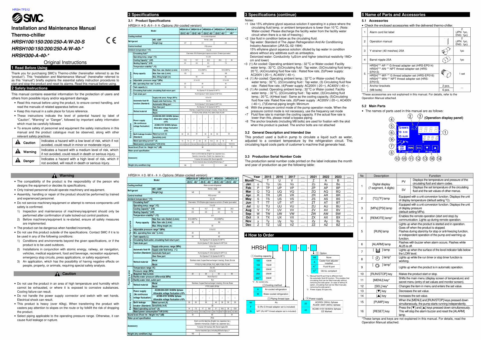
5.2 Main Parts
• The names of parts used in this manual are as follows:
No Description Function
1 Digital display
(7-segment, 4 digits)
PV Displays the temperature and pressure of the circulating fluid and alarm codes.
SV Displays the set temperature of the circulating fluid and the set values of other menus.
2 [oC] [oF] lamp Equipped with a unit conversion function. Displays the unit of display temperature (default setting oC).
3 [MPa] [PSI] lamp Equipped with a unit conversion function. Displays the unit of display pressure (default setting MPa).
4 [REMOTE] lamp* Enables the remote operation (start and stop) by communication. Lights up during remote operation.
5 [RUN] lamp
Lights up when the product is started and in operation. Goes off when the product is stopped. Flashes during stand-by for stop or anti-freezing function, or independent operation of the pump and warming up function.
6 [ALARM] lamp Flashes with buzzer when alarm occurs. Flashes while AL25 is off.
7 [ ] lamp Lights up when the surface of the level indicator falls below
the LOW level.
8 [ ] lamp* Lights up while the run timer or stop timer function is
working.
9 [ ] lamp*
Lights up when the product is in automatic operation.
10 [RUN/STOP] key Makes the product start or stop.
11 [MENU] key* Shifts the main menu (display screen of temperature) and secret menu (entry of set values and monitor screen).
12 [SEL] key* Changes the item in menu and enters the set value.
13 [] key Decreases the set value.
14 [] key Increases the set value.
15 [PUMP] key When the [MENU] and [RUN/STOP] keys pressed down simultaneously, the pump starts running independently.
16 [RESET] key Press the [] and [] keys pressed down simultaneously. This will stop the alarm buzzer and reset the [ALARM] lamp.
*These lamps and keys are not explained in this manual. For details, read the Operation Manual attached.
-20-S -40-* -20-S -40-* -20-S -40-* -20-S -40-*
HFC : GWP
Weight (kg)
Rate flow rate (Outlet) (L/min)
Max. flow rate (L/min)
Max. lifting height (m)
Supply side press. Range (M P a)
Supply side fluid temp. (oC)
Automactic filling port
Over flow port
Metal
Resin
AC200/200-230V 50/60Hz 3phase
Allow able voltage fluctuation
±10%
√ -- √ -- √ -- √ --
AC380-415V 50/60Hz 3phase
Allow able voltage fluctuation
±10%
-- √ -- √ -- √ -- √
Rated current (A) 30 20 40 30 50
Sensitivity (mA)
1 4 7.4 1 7 9.3 25 1 2.8 34 1 6
4.5 (4.9) 4.6 (5.1 ) 5.8 (6.0) 5.8 (6.4) 8.4 (8.7) 8.2 (8.9) 10.4 (11.6) 10.1 (11.1)
Y strainer (40 meshes) 25A, Barrel nipple 25A
Anchor brackets 2pcs.(including M 8 bolts 6pcs.)*8
280
30
18
1 0.8(1 2.3)
71
IPX4
Alarm cord list label 2pc.(English 1 pc./Japanese 1 pc.), Operation manual 2pc. (English 1 pc./Japanese 1 pc.),
1 80
Rc1/2 (Symbol F: G1/2, Symbol N: NPT1 /2)
Rc1 (Symbol F: G1, Symbol N: NPT1 )
Stainless, Copper(Heat exchanger’ s brazing ), Brass, Bronze
PTFE,PU, FKM , EPDM , PVC, NBR, POM , PE, NR
--
√
1 25 (0.5M Pa)
1 80
80
0.1 to 0.8
Air-coo led refrigerated
R41 0A : 2088
1.27 2.8
± 0.1
Cooling Capacity*3 (kW) 1 0.5 1 5.7
7.5
25.0
3.0 5.5
20.5
-40-*
PID contro l
- 5 to 45
HRSH300-A*HRSH150-A*
Circulating fluid*2
HRSH200-A* HRSH250-A*
Cooling method
HRSH100-A*Model
2.1
Ambient temperature *1 (oC)
1 30
50
Operating temp. range *1 (oC)
Clear water, 15% Ethylene glyco l aqueous so lution, DI water (pure water)
5 to 35
28
2.5
25 40
Refrigerant
Control method
45 (0.43M Pa) 45 (0.45M Pa)
Pump capacity
Heating Capacity*4 (kW)
1 20
Temperature stability*5 (oC)
21 5Weight (dry condition) (kg)
Earth leakage breaker
(Standard)
Rated operating current*5 (A)
Tank capacity (L) 25 42
Circulating fluid outlet, circulating fluid return port Rc1 (Symbol F: G1, Symbol N: NPT1 )
Sound level (Front 1m / Height 1m)*5 (dB)
Accessory
Rated power consumption*5 kW (kVA)
Tank drain port
Automatic fluid fill
function (Standard)
Rc3/4 (Symbol F: G3/4, Symbol N: NPT3/4)
0.2 to 0.5
5 to 35
68
Water-proof specification
30 30
Wetted material
Ele
ctr
ic s
ys
tem
Cir
cu
lati
ng
flu
id s
ys
tem
Pow er supply
(No continuous
voltage fluctuation)
60
Adjustable pressure range *6 (MPa) 0.1 to 0.5
Min. operating flow rate *7 (L/min) 20
(Operation display panel)
-20-S -40-* -20-S -40-* -20-S -40-* -20-S -40-*
HFC : GWP
Weight (kg)
Rate flow rate (Outlet) (L/min)
Max. flow rate (L/min)
Max. lifting height (m)
Supply side press. range (MPa)
Supply side fluid temp. (oC)
Automatic fluid port
Over flow port
Metal
Resin
Metal
Resin
AC200/200-230V 50/60Hz 3phase
Allowable voltage fluctuation ±10%√ -- √ -- √ -- √ --
AC380-415V 50/60Hz 3phase
Allowable voltage fluctuation ±10%-- √ -- √ -- √ -- √
Rated current (A) 30 20 40 30 50 30
Sensitivity (mA)1 4 7.3 1 7 8.8 2 1 1 0.6 25 1 2.8
4.2 (4.7) 4.4(5.0) 5.3 (5.8) 5.3 (6.1 ) 6.6 (7.0) 6.6(7.4) 8.0 (8.4) 8.2 (8.9)
60
Water-proof specification
Sound level (Front 1m / Height 1m)*5 (dB)
Power supply
(No continuous
voltage fluctuation)
Wetted materialStainless, Copper(Heat exchanger’ s brazing ), Bronze, Brass
Fa
cil
ity
wa
ter
sy
ste
m
30
M ore than 0.3
1.95
Rated power consumption*5 kW (kVA)
Ele
ctr
ic s
ys
tem
Earth leakage
breaker (Standard) 30
Facility water pressure differential (MPa)
Facility water inlet, outlet port Rc1
30
Weight (dry condition) (kg) 1 80
IPX4
Alarm cord list label 2pc.(English 1 pc./Japanese 1 pc.), Operation manual 2pc. (English 1 pc./Japanese 1 pc.),
Rated operating current*5 (A)
61
Accessory Y strainer (40 meshes) 25A, Barrel nipple 25A
61
1 50
Anchor brackets 2pcs.(including M 8 bolts 6pcs.)*8
5 to 40
Pressure range (MPa) 0.3 to 0.5
Required flow (L/min) 25 50 55
Temperature range (oC)
PTFE, NBR, EPDM
Wetted materialStainless steel, Copper(Heat exchanger’s brazing), Brass, Bronze
PTFE,PU, FKM , EPDM , PVC, NBR, POM , P E, NR
Automatic fluid fill
function (Standard)
0.2 to 0.5
5 to 35
Rc1/2 (Symbo l F: G1/2, Symbo l N: NPT1 /2)
Rc1 (Symbo l F: G1, Symbo l N: NPT1 )
Tank drain port Rc3/4 (Symbo l F: G3/4, Symbo l N: NPT3/4)
HRSH200- HRSH250-W*
Tank capacity (L) 25
Circulating fluid outlet, circulating fluid return port Rc1 (Symbo l F: G1, Symbo l N: NPT1 )
42
Model
± 0.1
Cooling Capacity*3 (kW) 11.5
2.5
Circulating fluid*2 Clear water, 1 5% Ethylene glycol aqueous so lution, DI water (pure water)
Operating temp. range *1 (oC)
4.0 7.2
Refrigerant 1.45
3.5
2 to 45
Cooling method Water-cooled refrigerated
Cir
cu
lati
ng
flu
id s
ys
tem
45 (0.43M Pa) 45 (0.45M Pa)
Temperature stability*5 (oC)
50
HRSH100-W*
Control method PID control
Ambient temperature *1 (oC)
R41 0A : 2088
130
HRSH150-W*
1 5.7
5 to 35
Adjustable pressure range *6 (MPa) 0.1 to 0.5
Min. operating flow rate *7 (L/min) 20 25
20.6 24.0
Heating Capacity*4 (kW)
120Pump capacity
HRSH-TFS12
5 Name of Parts and Accessories (continue)
Fig.1: HRSH***-A*-**-* (Air cooled type)
Fig.2: HRSH***-W*-**-* (Water cooled type)
6 Transportation, Transfer and Moving
6.1 Moving by forklift and slinging or by casters
Warning
• The product is a heavy object. (Refer to 3.1 Product specification for weights). • Moving by forklift and slinging should be done by persons who have required
licenses. • Moving the product by casters should be done by 2 persons or more
7 Installation
7.1 Installation
Warning
• Do not install the product unless the safety instructions have been read and understood.
7.2 Types of Hazard Labels
Warning
• The product has various potential hazards and they are marked with warning labels.
7 Installation (continue)
Warning related to Electricity
This symbol stands for a possible risk of electric shock.
Warning related to High Temperatures
This symbol stands for a possible risk of hot surface and burns.
Warning related to Rotating Objects
This symbol stands for a possible risk of cutting fingers or hand, or entanglement by rotating fan (For air-cooled type).
Warning related to other General Dangers
This symbol stands for general danger.
7.3 Environment
Warning
• Do not use in an environment where corrosive gases, chemicals, salt water or steam are present.
• Do not use the product in an area of high temperature and humidity which cannot be exhausted, or where it is exposed to corrosive substances. Cooling failure can result.
• Do not use in an explosive atmosphere. • Do not use in locations at altitudes of 3000m or higher (except for
product storage and transport), refer to the Operation Manual. • Do not install in a location exposed to direct sunlight and radiant heat.
• Do not install in a location subject to vibration or impact. • Do not install in locations that is exposed to the splash of water that is
higher than IPX4. • Do not expose to potential lighting strike. 7.4 Mounting
Warning
• The Installer / End User is responsible for carrying out a noise risk assessment on the equipment after installation and taking appropriate measures as required.
Caution
• Have enough space for ventilation for the product. Otherwise may cause a lack of cooling capacity or/and stoppage of the product.
• Have enough space for maintenance.
• Install the product on a vibration free floor.
• Prepare M10 anchor bolts that are suitable to the floor that the product will be installed. Refer to operation manual for outline dimensions for the position of the anchor bolts.
Recommend installation space
7 Installation (continue)
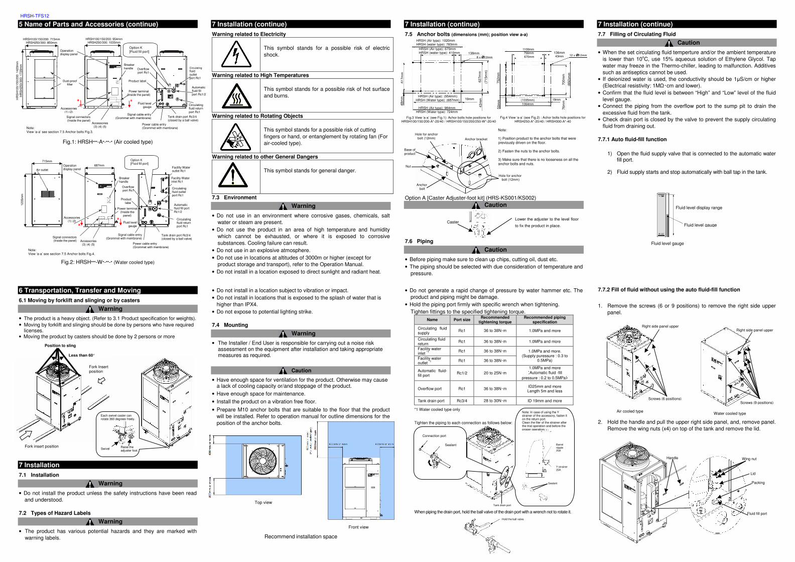
7.5 Anchor bolts (dimensions (mm); position view a-a)
Option A [Caster Adjuster-foot kit] (HRS-KS001/KS002) Caution
7.6 Piping
Caution
• Before piping make sure to clean up chips, cutting oil, dust etc. • The piping should be selected with due consideration of temperature and
pressure.
• Do not generate a rapid change of pressure by water hammer etc. The product and piping might be damage.
• Hold the piping port firmly with specific wrench when tightening. Tighten fittings to the specified tightening torque.
Name Port size Recommended
tightening torque Recommended piping
specification
Circulating fluid supply Rc1 36 to 38N・m 1.0MPa and more
Circulating fluid return
Rc1 36 to 38N・m 1.0MPa and more
Facility water inlet *1
Rc1 36 to 38N・m 1.0MPa and more. (Supply puressure : 0.3 to
0.5MPa) Facility water outlet *1 Rc1 36 to 38N・m
Automatic fluid-fill port
Rc1/2 20 to 25N・m 1.0MPa and more (Automatic fluid -fill
pressure : 0.2 to 0.5MPa)
Overflow port Rc1 36 to 38N・m ID25mm and more Length 5m and less
Tank drain port Rc3/4 28 to 30N・m ID 19mm and more
*1 Water cooled type only
Tighten the piping to each connection as follows below:
When piping the drain port, hold the ball valve of the drain port with a wrench not to rotate it.
7 Installation (continue)
7.7 Filling of Circulating Fluid
Caution
• When the set circulating fluid temperture and/or the ambient temperature is lower than 10oC, use 15% aqueous solution of Ethylene Glycol. Tap water may freeze in the Thermo-chiller, leading to malfunction. Additives such as antiseptics cannot be used.
• If deionized water is used, the conductivity should be 1µS/cm or higher (Electrical resistivity: 1MΩ・cm and lower).
• Confirm that the fluid level is between “High” and “Low” level of the fluid level gauge.
• Connect the piping from the overflow port to the sump pit to drain the excessive fluid from the tank.
• Check drain port is closed by the valve to prevent the supply circulating fluid from draining out.
7.7.1 Auto fluid-fill function
1) Open the fluid supply valve that is connected to the automatic water
fill port.
2) Fluid supply starts and stop automatically with ball tap in the tank.
7.7.2 Fill of fluid without using the auto fluid-fill function
1. Remove the screws (6 or 9 positions) to remove the right side upper panel.
2. Hold the handle and pull the upper right side panel, and, remove panel.
Remove the wing nuts (x4) on top of the tank and remove the lid.
Fluid level gauge
Fluid level display range
Fluid level gauge
Handle
Wing nut
Lid
Fluid fill port
Packing
Water cooled type Air cooled type
Screws (6 positions)
Right side panel upper
Screws (9 positions)
Right side panel upper
Sealant
Connection port
Note: In case of using the Y strainer of the accessory, fasten it on the return port. Clean the filer of the strainer after the trial operation and before the proper operation
Sealant
Barrel nipple 25A
Y strainer 25A
Tank drain port
Position to sling
Less than 60°
Fork insert position
Fork Insert position
Raise the adjuster foot. Swivel
Each swivel caster can rotate 360 degrees freely.
Hold the ball valve.
Lower the adjuster to the level floor
to fix the product in place. Caster
Note: 1) Position product to the anchor bolts that were previously driven on the floor. 2) Fasten the nuts to the anchor bolts. 3) Make sure that there is no looseness on all the anchor bolts and nuts.
Note: View ‘a-a’ see section 7.5 Anchor bolts Fig.4.
Tank drain port Rc3/4 (closed by a ball valve)
Circulating fluid return port Rc1
Air outlet
Circulating fluid outlet port Rc1
Automatic fluid fill port Rc1/2
Overflow port Rc1
Signal cable entry (Grommet with membrane)
Power cable entry (Grommet with membrane)
Product label
Fluid level gauge
Option K [Fluid fill port]
Power terminal (Inside the
panel)
Signal connectors (Inside the panel)
Operation display panel
Accessories (3) (4) (5)
Accessories (1) (2)
Breaker handle
Facility Water outlet Rc1 Facility Water inlet Rc1
1235
mm
715mm
687mm
a
a
Fig.3 View ‘a-a’ (see Fig.1): Achor bolts hole positions for HRSH100/150/200-A*-20/40 / HRSH100/150/200/250-W*-20/40
Fig.4 View ‘a-a’ (see Fig.2) : Achor bolts hole positions for HRSH250-A*-20/40 / HRSH300-A*-40
756mm
(1035mm) 1064mm
12 x ∅∅∅∅12mm 43mm 136mm
19mm
752m
m
50m
m
76m
m
700m
m
(850
)mm
670mm
1100mm
Anchor bolt
Base of product
Hole for anchor bolt (12mm)
Hole for anchor bolt (12mm)
Anchor bracket
Nut
617m
m
627m
m
(715
mm
)
HRSH (Air type): 1020mm HRSH (water type): 760mm
HRSH (Air type): (954mm) HRSH (Water type): (687mm)
138mm 8 x ∅∅∅∅12mm
48m
m
43m
m
19mm
HRSH (Air type): 670mm HRSH (water type): 410mm
HRSH (Air type): 984mm HRSH (Water type): 724mm
Top view
Front view
a a
Note: View ‘a-a’ see section 7.5 Anchor bolts Fig.3.
Breaker handle Overflow
port Rc1
HR
SH
100/
150/
200:
142
0mm
H
RS
H25
0/30
0: 1
720m
m
Operation display panel
Tank drain port Rc3/4 (closed by a ball valve)
Circulating fluid outlet port Rc1
Circulating fluid return port Rc1
Automatic fluid fill port Rc1/2
Signal cable entry (Grommet with membrane)
Power cable entry (Grommet with membrane)
Product label
Fluid level gauge
Option K [Fluid fill port]
Dust-proof filter
Power terminal (Inside the panel)
Signal connectors (Inside the panel)
Accessories (3) (4) (5)
Accessories (1) (2)
HRSH100/150/200: 715mm HRSH250/300: 850mm
HRSH100/150/200: 954mm HRSH250/300: 1035mm

HRSH-TFS12
ON ⇒
Press
Flash ⇔ Example: “AL01” “Low level in tank”
Press
→The initial screen (HELLO) will be displayed for approx. 8 seconds on the operation panel. Then the display changes to the main screen which displays the circulating fluid outlet temperature.
7 Installation (continue)
3. Fill the circulating fluid in the fluid port
7.8 Wiring of Power Supply Cable
Warning
• The electrical facilities should be installed and wired in accordance with local laws and regulations of each country and by the person who has knowledge and experience.
• Check the power supply. Operation with voltages, capacities, frequencies and cable sizes other than those specified can cause heat, fire and electrical shock.
• Wire with an applicable cable size and terminal. • Be sure to shut off the user’s power supply. Wiring with the product
energized is strictly prohibited.
Caution
• Use an individual socket or earth leakage breaker. • Be sure to provide grounding. Incomplete grounding can cause failure
and electrical shock. • When panel is removed or mount, be sure to wear protective shoes and
gloves to prevent injury with the edge of the panel.
7.8.1 Preliminary Preparation for Wiring
Prepare the power supply shown in the following table. For the
connection between the product and power supply, use the power supply
cable and earth leakage breaker shown below:
7.8.2 Wiring of Power Supply
1) Turn off the breaker handle. 2) Remove four screws to remove the front panel. 3) Hold the handle and pull up the front panel of the electrical unit, and
remove.
7 Installation (continue)
4) Connect the power supply cable and ground cable as shown below:
∗ Connect over current protection to the power cable connected to the equipment in order to avoid hazard.
8 Start, Stop and Temperature Settings
8.1 Preliminary Preparation for Start-up
8.1.1 Supply of Power
1) Turn on the breaker handle. 8.1.2 Preparation of circulating fluid
1) Press the [PUMP] key ([RUN/STOP] key and [MENU] key simultaneously). The [RUN] lamp flashes and only the pump continues
the operation. This operation allows the discharge of the circulating fluid, and enables checking leakage from the piping and air release.
2) At this time, the fluid level can lower and cause the alarm “AL01; Low tank level", which will lead to the stop of the product.
3) In that case, check that there is no leakage from the user’s piping, fill the circulating fluid as specified in “7.6 Filling of Circulating Fluid” and take necessary actions in “9. Reset Alarms”.
4) Repeat steps 1) to 3) until the alarm (“AL01; Low tank level”) is no longer generated.
8.1.3 Temperature Setting
1) Press the [] and [] keys to change the SV to the required value.
8.2 Start of the Product
1) Press the [RUN/STOP] key pressed for approx. 2 seconds . ⇒The [RUN] lamp lights up (in green) and the product starts running.
The circulating fluid discharge temperature (PV) is controlled to the set temperature (SV).
8 Start, Stop and Temperature Settings (continue)
8.3 Stop of the Product
1) Press the [RUN/STOP] key ⇒The [RUN] lamp flashes (in green) and continues the operation until the product is ready to stop. After approx. 20 seconds, the [RUN] lamp goes off and the product stops.
9 Reset Alarms
Caution
• Should some error occur, the [ALARM] lamp flashes (in red) and the buzzer sounds to inform the user of the ‘Error’.
• The alarm code will be displayed on the operation panel so that the cause can be checked on “Troubleshooting”.
• Before resetting the alarm, read the “Causes and Remedies” of “Troubleshooting” and eliminate the cause explained there. Otherwise, the same alarm may be repeated.
• As accessories, the alarm code list label are enclosed. Stick the label to the panel to check the contents of alarm codes.
Reset of alarm
1) Press the [RESET] key ([] and [] keys simultaneously). ⇒The buzzer and then [ALARM] lamp (red) go off.
10 Maintenance
10.1 General Maintenance
Warning
• Do not operate switches, etc. with wet hands and do not touch the electrical parts such as the power supply plug. It might cause electric shock.
• Do not splash water directly on the product and do not wash with water. It might cause electric shock and fire, etc.
• Do not touch the fins directly when cleaning the dustproof filter. It might cause injury.
• Remount all panels removed for inspection or cleaning. As this might cause injury or electric shock if the prodcut is operated without the panels.
Caution
• Not following proper maintenance procedures could cause the product to malfunction and lead to equipment damage.
• Before performing maintenance, turn off the power supply. After installation and maintenance, turn on power to the equipment and perform appropriate functional and leakage tests to make sure the equipment is installed correctly.
• Do not make any modification to the product.
• Do not disassemble the product, unless required by installation or maintenance instructions.
10 Maintenance (continue)
10.2 Control of Circulating Fluid Quality
Warning
• Use specified circulating fluids only. If other fluids are used, they may damage the product or result in dangerous hazards.
• When using fresh tap water ensure that it satisfies the water standard shown in the Operation Manual.
10.3 Daily Check
Caution
• Check each item of “Daily checklist”, and if any error is seen, stop the operation of the product and turn off the user's power supply, and service the product.
Daily checklist
Item Description of checking
Installation condition Check the installation
conditions of the product.
There is no heavy object on the product or excessive force on the piping. Temperature and humidity are within the specified range of the product.
Fluid leakage Check the connected part of piping
There is no circulating fluid leakage from the connected part of piping.
Fluid amount Check the liquid level indicator.
The circulating fluid must enter the scale of ‘’H’’.
Operation panel
Check the display. The numbers on the display are clear.
Check the function. The [RUN/STOP] and [MENU],[SEL],[],[] buttons operate properly.
Circulating fluid temperature Check on the operation panel. There is no problem for use.
Circulating fluid flow rate
Check on the operation panel. There is no problem for use. If flow rate decreasing, please check and clean the Y-strainer.
Operating conditions Check the operation condition. There is no abnormal noise, vibration, smell and smoke.
Facility water (water cooled type)
Facility water condition Temperature, puressure and flow rate are within the specified range of the product.
10.4 Monthly Check
Cleaning of air vent (For air-cooled type) Caution
• If the air ventilation of the product have clogged with dust or debris, heat radiation performance reduces. This results in the reduction of cooling performance, and may stop the operation.
10.4.1 Removal of the Dustproof Filter
1) The dust-proof filters are installed on the front and left side of the product. In total there are four filters with the same shape.
2) The dustproof filters can be removed as shown in the below drawing. Care should be taken not to deform or scratch the air-cooled condenser.
10.4.2 Cleaning of Filter
1) Clean the dust filter with a long bristled brush or by air purging.
2) Mount the dustproof filter in reverse order of removal.
Model Power supply voltage
Terminal block screw
diameter
Recommend crimp terminal
Cable qty. x
size
Earth leakage breaker
Rated
current
[A]
Sensitivity
of leak
current
[mA]
HRSH100-A*-20-S HRSH100-W*-20-S
AC200/ 200~230V 50/60Hz 3 phase
M5
R5.5-5 4 corexAWG10
(4coresx 5.5mm2) *including ground
30
30
HRSH150-A*-20-S HRSH150-W*-20-S
HRSH200-A*-20-S HRSH200-W*-20-S
R8-5 4 corexAWG8
(4cores x 8mm2) *including ground
40
HRSH250-A*-20-S HRSH250-W*-20-S 50
HRSH100-A*-40-* HRSH100-W*-40-*
AC380-415V
50/60Hz 3 phase
M5
R5.5-5 For power line
3x5.5mm2 (3xAWG10)
20
30
HRSH150-A*-40-* HRSH150-W*-40-*
30 HRSH200-A*-40-* HRSH200-W*-40-* R14-5
For ground line
1x14mm2 (1xAWG6) For ground line
HRSH250-A*-40-* HRSH250-W*-40-* HRSH300-A*-40-*
OFF ⇒
Press
Off Press together.
L1 L2 L3 PE
Inlet of the power supply cable.
Note: Prepare a cable tie. Fasten the power cable to the mount on the base by the cable tie.
ON
OFF
Note: Please turn off the breaker handle. The front panel of the electrical unit cannot be removed without turning off the breaker.
Screw Screw
Front panel for the electrical unit
Handle
Example: Filling the fluid to the port. Option K (Fluid fill port) Open cap of the fluid port and fill with circulating fluid.
Cleaning with brush Cleaning by air purging
HRSH-TFS12
10 Maintenance (continue)
10.5 Inspection Every 3 Months
10.5.1 Replacement of Circulating Fluid
• Replace the exiting circulating fluid with new circulating fluid periodically. Otherwise algae or decompose may occur.
• In case of using the Y strainer (accessory), clean the screen mesh in the strainer when exchanging the circulating fluid. - Ensure that there is no circulating fluid left in the product, customer’s
machine and piping. - Remove the cap cover of the strainer and take out the screen mesh and
clean with detergent or/and purge by air. Take care not to damage the screen mesh.
- Do not use any chlorinated detergents and cleansers. 10.5.2 Replacement of Facility Water (For water cooled type)
• Clean the facility water source and replace the facility water. Caution
• If there is foreign matter or clogging in the screen mesh, the pressure loss will become large and may break the screen mesh.
10.6 Inspection for winter season
Caution
• The power supply should be ‘ON’ for these functions. Otherwise these functions cannot start.
Anti- freezing function: To prevent the circulating fluid freezing during winter, this function operates pump automatically to heat the circulating fluid by the pump’s heat radiation. (For details refer to operation manual)
Warming up function: During winter or night, this function operates pump automatically to heat the circulating fluid by the pump’s heat radiation to keep the circulating fluid temperature around the warming up function set temperature. (For details refer to operation manual)
Anti-snow coverage function (air cooled type): To prevent the snow coverage on the ventilation air outlet of the fan in winter, this function operates fan automatically. (For details refer to operation manual)
Freezing of the facility water: Discharge the facility water circuit when there is fear of a freeze (Refer to 12.7.2).
10.7 Discharge of the Circulating Fluid and Facility Water
Warning
• Stop the customer device and release the residual pressure before discharging the circulating fluid.
• Before discharging the facility water, in case of water-cooled refrigerated type, stop the equipment for the facility water, or stop the facility water circuit to release the residual pressure.
10.7.1 Drain of the circulating fluid
1) Shut of the breaker of the customer’s power supply. 2) Close the valve that is connected to the auto-fill port by the customer. 3) Open the ball valve of the drain port and drain the fluid. 4) Confirm all the circulating fluid has been drained from the product,
user’s machine and piping, and, apply air purge from the circulating fluid return port.
5) After draining the circulating fluid, close the ball valve of the drain port. 10.7.2 Drain of facility water (water-cooled type)
Warning
• Stop the customer device and release the residual pressure before draining the facility water
1) Shut the breaker of the customer’s power supply. 2) Stop supply the facility water and make sure there is no pressure in
the facility water piping. 3) Remove the facility water piping from the product. 4) Open the front panel then, open the air vent valve. The facility water
in the product will be drained from the facility water inlet port.
10 Maintenance (continue)
5) After draining, shut the air valve and close the front panel. 10.8 Consumable Parts
Part No. Description Qty Remark
HRS-S0213 Dust-proof filter (Upper) 1 HRSH100/150/200-A: 2pcs used per unit
HRS-S0214 Dust-proof filter (Lower) 1 HRSH150/200-A: 2 pcs used per unit
HRS-S0185 Dust-proof filter 1 HRSH250/300-A: 4 pcs used per unit
11 Troubleshooting
11.1 Troubleshooting
The troubleshooting method depends on which alarm has been generated. Refer to the ”Alarm code list and Troubleshooting”.
Warning
• In the event of an unexpected problem or malfunction, switch off the product and investigate the cause. If the cause of the problem cannot be determined, do not use the product, but contact SMC for assistance.
Alarm code list and Troubleshooting
Code Description Operation Cause/Remedy
(Press the reset key after eliminating the cause.)
AL01 Low level in tank A.STP The fluid level of the level indicator has fallen. Fill the circulating fluid.
AL02 High circulating fluid discharge temp.
A.STP ・Check that the ambient temperature, facility water specifications and heat load are within the specified ranges. ・Check circulating flow rate to keep minimum operating flow rate by check monitor menu. ・Check the value of . ・Wait until the circulating fluid temperature lowers.
AL03 Circulating fluid discharge temp. rise
A.RUN
AL04 Circulating fluid discharge temp. drop
A.RUN ・Check that the filled circulating fluid temperature is within the specified range. ・Check the value of .
AL05 High circulating fluid return temp.
A.STP ・Check that the circulating fluid flows. ・Check that the heat load is within the specified range.
Code Description Operation Cause/Remedy
(Press the reset key after eliminating the cause.)
AL08 Circulating fluid discharge pressure rise
A.STP
Check that there is no bend, collapse and clog on/in the external piping. In case of displaying EEEE on the PV display of the main display and check monitor menu, the pressure sensor of the circulating fluid circuit has a malfunction. Ask for service.
AL09 Circulating fluid discharge pressure drop
A.STP
Restart and check if the pump runs. In case of displaying EEEE on the PV display of the main display and check monitor menu, the pressure sensor of the circulating fluid circuit has a malfunction. Ask for service.
AL10 High compressor suction temp.
P.RUN
・Check the returned circulating fluid temperature. ・Check that the heat load is within the specified range.
AL11 Low compressor suction temp.
P.RUN ・Check that the circulating fluid flows. ・Use 15% ethylene glycol aqueous solution with the set temperature lower than 100C. AL12
Low super heat temperature
P.RUN
AL13 High compressor discharge pressure
P.RUN Check that the ambient temperature, facility water specifications and heat load are within the specified ranges.
AL15 Refrigerant circuit pressure (high pressure side) drop
P.RUN Malfunction of the refrigeration circuit occurred. Ask for the service.
AL16 Refrigerant circuit pressure (low pressure side) rise
P.RUN Check that the ambient temperature, facility water specifications and heat load are within the specified ranges.
AL17 Refrigerant circuit pressure (low pressure side) drop
P.RUN Check that the circulating fluid flows higher than the minimum operating flow rate.
AL18 Compressor running failure P.RUN
Restart and check if the compressor runs after leaving for 10 minutes.
AL19 Communication error
OFF No request message is sent from the host computer. Send it again.
AL20 Memory error A.STP Malfunction of the controller occurred. Ask for service.
AL21 DC line fuse cut A.STP
Fuse for the power supply output of the contact input/output connector has blown. ・Ask for service. ・Check that there is no incorrect wiring and the current load is within the specified range.
AL22 Circulating fluid discharge temp. sensor failure
A.STP Malfunction of the temperature sensor occurred. Ask for service.
11 Troubleshooting (continue)
Code Description Operation Cause/Remedy
(Press the reset key after eliminating the cause.)
AL23 Circulating fluid return temp. sensor failure
A.STP Malfunction of the temperature sensor occurred. Ask for service.
AL24 Compressor suction temp. sensor failure
P.RUN
AL25 Circulating fluid discharge pressure sensor failure
A.STP
Malfunction of the pressure sensor for the circulating fluid circuit occurred. EEEE is displayed on the PV display of the main display and check monitor display. Ask for service.
AL26 Compressor discharge pressure sensor failure
P.RUN Malfunction of the pressure sensor for the refrigeration circuit occurred. Ask for service.
AL27 Compressor suction pressure sensor failure
P.RUN
AL28 Pump maintenance OFF Notices of the periodical maintenances. Ask for services of the pump, fan and/or compressor. Each periodical time can reset by , and .
Every 20,00h
AL29*1 Fan maintenance OFF Every 30,00h
AL30 Compressor maintenance
OFF Every 30,00h
AL31 Contact input 1 signal detection
A.STP Contact input is detected.
AL32 Contact input 2 signal detection
A.STP
AL37 Compressor discharge temp. sensor failure
P.RUN Malfunction of the temperature sensor occurred. Ask for service.
AL38 Compressor discharge temp. rise
P.RUN Check that the ambient temperature, facility water specifications and heat load are within the specified ranges.
AL39 Internal unit fan stoppage
A.RUN Malfunction of the internal unit fan occurred. Ask for service.
AL40 Dust-proof filter maintenance OFF
Notice of the periodical maintenance. Clean the dust-proof filter. This periodical time can reset by
. And can off this alarm.
1 to 9999h ( )
AL41 Power stoppage A.STP The power was shut off during running. Restart after checking the power supply.
AL42 Compressor waiting A.RUN The system is waiting for the compressor to be ready to run. Wait for a while. Will be automatically released after running.
Code Description Operation Cause/Remedy
(Press the reset key after eliminating the cause.)
AL43*1 Fan breaker trip P.RUN
Check that there is no power failure such as ground fault, short circuit, voltage fluctuation, abnormal interphase voltage, open phase, surge.
Release the fan breaker trip refer to the operation manual.
AL44*1 Fan inverter error P.RUN
AL45 Compressor breaker trip
P.RUN Press the [] and [] keys of the operation display panel pressed down simultaneously for 10 seconds to reset. After resetting AL48, WAIT( ) will be displayed and the product cannot run for 40 seconds. Restart 40 seconds later after resetting.
AL46 Compressor inverter error
P.RUN
AL47 Pump breaker trip A.STP
AL48 Pump inverter error A.STP
AL49*2 Internal unit fan stoppage
A.RUN Malfunction of the air exhaust fan occurred. Ask for the service.
Note: *1: This alarm does not occur on the product of water cooled type. *2: This alarm does not occur on the product of air cooled type. A.STP: Stop the pump, compressor and fan with alarm. A.RUN: Continues running the pump, compressor and fan with alarm. P.RUN: Stop the compressor and fan, and, continues running the pump with alarm. OFF: Does not generate alarm.
11.2 Other Errors
The causes and remedies for failures that are not indicated by alarm numbers are shown in the following table:
Content of Failure Cause Remedy
The operation panel
displays nothing
The breaker of the customer’s power supply or/and the optional breaker is/are not turned on.
Turn on the breaker.
Failure of the breaker of the customer’s power supply or/and optional power supply.
Replace the breaker.
No power supply (The breaker for the power supply is not turned on.)
Supply the power.
Breaker trip of the customer’s power supply or/and the optional breaker due to short-circuit and current leakage.
Repair the short-circuit or
current leaking part.
11 Troubleshooting (continue)
Content of Failure Cause Remedy
The [RUN] LED does not
light up even when the
[RUN/STOP] switch is
pressed.
Communication is set. Set the communication in the
local mode.
Failure of the [RUN] LED Replace the controller.
Failure of the [RUN/STOP]
switch Replace the controller.
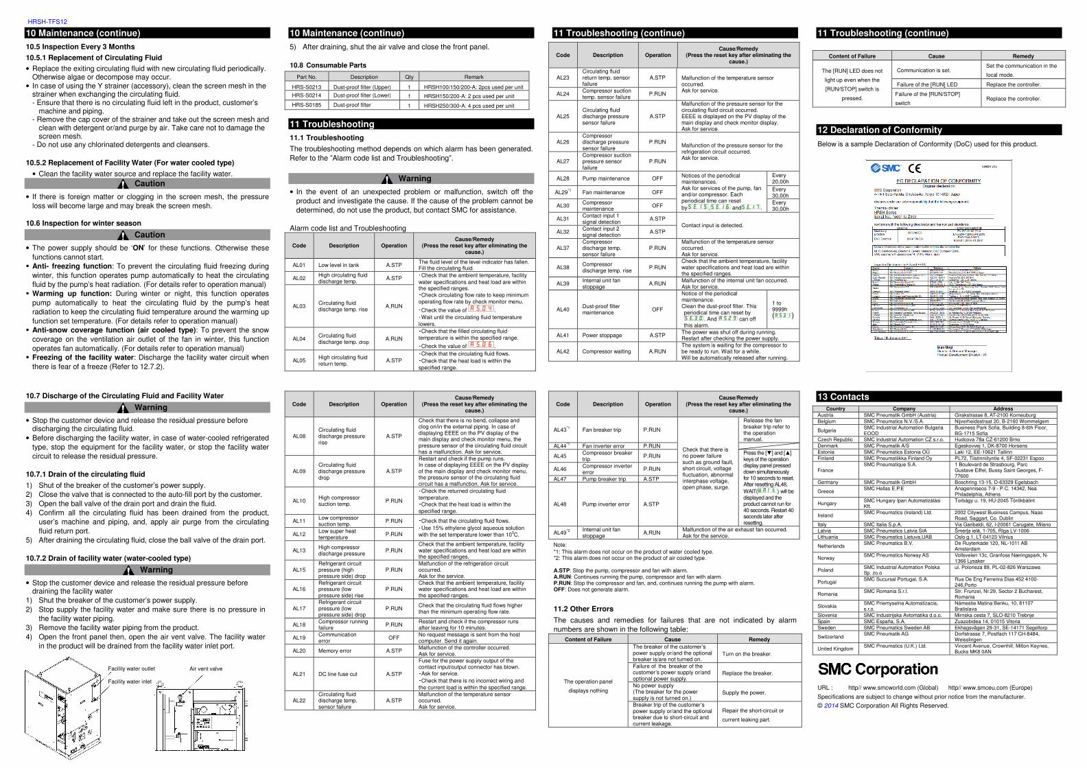
12 Declaration of Conformity
Below is a sample Declaration of Conformity (DoC) used for this product.
13 Contacts
Country Company Address
Austria SMC Pneumatik GmbH (Austria) Girakstrasse 8, AT-2100 Korneuburg Belgium SMC Pneumatics N.V./S.A. Nijverheidsstraat 20, B-2160 Wommelgem
Bulgaria SMC Industrial Automation Bulgaria EOOD
Business Park Sofia, Building 8-6th Floor, BG-1715 Sofia
Czech Republic SMC Industrial Automation CZ s.r.o. Hudcova 78a CZ-61200 Brno Denmark SMC Pneumatik A/S Egeskovvej 1, DK-8700 Horsens Estonia SMC Pneumatics Estonia OÜ Laki 12, EE-10621 Tallinn Finland SMC Pneumatiikka Finland Oy PL72, Tiistinniityntie 4, SF-02231 Espoo
France SMC Pneumatique S.A. 1 Boulevard de Strasbourg, Parc
Gustave Eiffel, Bussy Saint Georges, F-77600
Germany SMC Pneumatik GmbH Boschring 13-15, D-63329 Egelsbach
Greece SMC Hellas E.P.E Anagenniseos 7-9 - P.C. 14342, Nea Philadelphia, Athens
Hungary SMC Hungary Ipari Automatizálási Kft.
Torbágy u. 19, HU-2045 Törökbálint
Ireland SMC Pneumatics (Ireland) Ltd. 2002 Citywest Business Campus, Naas
Road, Saggart, Co. Dublin Italy SMC Italia S.p.A. Via Garibaldi, 62, l-20061 Carugate, Milano Latvia SMC Pneumatics Latvia SIA Šmerļa ielā, 1-705, Rīga LV-1006 Lithuania SMC Pneumatics Lietuva,UAB Oslo g.1, LT-04123 Vilnius
Netherlands SMC Pneumatics B.V. De Ruyterkade 120, NL-1011 AB
Amsterdam
Norway SMC Pneumatics Norway AS Vollsveien 13c, Granfoss Næringspark, N-1366 Lysaker
Poland SMC Industrial Automation Polska Sp. zo.o
ul. Poloneza 89, PL-02-826 Warszawa
Portugal SMC Sucursal Portugal, S.A. Rua De Eng Ferrerira Dias 452 4100-246,Porto
Romania SMC Romania S.r.l. Str. Frunzei, Nr.29, Sector 2 Bucharest, Romania
Slovakia SMC Priemyselna Automatizacia, s.r.o.
Námestie Matina Benku, 10, 81107 Bratislava
Slovenia SMC Industrijska Avtomatika d.o.o. Mirnska cesta 7, SLO-8210 Trebnje Spain SMC España, S.A. Zuazobidea 14, 01015 Vitoria Sweden SMC Pneumatics Sweden AB Ekhagsvägen 29-31, SE-14171 Segeltorp
Switzerland SMC Pneumatik AG Dorfstrasse 7, Postfach 117 CH-8484,
Weisslingen
United Kingdom SMC Pneumatics (U.K.) Ltd. Vincent Avenue, Crownhill, Milton Keynes, Bucks MK8 0AN
URL : http// www.smcworld.com (Global) http// www.smceu.com (Europe)
Specifications are subject to change without prior notice from the manufacturer.
© 2014 SMC Corporation All Rights Reserved.
Air vent valve
Facility water outlet
Facility water inlet