hrpp 402 new lng marine terminals - hr wallingford
TRANSCRIPT

Site selection and planning issues for new LNG marine terminals
HRPP
402
Stephen Cork and Ridha Bentiba
Reproduced from a paper presented at: PIANC-COPEDEC 23-28 February 2008Dubai, UAE


Site selection and planning issues for new LNG marine terminals PIANC-COPEDEC 2008, Dubai, UAE
2008 1 HRPP 402
SITE SELECTION AND PLANNING ISSUES FOR NEW LNG MARINE TERMINALS Stephen Cork1 and Ridha Bentiba2 1 Technical Director, HR Wallingford UK, Chairman PIANC UK Section 2Project Engineer, HR Wallingford UK ABSTRACT This paper considers the site selection and planning issues associated with the development of new LNG import and export marine terminals. It describes the current LNG fleet and recent developments in vessel sizes and the basic operational and design criteria required for LNG terminal development.The key objectives early in the planning and design stages are to define the environmental parameters and operational performance needs of the terminal. The integration of environmental conditions and operational criteria to optimise terminal development can then be undertaken by applying terminal operational simulation techniques. Some actual case studies are presented in the paper, which have used these techniques in the planning and development of new LNG Terminals. 1 INTRODUCTION Liquid Natural Gas (LNG) is natural gas, liquefied by reducing its temperature to minus 161 degrees Celsius at atmospheric pressure, usually to allow for transportation by ship. This process reduces the volume of gas by a factor of 600, producing a liquid with a density of less than half that of water. Typically the composition of LNG is 85 to 95+ percent methane, along with a few percent ethane, even less propane and butane, and possibly traces amounts of nitrogen. When it reaches its destination, it is stored in liquid refrigerated form until use, then re-gasified, and injected into pipeline systems. Over the last decade there has been steady increase in activity in the LNG industry. World LNG trade reached 85.8 MMT in the first half of 2007, showing an 8% increase compared to the same period in 2006. Currently (as at Dec 2007) there are nine new LNG production (export) plants under construction (in Norway, Australia, Peru, Qatar, Russia, Indonesia and Yemen) with a further 15 planned (in Angola, Australia, Indonesia, Iran, Nigeria, Papua New
Figure 1: LNG Berth in operation Guinea, Russia and Venezuela). Re-gasification (import) plants are even more numerous in the receiving countries, with 19 currently under construction and over forty more at planning stage. LNG trade is set to dramatically increase over the next decade with the development of these new production facilities and growth in demand from existing and new

Site selection and planning issues for new LNG marine terminals PIANC-COPEDEC 2008, Dubai, UAE
2008 2 HRPP 402
importers such as the developing countries of India and China. The upsurge in LNG marine transportation has created an unprecedented demand for new marine terminal facilities, both at the point of LNG production and at the point of reception. In general the sites of these new LNG marine terminals are not associated with historically developed commercial ports and are likely to be green field/blue sea developments. Little historical data is normally available for these remote sites and optimisation of the siting and layout of new LNG terminals requires detailed investigations and studies to ensure appropriate facilities can be built and operated satisfactorily. The requirements for the ideal LNG marine terminal location are: • To be located close to the gas
supply/delivery location • To have suitable onshore areas for tank
storage and liquefaction/re-gasification plant
• To provide safe marine access to berth(s)
• To be located in sheltered water close to storage tanks and liquefaction of re-gasification plant
• To be remote from any existing commercial marine operations or centres of population
If these criteria are not available naturally then there will be a need for them to be
artificially created by dredging of access channels and manoeuvring areas, creation of protected water areas using breakwaters or moving tanks/plant offshore. The key objectives to be considered at planning stage are to ensure minimal risk to safe marine access and ensure safe conditions for loading/unloading operations, minimise the construction and operational costs and implementation schedule and mitigate any risks to construction and operations. 2 GROWTH OF LNG FLEET According to the “LNG World Shipping”, the world fleet of LNG carriers is expanding exponentially. The numbers crossed the 200-vessel mark in April 2006 and is set to increase to 300 by the end of 2008. It took 34 years to 1998 for the in-service fleet of LNG carriers to reach 100 vessels, then eight years to reach the current level. The next 100 ships, however, will take just two more years to enter service. LNG carriers now in service vary in capacity from the smallest of about 20,000 m3 to the world's largest LNG carriers, the 266,000 m3 Q-max LNG carriers recently ordered by QatarGas. The majority currently in operation are in the 125-150,000m3 range. The containment methods for the LNG carried on these vessels are generally one of four types: Gaz Transport membrane, Technigas membrane, Kvaerner Moss spherical and IHI SPB prismatic tank.
Figure 2: Typical Moss spherical LNG Tanker

Site selection and planning issues for new LNG marine terminals PIANC-COPEDEC 2008, Dubai, UAE
2008 3 HRPP 402
Table 1: Typical LNG vessel dimensions Vessel size 70-80,000m3 125-150,000m3 Q-Flex Q-Max Type Various Spherical /
membrane Membrane Membrane
Capacity (m3) 75,000 125-150,000 Up to 217,000 Up to 266,000 LOA* (m) 257 288-294 315 345 Beam (m) 34.8 42-48 50 53.8 Design draught (m) 9.5 11.3-12.3 12-12.5 12 *LOA – length overall Typical dimensions of a range of LNG vessels currently in operation are shown in the table above. 3 BASIC DESIGN CRITERIA The initial criteria to be defined at the start of the project are: • Size and type of vessel to be
accommodated. This will affect the basic layout of the terminal and the depth of water required. Consideration must be given to future requirements in terms of larger vessels or additional berths. This is particularly true for new start-up facilities where smaller vessels (e.g. 50,00m3) may be the optimum size initially, but where future demand requires larger vessels to be handled at the terminal. Careful consideration must be given to the level of pre-investment in sizing the initial terminal, and the expansion strategy to be adopted in terms of wider/deeper channels, breakwater expansion and jetty capacity to cater for the larger vessels required in the future.
• Allowable downtime, if any. This is an important consideration to determine the degree of protection to be provided at the operating berth. If some downtime can be accommodated then the cost of berth protection can be reduced, although this is not normally the case since dedicated ships operating to a fixed schedule would be affected.
• Acceptable ship motion during cargo transfer. Again this is a function of the degree of protection to be provided at the berth. Transfer of LNG is made using marine loading/unloading arms which can accommodate a degree of vessel movement at the berth.
The above criteria will allow the required depth of water and the degree of shelter required to be determined at the start of the project. At this initial stage it is important that these requirements are fully defined and agreed with the potential operator or developer, since once the site is selected it may be extremely difficult to change the design vessel size and operational profile.
4 OPERATIONAL CRITERIA Based on experiences around the world, the following operational wind speeds are considered to be general limits for LNG tankers in ballast condition during operations: • Approximately 10-12 m/sec or 20-24
knots during berthing operations • Approximately 17 m/sec or 35 knots
during loading and unloading operation.
• The loading arms should be disconnected at approximately 20 m/s or 40 knots due to movements of the tanker due to wind and waves.
• Maximum 24 m/sec or 48 knots to remain at berth, but ballasted to reduce the wind area of the ship and with emergency mooring wires.
• At more than 24 m/sec or 48 knots wind velocity, the tanker should normally leave the berth for open sea.
For LNG tankers, the membrane LNG carriers have smaller dimensions than the spherical LNG carriers of similar capacities, which is of great importance in the determination of wind force effects. Tugboats will have operational limits when assisting in the berthing and unberthing due

Site selection and planning issues for new LNG marine terminals PIANC-COPEDEC 2008, Dubai, UAE
2008 4 HRPP 402
to locally wind generated or short period waves. Tugboats start to lose efficiency in controlling ships when operating with significant wave heights of more than 1.0 to 1.5 metres for ordinary tugboats and approximately 1.5 to 2.0 metres for tractor tugboats. For mooring boats or launches, a wind speed of about 12 to 15 m/s or a significant wave height of 1.0 to 1.3 m are considered the limits for safe operation. If these limits are exceeded, the mooring boats will experience difficulty in delivering the mooring lines from the ship to the mooring points at the berth. 5 SAFETY DISTANCES The safety distance between two moored tankers or a moored tanker and a passing ship, will depend upon the overall layout of the harbour, the number of tugboats assisting in the berthing or unberthing operation, the environmental conditions and the population in the area. The distances also vary from country to country depending on the safety philosophy in each country. The safety distances are found to vary between the following ranges: • A “safety zone” of around 250 m radius
centred on the loading arms is generally considered applicable for initial planning
• For LNG tankers this will result in a minimum clearance between adjacent LNG tankers of around one ship's length or 250 to 300 m.
• The allowable distance between the LNG tankers will also depend on the tugboat capacity and manoeuvring when berthing and unberthing the tanker.
• The distance between a moored LNG tanker and a passing ship should be at least 250 - 300 m.
• It is generally accepted that for LNG operations a clearance of at least 300 m to other installations is required. Local or national legislation may require larger clearances.
6 USE OF TUGBOATS Tugs are required to: • Provide necessary assistance during the
berthing and unberthing operation to counteract the wind, wave and/or current forces.
• Assist the vessel to turn in a confined area.
• Act as a restraining or anchoring force on a vessel moving towards the berth structure.
• Act as a stand-by ship when the vessel is moored.
• Be available during loading/discharging operations to carry out emergency, fire fighting and antipollution operations.
The number of tugboats needed for handling LNG vessels will depend on the size and type of vessel, the approach route, the exposure and type of the berth structure, the environmental conditions and the bollard pull that each tugboat can mobilize. During berthing operations, the vessel in typically stopped at around 100 to 200 meters off the berth, and from this position the tugboats move the vessel transversely at a controlled approach velocity towards the berth. The approach velocity of the vessel should be gradually reduced to about 0.05 m/sec or less in the final phase before the vessel hits the fender structures. Sufficient tugboat assistance should be available, even if one of the tugboats should suffer engine failure. Tugboat capacity should be sufficient to overcome the forces generated on the largest vessel using a terminal, under the maximum winds, waves and currents permitted for harbour manoeuvring and with the vessel’s main engines and bow thrusters out of action. The force required moving a tanker against the wind and current is generally assumed to be approxi-mately 30% higher than the forces necessary to hold the tanker against the forces due to wind and current. In assessing wind forces a "gust factor" of about 1.2 should also be applied to the design wind speed.

Site selection and planning issues for new LNG marine terminals PIANC-COPEDEC 2008, Dubai, UAE
2008 5 HRPP 402
7 HYDRAULIC AND CLIMATE CONSIDERATIONS Design of marine facilities must take into consideration a wide range of environmental parameters including wind and wave climate, water levels, currents, visibility, sediment transport and environmental/ecological sensitivities. The determination of metocean conditions normally requires both on-site data collection and computational modelling including wave climate models, current models, sediment transport models and shoreline evolution models. In addition the terminal operational performance needs must be determined in terms of design vessels sizes, shipping and operational downtime and storage requirements, taking into consideration the metocean conditions affecting the marine terminal operations. To fully understand the environment in which the marine terminal is to be developed, it is essential that sufficient data is obtained on the climatic and hydraulic conditions where the terminal is to be constructed and operated. Having identified a number of alternative sites it is therefore necessary to collect physical data to compare and evaluate these alternatives. The data required includes: • Bathymetric data, obtained from
navigation charts and/or hydrographic surveys
• Topographical data, obtained from land surveys and/or satellite imagery
• Wind data, obtained from meteorological records
• Wave data obtained from sea/swell observations and/or site wave recordings
• Currents, typically requiring site specific current measurements
• Geotechnical data, from published sources and site specific investigations
• Seismicity, from geotechnical sources and site specific studies
• Environmental data, in particular any statutory requirements or designations of the area to be developed
It is frequently necessary to deploy specialist recording equipment at the sites as early as possible to ensure a reasonable time of recording. Such equipment may include tide gauges, current meters and wave rider buoys, which ideally should be deployed for at least twelve months, or longer, to cover the full seasonal variations. Clearly this has implications in terms of the time required for the initial feasibility studies to identify suitable sites and thus the requirement for comprehensive data collection should not be overlooked in the overall planning of new LNG facilities. 8 TERMINAL SITE SELECTION PROCESS An initial review of the potential sites will identify: • Developer’s preference with relation to
onshore access, storage and processing sites
• Degree of natural protection and water depths available
• Requirements for dredging and/or breakwater construction
• Potential quarry sites of suitable quality and quantity for breakwater construction
For each of the sites a conceptual layout or layouts will need to be developed. These layouts should include: • Layout, alignment of the approach
channel to the berth and water depth • Layout of the vessel turning and
manoeuvring area and water depth • Layout and alignment of any
breakwaters required • Location and alignment of the berth(s) • Alignment of the shoreside link • Location and layout of the onshore
storage and processing areas This initial review of the potential sites and the development of alternative layouts should take into account the impact of the development on the adjacent coastal areas,

Site selection and planning issues for new LNG marine terminals PIANC-COPEDEC 2008, Dubai, UAE
2008 6 HRPP 402
through accelerated coastal erosion or accretion resulting from the construction of breakwaters, and any siltation of the dredged channels, as well as the impact on the local community, for example the effect on commercial fishing operations or tourism. An economic appraisal of each of the sites and alternative layouts should then be carried out. This appraisal will include: • Capital costs of the new terminal and
onshore links • Maintenance costs of the completed
facilities, including maintenance dredging
• Operational and running costs of the terminal
Following this techno-economic evaluation, recommendations can be made on the preferred location and layout of the marine terminal which can then be developed into a detailed design for implementation after the terminal location is selected. The detailed layout of the berth should take into account data on the LNG carriers expected to use the terminal. This should include information on the specific vessels anticipated at the terminal including: • The parallel mid body area and location • Location of the ship manifolds in
relation to the bow • Maximum acceptable hull pressures
from fenders This information is important as it affects the number and disposition of the berthing dolphins and area of the fender system contacting the vessel’s hull. In laying out the berth sufficient mooring dolphins are required to adequately restrain the movement of the vessel whilst berthed and affected by winds, waves and currents. All mooring dolphins should be fitted with quick release hooks that can be released both locally and remotely. The berth should have sufficient plan area to accommodate the likely equipment to be installed such as the marine transfer arms, pipelines together with their thick insulation, valves, fire fighting equipment,
navigation equipment, including berthing aids, local berth control office, Vessel Access Tower, area flood lighting etc, and leave access for a small mobile crane for maintenance of the facilities. 9 USE OF TERMINAL OPERATIONS SIMULATION Simulation of operational aspects can provide valuable assistance at the planning and design phase to determine terminal layout and storage requirements. This enables rapid assessment of a range of different operational scenarios to indicate income/benefit, and define the overall project design basis. Monte Carlo based simulation techniques are used to enable realistic representation of variables and operations and these inputs are easily customisable to represent operations to an appropriate level of detail. The LNGSim model has been developed by HR Wallingford as a ‘shell’ allowing individual components, such as production plant activities, ship arrivals, cargo handling, allocation of pilots, tugs, equipment and labour, regasification and export processes to be represented as sub-modules or ‘building blocks’, where required. These can be individually customised and manipulated to form an operational ‘replica’ of the LNG transport chain in question, at the required level of detail. The model can integrate historical (hindcast) and/or forecast data, such as weather conditions, to enable a more accurate assessment of the LNG chain to be undertaken, depending on specified acceptable thresholds. In addition, the model can also assess the storage capacity of the production plant, the import/export terminals and the regasification/liquefaction plants, where the product is delivered. The proposed LNG transport cycle design can then be examined through simulation of its operation either as individual components, or as part of a whole transportation network. Changes or modifications, based on simulation results, can be made quickly in an iterative process until the most

Site selection and planning issues for new LNG marine terminals PIANC-COPEDEC 2008, Dubai, UAE
2008 7 HRPP 402
beneficial solution is identified. This optimisation procedure is undertaken in an interactive manner, rather than by adopting automatic optimisation routines, to ensure that the impact of variations in the critical parameters are clearly identified and understood. Input Data includes the breakdown of proposed marine operations and timings, product handling throughputs and a range of metocean controlling variables such as the operational wave, current and wind data. The deliverables from the simulation include the terminal throughput, daily send-out rates, storage usage, jetty/terminal downtime, constraints on throughput, e.g. berth availability/utilisation, tug utilisation, effects of varying storage, ship efficiency for each scenario.
From this simulation is it then possible to arrive at recommendations on the design vessels, size and transit times, number of berths required, tug requirements and onshore storage requirements. The figure below shows the graphical interface for the LNG Simulation, representing the metocean control variables, ship arrivals and departures, product loading or unloading and the onshore storage requirements. Other tools which are available for terminal design and optimisation include the use of ship simulators to optimise channel dimensions and vessel manoeuvring at the berth. These typically utilise full bridge simulation and real time modelling as illustrated.
Figure 3: LNGSim model output

Site selection and planning issues for new LNG marine terminals PIANC-COPEDEC 2008, Dubai, UAE
2008 8 HRPP 402
Figure 4: View from the bridge wing on simulator
Figure 5: View of Simulator Bridge

Site selection and planning issues for new LNG marine terminals PIANC-COPEDEC 2008, Dubai, UAE
2008 9 HRPP 402
Figure 6: Simulator graphics – birds eye view In addition, computational mooring analysis tools are available, including static and fully dynamic mooring analysis, while physical modelling is often used to verify specific mooring conditions and vessel responses.
Figure 7: Physical modelling of mooring systems

Site selection and planning issues for new LNG marine terminals PIANC-COPEDEC 2008, Dubai, UAE
2008 10 HRPP 402
The key outputs from such studies include the optimisation of channel layout and approaches, berth layout (dolphins and equipment), operational thresholds (lines & fenders) and loading arm envelopes.
Figure 8: Location of proposed OK LNG terminal, Nigeria 10`CASE STUDIES 10.1 OK LNG (Nigeria) A consortium including BG International (BG), Nigerian National Petroleum Corporation (NNPC) and Chevron Nigeria Ltd (CNL), are jointly developing an LNG export facility in the vicinity of Olokola to the east of Lekki in Western Nigeria (Figure 8). The OKLNG project is planned as a 30 MTPA LNG export facility, to be developed in phases with a first phase of 10MTPA planned to come on stream third quarter 2009. HR Wallingford was retained to undertake screening studies to identify the preferred site location and the marine facilities concept and carry out a “no critical flaws” analysis prior to commencement of conceptual design.
The wave climate at the proposed site is dominated by distant Atlantic swell. The wave heights tend to peak during the South Atlantic winter, from May to September, when the swell waves from the South Atlantic storms reach the Nigerian coasts. Typically, immediately offshore (at water depths of around-15m LAT) the waves rarely fall below 0.5m Hs throughout the year and typically exceed 3m Hs. Although the wave climate is heavily dominated by long period swell waves, there are some waves generated by the local wind conditions. The strongest winds tend to blow offshore from the North-east and are associated with relatively short duration squalls. While these local wind waves make a minimal contribution to the overall wave energy, they need to be considered in the area behind the breakwater which is sheltered from predominant offshore waves.
OK LNG Site Location

Site selection and planning issues for new LNG marine terminals PIANC-COPEDEC 2008, Dubai, UAE
2008 11 HRPP 402
Figure 9: New Mangalore Port masterplan
Offshore, current flows in the area is dominated by the Guinea current which generally flows west to east at up to 1m/s on the outer continental slope. The marine facilities concept was developed to provide a sheltered loading facility for export of LNG, LPG and condensate, together with a construction dock, service and logistic harbour to support the terminal operations and provide flexibility for future expansion. The concept is for a dredged approach channel leading to a breakwater protected turning and mooring area to which the gas products are brought by means of a pipeline system installed on a trestle. Two berths and an SPM for condensate export are assumed for Phase 1, increasing to four berths and an SPM for Phase 3. Five offshore marine options, with varying channel/trestle lengths and a coastal harbour option were considered to identify the optimum location and marine facilities
layout. The preferred option was for offshore berths protected by a caisson breakwater with an approach trestle from shore trestle and dredged approach channel. 10.2 New Mangalore LNG (India) The New Mangalore Port is a major all weather port which is situated on the West Coast of India midway between Cochin and Mormugoa in the State of Karnataka (Figure 9). The port was commissioned in the early 70’s and occupies a water area of 320 acres and a land area of around 2000 acres. The port handles a variety of raw materials serving port based industries including a refinery, fertilisers, chemicals and iron ore and is also used for containerised and general cargo movement. The harbour was artificially created by dredging the dock arm, turning circle and approach channel, which is protected by two rubble mound breakwaters on either side of the approach channel. The northern

Site selection and planning issues for new LNG marine terminals PIANC-COPEDEC 2008, Dubai, UAE
2008 12 HRPP 402
breakwater is 600m in length and the southern breakwater is 700m in length. The approach channel has a length of 7.5km, minimum depth of 15.4m and width of 245m. ExxonMobil Gas (India) Pvt Ltd (EMGIPL) is now proposing to develop a new LNG receiving terminal at New Mangalore Port. The new facility will incorporate a 5 million metric tonnes per annum LNG receiving/storage/re-gasification terminal as well as gas fractionation facilities, with a second phase expansion in the future to 10mmtpa. New marine facilities are required to handle the modern large capacity LNG tankers required to service this new facility. Onshore, the new LNG berth will initially need two shore storage tanks, each of 160,000m3 capacity requiring an area of approximately 500m by 250 m and a regasification unit requiring a further 200m by 250m with a 100 to 150m corridor around the facility. HR Wallingford Ltd (HRW) was appointed by ExxonMobil Gas (India) Pvt Ltd (EMGIPL) to prepare a technical feasibility study for the proposed LNG receiving terminal and to carry out a risk assessment to consider the key issues including: • Operational feasibility for navigation.
Particular issues were the possibility of unacceptable delays in supply caused by the inability of the LNG carriers to access and berth at the port, particularly during the south-west monsoon. The approach channel is presently maintained to a depth of -15.4m CD and, provided it continues to be maintained at this depth, access due to depth restrictions for typical size LNG carriers (draft about 11.5m) was not considered to be a limiting factor.
• Downtime at the berth during loading and unloading which may cause delays in supply in periods of high winds and/or excessive vessel movement due to waves
• Impact of the development of a LNG Terminal on other port users, both from
a safety and operational perspective. In particular, to identify if there is a need to move any of the existing operations to facilitate the development and operation of the LNG Terminal within the existing port area.
Seven options were considered for the location of the LNG berth, six inside the existing harbour and one outside the harbour. A risk assessment was carried out for each of the options, based on levels of risk and consequence. The main sources of risk considered were: • Port transit - the risk associated with
manoeuvring to proposed location, including human error, communication problems, equipment malfunction, environmental conditions, navigation aids and organisational/procedural failure.
• Terminal operations – the risk associated with inadequate design, installation or maintenance, management of operations, operator error, lack of awareness, arson or vandalism.
• Other vessels – the risk associated with other ships in the vicinity presenting a threat of infringement to the LNG terminal as a result of operational error, misjudgement or mechanical failure.
• Inition risk – the risk associated with location of terminal adjacent to incompatible activities, ease of vessel emergency departure and other craft entering the terminal area.
• Exposure to waves – the risk associated with relative position of the terminal within the harbour and its likely exposure to waves.
Based on the development options and subsequent risk assessment, a development within the south basin of the existing port basin was considered as the preferred option. 10.3 Egyptian LNG (Egypt) BG International (BG) and their partners, Egyptian General Petroleum Company (EGPC) and Edison International, have

Site selection and planning issues for new LNG marine terminals PIANC-COPEDEC 2008, Dubai, UAE
2008 13 HRPP 402
completed the development of a new liquefied natural gas (LNG) export project in Egypt. The site of the new LNG facility is in Abu Qir Bay to the east of Alexandria on the Mediterranean coast of Egypt (Figure 10). HR Wallingford was originally appointed to develop the concept for these LNG export facilities and undertook metocean investigations to develop the design and operational criteria, and acted as advisors during FEED, EPC and operational planning phases of the project. The objectives of the original study were to: • Develop environmental design
parameters (winds, waves currents and • sedimentation)
• Develop operational parameters for the • marine terminal (vessel handling and
operations) • Assess the environmental issues • Assess the engineering and
construction issues • Prepare recommendations on jetty and
breakwater location, length of trestleway and dredged channel
• Prepare conceptual designs for the marine facilities, including breakwater, berthing facilities, trestleway and construction dock
• Provide input on estimates of costs and implementation schedule
• Identify additional information required to complete a FEED Package and Detailed Design
• Provide input to permitting issues
Figure 10: Location of Egypt LNG Plant
X LNG SITE

Site selection and planning issues for new LNG marine terminals PIANC-COPEDEC 2008, Dubai, UAE
2008 14 HRPP 402
Figure 11: Egypt LNG berth in operation
The terminal is situated on the east of the Bay of Abu Qir near the village of Idku, approximately 40 km east of Alexandria and west of Baltim at latitude 31° 21’ 7.9” N and longitude 30° 18’ 40” E (Figure 10). The first berth and breakwater for the terminal were constructed and commenced operation in 2005. The existing terminal facilities are shown in Figure 11and comprise: • a single LNG berth (Berth 1) designed
to berth and load LNG carriers ranging from 40,000m3 to 160,000m3 capacity. The berth consists of a manifold platform, four breasting dolphins and six mooring dolphins.
• a 2,400m long trestle jetty linking the berth to the shore
• a 900m long breakwater aligned with and positioned approximately 250m NW of Berth 1, between the natural -11mCD and -12mCD seabed contours
• a 4,000m long dredged approach channel dredged to -14mCD. The outer
3,100m section of channel is 230 m wide at full depth, widening to 460m at the edge of the turning area
• a turning area, which includes a 600m diameter turning circle, dredged to -13.5mCD
• a 600m by 400m “berthing basin” dredged to -13.0mCD.
To accommodate future increases in product exports, there are now plans to expand the marine facilities to include a second LNG berth. HR Wallingford has been retained to examine the marine access and manoeuvring of vessels onto this second berth, using their Ship Simulator. 10.4 Brass LNG (Nigeria) Brass LNG Limited is a company formed by a consortium of ConocoPhillips, Ente Nazionale Idrocarduri, Total and Nigerian National Petroleum Corporation with a mandate to construct and operate two trains of five million metric tons per annum of

Site selection and planning issues for new LNG marine terminals PIANC-COPEDEC 2008, Dubai, UAE
2008 15 HRPP 402
liquefied natural gas from the proposed site in Brass Island, Bayelsa State, Nigeria. Brass Island is a part of the Niger Delta (see Figure 12) and experiences the long period swells from the Atlantic similar to the OK LNG site described above. In addition the delta area produces high levels of silt from the river systems which has resulted in deep layers of marine sediments with associated foundation issues for berth and breakwater construction. Operations for product export require large vessels to approach, turn, berth, load LNG, LPG (Propane and Butane) and residual NGL’s and depart without difficulty from the marine terminal. The marine terminal is designed to accommodate LNG vessels with a cargo capacity 125,000m3 to 250,000m3; LPG vessels with a cargo of capacity 55,000m3 to 85,000m3; and product tankers in the range of 50,000 to 80,000 DWT. In order to accommodate this range of vessels, the requirements of an Approach Channel are a minimum water depth of 15m at all tidal states and a minimum (base width) of Approach Channel of 300m. In addition, to allow
vessels to turn, a manoeuvring area that accommodates a turning circle of 700m will be required. The planned location for the new LNG liquefaction facility is adjacent to an existing crude oil storage tank farm at the mouth of the Brass River. Currently the crude is exported via submarine pipelines to offshore SPMs, but for LNG export a fixed berth with breakwater protection was required. A number of options were considered, including dredging through the shallow water bar at the mouth of the river and various offshore locations. In all cases the rates of sedimentation infill at any dredged channel location was found to be significant. On the other hand the further offshore the berths were located the deeper the natural bed level becomes, causing issues with breakwater construction and settlement due to the underlying soft bed material. A number of innovative breakwater options were considered to mitigate the risks associated with the soft bed material and a range of locations investigated to minimise whole life costs of channel dredging and access trestle costs.
Figure 12: Brass River Delta, Nigeria
Site selection and planning issues for new LNG marine terminals PIANC-COPEDEC 2008, Dubai, UAE
2008 16 HRPP 402
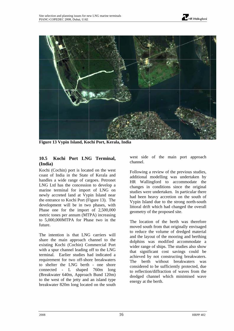
Figure 13 Vypin Island, Kochi Port, Kerala, India 10.5 Kochi Port LNG Terminal, (India) Kochi (Cochin) port is located on the west coast of India in the State of Kerala and handles a wide range of cargoes. Petronet LNG Ltd has the concession to develop a marine terminal for import of LNG on newly accreted land at Vypin Island near the entrance to Kochi Port (Figure 13). The development will be in two phases, with Phase one for the import of 2,500,000 metric tones per annum (MTPA) increasing to 5,000,000MTPA for Phase two in the future. The intention is that LNG carriers will share the main approach channel to the existing Kochi (Cochin) Commercial Port with a spur channel leading off to the LNG terminal. Earlier studies had indicated a requirement for two off-shore breakwaters to shelter the LNG berth - one shore connected - L shaped 760m long (Breakwater 640m, Approach Bund 120m) to the west of the jetty and an island type breakwater 820m long located on the south
west side of the main port approach channel. Following a review of the previous studies, additional modelling was undertaken by HR Wallingford to accommodate the changes in conditions since the original studies were undertaken. In particular there had been heavy accretion on the south of Vypin Island due to the strong north-south littoral drift which had changed the overall geometry of the proposed site. The location of the berth was therefore moved south from that originally envisaged to reduce the volume of dredged material and the layout of the mooring and berthing dolphins was modified accommodate a wider range of ships. The studies also show that significant cost savings could be achieved by not constructing breakwaters. The berth without breakwaters was considered to be sufficiently protected, due to reflection/diffraction of waves from the dredged channel which minimised wave energy at the berth.

Site selection and planning issues for new LNG marine terminals PIANC-COPEDEC 2008, Dubai, UAE
2008 17 HRPP 402
Figure 14 LNG Berth in operation
CONCLUSIONS The growth in demand for the transportation of LNG will generate the need for a significant number of new vessels and marine terminals to service this demand. LNG vessels typically require sheltered water depths of around 14 m at such terminals. These conditions are unlikely to occur naturally and a techno-economic study is required to determine the optimum location and layout for such facilities. Although a relatively small percentage of the overall cost of developing the complete storage and processing plant on shore, the optimisation of the marine terminal site at an early stage in the planning process can lead to significant savings, for example avoiding the entire cost of providing a breakwater. Costly overruns can occur if critical issues, like dredgability, rates of
siltation of channels, and coastal impacts are not addressed in the early stages. Terminal operations simulation can be used to optimise the level of berth protection required and the capacity of the storage tanks to be provided leading to potentially significant cost savings. New technology in offshore structures and LNG transfer is the key to the design of exposed terminals. This includes innovative breakwater design solutions and construction techniques, sophisticated fendering and interactive mooring systems and high response marine loading arms. Offshore storage using floating or submerged structures, LNG Single Point Moorings and sub-sea cryogenic pipelines are also examples of current research and development work being carried out to meet these challenges.

Site selection and planning issues for new LNG marine terminals PIANC-COPEDEC 2008, Dubai, UAE
2008 18 HRPP 402
USEFUL REFERENCES API RP2A LRFD, Recommended Practice for Planning, Designing and Constructing Fixed Offshore Platforms BSI (2000) “Maritime structures – Part 1: Code of practice for general criteria”, BS 6349-1, British Standard, BSI, ISBN 0-580-33169-5 BSI (1988) “Maritime structures – Part 2: Design of quay walls, jetties and dolphins”, BS 6349-2, British Standard Institute, BSI, ISBN 0-580-15898-5 BSI (1994) “Maritime structures – Part 4: Code of practice for design of fendering and mooring systems”, BS 6349-4, British Standard Institute, BSI, ISBN 0-580-22653-0 BSI (1994) “Maritime structures - Part 7: Guide to the Design and Construction of Breakwaters. Clarkson (2001) “The liquid gas carrier register”, Clarkson Research Studies, 2001 DETR (1999) “Port Marine Safety Code” EAU - Recommendations of the Committee for Waterfront Structures Harbours and Waterways, 1996, 7th English Edition, Ernst & Sohn, 2000 GSHAP (1999) “Global Seismic Hazard Assessment Programme” IMO (1995) “Recommendations on the Safe Transport of Dangerous Cargoes and Related Activities in Port Areas” IMO (1997) “ISM - International Safety Management - Code and Guidelines on Implementation”, International Maritime Organisation (IMO), London, 1997 International Safety Guide for Oil Tankers and Terminals (ISGOTT) (1996) OCIMF/ICS/IAPH, ISBN 1-85609-081-7 McGuire & White (2000) “Liquefied Gas Handling Principles on Ships and in Terminals”, 3rd Edition, SIGTTO Obras Maritimas Tecnologia, Direccion General de Puertos y Costas - Actions in the design of maritime and harbor works, ROM 0.2-90, Maritime Works Recommendations, 1990 Ocean Shipping Consultants (2004) World LNG to 2020 – Prospects for Trade and Shipping. OCIMF “Prediction of wind loads and current loads on VLCCs”. 2nd edition. Witherby & Co. Ltd, London, 1994. OCIMF/SIGTTO “Prediction of wind loads on large liquefied gas carriers”. Witherby & Co. Ltd, London, 1985. OCIMF (1997) “Mooring Equipment Guidelines”, Second Edition, ISBN 1-85609-088-4 OCIMF (1993) “Safety guide for terminals handling ships carrying liquefied gases in bulk” 2nd edition, ISBN –185609-057-4

Site selection and planning issues for new LNG marine terminals PIANC-COPEDEC 2008, Dubai, UAE
2008 19 HRPP 402
OECD (1996) “Guidance Concerning Chemical Safety in Port Areas”, Organisation for Economic Co-Operation and Development (OECD), Monograph No. 118, Paris, 1996 PIANC (1997) “Approach Channels – A Guide for Design”, International Navigation Association (PIANC), ISBN 2-87223-087-4 PIANC (2000) “Dangerous cargoes in ports”, Report of Working Group 35 PIANC (2001) “Seismic Design Guidelines for Port Structures” PIANC (2002) “Guidelines for the Design of Fender Systems”, ISBN 2-87223-125-0 SIGTTO (1992) “Guidelines for hazard analysis as an aid to management of safe operations” SIGTTO (1997a) “Site selection and Design for LNG Ports and Jetties”, Information Paper No. 14, Society of International Gas Tanker and Terminal Operators Ltd (SIGTTO), ISBN 1-85609-129-5 SIGTTO (1997b) “A listing of design guidelines for liquefied gas terminals (referencing ports and jetties)”, Information Paper No. 15 SIGTTO (1998) “Status of implementation of conventions, protocols and codes applicable to liquefied gas carriers”, Information Paper No. 1, Society of International Gas Tanker and Terminal Operators Ltd (SIGTTO), ISBN 1-85609-153-8 SIGTTO (2000) Liquefied Gas Handling Principles on Ships and in Terminals, McGuire and White, ISBN 1 85609 164 3 SIGTTO (2003) “LNG Operations in Port Areas”, ISBN 1-85607-256-9 Thoresen, C A (2003) “Port Designers Handbook - Recommendations and Guidelines”, ISBN 0727732285

HR Wallingford LtdHowbery ParkWallingfordOxfordshire OX10 8BAUK
tel +44 (0)1491 835381fax +44 (0)1491 832233email [email protected]
www.hrwallingford.co.uk
Fluid thinking…smart solutionsg y , pp
hydraulics, and in the management of
water and the water environment. Created as the Hydraulics Research
Station of the UK Government in 1947, the Company became a private
entity in 1982, and has since operated as a independent, non profi t
distributing fi rm committed to building knowledge and solving problems,
expertly and appropriately.
Today, HR Wallingford has a 50 year track record of achievement in applied
research and consultancy, and a unique mix of know-how, assets and
facilities, including state of the art physical modelling laboratories, a full
range of computational modelling tools, and above all, expert staff with
world-renowned skills and experience.
The Company has a pedigree of excellence and a tradition of innovation,
which it sustains by re-investing profi ts from operations into programmes of
strategic research and development designed to keep it – and its clients and
partners – at the leading edge.
Headquartered in the UK, HR Wallingford reaches clients and partners
globally through a network of offi ces, agents and alliances around the
world.