hpstm products series a900 piezo / micropirani vacuum sensor
TRANSCRIPT

HPSTM ProductsSeries A900
Piezo / MicroPiraniTM
Vacuum Sensor System
Vacuum TransducersPiezo
Piezo+PiezoSteelTM
PiezoSteel+TM
MicroPiraniTM
DualTransTM
DualTrans+TM
OPERATING ANDMAINTENANCE MANUAL

Please Note:MKS Instruments provides these documents as the latest version for the revision indicated.The material is subject to change without notice, and should be verified if used in a criticalapplication.

HPSTM ProductsSeries A900
Piezo / MicroPiraniTM
Vacuum Sensor System
Vacuum TransducersPiezo
Piezo+PiezoSteelTM
PiezoSteel+TM
MicroPiraniTM
DualTransTM
DualTrans+TM
OPERATING ANDMAINTENANCE MANUAL
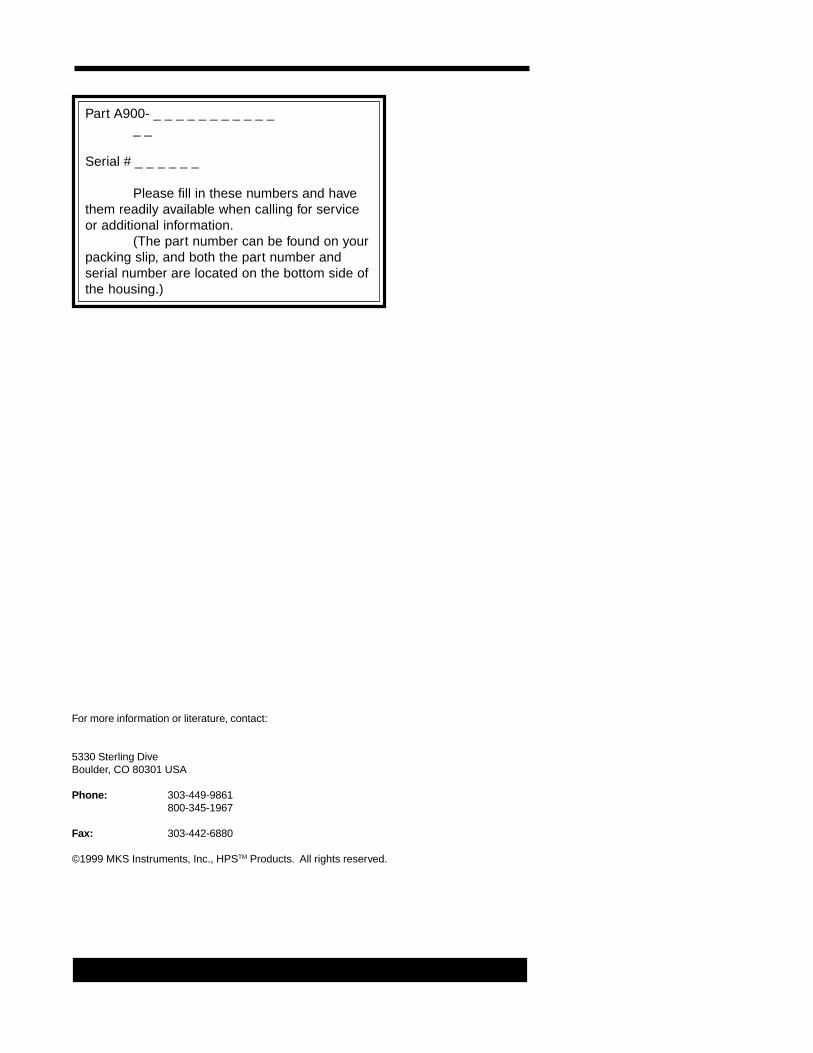
Part A900- _ _ _ _ _ _ _ _ _ _ __ _
Serial # _ _ _ _ _ _
Please fill in these numbers and havethem readily available when calling for serviceor additional information.
(The part number can be found on yourpacking slip, and both the part number andserial number are located on the bottom side ofthe housing.)
For more information or literature, contact:
5330 Sterling DiveBoulder, CO 80301 USA
Phone: 303-449-9861800-345-1967
Fax: 303-442-6880
©1999 MKS Instruments, Inc., HPSTM Products. All rights reserved.
Table of Contents
Package Contents ..................................................................... 1
Unpacking ............................................................................................... 1General safety information ............................................................................................ 1
Symbols Used in this Manual .................................................... 2
Safety Precautions .................................................................... 3
A900 features ............................................................................ 4
Instrument installation ................................................................................................... 4Transducer installation .................................................................................................. 4Operation voltage .......................................................................................................... 5
Front panel ............................................................................................. 5Menu use ....................................................................................................................... 6LED display ................................................................................................................... 6
Rear panel .............................................................................................. 7Transducer connectors ...........................................................................................7Power switch ...........................................................................................................7Main voltage ...........................................................................................................7Serial label ..............................................................................................................7Analog out & Remote Zero connector ....................................................................7Setpoint relay connector .........................................................................................7Turning the instrument on .......................................................................................8
Setpoint menu .............................................................................................................. 8Edit setpoint low value ...........................................................................................8Edit setpoint high value ..........................................................................................9Setpoint relay ..........................................................................................................9Edit setpoint relay setting .......................................................................................9
Lock instrument menu ................................................................................................... 9Lock procedure .......................................................................................................9Unlock procedure ................................................................................................. 10
Transducer Selection menu ........................................................................................ 10View transducer selection .................................................................................... 10Change transducer selection ................................................................................10
Gas Selection menu .................................................................................................... 10View gas selection ................................................................................................ 10Change gas selection ........................................................................................... 10
Adjustment menu ....................................................................................................... 11Zero and span ...................................................................................................... 11Reset and User adjustment .................................................................................. 11Pirani zero adjustment - ......................................................................................11Pirani remote zero adjustment - ........................................................................... 12Piezo zero adjustment - ........................................................................................ 13Piezo Auto Zero adjustment - ............................................................................... 13Pirani span adjustment - ....................................................................................... 13Piezo span adjustment - ......................................................................................13
Linkpoint menu ............................................................................................................ 14
Table of Contents
View link selection ................................................................................................ 14Change link selection ........................................................................................... 14Change linkpoint value .........................................................................................14
Display unit menu ....................................................................................................... 14View display unit selection ...................................................................................14Change display unit .............................................................................................. 14
Vacuum transducers ................................................................................................... 15Piezo transducer ..................................................................................................15Piezo+ transducer ................................................................................................ 15PiezoSteelTM transducer ....................................................................................... 16PiezoSteel+TM transducer ..................................................................................... 16MicroPiraniTM transducer ......................................................................................16DualTransTM transducer ........................................................................................ 16DualTrans+™ transducer ......................................................................................16Transducer media compatibility ............................................................................ 16Outgassing .......................................................................................................... 17Explosive environments ....................................................................................... 17MicroPiraniTM voltage to pressure conversion - .................................................... 17Measuring range limits .........................................................................................18Transducer dimensions, DN16KF vacuum connection .........................................18
Dimensions ................................................................................................................. 19Specifications .............................................................................................................. 19Changing fuse ............................................................................................................. 20 Connectors ................................................................................................................ 20Transducer extension cables ...................................................................................... 20Pressure units ............................................................................................................. 21
Warranty .................................................................................. 22
Notes ....................................................................................... 23
������ ������ ������������ ������ ������������ ������ ������������ ������ ������������ ������ �������TM � ������� ������� ������� ������� ������
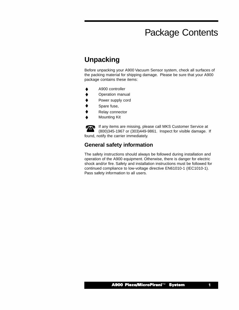
UnpackingBefore unpacking your A900 Vacuum Sensor system, check all surfaces ofthe packing material for shipping damage. Please be sure that your A900package contains these items:
A900 controllerOperation manual
Power supply cord
Spare fuse,
Relay connectorMounting Kit
If any items are missing, please call MKS Customer Service at(800)345-1967 or (303)449-9861. Inspect for visible damage. If
found, notify the carrier immediately.
General safety information
The safety instructions should always be followed during installation andoperation of the A900 equipment. Otherwise, there is danger for electricshock and/or fire. Safety and installation instructions must be followed forcontinued compliance to low-voltage directive EN61010-1 (IEC1010-1).Pass safety information to all users.
Package Contents
� ����� ������ ������������ ������ ������������ ������ ������������ ������ ������������ ������ �������TM� ������� ������� ������� ������� ������
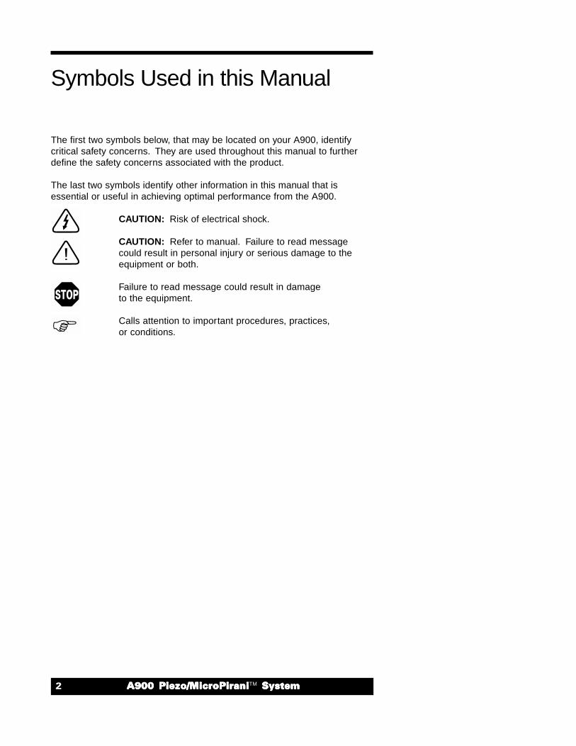
The first two symbols below, that may be located on your A900, identifycritical safety concerns. They are used throughout this manual to furtherdefine the safety concerns associated with the product.
The last two symbols identify other information in this manual that isessential or useful in achieving optimal performance from the A900.
CAUTION: Risk of electrical shock.
CAUTION: Refer to manual. Failure to read messagecould result in personal injury or serious damage to theequipment or both.
Failure to read message could result in damageto the equipment.
Calls attention to important procedures, practices,or conditions.
Symbols Used in this Manual
������ ������ ������������ ������ ������������ ������ ������������ ������ ������������ ������ �������TM � ������� ������� ������� ������� ������
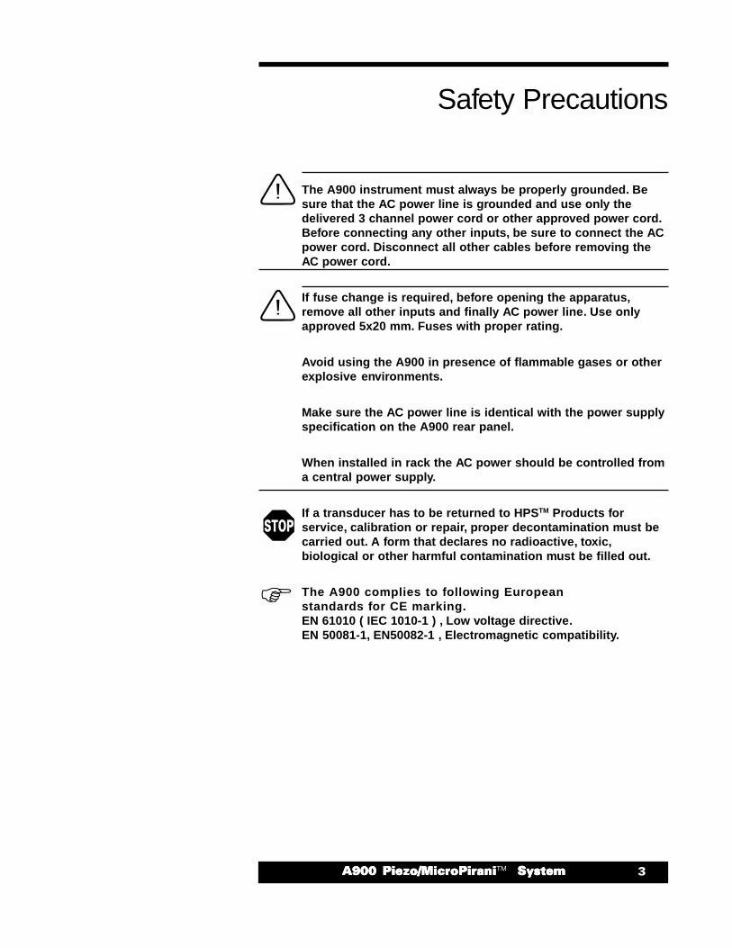
The A900 instrument must always be properly grounded. Besure that the AC power line is grounded and use only thedelivered 3 channel power cord or other approved power cord.Before connecting any other inputs, be sure to connect the ACpower cord. Disconnect all other cables before removing theAC power cord.
If fuse change is required, before opening the apparatus,remove all other inputs and finally AC power line. Use onlyapproved 5x20 mm. Fuses with proper rating.
Avoid using the A900 in presence of flammable gases or otherexplosive environments.
Make sure the AC power line is identical with the power supplyspecification on the A900 rear panel.
When installed in rack the AC power should be controlled froma central power supply.
If a transducer has to be returned to HPSTM Products forservice, calibration or repair, proper decontamination must becarried out. A form that declares no radioactive, toxic,biological or other harmful contamination must be filled out.
The A900 complies to following Europeanstandards for CE marking.EN 61010 ( IEC 1010-1 ) , Low voltage directive.EN 50081-1, EN50082-1 , Electromagnetic compatibility.
Safety Precautions
� ����� ������ ������������ ������ ������������ ������ ������������ ������ ������������ ������ �������TM� ������� ������� ������� ������� ������
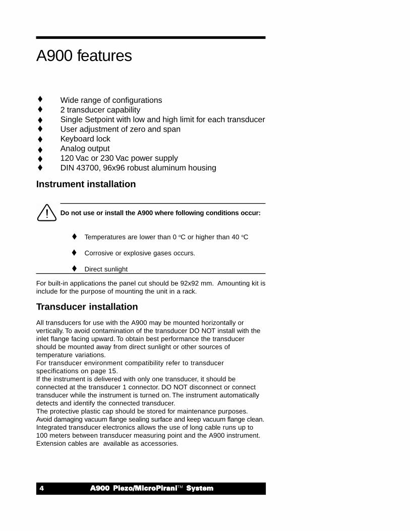
Wide range of configurations2 transducer capabilitySingle Setpoint with low and high limit for each transducerUser adjustment of zero and spanKeyboard lockAnalog output120 Vac or 230 Vac power supplyDIN 43700, 96x96 robust aluminum housing
Instrument installation
Do not use or install the A900 where following conditions occur:
Temperatures are lower than 0 oC or higher than 40 oC
Corrosive or explosive gases occurs.
Direct sunlight
For built-in applications the panel cut should be 92x92 mm. Amounting kit isinclude for the purpose of mounting the unit in a rack.
Transducer installation
All transducers for use with the A900 may be mounted horizontally orvertically. To avoid contamination of the transducer DO NOT install with theinlet flange facing upward. To obtain best performance the transducershould be mounted away from direct sunlight or other sources oftemperature variations.For transducer environment compatibility refer to transducerspecifications on page 15.If the instrument is delivered with only one transducer, it should beconnected at the transducer 1 connector. DO NOT disconnect or connecttransducer while the instrument is turned on. The instrument automaticallydetects and identify the connected transducer.The protective plastic cap should be stored for maintenance purposes.Avoid damaging vacuum flange sealing surface and keep vacuum flange clean.Integrated transducer electronics allows the use of long cable runs up to100 meters between transducer measuring point and the A900 instrument.Extension cables are available as accessories.
A900 features
������ ������ ������������ ������ ������������ ������ ������������ ������ ������������ ������ �������TM � ������� ������� ������� ������� ������
Operation voltage
The serial label is specifies the AC power supply required. Theinstrument is delivered for 120 VAC or 230 VAC use. Make surethat the available AC supply voltage is identical with the powersupply voltage on the serial label.
If the instrument is powered from AC voltage other than indicated, it’snecessary to make an internal modification. Change of power supply setupshould only be performed by qualified electrical or electronics maintenancepersonal. For power supply setup procedure contact HPSTM Products. Onlyuse the delivered 3 wire power cord or other approved power cord. TheA900 power cord must always be properly grounded.
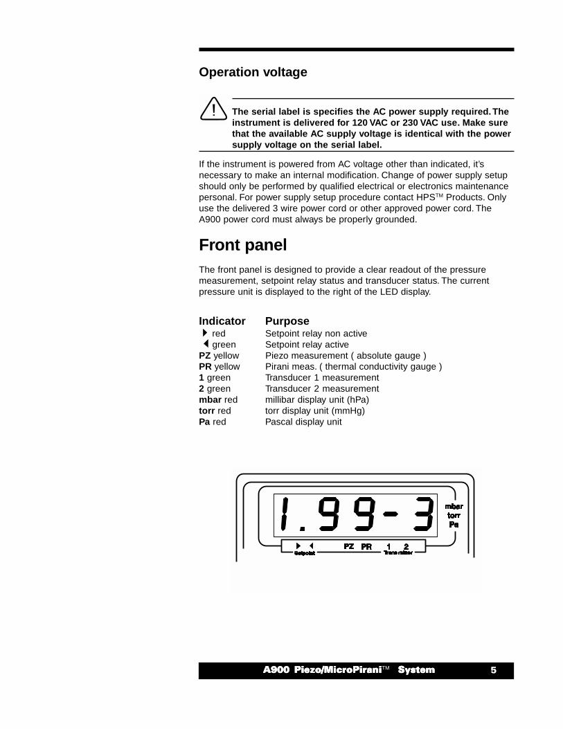
Front panelThe front panel is designed to provide a clear readout of the pressuremeasurement, setpoint relay status and transducer status. The currentpressure unit is displayed to the right of the LED display.
Indicator Purpose red Setpoint relay non active green Setpoint relay activePZ yellow Piezo measurement ( absolute gauge )PR yellow Pirani meas. ( thermal conductivity gauge )1 green Transducer 1 measurement2 green Transducer 2 measurementmbar red millibar display unit (hPa)torr red torr display unit (mmHg)Pa red Pascal display unit
� ����� ������ ������������ ������ ������������ ������ ������������ ������ ������������ ������ �������TM� ������� ������� ������� ������� ������
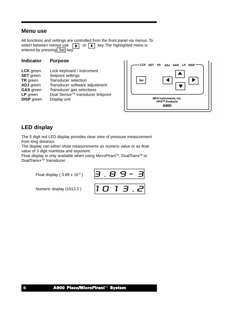
Menu use
All functions and settings are controlled from the front panel via menus. Toselect between menus use or key. The highlighted menu isentered by pressing Set key.
Indicator Purpose
LCK green Lock keyboard / instrumentSET green Setpoint settingsTR green Transducer selectionADJ green Transducer software adjustmentGAS green Transducer gas selectionsLP green Dual SensorTM transducer linkpointDISP green Display unit
LED display
The 5 digit red LED display provides clear view of pressure measurementfrom long distance.The display can either show measurements as numeric value or as floatvalue of 3 digit mantissa and exponent.Float display is only available when using MicroPiraniTM, DualTransTM orDualTrans+TM transducer.
Float display ( 3.89 x 10⁻³ )
Numeric display (1013.2 )
������ ������ ������������ ������ ������������ ������ ������������ ������ ������������ ������ �������TM � ������� ������� ������� ������� ������
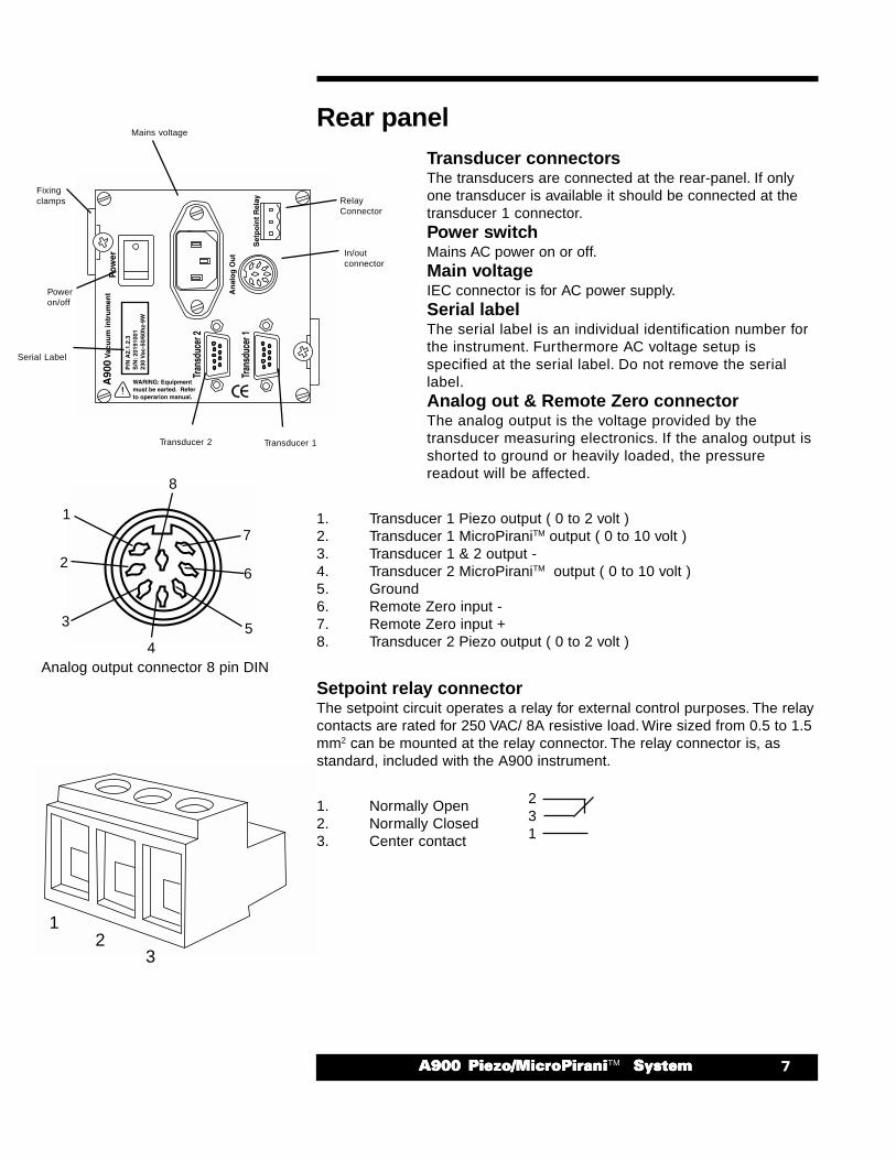
Rear panelTransducer connectorsThe transducers are connected at the rear-panel. If onlyone transducer is available it should be connected at thetransducer 1 connector.Power switchMains AC power on or off.Main voltageIEC connector is for AC power supply.Serial labelThe serial label is an individual identification number forthe instrument. Furthermore AC voltage setup isspecified at the serial label. Do not remove the seriallabel.Analog out & Remote Zero connectorThe analog output is the voltage provided by thetransducer measuring electronics. If the analog output isshorted to ground or heavily loaded, the pressurereadout will be affected.
1. Transducer 1 Piezo output ( 0 to 2 volt )2. Transducer 1 MicroPiraniTM output ( 0 to 10 volt )3. Transducer 1 & 2 output -4. Transducer 2 MicroPiraniTM output ( 0 to 10 volt )5. Ground6. Remote Zero input -7. Remote Zero input +8. Transducer 2 Piezo output ( 0 to 2 volt )
Setpoint relay connectorThe setpoint circuit operates a relay for external control purposes. The relaycontacts are rated for 250 VAC/ 8A resistive load. Wire sized from 0.5 to 1.5mm2 can be mounted at the relay connector. The relay connector is, asstandard, included with the A900 instrument.
1. Normally Open2. Normally Closed3. Center contact
Mains voltage
RelayConnector
In/outconnector
Transducer 1Transducer 2
Serial Label
Poweron/off
Fixingclamps
231
12
3
Analog output connector 8 pin DIN
1
2
3
45
6
7
8
� ����� ������ ������������ ������ ������������ ������ ������������ ������ ������������ ������ �������TM� ������� ������� ������� ������� ������
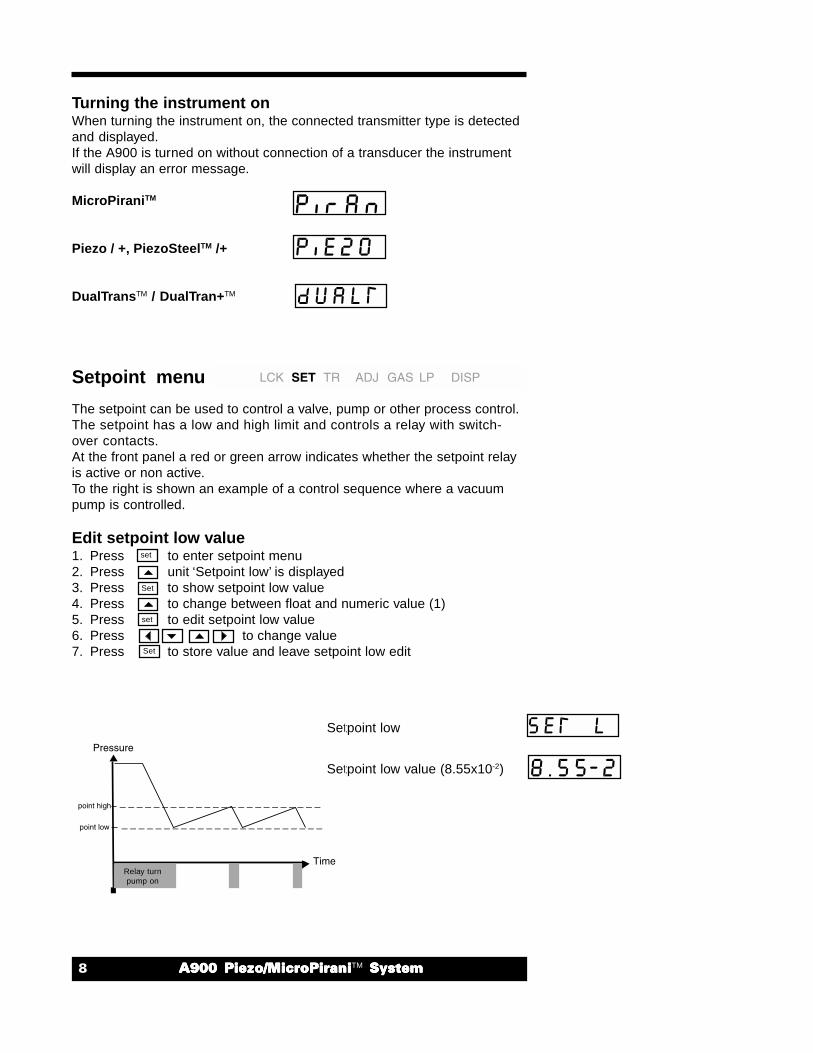
Turning the instrument onWhen turning the instrument on, the connected transmitter type is detectedand displayed.If the A900 is turned on without connection of a transducer the instrumentwill display an error message.
MicroPiraniTM
Piezo / +, PiezoSteelTM /+
DualTransTM / DualTran+TM
Setpoint menu
The setpoint can be used to control a valve, pump or other process control.The setpoint has a low and high limit and controls a relay with switch-over contacts.At the front panel a red or green arrow indicates whether the setpoint relayis active or non active.To the right is shown an example of a control sequence where a vacuumpump is controlled.
Edit setpoint low value1. Press to enter setpoint menu2. Press unit ‘Setpoint low’ is displayed3. Press to show setpoint low value4. Press to change between float and numeric value (1)5. Press to edit setpoint low value6. Press to change value7. Press to store value and leave setpoint low edit
Set
set
set
Set
Setpoint low
Setpoint low value (8.55x10⁻²)
_ _ _ _ _ _ _ _ _ _ _ _ _ _ _ _ _ _ _ _ _ _ _ _
_ _ _ _ _ _ _ _ _ _ _ _ _ _ _ _ _ _ _ _ _ _ _ _
Relay turnpump on
������ ������ ������������ ������ ������������ ������ ������������ ������ ������������ ������ �������TM � ������� ������� ������� ������� ������
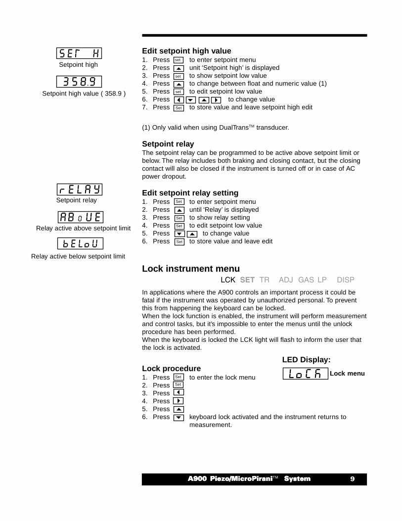
Edit setpoint high value1. Press to enter setpoint menu2. Press unit ‘Setpoint high’ is displayed3. Press to show setpoint low value4. Press to change between float and numeric value (1)5. Press to edit setpoint low value6. Press to change value7. Press to store value and leave setpoint high edit
(1) Only valid when using DualTransTM transducer.
Setpoint relayThe setpoint relay can be programmed to be active above setpoint limit orbelow. The relay includes both braking and closing contact, but the closingcontact will also be closed if the instrument is turned off or in case of ACpower dropout.
Edit setpoint relay setting1. Press to enter setpoint menu2. Press until ‘Relay’ is displayed3. Press to show relay setting4. Press to edit setpoint low value5. Press to change value6. Press to store value and leave edit
Lock instrument menu
In applications where the A900 controls an important process it could befatal if the instrument was operated by unauthorized personal. To preventthis from happening the keyboard can be locked.When the lock function is enabled, the instrument will perform measurementand control tasks, but it’s impossible to enter the menus until the unlockprocedure has been performed.When the keyboard is locked the LCK light will flash to inform the user thatthe lock is activated.
Lock procedure1. Press to enter the lock menu2. Press3. Press4. Press5. Press6. Press keyboard lock activated and the instrument returns to
measurement.
set
set
set
Set
Set
Set
Set
Set
Set
Setpoint high
Relay active above setpoint limit
Lock menu
Setpoint high value ( 358.9 )
Relay active below setpoint limit
Set
LED Display:
Setpoint relay

�� ����� ������ ������������ ������ ������������ ������ ������������ ������ ������������ ������ �������TM� ������� ������� ������� ������� ������
Unlock procedure1. Press to enter the lock menu2. Press3. Press4. Press5. Press to unlock the instrument6. Press to return to measurement
Transducer Selection menu
Two transducers can be connected to the instrument. The transducerto be used is selected in the transducer selection menu. Thetransducer selection menu is only accessible when two transducersare connected to the instrument.If user adjustment of zero and span has been performed, data is stored foreach transducer.
View transducer selection1. Press to view current transducer selection.2. Press to return to measurement.
Change transducer selectionPress to change current transducer selection.Press or to change between transducer 1 and 2.Press to select display transducer
Gas Selection menu
The gas selection menu can only be accessed when using MicroPiraniTM,DualTransTM or DualTrans+TM transducer. These transducers usesmeasurement of thermal conductivity and consequently the readout will dependon gas or gas concentration. The A900 is calibrated for use with severalcommon gases like atmospheric air, nitrogen, helium, argon and hydrogen.The gas selection menu allows the user to specify the measuring gas.
View gas selectionPress to view current gas selection.Press to return to measurement.
Change gas selectionPress and simultaneously to change gas selection.Press or to change between different gases.Press to select displayed gas.
LED Displays:
Unlock confirmation
Set
Set
Set
Transducer 2
Transducer 1
Set
Set
Set
Set
set
Argon gas
Hydrogen gas
Helium gas
Nitrogen gas
Atmospheric air
������� ������ ������������ ������ ������������ ������ ������������ ������ ������������ ������ �������TM � ������� ������� ������� ������� ������
Adjustment menu
All HPSTM A900 transducers are factory adjusted and recognized forexcellent stability. However, the adjustment menu allows the user to makesoftware adjustment of zero and span to compensate for minor drift.When using two transducers with the instrument each transducer mustbe adjusted, because data is stored for each transducer. All adjustmentdata are stored in permanent memory, and thereby not affected whenpower is turned off.
Zero and spanThe zero point adjustment is an offset of the full measuring span. The spanadjustment sets the full scale output at atmospheric pressure.If both zero adjustment and a span adjustment is required the zeroadjustment must be performed before making the span adjustment.
Reset and User adjustmentTwo types of adjustments can be selected, the zero adjustment as well asthe span adjustment. The reset adjustment is a general setup, that can beused if the user adjustment has been adjusted improperly.
The user adjustment allows the instrumentation software to compensate forminor differences of transducer zero and span.If a new transducer is connected to the instrument, reset adjustment shouldbe selected or for obtaining best performance the user adjustmentprocedure should be followed.
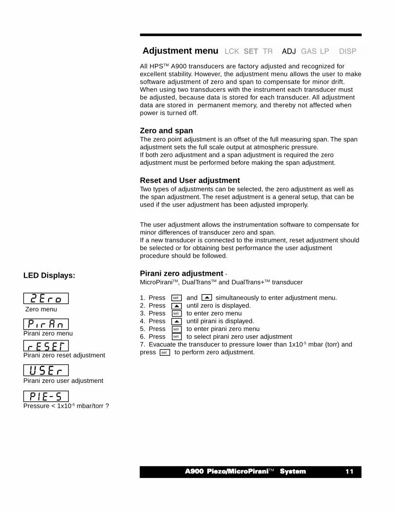
Pirani zero adjustment -MicroPiraniTM, DualTransTM and DualTrans+TM transducer
1. Press and simultaneously to enter adjustment menu.2. Press until zero is displayed.3. Press to enter zero menu4. Press until pirani is displayed.5. Press to enter pirani zero menu6. Press to select pirani zero user adjustment7. Evacuate the transducer to pressure lower than 1x10⁻⁵ mbar (torr) andpress to perform zero adjustment.
set
set
set
set
set
Pressure < 1x10⁻⁵ mbar/torr ?
LED Displays:
Zero menu
Pirani zero menu
Pirani zero reset adjustment
Pirani zero user adjustment

�� ����� ������ ������������ ������ ������������ ������ ������������ ������ ������������ ������ �������TM� ������� ������� ������� ������� ������
Pirani remote zero adjustment -MicroPiraniTM, DualTransTM and DualTrans+TM transducer
The Remote Zero feature allows automatically zero adjustment of thepirani from an external source. This feature can be used in applicationswhere another high or ultra high vacuum instruments like cold cathode,ionization, mass spectrometer or any other instrument able to measure apressure lower than 1x10⁻⁵ mbar (torr) is available. To use the RemoteZero function a setpoint with external relay must be available at the highvacuum instrument.
The Remote Zero input is available at the analog output connector at therear panel ( refer to page 4 & 5 )
Connect the A900 Remote Zero input to HV (High Vacuum)instrument relay contact.
Program the HV instrument to close relay contact at pressure below8x10-6 mbar (torr).
The A900 instrument will now be automatically zero adjusted by external HVinstrument, whenever pressure is lower than 8x10⁻⁶ mbar.The instrument does not store zero adjustment made by the Remote Zerofunction. When the instrument is turned off the zero adjustment is lost, andwhen the instrument is turned on again it will use reset or user adjustment.
Piezo zero adjustment -Piezo, Piezo+, PiezoSteelTM, PiezoSteel+TM, DualTransTM and DualTrans+TM
transducer
1. Press and simultaneously to enter adjustment menu.2. Press until zero is displayed.3. Press to enter zero menu4. Press until piezo is displayed.5. Press to enter piezo zero menu6. Press to select piezo zero user adjustment7. Evacuate the transducer to pressure lower than 0.1 mbar (torr) and press to perform zero adjustment.
set
set
set
set
set
Pressure < 0.1 mbar/torr
LED Displays:
Zero menu
Piezo zero reset adjustment
Piezo zero auto adjustment
Piezo zero user adjustment
Piezo zero menu
������� ������ ������������ ������ ������������ ������ ������������ ������ ������������ ������ �������TM � ������� ������� ������� ������� ������
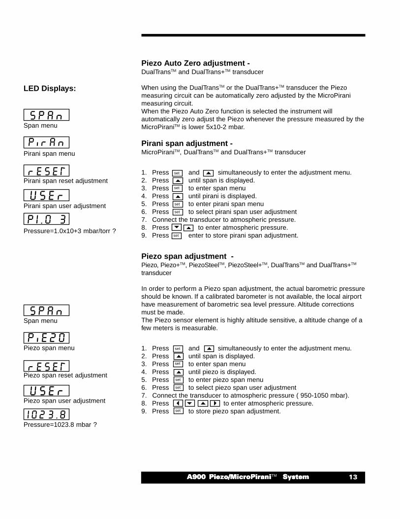
Piezo Auto Zero adjustment -DualTransTM and DualTrans+TM transducer
When using the DualTransTM or the DualTrans+TM transducer the Piezomeasuring circuit can be automatically zero adjusted by the MicroPiranimeasuring circuit.When the Piezo Auto Zero function is selected the instrument willautomatically zero adjust the Piezo whenever the pressure measured by theMicroPiraniTM is lower 5x10⁻² mbar.
Pirani span adjustment -MicroPiraniTM, DualTransTM and DualTrans+TM transducer
1. Press and simultaneously to enter the adjustment menu.2. Press until span is displayed.3. Press to enter span menu4. Press until pirani is displayed.5. Press to enter pirani span menu6. Press to select pirani span user adjustment7. Connect the transducer to atmospheric pressure.8. Press to enter atmospheric pressure.9. Press enter to store pirani span adjustment.
Piezo span adjustment -Piezo, Piezo+TM, PiezoSteelTM, PiezoSteel+TM, DualTransTM and DualTrans+TM
transducer
In order to perform a Piezo span adjustment, the actual barometric pressureshould be known. If a calibrated barometer is not available, the local airporthave measurement of barometric sea level pressure. Altitude correctionsmust be made.The Piezo sensor element is highly altitude sensitive, a altitude change of afew meters is measurable.
1. Press and simultaneously to enter the adjustment menu.2. Press until span is displayed.3. Press to enter span menu4. Press until piezo is displayed.5. Press to enter piezo span menu6. Press to select piezo span user adjustment7. Connect the transducer to atmospheric pressure ( 950-1050 mbar).8. Press to enter atmospheric pressure.9. Press to store piezo span adjustment.
Pressure=1.0x10+3 mbar/torr ?
LED Displays:
set
set
set
set
set
set
set
set
set
set
Span menu
Pirani span menu
Pirani span reset adjustment
Pirani span user adjustment
Span menu
Piezo span menu
Piezo span reset adjustment
Piezo span user adjustment
Pressure=1023.8 mbar ?
�� ����� ������ ������������ ������ ������������ ������ ������������ ������ ������������ ������ �������TM� ������� ������� ������� ������� ������
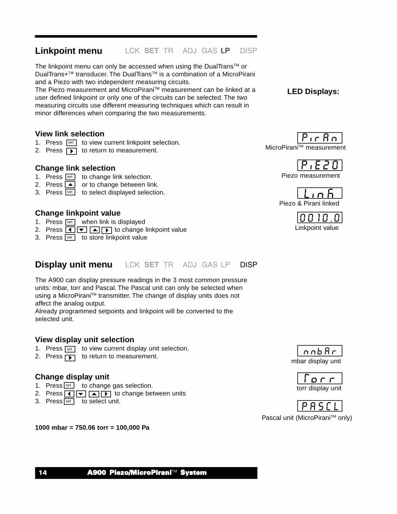
Linkpoint menu
The linkpoint menu can only be accessed when using the DualTransTM orDualTrans+TM transducer. The DualTransTM is a combination of a MicroPiraniand a Piezo with two independent measuring circuits.The Piezo measurement and MicroPiraniTM measurement can be linked at auser defined linkpoint or only one of the circuits can be selected. The twomeasuring circuits use different measuring techniques which can result inminor differences when comparing the two measurements.
View link selection1. Press to view current linkpoint selection.2. Press to return to measurement.
Change link selection1. Press to change link selection.2. Press or to change between link.3. Press to select displayed selection.
Change linkpoint value1. Press when link is displayed2. Press to change linkpoint value3. Press to store linkpoint value
Display unit menu
The A900 can display pressure readings in the 3 most common pressureunits: mbar, torr and Pascal. The Pascal unit can only be selected whenusing a MicroPiraniTM transmitter. The change of display units does notaffect the analog output.Already programmed setpoints and linkpoint will be converted to theselected unit.
View display unit selection1. Press to view current display unit selection.2. Press to return to measurement.
Change display unit1. Press to change gas selection.2. Press to change between units3. Press to select unit.
Linkpoint value
Pascal unit (MicroPiraniTM only)
1000 mbar = 750.06 torr = 100,000 Pa
set
set
set
set
set
set
set
LED Displays:
MicroPiraniTM measurement
Piezo measurement
Piezo & Pirani linked
mbar display unit
torr display unit
set
������� ������ ������������ ������ ������������ ������ ������������ ������ ������������ ������ �������TM � ������� ������� ������� ������� ������
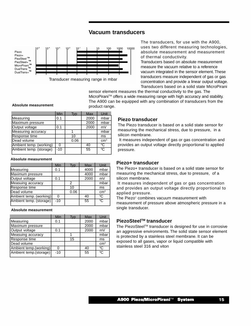
Min Typ Max UnitMeasuring 0.1 4000 mbarMaximum pressure 4000 mbarOutput voltage 0.1 2000 mVMeasuing accuracy 2 mbarResponse time 10 msDead volume 0.06 cm3
Ambient temp. (working) 0 40 0CAmbient temp. (storage) -10 55 0C
Vacuum transducers
The transducers, for use with the A900,uses two different measuring technologies,absolute measurement and measurementof thermal conductivity.Transducers based on absolute measurementmeasure the vacuum relative to a referencevacuum integrated in the sensor element. Thesetransducers measure independent of gas or gasconcentration and provide a linear output voltage.Transducers based on a solid state MicroPirani
sensor element measures the thermal conductivity to the gas. TheMicroPiraniTM offers a wide measuring range with high accuracy and stability.The A900 can be equipped with any combination of transducers from theproduct range.
Piezo transducerThe Piezo transducer is based on a solid state sensor formeasuring the mechanical stress, due to pressure, in asilicon membrane. It measures independent of gas or gas concentration andprovides an output voltage directly proportional to appliedpressure.
Piezo+ transducerThe Piezo+ transducer is based on a solid state sensor formeasuring the mechanical stress, due to pressure, of asilicon membrane. It measures independent of gas or gas concentrationand provides an output voltage directly proportional toapplied pressure.The Piezo+ combines vacuum measurement withmeasurement of pressure above atmospheric pressure in asingle transducer.
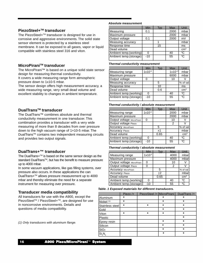
PiezoSteelTM transducerThe PiezoSteelTM transducer is designed for use in corrosivean aggressive environments. The solid state sensor elementis protected by a stainless steel membrane. It can beexposed to all gases, vapor or liquid compatible withstainless steel 316 and viton
Min Typ Max UnitMeasuring 0.1 2000 mbarMaximum pressure 2000 mbarOutput voltage 0.1 2000 mVMeasuing accuracy 1 mbarResponse time 15 msDead volume cm3
Ambient temp.(working) 0 40 0CAmbient temp.(storage) -10 55 0C
Min Typ Max UnitMeasuring 0.1 2000 mbarMaximum pressure 2000 mbarOutput voltage 0.1 2000 mVMeasuring accuracy 1 mbarResponse time 10 msDead volume 0.06 cm3
Ambient temp. (working) 0 40 0CAmbient temp. (storage) -10 55 0C
Transducer measuring range in mbar
Absolute measurement
Absolute measurement
Absolute measurement
�� ����� ������ ������������ ������ ������������ ������ ������������ ������ ������������ ������ �������TM� ������� ������� ������� ������� ������
PiezoSteel+TM transducerThe PiezoSteel+TM transducer is designed for use incorrosive and aggressive environments. The solid statesensor element is protected by a stainless steelmembrane. It can be exposed to all gases, vapor or liquidcompatible with stainless steel 316 and viton.
MicroPiraniTM transducerThe MicroPirani™ is based on a unique solid state sensordesign for measuring thermal conductivity.It covers a wide measuring range form atmosphericpressure down to 1x10⁻⁵ mbar.The sensor design offers high measurement accuracy, awide measuring range, very small dead volume andexcellent stability to changes in ambient temperature.
DualTransTM transducerThe DualTrans™ combines absolute and thermalconductivity measurement in one transducer. Thiscombination provides a transducer with a very widemeasuring of more than 8 decades from over pressuredown to the high vacuum range of 1×10⁻⁵ mbar. TheDualTransTM contains two independent measuring circuitsand provides two output signals.
DualTrans+™ transducerThe DualTrans+TM is based on the same sensor design as thestandard DualTransTM, but has the benefit to measure pressureup to 4000 mbar.In some vacuum applications, like gas filling systems, overpressure also occurs. In these applications the canDualTrans+TM allows pressure measurement up to 4000mbar and thereby eliminate the need for a separateinstrument for measuring over pressure.
Transducer media compatibilityAll transducers for use with the A900, except thePiezoSteelTM / PiezoSteel+TM, are designed for usein noncorrosive environments. Details andquestions of media compatibility.
Min Typ Max UnitMeasuring 0.1 2000 mbarMaximum pressure 2000 mbarOutput voltage 0.1 2000 mVMeasuing accuracy 1 mbarResponse time 15 msDead volume cm3
Ambient temp.(working) 0 40 0CAmbient temp.(storage) -10 55 0C
Min Typ Max UnitMeasuring range 1x10⁻⁵ 1x10+3 mbarMaximum pressure 6000 mbarOutput voltage 0 10 VMeasuing accuracy 5 % of valResponse time 10 msDead volume 0.6 cm3
Ambient temp.(working) 0 40 0CAmbient temp.(storage) -10 55 0C
Absolute measurement
Thermal conductivity measurement
Thermal conductivity / absolute measurement
Thermal conductivity / absolute measurement
Table. 1 Exposed materials for different transducers.
(1) Only transducers with aluminum flange.
Piezo /+ PiezoSteel /+ MicroPirani DualTrans /+Aluminum * * *Nickel (1) * * *Stainless steel * * * *Gold * *Viton * * * *Plastic *Epoxy resin * *Silicon * *SiO2 * *Si3N4 * *
Min Typ Max UnitMeasuring range 1x10⁻⁵ 4000 mbarMaximum pressure 4000 mbarOutput voltage MicroPirani 0 10 VOutput voltage Piezo 0 2 VAccuracy MicroPirani 5 % of val
Accuracy Piezo +2 mbarDead volume 0.65 cm3
Ambient temp.(working) 0 40 0CAmbient temp.(storage) -10 55 0C
Min Typ Max UnitMeasuring range 1x10⁻⁵ 2000 mbarMaximum pressure 2000 mbarOutput voltage MicroPirani 0 10 VOutput voltage Piezo 2 VAccuracy MicroPirani 5 % of valAccuracy Piezo +1 mbarDead volume 0.65 cm3
Ambient temp.(working) 0 40 0CAmbient temp.(storage) -10 55 0C
������� ������ ������������ ������ ������������ ������ ������������ ������ ������������ ������ �������TM � ������� ������� ������� ������� ������
OutgassingThe use of solid state micro sensor technology exposes only a smallamount of sensor material to the vacuum, thereby reducing the outgassingrate. Furthermore, the internal volume, commonly referred as dead volume,is significantly smaller compared to competitive gauges.
Explosive environments WARNINGSpecial precautions must be taken if any of the A900 transducers are usedin applications where explosive gases are present. Contact HPSTM Productsfor instructions of use in these applications.
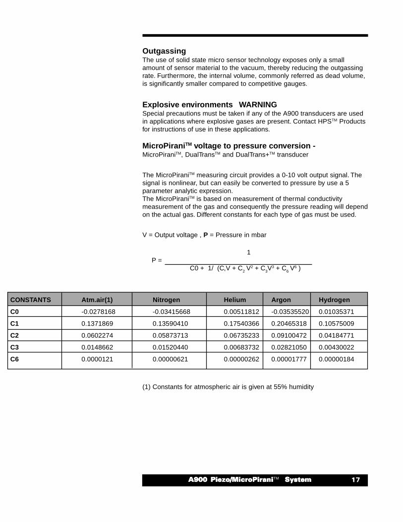
MicroPiraniTM voltage to pressure conversion -MicroPiraniTM, DualTransTM and DualTrans+TM transducer
The MicroPiraniTM measuring circuit provides a 0-10 volt output signal. Thesignal is nonlinear, but can easily be converted to pressure by use a 5parameter analytic expression.The MicroPiraniTM is based on measurement of thermal conductivitymeasurement of the gas and consequently the pressure reading will dependon the actual gas. Different constants for each type of gas must be used.
V = Output voltage , P = Pressure in mbar
1 P =
C0 + 1/ (C,V + C2 V2 + C
3V3 + C
6 V6 )
(1) Constants for atmospheric air is given at 55% humidity
CONSTANTS Atm.air(1) Nitrogen Helium Argon Hydrogen
C0 -0.0278168 -0.03415668 0.00511812 -0.03535520 0.01035371
C1 0.1371869 0.13590410 0.17540366 0.20465318 0.10575009
C2 0.0602274 0.05873713 0.06735233 0.09100472 0.04184771
C3 0.0148662 0.01520440 0.00683732 0.02821050 0.00430022
C6 0.0000121 0.00000621 0.00000262 0.00001777 0.00000184
�� ����� ������ ������������ ������ ������������ ������ ������������ ������ ������������ ������ �������TM� ������� ������� ������� ������� ������
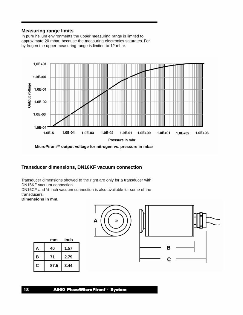
Measuring range limitsIn pure helium environments the upper measuring range is limited toapproximate 20 mbar, because the measuring electronics saturates. Forhydrogen the upper measuring range is limited to 12 mbar.
Transducer dimensions, DN16KF vacuum connection
Transducer dimensions showed to the right are only for a transducer withDN16KF vacuum connection.DN16CF and ½ inch vacuum connection is also available for some of thetransducers.Dimensions in mm.
MicroPiraniTM output voltage for nitrogen vs. pressure in mbar
mm inch
A 40 1.57
B 71 2.79
C 87.5 3.44
������� ������ ������������ ������ ������������ ������ ������������ ������ ������������ ������ �������TM � ������� ������� ������� ������� ������
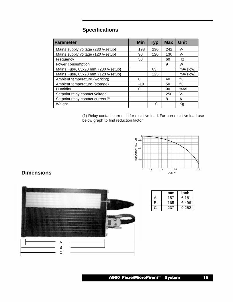
Parameter Min Typ Max UnitMains supply voltage (230 V-setup) 198 230 242 V-Mains supply voltage (120 V-setup) 90 120 130 V-Frequency 50 60 HzPower consumption 9 WMains Fuse, 05x20 mm. (230 V-setup) 63 mA(slow)Mains Fuse, 05x20 mm. (120 V-setup) 125 mA(slow)Ambient temperature (working) 0 40 0CAmbient temperature (storage) -10 50 0CHumidity 0 90 %rel.Setpoint relay contact voltage 250 V-Setpoint relay contact current
(1) 8 A
Weight 1.0 Kg.
(1) Relay contact current is for resistive load. For non-resistive load usebelow graph to find reduction factor.
Specifications
Dimensions
mm inchA 157 6.181B 165 6.496C 237 9.252
ABC
�� ����� ������ ������������ ������ ������������ ������ ������������ ������ ������������ ������ �������TM� ������� ������� ������� ������� ������
Changing fuse
The A900 contains a mains fuse protection. The fuse will blowif the instrument is supplied with higher voltage than specifiedor in case of instrument malfunction
1. Turn the instrument off and remove all connectors and finallyremove the power line.
2. Remove the 4 screws at the rear panel.3. Softly insert a screwdriver between the rear panel and the
instrument case and easily pull out until the rear panel is loose.4. Change the fuse at the fuse holder with only approved fuses with
proper rating.5. Assemble the instrument again.
If the fuse blows again shortly after change, the instrument has most likely amalfunction and should be returned to HPSTM Products for repair.
230 Vac setup 120 Vac setup63mA T, 250 V, ø5x20 mm 120mA T, 250 V, ø5x20 mm
Connectors
Product description Order code
Setpoint relay connector 100010757 Analog output connector 100010754
Transducer extension cables
Cable runs up to 300 ft. are possible between the A900 and the transducer.
Product description Order code
Transducer extension cable 10 ft. 103170006SH Transducer extension cable 25 ft. 103170007SH Transducer extension cable 50 ft. 103170008SH
������� ������ ������������ ������ ������������ ������ ������������ ������ ������������ ������ �������TM � ������� ������� ������� ������� ������
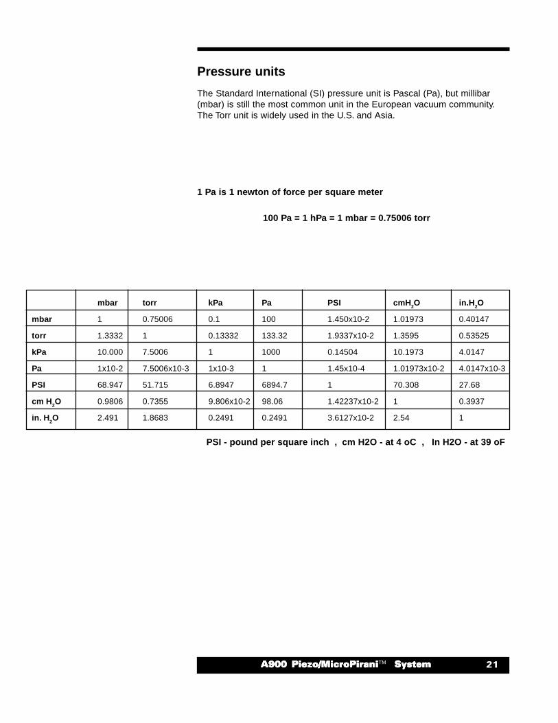
Pressure units
The Standard International (SI) pressure unit is Pascal (Pa), but millibar(mbar) is still the most common unit in the European vacuum community.The Torr unit is widely used in the U.S. and Asia.
1 Pa is 1 newton of force per square meter
100 Pa = 1 hPa = 1 mbar = 0.75006 torr
PSI - pound per square inch , cm H2O - at 4 oC , In H2O - at 39 oF
mbar torr kPa Pa PSI cmH2O in.H2O
mbar 1 0.75006 0.1 100 1.450x10⁻² 1.01973 0.40147
torr 1.3332 1 0.13332 133.32 1.9337x10⁻² 1.3595 0.53525
kPa 10.000 7.5006 1 1000 0.14504 10.1973 4.0147
Pa 1x10⁻² 7.5006x10⁻³ 1x10⁻³ 1 1.45x10⁻⁴ 1.01973x10⁻² 4.0147x10⁻³
PSI 68.947 51.715 6.8947 6894.7 1 70.308 27.68
cm H2O 0.9806 0.7355 9.806x10⁻² 98.06 1.42237x10⁻² 1 0.3937
in. H2O 2.491 1.8683 0.2491 0.2491 3.6127x10⁻² 2.54 1
�� ����� ������ ������������ ������ ������������ ������ ������������ ������ ������������ ������ �������TM� ������� ������� ������� ������� ������
Extent of the WarrantyMKS Instruments, Inc., HPSTM Products Inc., warrants the HPSTM Series A900 Vacuum Transducer and
its accessories to be free from defects in materials and workmanship for one (1) year from the date ofshipment by HPSTM or authorized representative to the original purchaser (PURCHASER). Any product orparts of the product repaired or replaced by HPSTM under this warranty are warranted only for the remainingunexpired part of its one (1) year original warranty period. After expiration of the applicable warranty period,the PURCHASER shall be charged HPSTM’ current prices for parts and labor, plus any transportation forany repairs or replacement.
ALL EXPRESS AND IMPLIED WARRANTIES, INCLUDING THE IMPLIED WARRANTIES OFMERCHANTABILITY AND FITNESS FOR A PARTICULAR PURPOSE, ARE LIMITED TO THE WARRANTYPERIOD. NO WARRANTIES, EXPRESS OR IMPLIED, WILL APPLY AFTER THIS PERIOD.
Warranty ServiceThe obligations of HPSTM under this warranty shall be at its option: (1) to repair, replace, or adjust the product
so that it meets applicable product specifications published by HPSTM or (2) to refund the purchase price.
What Is Not CoveredThe product is subject to above terms only if located in the country of the seller from whom the product
was purchased. The above warranties do not apply to:I. Damages or malfunctions due to failure to provide reasonable and necessary maintenance in
accordance with HPSTM operating instructions.II. Damages or malfunctions due to chemical or electrolytic influences or use of the product in
working environments outside the specification.III. Fuses and all expendable items which by their nature or limited lifetime may not function for a year. If
such items fail to give reasonable service for a reasonable period of time within the warranty periodof the product; they will, at the option of HPSTM, be repaired or replaced.
IV. Defects or damages caused by modifications and repairs effected by the original PURCHASER orthird parties not authorized in the manual.
Condition of Returned ProductsHPSTM will not accept for repair, replacement, or credit any product which is asserted to be defective by
the PURCHASER, or any product for which paid or unpaid service is desired, if the product is contaminatedwith potentially corrosive, reactive, harmful, or radioactive materials, gases, or chemicals.
When products are used with toxic chemicals, or in an atmosphere that is dangerous to the health ofhumans, or is environmentally unsafe, it is the responsibility of the PURCHASER to have the productcleaned by an independent agency skilled and approved in the handling and cleaning of contaminatedmaterials before the product will be accepted by HPSTM for repair and/or replacement.
In the course of implementing this policy, HPSTM Customer Service Personnel may inquire of thePURCHASER whether the product has been contaminated with or exposed to potentially corrosive,reactive, harmful, or radioactive materials, gases, or chemicals when the PURCHASER requests a returnauthorization. Notwithstanding such inquiries, it is the responsibility of the PURCHASER to ensure that noproducts are returned to HPSTM which have been contaminated in the aforementioned manner.
Other Rights and RemediesI. These remedies are exclusive. HPSTM SHALL NOT BE LIABLE FOR CONSEQUENTIAL DAMAGES,
FOR ANTICIPATED OR LOST PROFITS, INCIDENTAL DAMAGES OR LOSS OF TIME, OR OTHERLOSSES INCURRED BY THE PURCHASER OR BY ANY THIRD PARTY IN CONNECTION WITHTHE PRODUCT COVERED BY THIS WARRANTY, OR OTHERWISE. Some states do not allowexclusion or limitation of incidental or consequential damage or do not allow the limitation on howlong an implied warranty lasts. If such laws apply, the limitations or exclusions expressed hereinmay not apply to PURCHASER.
II. Unless otherwise explicitly agreed in writing, it is understood that these are the only writtenwarranties given by HPSTM. Any statements made by any persons, including representatives ofHPSTM, which are inconsistent or in conflict with the terms of the warranty shall not be binding onHPSTM unless reduced to writing and approved by an authorized officer of HPSTM.
III. This warranty gives PURCHASER specific legal rights, and PURCHASER may also have other rightswhich vary from state to state.
IV. For HPSTM products sold outside of the U.S., contact your MKS representative for warrantyinformation and service.
Warranty PerformanceTo obtain warranty satisfaction, contact the following: MKS Instruments, Inc., HPSTM Products, Inc., 5330
Sterling Drive, Boulder, CO 80301, USA, at phone number (303) 449-9861.
Warranty

������� ������ ������������ ������ ������������ ������ ������������ ������ ������������ ������ �������TM � ������� ������� ������� ������� ������
Notes

�� ����� ������ ������������ ������ ������������ ������ ������������ ������ ������������ ������ �������TM� ������� ������� ������� ������� ������