hpgl2-rtl referenceguide 5961-3526 540pages sep96
TRANSCRIPT
8/12/2019 HPGL2-RTL ReferenceGuide 5961-3526 540pages Sep96
http://slidepdf.com/reader/full/hpgl2-rtl-referenceguide-5961-3526-540pages-sep96 1/539
Company confidential. HP-GL/2 and HP RTL Reference Guide, draft 2. Freeze Status: open
This is the black on page i (seq: 1)
Hewlett-PackardRaster Transfer Language
The HP-GL/2 and HP RTLReference GuideA Handbook for Program Developers
Hewlett-PackardGraphics Language/2
8/12/2019 HPGL2-RTL ReferenceGuide 5961-3526 540pages Sep96
http://slidepdf.com/reader/full/hpgl2-rtl-referenceguide-5961-3526-540pages-sep96 2/539
This is the black on page ii (seq: 2)
Company confidential. HP-GL/2 and HP RTL Reference Guide, draft 2. Freeze Status: open
Copyright Hewlett-Packard Company 1990, 1992,1994, 1996
HP Part number of this manual:5961–3526
First edition, October 1993Second edition, September 1996
Bi-Tronics, HP-GL, HP-GL/2, and PCL are trademarksof Hewlett-Packard Company.
AppleTalk is a trademark of Apple Computer Inc.
Microsoft is a registered trademark of Microsoft Cor-poration.
PostScript is a trademark of Adobe Systems Incorpo-rated which may be registered in certain jurisdictions.
See Appendix C for a note on page 480 about other trade-marks.
Library of Congress Cataloging-in-Publication Data
The HP-GL/2 and HP RTL Reference Guide: A Hand-book for Program Developers /
Hewlett-Packardp. cm.
Includes IndexISBN 0–201–63325–61. HP-GL/2 (Computer program language)
2. HP RTL (Computer program language)3. Computer graphics. I. Hewlett-Packard.QA.76.73.H6H52 1996
ISBN 0–201–63325–6
Notices
This document contains proprietary information, whichis protected by copyright. All rights are reserved. Theinformation contained in this document is subject tochange without notice and should not be construed as acommitment by the Hewlett-Packard Company. Nopart of the document may be photocopied, reproduced,or translated to another language without the prior writ-ten consent of Hewlett-Packard Company.
Hewlett-Packard assumes no responsibility for anyerrors that may appear in this document nor does itmake expressed or implied warranty of any kindwith regard to this material, including, but not lim-ited to, the implied warranties of merchantabilityand fitness for a particular purpose. The Hew-lett-Packard Company shall not be liable for incidental
or consequential damages in connection with, or aris-ing out of the furnishing, performance, or use of thisdocument and the program material which it describes.
The cover illustration, reproduced by kind permissionof the Ajuntament of Barcelona, Spain, shows the CasaBatlló, built in 1904–1906 by the Catalan architectAntoni Gaudí. The original photograph used to pro-vide the master of the cover was printed on aHewlett-Packard DesignJet 755CM printer.
The publisher offers discounts on this book when or-dered in quantity for special sales. For moreinformation please contact:
Corporate & Professional Publishing GroupAddison-Wesley Publishing CompanyOne Jacob WayReading, Massachusetts 01867U.S.A.
Text printed on recycled and acid-free paper.
Hewlett-Packard CompanyBarcelona DivisionAvda. Graells, 50108190 Sant Cugat del VallèsBarcelona, Spain
8/12/2019 HPGL2-RTL ReferenceGuide 5961-3526 540pages Sep96
http://slidepdf.com/reader/full/hpgl2-rtl-referenceguide-5961-3526-540pages-sep96 3/539
iii
This is the black on page iii (seq: 3)
Company confidential. HP-GL/2 and HP RTL Reference Guide, draft 2. Freeze Status: open
Preface
This is a generic guide to HP-GL/2 (Hewlett-Packard’s standardized Graphics Language) andHP RTL (Hewlett-Packard’s Raster Transfer Language) supported by many HP graphics peripher-als. This manual describes each of the instructions of HP-GL/2 and each of the commands of HP RTL, without relying on a specific device or technology.
You must use a programming language in addition to HP-GL/2 or HP RTL. However, this book will not teach you how to program your computer. Your method of programming will depend onyour computer system, the programming language you use, and your level of expertise. Thisbook, though, does give recommendations on getting the most from your device.
This book describes how to write programs using HP-GL/2 and HP RTL.
PART 1 deals with general concepts and principles.
Chapter 1 on page 3 describes the concepts needed to create programs that use HP-GL/2 andHP RTL, including plotting concepts, vector and raster images, defining the limits of yourpicture, the coordinate system used, units of measure, and switching from one plottingcontext to another.
PART 2 describes HP-GL/2.
Chapter 2 on page 17 describes the groups of instructions that make up HP-GL/2, the statusof the pen and its location, how to scale pictures, and the notation used to define HP-GL/2
instructions.Chapter 3 on page 29 describes the HP-GL/2 kernel, that is, the core set of instructionssupported by all HP-GL/2 devices. Each group is explained in detail, with examples. TheHP-GL/2 print model is also described.
Chapter 4 on page 77 describes the groups of extension instructions, that are provided forspecific types of peripheral devices.
Chapter 5 on page 95 starts with a reference summary of all the HP-GL/2 instructions, inalphabetical order of their names, and is followed by a complete description of all the HP-GL/2 instructions, in alphabetical order of their two-letter acronyms.
Chapter 6 on page 331 summarizes the elements of HP-GL/2 that are dependent on thedevice in use.
PART 3 describes HP RTL.Chapter 7 on page 337 describes the concepts needed to create HP RTL raster programs. Itincludes a description of the notation used to define HP RTL commands.
Chapter 8 on page 341 explains how to set the limits of your images, how to set the imageresolution, how to scale images, and also describes the coordinate system used for placingimages on the page.
Chapter 9 on page 351 describes how to define colors, the use of color modes and palettes,and how to use indexes to select colors. It also explains how to use patterns.
This is the blue on page iii (seq: 3)
8/12/2019 HPGL2-RTL ReferenceGuide 5961-3526 540pages Sep96
http://slidepdf.com/reader/full/hpgl2-rtl-referenceguide-5961-3526-540pages-sep96 4/539
iv
This is the black on page iv (seq: 4)
Company confidential. HP-GL/2 and HP RTL Reference Guide, draft 2. Freeze Status: open
Chapter 10 on page 365 describes the interactions between picture elements. It explainshow patterns and texture relate to raster images through logical operations, the default printmodel, and image and pattern transparency.
Chapter 11 on page 375 describes how to transfer raster data to the device. It includes adescription of what happens when overflow occurs, and the various supported methods of compressing data.
Chapter 12 on page 391 describes the interactions between HP RTL and physical devicesettings, HP-GL/2, and PJL.
Chapter 13 on page 397 contains some examples of HP RTL raster programs.
Chapter 14 on page 403 lists, in alphabetical order of their names, the HP RTL commandsused in raster programs.
Chapter 15 on page 455 contains a summary of the features of HP RTL that may vary fromdevice to device.
PART 4 consists of some general appendixes.Appendix A on page 461 has some programming hints on getting the best from your system.
Appendix B on page 475 lists the logical operations used in HP-GL/2 and HP RTL.
Appendix C on page 477 lists the font kind and value parameters used in the HP-GL/2 AD(Alternate Font Definition) and SD (Standard Font Definition) instructions.
A Glossary of terms and abbreviations and an Index follow at the end of the book.
The Product Comparison Guide for HP Languages on HP Plotters and Large-Format Printers,HP part number 5959–9734, shows the differences between the implementations of HP-GL/2 onvarious HP devices.
The PCL 5 Printer Language Technical Reference Manual, HP part number 5961–0509, de-scribes the commands of PCL 5.
The PCL 5 Comparison Guide, HP part number 5961-0602, describes which HP-GL/2 instruc-tions are supported on HP LaserJet series printers.
The PJL Technical Reference Manual, HP part number 5010–3999, describes the Printer Job Lan-guage.
In this book, numbers are expressed using SI (International System of Units) standards. Numberswith more than four digits are placed in groups of three, separated by a space instead of a comma,counting to both sides of the decimal point (for example, 54 321.123 45).
type denotes an ASCII control character, such as (escape), (carriage return), (line feed), or (end-of-text).
All references to the RS-232-C interface apply equally to the CCITT V.24 interface.
See page 26 (for HP-GL/2) and page 338 (for HP RTL) for descriptions of other notational con-ventions used in this book. The term instruction refers to the interface with HP-GL/2; the termcommand is used consistently to refer to the interface with HP RTL or PCL. See the Glossary onpage 483 for explanations of other terms used.
8/12/2019 HPGL2-RTL ReferenceGuide 5961-3526 540pages Sep96
http://slidepdf.com/reader/full/hpgl2-rtl-referenceguide-5961-3526-540pages-sep96 5/539
v
This is the black on page v (seq: 5)
Company confidential. HP-GL/2 and HP RTL Reference Guide, draft 2. Freeze Status: open
Contents
This is the blue on page v (seq: 5)
8/12/2019 HPGL2-RTL ReferenceGuide 5961-3526 540pages Sep96
http://slidepdf.com/reader/full/hpgl2-rtl-referenceguide-5961-3526-540pages-sep96 6/539
vi
This is the black on page vi (seq: 6)
Company confidential. HP-GL/2 and HP RTL Reference Guide, draft 2. Freeze Status: open
8/12/2019 HPGL2-RTL ReferenceGuide 5961-3526 540pages Sep96
http://slidepdf.com/reader/full/hpgl2-rtl-referenceguide-5961-3526-540pages-sep96 7/539
vii
This is the black on page vii (seq: 7)
Company confidential. HP-GL/2 and HP RTL Reference Guide, draft 2. Freeze Status: open
8/12/2019 HPGL2-RTL ReferenceGuide 5961-3526 540pages Sep96
http://slidepdf.com/reader/full/hpgl2-rtl-referenceguide-5961-3526-540pages-sep96 8/539
viii
This is the black on page viii (seq: 8)
Company confidential. HP-GL/2 and HP RTL Reference Guide, draft 2. Freeze Status: open
8/12/2019 HPGL2-RTL ReferenceGuide 5961-3526 540pages Sep96
http://slidepdf.com/reader/full/hpgl2-rtl-referenceguide-5961-3526-540pages-sep96 9/539
ix
This is the black on page ix (seq: 9)
Company confidential. HP-GL/2 and HP RTL Reference Guide, draft 2. Freeze Status: open
8/12/2019 HPGL2-RTL ReferenceGuide 5961-3526 540pages Sep96
http://slidepdf.com/reader/full/hpgl2-rtl-referenceguide-5961-3526-540pages-sep96 10/539
x
This is the black on page x (seq: 10)
Company confidential. HP-GL/2 and HP RTL Reference Guide, draft 2. Freeze Status: open
8/12/2019 HPGL2-RTL ReferenceGuide 5961-3526 540pages Sep96
http://slidepdf.com/reader/full/hpgl2-rtl-referenceguide-5961-3526-540pages-sep96 11/539
xi
This is the black on page xi (seq: 11)
Company confidential. HP-GL/2 and HP RTL Reference Guide, draft 2. Freeze Status: open
8/12/2019 HPGL2-RTL ReferenceGuide 5961-3526 540pages Sep96
http://slidepdf.com/reader/full/hpgl2-rtl-referenceguide-5961-3526-540pages-sep96 12/539
xii
This is the black on page xii (seq: 12)
Company confidential. HP-GL/2 and HP RTL Reference Guide, draft 2. Freeze Status: open
8/12/2019 HPGL2-RTL ReferenceGuide 5961-3526 540pages Sep96
http://slidepdf.com/reader/full/hpgl2-rtl-referenceguide-5961-3526-540pages-sep96 13/539
xiii
This is the black on page xiii (seq: 13)
Company confidential. HP-GL/2 and HP RTL Reference Guide, draft 2. Freeze Status: open
8/12/2019 HPGL2-RTL ReferenceGuide 5961-3526 540pages Sep96
http://slidepdf.com/reader/full/hpgl2-rtl-referenceguide-5961-3526-540pages-sep96 14/539
xiv
This is the black on page xiv (seq: 14)
Company confidential. HP-GL/2 and HP RTL Reference Guide, draft 2. Freeze Status: open
8/12/2019 HPGL2-RTL ReferenceGuide 5961-3526 540pages Sep96
http://slidepdf.com/reader/full/hpgl2-rtl-referenceguide-5961-3526-540pages-sep96 15/539
xv
This is the black on page xv (seq: 15)
Company confidential. HP-GL/2 and HP RTL Reference Guide, draft 2. Freeze Status: open
List of Figures
This is the blue on page xv (seq: 15)
8/12/2019 HPGL2-RTL ReferenceGuide 5961-3526 540pages Sep96
http://slidepdf.com/reader/full/hpgl2-rtl-referenceguide-5961-3526-540pages-sep96 16/539
xvi
This is the black on page xvi (seq: 16)
Company confidential. HP-GL/2 and HP RTL Reference Guide, draft 2. Freeze Status: open
8/12/2019 HPGL2-RTL ReferenceGuide 5961-3526 540pages Sep96
http://slidepdf.com/reader/full/hpgl2-rtl-referenceguide-5961-3526-540pages-sep96 17/539
xvii
This is the black on page xvii (seq: 17)
Company confidential. HP-GL/2 and HP RTL Reference Guide, draft 2. Freeze Status: open
8/12/2019 HPGL2-RTL ReferenceGuide 5961-3526 540pages Sep96
http://slidepdf.com/reader/full/hpgl2-rtl-referenceguide-5961-3526-540pages-sep96 18/539
xviii
This is the black on page xviii (seq: 18)
Company confidential. HP-GL/2 and HP RTL Reference Guide, draft 2. Freeze Status: open
8/12/2019 HPGL2-RTL ReferenceGuide 5961-3526 540pages Sep96
http://slidepdf.com/reader/full/hpgl2-rtl-referenceguide-5961-3526-540pages-sep96 19/539
1
This is the black on page 1 (seq: 19)
Company confidential. HP-GL/2 and HP RTL Reference Guide, draft 2. Freeze Status: open
PART 1: Introduction to Plotting andPrinting Using HP-GL/2 and HP RTL
This Part contains the following sections:
This is the blue on page 1 (seq: 19)
P R I N T I N G
P L O T T I N
G &

8/12/2019 HPGL2-RTL ReferenceGuide 5961-3526 540pages Sep96
http://slidepdf.com/reader/full/hpgl2-rtl-referenceguide-5961-3526-540pages-sep96 20/539
2
This is the black on page 2 (seq: 20)
Company confidential. HP-GL/2 and HP RTL Reference Guide, draft 2. Freeze Status: open
8/12/2019 HPGL2-RTL ReferenceGuide 5961-3526 540pages Sep96
http://slidepdf.com/reader/full/hpgl2-rtl-referenceguide-5961-3526-540pages-sep96 21/539
3
This is the black on page 3 (seq: 21)
Company confidential. HP-GL/2 and HP RTL Reference Guide, draft 2. Freeze Status: open
Chapter 1: Plotting and Printing
Plotting and Printing Concepts
There are three types of object that you may want to print or plot on your HP device: vectors,images, and characters.
Vector objects are composed of straight lines, and are normally defined using the instructions of HP-GL/2. Combinations of straight lines can be used to form rectangles and other polygons.They can also be used to create curves, and HP-GL/2 contains instructions that let you createarcs, circles, ellipses, and more complex curves. You can also use HP-GL/2 instructions to fillareas with patterns of various types. HP-GL/2 is also used to define the logical page , picture frame , or window, which is that part of the physical page on which objects are placed.
Characters are normally printed using the commands of the PCL Printer Language, which giveyou access to a wide range of character sets ( fonts). PCL also allows you to define graphicslimits. See the PCL 5 Technical Reference Manual for more information about these com-mands. HP-GL/2 can also be used to create character labels (text) that appear on drawings.
Image objects, such as scanned photographs or other objects, are normally placed on theprinted or plotted page using the commands of Hewlett-Packard’s Raster Transfer Language,HP RTL. You can also use HP RTL to shade areas. HP RTL is essentially a subset of PCL.
You can use HP-GL/2 in conjunction with either PCL or HP RTL to create different parts of a
single drawing or picture, or to create consecutive pages in different environments. There arecommands and instructions that allow you to switch from one environment to another. Plottersand printers that support both HP-GL/2 and HP RTL or PCL are described as dual-context de-vices.
Printing with HP-GL/2 requires leaving the PCL or HP RTL mode and entering HP-GL/2 mode.Switching between modes involves only a few commands or instructions, and software applica-tions may easily switch between the modes as needed.
HP-GL/2 graphics may be created within application software, or imported from existing ap-plications. For various types of images (many technical drawings and business graphics, forexample), it is advantageous to use vector graphics instead of raster graphics. The advantagesinclude faster I/O transfer of large objects and smaller disk storage requirements.
As a guideline, use raster graphics for small, complex images, or those images that cannot be
accomplished with HP-GL/2 (such as scanned photographs). Use HP-GL/2 for images thatwould involve a large amount of I/O data transfer if printed using raster graphics, or for draw-ings that are already in HP-GL/2 format. If the image is easier to describe using vectors insteadof raster lines, it usually prints faster using HP-GL/2.
Further detailed discussion of PCL is beyond the scope of this book, except where it directlyinteracts with HP-GL/2 and HP RTL; for more information about PCL, refer to the books listedin the Preface on page iii.
This is the blue on page 3 (seq: 21)
P R I N T I N G
P L O T T I N
G &
8/12/2019 HPGL2-RTL ReferenceGuide 5961-3526 540pages Sep96
http://slidepdf.com/reader/full/hpgl2-rtl-referenceguide-5961-3526-540pages-sep96 22/539
4
This is the black on page 4 (seq: 22)
Company confidential. HP-GL/2 and HP RTL Reference Guide, draft 2. Freeze Status: open
Vectors and Raster Images
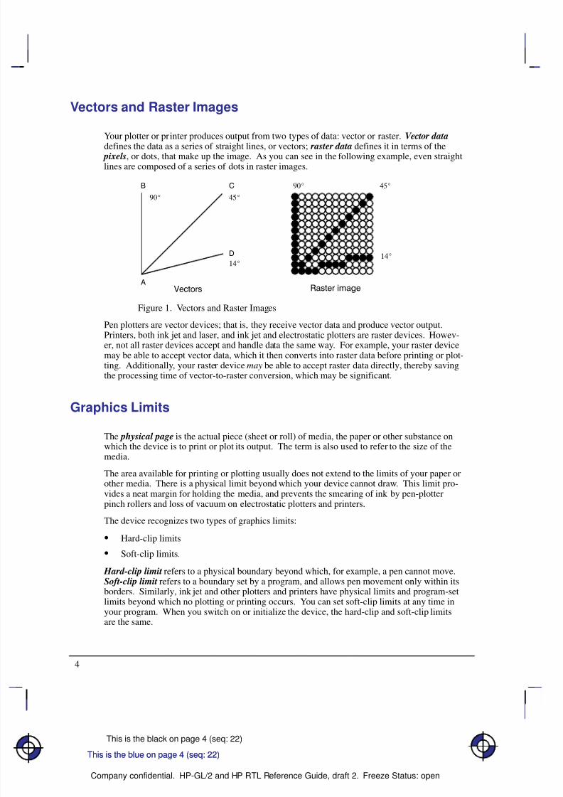
Your plotter or printer produces output from two types of data: vector or raster. Vector datadefines the data as a series of straight lines, or vectors; raster data defines it in terms of the pixels, or dots, that make up the image. As you can see in the following example, even straightlines are composed of a series of dots in raster images.
Figure 1. Vectors and Raster Images
Pen plotters are vector devices; that is, they receive vector data and produce vector output.Printers, both ink jet and laser, and ink jet and electrostatic plotters are raster devices. Howev-er, not all raster devices accept and handle data the same way. For example, your raster devicemay be able to accept vector data, which it then converts into raster data before printing or plot-ting. Additionally, your raster device may be able to accept raster data directly, thereby savingthe processing time of vector-to-raster conversion, which may be significant.
Graphics Limits
The physical page is the actual piece (sheet or roll) of media, the paper or other substance onwhich the device is to print or plot its output. The term is also used to refer to the size of themedia.
The area available for printing or plotting usually does not extend to the limits of your paper orother media. There is a physical limit beyond which your device cannot draw. This limit pro-vides a neat margin for holding the media, and prevents the smearing of ink by pen-plotterpinch rollers and loss of vacuum on electrostatic plotters and printers.
The device recognizes two types of graphics limits:
Hard-clip limits
Soft-clip limits.
Hard-clip limit refers to a physical boundary beyond which, for example, a pen cannot move.Soft-clip limit refers to a boundary set by a program, and allows pen movement only within itsborders. Similarly, ink jet and other plotters and printers have physical limits and program-setlimits beyond which no plotting or printing occurs. You can set soft-clip limits at any time inyour program. When you switch on or initialize the device, the hard-clip and soft-clip limitsare the same.
This is the blue on page 4 (seq: 22)This is the blue on page 4 (seq: 22)
8/12/2019 HPGL2-RTL ReferenceGuide 5961-3526 540pages Sep96
http://slidepdf.com/reader/full/hpgl2-rtl-referenceguide-5961-3526-540pages-sep96 23/539
5
This is the black on page 5 (seq: 23)
Company confidential. HP-GL/2 and HP RTL Reference Guide, draft 2. Freeze Status: open
Í Í Í Í Í
Í Í Í Í Í
Í Í Í Í Í
Í Í Í Í Í
Í Í Í Í Í
Í Í Í Í Í
Í Í Í Í Í
Í Í Í Í Í
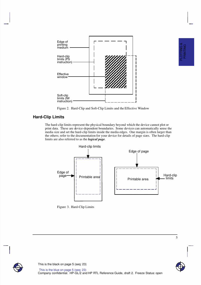
Figure 2. Hard-Clip and Soft-Clip Limits and the Effective Window
Hard-Clip Limits
The hard-clip limits represent the physical boundary beyond which the device cannot plot orprint data. These are device-dependent boundaries. Some devices can automatically sense themedia size and set the hard-clip limits inside the media edges. One margin is often larger thanthe others; refer to the documentation for your device for details of page sizes. The hard-cliplimits are also referred to as the logical page.
Hard-clip limits
Hard-cliplimits
Edge of page
Edge ofpage Printable area
Printable area
Figure 3. Hard-Clip Limits
This is the blue on page 5 (seq: 23)
P R I N T I N G
P L O T T I N
G &
8/12/2019 HPGL2-RTL ReferenceGuide 5961-3526 540pages Sep96
http://slidepdf.com/reader/full/hpgl2-rtl-referenceguide-5961-3526-540pages-sep96 24/539
6
This is the black on page 6 (seq: 24)
Company confidential. HP-GL/2 and HP RTL Reference Guide, draft 2. Freeze Status: open
Soft-Clip Limits
Soft-clip limits temporarily restrict the positioning of data to a specified area of the page.
These limits let you draw attention to a particular set of data and they are often called windows.Usually soft-clip limits ensure that nothing is drawn beyond a particular portion of the page.
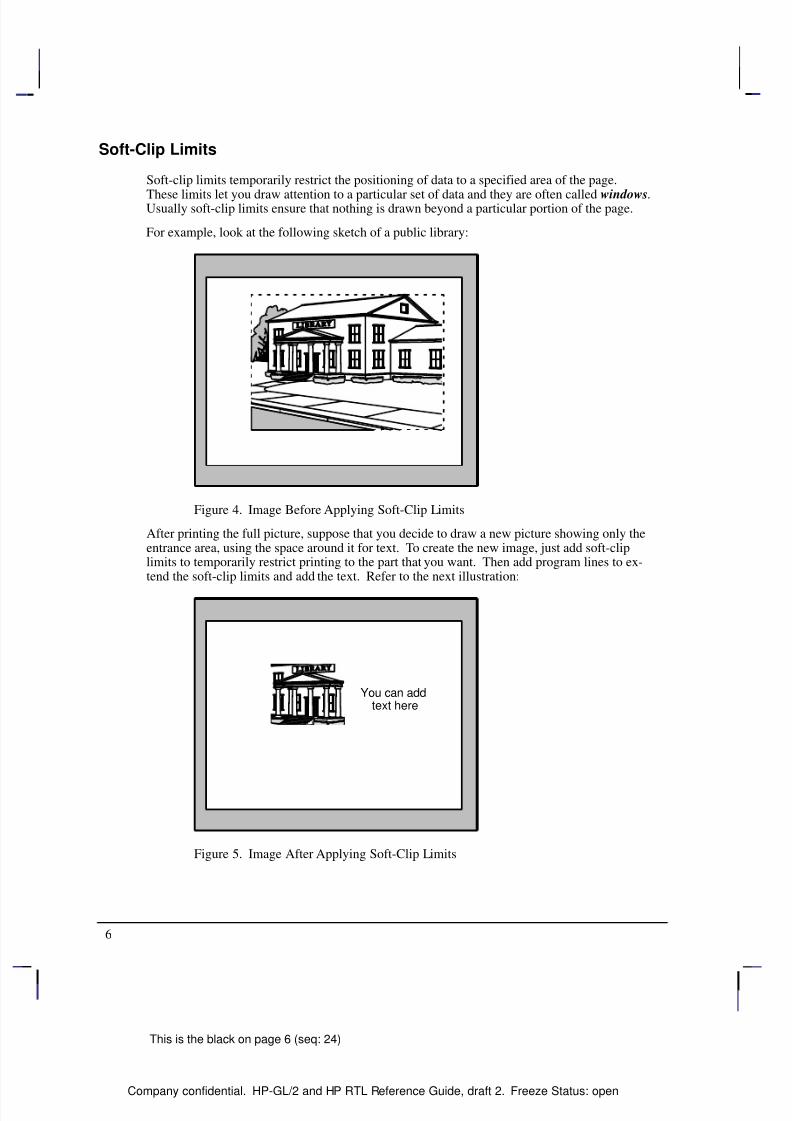
For example, look at the following sketch of a public library:
Figure 4. Image Before Applying Soft-Clip Limits
After printing the full picture, suppose that you decide to draw a new picture showing only theentrance area, using the space around it for text. To create the new image, just add soft-cliplimits to temporarily restrict printing to the part that you want. Then add program lines to ex-tend the soft-clip limits and add the text. Refer to the next illustration:
You can addtext here
Figure 5. Image After Applying Soft-Clip Limits
8/12/2019 HPGL2-RTL ReferenceGuide 5961-3526 540pages Sep96
http://slidepdf.com/reader/full/hpgl2-rtl-referenceguide-5961-3526-540pages-sep96 25/539
7
This is the black on page 7 (seq: 25)
Company confidential. HP-GL/2 and HP RTL Reference Guide, draft 2. Freeze Status: open
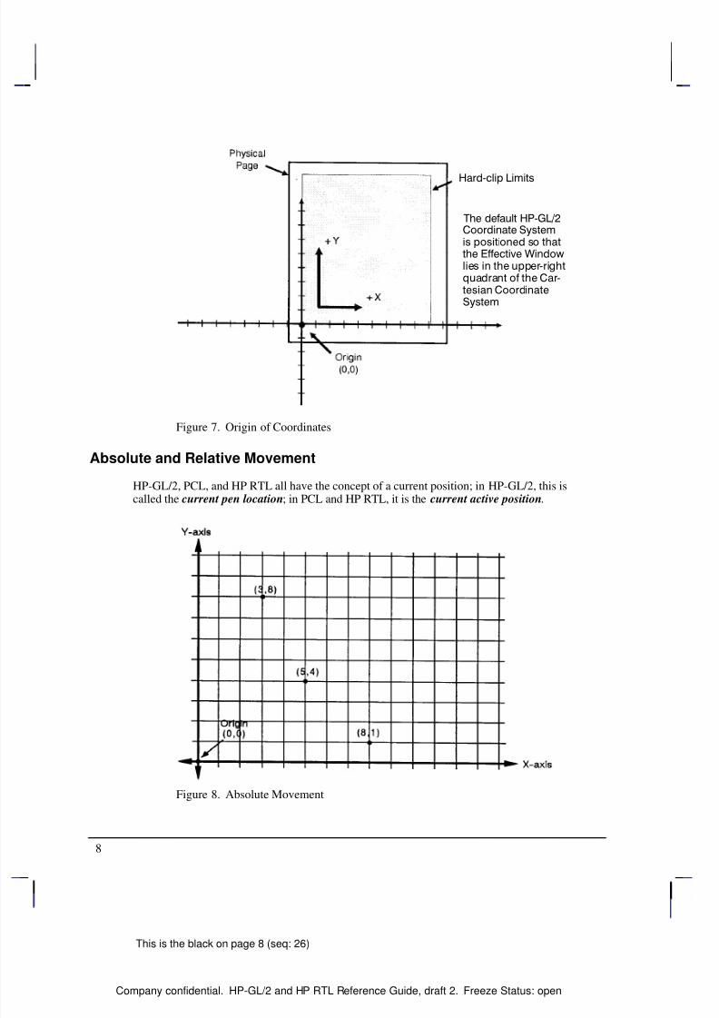
The Coordinate System
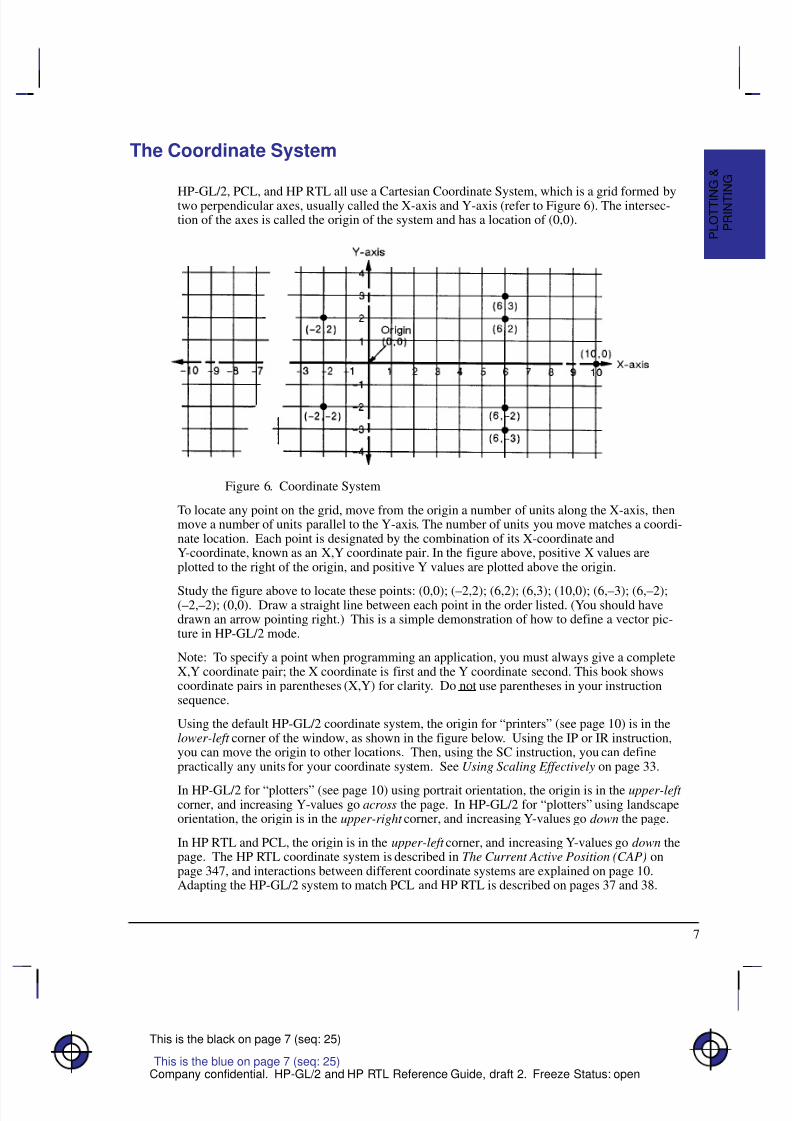
HP-GL/2, PCL, and HP RTL all use a Cartesian Coordinate System, which is a grid formed bytwo perpendicular axes, usually called the X-axis and Y-axis (refer to Figure 6). The intersec-tion of the axes is called the origin of the system and has a location of (0,0).
Figure 6. Coordinate System
To locate any point on the grid, move from the origin a number of units along the X-axis, thenmove a number of units parallel to the Y-axis. The number of units you move matches a coordi-nate location. Each point is designated by the combination of its X-coordinate andY-coordinate, known as an X,Y coordinate pair. In the figure above, positive X values areplotted to the right of the origin, and positive Y values are plotted above the origin.
Study the figure above to locate these points: (0,0); (–2,2); (6,2); (6,3); (10,0); (6,–3); (6,–2);(–2,–2); (0,0). Draw a straight line between each point in the order listed. (You should havedrawn an arrow pointing right.) This is a simple demonstration of how to define a vector pic-ture in HP-GL/2 mode.
Note: To specify a point when programming an application, you must always give a completeX,Y coordinate pair; the X coordinate is first and the Y coordinate second. This book showscoordinate pairs in parentheses (X,Y) for clarity. Do not use parentheses in your instructionsequence.
Using the default HP-GL/2 coordinate system, the origin for “printers” (see page 10) is in thelower-left corner of the window, as shown in the figure below. Using the IP or IR instruction,you can move the origin to other locations. Then, using the SC instruction, you can definepractically any units for your coordinate system. See Using Scaling Effectively on page 33.
In HP-GL/2 for “plotters” (see page 10) using portrait orientation, the origin is in the upper-left corner, and increasing Y-values go across the page. In HP-GL/2 for “plotters” using landscapeorientation, the origin is in the upper-right corner, and increasing Y-values go down the page.
In HP RTL and PCL, the origin is in the upper-left corner, and increasing Y-values go down thepage. The HP RTL coordinate system is described in The Current Active Position (CAP) onpage 347, and interactions between different coordinate systems are explained on page 10.Adapting the HP-GL/2 system to match PCL and HP RTL is described on pages 37 and 38.
This is the blue on page 7 (seq: 25)
P R I N T I N G
P L O T T I N
G &
8/12/2019 HPGL2-RTL ReferenceGuide 5961-3526 540pages Sep96
http://slidepdf.com/reader/full/hpgl2-rtl-referenceguide-5961-3526-540pages-sep96 26/539
8
This is the black on page 8 (seq: 26)
Company confidential. HP-GL/2 and HP RTL Reference Guide, draft 2. Freeze Status: open
Figure 7. Origin of Coordinates
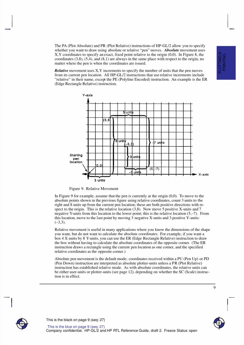
Absolute and Relative Movement
HP-GL/2, PCL, and HP RTL all have the concept of a current position; in HP-GL/2, this iscalled the current pen location; in PCL and HP RTL, it is the current active position.
Figure 8. Absolute Movement
8/12/2019 HPGL2-RTL ReferenceGuide 5961-3526 540pages Sep96
http://slidepdf.com/reader/full/hpgl2-rtl-referenceguide-5961-3526-540pages-sep96 27/539
9
This is the black on page 9 (seq: 27)
Company confidential. HP-GL/2 and HP RTL Reference Guide, draft 2. Freeze Status: open
The PA (Plot Absolute) and PR (Plot Relative) instructions of HP-GL/2 allow you to specifywhether you want to draw using absolute or relative “pen” moves. Absolute movement usesX,Y coordinates to specify an exact, fixed point relative to the origin (0,0). In Figure 8, the
coordinates (3,8), (5,4), and (8,1) are always in the same place with respect to the origin, nomatter where the pen is when the coordinates are issued.
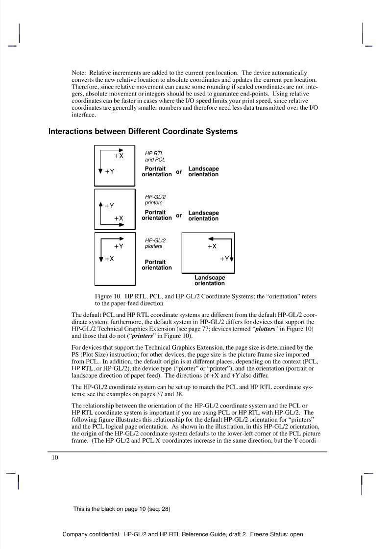
Relative movement uses X,Y increments to specify the number of units that the pen movesfrom its current pen location. All HP-GL/2 instructions that use relative increments include“relative” in their name, except the PE (Polyline Encoded) instruction. An example is the ER(Edge Rectangle Relative) instruction.
Figure 9. Relative Movement
In Figure 9 for example, assume that the pen is currently at the origin (0,0). To move to theabsolute points shown in the previous figure using relative coordinates, count 3 units to theright and 8 units up from the current pen location; these are both positive directions with re-spect to the origin. This is the relative location (3,8). Now move 5 positive X-units and 7negative Y-units from this location to the lower point; this is the relative location (5,–7). Fromthis location, move to the last point by moving 3 negative X-units and 3 positive Y-units:(–3,3).
Relative movement is useful in many applications where you know the dimensions of the shapeyou want, but do not want to calculate the absolute coordinates. For example, if you want abox 4 X-units by 8 Y-units, you can use the ER (Edge Rectangle Relative) instruction to draw
the box without having to calculate the absolute coordinates of the opposite corner. (The ERinstruction draws a rectangle using the current pen location as one corner, and the specifiedrelative coordinates as the opposite corner.)
Absolute pen movement is the default mode; coordinates received within a PU (Pen Up) or PD(Pen Down) instruction are interpreted as absolute plotter-units unless a PR (Plot Relative)instruction has established relative mode. As with absolute coordinates, the relative units canbe either user-units or plotter-units (see page 12), depending on whether the SC (Scale) instruc-tion is in effect.
This is the blue on page 9 (seq: 27)
P R I N T I N G
P L O T T I N
G &
8/12/2019 HPGL2-RTL ReferenceGuide 5961-3526 540pages Sep96
http://slidepdf.com/reader/full/hpgl2-rtl-referenceguide-5961-3526-540pages-sep96 28/539
10
This is the black on page 10 (seq: 28)
Company confidential. HP-GL/2 and HP RTL Reference Guide, draft 2. Freeze Status: open
Note: Relative increments are added to the current pen location. The device automaticallyconverts the new relative location to absolute coordinates and updates the current pen location.Therefore, since relative movement can cause some rounding if scaled coordinates are not inte-
gers, absolute movement or integers should be used to guarantee end-points. Using relativecoordinates can be faster in cases where the I/O speed limits your print speed, since relativecoordinates are generally smaller numbers and therefore need less data transmitted over the I/Ointerface.
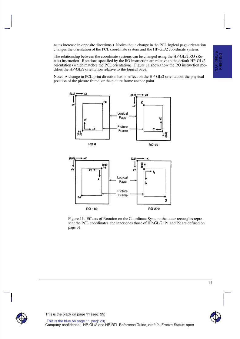
Interactions between Different Coordinate Systems
Landscapeorientation
HP RTLand PCL
HP-GL/2 printers
HP-GL/2 plotters
Portraitorientation
Landscapeorientation
Portraitorientation
Portraitorientation
Landscapeorientation
or
or
Figure 10. HP RTL, PCL, and HP-GL/2 Coordinate Systems; the “orientation” refersto the paper-feed direction
The default PCL and HP RTL coordinate systems are different from the default HP-GL/2 coor-dinate system; furthermore, the default system in HP-GL/2 differs for devices that support theHP-GL/2 Technical Graphics Extension (see page 77; devices termed “ plotters” in Figure 10)and those that do not (“ printers” in Figure 10).
For devices that support the Technical Graphics Extension, the page size is determined by thePS (Plot Size) instruction; for other devices, the page size is the picture frame size importedfrom PCL. In addition, the default origin is at different places, depending on the context (PCL,HP RTL, or HP-GL/2), the device type (“plotter” or “printer”), and the orientation (portrait orlandscape direction of paper feed). The directions of +X and +Y also differ.
The HP-GL/2 coordinate system can be set up to match the PCL and HP RTL coordinate sys-tems; see the examples on pages 37 and 38.
The relationship between the orientation of the HP-GL/2 coordinate system and the PCL orHP RTL coordinate system is important if you are using PCL or HP RTL with HP-GL/2. Thefollowing figure illustrates this relationship for the default HP-GL/2 orientation for “printers”and the PCL logical page orientation. As shown in the illustration, in this HP-GL/2 orientation,the origin of the HP-GL/2 coordinate system defaults to the lower-left corner of the PCL pictureframe. (The HP-GL/2 and PCL X-coordinates increase in the same direction, but the Y-coordi-
8/12/2019 HPGL2-RTL ReferenceGuide 5961-3526 540pages Sep96
http://slidepdf.com/reader/full/hpgl2-rtl-referenceguide-5961-3526-540pages-sep96 29/539
11
This is the black on page 11 (seq: 29)
Company confidential. HP-GL/2 and HP RTL Reference Guide, draft 2. Freeze Status: open
nates increase in opposite directions.) Notice that a change in the PCL logical page orientationchanges the orientation of the PCL coordinate system and the HP-GL/2 coordinate system.
The relationship between the coordinate systems can be changed using the HP-GL/2 RO (Ro-tate) instruction. Rotations specified by the RO instruction are relative to the default HP-GL/2orientation (which matches the PCL orientation). Figure 11 shows how the RO instruction mo-difies the HP-GL/2 orientation relative to the logical page.
Note: A change in PCL print direction has no effect on the HP-GL/2 orientation, the physicalposition of the picture frame, or the picture frame anchor point.
Figure 11. Effects of Rotation on the Coordinate System; the outer rectangles repre-sent the PCL coordinates, the inner ones those of HP-GL/2; P1 and P2 are defined onpage 31
This is the blue on page 11 (seq: 29)
P R I N T I N G
P L O T T I N
G &
8/12/2019 HPGL2-RTL ReferenceGuide 5961-3526 540pages Sep96
http://slidepdf.com/reader/full/hpgl2-rtl-referenceguide-5961-3526-540pages-sep96 30/539
12
This is the black on page 12 (seq: 30)
Company confidential. HP-GL/2 and HP RTL Reference Guide, draft 2. Freeze Status: open
Units of Measure
HP-GL/2, PCL, and HP RTL use different systems for measuring units. See the PCL 5 Refer-ence Guide for information on PCL units of measure.
HP-GL/2 Units of Measure
In HP-GL/2 mode, you can measure along the X,Y axes and express coordinates using twotypes of units: plotter-units and user-units.
One plotter-unit equals 0.025 mm. When you specify distances in plotter-units, the device con-verts the number of plotter-units to equivalent dot coordinates before printing. Under defaultconditions, the device uses plotter-units.
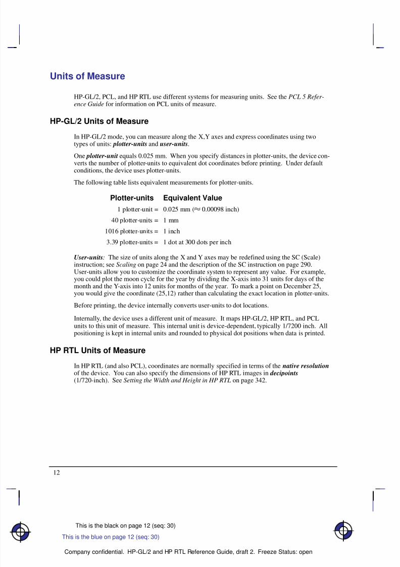
The following table lists equivalent measurements for plotter-units.
Plotter-units Equivalent Value1 plotter-unit = 0.025 mm ( 0.00098 inch)
40 plotter-units = 1 mm
1016 plotter-units = 1 inch
3.39 plotter-units = 1 dot at 300 dots per inch
User-units: The size of units along the X and Y axes may be redefined using the SC (Scale)instruction; see Scaling on page 24 and the description of the SC instruction on page 290.User-units allow you to customize the coordinate system to represent any value. For example,you could plot the moon cycle for the year by dividing the X-axis into 31 units for days of themonth and the Y-axis into 12 units for months of the year. To mark a point on December 25,you would give the coordinate (25,12) rather than calculating the exact location in plotter-units.
Before printing, the device internally converts user-units to dot locations.
Internally, the device uses a different unit of measure. It maps HP-GL/2, HP RTL, and PCLunits to this unit of measure. This internal unit is device-dependent, typically 1/7200 inch. Allpositioning is kept in internal units and rounded to physical dot positions when data is printed.
HP RTL Units of Measure
In HP RTL (and also PCL), coordinates are normally specified in terms of the native resolutionof the device. You can also specify the dimensions of HP RTL images in decipoints(1/720-inch). See Setting the Width and Height in HP RTL on page 342.
This is the blue on page 12 (seq: 30)
8/12/2019 HPGL2-RTL ReferenceGuide 5961-3526 540pages Sep96
http://slidepdf.com/reader/full/hpgl2-rtl-referenceguide-5961-3526-540pages-sep96 31/539

8/12/2019 HPGL2-RTL ReferenceGuide 5961-3526 540pages Sep96
http://slidepdf.com/reader/full/hpgl2-rtl-referenceguide-5961-3526-540pages-sep96 32/539
14
This is the black on page 14 (seq: 32)
Company confidential. HP-GL/2 and HP RTL Reference Guide, draft 2. Freeze Status: open
You can find more details in the descriptions of the HP RTL commands (those beginning ),starting on page 403. The @PJL commands are described on page 394.
HP-GL/2 instructions and HP RTL commands interact with each other. There is a detailed de-scription of the effects of each environment on the other on page 391.
8/12/2019 HPGL2-RTL ReferenceGuide 5961-3526 540pages Sep96
http://slidepdf.com/reader/full/hpgl2-rtl-referenceguide-5961-3526-540pages-sep96 33/539
15
This is the black on page 15 (seq: 33)
Company confidential. HP-GL/2 and HP RTL Reference Guide, draft 2. Freeze Status: open
PART 2: HP-GL/2
This Part contains the following sections:
An alphabetical list of all the HP-GL/2 instructions.
This is the blue on page 15 (seq: 33)

8/12/2019 HPGL2-RTL ReferenceGuide 5961-3526 540pages Sep96
http://slidepdf.com/reader/full/hpgl2-rtl-referenceguide-5961-3526-540pages-sep96 34/539
16
This is the black on page 16 (seq: 34)
Company confidential. HP-GL/2 and HP RTL Reference Guide, draft 2. Freeze Status: open
8/12/2019 HPGL2-RTL ReferenceGuide 5961-3526 540pages Sep96
http://slidepdf.com/reader/full/hpgl2-rtl-referenceguide-5961-3526-540pages-sep96 35/539
17
This is the black on page 17 (seq: 35)
Company confidential. HP-GL/2 and HP RTL Reference Guide, draft 2. Freeze Status: open
Chapter 2: Introduction to HP-GL/2
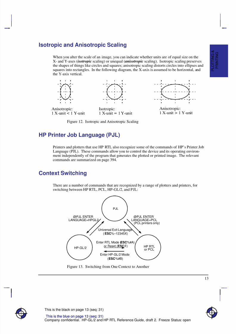
HP-GL/2 is the standardized version of the Hewlett-Packard Graphics Language. It is designedto provide a set of consistent functions across a wide range of peripheral devices, both plottersand printers. Its aim is therefore to reduce programming effort and the future compatibility of your programs, while allowing great flexibility in creating images.
This chapter describes the principles of HP-GL/2 and introduces the following topics:
The Instruction Groups—the Kernel and the Extensions.
Pen Status and Location.
Scaling.
HP-GL/2 Instructions and Syntax.
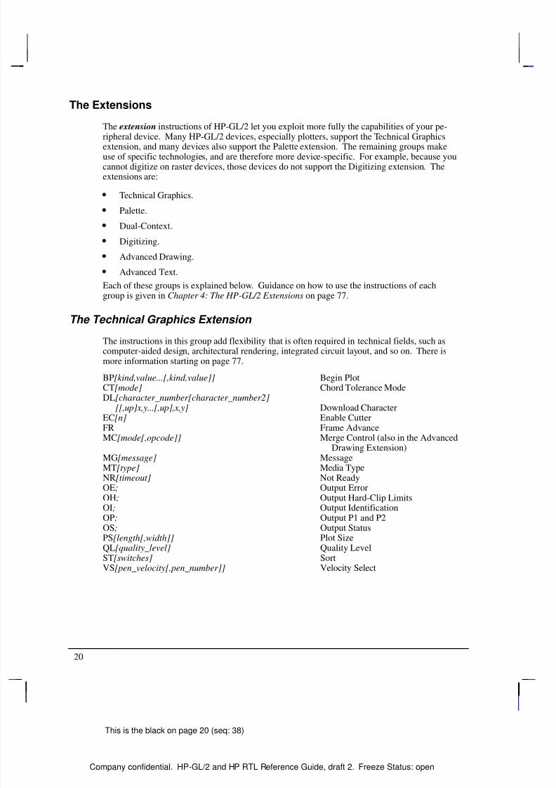
HP-GL/2 consists of a kernel set of instructions that are supported on all HP-GL/2 devices. Inaddition, there are sets of extensions that allow you to make full use of the functions of particu-lar types of device. These extension instructions are not supported on all HP-GL/2 devices.
In addition to using the instructions of HP-GL/2, you may also want to use the commands of the PCL Printer Language or of the HP Raster Transfer Language (HP RTL).
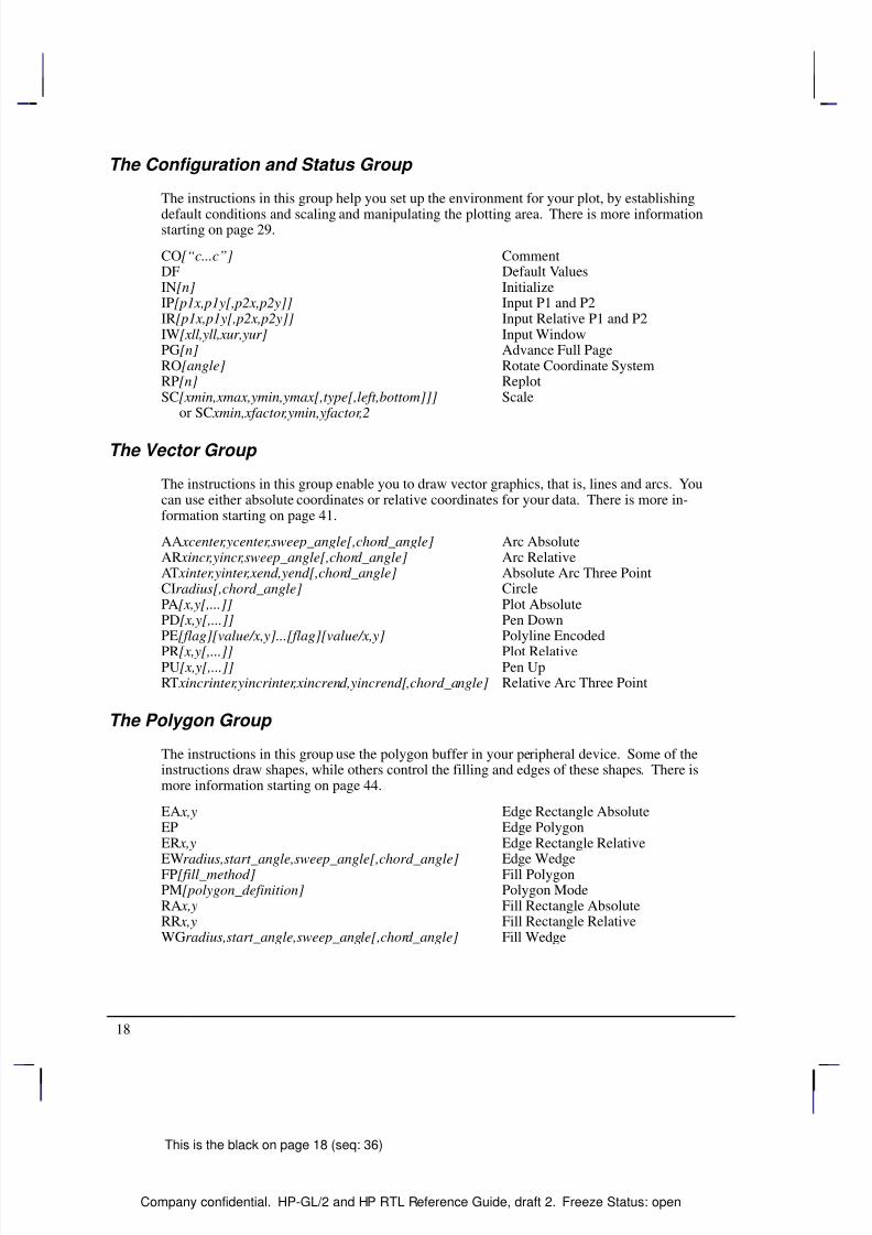
The Instruction Groups
HP-GL/2 is made up of a core set of instructions (called the HP-GL/2 kernel ) and several ex- tensions. All HP-GL/2 devices support the kernel instructions. The extensions (see page 20)help you to make use of special technologies or device capabilities. Many plotters support theTechnical Graphics Extension; many devices also support the Palette Extension. The remainingextensions make use of specific technologies and are, therefore, device-specific.
The Kernel
The kernel is the foundation of HP-GL/2 and contains most of the instructions. All HP-GL/2devices support the kernel instructions. The kernel consists of five functional groups:
Configuration and Status.
Vector.
Polygon.
Line and Fill Attributes.
Character.
Each of these groups is explained below. Guidance on how to use the instructions of eachgroup is given in Chapter 3: The HP-GL/2 Kernel on page 29.
This is the blue on page 17 (seq: 35)
I N T R O D U C T I O N
H P - G L / 2
8/12/2019 HPGL2-RTL ReferenceGuide 5961-3526 540pages Sep96
http://slidepdf.com/reader/full/hpgl2-rtl-referenceguide-5961-3526-540pages-sep96 36/539
8/12/2019 HPGL2-RTL ReferenceGuide 5961-3526 540pages Sep96
http://slidepdf.com/reader/full/hpgl2-rtl-referenceguide-5961-3526-540pages-sep96 37/539
19
This is the black on page 19 (seq: 37)
Company confidential. HP-GL/2 and HP RTL Reference Guide, draft 2. Freeze Status: open
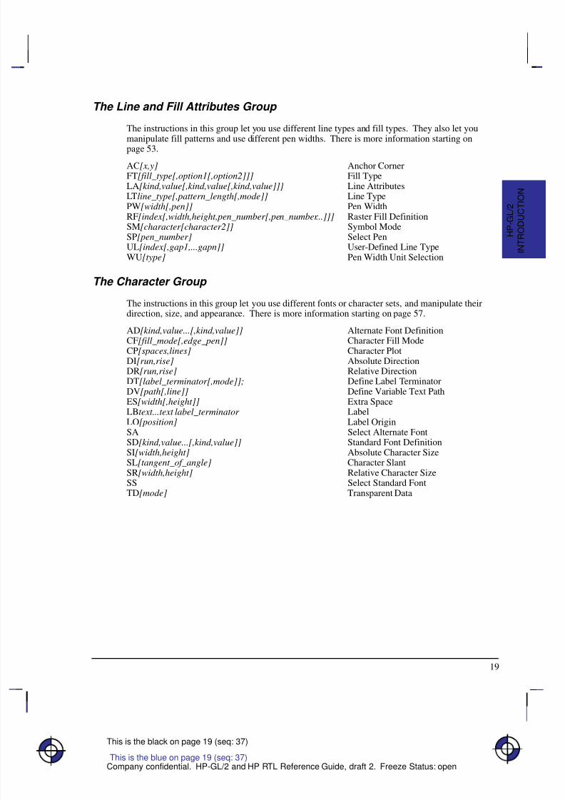
The Line and Fill Attributes Group
The instructions in this group let you use different line types and fill types. They also let you
manipulate fill patterns and use different pen widths. There is more information starting onpage 53.
AC[x,y] Anchor CornerFT[fill_type[,option1[,option2]]] Fill TypeLA[kind,value[,kind,value[,kind,value]]] Line AttributesLTline_type[,pattern_length[,mode]] Line TypePW[width[,pen]] Pen WidthRF[index[,width,height,pen_number[,pen_number...]]] Raster Fill DefinitionSM[character[character2]] Symbol ModeSP[pen_number] Select PenUL[index[,gap1,...gapn]] User-Defined Line TypeWU[type] Pen Width Unit Selection
The Character Group
The instructions in this group let you use different fonts or character sets, and manipulate theirdirection, size, and appearance. There is more information starting on page 57.
AD[kind,value...[,kind,value]] Alternate Font DefinitionCF[fill_mode[,edge_pen]] Character Fill ModeCP[spaces,lines] Character PlotDI[run,rise] Absolute DirectionDR[run,rise] Relative DirectionDT[label_terminator[,mode]]; Define Label TerminatorDV[path[,line]] Define Variable Text PathES[width[,height]] Extra SpaceLBtext...text label_terminator Label
LO[position] Label OriginSA Select Alternate FontSD[kind,value...[,kind,value]] Standard Font DefinitionSI[width,height] Absolute Character SizeSL[tangent_of_angle] Character SlantSR[width,height] Relative Character SizeSS Select Standard FontTD[mode] Transparent Data
This is the blue on page 19 (seq: 37)
I N T R O D U C T I O N
H P - G L / 2
8/12/2019 HPGL2-RTL ReferenceGuide 5961-3526 540pages Sep96
http://slidepdf.com/reader/full/hpgl2-rtl-referenceguide-5961-3526-540pages-sep96 38/539
8/12/2019 HPGL2-RTL ReferenceGuide 5961-3526 540pages Sep96
http://slidepdf.com/reader/full/hpgl2-rtl-referenceguide-5961-3526-540pages-sep96 39/539
21
This is the black on page 21 (seq: 39)
Company confidential. HP-GL/2 and HP RTL Reference Guide, draft 2. Freeze Status: open
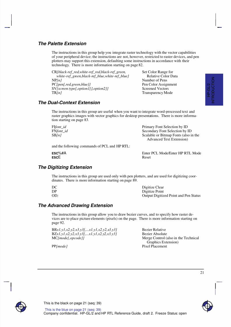
The Palette Extension
The instructions in this group help you integrate raster technology with the vector capabilities
of your peripheral device; the instructions are not, however, restricted to raster devices, and penplotters may support this extension, defaulting some instructions in accordance with theirtechnology. There is more information starting on page 82.
CR[black-ref_red,white-ref_red,black-ref_green, Set Color Range for white-ref_green,black-ref_blue,white-ref_blue] Relative Color DataNP[n] Number of PensPC[pen[,red,green,blue]] Pen Color AssignmentSV[screen type[,option1[],option2]] Screened VectorsTR[n] Transparency Mode
The Dual-Context Extension
The instructions in this group are useful when you want to integrate word-processed text and
raster graphics images with vector graphics for desktop presentations. There is more informa-tion starting on page 83.
FI font_id Primary Font Selection by IDFN font_id Secondary Font Selection by IDSB[n] Scalable or Bitmap Fonts (also in the
Advanced Text Extension)
and the following commands of PCL and HP RTL:
%#A Enter PCL Mode/Enter HP RTL ModeE Reset
The Digitizing Extension
The instructions in this group are used only with pen plotters, and are used for digitizing coor-dinates. There is more information starting on page 89.
DC Digitize ClearDP Digitize PointOD; Output Digitized Point and Pen Status
The Advanced Drawing Extension
The instructions in this group allow you to draw bezier curves, and to specify how raster de-vices are to place picture elements (pixels) on the page. There is more information starting onpage 92.
BR x1,y1,x2,y2,x3,y3[,...x1,y1,x2,y2,x3,y3] Bezier RelativeBZ x1,y1,x2,y2,x3,y3[,...x1,y1,x2,y2,x3,y3] Bezier AbsoluteMC[mode[,opcode]] Merge Control (also in the Technical
Graphics Extension)PP[mode] Pixel Placement
I N T R O D U C T I O N
H P - G L / 2
This is the blue on page 21 (seq: 39)
8/12/2019 HPGL2-RTL ReferenceGuide 5961-3526 540pages Sep96
http://slidepdf.com/reader/full/hpgl2-rtl-referenceguide-5961-3526-540pages-sep96 40/539
22
This is the black on page 22 (seq: 40)
Company confidential. HP-GL/2 and HP RTL Reference Guide, draft 2. Freeze Status: open
The Advanced Text Extension
The instruction that forms this group allows you to use either 8-bit or 16-bit character sets.
There is more information starting on page 94.
LM[mode[,row_number]] Label ModeSB[n] Scalable or Bitmap Fonts (also in the
Dual-Context Extension)
Pen Status and Location
Since printing vector graphics has traditionally been performed with pen plotters, the terms penand pen location (or pen position) are used to described the cursor in HP-GL/2 mode, and thecurrent active position (CAP) in HP RTL or PCL mode. Whether the pen is logical (for rasterdevices) or physical (for pen plotters), it must be selected in order to print. Instructions such as
PU (Pen Up) or PD (Pen Down), and phrases such as “current pen position” or “moving thepen” apply to the imaginary pen just as they do a physical pen on a pen plotter.
Pen Status
Pen status refers to whether the “pen” is up or down. Use the PU (Pen Up) instruction with X,Ycoordinates to move the pen to the desired printing location without drawing a line. Use the PD(Pen Down) instruction with X,Y coordinates to lower the pen and begin drawing from the cur-rent location to the first specified X,Y coordinate.
When you enter HP-GL/2 mode for the first time following a Reset (E) command, no penhas been selected and the pen is up. This means that no lines are drawn when HP-GL/2 instruc-tions are given until a pen is selected. This can be done using the SP (Select Pen) instruction.
Most drawing instructions require that the pen be lowered to produce marks on the page. Oncelowered with a PD instruction, the pen remains down for subsequent HP-GL/2 printing instruc-tions until a PU or IN (Initialize) instruction is issued. The pen remains selected until a new SPinstruction is received. You must be aware of the pen’s up/down status to avoid drawing straylines between parts of your picture.
Note: Upon entry into HP-GL/2 mode, a good programming practice is to select a pen and is-sue a pen-up move to the initial starting position. This ensures that a pen is selected and is inthe proper position to begin drawing.
Whenever the device receives a PD instruction, it produces a dot at the current pen loca-tion. If the pen is already down when the device receives an instruction with an automaticpen down, the unnecessary dot can mar your final output. For best results, include a PUinstruction before any instruction with an automatic pen down.
Only the portion of the pen falling within the effective window is printed. The pen iscentered on a line between the beginning and end points, with half of the pen width fallingon either side of this line.
The definition of each instruction tells you whether it has an automatic pen down. If youfind that part of your image is not drawn, make sure your instruction sequence uses the PDinstruction before the affected instructions.
This is the blue on page 22 (seq: 40)
8/12/2019 HPGL2-RTL ReferenceGuide 5961-3526 540pages Sep96
http://slidepdf.com/reader/full/hpgl2-rtl-referenceguide-5961-3526-540pages-sep96 41/539
23
This is the black on page 23 (seq: 41)
Company confidential. HP-GL/2 and HP RTL Reference Guide, draft 2. Freeze Status: open
Instructions that Include an Automatic Pen-Down Movement
Every time you use a PU or PD instruction, the device updates the pen up/down status. The
following instructions include an automatic PD instruction as part of their function. After per-forming their complete function, they return the pen to its previous up/down state.
CI CircleEA Edge Rectangle AbsoluteEP Edge PolygonER Edge Rectangle RelativeEW Edge WedgeFP Fill PolygonLB LabelPE Polyline Encoded (using a flag)RA Fill Rectangle AbsoluteRR Fill Rectangle RelativeSM Symbol Mode
WG Fill Wedge
Pen Location
Pen location refers to the X,Y coordinates of the pen. Most instructions, when completed, up-date the pen location. The next instruction then begins at that location. Some instructions donot update the current pen location. The definition of each instruction tells you whether thecurrent pen location is updated or restored. Use the PU (Pen Up) instruction with the desiredX,Y coordinates to lift the pen and move it to a new location.
The DF (Default Values) instruction does not reset the current pen location; the IN (Initialize)instruction moves it to the origin of the hard-clip limits. You should specify your beginningpen location for each HP-GL/2 drawing.
“ Lost” Mode
Parameter values less than the range maximum are passed by the parser; these values may sub-sequently be unscaled into device-dependent internal resolution units (for example, 7 200 or9 600 units-per-inch) that exceed the device-dependent internally representable number range.If this occurs, the device enters a “lost” mode; all relative drawing instructions are ignored untila instruction is received which specifies an absolute move to a point within the internally repre-sentable number range.
When “lost” mode is entered, the pen is raised and the following instructions are ignored: AA,AR, AT, CI, CP, EA, ER, EW, LB, PE, PM, PR, RA, RR, RT, and WG.
The instructions allowed in “lost” mode are: AC, AD, CF, CO, DF, DI, DR, DT, DV, ES, FT,IN, IP, IR, IW, LA, LO, LT, PA, PD, PG, PU, PW, RF, RO, RP, SA, SB, SC, SD, SI, SL, SM,
SP, SR, SS, TD, UL, WU, and the PM1/PM2 forms of PM.
The instructions IN, PG, RP, and PA, with in-range parameters, clear “lost” mode; PD and PUin absolute plotting mode, with in-range parameters, also clear “lost” mode. When PD clears“lost” mode, a line is drawn from the last valid current position to the first point in the PD pa-rameter sequence. If PA clears “lost” mode, the pen will not go down until a PD instruction isreceived.
I N T R O D U C T I O N
H P - G L / 2
This is the blue on page 23 (seq: 41)
8/12/2019 HPGL2-RTL ReferenceGuide 5961-3526 540pages Sep96
http://slidepdf.com/reader/full/hpgl2-rtl-referenceguide-5961-3526-540pages-sep96 42/539
24
This is the black on page 24 (seq: 42)
Company confidential. HP-GL/2 and HP RTL Reference Guide, draft 2. Freeze Status: open
When “lost” in polygon mode, “PM2” clears “lost” mode, closes the current polygon using thecurrent pen state, and restores the original pen position and up/down state. “PM1” does notclear “lost” mode, but it does close the current subpolygon using the current pen up/down state
if the starting vertex is valid. The buffer then contains:the valid points up to, but not including the point that set “lost” mode;the points after “lost” mode is cleared;and the closure point.
Points stored after “lost” mode is cleared are stored as pen-up points until a PD instruction isreceived.
When “lost” mode is entered while drawing an arc or a wedge, only the valid arc segments thatwere generated before the arc segment that caused the device to be “lost” are drawn. If a rect-angle instruction (EA, ER, RA, or RR) contains parameters that would make the device enter“lost” mode, error 3 (invalid parameter) is set and the instruction is ignored.
Scaling
When you scale a drawing, you define your own units of measurement instead of using plotter-units; the device converts your units (user-units) to dot positions for placing the image on thepage. Scaling allows control of the device using units that are easy for you to work with.
For example, you can scale your drawing to divide the drawing area into 100 squares. As youplan the drawing, you can think in terms of 100 squares rather than plotter-units. Another ex-ample of scaling is that since 400 plotter-units equals 1 centimeter, you can establish this scaleto print in user-units equal to 1 centimeter each.
Scaling begins with the scaling points, P1 and P2 (see The Scaling Points, P1 and P2 on page31). P1 and P2 act as two points marking opposite corners of a rectangle. You can make thisrectangle any size and place it anywhere in relation to the origin, depending on the plotter-unit
coordinates you specify for P1 and P2. (P1 and P2 default to opposite corners of the hard-cliplimits, but you can change their locations using the Input P1 and P2 [IP] or Input Relative P1and P2 [IR] instructions). P1 is also the default origin (0,0) for the coordinate system.
After you have defined the positions for P1 and P2, or have accepted the default, use this imagi-nary rectangle to set up scaling for your drawing. With the SC (Scale) instruction you specifyhow many sections the rectangle divides into horizontally (the X-axis) and how many sectionsthe rectangle divides into vertically (the Y-axis). In this way you create your user-units.
Scaling also allows you to enlarge or reduce your image by changing the locations of P1 andP2. P1 and P2 represent physical locations in relation to the hard-clip limits. When the imagi-nary rectangle formed by P1 and P2 is enlarged or reduced with the IP or IR instructions, theHP-GL/2 image is also enlarged or reduced to fit the new P1/P2 rectangle. (For a more detailedexplanation of scaling and the Scale (SC) instruction, see page 290.)
For importing existing HP-GL/2 images, another method of enlarging or reducing drawingsexists. It involves varying the size of the hard-clip limits and is described in Absolute and Rel-ative Pen Movement on page 8. This method allows you to scale an image while maintainingthe aspect ratio of all elements (including fonts). The Scale instruction does not affect the sizeof fonts.
This is the blue on page 24 (seq: 42)
8/12/2019 HPGL2-RTL ReferenceGuide 5961-3526 540pages Sep96
http://slidepdf.com/reader/full/hpgl2-rtl-referenceguide-5961-3526-540pages-sep96 43/539
25
This is the black on page 25 (seq: 43)
Company confidential. HP-GL/2 and HP RTL Reference Guide, draft 2. Freeze Status: open
HP-GL/2 Syntax
The following illustration shows a typical HP-GL/2 instruction and the description of its com-ponents.
Each HP-GL/2 instruction consists of up to four parts:
A two-character mnemonic which defines the function of the instruction. It can be upper-case or lowercase. For example, IN is the Initialize instruction, SP is the Select Peninstruction, and CI is the Circle instruction.
Parameters are used with certain HP-GL/2 instructions to tell the device to complete theinstruction in a particular way. Some instructions have no parameters, some have requiredparameters. and some have optional parameters. Some instructions have additional param-eters that further qualify other parameters.
Separators which separate one parameter from the next. You are recommended to use acomma as a separator, though you can use spaces. However, in some computer systems,spaces are automatically removed before being sent to the peripheral device. If the secondof a pair of parameters starts with a plus or minus sign, this is also interpreted as a separa-tor for numeric parameters. Separators are not used with the DT, LB, PE, and SMinstructions.
A terminator which separates one instruction from the next. The recommended way of separating instructions is by using no explicit terminator, that is, the mnemonic for the next
instruction constitutes the separator from the previous. Most instructions can also beterminated with a semicolon, though dropping the semicolon will reduce the amount of data transmitted to the device by about 10%. Some instructions (for example, PG, PE, andall output instructions) must be terminated with a semicolon. The LB instruction, de-scribed on page 206, requires a special terminator set by the DT (Define Label Terminator)instruction (see page 154). We recommend you place a semicolon at the end of the lastinstruction in your program to terminate the instruction and ensure the proper completionof your program.
In the example above, “PA” is the mnemonic, “30” and “30” are its two parameters, “,” is aseparator, and “;” is the terminator.
The following illustration shows the flexibility of the syntax. Each variation of the two-instruc-tion sequence is permissible; however, the first method is recommended—using the first letterof the next mnemonic to terminate instructions, using no spaces between parameters, and sepa-
rating parameters with a comma. This method sends fewer bytes to the device, therebyreducing transmission times.
This is the blue on page 25 (seq: 43)
I N T R O D U C T I O N
H P - G L / 2
8/12/2019 HPGL2-RTL ReferenceGuide 5961-3526 540pages Sep96
http://slidepdf.com/reader/full/hpgl2-rtl-referenceguide-5961-3526-540pages-sep96 44/539
26
This is the black on page 26 (seq: 44)
Company confidential. HP-GL/2 and HP RTL Reference Guide, draft 2. Freeze Status: open
The program examples used in this book are spaced out so that the function of each instructioncan be clearly seen. It is not recommended to arrange your instructions in this manner. In par-ticular, do not leave any spaces between the DT and LB instructions and their parameters.
Notation Used in this Book to Present Instruction Syntax
The following notation is used in the descriptions of instruction syntax in this book:
MN Instruction mnemonic, always two uppercase characters.
parameters All parameters are shown in italics. A comma is always shown asthe separator between parameters. A space, “+”, or “–” is alsovalid, although not preferred. (A “+” or “–” is a valid separatoronly for numeric parameters.)
[ ] Parameters in square brackets are optional; you must have an evennumber of X,Y coordinates.
[,...] Any number of the previous parameter; you must have an evennumber of X,Y coordinates.
; Instruction terminator. A semicolon is normally optional and isshown in square brackets in most instruction syntaxes. Although asemicolon is always shown in instruction syntaxes, any non-nu-meric character is also valid.
Three exceptions to the optional use of the semicolon as aninstruction terminator occur in the following instructions: PE (Po-lyline Encoded), LB (Label), and CO (Comment). PE and PG(Advance Full Page) must be terminated by a semicolon. LB isterminated by the non-printing end-of-text character ( —deci-mal 3), or a user-defined character. The comment string of theCO instruction must be delimited by double quotes.
A semicolon terminator is always required following the lastinstruction prior to leaving HP-GL/2 mode.
Labels require a special terminator, usually the ASCII end-of-text( ) character (decimal code 3). See the descriptions of the LBand DT instructions.
Note that although X,Y coordinates are normally shown in parentheses in text—for example,(3,4) or (0,0)—the parentheses are not part of the syntax and must not be entered in yourinstructions.
Omitting Optional Parameters
Some instructions have optional parameters that take on default values if they are omitted.When you omit a parameter, you must omit all subsequent parameters in the same instruc-tion—the DT (Define Label Terminator) instruction is an exception.
For example, the LT (Line Type) instruction has three optional parameters: line_type, pat-tern_length, and mode. The following instruction shows all three being used (line_type = 6,
pattern_length = 25, mode = 1).
LT 6,25,1;
If you omit the second parameter you must also omit the third parameter, as shown below:
LT 6;
8/12/2019 HPGL2-RTL ReferenceGuide 5961-3526 540pages Sep96
http://slidepdf.com/reader/full/hpgl2-rtl-referenceguide-5961-3526-540pages-sep96 45/539
8/12/2019 HPGL2-RTL ReferenceGuide 5961-3526 540pages Sep96
http://slidepdf.com/reader/full/hpgl2-rtl-referenceguide-5961-3526-540pages-sep96 46/539
8/12/2019 HPGL2-RTL ReferenceGuide 5961-3526 540pages Sep96
http://slidepdf.com/reader/full/hpgl2-rtl-referenceguide-5961-3526-540pages-sep96 47/539
8/12/2019 HPGL2-RTL ReferenceGuide 5961-3526 540pages Sep96
http://slidepdf.com/reader/full/hpgl2-rtl-referenceguide-5961-3526-540pages-sep96 48/539
30
This is the black on page 30 (seq: 48)
Company confidential. HP-GL/2 and HP RTL Reference Guide, draft 2. Freeze Status: open
Á Á Á Á Á Á Á Á Á
Á Á Á Á Á Á Á Á Á
PG Advance Full PageÁ Á Á Á Á Á Á Á Á Á Á Á Á Á Á Á Á Á
Á
Á Á Á Á Á Á Á Á Á Á Á Á Á Á Á Á Á
Terminates the plot and advances the page (see note).Á Á Á Á Á Á Á Á Á
Á Á Á Á Á Á Á Á Á
Á Á Á Á Á Á Á Á Á
RO Rotate CoordinateSystem
Á Á Á Á Á Á Á Á Á Á Á Á Á Á Á Á Á Á
Á Á Á Á Á Á Á Á Á Á Á Á Á Á Á Á Á Á
Á Á Á Á Á Á Á Á Á Á Á Á Á Á Á Á Á Á
Rotates the HP-GL/2 coordinate system.
Á Á Á Á Á Á Á Á Á
Á Á Á Á Á Á Á Á Á
RP Replot Á Á Á Á Á Á Á Á Á Á Á Á Á Á Á Á Á Á
Á Á Á Á Á Á Á Á Á Á Á Á Á Á Á Á Á Á
Plots multiple copies of a stored plot (see note).
Á Á Á Á Á Á Á Á Á
Á Á Á Á Á Á Á Á Á
SC Scale Á Á Á Á Á Á Á Á Á Á Á Á Á Á Á Á Á Á
Á Á Á Á Á Á Á Á Á Á Á Á Á Á Á Á Á Á
Establishes a user-unit coordinate system.
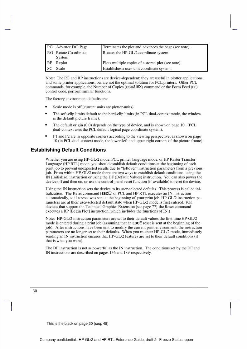
Note: The PG and RP instructions are device-dependent; they are useful in plotter applicationsand some printer applications, but are not the optimal solution for PCL printers. Other PCLcommands, for example, the Number of Copies (&l#X) command or the Form Feed ()control code, perform similar functions.
The factory environment defaults are:
Scale mode is off (current units are plotter-units).
The soft-clip limits default to the hard-clip limits (in PCL dual-context mode, the windowis the default picture frame).
The default origin (0,0) depends on the type of device, and is shown on page 10. (PCLdual-context uses the PCL default logical page coordinate system).
P1 and P2 are in opposite corners according to the viewing perspective, as shown on page10 (in PCL dual-context mode, the lower-left and upper-right corners of the picture frame).
Establishing Default Conditions
Whether you are using HP-GL/2 mode, PCL printer language mode, or HP Raster TransferLanguage (HP RTL) mode, you should establish default conditions at the beginning of eachprint job to prevent unexpected results due to “leftover” instruction parameters from a previous
job. From within HP-GL/2 mode there are two ways to establish default conditions: using theIN (Initialize) instruction or using the DF (Default Values) instruction. You can also power the
device off and then on, or use the control-panel reset function (if available) to reset the device.Using the IN instruction sets the device to its user-selected defaults. This process is called ini-tialization. The Reset command (E) of PCL and HP RTL executes an IN instructionautomatically, so if a reset was sent at the beginning of your print job, HP-GL/2 instruction pa-rameters are at their user-selected default state when HP-GL/2 mode is first entered. (Ondevices that support the Technical Graphics Extension [see page 77] the Reset commandexecutes a BP [Begin Plot] instruction, which includes the functions of IN.)
Note: HP-GL/2 instruction parameters are set to their default values the first time HP-GL/2mode is entered during a print job (assuming that an E reset is sent at the beginning of the
job). After instructions have been sent to modify the current print environment, the instructionparameters are no longer set to their defaults. When you re-enter HP-GL/2 mode, immediatelysending an IN instruction ensures that HP-GL/2 features are set to their default conditions (if that is what you want).
The DF instruction is not as powerful as the IN instruction. The conditions set by the DF andIN instructions are described on pages 136 and 189 respectively.
8/12/2019 HPGL2-RTL ReferenceGuide 5961-3526 540pages Sep96
http://slidepdf.com/reader/full/hpgl2-rtl-referenceguide-5961-3526-540pages-sep96 49/539
31
This is the black on page 31 (seq: 49)
Company confidential. HP-GL/2 and HP RTL Reference Guide, draft 2. Freeze Status: open
The Scaling Points, P1 and P2
When you scale a drawing, you define your own units of measurement, which the device then
converts to plotter-units. Scaling relies on the relationship between two points P1 and P2.These two points are called the scaling points because they take on the user-unit values thatyou specify with the SC (Scale) instruction. You can change the locations of P1 and P2 usingeither the IP (Input P1 and P2), or IR (Input Relative P1 and P2) instruction.
P1 and P2 always represent an absolute location, defined in plotter-units. They designate oppo-site corners of a rectangular printing area. The P1/P2 rectangular area is not a graphics limit;plotting is not restricted to the P1/P2 area. You can change the size of the rectangular printingarea and move it anywhere within the hard-clip limits, or even outside these limits, dependingon the plotter-unit coordinates you specify using the IP or IR instructions. The biggest benefitof scaling is that your plot will normally retain the same relative proportions on any size of me-dia, except when you use IP with parameters or IR.
If the SC (Scale) instruction is not used, that is scale mode is “off”, all HP-GL/2 measurementsare in fixed plotter-units (0.025 mm).
Using the Scale Instruction
Scaling allows you to establish units of measure with which you are familiar, or which are morelogical to your drawing. The SC (Scale) instruction determines the number of user-units alongthe X- and Y-axes between P1 and P2. The actual size of the units depends on the locations of P1 and P2 and the range of user-units set up by the SC instruction.
There are three types of scaling:
Anisotropic scaling indicates that the size of the units along the X-axis may be differentfrom the size of the units on the Y-axis.
Isotropic scaling indicates that the units are the same size on both axes.
Point-factor scaling sets up a ratio of plotter-units to user-units.
The Scale instruction does not change the locations of P1 and P2, only their coordinate values.Also, scaling is not limited to the rectangular area defined by P1 and P2, but extends across theentire plotting range.
For example, to divide the X-axis into 12 units representing months, and the Y-axis into 10units representing currency values, specify the X-axis to scale from 0 to 12, and the Y-axis toscale from 0 to 10. P1 becomes the origin with user-unit coordinate (0,0) and P2 becomes(12,10). The entire plotting area is now divided into the desired units. Subsequent plottinginstructions use these units. If you tell the device to move to the point (3,4), it moves to thelocation equivalent to (3,4) user-units, not (3,4) plotter-units.
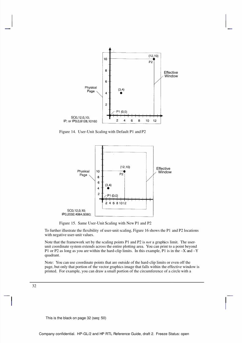
If you move the locations of P1 and P2, the size of the user-units changes. Assume that the
previous illustration showed P1 and P2 in their default locations (the lower-left and upper-rightcorners, respectively, of the hard-clip limits for PCL printers). In Figure 15, P1 and P2 have thesame user-unit values (set with the Scale instruction, SC), but their physical locations havebeen changed, using the IP (Input P1 and P2) instruction. Note that the size of the user-unitshas decreased.
This is the blue on page 31 (seq: 49)
K E R N E L
H P - G L / 2
8/12/2019 HPGL2-RTL ReferenceGuide 5961-3526 540pages Sep96
http://slidepdf.com/reader/full/hpgl2-rtl-referenceguide-5961-3526-540pages-sep96 50/539
32
This is the black on page 32 (seq: 50)
Company confidential. HP-GL/2 and HP RTL Reference Guide, draft 2. Freeze Status: open
Figure 14. User-Unit Scaling with Default P1 and P2
Figure 15. Same User-Unit Scaling with New P1 and P2
To further illustrate the flexibility of user-unit scaling, Figure 16 shows the P1 and P2 locationswith negative user-unit values.
Note that the framework set by the scaling points P1 and P2 is not a graphics limit. The user-unit coordinate system extends across the entire plotting area. You can print to a point beyondP1 or P2 as long as you are within the hard-clip limits. In this example, P1 is in the –X and –Yquadrant.
Note: You can use coordinate points that are outside of the hard-clip limits or even off thepage, but only that portion of the vector graphics image that falls within the effective window isprinted. For example, you can draw a small portion of the circumference of a circle with a
8/12/2019 HPGL2-RTL ReferenceGuide 5961-3526 540pages Sep96
http://slidepdf.com/reader/full/hpgl2-rtl-referenceguide-5961-3526-540pages-sep96 51/539
33
This is the black on page 33 (seq: 51)
Company confidential. HP-GL/2 and HP RTL Reference Guide, draft 2. Freeze Status: open
5-foot radius by moving the pen 5 feet from the page and issuing a CI instruction specifying a5-foot radius; only the portion of the arc that falls within the effective window is printed.
Refer to the SC (Scale) instruction on page 290 for more information on scaling drawings.
Figure 16. New P1 and P2 User-Unit Scaling with Negative Values
Using Scaling Effectively
The following sections describe how to combine scaling and P1/P2 concepts to do the follow-ing.
Enlarge or reduce the size of a drawing.
Draw equal-sized pictures on the same page.
Create mirror-imaged pictures.
Enlarging or Reducing a Picture
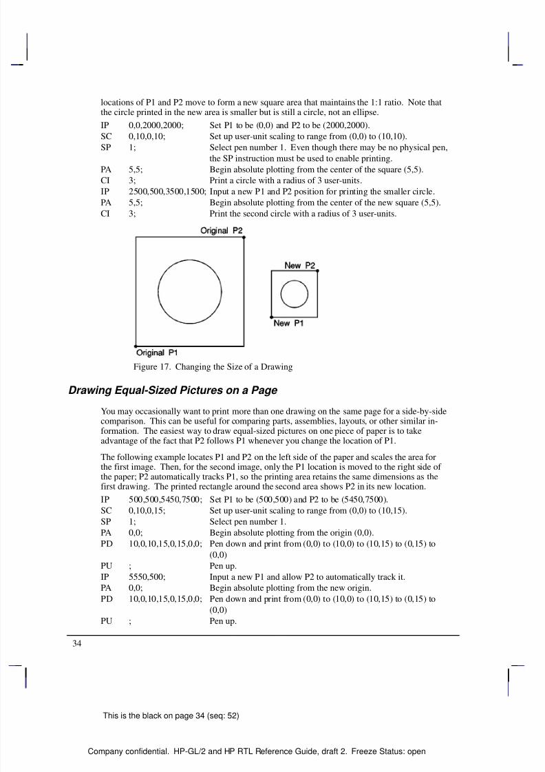
The basic technique for changing a picture’s size is to scale the printing area defined by P1 andP2, and then move the locations of P1 and P2 to define a smaller or larger area. This is espe-cially useful when you want to print the picture on any portion of the page.
Note: Only scaled drawings (those using the SC instruction) are enlarged or reduced when theP1/P2 locations change. Use PCL picture frame scaling when you import into PCL HP-GL/2images created without the SC instruction.
To maintain the proportions of scaled plots, set P1 and P2 to define an area with the same as-pect ratio as the original scaling rectangle. For example, if the area defined by P1 and P2 is3000 x 2000 plotter-units, its aspect ratio is 3:2. To enlarge the plot, set P1 and P2 to define alarger area that maintains a 3:2 ratio.
The following example illustrates this technique using a square (isotropic) P1/P2 scaling rectan-gle with a scale of 0 to 10 for both axes. After drawing a circle within the scaled area, the
This is the blue on page 33 (seq: 51)
K E R N E L
H P - G L / 2
8/12/2019 HPGL2-RTL ReferenceGuide 5961-3526 540pages Sep96
http://slidepdf.com/reader/full/hpgl2-rtl-referenceguide-5961-3526-540pages-sep96 52/539
8/12/2019 HPGL2-RTL ReferenceGuide 5961-3526 540pages Sep96
http://slidepdf.com/reader/full/hpgl2-rtl-referenceguide-5961-3526-540pages-sep96 53/539
35
This is the black on page 35 (seq: 53)
Company confidential. HP-GL/2 and HP RTL Reference Guide, draft 2. Freeze Status: open
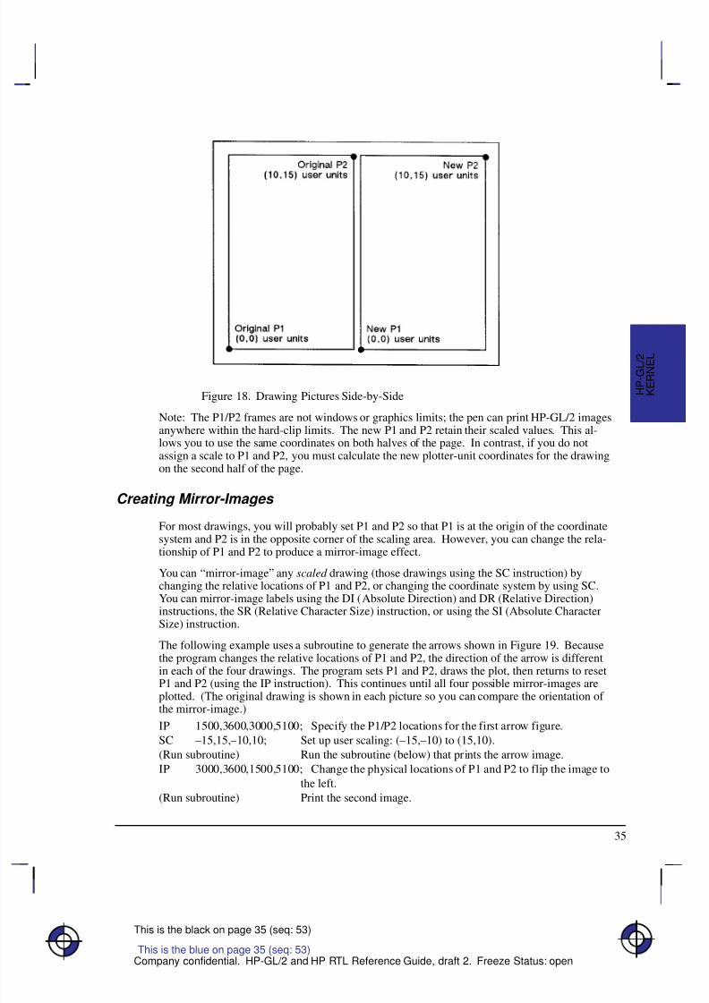
Figure 18. Drawing Pictures Side-by-Side
Note: The P1/P2 frames are not windows or graphics limits; the pen can print HP-GL/2 imagesanywhere within the hard-clip limits. The new P1 and P2 retain their scaled values. This al-lows you to use the same coordinates on both halves of the page. In contrast, if you do notassign a scale to P1 and P2, you must calculate the new plotter-unit coordinates for the drawingon the second half of the page.
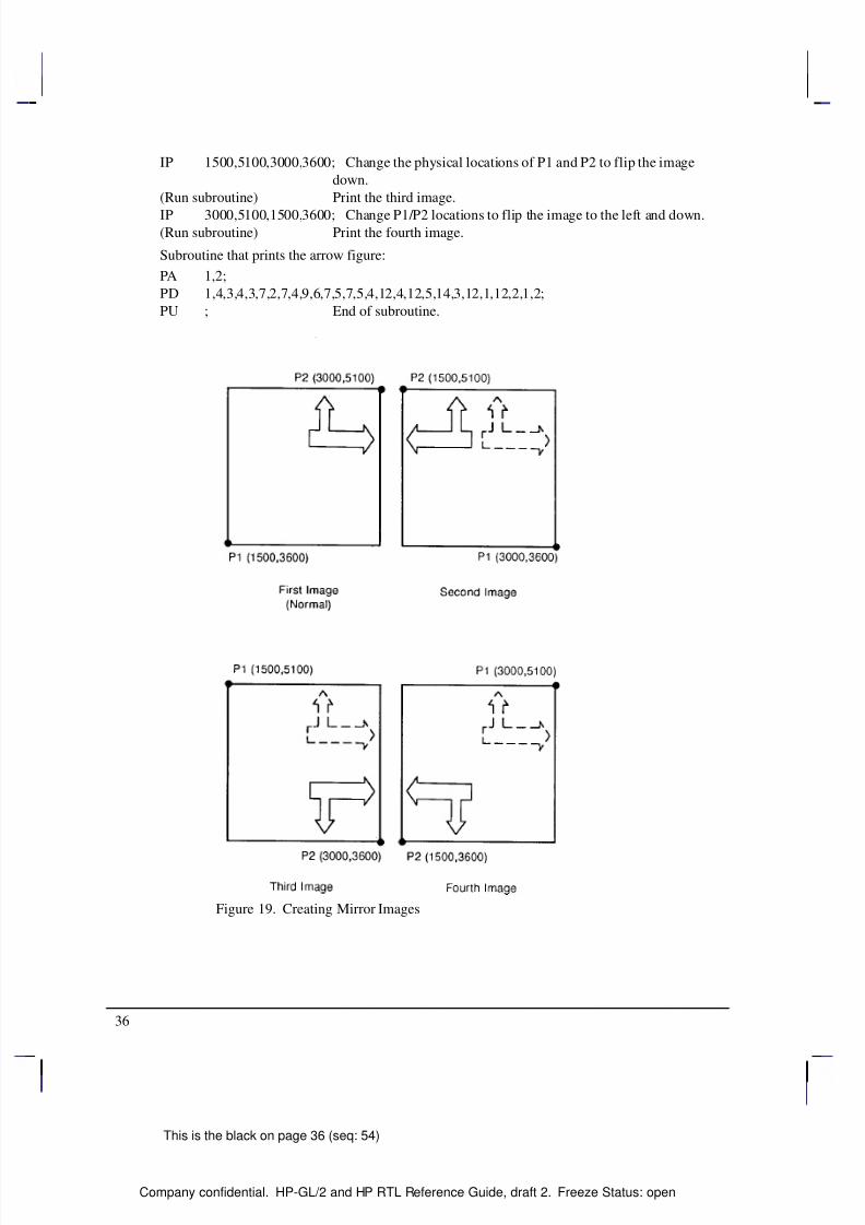
Creating Mirror-Images
For most drawings, you will probably set P1 and P2 so that P1 is at the origin of the coordinatesystem and P2 is in the opposite corner of the scaling area. However, you can change the rela-tionship of P1 and P2 to produce a mirror-image effect.
You can “mirror-image” any scaled drawing (those drawings using the SC instruction) bychanging the relative locations of P1 and P2, or changing the coordinate system by using SC.You can mirror-image labels using the DI (Absolute Direction) and DR (Relative Direction)instructions, the SR (Relative Character Size) instruction, or using the SI (Absolute CharacterSize) instruction.
The following example uses a subroutine to generate the arrows shown in Figure 19. Becausethe program changes the relative locations of P1 and P2, the direction of the arrow is differentin each of the four drawings. The program sets P1 and P2, draws the plot, then returns to resetP1 and P2 (using the IP instruction). This continues until all four possible mirror-images areplotted. (The original drawing is shown in each picture so you can compare the orientation of the mirror-image.)
IP 1500,3600,3000,5100; Specify the P1/P2 locations for the first arrow figure.
SC –15,15,–10,10; Set up user scaling: (–15,–10) to (15,10).
(Run subroutine) Run the subroutine (below) that prints the arrow image.
IP 3000,3600,1500,5100; Change the physical locations of P1 and P2 to flip the image to
the left.
(Run subroutine) Print the second image.
This is the blue on page 35 (seq: 53)
K E R N E L
H P - G L / 2
8/12/2019 HPGL2-RTL ReferenceGuide 5961-3526 540pages Sep96
http://slidepdf.com/reader/full/hpgl2-rtl-referenceguide-5961-3526-540pages-sep96 54/539
8/12/2019 HPGL2-RTL ReferenceGuide 5961-3526 540pages Sep96
http://slidepdf.com/reader/full/hpgl2-rtl-referenceguide-5961-3526-540pages-sep96 55/539
37
This is the black on page 37 (seq: 55)
Company confidential. HP-GL/2 and HP RTL Reference Guide, draft 2. Freeze Status: open
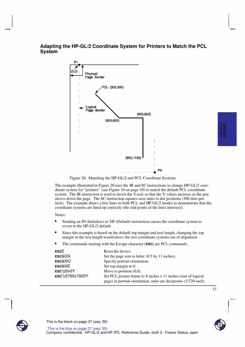
Adapting the HP-GL/2 Coordinate System for Printers to Match the PCLSystem
Figure 20. Matching the HP-GL/2 and PCL Coordinate Systems
The example illustrated in Figure 20 uses the IR and SC instructions to change HP-GL/2 coor-dinate system for “printers” (see Figure 10 on page 10) to match the default PCL coordinatesystem. The IR instruction is used to invert the Y-axis so that the Y values increase as the penmoves down the page. The SC instruction equates user-units to dot positions (300 dots-per-inch). The example draws a few lines in both PCL and HP-GL/2 modes to demonstrate that thecoordinate systems are lined up correctly (the end points of the lines intersect).
Notes:
Sending an IN (Initialize) or DF (Default) instruction causes the coordinate system torevert to the HP-GL/2 default.
Since this example is based on the default top margin and text length, changing the topmargin or the text length would move the two coordinate systems out of alignment.
The commands starting with the Escape character () are PCL commands.
E Reset the device.
&l2A Set the page size to letter (8.5 by 11 inches).
&l0O Specify portrait orientation.
&l0E Set top margin to 0.
*p0x0Y Move to position (0,0).
*c5760x7920Y Set PCL picture frame to 8 inches x 11 inches (size of logical
page) in portrait orientation; units are decipoints (1/720-inch).
This is the blue on page 37 (seq: 55)
K E R N E L
H P - G L / 2
8/12/2019 HPGL2-RTL ReferenceGuide 5961-3526 540pages Sep96
http://slidepdf.com/reader/full/hpgl2-rtl-referenceguide-5961-3526-540pages-sep96 56/539
38
This is the black on page 38 (seq: 56)
Company confidential. HP-GL/2 and HP RTL Reference Guide, draft 2. Freeze Status: open
*c0T Set picture frame anchor point to current PCL cursor position
(0,0).
%1B Enter HP-GL/2 mode with the HP-GL/2 cursor or pen at the PCL
cursor position.IN ; Initialize HP-GL/2 instruction values. (The IN instruction moves
the pen position from the anchor point to the HP-GL/2 origin, the
lower-left corner of the PCL picture frame.) Note that on color
devices, this instruction destroys the PCL color environment.
SP 1; Select pen number 1.
SC 0,3.3867,0,–3.3867,2; Set up a user scale with a user-unit equal to 1/300 inch. Scale
instruction type 2, the scale is the ratio of plotter-units/user-units
(1016 plotter-units-per-inch/300 dots-per-inch = 3.3867). The
negative Y-value changes the HP-GL/2 Y direction to match that
of the PCL coordinate system.
IR 0,100; Place P1—point (0,0)—at the top of the PCL picture frame.
PU 0,0; Lift the pen and move to (0,0), the upper left corner—since theHP-GL/2 coordinate system now matches the PCL coordinate sys-
tem. Every subsequent pen move can be specified using the same
coordinate numbers in either mode.
The following instructions demonstrate that the grids are synchro-
nized.
PU 300,300; Lift the pen and move it to (300,300).
PD 600,600; Draw a line to (600,600). This draws a line at a 45 angle down
from the starting point.
%1A Enter PCL mode with HP-GL/2’s pen position (600,600) being
inherited as PCL’s current active position (CAP).
*c300a4b0P Draw a horizontal line (rule) that is 300 PCL units wide by 4 PCL
units. Note that the cursor position after a rule is printed is at the
beginning of the rule—in this case (600,600).
%1B Enter HP-GL/2 mode (inheriting PCL’s CAP).
PU ; Lift the pen.
PR 300,0; Move to a point 300 user-units (dots) to the right.
PD ; Place the pen down.
PR 0,500; Print a line 500 user-units down.
%1A Enter PCL mode with the CAP at the current HP-GL/2 pen posi-
tion.
E Reset the device to end the job and eject a page.
Adapting the HP-GL/2 Coordinate System for Plotters to Match the HP RTLSystem
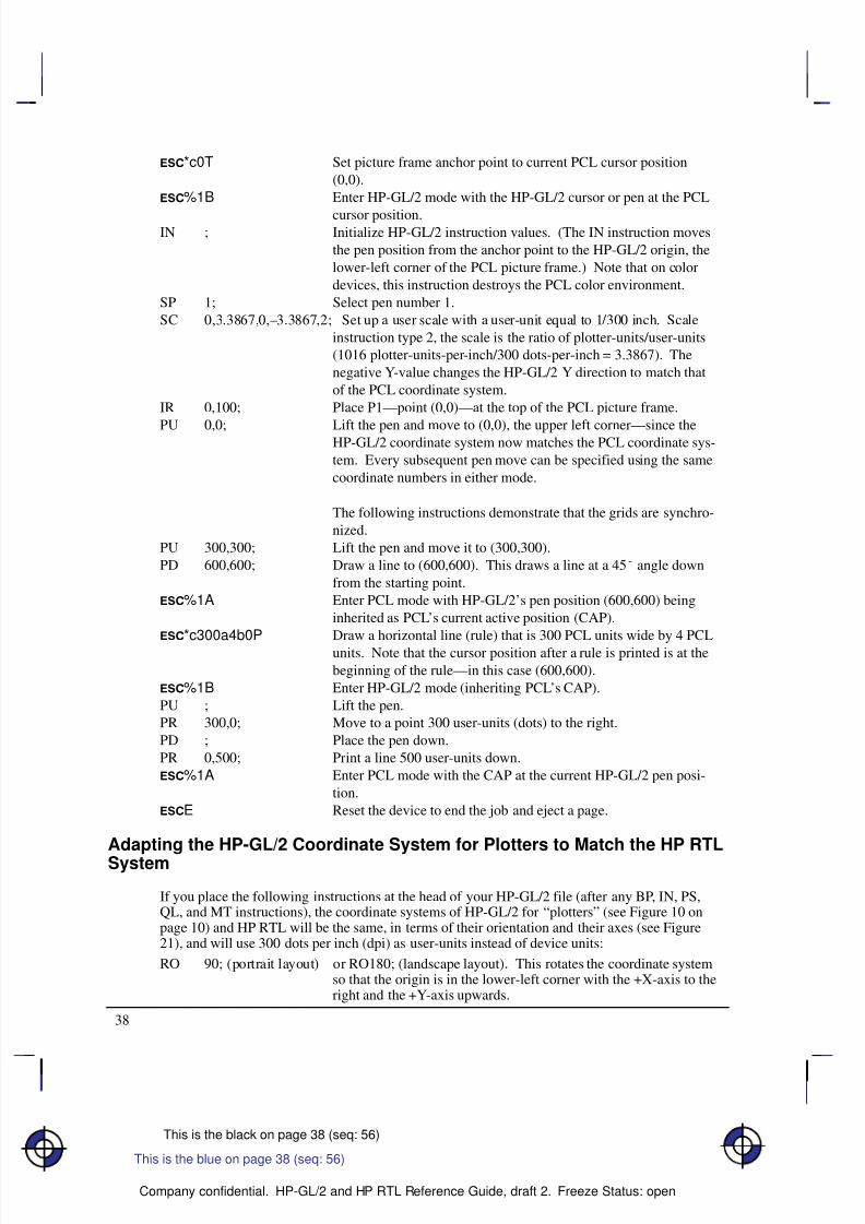
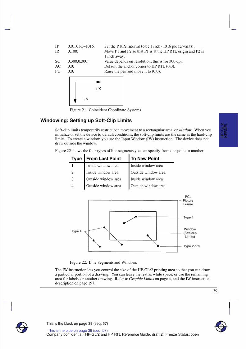
If you place the following instructions at the head of your HP-GL/2 file (after any BP, IN, PS,QL, and MT instructions), the coordinate systems of HP-GL/2 for “plotters” (see Figure 10 onpage 10) and HP RTL will be the same, in terms of their orientation and their axes (see Figure21), and will use 300 dots per inch (dpi) as user-units instead of device units:
RO 90; (portrait layout) or RO180; (landscape layout). This rotates the coordinate systemso that the origin is in the lower-left corner with the +X-axis to theright and the +Y-axis upwards.
This is the blue on page 38 (seq: 56)
8/12/2019 HPGL2-RTL ReferenceGuide 5961-3526 540pages Sep96
http://slidepdf.com/reader/full/hpgl2-rtl-referenceguide-5961-3526-540pages-sep96 57/539
8/12/2019 HPGL2-RTL ReferenceGuide 5961-3526 540pages Sep96
http://slidepdf.com/reader/full/hpgl2-rtl-referenceguide-5961-3526-540pages-sep96 58/539
40
This is the black on page 40 (seq: 58)
Company confidential. HP-GL/2 and HP RTL Reference Guide, draft 2. Freeze Status: open
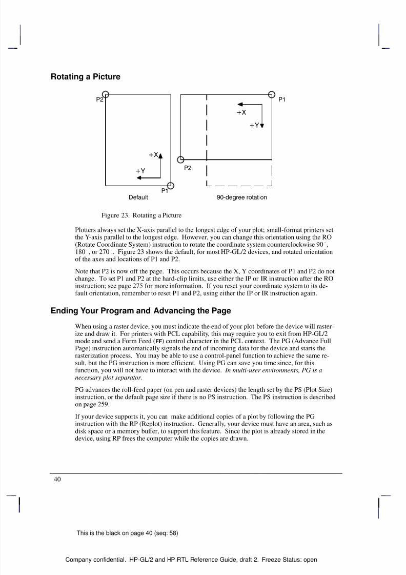
Rotating a Picture
Figure 23. Rotating a Picture
Plotters always set the X-axis parallel to the longest edge of your plot; small-format printers setthe Y-axis parallel to the longest edge. However, you can change this orientation using the RO(Rotate Coordinate System) instruction to rotate the coordinate system counterclockwise 90,180, or 270. Figure 23 shows the default, for most HP-GL/2 devices, and rotated orientationof the axes and locations of P1 and P2.
Note that P2 is now off the page. This occurs because the X, Y coordinates of P1 and P2 do notchange. To set P1 and P2 at the hard-clip limits, use either the IP or IR instruction after the ROinstruction; see page 275 for more information. If you reset your coordinate system to its de-fault orientation, remember to reset P1 and P2, using either the IP or IR instruction again.
Ending Your Program and Advancing the Page
When using a raster device, you must indicate the end of your plot before the device will raster-ize and draw it. For printers with PCL capability, this may require you to exit from HP-GL/2mode and send a Form Feed () control character in the PCL context. The PG (Advance FullPage) instruction automatically signals the end of incoming data for the device and starts therasterization process. You may be able to use a control-panel function to achieve the same re-sult, but the PG instruction is more efficient. Using PG can save you time since, for thisfunction, you will not have to interact with the device. In multi-user environments, PG is anecessary plot separator.
PG advances the roll-feed paper (on pen and raster devices) the length set by the PS (Plot Size)instruction, or the default page size if there is no PS instruction. The PS instruction is described
on page 259.
If your device supports it, you can make additional copies of a plot by following the PGinstruction with the RP (Replot) instruction. Generally, your device must have an area, such asdisk space or a memory buffer, to support this feature. Since the plot is already stored in thedevice, using RP frees the computer while the copies are drawn.
8/12/2019 HPGL2-RTL ReferenceGuide 5961-3526 540pages Sep96
http://slidepdf.com/reader/full/hpgl2-rtl-referenceguide-5961-3526-540pages-sep96 59/539
41
This is the black on page 41 (seq: 59)
Company confidential. HP-GL/2 and HP RTL Reference Guide, draft 2. Freeze Status: open
The Vector Group
The Vector Group instructions enable you to achieve the following results in your programs:Use absolute and relative coordinates when plotting.
Draw lines, arcs, and circles.
Encode coordinates to increase your device’s throughput.
The following instructions form the Vector Group:
Á Á Á Á Á Á Á Á Á Á
Á Á Á Á Á Á Á Á Á Á
AA Arc AbsoluteÁ Á Á Á Á Á Á Á Á Á Á Á Á Á Á Á Á Á
Á Á Á Á Á Á Á Á Á Á Á Á Á Á Á Á Á Á
Draws an arc using absolute coordinates.Á Á Á Á Á Á Á Á Á Á
Á Á Á Á Á Á Á Á Á Á
AR Arc RelativeÁ Á Á Á Á Á Á Á Á Á Á Á Á Á Á Á Á Á
Á Á Á Á Á Á Á Á Á Á Á Á Á Á Á Á Á Á
Draws an arc using relative coordinates.Á Á Á Á Á Á Á Á Á Á
Á
Á Á Á Á Á Á Á Á Á
Á Á Á Á Á Á Á Á Á Á
AT Absolute Arc Three PointÁ Á Á Á Á Á Á Á Á Á Á Á Á Á Á Á Á Á
Á
Á Á Á Á Á Á Á Á Á Á Á Á Á Á Á Á Á
Á Á Á Á Á Á Á Á Á Á Á Á Á Á Á Á Á Á
Draws an arc from the current pen location through two ab-solute points.
Á Á Á Á Á Á Á Á Á Á
Á Á Á Á Á Á Á Á Á Á
CI CircleÁ Á Á Á Á Á Á Á Á Á Á Á Á Á Á Á Á Á
Á Á Á Á Á Á Á Á Á Á Á Á Á Á Á Á Á Á
Draws a circle with a specified radius.
Á Á Á Á Á Á Á Á Á Á
Á Á Á Á Á Á Á Á Á Á
PA Plot AbsoluteÁ Á Á Á Á Á Á Á Á Á Á Á Á Á Á Á Á Á
Á Á Á Á Á Á Á Á Á Á Á Á Á Á Á Á Á Á
Enables movement to absolute coordinate locations, withrespect to the origin (0,0).
Á Á Á Á Á Á Á Á Á Á
Á Á Á Á Á Á Á Á Á Á
PD Pen DownÁ Á Á Á Á Á Á Á Á Á Á Á Á Á Á Á Á Á
Á Á Á Á Á Á Á Á Á Á Á Á Á Á Á Á Á Á
Lowers the “pen” to the page.Á Á Á Á Á Á Á Á Á Á
Á
Á Á Á Á Á Á Á Á Á
Á Á Á Á Á Á Á Á Á Á
PE Polyline EncodedÁ Á Á Á Á Á Á Á Á Á Á Á Á Á Á Á Á Á
Á
Á Á Á Á Á Á Á Á Á Á Á Á Á Á Á Á Á
Á Á Á Á Á Á Á Á Á Á Á Á Á Á Á Á Á Á
Increases throughput by encrypting common HP-GL/2instructions.
Á Á Á Á Á Á Á Á Á Á
Á Á Á Á Á Á Á Á Á Á
PR Plot RelativeÁ Á Á Á Á Á Á Á Á Á Á Á Á Á Á Á Á Á
Á Á Á Á Á Á Á Á Á Á Á Á Á Á Á Á Á Á
Enables movement relative to the current pen location.
Á Á Á Á Á Á Á Á Á Á
Á Á Á Á Á Á Á Á Á Á
PU Pen UpÁ Á Á Á Á Á Á Á Á Á Á Á Á Á Á Á Á Á
Á Á Á Á Á Á Á Á Á Á Á Á Á Á Á Á Á Á
Lifts the pen from the page.
Á Á Á Á Á Á Á Á Á Á
Á Á Á Á Á Á Á Á Á Á
RT Relative Arc Three PointÁ Á Á Á Á Á Á Á Á Á Á Á Á Á Á Á Á Á
Á Á Á Á Á Á Á Á Á Á Á Á Á Á Á Á Á Á
Draws an arc from the current pen location through two rela-tive points.
The factory environment defaults are:
The plotting mode is absolute (the PA instruction).
The pen state is up (PU).
Pen Up or Down
Most HP-GL/2 instructions perform their functions with the pen either up or down. Specifyingthe pen’s up/down state is necessary to avoid drawing unwanted lines between figures. The PU(Pen Up) instruction raises the pen and can also move to a desired plotting location beforedrawing. The PD (Pen Down) instruction lowers the pen and can draw from the current loca-tion to a specified location. Turning on the device or sending an IN (Initialize) instructionraises the pen. Some instructions automatically cause the pen to be down (see page 23).
Drawing LinesYou can draw lines between two points (X,Y coordinate pairs) using the PD (Pen Down)instruction and a series of absolute or relative coordinate pairs. The device draws only the por-tion of the line that falls within the effective window.
Note: When using HP-GL/2 to draw lines, you can increase your device’s throughput by usingthe Polyline Encoded (PE) instruction to send coordinates. The PE instruction requires that youconvert coordinates from decimal to base 64 or 32. This conversion increases especially the
This is the blue on page 41 (seq: 59)
K E R N E L
H P - G L / 2

8/12/2019 HPGL2-RTL ReferenceGuide 5961-3526 540pages Sep96
http://slidepdf.com/reader/full/hpgl2-rtl-referenceguide-5961-3526-540pages-sep96 60/539
42
This is the black on page 42 (seq: 60)
Company confidential. HP-GL/2 and HP RTL Reference Guide, draft 2. Freeze Status: open
throughput when you use a serial interface. The PE instruction, with its parameters, is used inplace of the PA, PD, PR, PU, and SP instructions.
In the following example, note that the PA (Plot Absolute) instruction specifies absolute plot-ting, and the coordinate pair (0,0) sets the beginning pen location.
PA 0,0; Begin absolute plotting from coordinate (0,0).
PD 2500,0,0,1500,0,0; Specify Pen Down and draw lines between the points.
Figure 24. Drawing Lines
Note: Any line drawn along the border of the effective window causes the line to be clipped,producing a line width of one-half of what it should be. For example, in the above plot, thelines from (0,0) to (0,1500), and (0,0) to (2500,0) are clipped if the origin (0,0) is one corner of the effective window.
Drawing Circles
The CI (Circle) instruction uses your current pen position as the center of the circle; you speci-fy the radius of the circle.
Figure 25. Drawing Circles and Arcs

8/12/2019 HPGL2-RTL ReferenceGuide 5961-3526 540pages Sep96
http://slidepdf.com/reader/full/hpgl2-rtl-referenceguide-5961-3526-540pages-sep96 61/539
43
This is the black on page 43 (seq: 61)
Company confidential. HP-GL/2 and HP RTL Reference Guide, draft 2. Freeze Status: open
The following example shows a simple instruction sequence using CI to draw a circle with aradius of 500 plotter-units. The circle is shown on the left of Figure 25.
PA 2400,2500; Specify absolute plotting and move to position (2400,2500).
CI 500; Draw a circle with a radius of 500 plotter-units; the center of thecircle is the current pen location (2400,2500). The CI instruction
automatically causes the pen to be lowered.
Drawing Arcs
The AA (Arc Absolute) and AR (Arc Relative) instructions use the following method for draw-ing arcs. Your current pen location becomes one end of the arc; you specify the center pointwith one parameter (setting the radius), and set another parameter to specify the number of de-grees through which you want the arc drawn.
You can also draw arcs using the AT (Absolute Arc Three Point) and RT (Relative Arc ThreePoint) instructions. These instructions use three known points (your current pen location plus
two points you specify) to calculate a circle and draw the appropriate arc segment of its circum-ference. The arc is drawn from the starting point so that it passes through the intermediatepoint before the end point, using clockwise or counter-clockwise drawing as required. Refer toFigure 26.
Figure 26. Arcs through Three Given Points
The following example shows a simple instruction sequence using AA to draw an arc. The arcis shown on the right of Figure 25.
PA 4200,2900; Set starting point to (4200,2900).
PD ; Set pen down.
AA 4600,2500,–180; Using the Arc Absolute instruction, specify the pivot point of the
arc, thereby setting the radius; draw the arc for 180 in a negative
angle of rotation.
This is the blue on page 43 (seq: 61)
K E R N E L
H P - G L / 2
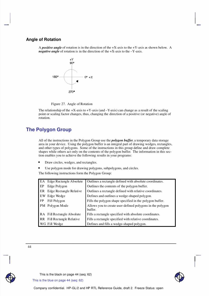
8/12/2019 HPGL2-RTL ReferenceGuide 5961-3526 540pages Sep96
http://slidepdf.com/reader/full/hpgl2-rtl-referenceguide-5961-3526-540pages-sep96 62/539
44
This is the black on page 44 (seq: 62)
Company confidential. HP-GL/2 and HP RTL Reference Guide, draft 2. Freeze Status: open
Angle of Rotation
A positive angle of rotation is in the direction of the +X-axis to the +Y-axis as shown below. A
negative angle of rotation is in the direction of the +X-axis to the –Y-axis.
Figure 27. Angle of Rotation
The relationship of the +X-axis to +Y-axis (and –Y-axis) can change as a result of the scalingpoint or scaling factor changes, thus, changing the direction of a positive (or negative) angle of rotation.
The Polygon Group
All of the instructions in the Polygon Group use the polygon buffer, a temporary data storagearea in your device. Using the polygon buffer is an integral part of drawing wedges, rectangles,and other types of polygons. Some of the instructions in this group define and draw completeshapes while others act only on the contents of the polygon buffer. The information in this sec-
tion enables you to achieve the following results in your programs:
Draw circles, wedges, and rectangles.
Use polygon mode for drawing polygons, subpolygons, and circles.
The following instructions form the Polygon Group:
Á Á Á Á Á Á Á Á Á
Á Á Á Á Á Á Á Á Á
EA Edge Rectangle AbsoluteÁ Á Á Á Á Á Á Á Á Á Á Á Á Á Á Á Á Á
Á Á Á Á Á Á Á Á Á Á Á Á Á Á Á Á Á Á
Outlines a rectangle defined with absolute coordinates.
Á Á Á Á Á Á Á Á Á
Á Á Á Á Á Á Á Á Á
EP Edge PolygonÁ Á Á Á Á Á Á Á Á Á Á Á Á Á Á Á Á Á
Á Á Á Á Á Á Á Á Á Á Á Á Á Á Á Á Á Á
Outlines the contents of the polygon buffer.
Á Á Á Á Á Á Á Á Á
Á Á Á Á Á Á Á Á Á
ER Edge Rectangle RelativeÁ Á Á Á Á Á Á Á Á Á Á Á Á Á Á Á Á Á
Á Á Á Á Á Á Á Á Á Á Á Á Á Á Á Á Á Á
Outlines a rectangle defined with relative coordinates.
Á Á Á Á Á Á Á Á Á
Á Á Á Á Á Á Á Á Á
EW Edge WedgeÁ Á Á Á Á Á Á Á Á Á Á Á Á Á Á Á Á Á
Á Á Á Á Á Á Á Á Á Á Á Á Á Á Á Á Á Á
Defines and outlines a wedge-shaped polygon.Á Á Á Á Á Á Á Á Á
Á Á Á Á Á Á Á Á Á
FP Fill PolygonÁ Á Á Á Á Á Á Á Á Á Á Á Á Á Á Á Á Á
Á Á Á Á Á Á Á Á Á Á Á Á Á Á Á Á Á Á
Fills the polygon shape specified in the polygon buffer.Á Á Á Á Á Á Á Á Á
Á Á Á Á Á Á Á Á Á
Á Á Á Á Á Á Á Á Á
PM Polygon ModeÁ Á Á Á Á Á Á Á Á Á Á Á Á Á Á Á Á Á
Á
Á Á Á Á Á Á Á Á Á Á Á Á Á Á Á Á Á
Á Á Á Á Á Á Á Á Á Á Á Á Á Á Á Á Á Á
Allows you to create user-defined polygons in the polygonbuffer.
Á Á Á Á Á Á Á Á Á
Á Á Á Á Á Á Á Á Á
RA Fill Rectangle Absolute Á Á Á Á Á Á Á Á Á Á Á Á Á Á Á Á Á Á
Á Á Á Á Á Á Á Á Á Á Á Á Á Á Á Á Á Á
Fills a rectangle specified with absolute coordinates.
Á Á Á Á Á Á Á Á Á
Á Á Á Á Á Á Á Á Á
RR Fill Rectangle Relative Á Á Á Á Á Á Á Á Á Á Á Á Á Á Á Á Á Á
Á Á Á Á Á Á Á Á Á Á Á Á Á Á Á Á Á Á
Fills a rectangle specified with relative coordinates.
Á Á Á Á Á Á Á Á Á
Á Á Á Á Á Á Á Á Á
WG Fill WedgeÁ Á Á Á Á Á Á Á Á Á Á Á Á Á Á Á Á Á
Á Á Á Á Á Á Á Á Á Á Á Á Á Á Á Á Á Á
Defines and fills a wedge-shaped polygon.
This is the blue on page 44 (seq: 62)
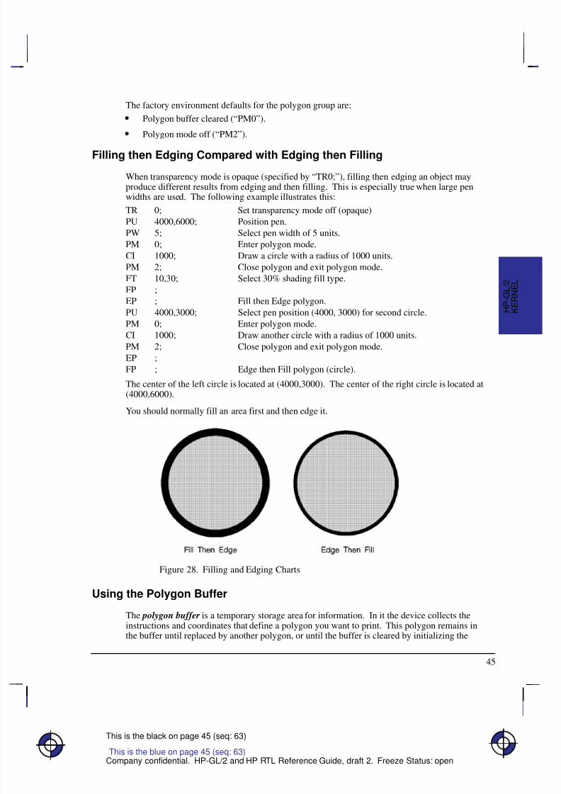
8/12/2019 HPGL2-RTL ReferenceGuide 5961-3526 540pages Sep96
http://slidepdf.com/reader/full/hpgl2-rtl-referenceguide-5961-3526-540pages-sep96 63/539
45
This is the black on page 45 (seq: 63)
Company confidential. HP-GL/2 and HP RTL Reference Guide, draft 2. Freeze Status: open
The factory environment defaults for the polygon group are:
Polygon buffer cleared (“PM0”).
Polygon mode off (“PM2”).
Filling then Edging Compared with Edging then Filling
When transparency mode is opaque (specified by “TR0;”), filling then edging an object mayproduce different results from edging and then filling. This is especially true when large penwidths are used. The following example illustrates this:
TR 0; Set transparency mode off (opaque)
PU 4000,6000; Position pen.
PW 5; Select pen width of 5 units.
PM 0; Enter polygon mode.
CI 1000; Draw a circle with a radius of 1000 units.
PM 2; Close polygon and exit polygon mode.
FT 10,30; Select 30% shading fill type.FP ;
EP ; Fill then Edge polygon.
PU 4000,3000; Select pen position (4000, 3000) for second circle.
PM 0; Enter polygon mode.
CI 1000; Draw another circle with a radius of 1000 units.
PM 2; Close polygon and exit polygon mode.
EP ;
FP ; Edge then Fill polygon (circle).
The center of the left circle is located at (4000,3000). The center of the right circle is located at(4000,6000).
You should normally fill an area first and then edge it.
Figure 28. Filling and Edging Charts
Using the Polygon Buffer
The polygon buffer is a temporary storage area for information. In it the device collects theinstructions and coordinates that define a polygon you want to print. This polygon remains inthe buffer until replaced by another polygon, or until the buffer is cleared by initializing the
K E R N E L
H P - G L / 2
This is the blue on page 45 (seq: 63)
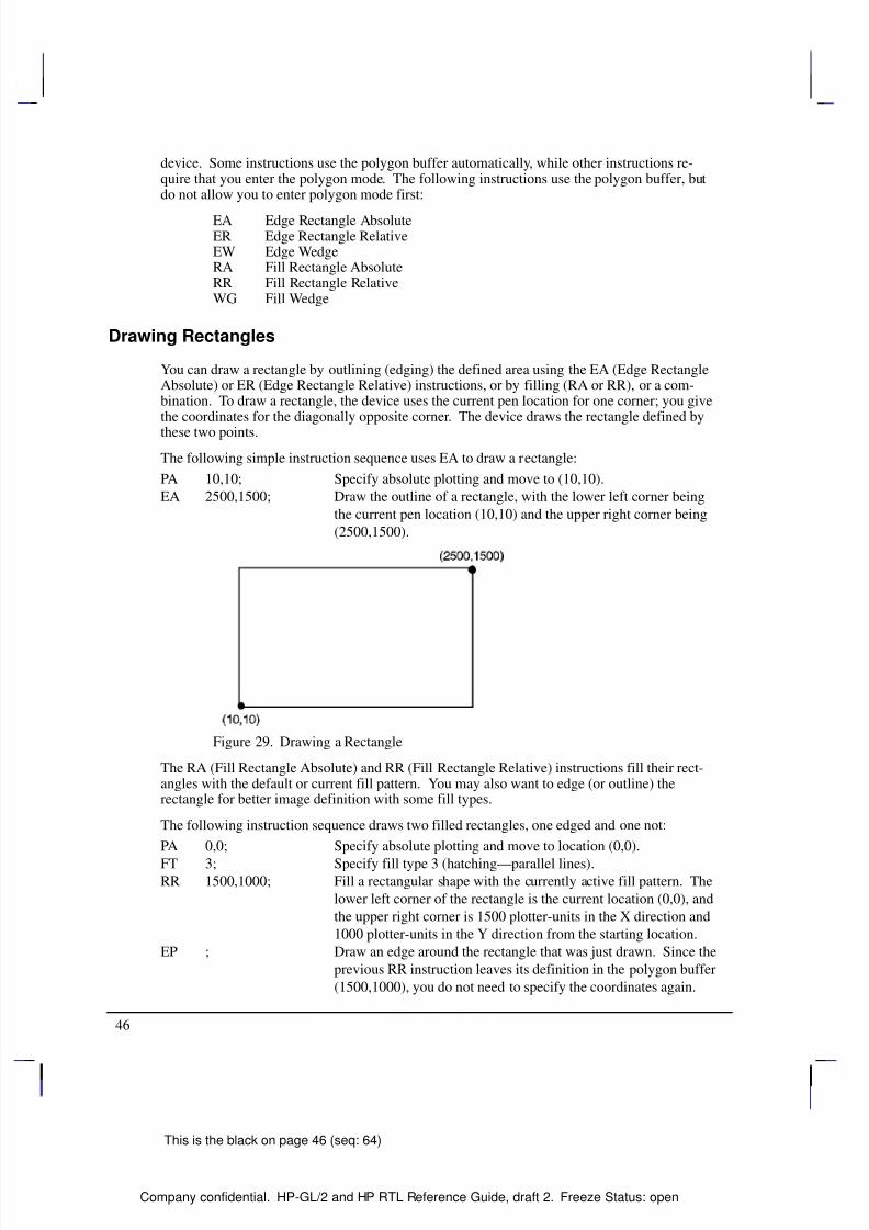
8/12/2019 HPGL2-RTL ReferenceGuide 5961-3526 540pages Sep96
http://slidepdf.com/reader/full/hpgl2-rtl-referenceguide-5961-3526-540pages-sep96 64/539
46
This is the black on page 46 (seq: 64)
Company confidential. HP-GL/2 and HP RTL Reference Guide, draft 2. Freeze Status: open
device. Some instructions use the polygon buffer automatically, while other instructions re-quire that you enter the polygon mode. The following instructions use the polygon buffer, butdo not allow you to enter polygon mode first:
EA Edge Rectangle AbsoluteER Edge Rectangle RelativeEW Edge WedgeRA Fill Rectangle AbsoluteRR Fill Rectangle RelativeWG Fill Wedge
Drawing Rectangles
You can draw a rectangle by outlining (edging) the defined area using the EA (Edge RectangleAbsolute) or ER (Edge Rectangle Relative) instructions, or by filling (RA or RR), or a com-bination. To draw a rectangle, the device uses the current pen location for one corner; you givethe coordinates for the diagonally opposite corner. The device draws the rectangle defined by
these two points.
The following simple instruction sequence uses EA to draw a rectangle:
PA 10,10; Specify absolute plotting and move to (10,10).
EA 2500,1500; Draw the outline of a rectangle, with the lower left corner being
the current pen location (10,10) and the upper right corner being
(2500,1500).
Figure 29. Drawing a Rectangle
The RA (Fill Rectangle Absolute) and RR (Fill Rectangle Relative) instructions fill their rect-angles with the default or current fill pattern. You may also want to edge (or outline) therectangle for better image definition with some fill types.
The following instruction sequence draws two filled rectangles, one edged and one not:
PA 0,0; Specify absolute plotting and move to location (0,0).
FT 3; Specify fill type 3 (hatching—parallel lines).RR 1500,1000; Fill a rectangular shape with the currently active fill pattern. The
lower left corner of the rectangle is the current location (0,0), and
the upper right corner is 1500 plotter-units in the X direction and
1000 plotter-units in the Y direction from the starting location.
EP ; Draw an edge around the rectangle that was just drawn. Since the
previous RR instruction leaves its definition in the polygon buffer
(1500,1000), you do not need to specify the coordinates again.
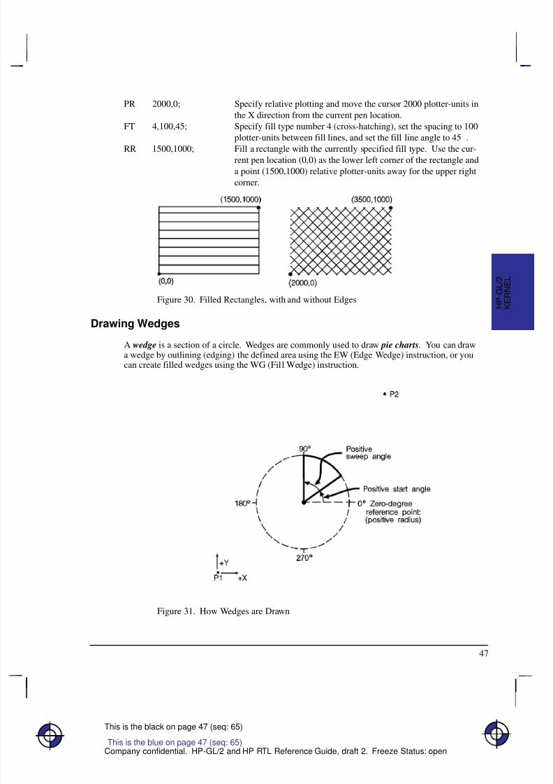
8/12/2019 HPGL2-RTL ReferenceGuide 5961-3526 540pages Sep96
http://slidepdf.com/reader/full/hpgl2-rtl-referenceguide-5961-3526-540pages-sep96 65/539
47
This is the black on page 47 (seq: 65)
Company confidential. HP-GL/2 and HP RTL Reference Guide, draft 2. Freeze Status: open
PR 2000,0; Specify relative plotting and move the cursor 2000 plotter-units in
the X direction from the current pen location.
FT 4,100,45; Specify fill type number 4 (cross-hatching), set the spacing to 100
plotter-units between fill lines, and set the fill line angle to 45.RR 1500,1000; Fill a rectangle with the currently specified fill type. Use the cur-
rent pen location (0,0) as the lower left corner of the rectangle and
a point (1500,1000) relative plotter-units away for the upper right
corner.
Figure 30. Filled Rectangles, with and without Edges
Drawing Wedges
A wedge is a section of a circle. Wedges are commonly used to draw pie charts. You can drawa wedge by outlining (edging) the defined area using the EW (Edge Wedge) instruction, or youcan create filled wedges using the WG (Fill Wedge) instruction.
Figure 31. How Wedges are Drawn
This is the blue on page 47 (seq: 65)
K E R N E L
H P - G L / 2
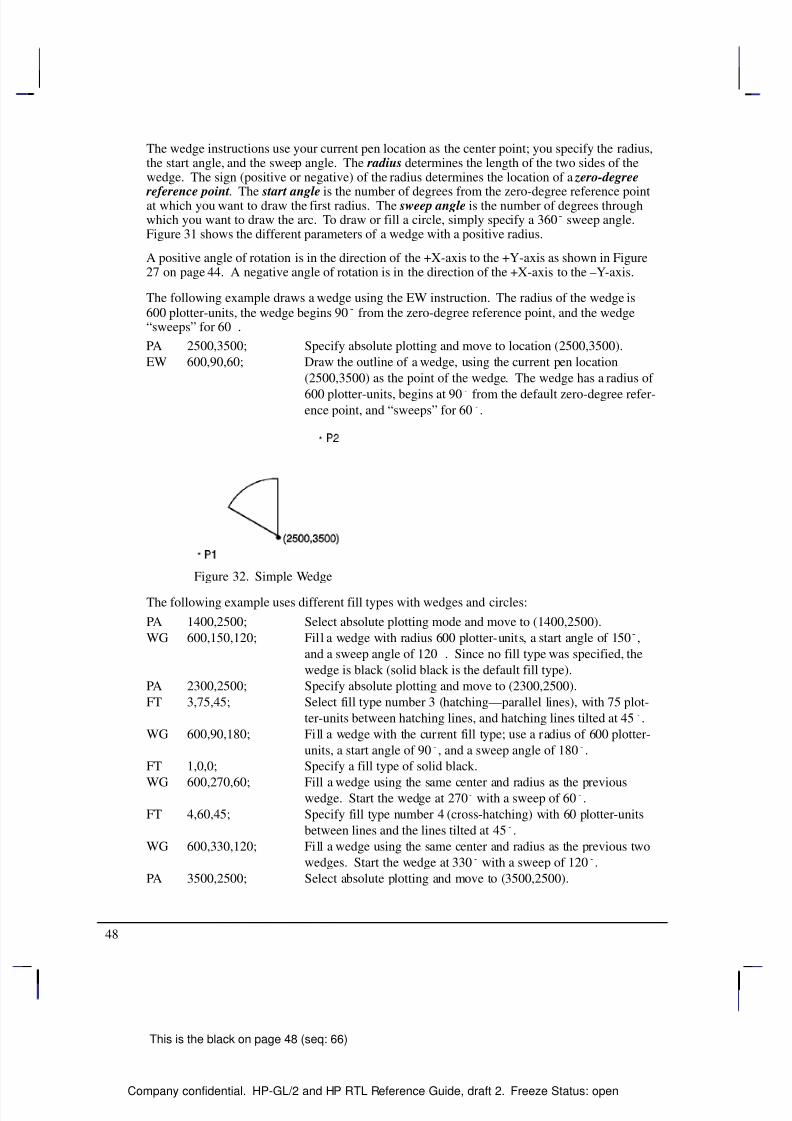
8/12/2019 HPGL2-RTL ReferenceGuide 5961-3526 540pages Sep96
http://slidepdf.com/reader/full/hpgl2-rtl-referenceguide-5961-3526-540pages-sep96 66/539
48
This is the black on page 48 (seq: 66)
Company confidential. HP-GL/2 and HP RTL Reference Guide, draft 2. Freeze Status: open
The wedge instructions use your current pen location as the center point; you specify the radius,the start angle, and the sweep angle. The radius determines the length of the two sides of thewedge. The sign (positive or negative) of the radius determines the location of a zero-degree
reference point. The start angle is the number of degrees from the zero-degree reference pointat which you want to draw the first radius. The sweep angle is the number of degrees throughwhich you want to draw the arc. To draw or fill a circle, simply specify a 360 sweep angle.Figure 31 shows the different parameters of a wedge with a positive radius.
A positive angle of rotation is in the direction of the +X-axis to the +Y-axis as shown in Figure27 on page 44. A negative angle of rotation is in the direction of the +X-axis to the –Y-axis.
The following example draws a wedge using the EW instruction. The radius of the wedge is600 plotter-units, the wedge begins 90 from the zero-degree reference point, and the wedge“sweeps” for 60.
PA 2500,3500; Specify absolute plotting and move to location (2500,3500).
EW 600,90,60; Draw the outline of a wedge, using the current pen location
(2500,3500) as the point of the wedge. The wedge has a radius of
600 plotter-units, begins at 90 from the default zero-degree refer-ence point, and “sweeps” for 60.
Figure 32. Simple Wedge
The following example uses different fill types with wedges and circles:
PA 1400,2500; Select absolute plotting mode and move to (1400,2500).
WG 600,150,120; Fill a wedge with radius 600 plotter-units, a start angle of 150,
and a sweep angle of 120. Since no fill type was specified, the
wedge is black (solid black is the default fill type).
PA 2300,2500; Specify absolute plotting and move to (2300,2500).
FT 3,75,45; Select fill type number 3 (hatching—parallel lines), with 75 plot-
ter-units between hatching lines, and hatching lines tilted at 45.
WG 600,90,180; Fill a wedge with the current fill type; use a radius of 600 plotter-
units, a start angle of 90, and a sweep angle of 180.
FT 1,0,0; Specify a fill type of solid black.
WG 600,270,60; Fill a wedge using the same center and radius as the previouswedge. Start the wedge at 270 with a sweep of 60.
FT 4,60,45; Specify fill type number 4 (cross-hatching) with 60 plotter-units
between lines and the lines tilted at 45.
WG 600,330,120; Fill a wedge using the same center and radius as the previous two
wedges. Start the wedge at 330 with a sweep of 120.
PA 3500,2500; Select absolute plotting and move to (3500,2500).
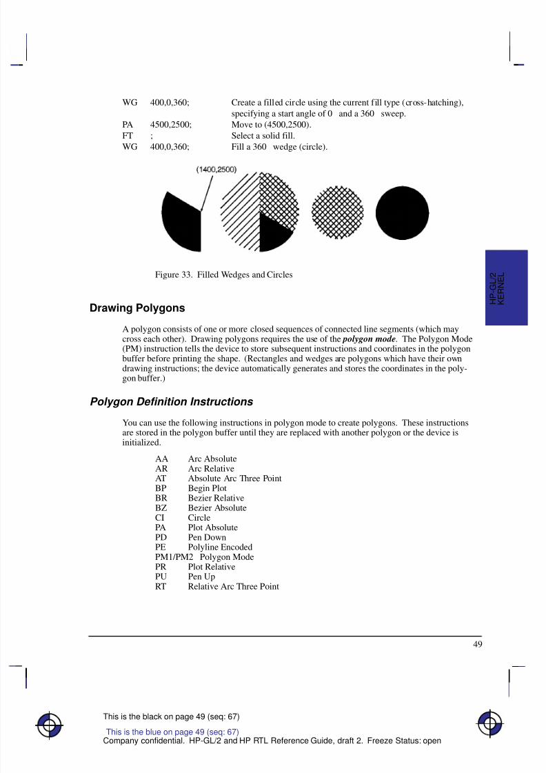
8/12/2019 HPGL2-RTL ReferenceGuide 5961-3526 540pages Sep96
http://slidepdf.com/reader/full/hpgl2-rtl-referenceguide-5961-3526-540pages-sep96 67/539
49
This is the black on page 49 (seq: 67)
Company confidential. HP-GL/2 and HP RTL Reference Guide, draft 2. Freeze Status: open
WG 400,0,360; Create a filled circle using the current fill type (cross-hatching),
specifying a start angle of 0 and a 360 sweep.
PA 4500,2500; Move to (4500,2500).
FT ; Select a solid fill.WG 400,0,360; Fill a 360 wedge (circle).
Figure 33. Filled Wedges and Circles
Drawing Polygons
A polygon consists of one or more closed sequences of connected line segments (which maycross each other). Drawing polygons requires the use of the polygon mode. The Polygon Mode(PM) instruction tells the device to store subsequent instructions and coordinates in the polygonbuffer before printing the shape. (Rectangles and wedges are polygons which have their owndrawing instructions; the device automatically generates and stores the coordinates in the poly-gon buffer.)
Polygon Definition Instructions You can use the following instructions in polygon mode to create polygons. These instructionsare stored in the polygon buffer until they are replaced with another polygon or the device isinitialized.
AA Arc AbsoluteAR Arc RelativeAT Absolute Arc Three PointBP Begin PlotBR Bezier RelativeBZ Bezier AbsoluteCI CirclePA Plot Absolute
PD Pen DownPE Polyline EncodedPM1/PM2 Polygon ModePR Plot RelativePU Pen UpRT Relative Arc Three Point
This is the blue on page 49 (seq: 67)
K E R N E L
H P - G L / 2
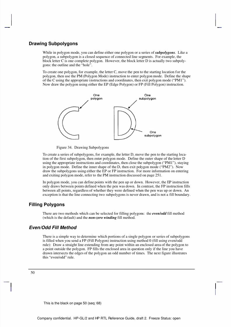
8/12/2019 HPGL2-RTL ReferenceGuide 5961-3526 540pages Sep96
http://slidepdf.com/reader/full/hpgl2-rtl-referenceguide-5961-3526-540pages-sep96 68/539
50
This is the black on page 50 (seq: 68)
Company confidential. HP-GL/2 and HP RTL Reference Guide, draft 2. Freeze Status: open
Drawing Subpolygons
While in polygon mode, you can define either one polygon or a series of subpolygons. Like a
polygon, a subpolygon is a closed sequence of connected line segments. For example, theblock letter C is one complete polygon. However, the block letter D is actually two subpoly-gons: the outline and the “hole”.
To create one polygon, for example, the letter C, move the pen to the starting location for thepolygon, then use the PM (Polygon Mode) instruction to enter polygon mode. Define the shapeof the C using the appropriate instructions and coordinates, then exit polygon mode (“PM1”).Now draw the polygon using either the EP (Edge Polygon) or FP (Fill Polygon) instruction.
Figure 34. Drawing Subpolygons
To create a series of subpolygons, for example, the letter D, move the pen to the starting loca-tion of the first subpolygon, then enter polygon mode. Define the outer shape of the letter Dusing the appropriate instructions and coordinates, then close the subpolygon (“PM1”), stayingin polygon mode. Define the inner shape of the D, then exit polygon mode (“PM2”). Now
draw the subpolygons using either the EP or FP instruction. For more information on enteringand exiting polygon mode, refer to the PM instruction discussed on page 251.
In polygon mode, you can define points with the pen up or down. However, the EP instructiononly draws between points defined when the pen was down. In contrast, the FP instruction fillsbetween all points, regardless of whether they were defined when the pen was up or down. Anexception is that the line connecting two subpolygons is never drawn, and is not a fill boundary.
Filling Polygons
There are two methods which can be selected for filling polygons: the even/odd fill method(which is the default) and the non-zero winding fill method.
Even/Odd Fill Method There is a simple way to determine which portions of a single polygon or series of subpolygonsis filled when you send a FP (Fill Polygon) instruction using method 0 (fill using even/oddrule): Draw a straight line extending from any point within an enclosed area of the polygon toa point outside the polygon. FP fills the enclosed area in question only if the line you havedrawn intersects the edges of the polygon an odd number of times. The next figure illustratesthis “even/odd” rule.
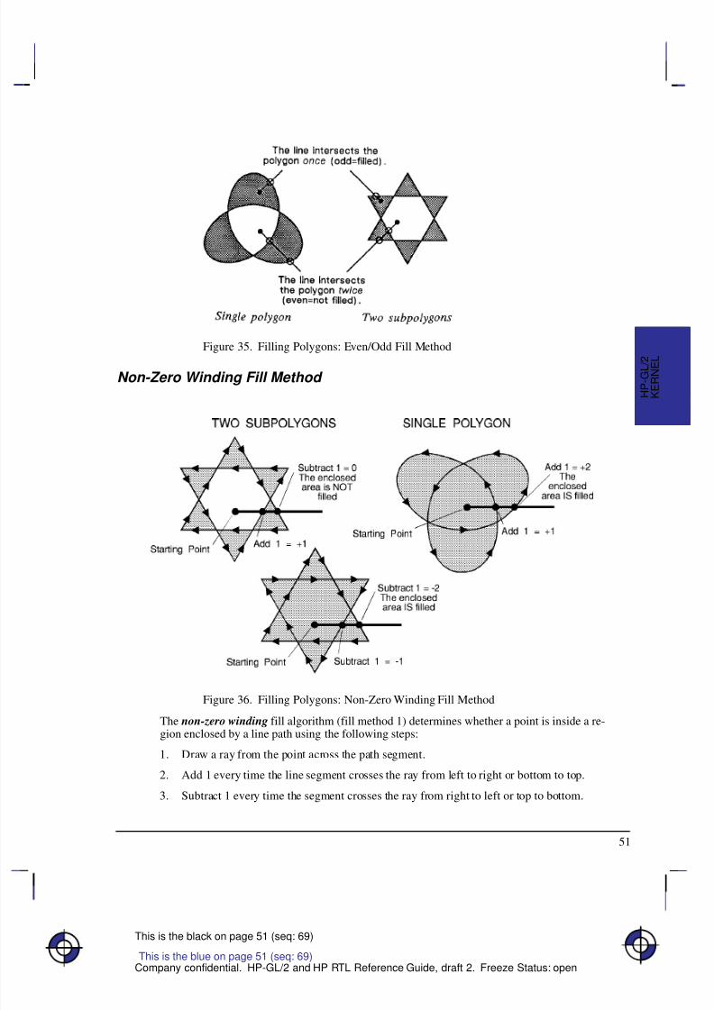
8/12/2019 HPGL2-RTL ReferenceGuide 5961-3526 540pages Sep96
http://slidepdf.com/reader/full/hpgl2-rtl-referenceguide-5961-3526-540pages-sep96 69/539
51
This is the black on page 51 (seq: 69)
Company confidential. HP-GL/2 and HP RTL Reference Guide, draft 2. Freeze Status: open
Figure 35. Filling Polygons: Even/Odd Fill Method
Non-Zero Winding Fill Method
Figure 36. Filling Polygons: Non-Zero Winding Fill Method
The non-zero winding fill algorithm (fill method 1) determines whether a point is inside a re-gion enclosed by a line path using the following steps:
1. Draw a ray from the point across the path segment.
2. Add 1 every time the line segment crosses the ray from left to right or bottom to top.
3. Subtract 1 every time the segment crosses the ray from right to left or top to bottom.
This is the blue on page 51 (seq: 69)
K E R N E L
H P - G L / 2
8/12/2019 HPGL2-RTL ReferenceGuide 5961-3526 540pages Sep96
http://slidepdf.com/reader/full/hpgl2-rtl-referenceguide-5961-3526-540pages-sep96 70/539
52
This is the black on page 52 (seq: 70)
Company confidential. HP-GL/2 and HP RTL Reference Guide, draft 2. Freeze Status: open
4. FP fills the enclosed area in question if the sum of steps 2 and 3 is non-zero.
Figure 36 illustrates the non-zero winding fill concept. Note the importance of the direction inwhich the lines are drawn.
Drawing Circles in Polygon Mode
Polygon mode interprets the CI (Circle) instruction differently from the other HP-GL/2 instruc-tions. The device treats a circle as a complete subpolygon. The device automatically closesthe first polygon (if any) before starting the circle, and uses the first coordinates (if any) afterthe circle is drawn to start a new subpolygon.
If you did not close your first polygon completely before sending the CI instruction, the deviceautomatically closes the polygon by adding a point (at the starting point of the previous sub-polygon). This can change your current pen location and the placement of the circle in yourpolygon, resulting in an inaccurate polygon.
A circle (360 arc) specified by AA, AR, AT, or RT is not treated as if it was preceded and fol-lowed by “PM1”.
CI with a zero radius is a syntactically correct but geometrically degenerate subpolygon thatproduces a dot. The following example shows how CI can produce syntactically incompletesubpolygons:
PU ; Pen Up.
PA 1000,1000; Move to (1000,1000).
PM 0; Enter polygon mode with the point (1000,1000) in the buffer.
CI 200: The subpolygon consisting of the single point (1000,1000) is im-
plicitly closed; it has fewer than three points, and effectively
disappears. After this CI instruction, the pen-up state and the
location (1000,1000) are restored, but this point is not put into the
polygon buffer.
CI 500; This CI instruction again forces closure, and the restored position
point is discarded.
PM 2; Close polygon mode.
FP ; Fill polygon. The result is a torus without a center dot.
Calculating How Much of the Polygon Buffer is Used
You can use the following formula to estimate how much buffer space a polygon consumes.Each point in a polygon uses 9 bytes. For example, the minimum number of points the devicewill hold is 512; if you multiply 512 points by 9 bytes per point, the result is 4608 bytes (4.5Kbytes). That means the minimum your device can store in the polygon buffer is 4.5 Kbytes.That is the worst case, however; unless the device has a substantial amount of fonts, macros, orgraphics already downloaded into user memory, you can put much more into the polygon buff-
er. As we just calculated, for every 4.5 Kbytes of extra unused user memory, the polygonbuffer can store 512 more points. You can see how in most cases there is little chance of apolygon buffer overflow, especially with the addition of optional device memory.
The following formula explains how to calculate the buffer space used by a polygon:
number of points in polygon 9 = buffer space consumed by polygon
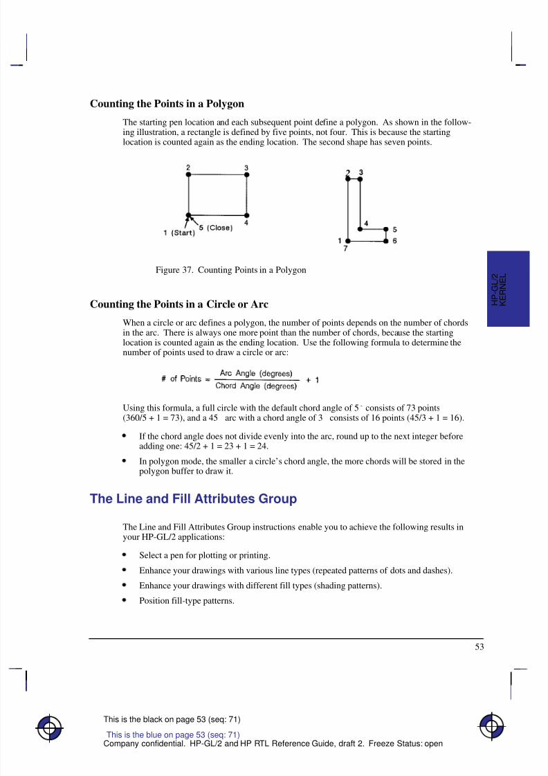
8/12/2019 HPGL2-RTL ReferenceGuide 5961-3526 540pages Sep96
http://slidepdf.com/reader/full/hpgl2-rtl-referenceguide-5961-3526-540pages-sep96 71/539
53
This is the black on page 53 (seq: 71)
Company confidential. HP-GL/2 and HP RTL Reference Guide, draft 2. Freeze Status: open
Counting the Points in a Polygon
The starting pen location and each subsequent point define a polygon. As shown in the follow-
ing illustration, a rectangle is defined by five points, not four. This is because the startinglocation is counted again as the ending location. The second shape has seven points.
Figure 37. Counting Points in a Polygon
Counting the Points in a Circle or Arc
When a circle or arc defines a polygon, the number of points depends on the number of chordsin the arc. There is always one more point than the number of chords, because the startinglocation is counted again as the ending location. Use the following formula to determine thenumber of points used to draw a circle or arc:
Using this formula, a full circle with the default chord angle of 5 consists of 73 points(360/5 + 1 = 73), and a 45 arc with a chord angle of 3 consists of 16 points (45/3 + 1 = 16).
If the chord angle does not divide evenly into the arc, round up to the next integer beforeadding one: 45/2 + 1 = 23 + 1 = 24.
In polygon mode, the smaller a circle’s chord angle, the more chords will be stored in thepolygon buffer to draw it.
The Line and Fill Attributes Group
The Line and Fill Attributes Group instructions enable you to achieve the following results inyour HP-GL/2 applications:
Select a pen for plotting or printing.
Enhance your drawings with various line types (repeated patterns of dots and dashes).
Enhance your drawings with different fill types (shading patterns).
Position fill-type patterns.
This is the blue on page 53 (seq: 71)
K E R N E L
H P - G L / 2
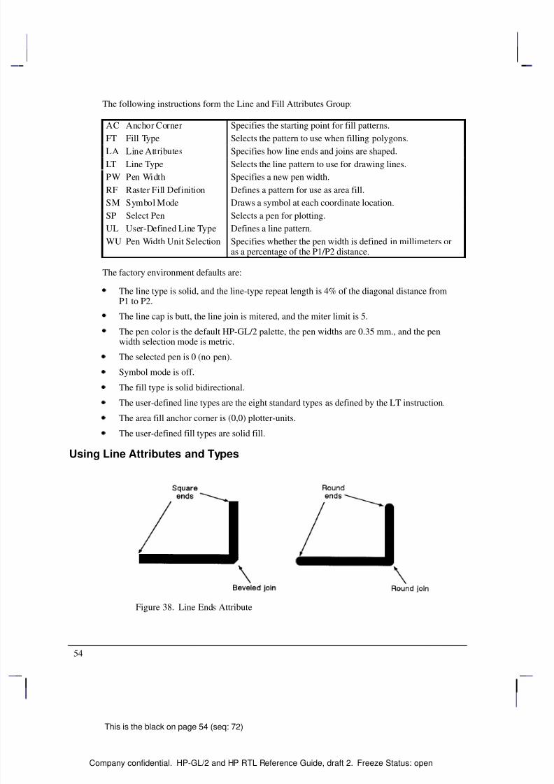
8/12/2019 HPGL2-RTL ReferenceGuide 5961-3526 540pages Sep96
http://slidepdf.com/reader/full/hpgl2-rtl-referenceguide-5961-3526-540pages-sep96 72/539
54
This is the black on page 54 (seq: 72)
Company confidential. HP-GL/2 and HP RTL Reference Guide, draft 2. Freeze Status: open
The following instructions form the Line and Fill Attributes Group:
Á Á Á Á Á Á Á Á Á
Á Á Á Á Á Á Á Á Á
AC Anchor Corner Á Á Á Á Á Á Á Á Á Á Á Á Á Á Á Á Á Á
Á Á Á Á Á Á Á Á Á Á Á Á Á Á Á Á Á Á
Specifies the starting point for fill patterns.
Á Á Á Á Á Á Á Á Á
Á Á Á Á Á Á Á Á Á
FT Fill Type Á Á Á Á Á Á Á Á Á Á Á Á Á Á Á Á Á Á
Á Á Á Á Á Á Á Á Á Á Á Á Á Á Á Á Á Á
Selects the pattern to use when filling polygons.
Á Á Á Á Á Á Á Á Á
Á Á Á Á Á Á Á Á Á
LA Line AttributesÁ Á Á Á Á Á Á Á Á Á Á Á Á Á Á Á Á Á
Á Á Á Á Á Á Á Á Á Á Á Á Á Á Á Á Á Á
Specifies how line ends and joins are shaped.
Á Á Á Á Á Á Á Á Á
Á Á Á Á Á Á Á Á Á
LT Line TypeÁ Á Á Á Á Á Á Á Á Á Á Á Á Á Á Á Á Á
Á Á Á Á Á Á Á Á Á Á Á Á Á Á Á Á Á Á
Selects the line pattern to use for drawing lines.Á Á Á Á Á Á Á Á Á
Á Á Á Á Á Á Á Á Á
PW Pen WidthÁ Á Á Á Á Á Á Á Á Á Á Á Á Á Á Á Á Á
Á Á Á Á Á Á Á Á Á Á Á Á Á Á Á Á Á Á
Specifies a new pen width.Á Á Á Á Á Á Á Á Á
Á Á Á Á Á Á Á Á Á
RF Raster Fill DefinitionÁ Á Á Á Á Á Á Á Á Á Á Á Á Á Á Á Á Á
Á Á Á Á Á Á Á Á Á Á Á Á Á Á Á Á Á Á
Defines a pattern for use as area fill.Á Á Á Á Á Á Á Á Á
Á Á Á Á Á Á Á Á Á
SM Symbol ModeÁ Á Á Á Á Á Á Á Á Á Á Á Á Á Á Á Á Á
Á Á Á Á Á Á Á Á Á Á Á Á Á Á Á Á Á Á
Draws a symbol at each coordinate location.Á Á Á Á Á Á Á Á Á
Á Á Á Á Á Á Á Á Á
SP Select PenÁ Á Á Á Á Á Á Á Á Á Á Á Á Á Á Á Á Á
Á Á Á Á Á Á Á Á Á Á Á Á Á Á Á Á Á Á
Selects a pen for plotting.Á Á Á Á Á Á Á Á Á
Á Á Á Á Á Á Á Á Á
UL User-Defined Line TypeÁ Á Á Á Á Á Á Á Á Á Á Á Á Á Á Á Á Á
Á Á Á Á Á Á Á Á Á Á Á Á Á Á Á Á Á Á
Defines a line pattern.Á Á Á Á Á Á Á Á Á
Á Á Á Á Á Á Á Á Á
Á Á Á Á Á Á Á Á Á
WU Pen Width Unit SelectionÁ Á Á Á Á Á Á Á Á Á Á Á Á Á Á Á Á Á
Á
Á Á Á Á Á Á Á Á Á Á Á Á Á Á Á Á Á
Á Á Á Á Á Á Á Á Á Á Á Á Á Á Á Á Á Á
Specifies whether the pen width is defined in millimeters oras a percentage of the P1/P2 distance.
The factory environment defaults are:
The line type is solid, and the line-type repeat length is 4% of the diagonal distance fromP1 to P2.
The line cap is butt, the line join is mitered, and the miter limit is 5.
The pen color is the default HP-GL/2 palette, the pen widths are 0.35 mm., and the penwidth selection mode is metric.
The selected pen is 0 (no pen).
Symbol mode is off.
The fill type is solid bidirectional.
The user-defined line types are the eight standard types as defined by the LT instruction.
The area fill anchor corner is (0,0) plotter-units.
The user-defined fill types are solid fill.
Using Line Attributes and Types
Figure 38. Line Ends Attribute
8/12/2019 HPGL2-RTL ReferenceGuide 5961-3526 540pages Sep96
http://slidepdf.com/reader/full/hpgl2-rtl-referenceguide-5961-3526-540pages-sep96 73/539
55
This is the black on page 55 (seq: 73)
Company confidential. HP-GL/2 and HP RTL Reference Guide, draft 2. Freeze Status: open
You can change the appearance of the lines you draw by using the LA (Line Attribute) and LT(Line Type) instructions. The LA instruction lets you specify whether the ends of lines andcorners of joined lines should appear as square, triangular, round, or beveled.
Line types are repeated patterns of dots and/or dashes (including solid lines). The followingshows some examples of line types. You can also vary the width of the lines and line types youdraw by using the PW (Pen Width) instruction. Note that the pen widths used in labels are de-termined by the stroke weight, specified in the AD and SD instructions.
Figure 39. Different Pen Widths and Line Types
Once you specify a line type and line attributes, all lines created by the following instructionsare drawn using the new line type and attributes. Line types and their interactions with fill pat-terns are discussed on page 56.
Instructions Affected by Line Types
AA Arc AbsoluteAR Arc RelativeAT Absolute Arc Three PointBR Bezier Relative
BZ Bezier AbsoluteCI CircleEA Edge Rectangle AbsoluteEP Edge PolygonER Edge Rectangle RelativeEW Edge WedgeFP Fill PolygonPA Plot AbsolutePD Pen DownPE Polyline EncodedPR Plot RelativeRA Fill Rectangle AbsoluteRR Fill Rectangle RelativeRT Relative Arc Three Point
WG Fill Wedge
K E R N E L
H P - G L / 2
This is the blue on page 55 (seq: 73)
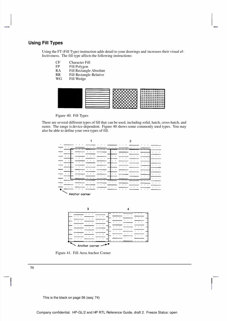
8/12/2019 HPGL2-RTL ReferenceGuide 5961-3526 540pages Sep96
http://slidepdf.com/reader/full/hpgl2-rtl-referenceguide-5961-3526-540pages-sep96 74/539
56
This is the black on page 56 (seq: 74)
Company confidential. HP-GL/2 and HP RTL Reference Guide, draft 2. Freeze Status: open
Using Fill Types
Using the FT (Fill Type) instruction adds detail to your drawings and increases their visual ef-
fectiveness. The fill type affects the following instructions:
CF Character FillFP Fill PolygonRA Fill Rectangle AbsoluteRR Fill Rectangle RelativeWG Fill Wedge
Figure 40. Fill Types
There are several different types of fill that can be used, including solid, hatch, cross-hatch, andraster. The range is device-dependent. Figure 40 shows some commonly used types. You mayalso be able to define your own types of fill.
Figure 41. Fill Area Anchor Corner
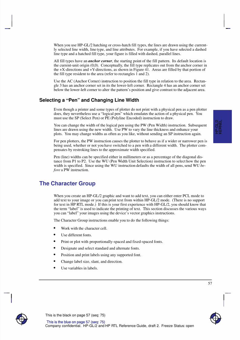
8/12/2019 HPGL2-RTL ReferenceGuide 5961-3526 540pages Sep96
http://slidepdf.com/reader/full/hpgl2-rtl-referenceguide-5961-3526-540pages-sep96 75/539
57
This is the black on page 57 (seq: 75)
Company confidential. HP-GL/2 and HP RTL Reference Guide, draft 2. Freeze Status: open
When you use HP-GL/2 hatching or cross-hatch fill types, the lines are drawn using the current-ly selected line width, line type, and line attributes. For example, if you have selected a dashedline type and a hatched fill type, your figure is filled with dashed, parallel lines.
All fill types have an anchor corner, the starting point of the fill pattern. Its default location isthe current-unit origin (0,0). Conceptually, the fill type replicates out from the anchor corner inthe +X-directions and +Y-directions, as shown in Figure 41. Areas are filled by that portion of the fill type resident to the area (refer to rectangles 1 and 2).
Use the AC (Anchor Corner) instruction to position the fill type in relation to the area. Rectan-gle 3 has an anchor corner set in its the lower-left corner. Rectangle 4 has an anchor corner setbelow the lower-left corner to alter the pattern’s position and give contrast to the adjacent area.
Selecting a “Pen” and Changing Line Width
Even though a printer and some types of plotter do not print with a physical pen as a pen plotterdoes, they nevertheless use a “logical pen” which emulates the action of a physical pen. You
must use the SP (Select Pen) or PE (Polyline Encoded) instruction to draw.You can change the width of the logical pen using the PW (Pen Width) instruction. Subsequentlines are drawn using the new width. Use PW to vary the line thickness and enhance yourplots. You may change widths as often as you like, without sending an SP instruction again.
For pen plotters, the PW instruction causes the plotter to behave as if a wider or narrower pen isbeing used, whether or not you have switched to a pen with a different width. The plotter com-pensates by restroking lines to the approximate width specified.
Pen (line) widths can be specified either in millimeters or as a percentage of the diagonal dis-tance from P1 to P2. Use the WU (Pen Width Unit Selection) instruction to select how the penwidth is specified. Since using the WU instruction defaults the width of all pens, send WU be-
fore a PW instruction.
The Character Group
When you create an HP-GL/2 graphic and want to add text, you can either enter PCL mode toadd text to your image or you can print text from within HP-GL/2 mode. (There is no supportfor text in HP RTL mode.) If this is your first experience with HP-GL/2, you should know thatthe term “label” is used to indicate the printing of text. This section discusses the various waysyou can “label” your images using the device’s vector graphics instructions.
The Character Group instructions enable you to do the following things:
Work with the character cell.
Use different fonts.
Print or plot with proportionally-spaced and fixed-spaced fonts.
Designate and select standard and alternate fonts.
Position and print labels using any supported font.
Change label size, slant, and direction.
Use variables in labels.
This is the blue on page 57 (seq: 75)
K E R N E L
H P - G L / 2
This is the blue on page 57 (seq: 75)
8/12/2019 HPGL2-RTL ReferenceGuide 5961-3526 540pages Sep96
http://slidepdf.com/reader/full/hpgl2-rtl-referenceguide-5961-3526-540pages-sep96 76/539
58
This is the black on page 58 (seq: 76)
Company confidential. HP-GL/2 and HP RTL Reference Guide, draft 2. Freeze Status: open
The following instructions form the Character Group:
Á Á Á Á Á Á Á Á Á
Á Á Á Á Á Á Á Á Á
AD Alternate Font DefinitionÁ Á Á Á Á Á Á Á Á Á Á Á Á Á Á Á Á Á
Á Á Á Á Á Á Á Á Á Á Á Á Á Á Á Á Á Á
Specifies an alternate font for labeling.
Á Á Á Á Á Á Á Á Á
Á Á Á Á Á Á Á Á Á
CF Character Fill Mode Á Á Á Á Á Á Á Á Á Á Á Á Á Á Á Á Á Á
Á Á Á Á Á Á Á Á Á Á Á Á Á Á Á Á Á Á
Specifies how outline fonts are rendered.
Á Á Á Á Á Á Á Á Á
Á Á Á Á Á Á Á Á Á
CP Character PlotÁ Á Á Á Á Á Á Á Á Á Á Á Á Á Á Á Á Á
Á Á Á Á Á Á Á Á Á Á Á Á Á Á Á Á Á Á
Moves the pen the specified number of character cells fromthe current pen location.
Á Á Á Á Á Á Á Á Á
Á Á Á Á Á Á Á Á Á
Á Á Á Á Á Á Á Á Á
DI Absolute DirectionÁ Á Á Á Á Á Á Á Á Á Á Á Á Á Á Á Á Á
Á Á Á Á Á Á Á Á Á Á Á Á Á Á Á Á Á Á
Á Á Á Á Á Á Á Á Á Á Á Á Á Á Á Á Á Á
Specifies the slope of labels independent of P1 and P2 loca-tions.
Á Á Á Á Á Á Á Á Á
Á Á Á Á Á Á Á Á Á
DR Relative Direction Á Á Á Á Á Á Á Á Á Á Á Á Á Á Á Á Á Á
Á Á Á Á Á Á Á Á Á Á Á Á Á Á Á Á Á Á
Specifies the slope of labels relative to P1 and P2 locations.
Á Á Á Á Á Á Á Á Á
Á Á Á Á Á Á Á Á Á
DT Define Label TerminatorÁ Á Á Á Á Á Á Á Á Á Á Á Á Á Á Á Á Á
Á Á Á Á Á Á Á Á Á Á Á Á Á Á Á Á Á Á
Defines the character or code that “turns off” labeling.
Á Á Á Á Á Á Á Á Á
Á Á Á Á Á Á Á Á Á
DV Define Variable TextPath
Á Á Á Á Á Á Á Á Á Á Á Á Á Á Á Á Á Á
Á Á Á Á Á Á Á Á Á Á Á Á Á Á Á Á Á Á
Specifies the label path as right, left, up, or down.
Á Á Á Á Á Á Á Á Á
Á Á Á Á Á Á Á Á Á
Á Á Á Á Á Á Á Á Á
ES Extra SpaceÁ Á Á Á Á Á Á Á Á Á Á Á Á Á Á Á Á Á
Á
Á Á Á Á Á Á Á Á Á Á Á Á Á Á Á Á Á
Á Á Á Á Á Á Á Á Á Á Á Á Á Á Á Á Á Á
Increases or reduces space between label characters andlines.
Á Á Á Á Á Á Á Á Á
Á Á Á Á Á Á Á Á Á
LB Label Á Á Á Á Á Á Á Á Á Á Á Á Á Á Á Á Á Á
Á Á Á Á Á Á Á Á Á Á Á Á Á Á Á Á Á Á
Prints text using the currently selected font.
Á Á Á Á Á Á Á Á Á
Á Á Á Á Á Á Á Á Á
LO Label OriginÁ Á Á Á Á Á Á Á Á Á Á Á Á Á Á Á Á Á
Á Á Á Á Á Á Á Á Á Á Á Á Á Á Á Á Á Á
Positions labels relative to the current pen location.
Á Á Á Á Á Á Á Á Á
Á Á Á Á Á Á Á Á Á
SA Select Alternate FontÁ Á Á Á Á Á Á Á Á Á Á Á Á Á Á Á Á Á
Á Á Á Á Á Á Á Á Á Á Á Á Á Á Á Á Á Á
Selects the font designated by AD for labeling.
Á Á Á Á Á Á Á Á Á
Á Á Á Á Á Á Á Á Á
SD Standard Font DefinitionÁ Á Á Á Á Á Á Á Á Á Á Á Á Á Á Á Á Á
Á Á Á Á Á Á Á Á Á Á Á Á Á Á Á Á Á Á
Specifies the standard font for labeling.
Á Á Á Á Á Á Á Á Á
SI Absolute Character SizeÁ Á Á Á Á Á Á Á Á Á Á Á Á Á Á Á Á Á
Specifies an absolute character size (in centimeters).Á Á Á Á Á Á Á Á Á
Á Á Á Á Á Á Á Á Á
SL Character SlantÁ Á Á Á Á Á Á Á Á Á Á Á Á Á Á Á Á Á
Á Á Á Á Á Á Á Á Á Á Á Á Á Á Á Á Á Á
Specifies the slant at which labels are printed.Á Á Á Á Á Á Á Á Á
Á Á Á Á Á Á Á Á Á
Á Á Á Á Á Á Á Á Á
SR Relative Character SizeÁ Á Á Á Á Á Á Á Á Á Á Á Á Á Á Á Á Á
Á
Á Á Á Á Á Á Á Á Á Á Á Á Á Á Á Á Á
Á Á Á Á Á Á Á Á Á Á Á Á Á Á Á Á Á Á
Specifies the size of characters as a percentage of the P1/P2distance.
Á Á Á Á Á Á Á Á Á
Á Á Á Á Á Á Á Á Á
SS Select Standard Font Á Á Á Á Á Á Á Á Á Á Á Á Á Á Á Á Á Á
Á Á Á Á Á Á Á Á Á Á Á Á Á Á Á Á Á Á
Selects the font designated by SD for labeling.
Á Á Á Á Á Á Á Á Á
Á Á Á Á Á Á Á Á Á
TD Transparent DataÁ Á Á Á Á Á Á Á Á Á Á Á Á Á Á Á Á Á
Á
Á Á Á Á Á Á Á Á Á Á Á Á Á Á Á Á Á
Specifies whether control characters perform their normalfunction or are printed as characters when printing text.
Working with the Character Cell
In each font, the basis for each character or space is the character cell. Think of the charactercell as a rectangular area around a character that includes blank areas above and to the right of the character. Refer to Figure 42 and the following explanations of some terms.
Baseline—The imaginary line on which a line of text rests. A character’s descender (such asthe bottom of a lowercase “g”) extends below the baseline.
Line Feed —The distance from the baseline of a line of text to the baseline of the next characterline above or below. For most fonts, the linefeed is about 1.2 times the point size (1.33 timesthe point size for stick fonts).
Point Size—Traditional character measure roughly equivalent to the height of a capital letter M
plus the depth of a descender. Point size is usually measured in units of 1/72-inch.
Delta-X —The implied pen movement that occurs after a character is printed. It includes thespace taken up by the character as well as the white space between the characters set by the ES(Extra Space) instruction. In a fixed-spaced font, delta-X is the same for every character. In a
proportionally-spaced font, delta-X varies from one character to another.
Pitch—The number of characters per inch. It is the inverse of delta-X. A pitch of 10 meansthat the delta-X is one-tenth of an inch; ten characters will fit into a one-inch space. Pitch is
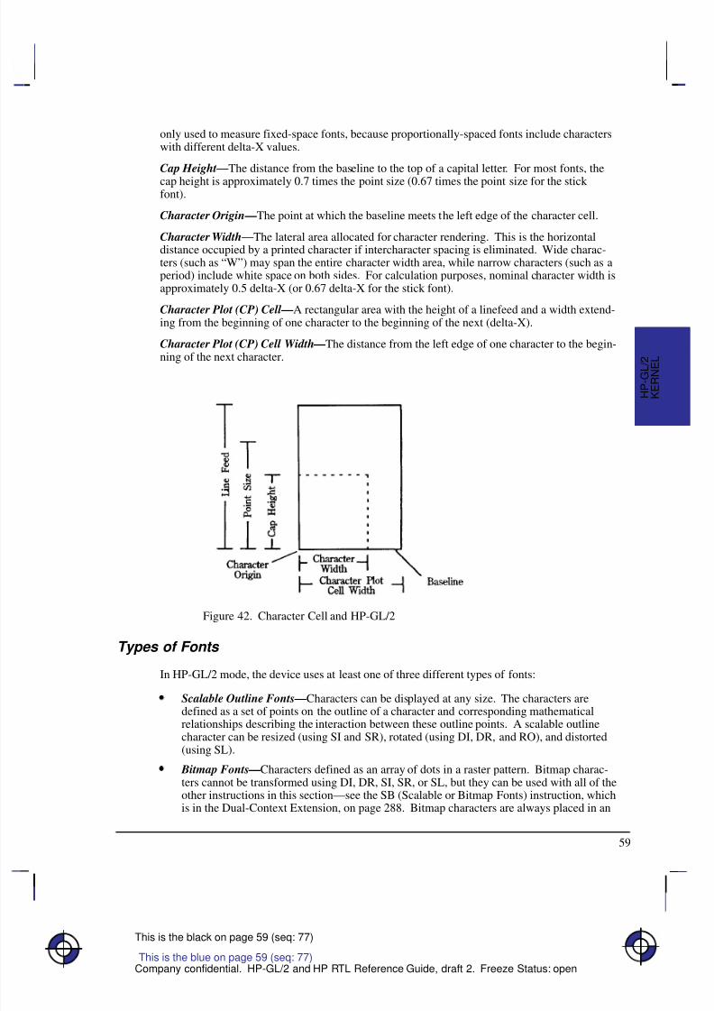
8/12/2019 HPGL2-RTL ReferenceGuide 5961-3526 540pages Sep96
http://slidepdf.com/reader/full/hpgl2-rtl-referenceguide-5961-3526-540pages-sep96 77/539
59
This is the black on page 59 (seq: 77)
Company confidential. HP-GL/2 and HP RTL Reference Guide, draft 2. Freeze Status: open
only used to measure fixed-space fonts, because proportionally-spaced fonts include characterswith different delta-X values.
Cap Height—The distance from the baseline to the top of a capital letter. For most fonts, thecap height is approximately 0.7 times the point size (0.67 times the point size for the stick font).
Character Origin—The point at which the baseline meets the left edge of the character cell.
Character Width—The lateral area allocated for character rendering. This is the horizontaldistance occupied by a printed character if intercharacter spacing is eliminated. Wide charac-ters (such as “W”) may span the entire character width area, while narrow characters (such as aperiod) include white space on both sides. For calculation purposes, nominal character width isapproximately 0.5 delta-X (or 0.67 delta-X for the stick font).
Character Plot (CP) Cell —A rectangular area with the height of a linefeed and a width extend-ing from the beginning of one character to the beginning of the next (delta-X).
Character Plot (CP) Cell Width—The distance from the left edge of one character to the begin-
ning of the next character.
Figure 42. Character Cell and HP-GL/2
Types of Fonts
In HP-GL/2 mode, the device uses at least one of three different types of fonts:
Scalable Outline Fonts—Characters can be displayed at any size. The characters are
defined as a set of points on the outline of a character and corresponding mathematicalrelationships describing the interaction between these outline points. A scalable outlinecharacter can be resized (using SI and SR), rotated (using DI, DR, and RO), and distorted(using SL).
Bitmap Fonts—Characters defined as an array of dots in a raster pattern. Bitmap charac-ters cannot be transformed using DI, DR, SI, SR, or SL, but they can be used with all of theother instructions in this section—see the SB (Scalable or Bitmap Fonts) instruction, whichis in the Dual-Context Extension, on page 288. Bitmap characters are always placed in an
This is the blue on page 59 (seq: 77)
K E R N E L
H P - G L / 2
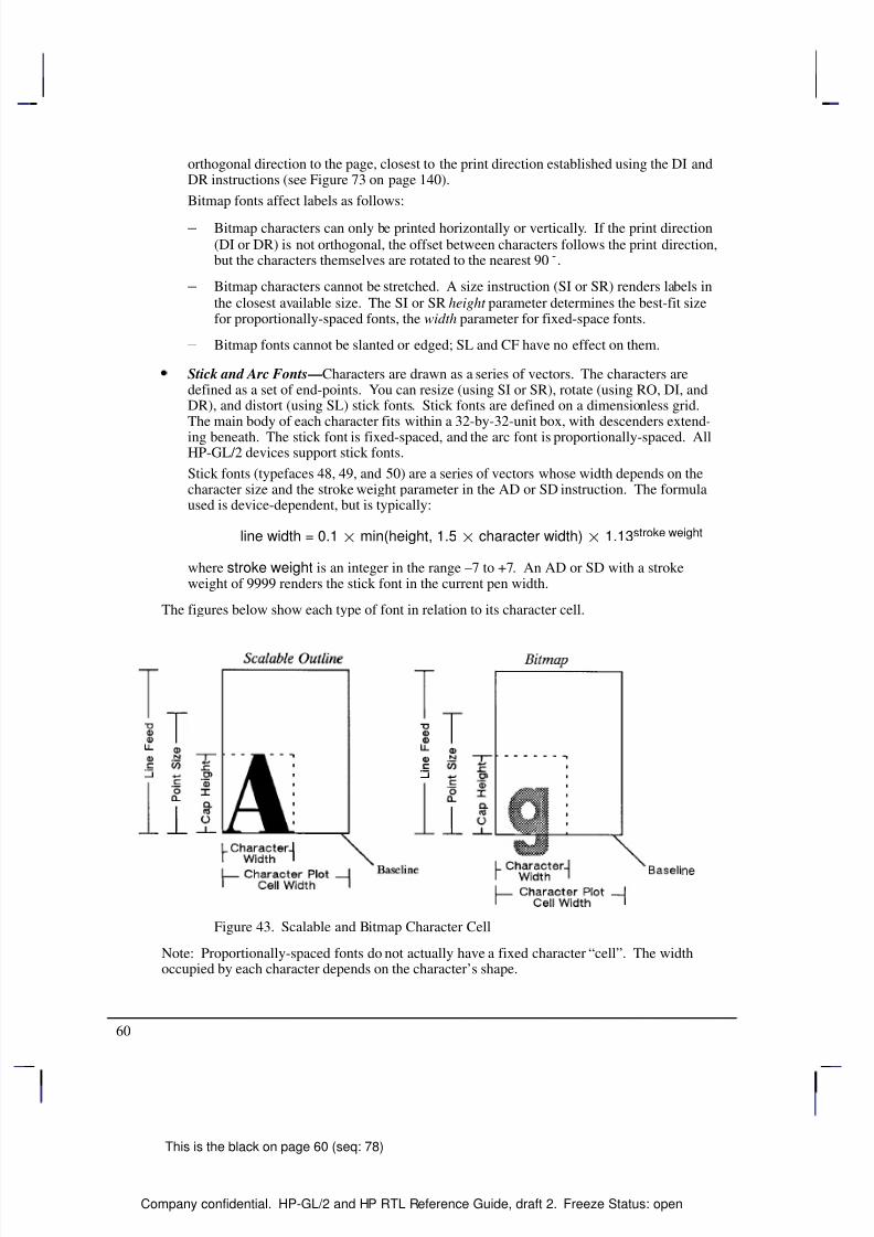
8/12/2019 HPGL2-RTL ReferenceGuide 5961-3526 540pages Sep96
http://slidepdf.com/reader/full/hpgl2-rtl-referenceguide-5961-3526-540pages-sep96 78/539
60
This is the black on page 60 (seq: 78)
Company confidential. HP-GL/2 and HP RTL Reference Guide, draft 2. Freeze Status: open
orthogonal direction to the page, closest to the print direction established using the DI andDR instructions (see Figure 73 on page 140).
Bitmap fonts affect labels as follows:
– Bitmap characters can only be printed horizontally or vertically. If the print direction(DI or DR) is not orthogonal, the offset between characters follows the print direction,but the characters themselves are rotated to the nearest 90.
– Bitmap characters cannot be stretched. A size instruction (SI or SR) renders labels inthe closest available size. The SI or SR height parameter determines the best-fit sizefor proportionally-spaced fonts, the width parameter for fixed-space fonts.
– Bitmap fonts cannot be slanted or edged; SL and CF have no effect on them.
Stick and Arc Fonts—Characters are drawn as a series of vectors. The characters aredefined as a set of end-points. You can resize (using SI or SR), rotate (using RO, DI, andDR), and distort (using SL) stick fonts. Stick fonts are defined on a dimensionless grid.The main body of each character fits within a 32-by-32-unit box, with descenders extend-
ing beneath. The stick font is fixed-spaced, and the arc font is proportionally-spaced. AllHP-GL/2 devices support stick fonts.
Stick fonts (typefaces 48, 49, and 50) are a series of vectors whose width depends on thecharacter size and the stroke weight parameter in the AD or SD instruction. The formulaused is device-dependent, but is typically:
line width = 0.1 min(height, 1.5 character width) 1.13stroke weight
where stroke weight is an integer in the range –7 to +7. An AD or SD with a strokeweight of 9999 renders the stick font in the current pen width.
The figures below show each type of font in relation to its character cell.
Figure 43. Scalable and Bitmap Character Cell
Note: Proportionally-spaced fonts do not actually have a fixed character “cell”. The widthoccupied by each character depends on the character’s shape.
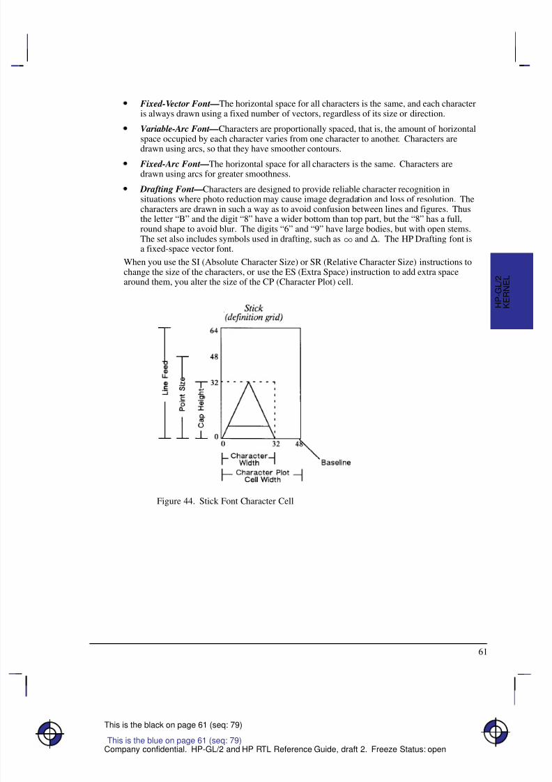
8/12/2019 HPGL2-RTL ReferenceGuide 5961-3526 540pages Sep96
http://slidepdf.com/reader/full/hpgl2-rtl-referenceguide-5961-3526-540pages-sep96 79/539
61
This is the black on page 61 (seq: 79)
Company confidential. HP-GL/2 and HP RTL Reference Guide, draft 2. Freeze Status: open
Fixed-Vector Font—The horizontal space for all characters is the same, and each characteris always drawn using a fixed number of vectors, regardless of its size or direction.
Variable-Arc Font—Characters are proportionally spaced, that is, the amount of horizontal
space occupied by each character varies from one character to another. Characters aredrawn using arcs, so that they have smoother contours.
Fixed-Arc Font—The horizontal space for all characters is the same. Characters aredrawn using arcs for greater smoothness.
Drafting Font—Characters are designed to provide reliable character recognition insituations where photo reduction may cause image degradation and loss of resolution. Thecharacters are drawn in such a way as to avoid confusion between lines and figures. Thusthe letter “B” and the digit “8” have a wider bottom than top part, but the “8” has a full,round shape to avoid blur. The digits “6” and “9” have large bodies, but with open stems.The set also includes symbols used in drafting, such as and . The HP Drafting font isa fixed-space vector font.
When you use the SI (Absolute Character Size) or SR (Relative Character Size) instructions to
change the size of the characters, or use the ES (Extra Space) instruction to add extra spacearound them, you alter the size of the CP (Character Plot) cell.
Figure 44. Stick Font Character Cell
K E R N E L
H P - G L / 2
This is the blue on page 61 (seq: 79)
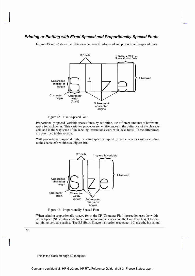
8/12/2019 HPGL2-RTL ReferenceGuide 5961-3526 540pages Sep96
http://slidepdf.com/reader/full/hpgl2-rtl-referenceguide-5961-3526-540pages-sep96 80/539
62
This is the black on page 62 (seq: 80)
Company confidential. HP-GL/2 and HP RTL Reference Guide, draft 2. Freeze Status: open
Printing or Plotting with Fixed-Spaced and Proportionally-Spaced Fonts
Figures 45 and 46 show the difference between fixed-spaced and proportionally-spaced fonts.
Figure 45. Fixed-Spaced Font
Proportionally-spaced (variable-space) fonts, by definition, use different amounts of horizontalspace for each letter. This variation produces some differences in the definition of the charactercell, and in the way some of the labeling instructions work with these fonts. These differencesare described in this section.
With proportionally-spaced fonts, the actual space occupied by each character varies accordingto the character’s width (see Figure 46).
Figure 46. Proportionally-Spaced Font
When printing proportionally-spaced fonts, the CP (Character Plot) instruction uses the widthof the Space () control code to determine horizontal spaces and the Line Feed height for de-termining vertical spacing. The ES (Extra Space) instruction (see page 169) uses the horizontal
8/12/2019 HPGL2-RTL ReferenceGuide 5961-3526 540pages Sep96
http://slidepdf.com/reader/full/hpgl2-rtl-referenceguide-5961-3526-540pages-sep96 81/539
63
This is the black on page 63 (seq: 81)
Company confidential. HP-GL/2 and HP RTL Reference Guide, draft 2. Freeze Status: open
escapement distance (a font metric) to compute horizontal spaces and the Line Feed height fordetermining vertical spacing. Both of the character size instructions (SI and SR) use cap heightand average character width in calculating character size. Otherwise, these instructions behave
the same as they do with fixed-spaced fonts.
Designating and Selecting Fonts
If you intend to label with the default fixed-spaced (stick) font, you do not need to use the SDor AD instructions for designating standard and alternate fonts. However, if you intend to use adifferent font (for example, to match accompanying PCL text), you must use the SD or ADinstructions to designate fonts before you can select those fonts for labeling (using either SA orSS).
Standard and Alternate Fonts
The following outlines some of the principles to use when labeling with different fonts:
Designate the standard and alternate fonts using the SD or AD instruction before labeling.If you are using the stick font (the default) as your standard font, you need specify onlyyour alternate font.
Select either the standard or alternate font, using either the SS or SA instruction beforelabeling.
Note that labeling always begins with the standard font, unless you use the SA instructionbefore you begin your label (or finish the previous label in the alternate font).
Switch from the standard font to the alternate font, either using SS and SA or the ShiftIn/Shift Out method. If you are changing fonts within a text string, the Shift In/Shift Outmethod is usually more efficient. See Accessing Special Characters on page 72. Switchfrom the standard font to the alternate font using the ASCII Shift Out control character (,
decimal code 14). Switch from the alternate font to the standard font using the ASCII ShiftIn control character (, decimal code 15). (Note that a Shift In () or Shift Out ()outside of the label instruction string is ignored.)
How Your Device Selects Fonts
The following summarizes the procedure that your device follows to select a font. The criteriaare based on the parameters of the AD and SD instructions. The procedure is necessary be-cause fixed-space and variable-space fonts use different criteria to determine text size. Forfixed-space fonts, the pitch determines the size. The height parameter of the AD and SDinstructions is only used to distinguish between fonts with equal pitch. For variable-spacefonts, the height parameter of the AD and SD instructions determines the text size; the pitchparameter is ignored. Your HP-GL/2 device performs the following steps in order:
1. If the specified character set does not exist, the device uses the user default set (set fromthe control panel, if there is one) or the factory default set.
2. If the specified font spacing (fixed or variable) is available, it is used; otherwise the deviceuses the remaining space option.
3. If the remaining fonts are proportionally spaced, the pitch is ignored. For fixed-spacefonts, if the specified pitch is not available, the device selects the next greater pitch. If nogreater pitch is available, the device selects the closest available smaller pitch. (A pitch of
This is the blue on page 63 (seq: 81)
K E R N E L
H P - G L / 2
8/12/2019 HPGL2-RTL ReferenceGuide 5961-3526 540pages Sep96
http://slidepdf.com/reader/full/hpgl2-rtl-referenceguide-5961-3526-540pages-sep96 82/539
64
This is the black on page 64 (seq: 82)
Company confidential. HP-GL/2 and HP RTL Reference Guide, draft 2. Freeze Status: open
12 characters per inch [cpi] is greater than one of 10 cpi; greater pitch means smaller char-acters.) Note that any specified pitch is available for scalable fonts.
4. The device selects the closest available height to the height parameter. The closest avail-able height is in terms of absolute difference. For example, if the device has 6-, 8-, and12-point fonts and the specified height is 10, both 8- and 12-point fonts are selected for thenext selection criterion. All fonts with heights within a quarter-point of the specifiedheight are considered to satisfy the height criteria. Note that any specified height is avail-able for scalable fonts. Height is ignored for fixed-space fonts.
5. If the specified posture (upright or italic) is available in the remaining fonts, the deviceselects that posture; otherwise, this attribute is ignored.
6. If the specified stroke weight is available in the remaining fonts, the device selects thatstroke weight. Note that any stroke weight is available for stick fonts.
If the specified stroke weight is greater than or equal to zero and is not available, thedevice selects the next thicker stroke weight. If no thicker stroke weight is available,
the device selects the next thinner stroke weight.
If the specified stroke weight is less than zero and is not available, the device selectsthe next thinner stroke weight. If no thinner stroke weight is available, the device se-lects the next thicker stroke weight.
7. If the specified typeface is available, the device selects that typeface; otherwise, the deviceignores this attribute. The stick fonts are typefaces 48, 49, and 50. The character set andposture selections must match an available stick font.
8. If more than one font emerges after this procedure, the location of fonts provides the fol-lowing order of priority:
Downloaded bitmap soft fonts in ascending font ID order.
Downloaded scalable soft fonts in ascending font ID order.Bitmap external cartridge fonts.
Scalable external cartridge fonts.
Bitmap internal fonts.
Scalable internal fonts.
9. If multiple fonts remain, a font in the specified orientation (the result of the DI or DRinstruction) is selected. If none of the fonts is defined in the specified orientation, automat-ic rotation is applied to one of the remaining fonts.
Using Labels
Use the LB (Label) instruction to add text to plots, to create text charts, or to emphasize areasof a diagram or graph that need special attention or explanation. You can control almost allaspects of the label’s appearance: its position, size, slant, spacing, and direction. All labels aredrawn using the font currently designated (refer to the SD or AD instructions) and selected foruse (refer to the SS or SA instructions).
If you are using a font other than the default, use SD (Standard Font Definition) or AD (Alter-nate Font Definition) instructions to designate a font. Then, use the SS (Select Standard Font)or SA (Select Alternate Font) instructions to select the designated font for use. You can follow
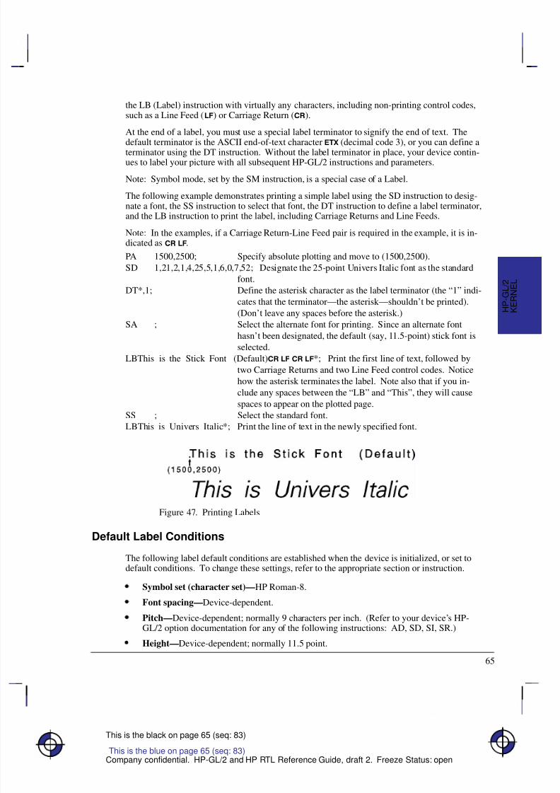
8/12/2019 HPGL2-RTL ReferenceGuide 5961-3526 540pages Sep96
http://slidepdf.com/reader/full/hpgl2-rtl-referenceguide-5961-3526-540pages-sep96 83/539
65
This is the black on page 65 (seq: 83)
Company confidential. HP-GL/2 and HP RTL Reference Guide, draft 2. Freeze Status: open
the LB (Label) instruction with virtually any characters, including non-printing control codes,such as a Line Feed () or Carriage Return ().
At the end of a label, you must use a special label terminator to signify the end of text. Thedefault terminator is the ASCII end-of-text character (decimal code 3), or you can define aterminator using the DT instruction. Without the label terminator in place, your device contin-ues to label your picture with all subsequent HP-GL/2 instructions and parameters.
Note: Symbol mode, set by the SM instruction, is a special case of a Label.
The following example demonstrates printing a simple label using the SD instruction to desig-nate a font, the SS instruction to select that font, the DT instruction to define a label terminator,and the LB instruction to print the label, including Carriage Returns and Line Feeds.
Note: In the examples, if a Carriage Return-Line Feed pair is required in the example, it is in-dicated as .
PA 1500,2500; Specify absolute plotting and move to (1500,2500).
SD 1,21,2,1,4,25,5,1,6,0,7,52; Designate the 25-point Univers Italic font as the standard
font.DT*,1; Define the asterisk character as the label terminator (the “1” indi-
cates that the terminator—the asterisk—shouldn’t be printed).
(Don’t leave any spaces before the asterisk.)
SA ; Select the alternate font for printing. Since an alternate font
hasn’t been designated, the default (say, 11.5-point) stick font is
selected.
LBThis is the Stick Font (Default) *; Print the first line of text, followed by
two Carriage Returns and two Line Feed control codes. Notice
how the asterisk terminates the label. Note also that if you in-
clude any spaces between the “LB” and “This”, they will cause
spaces to appear on the plotted page.
SS ; Select the standard font.LBThis is Univers Italic*; Print the line of text in the newly specified font.
Figure 47. Printing Labels
Default Label Conditions
The following label default conditions are established when the device is initialized, or set todefault conditions. To change these settings, refer to the appropriate section or instruction.
Symbol set (character set)—HP Roman-8.
Font spacing—Device-dependent.
Pitch—Device-dependent; normally 9 characters per inch. (Refer to your device’s HP-GL/2 option documentation for any of the following instructions: AD, SD, SI, SR.)
Height—Device-dependent; normally 11.5 point.
This is the blue on page 65 (seq: 83)
K E R N E L
H P - G L / 2
8/12/2019 HPGL2-RTL ReferenceGuide 5961-3526 540pages Sep96
http://slidepdf.com/reader/full/hpgl2-rtl-referenceguide-5961-3526-540pages-sep96 84/539
66
This is the black on page 66 (seq: 84)
Company confidential. HP-GL/2 and HP RTL Reference Guide, draft 2. Freeze Status: open
Posture—Device-dependent.
Stroke weight—Device-dependent.
Typeface—HP-GL/2 stick.(For each of the above settings, refer to the AD and SD [Alternate and Standard Font Defi-nition] instructions.)
Label terminator—ASCII end-of-text character (decimal code 3). Refer to the DT(Define Label Terminator) instruction.
Label starting point—Current pen location (LO1). Refer to the LO (Label Origin)instruction.
Label direction—Horizontal (the positive X-direction; it may be vertical on the paper).Refer to the DI, DR, and DV instructions.
Label direction mode—Absolute. Refer to the DI instruction.
Label size mode—Absolute. Refer to the SI instruction.Character width and height—Device-dependent. Refer to the SI instruction.
Space between characters and lines—Normal (no extra space). Refer to the ES (ExtraSpace) instruction.
Character slant—None (vertical). Refer to the SL (Character Slant) instruction.
Character fill mode—Solid fill, no edging. Refer to the CF (Character Fill Mode) instruc-tion.
Transparent data mode—Off. Refer to the TD instruction.
Character Positioning
LB uses the current pen position as the reference for the label position. LO (Label Origin) canleft-align, center, right-align, and adjust the vertical position about the current pen position.
The default label starting point is approximately at the intersection of the left edge of the char-acter and the baseline. After printing a character, the pen position is updated by that character’sdelta-X distance to the starting point of the next character (unless modified by ES). This con-tinues until the end of the label string (unless an embedded control character such as a carriagereturn or line feed is encountered). When printing the label, the pen position is updated accord-ing to the current path (DV) and label origin (LO). DV operates during the label, determiningthe character-to-character direction.
LB updates the pen position, but not the carriage-return point. characters move the carriage-return point down; DV changes this direction. The carriage-return point is maintained inphysical units, not user units.
Moving to the Carriage-Return Point
When you begin labeling, the current pen location is the carriage-return point (the beginningof your line of text is the point to which the pen is “returned” when a carriage return () con-trol code is sent to the device). When the device encounters a CP (Character Plot) instruction,or a carriage return control code within a Label instruction, the pen moves to the carriage-re-turn point, adjusted up or down by any line feeds.
8/12/2019 HPGL2-RTL ReferenceGuide 5961-3526 540pages Sep96
http://slidepdf.com/reader/full/hpgl2-rtl-referenceguide-5961-3526-540pages-sep96 85/539
67
This is the black on page 67 (seq: 85)
Company confidential. HP-GL/2 and HP RTL Reference Guide, draft 2. Freeze Status: open
The following instructions update the carriage-return point to the current location:
AA Arc AbsoluteAR Arc RelativeAT Absolute Arc (Three Point)BR Bezier RelativeBZ Bezier AbsoluteCP Character Plot (see note)DF Default ValuesDI Absolute DirectionDR Relative DirectionDV Define Variable Text PathIN InitializeLO Label OriginPA Plot AbsolutePD Pen Down (see note)PE Polyline Encoded
PR Plot RelativePU Pen Up (see note)RO Rotate Coordinate SystemRT Relative Arc (Three Point)
Note: A PD or PU instruction with parameters also updates the carriage-return point. The CPinstruction with a non-zero lines parameter updates the carriage-return point’s vertical location.
The LB (Label) instruction does not update the carriage-return point to the current pen location,but continues labeling from the current pen location. This feature allows you to issue severallabel instructions that write one long label and still use a to get to the beginning of the entirelabel.
Control Characters
There are two modes of operation for printing HP-GL/2 labels: normal and transparent data.
Normal mode is the default; all character codes within a label are printed using the currentlyselected font, undefined character codes produce a space, and all control codes are ignored un-less they perform a function, as follows (these are the codes in the PC-8 compatible symbolsets):
ControlCode
Decimalcode
Description
Null () 0 No Operation (NOP).
End-of-text( )
3 An indication of the end of a label. If an alternative labelterminator has been defined (using the DT instruction),
this code performs no operation (NOP).Bell() 7 No Operation (NOP).
Backspace()
8 The pen moves to the position before the last printedcharacter. For proportionally-spaced fonts, a backspacecenters the overstriking character on the overstruck char-acter; the pen position should end up at the same positionas before the backspace. A backspace as the first charac-ter of a label is ignored.
This is the blue on page 67 (seq: 85)
K E R N E L
H P - G L / 2
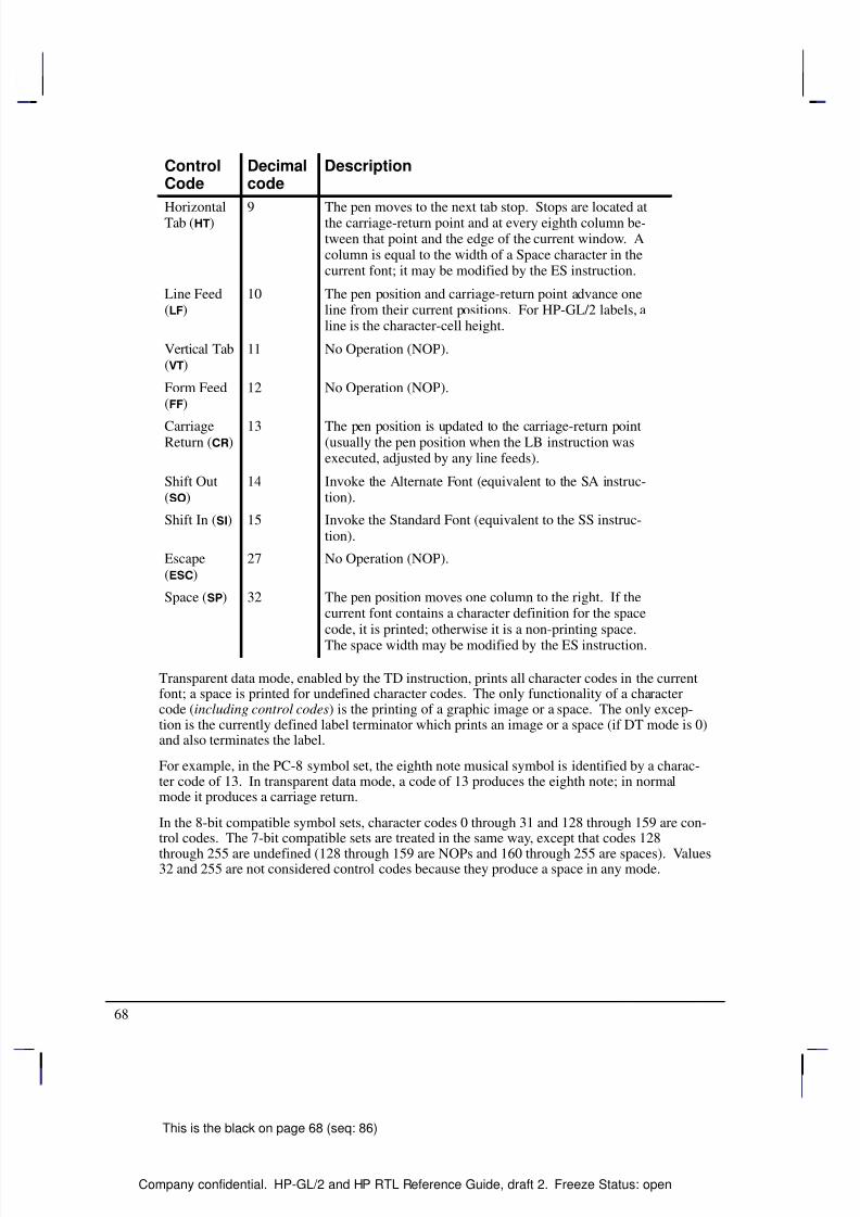
8/12/2019 HPGL2-RTL ReferenceGuide 5961-3526 540pages Sep96
http://slidepdf.com/reader/full/hpgl2-rtl-referenceguide-5961-3526-540pages-sep96 86/539
68
This is the black on page 68 (seq: 86)
Company confidential. HP-GL/2 and HP RTL Reference Guide, draft 2. Freeze Status: open
ControlCode
DescriptionDecimalcode
HorizontalTab () 9 The pen moves to the next tab stop. Stops are located atthe carriage-return point and at every eighth column be-tween that point and the edge of the current window. Acolumn is equal to the width of a Space character in thecurrent font; it may be modified by the ES instruction.
Line Feed()
10 The pen position and carriage-return point advance oneline from their current positions. For HP-GL/2 labels, aline is the character-cell height.
Vertical Tab( )
11 No Operation (NOP).
Form Feed()
12 No Operation (NOP).
CarriageReturn ()
13 The pen position is updated to the carriage-return point(usually the pen position when the LB instruction wasexecuted, adjusted by any line feeds).
Shift Out()
14 Invoke the Alternate Font (equivalent to the SA instruc-tion).
Shift In () 15 Invoke the Standard Font (equivalent to the SS instruc-tion).
Escape()
27 No Operation (NOP).
Space () 32 The pen position moves one column to the right. If thecurrent font contains a character definition for the spacecode, it is printed; otherwise it is a non-printing space.The space width may be modified by the ES instruction.
Transparent data mode, enabled by the TD instruction, prints all character codes in the currentfont; a space is printed for undefined character codes. The only functionality of a charactercode (including control codes) is the printing of a graphic image or a space. The only excep-tion is the currently defined label terminator which prints an image or a space (if DT mode is 0)and also terminates the label.
For example, in the PC-8 symbol set, the eighth note musical symbol is identified by a charac-ter code of 13. In transparent data mode, a code of 13 produces the eighth note; in normalmode it produces a carriage return.
In the 8-bit compatible symbol sets, character codes 0 through 31 and 128 through 159 are con-trol codes. The 7-bit compatible sets are treated in the same way, except that codes 128
through 255 are undefined (128 through 159 are NOPs and 160 through 255 are spaces). Values32 and 255 are not considered control codes because they produce a space in any mode.
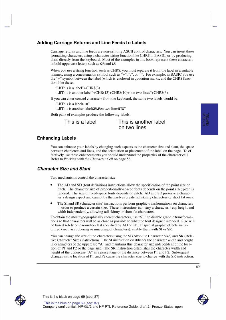
8/12/2019 HPGL2-RTL ReferenceGuide 5961-3526 540pages Sep96
http://slidepdf.com/reader/full/hpgl2-rtl-referenceguide-5961-3526-540pages-sep96 87/539
69
This is the black on page 69 (seq: 87)
Company confidential. HP-GL/2 and HP RTL Reference Guide, draft 2. Freeze Status: open
Adding Carriage Returns and Line Feeds to Labels
Carriage returns and line feeds are non-printing ASCII control characters. You can insert these
formatting characters using a character-string function like CHR$ in BASIC, or by producingthem directly from the keyboard. Most of the examples in this book represent these charactersin bold uppercase letters such as and .
When you use a string function such as CHR$, you must separate it from the label in a suitablemanner, using a concatenation symbol such as “+”, “;”, or “,”. For example, in BASIC you usethe “+” symbol between the label (which is enclosed in quotation marks, and the CHR$ func-tion, like these:
“LBThis is a label”+CHR$(3)
“LBThis is another label”+CHR(13)+CHR$(10)+“on two lines”+CHR$(3)
If you can enter control characters from the keyboard, the same two labels would be:
“LBThis is a label ”
“LBThis is another labelon two lines ”
Both pairs of examples produce the following labels:
This is a label This is another labelon two lines
Enhancing Labels
You can enhance your labels by changing such aspects as the character size and slant, the spacebetween characters and lines, and the orientation or placement of the label on the page. To ef-fectively use these enhancements you should understand the properties of the character cell.Refer to Working with the Character Cell on page 58.
Character Size and Slant
Two mechanisms control the character size:
The AD and SD (font definition) instructions allow the specification of the point size orpitch. The character size of proportionally-spaced fonts depends on the point size; pitch isignored. The size of fixed-space fonts depends on pitch. AD and SD preserve a charac-ter’s design aspect and cannot by themselves create tall skinny characters or short fat ones.
The SI and SR (character size) instructions perform graphic transformations on charactersin order to produce a certain size. These instructions can vary a character’s cap height andwidth independently, allowing tall skinny or short fat characters.
To obtain the most typographically correct characters, use “SI;” to disable graphic transforma-tions so that characters will be as close as possible to what the font designer intended. Size will
be based solely on parameters last specified by AD or SD. If special graphic effects are re-quired (such as rubbering or mirroring of characters), enable them with SI or SR.
You can change the size of the characters using the SI (Absolute Character Size) and SR (Rela-tive Character Size) instructions. The SI instruction establishes the character width and heightin centimeters of the uppercase “A” and maintains this character size independent of the loca-tion of P1 and P2 or the page size. The SR instruction establishes the character width andheight of the uppercase “A” as a percentage of the distance between P1 and P2. Subsequentchanges in the location of P1 and P2 cause the character size to change with the SR instruction.
K E R N E L
H P - G L / 2
This is the blue on page 69 (seq: 87)
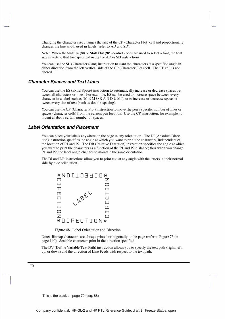
8/12/2019 HPGL2-RTL ReferenceGuide 5961-3526 540pages Sep96
http://slidepdf.com/reader/full/hpgl2-rtl-referenceguide-5961-3526-540pages-sep96 88/539
70
This is the black on page 70 (seq: 88)
Company confidential. HP-GL/2 and HP RTL Reference Guide, draft 2. Freeze Status: open
Changing the character size changes the size of the CP (Character Plot) cell and proportionallychanges the line width used in labels (refer to AD and SD).
Note: When the Shift In () or Shift Out () control codes are used to select a font, the fontsize reverts to that font specified using the AD or SD instructions.
You can use the SL (Character Slant) instruction to slant the characters at a specified angle ineither direction from the left vertical side of the CP (Character Plot) cell. The CP cell is notaltered.
Character Spaces and Text Lines
You can use the ES (Extra Space) instruction to automatically increase or decrease spaces be-tween all characters or lines. For example, ES can be used to increase space between everycharacter in a label such as “M E M O R A N D U M”), or to increase or decrease space be-tween every line of text (such as double-spacing).
You can use the CP (Character Plot) instruction to move the pen a specific number of lines orspaces (character cells) from the current pen location. Use the CP instruction, for example, toindent a label a certain number of spaces.
Label Orientation and Placement
You can place your labels anywhere on the page in any orientation. The DI (Absolute Direc-tion) instruction specifies the angle at which you want to print the characters, independent of the location of P1 and P2. The DR (Relative Direction) instruction specifies the angle at whichyou want to print the characters as a function of the P1 and P2 distance; thus when you changeP1 and P2, the label angle changes to maintain the same orientation.
The DI and DR instructions allow you to print text at any angle with the letters in their normalside-by-side orientation.
Figure 48. Label Orientation and Direction
Note: Bitmap characters are always printed orthogonally to the page (refer to Figure 73 onpage 140). Scalable characters print in the direction specified.
The DV (Define Variable Text Path) instruction allows you to specify the text path (right, left,up, or down) and the direction of Line Feeds with respect to the text path.
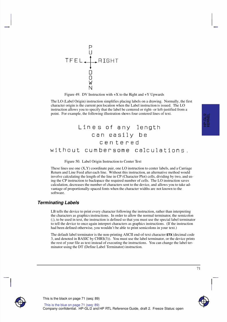
8/12/2019 HPGL2-RTL ReferenceGuide 5961-3526 540pages Sep96
http://slidepdf.com/reader/full/hpgl2-rtl-referenceguide-5961-3526-540pages-sep96 89/539
71
This is the black on page 71 (seq: 89)
Company confidential. HP-GL/2 and HP RTL Reference Guide, draft 2. Freeze Status: open
Figure 49. DV Instruction with +X to the Right and +Y Upwards
The LO (Label Origin) instruction simplifies placing labels on a drawing. Normally, the firstcharacter origin is the current pen location when the Label instruction is issued. The LOinstruction allows you to specify that the label be centered or right- or left-justified from a
point. For example, the following illustration shows four centered lines of text.
Figure 50. Label Origin Instruction to Center Text
These lines use one (X,Y) coordinate pair, one LO instruction to center labels, and a CarriageReturn and Line Feed after each line. Without this instruction, an alternative method wouldinvolve calculating the length of the line in CP (Character Plot) cells, dividing by two, and us-ing the CP instruction to backspace the required number of cells. The LO instruction savescalculation, decreases the number of characters sent to the device, and allows you to take ad-vantage of proportionally-spaced fonts when the character widths are not known to thesoftware.
Terminating Labels
LB tells the device to print every character following the instruction, rather than interpretingthe characters as graphics instructions. In order to allow the normal terminator, the semicolon(;), to be used in text, the instruction is defined so that you must use the special label terminatorto tell the device to once again interpret characters as graphics instructions. (If the instructionhad been defined otherwise, you wouldn’t be able to print semicolons in your text.)
The default label terminator is the non-printing ASCII end-of-text character (decimal code3, and denoted in BASIC by CHR$(3)). You must use the label terminator, or the device printsthe rest of your file as text instead of executing the instructions. You can change the label ter-minator using the DT (Define Label Terminator) instruction.
This is the blue on page 71 (seq: 89)
K E R N E L
H P - G L / 2
8/12/2019 HPGL2-RTL ReferenceGuide 5961-3526 540pages Sep96
http://slidepdf.com/reader/full/hpgl2-rtl-referenceguide-5961-3526-540pages-sep96 90/539
8/12/2019 HPGL2-RTL ReferenceGuide 5961-3526 540pages Sep96
http://slidepdf.com/reader/full/hpgl2-rtl-referenceguide-5961-3526-540pages-sep96 91/539
73
This is the black on page 73 (seq: 91)
Company confidential. HP-GL/2 and HP RTL Reference Guide, draft 2. Freeze Status: open
If you need to use a special character from another set in the middle of a label, using theSS and SA instructions to toggle between sets can be inefficient. Instead, it might be easierto use the control characters shift-in (, decimal code 15) and shift-out (, 14) to toggle
between the sets. For example:SD 1,115,3,3,4,30; Define a standard font
AD 1,5,3,3,4,30; and an alternate font containing the symbol “” (accessed
from the keyboard as “x”)
LB3x–5 ; Create the label, producing:
3 –5
HP-GL/2 Printing
The HP-GL/2 print model specifies how images are constructed and combined when renderinga page in HP-GL/2. The following terms are used:
Primitive—Any graphic item that marks the page (characters, vectors, polygons, and so on).
Destination—A composite of all primitives previously placed on the page.
Source—A solid black primitive possibly with added attributes such as current color and areafill. HP-GL/2 source data does not have transparent bits.
Pattern—An area fill attribute for a graphic object like a polygon, for example, solid fills,hatched fills, shaded fills, and user-defined raster patterns. (User-defined raster patterns can beeither color or monochrome; all other fills are monochrome.)
Current Color—The color of the currently selected pen.
Texture—Monochrome pattern plus current color. See page 366.
Transparency mode—Determines how the pattern’s white pixels affect the destination. Intransparent mode (1), white pixels have no effect on the destination. In opaque mode (2), whitepixels block out corresponding destination areas.
Area Fills
The Line and Fill Attributes group contains instructions for filling primitives: FT (Fill Type)and RF (Raster Fill Definition). The Palette extension contains instructions that determine pencolors (PC) and the number of pens (NP).
The following table shows which graphic images may have color or area fill applied:
Graphic Image Color Area Fill
Vectors Yes NoArcs, circles Yes No
Polygons* Yes Yes
Characters:VectorScalableBitmapped
YesYesYes
YesYesYes
This is the blue on page 73 (seq: 91)
K E R N E L
H P - G L / 2
8/12/2019 HPGL2-RTL ReferenceGuide 5961-3526 540pages Sep96
http://slidepdf.com/reader/full/hpgl2-rtl-referenceguide-5961-3526-540pages-sep96 92/539
74
This is the black on page 74 (seq: 92)
Company confidential. HP-GL/2 and HP RTL Reference Guide, draft 2. Freeze Status: open
* “Polygons” refers to objects filled with the FPinstruction that were created with the polygon,wedge, and rectangle instructions (EA, ER, EW,
PM, RA, RR, and WG).The current color can be applied to any area except user-defined fills having color information(defined by RF and accessed by “FT11”). Area fills cannot be combined; for example, youcannot obtain a “shaded hatch” except by defining a user-defined pattern or screened vectors(using SV).
The Kernel Print Model
In the HP-GL/2 kernel print model, non-white source pixels, to which current color and patternhave been added, replace destination pixels. White pixels imposed on the source by a patternare transparent and have no effect.
Extended Print ModelMore options are allowed when the Technical Graphics and Palette extensions are added to thekernel. Two instructions then determine the state of the HP-GL/2 print model: TR (Transparen-cy Mode) and MC (Merge Control).
MC can perform logical operations (AND, OR, exclusive-OR, and NOT) on non-whitesource, texture, and destination pixels.
TR determines whether white source pixels affect the destination.
The kernel print model is equivalent to “TR1” (transparent), “MC0” (replacement) in the ex-tended print model.
HP-GL/2, HP RTL, and PCL Print Models
Although the HP–GL/2 and the HP RTL and PCL print models are slightly different (notably intheir treatment of whites), logical raster operations (“ROPs”) using TR and MC are similar.Dual-context applications may prefer to remain in HP-GL/2 for efficiency and use the HP-GL/2print model. The complete set of 256 logical operations is listed on page 475.
HP RTL and PCL Print Model HP-GL/2 Print Model
Default PrintModel
The non-white source and pattern pixelsare OR’d with each other and replacedestination pixels.
The non-white source and pattern pixelsare OR’d with each other and replacedestination pixels.
TransparencyModes
HP RTL and PCL have both source andpattern transparency modes, which de-
termine whether white source and pat-tern pixels are applied to the destina-tion.
“White” is defined by the white refer-ence in the color space.
Default transparency: white source andpattern pixels are transparent.
HP-GL/2 has pattern transparencymode, but not source transparency
mode, since there is no bounding box asin raster mode or character cells.
The CR instruction defines “white” bysetting a white reference.
Default transparency: white pattern pix-els are transparent.

8/12/2019 HPGL2-RTL ReferenceGuide 5961-3526 540pages Sep96
http://slidepdf.com/reader/full/hpgl2-rtl-referenceguide-5961-3526-540pages-sep96 93/539
75
This is the black on page 75 (seq: 93)
Company confidential. HP-GL/2 and HP RTL Reference Guide, draft 2. Freeze Status: open
HP-GL/2 Print ModelHP RTL and PCL Print Model
Current Color The current color is selected from the
palette by the Foreground Color(*v#S) command.The default is black.
HP RTL and PCL cannot import HP-GL/2 patterns.
The current color is selected from the
palette by the SP instruction.The default is pen number 0 (normallywhite).
HP-GL/2 can import HP RTL and PCLpatterns.
Area Fill Area fill is selected by pre-defined(*c#G) and downloadable(*c#W) patterns.
Area fill is selected by pre-defined (FT)and downloadable (RF) patterns.
LogicalOperations
*l#O determines the interaction be-tween source, texture, and destination.
“MC1” determines the interaction be-tween source, texture, and destination.
K E R N E L
H P - G L / 2
This is the blue on page 75 (seq: 93)

8/12/2019 HPGL2-RTL ReferenceGuide 5961-3526 540pages Sep96
http://slidepdf.com/reader/full/hpgl2-rtl-referenceguide-5961-3526-540pages-sep96 94/539
76
This is the black on page 76 (seq: 94)
Company confidential. HP-GL/2 and HP RTL Reference Guide, draft 2. Freeze Status: open
8/12/2019 HPGL2-RTL ReferenceGuide 5961-3526 540pages Sep96
http://slidepdf.com/reader/full/hpgl2-rtl-referenceguide-5961-3526-540pages-sep96 95/539
77
This is the black on page 77 (seq: 95)
Company confidential. HP-GL/2 and HP RTL Reference Guide, draft 2. Freeze Status: open
Chapter 4: The HP-GL/2 Extensions
This chapter describes the Extension instructions that rely on specific technologies or function-ality. The Extensions are:
The Technical Graphics Extension page 77.
The Palette Extension page 82.
The Dual-Context Extension page 83.
The Digitizing Extension page 89.
The Advanced Drawing Extension page 92.
The Advanced Text Extension page 94.
The Technical Graphics Extension
Many HP-GL/2 devices, in particular pen plotters, support the Technical Graphics Extension,though most of these instructions are not available on PCL devices. These instructions giveadded flexibility when your applications require more technical functions, such as computer-aided design and drawing, architectural rendering, integrated circuit layout, and so on. Theinstructions in the Technical Graphics Extension let you achieve the following results:
Specify chord tolerances for arcs, circles, and wedges.Design and download user-defined characters.
Turn on and off the device’s automatic cutter.
Advance the media for long-axis plotting.
Write a message to the device’s control panel.
Ask the device to output information to the computer.
Specify a user-defined page size.
Set the quality level of output.
Sort your plot data for faster throughput on pen plotters.
Set the pen speed on pen plotters.These instructions form the Technical Graphics Extension (those marked * are device-specific):
Á Á Á Á Á Á Á Á Á Á
Á Á Á Á Á Á Á Á Á Á
BP Begin PlotÁ Á Á Á Á Á Á Á Á Á Á Á Á Á Á Á Á Á
Á Á Á Á Á Á Á Á Á Á Á Á Á Á Á Á Á Á
Indicates the beginning of a plot.Á Á Á Á Á Á Á Á Á Á
Á Á Á Á Á Á Á Á Á Á
Á Á Á Á Á Á Á Á Á Á
CT Chord Tolerance ModeÁ Á Á Á Á Á Á Á Á Á Á Á Á Á Á Á Á Á
Á Á Á Á Á Á Á Á Á Á Á Á Á Á Á Á Á Á
Á Á Á Á Á Á Á Á Á Á Á Á Á Á Á Á Á Á
Allows you to adjust the number of chords in an arc or circleby indicating how chords are to be specified.
Á Á Á Á Á Á Á Á Á Á
Á Á Á Á Á Á Á Á Á Á
DL Download Character Á Á Á Á Á Á Á Á Á Á Á Á Á Á Á Á Á Á
Á Á Á Á Á Á Á Á Á Á Á Á Á Á Á Á Á Á
Allows you to store user-defined characters a buffer.*
Á Á Á Á Á Á Á Á Á Á
Á Á Á Á Á Á Á Á Á Á
EC Enable Cutter Á Á Á Á Á Á Á Á Á Á Á Á Á Á Á Á Á Á
Á Á Á Á Á Á Á Á Á Á Á Á Á Á Á Á Á Á
Turns a device’s automatic cutter on or off.*
Á Á Á Á Á Á Á Á Á Á
Á Á Á Á Á Á Á Á Á Á
FR Frame AdvanceÁ Á Á Á Á Á Á Á Á Á Á Á Á Á Á Á Á Á
Á Á Á Á Á Á Á Á Á Á Á Á Á Á Á Á Á Á
Advances the media to the next frame for long-axis plotting.
This is the blue on page 77 (seq: 95)
E X T E N S I O N S
H P - G L / 2
This is the blue on page 77 (seq: 95)
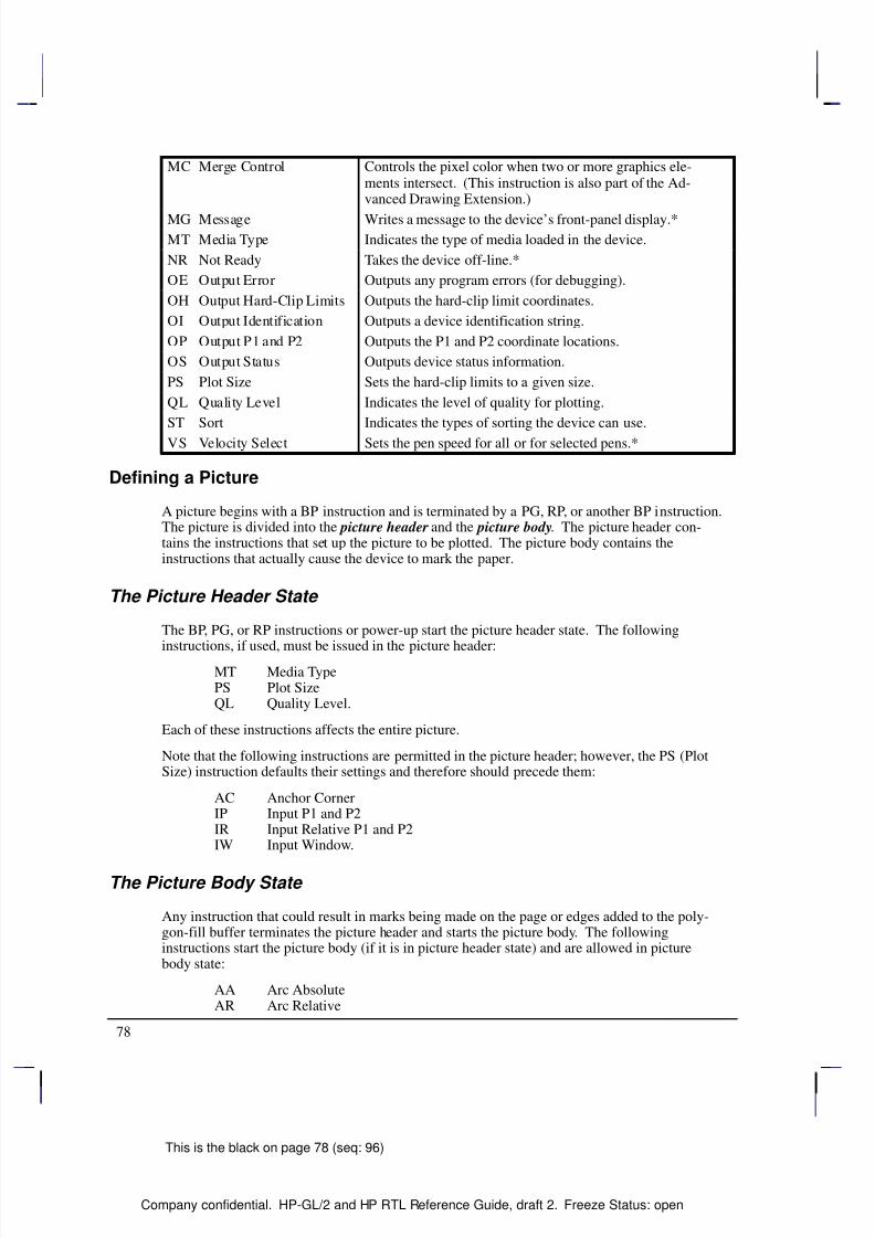
8/12/2019 HPGL2-RTL ReferenceGuide 5961-3526 540pages Sep96
http://slidepdf.com/reader/full/hpgl2-rtl-referenceguide-5961-3526-540pages-sep96 96/539
78
This is the black on page 78 (seq: 96)
Company confidential. HP-GL/2 and HP RTL Reference Guide, draft 2. Freeze Status: open
Á Á Á Á Á Á Á Á Á
Á Á Á Á Á Á Á Á Á
Á Á Á Á Á Á Á Á Á
Á Á Á Á Á Á Á Á Á
MC Merge ControlÁ Á Á Á Á Á Á Á Á Á Á Á Á Á Á Á Á Á
Á
Á Á Á Á Á Á Á Á Á Á Á Á Á Á Á Á Á
Á Á Á Á Á Á Á Á Á Á Á Á Á Á Á Á Á Á
Á Á Á Á Á Á Á Á Á Á Á Á Á Á Á Á Á Á
Controls the pixel color when two or more graphics ele-ments intersect. (This instruction is also part of the Ad-vanced Drawing Extension.)
Á Á Á Á Á Á Á Á Á
Á Á Á Á Á Á Á Á Á
MG Message Á Á Á Á Á Á Á Á Á Á Á Á Á Á Á Á Á Á
Á Á Á Á Á Á Á Á Á Á Á Á Á Á Á Á Á Á
Writes a message to the device’s front-panel display.*
Á Á Á Á Á Á Á Á Á
Á Á Á Á Á Á Á Á Á
MT Media TypeÁ Á Á Á Á Á Á Á Á Á Á Á Á Á Á Á Á Á
Á Á Á Á Á Á Á Á Á Á Á Á Á Á Á Á Á Á
Indicates the type of media loaded in the device.
Á Á Á Á Á Á Á Á Á
Á Á Á Á Á Á Á Á Á
NR Not ReadyÁ Á Á Á Á Á Á Á Á Á Á Á Á Á Á Á Á Á
Á Á Á Á Á Á Á Á Á Á Á Á Á Á Á Á Á Á
Takes the device off-line.*
Á Á Á Á Á Á Á Á Á
Á Á Á Á Á Á Á Á Á
OE Output ErrorÁ Á Á Á Á Á Á Á Á Á Á Á Á Á Á Á Á Á
Á Á Á Á Á Á Á Á Á Á Á Á Á Á Á Á Á Á
Outputs any program errors (for debugging).Á Á Á Á Á Á Á Á Á
Á Á Á Á Á Á Á Á Á
OH Output Hard-Clip LimitsÁ Á Á Á Á Á Á Á Á Á Á Á Á Á Á Á Á Á
Á Á Á Á Á Á Á Á Á Á Á Á Á Á Á Á Á Á
Outputs the hard-clip limit coordinates.Á Á Á Á Á Á Á Á Á
Á Á Á Á Á Á Á Á Á
OI Output IdentificationÁ Á Á Á Á Á Á Á Á Á Á Á Á Á Á Á Á Á
Á Á Á Á Á Á Á Á Á Á Á Á Á Á Á Á Á Á
Outputs a device identification string.Á Á Á Á Á Á Á Á Á
Á Á Á Á Á Á Á Á Á
OP Output P1 and P2Á Á Á Á Á Á Á Á Á Á Á Á Á Á Á Á Á Á
Á Á Á Á Á Á Á Á Á Á Á Á Á Á Á Á Á Á
Outputs the P1 and P2 coordinate locations.Á Á Á Á Á Á Á Á Á
Á Á Á Á Á Á Á Á Á
OS Output StatusÁ Á Á Á Á Á Á Á Á Á Á Á Á Á Á Á Á Á
Á Á Á Á Á Á Á Á Á Á Á Á Á Á Á Á Á Á
Outputs device status information.Á Á Á Á Á Á Á Á Á
Á Á Á Á Á Á Á Á Á
PS Plot Size Á Á Á Á Á Á Á Á Á Á Á Á Á Á Á Á Á Á
Á Á Á Á Á Á Á Á Á Á Á Á Á Á Á Á Á Á
Sets the hard-clip limits to a given size.
Á Á Á Á Á Á Á Á Á
Á Á Á Á Á Á Á Á Á
QL Quality Level Á Á Á Á Á Á Á Á Á Á Á Á Á Á Á Á Á Á
Á Á Á Á Á Á Á Á Á Á Á Á Á Á Á Á Á Á
Indicates the level of quality for plotting.
Á Á Á Á Á Á Á Á Á
Á Á Á Á Á Á Á Á Á
ST Sort Á Á Á Á Á Á Á Á Á Á Á Á Á Á Á Á Á Á
Á Á Á Á Á Á Á Á Á Á Á Á Á Á Á Á Á Á
Indicates the types of sorting the device can use.
Á Á Á Á Á Á Á Á Á
Á Á Á Á Á Á Á Á Á
VS Velocity SelectÁ Á Á Á Á Á Á Á Á Á Á Á Á Á Á Á Á Á
Á Á Á Á Á Á Á Á Á Á Á Á Á Á Á Á Á Á
Sets the pen speed for all or for selected pens.*
Defining a Picture
A picture begins with a BP instruction and is terminated by a PG, RP, or another BP instruction.The picture is divided into the picture header and the picture body. The picture header con-tains the instructions that set up the picture to be plotted. The picture body contains theinstructions that actually cause the device to mark the paper.
The Picture Header State
The BP, PG, or RP instructions or power-up start the picture header state. The following
instructions, if used, must be issued in the picture header:MT Media TypePS Plot SizeQL Quality Level.
Each of these instructions affects the entire picture.
Note that the following instructions are permitted in the picture header; however, the PS (PlotSize) instruction defaults their settings and therefore should precede them:
AC Anchor CornerIP Input P1 and P2IR Input Relative P1 and P2IW Input Window.
The Picture Body State
Any instruction that could result in marks being made on the page or edges added to the poly-gon-fill buffer terminates the picture header and starts the picture body. The followinginstructions start the picture body (if it is in picture header state) and are allowed in picturebody state:
AA Arc AbsoluteAR Arc Relative
8/12/2019 HPGL2-RTL ReferenceGuide 5961-3526 540pages Sep96
http://slidepdf.com/reader/full/hpgl2-rtl-referenceguide-5961-3526-540pages-sep96 97/539
79
This is the black on page 79 (seq: 97)
Company confidential. HP-GL/2 and HP RTL Reference Guide, draft 2. Freeze Status: open
AT Absolute Arc Three PointBR Bezier RelativeBZ Bezier Absolute
CI CircleCP Character PlotEA Edge Rectangle AbsoluteEP Edge PolygonER Edge Rectangle RelativeEW Edge WedgeFP Fill PolygonLB LabelPA Plot AbsolutePD Pen DownPE Polyline EncodedPM Polygon ModePR Plot RelativePU Pen Up (with parameters)
RA Fill Rectangle AbsoluteRR Fill Rectangle RelativeRT Relative Arc Three PointWG Fill Wedge.
Replotting and the Picture Header
RP (Replot) should be placed immediately following the picture, with no intervening instruc-tions other than output requests. The currently stored plot referenced by RP will disappearupon the next BP instruction, and also upon the next transition into the picture body. If a pic-ture does not start with a BP (that is, it began after the last PG or RP), and an RP is issued whilestill in the picture header, it is device-dependent whether the previous picture is replotted.
Chords and Chord Tolerance
To draw curves, the device draws a series of straight lines, called chords , for each arc segment.The smoothness of the curve depends on the number of chords used to draw it—the morechords, the smoother the shape appears. Figure 65 on page 125 shows circles drawn with dif-ferent numbers of chords.
The number of chords in any curved shape is determined by the chord tolerance—the allow-able deviation from a smooth curve. Many instructions let you set the chord tolerance youwant. Chord tolerance can be specified as either an angle in degrees, or as the maximum dis-tance the arc drawn may deviate from the true arc. These two methods are called chord angleand deviation distance. The chord angle is the default method. The Chord Tolerance Mode(CT) instruction selects the method.
Note: Do not use an “adaptive” line type (see the description of the LT instruction on page215) when you draw circles, arcs, wedges, or polygons. The device will attempt to draw thecomplete pattern in every chord; there are 72 chords in a circle using the default chord angle.
The Downloadable Set and User-Defined Characters
If you need special label characters or symbols that are not included in any of the suppliedcharacter sets, you can design your own characters or symbols, or even an entire character set.The DL (Download Character) instruction allows you to download these characters. The DL
This is the blue on page 79 (seq: 97)
E X T E N S I O N S
H P - G L / 2
8/12/2019 HPGL2-RTL ReferenceGuide 5961-3526 540pages Sep96
http://slidepdf.com/reader/full/hpgl2-rtl-referenceguide-5961-3526-540pages-sep96 98/539
80
This is the black on page 80 (seq: 98)
Company confidential. HP-GL/2 and HP RTL Reference Guide, draft 2. Freeze Status: open
instruction can define up to 94 characters to be stored in a buffer for repeated use during a plot.The character plot cell used by the DL instruction is always a fixed-space character cell, re-gardless of the spacing in the current font.
Merging Pixels
The MC (Merge Control) instruction controls the color of pixels where two or more page mark-ing primitives intersect on the page. This instruction, like the Logical Operation (*l#O)command of HP RTL, supports all 256 Microsoft Windows ternary (ROP3) raster operationcodes—see page 475. Raster operations specify how source, destination, and pattern data arecombined to produce final images. A common application of the MC instruction is the render-ing of complex polygon fill patterns. You can find a more detailed explanation of how rasteroperations work in Chapter 10: Interactions between Picture Elements on page 365.
Obtaining Device Output
When the device receives an output instruction, it responds by making the information avail-able in the form of an output response that can be read by a computer with an input statement.Most programming languages use an input statement such as ENTER, INPUT, READ, READLN,FSCANF, or GET to read the response from the device. When you read the output response, besure to specify the correct number and type of variables that are to receive the data. For exam-ple, BASIC requires that a character string variable should be in the form A$, and a numericvariable can be in the form A. Refer to your programming language documentation for the cor-rect input statement to use and the correct format for numeric and character-string variables.Output responses containing more than one piece of information should be read completely toclear the output buffer, with a separate variable for each piece of information. For example, theOH (Output Hard-Clip Limits) instruction outputs four integers; an input statement might be:
fscanf (device, ”%d,%d,%d,%d\n”, &x1, &y1, &x2, &y2);
or:
INPUT #1, A,B,Y,Z
Note that the output instructions must be terminated with a semicolon.
Output instructions should not be used on networks or unidirectional interfaces.
For Centronics Users
The Centronics interface supports data transmission in one direction only. They do not returninformation to the computer. However, output instructions will perform other expected opera-tions, such as setting or clearing status bits in the device’s memory.
For HP-IB Users A device signals the end of its output response with an output response terminator. For HP-IBusers, the default output response terminator is a carriage return followed by a line feed ().
Be sure that your device is not set to LISTEN ONLY. If it is, the device will not send an outputresponse and your program will halt. Refer to your product documentation for more informa-tion about HP-IB addressing.
8/12/2019 HPGL2-RTL ReferenceGuide 5961-3526 540pages Sep96
http://slidepdf.com/reader/full/hpgl2-rtl-referenceguide-5961-3526-540pages-sep96 99/539
81
This is the black on page 81 (seq: 99)
Company confidential. HP-GL/2 and HP RTL Reference Guide, draft 2. Freeze Status: open
For RS-232-C, Bi-Tronics, and MIO Users
The device outputs information according to the handshake protocol. Your computer documen-
tation should specify whether or not delays are required.
A device signals the end of its output response with an output response terminator. For theRS-232-C, Bi-Tronics, and MIO interfaces, the default output response terminator is a carriagereturn ().
Using Output Instructions
Use the following procedures for sending output instructions to your device:
1. Send the output instruction to the device as you do other HP-GL/2 instructions. Note thatall the output instructions use terminators, normally a semicolon, and have no parameters.
2. Read the device’s output response immediately, using an input statement appropriate to
your computer language, keeping in mind the number and type of variables.Do not send multiple output instructions and then try to read all the responses sequentially.This can lead to intermittent timing problems, depending on what the computer and the deviceare currently doing.
Identifying the Device and its Functions
When you have more than one peripheral (for example, several plotters and printers) connectedto a computer, it may be necessary to have the device output its identification so that you canbe sure it is on-line. The OI (Output Identification) instruction can output the device ID to thecomputer.
Obtaining Error Information Use the OE (Output Error) instruction for error retrieval. The OE instruction outputs the errornumber that corresponds to the first HP-GL/2 error the device receives. Use this instruction toidentify errors by number when debugging a program. In addition, these errors set the error bitof the status byte in the response to OS (Output Status) instruction.
Obtaining Status Byte Information
The eight-bit status byte stores information about device operating conditions. Use the OS(Output Status) instruction to learn the status of the device’s current operating conditions. Eachcondition is assigned a bit number (from 0 to 7) and a corresponding decimal value. (Theconditions, bit numbers, and corresponding decimal values are shown in the description of theOS instruction.) You can obtain the value of the status byte by reading the response to the OSinstruction or executing an HP-IB serial poll of the device.
Summary of Output Responses
The following table lists output responses generated by HP-GL/2 output instructions. Note thatnumeric ranges do not include the sign of the response. For example, if a five-digit response isa negative value, a minus sign precedes the five digits. The minus sign does not replace a digit.In addition to these parameters, the output terminator is always sent at the end of output, andcommas are sent to separate parameters.
This is the blue on page 81 (seq: 99)
E X T E N S I O N S
H P - G L / 2
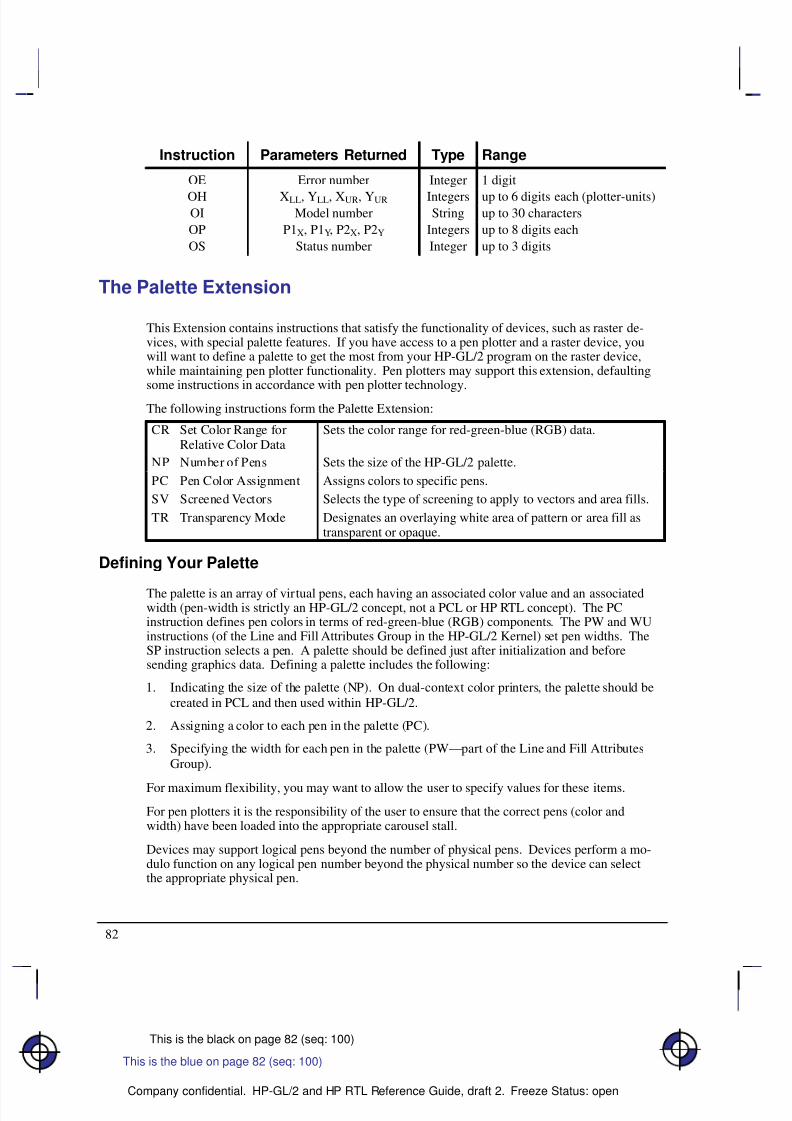
8/12/2019 HPGL2-RTL ReferenceGuide 5961-3526 540pages Sep96
http://slidepdf.com/reader/full/hpgl2-rtl-referenceguide-5961-3526-540pages-sep96 100/539
8/12/2019 HPGL2-RTL ReferenceGuide 5961-3526 540pages Sep96
http://slidepdf.com/reader/full/hpgl2-rtl-referenceguide-5961-3526-540pages-sep96 101/539
8/12/2019 HPGL2-RTL ReferenceGuide 5961-3526 540pages Sep96
http://slidepdf.com/reader/full/hpgl2-rtl-referenceguide-5961-3526-540pages-sep96 102/539
8/12/2019 HPGL2-RTL ReferenceGuide 5961-3526 540pages Sep96
http://slidepdf.com/reader/full/hpgl2-rtl-referenceguide-5961-3526-540pages-sep96 103/539
8/12/2019 HPGL2-RTL ReferenceGuide 5961-3526 540pages Sep96
http://slidepdf.com/reader/full/hpgl2-rtl-referenceguide-5961-3526-540pages-sep96 104/539
8/12/2019 HPGL2-RTL ReferenceGuide 5961-3526 540pages Sep96
http://slidepdf.com/reader/full/hpgl2-rtl-referenceguide-5961-3526-540pages-sep96 105/539
87
This is the black on page 87 (seq: 105)
Company confidential. HP-GL/2 and HP RTL Reference Guide, draft 2. Freeze Status: open
Modifications to HP-GL/2 Instructions in Dual-Context Mode
The following HP-GL/2 instructions are modified in Dual-Context Mode as summarized below.
Functional differences are also described in the individual instruction descriptions. Thosemarked with an asterisk (*) are for PCL only.
Á Á Á Á Á Á Á Á
Á
Á Á Á Á Á Á Á
Á Á Á Á Á Á Á Á
AC,Anchor Corner (*)
Á Á Á Á Á Á Á Á Á Á Á Á Á Á Á Á Á Á Á Á
Á
Á Á Á Á Á Á Á Á Á Á Á Á Á Á Á Á Á Á Á
Á Á Á Á Á Á Á Á Á Á Á Á Á Á Á Á Á Á Á Á
IN, DF, or E place the anchor point at the lower-left corner of thepicture frame relative to the current coordinate system.
Á Á Á Á Á Á Á Á
Á
Á Á Á Á Á Á Á
Á Á Á Á Á Á Á Á
Á
Á Á Á Á Á Á Á
Á Á Á Á Á Á Á Á
BP,Begin Plot (*)(Technical Extension)
Á Á Á Á Á Á Á Á Á Á Á Á Á Á Á Á Á Á Á Á
Á
Á Á Á Á Á Á Á Á Á Á Á Á Á Á Á Á Á Á Á
Á Á Á Á Á Á Á Á Á Á Á Á Á Á Á Á Á Á Á Á
Á
Á Á Á Á Á Á Á Á Á Á Á Á Á Á Á Á Á Á Á
Á Á Á Á Á Á Á Á Á Á Á Á Á Á Á Á Á Á Á Á
In PCL devices, the PG portion of BP is ignored and BP is mappedto IN regardless of the kind and value parameters. Data previouslyformatted for the current page is not cleared.
(In HP RTL devices, BP performs the PG and IN functions.)Á Á Á Á Á Á Á Á
Á
Á Á Á Á Á Á Á
Á
Á Á Á Á Á Á Á
Á Á Á Á Á Á Á Á
DF,Default Values (*)
Á Á Á Á Á Á Á Á Á Á Á Á Á Á Á Á Á Á Á Á
Á
Á Á Á Á Á Á Á Á Á Á Á Á Á Á Á Á Á Á Á
Á
Á Á Á Á Á Á Á Á Á Á Á Á Á Á Á Á Á Á Á
Á Á Á Á Á Á Á Á Á Á Á Á Á Á Á Á Á Á Á Á
“AC;” places the anchor point at the lower-left corner of the pictureframe relative to the current coordinate system.
“IW;” sets the user window equal to PCL picture frame window.Á Á Á Á Á Á Á Á
Á
Á Á Á Á Á Á Á
Á Á Á Á Á Á Á Á
Á
Á Á Á Á Á Á Á
Á Á Á Á Á Á Á Á
Á
Á Á Á Á Á Á Á
Á
Á Á Á Á Á Á Á
Á Á Á Á Á Á Á Á
Á Á Á Á Á Á Á Á
FT,Fill Type
Á Á Á Á Á Á Á Á Á Á Á Á Á Á Á Á Á Á Á Á
Á
Á Á Á Á Á Á Á Á Á Á Á Á Á Á Á Á Á Á Á
Á Á Á Á Á Á Á Á Á Á Á Á Á Á Á Á Á Á Á Á
Á
Á Á Á Á Á Á Á Á Á Á Á Á Á Á Á Á Á Á Á
Á Á Á Á Á Á Á Á Á Á Á Á Á Á Á Á Á Á Á Á
Á
Á Á Á Á Á Á Á Á Á Á Á Á Á Á Á Á Á Á Á
Á
Á Á Á Á Á Á Á Á Á Á Á Á Á Á Á Á Á Á Á
Á Á Á Á Á Á Á Á Á Á Á Á Á Á Á Á Á Á Á Á
Á Á Á Á Á Á Á Á Á Á Á Á Á Á Á Á Á Á Á Á
Additional fill types (21 and 22) are imported from PCL or HP RTL.
Fill type 21 selects a PCL or HP RTL predefined patterned fill. Op-tion 1 specifies a pattern type from 1 to 6 (see the FT instruction de-scription). Option 2 is ignored.
Fill type 22 uses the PCL or HP RTL user-defined fill specified by
*c#W. Option 1 is the PCL or HP RTL ID of the user-definedfill. Option 2 is ignored. An invalid option 1 (for example, the pat-tern has been deleted), prints a solid fill in the current color.
Á Á Á Á Á Á Á Á
Á
Á Á Á Á Á Á Á
Á
Á Á Á Á Á Á Á
Á Á Á Á Á Á Á Á
IP,Input P1 and P2 (*)
Á Á Á Á Á Á Á Á Á Á Á Á Á Á Á Á Á Á Á Á
Á
Á Á Á Á Á Á Á Á Á Á Á Á Á Á Á Á Á Á Á
Á
Á Á Á Á Á Á Á Á Á Á Á Á Á Á Á Á Á Á Á
Á Á Á Á Á Á Á Á Á Á Á Á Á Á Á Á Á Á Á Á
“IP;” sets P1 to the lower-left corner of the PCL picture frame(viewed from the current HP-GL/2 orientation) and P2 to the oppo-site corner. Parameters are scaled by the picture frame scaling fac-tor.
Á Á Á Á Á Á Á Á
Á
Á Á Á Á Á Á Á
Á Á Á Á Á Á Á Á
Á
Á Á Á Á Á Á Á
Á Á Á Á Á Á Á Á
IR,Input RelativeP1 and P2 (*)
Á Á Á Á Á Á Á Á Á Á Á Á Á Á Á Á Á Á Á Á
Á
Á Á Á Á Á Á Á Á Á Á Á Á Á Á Á Á Á Á Á
Á Á Á Á Á Á Á Á Á Á Á Á Á Á Á Á Á Á Á Á
Á
Á Á Á Á Á Á Á Á Á Á Á Á Á Á Á Á Á Á Á
Á Á Á Á Á Á Á Á Á Á Á Á Á Á Á Á Á Á Á Á
The references to the hard-clip limits are replaced by the PCL pic-ture frame. The default positions for P1 and P2 are the lower-leftand upper-right corners of the picture frame, as viewed from the cur-rent orientation.
Á Á Á Á Á Á Á Á
Á
Á Á Á Á Á Á Á
Á Á Á Á Á Á Á Á
Á
Á Á Á Á Á Á Á
Á Á Á Á Á Á Á Á
IW,Input Window (*)
Á Á Á Á Á Á Á Á Á Á Á Á Á Á Á Á Á Á Á Á
Á
Á Á Á Á Á Á Á Á Á Á Á Á Á Á Á Á Á Á Á
Á Á Á Á Á Á Á Á Á Á Á Á Á Á Á Á Á Á Á Á
Á
Á Á Á Á Á Á Á Á Á Á Á Á Á Á Á Á Á Á Á
Á Á Á Á Á Á Á Á Á Á Á Á Á Á Á Á Á Á Á Á
“IW;” defaults the window to the PCL picture frame. The maximumprintable area is the intersection of the user-defined window, the PCLpicture frame, the PCL logical page, and the hard-clip limits. Pa-rameters specified in plotter-units are scaled by the picture framescaling factor.
E X T E N S I O N S
H P - G L / 2
This is the blue on page 87 (seq: 105)
8/12/2019 HPGL2-RTL ReferenceGuide 5961-3526 540pages Sep96
http://slidepdf.com/reader/full/hpgl2-rtl-referenceguide-5961-3526-540pages-sep96 106/539
8/12/2019 HPGL2-RTL ReferenceGuide 5961-3526 540pages Sep96
http://slidepdf.com/reader/full/hpgl2-rtl-referenceguide-5961-3526-540pages-sep96 107/539
8/12/2019 HPGL2-RTL ReferenceGuide 5961-3526 540pages Sep96
http://slidepdf.com/reader/full/hpgl2-rtl-referenceguide-5961-3526-540pages-sep96 108/539
8/12/2019 HPGL2-RTL ReferenceGuide 5961-3526 540pages Sep96
http://slidepdf.com/reader/full/hpgl2-rtl-referenceguide-5961-3526-540pages-sep96 109/539
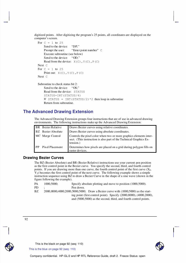
8/12/2019 HPGL2-RTL ReferenceGuide 5961-3526 540pages Sep96
http://slidepdf.com/reader/full/hpgl2-rtl-referenceguide-5961-3526-540pages-sep96 110/539
92
This is the black on page 92 (seq: 110)
Company confidential. HP-GL/2 and HP RTL Reference Guide, draft 2. Freeze Status: open
digitized points. After digitizing the program’s 25 points, all coordinates are displayed on thecomputer’s screen.
For C = 1 to 25
Send to the device: “DP;”Prompt the user: “Enter point number” C
Execute subroutine (see below)
Send to the device: “OD;”
Read from the device: X(C),Y(C),P(C)
Next C
For C = 1 to 25
Print out: X(C),Y(C),P(C)
Next C
Subroutine to check status bit 2:
Send to the device: “OS;”
Read from the device: STATUSSTATUS=INT(STATUS/4)
If STATUS = INT(STATUS/2)*2 then loop in subroutine
Return from subroutine.
The Advanced Drawing Extension
The Advanced Drawing Extension groups four instructions that are of use in advanced drawingenvironments. The following instructions make up the Advanced Drawing Extension:
Á Á Á Á Á Á Á Á
Á Á Á Á Á Á Á Á
BR Bezier RelativeÁ Á Á Á Á Á Á Á Á Á Á Á Á Á Á Á Á Á Á
Á Á Á Á Á Á Á Á Á Á Á Á Á Á Á Á Á Á Á
Draws Bezier curves using relative coordinates.
Á Á Á Á Á Á Á Á
Á Á Á Á Á Á Á Á
BZ Bezier AbsoluteÁ Á Á Á Á Á Á Á Á Á Á Á Á Á Á Á Á Á Á
Á Á Á Á Á Á Á Á Á Á Á Á Á Á Á Á Á Á Á
Draws Bezier curves using absolute coordinates.
Á Á Á Á Á Á Á Á
Á Á Á Á Á Á Á Á
Á Á Á Á Á Á Á Á
MC Merge ControlÁ Á Á Á Á Á Á Á Á Á Á Á Á Á Á Á Á Á Á
Á
Á Á Á Á Á Á Á Á Á Á Á Á Á Á Á Á Á Á
Á Á Á Á Á Á Á Á Á Á Á Á Á Á Á Á Á Á Á
Controls the pixel color when two or more graphics elements inter-sect. (This instruction is also part of the Technical Graphics Ex-tension.)
Á Á Á Á Á Á Á Á
Á Á Á Á Á Á Á Á
Á Á Á Á Á Á Á Á
PP Pixel Placement Á Á Á Á Á Á Á Á Á Á Á Á Á Á Á Á Á Á Á
Á
Á Á Á Á Á Á Á Á Á Á Á Á Á Á Á Á Á Á
Á Á Á Á Á Á Á Á Á Á Á Á Á Á Á Á Á Á Á
Determines how pixels are placed on a grid during polygon fills onraster devices.
Drawing Bezier Curves
The BZ (Bezier Absolute) and BR (Bezier Relative) instructions use your current pen positionas the first control point in the Bezier curve. You specify the second, third, and fourth controlpoints. If you are drawing more than one curve, the fourth control point of the first curve (X3,Y3) becomes the first control point of the next curve. The following example shows a simpleinstruction sequence using BZ to draw a Bezier Curve in the shape of a sine wave (shown in thefigure following the example).
PA 1000,5000; Specify absolute plotting and move to position (1000,5000).PD ; Pen down.
BZ 2000,8000,4000,2000,5000,5000; Draw a Bezier curve with (1000,5000) as the start-
ing point (first control point). Specify (2000,8000), (4000,2000),
and (5000,5000) as the second, third, and fourth control points.
This is the blue on page 92 (seq: 110)
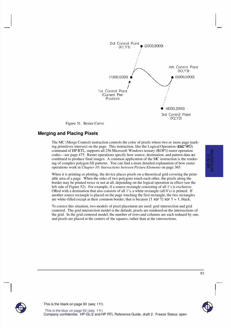
8/12/2019 HPGL2-RTL ReferenceGuide 5961-3526 540pages Sep96
http://slidepdf.com/reader/full/hpgl2-rtl-referenceguide-5961-3526-540pages-sep96 111/539
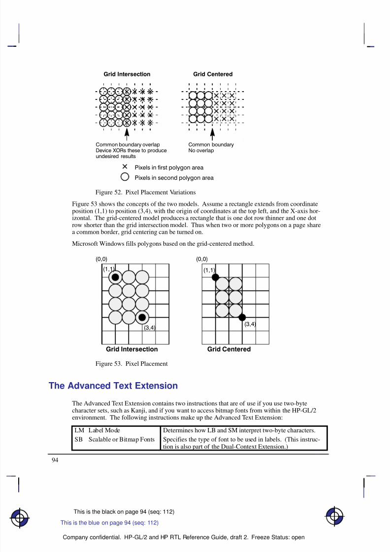
8/12/2019 HPGL2-RTL ReferenceGuide 5961-3526 540pages Sep96
http://slidepdf.com/reader/full/hpgl2-rtl-referenceguide-5961-3526-540pages-sep96 112/539
94
This is the black on page 94 (seq: 112)
Company confidential. HP-GL/2 and HP RTL Reference Guide, draft 2. Freeze Status: open
Figure 52. Pixel Placement Variations
Figure 53 shows the concepts of the two models. Assume a rectangle extends from coordinateposition (1,1) to position (3,4), with the origin of coordinates at the top left, and the X-axis hor-izontal. The grid-centered model produces a rectangle that is one dot row thinner and one dotrow shorter than the grid intersection model. Thus when two or more polygons on a page sharea common border, grid centering can be turned on.
Microsoft Windows fills polygons based on the grid-centered method.
Figure 53. Pixel Placement
The Advanced Text Extension
The Advanced Text Extension contains two instructions that are of use if you use two-bytecharacter sets, such as Kanji, and if you want to access bitmap fonts from within the HP-GL/2environment. The following instructions make up the Advanced Text Extension:
Á Á Á Á Á Á Á Á Á
Á Á Á Á Á Á Á Á Á
LM Label Mode Á Á Á Á Á Á Á Á Á Á Á Á Á Á Á Á Á Á
Á Á Á Á Á Á Á Á Á Á Á Á Á Á Á Á Á Á
Determines how LB and SM interpret two-byte characters.
Á Á Á Á Á Á Á Á Á
Á Á Á Á Á Á Á Á Á
Á Á Á Á Á Á Á Á Á
SB Scalable or Bitmap FontsÁ Á Á Á Á Á Á Á Á Á Á Á Á Á Á Á Á Á
Á
Á Á Á Á Á Á Á Á Á Á Á Á Á Á Á Á Á
Á Á Á Á Á Á Á Á Á Á Á Á Á Á Á Á Á Á
Specifies the type of font to be used in labels. (This instruc-tion is also part of the Dual-Context Extension.)
This is the blue on page 94 (seq: 112)
8/12/2019 HPGL2-RTL ReferenceGuide 5961-3526 540pages Sep96
http://slidepdf.com/reader/full/hpgl2-rtl-referenceguide-5961-3526-540pages-sep96 113/539
8/12/2019 HPGL2-RTL ReferenceGuide 5961-3526 540pages Sep96
http://slidepdf.com/reader/full/hpgl2-rtl-referenceguide-5961-3526-540pages-sep96 114/539
8/12/2019 HPGL2-RTL ReferenceGuide 5961-3526 540pages Sep96
http://slidepdf.com/reader/full/hpgl2-rtl-referenceguide-5961-3526-540pages-sep96 115/539
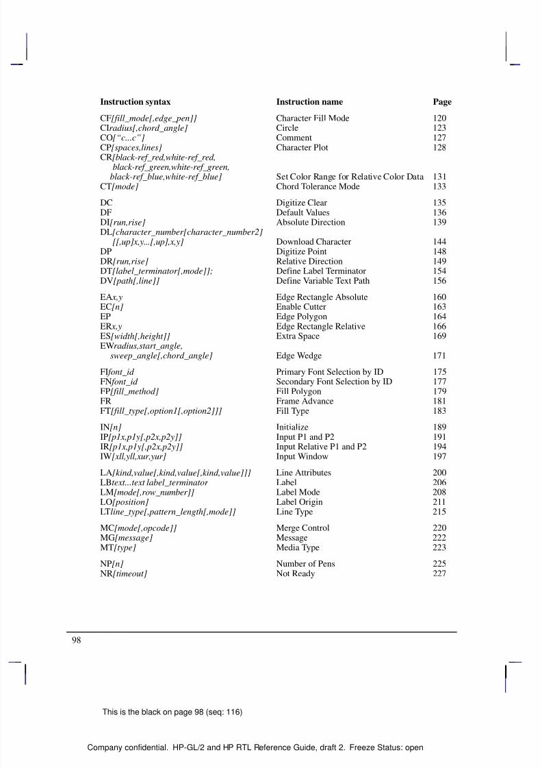
8/12/2019 HPGL2-RTL ReferenceGuide 5961-3526 540pages Sep96
http://slidepdf.com/reader/full/hpgl2-rtl-referenceguide-5961-3526-540pages-sep96 116/539
98
This is the black on page 98 (seq: 116)
Company confidential. HP-GL/2 and HP RTL Reference Guide, draft 2. Freeze Status: open
Instruction syntax Instruction name Page
CF[fill_mode[,edge_pen]] Character Fill Mode 120CIradius[,chord_angle] Circle 123CO[“c...c”] Comment 127CP[spaces,lines] Character Plot 128CR[black-ref_red,white-ref_red, black-ref_green,white-ref_green, black-ref_blue,white-ref_blue] Set Color Range for Relative Color Data 131CT[mode] Chord Tolerance Mode 133
DC Digitize Clear 135DF Default Values 136DI[run,rise] Absolute Direction 139DL[character_number[character_number2] [[,up]x,y...[,up],x,y] Download Character 144DP Digitize Point 148DR[run,rise] Relative Direction 149
DT[label_terminator[,mode]]; Define Label Terminator 154DV[path[,line]] Define Variable Text Path 156
EA x,y Edge Rectangle Absolute 160EC[n] Enable Cutter 163EP Edge Polygon 164ER x,y Edge Rectangle Relative 166ES[width[,height]] Extra Space 169EWradius,start_angle, sweep_angle[,chord_angle] Edge Wedge 171
FI font_id Primary Font Selection by ID 175FN font_id Secondary Font Selection by ID 177FP[fill_method] Fill Polygon 179
FR Frame Advance 181FT[fill_type[,option1[,option2]]] Fill Type 183
IN[n] Initialize 189IP[p1x,p1y[,p2x,p2y]] Input P1 and P2 191IR[p1x,p1y[,p2x,p2y]] Input Relative P1 and P2 194IW[xll,yll,xur,yur] Input Window 197
LA[kind,value[,kind,value[,kind,value]]] Line Attributes 200LBtext...text label_terminator Label 206LM[mode[,row_number]] Label Mode 208LO[position] Label Origin 211LTline_type[,pattern_length[,mode]] Line Type 215
MC[mode[,opcode]] Merge Control 220
MG[message] Message 222MT[type] Media Type 223
NP[n] Number of Pens 225NR[timeout] Not Ready 227
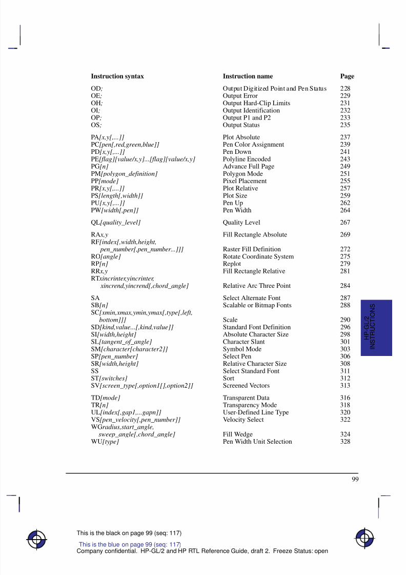
8/12/2019 HPGL2-RTL ReferenceGuide 5961-3526 540pages Sep96
http://slidepdf.com/reader/full/hpgl2-rtl-referenceguide-5961-3526-540pages-sep96 117/539
8/12/2019 HPGL2-RTL ReferenceGuide 5961-3526 540pages Sep96
http://slidepdf.com/reader/full/hpgl2-rtl-referenceguide-5961-3526-540pages-sep96 118/539
100
This is the black on page 100 (seq: 118)
Company confidential. HP-GL/2 and HP RTL Reference Guide, draft 2. Freeze Status: open
AA, Arc Absolute
Purpose
To draw an arc, using absolute coordinates, which starts at the current pen location and pivotsaround the specified center point.
Syntax
AA X center ,Y center ,sweep_angle[,chord_angle][;]
Á Á Á Á Á Á Á
Á Á Á Á Á Á Á
ParameterÁ Á Á Á Á Á
Á Á Á Á Á Á
FormatÁ Á Á Á Á Á Á Á
Á Á Á Á Á Á Á Á
Functional RangeÁ Á Á Á Á Á Á Á
Á Á Á Á Á Á Á Á
Parameter Default
Á Á Á Á Á Á Á
Á Á Á Á Á Á Á
Á Á Á Á Á Á Á
X center ,Y center Á Á Á Á Á Á
Á
Á Á Á Á Á
Á Á Á Á Á Á
current units Á Á Á Á Á Á Á Á
Á
Á Á Á Á Á Á Á
Á Á Á Á Á Á Á Á
device-dependent (at least –223 to 223 – 1)
Á Á Á Á Á Á Á Á
Á
Á Á Á Á Á Á Á
Á Á Á Á Á Á Á Á
no default
Á Á Á Á Á Á Á
Á Á Á Á Á Á Á
sweep_angle Á Á Á Á Á Á
Á Á Á Á Á Á
clamped real Á Á Á Á Á Á Á Á
Á Á Á Á Á Á Á Á
–32 768 to 32 767 Á Á Á Á Á Á Á Á
Á Á Á Á Á Á Á Á
no default
Á Á Á Á Á Á Á
Á Á Á Á Á Á Á
Á Á Á Á Á Á Á
chord_angle*Á Á Á Á Á Á
Á Á Á Á Á Á
Á Á Á Á Á Á
clamped real Á Á Á Á Á Á Á Á
Á Á Á Á Á Á Á Á
Á Á Á Á Á Á Á Á
device-dependent (at least 0 to 180)
Á Á Á Á Á Á Á Á
Á Á Á Á Á Á Á Á
Á Á Á Á Á Á Á Á
device-dependent (usually 5)
* If you have used the “CT1” instruction, the chord_angle is interpreted as a deviation dis-tance in current units; see the CT instruction on page 133.
Group
This instruction is in the Vector Group.
Use
The AA instruction draws an arc starting at the current pen location using the current pen up/ down status and line type and attributes. After drawing the arc, the pen location is updated tothe end of the arc; the carriage-return point (see page 66) is moved to the end of the arc.
Note: Do not use an adaptive line type when drawing arcs with small chord angles. The deviceattempts to draw the complete pattern in every chord (there are 72 chords in a circle using thedefault chord angle).
Xcenter, Ycenter: Specify the absolute location of the center of the arc. (The center of thearc is the center of the circle that would be drawn if the arc was 360.) Coordinates areinterpreted in current units: as user-units when scaling is on; as plotter-units when scalingis off. If current scaling is not isotropic, the arc drawn is elliptical rather than circular.
sweep_angle: Specifies in degrees the angle through which the arc is drawn. A positiveangle is drawn in a positive direction (counter-clockwise rotation); a negative angle isdrawn in the negative direction (clockwise rotation). All values outside the range –360 to+360 are converted modulo 360.
chord_angle: Specifies, in degrees, the chord angle used to draw the arc. The default is achord angle of 5. The chord_angle specifies the maximum angle created when lines fromeach end of the chord intersect the center point of the circle (see Figure 54). The smallerthe chord angle, the smoother the curve. The useful range is from 0.0 to 180.0. A chord
This is the blue on page 100 (seq: 118)
AA Instruction
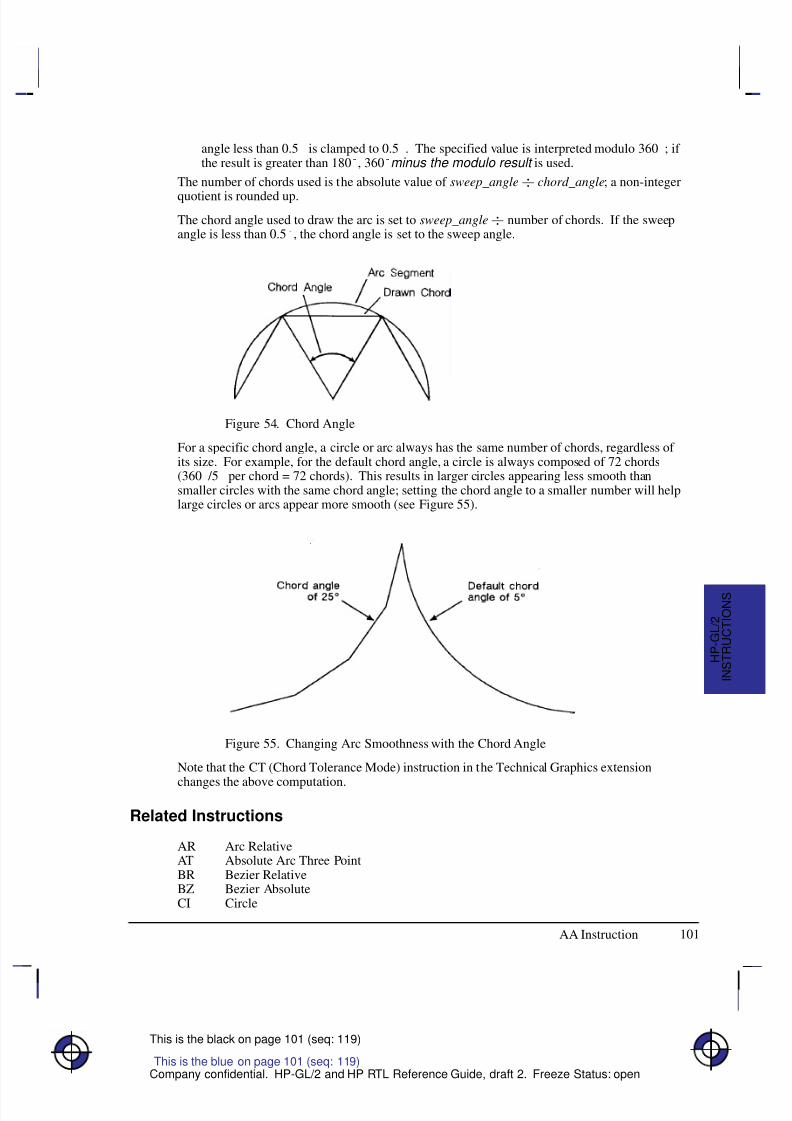
8/12/2019 HPGL2-RTL ReferenceGuide 5961-3526 540pages Sep96
http://slidepdf.com/reader/full/hpgl2-rtl-referenceguide-5961-3526-540pages-sep96 119/539
101
This is the black on page 101 (seq: 119)
Company confidential. HP-GL/2 and HP RTL Reference Guide, draft 2. Freeze Status: open
angle less than 0.5 is clamped to 0.5. The specified value is interpreted modulo 360; if the result is greater than 180, 360minus the modulo result is used.
The number of chords used is the absolute value of sweep_angle chord_angle; a non-integer
quotient is rounded up.
The chord angle used to draw the arc is set to sweep_angle number of chords. If the sweepangle is less than 0.5, the chord angle is set to the sweep angle.
Figure 54. Chord Angle
For a specific chord angle, a circle or arc always has the same number of chords, regardless of its size. For example, for the default chord angle, a circle is always composed of 72 chords(360 /5 per chord = 72 chords). This results in larger circles appearing less smooth thansmaller circles with the same chord angle; setting the chord angle to a smaller number will helplarge circles or arcs appear more smooth (see Figure 55).
Figure 55. Changing Arc Smoothness with the Chord Angle
Note that the CT (Chord Tolerance Mode) instruction in the Technical Graphics extension
changes the above computation.
Related Instructions
AR Arc RelativeAT Absolute Arc Three PointBR Bezier RelativeBZ Bezier AbsoluteCI Circle
This is the blue on page 101 (seq: 119)
AA Instruction
I N S T R U C T I O N S
H P - G L / 2
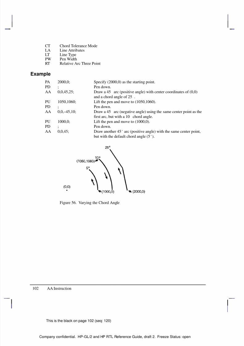
8/12/2019 HPGL2-RTL ReferenceGuide 5961-3526 540pages Sep96
http://slidepdf.com/reader/full/hpgl2-rtl-referenceguide-5961-3526-540pages-sep96 120/539
102
This is the black on page 102 (seq: 120)
Company confidential. HP-GL/2 and HP RTL Reference Guide, draft 2. Freeze Status: open
CT Chord Tolerance ModeLA Line AttributesLT Line Type
PW Pen WidthRT Relative Arc Three Point
Example
PA 2000,0; Specify (2000,0) as the starting point.
PD ; Pen down.
AA 0,0,45,25; Draw a 45 arc (positive angle) with center coordinates of (0,0)
and a chord angle of 25.
PU 1050,1060; Lift the pen and move to (1050,1060).
PD ; Pen down.
AA 0,0,–45,10; Draw a 45 arc (negative angle) using the same center point as the
first arc, but with a 10 chord angle.
PU 1000,0; Lift the pen and move to (1000,0).PD ; Pen down.
AA 0,0,45; Draw another 45 arc (positive angle) with the same center point,
but with the default chord angle (5).
Figure 56. Varying the Chord Angle
AA Instruction
8/12/2019 HPGL2-RTL ReferenceGuide 5961-3526 540pages Sep96
http://slidepdf.com/reader/full/hpgl2-rtl-referenceguide-5961-3526-540pages-sep96 121/539
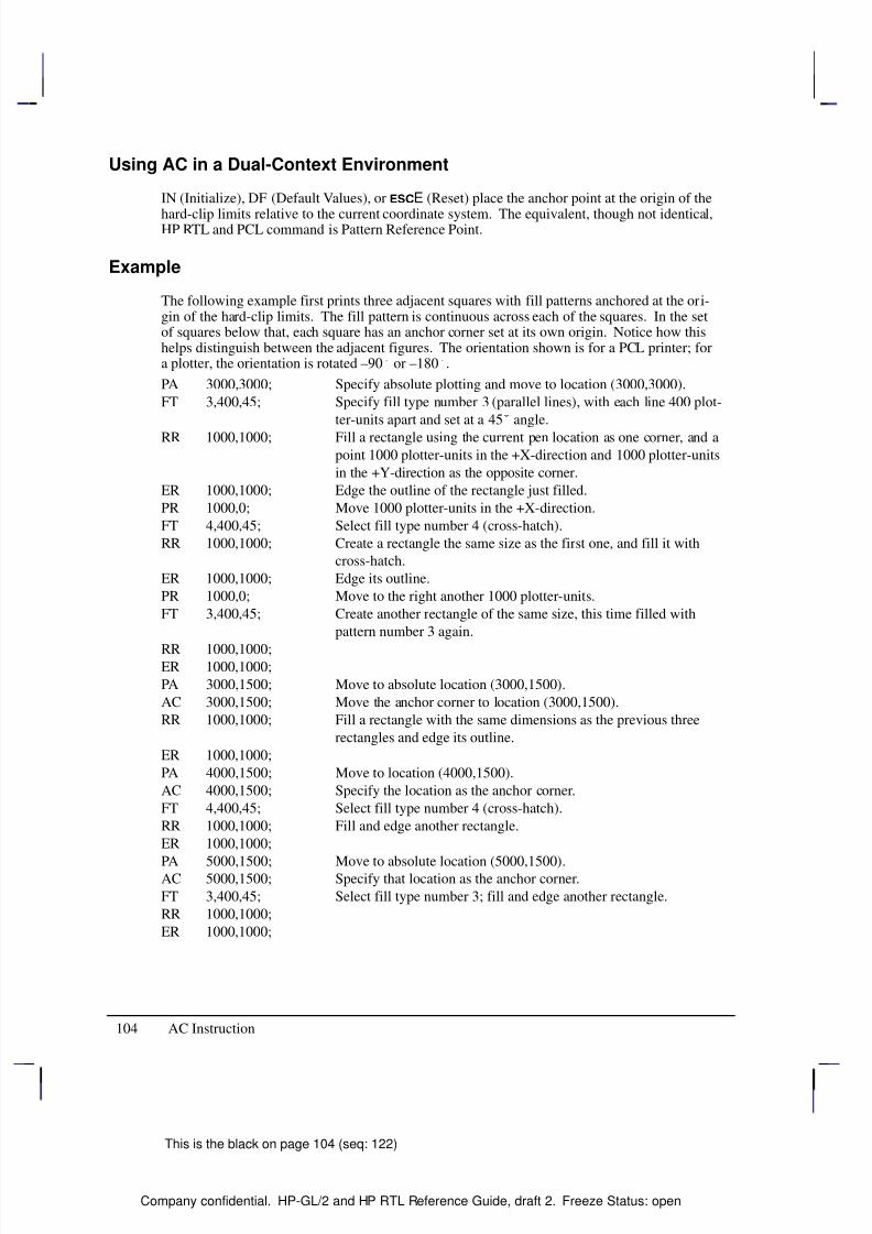
8/12/2019 HPGL2-RTL ReferenceGuide 5961-3526 540pages Sep96
http://slidepdf.com/reader/full/hpgl2-rtl-referenceguide-5961-3526-540pages-sep96 122/539
104
This is the black on page 104 (seq: 122)
Company confidential. HP-GL/2 and HP RTL Reference Guide, draft 2. Freeze Status: open
Using AC in a Dual-Context Environment
IN (Initialize), DF (Default Values), or E (Reset) place the anchor point at the origin of the
hard-clip limits relative to the current coordinate system. The equivalent, though not identical,HP RTL and PCL command is Pattern Reference Point.
Example
The following example first prints three adjacent squares with fill patterns anchored at the ori-gin of the hard-clip limits. The fill pattern is continuous across each of the squares. In the setof squares below that, each square has an anchor corner set at its own origin. Notice how thishelps distinguish between the adjacent figures. The orientation shown is for a PCL printer; fora plotter, the orientation is rotated –90 or –180.
PA 3000,3000; Specify absolute plotting and move to location (3000,3000).
FT 3,400,45; Specify fill type number 3 (parallel lines), with each line 400 plot-
ter-units apart and set at a 45 angle.
RR 1000,1000; Fill a rectangle using the current pen location as one corner, and apoint 1000 plotter-units in the +X-direction and 1000 plotter-units
in the +Y-direction as the opposite corner.
ER 1000,1000; Edge the outline of the rectangle just filled.
PR 1000,0; Move 1000 plotter-units in the +X-direction.
FT 4,400,45; Select fill type number 4 (cross-hatch).
RR 1000,1000; Create a rectangle the same size as the first one, and fill it with
cross-hatch.
ER 1000,1000; Edge its outline.
PR 1000,0; Move to the right another 1000 plotter-units.
FT 3,400,45; Create another rectangle of the same size, this time filled with
pattern number 3 again.
RR 1000,1000;ER 1000,1000;
PA 3000,1500; Move to absolute location (3000,1500).
AC 3000,1500; Move the anchor corner to location (3000,1500).
RR 1000,1000; Fill a rectangle with the same dimensions as the previous three
rectangles and edge its outline.
ER 1000,1000;
PA 4000,1500; Move to location (4000,1500).
AC 4000,1500; Specify the location as the anchor corner.
FT 4,400,45; Select fill type number 4 (cross-hatch).
RR 1000,1000; Fill and edge another rectangle.
ER 1000,1000;
PA 5000,1500; Move to absolute location (5000,1500).AC 5000,1500; Specify that location as the anchor corner.
FT 3,400,45; Select fill type number 3; fill and edge another rectangle.
RR 1000,1000;
ER 1000,1000;
AC Instruction
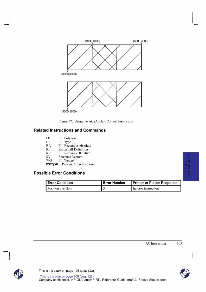
8/12/2019 HPGL2-RTL ReferenceGuide 5961-3526 540pages Sep96
http://slidepdf.com/reader/full/hpgl2-rtl-referenceguide-5961-3526-540pages-sep96 123/539
105
This is the black on page 105 (seq: 123)
Company confidential. HP-GL/2 and HP RTL Reference Guide, draft 2. Freeze Status: open
Figure 57. Using the AC (Anchor Corner) Instruction
Related Instructions and Commands
FP Fill PolygonFT Fill TypeRA Fill Rectangle AbsoluteRF Raster Fill Definition
RR Fill Rectangle RelativeSV Screened VectorsWG Fill Wedge*p#R Pattern Reference Point
Possible Error Conditions
Error Condition Error Number Printer or Plotter Response
Position overflow 3 Ignores instruction.
This is the blue on page 105 (seq: 123)
AC Instruction
I N S T R U C T I O N S
H P - G L / 2
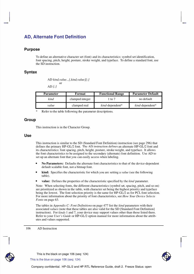
8/12/2019 HPGL2-RTL ReferenceGuide 5961-3526 540pages Sep96
http://slidepdf.com/reader/full/hpgl2-rtl-referenceguide-5961-3526-540pages-sep96 124/539
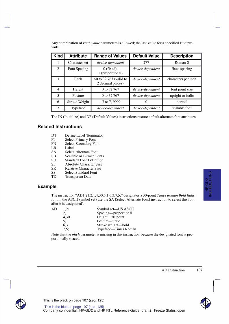
8/12/2019 HPGL2-RTL ReferenceGuide 5961-3526 540pages Sep96
http://slidepdf.com/reader/full/hpgl2-rtl-referenceguide-5961-3526-540pages-sep96 125/539
107
This is the black on page 107 (seq: 125)
Company confidential. HP-GL/2 and HP RTL Reference Guide, draft 2. Freeze Status: open
Any combination of kind, value parameters is allowed; the last value for a specified kind pre-vails.
Kind Attribute Range of Values Default Value Description1 Character set device-dependent 277 Roman-8
2 Font Spacing 0 (fixed),1 (proportional)
device-dependent fixed spacing
3 Pitch >0 to 32 767 (valid to2 decimal places)
device-dependent characters per inch
4 Height 0 to 32 767 device-dependent font point size
5 Posture 0 to 32 767 device-dependent upright or italic
6 Stroke Weight –7 to 7, 9999 0 normal
7 Typeface device-dependent device-dependent scalable font
The IN (Initialize) and DF (Default Values) instructions restore default alternate font attributes.
Related Instructions
DT Define Label TerminatorFI Select Primary FontFN Select Secondary FontLB LabelSA Select Alternate FontSB Scalable or Bitmap FontsSD Standard Font DefinitionSI Absolute Character Size
SR Relative Character SizeSS Select Standard FontTD Transparent Data
Example
The instruction “AD1,21,2,1,4,30,5,1,6,3,7,5;” designates a 30-point Times Roman Bold Italicfont in the ASCII symbol set (use the SA [Select Alternate Font] instruction to select this fontafter it is designated):
AD 1,21 Symbol set—US ASCII2,1 Spacing—proportional4,30 Height—30-point5,1 Posture—italic6,3 Stroke weight—bold7,5; Typeface—Times Roman
Note that the pitch parameter is missing in this instruction because the designated font is pro-portionally spaced.
This is the blue on page 107 (seq: 125)
AD Instruction
I N S T R U C T I O N S
H P - G L / 2
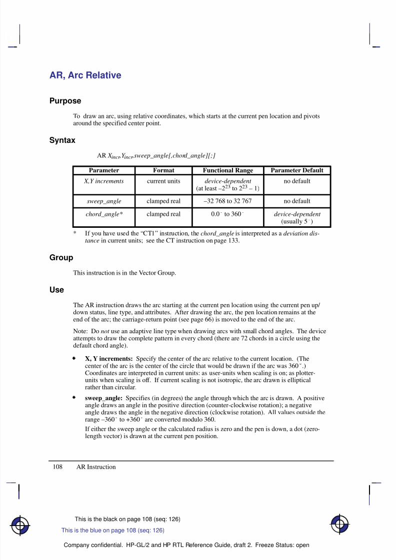
8/12/2019 HPGL2-RTL ReferenceGuide 5961-3526 540pages Sep96
http://slidepdf.com/reader/full/hpgl2-rtl-referenceguide-5961-3526-540pages-sep96 126/539
108
This is the black on page 108 (seq: 126)
Company confidential. HP-GL/2 and HP RTL Reference Guide, draft 2. Freeze Status: open
AR, Arc Relative
Purpose
To draw an arc, using relative coordinates, which starts at the current pen location and pivotsaround the specified center point.
Syntax
AR X incr ,Y incr ,sweep_angle[,chord_angle][;]
Á Á Á Á Á Á Á
Á Á Á Á Á Á Á
ParameterÁ Á Á Á Á Á
Á Á Á Á Á Á
FormatÁ Á Á Á Á Á Á Á
Á Á Á Á Á Á Á Á
Functional RangeÁ Á Á Á Á Á Á Á
Á Á Á Á Á Á Á Á
Parameter Default
Á Á Á Á Á Á Á
Á Á Á Á Á Á Á
Á Á Á Á Á Á Á
X,Y increments Á Á Á Á Á Á
Á
Á Á Á Á Á
Á Á Á Á Á Á
current units Á Á Á Á Á Á Á Á
Á
Á Á Á Á Á Á Á
Á Á Á Á Á Á Á Á
device-dependent (at least –223 to 223 – 1)
Á Á Á Á Á Á Á Á
Á
Á Á Á Á Á Á Á
Á Á Á Á Á Á Á Á
no default
Á Á Á Á Á Á Á
Á Á Á Á Á Á Á
sweep_angle Á Á Á Á Á Á
Á Á Á Á Á Á
clamped real Á Á Á Á Á Á Á Á
Á Á Á Á Á Á Á Á
–32 768 to 32 767 Á Á Á Á Á Á Á Á
Á Á Á Á Á Á Á Á
no default
Á Á Á Á Á Á Á
Á Á Á Á Á Á Á
Á Á Á Á Á Á Á
chord_angle*Á Á Á Á Á Á
Á Á Á Á Á Á
Á Á Á Á Á Á
clamped real Á Á Á Á Á Á Á Á
Á Á Á Á Á Á Á Á
Á Á Á Á Á Á Á Á
0.0 to 360 Á Á Á Á Á Á Á Á
Á Á Á Á Á Á Á Á
Á Á Á Á Á Á Á Á
device-dependent (usually 5)
* If you have used the “CT1” instruction, the chord_angle is interpreted as a deviation dis-tance in current units; see the CT instruction on page 133.
Group
This instruction is in the Vector Group.
Use
The AR instruction draws the arc starting at the current pen location using the current pen up/ down status, line type, and attributes. After drawing the arc, the pen location remains at theend of the arc; the carriage-return point (see page 66) is moved to the end of the arc.
Note: Do not use an adaptive line type when drawing arcs with small chord angles. The deviceattempts to draw the complete pattern in every chord (there are 72 chords in a circle using thedefault chord angle).
X, Y increments: Specify the center of the arc relative to the current location. (Thecenter of the arc is the center of the circle that would be drawn if the arc was 360.)Coordinates are interpreted in current units: as user-units when scaling is on; as plotter-units when scaling is off. If current scaling is not isotropic, the arc drawn is ellipticalrather than circular.
sweep_angle: Specifies (in degrees) the angle through which the arc is drawn. A positiveangle draws an angle in the positive direction (counter-clockwise rotation); a negativeangle draws the angle in the negative direction (clockwise rotation). All values outside therange –360 to +360 are converted modulo 360.
If either the sweep angle or the calculated radius is zero and the pen is down, a dot (zero-length vector) is drawn at the current pen position.
This is the blue on page 108 (seq: 126)
AR Instruction
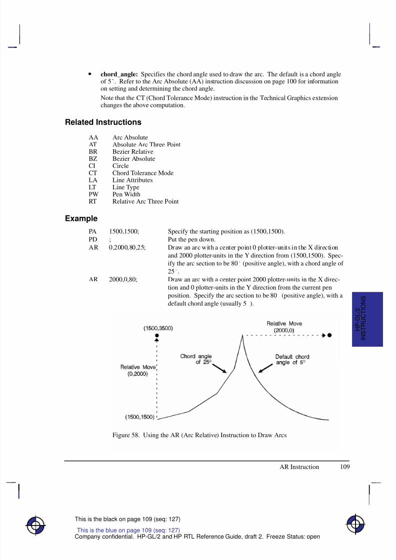
8/12/2019 HPGL2-RTL ReferenceGuide 5961-3526 540pages Sep96
http://slidepdf.com/reader/full/hpgl2-rtl-referenceguide-5961-3526-540pages-sep96 127/539
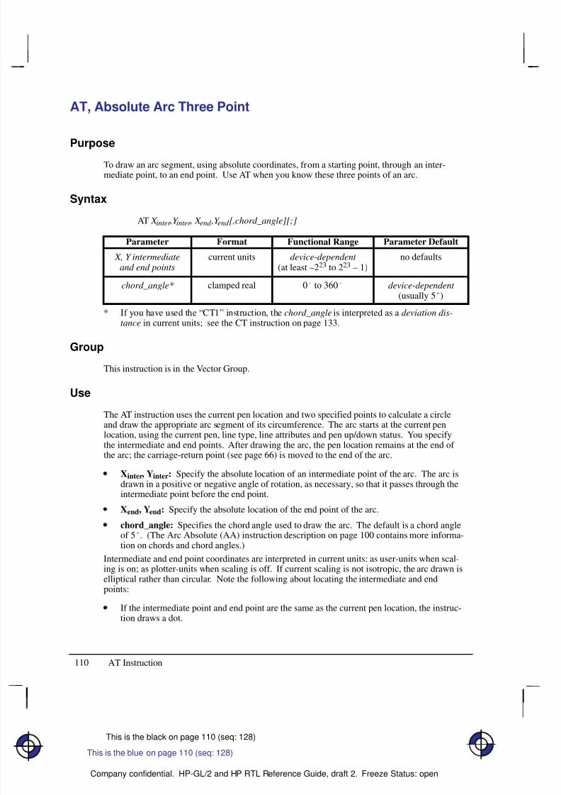
8/12/2019 HPGL2-RTL ReferenceGuide 5961-3526 540pages Sep96
http://slidepdf.com/reader/full/hpgl2-rtl-referenceguide-5961-3526-540pages-sep96 128/539
110
This is the black on page 110 (seq: 128)
Company confidential. HP-GL/2 and HP RTL Reference Guide, draft 2. Freeze Status: open
AT, Absolute Arc Three Point
Purpose
To draw an arc segment, using absolute coordinates, from a starting point, through an inter-mediate point, to an end point. Use AT when you know these three points of an arc.
Syntax
AT X inter ,Y inter , X end ,Y end [,chord_angle][;]
Á Á Á Á Á Á Á
Á Á Á Á Á Á Á
ParameterÁ Á Á Á Á Á
Á Á Á Á Á Á
FormatÁ Á Á Á Á Á Á Á
Á Á Á Á Á Á Á Á
Functional RangeÁ Á Á Á Á Á Á Á
Á Á Á Á Á Á Á Á
Parameter Default
Á Á Á Á Á Á Á
Á Á Á Á Á Á Á
Á Á Á Á Á Á Á
X, Y intermediateand end points
Á Á Á Á Á Á
Á
Á Á Á Á Á
Á Á Á Á Á Á
current units Á Á Á Á Á Á Á Á
Á
Á Á Á Á Á Á Á
Á Á Á Á Á Á Á Á
device-dependent (at least –223 to 223 – 1)
Á Á Á Á Á Á Á Á
Á
Á Á Á Á Á Á Á
Á Á Á Á Á Á Á Á
no defaults
Á Á Á Á Á Á Á
Á Á Á Á Á Á Á
Á Á Á Á Á Á Á
chord_angle* Á Á Á Á Á Á
Á
Á Á Á Á Á
Á Á Á Á Á Á
clamped real Á Á Á Á Á Á Á Á
Á
Á Á Á Á Á Á Á
Á Á Á Á Á Á Á Á
0 to 360 Á Á Á Á Á Á Á Á
Á
Á Á Á Á Á Á Á
Á Á Á Á Á Á Á Á
device-dependent (usually 5)
* If you have used the “CT1” instruction, the chord_angle is interpreted as a deviation dis-tance in current units; see the CT instruction on page 133.
Group
This instruction is in the Vector Group.
Use
The AT instruction uses the current pen location and two specified points to calculate a circleand draw the appropriate arc segment of its circumference. The arc starts at the current penlocation, using the current pen, line type, line attributes and pen up/down status. You specifythe intermediate and end points. After drawing the arc, the pen location remains at the end of the arc; the carriage-return point (see page 66) is moved to the end of the arc.
Xinter, Yinter: Specify the absolute location of an intermediate point of the arc. The arc isdrawn in a positive or negative angle of rotation, as necessary, so that it passes through theintermediate point before the end point.
Xend, Yend: Specify the absolute location of the end point of the arc.
chord_angle: Specifies the chord angle used to draw the arc. The default is a chord angleof 5. (The Arc Absolute (AA) instruction description on page 100 contains more informa-tion on chords and chord angles.)
Intermediate and end point coordinates are interpreted in current units: as user-units when scal-ing is on; as plotter-units when scaling is off. If current scaling is not isotropic, the arc drawn iselliptical rather than circular. Note the following about locating the intermediate and endpoints:
If the intermediate point and end point are the same as the current pen location, the instruc-tion draws a dot.
This is the blue on page 110 (seq: 128)
AT Instruction
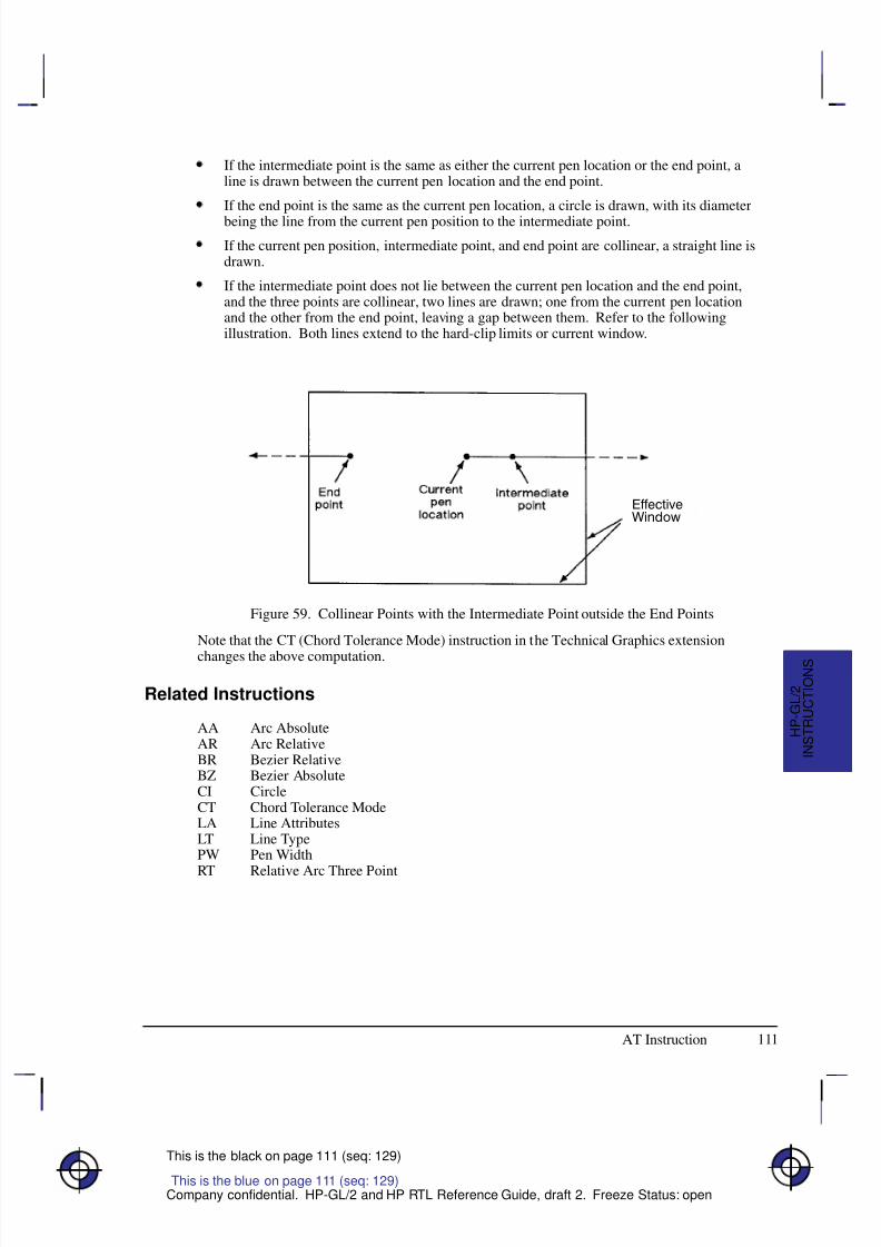
8/12/2019 HPGL2-RTL ReferenceGuide 5961-3526 540pages Sep96
http://slidepdf.com/reader/full/hpgl2-rtl-referenceguide-5961-3526-540pages-sep96 129/539
111
This is the black on page 111 (seq: 129)
Company confidential. HP-GL/2 and HP RTL Reference Guide, draft 2. Freeze Status: open
If the intermediate point is the same as either the current pen location or the end point, aline is drawn between the current pen location and the end point.
If the end point is the same as the current pen location, a circle is drawn, with its diameter
being the line from the current pen position to the intermediate point.
If the current pen position, intermediate point, and end point are collinear, a straight line isdrawn.
If the intermediate point does not lie between the current pen location and the end point,and the three points are collinear, two lines are drawn; one from the current pen locationand the other from the end point, leaving a gap between them. Refer to the followingillustration. Both lines extend to the hard-clip limits or current window.
Figure 59. Collinear Points with the Intermediate Point outside the End Points
Note that the CT (Chord Tolerance Mode) instruction in the Technical Graphics extension
changes the above computation.
Related Instructions
AA Arc AbsoluteAR Arc RelativeBR Bezier RelativeBZ Bezier AbsoluteCI CircleCT Chord Tolerance ModeLA Line AttributesLT Line TypePW Pen Width
RT Relative Arc Three Point
This is the blue on page 111 (seq: 129)
AT Instruction
I N S T R U C T I O N S
H P - G L / 2
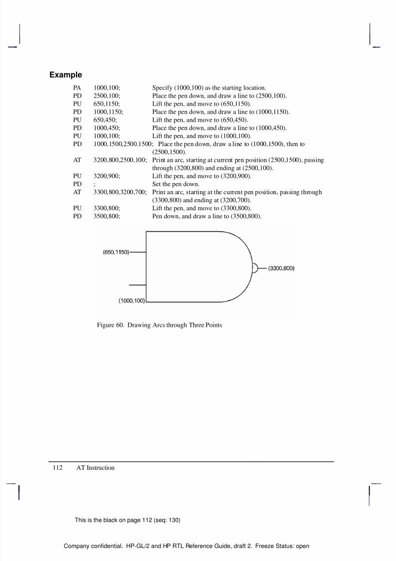
8/12/2019 HPGL2-RTL ReferenceGuide 5961-3526 540pages Sep96
http://slidepdf.com/reader/full/hpgl2-rtl-referenceguide-5961-3526-540pages-sep96 130/539
112
This is the black on page 112 (seq: 130)
Company confidential. HP-GL/2 and HP RTL Reference Guide, draft 2. Freeze Status: open
Example
PA 1000,100; Specify (1000,100) as the starting location.
PD 2500,100; Place the pen down, and draw a line to (2500,100).PU 650,1150; Lift the pen, and move to (650,1150).
PD 1000,1150; Place the pen down, and draw a line to (1000,1150).
PU 650,450; Lift the pen, and move to (650,450).
PD 1000,450; Place the pen down, and draw a line to (1000,450).
PU 1000,100; Lift the pen, and move to (1000,100).
PD 1000,1500,2500,1500; Place the pen down, draw a line to (1000,1500), then to
(2500,1500).
AT 3200,800,2500,100; Print an arc, starting at current pen position (2500,1500), passing
through (3200,800) and ending at (2500,100).
PU 3200,900; Lift the pen, and move to (3200,900).
PD ; Set the pen down.
AT 3300,800,3200,700; Print an arc, starting at the current pen position, passing through
(3300,800) and ending at (3200,700).
PU 3300,800; Lift the pen, and move to (3300,800).
PD 3500,800; Pen down, and draw a line to (3500,800).
Figure 60. Drawing Arcs through Three Points
AT Instruction
8/12/2019 HPGL2-RTL ReferenceGuide 5961-3526 540pages Sep96
http://slidepdf.com/reader/full/hpgl2-rtl-referenceguide-5961-3526-540pages-sep96 131/539
113
This is the black on page 113 (seq: 131)
Company confidential. HP-GL/2 and HP RTL Reference Guide, draft 2. Freeze Status: open
BP, Begin Plot
Purpose
To place the device into the picture header state and indicate the beginning of a new plot.
Syntax
BP kind,value...[,kind,value][;]or
BP[;]
Á Á Á Á Á Á Á
ParameterÁ Á Á Á Á Á Á
FormatÁ Á Á Á Á Á Á Á
Functional RangeÁ Á Á Á Á Á Á
Parameter DefaultÁ Á Á Á Á Á Á
Á
Á Á Á Á Á Á
Á Á Á Á Á Á Á
kind
Á Á Á Á Á Á Á
Á
Á Á Á Á Á Á
Á Á Á Á Á Á Á
clamped integerÁ Á Á Á Á Á Á Á
Á
Á Á Á Á Á Á Á
Á Á Á Á Á Á Á Á
1 to 5Á Á Á Á Á Á Á
Á
Á Á Á Á Á Á
Á Á Á Á Á Á Á
no default
Á Á Á Á Á Á Á
Á Á Á Á Á Á Á
value Á Á Á Á Á Á Á
Á Á Á Á Á Á Á
kind -dependent Á Á Á Á Á Á Á Á
Á Á Á Á Á Á Á Á
kind -dependent Á Á Á Á Á Á Á
Á Á Á Á Á Á Á
kind -dependent
Group
This instruction is in the Technical Graphics Extension.
Use
BP produces the equivalent of PG (Advance Full Page) and IN (Initialize). It begins a new plotregardless of whether the previous plot was terminated. It makes the previous plot unavail-able—that is, BP followed by RP (Replot) produces nothing.
No parameters: all values are defaulted.kind and value parameters: The kind parameter is a clamped integer between 1 and 5; thevalue parameter is kind-dependent. These parameters must be specified in pairs, as shownin the table on the next page.
For a buffered raster device, the default behavior of BP is to discard the previous plot if it hasnot yet been printed with either PG or RP. The instruction “BP4,1” allows overriding the de-fault behavior by generating a PG. For a plotter or other “plot as you parse” device, a “4,1”pair is always NOP’d and a BP instruction always results in a conditional page advance. Forspooled plotters, the previous plot may or may not be discarded before printing if it was notproperly terminated.
BP starts a new plot and guarantees that it starts on a clean page. It performs an IN to ensurethat the plot starts in a known state, and puts the device into picture header state.
BP starts a new plot regardless of whether the last plot was terminated properly, even when oneor more of its parameters are in error. This provides a measure of error recovery, in case thatthe previous user’s application did not complete plotting properly. The parameters specified inthe BP instruction apply only to the plot started by the current BP.
BP is recognized in polygon mode (the polygon buffer is cleared), but not in label mode.
This is the blue on page 113 (seq: 131)
BP Instruction
I N S T R U C T I O N S
H P - G L / 2
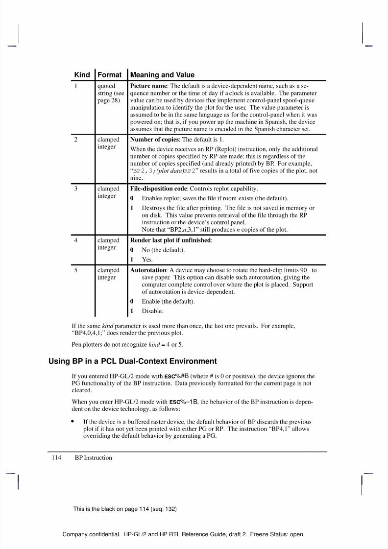
8/12/2019 HPGL2-RTL ReferenceGuide 5961-3526 540pages Sep96
http://slidepdf.com/reader/full/hpgl2-rtl-referenceguide-5961-3526-540pages-sep96 132/539
114
This is the black on page 114 (seq: 132)
Company confidential. HP-GL/2 and HP RTL Reference Guide, draft 2. Freeze Status: open
Kind Format Meaning and Value
1 quoted
string (seepage 28)
Picture name: The default is a device-dependent name, such as a se-
quence number or the time of day if a clock is available. The parametervalue can be used by devices that implement control-panel spool-queuemanipulation to identify the plot for the user. The value parameter isassumed to be in the same language as for the control-panel when it waspowered on; that is, if you power up the machine in Spanish, the deviceassumes that the picture name is encoded in the Spanish character set.
2 clampedinteger
Number of copies: The default is 1.
When the device receives an RP (Replot) instruction, only the additionalnumber of copies specified by RP are made; this is regardless of thenumber of copies specified (and already printed) by BP. For example,“BP2,3;(plot data)RP2” results in a total of five copies of the plot, notnine.
3 clampedinteger
File-disposition code: Controls replot capability.
0 Enables replot; saves the file if room exists (the default).
1 Destroys the file after printing. The file is not saved in memory oron disk. This value prevents retrieval of the file through the RPinstruction or the device’s control panel.Note that “BP2,n,3,1” still produces n copies of the plot.
4 clampedinteger
Render last plot if unfinished:
0 No (the default).
1 Yes.
5 clampedinteger
Autorotation: A device may choose to rotate the hard-clip limits 90 tosave paper. This option can disable such autorotation, giving thecomputer complete control over where the plot is placed. Supportof autorotation is device-dependent.
0 Enable (the default).
1 Disable.
If the same kind parameter is used more than once, the last one prevails. For example,“BP4,0,4,1;” does render the previous plot.
Pen plotters do not recognize kind = 4 or 5.
Using BP in a PCL Dual-Context Environment
If you entered HP-GL/2 mode with %#B (where # is 0 or positive), the device ignores the
PG functionality of the BP instruction. Data previously formatted for the current page is notcleared.
When you enter HP-GL/2 mode with %–1B, the behavior of the BP instruction is depen-dent on the device technology, as follows:
If the device is a buffered raster device, the default behavior of BP discards the previousplot if it has not yet been printed with either PG or RP. The instruction “BP4,1” allowsoverriding the default behavior by generating a PG.
BP Instruction

8/12/2019 HPGL2-RTL ReferenceGuide 5961-3526 540pages Sep96
http://slidepdf.com/reader/full/hpgl2-rtl-referenceguide-5961-3526-540pages-sep96 133/539
115
This is the black on page 115 (seq: 133)
Company confidential. HP-GL/2 and HP RTL Reference Guide, draft 2. Freeze Status: open
For a pen plotter or any device that plots data as it is received, a “BP4,1” is always ignoredand a BP instruction always results in a conditional page advance (if the page has beenplotted on, the page is advanced). %#B is ignored.
Using BP in a Dual-Context HP RTL Environment
If you use the BP instruction in a dual-context HP RTL device, the device performs only the PGfunction of the instruction.
Related Instructions and Commands
IN InitializePG Advance PageRP Replot%#B Enter HP-GL/2 mode command from PCL or HP RTL
BP Instruction
This is the blue on page 115 (seq: 133)
BP Instruction
I N S T R U C T I O N S
H P - G L / 2
8/12/2019 HPGL2-RTL ReferenceGuide 5961-3526 540pages Sep96
http://slidepdf.com/reader/full/hpgl2-rtl-referenceguide-5961-3526-540pages-sep96 134/539
116
This is the black on page 116 (seq: 134)
Company confidential. HP-GL/2 and HP RTL Reference Guide, draft 2. Freeze Status: open
BR, Bezier Relative
Purpose
To draw a series of Bezier curves using relative coordinates.
Syntax
BR X1,Y1,X2,Y2,X3,Y3,...[X1,Y1,X2,Y2,X3,Y3][;]
Á Á Á Á Á Á Á Á
Á Á Á Á Á Á Á Á
Parameter Á Á Á Á Á
Á Á Á Á Á
Format Á Á Á Á Á Á Á Á
Á Á Á Á Á Á Á Á
Functional Range Á Á Á Á Á Á Á Á
Á Á Á Á Á Á Á Á
Parameter DefaultÁ Á Á Á Á Á Á Á
Á Á Á Á Á Á Á Á
Á Á Á Á Á Á Á Á
X, Y incrementsÁ Á Á Á Á
Á
Á Á Á Á
Á Á Á Á Á
current unitsÁ Á Á Á Á Á Á Á
Á
Á Á Á Á Á Á Á
Á Á Á Á Á Á Á Á
device-dependent (at least –223 to 223–1)
Á Á Á Á Á Á Á Á
Á
Á Á Á Á Á Á Á
Á Á Á Á Á Á Á Á
no default
Group
This instruction is in the Advanced Drawing Extension.
Use
BR draws a Bezier curve using the present pen position as the first control point, and the de-fined control points as increments. All curve control points are relative to the first control pointof that curve.
X,Y coordinates: Specify the location of the second (X1,Y1), third (X2,Y2), and fourth(X3,Y3) control points in relative increments, that is, all of these values are relative to thecurrent pen location at the start of the Bezier curve.
The curves are drawn with the current pen, line type, line attributes, and pen state (up or down);and they are clipped to the hard-clip limits and the soft-clip window. The current pen locationis updated to the end point of the curve at the termination of each Bezier curve defined by theinstruction. After each new Bezier curve, the last control point is used by the next Bezier curveas its first control point. The carriage-return point (see page 66) is moved to the last X,Y.
After the first four control points are defined (one present-position control point and three con-trol points) the optional parameters define subsequent Bezier curves by adding three additionalcontrol points.
BR is allowed in Polygon Mode. The first chord after “PM1” is not treated as a pen-up move.
Related Instructions
AA Arc AbsoluteAR Arc RelativeAT Absolute Arc Three PointBZ Bezier AbsoluteCI CircleLA Line AttributesLT Line TypePW Pen WidthRT Relative Arc Three Point
This is the blue on page 116 (seq: 134)
BR Instruction
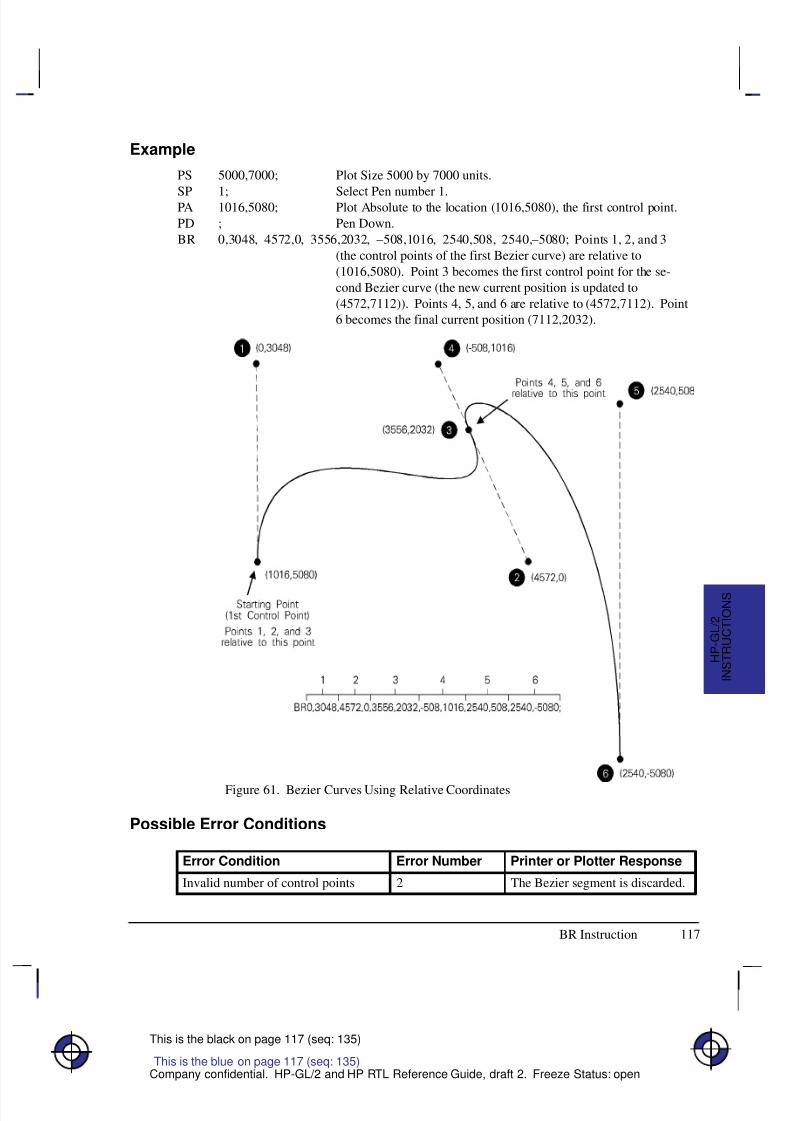
8/12/2019 HPGL2-RTL ReferenceGuide 5961-3526 540pages Sep96
http://slidepdf.com/reader/full/hpgl2-rtl-referenceguide-5961-3526-540pages-sep96 135/539
117
This is the black on page 117 (seq: 135)
Company confidential. HP-GL/2 and HP RTL Reference Guide, draft 2. Freeze Status: open
Example
PS 5000,7000; Plot Size 5000 by 7000 units.
SP 1; Select Pen number 1.PA 1016,5080; Plot Absolute to the location (1016,5080), the first control point.
PD ; Pen Down.
BR 0,3048, 4572,0, 3556,2032, –508,1016, 2540,508, 2540,–5080; Points 1, 2, and 3
(the control points of the first Bezier curve) are relative to
(1016,5080). Point 3 becomes the first control point for the se-
cond Bezier curve (the new current position is updated to
(4572,7112)). Points 4, 5, and 6 are relative to (4572,7112). Point
6 becomes the final current position (7112,2032).
Figure 61. Bezier Curves Using Relative Coordinates
Possible Error Conditions
Error Condition Error Number Printer or Plotter Response
Invalid number of control points 2 The Bezier segment is discarded.
This is the blue on page 117 (seq: 135)
BR Instruction
I N S T R U C T I O N S
H P - G L / 2
8/12/2019 HPGL2-RTL ReferenceGuide 5961-3526 540pages Sep96
http://slidepdf.com/reader/full/hpgl2-rtl-referenceguide-5961-3526-540pages-sep96 136/539
118
This is the black on page 118 (seq: 136)
Company confidential. HP-GL/2 and HP RTL Reference Guide, draft 2. Freeze Status: open
BZ, Bezier Absolute
Purpose
To draw a series of Bezier curves using absolute coordinates.
Syntax
BZ X1,Y1,X2,Y2,X3,Y3,...[X1,Y1,X2,Y2,X3,Y3][;]
Á Á Á Á Á Á Á Á
Á Á Á Á Á Á Á Á
Parameter Á Á Á Á Á
Á Á Á Á Á
Format Á Á Á Á Á Á Á Á
Á Á Á Á Á Á Á Á
Functional Range Á Á Á Á Á Á Á Á
Á Á Á Á Á Á Á Á
Parameter DefaultÁ Á Á Á Á Á Á Á
Á Á Á Á Á Á Á Á
X, Y coordinatesÁ Á Á Á Á
Á Á Á Á Á
current unitsÁ Á Á Á Á Á Á Á
Á Á Á Á Á Á Á Á
device-dependent Á Á Á Á Á Á Á Á
Á Á Á Á Á Á Á Á
no default
Group
This instruction is in the Advanced Drawing Extension.
Use
BZ draws a Bezier curve using the present pen position as the first control point, and the de-fined points as further control points. All curve control points are in absolute coordinates.
X, Y coordinates: Specify the location of the second (X1,Y1), third (X2,Y2), and fourth(X3,Y3) control points in absolute coordinates.
The curves are drawn with the current pen, line type, line attributes, and pen state (up or down);and they are clipped to the hard-clip limits and the soft-clip window. The current pen locationis updated to the end point of the curve at the termination of each Bezier curve defined by theinstruction. After each new Bezier curve, the last control point is used by the next Bezier curveas the first control point. The carriage-return point (see page 66) is moved to the last X,Y.
After the first four control points are defined (one present-position control point and three con-trol points) the optional parameters define subsequent Bezier curves by adding three additionalcontrol points.
BZ is allowed in Polygon Mode. The first chord after “PM1” is not treated as a pen-up move.
Related Instructions
AA Arc AbsoluteAR Arc RelativeAT Absolute Arc Three PointBR Bezier RelativeCI CircleLA Line AttributesLT Line TypePW Pen WidthRT Relative Arc Three Point
This is the blue on page 118 (seq: 136)
BZ Instruction
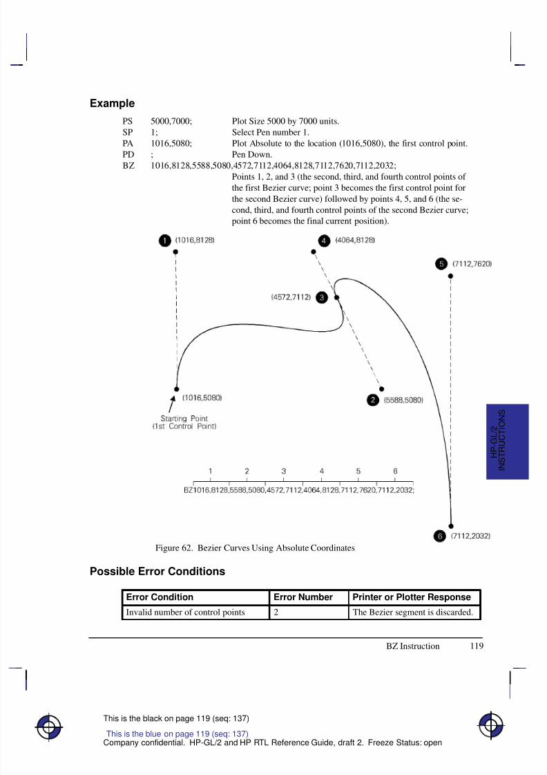
8/12/2019 HPGL2-RTL ReferenceGuide 5961-3526 540pages Sep96
http://slidepdf.com/reader/full/hpgl2-rtl-referenceguide-5961-3526-540pages-sep96 137/539
119
This is the black on page 119 (seq: 137)
Company confidential. HP-GL/2 and HP RTL Reference Guide, draft 2. Freeze Status: open
Example
PS 5000,7000; Plot Size 5000 by 7000 units.
SP 1; Select Pen number 1.PA 1016,5080; Plot Absolute to the location (1016,5080), the first control point.
PD ; Pen Down.
BZ 1016,8128,5588,5080,4572,7112,4064,8128,7112,7620,7112,2032;
Points 1, 2, and 3 (the second, third, and fourth control points of
the first Bezier curve; point 3 becomes the first control point for
the second Bezier curve) followed by points 4, 5, and 6 (the se-
cond, third, and fourth control points of the second Bezier curve;
point 6 becomes the final current position).
Figure 62. Bezier Curves Using Absolute Coordinates
Possible Error Conditions
Error Condition Error Number Printer or Plotter Response
Invalid number of control points 2 The Bezier segment is discarded.
BZ Instruction
I N S T R U C T I O N S
H P - G L / 2
This is the blue on page 119 (seq: 137)
8/12/2019 HPGL2-RTL ReferenceGuide 5961-3526 540pages Sep96
http://slidepdf.com/reader/full/hpgl2-rtl-referenceguide-5961-3526-540pages-sep96 138/539
120
This is the black on page 120 (seq: 138)
Company confidential. HP-GL/2 and HP RTL Reference Guide, draft 2. Freeze Status: open
CF, Character Fill Mode
Purpose
To specify the way scalable outline fonts are filled and edged; bitmap and stick fonts cannot beedged and can be filled only with raster fill, shading, or PCL and HP RTL cross-hatch patterns.Scalable characters may be filled with any of the fill patterns specified by the FT instruction(shading, hatching, cross-hatch, and user-defined raster fill patterns). If your device does notsupport outline fonts, this instruction may perform no operation (a NOP); pen plotters generallydo not support outline fonts.
Syntax
CF fill_mode[,edge_pen][;]or
CF [;]
Á Á Á Á Á
Á Á Á Á Á
Parameter Á Á Á Á Á Á Á
Á Á Á Á Á Á Á
Format Á Á Á Á Á Á Á Á
Á Á Á Á Á Á Á Á
Functional Range Á Á Á Á Á Á Á Á
Á Á Á Á Á Á Á Á
Parameter Default
Á Á Á Á Á
Á Á Á Á Á
fill_mode Á Á Á Á Á Á Á
Á Á Á Á Á Á Á
clamped integer Á Á Á Á Á Á Á Á
Á Á Á Á Á Á Á Á
0, 1, 2, or 3 Á Á Á Á Á Á Á Á
Á Á Á Á Á Á Á Á
0 (solid fill, no edging)Á Á Á Á Á
Á Á Á Á Á
Á Á Á Á Á
edge_penÁ Á Á Á Á Á Á
Á Á Á Á Á Á Á
Á Á Á Á Á Á Á
integerÁ Á Á Á Á Á Á Á
Á Á Á Á Á Á Á Á
Á Á Á Á Á Á Á Á
device-dependent (at least –223 to 223–1)
Á Á Á Á Á Á Á Á
Á Á Á Á Á Á Á Á
Á Á Á Á Á Á Á Á
current pen
Group
This instruction is in the Character Group.
Use
No Parameters: Defaults characters to solid fill with no edging. Equivalent to “CF0,0”.
fill_mode: Specifies how the device renders filled characters according to the followingparameter values:
0 Specifies solid fill using the current pen and edging with the specified pen (or cur-rent pen if the edge_pen parameter is not specified).
1 Specifies edging with the specified pen (or current pen if the edge_pen parameteris not specified). Characters are filled only if they cannot be edged (bitmap orstick characters), using the edge pen.
2 Specifies filled characters using the current fill type (refer to the FT instruction on
page 183). If the fill pattern does not incorporate color information, the currentlyselected pen is used. Characters are not edged; if the edge_pen parameter is speci-fied, it is ignored.
3 Specifies filled characters using the current fill type (refer to the FT instruction).If the fill pattern does not incorporate color information, the currently selected penis used. Characters are edged with the specified pen (or current pen if theedge_pen parameter is not specified).
This is the blue on page 120 (seq: 138)
CF Instruction
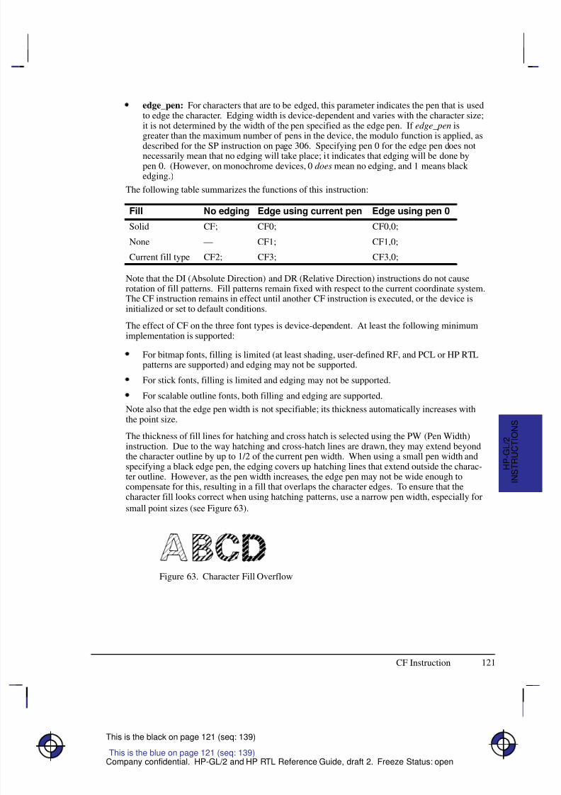
8/12/2019 HPGL2-RTL ReferenceGuide 5961-3526 540pages Sep96
http://slidepdf.com/reader/full/hpgl2-rtl-referenceguide-5961-3526-540pages-sep96 139/539
121
This is the black on page 121 (seq: 139)
Company confidential. HP-GL/2 and HP RTL Reference Guide, draft 2. Freeze Status: open
edge_pen: For characters that are to be edged, this parameter indicates the pen that is usedto edge the character. Edging width is device-dependent and varies with the character size;it is not determined by the width of the pen specified as the edge pen. If edge_pen is
greater than the maximum number of pens in the device, the modulo function is applied, asdescribed for the SP instruction on page 306. Specifying pen 0 for the edge pen does notnecessarily mean that no edging will take place; it indicates that edging will be done bypen 0. (However, on monochrome devices, 0 does mean no edging, and 1 means black edging.)
The following table summarizes the functions of this instruction:
Fill No edging Edge using current pen Edge using pen 0
Solid CF; CF0; CF0,0;
None — CF1; CF1,0;
Current fill type CF2; CF3; CF3,0;
Note that the DI (Absolute Direction) and DR (Relative Direction) instructions do not causerotation of fill patterns. Fill patterns remain fixed with respect to the current coordinate system.The CF instruction remains in effect until another CF instruction is executed, or the device isinitialized or set to default conditions.
The effect of CF on the three font types is device-dependent. At least the following minimumimplementation is supported:
For bitmap fonts, filling is limited (at least shading, user-defined RF, and PCL or HP RTLpatterns are supported) and edging may not be supported.
For stick fonts, filling is limited and edging may not be supported.
For scalable outline fonts, both filling and edging are supported.
Note also that the edge pen width is not specifiable; its thickness automatically increases with
the point size.
The thickness of fill lines for hatching and cross hatch is selected using the PW (Pen Width)instruction. Due to the way hatching and cross-hatch lines are drawn, they may extend beyondthe character outline by up to 1/2 of the current pen width. When using a small pen width andspecifying a black edge pen, the edging covers up hatching lines that extend outside the charac-ter outline. However, as the pen width increases, the edge pen may not be wide enough tocompensate for this, resulting in a fill that overlaps the character edges. To ensure that thecharacter fill looks correct when using hatching patterns, use a narrow pen width, especially for
small point sizes (see Figure 63).
Figure 63. Character Fill Overflow
CF Instruction
This is the blue on page 121 (seq: 139)
I N S T R U C T I O N S
H P - G L / 2
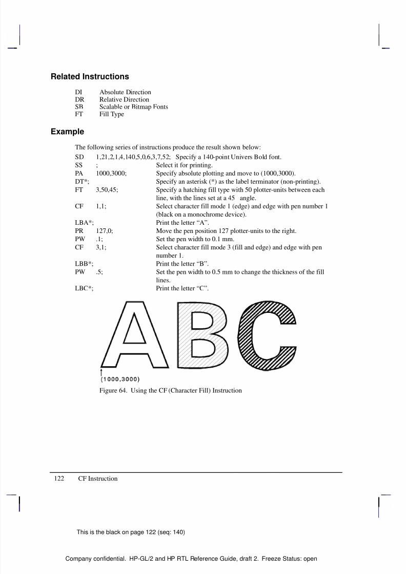
8/12/2019 HPGL2-RTL ReferenceGuide 5961-3526 540pages Sep96
http://slidepdf.com/reader/full/hpgl2-rtl-referenceguide-5961-3526-540pages-sep96 140/539
122
This is the black on page 122 (seq: 140)
Company confidential. HP-GL/2 and HP RTL Reference Guide, draft 2. Freeze Status: open
Related Instructions
DI Absolute Direction
DR Relative DirectionSB Scalable or Bitmap FontsFT Fill Type
Example
The following series of instructions produce the result shown below:
SD 1,21,2,1,4,140,5,0,6,3,7,52; Specify a 140-point Univers Bold font.
SS ; Select it for printing.
PA 1000,3000; Specify absolute plotting and move to (1000,3000).
DT*; Specify an asterisk (*) as the label terminator (non-printing).
FT 3,50,45; Specify a hatching fill type with 50 plotter-units between each
line, with the lines set at a 45
angle.CF 1,1; Select character fill mode 1 (edge) and edge with pen number 1
(black on a monochrome device).
LBA*; Print the letter “A”.
PR 127,0; Move the pen position 127 plotter-units to the right.
PW .1; Set the pen width to 0.1 mm.
CF 3,1; Select character fill mode 3 (fill and edge) and edge with pen
number 1.
LBB*; Print the letter “B”.
PW .5; Set the pen width to 0.5 mm to change the thickness of the fill
lines.
LBC*; Print the letter “C”.
Figure 64. Using the CF (Character Fill) Instruction
CF Instruction
8/12/2019 HPGL2-RTL ReferenceGuide 5961-3526 540pages Sep96
http://slidepdf.com/reader/full/hpgl2-rtl-referenceguide-5961-3526-540pages-sep96 141/539
123
This is the black on page 123 (seq: 141)
Company confidential. HP-GL/2 and HP RTL Reference Guide, draft 2. Freeze Status: open
CI, Circle
Purpose
To draw the circumference of a circle using the specified radius and chord angle. If you want afilled circle, refer to the WG (Fill Wedge) instruction on page 324 or Drawing Circles in Poly-gon Mode on page 52.
Syntax
CI radius[,chord_angle][;]
Á Á Á Á Á Á Á
ParameterÁ Á Á Á Á Á Á
FormatÁ Á Á Á Á Á Á Á
Functional RangeÁ Á Á Á Á Á Á
Parameter DefaultÁ Á Á Á Á Á Á
Á
Á Á Á Á Á Á
Á Á Á Á Á Á Á
radius
Á Á Á Á Á Á Á
Á
Á Á Á Á Á Á
Á Á Á Á Á Á Á
current unitsÁ Á Á Á Á Á Á Á
Á
Á Á Á Á Á Á Á
Á Á Á Á Á Á Á Á
device-dependent
(at least –223 to 223 – 1)
Á Á Á Á Á Á Á
Á
Á Á Á Á Á Á
Á Á Á Á Á Á Á
no default
Á Á Á Á Á Á Á
Á
Á Á Á Á Á Á
Á Á Á Á Á Á Á
chord_angle*Á Á Á Á Á Á Á
Á
Á Á Á Á Á Á
Á Á Á Á Á Á Á
clamped realÁ Á Á Á Á Á Á Á
Á
Á Á Á Á Á Á Á
Á Á Á Á Á Á Á Á
0.0 to 360Á Á Á Á Á Á Á
Á
Á Á Á Á Á Á
Á Á Á Á Á Á Á
device-dependent (usually 5)
* If you have used the “CT1” instruction, the chord_angle is interpreted as a deviation dis-tance in current units; see the CT instruction on page 133.
Group
This instruction is in the Vector Group.
Use
The CI instruction includes an automatic pen down. When a CI instruction is received, the penlifts, moves from the center of the circle (the current pen location) to the starting point on thecircumference, lowers the pen, draws the circle, then returns with the pen up to the center of thecircle. After the circle is drawn, the previous pen up/down status is restored. To avoid leaving adot at the center of the circle, move to and from the circle’s center with the pen up.
radius: Measured from the current pen location. Coordinates are interpreted in currentunits: as user-units when scaling is on; as plotter-units when scaling is off. If you specify anegative radius, the circle begins and ends at the 180 reference point (see Figure 27 onpage 44). A zero radius produces a dot.
chord_angle: Specifies the chord angle used to draw the arc. The default is a chord angleof 5. Refer to the AA (Arc Absolute) instruction discussion for an explanation of thechord angle. If you use the CT (Chord Tolerance Mode) instruction described on page 133
and begin specifying chords in terms of deviation distance, this parameter is that distancein current units.
Each chord of the circle is drawn using the currently defined line type, width, and attributes.(Refer to The Line and Fill Attributes Group on page 53 for more information.) Do not use anadaptive (negative) line type to draw a circle, as the device attempts to draw a complete patternfor every chord (72 with the default chord angle). Always use isotropic scaling in drawings thatcontain circles, unless you want your circles to “stretch” with aspect ratio changes of the draw-
This is the blue on page 123 (seq: 141)
CI Instruction
I N S T R U C T I O N S
H P - G L / 2
8/12/2019 HPGL2-RTL ReferenceGuide 5961-3526 540pages Sep96
http://slidepdf.com/reader/full/hpgl2-rtl-referenceguide-5961-3526-540pages-sep96 142/539
124
This is the black on page 124 (seq: 142)
Company confidential. HP-GL/2 and HP RTL Reference Guide, draft 2. Freeze Status: open
ing (anisotropic scaling may produce an ellipse—see Figure 12 on page 13). There is moreinformation in Scaling on page 24.
Note that the CT (Chord Tolerance Mode) instruction in the Technical Graphics extensionchanges the above computation.
Related Instructions
AA Arc AbsoluteAR Arc RelativeAT Absolute Arc Three PointCT Chord Tolerance ModeEW Edge WedgeLA Line AttributesLT Line TypePW Pen WidthRT Relative Arc Three Point
SC ScaleWG Fill Wedge
CI Instruction
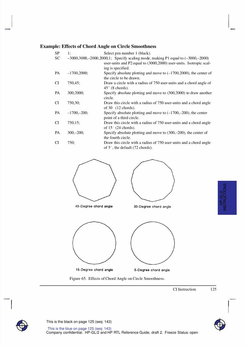
8/12/2019 HPGL2-RTL ReferenceGuide 5961-3526 540pages Sep96
http://slidepdf.com/reader/full/hpgl2-rtl-referenceguide-5961-3526-540pages-sep96 143/539
125
This is the black on page 125 (seq: 143)
Company confidential. HP-GL/2 and HP RTL Reference Guide, draft 2. Freeze Status: open
Example: Effects of Chord Angle on Circle Smoothness
SP 1; Select pen number 1 (black).
SC –3000,3000,–2000,2000,1; Specify scaling mode, making P1 equal to (–3000,–2000)
user-units and P2 equal to (3000,2000) user-units. Isotropic scal-
ing is specified.
PA –1700,2000; Specify absolute plotting and move to (–1700,2000), the center of
the circle to be drawn.
CI 750,45; Draw a circle with a radius of 750 user-units and a chord angle of
45 (8 chords).
PA 300,2000; Specify absolute plotting and move to (300,2000) to draw another
circle.
CI 750,30; Draw this circle with a radius of 750 user-units and a chord angle
of 30 (12 chords).
PA –1700,–200; Specify absolute plotting and move to (–1700,–200), the center
point of a third circle.
CI 750,15; Draw this circle with a radius of 750 user-units and a chord angleof 15 (24 chords).
PA 300,–200; Specify absolute plotting and move to (300,–200), the center of
the fourth circle.
CI 750; Draw this circle with a radius of 750 user-units and a chord angle
of 5, the default (72 chords).
Figure 65. Effects of Chord Angle on Circle Smoothness.
This is the blue on page 125 (seq: 143)
CI Instruction
I N S T R U C T I O N S
H P - G L / 2
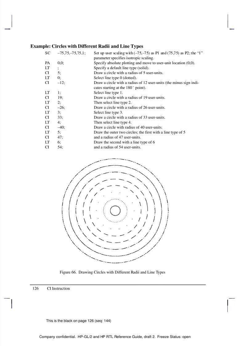
8/12/2019 HPGL2-RTL ReferenceGuide 5961-3526 540pages Sep96
http://slidepdf.com/reader/full/hpgl2-rtl-referenceguide-5961-3526-540pages-sep96 144/539
8/12/2019 HPGL2-RTL ReferenceGuide 5961-3526 540pages Sep96
http://slidepdf.com/reader/full/hpgl2-rtl-referenceguide-5961-3526-540pages-sep96 145/539
8/12/2019 HPGL2-RTL ReferenceGuide 5961-3526 540pages Sep96
http://slidepdf.com/reader/full/hpgl2-rtl-referenceguide-5961-3526-540pages-sep96 146/539
128
This is the black on page 128 (seq: 146)
Company confidential. HP-GL/2 and HP RTL Reference Guide, draft 2. Freeze Status: open
CP, Character Plot
Purpose
To move the pen the specified number of spaces and lines from the current pen location. UseCP to position a label for indenting, centering, and so on. It does not plot characters; that isnormally done by the LB (Label) instruction.
Syntax
CP spaces,lines[;]or
CP [;]
Á Á Á Á Á Á Á
Á Á Á Á Á Á Á
Parameter Á Á Á Á Á Á
Á Á Á Á Á Á
Format Á Á Á Á Á Á Á Á
Á Á Á Á Á Á Á Á
Functional Range Á Á Á Á Á Á Á Á
Á Á Á Á Á Á Á Á
Parameter Default
Á Á Á Á Á Á Á
Á Á Á Á Á Á Á
spaces Á Á Á Á Á Á
Á Á Á Á Á Á
clamped real Á Á Á Á Á Á Á Á
Á Á Á Á Á Á Á Á
–32 768 to 32 767 Á Á Á Á Á Á Á Á
Á Á Á Á Á Á Á Á
no default
Á Á Á Á Á Á Á
Á Á Á Á Á Á Á
linesÁ Á Á Á Á Á
Á Á Á Á Á Á
clamped realÁ Á Á Á Á Á Á Á
Á Á Á Á Á Á Á Á
–32 768 to 32 767Á Á Á Á Á Á Á Á
Á Á Á Á Á Á Á Á
no default
Group
This instruction is in the Character Group.
Use
The CP (Character Plot) instruction includes an automatic pen up. When the instruction is com-pleted, the original pen up/down status is restored.
CP moves the pen position in relation to the current position. CP is a movement instruction anddoes not affect the margin; to repeat the same movement for subsequent labels, you must issuenew CP instructions. (For information about the Carriage Return point, see Moving to the Car-riage Return Point on page 66.) For more information on spaces, lines, and the character cell,refer to Working with the Character Cell on page 58.
No Parameters: Performs a Carriage Return and Line Feed (moves one line down andreturns to the Carriage Return point).
spaces: Specifies the number of spaces the pen moves relative to the current pen location.Positive values specify the number of spaces the pen moves to the right of the current penposition; negative values specify the number of spaces the pen moves to the left. Right andleft are relative to the current label direction. The space width is uniquely defined for eachfont; use the ES (Extra Space) instruction to adjust the width.
Note: If you are using a proportionally-spaced font, the width of the Space () controlcode is used.
lines: Specifies the number of lines the pen moves relative to the current pen location.Positive values specify the number of lines the pen moves up from the current pen position;negative values specify the number of lines the pen moves down (a value of –1 is equiva-lent to a Line Feed). Up and down are relative to the current label direction. The Line
This is the blue on page 128 (seq: 146)
CP Instruction
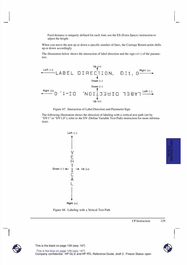
8/12/2019 HPGL2-RTL ReferenceGuide 5961-3526 540pages Sep96
http://slidepdf.com/reader/full/hpgl2-rtl-referenceguide-5961-3526-540pages-sep96 147/539
129
This is the black on page 129 (seq: 147)
Company confidential. HP-GL/2 and HP RTL Reference Guide, draft 2. Freeze Status: open
Feed distance is uniquely defined for each font; use the ES (Extra Space) instruction toadjust the height.
When you move the pen up or down a specific number of lines, the Carriage Return point shiftsup or down accordingly.
The illustration below shows the interaction of label direction and the sign (+/–) of the parame-ters.
Figure 67. Interaction of Label Direction and Parameter Sign
The following illustration shows the direction of labeling with a vertical text path (set by“DV1” or “DV1,0”); refer to the DV (Define Variable Text Path) instruction for more informa-tion).
Figure 68. Labeling with a Vertical Text Path
This is the blue on page 129 (seq: 147)
CP Instruction
I N S T R U C T I O N S
H P - G L / 2
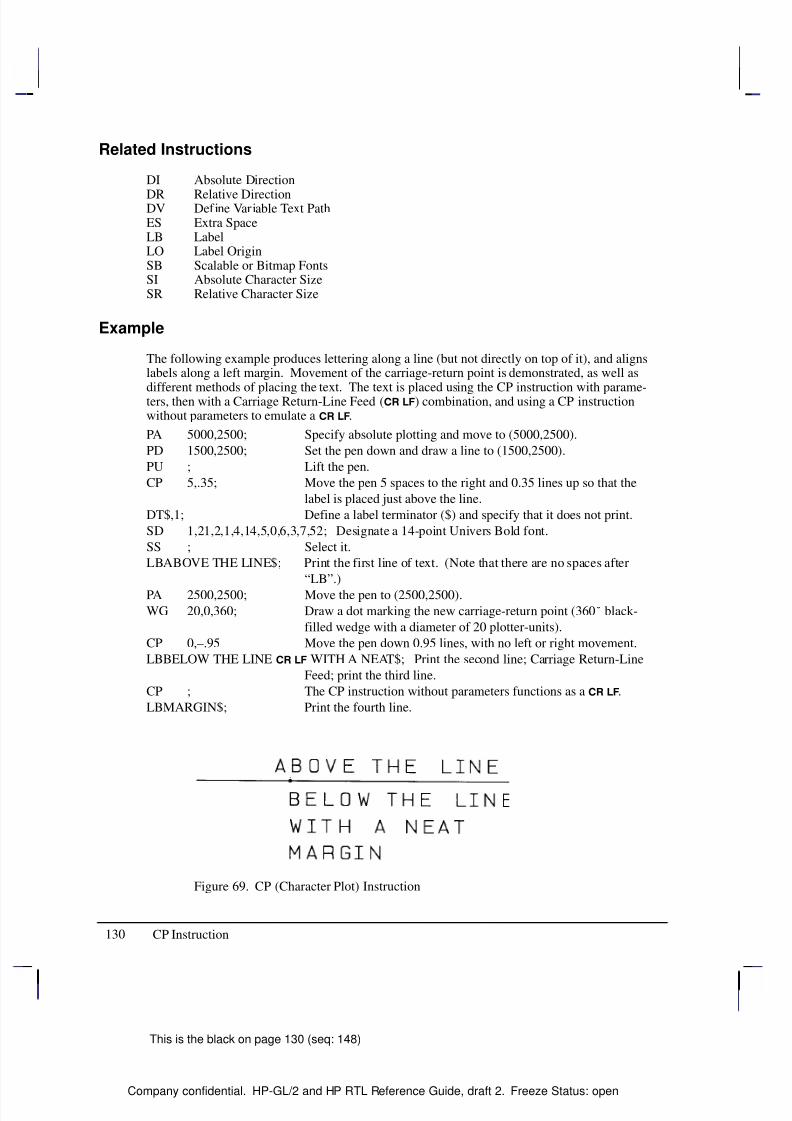
8/12/2019 HPGL2-RTL ReferenceGuide 5961-3526 540pages Sep96
http://slidepdf.com/reader/full/hpgl2-rtl-referenceguide-5961-3526-540pages-sep96 148/539
130
This is the black on page 130 (seq: 148)
Company confidential. HP-GL/2 and HP RTL Reference Guide, draft 2. Freeze Status: open
Related Instructions
DI Absolute Direction
DR Relative DirectionDV Define Variable Text PathES Extra SpaceLB LabelLO Label OriginSB Scalable or Bitmap FontsSI Absolute Character SizeSR Relative Character Size
Example
The following example produces lettering along a line (but not directly on top of it), and alignslabels along a left margin. Movement of the carriage-return point is demonstrated, as well as
different methods of placing the text. The text is placed using the CP instruction with parame-ters, then with a Carriage Return-Line Feed ( ) combination, and using a CP instructionwithout parameters to emulate a .
PA 5000,2500; Specify absolute plotting and move to (5000,2500).
PD 1500,2500; Set the pen down and draw a line to (1500,2500).
PU ; Lift the pen.
CP 5,.35; Move the pen 5 spaces to the right and 0.35 lines up so that the
label is placed just above the line.
DT$,1; Define a label terminator ($) and specify that it does not print.
SD 1,21,2,1,4,14,5,0,6,3,7,52; Designate a 14-point Univers Bold font.
SS ; Select it.
LBABOVE THE LINE$; Print the first line of text. (Note that there are no spaces after
“LB”.)
PA 2500,2500; Move the pen to (2500,2500).
WG 20,0,360; Draw a dot marking the new carriage-return point (360 black-
filled wedge with a diameter of 20 plotter-units).
CP 0,–.95 Move the pen down 0.95 lines, with no left or right movement.
LBBELOW THE LINE WITH A NEAT$; Print the second line; Carriage Return-Line
Feed; print the third line.
CP ; The CP instruction without parameters functions as a .
LBMARGIN$; Print the fourth line.
Figure 69. CP (Character Plot) Instruction
CP Instruction
8/12/2019 HPGL2-RTL ReferenceGuide 5961-3526 540pages Sep96
http://slidepdf.com/reader/full/hpgl2-rtl-referenceguide-5961-3526-540pages-sep96 149/539
131
This is the black on page 131 (seq: 149)
Company confidential. HP-GL/2 and HP RTL Reference Guide, draft 2. Freeze Status: open
CR, Set Color Range for Relative Color Data
Purpose
To establish the range for specifying primary color—for example, red/green/blue (RGB)—data.This instruction maps current pen colors to a numeric range while leaving the current palettecolors themselves unchanged. Pen plotters ignore (NOP) this instruction.
In an RGB color model, “primary1” or “p1” is red, “primary2” or “p2” is green, and “prima-ry3” or “p3” is blue.
Syntax
CR black-ref_p1,white-ref_p1,black-ref_p2,white-ref_p2,black-ref_p3,white-ref_p3[;]or
CR [;]
Á Á Á Á Á Á Á
Á Á Á Á Á Á Á
ParameterÁ Á Á Á Á Á Á
Á Á Á Á Á Á Á
FormatÁ Á Á Á Á Á Á Á
Á Á Á Á Á Á Á Á
Functional RangeÁ Á Á Á Á Á Á
Á Á Á Á Á Á Á
Parameter Default
Á Á Á Á Á Á Á
Á
Á Á Á Á Á Á
Á Á Á Á Á Á Á
black-ref (p1, p2, p3)
Á Á Á Á Á Á Á
Á
Á Á Á Á Á Á
Á Á Á Á Á Á Á
clamped real Á Á Á Á Á Á Á Á
Á
Á Á Á Á Á Á Á
Á Á Á Á Á Á Á Á
–32 768 to 32 767 Á Á Á Á Á Á Á
Á
Á Á Á Á Á Á
Á Á Á Á Á Á Á
0
Á Á Á Á Á Á Á
Á
Á Á Á Á Á Á
Á Á Á Á Á Á Á
white-ref
(p1, p2, p3)Á Á Á Á Á Á Á
Á
Á Á Á Á Á Á
Á Á Á Á Á Á Á
clamped realÁ Á Á Á Á Á Á Á
Á
Á Á Á Á Á Á Á
Á Á Á Á Á Á Á Á
–32 768 to 32 767Á Á Á Á Á Á Á
Á
Á Á Á Á Á Á
Á Á Á Á Á Á Á
255
Group
This instruction is in the Palette Extension.
Use
The black-reference for a primary color denotes a value assigned to the absence of that color.The white-reference denotes the value given to a fully saturated primary color. When you haveset the reference ranges, use the PC (Pen Color Assignment) instruction to define the colors of your pens.
No parameters: Defaults the black color references to 0 and the white references to 255.Equivalent to “CR0,255,0,255,0,255;”.
black-ref, white-ref (primary1, primary2, primary3): Sets the color to a range for eachprimary color. The first two parameters set the black- and white-references (respectively)for primary1 (or red), the second pair for primary2 (or green), and the final pair for prima-ry3 (or blue).
Using a black-reference of 0 and a white reference of 100 makes it easy to specify colors aspercentages of their fully saturated levels. Use the instruction “CR 0,100,0,100,0,100;”.
The reference values are reset to their defaults by the IN (Initialize) instruction.
In dual-context mode, CR can change the black and white references for palettes created by IN,BP, or *v#W. The new references are remembered when the PCL or HP RTL context isentered. This instruction is ignored if the current palette was created by *r#U or E.The equivalent PCL and HP RTL command is Configure Image Data (bytes 6 through 17).
This is the blue on page 131 (seq: 149)
CR Instruction
I N S T R U C T I O N S
H P - G L / 2
8/12/2019 HPGL2-RTL ReferenceGuide 5961-3526 540pages Sep96
http://slidepdf.com/reader/full/hpgl2-rtl-referenceguide-5961-3526-540pages-sep96 150/539
132
This is the black on page 132 (seq: 150)
Company confidential. HP-GL/2 and HP RTL Reference Guide, draft 2. Freeze Status: open
Related Instructions
NP Number of Pens
PC Pen Color AssignmentSV Screened VectorsTR Transparency Mode
Example
CR 0,63,0,63,0,63; This instruction sets the black references for each primary to 0,
and the white references to 63. The value for a medium blue
would be 0,0,31.
CR 4,63,0,127,0,31; This instruction sets the black reference to 4,0,0 and the white
reference to 63,127,31. In this case, medium blue would be
4,0,15.
Possible Error Conditions
Error Condition Error Number Printer or Plotter Response
One to five parameters 2 The instruction is ignored
Seven or more parameters 2 The extra parameters are ignored
The black reference value for anyprimary color is equal to its whitereference value
3 The instruction is ignored
CR Instruction
8/12/2019 HPGL2-RTL ReferenceGuide 5961-3526 540pages Sep96
http://slidepdf.com/reader/full/hpgl2-rtl-referenceguide-5961-3526-540pages-sep96 151/539
133
This is the black on page 133 (seq: 151)
Company confidential. HP-GL/2 and HP RTL Reference Guide, draft 2. Freeze Status: open
CT, Chord Tolerance Mode
Purpose
To specify whether the chord_angle parameter of the AA, AR, AT, CI, EW, RT, and WGinstructions is interpreted as a chord angle in degrees or as a deviation distance in current units.This instruction changes the way the number of chords is determined. It is defaulted by DF orIN.
Syntax
CT mode[;]or
CT[;]
Á Á Á Á Á Á Á
Á Á Á Á Á Á Á
ParameterÁ Á Á Á Á Á Á
Á Á Á Á Á Á Á
FormatÁ Á Á Á Á Á Á Á
Á Á Á Á Á Á Á Á
Functional RangeÁ Á Á Á Á Á Á
Á Á Á Á Á Á Á
Parameter DefaultÁ Á Á Á Á Á Á
Á
Á Á Á Á Á Á
Á Á Á Á Á Á Á
mode
Á Á Á Á Á Á Á
Á
Á Á Á Á Á Á
Á Á Á Á Á Á Á
clamped integer
Á Á Á Á Á Á Á Á
Á
Á Á Á Á Á Á Á
Á Á Á Á Á Á Á Á
0 or 1
Á Á Á Á Á Á Á
Á
Á Á Á Á Á Á
Á Á Á Á Á Á Á
0
Group
This instruction is in the Technical Graphics Extension.
Use
A plotted circle or arc actually consists of a series of straight line segments (chords) thatapproximate to arc segments. Increasing the number of chords increases the smoothness of thecircle or arc, but uses more of the device’s disk space. Chord tolerance is the acceptable devi-
ation from a smooth circle, and can be established as either a chord angle or a deviationdistance.
No parameters: equivalent to “CT0”.
mode: Specifies the type of chord tolerance, as follows:
0 Sets the chord tolerance mode to chord angle, which specifies, in degrees, themaximum angle created when lines from each end of the chord intersect the centerpoint of the circle. When chord tolerance is specified as a chord angle, a circle orarc will have the same number of chords, regardless of its size. See the left-handside of Figure 70.
1 Sets the chord tolerance mode to deviation distance, which specifies, in currentunits, the maximum distance between the chord and the arc segment it represents.
When you specify a deviation distance, the number of chords in a circle will varywith its size. See the right-hand side of Figure 70.
Note that when you change from the default mode of chord angle to deviation distance, thechord angle parameter of the arc instructions (AA, AR, AT, and RT), the wedge instructions(EW and WG), and the circle instruction (CI) will be interpreted as current units, not degrees.
This is the blue on page 133 (seq: 151)
CT Instruction
I N S T R U C T I O N S
H P - G L / 2
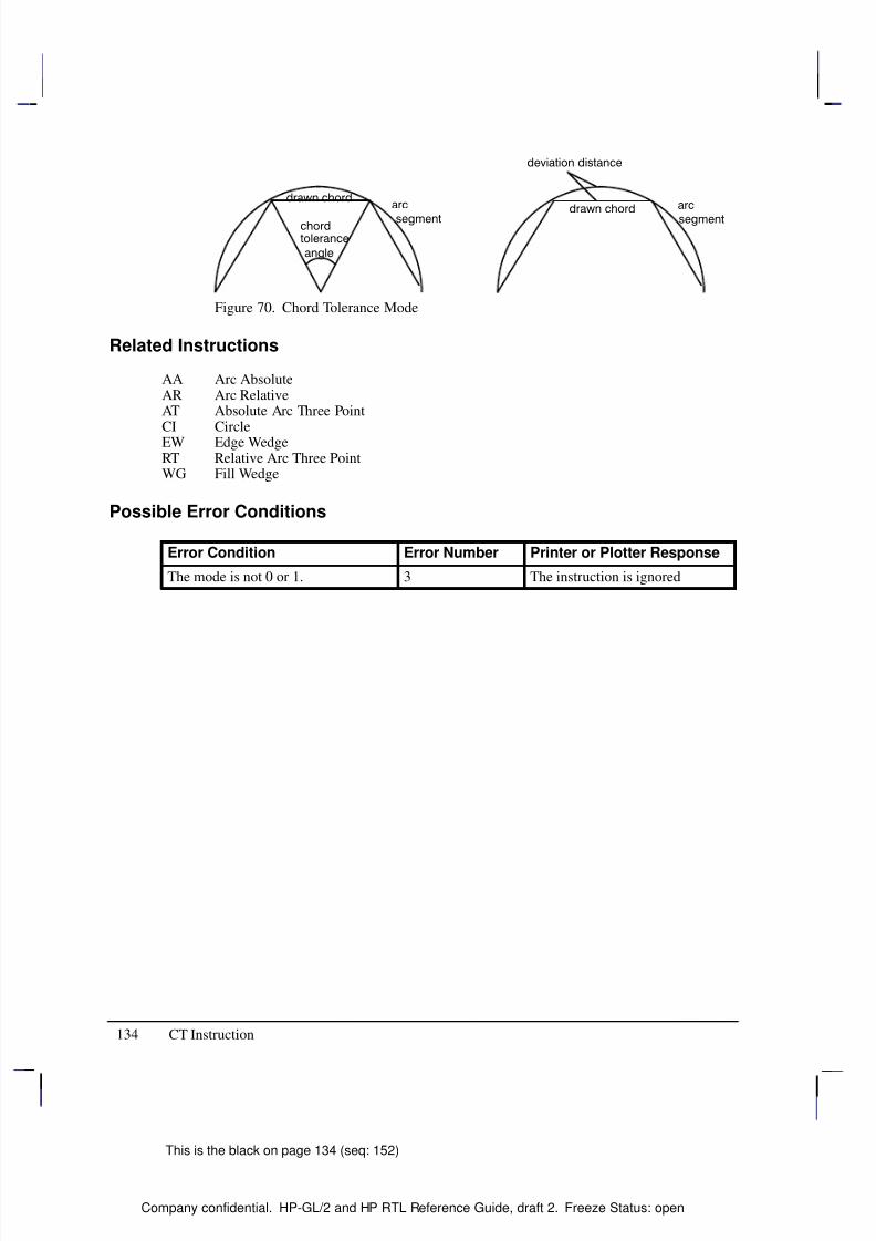
8/12/2019 HPGL2-RTL ReferenceGuide 5961-3526 540pages Sep96
http://slidepdf.com/reader/full/hpgl2-rtl-referenceguide-5961-3526-540pages-sep96 152/539
134
This is the black on page 134 (seq: 152)
Company confidential. HP-GL/2 and HP RTL Reference Guide, draft 2. Freeze Status: open
Figure 70. Chord Tolerance Mode
Related Instructions
AA Arc AbsoluteAR Arc RelativeAT Absolute Arc Three PointCI CircleEW Edge WedgeRT Relative Arc Three PointWG Fill Wedge
Possible Error Conditions
Error Condition Error Number Printer or Plotter Response
The mode is not 0 or 1. 3 The instruction is ignored
CT Instruction
8/12/2019 HPGL2-RTL ReferenceGuide 5961-3526 540pages Sep96
http://slidepdf.com/reader/full/hpgl2-rtl-referenceguide-5961-3526-540pages-sep96 153/539
135
This is the black on page 135 (seq: 153)
Company confidential. HP-GL/2 and HP RTL Reference Guide, draft 2. Freeze Status: open
DC, Digitize Clear
Purpose
To terminate digitize mode and reactivate automatic pen lift and storage. This instruction isonly supported by pen plotters.
Syntax
DC [;]
Group
This instruction is in the Digitizing Extension.
Use
If you are using an interrupt routine in a digitizing program to branch to another plotting func-tion, use DC to clear the digitize mode immediately after the branch.
When the device receives the DC instruction, it terminates digitize mode. It may also turn off any control-panel light (awaiting input of digitized point) and reactivate automatic pen lift.
Refer to The Digitizing Extension on page 89 and your device’s documentation for more in-formation.
Related Instructions
DP Digitize PointOD Output Digitized Point and Pen StatusOS Output Status
Possible Error Conditions
Error Condition Error Number Plotter Response
One or more parameters are specified 2 The parameters are ignored
This is the blue on page 135 (seq: 153)
DC Instruction
I N S T R U C T I O N S
H P - G L / 2
8/12/2019 HPGL2-RTL ReferenceGuide 5961-3526 540pages Sep96
http://slidepdf.com/reader/full/hpgl2-rtl-referenceguide-5961-3526-540pages-sep96 154/539
136
This is the black on page 136 (seq: 154)
Company confidential. HP-GL/2 and HP RTL Reference Guide, draft 2. Freeze Status: open
DF, Default Values
Purpose
To return the device’s HP-GL/2 settings to the factory default settings. Use the DF instructionto return the device to a known state while maintaining the current locations of P1 and P2, un-like the IN (Initialize) instruction. When you use DF at the beginning of a instructionsequence, graphics parameters such as character size, slant, or scaling are defaulted.
Syntax
DF [;]
Group
This instruction is in the Configuration and Status Group.
Use
The DF instruction resets the device to the following conditions:
FunctionEquivalentInstruction Default Condition
Anchor Corner AC; Anchor corner set to the origin of the hard-clip lim-its
Alternate Font Definition AD; Restore default (device-dependent) alternate font
characteristicsCharacter Fill Mode CF; Solid fill, no edging, uses the current pen
Absolute Direction DI; Absolute character direction parallel to X-axis
Define Label Terminator DT; and non-printing mode
Define Variable Text Path DV; Text printed in the +X-direction with Line Feed inthe –Y-direction
Extra Space ES; No extra space
Fill Type FT; Solid bidirectional fill (all previously specified pa-rameters for other fill types revert to their defaults)
Input Window IW; Hard-clip limits (printable area)
Line Attributes LA; Butt caps, mitered joins, and miter limit=5Label Origin LO1; Standard labeling starting at current location
Line Type LT; Solid line, relative mode, pattern length=4% of di-agonal distance from P1 to P2
Plotting Mode PA; Absolute plotting
Polygon Mode PM0;PM2; Polygon buffer cleared
Raster Fill RF; Solid raster fill in the current color for all patterns
This is the blue on page 136 (seq: 154)
DF Instruction
8/12/2019 HPGL2-RTL ReferenceGuide 5961-3526 540pages Sep96
http://slidepdf.com/reader/full/hpgl2-rtl-referenceguide-5961-3526-540pages-sep96 155/539
8/12/2019 HPGL2-RTL ReferenceGuide 5961-3526 540pages Sep96
http://slidepdf.com/reader/full/hpgl2-rtl-referenceguide-5961-3526-540pages-sep96 156/539
138
This is the black on page 138 (seq: 156)
Company confidential. HP-GL/2 and HP RTL Reference Guide, draft 2. Freeze Status: open
Using DF with the Palette Extension
The DF instruction also affects the following instructions:
FunctionEquivalentInstruction Default Condition
Set Color Range for Relative Color Data
CR0,255,0,255,0,255;
Range 0 through 255 for each primary color (red,green, blue)
Number of Pens NP; Device-dependent
Pen Color Assignment PC; Determined by the number of pens
Screened Vectors SV; No screening (solid vectors); defaults other pre-viously specified options
Transparency Mode TR1; Transparency mode on
Using DF in a Dual-Context Environment
The DF instruction also affects the following instructions:
FunctionEquivalentInstruction Default Condition
Anchor Corner AC; Places the anchor point at the origin of the currentcoordinate system
Input Window IW; Sets the user window equal to the hard-clip limits
Scalable or Bitmap Fonts SB0; Scalable fonts only
Using DF with the Advanced Text Extension
The DF instruction also affects the following instructions:
FunctionEquivalentInstruction Default Condition
Label Mode LM; 8-bit mode, row-number 0
Scalable or Bitmap Fonts SB0; Scalable fonts only
Related Instructions
BP Begin PlotIN InitializeLM Label ModeMC Merge ControlPP Pixel Placement
DF Instruction
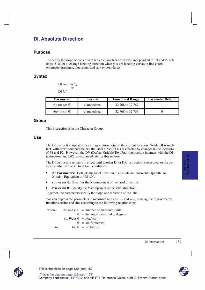
8/12/2019 HPGL2-RTL ReferenceGuide 5961-3526 540pages Sep96
http://slidepdf.com/reader/full/hpgl2-rtl-referenceguide-5961-3526-540pages-sep96 157/539
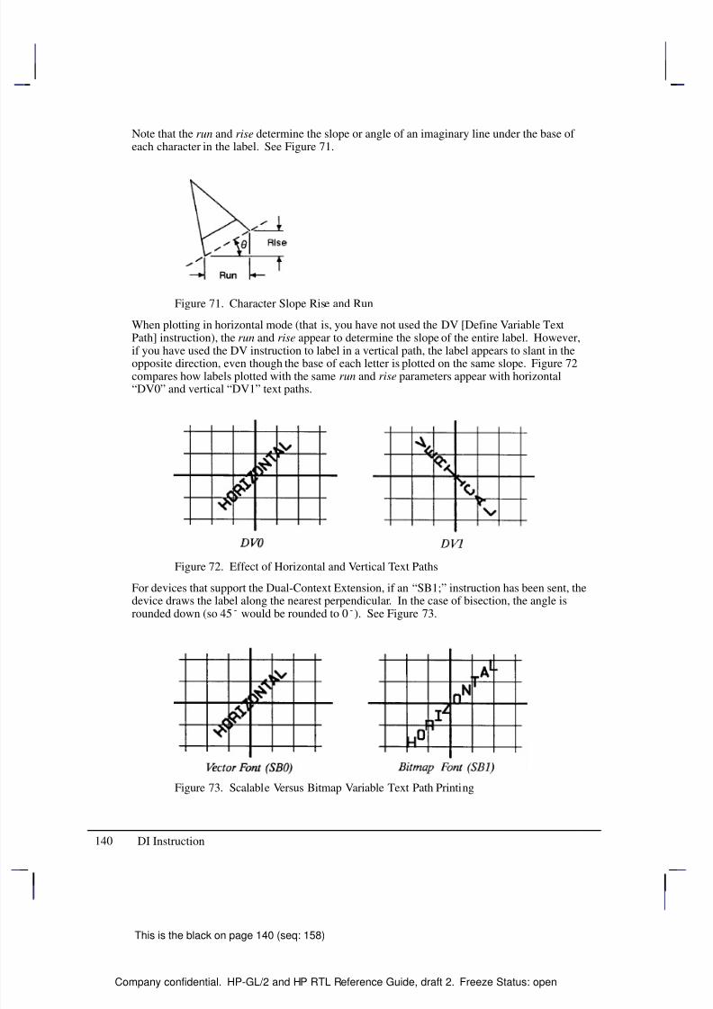
8/12/2019 HPGL2-RTL ReferenceGuide 5961-3526 540pages Sep96
http://slidepdf.com/reader/full/hpgl2-rtl-referenceguide-5961-3526-540pages-sep96 158/539
140
This is the black on page 140 (seq: 158)
Company confidential. HP-GL/2 and HP RTL Reference Guide, draft 2. Freeze Status: open
Note that the run and rise determine the slope or angle of an imaginary line under the base of each character in the label. See Figure 71.
Figure 71. Character Slope Rise and Run
When plotting in horizontal mode (that is, you have not used the DV [Define Variable TextPath] instruction), the run and rise appear to determine the slope of the entire label. However,
if you have used the DV instruction to label in a vertical path, the label appears to slant in theopposite direction, even though the base of each letter is plotted on the same slope. Figure 72compares how labels plotted with the same run and rise parameters appear with horizontal“DV0” and vertical “DV1” text paths.
Figure 72. Effect of Horizontal and Vertical Text Paths
For devices that support the Dual-Context Extension, if an “SB1;” instruction has been sent, thedevice draws the label along the nearest perpendicular. In the case of bisection, the angle isrounded down (so 45 would be rounded to 0). See Figure 73.
Figure 73. Scalable Versus Bitmap Variable Text Path Printing
DI Instruction
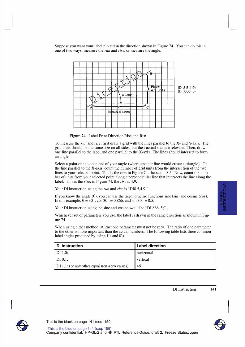
8/12/2019 HPGL2-RTL ReferenceGuide 5961-3526 540pages Sep96
http://slidepdf.com/reader/full/hpgl2-rtl-referenceguide-5961-3526-540pages-sep96 159/539
141
This is the black on page 141 (seq: 159)
Company confidential. HP-GL/2 and HP RTL Reference Guide, draft 2. Freeze Status: open
Suppose you want your label plotted in the direction shown in Figure 74. You can do this inone of two ways: measure the run and rise, or measure the angle.
Figure 74. Label Print Direction Rise and Run
To measure the run and rise, first draw a grid with the lines parallel to the X- and Y-axis. Thegrid units should be the same size on all sides, but their actual size is irrelevant. Then, drawone line parallel to the label and one parallel to the X-axis. The lines should intersect to forman angle.
Select a point on the open end of your angle (where another line would create a triangle). Onthe line parallel to the X-axis, count the number of grid units from the intersection of the twolines to your selected point. This is the run; in Figure 74, the run is 8.5. Now, count the num-ber of units from your selected point along a perpendicular line that intersects the line along the
label. This is the rise; in Figure 74, the rise is 4.9.Your DI instruction using the run and rise is “DI8.5,4.9;”.
If you know the angle (), you can use the trigonometric functions sine (sin) and cosine (cos).In this example, = 30, cos 30 = 0.866, and sin 30 = 0.5.
Your DI instruction using the sine and cosine would be “DI.866,.5;”.
Whichever set of parameters you use, the label is drawn in the same direction as shown in Fig-ure 74.
When using either method, at least one parameter must not be zero. The ratio of one parameterto the other is more important than the actual numbers. The following table lists three commonlabel angles produced by using 1’s and 0’s.
DI instruction Label direction
DI 1,0; horizontal
DI 0,1; vertical
DI 1,1; (or any other equal non-zero values) 45
This is the blue on page 141 (seq: 159)
DI Instruction
I N S T R U C T I O N S
H P - G L / 2
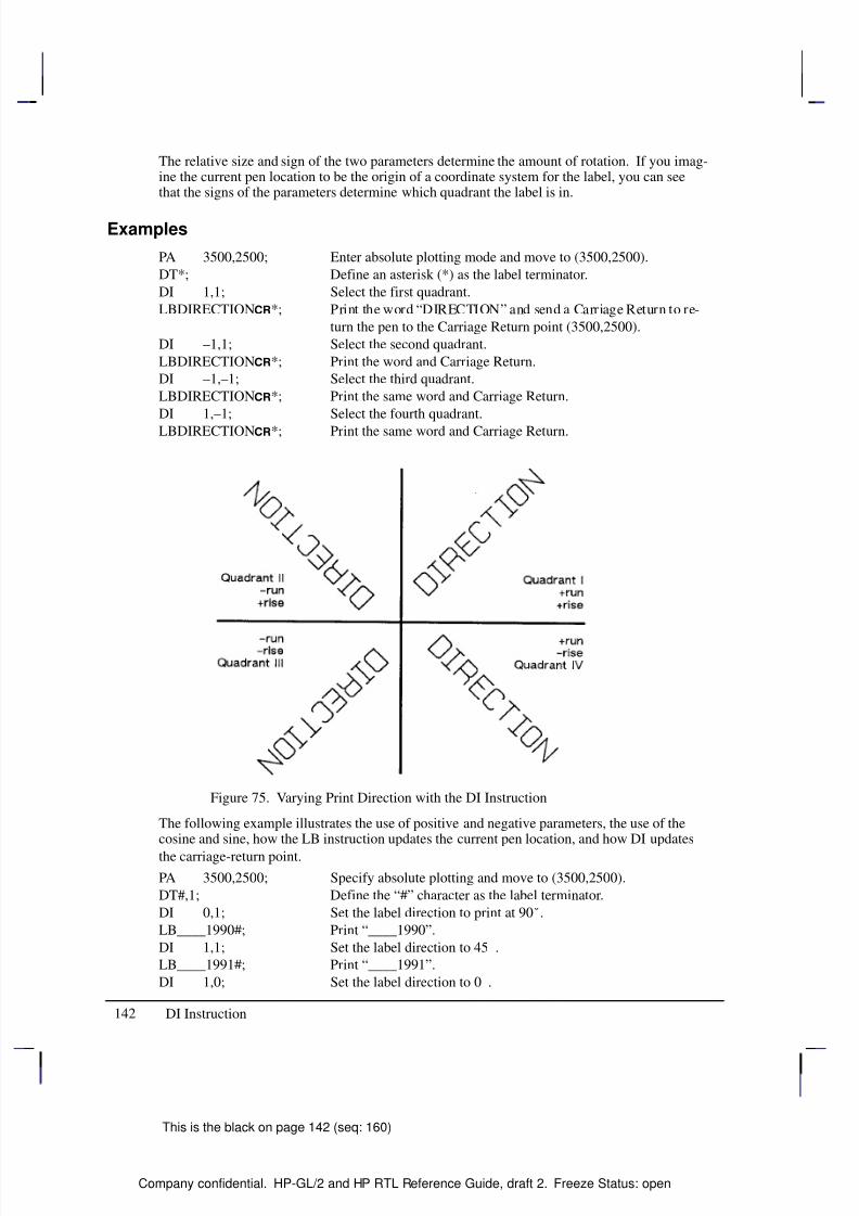
8/12/2019 HPGL2-RTL ReferenceGuide 5961-3526 540pages Sep96
http://slidepdf.com/reader/full/hpgl2-rtl-referenceguide-5961-3526-540pages-sep96 160/539
142
This is the black on page 142 (seq: 160)
Company confidential. HP-GL/2 and HP RTL Reference Guide, draft 2. Freeze Status: open
The relative size and sign of the two parameters determine the amount of rotation. If you imag-ine the current pen location to be the origin of a coordinate system for the label, you can seethat the signs of the parameters determine which quadrant the label is in.
Examples
PA 3500,2500; Enter absolute plotting mode and move to (3500,2500).
DT*; Define an asterisk (*) as the label terminator.
DI 1,1; Select the first quadrant.
LBDIRECTION*; Print the word “DIRECTION” and send a Carriage Return to re-
turn the pen to the Carriage Return point (3500,2500).
DI –1,1; Select the second quadrant.
LBDIRECTION*; Print the word and Carriage Return.
DI –1,–1; Select the third quadrant.
LBDIRECTION*; Print the same word and Carriage Return.
DI 1,–1; Select the fourth quadrant.
LBDIRECTION*; Print the same word and Carriage Return.
Figure 75. Varying Print Direction with the DI Instruction
The following example illustrates the use of positive and negative parameters, the use of thecosine and sine, how the LB instruction updates the current pen location, and how DI updates
the carriage-return point.
PA 3500,2500; Specify absolute plotting and move to (3500,2500).
DT#,1; Define the “#” character as the label terminator.
DI 0,1; Set the label direction to print at 90.
LB____1990#; Print “____1990”.
DI 1,1; Set the label direction to 45.
LB____1991#; Print “____1991”.
DI 1,0; Set the label direction to 0.
DI Instruction
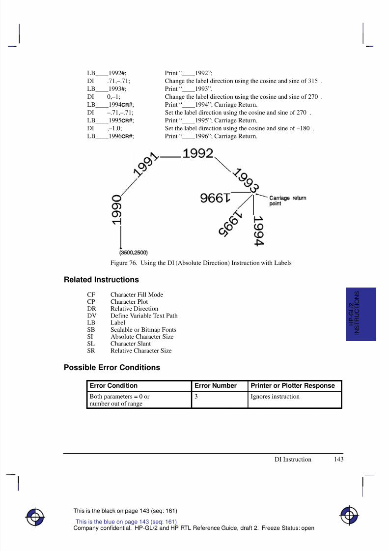
8/12/2019 HPGL2-RTL ReferenceGuide 5961-3526 540pages Sep96
http://slidepdf.com/reader/full/hpgl2-rtl-referenceguide-5961-3526-540pages-sep96 161/539
143
This is the black on page 143 (seq: 161)
Company confidential. HP-GL/2 and HP RTL Reference Guide, draft 2. Freeze Status: open
LB____1992#; Print “____1992”;
DI .71,–.71; Change the label direction using the cosine and sine of 315.
LB____1993#; Print “____1993”.
DI 0,–1; Change the label direction using the cosine and sine of 270.LB____1994#; Print “____1994”; Carriage Return.
DI –.71,–.71; Set the label direction using the cosine and sine of 270.
LB____1995#; Print “____1995”; Carriage Return.
DI ,–1,0; Set the label direction using the cosine and sine of –180.
LB____1996#; Print “____1996”; Carriage Return.
Figure 76. Using the DI (Absolute Direction) Instruction with Labels
Related Instructions
CF Character Fill ModeCP Character PlotDR Relative DirectionDV Define Variable Text PathLB LabelSB Scalable or Bitmap FontsSI Absolute Character SizeSL Character SlantSR Relative Character Size
Possible Error Conditions
Error Condition Error Number Printer or Plotter ResponseBoth parameters = 0 ornumber out of range
3 Ignores instruction
This is the blue on page 143 (seq: 161)
DI Instruction
I N S T R U C T I O N S
H P - G L / 2
8/12/2019 HPGL2-RTL ReferenceGuide 5961-3526 540pages Sep96
http://slidepdf.com/reader/full/hpgl2-rtl-referenceguide-5961-3526-540pages-sep96 162/539
8/12/2019 HPGL2-RTL ReferenceGuide 5961-3526 540pages Sep96
http://slidepdf.com/reader/full/hpgl2-rtl-referenceguide-5961-3526-540pages-sep96 163/539
8/12/2019 HPGL2-RTL ReferenceGuide 5961-3526 540pages Sep96
http://slidepdf.com/reader/full/hpgl2-rtl-referenceguide-5961-3526-540pages-sep96 164/539
146
This is the black on page 146 (seq: 164)
Company confidential. HP-GL/2 and HP RTL Reference Guide, draft 2. Freeze Status: open
Related Instructions
AD Alternate Font Definition
LB LabelSA Select Alternate FontSD Standard Font DefinitionSS Select Standard Font
Possible Error Conditions
Error Condition Error Number Printer or Plotter Response
Y-coordinate missing 2 Ignores instruction
Up-flag follows X-coordinate 2 Ignores instruction
Parameter out of range 3 Ignores instruction
X,Y data out of range 3 Ignores instruction
Buffer overflow 7 Ignores instruction
Example
This sequence of instructions uses a character that is downloaded:
AD 1,531,3,3 Alternate Font Definition: character set 531, pitch 3 characters per
inch.
DL 65, 10,0, 10,30, 28,30, 28,24 Download Character number 65 (“A”), starting at
(10,0), draw to (10,30), to (28,30), and finally to (28,24).
PU Pen Up.
PA 300,300 Plot Absolute, moves the pen to (300,300).LBThe symbol for gamma is A Label, using the shift-out () character, decimal code
14, to switch to the alternate font, and the end-of-text ( ) char-
acter, decimal 3, to terminate the text.
(An alternative sequence, using the SA (Select Alternate Font)
instruction, would be:
LBThe symbol for gamma is SALBA
but is four bytes longer.)
This is the result:
The symbol for gamma is
Figure 77 shows how the gamma symbol fits in its character grid.
DL Instruction
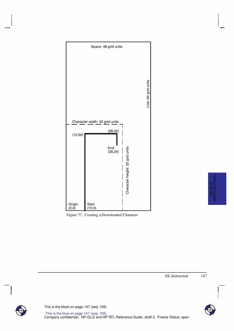
8/12/2019 HPGL2-RTL ReferenceGuide 5961-3526 540pages Sep96
http://slidepdf.com/reader/full/hpgl2-rtl-referenceguide-5961-3526-540pages-sep96 165/539
147
This is the black on page 147 (seq: 165)
Company confidential. HP-GL/2 and HP RTL Reference Guide, draft 2. Freeze Status: open
Figure 77. Creating a Downloaded Character
This is the blue on page 147 (seq: 165)
DL Instruction
I N S T R U C T I O N S
H P - G L / 2
8/12/2019 HPGL2-RTL ReferenceGuide 5961-3526 540pages Sep96
http://slidepdf.com/reader/full/hpgl2-rtl-referenceguide-5961-3526-540pages-sep96 166/539
148
This is the black on page 148 (seq: 166)
Company confidential. HP-GL/2 and HP RTL Reference Guide, draft 2. Freeze Status: open
DP, Digitize Point
Purpose
To enable digitize mode and suppress automatic pen lift and storage. In digitize mode, youhave full control of the pen holder. The device remains in digitize mode until a point is enteredusing a front-panel control, or digitize mode is terminated by the DC (Digitize Clear) instruc-tion.
Syntax
DP [;]
Group
This instruction is in the Digitizing Extension.
Use
This instruction suppresses any automatic pen storage and lift that may be implemented in theplotter.
This instruction may turn on a control-panel light to indicate that it is waiting for you to enter apoint. Use the control-panel cursor-buttons to move the digitizing sight to the appropriate loca-tion, lower the sight, and then press the appropriate control-panel button (usually the Enterbutton).
Entering a point sets bit position 2 of the OS instruction status byte to indicate that a digitized
point is available for output when requested by the OD instruction. Use the OD instruction toretrieve the X,Y coordinates of the point and the pen state (up or down). Then you can displaythese coordinates on your computer screen or write them to a file.
See The Digitizing Extension on page 89 for more information.
Related Instructions
DC Digitize ClearOD Output Digitized Point and Pen StatusOS Output Status
Possible Error Conditions
Error Condition Error Number Plotter Response
One or more parameters are specified 2 The parameters are ignored
This is the blue on page 148 (seq: 166)
DP Instruction
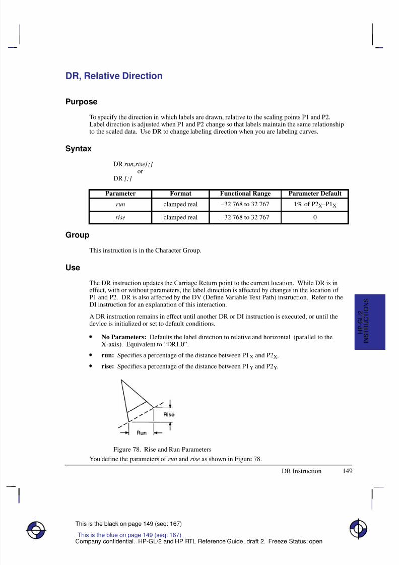
8/12/2019 HPGL2-RTL ReferenceGuide 5961-3526 540pages Sep96
http://slidepdf.com/reader/full/hpgl2-rtl-referenceguide-5961-3526-540pages-sep96 167/539
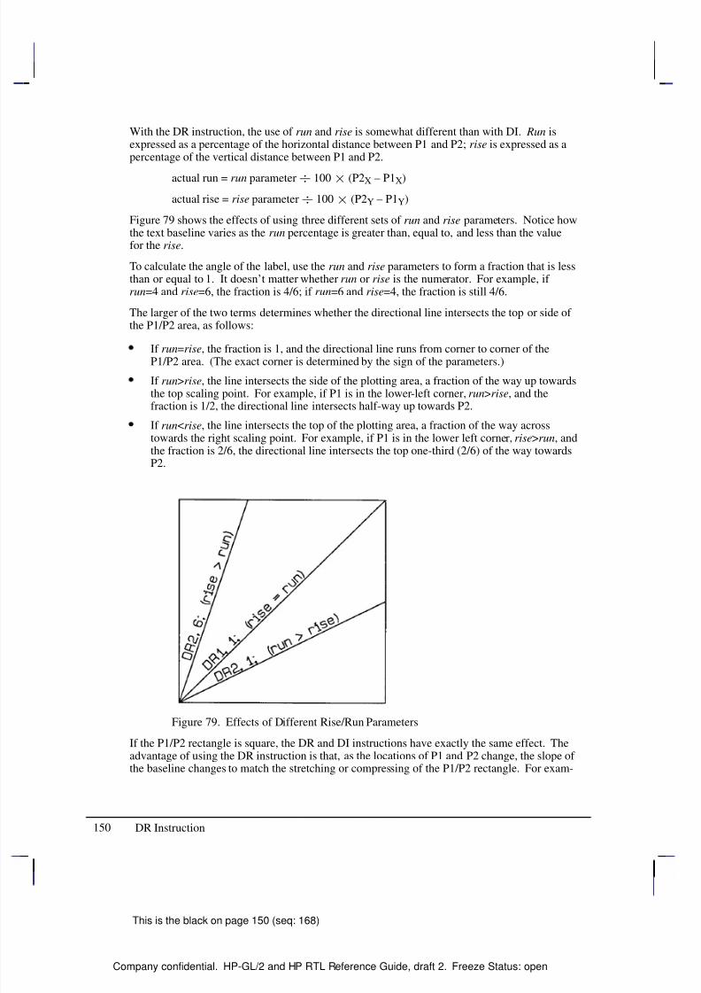
8/12/2019 HPGL2-RTL ReferenceGuide 5961-3526 540pages Sep96
http://slidepdf.com/reader/full/hpgl2-rtl-referenceguide-5961-3526-540pages-sep96 168/539
150
This is the black on page 150 (seq: 168)
Company confidential. HP-GL/2 and HP RTL Reference Guide, draft 2. Freeze Status: open
With the DR instruction, the use of run and rise is somewhat different than with DI. Run isexpressed as a percentage of the horizontal distance between P1 and P2; rise is expressed as apercentage of the vertical distance between P1 and P2.
actual run = run parameter 100 (P2X – P1X)
actual rise = rise parameter 100 (P2Y – P1Y)
Figure 79 shows the effects of using three different sets of run and rise parameters. Notice howthe text baseline varies as the run percentage is greater than, equal to, and less than the valuefor the rise.
To calculate the angle of the label, use the run and rise parameters to form a fraction that is lessthan or equal to 1. It doesn’t matter whether run or rise is the numerator. For example, if run=4 and rise=6, the fraction is 4/6; if run=6 and rise=4, the fraction is still 4/6.
The larger of the two terms determines whether the directional line intersects the top or side of the P1/P2 area, as follows:
If run=rise, the fraction is 1, and the directional line runs from corner to corner of theP1/P2 area. (The exact corner is determined by the sign of the parameters.)
If run>rise, the line intersects the side of the plotting area, a fraction of the way up towardsthe top scaling point. For example, if P1 is in the lower-left corner, run>rise, and thefraction is 1/2, the directional line intersects half-way up towards P2.
If run<rise, the line intersects the top of the plotting area, a fraction of the way acrosstowards the right scaling point. For example, if P1 is in the lower left corner, rise>run, andthe fraction is 2/6, the directional line intersects the top one-third (2/6) of the way towardsP2.
Figure 79. Effects of Different Rise/Run Parameters
If the P1/P2 rectangle is square, the DR and DI instructions have exactly the same effect. Theadvantage of using the DR instruction is that, as the locations of P1 and P2 change, the slope of the baseline changes to match the stretching or compressing of the P1/P2 rectangle. For exam-
DR Instruction
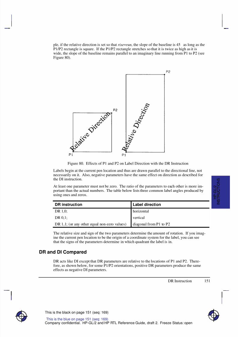
8/12/2019 HPGL2-RTL ReferenceGuide 5961-3526 540pages Sep96
http://slidepdf.com/reader/full/hpgl2-rtl-referenceguide-5961-3526-540pages-sep96 169/539
151
This is the black on page 151 (seq: 169)
Company confidential. HP-GL/2 and HP RTL Reference Guide, draft 2. Freeze Status: open
ple, if the relative direction is set so that rise=run, the slope of the baseline is 45 as long as theP1/P2 rectangle is square. If the P1/P2 rectangle stretches so that it is twice as high as it iswide, the slope of the baseline remains parallel to an imaginary line running from P1 to P2 (see
Figure 80).
Figure 80. Effects of P1 and P2 on Label Direction with the DR Instruction
Labels begin at the current pen location and thus are drawn parallel to the directional line, notnecessarily on it. Also, negative parameters have the same effect on direction as described forthe DI instruction.
At least one parameter must not be zero. The ratio of the parameters to each other is more im-portant than the actual numbers. The table below lists three common label angles produced byusing ones and zeros.
DR instruction Label direction
DR 1,0; horizontal
DR 0,1; vertical
DR 1,1; (or any other equal non-zero values) diagonal from P1 to P2
The relative size and sign of the two parameters determine the amount of rotation. If you imag-ine the current pen location to be the origin of a coordinate system for the label, you can seethat the signs of the parameters determine in which quadrant the label is in.
DR and DI Compared
DR acts like DI except that DR parameters are relative to the locations of P1 and P2. There-fore, as shown below, for some P1/P2 orientations, positive DR parameters produce the sameeffects as negative DI parameters.
This is the blue on page 151 (seq: 169)
DR Instruction
I N S T R U C T I O N S
H P - G L / 2
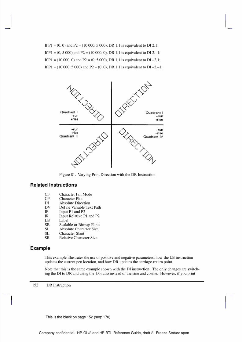
8/12/2019 HPGL2-RTL ReferenceGuide 5961-3526 540pages Sep96
http://slidepdf.com/reader/full/hpgl2-rtl-referenceguide-5961-3526-540pages-sep96 170/539
152
This is the black on page 152 (seq: 170)
Company confidential. HP-GL/2 and HP RTL Reference Guide, draft 2. Freeze Status: open
If P1 = (0, 0) and P2 = (10 000, 5 000), DR 1,1 is equivalent to DI 2,1;
If P1 = (0, 5 000) and P2 = (10 000, 0), DR 1,1 is equivalent to DI 2,–1;
If P1 = (10 000, 0) and P2 = (0, 5 000), DR 1,1 is equivalent to DI –2,1;
If P1 = (10 000, 5 000) and P2 = (0, 0), DR 1,1 is equivalent to DI –2,–1;
Figure 81. Varying Print Direction with the DR Instruction
Related Instructions
CF Character Fill ModeCP Character PlotDI Absolute DirectionDV Define Variable Text PathIP Input P1 and P2IR Input Relative P1 and P2LB LabelSB Scalable or Bitmap FontsSI Absolute Character SizeSL Character Slant
SR Relative Character Size
Example
This example illustrates the use of positive and negative parameters, how the LB instructionupdates the current pen location, and how DR updates the carriage-return point.
Note that this is the same example shown with the DI instruction. The only changes are switch-ing the DI to DR and using the 1:0 ratio instead of the sine and cosine. However, if you print
DR Instruction
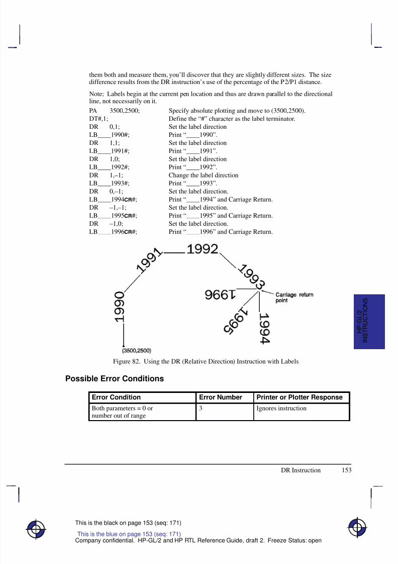
8/12/2019 HPGL2-RTL ReferenceGuide 5961-3526 540pages Sep96
http://slidepdf.com/reader/full/hpgl2-rtl-referenceguide-5961-3526-540pages-sep96 171/539
153
This is the black on page 153 (seq: 171)
Company confidential. HP-GL/2 and HP RTL Reference Guide, draft 2. Freeze Status: open
them both and measure them, you’ll discover that they are slightly different sizes. The sizedifference results from the DR instruction’s use of the percentage of the P2/P1 distance.
Note; Labels begin at the current pen location and thus are drawn parallel to the directionalline, not necessarily on it.
PA 3500,2500; Specify absolute plotting and move to (3500,2500).
DT#,1; Define the “#” character as the label terminator.
DR 0,1; Set the label direction
LB____1990#; Print “____1990”.
DR 1,1; Set the label direction
LB____1991#; Print “____1991”.
DR 1,0; Set the label direction
LB____1992#; Print “____1992”.
DR 1,–1; Change the label direction
LB____1993#; Print “____1993”.
DR 0,–1; Set the label direction.
LB____1994#; Print “____1994” and Carriage Return.DR –1,–1; Set the label direction.
LB____1995#; Print “____1995” and Carriage Return.
DR –1,0; Set the label direction.
LB____1996#; Print “____1996” and Carriage Return.
Figure 82. Using the DR (Relative Direction) Instruction with Labels
Possible Error Conditions
Error Condition Error Number Printer or Plotter Response
Both parameters = 0 ornumber out of range
3 Ignores instruction
This is the blue on page 153 (seq: 171)
DR Instruction
I N S T R U C T I O N S
H P - G L / 2
8/12/2019 HPGL2-RTL ReferenceGuide 5961-3526 540pages Sep96
http://slidepdf.com/reader/full/hpgl2-rtl-referenceguide-5961-3526-540pages-sep96 172/539
154
This is the black on page 154 (seq: 172)
Company confidential. HP-GL/2 and HP RTL Reference Guide, draft 2. Freeze Status: open
DT, Define Label Terminator
Purpose
To specify the character to be used as the label terminator and whether it is printed. Use DT todefine a new label terminator if you need a different one or if your computer cannot use thedefault ( , decimal code 3).
Syntax
DT label_terminator[,mode];or
DT ;
You must use a terminator (;) with this instruction.
Á Á Á Á Á Á Á
Á Á Á Á Á Á Á
Parameter Á Á Á Á Á Á
Á Á Á Á Á Á
Format Á Á Á Á Á Á Á Á
Á Á Á Á Á Á Á Á
Functional Range Á Á Á Á Á Á Á Á
Á Á Á Á Á Á Á Á
Parameter DefaultÁ Á Á Á Á Á Á
Á Á Á Á Á Á Á
Á Á Á Á Á Á Á
Á Á Á Á Á Á Á
label_terminator Á Á Á Á Á Á
Á Á Á Á Á Á
Á
Á Á Á Á Á
Á Á Á Á Á Á
labelÁ Á Á Á Á Á Á Á
Á Á Á Á Á Á Á Á
Á
Á Á Á Á Á Á Á
Á Á Á Á Á Á Á Á
any character except, , , and ;
(decimal codes 0, 5, 27,and 59 respectively)*
Á Á Á Á Á Á Á Á
Á Á Á Á Á Á Á Á
Á
Á Á Á Á Á Á Á
Á Á Á Á Á Á Á Á
(decimal code 3)
Á Á Á Á Á Á Á
Á Á Á Á Á Á Á
Á Á Á Á Á Á Á
mode
Á Á Á Á Á Á
Á
Á Á Á Á Á
Á Á Á Á Á Á
clamped integer
Á Á Á Á Á Á Á Á
Á
Á Á Á Á Á Á Á
Á Á Á Á Á Á Á Á
0 or 1
Á Á Á Á Á Á Á Á
Á
Á Á Á Á Á Á Á
Á Á Á Á Á Á Á Á
1 (non-printing)
* If you specify a label_terminator of decimal code 0, 5, or 27, the device ignores theinstruction; the terminator remains unchanged.
Group
This instruction is in the Character Group.
Use
The character immediately following DT is interpreted to be the new label terminator. Youmust terminate all LB (Label) instructions following a DT instruction with the specified labelterminator.
No Parameter: Defaults the label terminator to (not a semicolon) and the mode tonon-printing. Equivalent to “DT ,1;”.
label_terminator: Specifies the label terminator as the character immediately followingthe DT mnemonic. (If you use a space between the mnemonic and your intended la-
bel_terminator parameter, the space becomes the label terminator; that is why theexamples of DT in this book show no space after the instruction mnemonic, unlike mostother instructions.)
mode: Specifies whether the label terminator is printed.
0 The label terminator prints if it is a printable character and performs its function if it is a control code.
1 The label terminator does not print if it is a printing character and does not per-form its function if it is a control code. (This is the default.)
This is the blue on page 154 (seq: 172)
DT Instruction
8/12/2019 HPGL2-RTL ReferenceGuide 5961-3526 540pages Sep96
http://slidepdf.com/reader/full/hpgl2-rtl-referenceguide-5961-3526-540pages-sep96 173/539
155
This is the black on page 155 (seq: 173)
Company confidential. HP-GL/2 and HP RTL Reference Guide, draft 2. Freeze Status: open
In 16-bit mode, the label terminator and all 8-bit control codes of an LB instruction must have afirst byte set to 0. For example, and escape character (, ASCII 27) would be sent as a 0followed by a 27. The exception is E in dual-context devices, which is parsed and executed
regardless of byte boundaries with the LB and SM instructions.If you are using LM to label a 16-bit character set, you need to switch back to 8-bit mode forthe terminator. DT works with 8-bit terminators only; it does not work with 16-bit characters.
A DT instruction remains in effect until another DT instruction is executed, or the device isinitialized or set to default conditions.
Related Instructions
LB LabelTD Transparent Data
Examples
The following instructions show how to define and print using a non-printing label terminator:
DT#; Define “#” as the label terminator.
LBThe label terminator WILL NOT print.#; This instruction would print as:
The label terminator WILL NOT print.
This example shows how to define and use a printable label terminator:
DT#,0; Define “#” as the label terminator.
LBThe label terminator WILL print.#; This instruction would print as:
The label terminator WILL print.#
This is the blue on page 155 (seq: 173)
DT Instruction
I N S T R U C T I O N S
H P - G L / 2
8/12/2019 HPGL2-RTL ReferenceGuide 5961-3526 540pages Sep96
http://slidepdf.com/reader/full/hpgl2-rtl-referenceguide-5961-3526-540pages-sep96 174/539
156
This is the black on page 156 (seq: 174)
Company confidential. HP-GL/2 and HP RTL Reference Guide, draft 2. Freeze Status: open
DV, Define Variable Text Path
Purpose
To specify the text path for subsequent labels and the direction of Line Feeds as either right,left, up, or down. Use DV to “stack” characters in a column.
Syntax
DV path[,line][;]or
DV [;]
Á Á Á Á Á Á Á
Á Á Á Á Á Á Á
ParameterÁ Á Á Á Á Á
Á Á Á Á Á Á
FormatÁ Á Á Á Á Á Á Á
Á Á Á Á Á Á Á Á
Functional RangeÁ Á Á Á Á Á Á Á
Á Á Á Á Á Á Á Á
Parameter DefaultÁ Á Á Á Á Á Á
Á Á Á Á Á Á Á
path
Á Á Á Á Á Á
Á Á Á Á Á Á
clamped integer
Á Á Á Á Á Á Á Á
Á Á Á Á Á Á Á Á
0, 1, 2, or 3
Á Á Á Á Á Á Á Á
Á Á Á Á Á Á Á Á
0 (horizontal)Á Á Á Á Á Á Á
Á Á Á Á Á Á Á
Á Á Á Á Á Á Á
lineÁ Á Á Á Á Á
Á
Á Á Á Á Á
Á Á Á Á Á Á
clamped integerÁ Á Á Á Á Á Á Á
Á
Á Á Á Á Á Á Á
Á Á Á Á Á Á Á Á
0 or 1Á Á Á Á Á Á Á Á
Á
Á Á Á Á Á Á Á
Á Á Á Á Á Á Á Á
0 (normal Line Feed)
Group
This instruction is in the Character Group.
Use
The DV instruction determines the text path, the direction that the current location moves aftereach character is drawn and the direction that the carriage-return point moves when a Line Feedis included in the label string. It alters the relative positions of successive characters in a label,
but does not change the orientation of individual characters. It updates the carriage-return pointto the current pen location.
No Parameter: Defaults the text path to horizontal (not stacked) with normal Line Feed.Equivalent to “DV0,0”.
path: Specifies the location of each character with respect to the preceding character,relative to the labeling direction defined by the DI or DR instructions. The text path set byDV is not affected by changes in P1 and P2.
0 0 (in the +X-direction). Within a label, each character begins to the right of theprevious character. This is a horizontal text path (unless altered by DI or DR).
1 –90 (in the –Y-direction). Within a label, each character begins below the pre-vious character. This is a vertical text path (unless altered by DI or DR).
2 –180 (in the –X-direction). Within a label, each character begins to the left of the previous character. This is a horizontal text path (unless altered by DI or DR).
3 –270 (in the +Y-direction). Within a label, each character begins above the pre-vious character. This is a vertical text path (unless altered by DI or DR).
For PCL printers, the path values represent paths that are to the right (0), down (1), left (2),and up (3).
Figure 83 shows the four text paths. +X is to the right; +Y is up.
This is the blue on page 156 (seq: 174)
DV Instruction
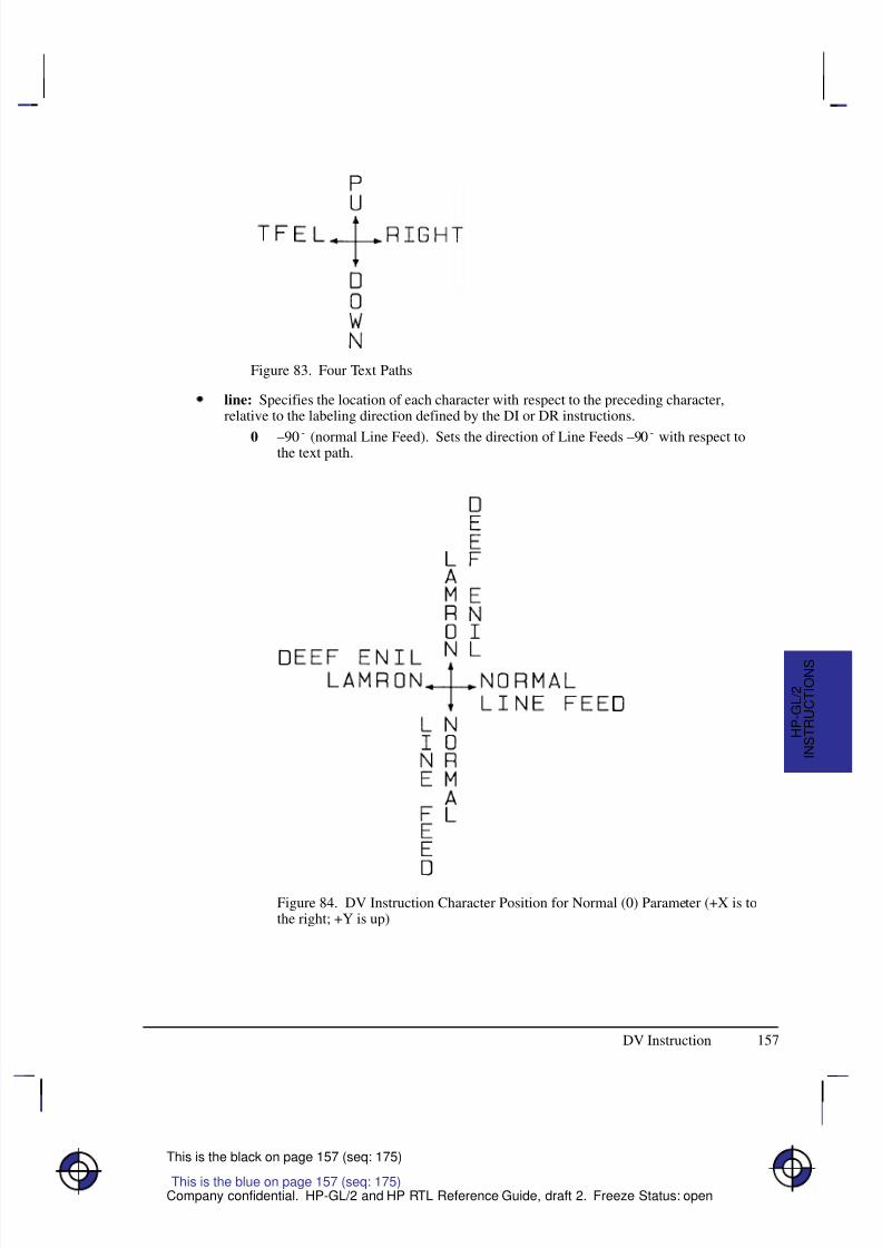
8/12/2019 HPGL2-RTL ReferenceGuide 5961-3526 540pages Sep96
http://slidepdf.com/reader/full/hpgl2-rtl-referenceguide-5961-3526-540pages-sep96 175/539
157
This is the black on page 157 (seq: 175)
Company confidential. HP-GL/2 and HP RTL Reference Guide, draft 2. Freeze Status: open
Figure 83. Four Text Paths
line: Specifies the location of each character with respect to the preceding character,relative to the labeling direction defined by the DI or DR instructions.
0 –90 (normal Line Feed). Sets the direction of Line Feeds –90 with respect tothe text path.
Figure 84. DV Instruction Character Position for Normal (0) Parameter (+X is tothe right; +Y is up)
This is the blue on page 157 (seq: 175)
DV Instruction
I N S T R U C T I O N S
H P - G L / 2
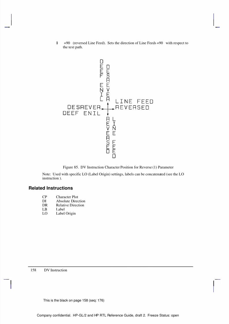
8/12/2019 HPGL2-RTL ReferenceGuide 5961-3526 540pages Sep96
http://slidepdf.com/reader/full/hpgl2-rtl-referenceguide-5961-3526-540pages-sep96 176/539
158
This is the black on page 158 (seq: 176)
Company confidential. HP-GL/2 and HP RTL Reference Guide, draft 2. Freeze Status: open
1 +90 (reversed Line Feed). Sets the direction of Line Feeds +90 with respect tothe text path.
Figure 85. DV Instruction Character Position for Reverse (1) Parameter
Note: Used with specific LO (Label Origin) settings, labels can be concatenated (see the LOinstruction ).
Related Instructions
CP Character PlotDI Absolute DirectionDR Relative DirectionLB LabelLO Label Origin
DV Instruction
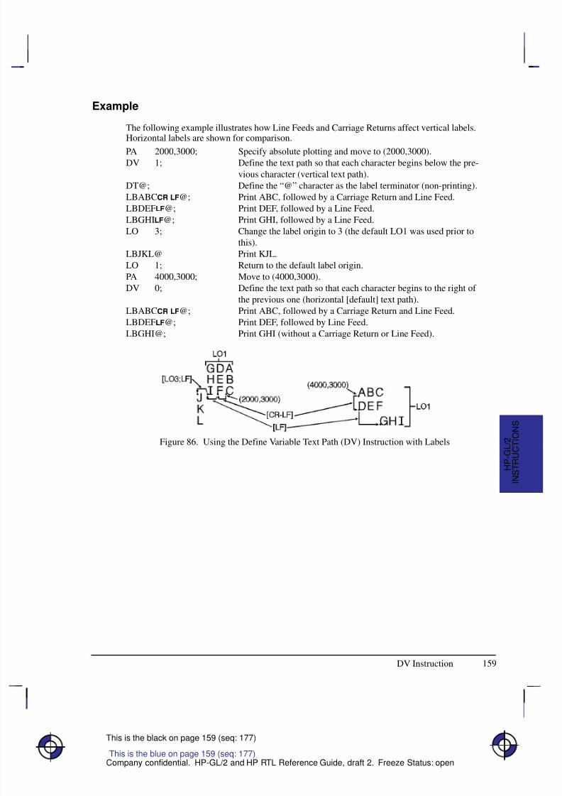
8/12/2019 HPGL2-RTL ReferenceGuide 5961-3526 540pages Sep96
http://slidepdf.com/reader/full/hpgl2-rtl-referenceguide-5961-3526-540pages-sep96 177/539
159
This is the black on page 159 (seq: 177)
Company confidential. HP-GL/2 and HP RTL Reference Guide, draft 2. Freeze Status: open
Example
The following example illustrates how Line Feeds and Carriage Returns affect vertical labels.
Horizontal labels are shown for comparison.PA 2000,3000; Specify absolute plotting and move to (2000,3000).
DV 1; Define the text path so that each character begins below the pre-
vious character (vertical text path).
DT@; Define the “@” character as the label terminator (non-printing).
LBABC @; Print ABC, followed by a Carriage Return and Line Feed.
LBDEF@; Print DEF, followed by a Line Feed.
LBGHI@; Print GHI, followed by a Line Feed.
LO 3; Change the label origin to 3 (the default LO1 was used prior to
this).
LBJKL@ Print KJL.
LO 1; Return to the default label origin.
PA 4000,3000; Move to (4000,3000).DV 0; Define the text path so that each character begins to the right of
the previous one (horizontal [default] text path).
LBABC @; Print ABC, followed by a Carriage Return and Line Feed.
LBDEF@; Print DEF, followed by Line Feed.
LBGHI@; Print GHI (without a Carriage Return or Line Feed).
Figure 86. Using the Define Variable Text Path (DV) Instruction with Labels
This is the blue on page 159 (seq: 177)
DV Instruction
I N S T R U C T I O N S
H P - G L / 2
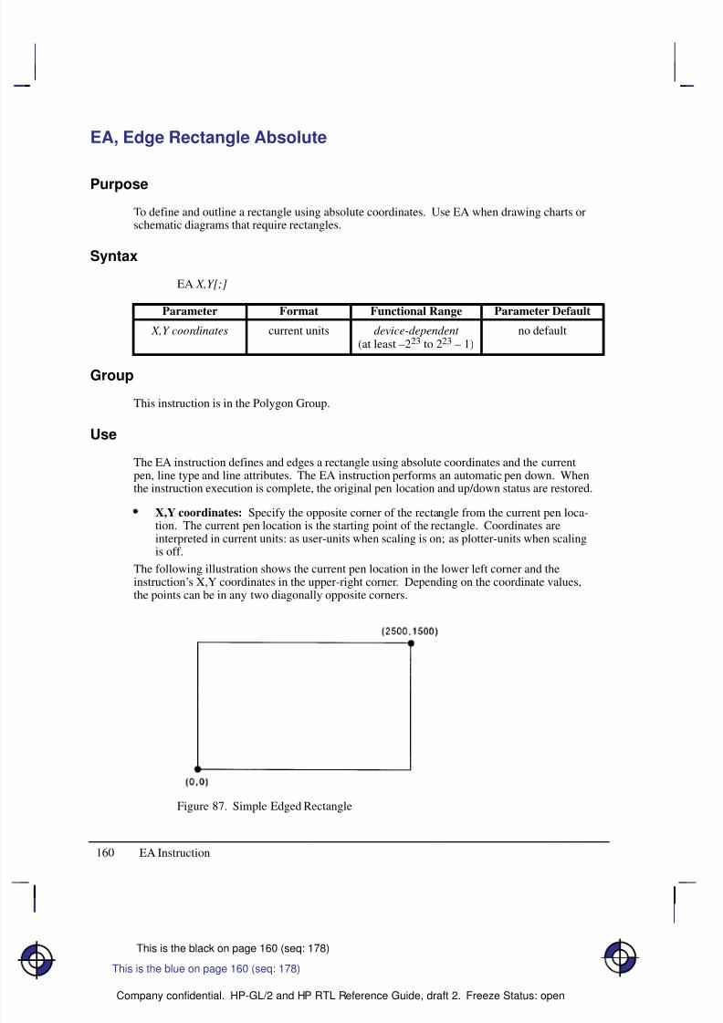
8/12/2019 HPGL2-RTL ReferenceGuide 5961-3526 540pages Sep96
http://slidepdf.com/reader/full/hpgl2-rtl-referenceguide-5961-3526-540pages-sep96 178/539
160
This is the black on page 160 (seq: 178)
Company confidential. HP-GL/2 and HP RTL Reference Guide, draft 2. Freeze Status: open
EA, Edge Rectangle Absolute
Purpose
To define and outline a rectangle using absolute coordinates. Use EA when drawing charts orschematic diagrams that require rectangles.
Syntax
EA X,Y[;]
Á Á Á Á Á Á Á
Á Á Á Á Á Á Á
ParameterÁ Á Á Á Á Á
Á Á Á Á Á Á
FormatÁ Á Á Á Á Á Á Á
Á Á Á Á Á Á Á Á
Functional RangeÁ Á Á Á Á Á Á Á
Á Á Á Á Á Á Á Á
Parameter Default
Á Á Á Á Á Á Á
Á Á Á Á Á Á Á
Á Á Á Á Á Á Á
X,Y coordinates Á Á Á Á Á Á
Á
Á Á Á Á Á
Á Á Á Á Á Á
current units Á Á Á Á Á Á Á Á
Á
Á Á Á Á Á Á Á
Á Á Á Á Á Á Á Á
device-dependent (at least –223 to 223 – 1)
Á Á Á Á Á Á Á Á
Á
Á Á Á Á Á Á Á
Á Á Á Á Á Á Á Á
no default
Group
This instruction is in the Polygon Group.
Use
The EA instruction defines and edges a rectangle using absolute coordinates and the currentpen, line type and line attributes. The EA instruction performs an automatic pen down. Whenthe instruction execution is complete, the original pen location and up/down status are restored.
X,Y coordinates: Specify the opposite corner of the rectangle from the current pen loca-tion. The current pen location is the starting point of the rectangle. Coordinates are
interpreted in current units: as user-units when scaling is on; as plotter-units when scalingis off.
The following illustration shows the current pen location in the lower left corner and theinstruction’s X,Y coordinates in the upper-right corner. Depending on the coordinate values,the points can be in any two diagonally opposite corners.
Figure 87. Simple Edged Rectangle
This is the blue on page 160 (seq: 178)
EA Instruction
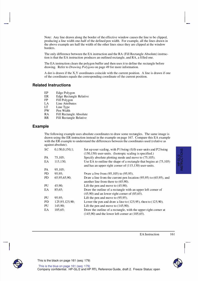
8/12/2019 HPGL2-RTL ReferenceGuide 5961-3526 540pages Sep96
http://slidepdf.com/reader/full/hpgl2-rtl-referenceguide-5961-3526-540pages-sep96 179/539
161
This is the black on page 161 (seq: 179)
Company confidential. HP-GL/2 and HP RTL Reference Guide, draft 2. Freeze Status: open
Note: Any line drawn along the border of the effective window causes the line to be clipped,producing a line width one-half of the defined pen width. For example, all the lines drawn inthe above example are half the width of the other lines since they are clipped at the window
borders.The only difference between the EA instruction and the RA (Fill Rectangle Absolute) instruc-tion is that the EA instruction produces an outlined rectangle, and RA, a filled one.
The EA instruction clears the polygon buffer and then uses it to define the rectangle beforedrawing. Refer to Drawing Polygons on page 49 for more information.
A dot is drawn if the X,Y coordinates coincide with the current position. A line is drawn if oneof the coordinates equals the corresponding coordinate of the current position.
Related Instructions
EP Edge PolygonER Edge Rectangle RelativeFP Fill PolygonLA Line AttributesLT Line TypePW Pen WidthRA Fill Rectangle AbsoluteRR Fill Rectangle Relative
Example
The following example uses absolute coordinates to draw some rectangles. The same image isdrawn using the ER instruction instead in the example on page 167. Compare this EA examplewith the ER example to understand the differences between the coordinates used (relative asagainst absolute).
SC 0,150,0,150,1; Set up user scaling, with P1 being (0,0) user-units and P2 being
(150,150) user-units. (Isotropic scaling is specified.)
PA 75,105; Specify absolute plotting mode and move to (75,105).
EA 115,130; Use EA to outline the shape of a rectangle that begins at (75,105)
and has an upper right corner of (115,130) user-units.
PA 95,105;
PD 95,95; Draw a line from (95,105) to (95,95).
PD 65,95,65,90; Draw a line from the current pen location (95,95) to (65,95), and
another line from there to (65,90).
PU 45,90; Lift the pen and move to (45,90).
EA 85,65; Draw the outline of a rectangle with an upper left corner of
(45,90) and an lower right corner of (85,65).
PU 95,95; Lift the pen and move to (95,95).PD 125,95,125,90; Lower the pen and draw a line to (125,95), then to (125,90).
PU 145,90; Lift the pen and move to (145,90).
EA 105,65; Draw the outline of a rectangle, with the upper right corner at
(145,90) and the lower left corner at (105,65).
This is the blue on page 161 (seq: 179)
EA Instruction
I N S T R U C T I O N S
H P - G L / 2
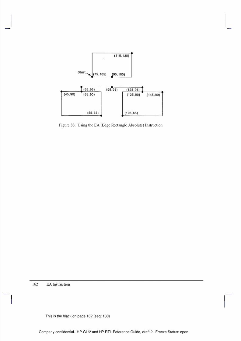
8/12/2019 HPGL2-RTL ReferenceGuide 5961-3526 540pages Sep96
http://slidepdf.com/reader/full/hpgl2-rtl-referenceguide-5961-3526-540pages-sep96 180/539
162
This is the black on page 162 (seq: 180)
Company confidential. HP-GL/2 and HP RTL Reference Guide, draft 2. Freeze Status: open
Figure 88. Using the EA (Edge Rectangle Absolute) Instruction
EA Instruction
8/12/2019 HPGL2-RTL ReferenceGuide 5961-3526 540pages Sep96
http://slidepdf.com/reader/full/hpgl2-rtl-referenceguide-5961-3526-540pages-sep96 181/539
163
This is the black on page 163 (seq: 181)
Company confidential. HP-GL/2 and HP RTL Reference Guide, draft 2. Freeze Status: open
EC, Enable Cutter
Purpose
To enable or disable the automatic cutter function on your device. Not all devices have an au-tomatic cutter.
Syntax
EC n[;]or
EC [;]
Á Á Á Á Á Á Á
Á Á Á Á Á Á Á
ParameterÁ Á Á Á Á Á Á
Á Á Á Á Á Á Á
FormatÁ Á Á Á Á Á Á Á
Á Á Á Á Á Á Á Á
Functional RangeÁ Á Á Á Á Á Á
Á Á Á Á Á Á Á
Parameter DefaultÁ Á Á Á Á Á Á
Á Á Á Á Á Á Á
Á Á Á Á Á Á Á
n
Á Á Á Á Á Á Á
Á Á Á Á Á Á Á
Á Á Á Á Á Á Á
clamped integer
Á Á Á Á Á Á Á Á
Á Á Á Á Á Á Á Á
Á Á Á Á Á Á Á Á
–32 768 to 32 767
Á Á Á Á Á Á Á
Á Á Á Á Á Á Á
Á Á Á Á Á Á Á
no parameter(enabled)
Group
This instruction is in the Technical Graphics Extension.
Use
If the cutter is enabled, cutting is done after each PG and RP instruction. Roll-feed devices thatdo not have a cutter may draw a line where the media should be cut.
No parameters: Enables the cutter function. This is the default condition.
n: Disables the cutter function. This may be any number (a clamped integer) in thedevice’s range.
This is the blue on page 163 (seq: 181)
EC Instruction
I N S T R U C T I O N S
H P - G L / 2
8/12/2019 HPGL2-RTL ReferenceGuide 5961-3526 540pages Sep96
http://slidepdf.com/reader/full/hpgl2-rtl-referenceguide-5961-3526-540pages-sep96 182/539
164
This is the black on page 164 (seq: 182)
Company confidential. HP-GL/2 and HP RTL Reference Guide, draft 2. Freeze Status: open
EP, Edge Polygon
Purpose
To outline the polygon currently stored in the polygon buffer. Use EP to edge polygons thatyou defined in polygon mode and with the Fill Rectangle and Wedge instructions (RA, RR, andWG).
Syntax
EP [;]
Group
This instruction is in the Polygon Group.
Use
The EP instruction outlines any polygon that is currently in the polygon buffer. This includeswedges and rectangles defined using the EA, ER, EW, RA, RR, and WG instructions. EP ac-cesses the data in the polygon buffer, but does not clear the buffer or change the data in anyway.
The EP instruction only edges between points that were defined with the pen down, using thecurrent pen, line type and attributes. When the instruction execution is complete, the originalpen location and up/down status are restored.
EP is ignored in polygon mode (after “PM0” and before “PM2”) or whenever the buffer is
empty.
Related Instructions
EA Edge Rectangle AbsoluteER Edge Rectangle RelativeEW Edge WedgeLA Line AttributesLT Line TypePM Polygon ModePW Pen WidthRA Fill Rectangle AbsoluteRR Fill Rectangle Relative
WG Fill Wedge
This is the blue on page 164 (seq: 182)
EP Instruction

8/12/2019 HPGL2-RTL ReferenceGuide 5961-3526 540pages Sep96
http://slidepdf.com/reader/full/hpgl2-rtl-referenceguide-5961-3526-540pages-sep96 183/539
165
This is the black on page 165 (seq: 183)
Company confidential. HP-GL/2 and HP RTL Reference Guide, draft 2. Freeze Status: open
Example
The following example creates a shape in polygon mode, then uses EP to outline it.
PA 2000,10; Specify absolute plotting and move to position (2000,10).PM 0; Enter polygon mode.
PD 10,2000,10,10,2000,10; Store a pen down instruction, and then store points (10,2000),
(10,10), and (2000,10).
PM 1; Close the polygon.
PU 610,610; While still in polygon mode, lift the pen and move to (610,610).
CI 500; Draw a circle with a diameter of 500 plotter-units.
PM 2; Close the current subpolygon and exit polygon mode.
EP ; Outline the polygon that was just stored in the polygon buffer.
Figure 89. Using the EP (Edge Polygon) Instruction
This is the blue on page 165 (seq: 183)
EP Instruction
I N S T R U C T I O N S
H P - G L / 2
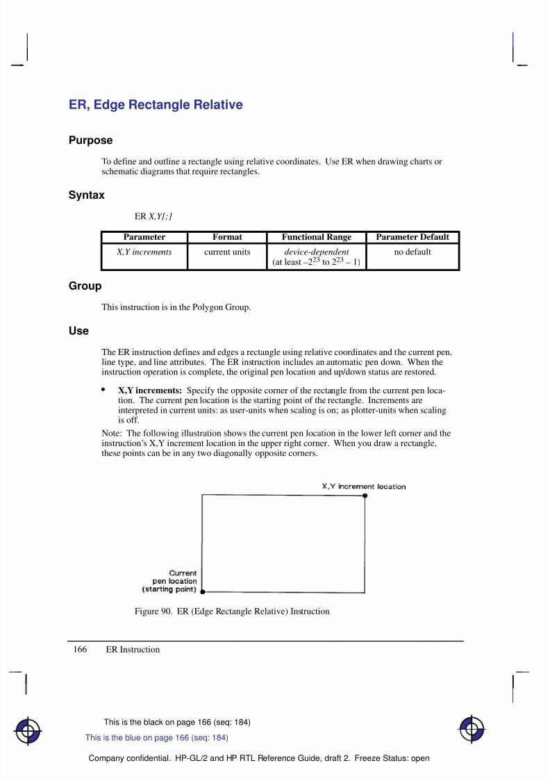
8/12/2019 HPGL2-RTL ReferenceGuide 5961-3526 540pages Sep96
http://slidepdf.com/reader/full/hpgl2-rtl-referenceguide-5961-3526-540pages-sep96 184/539
166
This is the black on page 166 (seq: 184)
Company confidential. HP-GL/2 and HP RTL Reference Guide, draft 2. Freeze Status: open
ER, Edge Rectangle Relative
Purpose
To define and outline a rectangle using relative coordinates. Use ER when drawing charts orschematic diagrams that require rectangles.
Syntax
ER X,Y[;]
Á Á Á Á Á Á Á
Á Á Á Á Á Á Á
ParameterÁ Á Á Á Á Á
Á Á Á Á Á Á
FormatÁ Á Á Á Á Á Á Á
Á Á Á Á Á Á Á Á
Functional RangeÁ Á Á Á Á Á Á Á
Á Á Á Á Á Á Á Á
Parameter Default
Á Á Á Á Á Á Á
Á Á Á Á Á Á Á
Á Á Á Á Á Á Á
X,Y increments Á Á Á Á Á Á
Á
Á Á Á Á Á
Á Á Á Á Á Á
current units Á Á Á Á Á Á Á Á
Á
Á Á Á Á Á Á Á
Á Á Á Á Á Á Á Á
device-dependent (at least –223 to 223 – 1)
Á Á Á Á Á Á Á Á
Á
Á Á Á Á Á Á Á
Á Á Á Á Á Á Á Á
no default
Group
This instruction is in the Polygon Group.
Use
The ER instruction defines and edges a rectangle using relative coordinates and the current pen,line type, and line attributes. The ER instruction includes an automatic pen down. When theinstruction operation is complete, the original pen location and up/down status are restored.
X,Y increments: Specify the opposite corner of the rectangle from the current pen loca-tion. The current pen location is the starting point of the rectangle. Increments are
interpreted in current units: as user-units when scaling is on; as plotter-units when scalingis off.
Note: The following illustration shows the current pen location in the lower left corner and theinstruction’s X,Y increment location in the upper right corner. When you draw a rectangle,these points can be in any two diagonally opposite corners.
Figure 90. ER (Edge Rectangle Relative) Instruction
This is the blue on page 166 (seq: 184)
ER Instruction
8/12/2019 HPGL2-RTL ReferenceGuide 5961-3526 540pages Sep96
http://slidepdf.com/reader/full/hpgl2-rtl-referenceguide-5961-3526-540pages-sep96 185/539
167
This is the black on page 167 (seq: 185)
Company confidential. HP-GL/2 and HP RTL Reference Guide, draft 2. Freeze Status: open
The only difference between the ER instruction and the RR (Fill Relative Rectangle) instructionis that the ER instruction produces an outlined rectangle, and RR, a filled one.
The ER instruction clears the polygon buffer and then uses it to define the rectangle beforedrawing. Refer to Using the Polygon Buffer on page 45 for more information.
A dot is drawn if both X and Y coordinates are zero. A line is drawn if one of the coordinatesis zero.
Related Instructions
EA Edge Rectangle AbsoluteEP Edge PolygonFP Fill PolygonLA Line AttributesLT Line TypePW Pen Width
RA Fill Rectangle AbsoluteRR Fill Rectangle Relative
Example
The following example uses relative coordinates to draw the same image shown in the EAinstruction example. Compare this example with the EA example to understand the differencesbetween the coordinates used.
SC 0,150,0,150,1; Specify user scaling, with P1 being (0,0) and P2 (150,150); the
“1” indicates isotropic scaling.
PA 75,105; Enter absolute plotting mode and move to (75,105).
ER 40,25; Draw a rectangle using the current pen location as the lower left
corner and a point (40,25) user-units away as the upper right cor-
ner.
PR 20,0; Specify relative plotting and move the pen 20 user-units to the
right.
PD 0,–10; Place the pen down and draw a line to a point 10 user-units down.
PD –30,0,0,–5; With the pen down, move 30 user-units to the left and 5 units
down.
PU –20,0; Lift the pen and move 20 user-units to the left.
ER 40,–25; Draw the outline of a rectangle with the current pen location as
one corner and a point (40,–25) user-units away as the opposite
corner.
PU 50,5; Lift the pen and move 50 user-units to the right and 5 units up.
PD 30,0, 0,–5; Place the pen down and draw a line 30 user-units to the right, then
5 units down.PU 20,0; Lift the pen and move 20 user-units to the right.
ER –40,–25; Draw a rectangle from that point, with the current pen location
being one corner and the opposite corner being 40 user-units to the
left and 25 units down.
This is the blue on page 167 (seq: 185)
ER Instruction
I N S T R U C T I O N S
H P - G L / 2
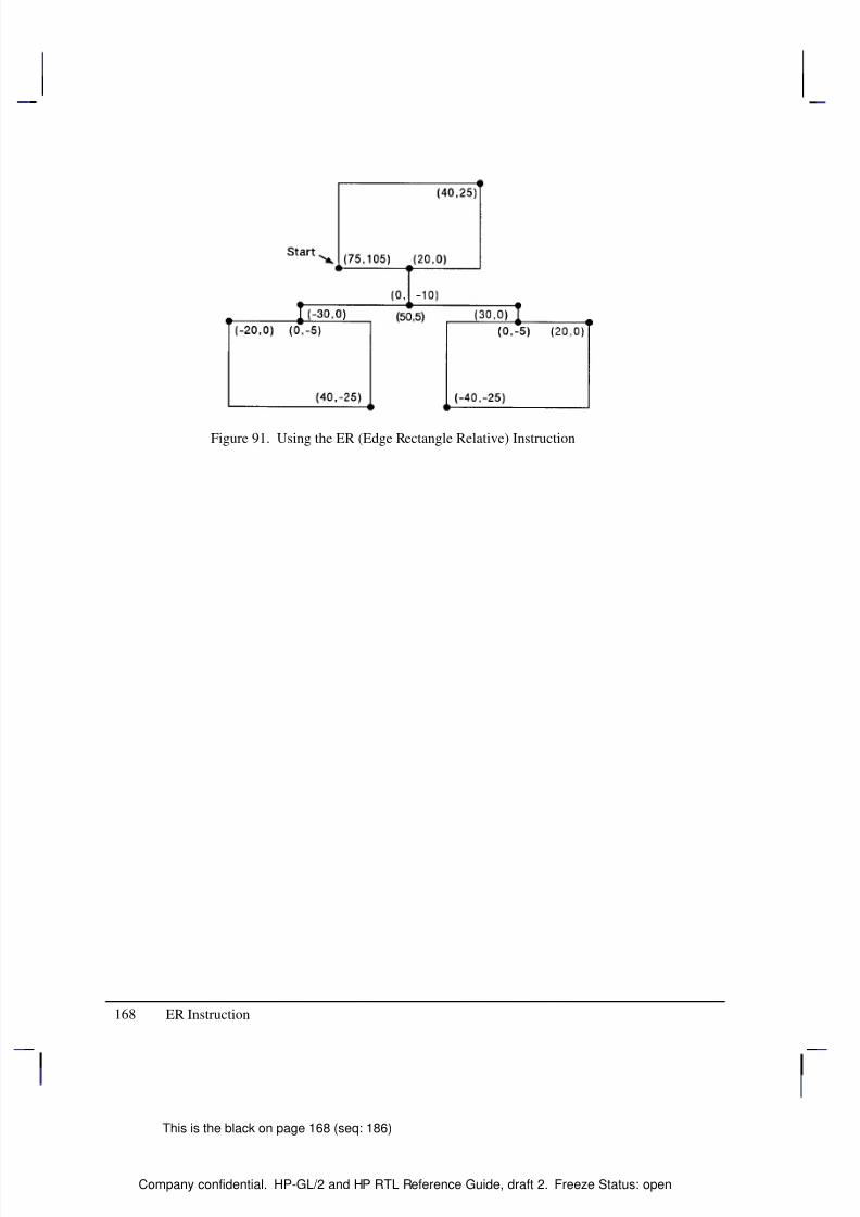
8/12/2019 HPGL2-RTL ReferenceGuide 5961-3526 540pages Sep96
http://slidepdf.com/reader/full/hpgl2-rtl-referenceguide-5961-3526-540pages-sep96 186/539
168
This is the black on page 168 (seq: 186)
Company confidential. HP-GL/2 and HP RTL Reference Guide, draft 2. Freeze Status: open
Figure 91. Using the ER (Edge Rectangle Relative) Instruction
ER Instruction
8/12/2019 HPGL2-RTL ReferenceGuide 5961-3526 540pages Sep96
http://slidepdf.com/reader/full/hpgl2-rtl-referenceguide-5961-3526-540pages-sep96 187/539
169
This is the black on page 169 (seq: 187)
Company confidential. HP-GL/2 and HP RTL Reference Guide, draft 2. Freeze Status: open
ES, Extra Space
Purpose
To adjust the space between characters and lines of labels without affecting the character size.
Syntax
ES width[,height][;]or
ES [;]
Á Á Á Á Á Á Á
ParameterÁ Á Á Á Á Á Á
FormatÁ Á Á Á Á Á Á Á
Functional RangeÁ Á Á Á Á Á Á
Parameter DefaultÁ Á Á Á Á Á Á
Á
Á Á Á Á Á Á
Á Á Á Á Á Á Á
width
Á Á Á Á Á Á Á
Á
Á Á Á Á Á Á
Á Á Á Á Á Á Á
clamped realÁ Á Á Á Á Á Á Á
Á
Á Á Á Á Á Á Á
Á Á Á Á Á Á Á Á
–32 768 to 32 767Á Á Á Á Á Á Á
Á
Á Á Á Á Á Á
Á Á Á Á Á Á Á
0
Á Á Á Á Á Á Á
Á Á Á Á Á Á Á
height Á Á Á Á Á Á Á
Á Á Á Á Á Á Á
clamped real Á Á Á Á Á Á Á Á
Á Á Á Á Á Á Á Á
–32 768 to 32 767 Á Á Á Á Á Á Á
Á Á Á Á Á Á Á
0
Group
This instruction is in the Character Group.
Use
The device interprets the parameters as follows:
No Parameters: Defaults the spaces and lines between characters to no extra space.Equivalent to “ES0,0”.
width: Specifies an increase (positive number) or decrease (negative number) in the spacebetween characters. The width parameter is a fraction of the character plot cell width. Forexample, “ES.15” under default conditions causes the CP cell width to increase by 15%(1.15 its current width). Character images are not supported by ES. For maximumlegibility, do not specify more than one extra space or subtract more than half a space.
height: Specifies an increase (positive number) or decrease (negative number) in the spacebetween lines. The height parameter is a fraction of the line feed height of the characterplot cell. For maximum legibility, do not specify more than two extra lines, or subtractmore than half a line.
For proportionally spaced fonts, the ES percentage applies to each individual character cell;therefore cell size varies from character to character.
An ES instruction remains in effect until another ES instruction is executed, or until the device
is initialized or set to default conditions.
Related Instructions
CP Character PlotLB Label
This is the blue on page 169 (seq: 187)
ES Instruction
I N S T R U C T I O N S
H P - G L / 2
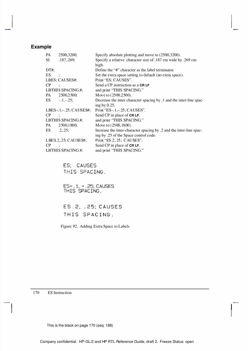
8/12/2019 HPGL2-RTL ReferenceGuide 5961-3526 540pages Sep96
http://slidepdf.com/reader/full/hpgl2-rtl-referenceguide-5961-3526-540pages-sep96 188/539
170
This is the black on page 170 (seq: 188)
Company confidential. HP-GL/2 and HP RTL Reference Guide, draft 2. Freeze Status: open
Example
PA 2500,3200; Specify absolute plotting and move to (2500,3200).
SI .187,.269; Specify a relative character size of .187 cm wide by .269 cmhigh.
DT#; Define the “#” character as the label terminator.
ES ; Set the extra space setting to default (no extra space).
LBES; CAUSES#; Print “ES; CAUSES”.
CP ; Send a CP instruction as a
LBTHIS SPACING.#; and print “THIS SPACING.”
PA 2500,2500; Move to (2500,2500).
ES –.1,–.25; Decrease the inter-character spacing by .1 and the inter-line spac-
ing by 0.25.
LBES–.1,–.25; CAUSES#; Print “ES–.1,–.25; CAUSES”.
CP ; Send CP in place of ,
LBTHIS SPACING.#; and print “THIS SPACING.”
PA 2500,1800; Move to (2500,1800).
ES .2,.25; Increase the inter-character spacing by .2 and the inter-line spac-
ing by .25 of the Space control code.
LBES.2,.25; CAUSES#; Print “ES.2,.25; CAUSES”.
CP ; Send CP in place of ,
LBTHIS SPACING.#; and print “THIS SPACING.”
Figure 92. Adding Extra Space to Labels
ES Instruction
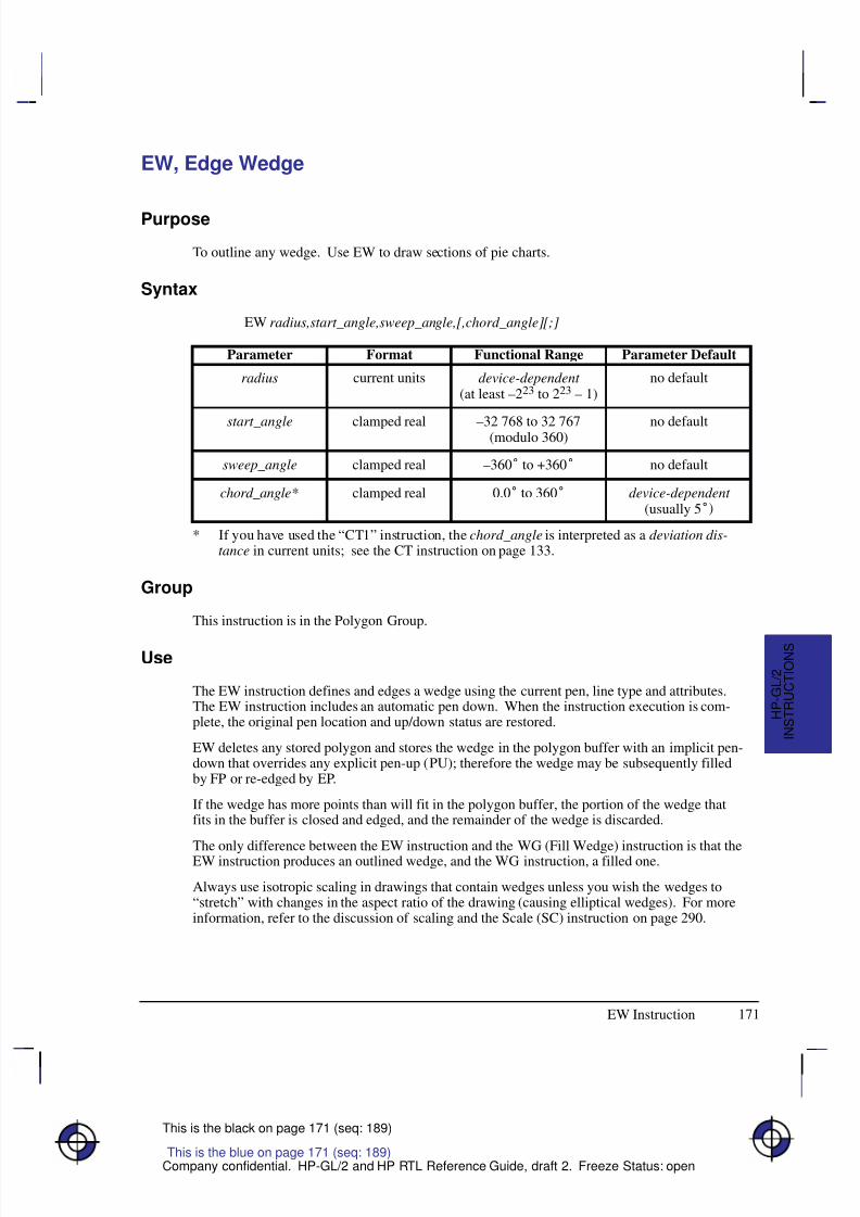
8/12/2019 HPGL2-RTL ReferenceGuide 5961-3526 540pages Sep96
http://slidepdf.com/reader/full/hpgl2-rtl-referenceguide-5961-3526-540pages-sep96 189/539
171
This is the black on page 171 (seq: 189)
Company confidential. HP-GL/2 and HP RTL Reference Guide, draft 2. Freeze Status: open
EW, Edge Wedge
Purpose
To outline any wedge. Use EW to draw sections of pie charts.
Syntax
EW radius,start_angle,sweep_angle,[,chord_angle][;]
Á Á Á Á Á Á Á
Á Á Á Á Á Á Á
Parameter Á Á Á Á Á Á Á
Á Á Á Á Á Á Á
Format Á Á Á Á Á Á Á Á
Á Á Á Á Á Á Á Á
Functional Range Á Á Á Á Á Á Á
Á Á Á Á Á Á Á
Parameter DefaultÁ Á Á Á Á Á Á
Á
Á Á Á Á Á Á
Á Á Á Á Á Á Á
radiusÁ Á Á Á Á Á Á
Á
Á Á Á Á Á Á
Á Á Á Á Á Á Á
current unitsÁ Á Á Á Á Á Á Á
Á
Á Á Á Á Á Á Á
Á Á Á Á Á Á Á Á
device-dependent (at least –223 to 223 – 1)
Á Á Á Á Á Á Á
Á
Á Á Á Á Á Á
Á Á Á Á Á Á Á
no default
Á Á Á Á Á Á Á
Á Á Á Á Á Á Á
Á Á Á Á Á Á Á
start_angle
Á Á Á Á Á Á Á
Á Á Á Á Á Á Á
Á Á Á Á Á Á Á
clamped real
Á Á Á Á Á Á Á Á
Á Á Á Á Á Á Á Á
Á Á Á Á Á Á Á Á
–32 768 to 32 767(modulo 360)
Á Á Á Á Á Á Á
Á Á Á Á Á Á Á
Á Á Á Á Á Á Á
no default
Á Á Á Á Á Á Á
Á Á Á Á Á Á Á
sweep_angle Á Á Á Á Á Á Á
Á Á Á Á Á Á Á
clamped real Á Á Á Á Á Á Á Á
Á Á Á Á Á Á Á Á
–360 to +360 Á Á Á Á Á Á Á
Á Á Á Á Á Á Á
no defaultÁ Á Á Á Á Á Á
Á
Á Á Á Á Á Á
Á Á Á Á Á Á Á
chord_angle*Á Á Á Á Á Á Á
Á
Á Á Á Á Á Á
Á Á Á Á Á Á Á
clamped realÁ Á Á Á Á Á Á Á
Á
Á Á Á Á Á Á Á
Á Á Á Á Á Á Á Á
0.0 to 360Á Á Á Á Á Á Á
Á
Á Á Á Á Á Á
Á Á Á Á Á Á Á
device-dependent (usually 5
* If you have used the “CT1” instruction, the chord_angle is interpreted as a deviation dis-tance in current units; see the CT instruction on page 133.
Group
This instruction is in the Polygon Group.
Use
The EW instruction defines and edges a wedge using the current pen, line type and attributes.The EW instruction includes an automatic pen down. When the instruction execution is com-plete, the original pen location and up/down status are restored.
EW deletes any stored polygon and stores the wedge in the polygon buffer with an implicit pen-down that overrides any explicit pen-up (PU); therefore the wedge may be subsequently filledby FP or re-edged by EP.
If the wedge has more points than will fit in the polygon buffer, the portion of the wedge thatfits in the buffer is closed and edged, and the remainder of the wedge is discarded.
The only difference between the EW instruction and the WG (Fill Wedge) instruction is that theEW instruction produces an outlined wedge, and the WG instruction, a filled one.
Always use isotropic scaling in drawings that contain wedges unless you wish the wedges to“stretch” with changes in the aspect ratio of the drawing (causing elliptical wedges). For moreinformation, refer to the discussion of scaling and the Scale (SC) instruction on page 290.
This is the blue on page 171 (seq: 189)
EW Instruction
I N S T R U C T I O N S
H P - G L / 2
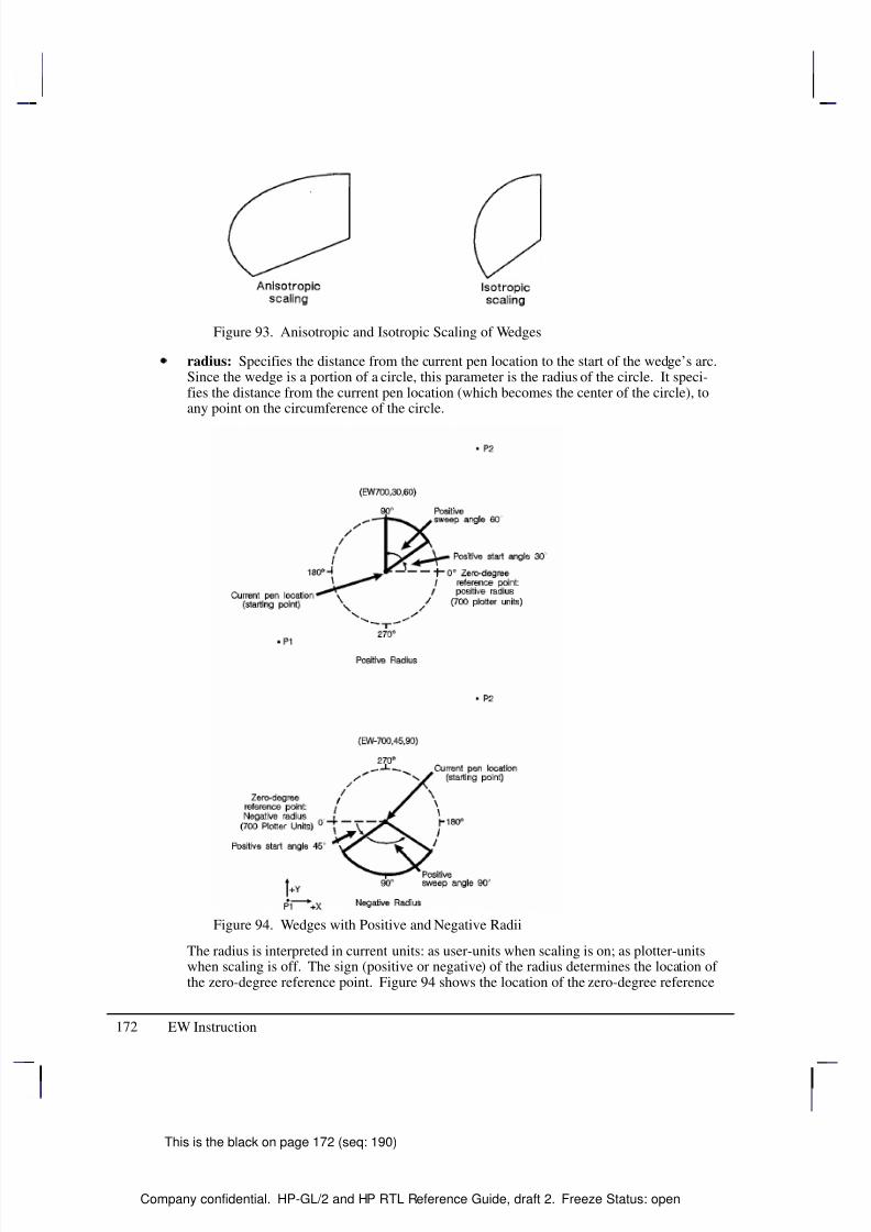
8/12/2019 HPGL2-RTL ReferenceGuide 5961-3526 540pages Sep96
http://slidepdf.com/reader/full/hpgl2-rtl-referenceguide-5961-3526-540pages-sep96 190/539
172
This is the black on page 172 (seq: 190)
Company confidential. HP-GL/2 and HP RTL Reference Guide, draft 2. Freeze Status: open
Figure 93. Anisotropic and Isotropic Scaling of Wedges
radius: Specifies the distance from the current pen location to the start of the wedge’s arc.Since the wedge is a portion of a circle, this parameter is the radius of the circle. It speci-fies the distance from the current pen location (which becomes the center of the circle), toany point on the circumference of the circle.
Figure 94. Wedges with Positive and Negative Radii
The radius is interpreted in current units: as user-units when scaling is on; as plotter-unitswhen scaling is off. The sign (positive or negative) of the radius determines the location of the zero-degree reference point. Figure 94 shows the location of the zero-degree reference
EW Instruction
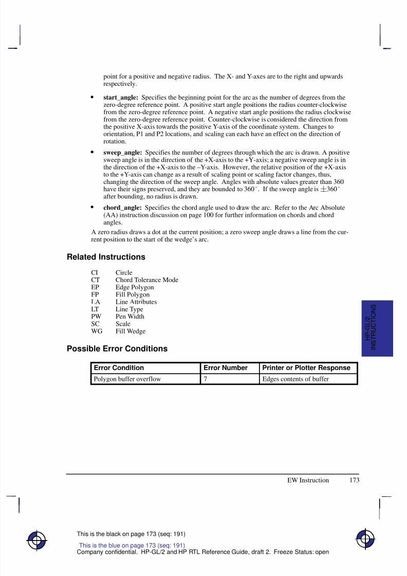
8/12/2019 HPGL2-RTL ReferenceGuide 5961-3526 540pages Sep96
http://slidepdf.com/reader/full/hpgl2-rtl-referenceguide-5961-3526-540pages-sep96 191/539
173
This is the black on page 173 (seq: 191)
Company confidential. HP-GL/2 and HP RTL Reference Guide, draft 2. Freeze Status: open
point for a positive and negative radius. The X- and Y-axes are to the right and upwardsrespectively.
start_angle: Specifies the beginning point for the arc as the number of degrees from thezero-degree reference point. A positive start angle positions the radius counter-clockwisefrom the zero-degree reference point. A negative start angle positions the radius clockwisefrom the zero-degree reference point. Counter-clockwise is considered the direction fromthe positive X-axis towards the positive Y-axis of the coordinate system. Changes toorientation, P1 and P2 locations, and scaling can each have an effect on the direction of rotation.
sweep_angle: Specifies the number of degrees through which the arc is drawn. A positivesweep angle is in the direction of the +X-axis to the +Y-axis; a negative sweep angle is inthe direction of the +X-axis to the –Y-axis. However, the relative position of the +X-axisto the +Y-axis can change as a result of scaling point or scaling factor changes, thus,changing the direction of the sweep angle. Angles with absolute values greater than 360have their signs preserved, and they are bounded to 360. If the sweep angle is360after bounding, no radius is drawn.
chord_angle: Specifies the chord angle used to draw the arc. Refer to the Arc Absolute(AA) instruction discussion on page 100 for further information on chords and chordangles.
A zero radius draws a dot at the current position; a zero sweep angle draws a line from the cur-rent position to the start of the wedge’s arc.
Related Instructions
CI CircleCT Chord Tolerance ModeEP Edge PolygonFP Fill Polygon
LA Line AttributesLT Line TypePW Pen WidthSC ScaleWG Fill Wedge
Possible Error Conditions
Error Condition Error Number Printer or Plotter Response
Polygon buffer overflow 7 Edges contents of buffer
This is the blue on page 173 (seq: 191)
EW Instruction
I N S T R U C T I O N S
H P - G L / 2
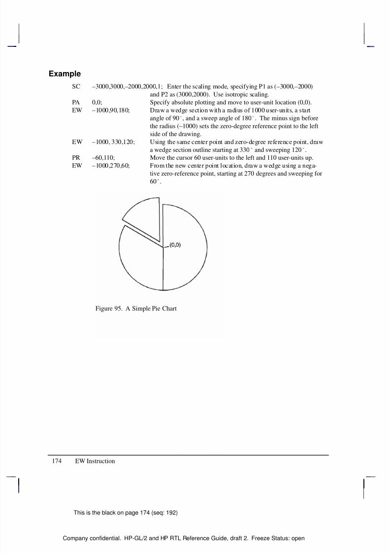
8/12/2019 HPGL2-RTL ReferenceGuide 5961-3526 540pages Sep96
http://slidepdf.com/reader/full/hpgl2-rtl-referenceguide-5961-3526-540pages-sep96 192/539
174
This is the black on page 174 (seq: 192)
Company confidential. HP-GL/2 and HP RTL Reference Guide, draft 2. Freeze Status: open
Example
SC –3000,3000,–2000,2000,1; Enter the scaling mode, specifying P1 as (–3000,–2000)
and P2 as (3000,2000). Use isotropic scaling.PA 0,0; Specify absolute plotting and move to user-unit location (0,0).
EW –1000,90,180; Draw a wedge section with a radius of 1000 user-units, a start
angle of 90, and a sweep angle of 180. The minus sign before
the radius (–1000) sets the zero-degree reference point to the left
side of the drawing.
EW –1000, 330,120; Using the same center point and zero-degree reference point, draw
a wedge section outline starting at 330 and sweeping 120.
PR –60,110; Move the cursor 60 user-units to the left and 110 user-units up.
EW –1000,270,60; From the new center point location, draw a wedge using a nega-
tive zero-reference point, starting at 270 degrees and sweeping for
60.
Figure 95. A Simple Pie Chart
EW Instruction
8/12/2019 HPGL2-RTL ReferenceGuide 5961-3526 540pages Sep96
http://slidepdf.com/reader/full/hpgl2-rtl-referenceguide-5961-3526-540pages-sep96 193/539
175
This is the black on page 175 (seq: 193)
Company confidential. HP-GL/2 and HP RTL Reference Guide, draft 2. Freeze Status: open
FI, Primary Font Selection by ID
Purpose
To designate any font that has been assigned a font ID as the primary (standard) font. Font IDsare assigned in the PCL environment.
Syntax
FI font_ID[;]Á Á Á Á Á Á Á
Á Á Á Á Á Á Á
ParameterÁ Á Á Á Á Á Á Á
Á Á Á Á Á Á Á Á
FormatÁ Á Á Á Á Á Á
Á Á Á Á Á Á Á
Functional RangeÁ Á Á Á Á Á Á Á
Á Á Á Á Á Á Á Á
Parameter DefaultÁ Á Á Á Á Á Á
Á Á Á Á Á Á Á
font_IDÁ Á Á Á Á Á Á Á
Á Á Á Á Á Á Á Á
integerÁ Á Á Á Á Á Á
Á Á Á Á Á Á Á
0 to 32767Á Á Á Á Á Á Á Á
Á Á Á Á Á Á Á Á
no default
Group
This instruction is in the Dual-Context Extension for PCL-devices only. HP RTL does not haveany support for fonts.
Use
font_ID: A non-negative integer assigned in the PCL environment. If the designated fontis present, the primary font attributes are set to those of the selected font. If the selectedfont is proportionally spaced, the pitch attribute is not changed. The instruction is ignoredif no font exists with the specified ID.
This instruction allows any accessible font that has been assigned a font_ID number to be se-lected as the primary (standard) font (the font characteristics are assigned to the standard font).As mentioned, the font must be accessible to the device as either a resident font, a downloadedfont, or a loaded cartridge font. To be selected, the font must have been previously assigned afont ID number in PCL mode. Also, for scalable fonts, the FI instruction must be preceded byan SD instruction specifying the font’s point size or pitch (see the example below).
When the device receives this instruction and the requested font is present, the primary fontcharacteristics are set to those of the requested font. If the selected font is proportionallyspaced, the pitch characteristic is not changed.
This instruction does not select the font for label printing if you are currently using thealternate font.
The FI instruction implicitly changes the value of SB. For example, if “SB0;” is in effectand FI selects a bitmap font, SB is set to 1. This affects the performance of certain HP-GL/2 instructions. Refer to the SB instruction on page 288.
Related Instructions and Commands
AD Alternate Font DefinitionFN Secondary Font Selection by IDLB LabelSA Select Alternate FontSB Scalable or Bitmap FontsSD Standard Font DefinitionSS Select Standard Font
This is the blue on page 175 (seq: 193)
FI Instruction
I N S T R U C T I O N S
H P - G L / 2
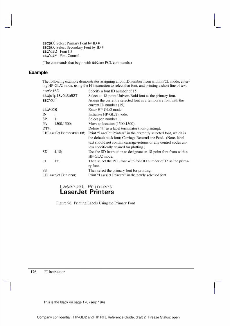
8/12/2019 HPGL2-RTL ReferenceGuide 5961-3526 540pages Sep96
http://slidepdf.com/reader/full/hpgl2-rtl-referenceguide-5961-3526-540pages-sep96 194/539
176
This is the black on page 176 (seq: 194)
Company confidential. HP-GL/2 and HP RTL Reference Guide, draft 2. Freeze Status: open
(#X Select Primary Font by ID #)#X Select Secondary Font by ID #*c#D Font ID
*c#F Font Control(The commands that begin with are PCL commands.)
Example
The following example demonstrates assigning a font ID number from within PCL mode, enter-ing HP-GL/2 mode, using the FI instruction to select that font, and printing a short line of text.
*c15D Specify a font ID number of 15.
(s1p18v0s3b52T Select an 18-point Univers Bold font as the primary font.
*c6F Assign the currently selected font as a temporary font with the
current ID number (15).
%0B Enter HP-GL/2 mode.
IN ; Initialize HP-GL/2 mode.SP 1; Select pen number 1.
PA 1500,1500; Move to location (1500,1500).
DT#; Define “#” as a label terminator (non-printing).
LBLaserJet Printers #; Print “LaserJet Printers” in the currently selected font, which is
the default stick font; Carriage Return/Line Feed. (Note, label
text should not contain carriage-returns or any control codes un-
less specifically desired for plotting.)
SD 4,18; Use the SD instruction to designate an 18-point font from within
HP-GL/2 mode.
FI 15; Then select the PCL font with font ID number of 15 as the prima-
ry font.
SS Then select the primary font for printing.LBLaserJet Printers#; Print “LaserJet Printers” in the newly selected font.
Figure 96. Printing Labels Using the Primary Font
FI Instruction
8/12/2019 HPGL2-RTL ReferenceGuide 5961-3526 540pages Sep96
http://slidepdf.com/reader/full/hpgl2-rtl-referenceguide-5961-3526-540pages-sep96 195/539
177
This is the black on page 177 (seq: 195)
Company confidential. HP-GL/2 and HP RTL Reference Guide, draft 2. Freeze Status: open
FN, Secondary Font Selection by ID
Purpose
To designate any font that has been assigned a font ID as the secondary (alternate) font. FontIDs are assigned in the PCL environment.
Syntax
FN font_ID[;]Á Á Á Á Á Á Á
Á Á Á Á Á Á Á
ParameterÁ Á Á Á Á Á Á Á
Á Á Á Á Á Á Á Á
FormatÁ Á Á Á Á Á Á
Á Á Á Á Á Á Á
Functional RangeÁ Á Á Á Á Á Á Á
Á Á Á Á Á Á Á Á
Parameter DefaultÁ Á Á Á Á Á Á
Á Á Á Á Á Á Á
font_IDÁ Á Á Á Á Á Á Á
Á Á Á Á Á Á Á Á
integerÁ Á Á Á Á Á Á
Á Á Á Á Á Á Á
0 to 32767Á Á Á Á Á Á Á Á
Á Á Á Á Á Á Á Á
no default
Group
This instruction is in the Dual-Context Extension for PCL-devices only. HP RTL does not haveany support for fonts.
Use
font_ID: A non-negative integer assigned in the PCL environment. If the designated fontis present, the secondary font attributes are set to those of the selected font. If the selectedfont is proportionally spaced, the pitch attribute is not changed. The instruction is ignoredif no font exists with the specified ID.
This instruction allows any accessible font that has been assigned a font_ID number to be se-lected as the secondary (alternate) font (the font characteristics are assigned to the secondaryfont). The font must be accessible to the device as either a resident font, a downloaded font, ora loaded cartridge font. To be selected, the font must have been previously assigned a font IDnumber in PCL mode. Also, for scalable fonts, the FN instruction must be accompanied by anAD instruction specifying the font’s point size (see the example below).
When the device receives this instruction and the requested font is present, the secondary fontcharacteristics are set to those of the requested font. If the selected font is proportionallyspaced, the pitch characteristic is not changed.
This instruction does not select the font for label printing if you are currently using thestandard font.
The FN instruction implicitly changes the value of SB. For example, if “SB0;” is in effectand FN selects a bitmap font, SB is set to 1. This affects the performance of certain HP-GL/2 instructions. Refer to the SB instruction on page 288.
Related Instructions
AD Alternate Font DefinitionFI Primary Font Selection by IDLB LabelSA Select Alternate FontSB Scalable or Bitmap FontsSD Standard Font DefinitionSS Select Standard Font
This is the blue on page 177 (seq: 195)
FN Instruction
I N S T R U C T I O N S
H P - G L / 2
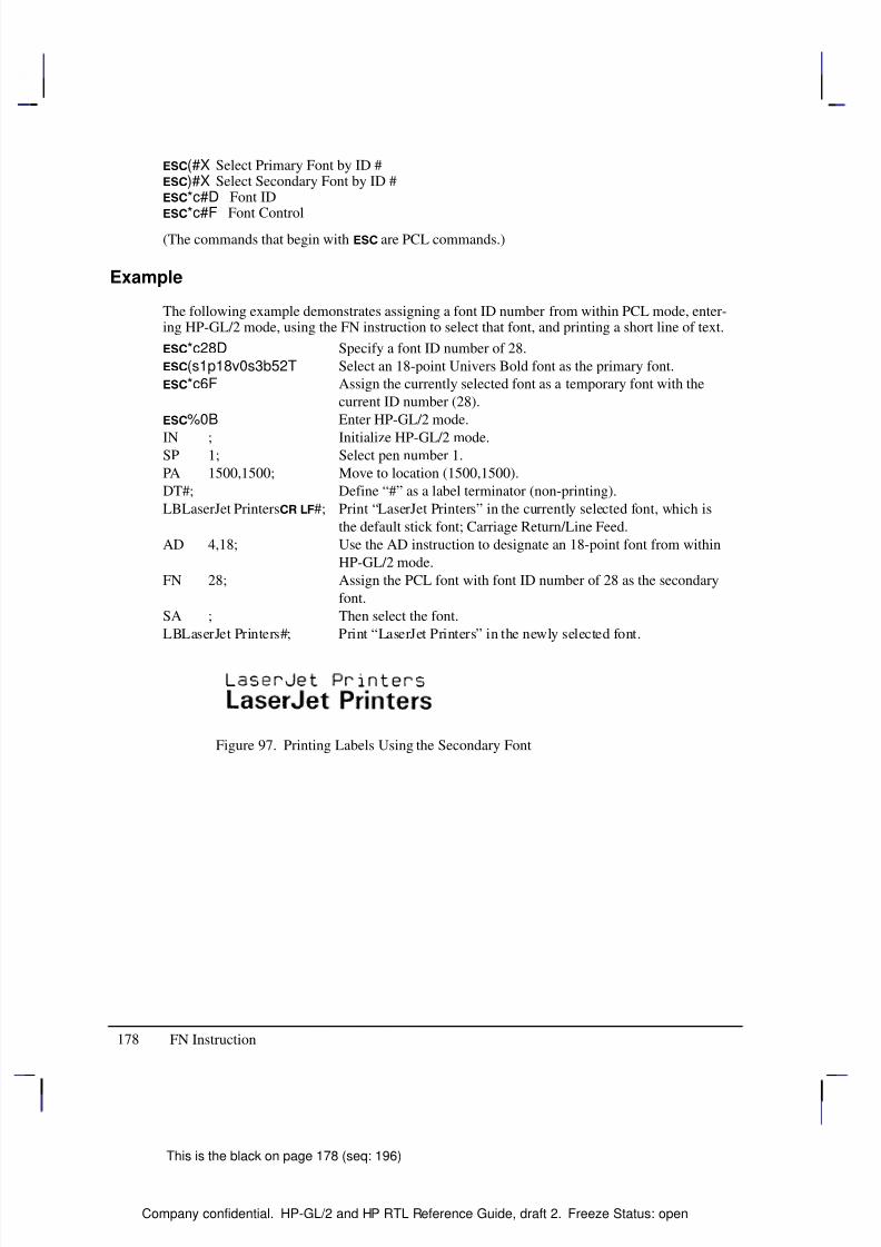
8/12/2019 HPGL2-RTL ReferenceGuide 5961-3526 540pages Sep96
http://slidepdf.com/reader/full/hpgl2-rtl-referenceguide-5961-3526-540pages-sep96 196/539
178
This is the black on page 178 (seq: 196)
Company confidential. HP-GL/2 and HP RTL Reference Guide, draft 2. Freeze Status: open
(#X Select Primary Font by ID #)#X Select Secondary Font by ID #*c#D Font ID
*c#F Font Control(The commands that begin with are PCL commands.)
Example
The following example demonstrates assigning a font ID number from within PCL mode, enter-ing HP-GL/2 mode, using the FN instruction to select that font, and printing a short line of text.
*c28D Specify a font ID number of 28.
(s1p18v0s3b52T Select an 18-point Univers Bold font as the primary font.
*c6F Assign the currently selected font as a temporary font with the
current ID number (28).
%0B Enter HP-GL/2 mode.
IN ; Initialize HP-GL/2 mode.SP 1; Select pen number 1.
PA 1500,1500; Move to location (1500,1500).
DT#; Define “#” as a label terminator (non-printing).
LBLaserJet Printers #; Print “LaserJet Printers” in the currently selected font, which is
the default stick font; Carriage Return/Line Feed.
AD 4,18; Use the AD instruction to designate an 18-point font from within
HP-GL/2 mode.
FN 28; Assign the PCL font with font ID number of 28 as the secondary
font.
SA ; Then select the font.
LBLaserJet Printers#; Print “LaserJet Printers” in the newly selected font.
Figure 97. Printing Labels Using the Secondary Font
FN Instruction
8/12/2019 HPGL2-RTL ReferenceGuide 5961-3526 540pages Sep96
http://slidepdf.com/reader/full/hpgl2-rtl-referenceguide-5961-3526-540pages-sep96 197/539
179
This is the black on page 179 (seq: 197)
Company confidential. HP-GL/2 and HP RTL Reference Guide, draft 2. Freeze Status: open
FP, Fill Polygon
Purpose
To fill the polygon currently in the polygon buffer. Use FP to fill polygons defined in polygonmode or with the Edge Rectangle or Edge Wedge instructions (EA, ER, EW, RA, RR, or WG).
Syntax
FP fill_method [;]or
FP [;]
Á Á Á Á Á Á Á
Á Á Á Á Á Á Á
ParameterÁ Á Á Á Á Á Á
Á Á Á Á Á Á Á
FormatÁ Á Á Á Á Á Á Á
Á Á Á Á Á Á Á Á
Functional RangeÁ Á Á Á Á Á Á
Á Á Á Á Á Á Á
Parameter DefaultÁ Á Á Á Á Á Á
Á Á Á Á Á Á Á
fill_method
Á Á Á Á Á Á Á
Á Á Á Á Á Á Á
clamped integer
Á Á Á Á Á Á Á Á
Á Á Á Á Á Á Á Á
0 or 1
Á Á Á Á Á Á Á
Á Á Á Á Á Á Á
0 (even/odd fill)
Group
This instruction is in the Polygon Group.
Use
The FP instruction fills any polygon that is currently in the polygon buffer. FP accesses thedata in the polygon buffer, but does not clear the buffer or change the data in any way.
The FP instruction fills between points defined with either the pen down or the pen up. Thepolygon is filled using the current pen, fill type, line type and attributes (if the fill type is not
raster). The FP instruction includes an automatic pen down. When the instruction execution iscomplete, the original pen location and up/down status are restored.
No Parameter: Uses the odd-even algorithm; same as “FP0”.
fill_method: Specifies the algorithm used to determine which portions of the polygon are“inside” the polygon and therefore are to be filled:
0 Even/odd fill algorithm (default)
1 Non-zero winding fill algorithm
Note: The even/odd (method 0) and non-zero (method 1) winding fill methods are describedin detail under Filling Polygons on page 50.
The even/odd fill algorithm determines whether a given point is inside the polygon by (con-
ceptually) drawing a ray from a particular point in any direction and counting the number of polygon segments the ray crosses. If the ray crosses an odd number of segments, the point isinside the polygon; if the ray crosses an even number of segments, the point is outside the poly-gon.
The two fill algorithms may yield different results depending on the complexity of the polygonshape and the direction in which the paths are drawn. For example, in a polygon consisting of two concentric circles, the even/odd algorithm does not fill the inner circle, regardless of thedirections in which the circles are drawn. The non-zero winding fill algorithm will fill bothcircles if they are drawn in opposite directions.
This is the blue on page 179 (seq: 197)
FP Instruction
I N S T R U C T I O N S
H P - G L / 2
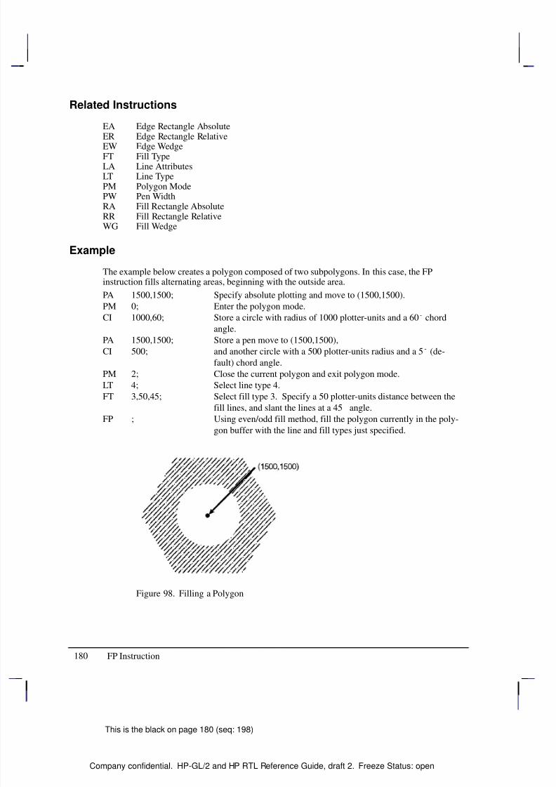
8/12/2019 HPGL2-RTL ReferenceGuide 5961-3526 540pages Sep96
http://slidepdf.com/reader/full/hpgl2-rtl-referenceguide-5961-3526-540pages-sep96 198/539
180
This is the black on page 180 (seq: 198)
Company confidential. HP-GL/2 and HP RTL Reference Guide, draft 2. Freeze Status: open
Related Instructions
EA Edge Rectangle Absolute
ER Edge Rectangle RelativeEW Edge WedgeFT Fill TypeLA Line AttributesLT Line TypePM Polygon ModePW Pen WidthRA Fill Rectangle AbsoluteRR Fill Rectangle RelativeWG Fill Wedge
Example
The example below creates a polygon composed of two subpolygons. In this case, the FPinstruction fills alternating areas, beginning with the outside area.
PA 1500,1500; Specify absolute plotting and move to (1500,1500).
PM 0; Enter the polygon mode.
CI 1000,60; Store a circle with radius of 1000 plotter-units and a 60 chord
angle.
PA 1500,1500; Store a pen move to (1500,1500),
CI 500; and another circle with a 500 plotter-units radius and a 5 (de-
fault) chord angle.
PM 2; Close the current polygon and exit polygon mode.
LT 4; Select line type 4.
FT 3,50,45; Select fill type 3. Specify a 50 plotter-units distance between the
fill lines, and slant the lines at a 45 angle.
FP ; Using even/odd fill method, fill the polygon currently in the poly-
gon buffer with the line and fill types just specified.
Figure 98. Filling a Polygon
FP Instruction
8/12/2019 HPGL2-RTL ReferenceGuide 5961-3526 540pages Sep96
http://slidepdf.com/reader/full/hpgl2-rtl-referenceguide-5961-3526-540pages-sep96 199/539
181
This is the black on page 181 (seq: 199)
Company confidential. HP-GL/2 and HP RTL Reference Guide, draft 2. Freeze Status: open
FR, Frame Advance
Purpose
To advance the media to align adjacent frames, forming the equivalent of a long-axis plot. Thedevice treats each frame as a separate window and plots only the data falling within that win-dow. Using the PS (Plot Size) instruction for long-axis plotting is simpler and faster than usingFR.
Syntax
FR [;]
Group
This instruction is in the Technical Graphics Extension.
Use
FR updates the current pen location to the new plotter-unit origin, leaves the pen in the up posi-tion, and clears the polygon buffer.
The length parameter of the PS (Plot Size) instruction determines the frame size. Whenlengthwidth, the orientation is reverse landscape and each FR instruction extends the plot inthe direction of the positive X-axis. When length<width, the orientation is reverse portrait andeach FR instruction extends the plot in the direction of the positive Y-axis.
The length advanced with an FR instruction is shorter than that of a PG instruction; the margins
between the plotter areas are deleted so that the frames share a common edge.
After each frame advance, the plotter-unit origin moves to the lower-left corner of the newframe. The physical locations of P1 and P2 are retained, but the logical locations relative to thecurrent origin change.
FR is ideal for use with roll-feed plotters. When using single-sheet devices, frames will share acommon edge only when complete frames will fit on the current sheet. If multiple frames willnot fit, the current page is printed and ejected. The next sheet loaded will contain the newframe. Any device that can store an entire multi-frame plot can print multiple copies using ei-ther the BP or RP instructions.
Note that a cut-sheet device which cannot store the entire plot can still produce multiple copieswhen specified in the BP instruction; however, the user must collate the copies. In this case,however, the RP instruction is equivalent to a PG.
Related Instructions
AC Anchor CornerIW Input WindowPS Plot Size
This is the blue on page 181 (seq: 199)
FR Instruction
I N S T R U C T I O N S
H P - G L / 2
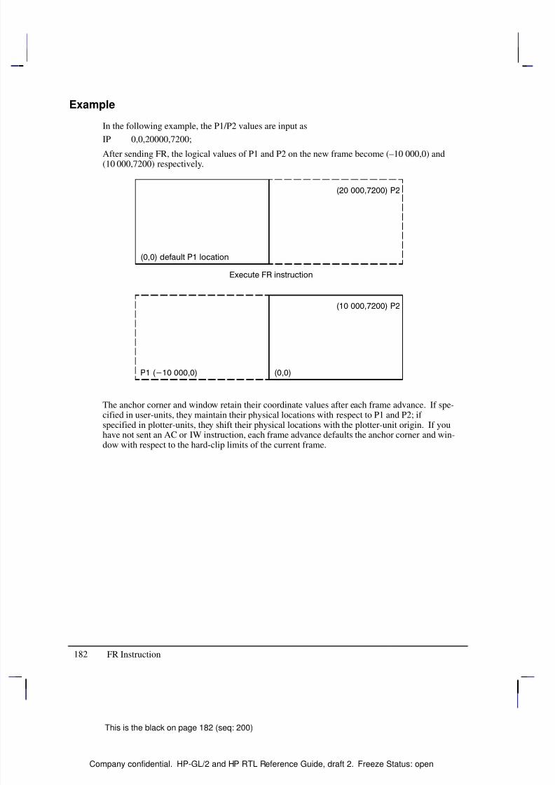
8/12/2019 HPGL2-RTL ReferenceGuide 5961-3526 540pages Sep96
http://slidepdf.com/reader/full/hpgl2-rtl-referenceguide-5961-3526-540pages-sep96 200/539
182
This is the black on page 182 (seq: 200)
Company confidential. HP-GL/2 and HP RTL Reference Guide, draft 2. Freeze Status: open
Example
In the following example, the P1/P2 values are input as
IP 0,0,20000,7200;
After sending FR, the logical values of P1 and P2 on the new frame become (–10 000,0) and(10 000,7200) respectively.
The anchor corner and window retain their coordinate values after each frame advance. If spe-
cified in user-units, they maintain their physical locations with respect to P1 and P2; if specified in plotter-units, they shift their physical locations with the plotter-unit origin. If youhave not sent an AC or IW instruction, each frame advance defaults the anchor corner and win-dow with respect to the hard-clip limits of the current frame.
FR Instruction
8/12/2019 HPGL2-RTL ReferenceGuide 5961-3526 540pages Sep96
http://slidepdf.com/reader/full/hpgl2-rtl-referenceguide-5961-3526-540pages-sep96 201/539
183
This is the black on page 183 (seq: 201)
Company confidential. HP-GL/2 and HP RTL Reference Guide, draft 2. Freeze Status: open
FT, Fill Type
Purpose
To select the shading pattern used to fill polygons (FP), rectangles (RA or RR), characters (CF),or wedges (WG). Use FT to enhance plots with solid fill, parallel lines (hatching), cross-hatch-ing, or patterned (raster) fill.
Syntax
FT fill_type[,option1[,option2]][;]or
FT [;]
Á Á Á Á Á Á Á
Á Á Á Á Á Á Á
Parameter Á Á Á Á Á Á Á
Á Á Á Á Á Á Á
Format Á Á Á Á Á Á Á Á
Á Á Á Á Á Á Á Á
Functional Range Á Á Á Á Á Á Á
Á Á Á Á Á Á Á
Parameter Default
Á Á Á Á Á Á Á
Á Á Á Á Á Á Á
fill_type Á Á Á Á Á Á Á
Á Á Á Á Á Á Á
clamped integer Á Á Á Á Á Á Á Á
Á Á Á Á Á Á Á Á
1, 2, 3, 4, 10, 11, 21, 22 Á Á Á Á Á Á Á
Á Á Á Á Á Á Á
1
Á Á Á Á Á Á Á
Á Á Á Á Á Á Á
option1, option2Á Á Á Á Á Á Á
Á Á Á Á Á Á Á
clamped realÁ Á Á Á Á Á Á Á
Á Á Á Á Á Á Á Á
fill_type-dependent*Á Á Á Á Á Á Á
Á Á Á Á Á Á Á
fill_type-dependent*
* Refer to the table following the parameter descriptions.
Group
This instruction is in the Line and Fill Attributes Group.
Use
There are six base forms of fill type, and additional ones for devices that support the dual-con-text environment—see page 83. The fill_type parameter tells the device which form you areusing.
No parameters: equivalent to “FT1”—the fill type is solid.
fill_type: selects the fill pattern. It is a clamped integer whose value is restricted to thosegiven in the table below, which lists the option parameter values and the corresponding
fill_types.
option1 and option2: When the option parameters are omitted, the device uses the lastspecified parameters for that fill type. For example, if you specified fill_type 3 with linespacing and angle parameters, then switched to fill_type 4 without specifying any lineparameters, the device would draw fill type 4 with default line spacing and angles becausethey have not yet been specified for that fill type. If you then switched back to fill type 3,
you would not need to respecify the line spacing and angle parameters because the devicewould use the values previously specified for the fill type 3 instruction.
The ranges (clamped real values) and definitions of these optional parameters depends onthe type of fill selected, as follows:
This is the blue on page 183 (seq: 201)
FT Instruction
I N S T R U C T I O N S
H P - G L / 2
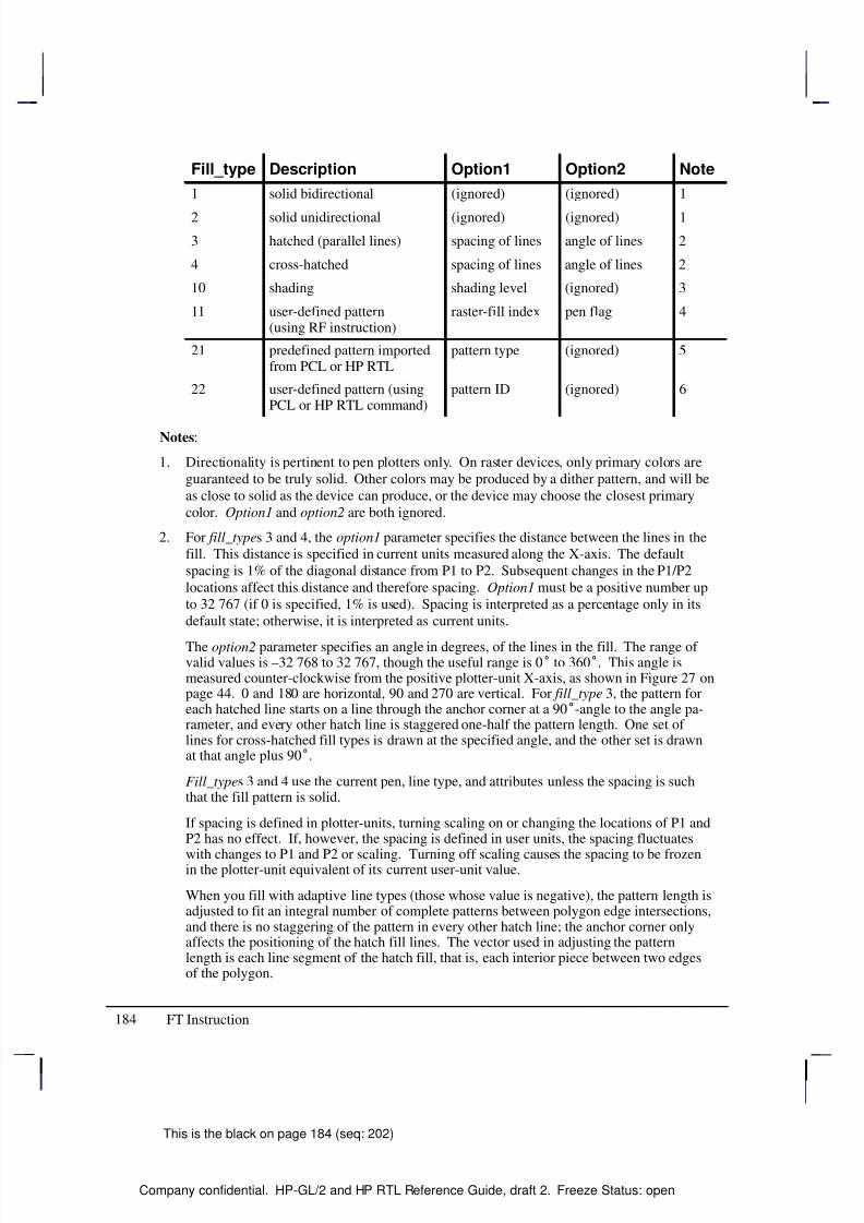
8/12/2019 HPGL2-RTL ReferenceGuide 5961-3526 540pages Sep96
http://slidepdf.com/reader/full/hpgl2-rtl-referenceguide-5961-3526-540pages-sep96 202/539
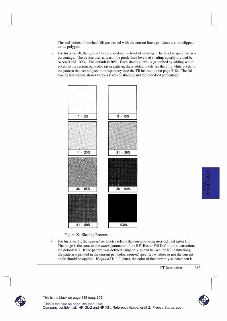
8/12/2019 HPGL2-RTL ReferenceGuide 5961-3526 540pages Sep96
http://slidepdf.com/reader/full/hpgl2-rtl-referenceguide-5961-3526-540pages-sep96 203/539
185
This is the black on page 185 (seq: 203)
Company confidential. HP-GL/2 and HP RTL Reference Guide, draft 2. Freeze Status: open
The end-points of hatched fills are treated with the current line cap. Lines are not clippedto the polygon.
3. For fill_type 10, the option1 value specifies the level of shading. The level is specified as a
percentage. The device uses at least nine predefined levels of shading equally divided be-tween 0 and 100%. The default is 50%. Each shading level is generated by adding whitepixels to the current pen color raster pattern; these added pixels are the only white pixels inthe pattern that are subject to transparency (see the TR instruction on page 318). The fol-lowing illustration shows various levels of shading and the specified percentage:
Figure 99. Shading Patterns
4. For fill_type 11, the option1 parameter selects the corresponding user-defined raster fill.The range is the same as the index parameter of the RF (Raster Fill Definition) instruction;the default is 1. If the pattern was defined using only 1s and 0s (see the RF instruction),the pattern is printed in the current pen color; option2 specifies whether or not the currentcolor should be applied. If option2 is “1” (true), the color of the currently selected pen is
This is the blue on page 185 (seq: 203)
FT Instruction
I N S T R U C T I O N S
H P - G L / 2
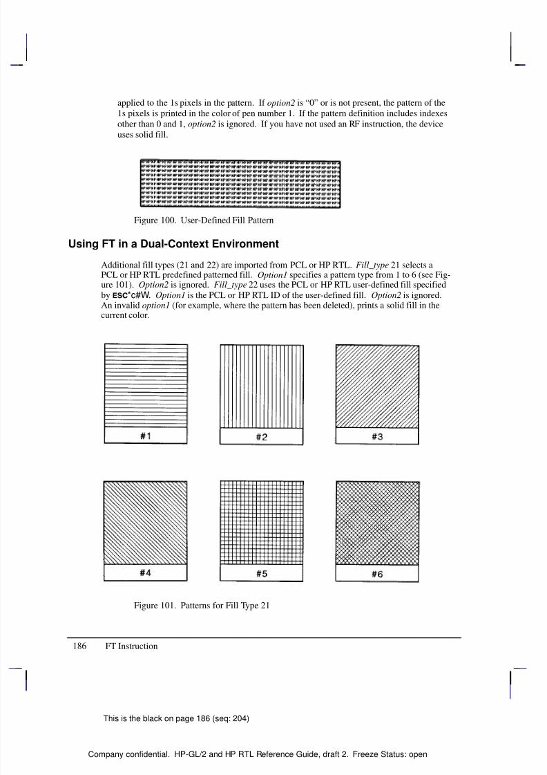
8/12/2019 HPGL2-RTL ReferenceGuide 5961-3526 540pages Sep96
http://slidepdf.com/reader/full/hpgl2-rtl-referenceguide-5961-3526-540pages-sep96 204/539
186
This is the black on page 186 (seq: 204)
Company confidential. HP-GL/2 and HP RTL Reference Guide, draft 2. Freeze Status: open
applied to the 1s pixels in the pattern. If option2 is “0” or is not present, the pattern of the1s pixels is printed in the color of pen number 1. If the pattern definition includes indexesother than 0 and 1, option2 is ignored. If you have not used an RF instruction, the device
uses solid fill.
Figure 100. User-Defined Fill Pattern
Using FT in a Dual-Context Environment
Additional fill types (21 and 22) are imported from PCL or HP RTL. Fill_type 21 selects aPCL or HP RTL predefined patterned fill. Option1 specifies a pattern type from 1 to 6 (see Fig-ure 101). Option2 is ignored. Fill_type 22 uses the PCL or HP RTL user-defined fill specifiedby *c#W. Option1 is the PCL or HP RTL ID of the user-defined fill. Option2 is ignored.An invalid option1 (for example, where the pattern has been deleted), prints a solid fill in thecurrent color.
Figure 101. Patterns for Fill Type 21
FT Instruction
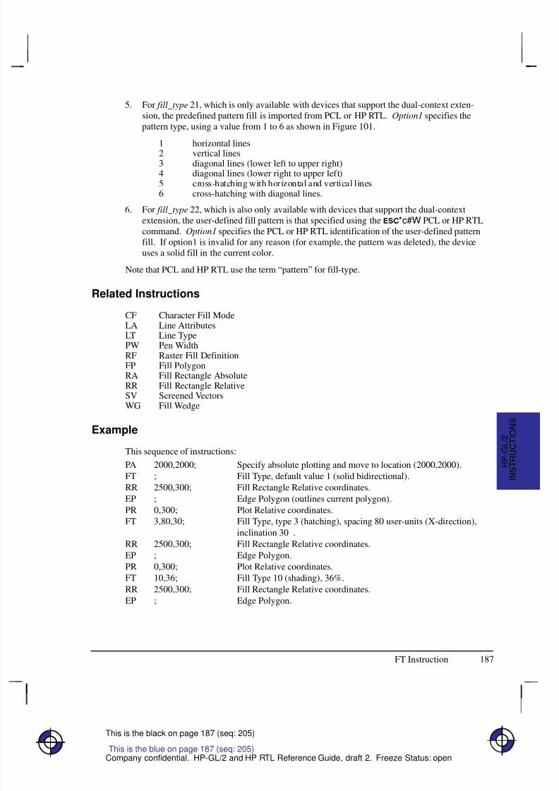
8/12/2019 HPGL2-RTL ReferenceGuide 5961-3526 540pages Sep96
http://slidepdf.com/reader/full/hpgl2-rtl-referenceguide-5961-3526-540pages-sep96 205/539
187
This is the black on page 187 (seq: 205)
Company confidential. HP-GL/2 and HP RTL Reference Guide, draft 2. Freeze Status: open
5. For fill_type 21, which is only available with devices that support the dual-context exten-sion, the predefined pattern fill is imported from PCL or HP RTL. Option1 specifies thepattern type, using a value from 1 to 6 as shown in Figure 101.
1 horizontal lines2 vertical lines3 diagonal lines (lower left to upper right)4 diagonal lines (lower right to upper left)5 cross-hatching with horizontal and vertical lines6 cross-hatching with diagonal lines.
6. For fill_type 22, which is also only available with devices that support the dual-contextextension, the user-defined fill pattern is that specified using the *c#W PCL or HP RTLcommand. Option1 specifies the PCL or HP RTL identification of the user-defined patternfill. If option1 is invalid for any reason (for example, the pattern was deleted), the deviceuses a solid fill in the current color.
Note that PCL and HP RTL use the term “pattern” for fill-type.
Related Instructions
CF Character Fill ModeLA Line AttributesLT Line TypePW Pen WidthRF Raster Fill DefinitionFP Fill PolygonRA Fill Rectangle AbsoluteRR Fill Rectangle RelativeSV Screened VectorsWG Fill Wedge
Example
This sequence of instructions:
PA 2000,2000; Specify absolute plotting and move to location (2000,2000).
FT ; Fill Type, default value 1 (solid bidirectional).
RR 2500,300; Fill Rectangle Relative coordinates.
EP ; Edge Polygon (outlines current polygon).
PR 0,300; Plot Relative coordinates.
FT 3,80,30; Fill Type, type 3 (hatching), spacing 80 user-units (X-direction),
inclination 30.
RR 2500,300; Fill Rectangle Relative coordinates.
EP ; Edge Polygon.PR 0,300; Plot Relative coordinates.
FT 10,36; Fill Type 10 (shading), 36%.
RR 2500,300; Fill Rectangle Relative coordinates.
EP ; Edge Polygon.
This is the blue on page 187 (seq: 205)
FT Instruction
I N S T R U C T I O N S
H P - G L / 2

8/12/2019 HPGL2-RTL ReferenceGuide 5961-3526 540pages Sep96
http://slidepdf.com/reader/full/hpgl2-rtl-referenceguide-5961-3526-540pages-sep96 206/539
8/12/2019 HPGL2-RTL ReferenceGuide 5961-3526 540pages Sep96
http://slidepdf.com/reader/full/hpgl2-rtl-referenceguide-5961-3526-540pages-sep96 207/539
189
This is the black on page 189 (seq: 207)
Company confidential. HP-GL/2 and HP RTL Reference Guide, draft 2. Freeze Status: open
IN, Initialize
Purpose
To resets all programmable HP-GL/2 functions to their default settings. Use the IN instructionto return the device to a known HP-GL/2 state and to cancel settings that may have beenchanged by a previous instruction sequence. (The E Reset command and the BP [BeginPlot] instruction issue an automatic IN instruction).
Syntax
IN n[;]or
IN [;]
Á Á Á Á Á Á Á
Á Á Á Á Á Á Á
ParameterÁ Á Á Á Á Á Á
Á Á Á Á Á Á Á
FormatÁ Á Á Á Á Á Á Á
Á Á Á Á Á Á Á Á
Functional RangeÁ Á Á Á Á Á Á
Á Á Á Á Á Á Á
Parameter DefaultÁ Á Á Á Á Á Á
Á
Á Á Á Á Á Á
Á Á Á Á Á Á Á
n
Á Á Á Á Á Á Á
Á
Á Á Á Á Á Á
Á Á Á Á Á Á Á
clamped integer
Á Á Á Á Á Á Á Á
Á
Á Á Á Á Á Á Á
Á Á Á Á Á Á Á Á
1 (see below)
Á Á Á Á Á Á Á
Á
Á Á Á Á Á Á
Á Á Á Á Á Á Á
no parameter
Group
This instruction is in the Configuration and Status Group.
Use
No parameter: Defaults to the feature settings specified using the device’s control panel,and sets all other programmable HP-GL/2 features to their factory defaults.
n: Defaults all programmable HP-GL/2 features to the factory-set conditions.If n is fractional, it is rounded to the nearest integer, so 0.6 is rounded to 1. Any number inthe range –223 to 223–1 (other than 1 on some devices—see below) is treated like “IN;” (noparameter).
An “IN1” instruction is used in some devices, principally pen plotters, as a temporary over-ride of control-panel defaults; a subsequent “IN” (with no parameter) will restore thecontrol-panel defaults. “IN1” is not recommended unless it is imperative that the pro- gram control the device.
All instruction sequences should begin with IN to clear unwanted conditions from the previousinstruction sequence, even though an E command and a BP (Begin Plot) instruction auto-matically execute an IN instruction. All HP-GL/2 errors are cleared.
Once HP-GL/2 mode is entered and instructions are issued, the HP-GL/2 conditions are nolonger initialized. To place HP-GL/2 into the default state, send the IN instruction.
IN does not default pen selection; the pen selected before IN remains selected afterwards, andis raised (up state) in the lower-left corner of the hard-clip limits.
The IN instruction sets the device to the same conditions as the DF (Default Values) instruction(see page 136), plus the following:
This is the blue on page 189 (seq: 207)
IN Instruction
I N S T R U C T I O N S
H P - G L / 2
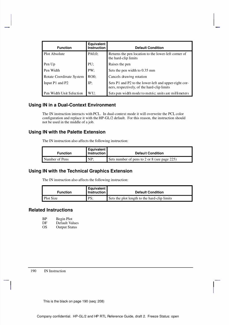
8/12/2019 HPGL2-RTL ReferenceGuide 5961-3526 540pages Sep96
http://slidepdf.com/reader/full/hpgl2-rtl-referenceguide-5961-3526-540pages-sep96 208/539
190
This is the black on page 190 (seq: 208)
Company confidential. HP-GL/2 and HP RTL Reference Guide, draft 2. Freeze Status: open
FunctionEquivalentInstruction Default Condition
Plot Absolute PA0,0; Returns the pen location to the lower-left corner of
the hard-clip limits
Pen Up PU; Raises the pen
Pen Width PW; Sets the pen width to 0.35 mm
Rotate Coordinate System RO0; Cancels drawing rotation
Input P1 and P2 IP; Sets P1 and P2 to the lower-left and upper-right cor-ners, respectively, of the hard-clip limits
Pen Width Unit Selection WU; Sets pen width mode to metric; units are millimeters
Using IN in a Dual-Context Environment
The IN instruction interacts with PCL. In dual-context mode it will overwrite the PCL colorconfiguration and replace it with the HP-GL/2 default. For this reason, the instruction shouldnot be used in the middle of a job.
Using IN with the Palette Extension
The IN instruction also affects the following instruction:
FunctionEquivalentInstruction Default Condition
Number of Pens NP; Sets number of pens to 2 or 8 (see page 225)
Using IN with the Technical Graphics Extension
The IN instruction also affects the following instruction:
FunctionEquivalentInstruction Default Condition
Plot Size PS; Sets the plot length to the hard-clip limits
Related Instructions
BP Begin PlotDF Default Values
OS Output Status
IN Instruction
8/12/2019 HPGL2-RTL ReferenceGuide 5961-3526 540pages Sep96
http://slidepdf.com/reader/full/hpgl2-rtl-referenceguide-5961-3526-540pages-sep96 209/539
191
This is the black on page 191 (seq: 209)
Company confidential. HP-GL/2 and HP RTL Reference Guide, draft 2. Freeze Status: open
IP, Input P1 and P2
Purpose
To establish new or default locations for the scaling points P1 and P2. P1 and P2 are used bythe SC (Scale) instruction to establish user-unit scaling. You can also use IP in advanced tech-niques such as printing mirror-images (as explained on page 35), enlarging and reducingdrawings (see page 33), and enlarging and reducing relative character size (see page 308),changing label direction (see page 149), changing pen widths (see pages 264 and 328), chang-ing spacing for hatch-filled patterns (see page 183), or changing the line type pattern length(see page 215). IP does not affect the window limits (see page 197).
Syntax
IP P1 X ,P1Y [,P2 X ,P2Y ][;]
orIP [;]
Á Á Á Á Á Á Á
Á Á Á Á Á Á Á
ParameterÁ Á Á Á Á Á Á
Á Á Á Á Á Á Á
FormatÁ Á Á Á Á Á Á Á
Á Á Á Á Á Á Á Á
Functional RangeÁ Á Á Á Á Á Á
Á Á Á Á Á Á Á
Parameter Default
Á Á Á Á Á Á Á
Á Á Á Á Á Á Á
P1 X ,P1Y ,P2 X ,P2Y Á Á Á Á Á Á Á
Á Á Á Á Á Á Á
integerÁ Á Á Á Á Á Á Á
Á Á Á Á Á Á Á Á
–230 to 230 – 1Á Á Á Á Á Á Á
Á Á Á Á Á Á Á
(see below)
Group
This instruction is in the Configuration and Status Group.
Use
The default location of P1 for “printers” (that is, devices that do not support the TechnicalGraphics Extension) is the lower-left corner of the hard-clip limits; the default location of P2 isthe upper-right corner, as shown in Figure 103. (The default picture frame extends from the topmargin to the bottom margin, and from the left edge to the right edge of the logical page.) For“plotters” (that is, devices that do support the Technical Graphics Extension) the default posi-tion and orientation of the X- and Y-axes is different (see Figure 10 on page 10) but thepositions of P1 and P2 relative to the axes is as in Figure 103.
No Parameters: Sets P1 and P2 to their default locations, adjusted by any current axisrotation.
Note: If an IP instruction without parameters is executed after the axes are rotated with theRO instruction, P1 and P2 locations change to reflect the rotation. If the coordinate systemorientation subsequently changes (for example, by sending an RO instruction), the plotter-
unit position is maintained with respect to the new orientation.X,Y coordinates: Specify the location of P1 (and, optionally, P2) in plotter-units (see page12). Specifying P2 is not required. If P2 is not specified, P2 tracks P1 and its coordinateschange so that the X,Y distances between P2 and P1 stay the same. This tracking processcan locate P2 outside the effective window. Used carefully, the tracking function can beuseful for preparing more than one equal-sized drawing on a page. For an example, referto Drawing Equal-Sized Pictures on a Page on page 34. Neither X,Y coordinate of P1 canequal the corresponding coordinate of P2. If either coordinate of P1 equals the correspond-ing coordinate of P2, the coordinate of P2 is incremented by 1 plotter-unit.
This is the blue on page 191 (seq: 209)
IP Instruction
I N S T R U C T I O N S
H P - G L / 2
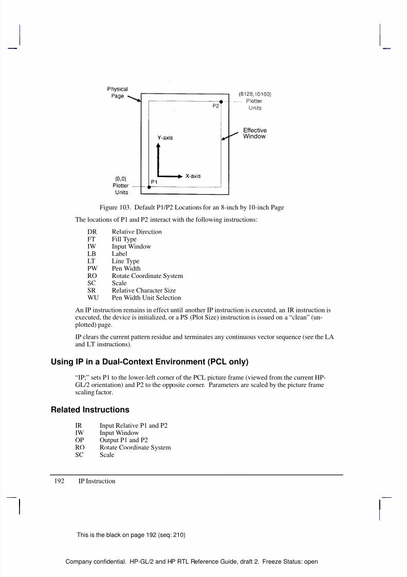
8/12/2019 HPGL2-RTL ReferenceGuide 5961-3526 540pages Sep96
http://slidepdf.com/reader/full/hpgl2-rtl-referenceguide-5961-3526-540pages-sep96 210/539
192
This is the black on page 192 (seq: 210)
Company confidential. HP-GL/2 and HP RTL Reference Guide, draft 2. Freeze Status: open
Figure 103. Default P1/P2 Locations for an 8-inch by 10-inch Page
The locations of P1 and P2 interact with the following instructions:
DR Relative DirectionFT Fill TypeIW Input WindowLB LabelLT Line TypePW Pen WidthRO Rotate Coordinate SystemSC ScaleSR Relative Character SizeWU Pen Width Unit Selection
An IP instruction remains in effect until another IP instruction is executed, an IR instruction isexecuted, the device is initialized, or a PS (Plot Size) instruction is issued on a “clean” (un-plotted) page.
IP clears the current pattern residue and terminates any continuous vector sequence (see the LAand LT instructions).
Using IP in a Dual-Context Environment (PCL only)
“IP;” sets P1 to the lower-left corner of the PCL picture frame (viewed from the current HP-GL/2 orientation) and P2 to the opposite corner. Parameters are scaled by the picture framescaling factor.
Related Instructions
IR Input Relative P1 and P2IW Input WindowOP Output P1 and P2RO Rotate Coordinate SystemSC Scale
IP Instruction

8/12/2019 HPGL2-RTL ReferenceGuide 5961-3526 540pages Sep96
http://slidepdf.com/reader/full/hpgl2-rtl-referenceguide-5961-3526-540pages-sep96 211/539
193
This is the black on page 193 (seq: 211)
Company confidential. HP-GL/2 and HP RTL Reference Guide, draft 2. Freeze Status: open
Possible Error Conditions
Error Condition Error Number Printer or Plotter Response
One or three parameters 2 Ignores instruction
This is the blue on page 193 (seq: 211)
IP Instruction
I N S T R U C T I O N S
H P - G L / 2
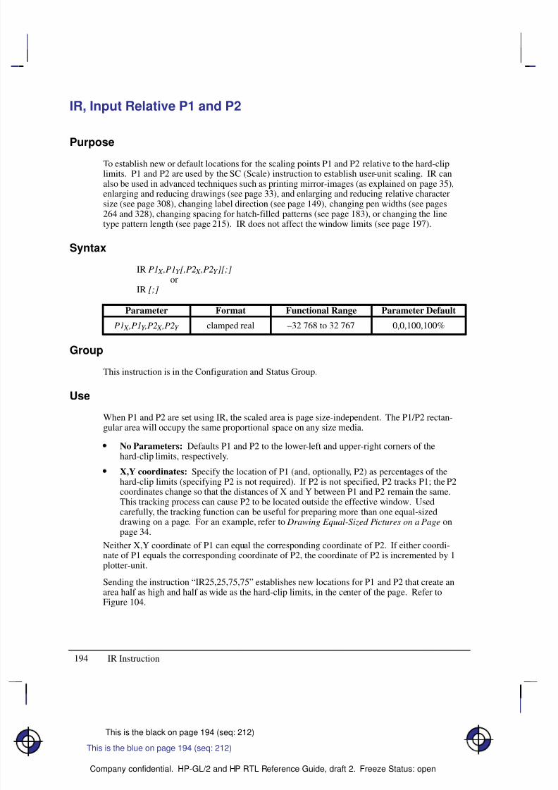
8/12/2019 HPGL2-RTL ReferenceGuide 5961-3526 540pages Sep96
http://slidepdf.com/reader/full/hpgl2-rtl-referenceguide-5961-3526-540pages-sep96 212/539
194
This is the black on page 194 (seq: 212)
Company confidential. HP-GL/2 and HP RTL Reference Guide, draft 2. Freeze Status: open
IR, Input Relative P1 and P2
Purpose
To establish new or default locations for the scaling points P1 and P2 relative to the hard-cliplimits. P1 and P2 are used by the SC (Scale) instruction to establish user-unit scaling. IR canalso be used in advanced techniques such as printing mirror-images (as explained on page 35),enlarging and reducing drawings (see page 33), and enlarging and reducing relative charactersize (see page 308), changing label direction (see page 149), changing pen widths (see pages264 and 328), changing spacing for hatch-filled patterns (see page 183), or changing the linetype pattern length (see page 215). IR does not affect the window limits (see page 197).
Syntax
IR P1 X ,P1Y [,P2 X ,P2Y ][;]
orIR [;]
Á Á Á Á Á Á Á
Á Á Á Á Á Á Á
ParameterÁ Á Á Á Á Á
Á Á Á Á Á Á
FormatÁ Á Á Á Á Á Á Á
Á Á Á Á Á Á Á Á
Functional RangeÁ Á Á Á Á Á Á Á
Á Á Á Á Á Á Á Á
Parameter Default
Á Á Á Á Á Á Á
Á Á Á Á Á Á Á
P1 X ,P1Y ,P2 X ,P2Y Á Á Á Á Á Á
Á Á Á Á Á Á
clamped realÁ Á Á Á Á Á Á Á
Á Á Á Á Á Á Á Á
–32 768 to 32 767Á Á Á Á Á Á Á Á
Á Á Á Á Á Á Á Á
0,0,100,100%
Group
This instruction is in the Configuration and Status Group.
Use
When P1 and P2 are set using IR, the scaled area is page size-independent. The P1/P2 rectan-gular area will occupy the same proportional space on any size media.
No Parameters: Defaults P1 and P2 to the lower-left and upper-right corners of thehard-clip limits, respectively.
X,Y coordinates: Specify the location of P1 (and, optionally, P2) as percentages of thehard-clip limits (specifying P2 is not required). If P2 is not specified, P2 tracks P1; the P2coordinates change so that the distances of X and Y between P1 and P2 remain the same.This tracking process can cause P2 to be located outside the effective window. Usedcarefully, the tracking function can be useful for preparing more than one equal-sizeddrawing on a page. For an example, refer to Drawing Equal-Sized Pictures on a Page onpage 34.
Neither X,Y coordinate of P1 can equal the corresponding coordinate of P2. If either coordi-
nate of P1 equals the corresponding coordinate of P2, the coordinate of P2 is incremented by 1plotter-unit.
Sending the instruction “IR25,25,75,75” establishes new locations for P1 and P2 that create anarea half as high and half as wide as the hard-clip limits, in the center of the page. Refer toFigure 104.
This is the blue on page 194 (seq: 212)
IR Instruction
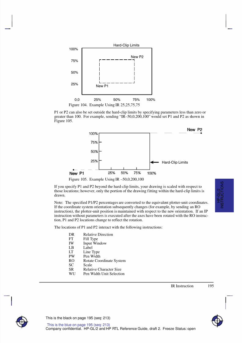
8/12/2019 HPGL2-RTL ReferenceGuide 5961-3526 540pages Sep96
http://slidepdf.com/reader/full/hpgl2-rtl-referenceguide-5961-3526-540pages-sep96 213/539
195
This is the black on page 195 (seq: 213)
Company confidential. HP-GL/2 and HP RTL Reference Guide, draft 2. Freeze Status: open
Figure 104. Example Using IR 25,25,75,75
P1 or P2 can also be set outside the hard-clip limits by specifying parameters less than zero orgreater than 100. For example, sending “IR–50,0,200,100” would set P1 and P2 as shown in
Figure 105.
Figure 105. Example Using IR –50,0,200,100If you specify P1 and P2 beyond the hard-clip limits, your drawing is scaled with respect tothose locations; however, only the portion of the drawing fitting within the hard-clip limits isdrawn.
Note: The specified P1/P2 percentages are converted to the equivalent plotter-unit coordinates.If the coordinate system orientation subsequently changes (for example, by sending an ROinstruction), the plotter-unit position is maintained with respect to the new orientation. If an IPinstruction without parameters is executed after the axes have been rotated with the RO instruc-tion, P1 and P2 locations change to reflect the rotation.
The locations of P1 and P2 interact with the following instructions:
DR Relative Direction
FT Fill TypeIW Input WindowLB LabelLT Line TypePW Pen WidthRO Rotate Coordinate SystemSC ScaleSR Relative Character SizeWU Pen Width Unit Selection
This is the blue on page 195 (seq: 213)
IR Instruction
I N S T R U C T I O N S
H P - G L / 2
8/12/2019 HPGL2-RTL ReferenceGuide 5961-3526 540pages Sep96
http://slidepdf.com/reader/full/hpgl2-rtl-referenceguide-5961-3526-540pages-sep96 214/539
196
This is the black on page 196 (seq: 214)
Company confidential. HP-GL/2 and HP RTL Reference Guide, draft 2. Freeze Status: open
An IR instruction remains in effect until another IR instruction is executed, an IP instruction isexecuted, or the device is initialized, or a PS (Plot Size) instruction is issued on a “clean” (un-plotted) page.
IR clears the current pattern residue and terminates any continuous vector sequence (see the LAand LT instructions).
Using IR in a Dual-Context Environment (PCL only)
The references to the hard-clip limits are replaced by the PCL picture frame. The default posi-tions for P1 and P2 are the lower-left and upper-right corners of the picture frame, as viewedfrom the current orientation.
Related Instructions
IP Input P1 and P2
IW Input WindowOP Output P1 and P2RO Rotate Coordinate SystemSC Scale
Possible Error Conditions
Error Condition Error Number Printer or Plotter Response
One or three parameters 2 Ignores instruction
More than four parameters 2 Uses first four parameters
IR Instruction
8/12/2019 HPGL2-RTL ReferenceGuide 5961-3526 540pages Sep96
http://slidepdf.com/reader/full/hpgl2-rtl-referenceguide-5961-3526-540pages-sep96 215/539
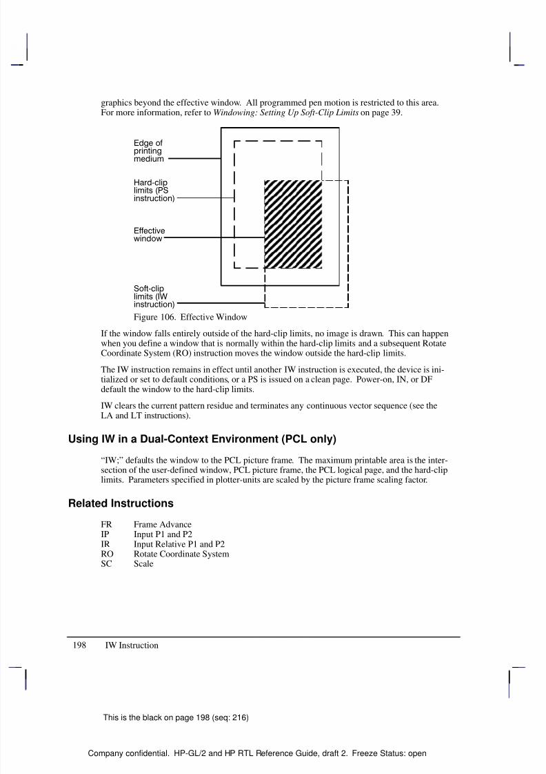
8/12/2019 HPGL2-RTL ReferenceGuide 5961-3526 540pages Sep96
http://slidepdf.com/reader/full/hpgl2-rtl-referenceguide-5961-3526-540pages-sep96 216/539
198
This is the black on page 198 (seq: 216)
Company confidential. HP-GL/2 and HP RTL Reference Guide, draft 2. Freeze Status: open
graphics beyond the effective window. All programmed pen motion is restricted to this area.For more information, refer to Windowing: Setting Up Soft-Clip Limits on page 39.
Í Í Í Í Í
Í Í Í Í Í
Í Í Í Í Í
Í Í Í Í Í
Í Í Í Í Í
Í Í Í Í Í
Í Í Í Í Í
Í Í Í Í Í
Figure 106. Effective Window
If the window falls entirely outside of the hard-clip limits, no image is drawn. This can happenwhen you define a window that is normally within the hard-clip limits and a subsequent RotateCoordinate System (RO) instruction moves the window outside the hard-clip limits.
The IW instruction remains in effect until another IW instruction is executed, the device is ini-tialized or set to default conditions, or a PS is issued on a clean page. Power-on, IN, or DFdefault the window to the hard-clip limits.
IW clears the current pattern residue and terminates any continuous vector sequence (see theLA and LT instructions).
Using IW in a Dual-Context Environment (PCL only)
“IW;” defaults the window to the PCL picture frame. The maximum printable area is the inter-section of the user-defined window, PCL picture frame, the PCL logical page, and the hard-cliplimits. Parameters specified in plotter-units are scaled by the picture frame scaling factor.
Related Instructions
FR Frame AdvanceIP Input P1 and P2
IR Input Relative P1 and P2RO Rotate Coordinate SystemSC Scale
IW Instruction
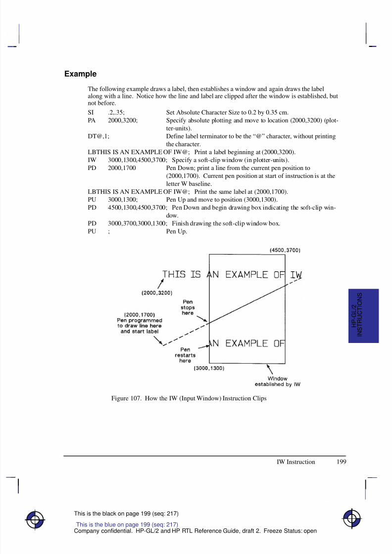
8/12/2019 HPGL2-RTL ReferenceGuide 5961-3526 540pages Sep96
http://slidepdf.com/reader/full/hpgl2-rtl-referenceguide-5961-3526-540pages-sep96 217/539
199
This is the black on page 199 (seq: 217)
Company confidential. HP-GL/2 and HP RTL Reference Guide, draft 2. Freeze Status: open
Example
The following example draws a label, then establishes a window and again draws the label
along with a line. Notice how the line and label are clipped after the window is established, butnot before.
SI .2,.35; Set Absolute Character Size to 0.2 by 0.35 cm.
PA 2000,3200; Specify absolute plotting and move to location (2000,3200) (plot-
ter-units).
DT@,1; Define label terminator to be the “@” character, without printing
the character.
LBTHIS IS AN EXAMPLE OF IW@; Print a label beginning at (2000,3200).
IW 3000,1300,4500,3700; Specify a soft-clip window (in plotter-units).
PD 2000,1700 Pen Down; print a line from the current pen position to
(2000,1700). Current pen position at start of instruction is at the
letter W baseline.
LBTHIS IS AN EXAMPLE OF IW@; Print the same label at (2000,1700).PU 3000,1300; Pen Up and move to position (3000,1300).
PD 4500,1300,4500,3700; Pen Down and begin drawing box indicating the soft-clip win-
dow.
PD 3000,3700,3000,1300; Finish drawing the soft-clip window box.
PU ; Pen Up.
Figure 107. How the IW (Input Window) Instruction Clips
This is the blue on page 199 (seq: 217)
IW Instruction
I N S T R U C T I O N S
H P - G L / 2
8/12/2019 HPGL2-RTL ReferenceGuide 5961-3526 540pages Sep96
http://slidepdf.com/reader/full/hpgl2-rtl-referenceguide-5961-3526-540pages-sep96 218/539
200
This is the black on page 200 (seq: 218)
Company confidential. HP-GL/2 and HP RTL Reference Guide, draft 2. Freeze Status: open
LA, Line Attributes
Purpose
To specify how line ends and line joins are physically shaped. Use this instruction when draw-ing lines thicker than 0.35 mm.
Syntax
LA kind,value[,kind,value[,kind,value]][;]or
LA [;]
Á Á Á Á Á Á
Á Á Á Á Á Á
ParameterÁ Á Á Á Á Á Á
Á Á Á Á Á Á Á
FormatÁ Á Á Á Á Á Á Á
Á Á Á Á Á Á Á Á
Functional RangeÁ Á Á Á Á Á Á Á
Á Á Á Á Á Á Á Á
Parameter DefaultÁ Á Á Á Á Á
Á Á Á Á Á Á
kind
Á Á Á Á Á Á Á
Á Á Á Á Á Á Á
clamped integer
Á Á Á Á Á Á Á Á
Á Á Á Á Á Á Á Á
1, 2, or 3
Á Á Á Á Á Á Á Á
Á Á Á Á Á Á Á Á
no defaultÁ Á Á Á Á Á
Á Á Á Á Á Á
Á Á Á Á Á Á
Á Á Á Á Á Á
valueÁ Á Á Á Á Á Á
Á
Á Á Á Á Á Á
Á Á Á Á Á Á Á
Á Á Á Á Á Á Á
clamped integerclamped integer
clamped real
Á Á Á Á Á Á Á Á
Á
Á Á Á Á Á Á Á
Á Á Á Á Á Á Á Á
Á Á Á Á Á Á Á Á
Kind 1: 1 through 4Kind 2: 1 through 6
Kind 3: 1 through 32 767
Á Á Á Á Á Á Á Á
Á
Á Á Á Á Á Á Á
Á Á Á Á Á Á Á Á
Á Á Á Á Á Á Á Á
1 (Butt)1 (Mitered)
5
Group
This instruction is in the Line and Fill Attributes Group.
Use
There are three line attributes: line ends, line joins, and the miter limit . The LA instruction pa-
rameters are used in pairs: the first parameter, kind , selects a line attribute, and the secondparameter, value, defines the appearance of that attribute. The device uses the current line at-tributes when the optional parameter pairs are omitted.
No Parameters: Defaults the line attributes to butt ends, mitered joins, and a miter limitof 5. Equivalent to “LA1,1,2,1,3,5”.
kind: Specifies the line attribute for which you are setting a value. Attributes and kind parameter values are listed in the following table.
value: Defines the characteristics of the attribute specified by the kind parameter. Theavailable values are listed in the following table and described under each attribute.
The current line attributes remain in effect when optional parameter pairs are omitted.
A continuous sequence of pen-down vectors uses the current line join and miter limit for coin-
cident first and last points. A continuous vector sequence is interrupted when a vector’s endpoint is not coincident with the next pen-down vector’s starting point, or by the AC, DF, IN, IP,IR, IW, LA, LT, PG, PW, RF, RO, RP, SC, SP, TR, UL, or WU instruction.
Instructions that restore the current pen position (CI, EA, EP, ER, EW, FP, PM, RA, RR, andWG) save the last vector’s end point upon completion. The pen-down sequence is continuedwhen the current pen position is restored. The last vector’s end point is also saved by CP or LBand before each SM symbol is drawn; the vector sequence is continued if the starting point of
This is the blue on page 200 (seq: 218)
LA Instruction
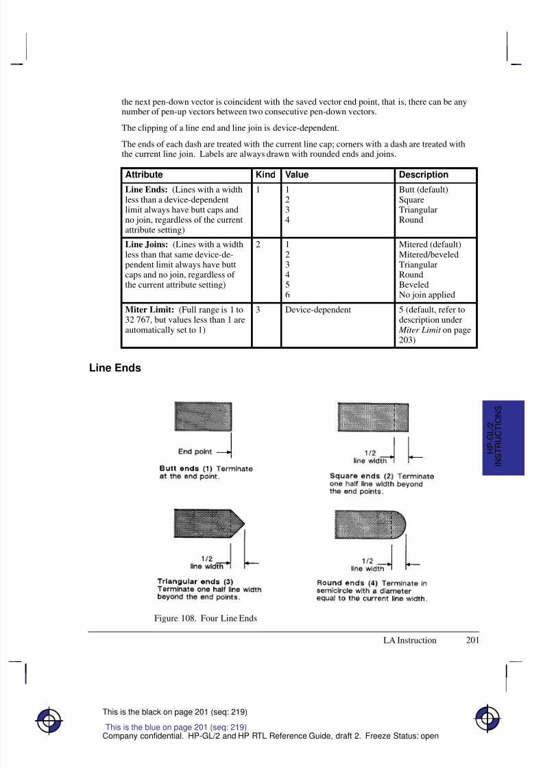
8/12/2019 HPGL2-RTL ReferenceGuide 5961-3526 540pages Sep96
http://slidepdf.com/reader/full/hpgl2-rtl-referenceguide-5961-3526-540pages-sep96 219/539
201
This is the black on page 201 (seq: 219)
Company confidential. HP-GL/2 and HP RTL Reference Guide, draft 2. Freeze Status: open
the next pen-down vector is coincident with the saved vector end point, that is, there can be anynumber of pen-up vectors between two consecutive pen-down vectors.
The clipping of a line end and line join is device-dependent.
The ends of each dash are treated with the current line cap; corners with a dash are treated withthe current line join. Labels are always drawn with rounded ends and joins.
Attribute Kind Value Description
Line Ends: (Lines with a widthless than a device-dependentlimit always have butt caps andno join, regardless of the currentattribute setting)
1 1234
Butt (default)SquareTriangularRound
Line Joins: (Lines with a widthless than that same device-de-
pendent limit always have buttcaps and no join, regardless of the current attribute setting)
2 12
3456
Mitered (default)Mitered/beveled
TriangularRoundBeveledNo join applied
Miter Limit: (Full range is 1 to32 767, but values less than 1 areautomatically set to 1)
3 Device-dependent 5 (default, refer todescription under
Miter Limit on page203)
Line Ends
Figure 108. Four Line Ends
This is the blue on page 201 (seq: 219)
LA Instruction
I N S T R U C T I O N S
H P - G L / 2
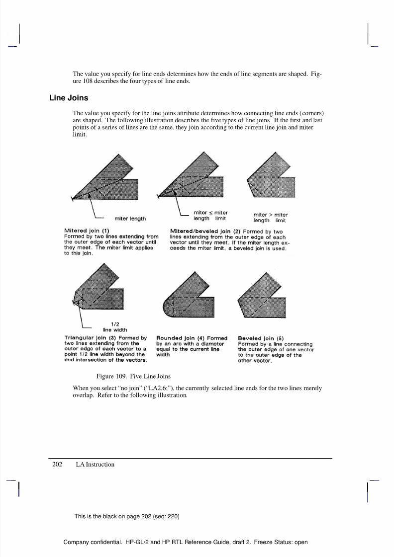
8/12/2019 HPGL2-RTL ReferenceGuide 5961-3526 540pages Sep96
http://slidepdf.com/reader/full/hpgl2-rtl-referenceguide-5961-3526-540pages-sep96 220/539
202
This is the black on page 202 (seq: 220)
Company confidential. HP-GL/2 and HP RTL Reference Guide, draft 2. Freeze Status: open
The value you specify for line ends determines how the ends of line segments are shaped. Fig-ure 108 describes the four types of line ends.
Line Joins
The value you specify for the line joins attribute determines how connecting line ends (corners)are shaped. The following illustration describes the five types of line joins. If the first and lastpoints of a series of lines are the same, they join according to the current line join and miterlimit.
Figure 109. Five Line Joins
When you select “no join” (“LA2,6;”), the currently selected line ends for the two lines merelyoverlap. Refer to the following illustration.
LA Instruction
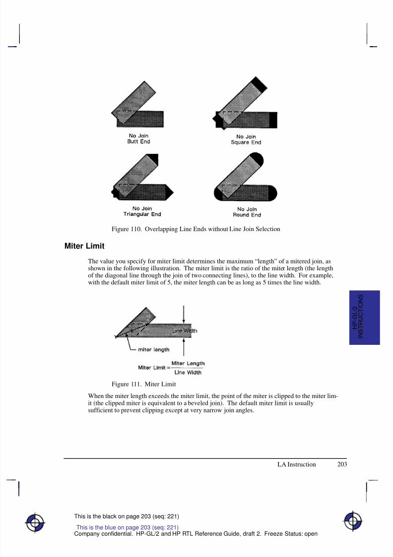
8/12/2019 HPGL2-RTL ReferenceGuide 5961-3526 540pages Sep96
http://slidepdf.com/reader/full/hpgl2-rtl-referenceguide-5961-3526-540pages-sep96 221/539
203
This is the black on page 203 (seq: 221)
Company confidential. HP-GL/2 and HP RTL Reference Guide, draft 2. Freeze Status: open
Figure 110. Overlapping Line Ends without Line Join Selection
Miter Limit
The value you specify for miter limit determines the maximum “length” of a mitered join, asshown in the following illustration. The miter limit is the ratio of the miter length (the lengthof the diagonal line through the join of two connecting lines), to the line width. For example,with the default miter limit of 5, the miter length can be as long as 5 times the line width.
Figure 111. Miter Limit
When the miter length exceeds the miter limit, the point of the miter is clipped to the miter lim-it (the clipped miter is equivalent to a beveled join). The default miter limit is usuallysufficient to prevent clipping except at very narrow join angles.
This is the blue on page 203 (seq: 221)
LA Instruction
I N S T R U C T I O N S
H P - G L / 2
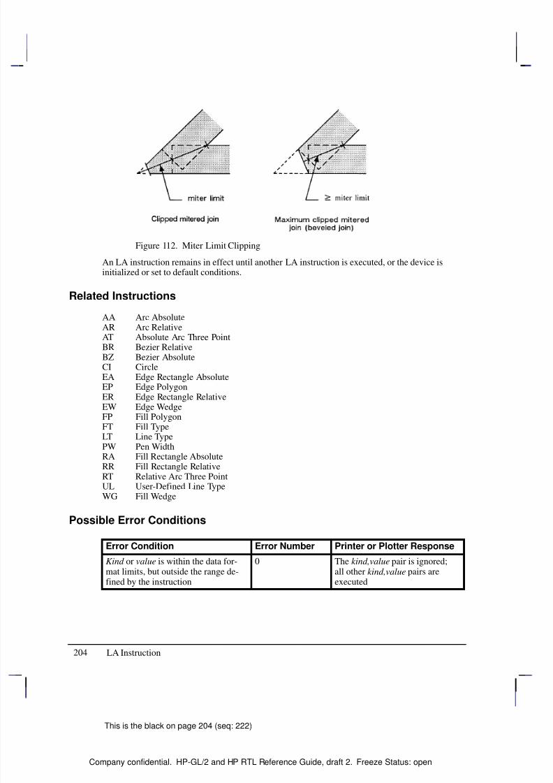
8/12/2019 HPGL2-RTL ReferenceGuide 5961-3526 540pages Sep96
http://slidepdf.com/reader/full/hpgl2-rtl-referenceguide-5961-3526-540pages-sep96 222/539
204
This is the black on page 204 (seq: 222)
Company confidential. HP-GL/2 and HP RTL Reference Guide, draft 2. Freeze Status: open
Figure 112. Miter Limit Clipping
An LA instruction remains in effect until another LA instruction is executed, or the device is
initialized or set to default conditions.
Related Instructions
AA Arc AbsoluteAR Arc RelativeAT Absolute Arc Three PointBR Bezier RelativeBZ Bezier AbsoluteCI CircleEA Edge Rectangle AbsoluteEP Edge PolygonER Edge Rectangle Relative
EW Edge WedgeFP Fill PolygonFT Fill TypeLT Line TypePW Pen WidthRA Fill Rectangle AbsoluteRR Fill Rectangle RelativeRT Relative Arc Three PointUL User-Defined Line TypeWG Fill Wedge
Possible Error Conditions
Error Condition Error Number Printer or Plotter ResponseKind or value is within the data for-mat limits, but outside the range de-fined by the instruction
0 The kind,value pair is ignored;all other kind,value pairs areexecuted
LA Instruction
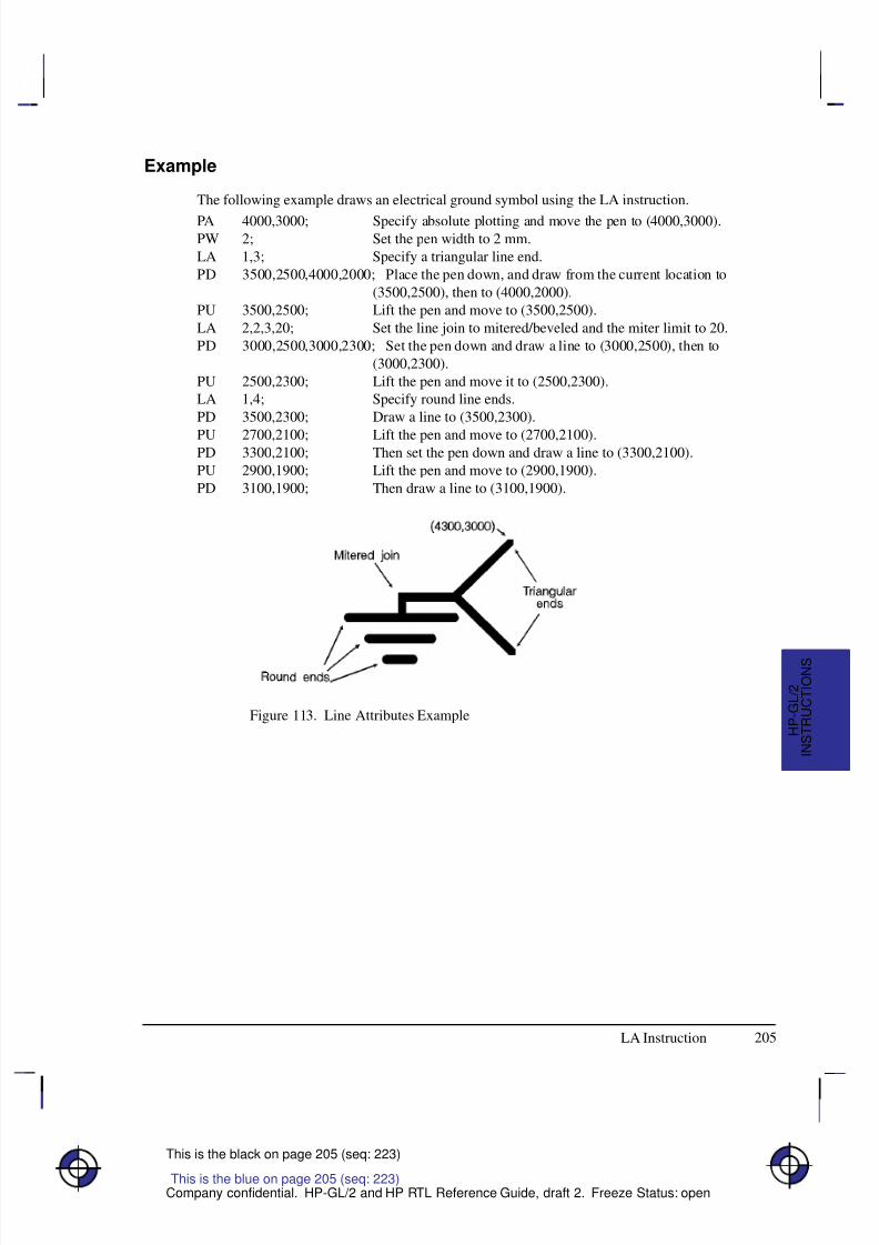
8/12/2019 HPGL2-RTL ReferenceGuide 5961-3526 540pages Sep96
http://slidepdf.com/reader/full/hpgl2-rtl-referenceguide-5961-3526-540pages-sep96 223/539
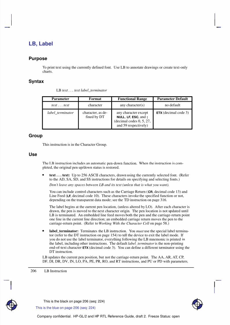
8/12/2019 HPGL2-RTL ReferenceGuide 5961-3526 540pages Sep96
http://slidepdf.com/reader/full/hpgl2-rtl-referenceguide-5961-3526-540pages-sep96 224/539
206
This is the black on page 206 (seq: 224)
Company confidential. HP-GL/2 and HP RTL Reference Guide, draft 2. Freeze Status: open
LB, Label
Purpose
To print text using the currently defined font. Use LB to annotate drawings or create text-onlycharts.
Syntax
LB text . . . text label_terminator
Á Á Á Á Á Á Á
Á Á Á Á Á Á Á
ParameterÁ Á Á Á Á Á
Á Á Á Á Á Á
FormatÁ Á Á Á Á Á Á Á
Á Á Á Á Á Á Á Á
Functional RangeÁ Á Á Á Á Á Á Á
Á Á Á Á Á Á Á Á
Parameter Default
Á Á Á Á Á Á Á
Á Á Á Á Á Á Á
text . . . text Á Á Á Á Á Á
Á Á Á Á Á Á
character Á Á Á Á Á Á Á Á
Á Á Á Á Á Á Á Á
any character(s) Á Á Á Á Á Á Á Á
Á Á Á Á Á Á Á Á
no default
Á Á Á Á Á Á Á
Á Á Á Á Á Á Á
Á Á Á Á Á Á Á
Á Á Á Á Á Á Á
Á Á Á Á Á Á Á
label_terminator
Á Á Á Á Á Á
Á Á Á Á Á Á
Á
Á Á Á Á Á
Á Á Á Á Á Á
Á Á Á Á Á Á
character, as de-fined by DT
Á Á Á Á Á Á Á Á
Á Á Á Á Á Á Á Á
Á
Á Á Á Á Á Á Á
Á Á Á Á Á Á Á Á
Á Á Á Á Á Á Á Á
any character except, , , and ;
(decimal codes 0, 5, 27,and 59 respectively)
Á Á Á Á Á Á Á Á
Á Á Á Á Á Á Á Á
Á
Á Á Á Á Á Á Á
Á Á Á Á Á Á Á Á
Á Á Á Á Á Á Á Á
(decimal code 3)
Group
This instruction is in the Character Group.
Use
The LB instruction includes an automatic pen-down function. When the instruction is com-pleted, the original pen up/down status is restored.
text . . . text: Up to 256 ASCII characters, drawn using the currently selected font. (Referto the AD, SA, SD, and SS instructions for details on specifying and selecting fonts.)
Don’t leave any spaces between LB and its text (unless that is what you want).
You can include control characters such as the Carriage Return (, decimal code 13) andLine Feed (, decimal code 10). These characters invoke the specified function or not,depending on the transparent data mode; see the TD instruction on page 316.
The label begins at the current pen location, (unless altered by LO). After each character isdrawn, the pen is moved to the next character origin. The pen location is not updated untilLB is terminated. An embedded line feed moves both the pen and the carriage-return pointone line in the current line direction; an embedded carriage return moves the pen to thecarriage-return point. (Refer to Working With the Character Cell on page 58.)
label_terminator: Terminates the LB instruction. You must use the special label termina-tor (refer to the DT instruction on page 154) to tell the device to exit the label mode. If you do not use the label terminator, everything following the LB mnemonic is printed inthe label, including other instructions. The default label_terminator is the non-printingend-of-text character (decimal code 3). You can define a different terminator using theDT instruction.
LB updates the current pen position, but not the carriage-return point. The AA, AR, AT, CP,DF, DI, DR, DV, IN, LO, PA, PE, PR, RO, and RT instructions, and PU or PD with parameters,
This is the blue on page 206 (seq: 224)
LB Instruction
8/12/2019 HPGL2-RTL ReferenceGuide 5961-3526 540pages Sep96
http://slidepdf.com/reader/full/hpgl2-rtl-referenceguide-5961-3526-540pages-sep96 225/539
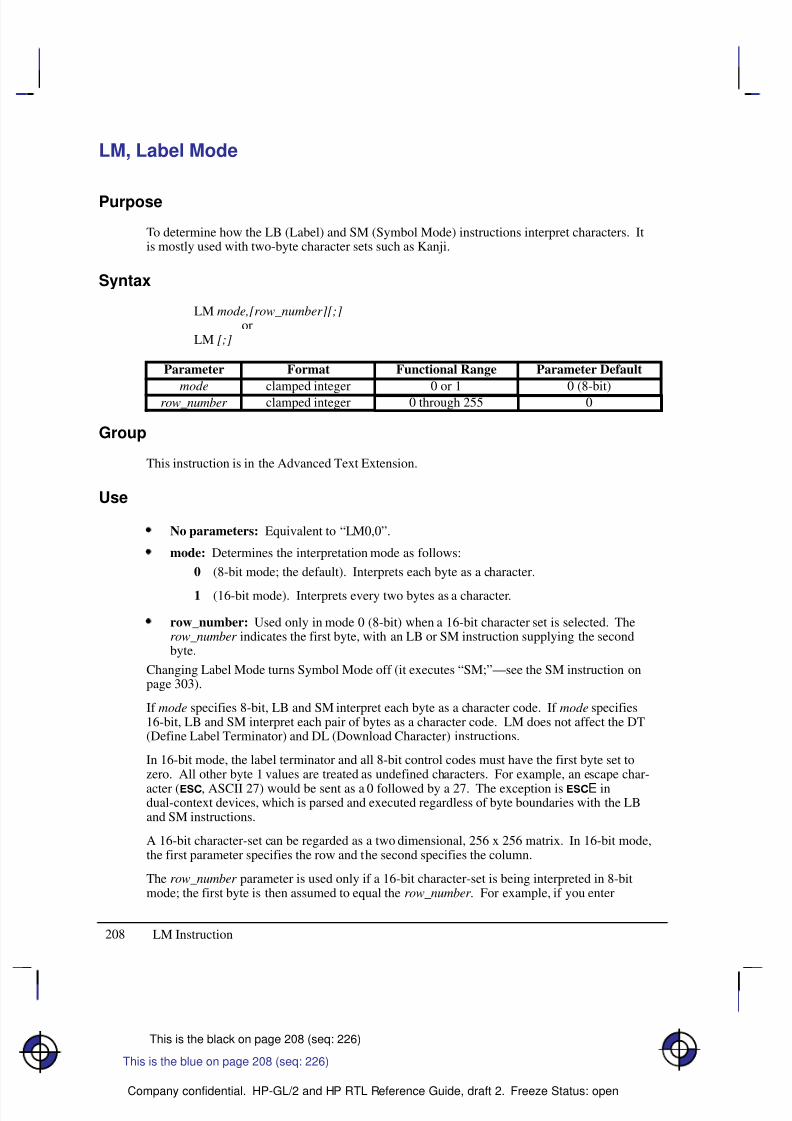
8/12/2019 HPGL2-RTL ReferenceGuide 5961-3526 540pages Sep96
http://slidepdf.com/reader/full/hpgl2-rtl-referenceguide-5961-3526-540pages-sep96 226/539
208
This is the black on page 208 (seq: 226)
Company confidential. HP-GL/2 and HP RTL Reference Guide, draft 2. Freeze Status: open
LM, Label Mode
Purpose
To determine how the LB (Label) and SM (Symbol Mode) instructions interpret characters. Itis mostly used with two-byte character sets such as Kanji.
Syntax
LM mode,[row_number][;]or
LM [;]
Á Á Á Á Á
Á Á Á Á Á
ParameterÁ Á Á Á Á Á Á Á
Á Á Á Á Á Á Á Á
FormatÁ Á Á Á Á Á Á Á
Á Á Á Á Á Á Á Á
Functional RangeÁ Á Á Á Á Á Á Á
Á Á Á Á Á Á Á Á
Parameter DefaultÁ Á Á Á Á
Á Á Á Á Á
mode
Á Á Á Á Á Á Á Á
Á Á Á Á Á Á Á Á
clamped integer
Á Á Á Á Á Á Á Á
Á Á Á Á Á Á Á Á
0 or 1
Á Á Á Á Á Á Á Á
Á Á Á Á Á Á Á Á
0 (8-bit)Á Á Á Á Á
Á Á Á Á Á
row_number Á Á Á Á Á Á Á Á
Á Á Á Á Á Á Á Á
clamped integer Á Á Á Á Á Á Á Á
Á Á Á Á Á Á Á Á
0 through 255 Á Á Á Á Á Á Á Á
Á Á Á Á Á Á Á Á
0
Group
This instruction is in the Advanced Text Extension.
Use
No parameters: Equivalent to “LM0,0”.
mode: Determines the interpretation mode as follows:
0 (8-bit mode; the default). Interprets each byte as a character.
1 (16-bit mode). Interprets every two bytes as a character.
row_number: Used only in mode 0 (8-bit) when a 16-bit character set is selected. Therow_number indicates the first byte, with an LB or SM instruction supplying the secondbyte.
Changing Label Mode turns Symbol Mode off (it executes “SM;”—see the SM instruction onpage 303).
If mode specifies 8-bit, LB and SM interpret each byte as a character code. If mode specifies16-bit, LB and SM interpret each pair of bytes as a character code. LM does not affect the DT(Define Label Terminator) and DL (Download Character) instructions.
In 16-bit mode, the label terminator and all 8-bit control codes must have the first byte set tozero. All other byte 1 values are treated as undefined characters. For example, an escape char-
acter (, ASCII 27) would be sent as a 0 followed by a 27. The exception is E indual-context devices, which is parsed and executed regardless of byte boundaries with the LBand SM instructions.
A 16-bit character-set can be regarded as a two dimensional, 256 x 256 matrix. In 16-bit mode,the first parameter specifies the row and the second specifies the column.
The row_number parameter is used only if a 16-bit character-set is being interpreted in 8-bitmode; the first byte is then assumed to equal the row_number . For example, if you enter
This is the blue on page 208 (seq: 226)
LM Instruction
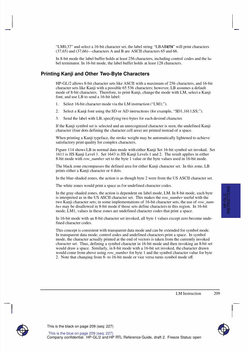
8/12/2019 HPGL2-RTL ReferenceGuide 5961-3526 540pages Sep96
http://slidepdf.com/reader/full/hpgl2-rtl-referenceguide-5961-3526-540pages-sep96 227/539
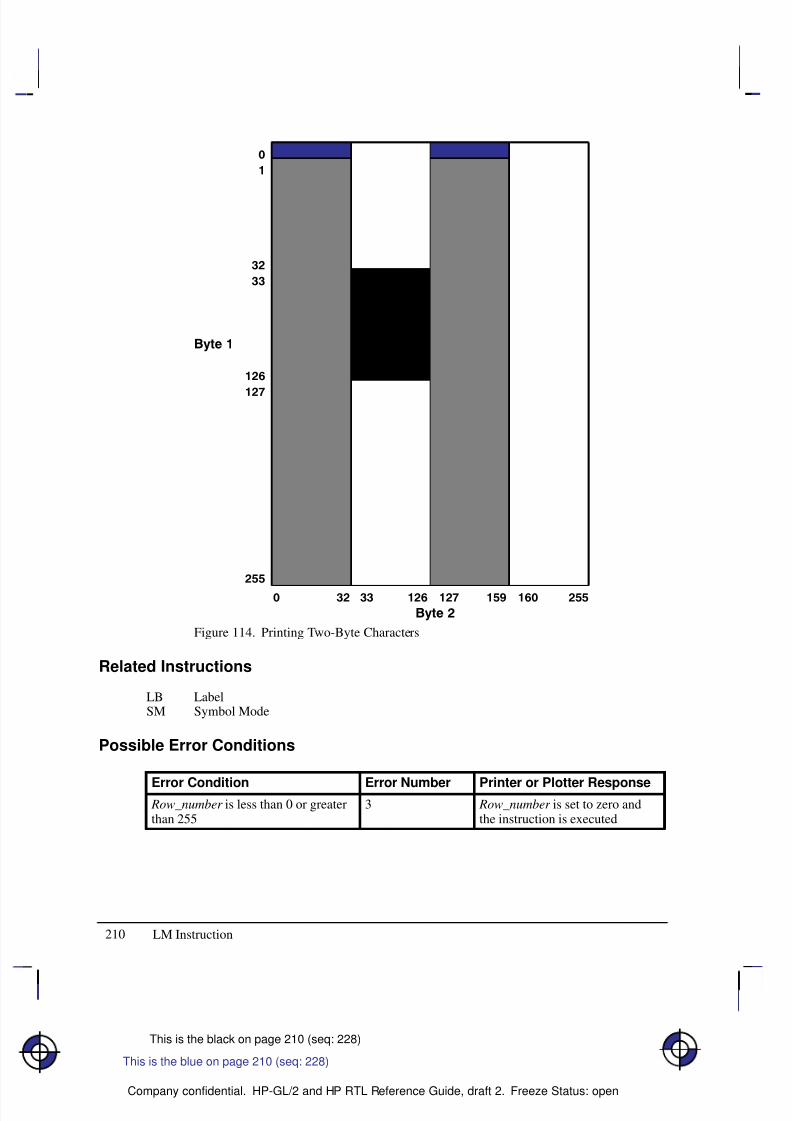
8/12/2019 HPGL2-RTL ReferenceGuide 5961-3526 540pages Sep96
http://slidepdf.com/reader/full/hpgl2-rtl-referenceguide-5961-3526-540pages-sep96 228/539
210
This is the black on page 210 (seq: 228)
Company confidential. HP-GL/2 and HP RTL Reference Guide, draft 2. Freeze Status: open
Figure 114. Printing Two-Byte Characters
Related Instructions
LB LabelSM Symbol Mode
Possible Error Conditions
Error Condition Error Number Printer or Plotter Response Row_number is less than 0 or greaterthan 255
3 Row_number is set to zero andthe instruction is executed
This is the blue on page 210 (seq: 228)
LM Instruction
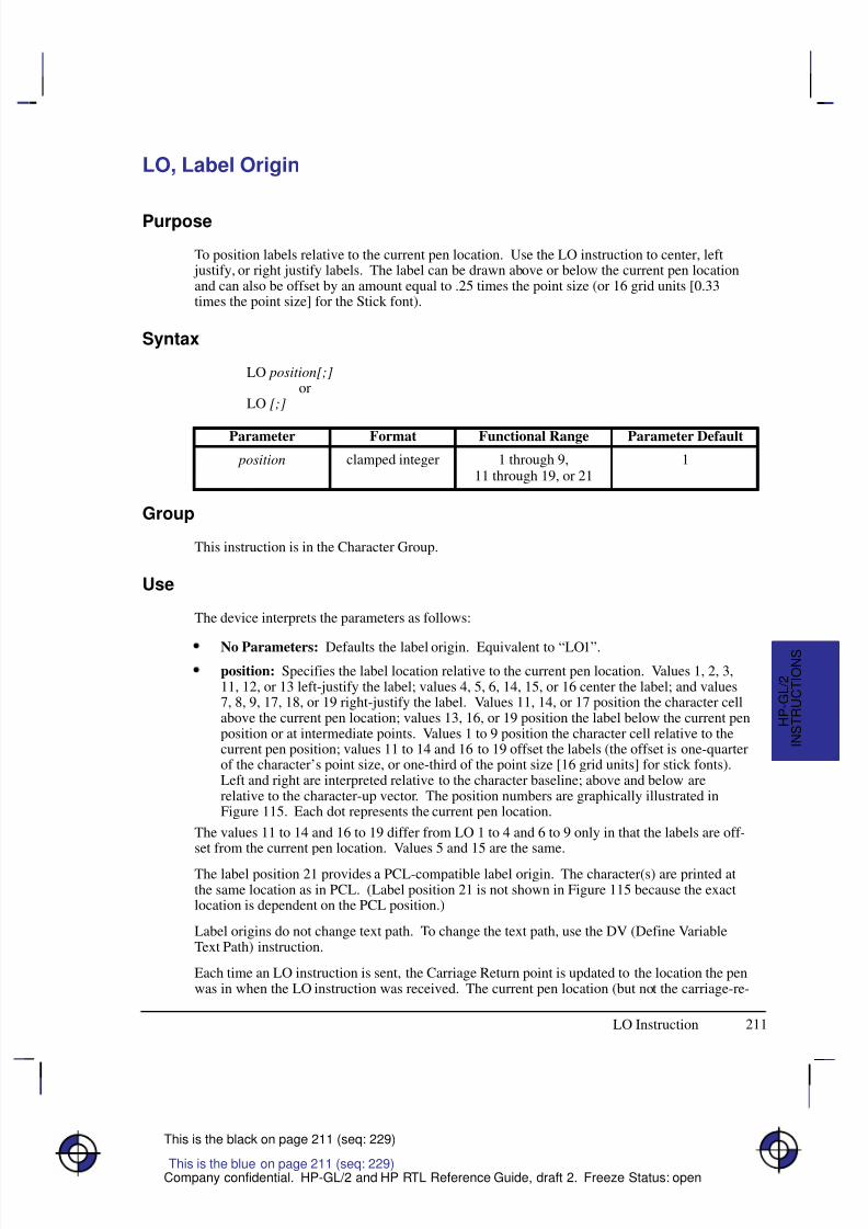
8/12/2019 HPGL2-RTL ReferenceGuide 5961-3526 540pages Sep96
http://slidepdf.com/reader/full/hpgl2-rtl-referenceguide-5961-3526-540pages-sep96 229/539
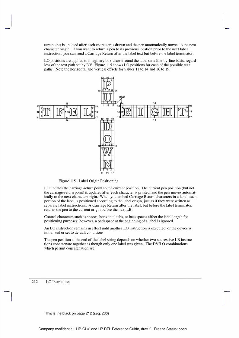
8/12/2019 HPGL2-RTL ReferenceGuide 5961-3526 540pages Sep96
http://slidepdf.com/reader/full/hpgl2-rtl-referenceguide-5961-3526-540pages-sep96 230/539
8/12/2019 HPGL2-RTL ReferenceGuide 5961-3526 540pages Sep96
http://slidepdf.com/reader/full/hpgl2-rtl-referenceguide-5961-3526-540pages-sep96 231/539
213
This is the black on page 213 (seq: 231)
Company confidential. HP-GL/2 and HP RTL Reference Guide, draft 2. Freeze Status: open
Text Path Label Origin
DV0 (right) LO’s 1, 2, 3, and 11, 12, 13, and 21
DV1 (down) LO’s 3, 6, 9, and 13, 16, 19
DV2 (left) LO’s 7, 8, 9, and 17, 18, 19
DV3 (up) LO’s 1, 4, 7, and 11, 14, 17, and 21
The DV and LO combination is applied on a line-by-line basis; a “line” is established by a car-riage return, line feed, or the label terminator.
The following two rules determine where the pen is positioned after a label string is drawn.Rule 1 is for DV/LO combinations which permit concatenation; rule 2 clarifies other DV/LOcombinations:
If a concatenation combination is specified, the pen position is updated to give the normaldelta X space between the last character of the first label, and the first character of the
second label.Note: For proportional fonts that use a pair-wise spacing table, the pen position is updatedusing an average delta X space.
If a non-concatenation combination is specified, the pen position that existed immediatelyprior to the LB instruction is restored.
Related Instructions
CP Character PlotDV Define Variable Text PathLB Label
Example
SP 1; Select pen number 1.
SC –4000,4000,–5000,5000; Specify scaling by assigning (–4000,–5000) to P1 and
(4000,5000) to P2.
SI .17,.26; Set the absolute character size to 0.17 cm wide by 0.26 cm high.
PA 0,500; Move to (0,500).
PD –500,0,0,–500,500,0,0,500; Set the pen down and draw lines from (0,500) to (–500,0),
to (0,–500), to (500,0), and then to (0,500).
DT#; Define label terminator as “#” character.
CI 10; Draw a small circle (radius 10 plotter-units) to represent the label
origin point.
LO 4; Specify a label origin of 4.
LBCentered on point#; Print “Centered on point”.
PU –500,0; Lift the pen and move to (–500,0).
CI 10; Draw another small circle.
LO 18; Specify a label origin of 18.
LBLeft center offset#; Print “Left center offset”.
PU 0,–500; Lift the pen.
CI 10; Draw another small circle.
This is the blue on page 213 (seq: 231)
LO Instruction
I N S T R U C T I O N S
H P - G L / 2
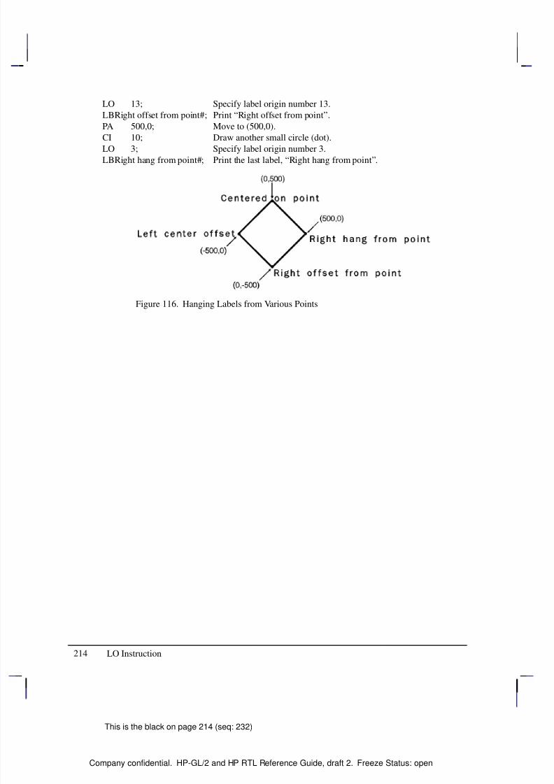
8/12/2019 HPGL2-RTL ReferenceGuide 5961-3526 540pages Sep96
http://slidepdf.com/reader/full/hpgl2-rtl-referenceguide-5961-3526-540pages-sep96 232/539
214
This is the black on page 214 (seq: 232)
Company confidential. HP-GL/2 and HP RTL Reference Guide, draft 2. Freeze Status: open
LO 13; Specify label origin number 13.
LBRight offset from point#; Print “Right offset from point”.
PA 500,0; Move to (500,0).
CI 10; Draw another small circle (dot).LO 3; Specify label origin number 3.
LBRight hang from point#; Print the last label, “Right hang from point”.
Figure 116. Hanging Labels from Various Points
LO Instruction
8/12/2019 HPGL2-RTL ReferenceGuide 5961-3526 540pages Sep96
http://slidepdf.com/reader/full/hpgl2-rtl-referenceguide-5961-3526-540pages-sep96 233/539
215
This is the black on page 215 (seq: 233)
Company confidential. HP-GL/2 and HP RTL Reference Guide, draft 2. Freeze Status: open
LT, Line Type
Purpose
To specify the line pattern to be used when drawing lines. Use LT to vary lines and enhanceyour plot. Note that the ends of dashed line segments in a line pattern are affected by currentline attributes (refer to the LA instruction on page 200).
Syntax
LT line_type[,pattern_length[,mode]][;]or
LT [;]or
LT 99 [;]
Á Á Á Á Á Á Á
Á Á Á Á Á Á Á
ParameterÁ Á Á Á Á Á Á
Á Á Á Á Á Á Á
FormatÁ Á Á Á Á Á Á
Á Á Á Á Á Á Á
Functional RangeÁ Á Á Á Á Á Á Á
Á Á Á Á Á Á Á Á
Parameter DefaultÁ Á Á Á Á Á Á
Á Á Á Á Á Á Á
Á Á Á Á Á Á Á
line_typeÁ Á Á Á Á Á Á
Á Á Á Á Á Á Á
Á Á Á Á Á Á Á
clamped integerÁ Á Á Á Á Á Á
Á Á Á Á Á Á Á
Á Á Á Á Á Á Á
–8 through 8,99
Á Á Á Á Á Á Á Á
Á Á Á Á Á Á Á Á
Á Á Á Á Á Á Á Á
solid linerestores previous line type
Á Á Á Á Á Á Á
Á Á Á Á Á Á Á
Á Á Á Á Á Á Á
pattern_lengthÁ Á Á Á Á Á Á
Á Á Á Á Á Á Á
Á Á Á Á Á Á Á
clamped realÁ Á Á Á Á Á Á
Á Á Á Á Á Á Á
Á Á Á Á Á Á Á
>0 through 32 767Á Á Á Á Á Á Á Á
Á Á Á Á Á Á Á Á
Á Á Á Á Á Á Á Á
4% of the distancebetween P1 and P2
Á Á Á Á Á Á Á
Á Á Á Á Á Á Á
modeÁ Á Á Á Á Á Á
Á Á Á Á Á Á Á
clamped integerÁ Á Á Á Á Á Á
Á Á Á Á Á Á Á
0 or 1Á Á Á Á Á Á Á Á
Á Á Á Á Á Á Á Á
0 (relative)
Group
This instruction is in the Line and Fill Attributes Group.
Use
The LT instruction applies to lines drawn by the AA, AR, AT, CI, EA, EP, ER, EW, FP, PA, PD,PE, PR, RA, RR, RT, and WG instructions. Line types are drawn using the current line attrib-utes set by the Line Attribute (LA) instruction. For example, if you have used LA to specifyrounded ends, the device draws each dash in a dashed line pattern with rounded ends.
No Parameters: Defaults the line type to solid and saves the previous line type, patternlength, and any unused portion of the pattern (residue).
line_type: Subsequent lines are drawn with the corresponding line pattern. Line patternscan be of fixed or adaptive type.
Positive line types (1 to 8) are fixed line types and use the specified pattern length todraw lines. Any unused part of the pattern (the residue) is carried over into the nextline to give the appearance of the pattern wrapping round corners. The residue issaved when any of the following instructions are received: CI, EA, EP, ER, EW, FP,PM, RA, RR, or WG. The residue is restored when the current pen position is restoredupon completion of these HP-GL/2 instructions. You can redefine the eight line typesusing the UL instruction.
The current residue and vector end point are also saved before each symbol is drawn,and on receipt of a CP, LB, or SM instruction. The current residue is restored if the
This is the blue on page 215 (seq: 233)
LT Instruction
I N S T R U C T I O N S
H P - G L / 2
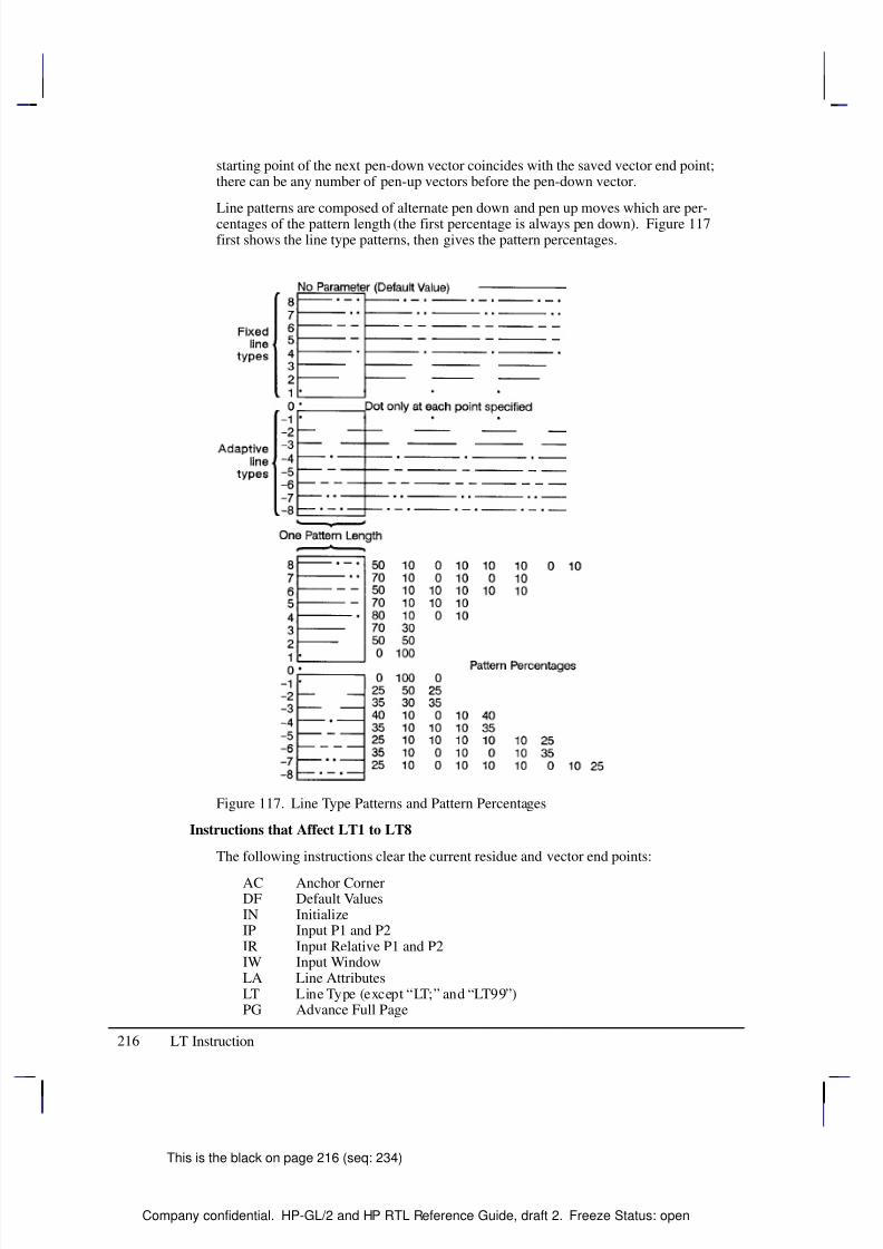
8/12/2019 HPGL2-RTL ReferenceGuide 5961-3526 540pages Sep96
http://slidepdf.com/reader/full/hpgl2-rtl-referenceguide-5961-3526-540pages-sep96 234/539
216
This is the black on page 216 (seq: 234)
Company confidential. HP-GL/2 and HP RTL Reference Guide, draft 2. Freeze Status: open
starting point of the next pen-down vector coincides with the saved vector end point;there can be any number of pen-up vectors before the pen-down vector.
Line patterns are composed of alternate pen down and pen up moves which are per-centages of the pattern length (the first percentage is always pen down). Figure 117first shows the line type patterns, then gives the pattern percentages.
Figure 117. Line Type Patterns and Pattern Percentages
Instructions that Affect LT1 to LT8
The following instructions clear the current residue and vector end points:
AC Anchor CornerDF Default ValuesIN InitializeIP Input P1 and P2IR Input Relative P1 and P2IW Input WindowLA Line AttributesLT Line Type (except “LT;” and “LT99”)PG Advance Full Page
LT Instruction
8/12/2019 HPGL2-RTL ReferenceGuide 5961-3526 540pages Sep96
http://slidepdf.com/reader/full/hpgl2-rtl-referenceguide-5961-3526-540pages-sep96 235/539
217
This is the black on page 217 (seq: 235)
Company confidential. HP-GL/2 and HP RTL Reference Guide, draft 2. Freeze Status: open
PW Pen WidthRF Raster Fill DefinitionRO Rotate Coordinate System
RP ReplotSC ScaleSP Select PenTR Transparency ModeUL User-Defined Line TypeWU Pen Width Unit Selection
A zero line type (0) draws only a dot at the X,Y coordinates for AA, AR, AT, BR, BZ,CI, PA, PD, PR, and RT instructions. Zero pen-down values and zero-length lines alsoproduce dots. A dot is a one plotter-unit long vector, drawn using the current line endand pen width. (Dots within lines are drawn at the correct angle, but zero-length vec-tors are drawn along the user’s current X-axis.)
Negative line types (–1 to –8) are adaptive line types, using the same patterns as linetypes 1 to 8. However the pattern length is automatically adjusted so that each line
contains one or more complete patterns.
Adaptive line types are derived from the corresponding fixed line types; if the fixedline type ends in a “pen-up stretch”, the first percentage is reduced by half and theamount that it is reduced is added as the last percentage. This ensures that the drawnvector end points are always visible when an adaptive line type is selected; the patternis “on” (or had the pen down) at the beginning and end of the pattern repeat segment.
For redefined fixed line types (see the UL instruction) that end in a “pen-downstretch”, the adaptive line type is derived by adding the first and last pen-down gappercentages and using half the sum for both the first and last gap percentages.
Note: Do not use an adaptive line type when you draw circles, arcs, wedges, or poly-gons. The device will attempt to draw the complete pattern in every chord; there are72 chords in a circle using the default chord angle.
LT99 restores the previous line type (and residue if it is a fixed-line type).
Note: If a solid line type is selected (“LT;”) when the LT99 instruction is issued, andthe current pen position has not changed, the previously selected line type can be in-voked using LT99. LT99 is ignored when a non-solid line type is in effect, or if thepen is in a different position from when the previous non-solid line ended. An exam-ple using this instruction is to print a line in a non-solid line type, followed by arectangle in solid black; beginning at the end point of the previous line, use LT99 toprint another line in the previous non-solid line type.
Instructions that Affect LT99
Sending any of the following instructions while plotting with a solid line type clearsthe previous line type and a subsequent “LT99” has no effect:
AC Anchor CornerBP Begin PlotDF Default ValuesIN InitializeIP Input P1 and P2IR Input Relative P1 and P2IW Input WindowLA Line AttributesLT Line Type (except “LT;” and “LT99”)
This is the blue on page 217 (seq: 235)
LT Instruction
I N S T R U C T I O N S
H P - G L / 2
8/12/2019 HPGL2-RTL ReferenceGuide 5961-3526 540pages Sep96
http://slidepdf.com/reader/full/hpgl2-rtl-referenceguide-5961-3526-540pages-sep96 236/539
218
This is the black on page 218 (seq: 236)
Company confidential. HP-GL/2 and HP RTL Reference Guide, draft 2. Freeze Status: open
PG Advance Full PagePW Pen WidthRF Raster Fill Definition
RO Rotate Coordinate SystemSC ScaleSP Select PenTR Transparency ModeUL User-Defined Line TypeWU Pen Width Unit Selection
pattern_length: Specifies the length of one complete line pattern, either as a percentageof the diagonal distance between the scaling points P1 and P2 or in millimeters (see modebelow). You must specify a length greater than zero (or use the default). If you do notspecify a length, the device uses the last value specified.
mode: Specifies how the values of the pattern_length parameter are interpreted. If youdo not specify a mode, the device uses the last value specified.
0 Relative mode: Interprets the pattern_length parameter as a percentage of thediagonal distance between P1 and P2.
When specified as a percentage, the pattern length changes along with changes inP1 and P2.
1 Absolute mode: Interprets the pattern_length parameter in millimeters.
When specified in millimeters, fixed line-type patterns assume the specifiedlength, but adaptive line-type pattern lengths are adjusted downward to fit an inte-gral number of patterns per vector. (This is true for relative mode and absolutemode.)
If you do not specify the pattern_length and mode parameters, then the device uses their currentvalues. When using relative mode and isotropic scaling, the pattern_length changes withchanges to X
min,Y
min and X
max,Y
max.
An LT instruction remains in effect until another LT instruction is executed or the device is ini-tialized or set to default conditions.
Related Instructions
AA Arc AbsoluteAR Arc RelativeAT Absolute Arc Three PointCI CircleEA Edge Rectangle AbsoluteEP Edge PolygonER Edge Rectangle Relative
EW Edge WedgeFP Fill PolygonFT Fill TypePA Plot AbsolutePD Pen DownPE Polyline EncodedPR Plot RelativePW Pen WidthRA Fill Rectangle AbsoluteRR Fill Rectangle Relative
LT Instruction
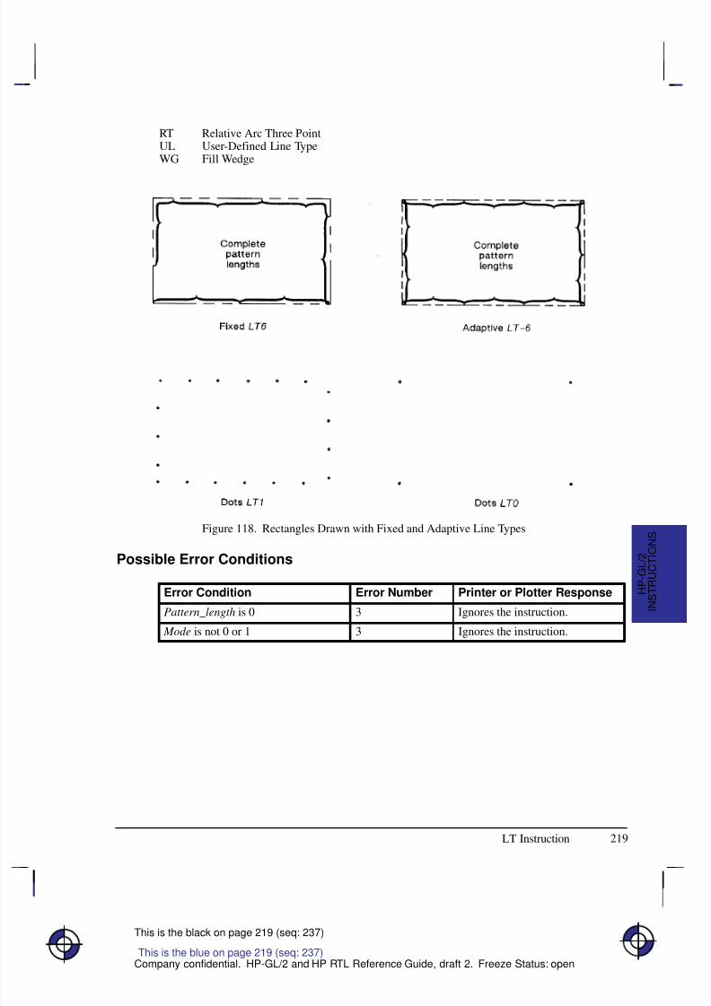
8/12/2019 HPGL2-RTL ReferenceGuide 5961-3526 540pages Sep96
http://slidepdf.com/reader/full/hpgl2-rtl-referenceguide-5961-3526-540pages-sep96 237/539
219
This is the black on page 219 (seq: 237)
Company confidential. HP-GL/2 and HP RTL Reference Guide, draft 2. Freeze Status: open
RT Relative Arc Three PointUL User-Defined Line TypeWG Fill Wedge
Figure 118. Rectangles Drawn with Fixed and Adaptive Line Types
Possible Error Conditions
Error Condition Error Number Printer or Plotter Response
Pattern_length is 0 3 Ignores the instruction.
Mode is not 0 or 1 3 Ignores the instruction.
This is the blue on page 219 (seq: 237)
LT Instruction
I N S T R U C T I O N S
H P - G L / 2
8/12/2019 HPGL2-RTL ReferenceGuide 5961-3526 540pages Sep96
http://slidepdf.com/reader/full/hpgl2-rtl-referenceguide-5961-3526-540pages-sep96 238/539
220
This is the black on page 220 (seq: 238)
Company confidential. HP-GL/2 and HP RTL Reference Guide, draft 2. Freeze Status: open
MC, Merge Control
Purpose
To provide control over the color of those pixels where two or more graphics intersect on thepage. This instruction is for raster devices only; it performs no function on pen plotters.
Syntax
MC mode[,opcode][;]or
MC [;]
Á Á Á Á Á Á Á
Á Á Á Á Á Á Á
ParameterÁ Á Á Á Á Á
Á Á Á Á Á Á
FormatÁ Á Á Á Á Á Á Á
Á Á Á Á Á Á Á Á
Functional RangeÁ Á Á Á Á Á Á Á
Á Á Á Á Á Á Á Á
Parameter DefaultÁ Á Á Á Á Á Á
Á Á Á Á Á Á Á
mode
Á Á Á Á Á Á
Á Á Á Á Á Á
clamped integer
Á Á Á Á Á Á Á Á
Á Á Á Á Á Á Á Á
0 or 1
Á Á Á Á Á Á Á Á
Á Á Á Á Á Á Á Á
0 (off)Á Á Á Á Á Á Á
Á Á Á Á Á Á Á
Á Á Á Á Á Á Á
opcodeÁ Á Á Á Á Á
Á
Á Á Á Á Á
Á Á Á Á Á Á
clamped integerÁ Á Á Á Á Á Á Á
Á
Á Á Á Á Á Á Á
Á Á Á Á Á Á Á Á
0 to 255Á Á Á Á Á Á Á Á
Á
Á Á Á Á Á Á Á
Á Á Á Á Á Á Á Á
252 (mode=0)168 (mode=1)
Group
This instruction is in the Technical Graphics and the Advanced Drawing Extensions.
Use
The merged color is a result of a device-dependent table look-up algorithm in the device. Thetable look-up functions on a pixel-by-pixel basis and applied to all graphics done with HP-GL/2
instructions: vectors, text, and polygon fill (including raster patterns).
No parameters: equivalent to “MC0”. Defaults merge control to off.
mode: A clamped integer which specifies one of the following modes:
0 Merge control off : each graphic replaces the pixels at the destination location, andoverwrites the pixels without merging. This is the default.
1 Merge control on: the device creates a merge color at the intersection of the vectors.
opcode: Specifies the logical operations that are to be performed on a source, destination,and patterned image before drawing the final image. These raster operations are defined inRGB space and are listed in the table on pages 475 and 476. This parameter is a clampedinteger in the range 0 to 255. The default is 252 when mode=0, and 168 when mode=1.
The logical operations are defined in reverse polish notation (RPN) with the following defini-tions:
D: Destination (that is, the pixel that is already defined at the point)
S: Source (the new pixel to be applied to the point)
T: Texture (any fill pattern)
a: And o: Or
n: Not x: Exclusive or
This is the blue on page 220 (seq: 238)
MC Instruction
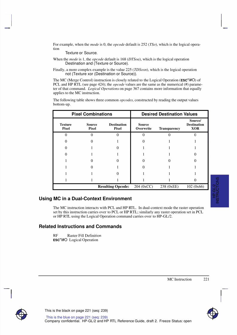
8/12/2019 HPGL2-RTL ReferenceGuide 5961-3526 540pages Sep96
http://slidepdf.com/reader/full/hpgl2-rtl-referenceguide-5961-3526-540pages-sep96 239/539
8/12/2019 HPGL2-RTL ReferenceGuide 5961-3526 540pages Sep96
http://slidepdf.com/reader/full/hpgl2-rtl-referenceguide-5961-3526-540pages-sep96 240/539
222
This is the black on page 222 (seq: 240)
Company confidential. HP-GL/2 and HP RTL Reference Guide, draft 2. Freeze Status: open
MG, Message
Purpose
To write a message to the display on a device’s control panel. If the device does not have acontrol panel with a display, this instruction is ignored (a NOP).
Syntax
MG message[;]or
MG [;]
Á Á Á Á Á Á Á
Á Á Á Á Á Á Á
ParameterÁ Á Á Á Á Á
Á Á Á Á Á Á
FormatÁ Á Á Á Á Á Á Á
Á Á Á Á Á Á Á Á
Functional RangeÁ Á Á Á Á Á Á Á
Á Á Á Á Á Á Á Á
Parameter DefaultÁ Á Á Á Á Á Á
Á Á Á Á Á Á Á
message
Á Á Á Á Á Á
Á Á Á Á Á Á
quoted string
Á Á Á Á Á Á Á Á
Á Á Á Á Á Á Á Á
any characters
Á Á Á Á Á Á Á Á
Á Á Á Á Á Á Á Á
no default
Group
This instruction is in the Technical Graphics Extension.
Use
Character codes in the message are interpreted in the character set enabled at power-up for dis-play of control-panel menu commands and error messages. The character set selected forlabeling does not affect the display of this instruction.
No parameters: clears the display.
message: Long text lines automatically wrap to the next line if one exists. Once the endof the display is reached, however, the message does not wrap and overwrite the beginningof the display.
You can use the following control codes within your message; all other control codes (seepage 67) are ignored: Backspace (), Line Feed (), Carriage Return ().
If your device uses one display for displaying messages and control-panel menus, the deviceswitches between the MG message and the control-panel menu (for user responses). The de-vice restores the MG message after the user responds to the control-panel prompt. The deviceretains the message until it is overwritten or cleared by another MG instruction or the device isinitialized.
This is the blue on page 222 (seq: 240)
MG Instruction
8/12/2019 HPGL2-RTL ReferenceGuide 5961-3526 540pages Sep96
http://slidepdf.com/reader/full/hpgl2-rtl-referenceguide-5961-3526-540pages-sep96 241/539
223
This is the black on page 223 (seq: 241)
Company confidential. HP-GL/2 and HP RTL Reference Guide, draft 2. Freeze Status: open
MT, Media Type
Purpose
To indicate the type of media loaded in the device. This instruction, when used, must appear inthe picture header state; otherwise it is ignored.
Syntax
MT type[;]or
MT [;]
Á Á Á Á Á Á Á
Á Á Á Á Á Á Á
ParameterÁ Á Á Á Á Á Á
Á Á Á Á Á Á Á
FormatÁ Á Á Á Á Á Á Á
Á Á Á Á Á Á Á Á
Functional RangeÁ Á Á Á Á Á Á
Á Á Á Á Á Á Á
Parameter DefaultÁ Á Á Á Á Á Á
Á Á Á Á Á Á Á
type
Á Á Á Á Á Á Á
Á Á Á Á Á Á Á
clamped integer
Á Á Á Á Á Á Á Á
Á Á Á Á Á Á Á Á
0 to 6
Á Á Á Á Á Á Á
Á Á Á Á Á Á Á
device-dependent
Group
This instruction is in the Technical Graphics Extension.
Use
Your device uses this information according to its plotting or printing technology. The devicemight, for example, change the resolution, the ink-drop volume, the speed of plotting or print-ing, or change from unidirectional to bidirectional plotting, or respond in some other way asnecessary. The actual changes made may take into account both the MT and QL (Quality Lev-el) instructions, internal knowledge of the pen type, and any control-panel set-ups.
All devices recognize the types listed, though several of the types may be treated in the sameway, for example, 1 and 3.
No parameters: The device uses the front-panel setting.
type: A clamped integer in the range 0 to 6, specifying the type of media, as follows:
0 Paper
1 Transparency film
2 Vellum
3 Polyester film, such as Mylar
4 Translucent paper
5 Special paper
6 Glossy paper
Related Instruction
QL Quality Level
This is the blue on page 223 (seq: 241)
MT Instruction
I N S T R U C T I O N S
H P - G L / 2

8/12/2019 HPGL2-RTL ReferenceGuide 5961-3526 540pages Sep96
http://slidepdf.com/reader/full/hpgl2-rtl-referenceguide-5961-3526-540pages-sep96 242/539
224
This is the black on page 224 (seq: 242)
Company confidential. HP-GL/2 and HP RTL Reference Guide, draft 2. Freeze Status: open
Possible Error Conditions
Error Condition Error Number Printer or Plotter Response
Instruction used outside picture head-er state (see page 78)
1 Ignores instruction
MT Instruction
8/12/2019 HPGL2-RTL ReferenceGuide 5961-3526 540pages Sep96
http://slidepdf.com/reader/full/hpgl2-rtl-referenceguide-5961-3526-540pages-sep96 243/539
225
This is the black on page 225 (seq: 243)
Company confidential. HP-GL/2 and HP RTL Reference Guide, draft 2. Freeze Status: open
NP, Number of Pens
Purpose
To establish the size (the number of pens) of the HP-GL/2 palette.
Syntax
NP n[;]or
NP [;]
Á Á Á Á Á Á Á
ParameterÁ Á Á Á Á Á Á
FormatÁ Á Á Á Á Á Á Á
Functional RangeÁ Á Á Á Á Á Á
Parameter DefaultÁ Á Á Á Á Á Á
Á
Á Á Á Á Á Á
Á Á Á Á Á Á Á
n
Á Á Á Á Á Á Á
Á
Á Á Á Á Á Á
Á Á Á Á Á Á Á
clamped integerÁ Á Á Á Á Á Á Á
Á
Á Á Á Á Á Á Á
Á Á Á Á Á Á Á Á
device-dependent *Á Á Á Á Á Á Á
Á
Á Á Á Á Á Á
Á Á Á Á Á Á Á
device-dependent **
* Parameter must be a power of two.
** The default palette size for monochrome raster devices is 2. The default palette sizefor color raster devices is 8.
Group
This instruction is in the Palette Extension.
Use
The palette is an array of logical pens, each having an associated color value and an associated
width. Define pen colors through the PC (Pen Color Assignment) instruction, described onpage 239. Establish pen widths through the PW (Pen Width) and WU (Pen Width Units Selec-tion) instructions, described on pages 264 and 328 respectively.
No Parameters: Defaults the palette size for monochrome devices to 2 pens, and forcolor raster devices to 8 pens.
n: Sets the size of the palette as a power of 2. If n is not a power of 2, the device usesthe next larger power of 2. The maximum value of n, while device-dependent, is equal toor greater than the number of distinct colors the device can produce. If n is greater than themaximum, the device uses the maximum-size palette.
For pen plotters, NP defines the number of pens and also pen number 0; thus “NP8” definespens 1 through 8 plus no pen (pen 0).
For raster devices, NP defines the palette size, for pens numbered 0 through n–1; thus
“NP8” defines pens 0 through 7.
NP does not default pen colors or widths for existing pen values. For example, if the palettesize is decreased from 8 to 4, the pen colors and widths of the first four pens of the old paletteare retained. If the palette size is increased from 8 to 16, the colors and widths for the firsteight pens remain the same, and those for the remainder are defaulted.
If the current pen is outside the range of the new palette size, the device applies a modulo func-tion to select a pen number within the range of the new palette. The base of the modulo
This is the blue on page 225 (seq: 243)
NP Instruction
I N S T R U C T I O N S
H P - G L / 2
8/12/2019 HPGL2-RTL ReferenceGuide 5961-3526 540pages Sep96
http://slidepdf.com/reader/full/hpgl2-rtl-referenceguide-5961-3526-540pages-sep96 244/539
226
This is the black on page 226 (seq: 244)
Company confidential. HP-GL/2 and HP RTL Reference Guide, draft 2. Freeze Status: open
function is either n (for a pen plotter) or n–1 (for a raster device), that is 8 or 7 in the examplesabove. See the SP instruction on page 306.
This instruction is usually defaulted by the IN (Initialize) and BP (Begin Plot) instructions.
In dual context environments, you should import the palettes created within PCL, rather thandefining palettes with this instruction.
Possible Error Conditions
Error Condition Error Number Printer or Plotter Response
n<2 3 Ignores instruction
NP Instruction
8/12/2019 HPGL2-RTL ReferenceGuide 5961-3526 540pages Sep96
http://slidepdf.com/reader/full/hpgl2-rtl-referenceguide-5961-3526-540pages-sep96 245/539
227
This is the black on page 227 (seq: 245)
Company confidential. HP-GL/2 and HP RTL Reference Guide, draft 2. Freeze Status: open
NR, Not Ready
Purpose
To take the device off-line for a specified amount of time. This can enable you to set control-panel conditions before starting to plot or print.
Syntax
NR timeout[;]or
NR [;]
Á Á Á Á Á Á Á
Á Á Á Á Á Á Á
ParameterÁ Á Á Á Á Á Á
Á Á Á Á Á Á Á
FormatÁ Á Á Á Á Á Á Á
Á Á Á Á Á Á Á Á
Functional RangeÁ Á Á Á Á Á Á
Á Á Á Á Á Á Á
Parameter DefaultÁ Á Á Á Á Á Á
Á Á Á Á Á Á Á
timeout
Á Á Á Á Á Á Á
Á Á Á Á Á Á Á
clamped integer
Á Á Á Á Á Á Á Á
Á Á Á Á Á Á Á Á
0 to 7200
Á Á Á Á Á Á Á
Á Á Á Á Á Á Á
0
Group
This instruction is in the Technical Graphics Extension.
Use
Place this instruction at the beginning of a plot after the IN or BP instruction. The timeout fea-ture of this instruction allows the user to set up pen groupings, media registration, pen force andacceleration, and so on. The device restores its online status and resumes plotting when eitherthe timeout elapses or the user puts the device back online (whichever comes first).
No parameters: Defaults the timeout to zero (no time-out); equivalent to “NR0”.
timeout: Specifies in seconds how long a user may need to perform any control-panelset-up operations or media loading. The maximum time-out is device-dependent and maybe clamped without error.
On devices that cannot perform a page advance, the PG instruction places the device in a “notready” state. The device remains off-line until new media is loaded or the necessary user inter-action occurs.
The function performed by “NR;” may produce an indefinite time-out by enabling single-usermode in a device that can be logically configured to be either a shared or a single-user device,for example, a device that can accept plots from several ports at once, by interleaving plots in aqueue, or from a single port with no interleaving. This change is device-dependent and is en-abled using front-panel interaction or switches that can be set by the user.
This is the blue on page 227 (seq: 245)
NR Instruction
I N S T R U C T I O N S
H P - G L / 2
8/12/2019 HPGL2-RTL ReferenceGuide 5961-3526 540pages Sep96
http://slidepdf.com/reader/full/hpgl2-rtl-referenceguide-5961-3526-540pages-sep96 246/539
228
This is the black on page 228 (seq: 246)
Company confidential. HP-GL/2 and HP RTL Reference Guide, draft 2. Freeze Status: open
OD, Output Digitized Point and Pen Status
Purpose
To output the X,Y coordinates and pen status (up or down) associated with the last digitizedpoint. The ranges of the X,Y coordinates are the hard-clip limits of the device; the pen status iseither 0 (up) or 1 (down).
Syntax
OD ;
You must use a terminator with output instructions.
Group
This instruction is in the Digitizing Extension.
Use
Use the following procedure for sending output instructions:
1. Send the OD instruction to the device as you do other HP-GL/2 instructions.
2. Read the device’s output response immediately using an input statement appropriate toyour programming language, keeping in mind the number and type of the variables.
Á Á Á Á Á Á Á Á
Á Á Á Á Á Á Á Á
ResponseÁ Á Á Á Á Á
Á Á Á Á Á Á
FormatÁ Á Á Á Á Á Á Á
Á Á Á Á Á Á Á Á
RangeÁ Á Á Á Á Á Á Á
Á
Á Á Á Á Á Á Á
Á Á Á Á Á Á Á Á
x,y,pen status (followed
by a terminator)
Á Á Á Á Á Á
Á
Á Á Á Á Á
Á Á Á Á Á Á
x,y: current unitsÁ Á Á Á Á Á Á Á
Á
Á Á Á Á Á Á Á
Á Á Á Á Á Á Á Á
device-dependent
(at least –223 to 223–1)Á Á Á Á Á Á Á Á
Á Á Á Á Á Á Á Á
Á Á Á Á Á Á
Á Á Á Á Á Á
pen status: integerÁ Á Á Á Á Á Á Á
Á Á Á Á Á Á Á Á
0 (up) or 1 (down)
Receipt of this instruction clears bit position 2 of the OS instruction status byte. The tim-ing of output depends on the interface you are using.
The terminator is a carriage return () for RS-232-C, Bi-Tronics, and MIO interfaces andcarriage return and line feed ( ) for HP-IB interfaces.
3. Output digitized points one at a time. Digitize the point, then output the point to the com-puter. Continue in this manner until all points on your plot are digitized.
Related Instructions
DC Digitize ClearDP Digitize PointOS Output Status
Possible Error Conditions
Error Condition Error Number Printer or Plotter Response
One or more parameters are specified 2 The parameters are ignored
This is the blue on page 228 (seq: 246)
OD Instruction
8/12/2019 HPGL2-RTL ReferenceGuide 5961-3526 540pages Sep96
http://slidepdf.com/reader/full/hpgl2-rtl-referenceguide-5961-3526-540pages-sep96 247/539
229
This is the black on page 229 (seq: 247)
Company confidential. HP-GL/2 and HP RTL Reference Guide, draft 2. Freeze Status: open
OE, Output Error
Purpose
To debug programs by retrieving a number that corresponds to the HP-GL/2 error received bythe plotter since the most recent OE, BP, or IN instruction, or power-up. Do not use thisinstruction on networks or unidirectional interfaces.
Syntax
OE ;
You must use a terminator with output instructions.
Group
This instruction is in the Technical Graphics Extension.
Use
The OE instruction outputs an integer in the range 0 through 7, corresponding to the first HP-GL/2 error (if any) that has occurred. The plotter only outputs the first error. If you suspectmore than one error, place the instruction in as many locations in your program as necessary.The following table defines the error numbers:
HP-GL/2Error Number Meaning
0 No error
1 Unrecognized instruction (or not recognized in current state)
2 Wrong number of parameters
3 Out-of-range or invalid parameter
4 and 5 Not used
6 Position overflow (“lost” mode; see page 23)
7 Buffer overflow, or out of memory
After returning the error number, the plotter sets its internal error number to zero, and clearsbit 5 of the status byte (see the OS instruction), indicating that no error has occurred since thelast OE instruction.
A posted error is not changed until it is cleared.
Multiple errors are set from left to right. For example, “LA 1,9,2;” causes an invalid parametererror (3) because of the “9”, not a wrong number of parameters error (2).
An instruction is ignored for the following error conditions:
Unrecognized instructionMissing required parametersParameter exceeds the defined limits.
This is the blue on page 229 (seq: 247)
OE Instruction
I N S T R U C T I O N S
H P - G L / 2
8/12/2019 HPGL2-RTL ReferenceGuide 5961-3526 540pages Sep96
http://slidepdf.com/reader/full/hpgl2-rtl-referenceguide-5961-3526-540pages-sep96 248/539
230
This is the black on page 230 (seq: 248)
Company confidential. HP-GL/2 and HP RTL Reference Guide, draft 2. Freeze Status: open
If more parameters are supplied than are expected for an instruction, the extra parameters areignored and the instruction is executed normally. An error 2 is posted.
If the polygon buffer is full and insertion of more data is attempted, only the portion of thepolygon that fits in the buffer is edged and filled; then an error 7 is posted. The polygon bufferis large enough to store at least 512 vertices.
If a parameter in the AD, LA, PA, PD, PR, PU, or SD instructions exceeds the limits defined bythe data format type, the out-of-range parameter and all subsequent parameters are ignored.However, if a kind or value parameter to the AD, BP, LA, or SD instruction is within the dataformat type limits, but outside the range defined by the instruction, that parameter pair is ig-nored; all preceding and subsequent valid pairs are executed. Integer parameter values arerounded before range checking is performed.
Example
This sequence of instructions contains two errors:
PA 1000,1000,20; PA instruction should have an even number of parametersED ; Non-existent instruction
OE ; Output Error
This OE instruction returns 2 followed by a terminator. (The terminator is a carriage return[] for RS-232-C, Bi-Tronics, and MIO interfaces and carriage return and line feed [ ] forHP-IB interfaces.) By referring to the table, you know that error 2 indicates the wrong numberof parameters. Once the first error is corrected, run the program again to find the other HP-GL/2 error.
OE Instruction
8/12/2019 HPGL2-RTL ReferenceGuide 5961-3526 540pages Sep96
http://slidepdf.com/reader/full/hpgl2-rtl-referenceguide-5961-3526-540pages-sep96 249/539
231
This is the black on page 231 (seq: 249)
Company confidential. HP-GL/2 and HP RTL Reference Guide, draft 2. Freeze Status: open
OH, Output Hard-Clip Limits
Purpose
To output the X,Y coordinates of the current hard-clip limits to the computer. Use OH to deter-mine the plotter-unit dimensions of the area within which plotting can occur. Do not use thisinstruction on networks or on unidirectional interfaces.
Syntax
OH ;
You must use a terminator with output instructions.
Group
This instruction is in the Technical Graphics Extension.
Use
The OH instruction outputs four integer values, XLL, YLL, XUR, YUR, representing the hard-cliplimits.
The coordinates are always expressed in plotter-units and represent the lower-left (XLL, YLL)and upper-right (XUR, YUR) corners of the hard-clip limits. After sending the OH instruction,have your computer program immediately read the device’s output response.
Example
The following program outputs the plotter identification. Use whatever statements your com-puter language requires to perform the input and output operations.
Send to the device: “%–1BBPIN” Enter HP-GL/2 mode, begin a plot, and ini-
tialize HP-GL/2.
Send to the device: “OH;” Output Hard-Clip Limits.
Read from the device: A,B,Y,Z Read the values into four variables, A, B, Y, and Z.
Print: A,B,Y,Z Print out the four variables, A, B, Y, and Z.
Typical output from the OH instruction might be:
0 0 21050 15000
followed by a terminator. (The terminator is a carriage return [] for RS-232-C, Bi-Tronics,
and MIO interfaces and carriage return and line feed [ ] for HP-IB interfaces.)
Related Instruction
PS Plot Size
This is the blue on page 231 (seq: 249)
OH Instruction
I N S T R U C T I O N S
H P - G L / 2
8/12/2019 HPGL2-RTL ReferenceGuide 5961-3526 540pages Sep96
http://slidepdf.com/reader/full/hpgl2-rtl-referenceguide-5961-3526-540pages-sep96 250/539
232
This is the black on page 232 (seq: 250)
Company confidential. HP-GL/2 and HP RTL Reference Guide, draft 2. Freeze Status: open
OI, Output Identification
Purpose
To output the plotter’s identifying order number. This information is useful in a remote operat-ing configuration (where several plotters are connected to the computer) to determine whichplotter model is online, or when software needs the plotter’s model number. Do not use thisinstruction on networks or on unidirectional interfaces.
Syntax
OI ;
You must use a terminator with output instructions.
Group
This instruction is in the Technical Graphics Extension.
Use
The OI instruction outputs the plotter ID, which is a character string of up to 30 characters, andrepresents the device’s order number and letter.
Example
The following program outputs the plotter identification. Use whatever statements your com-
puter language requires to perform the input and output operations.Send to the device: “%–1BBPIN” Enter HP-GL/2 mode, begin a plot, and ini-
tialize HP-GL/2.
Send to the device: “OI;” Output Identification.
Read from the device: A$ Read the device’s identification into the program.
Print: A$ Print it out.
Typical output from this instruction might be:
C4699A
followed by a terminator. (The terminator is a carriage return [] for RS-232-C, Bi-Tronics,and MIO interfaces and carriage return and line feed [ ] for HP-IB interfaces.)
This is the blue on page 232 (seq: 250)
OI Instruction
8/12/2019 HPGL2-RTL ReferenceGuide 5961-3526 540pages Sep96
http://slidepdf.com/reader/full/hpgl2-rtl-referenceguide-5961-3526-540pages-sep96 251/539
233
This is the black on page 233 (seq: 251)
Company confidential. HP-GL/2 and HP RTL Reference Guide, draft 2. Freeze Status: open
OP, Output P1 and P2
Purpose
To output the X, Y coordinates (in plotter-units) of the current scaling points P1 and P2 to thecomputer. Use OP to help compute the number of plotter-units per user-unit when scaling is on.OP can also be used with the IW (Input Window) instruction to set the window to P1 and P2from your program. Do not use this instruction on networks or on unidirectional interfaces.
Syntax
OP ;
You must use a terminator with output instructions.
Group
This instruction is in the Technical Graphics Extension.
Use
The OP instruction outputs four integer values, P1X, P1Y, P2X, P2Y, representing the values of the coordinates of P1 and P2. The range is device-dependent, but is at least –223 to 223–1.
Note that P2 tracks P1 and can be outside your plotter’s range.
The P1 and P2 coordinates are output as plotter-units. After sending the OP instruction, haveyour program immediately read the plotter’s response.
On completion of the output, bit position 1 of the status word is cleared; refer to the OS (OutputStatus) instruction.
Example
The following program outputs the plotter’s P1 and P2 coordinates. Use whatever statementsyour computer language requires to perform the input and output operations.
Send to the device: “%–1BBPIN” Enter HP-GL/2 mode, begin a plot, and ini-
tialize HP-GL/2.
Send to the device: “OP;” Output P1 and P2.
Read from the device: A,B,X,Y Read the values of P1 and P2 into your program.
Print: A,B,X,Y Print them out.
Typical output from this simple program might be:
0 0 21050 15000
followed by a terminator. (The terminator is a carriage return [] for RS-232-C, Bi-Tronics,and MIO interfaces and carriage return and line feed [ ] for HP-IB interfaces.)
This is the blue on page 233 (seq: 251)
OP Instruction
I N S T R U C T I O N S
H P - G L / 2

8/12/2019 HPGL2-RTL ReferenceGuide 5961-3526 540pages Sep96
http://slidepdf.com/reader/full/hpgl2-rtl-referenceguide-5961-3526-540pages-sep96 252/539
234
This is the black on page 234 (seq: 252)
Company confidential. HP-GL/2 and HP RTL Reference Guide, draft 2. Freeze Status: open
Related Instructions
IP Input P1 and P2
IR Input Relative P1 and P2OS Output StatusPS Plot Size
OP Instruction
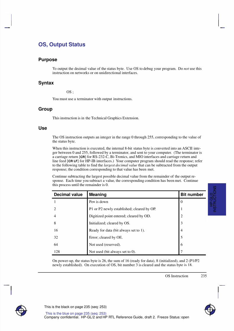
8/12/2019 HPGL2-RTL ReferenceGuide 5961-3526 540pages Sep96
http://slidepdf.com/reader/full/hpgl2-rtl-referenceguide-5961-3526-540pages-sep96 253/539
235
This is the black on page 235 (seq: 253)
Company confidential. HP-GL/2 and HP RTL Reference Guide, draft 2. Freeze Status: open
OS, Output Status
Purpose
To output the decimal value of the status byte. Use OS to debug your program. Do not use thisinstruction on networks or on unidirectional interfaces.
Syntax
OS ;
You must use a terminator with output instructions.
Group
This instruction is in the Technical Graphics Extension.
Use
The OS instruction outputs an integer in the range 0 through 255, corresponding to the value of the status byte.
When this instruction is executed, the internal 8-bit status byte is converted into an ASCII inte-ger between 0 and 255, followed by a terminator, and sent to your computer. (The terminator isa carriage return [] for RS-232-C, Bi-Tronics, and MIO interfaces and carriage return andline feed [ ] for HP-IB interfaces.) Your computer program should read the response; referto the following table to find the largest decimal value that can be subtracted from the outputresponse; the condition corresponding to that value has been met.
Continue subtracting the largest possible decimal value from the remainder of the output re-sponse. Each time you subtract a value, the corresponding condition has been met. Continuethis process until the remainder is 0.
Decimal value Meaning Bit number
1 Pen is down 0
2 P1 or P2 newly established; cleared by OP. 1
4 Digitized point entered; cleared by OD. 2
8 Initialized; cleared by OS. 3
16 Ready for data (bit always set to 1). 432 Error; cleared by OE. 5
64 Not used (reserved). 6
128 Not used (bit always set to 0). 7
On power-up, the status byte is 26, the sum of 16 (ready for data), 8 (initialized), and 2 (P1/P2newly established). On execution of OS, bit number 3 is cleared and the status byte is 18.
This is the blue on page 235 (seq: 253)
OS Instruction
I N S T R U C T I O N S
H P - G L / 2
8/12/2019 HPGL2-RTL ReferenceGuide 5961-3526 540pages Sep96
http://slidepdf.com/reader/full/hpgl2-rtl-referenceguide-5961-3526-540pages-sep96 254/539
236
This is the black on page 236 (seq: 254)
Company confidential. HP-GL/2 and HP RTL Reference Guide, draft 2. Freeze Status: open
See Monitoring the Status Byte on page 91 for further examples of how to use this instruction.
Related Instructions
IN InitializeIP Input P1 and P2IR Input Relative P1 and P2OE Output ErrorOP Output P1 and P2PS Plot Size
Example
The following program outputs the numeric representation of the status byte. Use whateverstatements your computer language requires to perform the input and output operations.
Send to the device: “%–1BBPIN” Enter HP-GL/2 mode, begin a plot, and ini-
tialize HP-GL/2.
Send to the device: “OS;” Output Status.
Read from the device: S.
Print: S.
OS Instruction
8/12/2019 HPGL2-RTL ReferenceGuide 5961-3526 540pages Sep96
http://slidepdf.com/reader/full/hpgl2-rtl-referenceguide-5961-3526-540pages-sep96 255/539
237
This is the black on page 237 (seq: 255)
Company confidential. HP-GL/2 and HP RTL Reference Guide, draft 2. Freeze Status: open
PA, Plot Absolute
Purpose
To establish absolute plotting and moves the pen to the specified absolute coordinates from thecurrent pen position.
Syntax
PA X,Y [,...][;]or
PA [;]
Á Á Á Á Á Á Á
Á Á Á Á Á Á Á
ParameterÁ Á Á Á Á Á Á
Á Á Á Á Á Á Á
FormatÁ Á Á Á Á Á Á Á
Á Á Á Á Á Á Á Á
Functional RangeÁ Á Á Á Á Á Á
Á Á Á Á Á Á Á
Parameter DefaultÁ Á Á Á Á Á Á
Á Á Á Á Á Á Á
Á Á Á Á Á Á Á
X,Y coordinates
Á Á Á Á Á Á Á
Á Á Á Á Á Á Á
Á Á Á Á Á Á Á
current units
Á Á Á Á Á Á Á Á
Á Á Á Á Á Á Á Á
Á Á Á Á Á Á Á Á
device-dependent (at least –223 to 223 – 1)
Á Á Á Á Á Á Á
Á Á Á Á Á Á Á
Á Á Á Á Á Á Á
no default
Group
This instruction is in the Vector Group.
Use
The device interprets the parameters as follows:
No Parameters: Establishes absolute plotting for subsequent instructions.
X,Y coordinates: Specify the absolute location to which the pen moves. When youinclude more than one coordinate pair, the pen moves to each point in the order given,using the current pen up/down status. If the pen is up, PA moves the pen to the point; if thepen is down, PA draws a line to the point. Lines are drawn using the current line width,type, and attributes.
Coordinates are interpreted in current units: as user-units when scaling is on; as plotter-units when scaling is off.
Note: If an odd number of coordinates is specified (in other words, an X coordinate without acorresponding Y coordinate), the device ignores the last unmatched coordinate.
When you use the SM (Symbol Mode) instruction, PA draws the specified symbol at each X,Ycoordinate.
When you use the PM (Polygon Mode) instruction, the X,Y coordinates enter the polygon buff-
er for use when the polygon is edged or filled.
The carriage-return point (see page 66) is moved to the last X,Y.
Related Instructions
PE Polyline EncodedPR Plot RelativePD Pen Down
This is the blue on page 237 (seq: 255)
PA Instruction
I N S T R U C T I O N S
H P - G L / 2
8/12/2019 HPGL2-RTL ReferenceGuide 5961-3526 540pages Sep96
http://slidepdf.com/reader/full/hpgl2-rtl-referenceguide-5961-3526-540pages-sep96 256/539
238
This is the black on page 238 (seq: 256)
Company confidential. HP-GL/2 and HP RTL Reference Guide, draft 2. Freeze Status: open
PU Pen UpLA Line AttributesLT Line Type
PW Pen WidthSM Symbol Mode
Possible Error Conditions
Error Condition Error Number Printer or Plotter Response
Odd number of parameters 2 Unmatched parameter is ignored.
PA Instruction
8/12/2019 HPGL2-RTL ReferenceGuide 5961-3526 540pages Sep96
http://slidepdf.com/reader/full/hpgl2-rtl-referenceguide-5961-3526-540pages-sep96 257/539
239
This is the black on page 239 (seq: 257)
Company confidential. HP-GL/2 and HP RTL Reference Guide, draft 2. Freeze Status: open
PC, Pen Color Assignment
Purpose
To assign colors to specific pens. This instruction is ignored by pen plotters.
Syntax
PC pen,primary1,primary2,primary3[;]or
PC pen[;]or
PC [;]
Á Á Á Á Á Á Á
Á Á Á Á Á Á Á
Parameter Á Á Á Á Á Á Á
Á Á Á Á Á Á Á
Format Á Á Á Á Á Á Á Á
Á Á Á Á Á Á Á Á
Functional Range Á Á Á Á Á Á Á
Á Á Á Á Á Á Á
Parameter Default
Á Á Á Á Á Á Á
Á Á Á Á Á Á Á
pen Á Á Á Á Á Á Á
Á Á Á Á Á Á Á
integer Á Á Á Á Á Á Á Á
Á Á Á Á Á Á Á Á
determined by NP Á Á Á Á Á Á Á
Á Á Á Á Á Á Á
no default
Á Á Á Á Á Á Á
Á Á Á Á Á Á Á
Á Á Á Á Á Á Á
primary1, primary2, primary3
Á Á Á Á Á Á Á
Á Á Á Á Á Á Á
Á Á Á Á Á Á Á
clamped realÁ Á Á Á Á Á Á Á
Á Á Á Á Á Á Á Á
Á Á Á Á Á Á Á Á
determined by CRÁ Á Á Á Á Á Á
Á Á Á Á Á Á Á
Á Á Á Á Á Á Á
(see table below)
Group
This instruction is in the Palette Extension.
Use
With a red/green/blue (RGB) color model, primary1 is red, primary2 is green, and primary3 is
blue.
PC remains in effect until another PC instruction assigns new values for a specific pen or allpens in the palette, or until the device is initialized by the IN instruction. The first eight pensfor color devices default to the colors in the table below, even when the palette is larger thaneight pens. The remaining pen colors are device-dependent. For a monochrome device, 0 de-faults to white; all remaining pen colors default to black.
No parameters: Defaults the colors of all pens as follows:
Number of Pens in Palette Pen Number Color Monochrome
2 (NP2) 0 White White1 Black Black
4 (NP4) 0 White White1 Black Black 2 Red Black 3 Green Black
This is the blue on page 239 (seq: 257)
PC Instruction
I N S T R U C T I O N S
H P - G L / 2
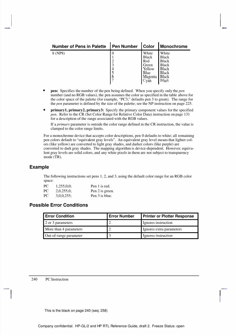
8/12/2019 HPGL2-RTL ReferenceGuide 5961-3526 540pages Sep96
http://slidepdf.com/reader/full/hpgl2-rtl-referenceguide-5961-3526-540pages-sep96 258/539
240
This is the black on page 240 (seq: 258)
Company confidential. HP-GL/2 and HP RTL Reference Guide, draft 2. Freeze Status: open
Number of Pens in Palette MonochromeColorPen Number
8 (NP8) 0 White White
1 Black Black 2 Red Black 3 Green Black 4 Yellow Black 5 Blue Black 6 Magenta Black
yan ac
pen: Specifies the number of the pen being defined. When you specify only the pennumber (and no RGB values), the pen assumes the color as specified in the table above forthe color space of the palette (for example, “PC3;” defaults pen 3 to green). The range forthe pen parameter is defined by the size of the palette; see the NP instruction on page 225.
primary1, primary2, primary3: Specify the primary component values for the specified pen. Refer to the CR (Set Color Range for Relative Color Data) instruction on page 131
for a description of the range associated with the RGB values.
If a primary parameter is outside the color range defined in the CR instruction, the value isclamped to the color range limits.
For a monochrome device that accepts color descriptions, pen 0 defaults to white; all remainingpen colors default to “equivalent gray levels”. An equivalent gray level means that lighter col-ors (like yellow) are converted to light gray shades, and darker colors (like purple) areconverted to dark gray shades. The mapping algorithm is device-dependent. However, equiva-lent gray levels are solid colors, and any white pixels in them are not subject to transparencymode (TR).
Example
The following instructions set pens 1, 2, and 3, using the default color range for an RGB colorspace:
PC 1,255,0,0; Pen 1 is red.
PC 2,0,255,0; Pen 2 is green.
PC 3,0,0,255; Pen 3 is blue.
Possible Error Conditions
Error Condition Error Number Printer or Plotter Response
2 or 3 parameters 2 Ignores instruction
More than 4 parameters 2 Ignores extra parameters
Out-of-range parameter 3 Ignores instruction
PC Instruction
8/12/2019 HPGL2-RTL ReferenceGuide 5961-3526 540pages Sep96
http://slidepdf.com/reader/full/hpgl2-rtl-referenceguide-5961-3526-540pages-sep96 259/539
241
This is the black on page 241 (seq: 259)
Company confidential. HP-GL/2 and HP RTL Reference Guide, draft 2. Freeze Status: open
PD, Pen Down
Purpose
To lower the device’s logical pen and draw subsequent graphics instructions.
Syntax
PD X,Y[,...][;]or
PD [;]
Á Á Á Á Á Á Á
ParameterÁ Á Á Á Á Á Á
FormatÁ Á Á Á Á Á Á Á
Functional RangeÁ Á Á Á Á Á Á
Parameter DefaultÁ Á Á Á Á Á Á
Á
Á Á Á Á Á Á
Á Á Á Á Á Á Á
X,Y coordinates
Á Á Á Á Á Á Á
Á
Á Á Á Á Á Á
Á Á Á Á Á Á Á
current unitsÁ Á Á Á Á Á Á Á
Á
Á Á Á Á Á Á Á
Á Á Á Á Á Á Á Á
device-dependent
(at least –223 to 223 – 1)
Á Á Á Á Á Á Á
Á
Á Á Á Á Á Á
Á Á Á Á Á Á Á
no default
Group
This instruction is in the Vector Group.
Use
On pen plotters, this instruction lowers the pen to draw lines on the page. On other devices itemulates this lowering of the pen, and must be executed before lines can be drawn.
No Parameters: Prepares the device to draw subsequent graphics instructions.
X,Y coordinates or increments: Draws (in current units) to the point specified. You canspecify as many X,Y coordinate pairs as you want. When you include more than onecoordinate pair, the device draws to each point in the order given. Coordinates are inter-preted in current units: as user-units when scaling is on; as plotter-units when scaling is off.
Whether the PD instruction uses coordinates or increments depends on the most recentlyexecuted PA or PR instruction. If no PA or PR instruction is issued, absolute plotting (PA)is used.
The carriage-return point (see page 66) is moved to the last X,Y.
When you use the SM (Symbol Mode) instruction, PD draws the specified symbol at each X,Ycoordinate.
When you use the PM (Polygon Mode) instruction, the X,Y coordinates enter the polygon buff-er (and are used when the polygon is edged or filled).
Note that “PD;PU;” leaves a dot.
This is the blue on page 241 (seq: 259)
PD Instruction
I N S T R U C T I O N S
H P - G L / 2
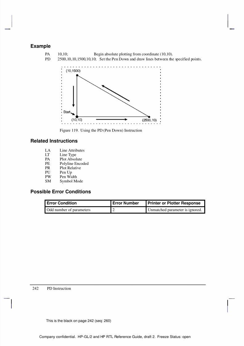
8/12/2019 HPGL2-RTL ReferenceGuide 5961-3526 540pages Sep96
http://slidepdf.com/reader/full/hpgl2-rtl-referenceguide-5961-3526-540pages-sep96 260/539
242
This is the black on page 242 (seq: 260)
Company confidential. HP-GL/2 and HP RTL Reference Guide, draft 2. Freeze Status: open
Example
PA 10,10; Begin absolute plotting from coordinate (10,10).
PD 2500,10,10,1500,10,10; Set the Pen Down and draw lines between the specified points.
Figure 119. Using the PD (Pen Down) Instruction
Related Instructions
LA Line AttributesLT Line TypePA Plot AbsolutePE Polyline EncodedPR Plot RelativePU Pen UpPW Pen Width
SM Symbol Mode
Possible Error Conditions
Error Condition Error Number Printer or Plotter Response
Odd number of parameters 2 Unmatched parameter is ignored.
PD Instruction
8/12/2019 HPGL2-RTL ReferenceGuide 5961-3526 540pages Sep96
http://slidepdf.com/reader/full/hpgl2-rtl-referenceguide-5961-3526-540pages-sep96 261/539
243
This is the black on page 243 (seq: 261)
Company confidential. HP-GL/2 and HP RTL Reference Guide, draft 2. Freeze Status: open
PE, Polyline Encoded
Purpose
To incorporate the PA, PR, PU, PD, and SP instructions into an encrypted format that substan-tially decreases the size of your file and the time required for data transmission. (Thisinstruction is especially useful when using an RS-232-C interface or when you need to mini-mize the file size.)
Syntax
PE [flag[value]]coord_pair...[flag[value]]coord_pair;or
PE ;
Note: Parameter values are self-terminating; do not use commas with this instruction. Also,you must use a semicolon to terminate PE.
Á Á Á Á Á Á Á
ParameterÁ Á Á Á Á Á Á
FormatÁ Á Á Á Á Á Á Á
Functional RangeÁ Á Á Á Á Á Á
Parameter DefaultÁ Á Á Á Á Á Á
Á
Á Á Á Á Á Á
Á Á Á Á Á Á Á
flagÁ Á Á Á Á Á Á
Á
Á Á Á Á Á Á
Á Á Á Á Á Á Á
characterÁ Á Á Á Á Á Á Á
Á
Á Á Á Á Á Á Á
Á Á Á Á Á Á Á Á
‘:’, ‘<’, ‘>’, ‘=’, or ‘7’Á Á Á Á Á Á Á
Á
Á Á Á Á Á Á
Á Á Á Á Á Á Á
no default
Á Á Á Á Á Á Á
Á Á Á Á Á Á Á
valueÁ Á Á Á Á Á Á
Á Á Á Á Á Á Á
characterÁ Á Á Á Á Á Á Á
Á Á Á Á Á Á Á Á
flag-dependent*Á Á Á Á Á Á Á
Á Á Á Á Á Á Á
see below
Á Á Á Á Á Á Á
Á Á Á Á Á Á Á
Á Á Á Á Á Á Á
coord_pair Á Á Á Á Á Á Á
Á Á Á Á Á Á Á
Á Á Á Á Á Á Á
character Á Á Á Á Á Á Á Á
Á Á Á Á Á Á Á Á
Á Á Á Á Á Á Á Á
device-dependent (at least –223 to 223 – 1)
Á Á Á Á Á Á Á
Á Á Á Á Á Á Á
Á Á Á Á Á Á Á
no default
* Refer to the table following the parameter description.
GroupThis instruction is in the Vector Group.
Use
Lines are drawn using the current line type and current units. The device draws to all pointswith the pen down unless a pen up flag precedes the X,Y coordinates. If the final move is madewith the pen up, the pen remains in the up position; otherwise the pen is left in the down posi-tion.
The PE instruction causes the device to interpret coordinate pairs as relative coordinates unlessthey are preceded by an absolute value flag (“=”). Relative integer coordinates produce themost compact data stream. For best results, scale your drawings so you use only integer coordi-
nates and use relative plotting mode. After PE is executed, the previous plotting mode(absolute or relative) is restored. The PE instruction represents vectors in base 64 (default) orbase 32 (explained under Encoding PE Flag Values and X,Y Coordinates). In parameter valuedata, all spaces, delete characters, control characters, as well as ASCII characters 128 through160 and 255 are ignored.
No parameters: Updates the carriage-return point. The PE instruction without parametersdoes not affect the pen’s current location or up/down status.
This is the blue on page 243 (seq: 261)
PE Instruction
I N S T R U C T I O N S
H P - G L / 2
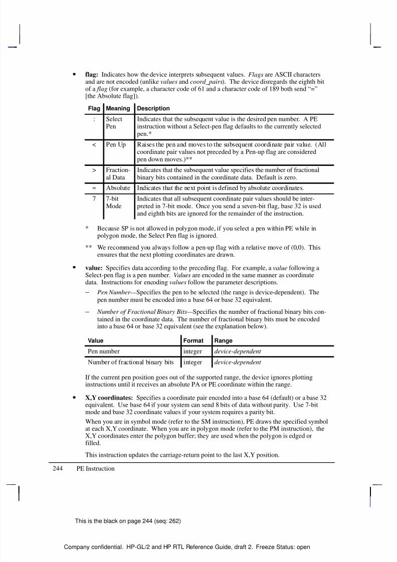
8/12/2019 HPGL2-RTL ReferenceGuide 5961-3526 540pages Sep96
http://slidepdf.com/reader/full/hpgl2-rtl-referenceguide-5961-3526-540pages-sep96 262/539
244
This is the black on page 244 (seq: 262)
Company confidential. HP-GL/2 and HP RTL Reference Guide, draft 2. Freeze Status: open
flag: Indicates how the device interprets subsequent values. Flags are ASCII charactersand are not encoded (unlike values and coord_pairs). The device disregards the eighth bitof a flag (for example, a character code of 61 and a character code of 189 both send “=”
[the Absolute flag]).Flag Meaning Description
: SelectPen
Indicates that the subsequent value is the desired pen number. A PEinstruction without a Select-pen flag defaults to the currently selectedpen.*
< Pen Up Raises the pen and moves to the subsequent coordinate pair value. (Allcoordinate pair values not preceded by a Pen-up flag are consideredpen down moves.)**
> Fraction-al Data
Indicates that the subsequent value specifies the number of fractionalbinary bits contained in the coordinate data. Default is zero.
= Absolute Indicates that the next point is defined by absolute coordinates.
7 7-bitMode
Indicates that all subsequent coordinate pair values should be inter-preted in 7-bit mode. Once you send a seven-bit flag, base 32 is usedand eighth bits are ignored for the remainder of the instruction.
* Because SP is not allowed in polygon mode, if you select a pen within PE while inpolygon mode, the Select Pen flag is ignored.
** We recommend you always follow a pen-up flag with a relative move of (0,0). Thisensures that the next plotting coordinates are drawn.
value: Specifies data according to the preceding flag. For example, a value following aSelect-pen flag is a pen number. Values are encoded in the same manner as coordinatedata. Instructions for encoding values follow the parameter descriptions.
– Pen Number— Specifies the pen to be selected (the range is device-dependent). Thepen number must be encoded into a base 64 or base 32 equivalent.
– Number of Fractional Binary Bits— Specifies the number of fractional binary bits con-tained in the coordinate data. The number of fractional binary bits must be encodedinto a base 64 or base 32 equivalent (see the explanation below).
Value Format Range
Pen number integer device-dependent
Number of fractional binary bits integer device-dependent
If the current pen position goes out of the supported range, the device ignores plottinginstructions until it receives an absolute PA or PE coordinate within the range.
X,Y coordinates: Specifies a coordinate pair encoded into a base 64 (default) or a base 32equivalent. Use base 64 if your system can send 8 bits of data without parity. Use 7-bitmode and base 32 coordinate values if your system requires a parity bit.
When you are in symbol mode (refer to the SM instruction), PE draws the specified symbolat each X,Y coordinate. When you are in polygon mode (refer to the PM instruction), theX,Y coordinates enter the polygon buffer; they are used when the polygon is edged orfilled.
This instruction updates the carriage-return point to the last X,Y position.
PE Instruction
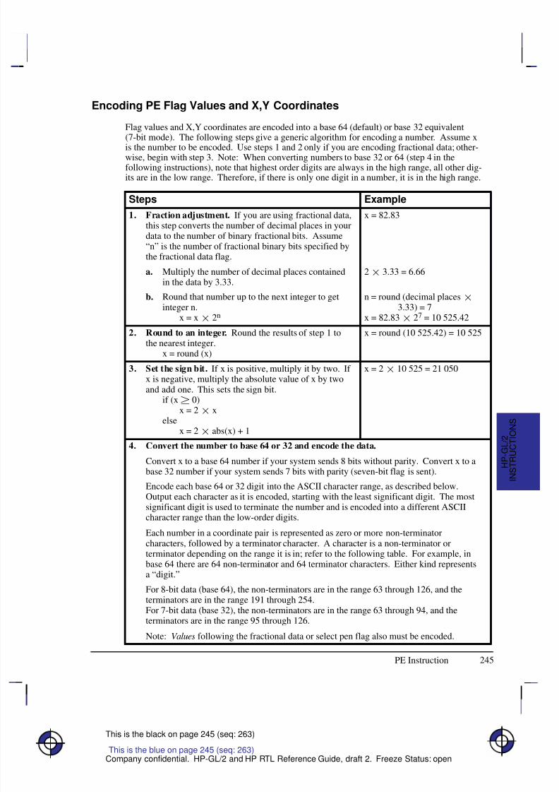
8/12/2019 HPGL2-RTL ReferenceGuide 5961-3526 540pages Sep96
http://slidepdf.com/reader/full/hpgl2-rtl-referenceguide-5961-3526-540pages-sep96 263/539
245
This is the black on page 245 (seq: 263)
Company confidential. HP-GL/2 and HP RTL Reference Guide, draft 2. Freeze Status: open
Encoding PE Flag Values and X,Y Coordinates
Flag values and X,Y coordinates are encoded into a base 64 (default) or base 32 equivalent
(7-bit mode). The following steps give a generic algorithm for encoding a number. Assume xis the number to be encoded. Use steps 1 and 2 only if you are encoding fractional data; other-wise, begin with step 3. Note: When converting numbers to base 32 or 64 (step 4 in thefollowing instructions), note that highest order digits are always in the high range, all other dig-its are in the low range. Therefore, if there is only one digit in a number, it is in the high range.
Steps Example
1. Fraction adjustment. If you are using fractional data,this step converts the number of decimal places in yourdata to the number of binary fractional bits. Assume“n” is the number of fractional binary bits specified bythe fractional data flag.
x = 82.83
a. Multiply the number of decimal places containedin the data by 3.33.
2 3.33 = 6.66
b. Round that number up to the next integer to getinteger n.
x = x 2n
n = round (decimal places 3.33) = 7
x = 82.83 27 = 10 525.42
2. Round to an integer. Round the results of step 1 tothe nearest integer.
x = round (x)
x = round (10 525.42) = 10 525
3. Set the sign bit. If x is positive, multiply it by two. If x is negative, multiply the absolute value of x by twoand add one. This sets the sign bit.
if (x 0)x = 2 x
elsex = 2 abs(x) + 1
x = 2 10 525 = 21 050
4. Convert the number to base 64 or 32 and encode the data.
Convert x to a base 64 number if your system sends 8 bits without parity. Convert x to abase 32 number if your system sends 7 bits with parity (seven-bit flag is sent).
Encode each base 64 or 32 digit into the ASCII character range, as described below.Output each character as it is encoded, starting with the least significant digit. The mostsignificant digit is used to terminate the number and is encoded into a different ASCIIcharacter range than the low-order digits.
Each number in a coordinate pair is represented as zero or more non-terminatorcharacters, followed by a terminator character. A character is a non-terminator or
terminator depending on the range it is in; refer to the following table. For example, inbase 64 there are 64 non-terminator and 64 terminator characters. Either kind representsa “digit.”
For 8-bit data (base 64), the non-terminators are in the range 63 through 126, and theterminators are in the range 191 through 254.For 7-bit data (base 32), the non-terminators are in the range 63 through 94, and theterminators are in the range 95 through 126.
Note: Values following the fractional data or select pen flag also must be encoded.
This is the blue on page 245 (seq: 263)
PE Instruction
I N S T R U C T I O N S
H P - G L / 2
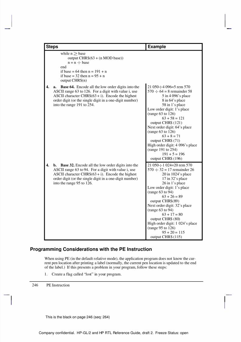
8/12/2019 HPGL2-RTL ReferenceGuide 5961-3526 540pages Sep96
http://slidepdf.com/reader/full/hpgl2-rtl-referenceguide-5961-3526-540pages-sep96 264/539
246
This is the black on page 246 (seq: 264)
Company confidential. HP-GL/2 and HP RTL Reference Guide, draft 2. Freeze Status: open
Steps Example
while n base
output CHR$(63 + (n MOD base))n = n baseendif base = 64 then n = 191 + nif base = 32 then n = 95 + noutput CHR$(n)
4. a. Base 64. Encode all the low order digits into theASCII range 63 to 126. For a digit with value i, useASCII character CHR$(63 + i). Encode the highestorder digit (or the single digit in a one-digit number)into the range 191 to 254.
21 0504 096=5 rem 570570 64 = 8 remainder 58
5 in 4 096’s place8 in 64’s place58 in 1’s place
Low order digit: 1’s place(range 63 to 126)
63 + 58 = 121 output CHR$ (121)Next order digit: 64’s place(range 63 to 126)
63 + 8 = 71 output CHR$ (71)High order digit: 4 096’s place(range 191 to 254)
191 + 5 = 196 output CHR$ (196)
4. b. Base 32. Encode all the low order digits into theASCII range 63 to 94. For a digit with value i, useASCII character CHR$(63 + i). Encode the highest
order digit (or the single digit in a one-digit number)into the range 95 to 126.
21 0501 024=20 rem 570570 32 = 17 remainder 26
20 in 1024’s place
17 in 32’s place26 in 1’s placeLow order digit: 1’s place(range 63 to 94)
63 + 26 = 89 output CHR$(89)Next order digit: 32’s place(range 63 to 94)
63 + 17 = 80 output CHR$ (80)High order digit: 1 024’s place(range 95 to 126)
95 + 20 = 115 output CHR$ (115)
Programming Considerations with the PE Instruction
When using PE (in the default relative mode), the application program does not know the cur-rent pen location after printing a label (normally, the current pen location is updated to the endof the label.) If this presents a problem in your program, follow these steps:
1. Create a flag called “lost” in your program.
PE Instruction
8/12/2019 HPGL2-RTL ReferenceGuide 5961-3526 540pages Sep96
http://slidepdf.com/reader/full/hpgl2-rtl-referenceguide-5961-3526-540pages-sep96 265/539
247
This is the black on page 247 (seq: 265)
Company confidential. HP-GL/2 and HP RTL Reference Guide, draft 2. Freeze Status: open
Note: At the beginning of your application program, set “lost” to “true”. Then, specify thenext coordinate in absolute mode (PA or PE=).
2. After labeling (or any instruction which updates the current pen location), set “lost” to
“true”.
3. If “lost” = “true” at the beginning of the PE instruction, use an Absolute flag for the firstcoordinate pair only (subsequent coordinates are interpreted as relative).
4. Set “lost” to “false”.
When you are converting and encoding data, note the following:
n 64. You can optimize your application by shifting six bits to the right, since shifting isnormally faster than division.
n MOD 64. The number can be logically AND’d with 63, also for improved performance.
Example
The following partial program converts three relative real coordinates to base 64:
Prompt user: “Input number of fractional decimal places in data”.
Read the response into: F (in this example, 2 decimal places).
Calculate Number of Fractional Binary Bits.
F = F * 3.33
F = INT(F) INT is the integer function.
A = F
IF F 0 THEN F = 2*ABS(F) ELSE F = 2*ABS(F)+1
F = 191+F
Send to the device: “PE>”+CHR$(F) (using BASIC language notation)
Convert coordinate data to base 64
FOR J = 1 to 6 READ C
C = C * (2^A) (^ is the exponential function)
C = INT(C)
IF C 0 THEN C = 2*C ELSE C = 2*ABS(C)+1
WHILE C 64
Send to the device: CHR$(63+(C MOD 64))
C = C 64
End WHILE
C = 191+C
Send to the device: CHR$(C)
NEXT J
Send to the device: “;”Typical data for this program might be: 10.58,0,–5.58,10.67,–5,–10.67
This is the blue on page 247 (seq: 265)
PE Instruction
I N S T R U C T I O N S
H P - G L / 2
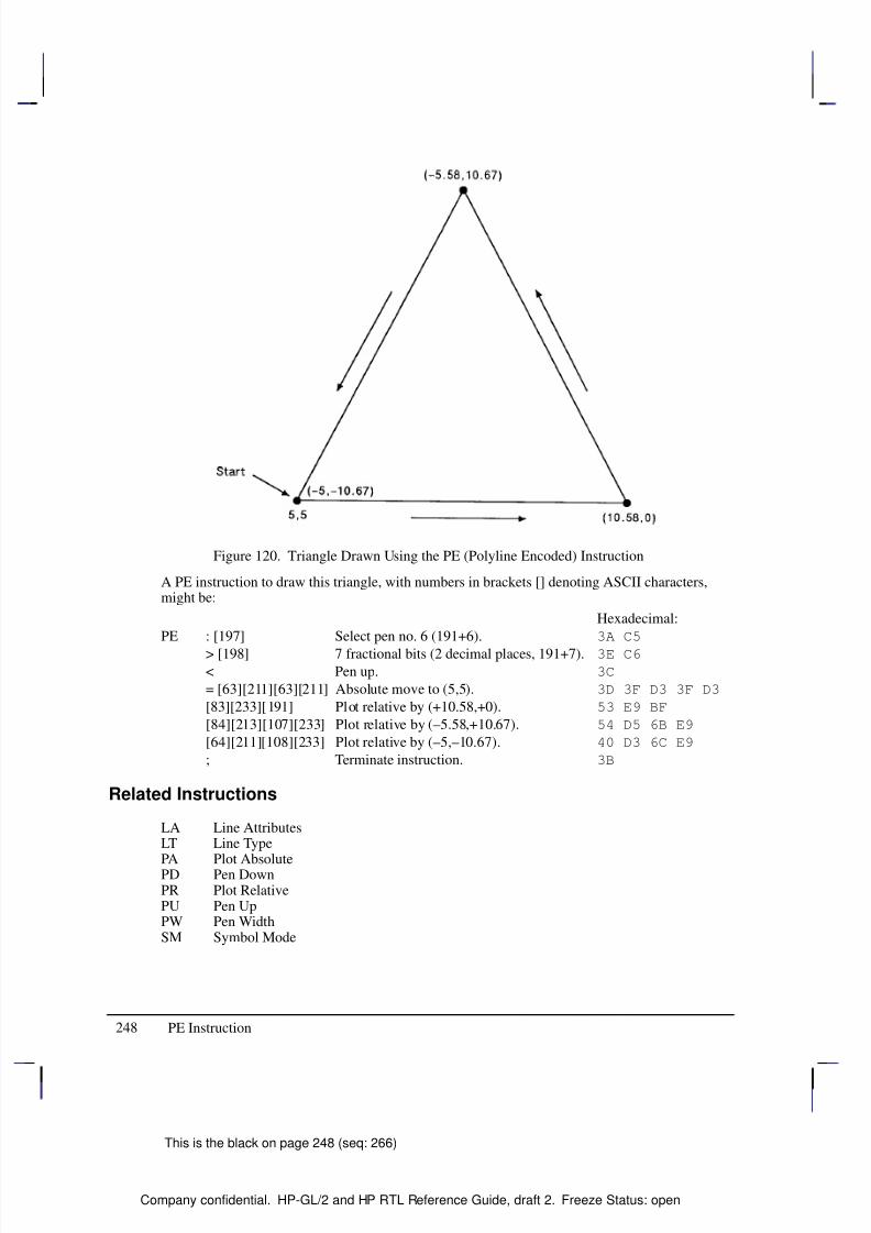
8/12/2019 HPGL2-RTL ReferenceGuide 5961-3526 540pages Sep96
http://slidepdf.com/reader/full/hpgl2-rtl-referenceguide-5961-3526-540pages-sep96 266/539
248
This is the black on page 248 (seq: 266)
Company confidential. HP-GL/2 and HP RTL Reference Guide, draft 2. Freeze Status: open
Figure 120. Triangle Drawn Using the PE (Polyline Encoded) Instruction
A PE instruction to draw this triangle, with numbers in brackets [] denoting ASCII characters,might be:
Hexadecimal:
PE : [197] Select pen no. 6 (191+6). 3A C5
> [198] 7 fractional bits (2 decimal places, 191+7). 3E C6
< Pen up. 3C
= [63][211][63][211] Absolute move to (5,5). 3D 3F D3 3F D3
[83][233][191] Plot relative by (+10.58,+0). 53 E9 BF
[84][213][107][233] Plot relative by (–5.58,+10.67). 54 D5 6B E9
[64][211][108][233] Plot relative by (–5,–10.67). 40 D3 6C E9
; Terminate instruction. 3B
Related Instructions
LA Line AttributesLT Line Type
PA Plot AbsolutePD Pen DownPR Plot RelativePU Pen UpPW Pen WidthSM Symbol Mode
PE Instruction
8/12/2019 HPGL2-RTL ReferenceGuide 5961-3526 540pages Sep96
http://slidepdf.com/reader/full/hpgl2-rtl-referenceguide-5961-3526-540pages-sep96 267/539
249
This is the black on page 249 (seq: 267)
Company confidential. HP-GL/2 and HP RTL Reference Guide, draft 2. Freeze Status: open
PG, Advance Full Page
Purpose
For devices with page advance capability: to terminate the plot being sent, to draw it, and toadvance the page.
For devices without page advance capability: If the media has been plotted on, to perform thefunction of the NR (Not Ready) instruction (see page 227).
On PCL devices with HP-GL/2 capability, this instruction is ignored (see Using PG in a PCL Dual-Context Environment below).
Syntax
PG n[;] orPG [;]
The PG instruction, with or without parameters, must be terminated with a semicolon, unless itis immediately followed by the RP (Replot) instruction (see page 279).
Á Á Á Á Á Á Á
Á Á Á Á Á Á Á
Parameter Á Á Á Á Á Á Á
Á Á Á Á Á Á Á
Format Á Á Á Á Á Á Á Á
Á Á Á Á Á Á Á Á
Functional Range Á Á Á Á Á Á Á
Á Á Á Á Á Á Á
Parameter Default
Á Á Á Á Á Á Á
Á Á Á Á Á Á Á
n Á Á Á Á Á Á Á
Á Á Á Á Á Á Á
clamped integer Á Á Á Á Á Á Á Á
Á Á Á Á Á Á Á Á
–32 768 to 32 767 Á Á Á Á Á Á Á
Á Á Á Á Á Á Á
no parameter
Group
This instruction is in the Configuration and Status Group.
Use
Some devices require an end-of-file marker to designate the end of incoming data. The PGinstruction is a common marker for HP-GL/2 devices (the RP instruction is another). When thePG instruction is received, the plot is drawn and the page is ejected. If the plotter expects butdoes not receive the PG instruction, it will wait for user interaction through the control panelbefore it draws the plot.
PG moves the current pen location to the lower-left corner of the hard-clip limits on the nextpage, raises the pen, and retains the current plotting mode (relative or absolute). PG does notaffect P1 and P2 values or plot rotation.
No Parameter: Advances the page only if you have plotted on the current page. This is
the recommended method of using the PG instruction.
n: Advances the page whether or not you have plotted on the media.
The current plot remains stored after a page eject until an instruction is received that marks thepage or adds edges in the polygon buffer.
PG clears the current pattern residue and terminates any continuous vector sequence (see theLA and LT instructions).
This is the blue on page 249 (seq: 267)
PG Instruction
I N S T R U C T I O N S
H P - G L / 2
8/12/2019 HPGL2-RTL ReferenceGuide 5961-3526 540pages Sep96
http://slidepdf.com/reader/full/hpgl2-rtl-referenceguide-5961-3526-540pages-sep96 268/539
250
This is the black on page 250 (seq: 268)
Company confidential. HP-GL/2 and HP RTL Reference Guide, draft 2. Freeze Status: open
Using PG in a PCL Dual-Context Environment
PG is ignored in PCL. A page eject is possible only can only be accomplished by the form feed
() control character. A form feed causes an unconditional page eject and advances the cur-rent active position to the same horizontal position at the top of the next form (top margin).Note that the HP-GL/2 pen position is not affected by a form feed; it occupies the same positionon the next page. A PCL reset, page length, page size, orientation, or input cassette controlinstruction causes a conditional page eject. When a page is ejected, the PCL cursor is set to the“home position” (at the left and top margin) on the new page. A page eject caused by a PCLcommand does not effect the HP-GL/2 cursor position.
This HP-GL/2 instruction is ignored by the device since it could cause undesirable results whenimporting plots. A page eject can be accomplished only from the PCL printer language mode.
In an HP RTL dual-context environment, an E (Reset) command performs the PG func-tion; a form feed () character is ignored.
Related Instructions
BP Begin PlotPS Plot SizeRP Replot
PG Instruction
8/12/2019 HPGL2-RTL ReferenceGuide 5961-3526 540pages Sep96
http://slidepdf.com/reader/full/hpgl2-rtl-referenceguide-5961-3526-540pages-sep96 269/539
251
This is the black on page 251 (seq: 269)
Company confidential. HP-GL/2 and HP RTL Reference Guide, draft 2. Freeze Status: open
PM, Polygon Mode
Purpose
To enter polygon mode for defining shapes, such as block letters or any unique area, and exitsfor subsequent filling or edging. Fill polygons using the FP (Fill Polygon) instruction or outlinethem using the EP (Edge Polygon) instruction.
Syntax
PM polygon_definition [;]or
PM [;]
Á Á Á Á Á Á Á
Á Á Á Á Á Á Á
Parameter Á Á Á Á Á Á Á
Á Á Á Á Á Á Á
Format Á Á Á Á Á Á Á Á
Á Á Á Á Á Á Á Á
Functional Range Á Á Á Á Á Á Á
Á Á Á Á Á Á Á
Parameter Default
Á Á Á Á Á Á Á
Á Á Á Á Á Á Á
polygon_definitionÁ Á Á Á Á Á Á
Á Á Á Á Á Á Á
clamped integer Á Á Á Á Á Á Á Á
Á Á Á Á Á Á Á Á
0, 1, and 2 Á Á Á Á Á Á Á
Á Á Á Á Á Á Á
0
Group
This instruction is in the Polygon Group.
Use
In polygon mode, you define the area of the polygon(s) using graphics instructions. Theseinstructions (and associated X,Y coordinates) are stored in the polygon buffer. The polygon isnot drawn until you exit polygon mode and fill or outline the area.
No Parameters: Clears the polygon buffer and enters polygon mode. Equivalent to“PM0”.
polygon_definition: Defines polygon mode status as follows.
0 Clears the polygon buffer and enters polygon mode.
1 Closes the current polygon (or subpolygon) with a pen-up edge, and remains inpolygon mode; all instructions sent following PM1 but before a PM2 (or the nextPM1) are stored as one subpolygon.
2 Closes current polygon (or subpolygon) and exits polygon mode.
The following paragraphs explain how to use each parameter. The order in which you use theseinstructions is very important. “PM1” and “PM2” are ignored if not preceded by “PM0”.
“PM0” or “PM”
Use “PM0” to clear the polygon buffer and enter polygon mode. While in polygon mode, onlycertain instructions are allowed, as follows:
AA Arc AbsoluteAR Arc RelativeAT Absolute Arc Three Point
This is the blue on page 251 (seq: 269)
PM Instruction
I N S T R U C T I O N S
H P - G L / 2
8/12/2019 HPGL2-RTL ReferenceGuide 5961-3526 540pages Sep96
http://slidepdf.com/reader/full/hpgl2-rtl-referenceguide-5961-3526-540pages-sep96 270/539
252
This is the black on page 252 (seq: 270)
Company confidential. HP-GL/2 and HP RTL Reference Guide, draft 2. Freeze Status: open
BP Begin Plot (this instruction automatically closes polygon mode and initializes thedevice)
BR Bezier Relative
BZ Bezier AbsoluteCI CircleCO CommentDF Default Values (this instruction automatically closes polygon mode and applies
defaults to the device)IN Initialize (this instruction automatically closes polygon mode and initializes the
device)PA Plot AbsolutePD Pen DownPE Polyline EncodedPM1/PM2 Polygon ModePR Plot RelativePU Pen UpRT Relative Arc Three Point
The polygon buffer stores the lines (vectors) that define your polygon. These vectors are ac-cessed later when you exit polygon mode and fill or edge the polygon.
Note: While in polygon mode, the CI instruction is interpreted differently than other graphicsinstructions. Refer to Drawing Circles in Polygon Mode on page 52 for more details. Whenyou use the PE instruction in polygon mode, you cannot change pens; any new pen selection isignored.
When you define a polygon, the pen location before the “PM0” instruction is the first point(vertex) of the polygon, and the first point stored in the polygon buffer. For example, if youexecute the instructions “PA0,1750;PM0”, the absolute coordinates (0,1750) specify the firstpoint of your polygon. Each subsequent pair of coordinates defines a point, or vertex, of thepolygon.
You can define points with the pen up or down. However, the EP instruction only draws be-tween points that are defined when the pen is down. On the other hand, the FP instruction fillsthe area(s) between all vertices, regardless of whether the pen is up or down when the verticesare defined.
It is good programming practice to “close” the polygon before exiting polygon mode. Closinga polygon means adding the final vertex that defines a continuous shape; the last coordinates orincrements represent the same location as the first. If you have not closed the polygon, execut-ing “PM1” or “PM2” forces closure by adding a point to close the polygon.
You can also use the IN (Initialize) or DF (Default Values) instructions while in polygon mode.Both instructions exit polygon mode, clear the polygon buffer, and begin executing subsequentinstructions immediately. Output instructions can also be used; they are not stored in the poly-gon buffer, but are executed immediately. You must exit polygon mode to execute otherHP-GL/2 graphics instructions.
“PM1”
Use “PM1” to close the current polygon (or subpolygon) and remain in polygon mode; the de-vice adds a closure point if necessary. When you use “PM1”, the point after “PM1” becomesthe first point of the next subpolygon. This move is not used as a boundary when filling a poly-gon with FP. When drawing the polygon, the pen always moves to this point in the up position,
PM Instruction
8/12/2019 HPGL2-RTL ReferenceGuide 5961-3526 540pages Sep96
http://slidepdf.com/reader/full/hpgl2-rtl-referenceguide-5961-3526-540pages-sep96 271/539
253
This is the black on page 253 (seq: 271)
Company confidential. HP-GL/2 and HP RTL Reference Guide, draft 2. Freeze Status: open
regardless of the current pen status. Each subsequent coordinate pair after “PM1” defines apoint of the subpolygon.
With the exception of the first chord in AA, AR, AT, and RT, this point is treated as a pen-upmove regardless of the current pen state. All subsequent points become vertices of the subpoly-gon until “PM1” or “PM2”. “PM1” adds a point to implicitly close a polygon that has notalready been explicitly closed.
“PM2”
Use “PM2” to close the current polygon (or subpolygon) and exit polygon mode. Remember, if you have not closed your polygon, executing “PM2” adds a point to close the polygon. Referto Pen Location on page 23.
After you exit polygon mode, the EP (Edge Polygon) or FP (Fill Polygon) instructions draw thepolygon. Although points may be defined with the pen up or down, EP draws only between
points defined with the pen down, while FP fills the areas between all defined points.A polygon with fewer than three points is not drawn; it is not filled by FP nor edged by EP.This syntactical incompleteness is different from when a polygon is correctly specified but geo-metrically degenerate (for example, a polygon limited to coincident points is rendered as a dot,and one limited to collinear points is rendered as a line).
A point added by implicit closure counts as one of the three points. If a complex polygon con-tains a dot (a zero-dimension subpolygon), enough points must be specified (for example, by“PR0,0;”) to have three upon closure.
Using PM in a Dual-Context Environment
E is also recognized in polygon mode. It causes the device to exit polygon mode, clear the
polygon buffer, exit HP-GL/2 mode, and eject a page. Sending an E while in polygonmode is not recommended, but it performs an important function (allowing you to recover froma previous job that left the device in polygon mode).
Example
The following example draws the surface area of a 3-prong electrical receptacle as a series of subpolygons, then fills and edges it using the FP and EP instructions, respectively.
PA 2000,2000; Specify absolute plotting and move to (2000,2000).
PM 0; Enter polygon mode.
PD 3000,2000,3000,3000; Store a Pen Down instruction, and store locations (3000,2000)
and (3000,3000).
PD 2000,3000,2000,2000; Store two more pen-down locations, (2000,3000) and
(2000,2000).
PM 1; Close the first polygon (the outer square).
PD 2080,2160,2480,2160, 2480,2340,2080,2340,2080,2160; Store 5 pen-down locations
for a subpolygon.
PM 1; Close the subpolygon (the lower rectangle).
PD 2080,2660,2480,2660,2480,2840,2080,2840,2080,2660; Store pen-down locations for
another subpolygon.
PM 1; Close the second subpolygon (the upper rectangle).
PM Instruction
I N S T R U C T I O N S
H P - G L / 2
This is the blue on page 253 (seq: 271)
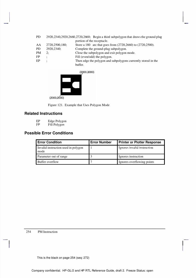
8/12/2019 HPGL2-RTL ReferenceGuide 5961-3526 540pages Sep96
http://slidepdf.com/reader/full/hpgl2-rtl-referenceguide-5961-3526-540pages-sep96 272/539
254
This is the black on page 254 (seq: 272)
Company confidential. HP-GL/2 and HP RTL Reference Guide, draft 2. Freeze Status: open
PD 2920,2340,2920,2660,2720,2660; Begin a third subpolygon that draws the ground plug
portion of the receptacle.
AA 2720,2500,180; Store a 180 arc that goes from (2720,2660) to (2720,2500).
PD 2920,2340; Complete the ground-plug subpolygon.PM 2; Close the subpolygon and exit polygon mode.
FP ; Fill (even/odd) the polygon.
EP ; Then edge the polygon and subpolygons currently stored in the
buffer.
Figure 121. Example that Uses Polygon Mode
Related Instructions
EP Edge PolygonFP Fill Polygon
Possible Error Conditions
Error Condition Error Number Printer or Plotter Response
Invalid instruction used in polygonmode
1 Ignores invalid instruction
Parameter out of range 3 Ignores instruction
Buffer overflow 7 Ignores overflowing points
PM Instruction
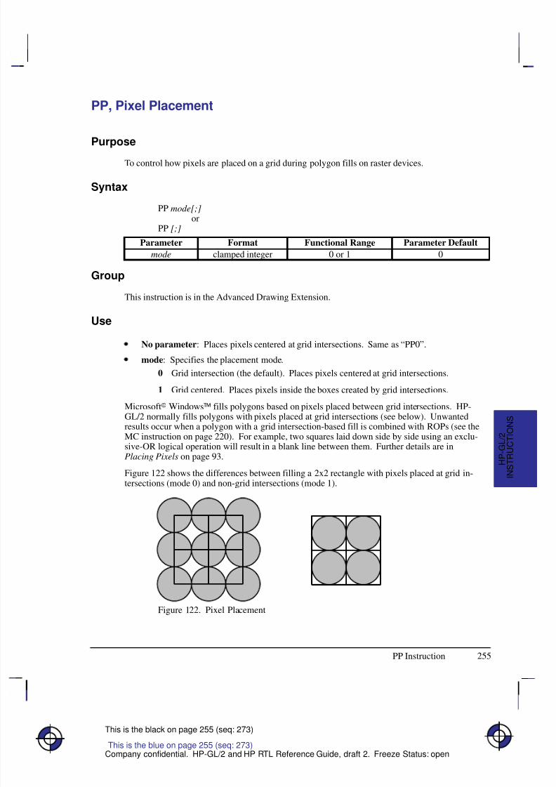
8/12/2019 HPGL2-RTL ReferenceGuide 5961-3526 540pages Sep96
http://slidepdf.com/reader/full/hpgl2-rtl-referenceguide-5961-3526-540pages-sep96 273/539
255
This is the black on page 255 (seq: 273)
Company confidential. HP-GL/2 and HP RTL Reference Guide, draft 2. Freeze Status: open
PP, Pixel Placement
Purpose
To control how pixels are placed on a grid during polygon fills on raster devices.
Syntax
PP mode[;]or
PP [;]
Á Á Á Á Á Á
Á Á Á Á Á Á
Parameter Á Á Á Á Á Á Á
Á Á Á Á Á Á Á
Format Á Á Á Á Á Á Á Á Á
Á Á Á Á Á Á Á Á Á
Functional Range Á Á Á Á Á Á Á Á
Á Á Á Á Á Á Á Á
Parameter Default
Á Á Á Á Á Á
Á Á Á Á Á Á
mode Á Á Á Á Á Á Á
Á Á Á Á Á Á Á
clamped integer Á Á Á Á Á Á Á Á Á
Á Á Á Á Á Á Á Á Á
0 or 1 Á Á Á Á Á Á Á Á
Á Á Á Á Á Á Á Á
0
Group
This instruction is in the Advanced Drawing Extension.
Use
No parameter: Places pixels centered at grid intersections. Same as “PP0”.
mode: Specifies the placement mode.
0 Grid intersection (the default). Places pixels centered at grid intersections.
1 Grid centered. Places pixels inside the boxes created by grid intersections.
Microsoft Windows™ fills polygons based on pixels placed between grid intersections. HP-
GL/2 normally fills polygons with pixels placed at grid intersections (see below). Unwantedresults occur when a polygon with a grid intersection-based fill is combined with ROPs (see theMC instruction on page 220). For example, two squares laid down side by side using an exclu-sive-OR logical operation will result in a blank line between them. Further details are inPlacing Pixels on page 93.
Figure 122 shows the differences between filling a 2x2 rectangle with pixels placed at grid in-tersections (mode 0) and non-grid intersections (mode 1).
Figure 122. Pixel Placement
This is the blue on page 255 (seq: 273)
PP Instruction
I N S T R U C T I O N S
H P - G L / 2

8/12/2019 HPGL2-RTL ReferenceGuide 5961-3526 540pages Sep96
http://slidepdf.com/reader/full/hpgl2-rtl-referenceguide-5961-3526-540pages-sep96 274/539
256
This is the black on page 256 (seq: 274)
Company confidential. HP-GL/2 and HP RTL Reference Guide, draft 2. Freeze Status: open
“PP1” decreases by one pixel the height and the width of the trapezoids formed by decomposi-tion. “PP0” renders portions that are zero height or width as lines, and portions that are bothzero length and width as dots. “PP1” does not render portions that are zero height or width.
Note that pixel placement is applied after the soft-clip window is established, so pixels may besubject to clipping.
Possible Error Conditions
Error Condition Error Number Printer or Plotter Response
Any mode value other than 0 or 1. 3 Ignores instruction
PP Instruction
8/12/2019 HPGL2-RTL ReferenceGuide 5961-3526 540pages Sep96
http://slidepdf.com/reader/full/hpgl2-rtl-referenceguide-5961-3526-540pages-sep96 275/539
257
This is the black on page 257 (seq: 275)
Company confidential. HP-GL/2 and HP RTL Reference Guide, draft 2. Freeze Status: open
PR, Plot Relative
Purpose
To establish relative plotting and move the pen to specified points, with each move relative tothe current pen location.
Syntax
PR X,Y[,...;]or
PR [;]
Á Á Á Á Á Á Á
Á Á Á Á Á Á Á
ParameterÁ Á Á Á Á Á Á
Á Á Á Á Á Á Á
FormatÁ Á Á Á Á Á Á Á
Á Á Á Á Á Á Á Á
Functional RangeÁ Á Á Á Á Á Á
Á Á Á Á Á Á Á
Parameter DefaultÁ Á Á Á Á Á Á
Á Á Á Á Á Á Á
Á Á Á Á Á Á Á
X,Y increments
Á Á Á Á Á Á Á
Á Á Á Á Á Á Á
Á Á Á Á Á Á Á
current units
Á Á Á Á Á Á Á Á
Á Á Á Á Á Á Á Á
Á Á Á Á Á Á Á Á
device-dependent (at least –223 to 223 – 1)
Á Á Á Á Á Á Á
Á Á Á Á Á Á Á
Á Á Á Á Á Á Á
no default
Group
This instruction is in the Vector Group.
Use
The device interprets the parameters as follows:
No Parameters: Defaults to relative plotting mode for subsequent instructions.
X, Y (increments): Specify incremental moves relative to the current pen location. Whenyou include more than one relative coordinate pair, the pen moves to each point in theorder given (relative to the previous point), using the current pen up/down status.
The carriage-return point (see page 66) is moved to the last X,Y.
If the pen is up, PR moves the pen to the point; if the pen is down, PR draws a line to the point.Lines are drawn using the current line width, type, and attributes.
When you use the SM (Symbol Mode) instruction, PR draws the specified symbol at each X,Ycoordinate. When you use the PM (Polygon Mode) instruction, the X,Y coordinates enter thepolygon buffer (and are used when the polygon is edged or filled).
Coordinates are interpreted in current units: as user-units when scaling is on; as plotter-unitswhen scaling is off.
Related Instructions
LA Line AttributesLT Line TypePA Plot AbsolutePD Pen DownPE Polyline EncodedPW Pen WidthSM Symbol Mode
This is the blue on page 257 (seq: 275)
PR Instruction
I N S T R U C T I O N S
H P - G L / 2
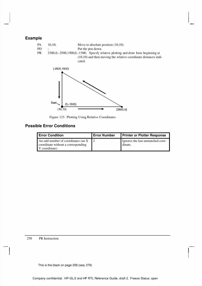
8/12/2019 HPGL2-RTL ReferenceGuide 5961-3526 540pages Sep96
http://slidepdf.com/reader/full/hpgl2-rtl-referenceguide-5961-3526-540pages-sep96 276/539
258
This is the black on page 258 (seq: 276)
Company confidential. HP-GL/2 and HP RTL Reference Guide, draft 2. Freeze Status: open
Example
PA 10,10; Move to absolute position (10,10).
PD ; Put the pen down.PR 2500,0,–2500,1500,0,–1500; Specify relative plotting and draw lines beginning at
(10,10) and then moving the relative coordinate distances indi-
cated.
Figure 123. Plotting Using Relative Coordinates
Possible Error Conditions
Error Condition Error Number Printer or Plotter Response
An odd number of coordinates (an Xcoordinate without a correspondingY coordinate)
2 Ignores the last unmatched coor-dinate.
PR Instruction
8/12/2019 HPGL2-RTL ReferenceGuide 5961-3526 540pages Sep96
http://slidepdf.com/reader/full/hpgl2-rtl-referenceguide-5961-3526-540pages-sep96 277/539
259
This is the black on page 259 (seq: 277)
Company confidential. HP-GL/2 and HP RTL Reference Guide, draft 2. Freeze Status: open
PS, Plot Size
Purpose
To set the hard-clip limits to a given size. Use PS to simplify long-axis plotting or to minimizepaper waste when drawing small plots. This is especially useful for plotters with roll-feed me-dia. When used, this instruction must appear in the picture header information (see page 78).
Syntax
PS length[,width][;]or
PS [;]
Á Á Á Á Á Á Á
Á Á Á Á Á Á Á
Parameter Á Á Á Á Á Á Á
Á Á Á Á Á Á Á
Format Á Á Á Á Á Á Á Á
Á Á Á Á Á Á Á Á
Functional Range Á Á Á Á Á Á Á
Á Á Á Á Á Á Á
Parameter Default
Á Á Á Á Á Á Á
Á Á Á Á Á Á Á
length Á Á Á Á Á Á Á
Á Á Á Á Á Á Á
integer Á Á Á Á Á Á Á Á
Á Á Á Á Á Á Á Á
device-dependent Á Á Á Á Á Á Á
Á Á Á Á Á Á Á
hard-clip limits*
Á Á Á Á Á Á Á
Á Á Á Á Á Á Á
widthÁ Á Á Á Á Á Á
Á Á Á Á Á Á Á
integerÁ Á Á Á Á Á Á Á
Á Á Á Á Á Á Á Á
device-dependent Á Á Á Á Á Á Á
Á Á Á Á Á Á Á
hard-clip limits*
* The default length and width for single-sheet media is the hard-clip limits; for roll-feedmedia the default length is approximately 1.5 times the media width.
Group
This instruction is in the Technical Graphics Extension.
Use
Send PS immediately after the BP (Begin Plot) or IN (Initialize) instruction (IN defaults PS if the device is in picture header state [see page 78], that is no marks have been made on the me-dia) and before any drawing instructions. DF (Default Values) does not default PS. Note thatthe entire plot must be done within the scope of a single PS instruction; you cannot change theplot size in the middle of a plot.
No Parameters: Defaults the plot length and width to the hard-clip limits (the maximumprintable area).
length: Establishes a new length, in plotter-units, of the hard-clip limits. The lengthalways corresponds to the direction of the plot frame advance. Refer to the documentationfor your device or HP-GL/2 option for the maximum length of a single plot. If the lengthis less than or equal to 0, the device ignores the instruction.
width: Establishes the new width, in plotter-units, of the hard-clip limits. The width isalways the horizontal direction. If the width is less than or equal to 0, the device ignoresthe instruction.
If you specify a plot size larger than your media’s maximum plotting area, your plot size isclamped to the hard-clip limits. Figure 124 indicates how PS orients the default coordinatesystem according to the length and width after clamping. The default origin defines the lower-left corner of the hard-clip limits and is always located on the side of the plot frame oppositethe next plot frame.
This is the blue on page 259 (seq: 277)
PS Instruction
I N S T R U C T I O N S
H P - G L / 2
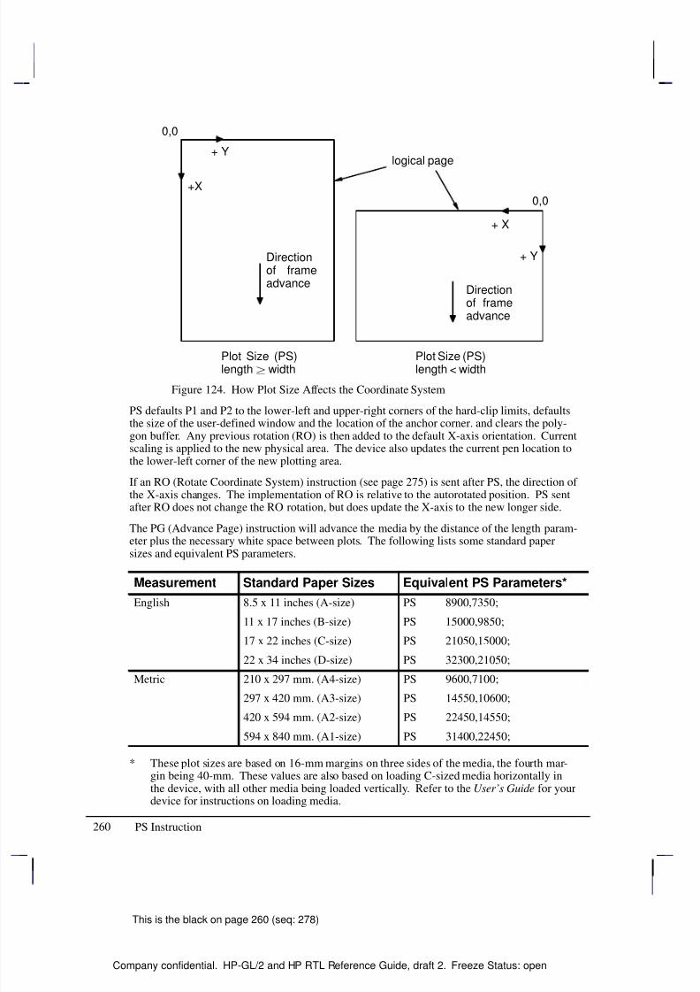
8/12/2019 HPGL2-RTL ReferenceGuide 5961-3526 540pages Sep96
http://slidepdf.com/reader/full/hpgl2-rtl-referenceguide-5961-3526-540pages-sep96 278/539
260
This is the black on page 260 (seq: 278)
Company confidential. HP-GL/2 and HP RTL Reference Guide, draft 2. Freeze Status: open
+X
0,0
0,0
Plot Size (PS)length width
Plot Size (PS)length < width
+ Y
+ X
+ YDirectionof frameadvance
Directionof frameadvance
logical page
Figure 124. How Plot Size Affects the Coordinate System
PS defaults P1 and P2 to the lower-left and upper-right corners of the hard-clip limits, defaultsthe size of the user-defined window and the location of the anchor corner. and clears the poly-gon buffer. Any previous rotation (RO) is then added to the default X-axis orientation. Currentscaling is applied to the new physical area. The device also updates the current pen location tothe lower-left corner of the new plotting area.
If an RO (Rotate Coordinate System) instruction (see page 275) is sent after PS, the direction of the X-axis changes. The implementation of RO is relative to the autorotated position. PS sentafter RO does not change the RO rotation, but does update the X-axis to the new longer side.
The PG (Advance Page) instruction will advance the media by the distance of the length param-eter plus the necessary white space between plots. The following lists some standard papersizes and equivalent PS parameters.
Measurement Standard Paper Sizes Equivalent PS Parameters*
English 8.5 x 11 inches (A-size) PS 8900,7350;
11 x 17 inches (B-size) PS 15000,9850;
17 x 22 inches (C-size) PS 21050,15000;
22 x 34 inches (D-size) PS 32300,21050;
Metric 210 x 297 mm. (A4-size) PS 9600,7100;
297 x 420 mm. (A3-size) PS 14550,10600;
420 x 594 mm. (A2-size) PS 22450,14550;
594 x 840 mm. (A1-size) PS 31400,22450;
* These plot sizes are based on 16-mm margins on three sides of the media, the fourth mar-gin being 40-mm. These values are also based on loading C-sized media horizontally inthe device, with all other media being loaded vertically. Refer to the User’s Guide for yourdevice for instructions on loading media.
PS Instruction
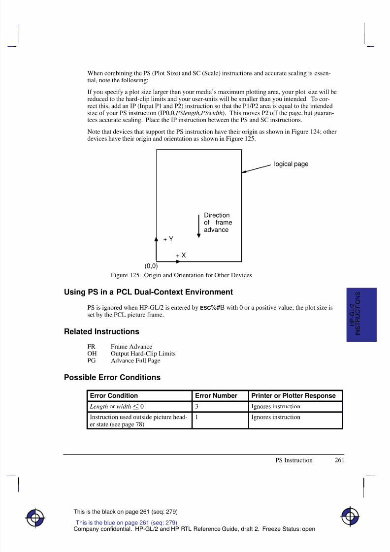
8/12/2019 HPGL2-RTL ReferenceGuide 5961-3526 540pages Sep96
http://slidepdf.com/reader/full/hpgl2-rtl-referenceguide-5961-3526-540pages-sep96 279/539
261
This is the black on page 261 (seq: 279)
Company confidential. HP-GL/2 and HP RTL Reference Guide, draft 2. Freeze Status: open
When combining the PS (Plot Size) and SC (Scale) instructions and accurate scaling is essen-tial, note the following:
If you specify a plot size larger than your media’s maximum plotting area, your plot size will bereduced to the hard-clip limits and your user-units will be smaller than you intended. To cor-rect this, add an IP (Input P1 and P2) instruction so that the P1/P2 area is equal to the intendedsize of your PS instruction (IP0,0,PSlength,PSwidth). This moves P2 off the page, but guaran-tees accurate scaling. Place the IP instruction between the PS and SC instructions.
Note that devices that support the PS instruction have their origin as shown in Figure 124; otherdevices have their origin and orientation as shown in Figure 125.
(0,0)
+ Y
+ X
Directionof frameadvance
logical page
Figure 125. Origin and Orientation for Other Devices
Using PS in a PCL Dual-Context Environment
PS is ignored when HP-GL/2 is entered by %#B with 0 or a positive value; the plot size isset by the PCL picture frame.
Related Instructions
FR Frame AdvanceOH Output Hard-Clip LimitsPG Advance Full Page
Possible Error Conditions
Error Condition Error Number Printer or Plotter Response
Length or width 0 3 Ignores instruction
Instruction used outside picture head-er state (see page 78)
1 Ignores instruction
This is the blue on page 261 (seq: 279)
I N S T R U C T I O N S
H P - G L / 2
PS Instruction
8/12/2019 HPGL2-RTL ReferenceGuide 5961-3526 540pages Sep96
http://slidepdf.com/reader/full/hpgl2-rtl-referenceguide-5961-3526-540pages-sep96 280/539
262
This is the black on page 262 (seq: 280)
Company confidential. HP-GL/2 and HP RTL Reference Guide, draft 2. Freeze Status: open
PU, Pen Up
Purpose
To move to subsequent points without drawing. Use PU to move to another location withoutdrawing a connecting line.
Syntax
PU X,Y[,...;]or
PU [;]
Á Á Á Á Á Á Á
Á Á Á Á Á Á Á
ParameterÁ Á Á Á Á Á
Á Á Á Á Á Á
FormatÁ Á Á Á Á Á Á Á
Á Á Á Á Á Á Á Á
Functional RangeÁ Á Á Á Á Á Á Á
Á Á Á Á Á Á Á Á
Parameter DefaultÁ Á Á Á Á Á Á
Á Á Á Á Á Á Á
Á Á Á Á Á Á Á
X,Y coordinates orincrements
Á Á Á Á Á Á
Á Á Á Á Á Á
Á Á Á Á Á Á
current units
Á Á Á Á Á Á Á Á
Á Á Á Á Á Á Á Á
Á Á Á Á Á Á Á Á
device-dependent (at least –223 to 223 – 1)
Á Á Á Á Á Á Á Á
Á Á Á Á Á Á Á Á
Á Á Á Á Á Á Á Á
no default
Group
This instruction is in the Vector Group.
Use
The PU instruction emulates a pen plotter which must raise the pen to prevent drawing straylines on the page.
No Parameters: Prevents drawing subsequent graphics instructions (unless the instruction
contains an automatic pen down).
X,Y coordinates or increments: Move to the point(s) specified. You can specify as manyX,Y coordinate pairs as you want. When you include more than one coordinate pair, thedevice moves to each point in the order given.
The carriage-return point (see page 66) is moved to the last X,Y.
When you use the SM (Symbol Mode) instruction, PU draws the specified symbol at each X,Ycoordinate.
When you use the PM (Polygon Mode) instruction, the X,Y coordinates enter the polygon buff-er (for use when the polygon is edged or filled).
Coordinates are interpreted in current units: as user-units when scaling is on; as plotter-unitswhen scaling is off. Whether the PU instruction uses absolute coordinates or relative coordi-
nates (increments) depends on the most recently executed PA or PR instruction. If you have notissued a PA or PR instruction, absolute plotting (PA) is used.
Note that “PD;PU;” leaves a dot.
This is the blue on page 262 (seq: 280)
PU Instruction
8/12/2019 HPGL2-RTL ReferenceGuide 5961-3526 540pages Sep96
http://slidepdf.com/reader/full/hpgl2-rtl-referenceguide-5961-3526-540pages-sep96 281/539
263
This is the black on page 263 (seq: 281)
Company confidential. HP-GL/2 and HP RTL Reference Guide, draft 2. Freeze Status: open
Related Instructions
PA Plot Absolute
PD Pen DownPE Polyline EncodedPR Plot RelativeSM Symbol Mode
Possible Error Conditions
Error Condition Error Number Printer or Plotter Response
An odd number of coordinates (an Xcoordinate without a correspondingY coordinate)
2 Ignores the last unmatched coor-dinate.
This is the blue on page 263 (seq: 281)
PU Instruction
I N S T R U C T I O N S
H P - G L / 2
8/12/2019 HPGL2-RTL ReferenceGuide 5961-3526 540pages Sep96
http://slidepdf.com/reader/full/hpgl2-rtl-referenceguide-5961-3526-540pages-sep96 282/539
264
This is the black on page 264 (seq: 282)
Company confidential. HP-GL/2 and HP RTL Reference Guide, draft 2. Freeze Status: open
PW, Pen Width
Purpose
To specify a new width for the logical pen. Subsequent lines are drawn in this new width. UsePW to vary your lines and enhance your drawings. Pen width can be specified as a fixed valueor relative to the distance between P1 and P2. The pen width units are selected using the WUinstruction (the default is metric—millimeters).
Syntax
PW width[,pen][;]or
PW [;]
Á Á Á Á Á Á Á
Á Á Á Á Á Á Á
ParameterÁ Á Á Á Á Á
Á Á Á Á Á Á
FormatÁ Á Á Á Á Á Á Á
Á Á Á Á Á Á Á Á
Functional RangeÁ Á Á Á Á Á Á Á
Á Á Á Á Á Á Á Á
Parameter DefaultÁ Á Á Á Á Á Á
Á Á Á Á Á Á Á
Á Á Á Á Á Á Á
width
Á Á Á Á Á Á
Á
Á Á Á Á Á
Á Á Á Á Á Á
clamped real
Á Á Á Á Á Á Á Á
Á
Á Á Á Á Á Á Á
Á Á Á Á Á Á Á Á
device-dependent*
Á Á Á Á Á Á Á Á
Á
Á Á Á Á Á Á Á
Á Á Á Á Á Á Á Á
dependent**
Á Á Á Á Á Á Á
Á Á Á Á Á Á Á
pen Á Á Á Á Á Á
Á Á Á Á Á Á
integer Á Á Á Á Á Á Á Á
Á Á Á Á Á Á Á Á
device-dependent Á Á Á Á Á Á Á Á
Á Á Á Á Á Á Á Á
all pens
* Normally 0 to 32 767, but at least 16 384 plotter-units (409.6 mm).
** Dependent on the mode set by the WU (Pen Width Unit Selection) instruction: if mode ismetric, default width is 0.35 mm; if mode is relative, default width is 0.1% of the diagonaldistance from P1 to P2.
Group
This instruction is in the Line and Fill Attributes Group.
Use
You may change the pen width as often as you like, without sending another SP instruction. If the pen is down when you change the width, the new width takes effect at the next line. If youuse WU to change the type of units used for the width parameter (metric or relative), send theWU instruction before PW.
No Parameters: Defaults the pen line width according to the current units set by WU:0.35 mm if metric; 0.1% of the diagonal distance from P1 to P2 if relative.
width: Specifies the line width. When the parameter is zero or is thinner than the thinnestsupported width, the device assumes the thinnest line width (1 dot wide). When it is
greater than the device’s maximum, the maximum is used.
pen: Specifies the pen number to which the new width applies. If the pen parameter is notspecified, the device applies the width to both pens. Specifying pen numbers less than 0 orgreater than the number of pens available causes the device to ignore the instruction.
Note: Pen width does not set the width of lines for drawing labels (unless the stroke weightvalue is set to 9999 [Stick/Arc fonts only]). The width of character lines is determined by thestroke weight attribute of the AD (Alternate Font Definition) or SD (Standard Font Definition)instructions.
This is the blue on page 264 (seq: 282)
PW Instruction
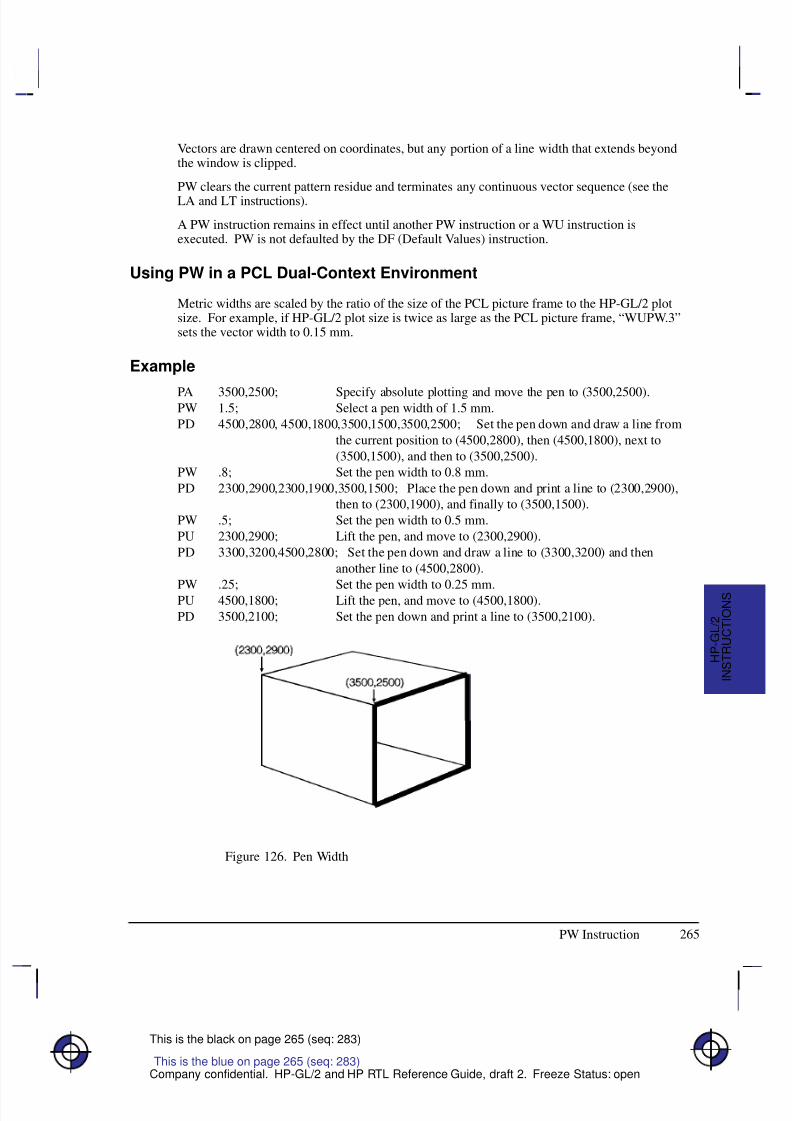
8/12/2019 HPGL2-RTL ReferenceGuide 5961-3526 540pages Sep96
http://slidepdf.com/reader/full/hpgl2-rtl-referenceguide-5961-3526-540pages-sep96 283/539
265
This is the black on page 265 (seq: 283)
Company confidential. HP-GL/2 and HP RTL Reference Guide, draft 2. Freeze Status: open
Vectors are drawn centered on coordinates, but any portion of a line width that extends beyondthe window is clipped.
PW clears the current pattern residue and terminates any continuous vector sequence (see theLA and LT instructions).
A PW instruction remains in effect until another PW instruction or a WU instruction isexecuted. PW is not defaulted by the DF (Default Values) instruction.
Using PW in a PCL Dual-Context Environment
Metric widths are scaled by the ratio of the size of the PCL picture frame to the HP-GL/2 plotsize. For example, if HP-GL/2 plot size is twice as large as the PCL picture frame, “WUPW.3”sets the vector width to 0.15 mm.
Example
PA 3500,2500; Specify absolute plotting and move the pen to (3500,2500).PW 1.5; Select a pen width of 1.5 mm.
PD 4500,2800, 4500,1800,3500,1500,3500,2500; Set the pen down and draw a line from
the current position to (4500,2800), then (4500,1800), next to
(3500,1500), and then to (3500,2500).
PW .8; Set the pen width to 0.8 mm.
PD 2300,2900,2300,1900,3500,1500; Place the pen down and print a line to (2300,2900),
then to (2300,1900), and finally to (3500,1500).
PW .5; Set the pen width to 0.5 mm.
PU 2300,2900; Lift the pen, and move to (2300,2900).
PD 3300,3200,4500,2800; Set the pen down and draw a line to (3300,3200) and then
another line to (4500,2800).
PW .25; Set the pen width to 0.25 mm.PU 4500,1800; Lift the pen, and move to (4500,1800).
PD 3500,2100; Set the pen down and print a line to (3500,2100).
Figure 126. Pen Width
This is the blue on page 265 (seq: 283)
I N S T R U C T I O N S
H P - G L / 2
PW Instruction

8/12/2019 HPGL2-RTL ReferenceGuide 5961-3526 540pages Sep96
http://slidepdf.com/reader/full/hpgl2-rtl-referenceguide-5961-3526-540pages-sep96 284/539
266
This is the black on page 266 (seq: 284)
Company confidential. HP-GL/2 and HP RTL Reference Guide, draft 2. Freeze Status: open
Related Instructions
SP Select Pen
SV Screened VectorsWU Pen Width Unit Selection
PW Instruction
8/12/2019 HPGL2-RTL ReferenceGuide 5961-3526 540pages Sep96
http://slidepdf.com/reader/full/hpgl2-rtl-referenceguide-5961-3526-540pages-sep96 285/539
267
This is the black on page 267 (seq: 285)
Company confidential. HP-GL/2 and HP RTL Reference Guide, draft 2. Freeze Status: open
QL, Quality Level
Purpose
To set “best”, “normal” or “draft” mode for your output. Use QL on raster devices to optimizeyour usage of toner or ink when draft quality is sufficient.
Syntax
QL quality_level [;]or
QL [;]
Á Á Á Á Á Á Á
Á Á Á Á Á Á Á
ParameterÁ Á Á Á Á Á Á
Á Á Á Á Á Á Á
FormatÁ Á Á Á Á Á Á Á
Á Á Á Á Á Á Á Á
Functional RangeÁ Á Á Á Á Á Á
Á Á Á Á Á Á Á
Parameter DefaultÁ Á Á Á Á Á Á
Á Á Á Á Á Á Á
quality_level
Á Á Á Á Á Á Á
Á Á Á Á Á Á Á
clamped integer
Á Á Á Á Á Á Á Á
Á Á Á Á Á Á Á Á
0 to 100
Á Á Á Á Á Á Á
Á Á Á Á Á Á Á
device-dependent
Group
This instruction is in the Technical Graphics Extension.
Use
The entire plot must be done with one quality level setting. You cannot change quality levels inthe picture body state.
No Parameter: Device-dependent. Each device makes different use of this instructiondepending on the hardware technology and firmware implementation. The result will be
seen in different speed/quality trade-offs. For example, a pen plotter primarily varies penspeed, but may vary acceleration as well. An electrostatic plotter might vary paper speed,resolution, or rasterization algorithms. Refer to the manual for your product or HP-GL/2option for the number of quality levels and the effects the various levels have on theoutput.
quality_level: Specifies the level of quality for your plot from 0 (draft quality) to 100(presentation, best, or final quality). The number of quality levels supported is device-de-pendent. When quality level is 0 (draft), a plotter may not implement MC (Merge Control)or may limit it to vectors only.
A device with only one quality level will ignore this instruction. A device with two or morelevels will support at least 0 and 100 and will map any other value to one of the supported val-ues. Mapping to another value may occur either through rounding to the nearest supportedvalue (for example, a device with only two levels would treat “QL60;” the same as “QL100;”),
or through applying a threshold (for example, anything over 80 is mapped to 100).
For a pen plotter, QL is primarily a speed control. The pen speed set by the VS (Velocity Se-lect) instruction or from the device’s control panel is the maximum speed, which corresponds to“QL0;”. If the pen speed is not set by VS or from the control panel, the plotter determines themaximum speed based on its knowledge of the media type (from the MT instruction) and pentype (from the carousel). Minimum speed, corresponding to “QL100;”, is linearly interpolatedbetween the media and pen types. The default level for pen plotters is usually “QL0;” (maxi-mum speed).
This is the blue on page 267 (seq: 285)
QL Instruction
I N S T R U C T I O N S
H P - G L / 2

8/12/2019 HPGL2-RTL ReferenceGuide 5961-3526 540pages Sep96
http://slidepdf.com/reader/full/hpgl2-rtl-referenceguide-5961-3526-540pages-sep96 286/539
268
This is the black on page 268 (seq: 286)
Company confidential. HP-GL/2 and HP RTL Reference Guide, draft 2. Freeze Status: open
Possible Error Conditions
Error Condition Error Number Printer or Plotter Response
Instruction used outside picture head-er state (see page 78)
1 Ignores instruction
QL Instruction
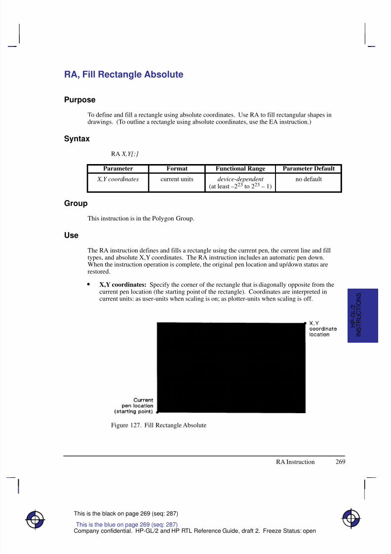
8/12/2019 HPGL2-RTL ReferenceGuide 5961-3526 540pages Sep96
http://slidepdf.com/reader/full/hpgl2-rtl-referenceguide-5961-3526-540pages-sep96 287/539
8/12/2019 HPGL2-RTL ReferenceGuide 5961-3526 540pages Sep96
http://slidepdf.com/reader/full/hpgl2-rtl-referenceguide-5961-3526-540pages-sep96 288/539
270
This is the black on page 270 (seq: 288)
Company confidential. HP-GL/2 and HP RTL Reference Guide, draft 2. Freeze Status: open
Note: Figure 127 shows the current pen location in the lower-left corner and the instruction’sX,Y coordinates in the upper-right corner. Depending on the X,Y coordinates used, thesepoints can be in any two diagonally opposite corners.
The only difference between the RA instruction and the EA (Edge Rectangle Absolute) instruc-tion is that the RA instruction produces a filled rectangle, and EA, an outlined one.
The RA instruction clears the polygon buffer and then uses it to define the rectangle beforedrawing. Refer to Using the Polygon Buffer on page 45.
A dot is drawn if X,Y are coincident with the current position. A line is drawn if the X or Ycoordinate equals the corresponding coordinate of the current position; for some hatch or raster-filled patterns, the line may fall in white spaces of the fill and not be drawn.
Related Instructions
EA Edge Rectangle AbsoluteEP Edge PolygonER Edge Rectangle RelativeFP Fill PolygonFT Fill TypeLT Line TypeRF Raster Fill DefinitionRR Fill Rectangle Relative
Example
The following example uses RA with three different fill types to create rectangles such as thoseyou might use in a bar chart. The rectangles in the right bar are edged using the EA instruction.(For more information about fill types, refer to the FT instruction description on page 183.)
PA 400,400; Enter absolute plotting mode and move to (400,400).
RA 800,1200; Draw a rectangle with (400,400) as the lower left corner and
(800,1200) as the upper right corner.
PA 400,1200; Move the pen to (400,1200).
FT 3,50; Select fill type 3 (parallel lines) with a 50 plotter-units space be-
tween lines.
RA 800,1600; Draw a rectangle with (400,1200) as the lower left corner and
(800,1600) as the upper right corner.
PA 400,1600; Move to (400,1600).
FT 4; Specify fill type 4 (cross-hatching).
RA 800,2000; Draw a rectangle with a lower left corner of (400,1600) and an
upper right corner of (800,2000).
PA 1200,400; Move to location (1200,400).
FT ; Select the default fill type (solid black).RA 1600,1200; Fill and edge a rectangle using (1200,400) as the lower left corner
EA 1600,1200; and (1600,1200) as the upper right corner.
PA 1200,1200; Move to absolute position (1200,1200).
FT 3,50; Select fill type 3, with a 50 plotter-units distance between each
line.
RA 1600,1600; Draw a rectangle with (1200,1200) as the lower left corner and
(1600,1600) as the upper right.
RA Instruction
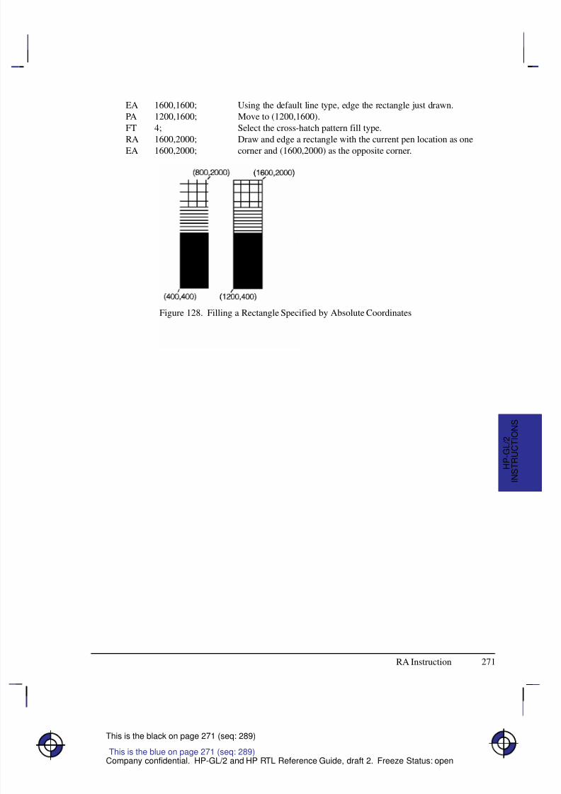
8/12/2019 HPGL2-RTL ReferenceGuide 5961-3526 540pages Sep96
http://slidepdf.com/reader/full/hpgl2-rtl-referenceguide-5961-3526-540pages-sep96 289/539
271
This is the black on page 271 (seq: 289)
Company confidential. HP-GL/2 and HP RTL Reference Guide, draft 2. Freeze Status: open
EA 1600,1600; Using the default line type, edge the rectangle just drawn.
PA 1200,1600; Move to (1200,1600).
FT 4; Select the cross-hatch pattern fill type.
RA 1600,2000; Draw and edge a rectangle with the current pen location as oneEA 1600,2000; corner and (1600,2000) as the opposite corner.
Figure 128. Filling a Rectangle Specified by Absolute Coordinates
This is the blue on page 271 (seq: 289)
RA Instruction
I N S T R U C T I O N S
H P - G L / 2
8/12/2019 HPGL2-RTL ReferenceGuide 5961-3526 540pages Sep96
http://slidepdf.com/reader/full/hpgl2-rtl-referenceguide-5961-3526-540pages-sep96 290/539
272
This is the black on page 272 (seq: 290)
Company confidential. HP-GL/2 and HP RTL Reference Guide, draft 2. Freeze Status: open
RF, Raster Fill Definition
Purpose
To define a rectangular pattern that may be used as area fill and for screened vectors (see theSV instruction). Use RF to create your own fill types and screen patterns.
Syntax
RF index,width,height,pen_number[,...pen_number][;]or
RF index[;]or
RF [;]
Á Á Á Á Á Á Á
Á Á Á Á Á Á Á
ParameterÁ Á Á Á Á Á
Á Á Á Á Á Á
FormatÁ Á Á Á Á Á Á Á
Á Á Á Á Á Á Á Á
Functional RangeÁ Á Á Á Á Á Á Á
Á Á Á Á Á Á Á Á
Parameter DefaultÁ Á Á Á Á Á Á
Á Á Á Á Á Á Á
Á Á Á Á Á Á Á
index
Á Á Á Á Á Á
Á
Á Á Á Á Á
Á Á Á Á Á Á
clamped integer
Á Á Á Á Á Á Á Á
Á
Á Á Á Á Á Á Á
Á Á Á Á Á Á Á Á
device-dependent
Á Á Á Á Á Á Á Á
Á
Á Á Á Á Á Á Á
Á Á Á Á Á Á Á Á
1 (solid)
Á Á Á Á Á Á Á
Á Á Á Á Á Á Á
width Á Á Á Á Á Á
Á Á Á Á Á Á
clamped integerÁ Á Á Á Á Á Á Á
Á Á Á Á Á Á Á Á
device-dependent * Á Á Á Á Á Á Á Á
Á Á Á Á Á Á Á Á
no default
Á Á Á Á Á Á Á
Á Á Á Á Á Á Á
height Á Á Á Á Á Á
Á Á Á Á Á Á
clamped integerÁ Á Á Á Á Á Á Á
Á Á Á Á Á Á Á Á
device-dependent *Á Á Á Á Á Á Á Á
Á Á Á Á Á Á Á Á
no defaultÁ Á Á Á Á Á Á
Á Á Á Á Á Á Á
Á Á Á Á Á Á Á
pen_number Á Á Á Á Á Á
Á
Á Á Á Á Á
Á Á Á Á Á Á
integerÁ Á Á Á Á Á Á Á
Á
Á Á Á Á Á Á Á
Á Á Á Á Á Á Á Á
device-dependent **Á Á Á Á Á Á Á Á
Á
Á Á Á Á Á Á Á
Á Á Á Á Á Á Á Á
no default
* The range is between 1 and a positive power of 2; at least the values 8, 16, 32, and 64are supported.
** See the NP (Number of Pens) instruction on page 225.
Group
This instruction is in the Line and Fill Attributes Group.
Use
The RF instruction does not select a fill type; use the FT (Fill Type) instruction with a type pa-rameter of 11 and the corresponding raster fill index number for the second parameter (forexample, “FT11,3” for an index number of 3).
No Parameters: Defaults all raster fill patterns to solid fill.
index: Specifies the index number of the pattern being defined. At least eight patterns can
exist concurrently.When you send RF with an index parameter only (“RFn”), the corresponding pattern isdefaulted to solid fill.
width, height: Specify the width and height (in pixels) of the pattern being defined. Apixel is equal to the size of one dot at the current device resolution.
pen_number: Represents a pixel in the pattern being defined and indicates its color.
This is the blue on page 272 (seq: 290)
RF Instruction
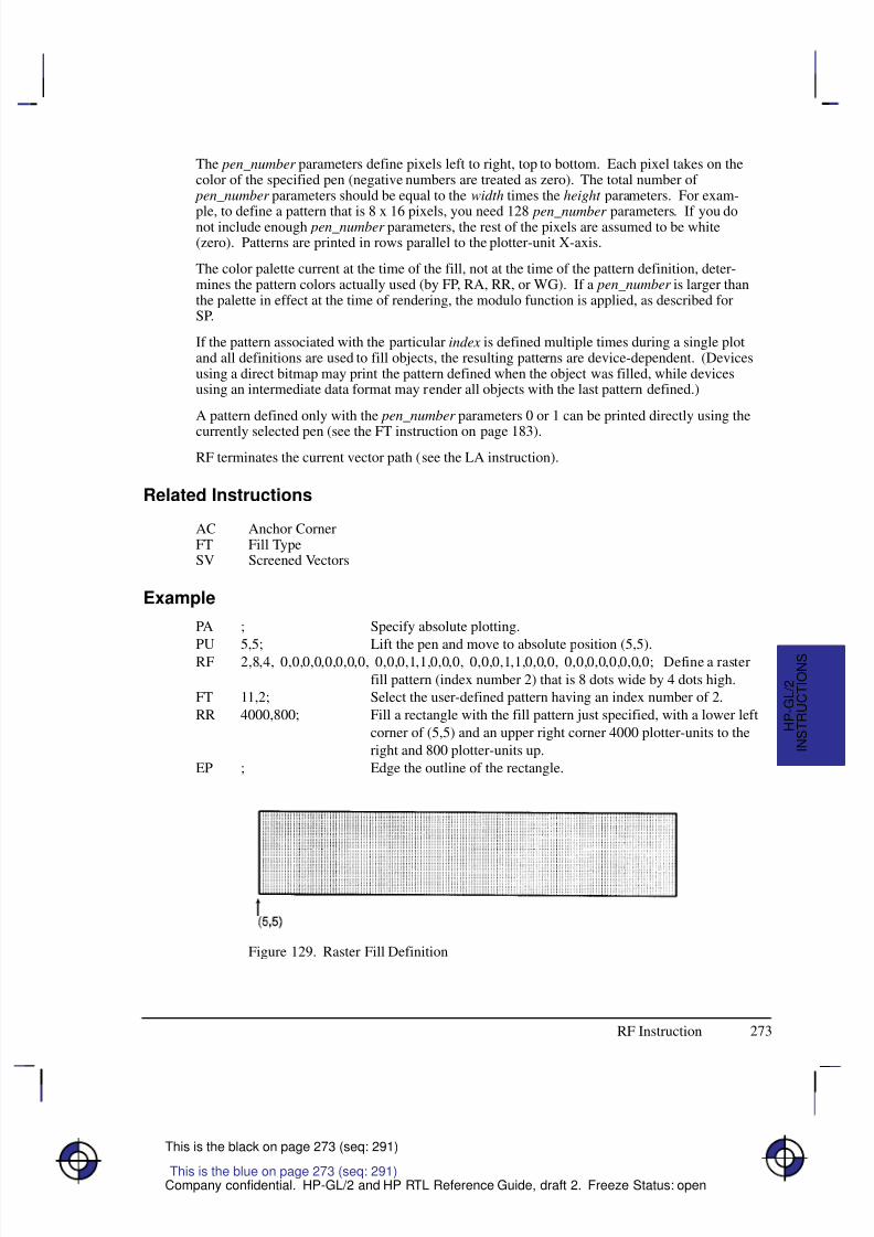
8/12/2019 HPGL2-RTL ReferenceGuide 5961-3526 540pages Sep96
http://slidepdf.com/reader/full/hpgl2-rtl-referenceguide-5961-3526-540pages-sep96 291/539
273
This is the black on page 273 (seq: 291)
Company confidential. HP-GL/2 and HP RTL Reference Guide, draft 2. Freeze Status: open
The pen_number parameters define pixels left to right, top to bottom. Each pixel takes on thecolor of the specified pen (negative numbers are treated as zero). The total number of
pen_number parameters should be equal to the width times the height parameters. For exam-
ple, to define a pattern that is 8 x 16 pixels, you need 128 pen_number parameters. If you donot include enough pen_number parameters, the rest of the pixels are assumed to be white(zero). Patterns are printed in rows parallel to the plotter-unit X-axis.
The color palette current at the time of the fill, not at the time of the pattern definition, deter-mines the pattern colors actually used (by FP, RA, RR, or WG). If a pen_number is larger thanthe palette in effect at the time of rendering, the modulo function is applied, as described forSP.
If the pattern associated with the particular index is defined multiple times during a single plotand all definitions are used to fill objects, the resulting patterns are device-dependent. (Devicesusing a direct bitmap may print the pattern defined when the object was filled, while devicesusing an intermediate data format may render all objects with the last pattern defined.)
A pattern defined only with the pen_number parameters 0 or 1 can be printed directly using the
currently selected pen (see the FT instruction on page 183).
RF terminates the current vector path (see the LA instruction).
Related Instructions
AC Anchor CornerFT Fill TypeSV Screened Vectors
Example
PA ; Specify absolute plotting.
PU 5,5; Lift the pen and move to absolute position (5,5).RF 2,8,4, 0,0,0,0,0,0,0,0, 0,0,0,1,1,0,0,0, 0,0,0,1,1,0,0,0, 0,0,0,0,0,0,0,0; Define a raster
fill pattern (index number 2) that is 8 dots wide by 4 dots high.
FT 11,2; Select the user-defined pattern having an index number of 2.
RR 4000,800; Fill a rectangle with the fill pattern just specified, with a lower left
corner of (5,5) and an upper right corner 4000 plotter-units to the
right and 800 plotter-units up.
EP ; Edge the outline of the rectangle.
Figure 129. Raster Fill Definition
This is the blue on page 273 (seq: 291)
I N S T R U C T I O N S
H P - G L / 2
RF Instruction

8/12/2019 HPGL2-RTL ReferenceGuide 5961-3526 540pages Sep96
http://slidepdf.com/reader/full/hpgl2-rtl-referenceguide-5961-3526-540pages-sep96 292/539
274
This is the black on page 274 (seq: 292)
Company confidential. HP-GL/2 and HP RTL Reference Guide, draft 2. Freeze Status: open
Possible Error Conditions
Error Condition Error Number Printer or Plotter Response
Index out of range 3 Ignores instruction
RF Instruction
8/12/2019 HPGL2-RTL ReferenceGuide 5961-3526 540pages Sep96
http://slidepdf.com/reader/full/hpgl2-rtl-referenceguide-5961-3526-540pages-sep96 293/539
275
This is the black on page 275 (seq: 293)
Company confidential. HP-GL/2 and HP RTL Reference Guide, draft 2. Freeze Status: open
RO, Rotate Coordinate System
Purpose
To rotate the device’s coordinate system relative to the default HP-GL/2 coordinate system, inthe following increments of rotation: 90, 180, and 270. Use RO to orient your drawing ver-tically or horizontally, or to reverse the orientation.
Syntax
RO angle[;]or
RO [;]
Á Á Á Á Á Á Á
Á Á Á Á Á Á Á
Parameter Á Á Á Á Á Á Á
Á Á Á Á Á Á Á
Format Á Á Á Á Á Á Á Á
Á Á Á Á Á Á Á Á
Functional Range Á Á Á Á Á Á Á
Á Á Á Á Á Á Á
Parameter Default
Á Á Á Á Á Á Á
Á Á Á Á Á Á Á
angle Á Á Á Á Á Á Á
Á Á Á Á Á Á Á
clamped integer Á Á Á Á Á Á Á Á
Á Á Á Á Á Á Á Á
0, 90, 180, or 270 Á Á Á Á Á Á Á
Á Á Á Á Á Á Á
0
Group
This instruction is in the Configuration and Status Group.
Use
The device interprets the instruction parameters as follows:
No Parameter: Defaults the orientation of the coordinate system to 0. Equivalent to“RO0”. This is the same as PCL’s current orientation in PCL devices; for other devices,
see the description of the PS (Plot Size) instruction on page 259.
angle: Specifies the degree of rotation:
0 Sets the orientation to horizontal (+X direction).
90 Rotates and shifts the coordinate system 90 in a positive angle of rotation fromthe horizontal (+X direction).
180 Rotates and shifts the coordinate system 180 in a positive angle of rotation fromthe horizontal (+X direction).
270 Rotates and shifts the coordinate system 270 in a positive angle of rotation fromthe horizontal (+X direction).
The carriage-return point is updated to the current pen location.
A positive angle of rotation is in the direction of the +X-axis to the +Y-axis as shown in Figure27 on page 44). (A negative angle of rotation is not allowed in the RO instruction.)
The relationship of the X-axis to Y-axis can change as a result of the scaling point or scalingfactor changes, thus changing the direction of a positive angle of rotation.
The physical location of the pen does not change when you rotate the coordinate system. Thedevice updates the pen’s X,Y coordinate location to reflect the new orientation.
This is the blue on page 275 (seq: 293)
RO Instruction
I N S T R U C T I O N S
H P - G L / 2
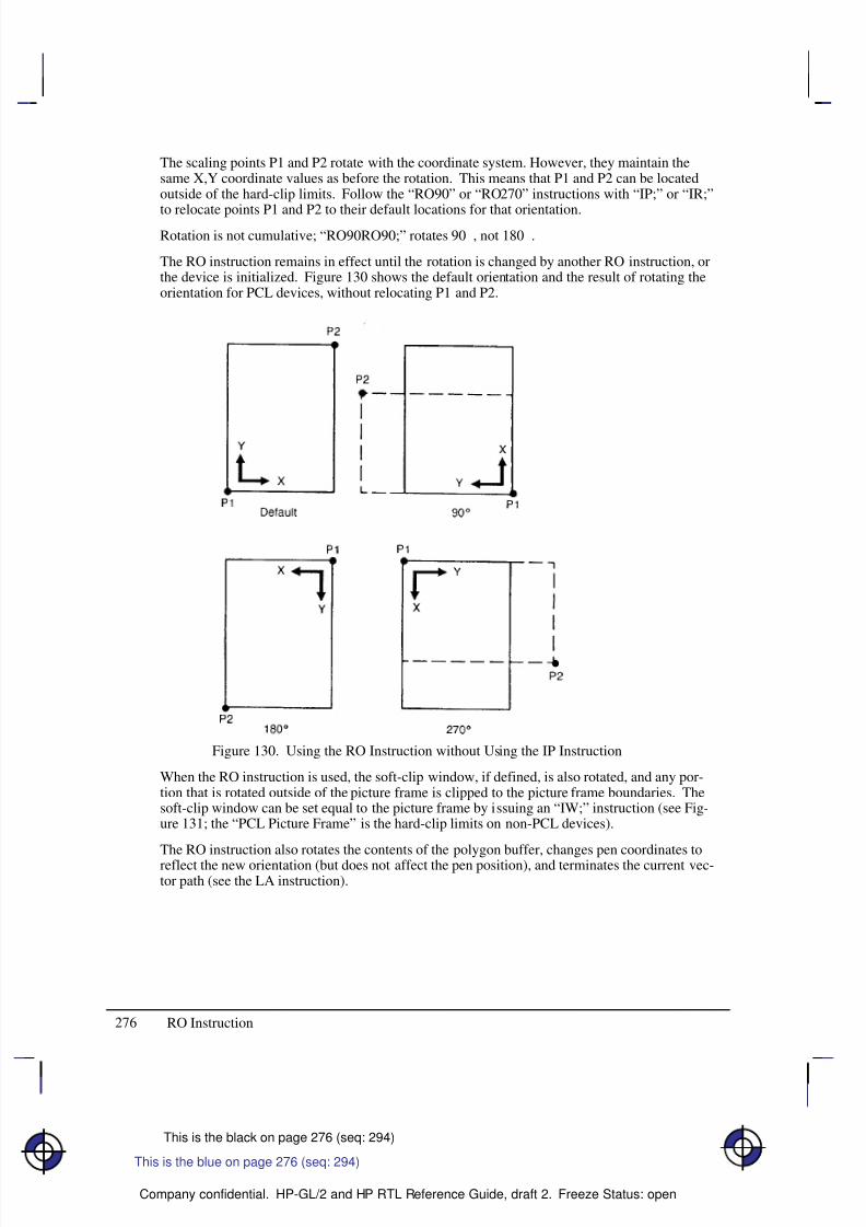
8/12/2019 HPGL2-RTL ReferenceGuide 5961-3526 540pages Sep96
http://slidepdf.com/reader/full/hpgl2-rtl-referenceguide-5961-3526-540pages-sep96 294/539
276
This is the black on page 276 (seq: 294)
Company confidential. HP-GL/2 and HP RTL Reference Guide, draft 2. Freeze Status: open
The scaling points P1 and P2 rotate with the coordinate system. However, they maintain thesame X,Y coordinate values as before the rotation. This means that P1 and P2 can be locatedoutside of the hard-clip limits. Follow the “RO90” or “RO270” instructions with “IP;” or “IR;”
to relocate points P1 and P2 to their default locations for that orientation.Rotation is not cumulative; “RO90RO90;” rotates 90, not 180.
The RO instruction remains in effect until the rotation is changed by another RO instruction, orthe device is initialized. Figure 130 shows the default orientation and the result of rotating theorientation for PCL devices, without relocating P1 and P2.
Figure 130. Using the RO Instruction without Using the IP Instruction
When the RO instruction is used, the soft-clip window, if defined, is also rotated, and any por-tion that is rotated outside of the picture frame is clipped to the picture frame boundaries. Thesoft-clip window can be set equal to the picture frame by issuing an “IW;” instruction (see Fig-ure 131; the “PCL Picture Frame” is the hard-clip limits on non-PCL devices).
The RO instruction also rotates the contents of the polygon buffer, changes pen coordinates toreflect the new orientation (but does not affect the pen position), and terminates the current vec-tor path (see the LA instruction).
RO Instruction
This is the blue on page 276 (seq: 294)
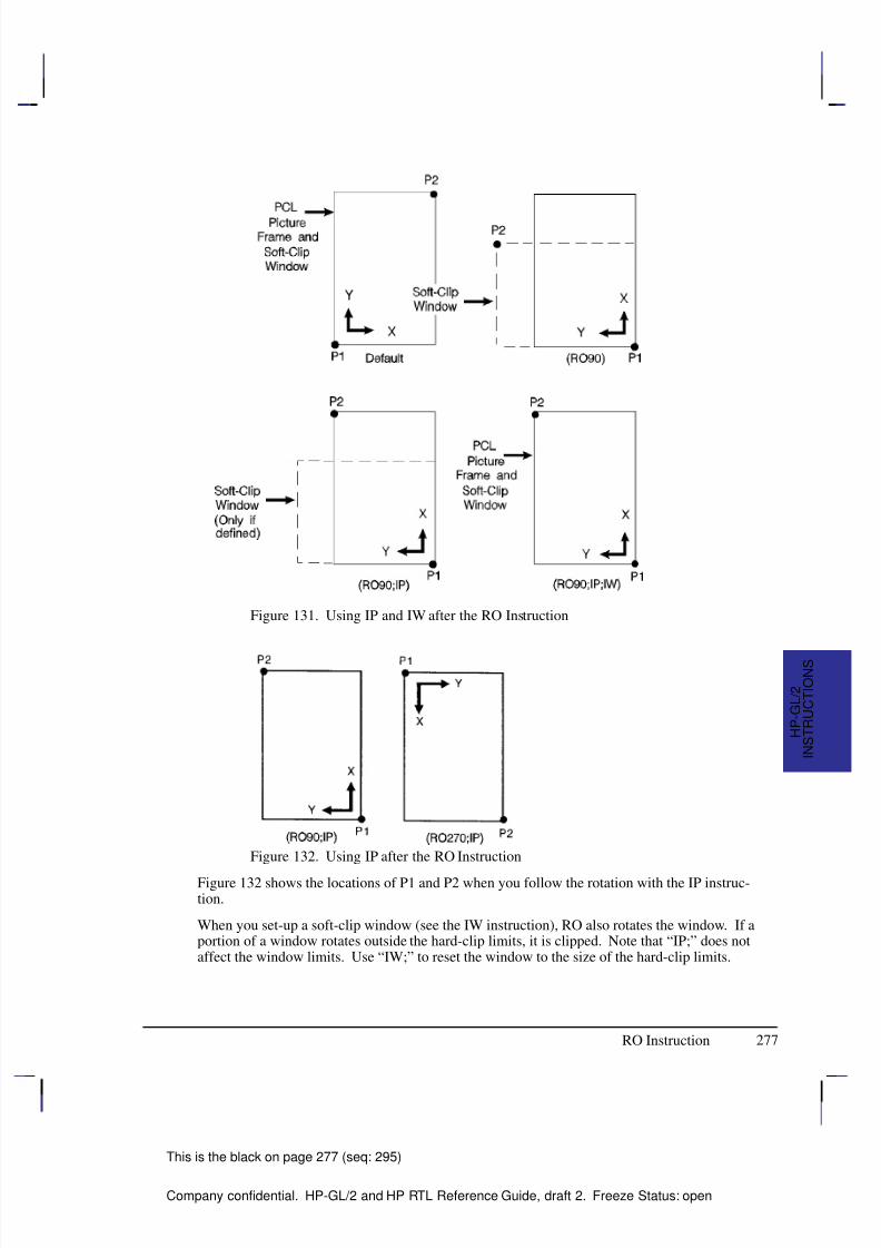
8/12/2019 HPGL2-RTL ReferenceGuide 5961-3526 540pages Sep96
http://slidepdf.com/reader/full/hpgl2-rtl-referenceguide-5961-3526-540pages-sep96 295/539

8/12/2019 HPGL2-RTL ReferenceGuide 5961-3526 540pages Sep96
http://slidepdf.com/reader/full/hpgl2-rtl-referenceguide-5961-3526-540pages-sep96 296/539
278
This is the black on page 278 (seq: 296)
Company confidential. HP-GL/2 and HP RTL Reference Guide, draft 2. Freeze Status: open
Using RO in a PCL Dual-Context Environment
Rotations are relative to the default HP-GL/2 coordinate system, as defined for PCL. P1 or P2
may be rotated outside the current picture frame; they can be repositioned to the rotated lower-left and upper-right corners of the picture frame by issuing an “IP;” or an “IR;” instruction.The user-defined window is rotated, and any portion that is rotated outside the picture frame isclipped to the picture frame. The window can be set equal to the picture frame by an “IW;”instruction.
Related Instructions
IP Input P1 and P2IR Input Relative P1 and P2IW Input Window
RO Instruction
8/12/2019 HPGL2-RTL ReferenceGuide 5961-3526 540pages Sep96
http://slidepdf.com/reader/full/hpgl2-rtl-referenceguide-5961-3526-540pages-sep96 297/539
279
This is the black on page 279 (seq: 297)
Company confidential. HP-GL/2 and HP RTL Reference Guide, draft 2. Freeze Status: open
RP, Replot
Purpose
To draw multiple copies of plots. Your device must have an internal hard disk or designatedbuffer area to store the plot. This instruction is ignored on devices that cannot store the plotdata.
Syntax
RP n;or
RP ;
This instruction, with or without a parameter, must be terminated by a semicolon.
Á Á Á Á Á Á Á
Á Á Á Á Á Á Á
Parameter Á Á Á Á Á Á Á
Á Á Á Á Á Á Á
Format Á Á Á Á Á Á Á Á
Á Á Á Á Á Á Á Á
Functional Range Á Á Á Á Á Á Á
Á Á Á Á Á Á Á
Parameter DefaultÁ Á Á Á Á Á Á
Á Á Á Á Á Á Á
nÁ Á Á Á Á Á Á
Á Á Á Á Á Á Á
clamped integerÁ Á Á Á Á Á Á Á
Á Á Á Á Á Á Á Á
–32 768 to 32 767Á Á Á Á Á Á Á
Á Á Á Á Á Á Á
1
Group
This instruction is in the Configuration and Status Group.
Use
Use the RP instruction at the end of your plot, following the PG (Advance Full Page) instruc-tion when you want more than one copy of a plot.
No Parameter: Assumes you want one additional copy.
n: Specifies the number of additional copies required.
The device ignores the instruction when printing the current page would produce no marks onthe media.
RP prints the page when the plot has not already been terminated by a PG instruction. If n isless than or equal to zero and there is no previous PG instruction, the device prints the page (itissues a “PG;” instruction) and otherwise ignores the instruction. If n is greater than the maxi-mum value allowed for the device, the value is clamped to the maximum value.
RP clears the current pattern residue and terminates any continuous vector sequence (see theLA and LT instructions).
Using RP in a PCL Dual-Context Environment
This instruction is ignored in PCL; a page eject can only be accomplished from the PCL con-text by sending a form feed () control character. To print more than one plot, use the NC(Number of Copies) instruction described on page 225.
This is the blue on page 279 (seq: 297)
RP Instruction
I N S T R U C T I O N S
H P - G L / 2

8/12/2019 HPGL2-RTL ReferenceGuide 5961-3526 540pages Sep96
http://slidepdf.com/reader/full/hpgl2-rtl-referenceguide-5961-3526-540pages-sep96 298/539
280
This is the black on page 280 (seq: 298)
Company confidential. HP-GL/2 and HP RTL Reference Guide, draft 2. Freeze Status: open
Related Instructions
BP Begin Plot
NC Number of CopiesPG Advance Full Page
RP Instruction
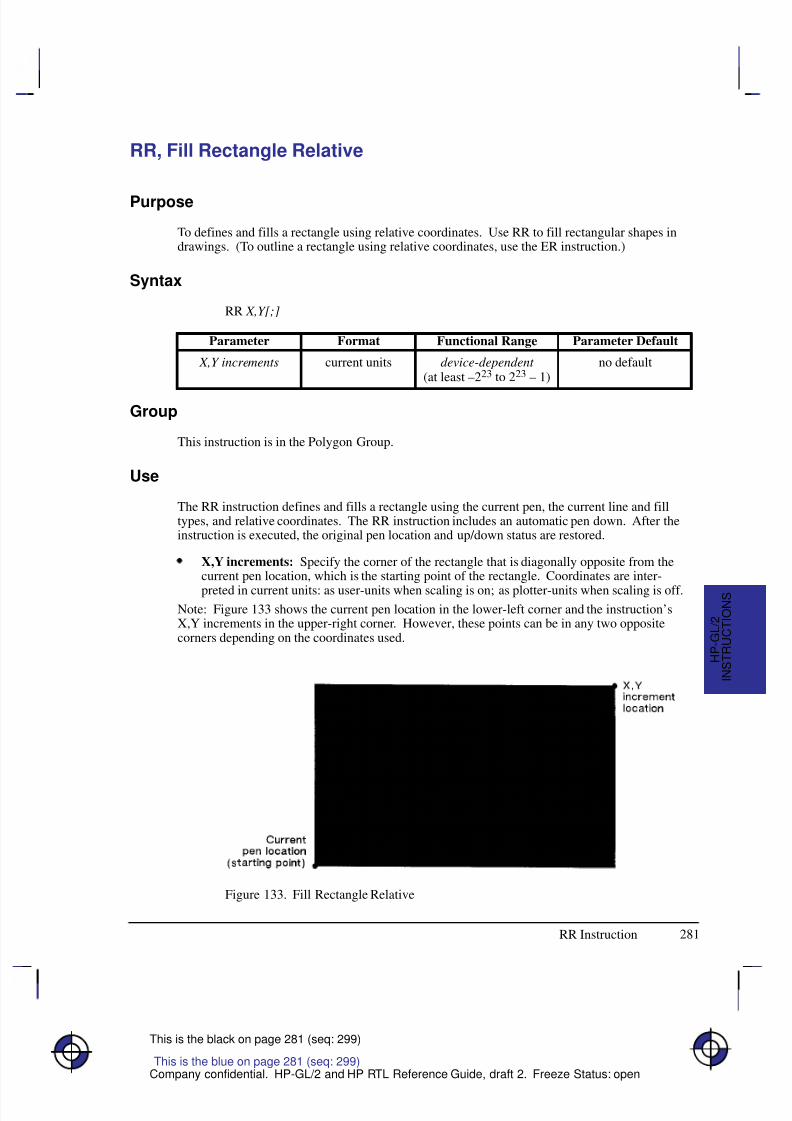
8/12/2019 HPGL2-RTL ReferenceGuide 5961-3526 540pages Sep96
http://slidepdf.com/reader/full/hpgl2-rtl-referenceguide-5961-3526-540pages-sep96 299/539
281
This is the black on page 281 (seq: 299)
Company confidential. HP-GL/2 and HP RTL Reference Guide, draft 2. Freeze Status: open
RR, Fill Rectangle Relative
Purpose
To defines and fills a rectangle using relative coordinates. Use RR to fill rectangular shapes indrawings. (To outline a rectangle using relative coordinates, use the ER instruction.)
Syntax
RR X,Y[;]
Á Á Á Á Á Á Á
Á Á Á Á Á Á Á
ParameterÁ Á Á Á Á Á Á
Á Á Á Á Á Á Á
FormatÁ Á Á Á Á Á Á Á
Á Á Á Á Á Á Á Á
Functional RangeÁ Á Á Á Á Á Á
Á Á Á Á Á Á Á
Parameter Default
Á Á Á Á Á Á Á
Á
Á Á Á Á Á Á
Á Á Á Á Á Á Á
X,Y increments Á Á Á Á Á Á Á
Á
Á Á Á Á Á Á
Á Á Á Á Á Á Á
current units Á Á Á Á Á Á Á Á
Á
Á Á Á Á Á Á Á
Á Á Á Á Á Á Á Á
device-dependent (at least –223 to 223 – 1)
Á Á Á Á Á Á Á
Á
Á Á Á Á Á Á
Á Á Á Á Á Á Á
no default
Group
This instruction is in the Polygon Group.
Use
The RR instruction defines and fills a rectangle using the current pen, the current line and filltypes, and relative coordinates. The RR instruction includes an automatic pen down. After theinstruction is executed, the original pen location and up/down status are restored.
X,Y increments: Specify the corner of the rectangle that is diagonally opposite from thecurrent pen location, which is the starting point of the rectangle. Coordinates are inter-
preted in current units: as user-units when scaling is on; as plotter-units when scaling is off.Note: Figure 133 shows the current pen location in the lower-left corner and the instruction’sX,Y increments in the upper-right corner. However, these points can be in any two oppositecorners depending on the coordinates used.
Figure 133. Fill Rectangle Relative
This is the blue on page 281 (seq: 299)
RR Instruction
I N S T R U C T I O N S
H P - G L / 2
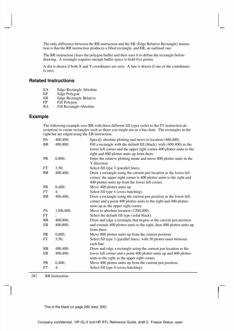
8/12/2019 HPGL2-RTL ReferenceGuide 5961-3526 540pages Sep96
http://slidepdf.com/reader/full/hpgl2-rtl-referenceguide-5961-3526-540pages-sep96 300/539
282
This is the black on page 282 (seq: 300)
Company confidential. HP-GL/2 and HP RTL Reference Guide, draft 2. Freeze Status: open
The only difference between the RR instruction and the ER (Edge Relative Rectangle) instruc-tion is that the RR instruction produces a filled rectangle, and ER, an outlined one.
The RR instruction clears the polygon buffer and then uses it to define the rectangle beforedrawing. A rectangle requires enough buffer space to hold five points.
A dot is drawn if both X and Y coordinates are zero. A line is drawn if one of the coordinatesis zero.
Related Instructions
EA Edge Rectangle AbsoluteEP Edge PolygonER Edge Rectangle RelativeFP Fill PolygonRA Fill Rectangle Absolute
Example
The following example uses RR with three different fill types (refer to the FT instruction de-scription) to create rectangles such as those you might use in a bar chart. The rectangles in theright bar are edged using the ER instruction.
PA 400,400; Specify absolute plotting and move to location (400,400).
RR 400,800; Fill a rectangle with the default fill (black), with (400,400) as the
lower left corner and the upper right corner 400 plotter-units to the
right and 800 plotter-units up from there.
PR 0,800; Enter the relative plotting mode and move 800 plotter-units in the
Y direction.
FT 3,50; Select fill type 3 (parallel lines).
RR 400,400; Draw a rectangle using the current pen location as the lower leftcorner; the upper right corner is 400 plotter-units to the right and
400 plotter-units up from the lower left corner.
PR 0,400; Move 400 plotter-units up.
FT 4; Select fill type 4 (cross-hatching).
RR 400,400; Draw a rectangle using the current pen position as the lower left
corner and a point 400 plotter-units to the right and 400 plotter-
units up as the upper right corner.
PA 1200,400; Move to absolute location (1200,400).
FT ; Select the default fill type (solid black).
RR 400,800; Draw and edge a rectangle that begins at the current pen position
ER 400,800; and extends 400 plotter-units to the right, then 800 plotter-units up
from there.
PR 0,800; Move 800 plotter-units up from the current position.
FT 3,50; Select fill type 3 (parallel lines), with 50 plotter-units between
each line.
RR 400,400; Draw and edge a rectangle using the current pen location as the
ER 400,400; lower left corner and a point 400 plotter-units up and 400 plotter-
units to the right as the upper right corner.
PR 0,400; Move 400 plotter-units up from the current pen position.
FT 4; Select fill type 4 (cross-hatching).
RR Instruction
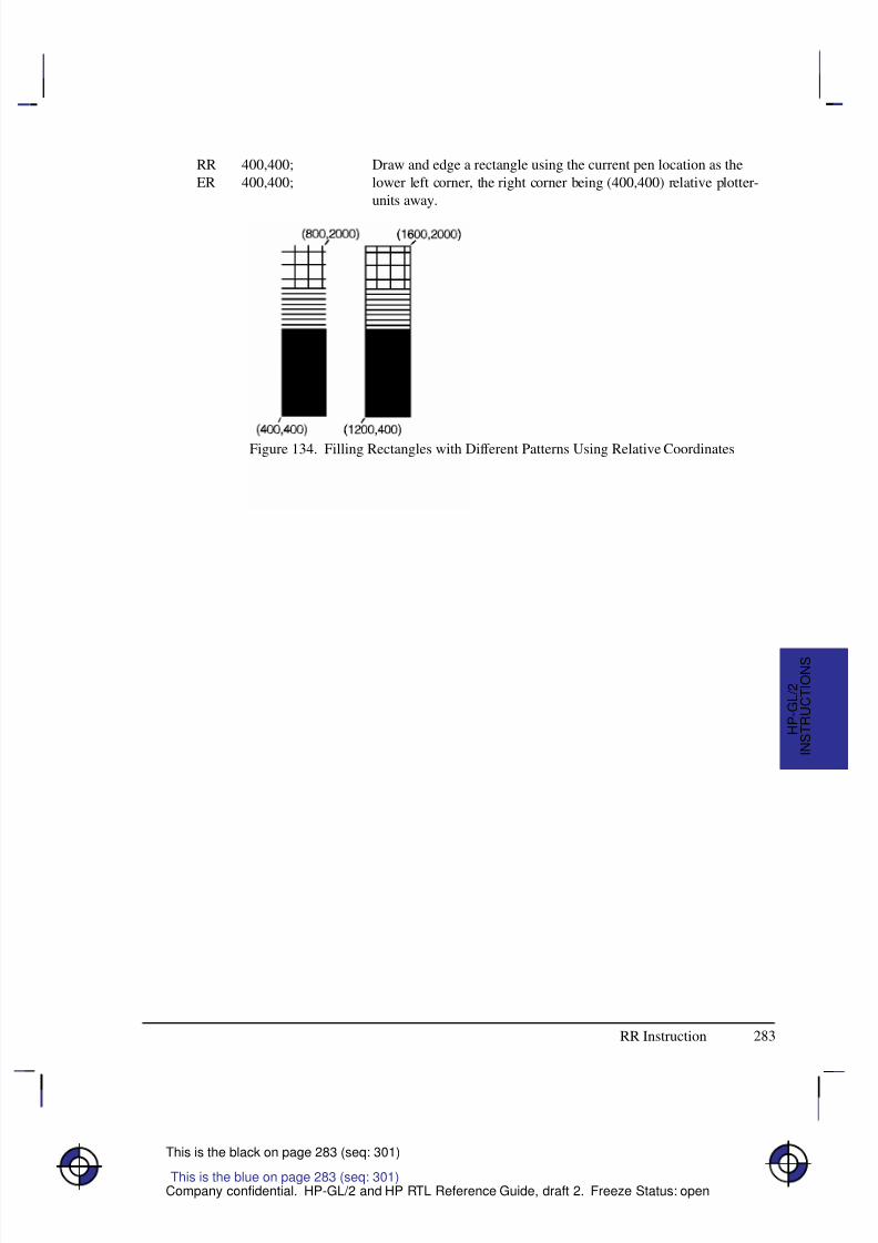
8/12/2019 HPGL2-RTL ReferenceGuide 5961-3526 540pages Sep96
http://slidepdf.com/reader/full/hpgl2-rtl-referenceguide-5961-3526-540pages-sep96 301/539
283
This is the black on page 283 (seq: 301)
Company confidential. HP-GL/2 and HP RTL Reference Guide, draft 2. Freeze Status: open
RR 400,400; Draw and edge a rectangle using the current pen location as the
ER 400,400; lower left corner, the right corner being (400,400) relative plotter-
units away.
Figure 134. Filling Rectangles with Different Patterns Using Relative Coordinates
This is the blue on page 283 (seq: 301)
RR Instruction
I N S T R U C T I O N S
H P - G L / 2
8/12/2019 HPGL2-RTL ReferenceGuide 5961-3526 540pages Sep96
http://slidepdf.com/reader/full/hpgl2-rtl-referenceguide-5961-3526-540pages-sep96 302/539
284
This is the black on page 284 (seq: 302)
Company confidential. HP-GL/2 and HP RTL Reference Guide, draft 2. Freeze Status: open
RT, Relative Arc Three Point
Purpose
To draw an arc segment, using relative coordinates, from a starting point through an intermedi-ate point to an end point. Use RT when you know these three points of an arc.
Syntax
RT X incr_inter ,Y incr_inter , X incr_end ,Y incr_end [,chord_angle][;]
Á Á Á Á Á Á Á
Á Á Á Á Á Á Á
ParameterÁ Á Á Á Á Á
Á Á Á Á Á Á
FormatÁ Á Á Á Á Á Á Á
Á Á Á Á Á Á Á Á
Functional RangeÁ Á Á Á Á Á Á Á
Á Á Á Á Á Á Á Á
Parameter Default
Á Á Á Á Á Á Á
Á Á Á Á Á Á Á
Á Á Á Á Á Á Á
X, Y increments(intermediate and
end points)
Á Á Á Á Á Á
Á
Á Á Á Á Á
Á Á Á Á Á Á
current units Á Á Á Á Á Á Á Á
Á
Á Á Á Á Á Á Á
Á Á Á Á Á Á Á Á
device-dependent (at least –223 to 223 – 1)
Á Á Á Á Á Á Á Á
Á
Á Á Á Á Á Á Á
Á Á Á Á Á Á Á Á
no defaults
Á Á Á Á Á Á Á
Á Á Á Á Á Á Á
Á Á Á Á Á Á Á
chord_angle*
Á Á Á Á Á Á
Á
Á Á Á Á Á
Á Á Á Á Á Á
clamped realÁ Á Á Á Á Á Á Á
Á
Á Á Á Á Á Á Á
Á Á Á Á Á Á Á Á
0 to 360Á Á Á Á Á Á Á Á
Á
Á Á Á Á Á Á Á
Á Á Á Á Á Á Á Á
device-dependent (usually 5
* If you have used the “CT1” instruction, the chord_angle is interpreted as a deviation dis-tance in current units; see the CT instruction on page 133.
Group
This instruction is in the Vector Group.
Use
The RT instruction uses the current pen location and two specified points to calculate a circleand draw the appropriate arc segment of its circumference. The arc starts at the current penlocation, using the current pen, line type, line attributes and pen up/down status. You specifythe intermediate and end points. After drawing the arc, the pen location remains at the end of the arc; the carriage-return point (see page 66) is moved to the end of the arc.
Xincr_inter,Yincr_inter: Specify the location of an intermediate point of the arc in relativeincrements (relative to the current pen location). The arc is drawn in a negative or positivedirection, as necessary, so that it passes through the intermediate point before the end point.
Xincr_end,Yincr_end: Specify the location of the end point of the arc in relative increments(relative to the current pen location).
chord_angle: Specifies the chord angle used to draw the arc. The default is a chord angle
of 5. (The Arc Absolute instruction description on page 100 contains more informationon chords and chord angles.)
Intermediate and end point coordinates are interpreted in current units: as user-units when scal-ing is on; as plotter-units when scaling is off. If current scaling is not isotropic, the arc drawn iselliptical rather than circular. Note the following about intermediate and end points:
If the intermediate point and end point are the same as the current pen location, the instruc-tion draws a dot.
This is the blue on page 284 (seq: 302)
RT Instruction
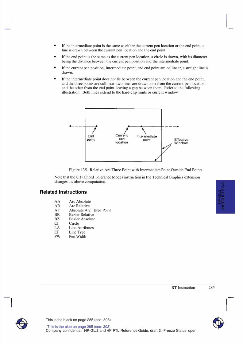
8/12/2019 HPGL2-RTL ReferenceGuide 5961-3526 540pages Sep96
http://slidepdf.com/reader/full/hpgl2-rtl-referenceguide-5961-3526-540pages-sep96 303/539
285
This is the black on page 285 (seq: 303)
Company confidential. HP-GL/2 and HP RTL Reference Guide, draft 2. Freeze Status: open
If the intermediate point is the same as either the current pen location or the end point, aline is drawn between the current pen location and the end point.
If the end point is the same as the current pen location, a circle is drawn, with its diameter
being the distance between the current pen position and the intermediate point.
If the current pen position, intermediate point, and end point are collinear, a straight line isdrawn.
If the intermediate point does not lie between the current pen location and the end point,and the three points are collinear, two lines are drawn, one from the current pen locationand the other from the end point, leaving a gap between them. Refer to the followingillustration. Both lines extend to the hard-clip limits or current window.
Figure 135. Relative Arc Three Point with Intermediate Point Outside End Points
Note that the CT (Chord Tolerance Mode) instruction in the Technical Graphics extension
changes the above computation.
Related Instructions
AA Arc AbsoluteAR Arc RelativeAT Absolute Arc Three PointBR Bezier RelativeBZ Bezier AbsoluteCI CircleLA Line AttributesLT Line TypePW Pen Width
This is the blue on page 285 (seq: 303)
RT Instruction
I N S T R U C T I O N S
H P - G L / 2
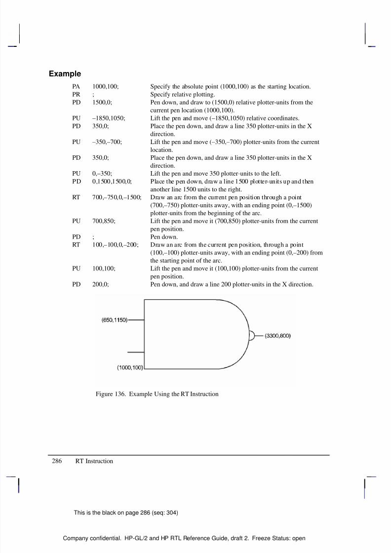
8/12/2019 HPGL2-RTL ReferenceGuide 5961-3526 540pages Sep96
http://slidepdf.com/reader/full/hpgl2-rtl-referenceguide-5961-3526-540pages-sep96 304/539
286
This is the black on page 286 (seq: 304)
Company confidential. HP-GL/2 and HP RTL Reference Guide, draft 2. Freeze Status: open
Example
PA 1000,100; Specify the absolute point (1000,100) as the starting location.
PR ; Specify relative plotting.PD 1500,0; Pen down, and draw to (1500,0) relative plotter-units from the
current pen location (1000,100).
PU –1850,1050; Lift the pen and move (–1850,1050) relative coordinates.
PD 350,0; Place the pen down, and draw a line 350 plotter-units in the X
direction.
PU –350,–700; Lift the pen and move (–350,–700) plotter-units from the current
location.
PD 350,0; Place the pen down, and draw a line 350 plotter-units in the X
direction.
PU 0,–350; Lift the pen and move 350 plotter-units to the left.
PD 0,1500,1500,0; Place the pen down, draw a line 1500 plotter-units up and then
another line 1500 units to the right.
RT 700,–750,0,–1500; Draw an arc from the current pen position through a point
(700,–750) plotter-units away, with an ending point (0,–1500)
plotter-units from the beginning of the arc.
PU 700,850; Lift the pen and move it (700,850) plotter-units from the current
pen position.
PD ; Pen down.
RT 100,–100,0,–200; Draw an arc from the current pen position, through a point
(100,–100) plotter-units away, with an ending point (0,–200) from
the starting point of the arc.
PU 100,100; Lift the pen and move it (100,100) plotter-units from the current
pen position.
PD 200,0; Pen down, and draw a line 200 plotter-units in the X direction.
Figure 136. Example Using the RT Instruction
RT Instruction
8/12/2019 HPGL2-RTL ReferenceGuide 5961-3526 540pages Sep96
http://slidepdf.com/reader/full/hpgl2-rtl-referenceguide-5961-3526-540pages-sep96 305/539
287
This is the black on page 287 (seq: 305)
Company confidential. HP-GL/2 and HP RTL Reference Guide, draft 2. Freeze Status: open
SA, Select Alternate Font
Purpose
To select the alternate font (already designated by the AD instruction) for subsequent labeling.Use the SA instruction to shift from the currently selected standard font to the designated alter-nate font.
Syntax
SA [;]
Group
This instruction is in the Character Group.
Use
The SA instruction tells the device to draw subsequent labeling instructions using charactersfrom the alternate symbol set previously designated by the AD instruction. The SA instructionis equivalent to using the Shift Out control character (, decimal 14) within a label string.
The default designated alternate font uses symbol set 277 (Roman-8). The alternate font re-mains in effect until an SS instruction is executed, a Shift In control character (, decimal 15)is encountered, or the device is initialized or set to default conditions.
Related Instructions
AD Alternate Font DefinitionDT Define Label TerminatorFI Select Primary FontFN Select Secondary FontLB LabelSD Standard Font DefinitionSS Select Standard Font
This is the blue on page 287 (seq: 305)
SA Instruction
I N S T R U C T I O N S
H P - G L / 2
8/12/2019 HPGL2-RTL ReferenceGuide 5961-3526 540pages Sep96
http://slidepdf.com/reader/full/hpgl2-rtl-referenceguide-5961-3526-540pages-sep96 306/539
288
This is the black on page 288 (seq: 306)
Company confidential. HP-GL/2 and HP RTL Reference Guide, draft 2. Freeze Status: open
SB, Scalable or Bitmap Fonts
Purpose
To specify the type of font to be used in subsequent labeling. It allows you to restrict fontselection to only scalable fonts and the stick and arc fonts, disregarding bitmap fonts.
Syntax
SB n[;]or
SB [;]
Á Á Á Á Á Á Á
Á Á Á Á Á Á Á
ParameterÁ Á Á Á Á Á Á
Á Á Á Á Á Á Á
FormatÁ Á Á Á Á Á Á Á
Á Á Á Á Á Á Á Á
Functional RangeÁ Á Á Á Á Á Á
Á Á Á Á Á Á Á
Parameter Default
Á Á Á Á Á Á Á
nÁ Á Á Á Á Á Á
clamped integerÁ Á Á Á Á Á Á Á
0 or 1Á Á Á Á Á Á Á
0
Group
This instruction is in the Dual-Context and Advanced Text Extensions.
Use
This instruction is defaulted by the DF (Default Values) and IN (Initialize) instructions. The SBinstruction takes effect immediately, changing both the standard (primary) and alternate (sec-ondary) fonts to be scalable only or bitmap allowed , as requested.
No Parameter: Defaults to scalable fonts. Equivalent to “SB0”.
n: Determines the type of font according to the following parameter values:
0 Scalable fonts only.
1 Bitmap fonts are allowed. All fonts will be subject to the same restrictions as bit-map fonts; that is, there is limited character fill, no slant, limited direction andsize, and character-clipped rather than bit-clipped.
SB1 (bitmap) changes the meanings of the following HP-GL/2 kernel instructions,and can affect their performance:
Á Á Á Á
Á Á Á Á
CFÁ Á Á Á Á Á Á Á Á Á Á Á Á Á Á Á Á Á Á Á
Á Á Á Á Á Á Á Á Á Á Á Á Á Á Á Á Á Á Á Á
Bitmap characters cannot be edged.Á Á Á Á
Á Á Á Á
Á
Á Á Á
Á Á Á Á
DI, DRÁ Á Á Á Á Á Á Á Á Á Á Á Á Á Á Á Á Á Á Á
Á Á Á Á Á Á Á Á Á Á Á Á Á Á Á Á Á Á Á Á
Á
Á Á Á Á Á Á Á Á Á Á Á Á Á Á Á Á Á Á Á
Á Á Á Á Á Á Á Á Á Á Á Á Á Á Á Á Á Á Á Á
Bitmap characters can be printed only with orthogonal orientations(0, 90, 180, or 270). Refer to the DI instruction for an illustra-tion of direction instructions with bitmap fonts.
Á Á Á Á
Á Á Á ÁSI, SR
Á Á Á Á Á Á Á Á Á Á Á Á Á Á Á Á Á Á Á Á
Á Á Á Á Á Á Á Á Á Á Á Á Á Á Á Á Á Á Á ÁSizes for bitmap fonts are approximate only.Á Á Á Á
Á Á Á Á
SLÁ Á Á Á Á Á Á Á Á Á Á Á Á Á Á Á Á Á Á Á
Á Á Á Á Á Á Á Á Á Á Á Á Á Á Á Á Á Á Á Á
Slant is ignored for bitmap fonts.
Scalable fonts respond more accurately to some HP-GL/2 instructions. The choice of scalableor bitmap fonts can affect the performance of the following HP-GL/2 instructions: AD, SD, CP,LB.
Note: The FI and FN instructions implicitly change the value of SB. For example, if SB = 0and FI selects a bitmap font, SB is set to 1.
This is the blue on page 288 (seq: 306)
SB Instruction
8/12/2019 HPGL2-RTL ReferenceGuide 5961-3526 540pages Sep96
http://slidepdf.com/reader/full/hpgl2-rtl-referenceguide-5961-3526-540pages-sep96 307/539
289
This is the black on page 289 (seq: 307)
Company confidential. HP-GL/2 and HP RTL Reference Guide, draft 2. Freeze Status: open
SB is ignored in devices that do not support both scalable and bitmap fonts.
Scalable fonts are computationally more complex than bitmap fonts, but they respond moreaccurately to some HP-GL/2 instructions. Bitmap fonts may offer a wider range of typefaceson some devices for plots that do not use the size, direction, slant, or character fill instructions.
SB takes place immediately, changing both the standard and alternate fonts to scalable or bit-map, as requested.
The DF and IN instructions default SB to 0.
Related Instructions
CF Character Fill ModeDI Absolute DirectionDR Relative DirectionSI Absolute Character SizeSL Character SlantSR Relative Character Size
This is the blue on page 289 (seq: 307)
SB Instruction
I N S T R U C T I O N S
H P - G L / 2
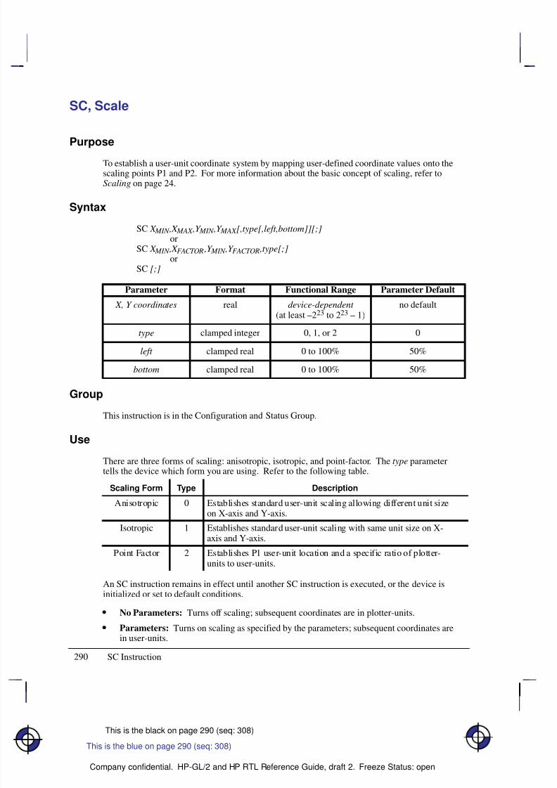
8/12/2019 HPGL2-RTL ReferenceGuide 5961-3526 540pages Sep96
http://slidepdf.com/reader/full/hpgl2-rtl-referenceguide-5961-3526-540pages-sep96 308/539
290
This is the black on page 290 (seq: 308)
Company confidential. HP-GL/2 and HP RTL Reference Guide, draft 2. Freeze Status: open
SC, Scale
Purpose
To establish a user-unit coordinate system by mapping user-defined coordinate values onto thescaling points P1 and P2. For more information about the basic concept of scaling, refer toScaling on page 24.
Syntax
SC X MIN ,X MAX ,Y MIN ,Y MAX [,type[,left,bottom]][;]or
SC X MIN ,X FACTOR ,Y MIN ,Y FACTOR ,type[;]or
SC [;]
Á Á Á Á Á Á Á
Á Á Á Á Á Á Á
ParameterÁ Á Á Á Á Á
Á Á Á Á Á Á
FormatÁ Á Á Á Á Á Á Á
Á Á Á Á Á Á Á Á
Functional RangeÁ Á Á Á Á Á Á Á
Á Á Á Á Á Á Á Á
Parameter DefaultÁ Á Á Á Á Á Á
Á Á Á Á Á Á Á
Á Á Á Á Á Á Á
X, Y coordinatesÁ Á Á Á Á Á
Á Á Á Á Á Á
Á Á Á Á Á Á
realÁ Á Á Á Á Á Á Á
Á Á Á Á Á Á Á Á
Á Á Á Á Á Á Á Á
device-dependent (at least –223 to 223 – 1)
Á Á Á Á Á Á Á Á
Á Á Á Á Á Á Á Á
Á Á Á Á Á Á Á Á
no default
Á Á Á Á Á Á Á
Á Á Á Á Á Á Á
Á Á Á Á Á Á Á
typeÁ Á Á Á Á Á
Á Á Á Á Á Á
Á Á Á Á Á Á
clamped integerÁ Á Á Á Á Á Á Á
Á Á Á Á Á Á Á Á
Á Á Á Á Á Á Á Á
0, 1, or 2Á Á Á Á Á Á Á Á
Á Á Á Á Á Á Á Á
Á Á Á Á Á Á Á Á
0Á Á Á Á Á Á Á
Á Á Á Á Á Á Á
Á Á Á Á Á Á Á
left
Á Á Á Á Á Á
Á
Á Á Á Á Á
Á Á Á Á Á Á
clamped real
Á Á Á Á Á Á Á Á
Á
Á Á Á Á Á Á Á
Á Á Á Á Á Á Á Á
0 to 100%
Á Á Á Á Á Á Á Á
Á
Á Á Á Á Á Á Á
Á Á Á Á Á Á Á Á
50%
Á Á Á Á Á Á Á
Á Á Á Á Á Á Á
bottom Á Á Á Á Á Á
Á Á Á Á Á Á
clamped real Á Á Á Á Á Á Á Á
Á Á Á Á Á Á Á Á
0 to 100% Á Á Á Á Á Á Á Á
Á Á Á Á Á Á Á Á
50%
Group
This instruction is in the Configuration and Status Group.
Use
There are three forms of scaling: anisotropic, isotropic, and point-factor. The type parametertells the device which form you are using. Refer to the following table.
Scaling Form Type Description
Anisotropic 0 Establishes standard user-unit scaling allowing different unit sizeon X-axis and Y-axis.
Isotropic 1 Establishes standard user-unit scaling with same unit size on X-axis and Y-axis.
Point Factor 2 Establishes P1 user-unit location and a specific ratio of plotter-units to user-units.
An SC instruction remains in effect until another SC instruction is executed, or the device isinitialized or set to default conditions.
No Parameters: Turns off scaling; subsequent coordinates are in plotter-units.
Parameters: Turns on scaling as specified by the parameters; subsequent coordinates arein user-units.
This is the blue on page 290 (seq: 308)
SC Instruction
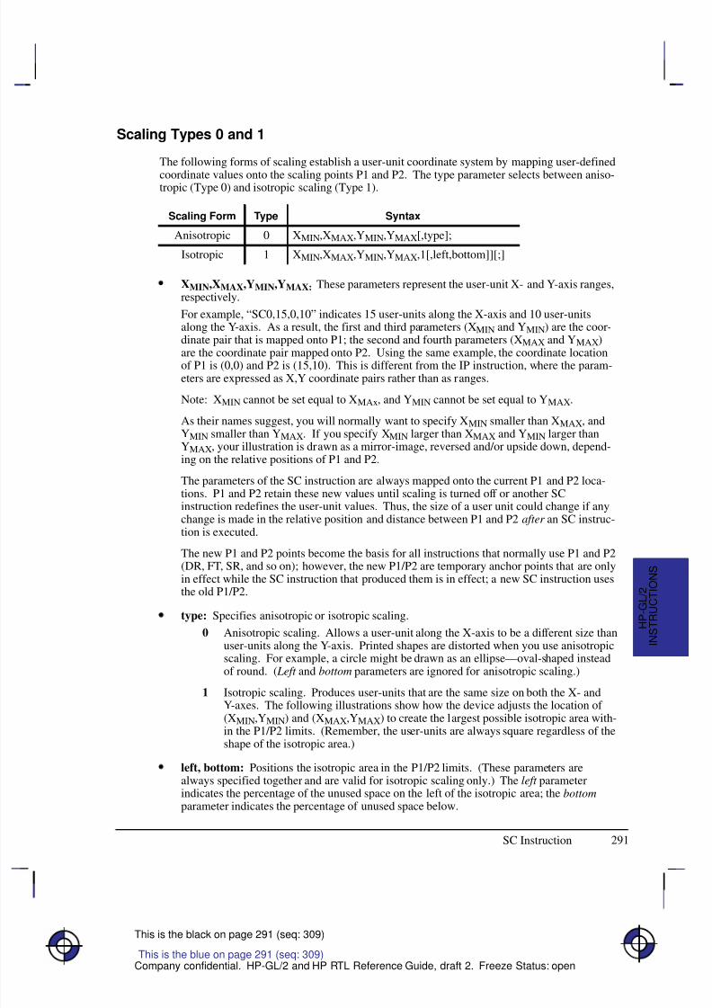
8/12/2019 HPGL2-RTL ReferenceGuide 5961-3526 540pages Sep96
http://slidepdf.com/reader/full/hpgl2-rtl-referenceguide-5961-3526-540pages-sep96 309/539
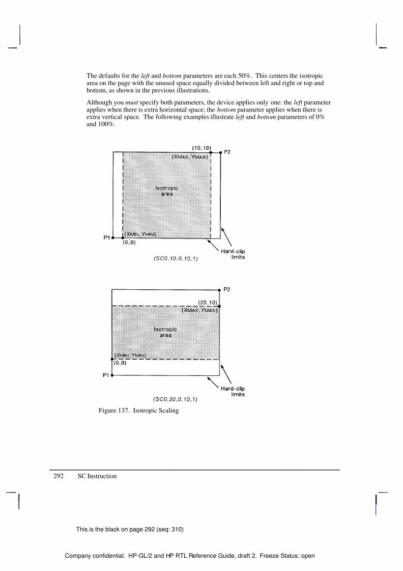
8/12/2019 HPGL2-RTL ReferenceGuide 5961-3526 540pages Sep96
http://slidepdf.com/reader/full/hpgl2-rtl-referenceguide-5961-3526-540pages-sep96 310/539
292
This is the black on page 292 (seq: 310)
Company confidential. HP-GL/2 and HP RTL Reference Guide, draft 2. Freeze Status: open
The defaults for the left and bottom parameters are each 50%. This centers the isotropicarea on the page with the unused space equally divided between left and right or top andbottom, as shown in the previous illustrations.
Although you must specify both parameters, the device applies only one: the left parameterapplies when there is extra horizontal space; the bottom parameter applies when there isextra vertical space. The following examples illustrate left and bottom parameters of 0%and 100%.
Figure 137. Isotropic Scaling
SC Instruction
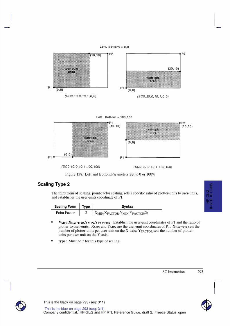
8/12/2019 HPGL2-RTL ReferenceGuide 5961-3526 540pages Sep96
http://slidepdf.com/reader/full/hpgl2-rtl-referenceguide-5961-3526-540pages-sep96 311/539
293
This is the black on page 293 (seq: 311)
Company confidential. HP-GL/2 and HP RTL Reference Guide, draft 2. Freeze Status: open
Figure 138. Left and Bottom Parameters Set to 0 or 100%
Scaling Type 2
The third form of scaling, point-factor scaling, sets a specific ratio of plotter-units to user-units,and establishes the user-units coordinate of P1.
Scaling Form Type Syntax
Point Factor 2 XMIN,XFACTOR,YMIN,YFACTOR,2;
XMIN,XFACTOR,YMIN,YFACTOR; Establish the user-unit coordinates of P1 and the ratio of plotter to user-units. X
MIN and Y
MIN are the user-unit coordinates of P1. X
FACTOR sets the
number of plotter-units per user-unit on the X-axis; YFACTOR sets the number of plotter-units per user-unit on the Y-axis.
type: Must be 2 for this type of scaling.
This is the blue on page 293 (seq: 311)
SC Instruction
I N S T R U C T I O N S
H P - G L / 2
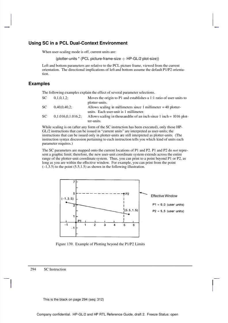
8/12/2019 HPGL2-RTL ReferenceGuide 5961-3526 540pages Sep96
http://slidepdf.com/reader/full/hpgl2-rtl-referenceguide-5961-3526-540pages-sep96 312/539
294
This is the black on page 294 (seq: 312)
Company confidential. HP-GL/2 and HP RTL Reference Guide, draft 2. Freeze Status: open
Using SC in a PCL Dual-Context Environment
When user-scaling mode is off, current units are:
(plotter-units * (PCL picture-frame-size HP-GL/2 plot-size))
Left and bottom parameters are relative to the PCL picture frame, viewed from the currentorientation. The directional implications of left and bottom assume the default P1/P2 orienta-tion.
Examples
The following examples explain the effect of several parameter selections.
SC 0,1,0,1,2; Moves the origin to P1 and establishes a 1:1 ratio of user-units to
plotter-units.
SC 0,40,0,40,2; Allows scaling in millimeters since 1 millimeter = 40 plotter-
units. Each user-unit is 1 millimeter.SC 0,1.016,0,1.016,2; Allows scaling in thousandths of an inch since 1 inch = 1016 plot-
ter-units.
While scaling is on (after any form of the SC instruction has been executed), only those HP-GL/2 instructions that can be issued in “current units” are interpreted as user-units; theinstructions that can be issued only in plotter-units are still interpreted as plotter-units. (Theinstruction syntax discussion pertaining to each instruction tells you which kind of units eachparameter requires.)
The SC parameters are mapped onto the current locations of P1 and P2. P1 and P2 do not repre-sent a graphic limit; therefore, the new user-unit coordinate system extends across the entirerange of the plotter-unit coordinate system. Thus, you can print to a point beyond P1 or P2, aslong as you are within the effective window. For example, you can print from the point(–1,3.5) to the point (5.5,1.5) as shown in the following illustration.
Figure 139. Example of Plotting beyond the P1/P2 Limits
SC Instruction
8/12/2019 HPGL2-RTL ReferenceGuide 5961-3526 540pages Sep96
http://slidepdf.com/reader/full/hpgl2-rtl-referenceguide-5961-3526-540pages-sep96 313/539
295
This is the black on page 295 (seq: 313)
Company confidential. HP-GL/2 and HP RTL Reference Guide, draft 2. Freeze Status: open
Related Instructions
IP Input P1 and P2
IR Input Relative P1 and P2IW Input Window
Possible Error Conditions
Error Condition Error Number Printer or Plotter Response
More than 7 parameters 2 Executes first 7 parameters
For types 0 or 1:More than 6 or less than 4 parameters
2 Ignores instruction
For type 2:Other than 5 parameters
2 Ignores instruction
XMIN=XMAX or YMIN=YMAX ornumber out of range
3 Ignores instruction
XFACTOR=0 or YFACTOR=0 3 Ignores instruction
This is the blue on page 295 (seq: 313)
SC Instruction
I N S T R U C T I O N S
H P - G L / 2
8/12/2019 HPGL2-RTL ReferenceGuide 5961-3526 540pages Sep96
http://slidepdf.com/reader/full/hpgl2-rtl-referenceguide-5961-3526-540pages-sep96 314/539
296
This is the black on page 296 (seq: 314)
Company confidential. HP-GL/2 and HP RTL Reference Guide, draft 2. Freeze Status: open
SD, Standard Font Definition
Purpose
To define the standard character set (font) and its characteristics: symbol set identification, fontspacing, pitch, height, posture, stroke weight, and typeface. To define an alternate font, use theAD instruction.
Syntax
SD kind,value...[,kind,value] [;]or
SD [;]
Á Á Á Á Á Á Á
Á Á Á Á Á Á Á
Parameter Á Á Á Á Á Á
Á Á Á Á Á Á
Format Á Á Á Á Á Á Á Á
Á Á Á Á Á Á Á Á
Functional Range Á Á Á Á Á Á Á Á
Á Á Á Á Á Á Á Á
Parameter Default
Á Á Á Á Á Á Á
Á Á Á Á Á Á Á
kind Á Á Á Á Á Á
Á Á Á Á Á Á
clamped integerÁ Á Á Á Á Á Á Á
Á Á Á Á Á Á Á Á
1 to 7 Á Á Á Á Á Á Á Á
Á Á Á Á Á Á Á Á
no default
Á Á Á Á Á Á Á
Á Á Á Á Á Á Á
valueÁ Á Á Á Á Á
Á Á Á Á Á Á
clamped realÁ Á Á Á Á Á Á Á
Á Á Á Á Á Á Á Á
kind -dependent*Á Á Á Á Á Á Á Á
Á Á Á Á Á Á Á Á
kind -dependent*
* Refer to the table following the parameter descriptions.
Group
This instruction is in the Character Group.
Use
This instruction is similar to the AD (Alternate Font Definition) instruction (see page 106) thatdefines a secondary HP-GL/2 font. The SD instruction defines the standard HP-GL/2 font andits characteristics: font spacing, pitch, height, posture, stroke weight, and typeface. It allowsthe font characteristics to be assigned to the primary font definition. Use SD to set up the stan-dard font that you can easily access when labeling.
No Parameters: Defaults the standard font characteristics to that of the device-dependentdefault scalable font, not a bitmap font.
kind: Specifies the characteristic for which you are setting a value (see the followingtable).
value: Defines the properties of the characteristic specified by the kind parameter.
Note: When selecting fonts, the different characteristics (symbol set, spacing, pitch, etc.) areprioritized as shown in the table above, with symbol set being the highest priority and typeface
being the lowest. The font selection priority is the same for HP-GL/2 as for PCL font selection.For more information about the priority of font characteristics, see How Your Device SelectsFonts on page 63.
The tables in Appendix C: Font Definitions on page 477 list the kind parameters with theirassociated values (note that these tables are also valid for the AD [Alternate Font Definition]instruction). For kinds 1 and 7, your device may support values other than those listed there.Refer to your User’s Guide or HP-GL/2 option manual for more information about the attrib-utes and values supported.
This is the blue on page 296 (seq: 314)
SD Instruction
8/12/2019 HPGL2-RTL ReferenceGuide 5961-3526 540pages Sep96
http://slidepdf.com/reader/full/hpgl2-rtl-referenceguide-5961-3526-540pages-sep96 315/539
297
This is the black on page 297 (seq: 315)
Company confidential. HP-GL/2 and HP RTL Reference Guide, draft 2. Freeze Status: open
Any combination of kind, value parameters is allowed; the last kind specified prevails.
Kind Attribute Range of Values Default Value Description
1 Character set device-dependent 277 Roman-8
2 Font Spacing 0 (fixed),1 (proportional)
device-dependent fixed spacing
3 Pitch >0 to 32 767 (valid to2 decimal places)
device-dependent characters per inch
4 Height 0 to 32 767 device-dependent font point size
5 Posture 0 to 32 767 device-dependent upright or italic
6 Stroke Weight –7 to 7, 9999 0 normal
7 Typeface device-dependent device-dependent scalable font
The IN (Initialize) and DF (Default Values) instructions restore default primary font attributes.
Related Instructions
AD Alternate Font DefinitionDT Define Label TerminatorFI Select Primary FontFN Select Secondary FontLB LabelSA Select Alternate FontSB Scalable or Bitmap FontsSI Absolute Character SizeSR Relative Character SizeSS Select Standard FontTD Transparent Data
Example
The instruction “SD1,21,2,1,4,25,5,0,6,3,7,51;” designates a 25-point Gill Sans Bold font in theASCII symbol set (use the Select Standard Font (SS) instruction to select this font after it isdesignated):
SD 1,21 Symbol set—US ASCII2,1 Spacing—proportional4,25 Height—25-point5,0 Posture—upright6,3 Stroke weight—bold7,51; Typeface—Gill Sans
Note that the pitch parameter is missing in the above instruction because the designated font isproportionally spaced.
SD Instruction
This is the blue on page 297 (seq: 315)
SD Instruction
I N S T R U C T I O N S
H P - G L / 2
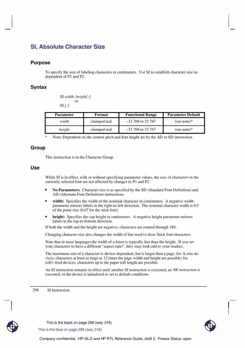
8/12/2019 HPGL2-RTL ReferenceGuide 5961-3526 540pages Sep96
http://slidepdf.com/reader/full/hpgl2-rtl-referenceguide-5961-3526-540pages-sep96 316/539
298
This is the black on page 298 (seq: 316)
Company confidential. HP-GL/2 and HP RTL Reference Guide, draft 2. Freeze Status: open
SI, Absolute Character Size
Purpose
To specify the size of labeling characters in centimeters. Use SI to establish character size in-dependent of P1 and P2.
Syntax
SI width, height[;]or
SI [;]
Á Á Á Á Á Á Á
Á Á Á Á Á Á Á
ParameterÁ Á Á Á Á Á
Á Á Á Á Á Á
FormatÁ Á Á Á Á Á Á Á
Á Á Á Á Á Á Á Á
Functional RangeÁ Á Á Á Á Á Á Á
Á Á Á Á Á Á Á Á
Parameter DefaultÁ Á Á Á Á Á Á
Á Á Á Á Á Á Á
width
Á Á Á Á Á Á
Á Á Á Á Á Á
clamped real
Á Á Á Á Á Á Á Á
Á Á Á Á Á Á Á Á
–32 768 to 32 767
Á Á Á Á Á Á Á Á
Á Á Á Á Á Á Á Á
(see note)*Á Á Á Á Á Á Á
Á Á Á Á Á Á Á
Á Á Á Á Á Á Á
height Á Á Á Á Á Á
Á
Á Á Á Á Á
Á Á Á Á Á Á
clamped realÁ Á Á Á Á Á Á Á
Á
Á Á Á Á Á Á Á
Á Á Á Á Á Á Á Á
–32 768 to 32 767Á Á Á Á Á Á Á Á
Á
Á Á Á Á Á Á Á
Á Á Á Á Á Á Á Á
(see note)*
* Note: Dependent on the current pitch and font height set by the AD or SD instruction.
Group
This instruction is in the Character Group.
Use
While SI is in effect, with or without specifying parameter values, the size of characters in the
currently selected font are not affected by changes in P1 and P2.
No Parameters: Character size is as specified by the SD (Standard Font Definition) andAD (Alternate Font Definition) instructions.
width: Specifies the width of the nominal character in centimeters. A negative widthparameter mirrors labels in the right-to-left direction. The nominal character width is 0.5of the point size (0.67 for the stick font).
height: Specifies the cap height in centimeters. A negative height parameter mirrorslabels in the top-to-bottom direction.
If both the width and the height are negative, characters are rotated through 180.
Changing character size also changes the width of line used to draw Stick font characters.
Note that in most languages the width of a letter is typically less than the height. If you setyour characters to have a different “aspect ratio”, they may look odd to your readers.
The maximum size of a character is device-dependent, but is larger than a page; for A-size de-vices, characters at least as large as 12 times the page width and height are possible; forroll1–feed devices, characters up to the paper roll length are possible.
An SI instruction remains in effect until another SI instruction is executed, an SR instruction isexecuted, or the device is initialized or set to default conditions.
This is the blue on page 298 (seq: 316)
SI Instruction
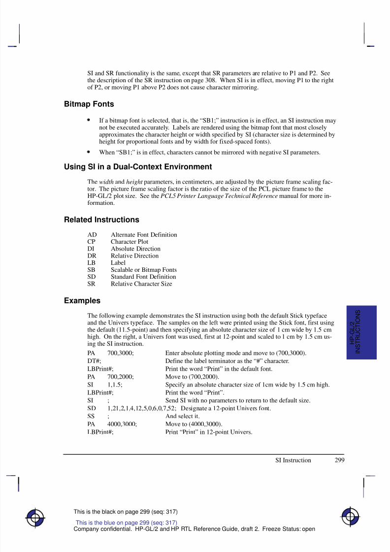
8/12/2019 HPGL2-RTL ReferenceGuide 5961-3526 540pages Sep96
http://slidepdf.com/reader/full/hpgl2-rtl-referenceguide-5961-3526-540pages-sep96 317/539
299
This is the black on page 299 (seq: 317)
Company confidential. HP-GL/2 and HP RTL Reference Guide, draft 2. Freeze Status: open
SI and SR functionality is the same, except that SR parameters are relative to P1 and P2. Seethe description of the SR instruction on page 308. When SI is in effect, moving P1 to the rightof P2, or moving P1 above P2 does not cause character mirroring.
Bitmap Fonts
If a bitmap font is selected, that is, the “SB1;” instruction is in effect, an SI instruction maynot be executed accurately. Labels are rendered using the bitmap font that most closelyapproximates the character height or width specified by SI (character size is determined byheight for proportional fonts and by width for fixed-spaced fonts).
When “SB1;” is in effect, characters cannot be mirrored with negative SI parameters.
Using SI in a Dual-Context Environment
The width and height parameters, in centimeters, are adjusted by the picture frame scaling fac-tor. The picture frame scaling factor is the ratio of the size of the PCL picture frame to theHP-GL/2 plot size. See the PCL5 Printer Language Technical Reference manual for more in-formation.
Related Instructions
AD Alternate Font DefinitionCP Character PlotDI Absolute DirectionDR Relative DirectionLB LabelSB Scalable or Bitmap FontsSD Standard Font DefinitionSR Relative Character Size
Examples
The following example demonstrates the SI instruction using both the default Stick typefaceand the Univers typeface. The samples on the left were printed using the Stick font, first usingthe default (11.5-point) and then specifying an absolute character size of 1 cm wide by 1.5 cmhigh. On the right, a Univers font was used, first at 12-point and scaled to 1 cm by 1.5 cm us-ing the SI instruction.
PA 700,3000; Enter absolute plotting mode and move to (700,3000).
DT#; Define the label terminator as the “#” character.
LBPrint#; Print the word “Print” in the default font.
PA 700,2000; Move to (700,2000).
SI 1,1.5; Specify an absolute character size of 1cm wide by 1.5 cm high.LBPrint#; Print the word “Print”.
SI ; Send SI with no parameters to return to the default size.
SD 1,21,2,1,4,12,5,0,6,0,7,52; Designate a 12-point Univers font.
SS ; And select it.
PA 4000,3000; Move to (4000,3000).
LBPrint#; Print “Print” in 12-point Univers.
This is the blue on page 299 (seq: 317)
SI Instruction
I N S T R U C T I O N S
H P - G L / 2
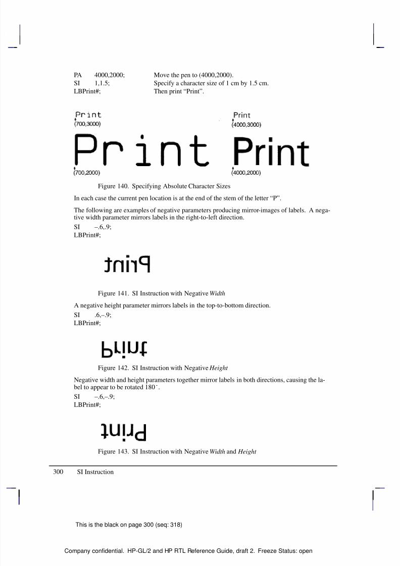
8/12/2019 HPGL2-RTL ReferenceGuide 5961-3526 540pages Sep96
http://slidepdf.com/reader/full/hpgl2-rtl-referenceguide-5961-3526-540pages-sep96 318/539
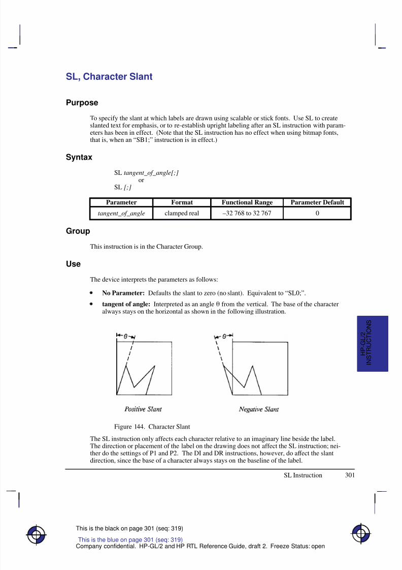
8/12/2019 HPGL2-RTL ReferenceGuide 5961-3526 540pages Sep96
http://slidepdf.com/reader/full/hpgl2-rtl-referenceguide-5961-3526-540pages-sep96 319/539
301
This is the black on page 301 (seq: 319)
Company confidential. HP-GL/2 and HP RTL Reference Guide, draft 2. Freeze Status: open
SL, Character Slant
Purpose
To specify the slant at which labels are drawn using scalable or stick fonts. Use SL to createslanted text for emphasis, or to re-establish upright labeling after an SL instruction with param-eters has been in effect. (Note that the SL instruction has no effect when using bitmap fonts,that is, when an “SB1;” instruction is in effect.)
Syntax
SL tangent_of_angle[;]or
SL [;]
Á Á Á Á Á Á Á
Á Á Á Á Á Á Á
ParameterÁ Á Á Á Á Á Á
Á Á Á Á Á Á Á
FormatÁ Á Á Á Á Á Á Á
Á Á Á Á Á Á Á Á
Functional RangeÁ Á Á Á Á Á Á
Á Á Á Á Á Á Á
Parameter DefaultÁ Á Á Á Á Á Á
Á
Á Á Á Á Á Á
Á Á Á Á Á Á Á
tangent_of_angle
Á Á Á Á Á Á Á
Á
Á Á Á Á Á Á
Á Á Á Á Á Á Á
clamped real
Á Á Á Á Á Á Á Á
Á
Á Á Á Á Á Á Á
Á Á Á Á Á Á Á Á
–32 768 to 32 767
Á Á Á Á Á Á Á
Á
Á Á Á Á Á Á
Á Á Á Á Á Á Á
0
Group
This instruction is in the Character Group.
Use
The device interprets the parameters as follows:
No Parameter: Defaults the slant to zero (no slant). Equivalent to “SL0;”.
tangent of angle: Interpreted as an angle from the vertical. The base of the characteralways stays on the horizontal as shown in the following illustration.
Figure 144. Character Slant
The SL instruction only affects each character relative to an imaginary line beside the label.The direction or placement of the label on the drawing does not affect the SL instruction; nei-ther do the settings of P1 and P2. The DI and DR instructions, however, do affect the slantdirection, since the base of a character always stays on the baseline of the label.
This is the blue on page 301 (seq: 319)
SL Instruction
I N S T R U C T I O N S
H P - G L / 2
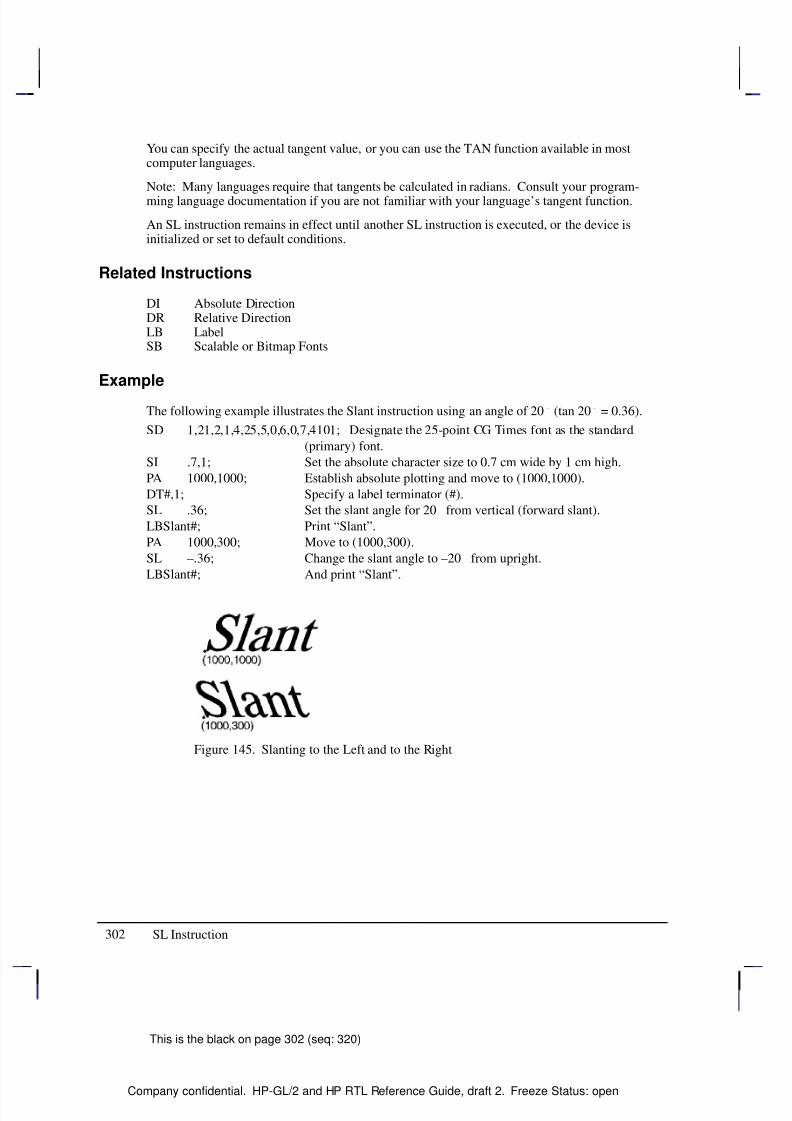
8/12/2019 HPGL2-RTL ReferenceGuide 5961-3526 540pages Sep96
http://slidepdf.com/reader/full/hpgl2-rtl-referenceguide-5961-3526-540pages-sep96 320/539
8/12/2019 HPGL2-RTL ReferenceGuide 5961-3526 540pages Sep96
http://slidepdf.com/reader/full/hpgl2-rtl-referenceguide-5961-3526-540pages-sep96 321/539
303
This is the black on page 303 (seq: 321)
Company confidential. HP-GL/2 and HP RTL Reference Guide, draft 2. Freeze Status: open
SM, Symbol Mode
Purpose
To draw the specified symbol at each X,Y coordinate point using the PA, PD, PE, PR, and PUinstructions. Use SM to create scatter-grams, indicate points on geometric drawings, and differ-entiate data points on multi-line graphs.
Syntax
SM character[;]or
SM charactercharacter2[;]or
SM [;]
Á Á Á Á Á Á Á
Á Á Á Á Á Á Á
ParameterÁ Á Á Á Á Á Á
Á Á Á Á Á Á Á
FormatÁ Á Á Á Á Á Á Á
Á Á Á Á Á Á Á Á
Functional RangeÁ Á Á Á Á Á Á
Á Á Á Á Á Á Á
Parameter DefaultÁ Á Á Á Á Á Á
Á Á Á Á Á Á Á
Á
Á Á Á Á Á Á
Á Á Á Á Á Á Á
Á Á Á Á Á Á Á
character
character2*
Á Á Á Á Á Á Á
Á Á Á Á Á Á Á
Á
Á Á Á Á Á Á
Á Á Á Á Á Á Á
Á Á Á Á Á Á Á
characterÁ Á Á Á Á Á Á Á
Á Á Á Á Á Á Á Á
Á
Á Á Á Á Á Á Á
Á Á Á Á Á Á Á Á
Á Á Á Á Á Á Á Á
Decimal codes 1 to 255(most printing charac-
ters except 0, 5, 27, and59)**
Á Á Á Á Á Á Á
Á Á Á Á Á Á Á
Á
Á Á Á Á Á Á
Á Á Á Á Á Á Á
Á Á Á Á Á Á Á
no default
* Character2 is only valid in 16-bit mode (see the LM instruction on page 208). In 16-bitmode, both character and character2 are needed to specify the character. In 8-bit mode,character2 would be considered the start of a new instruction.
** Decimal code 59 (the semicolon) is an HP-GL/2 terminator and cannot be used as a symbolin any symbol set. Use it only to cancel symbol mode (“SM;”).
Group
This instruction is in the Line and Fill Attributes Group.
Use
The SM instruction draws the specified symbol at each X,Y coordinate point for subsequent PA,PD, PE, PR, and PU instructions. The SM instruction includes an automatic pen down; afterthe symbol is drawn, the pen position and any dashed-line residue are restored.
No Parameter: Terminates symbol mode.
character, character2: Draws the specified character centered at each subsequent X,Y
coordinate. The symbol is drawn in addition to the usual function of each HP-GL/2instruction.
The character is drawn in the font selected at the time the vectors are drawn. If you change to anew symbol set, the character changes to the corresponding character from the new symbol set.The character fill (CF), size (SI and SR), slant (SL), and direction (DI and DR) instructions af-fect how the character is drawn. Specifying a non-printing character cancels symbol mode. If downloadable characters have been defined (see DL) they can be used in symbol mode plotting.
This is the blue on page 303 (seq: 321)
SM Instruction
I N S T R U C T I O N S
H P - G L / 2
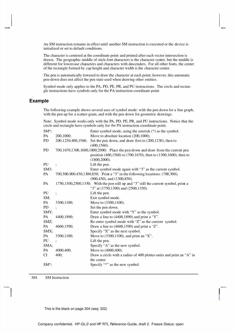
8/12/2019 HPGL2-RTL ReferenceGuide 5961-3526 540pages Sep96
http://slidepdf.com/reader/full/hpgl2-rtl-referenceguide-5961-3526-540pages-sep96 322/539
304
This is the black on page 304 (seq: 322)
Company confidential. HP-GL/2 and HP RTL Reference Guide, draft 2. Freeze Status: open
An SM instruction remains in effect until another SM instruction is executed or the device isinitialized or set to default conditions.
The character is centered at the coordinate point and printed after each vector intersection isdrawn. The geographic middle of stick-font characters is the character center, but the middle isdifferent for lowercase characters and characters with descenders. For all other fonts, the centerof the rectangle formed by cap height and character width is the character center.
The pen is automatically lowered to draw the character at each point; however, this automaticpen-down does not affect the pen state used when drawing other entities.
Symbol mode only applies to the PA, PD, PE, PR, and PU instructions. The circle and rectan-gle instructions have symbols only for the PA instruction coordinate point.
Example
The following example shows several uses of symbol mode: with the pen down for a line graph,with the pen up for a scatter-gram, and with the pen down for geometric drawings.
Note: Symbol mode works only with the PA, PD, PE, PR, and PU instructions. Notice that thecircle and rectangle have symbols only for the PA instruction coordinate point.
SM*; Enter symbol mode, using the asterisk (*) as the symbol.
PA 200,1000; Move to absolute location (200,1000).
PD 200,1230,400,1560; Set the pen down, and draw first to (200,1230), then to
(400,1560).
PD 700,1670,1300,1600,1800,2000; Place the pen down and draw from the current pen
position (400,1560) to (700,1670), then to (1300,1600), then to
(1800,2000).
PU ; Lift the pen.
SM3; Enter symbol mode again with “3” as the current symbol.
PA 700,500,900,450,1300,850; Print a “3” in the following locations: (700,500),(900,450), and (1300,850).
PA 1750,1300,2500,1350; With the pen still up and “3” still the current symbol, print a
“3” at (1750,1300) and (2500,1350).
PU ; Lift the pen.
SM; Exit symbol mode.
PA 3300,1100; Move to (3300,1100).
PD ; Set the pen down.
SMY; Enter symbol mode with “Y” as the symbol.
PA 4400,1890; Draw a line to (4400,1890) and print a “Y”.
SMZ; Re-enter symbol mode with “Z” as the current symbol.
PA 4600,1590; Draw a line to (4600,1590) and print a “Z”.
SMX; Specify “X” as the next symbol.
PA 3300,1100; Move to (3300,1100), and print an “X”.
PU ; Lift the pen.
SMA; Specify “A” as the new symbol.
PA 4000,400; Move to (4000,400).
CI 400; Draw a circle with a radius of 400 plotter-units and print an “A” in
the center.
SM*; Specify “*” as the new symbol.
SM Instruction
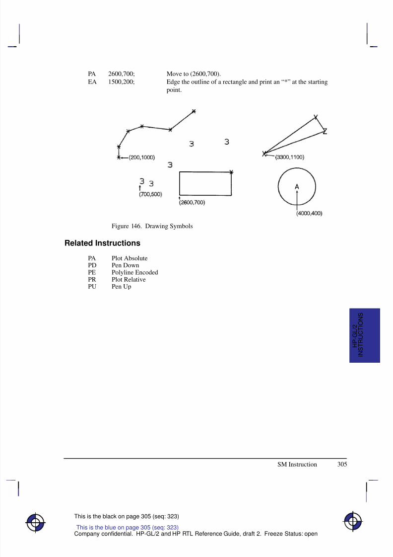
8/12/2019 HPGL2-RTL ReferenceGuide 5961-3526 540pages Sep96
http://slidepdf.com/reader/full/hpgl2-rtl-referenceguide-5961-3526-540pages-sep96 323/539
305
This is the black on page 305 (seq: 323)
Company confidential. HP-GL/2 and HP RTL Reference Guide, draft 2. Freeze Status: open
PA 2600,700; Move to (2600,700).
EA 1500,200; Edge the outline of a rectangle and print an “*” at the starting
point.
Figure 146. Drawing Symbols
Related Instructions
PA Plot AbsolutePD Pen DownPE Polyline EncodedPR Plot RelativePU Pen Up
This is the blue on page 305 (seq: 323)
SM Instruction
I N S T R U C T I O N S
H P - G L / 2
8/12/2019 HPGL2-RTL ReferenceGuide 5961-3526 540pages Sep96
http://slidepdf.com/reader/full/hpgl2-rtl-referenceguide-5961-3526-540pages-sep96 324/539
306
This is the black on page 306 (seq: 324)
Company confidential. HP-GL/2 and HP RTL Reference Guide, draft 2. Freeze Status: open
SP, Select Pen
Purpose
To select the device’s logical pen for subsequent plotting. An SP instruction must be includedat the beginning of each instruction sequence to enable the device to draw.
Syntax
SP pen_number[;]or
SP [;]
Á Á Á Á Á Á Á
Á Á Á Á Á Á Á
ParameterÁ Á Á Á Á Á
Á Á Á Á Á Á
FormatÁ Á Á Á Á Á Á Á
Á Á Á Á Á Á Á Á
Functional RangeÁ Á Á Á Á Á Á Á
Á Á Á Á Á Á Á Á
Parameter DefaultÁ Á Á Á Á Á Á
Á Á Á Á Á Á Á
Á Á Á Á Á Á Á
pen_number
Á Á Á Á Á Á
Á Á Á Á Á Á
Á Á Á Á Á Á
integer
Á Á Á Á Á Á Á Á
Á Á Á Á Á Á Á Á
Á Á Á Á Á Á Á Á
device-dependent (at least –223 to 223 – 1)
Á Á Á Á Á Á Á Á
Á Á Á Á Á Á Á Á
Á Á Á Á Á Á Á Á
0 (no pen)
Group
This instruction is in the Line and Fill Attributes Group.
Use
Although your device may not have physical pens, for the purpose of compatibility it has “log-ical” pens which you must select to print your drawing.
No Parameters: Equivalent to “SP0”.
pen_number: Selects the device’s logical pen. The device will not draw unless an SP issent.
0 Selects pen 0 on raster devices. For pen plotters, stores the pen in the carousel andsubsequent plotting commands are not drawn.
>0 Selects the pen number. In raster devices, different pen numbers may representpens of the same color but with different widths.
The modulo function is applied if the pen number is greater than the current pal-ette size or the maximum number of pens in the device:
for raster devices,pen_used = ((pen_number – 1) MOD (number_of_pens –1)) + 1
for pen plotters,pen_used = ((pen_number – 1) MOD (number_of_pens)) + 1
For monochrome devices, if pen_number >0 a black pen is selected.
Pen 0 defaults to white on black-and-white devices; other colors default to graylevels.
Use the PW (Pen Width) instruction to change the line width. You may change widths as oftenas you like, without sending an SP instruction again.
This is the blue on page 306 (seq: 324)
SP Instruction
8/12/2019 HPGL2-RTL ReferenceGuide 5961-3526 540pages Sep96
http://slidepdf.com/reader/full/hpgl2-rtl-referenceguide-5961-3526-540pages-sep96 325/539
307
This is the black on page 307 (seq: 325)
Company confidential. HP-GL/2 and HP RTL Reference Guide, draft 2. Freeze Status: open
Note: If you are not using the TR (Transparency Mode) instruction, white is always transpar-ent; a transparent pen is the same as no pen. For more information on the TR instruction seepage 318.
The default black-and-white palette consists of two pens: black and white. The default colorraster palette has eight pens defined below; pen 0 is selected at power-up.
Number of Pens in Device Pen Number Color
2 0 White
1 Black
8 0 White
1 Black
2 Red
3 Green
4 Yellow
5 Blue
6 Magenta
7 Cyan
SP clears the pattern residue and terminates any sequence of continuous vectors (see the LAand LT instructions).
Related Instructions
PW, Pen WidthTR, Transparency ModeWU, Pen Width Unit Selection
This is the blue on page 307 (seq: 325)
SP Instruction
I N S T R U C T I O N S
H P - G L / 2
8/12/2019 HPGL2-RTL ReferenceGuide 5961-3526 540pages Sep96
http://slidepdf.com/reader/full/hpgl2-rtl-referenceguide-5961-3526-540pages-sep96 326/539
308
This is the black on page 308 (seq: 326)
Company confidential. HP-GL/2 and HP RTL Reference Guide, draft 2. Freeze Status: open
SR, Relative Character Size
Purpose
To specify the size of characters as a percentage of the distance between P1 and P2. Use SR toestablish relative character size so that if the P1/P2 distance changes, the character size adjuststo occupy the same relative amount of space.
Syntax
SR width,height[;]or
SR [;]
Á Á Á Á Á Á Á
Á Á Á Á Á Á Á
Parameter Á Á Á Á Á Á
Á Á Á Á Á Á
Format Á Á Á Á Á Á Á Á
Á Á Á Á Á Á Á Á
Functional Range Á Á Á Á Á Á Á Á
Á Á Á Á Á Á Á Á
Parameter Default
Á Á Á Á Á Á Á
Á Á Á Á Á Á Á
width Á Á Á Á Á Á
Á Á Á Á Á Á
clamped real Á Á Á Á Á Á Á Á
Á Á Á Á Á Á Á Á
–32 768 to 32 767 Á Á Á Á Á Á Á Á
Á Á Á Á Á Á Á Á
0.75% of P2X–P1X
Á Á Á Á Á Á Á
Á Á Á Á Á Á Á
height Á Á Á Á Á Á
Á Á Á Á Á Á
clamped realÁ Á Á Á Á Á Á Á
Á Á Á Á Á Á Á Á
–32 768 to 32 767Á Á Á Á Á Á Á Á
Á Á Á Á Á Á Á Á
1.5% of P2Y–P1Y
Group
This instruction is in the Character Group.
Use
While the SR instruction is in effect (with or without parameters), changes in P1 and P2 affectthe size of characters in the currently selected font.
No Parameters: Defaults the relative character width to 0.75% of the distance(P2X – P1X) and the height to 1.5% of the distance (P2Y – P1Y).
width: Sets the character width to the specified percentage of the distance between theX-coordinates of P1 and P2. A negative width parameter mirrors labels in the right-to-leftdirection.
height: Sets the character height to the specified percentage of the distance between theY-coordinates of P1 and P2. A negative height parameter mirrors labels in the top-to-bot-tom direction.
If both the width and the height are negative, characters are rotated through 180.
Note: Changing character size also changes the stroke weight of labels; the device adjusts char-acters relative to changes in P1/P2. As long as the aspect ratio remains the same with changes
in P1/P2, characters will have the same appearance relative to the new P1/P2 rectangle.
The character size you specify with SR is a percentage of (P2X – P1X) and (P2Y – P1Y). Thedevice calculates the actual character width and height from the specified parameters as fol-lows:
actual width = (width parameter/100) x (P2X – P1X)
actual height = (height parameter/100) x (P2Y – P1Y)
This is the blue on page 308 (seq: 326)
SR Instruction
8/12/2019 HPGL2-RTL ReferenceGuide 5961-3526 540pages Sep96
http://slidepdf.com/reader/full/hpgl2-rtl-referenceguide-5961-3526-540pages-sep96 327/539
309
This is the black on page 309 (seq: 327)
Company confidential. HP-GL/2 and HP RTL Reference Guide, draft 2. Freeze Status: open
For example, suppose P1 and P2 are located at (–6956,–4388) and (6956,4388), respectively. If you establish relative sizing and specify a width of 2 and a height of 3.5, the device determinesthe actual character size as follows:
width = (2/100) x (6956 – (–6956)) = 278.24 plotter-units or 0.695 cm
height = (3.5/100) x (4388 – ( –4388) ) = 307.16 plotter-units or 0.768 cm
If you changed P1 and P2 settings to (100,100) and (5000,5000), but did not change the SR pa-rameters, the character size would change as follows:
width = (2/100) x (5000 – 100) = 98 plotter-units or 0.245 cm
height = (3.5/100) x (5000 – 100) = 171.5 plotter-units or 0.429 cm
Note that in most languages the width of a letter is typically less than the height. If you setyour characters to have a different “aspect ratio”, they may look odd to your readers.
Note: Either negative SR parameters or switching the relative position of P1 and P2 produces
mirror-images of labels. When P1 is in the lower left and P2 is in the upper right, the SRinstruction gives the same mirroring results as the SI instruction. However, if you move P1 tothe right of P2, characters are mirrored right-to-left; when you move P1 above P2, charactersare mirrored top-to-bottom. When both of these situations occur (using negative parameters inthe SR instruction with an unusual P1/P2 position) double mirroring may result in either direc-tion, in which case the two inversions cancel, and lettering appears normal.
An SR instruction remains in effect until another SR instruction is executed, an SI instruction isexecuted, or the device is initialized or set to default conditions.
If a bitmap font (“SB1;”) is selected, SR may not accurately transform characters; labels arerendered in the font most closely approximating the height specified by SR. Negative parame-ters or unusual P1/P2 locations do not cause mirroring.
After SR is in effect, “SI;” must be sent to use the size specified by SD or AD.
Related Instructions
CP Character PlotDI Absolute DirectionDR Relative DirectionIP Input P1 and P2IR Input Relative P1 and P2SB Scalable or Bitmap FontsSI Absolute Character Size
Examples
The following example first shows a label with a character size relative to P1 and P2 (SR).Next, the locations of P1 and P2 are changed; then, the character size percentages are specified.Notice that the new character size has equal parameters of 2.5; because the P1/P2 area issquare, the resulting characters are square.
IP –6956,–4388,6956,4388; Set P1 at (–6956,–4388) and P2 at (6956,4388).
DT@; Specify “@” as the label terminator.
SR ; Default the character size as a percentage of the P1/P2 rectangle.
PA 0,2700; Move the pen to (0,2700).
This is the blue on page 309 (seq: 327)
SR Instruction
I N S T R U C T I O N S
H P - G L / 2
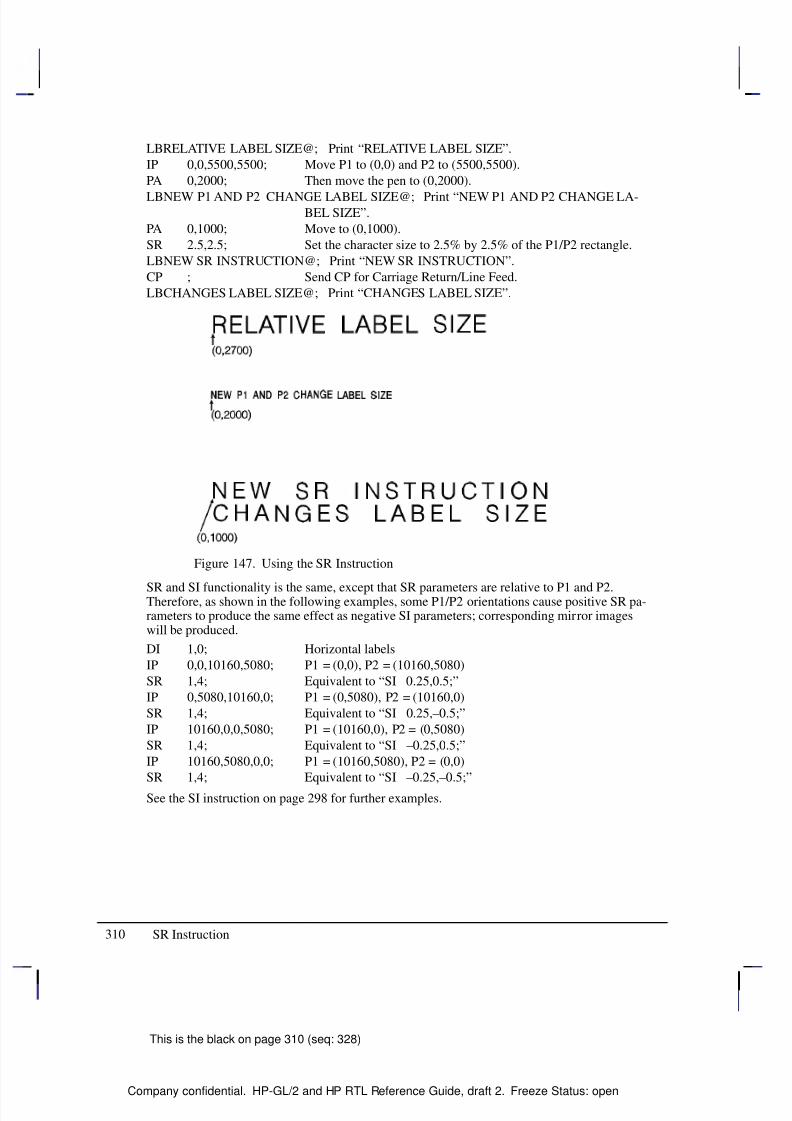
8/12/2019 HPGL2-RTL ReferenceGuide 5961-3526 540pages Sep96
http://slidepdf.com/reader/full/hpgl2-rtl-referenceguide-5961-3526-540pages-sep96 328/539
8/12/2019 HPGL2-RTL ReferenceGuide 5961-3526 540pages Sep96
http://slidepdf.com/reader/full/hpgl2-rtl-referenceguide-5961-3526-540pages-sep96 329/539
311
This is the black on page 311 (seq: 329)
Company confidential. HP-GL/2 and HP RTL Reference Guide, draft 2. Freeze Status: open
SS, Select Standard Font
Purpose
To select the standard font (already designated by the SD (Standard Font Definition) instruc-tion) for subsequent labeling. Use the SS instruction to shift from the currently selectedalternate font to the designated standard font.
Syntax
SS [;]
Group
This instruction is in the Character Group.
Use
The SS instruction tells the device to print subsequent labeling instructions using charactersfrom the standard symbol set designated by the SD instruction. The SS instruction is equivalentto using the Shift In control character (, ASCII decimal code 15) within a label string.
The default-designated standard font is the Stick font, and uses symbol set 277 (Roman-8).This font is in effect when the device is initialized or set to default conditions. The SS instruc-tion remains in effect until an SA instruction or a Shift Out control character (, ASCIIdecimal code 14) is executed.
Related InstructionsAD Alternate Font DefinitionDT Define Label TerminatorFI Select Primary FontFN Select Secondary FontLB LabelSA Select Alternate FontSD Standard Font Definition
This is the blue on page 311 (seq: 329)
SS Instruction
I N S T R U C T I O N S
H P - G L / 2
8/12/2019 HPGL2-RTL ReferenceGuide 5961-3526 540pages Sep96
http://slidepdf.com/reader/full/hpgl2-rtl-referenceguide-5961-3526-540pages-sep96 330/539
312
This is the black on page 312 (seq: 330)
Company confidential. HP-GL/2 and HP RTL Reference Guide, draft 2. Freeze Status: open
ST, Sort
Purpose
To specify how the device is to sort vectors for plotting. Raster devices ignore this instruction.
Syntax
ST switches[;]or
ST [;]
Á Á Á Á Á Á Á
ParameterÁ Á Á Á Á Á
FormatÁ Á Á Á Á Á Á Á
Functional RangeÁ Á Á Á Á Á Á Á
Parameter DefaultÁ Á Á Á Á Á Á
Á Á Á Á Á Á Á
Á Á Á Á Á Á Á
switches
Á Á Á Á Á Á
Á
Á Á Á Á Á
Á Á Á Á Á Á
clamped integerÁ Á Á Á Á Á Á Á
Á
Á Á Á Á Á Á Á
Á Á Á Á Á Á Á Á
–1,0, and any sum of 1,
2, and 4 (1 through 7)
Á Á Á Á Á Á Á Á
Á
Á Á Á Á Á Á Á
Á Á Á Á Á Á Á Á
0
Group
This instruction is in the Technical Graphics Extension.
Use
The sorting switches are device-dependent and vary according to the hardware technology,buffer size, and plotting/CPU speed trade-offs.
No Parameter: Defaults the sorting to a device-dependent switch. Refer to the documen-tation for your device or HP-GL/2 option to determine what switches are supported and
which is the default.
switches: Determines sorting as follows:
–1 Turns on all sorting (or optimal combination).
0 Turns off all sorting; plots vectors in the order they are received.
1 Pen sorting; vectors are sorted by pen color rather than in the order in which theywere received.
2 End-point swap (bidirectional plotting); swaps successive vector end points tominimize pen-up moves.
4 Geographic sorting; sorts all vectors by their geographic area before moving toanother area.
There are no out-of-range parameters (within the clamped integer constraint). The switchespertinent to the device are used, and others are ignored.
This is the blue on page 312 (seq: 330)
ST Instruction
8/12/2019 HPGL2-RTL ReferenceGuide 5961-3526 540pages Sep96
http://slidepdf.com/reader/full/hpgl2-rtl-referenceguide-5961-3526-540pages-sep96 331/539
313
This is the black on page 313 (seq: 331)
Company confidential. HP-GL/2 and HP RTL Reference Guide, draft 2. Freeze Status: open
SV, Screened Vectors
Purpose
To select the type of screening (area fill) to be applied to vectors. Options include lines, hatch-ing patterns (fill types 3 and 4), arcs, circles, edges of polygons, rectangles, wedges and PCLand HP RTL user-defined patterns. SV does not affect solid fill types, stroked characters, oredges of characters. Pen plotters ignore this instruction.
Syntax
SV screen_type [,option1 [,option2]][;]or
SV [;]
Á Á Á Á Á Á Á
Á Á Á Á Á Á Á
ParameterÁ Á Á Á Á Á Á
Á Á Á Á Á Á Á
FormatÁ Á Á Á Á Á Á Á
Á Á Á Á Á Á Á Á
Functional RangeÁ Á Á Á Á Á Á
Á Á Á Á Á Á Á
Parameter DefaultÁ Á Á Á Á Á Á
Á
Á Á Á Á Á Á
Á Á Á Á Á Á Á
screen_type
Á Á Á Á Á Á Á
Á
Á Á Á Á Á Á
Á Á Á Á Á Á Á
clamped integer
Á Á Á Á Á Á Á Á
Á
Á Á Á Á Á Á Á
Á Á Á Á Á Á Á Á
0, 1, 2, 21, 22
Á Á Á Á Á Á Á
Á
Á Á Á Á Á Á
Á Á Á Á Á Á Á
0: no screening (solid)
Á Á Á Á Á Á Á
Á Á Á Á Á Á Á
option1, option2 Á Á Á Á Á Á Á
Á Á Á Á Á Á Á
clamped integer Á Á Á Á Á Á Á Á
Á Á Á Á Á Á Á Á
type-dependent* Á Á Á Á Á Á Á
Á Á Á Á Á Á Á
type-dependent
* Refer to the table following the parameter descriptions.
Group
This instruction is in the Palette Extension.
Use
There are four types of screen fill: shaded fill, HP-GL/2 user-defined raster fill, predefined PCLand HP RTL cross-hatch patterns, and PCL and HP RTL user-defined patterns.
No Parameters: Defaults to no screening (solid fill—same as “SV0;”).
screen_type: Selects the types of screening as follows:
0 No screening (options 1 and 2 are ignored)
1 Shaded fill
2 HP-GL/2 user-defined raster fill (RF instruction)
21 Predefined PCL or HP RTL cross-hatch patterns
22 PCL or HP RTL user-defined patterns
option1, option2: The definition of these optional parameters depends on the screen typeselected.
This is the blue on page 313 (seq: 331)
SV Instruction
I N S T R U C T I O N S
H P - G L / 2
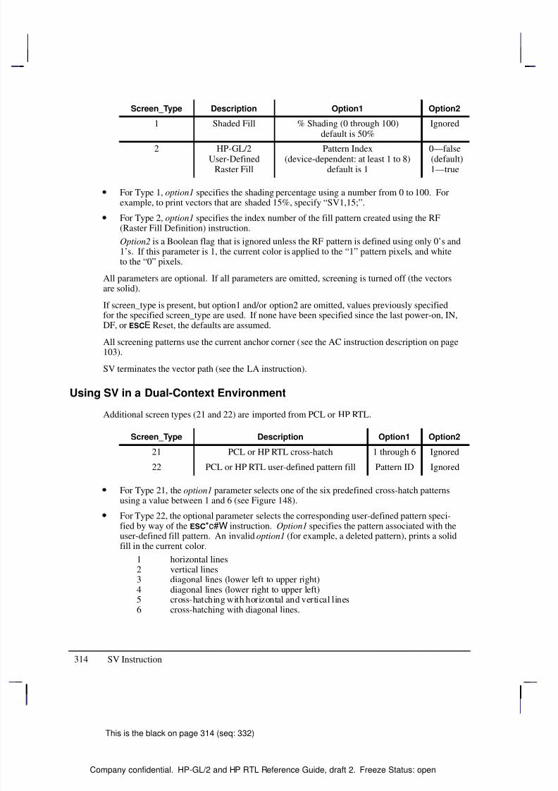
8/12/2019 HPGL2-RTL ReferenceGuide 5961-3526 540pages Sep96
http://slidepdf.com/reader/full/hpgl2-rtl-referenceguide-5961-3526-540pages-sep96 332/539
314
This is the black on page 314 (seq: 332)
Company confidential. HP-GL/2 and HP RTL Reference Guide, draft 2. Freeze Status: open
Screen_Type Description Option1 Option2
1 Shaded Fill % Shading (0 through 100)
default is 50%
Ignored
2 HP-GL/2User-Defined
Raster Fill
Pattern Index(device-dependent: at least 1 to 8)
default is 1
0—false (default)1—true
For Type 1, option1 specifies the shading percentage using a number from 0 to 100. Forexample, to print vectors that are shaded 15%, specify “SV1,15;”.
For Type 2, option1 specifies the index number of the fill pattern created using the RF(Raster Fill Definition) instruction.
Option2 is a Boolean flag that is ignored unless the RF pattern is defined using only 0’s and1’s. If this parameter is 1, the current color is applied to the “1” pattern pixels, and whiteto the “0” pixels.
All parameters are optional. If all parameters are omitted, screening is turned off (the vectorsare solid).
If screen_type is present, but option1 and/or option2 are omitted, values previously specifiedfor the specified screen_type are used. If none have been specified since the last power-on, IN,DF, or E Reset, the defaults are assumed.
All screening patterns use the current anchor corner (see the AC instruction description on page103).
SV terminates the vector path (see the LA instruction).
Using SV in a Dual-Context Environment
Additional screen types (21 and 22) are imported from PCL or HP RTL.
Screen_Type Description Option1 Option2
21 PCL or HP RTL cross-hatch 1 through 6 Ignored
22 PCL or HP RTL user-defined pattern fill Pattern ID Ignored
For Type 21, the option1 parameter selects one of the six predefined cross-hatch patternsusing a value between 1 and 6 (see Figure 148).
For Type 22, the optional parameter selects the corresponding user-defined pattern speci-fied by way of the *c#W instruction. Option1 specifies the pattern associated with theuser-defined fill pattern. An invalid option1 (for example, a deleted pattern), prints a solidfill in the current color.
1 horizontal lines2 vertical lines3 diagonal lines (lower left to upper right)4 diagonal lines (lower right to upper left)5 cross-hatching with horizontal and vertical lines6 cross-hatching with diagonal lines.
SV Instruction
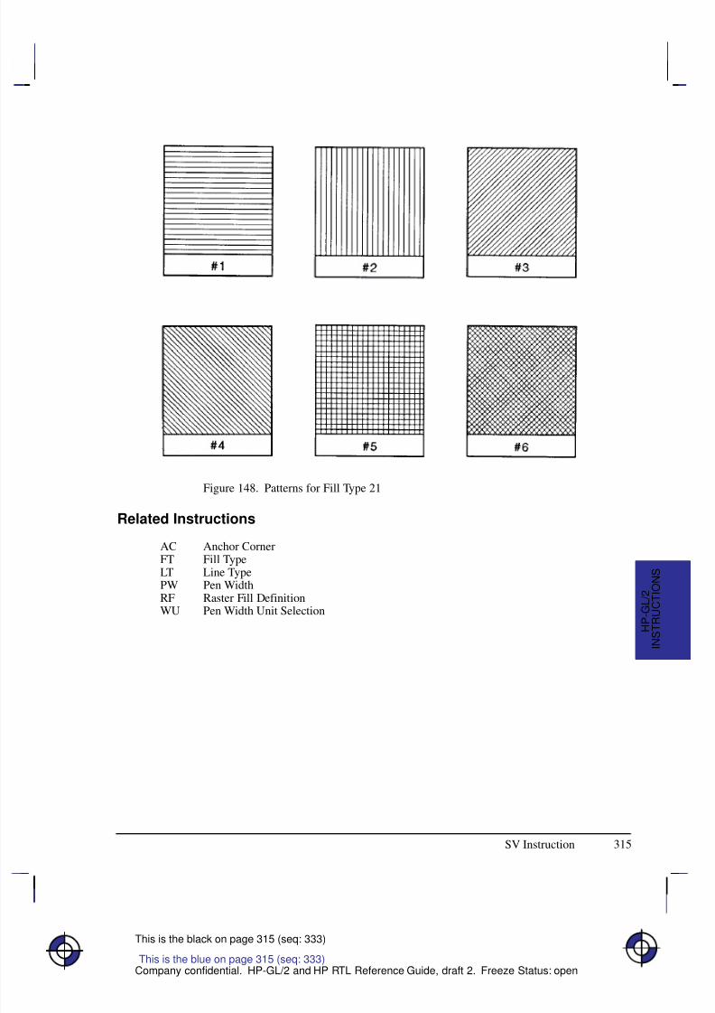
8/12/2019 HPGL2-RTL ReferenceGuide 5961-3526 540pages Sep96
http://slidepdf.com/reader/full/hpgl2-rtl-referenceguide-5961-3526-540pages-sep96 333/539
315
This is the black on page 315 (seq: 333)
Company confidential. HP-GL/2 and HP RTL Reference Guide, draft 2. Freeze Status: open
Figure 148. Patterns for Fill Type 21
Related Instructions
AC Anchor CornerFT Fill TypeLT Line TypePW Pen WidthRF Raster Fill DefinitionWU Pen Width Unit Selection
This is the blue on page 315 (seq: 333)
SV Instruction
I N S T R U C T I O N S
H P - G L / 2
8/12/2019 HPGL2-RTL ReferenceGuide 5961-3526 540pages Sep96
http://slidepdf.com/reader/full/hpgl2-rtl-referenceguide-5961-3526-540pages-sep96 334/539
316
This is the black on page 316 (seq: 334)
Company confidential. HP-GL/2 and HP RTL Reference Guide, draft 2. Freeze Status: open
TD, Transparent Data
Purpose
To specify whether control characters perform their associated control function or print as char-acters when labeling. Use the TD instruction to print characters that function only as controlcharacters in normal mode.
Syntax
TD mode[;]or
TD [;]
Á Á Á Á Á Á Á
Á Á Á Á Á Á Á
Parameter Á Á Á Á Á Á
Á Á Á Á Á Á
Format Á Á Á Á Á Á Á Á
Á Á Á Á Á Á Á Á
Functional Range Á Á Á Á Á Á Á Á
Á Á Á Á Á Á Á Á
Parameter Default
Á Á Á Á Á Á Á
Á Á Á Á Á Á Á
mode Á Á Á Á Á Á
Á Á Á Á Á Á
clamped integerÁ Á Á Á Á Á Á Á
Á Á Á Á Á Á Á Á
0 or 1 Á Á Á Á Á Á Á Á
Á Á Á Á Á Á Á Á
0 (normal)
Group
This instruction is in the Character Group.
Use
The device interprets the parameters as follows:
No Parameters: Defaults the labeling mode to normal. Equivalent to “TD0”.
mode: Selects the normal or transparent data mode for labeling.0 Normal. Control codes with an associated functionality perform their function
and do not print. Control characters with no defined function are ignored. Char-acter codes that are undefined in the current font are printed as spaces. Refer toControl Characters on page 67.
1 Transparent. All characters are printed and perform no other function (except thecurrently defined label terminator, which terminates the label). The device printsa space for non-printing or undefined characters.
Transparent data mode must be enabled to access printable characters which have charactercodes with an associated functionality in normal mode. For example, the left arrow in the PC-8symbol set has a character code of 27. In normal mode, a character code of 27 is interpreted asan escape character (); in transparent data mode, a character code of 27 prints a left arrow.
Using TD in a Dual-Context Environment
Note that in normal mode, E within a label string causes a device reset and transition to thePCL or HP RTL environment. In transparent mode, E within a label string is printed ratherthan performing a device reset.
This is the blue on page 316 (seq: 334)
TD Instruction

8/12/2019 HPGL2-RTL ReferenceGuide 5961-3526 540pages Sep96
http://slidepdf.com/reader/full/hpgl2-rtl-referenceguide-5961-3526-540pages-sep96 335/539
317
This is the black on page 317 (seq: 335)
Company confidential. HP-GL/2 and HP RTL Reference Guide, draft 2. Freeze Status: open
Related Instructions
AD Alternate Font Definition
DT Define Label TerminatorLB LabelSA Select Alternate FontSD Standard Font DefinitionSS Select Standard Font
This is the blue on page 317 (seq: 335)
TD Instruction
I N S T R U C T I O N S
H P - G L / 2
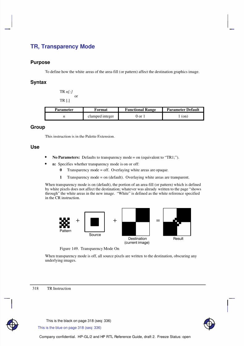
8/12/2019 HPGL2-RTL ReferenceGuide 5961-3526 540pages Sep96
http://slidepdf.com/reader/full/hpgl2-rtl-referenceguide-5961-3526-540pages-sep96 336/539
318
This is the black on page 318 (seq: 336)
Company confidential. HP-GL/2 and HP RTL Reference Guide, draft 2. Freeze Status: open
TR, Transparency Mode
Purpose
To define how the white areas of the area-fill (or pattern) affect the destination graphics image.
Syntax
TR n[;]or
TR [;]
Á Á Á Á Á Á Á
ParameterÁ Á Á Á Á Á
FormatÁ Á Á Á Á Á Á Á
Functional RangeÁ Á Á Á Á Á Á Á
Parameter DefaultÁ Á Á Á Á Á Á
Á Á Á Á Á Á Á
Á Á Á Á Á Á Á
n
Á Á Á Á Á Á
Á
Á Á Á Á Á
Á Á Á Á Á Á
clamped integerÁ Á Á Á Á Á Á Á
Á
Á Á Á Á Á Á Á
Á Á Á Á Á Á Á Á
0 or 1Á Á Á Á Á Á Á Á
Á
Á Á Á Á Á Á Á
Á Á Á Á Á Á Á Á
1 (on)
Group
This instruction is in the Palette Extension.
Use
No Parameters: Defaults to transparency mode = on (equivalent to “TR1;”).
n: Specifies whether transparency mode is on or off:
0 Transparency mode = off. Overlaying white areas are opaque.
1 Transparency mode = on (default). Overlaying white areas are transparent.
When transparency mode is on (default), the portion of an area-fill (or pattern) which is definedby white pixels does not affect the destination; whatever was already written to the page “showsthrough” the white areas in the new image. “White” is defined as the white reference specifiedin the CR instruction.
Figure 149. Transparency Mode On
When transparency mode is off, all source pixels are written to the destination, obscuring anyunderlying images.
This is the blue on page 318 (seq: 336)
TR Instruction
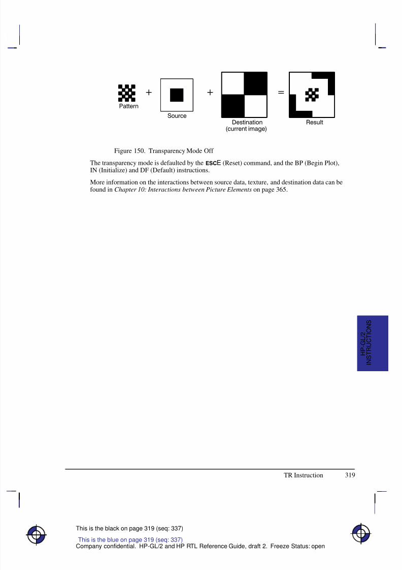
8/12/2019 HPGL2-RTL ReferenceGuide 5961-3526 540pages Sep96
http://slidepdf.com/reader/full/hpgl2-rtl-referenceguide-5961-3526-540pages-sep96 337/539
319
This is the black on page 319 (seq: 337)
Company confidential. HP-GL/2 and HP RTL Reference Guide, draft 2. Freeze Status: open
Figure 150. Transparency Mode Off
The transparency mode is defaulted by the E (Reset) command, and the BP (Begin Plot),IN (Initialize) and DF (Default) instructions.
More information on the interactions between source data, texture, and destination data can befound in Chapter 10: Interactions between Picture Elements on page 365.
This is the blue on page 319 (seq: 337)
TR Instruction
I N S T R U C T I O N S
H P - G L / 2
8/12/2019 HPGL2-RTL ReferenceGuide 5961-3526 540pages Sep96
http://slidepdf.com/reader/full/hpgl2-rtl-referenceguide-5961-3526-540pages-sep96 338/539
320
This is the black on page 320 (seq: 338)
Company confidential. HP-GL/2 and HP RTL Reference Guide, draft 2. Freeze Status: open
UL, User-Defined Line Type
Purpose
To create line types by specifying gap patterns, which define the lengths of spaces and lines thatmake up a line type.
Syntax
UL index [,gap1,...,gapn][;]or
UL [;]
Á Á Á Á Á Á Á
Á Á Á Á Á Á Á
ParameterÁ Á Á Á Á Á
Á Á Á Á Á Á
FormatÁ Á Á Á Á Á Á Á
Á Á Á Á Á Á Á Á
Functional RangeÁ Á Á Á Á Á Á Á
Á Á Á Á Á Á Á Á
Parameter DefaultÁ Á Á Á Á Á Á
Á Á Á Á Á Á Á
Á Á Á Á Á Á Á
index
Á Á Á Á Á Á
Á Á Á Á Á Á
Á Á Á Á Á Á
clamped integer
Á Á Á Á Á Á Á Á
Á Á Á Á Á Á Á Á
Á Á Á Á Á Á Á Á
1 through 8(or –1 through –8)
Á Á Á Á Á Á Á Á
Á Á Á Á Á Á Á Á
Á Á Á Á Á Á Á Á
no default
Á Á Á Á Á Á Á
Á Á Á Á Á Á Á
gap1 to gapnÁ Á Á Á Á Á
Á Á Á Á Á Á
clamped realÁ Á Á Á Á Á Á Á
Á Á Á Á Á Á Á Á
0 to 32767Á Á Á Á Á Á Á Á
Á Á Á Á Á Á Á Á
default line types
Group
This instruction is in the Line and Fill Attributes Group.
Use
The UL command allows you to define and store your own line types. The instruction does notitself select a line type. Use the LT instruction to select the line type once you have defined it
with UL.
No Parameters: Defaults all line types (refer to the LT instruction).
index: Identifies the number of the line type to be redefined. Specifying an index numberwithout gap parameters sets the line type identified by the index to the default pattern forthat number. The index number may not be 0.
The index parameter uses absolute values, so (UL–n) is the same as (ULn). Redefining astandard fixed line type automatically redefines the corresponding adaptive line type.
gap1, ... gapn: Specify alternate pen-down and pen-up stretches in the line type pattern; if gaps are numbered starting with 1, odd numbered gaps are pen-down moves, even num-bered gaps are pen-up moves. The first gap is a pen-down move. Gap values areconverted to percentages of the LT instruction’s pattern_length parameter.
A maximum of 20 gaps are allowed for each user-defined line type. Gap values must benon-negative; a gap value of zero produces a dot if specified for an odd numbered gap thatis preceded or followed by a non-zero even-numbered gap. The sum of the gap parametersmust be greater than zero.
The BP (Begin Plot), IN (Initialize) and DF (Default Values) instructions return user-definedline types to their default patterns.
UL clears the pattern residue and terminates any sequence of continuous vectors (see the LAand LT instructions).
This is the blue on page 320 (seq: 338)
UL Instruction
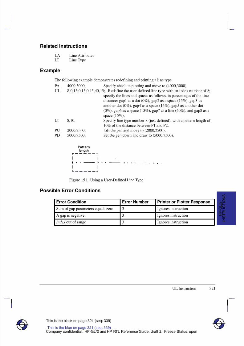
8/12/2019 HPGL2-RTL ReferenceGuide 5961-3526 540pages Sep96
http://slidepdf.com/reader/full/hpgl2-rtl-referenceguide-5961-3526-540pages-sep96 339/539
321
This is the black on page 321 (seq: 339)
Company confidential. HP-GL/2 and HP RTL Reference Guide, draft 2. Freeze Status: open
Related Instructions
LA Line Attributes
LT Line Type
Example
The following example demonstrates redefining and printing a line type.
PA 4000,3000; Specify absolute plotting and move to (4000,3000).
UL 8,0,15,0,15,0,15,40,15; Redefine the user-defined line type with an index number of 8;
specify the lines and spaces as follows, in percentages of the line
distance: gap1 as a dot (0%), gap2 as a space (15%), gap3 as
another dot (0%), gap4 as a space (15%), gap5 as another dot
(0%), gap6 as a space (15%), gap7 as a line (40%), and gap8 as a
space (15%).
LT 8,10; Specify line type number 8 (just defined), with a pattern length of 10% of the distance between P1 and P2.
PU 2000,2500; Lift the pen and move to (2000,2500).
PD 5000,2500; Set the pen down and draw to (5000,2500).
Figure 151. Using a User-Defined Line Type
Possible Error Conditions
Error Condition Error Number Printer or Plotter Response
Sum of gap parameters equals zero 3 Ignores instruction
A gap is negative 3 Ignores instruction
Index out of range 3 Ignores instruction
This is the blue on page 321 (seq: 339)
I N S T R U C T I O N S
H P - G L / 2
UL Instruction
8/12/2019 HPGL2-RTL ReferenceGuide 5961-3526 540pages Sep96
http://slidepdf.com/reader/full/hpgl2-rtl-referenceguide-5961-3526-540pages-sep96 340/539
322
This is the black on page 322 (seq: 340)
Company confidential. HP-GL/2 and HP RTL Reference Guide, draft 2. Freeze Status: open
VS, Velocity Select
Purpose
To specify the pen speed for pen plotters; other devices ignore this instruction. Use VS on penplotters to optimize pen life and line quality for each pen and media combination. Increase linequality and create a slightly thicker line on any media by slowing the pen speed.
Syntax
VS pen_velocity[,pen_number][;]or
VS [;]
Á Á Á Á Á Á Á
Á Á Á Á Á Á Á
Parameter Á Á Á Á Á Á
Á Á Á Á Á Á
Format Á Á Á Á Á Á Á Á
Á Á Á Á Á Á Á Á
Functional Range Á Á Á Á Á Á Á Á
Á Á Á Á Á Á Á Á
Parameter Default
Á Á Á Á Á Á Á
Á Á Á Á Á Á Á
pen_velocity Á Á Á Á Á Á
Á Á Á Á Á Á
clamped integerÁ Á Á Á Á Á Á Á
Á Á Á Á Á Á Á Á
device-dependent * Á Á Á Á Á Á Á Á
Á Á Á Á Á Á Á Á
device-dependent
Á Á Á Á Á Á Á
Á Á Á Á Á Á Á
pen_number Á Á Á Á Á Á
Á Á Á Á Á Á
clamped integerÁ Á Á Á Á Á Á Á
Á Á Á Á Á Á Á Á
device-dependent **Á Á Á Á Á Á Á Á
Á Á Á Á Á Á Á Á
all pens
* Your plotter’s fastest pen velocity may be greater or less than 60 cm/s. Refer to themanual for your plotter for more information.
** Your plotter carousel may handle a different number of pens, or if you are using a ras-ter device, you may have a different number of logical pens that you can use. Refer tothe manual for your plotter or HP-GL/2 option for any additional information.
Group
This instruction is in the Technical Graphics Extension.
Use
Use the VS instruction to increase the pen life and line quality produced by your pens. Slowingthe pen speed increases line quality.
The velocity set by this instruction (or the front panel) determines the maximum velocity corre-sponding to quality level 0 (see QL). As quality level is increased, the plotter will use a lowervelocity, based on the maximum set by VS or the front panel. The default quality level (QL0)should be used when explicit control over velocity is required.
The VS instruction remains in effect until another VS instruction is received or the plotter isinitialized or set to default conditions.
No Parameters: Sets the speed for all pens to the default value. Refer to the manual foryour plotter or HP-GL/2 option for any additional information.
pen_velocity: Specifies the pen speed in centimeters per second (cm/s). You can incre-ment the pen speed by 1 cm/s. If the specified velocity is greater than the plotter’smaximum speed, the maximum speed is used. The selected velocity applies only when thepen is down. The pen-up speed is device-dependent.
This is the blue on page 322 (seq: 340)
VS Instruction
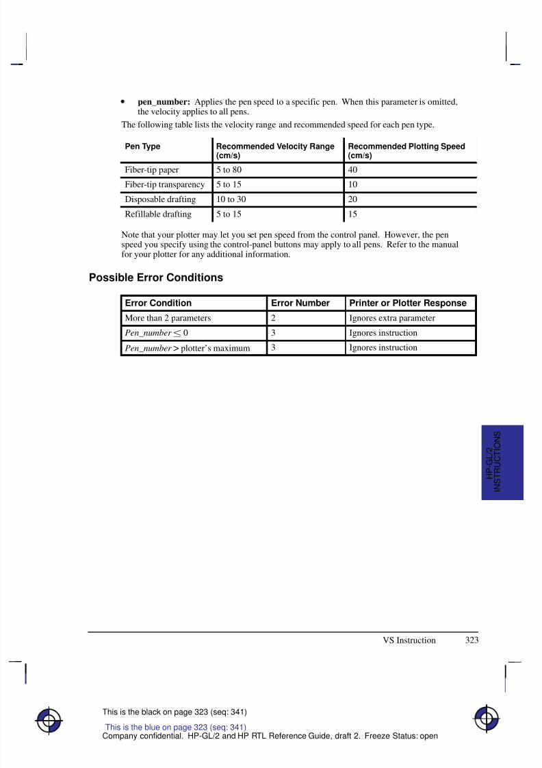
8/12/2019 HPGL2-RTL ReferenceGuide 5961-3526 540pages Sep96
http://slidepdf.com/reader/full/hpgl2-rtl-referenceguide-5961-3526-540pages-sep96 341/539
323
This is the black on page 323 (seq: 341)
Company confidential. HP-GL/2 and HP RTL Reference Guide, draft 2. Freeze Status: open
pen_number: Applies the pen speed to a specific pen. When this parameter is omitted,the velocity applies to all pens.
The following table lists the velocity range and recommended speed for each pen type.
Pen Type Recommended Velocity Range(cm/s)
Recommended Plotting Speed(cm/s)
Fiber-tip paper 5 to 80 40
Fiber-tip transparency 5 to 15 10
Disposable drafting 10 to 30 20
Refillable drafting 5 to 15 15
Note that your plotter may let you set pen speed from the control panel. However, the penspeed you specify using the control-panel buttons may apply to all pens. Refer to the manualfor your plotter for any additional information.
Possible Error Conditions
Error Condition Error Number Printer or Plotter Response
More than 2 parameters 2 Ignores extra parameter
Pen_number 0 3 Ignores instruction
Pen_number > plotter’s maximum 3 Ignores instruction
This is the blue on page 323 (seq: 341)
VS Instruction
I N S T R U C T I O N S
H P - G L / 2
8/12/2019 HPGL2-RTL ReferenceGuide 5961-3526 540pages Sep96
http://slidepdf.com/reader/full/hpgl2-rtl-referenceguide-5961-3526-540pages-sep96 342/539
324
This is the black on page 324 (seq: 342)
Company confidential. HP-GL/2 and HP RTL Reference Guide, draft 2. Freeze Status: open
WG, Fill Wedge
Purpose
To define and fill any wedge. Use WG to draw filled sections of a pie chart.
Syntax
WG radius,start_angle,sweep_angle[,chord_angle][;]
Á Á Á Á Á Á Á
Á Á Á Á Á Á Á
ParameterÁ Á Á Á Á Á
Á Á Á Á Á Á
FormatÁ Á Á Á Á Á Á Á
Á Á Á Á Á Á Á Á
Functional RangeÁ Á Á Á Á Á Á Á
Á Á Á Á Á Á Á Á
Parameter Default
Á Á Á Á Á Á Á
Á Á Á Á Á Á Á
Á Á Á Á Á Á Á
radiusÁ Á Á Á Á Á
Á
Á Á Á Á Á
Á Á Á Á Á Á
current unitsÁ Á Á Á Á Á Á Á
Á
Á Á Á Á Á Á Á
Á Á Á Á Á Á Á Á
device-dependent (at least –223 to 223 – 1)
Á Á Á Á Á Á Á Á
Á
Á Á Á Á Á Á Á
Á Á Á Á Á Á Á Á
no default
Á Á Á Á Á Á Á
Á Á Á Á Á Á Á
start_angleÁ Á Á Á Á Á
Á Á Á Á Á Á
clamped realÁ Á Á Á Á Á Á Á
Á Á Á Á Á Á Á Á
–32768 to 32767Á Á Á Á Á Á Á Á
Á Á Á Á Á Á Á Á
no default
Á Á Á Á Á Á Á
Á Á Á Á Á Á Á
sweep_angle Á Á Á Á Á Á
Á Á Á Á Á Á
clamped real Á Á Á Á Á Á Á Á
Á Á Á Á Á Á Á Á
–360 to +360 Á Á Á Á Á Á Á Á
Á Á Á Á Á Á Á Á
no default
Á Á Á Á Á Á Á
Á Á Á Á Á Á Á
Á Á Á Á Á Á Á
chord_ angle*Á Á Á Á Á Á
Á Á Á Á Á Á
Á Á Á Á Á Á
clamped realÁ Á Á Á Á Á Á Á
Á Á Á Á Á Á Á Á
Á Á Á Á Á Á Á Á
0 to 360Á Á Á Á Á Á Á Á
Á Á Á Á Á Á Á Á
Á Á Á Á Á Á Á Á
device-dependent (usually 5
* If you have used the “CT1” instruction, the chord_angle is interpreted as a deviation dis-tance in current units; see the CT instruction on page 133.
Group
This instruction is in the Polygon Group.
UseThe WG instruction defines and fills a wedge using the current pen, fill type, and line types.The WG instruction includes an automatic pen down. When the instruction operation is com-plete, the original pen location and up/down status are restored.
The only difference between the WG instruction and the EW (Edge Wedge) instruction is thatthe WG instruction produces a filled wedge, and the EW, an outlined one.
WG deletes any stored polygon and stores the wedge in the polygon buffer with an implicitpen-down that overrides any explicit pen-up (PU); therefore the wedge may be subsequentlyre-filled by FP or edged by EP.
If the wedge has more points than will fit in the polygon buffer, the portion of the wedge thatfits in the buffer is closed and filled, and the remainder of the wedge is discarded.
Always use isotropic scaling in any drawing that contains wedges (to avoid drawing an ellipti-cal wedge). (Refer to Scaling on page 24 for more information.)
This is the blue on page 324 (seq: 342)
WG Instruction
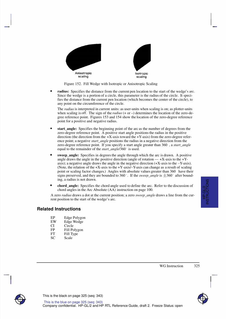
8/12/2019 HPGL2-RTL ReferenceGuide 5961-3526 540pages Sep96
http://slidepdf.com/reader/full/hpgl2-rtl-referenceguide-5961-3526-540pages-sep96 343/539
325
This is the black on page 325 (seq: 343)
Company confidential. HP-GL/2 and HP RTL Reference Guide, draft 2. Freeze Status: open
Figure 152. Fill Wedge with Isotropic or Anisotropic Scaling
radius: Specifies the distance from the current pen location to the start of the wedge’s arc.Since the wedge is a portion of a circle, this parameter is the radius of the circle. It speci-fies the distance from the current pen location (which becomes the center of the circle), toany point on the circumference of the circle.
The radius is interpreted in current units: as user-units when scaling is on; as plotter-unitswhen scaling is off. The sign of the radius (+ or –) determines the location of the zero-de-gree reference point. Figures 153 and 154 show the location of the zero-degree referencepoint for a positive and negative radius.
start_angle: Specifies the beginning point of the arc as the number of degrees from thezero-degree reference point. A positive start angle positions the radius in the positivedirection (the direction from the +X-axis toward the +Y-axis) from the zero-degree refer-ence point; a negative start_angle positions the radius in a negative direction from thezero-degree reference point. If you specify a start angle greater than 360, a start_angleequal to the remainder of the start_angle /360 is used.
sweep_angle: Specifies in degrees the angle through which the arc is drawn. A positiveangle draws the angle in the positive direction (angle of rotation — +X-axis to the +Y-axis); a negative angle draws the angle in the negative direction (+X-axis to the –Y-axis).
(Note, the relation of the +X-axis to the +Y-axis/–Y-axis can change as a result of scalingpoint or scaling factor changes.) Angles with absolute values greater than 360 have theirsigns preserved, and they are bounded to 360. If the sweep_angle is360 after bound-ing, a radius is not drawn.
chord_angle: Specifies the chord angle used to define the arc. Refer to the discussion of chord angles in the Arc Absolute (AA) instruction on page 100.
A zero radius draws a dot at the current position; a zero sweep_angle draws a line from the cur-rent position to the start of the wedge’s arc.
Related Instructions
EP Edge Polygon
EW Edge WedgeCI CircleFP Fill PolygonFT Fill TypeSC Scale
This is the blue on page 325 (seq: 343)
WG Instruction
I N S T R U C T I O N S
H P - G L / 2
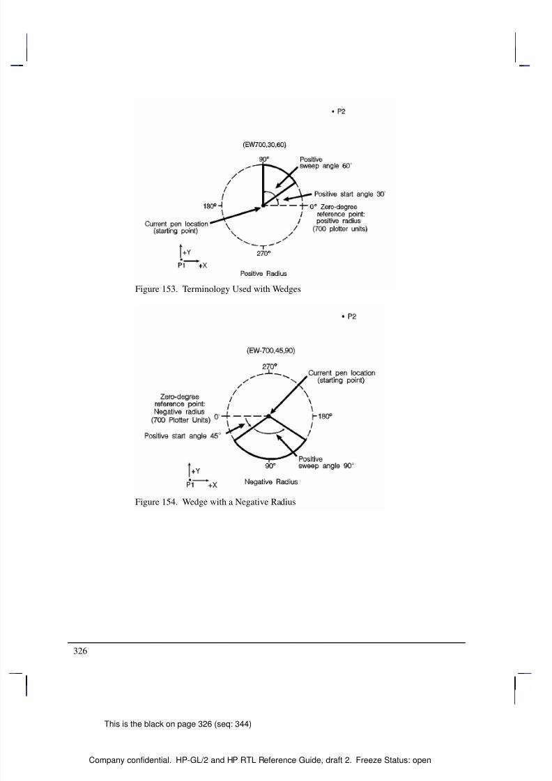
8/12/2019 HPGL2-RTL ReferenceGuide 5961-3526 540pages Sep96
http://slidepdf.com/reader/full/hpgl2-rtl-referenceguide-5961-3526-540pages-sep96 344/539
326
This is the black on page 326 (seq: 344)
Company confidential. HP-GL/2 and HP RTL Reference Guide, draft 2. Freeze Status: open
Figure 153. Terminology Used with Wedges
Figure 154. Wedge with a Negative Radius
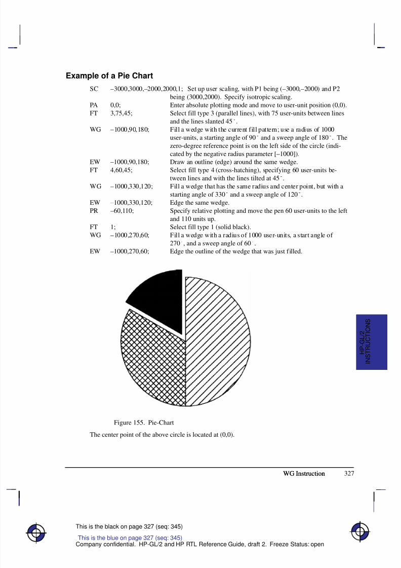
8/12/2019 HPGL2-RTL ReferenceGuide 5961-3526 540pages Sep96
http://slidepdf.com/reader/full/hpgl2-rtl-referenceguide-5961-3526-540pages-sep96 345/539
327
This is the black on page 327 (seq: 345)
Company confidential. HP-GL/2 and HP RTL Reference Guide, draft 2. Freeze Status: open
Example of a Pie Chart
SC –3000,3000,–2000,2000,1; Set up user scaling, with P1 being (–3000,–2000) and P2
being (3000,2000). Specify isotropic scaling.PA 0,0; Enter absolute plotting mode and move to user-unit position (0,0).
FT 3,75,45; Select fill type 3 (parallel lines), with 75 user-units between lines
and the lines slanted 45.
WG –1000,90,180; Fill a wedge with the current fill pattern; use a radius of 1000
user-units, a starting angle of 90 and a sweep angle of 180. The
zero-degree reference point is on the left side of the circle (indi-
cated by the negative radius parameter [–1000]).
EW –1000,90,180; Draw an outline (edge) around the same wedge.
FT 4,60,45; Select fill type 4 (cross-hatching), specifying 60 user-units be-
tween lines and with the lines tilted at 45.
WG –1000,330,120; Fill a wedge that has the same radius and center point, but with a
starting angle of 330 and a sweep angle of 120.
EW –1000,330,120; Edge the same wedge.
PR –60,110; Specify relative plotting and move the pen 60 user-units to the left
and 110 units up.
FT 1; Select fill type 1 (solid black).
WG –1000,270,60; Fill a wedge with a radius of 1000 user-units, a start angle of
270, and a sweep angle of 60.
EW –1000,270,60; Edge the outline of the wedge that was just filled.
Figure 155. Pie-Chart
The center point of the above circle is located at (0,0).
WG Instruction
This is the blue on page 327 (seq: 345)
WG Instruction
I N S T R U C T I O N S
H P - G L / 2
8/12/2019 HPGL2-RTL ReferenceGuide 5961-3526 540pages Sep96
http://slidepdf.com/reader/full/hpgl2-rtl-referenceguide-5961-3526-540pages-sep96 346/539
328
This is the black on page 328 (seq: 346)
Company confidential. HP-GL/2 and HP RTL Reference Guide, draft 2. Freeze Status: open
WU, Pen Width Unit Selection
Purpose
To specify how the width parameter of the PW (Pen Width) instruction is interpreted (whethermetric or relative units).
Syntax
WU type[;]or
WU [;]
Á Á Á Á Á Á Á
Á Á Á Á Á Á Á
ParameterÁ Á Á Á Á Á
Á Á Á Á Á Á
FormatÁ Á Á Á Á Á Á Á
Á Á Á Á Á Á Á Á
Functional RangeÁ Á Á Á Á Á Á Á
Á Á Á Á Á Á Á Á
Parameter DefaultÁ Á Á Á Á Á Á
Á Á Á Á Á Á Á
type
Á Á Á Á Á Á
Á Á Á Á Á Á
clamped integer
Á Á Á Á Á Á Á Á
Á Á Á Á Á Á Á Á
0 or 1
Á Á Á Á Á Á Á Á
Á Á Á Á Á Á Á Á
0 (metric)
Group
This instruction is in the Line and Fill Attributes Group.
Use
Since using WU, with or without parameters, defaults all pen widths, send the WU instructionbefore a PW instruction (which sets a new pen width).
No Parameters: Defaults type parameter to 0 (metric) and all pen widths to 0.35 mm.
type: Specifies how the width parameter of the PW (Pen Width) instruction is interpreted.0 Metric. Interprets the pen width parameter in millimeters.
1 Relative. Interprets the pen width parameter as a percentage of the diagonal dis-tance between P1 and P2.
A WU instruction remains in effect until another WU instruction is executed, or the device isinitialized. WU is not defaulted by the DF (Default Values) instruction.
WU clears the current pattern residue and terminates any continuous vector sequence (see theLA and LT instructions).
Using WU in a PCL Dual-Context Environment
If an HP-GL/2 plot size is specified, metric units are adjusted by the current PCL picture framescaling factor.
Related Instructions
SP Select PenPW Pen Width
This is the blue on page 328 (seq: 346)
WU Instruction

8/12/2019 HPGL2-RTL ReferenceGuide 5961-3526 540pages Sep96
http://slidepdf.com/reader/full/hpgl2-rtl-referenceguide-5961-3526-540pages-sep96 347/539
329
This is the black on page 329 (seq: 347)
Company confidential. HP-GL/2 and HP RTL Reference Guide, draft 2. Freeze Status: open
Possible Error Conditions
Error Condition Error Number Printer or Plotter Response
Type parameter is not 0 or 1 3 Ignores instruction.
This is the blue on page 329 (seq: 347)
WU Instruction
I N S T R U C T I O N S
H P - G L / 2

8/12/2019 HPGL2-RTL ReferenceGuide 5961-3526 540pages Sep96
http://slidepdf.com/reader/full/hpgl2-rtl-referenceguide-5961-3526-540pages-sep96 348/539
330
This is the black on page 330 (seq: 348)
Company confidential. HP-GL/2 and HP RTL Reference Guide, draft 2. Freeze Status: open
8/12/2019 HPGL2-RTL ReferenceGuide 5961-3526 540pages Sep96
http://slidepdf.com/reader/full/hpgl2-rtl-referenceguide-5961-3526-540pages-sep96 349/539
331
This is the black on page 331 (seq: 349)
Company confidential. HP-GL/2 and HP RTL Reference Guide, draft 2. Freeze Status: open
Chapter 6: Summary of HP-GL/2Device-Dependencies
The following HP-GL/2 attributes and parameters are device-dependent; check in the documen-tation for your device for the values and characteristics that it supports.
Functions Supported
Which of the HP-GL/2 Extensions are supported—see Chapter 4: The HP-GL/2 Extensionson page 77.
Whether the following instructions of the Technical Graphics Extension are supported:
– DL (Download Character, page 144)
– EC (Enable Cutter, page 163)
– MG (Message, page 222)
– NR (Not Ready, page 227)any clamping of the timeout parameter of NRthe meaning of “NR;”
– PS (Plot Size, page 259)
– VS (Velocity Select, page 322)the range of supported pen velocities, including the pen-up speed, and thedefault velocity for VS.
Whether the PG (Advance Full Page) instruction of the Configuration and Status Group issupported (see pages 30 and 249).
Whether the RP (Replot) instruction of the Configuration and Status Group is supported(see pages 30 and 279).
– The maximum number of replots supported (see page 279).
– Whether the previous picture is replotted if a picture does not start with a BP (that is, it
began after the last PG or RP), and an RP is issued while still in the picture header (seepage 79).
Function of the BP (Begin Plot) instruction of the Technical Graphics Extension (see pages113—114).
– In a dual-context environment,
– Support of auto-rotation (see the kind 5 parameter of BP),
– Picture name (the kind =1 parameter of BP).
This is the blue on page 331 (seq: 349)
D E V I C E S
H P - G L / 2
8/12/2019 HPGL2-RTL ReferenceGuide 5961-3526 540pages Sep96
http://slidepdf.com/reader/full/hpgl2-rtl-referenceguide-5961-3526-540pages-sep96 350/539
332
This is the black on page 332 (seq: 350)
Company confidential. HP-GL/2 and HP RTL Reference Guide, draft 2. Freeze Status: open
Hardware and System Characteristics
Whether the device is a “printer” or a “plotter” as defined on page 10.Timing of responses to output instructions (see pages 81 and 228).
The default quality level and the range of levels supported for the QL (Quality Level)instruction (see page 267).
The default type parameter of the MT (Media Type) instruction (see page 223).
The range of supported sort algorithms for the ST (Sort) instruction (see page 312).
Coordinate Ranges
The range of internally held coordinates (see page 23).
X and Y parameter coordinate ranges in the following instructions:AA (Arc Absolute, page 100)AC (Anchor Corner, page 103)AR (Arc Relative, page 108)AT (Absolute Arc Three Point, page 110)BR (Bezier Relative, page 116)BZ (Bezier Absolute, page 118)EA (Edge Rectangle Absolute, page 160)ER (Edge Rectangle Relative, page 166)IW (Input Window, page 197)PA (Plot Absolute, page 237)PD (Pen Down, page 241)PE (Polyline Encoded, page 243)
PR (Plot Relative, page 257)PU (Pen Up, page 262)RA (Fill Rectangle Absolute, page 269)RR (Fill Rectangle Relative, page 281)RT (Relative Arc Three Point, page 284)SC (Scale, page 290).
The range of returned X and Y coordinates from the OD (Output Digitized Point and PenStatus) and OP (Output P1 and P2) instructions (see pages 228 and 233).
The range of the number of fractional binary bits in the PE (Polyline Encoded) instruction(see page 243).
Range of radii supported in the CI (Circle), EW (Edge Wedge), and WG (Fill Wedge)instructions (see pages 123, 171, and 324).
The range of values of the length and width parameters of the PS (Plot Size) instruction(see page 259).
Chord Angles
Chord_angle parameter default (usually 5) in the following instructions:AA (Arc Absolute, page 100)AR (Arc Relative, page 108)
This is the blue on page 332 (seq: 350)This is the blue on page 332 (seq: 350)This is the blue on page 332 (seq: 350)
8/12/2019 HPGL2-RTL ReferenceGuide 5961-3526 540pages Sep96
http://slidepdf.com/reader/full/hpgl2-rtl-referenceguide-5961-3526-540pages-sep96 351/539
333
This is the black on page 333 (seq: 351)
Company confidential. HP-GL/2 and HP RTL Reference Guide, draft 2. Freeze Status: open
AT (Absolute Arc Three Point, page 110)CI (Circle, page 123)EW (Edge Wedge, page 171)
RT (Relative Arc Three Point, page 284)WG(Fill Wedge, page 324).
Fill Types and Line Properties
The range of supported fill-types (see page 56).
Edging width in the edge_pen parameter of the CF (Character Fill Mode) instruction (seepage 120).
The range of values of the width parameter of the PW (Pen Width) instruction (see page264).
The range of values of the miter limit attribute of the LA (Line Attributes) instruction (seepage 200).
– The clipping of a line end and line join (see page 200).
– The lower limit below which line ends and line joins always have butt caps and no join.
The supported height s and widths of raster fill patterns in the RF (Raster Fill Definition)instruction (see page 272).
Characters and Fonts
Default label conditions for font spacing, pitch, height, posture, stroke weight, characterwidth and height, and typeface (see pages 65, 106, and 296).
Default scalable font (see page 106).
Character sets and typefaces supported (kinds 1 and 7 of the AD and SD instructions—seepages 106, 296, and 477).
The maximum size of a character (see page 298).
This is the blue on page 333 (seq: 351)
D E V I C E S
H P - G L / 2
This is the blue on page 333 (seq: 351)
8/12/2019 HPGL2-RTL ReferenceGuide 5961-3526 540pages Sep96
http://slidepdf.com/reader/full/hpgl2-rtl-referenceguide-5961-3526-540pages-sep96 352/539
334
This is the black on page 334 (seq: 352)
Company confidential. HP-GL/2 and HP RTL Reference Guide, draft 2. Freeze Status: open
Pens and Colors
The range of supported pens in the following instructions:CF (Character Fill Mode edge_pen parameter, page 120)NP (Number of Pens—the parameter must be a power of 2; the default palette size for
monochrome raster devices is 2, and for color raster devices is 8—page 225)PE (Polyline Encoded following a select-pen flag, page 243)PW (Pen Width pen parameter, page 264)RF (Raster Fill Definition pen_number parameters, page 272)SP (Select Pen pen_number parameter, page 306)VS (Velocity Select, page 322).
In the PC (Pen Color Assignment) instruction, the colors assigned to any pens after the firsteight for a color device, when no parameters are specified (see page 239).
The table look-up algorithm in the device, to determine the merged color, using the MC(Merge Control) instruction (see page 220).
The mapping from colors to gray levels in monochrome devices (see page 239).
Initial Conditions
Language context when the device is powered on (see page 420).
The default conditions set by the DF (Default Values) instruction (see page 136) for thefollowing instruction defaults:
AD (Alternate Font Definition)MT (Media Type)NP (Number of Pens)QL (Quality Level)
SD (Standard Font Definition)ST (Sort)VS (Velocity Select).
This is the blue on page 334 (seq: 352)This is the blue on page 334 (seq: 352)
8/12/2019 HPGL2-RTL ReferenceGuide 5961-3526 540pages Sep96
http://slidepdf.com/reader/full/hpgl2-rtl-referenceguide-5961-3526-540pages-sep96 353/539
335
This is the black on page 335 (seq: 353)
Company confidential. HP-GL/2 and HP RTL Reference Guide, draft 2. Freeze Status: open
PART 3: HP RTL
This Part contains the following sections:
This is the blue on page 335 (seq: 353)
C O N C E P T S
H P R T L
8/12/2019 HPGL2-RTL ReferenceGuide 5961-3526 540pages Sep96
http://slidepdf.com/reader/full/hpgl2-rtl-referenceguide-5961-3526-540pages-sep96 354/539
336
This is the black on page 336 (seq: 354)
Company confidential. HP-GL/2 and HP RTL Reference Guide, draft 2. Freeze Status: open
A list of all the HP RTL commands.
8/12/2019 HPGL2-RTL ReferenceGuide 5961-3526 540pages Sep96
http://slidepdf.com/reader/full/hpgl2-rtl-referenceguide-5961-3526-540pages-sep96 355/539
337
This is the black on page 337 (seq: 355)
Company confidential. HP-GL/2 and HP RTL Reference Guide, draft 2. Freeze Status: open
Chapter 7: HP RTL Concepts
HP RTL is Hewlett-Packard’s Raster Transfer Language. It is a language that is understood byvarious plotters and printers, and is used to produce plotted or printed output from those de-vices. HP RTL is similar to Hewlett-Packard’s PCL printer language; many of its commandsare the same as those of PCL, though some are different, and you should be aware of these dif-ferences if you are already familiar with PCL.
This chapter makes some initial recommendations on writing HP RTL driver programs, anddefines the syntax of HP RTL commands. Not all devices support all commands, or all parame-ter values of commands; check the product-specific documentation for details.
Writing HP RTL Drivers
Writing a raster driver is somewhat simpler than writing a vector driver, since raster driversassume that the data is already in raster format. HP RTL is made up of considerably fewercommands than its companion vector graphics language, HP-GL/2. On the other hand, since araster-format image is closer to a raster device’s native mode of operation than vector output, araster language is by nature more device-dependent than a vector language.
Some users may choose to write a driver to support only one specific device. However, it isassumed that most driver authors will want to write their drivers in such a way that they can beeasily adapted to different HP RTL devices, both present and future. This part of the book
therefore attempts clearly to identify areas of the language that are device-dependent so that theprogrammer can define program variables and organize program procedures accordingly.
Printers and plotters with both HP-GL/2 and HP RTL share a consistent, verified commandimplementation across our product line. In addition, some plotters also include additional ras-ter implementations.
When you are developing an HP RTL driver, consider the following aspects of the support youprovide:
Color and monochrome raster. Some monochrome devices convert color raster data to
shades of gray.
The resolution of your final output. For example, some devices support both 300 and 600
dots per inch (dpi) resolutions.
Plotting “on-the-fly”. Output begins immediately when the first row of raster data isreceived, unlimited raster print or plot sizes can be supported, though queueing and nestingare disabled.
Image storing. Queueing and nesting of output may be supported if the data fits in memory
(limited by the available memory on the device). When memory is full, the device mayautomatically switch to plotting on-the-fly.
Raster data compression to improve throughput.
This is the blue on page 337 (seq: 355)
C O N C E P T S
H P R T L
This is the blue on page 337 (seq: 355)
8/12/2019 HPGL2-RTL ReferenceGuide 5961-3526 540pages Sep96
http://slidepdf.com/reader/full/hpgl2-rtl-referenceguide-5961-3526-540pages-sep96 356/539
338
This is the black on page 338 (seq: 356)
Company confidential. HP-GL/2 and HP RTL Reference Guide, draft 2. Freeze Status: open
You should read Appendix A: Writing Efficient Programs—Some Tips on page 461.
HP RTL Command Syntax
HP RTL is based on Hewlett-Packard’s PCL printer language, and uses the PCL language syn-tax. This section describes HP RTL syntax and explains how you can combine HP RTLcommands. Note that although HP RTL is based on PCL and follows the PCL language syntax,HP RTL does not support the fonts and character commands that are part of PCL. HP RTL isused only to describe raster data. However HP RTL command definition is consistent with thatof PCL, so the transition from one language to the other is quite simple, allowing a wide rangeof HP peripherals to be supported.
HP RTL language commands are compact escape sequence codes that are embedded in the jobdata stream. This approach minimizes both data transmission and command decoding over-head.
Notation for Parameter Formats
You must give parameters in the format required by each HP RTL command. The format of numeric parameters is usually as ASCII characters representing the number. Note that numericranges are minimums; your peripheral may support a larger range. Some values are describedas clamped . This means that if the value is larger than the maximum allowed, the maximum isused; if it is less than the minimum allowed, the minimum is used. Note that the device doesnot recognize exponential format (for example, 6.03E8).
Where binary numbers must be entered into HP RTL commands, they are shown as a decimalvalue in parentheses. For example, the binary number three is denoted by (3), and is encodedin a byte as the binary sequence 00000011. These parentheses must not be encoded.
Other numbers are normally entered as ASCII characters.
Escape Sequences
HP RTL commands are also referred to as escape sequences. Escape sequence commands con-sist of two or more characters. The first character is always the ASCII escape character,identified by the symbol. As the device monitors incoming data from a computer, it is“looking for” the character. When the character appears, the device reads it and itsassociated characters as a command to be performed and not as data to be printed. (An excep-tion is when the character appears in the middle of binary data of a specified length: it isinterpreted as data, not as a command.)
There are two forms of HP RTL escape sequences: two-character escape sequences and para- meterized escape sequences. The only two-character escape sequence used in HP RTL is E
for Reset.
Some escape sequences in this guide contain spaces for clarity. Do not include these spaceswhen using escape sequences (for example, do not leave a space between the and the E of the Reset command). Note that raster commands are case-sensitive: an e, for example,cannot be substituted for an E.
Parameterized escape sequences normally contain a numeric parameter, which is shown in thesyntax descriptions and in many examples by the # character. In all cases, this must be re-
placed by a suitable value.
This is the blue on page 338 (seq: 356)This is the blue on page 338 (seq: 356)
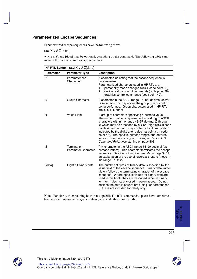
8/12/2019 HPGL2-RTL ReferenceGuide 5961-3526 540pages Sep96
http://slidepdf.com/reader/full/hpgl2-rtl-referenceguide-5961-3526-540pages-sep96 357/539
339
This is the black on page 339 (seq: 357)
Company confidential. HP-GL/2 and HP RTL Reference Guide, draft 2. Freeze Status: open
Parameterized Escape Sequences
Parameterized escape sequences have the following form:
X y # Z [data]
where y, #, and [data] may be optional, depending on the command. The following table sum-marizes the parameterized escape sequences:
HP RTL Syntax: X y # Z[data]
Parameter Parameter Type Description
X ParameterizedCharacter
A character indicating that the escape sequence isparameterized.Parameterized characters used in HP RTL are:% personality mode changes (ASCII code point 37),& device feature control commands (code point 38),* graphics control commands (code point 42).
y Group Character A character in the ASCII range 97–122 decimal (lower-case letters) which specifies the group type of controlbeing performed. Group characters used in HP RTLare a, b, r, t, and v.
# Value Field A group of characters specifying a numeric value.The numeric value is represented as a string of ASCIIcharacters within the range 48–57 decimal (0 through9) which may be preceded by a + or – sign (ASCII codepoints 43 and 45) and may contain a fractional portionindicated by the digits after a decimal point ( . –codepoint 46). The specific numeric ranges and defaultsfor each command are given in Chapter 14: HP RTLCommand Reference starting on page 403.
Z TerminationParameter Character
Any character in the ASCII range 65–90 decimal (up-percase letters). This character terminates the escapesequence. See Combining Commands on page 340 foran explanation of the use of lowercase letters (those inthe range 97–122).
[data] Eight-bit binary data The number of bytes of binary data is specified by thevalue field of the escape sequence. Binary data imme-diately follows the terminating character of the escapesequence. Where specific values for binary data areused in this book, they are described either in binaryform or in decimal enclosed in parentheses. (Do notenclose the data in square brackets [ ] or parentheses(); these are included for clarity only.)
Note: For clarity in explaining how to use specific HP RTL commands, spaces have sometimesbeen inserted; do not leave spaces when you encode these commands.
This is the blue on page 339 (seq: 357)
C O N C E P T S
H P R T L
8/12/2019 HPGL2-RTL ReferenceGuide 5961-3526 540pages Sep96
http://slidepdf.com/reader/full/hpgl2-rtl-referenceguide-5961-3526-540pages-sep96 358/539
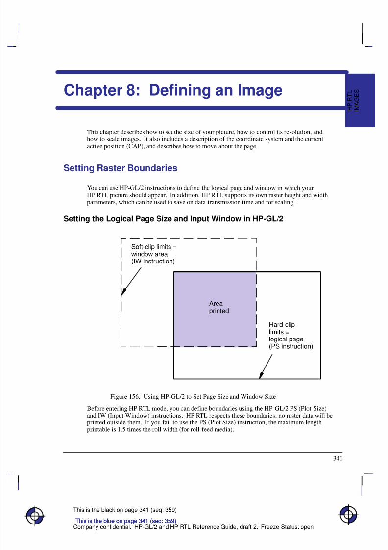
8/12/2019 HPGL2-RTL ReferenceGuide 5961-3526 540pages Sep96
http://slidepdf.com/reader/full/hpgl2-rtl-referenceguide-5961-3526-540pages-sep96 359/539
341
This is the black on page 341 (seq: 359)
Company confidential. HP-GL/2 and HP RTL Reference Guide, draft 2. Freeze Status: open
Chapter 8: Defining an Image
This chapter describes how to set the size of your picture, how to control its resolution, andhow to scale images. It also includes a description of the coordinate system and the currentactive position (CAP), and describes how to move about the page.
Setting Raster Boundaries
You can use HP-GL/2 instructions to define the logical page and window in which yourHP RTL picture should appear. In addition, HP RTL supports its own raster height and widthparameters, which can be used to save on data transmission time and for scaling.
Setting the Logical Page Size and Input Window in HP-GL/2
Areaprinted
Soft-clip limits =window area(IW instruction)
Hard-cliplimits =logical page(PS instruction)
Figure 156. Using HP-GL/2 to Set Page Size and Window Size
Before entering HP RTL mode, you can define boundaries using the HP-GL/2 PS (Plot Size)and IW (Input Window) instructions. HP RTL respects these boundaries; no raster data will beprinted outside them. If you fail to use the PS (Plot Size) instruction, the maximum lengthprintable is 1.5 times the roll width (for roll-feed media).
This is the blue on page 341 (seq: 359)
I M A G E
S
H P R T
L
This is the blue on page 341 (seq: 359)This is the blue on page 341 (seq: 359)
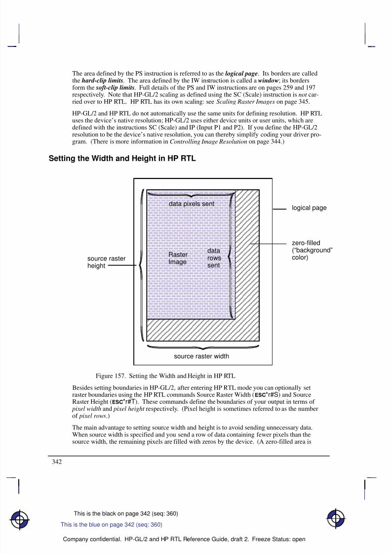
8/12/2019 HPGL2-RTL ReferenceGuide 5961-3526 540pages Sep96
http://slidepdf.com/reader/full/hpgl2-rtl-referenceguide-5961-3526-540pages-sep96 360/539
342
This is the black on page 342 (seq: 360)
Company confidential. HP-GL/2 and HP RTL Reference Guide, draft 2. Freeze Status: open
The area defined by the PS instruction is referred to as the logical page. Its borders are calledthe hard-clip limits. The area defined by the IW instruction is called a window; its bordersform the soft-clip limits. Full details of the PS and IW instructions are on pages 259 and 197
respectively. Note that HP-GL/2 scaling as defined using the SC (Scale) instruction is not car-ried over to HP RTL. HP RTL has its own scaling: see Scaling Raster Images on page 345.
HP-GL/2 and HP RTL do not automatically use the same units for defining resolution. HP RTLuses the device’s native resolution; HP-GL/2 uses either device units or user units, which aredefined with the instructions SC (Scale) and IP (Input P1 and P2). If you define the HP-GL/2resolution to be the device’s native resolution, you can thereby simplify coding your driver pro-gram. (There is more information in Controlling Image Resolution on page 344.)
Setting the Width and Height in HP RTL
logical page
source raster width
source rasterheight
Á Á Á Á Á Á Á Á Á Á
Á Á Á Á Á Á Á Á Á Á
Á Á Á Á Á Á Á Á Á Á
Á Á Á Á Á Á Á Á Á Á
Á Á Á Á Á Á Á Á Á Á
Á Á Á Á Á Á Á Á Á Á
Á Á Á Á Á Á Á Á Á Á
Á Á Á Á Á Á Á Á Á Á
Á Á Á Á Á Á Á Á Á Á
Á Á Á Á Á Á Á Á Á Á
Á Á Á Á Á Á Á Á Á Á
Á Á Á Á Á Á Á Á Á Á
Á Á Á Á Á Á Á Á Á Á
Á Á Á Á Á Á Á Á Á Á
É É É É É É É É É É É É
É É É É É É É É É É É É
É É É É É É É É É É É É
É É É É É É É É É É É É
É É É É É É É É É É É É
É É É É É É É É É É É É
É É É É É É É É É É É É
É É É É É É É É É É É É
É É É É É É É É É É É É
É É É É É É É É É É É É
É É É É É É É É É É É É
É É É É É É É É É É É É
É É É É É É É É É É É É
É É É É É É É É É É É É
É É É É É É É É É É É É
É É É É É É É É É É É É
É É É É É É É É É É É É
zero-filled(“background”color)
data pixels sent
datarowssent
RasterImage
Figure 157. Setting the Width and Height in HP RTL
Besides setting boundaries in HP-GL/2, after entering HP RTL mode you can optionally setraster boundaries using the HP RTL commands Source Raster Width (*r#S) and SourceRaster Height (*r#T). These commands define the boundaries of your output in terms of
pixel width and pixel height respectively. (Pixel height is sometimes referred to as the numberof pixel rows.)
The main advantage to setting source width and height is to avoid sending unnecessary data.When source width is specified and you send a row of data containing fewer pixels than thesource width, the remaining pixels are filled with zeros by the device. (A zero-filled area is
This is the blue on page 342 (seq: 360)
8/12/2019 HPGL2-RTL ReferenceGuide 5961-3526 540pages Sep96
http://slidepdf.com/reader/full/hpgl2-rtl-referenceguide-5961-3526-540pages-sep96 361/539
343
This is the black on page 343 (seq: 361)
Company confidential. HP-GL/2 and HP RTL Reference Guide, draft 2. Freeze Status: open
printed with the color defined for index 0. See Using HP RTL Indexes on page 358.) Similarly,when you send fewer rows of data than specified by source height, the empty rows arezero-filled by the device.
Figure 157 shows an example of zero-filling using source height and width.
When you send a row of pixels that is longer than the source width, the excess pixels are dis-carded; the data is clipped. When you send more rows than specified by source height, theexcess rows are discarded.
It is also possible to set the Destination Raster Width (*t#H) and the Destination RasterHeight (*t#V). When this is done, the source width and height are still used to determinezero-filling and clipping. After zero-filling and clipping, if scale mode is on (that is, the StartRaster Graphics command [*r#A] with a value of 2 or 3 has been used), the image is scaledto the destination width and height. (Note that source width and height must be specified forscaling to work. See Scaling Raster Images on page 345.) Finally, the image is clipped to thesoft-clip and hard-clip limits defined by the HP-GL/2 instructions IW and PS.
The HP RTL raster system uses the concept of a bounded raster picture or raster area. Withinthis area, the device fills missing and incomplete rows with zeros and clips data that would falloutside. This is described more fully in Using Index 0 on page 359.
The raster height extends vertically from the CAP to one of:
The distance specified by Source Raster Height if raster scaling is off
The distance specified by Destination Raster Height if raster scaling is on
The row preceding an implicit or explicit End Raster Graphics command (*rC)
The lower edge of the printable area.
The raster width extends from the left raster margin (the CAP or the left edge of the logicalpage), and is limited to one of:
The distance specified by Source Raster Width if scaling is off
The distance specified by Destination Raster Width if scaling is on
The right edge of the logical page.
Source raster width and height refer to bits of “source” data. One bit of data may result in sev-eral physical pixels if the resolution is set to less than the physical device resolution. SeeControlling Image Resolution on page 344.
Maximum Width and Height
Two factors govern the maximum raster image size:
The device’s physical limits: Physical limits include the maximum picture size (the maxi-
mum number of pixels for height and width), and the amount of data that a device can storein its memory or on its disk. See the device documentation for information on how manypixels the device can handle, and how much memory and/or disk space is available for ras-ter images.
The HP RTL language limits: For all devices, the maximum source width is 65 535 pixels,
and the maximum source height is 65 535 raster rows. Each limit applies only if the corre-
This is the blue on page 343 (seq: 361)
I M A G E
S
H P R T
L
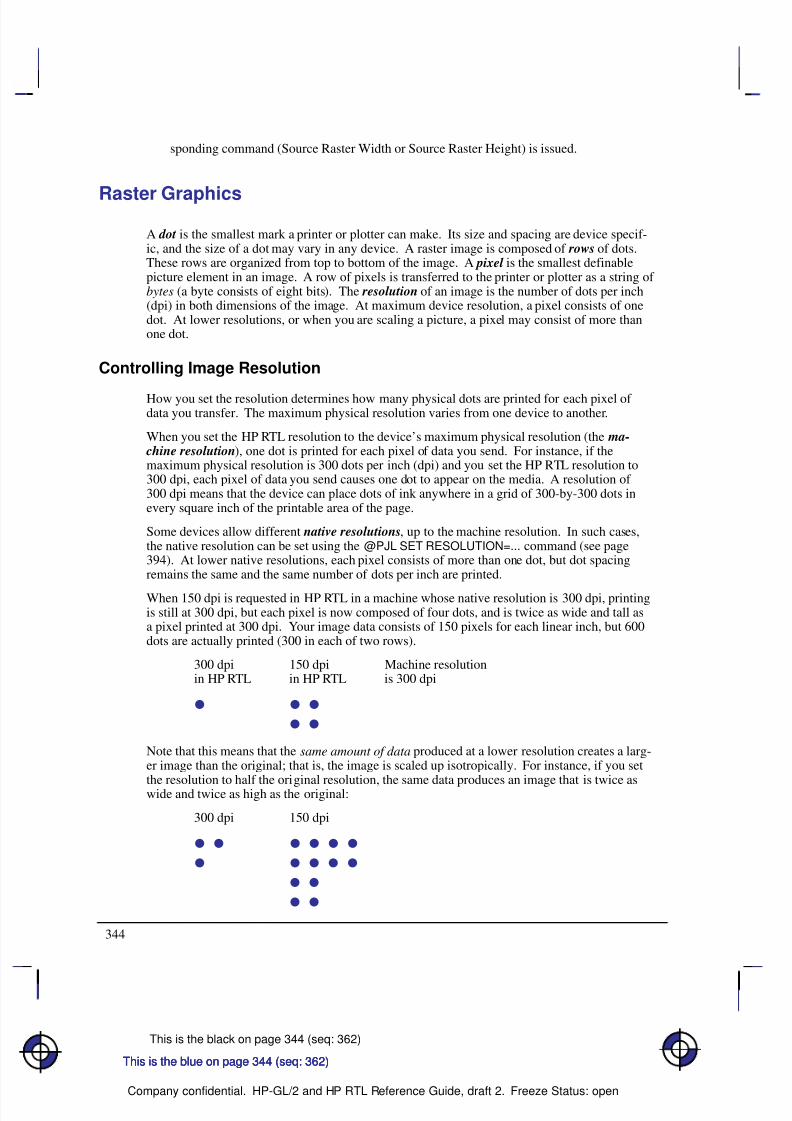
8/12/2019 HPGL2-RTL ReferenceGuide 5961-3526 540pages Sep96
http://slidepdf.com/reader/full/hpgl2-rtl-referenceguide-5961-3526-540pages-sep96 362/539
344
This is the black on page 344 (seq: 362)
Company confidential. HP-GL/2 and HP RTL Reference Guide, draft 2. Freeze Status: open
sponding command (Source Raster Width or Source Raster Height) is issued.
Raster Graphics
A dot is the smallest mark a printer or plotter can make. Its size and spacing are device specif-ic, and the size of a dot may vary in any device. A raster image is composed of rows of dots.These rows are organized from top to bottom of the image. A pixel is the smallest definablepicture element in an image. A row of pixels is transferred to the printer or plotter as a string of bytes (a byte consists of eight bits). The resolution of an image is the number of dots per inch(dpi) in both dimensions of the image. At maximum device resolution, a pixel consists of onedot. At lower resolutions, or when you are scaling a picture, a pixel may consist of more thanone dot.
Controlling Image Resolution
How you set the resolution determines how many physical dots are printed for each pixel of data you transfer. The maximum physical resolution varies from one device to another.
When you set the HP RTL resolution to the device’s maximum physical resolution (the ma- chine resolution), one dot is printed for each pixel of data you send. For instance, if themaximum physical resolution is 300 dots per inch (dpi) and you set the HP RTL resolution to300 dpi, each pixel of data you send causes one dot to appear on the media. A resolution of 300 dpi means that the device can place dots of ink anywhere in a grid of 300-by-300 dots inevery square inch of the printable area of the page.
Some devices allow different native resolutions, up to the machine resolution. In such cases,the native resolution can be set using the @PJL SET RESOLUTION=... command (see page394). At lower native resolutions, each pixel consists of more than one dot, but dot spacingremains the same and the same number of dots per inch are printed.
When 150 dpi is requested in HP RTL in a machine whose native resolution is 300 dpi, printingis still at 300 dpi, but each pixel is now composed of four dots, and is twice as wide and tall asa pixel printed at 300 dpi. Your image data consists of 150 pixels for each linear inch, but 600dots are actually printed (300 in each of two rows).
300 dpi 150 dpi Machine resolutionin HP RTL in HP RTL is 300 dpi
Note that this means that the same amount of data produced at a lower resolution creates a larg-er image than the original; that is, the image is scaled up isotropically. For instance, if you set
the resolution to half the original resolution, the same data produces an image that is twice aswide and twice as high as the original:
300 dpi 150 dpi
This is the blue on page 344 (seq: 362)This is the blue on page 344 (seq: 362)This is the blue on page 344 (seq: 362)
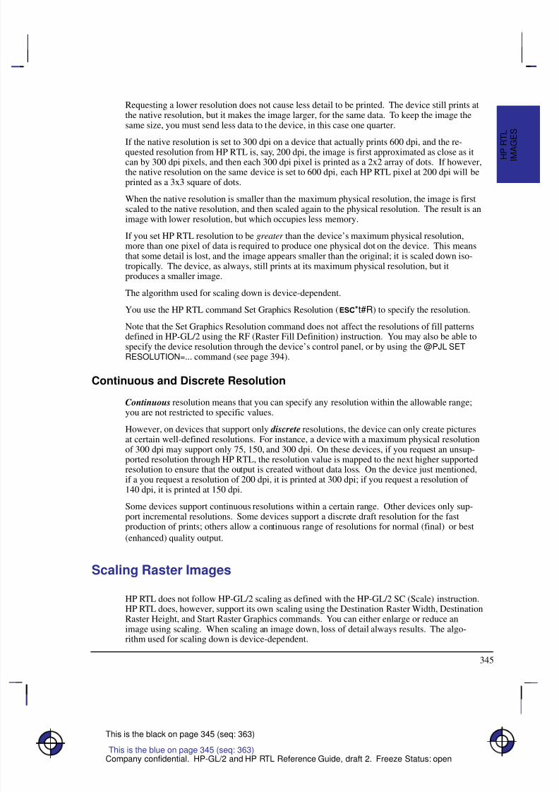
8/12/2019 HPGL2-RTL ReferenceGuide 5961-3526 540pages Sep96
http://slidepdf.com/reader/full/hpgl2-rtl-referenceguide-5961-3526-540pages-sep96 363/539
345
This is the black on page 345 (seq: 363)
Company confidential. HP-GL/2 and HP RTL Reference Guide, draft 2. Freeze Status: open
Requesting a lower resolution does not cause less detail to be printed. The device still prints atthe native resolution, but it makes the image larger, for the same data. To keep the image thesame size, you must send less data to the device, in this case one quarter.
If the native resolution is set to 300 dpi on a device that actually prints 600 dpi, and the re-quested resolution from HP RTL is, say, 200 dpi, the image is first approximated as close as itcan by 300 dpi pixels, and then each 300 dpi pixel is printed as a 2x2 array of dots. If however,the native resolution on the same device is set to 600 dpi, each HP RTL pixel at 200 dpi will beprinted as a 3x3 square of dots.
When the native resolution is smaller than the maximum physical resolution, the image is firstscaled to the native resolution, and then scaled again to the physical resolution. The result is animage with lower resolution, but which occupies less memory.
If you set HP RTL resolution to be greater than the device’s maximum physical resolution,more than one pixel of data is required to produce one physical dot on the device. This meansthat some detail is lost, and the image appears smaller than the original; it is scaled down iso-tropically. The device, as always, still prints at its maximum physical resolution, but it
produces a smaller image.
The algorithm used for scaling down is device-dependent.
You use the HP RTL command Set Graphics Resolution (*t#R) to specify the resolution.
Note that the Set Graphics Resolution command does not affect the resolutions of fill patternsdefined in HP-GL/2 using the RF (Raster Fill Definition) instruction. You may also be able tospecify the device resolution through the device’s control panel, or by using the @PJL SETRESOLUTION=... command (see page 394).
Continuous and Discrete Resolution
Continuous resolution means that you can specify any resolution within the allowable range;
you are not restricted to specific values.However, on devices that support only discrete resolutions, the device can only create picturesat certain well-defined resolutions. For instance, a device with a maximum physical resolutionof 300 dpi may support only 75, 150, and 300 dpi. On these devices, if you request an unsup-ported resolution through HP RTL, the resolution value is mapped to the next higher supportedresolution to ensure that the output is created without data loss. On the device just mentioned,if a you request a resolution of 200 dpi, it is printed at 300 dpi; if you request a resolution of 140 dpi, it is printed at 150 dpi.
Some devices support continuous resolutions within a certain range. Other devices only sup-port incremental resolutions. Some devices support a discrete draft resolution for the fastproduction of prints; others allow a continuous range of resolutions for normal (final) or best
(enhanced) quality output.
Scaling Raster Images
HP RTL does not follow HP-GL/2 scaling as defined with the HP-GL/2 SC (Scale) instruction.HP RTL does, however, support its own scaling using the Destination Raster Width, DestinationRaster Height, and Start Raster Graphics commands. You can either enlarge or reduce animage using scaling. When scaling an image down, loss of detail always results. The algo-rithm used for scaling down is device-dependent.
This is the blue on page 345 (seq: 363)
I M A G E
S
H P R T
L
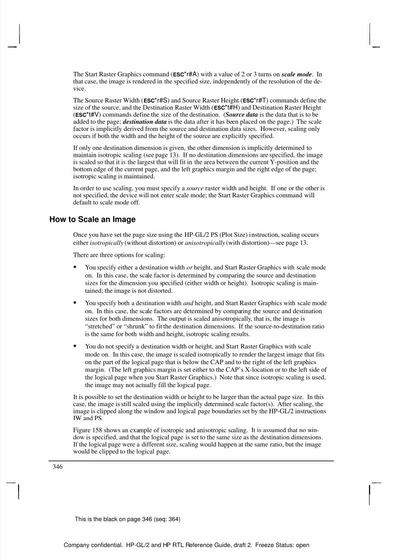
8/12/2019 HPGL2-RTL ReferenceGuide 5961-3526 540pages Sep96
http://slidepdf.com/reader/full/hpgl2-rtl-referenceguide-5961-3526-540pages-sep96 364/539
346
This is the black on page 346 (seq: 364)
Company confidential. HP-GL/2 and HP RTL Reference Guide, draft 2. Freeze Status: open
The Start Raster Graphics command (*r#A) with a value of 2 or 3 turns on scale mode. Inthat case, the image is rendered in the specified size, independently of the resolution of the de-vice.
The Source Raster Width (*r#S) and Source Raster Height (*r#T) commands define thesize of the source, and the Destination Raster Width (*t#H) and Destination Raster Height(*t#V) commands define the size of the destination. (Source data is the data that is to beadded to the page; destination data is the data after it has been placed on the page.) The scalefactor is implicitly derived from the source and destination data sizes. However, scaling onlyoccurs if both the width and the height of the source are explicitly specified.
If only one destination dimension is given, the other dimension is implicitly determined tomaintain isotropic scaling (see page 13). If no destination dimensions are specified, the imageis scaled so that it is the largest that will fit in the area between the current Y-position and thebottom edge of the current page, and the left graphics margin and the right edge of the page;isotropic scaling is maintained.
In order to use scaling, you must specify a source raster width and height. If one or the other is
not specified, the device will not enter scale mode; the Start Raster Graphics command willdefault to scale mode off.
How to Scale an Image
Once you have set the page size using the HP-GL/2 PS (Plot Size) instruction, scaling occurs
either isotropically (without distortion) or anisotropically (with distortion)—see page 13.
There are three options for scaling:
You specify either a destination width or height, and Start Raster Graphics with scale mode
on. In this case, the scale factor is determined by comparing the source and destinationsizes for the dimension you specified (either width or height). Isotropic scaling is main-tained; the image is not distorted.
You specify both a destination width and height, and Start Raster Graphics with scale mode
on. In this case, the scale factors are determined by comparing the source and destinationsizes for both dimensions. The output is scaled anisotropically, that is, the image is“stretched” or “shrunk” to fit the destination dimensions. If the source-to-destination ratiois the same for both width and height, isotropic scaling results.
You do not specify a destination width or height, and Start Raster Graphics with scale
mode on. In this case, the image is scaled isotropically to render the largest image that fitson the part of the logical page that is below the CAP and to the right of the left graphicsmargin. (The left graphics margin is set either to the CAP’s X-location or to the left side of the logical page when you Start Raster Graphics.) Note that since isotropic scaling is used,the image may not actually fill the logical page.
It is possible to set the destination width or height to be larger than the actual page size. In thiscase, the image is still scaled using the implicitly determined scale factor(s). After scaling, theimage is clipped along the window and logical page boundaries set by the HP-GL/2 instructionsIW and PS.
Figure 158 shows an example of isotropic and anisotropic scaling. It is assumed that no win-dow is specified, and that the logical page is set to the same size as the destination dimensions.If the logical page were a different size, scaling would happen at the same ratio, but the imagewould be clipped to the logical page.
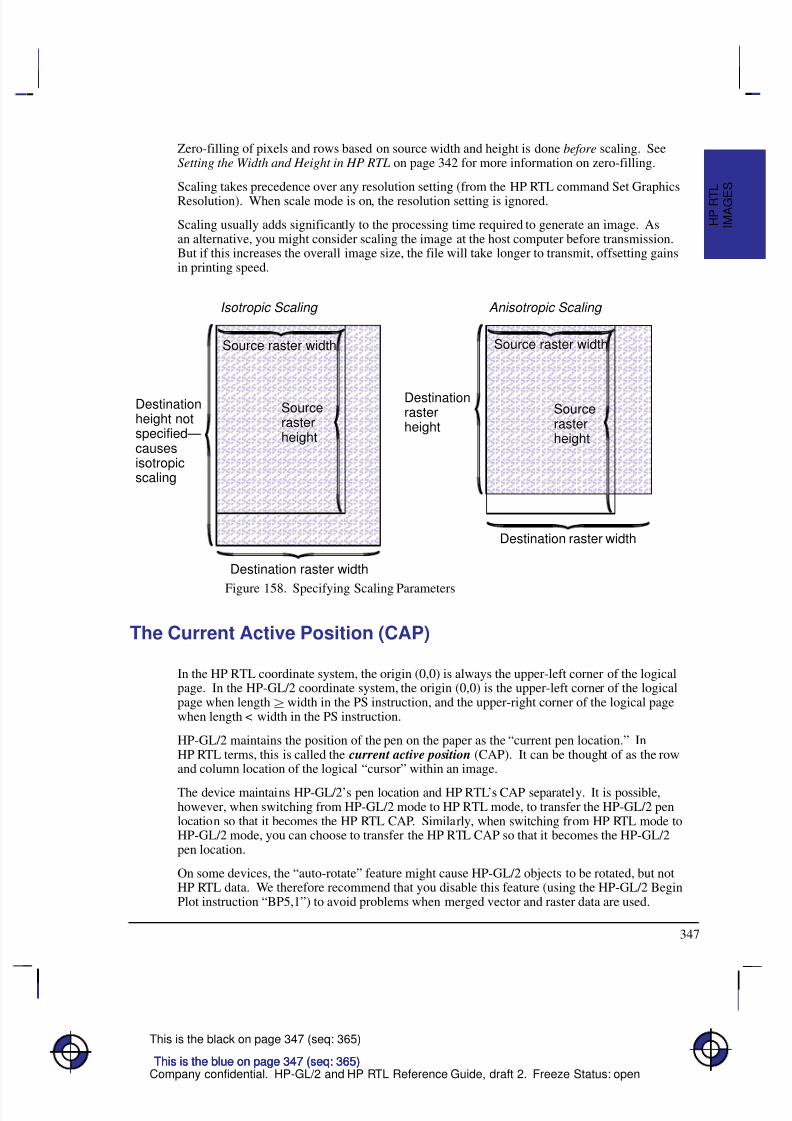
8/12/2019 HPGL2-RTL ReferenceGuide 5961-3526 540pages Sep96
http://slidepdf.com/reader/full/hpgl2-rtl-referenceguide-5961-3526-540pages-sep96 365/539
347
This is the black on page 347 (seq: 365)
Company confidential. HP-GL/2 and HP RTL Reference Guide, draft 2. Freeze Status: open
Zero-filling of pixels and rows based on source width and height is done before scaling. SeeSetting the Width and Height in HP RTL on page 342 for more information on zero-filling.
Scaling takes precedence over any resolution setting (from the HP RTL command Set GraphicsResolution). When scale mode is on, the resolution setting is ignored.
Scaling usually adds significantly to the processing time required to generate an image. Asan alternative, you might consider scaling the image at the host computer before transmission.But if this increases the overall image size, the file will take longer to transmit, offsetting gainsin printing speed.
        Â
        Â
        Â
        Â
        Â
        Â
        Â
        Â
        Â
        Â
        Â
Destination raster width
Destinationheight notspecified—causesisotropicscaling
Source raster width
Sourcerasterheight
Isotropic Scaling
        Â
        Â
        Â
        Â
        Â
        Â
        Â
        Â
        Â
Destination raster width
Destinationrasterheight
Source raster width
Sourcerasterheight
Anisotropic Scaling
Figure 158. Specifying Scaling Parameters
The Current Active Position (CAP)
In the HP RTL coordinate system, the origin (0,0) is always the upper-left corner of the logicalpage. In the HP-GL/2 coordinate system, the origin (0,0) is the upper-left corner of the logicalpage when length width in the PS instruction, and the upper-right corner of the logical pagewhen length < width in the PS instruction.
HP-GL/2 maintains the position of the pen on the paper as the “current pen location.” InHP RTL terms, this is called the current active position (CAP). It can be thought of as the rowand column location of the logical “cursor” within an image.
The device maintains HP-GL/2’s pen location and HP RTL’s CAP separately. It is possible,however, when switching from HP-GL/2 mode to HP RTL mode, to transfer the HP-GL/2 penlocation so that it becomes the HP RTL CAP. Similarly, when switching from HP RTL mode toHP-GL/2 mode, you can choose to transfer the HP RTL CAP so that it becomes the HP-GL/2pen location.
On some devices, the “auto-rotate” feature might cause HP-GL/2 objects to be rotated, but notHP RTL data. We therefore recommend that you disable this feature (using the HP-GL/2 BeginPlot instruction “BP5,1”) to avoid problems when merged vector and raster data are used.
This is the blue on page 347 (seq: 365)This is the blue on page 347 (seq: 365)This is the blue on page 347 (seq: 365)
I M A G E
S
H P R T
L
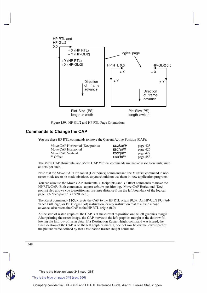
8/12/2019 HPGL2-RTL ReferenceGuide 5961-3526 540pages Sep96
http://slidepdf.com/reader/full/hpgl2-rtl-referenceguide-5961-3526-540pages-sep96 366/539
348
This is the black on page 348 (seq: 366)
Company confidential. HP-GL/2 and HP RTL Reference Guide, draft 2. Freeze Status: open
+ Y (HP RTL)+ X (HP-GL/2)
HP RTL andHP-GL/20,0
HP RTL 0,0 HP-GL/2 0,0
Plot Size (PS)length width
Plot Size (PS)length < width
+ X (HP RTL)+ Y (HP-GL/2)
+ X + X
+ Y + YDirectionof frameadvance
Directionof frameadvance
logical page
Figure 159. HP-GL/2 and HP RTL Page Orientations
Commands to Change the CAP
You use these HP RTL commands to move the Current Active Position (CAP):
Move CAP Horizontal (Decipoints) &a#H page 425Move CAP Horizontal *p#X page 426
Move CAP Vertical *p#Y page 427Y Offset *b#Y page 453.
The Move CAP Horizontal and Move CAP Vertical commands use native resolution units, suchas dots-per-inch.
Note that the Move CAP Horizontal (Decipoints) command and the Y Offset command in non-raster mode are to be made obsolete, so you should not use them in new application programs.
You can also use the Move CAP Horizontal (Decipoints) and Y Offset commands to move theHP RTL CAP. Both commands support relative positioning. Move CAP Horizontal (Deci-points) also allows you to position an absolute distance from the left boundary of the logicalpage. (A “decipoint” is 1/720 inch.)
The Reset command (E) resets the CAP to the HP RTL origin (0,0). An HP-GL/2 PG (Ad-
vance Full Page) or BP (Begin Plot) instruction, or any instruction that results in a pageadvance, also resets the CAP to the HP RTL origin (0,0).
At the start of raster graphics, the CAP is at the current Y-position on the left graphics margin.After printing the raster image, the CAP moves to the left graphics margin at the dot row fol-lowing the last row of raster data. If a Destination Raster Height command was issued, thefinal location of the CAP is on the left graphics margin, one dot row below the lowest part of the picture frame defined by that Destination Raster Height command.
This is the blue on page 348 (seq: 366)
8/12/2019 HPGL2-RTL ReferenceGuide 5961-3526 540pages Sep96
http://slidepdf.com/reader/full/hpgl2-rtl-referenceguide-5961-3526-540pages-sep96 367/539
349
This is the black on page 349 (seq: 367)
Company confidential. HP-GL/2 and HP RTL Reference Guide, draft 2. Freeze Status: open
Negative Motion
It can be important when you are printing or plotting an image for the device to know whether
there might be any movement of the CAP in a direction opposite to the movement of paper.This is known as negative motion. Negative motion is:
Any HP-GL/2 drawing operation.
Any operation that would print in the negative Y-axis direction with respect to previously
printed data.
Any Y Offset command in raster mode that moves the CAP in the negative Y-axis direc-
tion.
You use this HP RTL command to tell the device whether to expect negative motion:
Negative Motion &a#N page 428.
You tell the device you are not using negative motion using the Negative Motion command
with a value of 1 (
&a1N), the device may interleave parsing of data and printing, to reducethe printing time and to reduce the memory requirements. Printing on the device is not guaran-teed if a command is later issued that might cause negative motion to take place.
HP RTL Native Resolution Units
CAP movement should normally be performed at HP RTL native resolution. The native resolu-tion is usually a sub-multiple of the physical device resolution, which is the number of dots perinch that the device can print. HP RTL native resolutions are device-dependent. On devicesthat support several native resolutions, the native resolution can be selected by the command:
@PJL SET RESOLUTION=# page 394.
The native resolution is used in HP RTL for two purposes:
To select the resolution for CAP movements.
To select the resolution to which the raster image is to be scaled. Selecting a smaller reso-
lution than the device’s maximum physical resolution uses less memory but does notexploit the detail that the device can provide. Lower resolutions are therefore recom-mended when you produce drafts, and not for final production runs.
This is the blue on page 349 (seq: 367)
I M A G E
S
H P R T
L

8/12/2019 HPGL2-RTL ReferenceGuide 5961-3526 540pages Sep96
http://slidepdf.com/reader/full/hpgl2-rtl-referenceguide-5961-3526-540pages-sep96 368/539
350
This is the black on page 350 (seq: 368)
Company confidential. HP-GL/2 and HP RTL Reference Guide, draft 2. Freeze Status: open
8/12/2019 HPGL2-RTL ReferenceGuide 5961-3526 540pages Sep96
http://slidepdf.com/reader/full/hpgl2-rtl-referenceguide-5961-3526-540pages-sep96 369/539
351
This is the black on page 351 (seq: 369)
Company confidential. HP-GL/2 and HP RTL Reference Guide, draft 2. Freeze Status: open
Chapter 9: Defining Colors
This chapter describes how to define colors and how to select colors from a palette. It also de-scribes halftoning and how to use patterns.
Palettes
A palette is a collection of colors, in which the color is selected by an index number. AllHP RTL color modes have default palettes. Only one palette can be active at a time, though
you can push palettes onto a stack and pop them from the stack. The active palette is overwrit-ten whenever a new palette is created or a palette is popped from the stack. The active paletteis always transferred between HP RTL and HP-GL/2 on devices that support palettes inHP RTL.
The figure below illustrates a palette. Each palette entry associates an index number with threeprimary color components; for HP-GL/2 only, a “pen width” is also associated with each entry.
Primary 1(e.g. red)
Primary 2(green)
Primary 3(blue)
HP-GL/2pen width
Index 0 Pixel encoding mode
1 Pixel or Plane
2 Direct or Indirect
3
4 Bits per primary
5 Primary 1 (red)
6 Primary 2 (green)
n(maximum
255)
Primary 3 (blue)
Palettes are used differently depending on whether the device is in raster mode or not: in non-raster mode, the palette is always needed to select colors; in raster mode, the palette is usedonly for indexed color selection, but not for direct selection.
Raster Color and Non-Raster Color
Raster mode (see Transferring Raster Data on page 375) is normally entered by a Start RasterGraphics (*r#A) command and ended by an End Raster Graphics (*rC) command. Innon-raster mode, the palette is always used to select colors; the color of a pattern is specifiedusing the Foreground Color (*v#S) command. In raster mode, the palette is only used forindexed color selection, and not for direct color selection.
This is the blue on page 351 (seq: 369)
C O L O R S
H P R T L
This is the blue on page 351 (seq: 369)
C O L O R S
H P R T L
8/12/2019 HPGL2-RTL ReferenceGuide 5961-3526 540pages Sep96
http://slidepdf.com/reader/full/hpgl2-rtl-referenceguide-5961-3526-540pages-sep96 370/539
8/12/2019 HPGL2-RTL ReferenceGuide 5961-3526 540pages Sep96
http://slidepdf.com/reader/full/hpgl2-rtl-referenceguide-5961-3526-540pages-sep96 371/539
353
This is the black on page 353 (seq: 371)
Company confidential. HP-GL/2 and HP RTL Reference Guide, draft 2. Freeze Status: open
The black and white references specified by the Configure Image Data command have no effecton the default palettes; however if a palette entry is reprogrammed with a different color, theblack and white references are used to specify the primary components of the new color.
HP-GL/2 Imaging Mode
In HP-GL/2, the IN (Initialize) and BP (Begin Plot) commands start color imaging and alsodefault the number of bits per index, and create a default programmable palette. This palettecan be modified in HP RTL or in HP-GL/2. (The active palette can be transferred betweenHP RTL and HP-GL/2.)
As shown below, the default HP-GL/2 palettes are different from the default HP RTL palettes.These palettes can be modified in the same way as the default HP RTL palettes.
Number of Pens Pen Number Color
Specifying Colors
Colors can be specified by either indexed or direct selection. If you are using simple colormode or black-and-white mode, only indexed selection is available. Otherwise, byte #1 of theConfigure Image Data command (*v#W) determines the format in which raster data is to betransmitted and interpreted.
Raster colors—colors that are specified in raster transfer mode—can be selected directly orindirectly, depending on the meaning of the bits that are transferred; that is, the transmitted bit
combinations for each pixel may form a palette index number or they may directly specifycomponent proportions.
Non-raster colors—for example, foreground colors or multi-colored patterns—cannot be se-lected directly.
This is the blue on page 353 (seq: 371)
C O L O R S
H P R T L
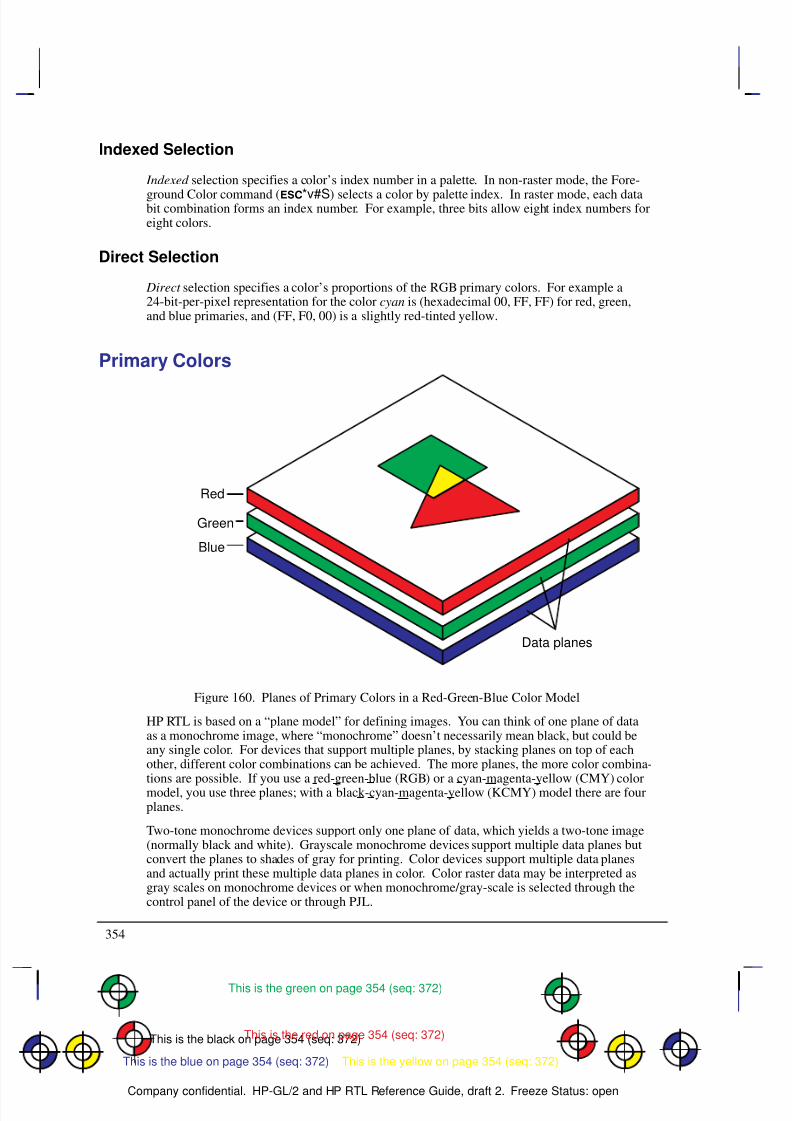
8/12/2019 HPGL2-RTL ReferenceGuide 5961-3526 540pages Sep96
http://slidepdf.com/reader/full/hpgl2-rtl-referenceguide-5961-3526-540pages-sep96 372/539
354
This is the black on page 354 (seq: 372)
Company confidential. HP-GL/2 and HP RTL Reference Guide, draft 2. Freeze Status: open
Indexed Selection
Indexed selection specifies a color’s index number in a palette. In non-raster mode, the Fore-
ground Color command (*v#S) selects a color by palette index. In raster mode, each databit combination forms an index number. For example, three bits allow eight index numbers foreight colors.
Direct Selection
Direct selection specifies a color’s proportions of the RGB primary colors. For example a24-bit-per-pixel representation for the color cyan is (hexadecimal 00, FF, FF) for red, green,and blue primaries, and (FF, F0, 00) is a slightly red-tinted yellow.
Primary Colors
Red
Green
Blue
Data planes
Figure 160. Planes of Primary Colors in a Red-Green-Blue Color Model
HP RTL is based on a “plane model” for defining images. You can think of one plane of dataas a monochrome image, where “monochrome” doesn’t necessarily mean black, but could beany single color. For devices that support multiple planes, by stacking planes on top of eachother, different color combinations can be achieved. The more planes, the more color combina-tions are possible. If you use a red-green-blue (RGB) or a cyan-magenta-yellow (CMY) colormodel, you use three planes; with a black-cyan-magenta-yellow (KCMY) model there are fourplanes.
Two-tone monochrome devices support only one plane of data, which yields a two-tone image(normally black and white). Grayscale monochrome devices support multiple data planes butconvert the planes to shades of gray for printing. Color devices support multiple data planesand actually print these multiple data planes in color. Color raster data may be interpreted asgray scales on monochrome devices or when monochrome/gray-scale is selected through thecontrol panel of the device or through PJL.
This is the red on page 354 (seq: 372)
This is the yellow on page 354 (seq: 372)
This is the green on page 354 (seq: 372)
This is the blue on page 354 (seq: 372)
8/12/2019 HPGL2-RTL ReferenceGuide 5961-3526 540pages Sep96
http://slidepdf.com/reader/full/hpgl2-rtl-referenceguide-5961-3526-540pages-sep96 373/539
355
This is the black on page 355 (seq: 373)
Company confidential. HP-GL/2 and HP RTL Reference Guide, draft 2. Freeze Status: open
Color specifications are based on a range of values for each primary component. The basis of these specifications is device-dependent. The end-points of the range for each component arecalled the black and white references for that component. Colors relative to these predefined
limits are derived by specifying the amount of each component.Assume, for instance, that you define one plane of data to be red, another green, and anotherblue. (These are, in fact, the recommended definitions for three-plane devices.) By layingthese images on top of each other, up to eight colors can be achieved in any given pixel. Allthree together in one pixel gives white. Solid red and green together give yellow; green andblue together give cyan; and so on, following the standard red-green-blue (RGB) color model.
Black and White References
For RGB color spaces, the black-reference for a primary color denotes a value assigned to theabsence of that color, and the white-reference denotes the value given to a fully saturated pri-mary color. Regardless of the number chosen, the white reference represents the maximumamount of output color that the device can produce, and the black reference is the minimum
amount of that primary. For example, if you define the white reference for the color red to be100, this number represents the reddest red that the device can produce. If you specified 10 asthe white reference for red, 10 would represent the same red.
For example, if the red, green, and blue white references are set to 64 and the black referencesare all 0, a 50% blue would be represented by the numbers 0, 0, 32, and a 50% yellow would be32, 32, 0.
But if the white references are set to 64, 128, and 32 respectively, and the black references areset to 4, 0, 0, the 50% blue is 4, 0, 16 and the 50% yellow is 34, 64, 0.
However, for all practical purposes, the following values are recommended for each primarycolor: for an RGB color model use a white reference of 255 and a black reference of 0; for aCMY color model, use a white reference of 0 and a black reference of 255.
Color-Definition Commands
You use these commands to define how the device handles color data:
Configure Image Data *v#W[data] page 409Set Red Parameter *v#A page 442Set Green Parameter *v#B page 441Set Blue Parameter *v#C page 439Assign Color Index *v#I page 407Push/Pop Palette *p#P page 434Simple Color *r#U page 443.
If you are using the HP RTL command Configure Image Data to specify re-programmable pal-ettes, for pixel encoding modes 0, 1, or 4, you use the Set Number of Bits per Index byte of thiscommand to tell the device how many data planes to expect. This command also resets theHP RTL palette to its default—see Defining the HP RTL Palette on page 356.
You can combine different images with different numbers of planes on the same page. For in-stance, you could have a three-plane color image and one-plane monochrome image on thesame page.
The Simple Color command should be used to specify CMY or KCMY data.
C O L O R S
H P R T L
This is the blue on page 355 (seq: 373)
8/12/2019 HPGL2-RTL ReferenceGuide 5961-3526 540pages Sep96
http://slidepdf.com/reader/full/hpgl2-rtl-referenceguide-5961-3526-540pages-sep96 374/539
356
This is the black on page 356 (seq: 374)
Company confidential. HP-GL/2 and HP RTL Reference Guide, draft 2. Freeze Status: open
Encoding Colors
Several bits per pixel are required to produce multiple colors. For HP RTL Imaging Mode, you
use byte #1 of the Configure Image Data command (*v#W) to select the method. The bitsthat define pixels may be encoded by plane, by pixel , or in plane-by-plane format.
Encoding by Plane
When colors are encoded by plane, each pixel in a row receives one bit (plane), then everypixel receives the next plane, until the pixels in a row are completely defined. That is, all thepixels in a row are partially defined by each plane until the last plane for that row is sent. Thenumber of planes is the number of bits needed to define (color) a pixel. In the following exam-ple, the highlighted bits comprise the color index for the third pixel in the first row.
*b#V row 1 plane 1 b1 b1 b1 b1 b1 b1 ...
*b#V plane 2 b2 b2 b2 b2 b2 b2 ...
*b#W plane 3 b3 b3 b3 b3 b3 b3 ...
*b#V row 2 plane 1 b1 b1 b1 b1 b1 b1 ...
Encoding by Pixel
When colors are encoded by pixel, all the bits for a pixel are sent as a group (for example,24-bit RGB), then all the bits for the next pixel until the pixels in a row are defined. Each pixelreceives all its bits before any bits are sent for the next pixel. Byte boundaries are ignored,with the bits for successive pixels following one another. For example, if four bits are neededto define a pixel, then every group of four bits in the data stream defines a pixel. The high-lighted group below defines the second pixel in the first row.
*b#W row 1 b4 b3 b2 b1 c4 c3 c2 c1 ...
*b#W row 2 b4 b3 b2 b1 ...
The HP RTL options for selecting colors and encoding raster data are:
Planar Encoding Pixel Encoding
Indexed Selection Indexed planar Indexed pixel
Direct Selection Direct planar Direct pixel
Encoding Plane-by-Plane
Another way of sending a color image to a device is by decomposing the entire image into sep-arate color planes. This is typically done using the device’s primary colors (for example, black,cyan, magenta, and yellow), and an entire image is sent for each primary color. The Y Offsetcommand (*b#Y) is used to regain the starting position so that the planes can be overlaid asintended.
Defining the HP RTL Palette
HP RTL maintains an internal palette from which you can choose colors for each pixel of data.
For indexed selection, the size of the color palette depends on the number of planes being used:for one plane, there are two possible colors; for two planes, there are four possible colors; for
This is the blue on page 356 (seq: 374)
8/12/2019 HPGL2-RTL ReferenceGuide 5961-3526 540pages Sep96
http://slidepdf.com/reader/full/hpgl2-rtl-referenceguide-5961-3526-540pages-sep96 375/539
357
This is the black on page 357 (seq: 375)
Company confidential. HP-GL/2 and HP RTL Reference Guide, draft 2. Freeze Status: open
three planes, there are eight possible colors; and so on. HP RTL allows for up to eight dataplanes or 256 possible colors. The maximum number of planes, and thus the maximum palettesize, is device-dependent.
In indexed mode, data sent to the device uses the index number to choose a color for each pixel.See Using HP RTL Indexes on page 358.
In direct pixel encoding mode, the palette is not used.
Note that the HP RTL palette on some devices is independent of the HP-GL/2 palette. On thesedevices, palettes cannot be automatically transferred between HP-GL/2 and HP RTL. See thedescriptions of the Enter RTL Mode and Enter HP-GL/2 Mode commands in Chapter 14 formore information on transferring palettes.
Changing the Default Palette
Creating a new palette overwrites the old one. The Push/Pop Palette command (*p#P) cansave (push) the current palette and then restore (pop) it. Palette entries can be modified in HP-GL/2 by the CR (Set Color Range for Relative Color Data), NP (Number of Pens), and PC (PenColor Assignment) instructions, or by the HP RTL commands Set Red/Green/Blue Parameter(*v#A, *v#B, and *v#C) and Assign Color Index (*v#I).
When you switch from HP RTL to HP-GL/2 or vice versa, the palette is transferred. So anychanges made in one environment are automatically transferred to the other. As a result, if youwant to use separate palettes in the different environments, you must use the Push/Pop Palettecommand.
You can use a combination of commands to change the HP RTL palette defaults to any color.For instance, to set index 5 to a 50% blue, you use the following combined HP RTL command:
*v0a0b127c5I
The commands combined here are Set Red Parameter, Set Green Parameter, Set Blue Parame-
ter, and Assign Color Index. Note that 127 is halfway (50%) between 0 and 255, the defaultrange for the Set Red/Green/Blue Parameter commands.
A “50%” blue may not appear the same on all devices. Differences in imaging technology, me-dia, imaging agent (ink or toner, for example), and environmental conditions can cause colordifferences among devices. These differences are subject to program control, but their cover-age is beyond the scope of this book.
You can assign any color supported by a device to an index. On some devices, non-primarycolors are printed using a dithering technique, as in HP-GL/2 mode. (Primary colors are thosecolors that a device can create by printing zero, one, or two ink or toner colors together, usuallyred, green, blue, magenta, cyan, yellow, black, and white.)
Changing the Black and White References
By default, the RGB value for black is 0,0,0, and the value for white is 255,255,255. You canchange these white and black references using the HP RTL command Configure Image Data.For instance, if you work in percentages, you could use the following command to set theranges to 0 to 100:
*v18W(0)(0)(3)(8)(8)(8)(100)(100)(100)(0)(0)(0)
The last six numbers set the white references for red, green, and blue, and then the correspond-ing black references. (For clarity, numbers in the data string are shown in decimal, enclosed in
This is the blue on page 357 (seq: 375)
C O L O R S
H P R T L
8/12/2019 HPGL2-RTL ReferenceGuide 5961-3526 540pages Sep96
http://slidepdf.com/reader/full/hpgl2-rtl-referenceguide-5961-3526-540pages-sep96 376/539
358
This is the black on page 358 (seq: 376)
Company confidential. HP-GL/2 and HP RTL Reference Guide, draft 2. Freeze Status: open
parentheses. In practice, they must be transmitted as binary numbers, without parentheses; thefirst six are one-byte values, the second six are two bytes each. See page 409 for more in-formation on the Configure Image Data command; the example on page 360 shows a similar
command to that just described, but using different white reference values.)Now, to set index 5 to 50% blue using the white and black references just defined, use the fol-lowing combined command:
*v0a0b50c5I
Using HP RTL Indexes
When you send data to the device, you send it one row at a time. Assuming you are sendingsingle-plane data, you send all the data for the first row, then all the data for the second row,and so on.
For example, the loop in a sample program might look like this:for n := 1 to number_of_rows do
for m := 1 to width_in_pixels do
send one pixel (one bit) of data;
You can think of the color palette as an array in a programming language. The color of eachpixel is determined by “indexing into” the color palette using the bit value (0 or 1) as the sub-script. A “0” pixel accesses the color assigned to index 0 (by default, white); a “1” pixelaccesses the color assigned to index 1 (by default, black).
For instance, assume you sent the following data to the device:
0 1 0 1 1 1 1 1 0 0 0 0 1 1 1 1
Based on the HP RTL default palette, the first pixel would be white, the second black, the third
white, and so on.
Multi-Plane Data
As with single-plane data, you send multi-plane data one row at a time. However, with multi-plane data, you send all the planes for each row together—all the planes for the first row, thenall the planes for the second row, and so on. (Even in block transfers, the order of the data re-mains the same. Block transfers are explained under Compressing Data on page 380.)
For example, if you have three planes of data, the loop in a sample program might look likethis:
for n := 1 to number_of_rows do
begin
send one row of data for first plane;send one row of data for second plane;
send one row of data for third plane;
end;
(“Send one row of data” implies a loop to send each row a pixel at a time, as shown in the sing-le-plane example above.)
This is the blue on page 358 (seq: 376)
8/12/2019 HPGL2-RTL ReferenceGuide 5961-3526 540pages Sep96
http://slidepdf.com/reader/full/hpgl2-rtl-referenceguide-5961-3526-540pages-sep96 377/539
8/12/2019 HPGL2-RTL ReferenceGuide 5961-3526 540pages Sep96
http://slidepdf.com/reader/full/hpgl2-rtl-referenceguide-5961-3526-540pages-sep96 378/539
360
This is the black on page 360 (seq: 378)
Company confidential. HP-GL/2 and HP RTL Reference Guide, draft 2. Freeze Status: open
Example: Programming the Color Palette
First the Configure Image Data command (
*v18W[data]) is sent, where [data] is:Byte # Binary data Decimal value Effect
0 00000000 0 Color space device-dependent RGB
1 00000000 0 Pixel encoding mode is indexed by plane
2 00000011 3 3 bits per index
3 00001000 8 8 bits for red
4 00001000 8 8 bits for green
5 00001000 8 8 bits for blue
6, 7 0000000011111111 255 White reference for red is 255
8, 9 0000000011111111 255 White reference for green is 255
10, 11 0000000001111111 127 White reference for blue is 127
12, 13 0000000000000000 0 Black reference for red is 0
14, 15 0000000000000000 0 Black reference for green is 016, 17 0000000000000000 0 Black reference for blue is 0
Now program the palette to the desired values:
Set index 0 to white:
*v255A Set red parameter
*v255B Set green parameter
*v127C Set blue parameter
*v0I Assign to index 0
Set index 1 to green:
*v0A Set red parameter
*v255B Set green parameter
*v0C Set blue parameter
*v1I Assign to index 1
and so on until:
Set index 7 to black:
*v0A Set red parameter
*v0B Set green parameter
*v0C Set blue parameter
*v7I Assign to index 7
Halftoning
Halftoning is the process of converting an image that consists of continuous ranges of tones intoa form that simulates these tones by the use of dots of color. Monochrome newspaperphotographs are a typical example of halftoning, where continuous tones of gray are repre-sented by black and white dots of various sizes.
Color printers may use halftone algorithms to print a continuous-tone image using a set of pix-els of the eight primary colors; in this way, the eye perceives a continuous range of colors. Forexample, a dither pattern can convert from 256 colors to 8 colors, or a color image can be con-verted to monochrome. The Render Algorithm command (*t#J) provides a choice of
This is the blue on page 360 (seq: 378)This is the blue on page 360 (seq: 378)
8/12/2019 HPGL2-RTL ReferenceGuide 5961-3526 540pages Sep96
http://slidepdf.com/reader/full/hpgl2-rtl-referenceguide-5961-3526-540pages-sep96 379/539
361
This is the black on page 361 (seq: 379)
Company confidential. HP-GL/2 and HP RTL Reference Guide, draft 2. Freeze Status: open
various algorithms. A single page may have multiple Render Algorithm calls during page com-position, but only one is in effect at any given time.
The Render Algorithm command allows for the following types of processing:
Pattern dither: Pixels are intensified by increasing the number of dots according to the desireddensity of color; the dots are scattered uniformly in a pattern. Normally this pattern uses asmall matrix, and is therefore faster and requires fewer resources than other algorithms.
Clustered dither: This is similar to pattern dither, but the dots are placed so as to form “bigger”pixels instead of dispersing them. The result is a clustering of the intensified pixels. The resultis similar to that often used in newspaper and magazine photographs.
Scatter dither: Pixels are intensified by increasing the number of dots according to the desireddensity of color; the dots are scattered in a random fashion. This method generally gives a bet-ter appearance than either pattern or clustered dither.
Device best: This is the render method that HP believes will provide the best output for a par-ticular device in most cases. Note, however, that the recommended dither pattern varies with
the image, the intended use of the image, and the subjective judgment of the user.
Patterns
A pattern is a rectangular area tile whose design is combined with the source data and the dataalready prepared for printing (the “destination” or “current image”) at the place where thesource is to be printed. It may be a single-plane monochrome mask or a multi-plane raster col-or pattern. The Current Pattern command (*v#T) designates an active pattern, which staysin effect until another is specified or the device is reset. A Reset command (E) changesback to the default pattern, which is 100% black.
These are the commands that are used in conjunction with HP RTL patterns:
Pattern ID *c#G page 431Download Pattern *c#W page 417Current Pattern *v#T page 414Pattern Control *c#Q page 430Pattern Reference Point *p#R page 432Foreground Color *v#S page 423.
The Pattern ID command (*c#G) assigns a unique identification number to a user-definedor HP-defined pattern. User-defined patterns are downloaded with the Download Pattern com-mand (*c#W). Such patterns should be no larger than the minimum needed to uniquelydefine the pattern. Colors in user-defined patterns are rendered as indexes into the current pal-ette. HP-defined patterns do not have to be explicitly downloaded—they simply have to beselected for use. The supplied patterns are solid black (or Foreground Color, *v#S), solid
white, shadings between 1% and 100%, and six hatched patterns (horizontal, vertical, and diag-onal lines, and cross-hatching with horizontal and vertical lines or diagonal lines).
Patterns are selected for application to a raster image with the Current Pattern (*v#T) com-mand. After use, a pattern should be deleted or reset to foreground color (using *v0T);otherwise all subsequent images will be filled with the pattern. Patterns can be deleted usingthe Pattern Control (*c#Q) command. A Reset (E) defaults the pattern to 100% black.
Tiling is the means by which a pattern is applied to a source image. The pattern, whose upper-left pixel coincides with the pattern reference point, is repeated horizontally and vertically
This is the blue on page 361 (seq: 379)
C O L O R S
H P R T L
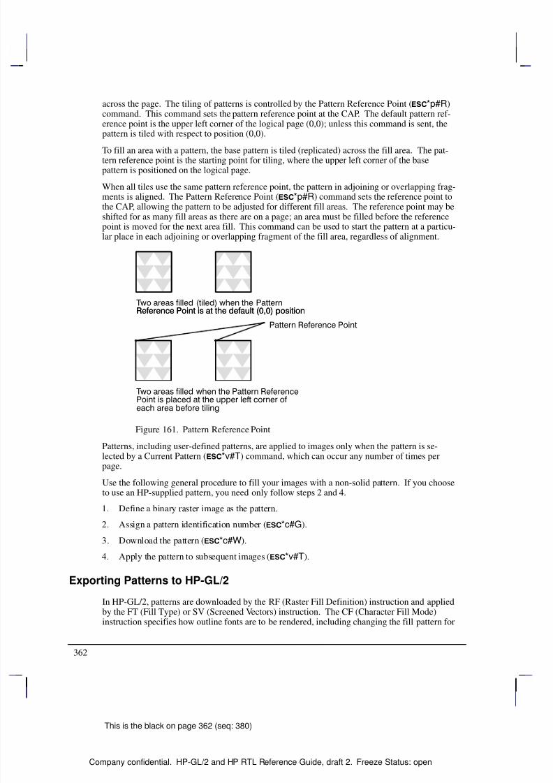
8/12/2019 HPGL2-RTL ReferenceGuide 5961-3526 540pages Sep96
http://slidepdf.com/reader/full/hpgl2-rtl-referenceguide-5961-3526-540pages-sep96 380/539
362
This is the black on page 362 (seq: 380)
Company confidential. HP-GL/2 and HP RTL Reference Guide, draft 2. Freeze Status: open
across the page. The tiling of patterns is controlled by the Pattern Reference Point (*p#R)command. This command sets the pattern reference point at the CAP. The default pattern ref-erence point is the upper left corner of the logical page (0,0); unless this command is sent, the
pattern is tiled with respect to position (0,0).To fill an area with a pattern, the base pattern is tiled (replicated) across the fill area. The pat-tern reference point is the starting point for tiling, where the upper left corner of the basepattern is positioned on the logical page.
When all tiles use the same pattern reference point, the pattern in adjoining or overlapping frag-ments is aligned. The Pattern Reference Point (*p#R) command sets the reference point tothe CAP, allowing the pattern to be adjusted for different fill areas. The reference point may beshifted for as many fill areas as there are on a page; an area must be filled before the referencepoint is moved for the next area fill. This command can be used to start the pattern at a particu-lar place in each adjoining or overlapping fragment of the fill area, regardless of alignment.
Figure 161. Pattern Reference Point
Patterns, including user-defined patterns, are applied to images only when the pattern is se-lected by a Current Pattern (*v#T) command, which can occur any number of times perpage.
Use the following general procedure to fill your images with a non-solid pattern. If you chooseto use an HP-supplied pattern, you need only follow steps 2 and 4.
1. Define a binary raster image as the pattern.
2. Assign a pattern identification number (*c#G).
3. Download the pattern (*c#W).
4. Apply the pattern to subsequent images (*v#T).
Exporting Patterns to HP-GL/2
In HP-GL/2, patterns are downloaded by the RF (Raster Fill Definition) instruction and appliedby the FT (Fill Type) or SV (Screened Vectors) instruction. The CF (Character Fill Mode)instruction specifies how outline fonts are to be rendered, including changing the fill pattern for
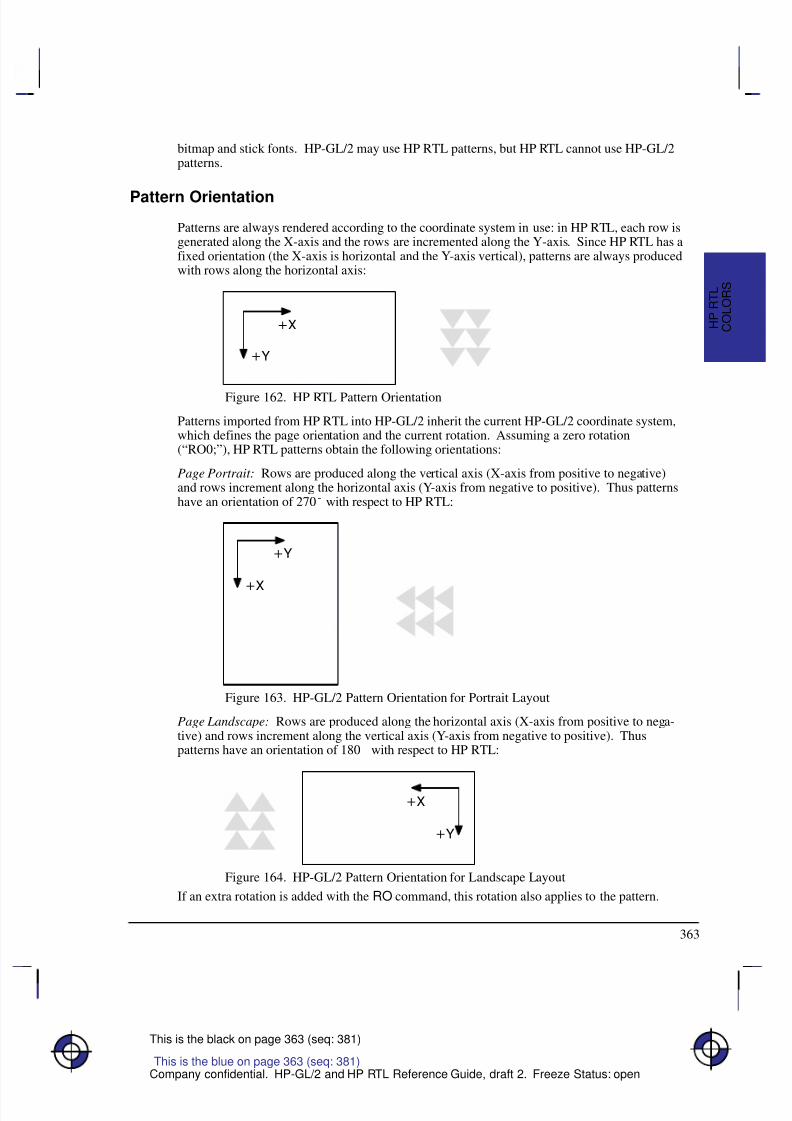
8/12/2019 HPGL2-RTL ReferenceGuide 5961-3526 540pages Sep96
http://slidepdf.com/reader/full/hpgl2-rtl-referenceguide-5961-3526-540pages-sep96 381/539
363
This is the black on page 363 (seq: 381)
Company confidential. HP-GL/2 and HP RTL Reference Guide, draft 2. Freeze Status: open
bitmap and stick fonts. HP-GL/2 may use HP RTL patterns, but HP RTL cannot use HP-GL/2patterns.
Pattern Orientation
Patterns are always rendered according to the coordinate system in use: in HP RTL, each row isgenerated along the X-axis and the rows are incremented along the Y-axis. Since HP RTL has afixed orientation (the X-axis is horizontal and the Y-axis vertical), patterns are always producedwith rows along the horizontal axis:
Figure 162. HP RTL Pattern Orientation
Patterns imported from HP RTL into HP-GL/2 inherit the current HP-GL/2 coordinate system,which defines the page orientation and the current rotation. Assuming a zero rotation(“RO0;”), HP RTL patterns obtain the following orientations:
Page Portrait: Rows are produced along the vertical axis (X-axis from positive to negative)and rows increment along the horizontal axis (Y-axis from negative to positive). Thus patternshave an orientation of 270 with respect to HP RTL:
Figure 163. HP-GL/2 Pattern Orientation for Portrait Layout
Page Landscape: Rows are produced along the horizontal axis (X-axis from positive to nega-tive) and rows increment along the vertical axis (Y-axis from negative to positive). Thuspatterns have an orientation of 180 with respect to HP RTL:
Figure 164. HP-GL/2 Pattern Orientation for Landscape Layout
If an extra rotation is added with the RO command, this rotation also applies to the pattern.
This is the blue on page 363 (seq: 381)
C O L O R S
H P R T L

8/12/2019 HPGL2-RTL ReferenceGuide 5961-3526 540pages Sep96
http://slidepdf.com/reader/full/hpgl2-rtl-referenceguide-5961-3526-540pages-sep96 382/539
364
This is the black on page 364 (seq: 382)
Company confidential. HP-GL/2 and HP RTL Reference Guide, draft 2. Freeze Status: open
Coincident Coordinate Systems: If you want the HP-GL/2 and HP RTL coordinate systems tocoincide, use the technique described on page 38.
8/12/2019 HPGL2-RTL ReferenceGuide 5961-3526 540pages Sep96
http://slidepdf.com/reader/full/hpgl2-rtl-referenceguide-5961-3526-540pages-sep96 383/539
365
This is the black on page 365 (seq: 383)
Company confidential. HP-GL/2 and HP RTL Reference Guide, draft 2. Freeze Status: open
Chapter 10: Interactions betweenPicture Elements
Once an image has been placed on the logical page (for example, some vectors or text usingHP-GL/2), and another image (for example, a scanned photograph) is to be added to it, you canspecify how they are to be merged together, and how patterns, colors, and transparency filterswill affect the final image. At the same time, using HP RTL, you can add color and patterns toyour images. You can even change the appearance of data that has already been prepared andsent to the device. First, some terms.
The destination image or current image is whatever is currently defined on the page. This in-cludes all images placed through previous operations, whether using HP-GL/2 or HP RTL.
Source data is the data that is about to be added to the page. There are two types of sourcedata: mask and raster.
Mask source is HP-GL/2 data. The source data acts like a stencil whose shape allows a
pattern or the selected pen’s color to pour through onto the page.
Raster source is HP RTL data, and may be specified by either the indexed or direct method
(see Specifying Colors on page 353). In the indexed method, each pixel identifies a paletteindex; in the direct method, each pixel is specified by its color components.
The meaning of “white” pixels depends on the type of image data: single-plane raster source, awhite pixel is one whose value is a 0-bit; otherwise, for indexed raster source, a white pixel isone that selects a white palette entry, and for direct raster source, a white pixel is one for whichall color primaries meet or exceed their white reference values. In HP-GL/2, source data isconsidered as a black mask, so there are no “white” pixels. Note that skipping over areas inraster mode automatically assigns index 0 (normally white) to empty areas; see Using Index 0on page 359 for more information.
There are two transparency modes, source transparency mode and pattern transparency mode.In both cases, the transparency mode affects only “white” pixels. When the mode is transpar-ent, the “white” pixels, as defined above, have no effect on the destination (the current image);when the mode is opaque, the “white” pixels are applied to the destination. By default, whitepixels are transparent for both HP RTL raster data and HP-GL/2 vector data.
Source transparency mode is a flag that specifies whether the “white” pixels in the source
image are transparent or opaque. In HP RTL, the source transparency is selected by theSource Transparency Mode command (*v#N); in HP-GL/2, there is no source transpar-ency. Note that on devices that do not support the Source Transparency Mode command,the HP-GL/2 TR (Transparency Mode) instruction may apply to HP RTL data—see The
Product Comparison Guide for HP Languages on HP Plotters and Large-Format Printers
for further guidance.
Pattern transparency mode is a flag that specifies whether the “white” pixels in the pattern
are transparent or opaque. In HP RTL, the pattern transparency is selected by the Pattern
This is the blue on page 365 (seq: 383)
I N T E R A C T I O
N S
H P R T L
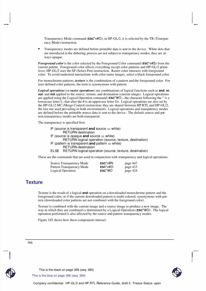
8/12/2019 HPGL2-RTL ReferenceGuide 5961-3526 540pages Sep96
http://slidepdf.com/reader/full/hpgl2-rtl-referenceguide-5961-3526-540pages-sep96 384/539
366
This is the black on page 366 (seq: 384)
Company confidential. HP-GL/2 and HP RTL Reference Guide, draft 2. Freeze Status: open
Transparency Mode command (*v#O); in HP-GL/2, it is selected by the TR (Transpar-ency Mode) instruction.
Transparency modes are defined before printable data is sent to the device. White dots that
are introduced in the dithering process are not subject to transparency modes; they are al-ways opaque.
Foreground color is the color selected by the Foreground Color command (*v#S) from thecurrent palette. Foreground color affects everything except color patterns and HP-GL/2 primi-tives; HP-GL/2 uses the SP (Select Pen) instruction. Raster color interacts with foregroundcolor. To avoid undesired interactions with color raster images, select a black foreground color.
For monochrome patterns, texture is the combination of a pattern and the foreground color. Foruser-defined color patterns, the term is synonymous with pattern.
Logical operations (or raster operations) are combinations of logical functions such as and, or,xor, and not applied to the source, texture, and destination (current image). Logical operationsare applied using the Logical Operation command (*l#O—the character following the * is a
lowercase letter L; that after the # is an uppercase letter O). Logical operations are also set bythe HP-GL/2 MC (Merge Control) instruction; they are shared between HP RTL and HP-GL/2,the last one used prevailing in both environments. Logical operations and transparency modesare defined before the printable source data is sent to the device. The default source and pat-tern transparency modes are both transparent.
The transparency is specified first:
IF (source is transparent and source white)RETURN destination
IF (source is opaque and source white)RETURN logical operation (source, texture, destination)
IF (pattern is transparent and pattern white)RETURN destination
ELSE RETURN logical operation (source, texture, destination)
These are the commands that are used in conjunction with transparency and logical operations:
Source Transparency Mode *v#N page 447Pattern Transparency Mode *v#O page 433Logical Operation *l#O page 424.
Texture
Texture is the result of a logical and operation on a downloaded monochrome pattern and theforeground color; or if the current downloaded pattern is multi-colored, synonymous with pat-tern (downloaded color patterns are not combined with the foreground color).
Texture is combined with the current image and a source image to produce a new image. Theway in which they are combined is determined by a Logical Operation (*l#O). The logicaloperation performed is also affected by the source and pattern transparency modes.
Figure 165 shows how these components interact.
This is the blue on page 366 (seq: 384)
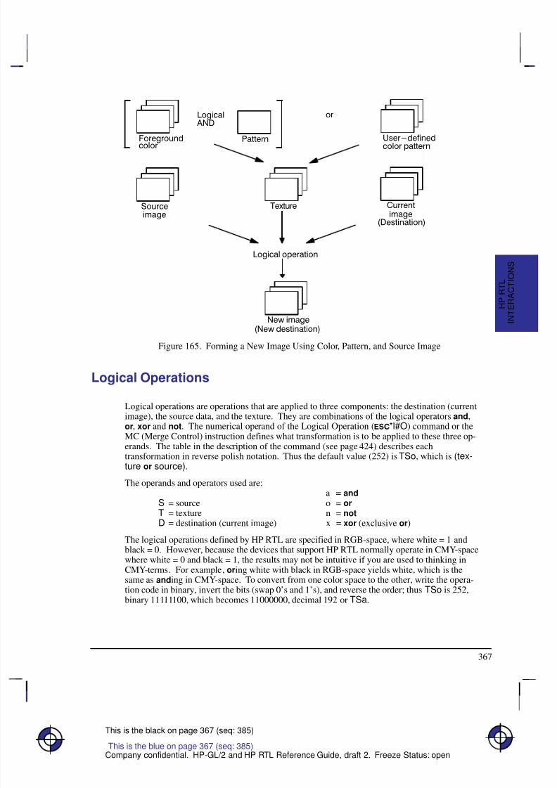
8/12/2019 HPGL2-RTL ReferenceGuide 5961-3526 540pages Sep96
http://slidepdf.com/reader/full/hpgl2-rtl-referenceguide-5961-3526-540pages-sep96 385/539
367
This is the black on page 367 (seq: 385)
Company confidential. HP-GL/2 and HP RTL Reference Guide, draft 2. Freeze Status: open
Figure 165. Forming a New Image Using Color, Pattern, and Source Image
Logical Operations
Logical operations are operations that are applied to three components: the destination (current
image), the source data, and the texture. They are combinations of the logical operators and,or, xor and not. The numerical operand of the Logical Operation (*l#O) command or theMC (Merge Control) instruction defines what transformation is to be applied to these three op-erands. The table in the description of the command (see page 424) describes eachtransformation in reverse polish notation. Thus the default value (252) is TSo, which is (tex-ture or source).
The operands and operators used are:a = and
S = source o = orT = texture n = notD = destination (current image) x = xor (exclusive or)
The logical operations defined by HP RTL are specified in RGB-space, where white = 1 and
black = 0. However, because the devices that support HP RTL normally operate in CMY-spacewhere white = 0 and black = 1, the results may not be intuitive if you are used to thinking inCMY-terms. For example, oring white with black in RGB-space yields white, which is thesame as anding in CMY-space. To convert from one color space to the other, write the opera-tion code in binary, invert the bits (swap 0’s and 1’s), and reverse the order; thus TSo is 252,binary 11111100, which becomes 11000000, decimal 192 or TSa.
This is the blue on page 367 (seq: 385)
I N T E R A C T I O
N S
H P R T L
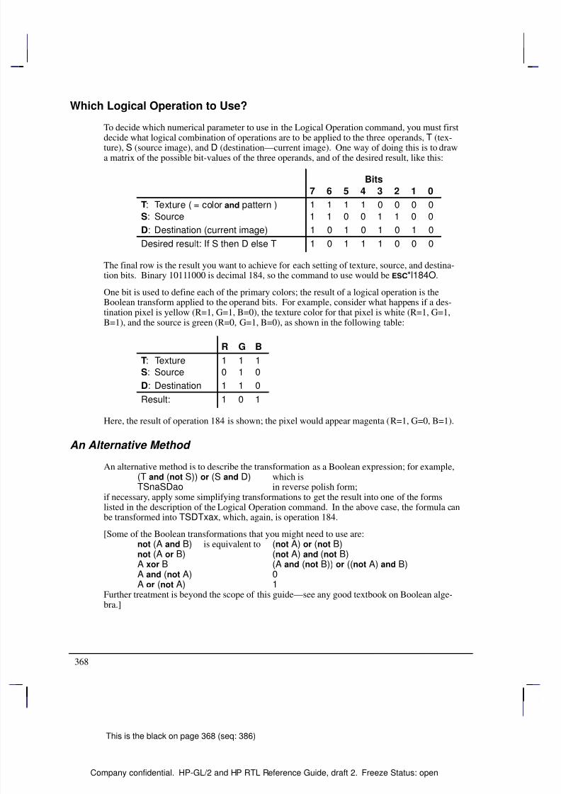
8/12/2019 HPGL2-RTL ReferenceGuide 5961-3526 540pages Sep96
http://slidepdf.com/reader/full/hpgl2-rtl-referenceguide-5961-3526-540pages-sep96 386/539
368
This is the black on page 368 (seq: 386)
Company confidential. HP-GL/2 and HP RTL Reference Guide, draft 2. Freeze Status: open
Which Logical Operation to Use?
To decide which numerical parameter to use in the Logical Operation command, you must first
decide what logical combination of operations are to be applied to the three operands, T (tex-ture), S (source image), and D (destination—current image). One way of doing this is to drawa matrix of the possible bit-values of the three operands, and of the desired result, like this:
Bits
7 6 5 4 3 2 1 0
T: Texture ( = color and pattern ) 1 1 1 1 0 0 0 0
S: Source 1 1 0 0 1 1 0 0
D: Destination (current image) 1 0 1 0 1 0 1 0
Desired result: If S then D else T 1 0 1 1 1 0 0 0
The final row is the result you want to achieve for each setting of texture, source, and destina-
tion bits. Binary 10111000 is decimal 184, so the command to use would be *l184O.One bit is used to define each of the primary colors; the result of a logical operation is theBoolean transform applied to the operand bits. For example, consider what happens if a des-tination pixel is yellow (R=1, G=1, B=0), the texture color for that pixel is white (R=1, G=1,B=1), and the source is green (R=0, G=1, B=0), as shown in the following table:
R G B
T: Texture 1 1 1
S: Source 0 1 0
D: Destination 1 1 0
Result: 1 0 1
Here, the result of operation 184 is shown; the pixel would appear magenta (R=1, G=0, B=1).
An Alternative Method
An alternative method is to describe the transformation as a Boolean expression; for example,(T and (not S)) or (S and D) which isTSnaSDao in reverse polish form;
if necessary, apply some simplifying transformations to get the result into one of the formslisted in the description of the Logical Operation command. In the above case, the formula canbe transformed into TSDTxax, which, again, is operation 184.
[Some of the Boolean transformations that you might need to use are:not (A and B) is equivalent to (not A) or (not B)
not (A or B) (not A) and (not B)A xor B (A and (not B)) or ((not A) and B)A and (not A) 0A or (not A) 1
Further treatment is beyond the scope of this guide—see any good textbook on Boolean alge-bra.]
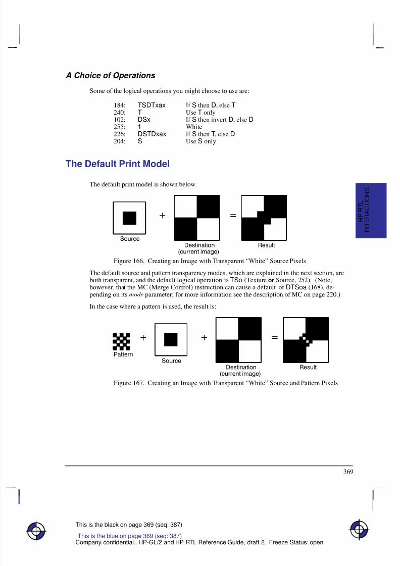
8/12/2019 HPGL2-RTL ReferenceGuide 5961-3526 540pages Sep96
http://slidepdf.com/reader/full/hpgl2-rtl-referenceguide-5961-3526-540pages-sep96 387/539
369
This is the black on page 369 (seq: 387)
Company confidential. HP-GL/2 and HP RTL Reference Guide, draft 2. Freeze Status: open
A Choice of Operations
Some of the logical operations you might choose to use are:
184: TSDTxax If S then D, else T240: T Use T only102: DSx If S then invert D, else D255: 1 White226: DSTDxax If S then T, else D204: S Use S only
The Default Print Model
The default print model is shown below.
Figure 166. Creating an Image with Transparent “White” Source Pixels
The default source and pattern transparency modes, which are explained in the next section, areboth transparent, and the default logical operation is TSo (Texture or Source, 252). (Note,however, that the MC (Merge Control) instruction can cause a default of DTSoa (168), de-
pending on its mode parameter; for more information see the description of MC on page 220.)In the case where a pattern is used, the result is:
Figure 167. Creating an Image with Transparent “White” Source and Pattern Pixels
This is the blue on page 369 (seq: 387)
I N T E R A C T I O
N S
H P R T L
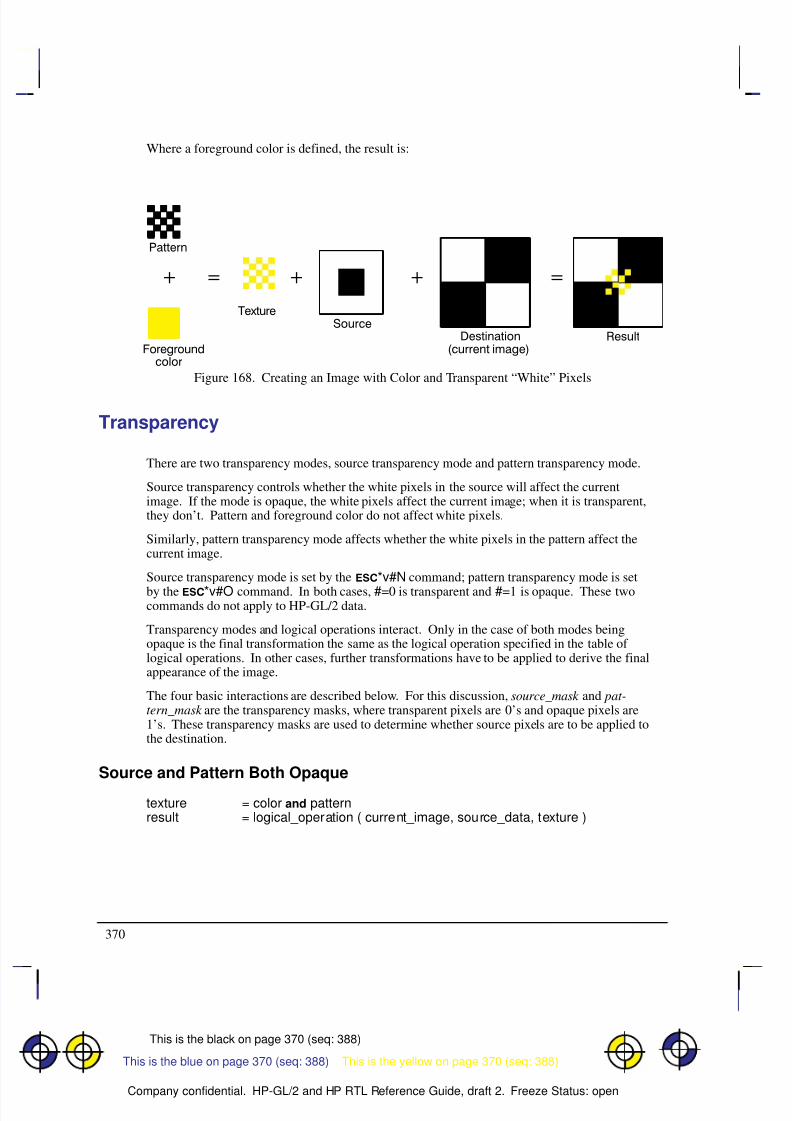
8/12/2019 HPGL2-RTL ReferenceGuide 5961-3526 540pages Sep96
http://slidepdf.com/reader/full/hpgl2-rtl-referenceguide-5961-3526-540pages-sep96 388/539
370
This is the black on page 370 (seq: 388)
Company confidential. HP-GL/2 and HP RTL Reference Guide, draft 2. Freeze Status: open
Where a foreground color is defined, the result is:
Figure 168. Creating an Image with Color and Transparent “White” Pixels
Transparency
There are two transparency modes, source transparency mode and pattern transparency mode.
Source transparency controls whether the white pixels in the source will affect the currentimage. If the mode is opaque, the white pixels affect the current image; when it is transparent,they don’t. Pattern and foreground color do not affect white pixels.
Similarly, pattern transparency mode affects whether the white pixels in the pattern affect thecurrent image.
Source transparency mode is set by the *v#N command; pattern transparency mode is set
by the *v#O command. In both cases, #=0 is transparent and #=1 is opaque. These twocommands do not apply to HP-GL/2 data.
Transparency modes and logical operations interact. Only in the case of both modes beingopaque is the final transformation the same as the logical operation specified in the table of logical operations. In other cases, further transformations have to be applied to derive the finalappearance of the image.
The four basic interactions are described below. For this discussion, source_mask and pat-tern_mask are the transparency masks, where transparent pixels are 0’s and opaque pixels are1’s. These transparency masks are used to determine whether source pixels are to be applied tothe destination.
Source and Pattern Both Opaque
texture = color and patternresult = logical_operation ( current_image, source_data, texture )
This is the yellow on page 370 (seq: 388)This is the blue on page 370 (seq: 388)
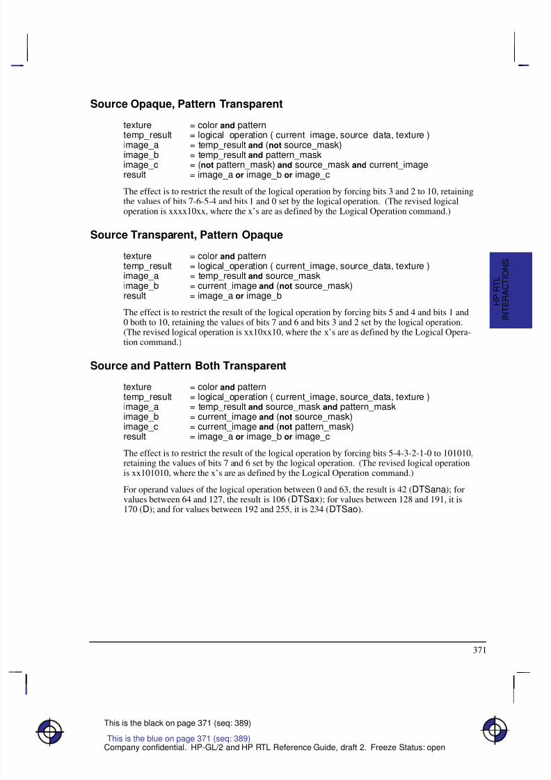
8/12/2019 HPGL2-RTL ReferenceGuide 5961-3526 540pages Sep96
http://slidepdf.com/reader/full/hpgl2-rtl-referenceguide-5961-3526-540pages-sep96 389/539
371
This is the black on page 371 (seq: 389)
Company confidential. HP-GL/2 and HP RTL Reference Guide, draft 2. Freeze Status: open
Source Opaque, Pattern Transparent
texture = color and pattern
temp_result = logical_operation ( current_image, source_data, texture )image_a = temp_result and (not source_mask)image_b = temp_result and pattern_maskimage_c = (not pattern_mask) and source_mask and current_imageresult = image_a or image_b or image_c
The effect is to restrict the result of the logical operation by forcing bits 3 and 2 to 10, retainingthe values of bits 7-6-5-4 and bits 1 and 0 set by the logical operation. (The revised logicaloperation is xxxx10xx, where the x’s are as defined by the Logical Operation command.)
Source Transparent, Pattern Opaque
texture = color and patterntemp_result = logical_operation ( current_image, source_data, texture )
image_a = temp_result and source_maskimage_b = current_image and (not source_mask)result = image_a or image_b
The effect is to restrict the result of the logical operation by forcing bits 5 and 4 and bits 1 and0 both to 10, retaining the values of bits 7 and 6 and bits 3 and 2 set by the logical operation.(The revised logical operation is xx10xx10, where the x’s are as defined by the Logical Opera-tion command.)
Source and Pattern Both Transparent
texture = color and patterntemp_result = logical_operation ( current_image, source_data, texture )
image_a = temp_result and source_mask and pattern_maskimage_b = current_image and (not source_mask)image_c = current_image and (not pattern_mask)result = image_a or image_b or image_c
The effect is to restrict the result of the logical operation by forcing bits 5-4-3-2-1-0 to 101010,retaining the values of bits 7 and 6 set by the logical operation. (The revised logical operationis xx101010, where the x’s are as defined by the Logical Operation command.)
For operand values of the logical operation between 0 and 63, the result is 42 (DTSana); forvalues between 64 and 127, the result is 106 (DTSax); for values between 128 and 191, it is170 (D); and for values between 192 and 255, it is 234 (DTSao).
This is the blue on page 371 (seq: 389)
I N T E R A C T I O
N S
H P R T L
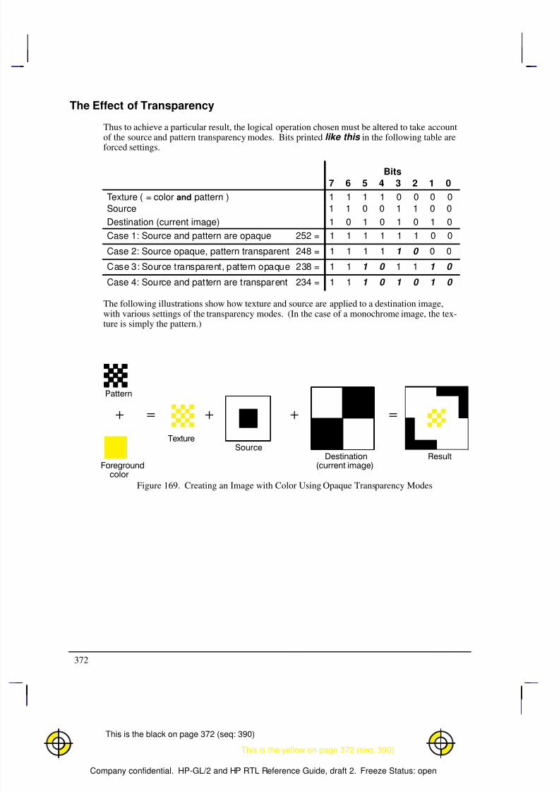
8/12/2019 HPGL2-RTL ReferenceGuide 5961-3526 540pages Sep96
http://slidepdf.com/reader/full/hpgl2-rtl-referenceguide-5961-3526-540pages-sep96 390/539
372
This is the black on page 372 (seq: 390)
Company confidential. HP-GL/2 and HP RTL Reference Guide, draft 2. Freeze Status: open
The Effect of Transparency
Thus to achieve a particular result, the logical operation chosen must be altered to take account
of the source and pattern transparency modes. Bits printed like this in the following table areforced settings.
Bits
7 6 5 4 3 2 1 0
Texture ( = color and pattern ) 1 1 1 1 0 0 0 0
Source 1 1 0 0 1 1 0 0
Destination (current image) 1 0 1 0 1 0 1 0
Case 1: Source and pattern are opaque 252 = 1 1 1 1 1 1 0 0
Case 2: Source opaque, pattern transparent 248 = 1 1 1 1 1 0 0 0
Case 3: Source transparent, pattern opaque 238 = 1 1 1 0 1 1 1 0
Case 4: Source and pattern are transparent 234 = 1 1 1 0 1 0 1 0
The following illustrations show how texture and source are applied to a destination image,with various settings of the transparency modes. (In the case of a monochrome image, the tex-ture is simply the pattern.)
Figure 169. Creating an Image with Color Using Opaque Transparency Modes
This is the yellow on page 372 (seq: 390)
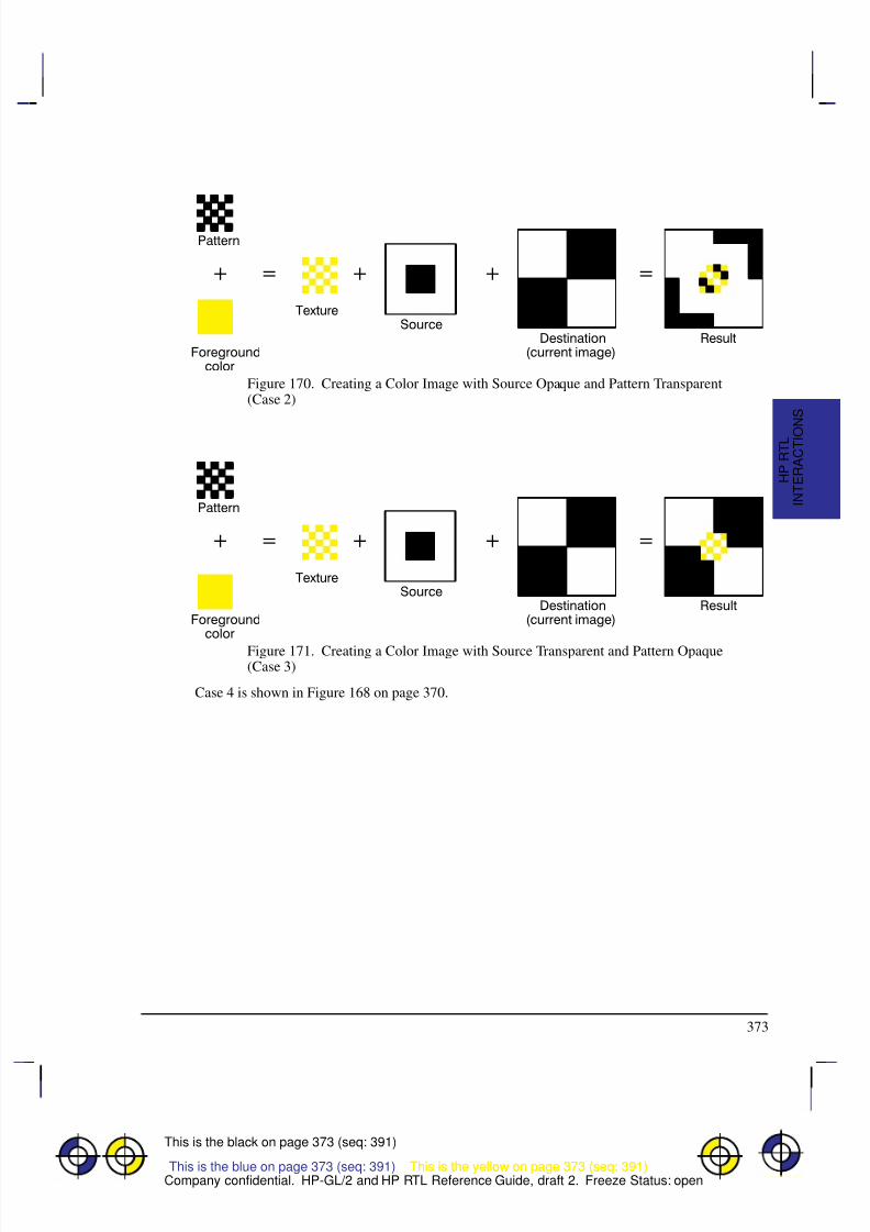
8/12/2019 HPGL2-RTL ReferenceGuide 5961-3526 540pages Sep96
http://slidepdf.com/reader/full/hpgl2-rtl-referenceguide-5961-3526-540pages-sep96 391/539
373
This is the black on page 373 (seq: 391)
Company confidential. HP-GL/2 and HP RTL Reference Guide, draft 2. Freeze Status: open
Figure 170. Creating a Color Image with Source Opaque and Pattern Transparent(Case 2)
Figure 171. Creating a Color Image with Source Transparent and Pattern Opaque(Case 3)
Case 4 is shown in Figure 168 on page 370.
This is the yellow on page 373 (seq: 391)This is the blue on page 373 (seq: 391) This is the yellow on page 373 (seq: 391)
I N T E R A C T I O
N S
H P R T L

8/12/2019 HPGL2-RTL ReferenceGuide 5961-3526 540pages Sep96
http://slidepdf.com/reader/full/hpgl2-rtl-referenceguide-5961-3526-540pages-sep96 392/539
374
This is the black on page 374 (seq: 392)
Company confidential. HP-GL/2 and HP RTL Reference Guide, draft 2. Freeze Status: open
8/12/2019 HPGL2-RTL ReferenceGuide 5961-3526 540pages Sep96
http://slidepdf.com/reader/full/hpgl2-rtl-referenceguide-5961-3526-540pages-sep96 393/539
375
This is the black on page 375 (seq: 393)
Company confidential. HP-GL/2 and HP RTL Reference Guide, draft 2. Freeze Status: open
Chapter 11: Transmitting Data
So far we have looked at several concepts regarding raster data, as well as discussing somecommands used for setting up the raster transfer. This section explains the basic commandsused actually to transfer the data.
Transferring Raster Data
When all the setup is complete, you tell the device to expect raster data by sending the HP RTL
command Start Raster Graphics (*r#A). The parameters in this command tell the devicewhether to start graphics at the left side of the logical page or at the CAP, and whether to startgraphics with or without scaling. When the device is in raster mode, some commands are al-lowed and some are ignored—see the list of commands on page 403 for details.
The Raster Line Path command (*b#L) specifies the vertical direction in which the rasterimage will “grow”. Because of problems that can occur if an image requires more memorythan the device has available, you are recommended to use the “downwards” direction(*b0L) in this command. See When Overflow Occurs on page NO TAG.
Once the device is in raster mode, you can send it data using two HP RTL commands: TransferRaster Data by Plane (*b#V), and Transfer Raster Data by Row/Block (*b#W). Thedata sent with these commands must be formatted according to the current compression meth-od—see Compressing Data on page 380.
The two Transfer commands are used to send raster data to the device in a row-by-row format.Transfer Raster Data by Plane (*b#V) increments the plane counter but not the row point-er; it is therefore used to send each plane in a multi-plane row except the last. Transfer RasterData by Row/Block (*b#W) moves the CAP to the next raster row, and is therefore used tosend the last plane of a multi-plane row.
When you have only one plane of data to print, you only need the second command, TransferRaster Data by Row/Block. You send each row of raster data with this command. After thedevice renders this data internally, the row counter is incremented, and the device is ready toreceive data for the next row. When you use a block-based compression method, you issue thiscommand only once for each block.
When all the data for an image has been sent, you exit raster graphics mode with the HP RTLcommand End Raster Graphics.
Use these commands to enter and exit raster mode and to send raster data to the device:
Start Raster Graphics *r#A page 448End Raster Graphics *rC page 419Transfer Raster Data by Plane *b#V[data] page 449Transfer Raster Data by Row/Block *b#W[data] page 451Compression Method *b#M page 408Y Offset *b#Y page 453Raster Line Path *b#L page 435.
This is the blue on page 375 (seq: 393)
D A T A T R A N S M I T
H P R T L
This is the blue on page 375 (seq: 393)

8/12/2019 HPGL2-RTL ReferenceGuide 5961-3526 540pages Sep96
http://slidepdf.com/reader/full/hpgl2-rtl-referenceguide-5961-3526-540pages-sep96 394/539
376
This is the black on page 376 (seq: 394)
Company confidential. HP-GL/2 and HP RTL Reference Guide, draft 2. Freeze Status: open
Note that the Compression Method command, the two transfer commands, the Y Offset com-mand, and the Raster Line Path command all begin with *b. You can combine thesecommands using the technique described on page 340. You must put the other commands be-
fore the transfer command in the combined command. Transfer commands (which must end ina capital letter, and are followed by data) can only end a combined command; they cannot be-gin one.
Implicit Start Raster Graphics
A Transfer Raster Data by Plane (*b#V[data]) or Transfer Raster Data by Row/Block (*b#W[data]) command is permitted with no preceding Start Raster Graphics (*r#A)command. Either transfer command implicitly puts the device into (unscaled) raster mode anduses the left edge of the logical page as the left graphics margin, corresponding to a Start RasterGraphics with parameter value 0. It is strongly recommended, however, that you start raster graphics explicitly using the Start Raster Graphics command.
Commands in Raster Mode
After an explicit or implicit Start Raster Graphics command, the device enters a restricted statecalled raster mode. This mode “locks out” (ignores) commands that would affect rendering of the graphics image. These commands remain locked out until raster mode is terminated by anexplicit or implicit End Raster Graphics command.
Some additional commands are ignored in scaled raster mode only. Scaled raster mode is ineffect after a Start Raster Graphics command with a value of 2 or 3 is received (and SourceRaster Width and Source Raster Height were specified), and until an implicit or explicit EndRaster Graphics command.
Commands that are neither explicitly ignored or explicitly allowed when the device is in rastermode cause an implicit End Raster Graphics command to be executed, and are then executed asusual.
Implicit End Raster Graphics
Receipt of any data other than an HP RTL command listed on page 403 as explicitly allowed orexplicitly ignored causes an implicit End Raster Graphics with all of its defined functionality.
It is strongly recommended, however, that you end raster graphics explicitly.
When Overflow Occurs*
Your device uses internal random-access memory (RAM) to store vector and raster data. Innormal operating mode, the device stores all data for an image before printing it in one pass.
It is possible, however, to send more data for one page than will fit in storage. This is morelikely to occur with raster data, since this data is more voluminous than vector data. (In mostcases, vector data is stored as endpoints, whereas raster data includes one bit of data for eachcolor-plane of each pixel of the image.) Some very complex vector drawings may also over-flow RAM.
If your images consistently overflow RAM and you have not expanded the RAM as much as
* Note that this section does not apply to all HP RTL devices.
This is the blue on page 376 (seq: 394)
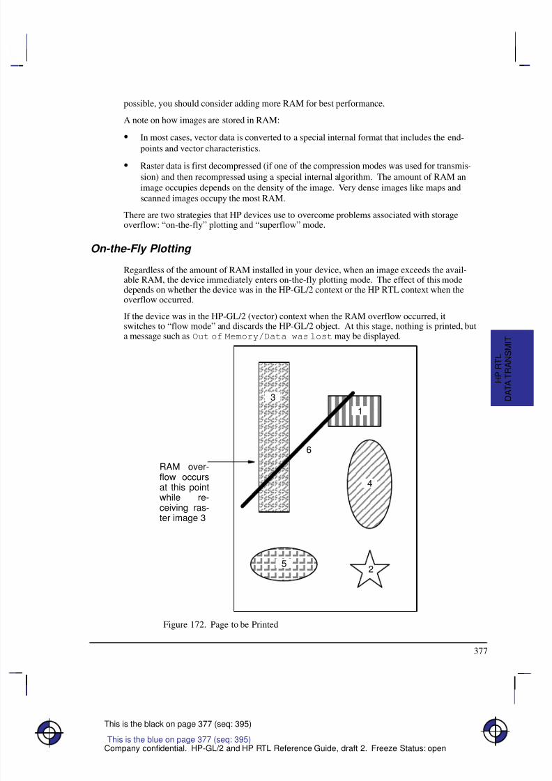
8/12/2019 HPGL2-RTL ReferenceGuide 5961-3526 540pages Sep96
http://slidepdf.com/reader/full/hpgl2-rtl-referenceguide-5961-3526-540pages-sep96 395/539
377
This is the black on page 377 (seq: 395)
Company confidential. HP-GL/2 and HP RTL Reference Guide, draft 2. Freeze Status: open
possible, you should consider adding more RAM for best performance.
A note on how images are stored in RAM:
In most cases, vector data is converted to a special internal format that includes the end-points and vector characteristics.
Raster data is first decompressed (if one of the compression modes was used for transmis-
sion) and then recompressed using a special internal algorithm. The amount of RAM animage occupies depends on the density of the image. Very dense images like maps andscanned images occupy the most RAM.
There are two strategies that HP devices use to overcome problems associated with storageoverflow: “on-the-fly” plotting and “superflow” mode.
On-the-Fly Plotting
Regardless of the amount of RAM installed in your device, when an image exceeds the avail-able RAM, the device immediately enters on-the-fly plotting mode. The effect of this modedepends on whether the device was in the HP-GL/2 context or the HP RTL context when theoverflow occurred.
If the device was in the HP-GL/2 (vector) context when the RAM overflow occurred, itswitches to “flow mode” and discards the HP-GL/2 object. At this stage, nothing is printed, buta message such as Out of Memory/Data was lost may be displayed.
  Â
  Â
  Â
  Â
  Â
  Â
  Â
  Â
  Â
  Â
  Â
  Â
À À À À À À
À À À À À À
À À À À À À
À À À À À À
É É É É
É É É É
É É É É
É É É É
É É É É
É É É É
É É É É
Ë Ë Ë Ë
Ë Ë Ë Ë
Ë Ë Ë Ë
Ë Ë Ë Ë
3
1
6
5
4
2
RAM over-flow occursat this pointwhile re-ceiving ras-ter image 3
Figure 172. Page to be Printed
This is the blue on page 377 (seq: 395)
D A T A T R A N S M I T
H P R T L
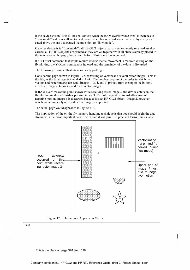
8/12/2019 HPGL2-RTL ReferenceGuide 5961-3526 540pages Sep96
http://slidepdf.com/reader/full/hpgl2-rtl-referenceguide-5961-3526-540pages-sep96 396/539
378
This is the black on page 378 (seq: 396)
Company confidential. HP-GL/2 and HP RTL Reference Guide, draft 2. Freeze Status: open
If the device was in HP RTL (raster) context when the RAM overflow occurred, it switches to“flow mode” and prints all vector and raster data it has received so far that are physically lo-cated above the one that caused the transition to “flow mode”.
Once the device is in “flow mode”, all HP-GL/2 objects that are subsequently received are dis-carded; all HP RTL objects are printed as they arrive, together with all objects already placed inthe same area of the page, that arrived before “flow mode” was entered.
If a Y Offset command that would require reverse media movement is received during on-the-fly plotting, the Y Offset command is ignored and the remainder of the data is discarded.
The following example illustrates on-the-fly plotting.
Consider the page shown in Figure 172, consisting of vectors and several raster images. This isthe file, as the final page is intended to look. The numbers represent the order in which thevectors and raster images are sent. Images 1, 3, 4, and 5, printed from the top to the bottom,are raster images. Images 2 and 6 are vector images.
If RAM overflows at the point shown while receiving raster image 3, the device enters on-the-
fly plotting mode and finishes printing image 3. Part of image 4 is discarded because of negative motion; image 6 is discarded because it is an HP-GL/2 object. Image 2, however,which was completely received before image 3, is printed.
The actual page would appear as in Figure 173.
The implication of the on-the-fly memory-handling technique is that you should begin the datastream with the most important data to be certain it will print. In practical terms, this usually
  Â
  Â
  Â
  Â
  Â
  Â
  Â
  Â
  Â
  Â
  Â
  Â
Ë Ë Ë Ë Ë
Ë Ë Ë Ë Ë
Ë Ë Ë Ë Ë
3
1
2
RAM overflowoccurred at thispoint while receiv-ing raster image 3
Figure 173. Output as it Appears on Media
À À À À À À
À À À À À À
À À À À À À
À À À À À À
5
É É É
É É É
4
Upper part ofimage 4 lostdue to nega-tive motion
Vector image 6not printed (re-ceived duringflow mode)
8/12/2019 HPGL2-RTL ReferenceGuide 5961-3526 540pages Sep96
http://slidepdf.com/reader/full/hpgl2-rtl-referenceguide-5961-3526-540pages-sep96 397/539
379
This is the black on page 379 (seq: 397)
Company confidential. HP-GL/2 and HP RTL Reference Guide, draft 2. Freeze Status: open
means sending vectors before a large raster image, since the device can do on-the-fly plottingof the raster image.
“Superflow” Mode
An improved algorithm is used on some devices, compared with that just described. Again,when there is not enough memory to process a request, data so far accumulated is flushed, butonly the minimum necessary to enable the processing of the new data.
Swaths (bands) of data are flushed each time an overflow occurs, the flushing continuing untilthere is sufficient memory to honor the request or until all swaths have been flushed.
Swaths are also flushed each time any type of object (vector or raster) is placed on the page atswath n and no negative motion is specified; in this case, all swaths up to and including swathn–1 are flushed. If any data is subsequently received for swaths up to n–1, it is lost and an errormessage is given.
The effect of this is that, provided pictures are properly ordered into bands, they are more likelyto be printed successfully. Whenever possible, send to the device first those objects that occupythe top of the page, and afterwards those that come below.
In both vector and raster cases, memory overflow causes the device to print the uppermost partof the picture, and release the associated memory. It is then able to accept more data.
Plane-by-Plane Printing and Scaling
This section applies to devices, such as electrostatic plotters, that print one plane of a completepage, followed by the next plane, and so on until the entire page has been printed. Other de-vices, such as ink-jet plotters, can print all planes at once; this section does not apply to thelatter type of device.
When scaling is on and you are using plane-by-plane printing, you cannot use the Y Offsetcommand (*b#Y) to move the CAP. For this reason it is necessary to exit raster graphicsmode before moving the CAP back to the top of the output between planes. Since exiting rastergraphics also resets the compression method to the default (0), you must set the compressionmethod again before going back into raster graphics mode.
Calculating the Y Offset value is more complicated for scaled printing than for unscaled print-ing. During unscaled printing, the device moves one physical row per row of data sent, so theY Offset value is simply equal to the number of data rows sent. However, during scaled print-ing, the device generally prints more (or fewer) physical rows than the actual number of datarows sent, so the number of physical rows no longer equals the number of data rows. Since youmust tell the Y Offset command the number of physical rows to move back the CAP, you mustcalculate the Y Offset based on how much the image was scaled.
The formula for calculating the Y Offset for scaled raster graphics is as follows:
offset round destination height720.0
resolutionwhere
round is a function that returns an integer after rounding.
This is the blue on page 379 (seq: 397)
D A T A T R A N S M I T
H P R T L
8/12/2019 HPGL2-RTL ReferenceGuide 5961-3526 540pages Sep96
http://slidepdf.com/reader/full/hpgl2-rtl-referenceguide-5961-3526-540pages-sep96 398/539
380
This is the black on page 380 (seq: 398)
Company confidential. HP-GL/2 and HP RTL Reference Guide, draft 2. Freeze Status: open
destination height is the value from the Destination Raster Height command, thatis, the height of the destination image in decipoints.
720.0 is the number of decipoints per inch.
resolution is the resolution in dots per inch (dpi) as specified in the SetGraphics Resolution command. If no resolution is set, use thedevice’s default resolution. Note that although any resolutionsetting is ignored during scaled raster graphics, the Y Offsetcommand is nonetheless sensitive to the current resolution set-ting. This is why the formula requires the resolution parameter.
In essence, the formula converts the destination raster height to inches, and multiplies it by thecurrent dots-per-inch setting to get the number of dots to move. Multiply this offset value by–1 (to cause the page to move backwards), and use this as the value (#) in the Y Offset com-mand, as in the Summary of Normal Execution Sequence on page 466.
If you specified destination raster width and not destination raster height, you can calculate the
destination height as follows:
destination height truncdestination widthsource width
source heightwhere
trunc is a function that returns an integer after truncation.
Due to the potential for rounding error, it is more accurate to specify explicitly destinationheight in HP RTL than to calculate it using this formula.
Compressing Data
Raster images normally require that you send a bit (1/8 byte) of data for each pixel; if theimage is in color, at least three bits are required per pixel, often much more. For this reason,raster image files are generally much larger than vector image files, in which only the endpointsare sent.
In order to cut down on the amount of data that must be sent for raster images, HP RTL offersseveral data compression methods. These methods use different “tricks” to reduce the quantityof data that must be transmitted. Most of the tricks involve having the device replicate identi-cal data instead of sending it explicitly.
You use the HP RTL command Compression Method (*b#M) to select a compression meth-od.
Note that data compression applies only to data transmission. As soon as the data is received
by the device, it is decompressed, and then interpreted according to the pixel encoding mode.Depending on the image and the compression method, a compressed image can be much small-er than an uncompressed one, with corresponding savings in data transmission time. For thisreason, we recommend using data compression whenever possible. There is, of course, a trade-off between the host compression time plus device decompression time and the saving intransmission time.
For ease of explanation, the examples in this section are very small and therefore do not showany significant reduction in the size of the data.
This is the blue on page 380 (seq: 398)
8/12/2019 HPGL2-RTL ReferenceGuide 5961-3526 540pages Sep96
http://slidepdf.com/reader/full/hpgl2-rtl-referenceguide-5961-3526-540pages-sep96 399/539
381
This is the black on page 381 (seq: 399)
Company confidential. HP-GL/2 and HP RTL Reference Guide, draft 2. Freeze Status: open
Another way of reducing the amount of data sent to the device is to use the Y Offset command(*b#Y). This allows you to send partial rows of data. The Transfer Raster Data by Plane(*b#V) and Transfer Raster Data by Row/Block (*b#W) commands also let you specify
empty rows or planes, by using a zero parameter.HP RTL supports seven data compression methods:
Run-length encoding (row-based) – method 1 page 383
Tagged Image File Format (TIFF) revision 4.0 “Packbits” encoding
(row-based) – method 2 page 383
Seed-row encoding (row-based) – method 3 page 384
Adaptive encoding (block-based) – method 5 page 387
Three CCITT methods for monochrome data – methods 6, 7, and 8 page 390.
In addition, there are two unencoded (uncompressed) methods:
Row-based unencoded transmission – method 0 page 381
Block-based unencoded transmission – method 4 page 381.
It is possible to mix compression methods on the same page. This allows you to use the mostefficient method for each row, or, for block-based methods, for each block. You can also mixrow-based and block-based methods in one image.
The following sections explain each data compression method. The method numbers refer tothe respective values of the Compression Method parameter (#).
Row-Based Unencoded (Compression Method 0)
This is the default method; there is no compression of data. The number of bits required foreach pixel is determined by the Configure Image Data (*v#W) or Simple Color (*r#U)command. For one bit per pixel, the most significant bit (bit 7) of the first byte corresponds tothe first pixel in the row; the least significant bit (bit 0) corresponds to the eighth pixel in therow; the most significant bit of the second byte corresponds to the ninth bit in the row, and soon.
Data for each row must end on a byte boundary. If the number of bits per row is not evenlydivisible by 8, you must still send a complete byte. For instance, if there are 2500 bits per row,you must send 313 bytes; the last four bits of the last byte can contain anything. You can usethe Source Raster Width command (*r#S) to clip off the unwanted data. You could also fillthe trailing bits with data that will index to a non-printing color, usually white.
For example, to send the string of characters “UUUUATT” to the device, you would use thecommand sequence: *r1A*b0m7WUUUUATT*rC.
Block-Based Unencoded (Compression Method 4)
This is basically the same as row-based unencoded, except that only one command is needed totransfer data for an entire block of data (Transfer Raster Data by Row/Block—*b#W).
The first four bytes of the block make up a 32-bit number specifying the number of pixels of data to expect for each row. The device uses this value to determine when to increment theplane and row pointers. Note that this number is sent only at the beginning of the block, not at
This is the blue on page 381 (seq: 399)
D A T A T R A N S M I T
H P R T L
8/12/2019 HPGL2-RTL ReferenceGuide 5961-3526 540pages Sep96
http://slidepdf.com/reader/full/hpgl2-rtl-referenceguide-5961-3526-540pages-sep96 400/539
382
This is the black on page 382 (seq: 400)
Company confidential. HP-GL/2 and HP RTL Reference Guide, draft 2. Freeze Status: open
the beginning of each row. Also, this number is a true 32-bit unsigned binary integer, not astring of ASCII digits that make up a number as is the case with many other HP RTL parame-ters. Each pixel may be defined by more than one bit of data.
As with the row-based unencoded method, each row must start and end on a byte boundary. If the number of pixels per row specified in the first four bytes of the block is not evenly divisibleby 8, it is rounded up to the next multiple of 8. For instance, if the first four bytes contain thenumber 2500, it is rounded up to 2504. Data is not clipped based on this four-byte number.Instead, the row is padded to or clipped at the Source Raster Width (*r#S). Similarly, theSource Raster Height (*r#T) command allows padding or clipping to the height of theimage.
When the row is completely defined, the row-pointer is incremented, and plane pointer is resetto 1, and the CAP is set to the left graphics margin. If the last row of data specifies an incom-plete row, or if all the planes have not been defined, the unspecified data is assumed to be 0.
With block-based transfers, data is still sent by row and by plane. For instance, with threeplanes per row, data for a block is transmitted as follows:
*b#W Transfer Raster Data by Row/Block [number of pixels per row] 32-bit integer value
row 1 plane 1 Data organized by row and plane
row 1 plane 2 .
row 1 plane 3 .
row 2 plane 1 .
row 2 plane 2
row 2 plane 3
.
.
row n plane 1
row n plane 2
row n plane 3If there is only one plane per row, the data for each plane is transmitted as follows:
*b#W Transfer Raster Data by Row/Block
[number of pixels per row] 32-bit integer value
row 1 Data organized by row
row 2 .
. .
. .
row n
The parameter value (#) in the Transfer Raster Data by Row/Block command (*b#W) refersto the size of the entire block, including the four-byte prefix; the value (#) is equal to
4 number of pixels per row 8 number of rows number of planes
The “number of pixels per row/8” expression, rounded up to the next integer, yields the numberof bytes per row. (The angular brackets in the formula represent the “ceiling function,” indicat-ing that the result should be rounded up.)
8/12/2019 HPGL2-RTL ReferenceGuide 5961-3526 540pages Sep96
http://slidepdf.com/reader/full/hpgl2-rtl-referenceguide-5961-3526-540pages-sep96 401/539
383
This is the black on page 383 (seq: 401)
Company confidential. HP-GL/2 and HP RTL Reference Guide, draft 2. Freeze Status: open
Run-Length Encoding (Compression Method 1)
With run-length encoding, the raster data consists of byte pairs: the first byte is a repetition
count, and the second byte is a data byte. The repetition count can range from 0 to 255, andtells how many times the following byte is to be repeated. A count of 0 means the followingbyte occurs only once and is not repeated. A count of 255 means the byte is repeated 255 timesfor a total of 256 occurrences.
Run-length encoding is a row-based encoding method; a separate Transfer Raster Data com-mand is required for each plane and row.
Run-length encoding relies on byte pairs. If the parameter value (#) in the Transfer Raster Datacommand is odd, the entire transfer sequence is ignored.
Assume you want to send the following data to the device. The data is shown as binary num-bers and as ASCII characters:
01010101 01010101 01010101 01010101 01000001 01010100 01010100
U U U U A T T
Using run-length encoding, you would use the following combined command to send the row.The numbers in parentheses must be sent as binary bytes. For instance, (3) is binary 00000011.The entire escape sequence is:
00011011 00101010 01100010 00110001 01101101 00110110 01010111 ...
* b 1 m 6 W
... 00000011 01010101 00000000 01000001 00000001 01010100
(3) U (0) A (1) T
where
1 m means compression method 1 (run-length encoding).
6 W means there are six bytes of data following. Note that this is thelength of the compressed data, not the uncompressed data.
(3) U means repeat the “U” pattern 3 times for a total of four bytes.
(0) A means do not repeat the “A” pattern.
(1) T means repeat the “T” pattern once for a total of two bytes.
The data transfer sequence would be: *r1A*b1m6W(3)U(0)A(1)T*rC using thenotation for binary numbers described above.
TIFF Packbits Encoding (Compression Method 2)
Tagged Image File Format (TIFF) “packbits” encoding is a combination of row-basedunencoded and run-length encoding (methods 0 and 1). You can mix unencoded, orliteral, bytes with repeated bytes.
TIFF Packbits encoding is a row-based encoding method. A separate Transfer Raster Datacommand is required for each plane and row.
This is the blue on page 383 (seq: 401)
D A T A T R A N S M I T
H P R T L
8/12/2019 HPGL2-RTL ReferenceGuide 5961-3526 540pages Sep96
http://slidepdf.com/reader/full/hpgl2-rtl-referenceguide-5961-3526-540pages-sep96 402/539
384
This is the black on page 384 (seq: 402)
Company confidential. HP-GL/2 and HP RTL Reference Guide, draft 2. Freeze Status: open
With TIFF Packbits encoding, raster data is always preceded by a control byte. The controlbyte can fall into three ranges:
0 to 127 There are from 1 to 128 literal data bytes following the control byte. 0 means 1
literal byte; 127 means 128 literal bytes, and so on.
–1 to –127 The data byte following the control byte is repeated the number of times repre-
sented by the absolute value of the control byte. (Negative numbers are
represented by their two’s complement, that is, the number of identical bytes is
equal to –(control byte) + 1.)
–128 This control byte is ignored, and the next byte is treated as a control byte.
Assume you want to send the same data as shown with run-length encoding to the device:
01010101 01010101 01010101 01010101 01000001 01010100 01010100
U U U U A T T
Using TIFF Packbits encoding, you could use the following combined command to send the
row. As with run-length encoding, the numbers in parentheses must be sent as binary bytes.For instance, (–3), the two’s complement of (3), is binary 11111101, decimal 253. Spaces areadded for clarity.
* b 2m 6W (–3)U (0)A (–1)T
where 2 m means compression method 2 (TIFF Packbits encoding).
6 W means there are six bytes of data following. Note that this is thelength of the compressed data, not the uncompressed data.
(–3) U means repeat the “U” pattern 3 times for a total of four bytes.
(0) A means the “A” pattern is a 1-byte literal.
(–1) T means repeat the “T” pattern once for a total of two bytes.
Another valid way to code this data is with the following combined command:
* b 2m 6W (–3)U (2)ATT
Here, the last three bytes are sent as a literal ((2)ATT).
Again, the entire data transfer sequence would be:
*r1A*b2m6W(–3)U(0)A(–1)T*rCor *r1A*b2m6W(–3)U(2)ATT*rC
using the notation for binary numbers described above for run-length encoding.
When using TIFF Packbits encoding, it is more efficient to code two consecutive identical by-tes as a repeated byte than as a literal. However, if the repeated bytes are preceded and
followed by literal bytes, it is more efficient to code the entire group as literal bytes. It is al-ways most efficient to code three identical bytes as a repeated byte.
Seed-Row or Delta-Row Encoding (Compression Method 3)
Seed-row encoding describes a raster row by recording only the changes from the previous row(the seed row). Seed-row encoding is sometimes called delta row compression because it iden-
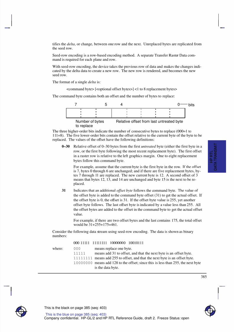
8/12/2019 HPGL2-RTL ReferenceGuide 5961-3526 540pages Sep96
http://slidepdf.com/reader/full/hpgl2-rtl-referenceguide-5961-3526-540pages-sep96 403/539
385
This is the black on page 385 (seq: 403)
Company confidential. HP-GL/2 and HP RTL Reference Guide, draft 2. Freeze Status: open
tifies the delta, or change, between one row and the next. Unreplaced bytes are replicated fromthe seed row.
Seed-row encoding is a row-based encoding method. A separate Transfer Raster Data com-mand is required for each plane and row.
With seed-row encoding, the device takes the previous row of data and makes the changes indi-cated by the delta data to create a new row. The new row is rendered, and becomes the newseed row.
The format of a single delta is:
<command byte> [<optional offset bytes>] <1 to 8 replacement bytes>
The command byte contains both an offset and the number of bytes to replace:
7 5 4 0
Number of bytesto replace
Relative offset from last untreated byte
bits
The three higher-order bits indicate the number of consecutive bytes to replace (000=1 to111=8). The five lower-order bits contain the offset relative to the current byte of the byte to bereplaced. The values of the offset have the following definitions:
0–30 Relative offset of 0–30 bytes from the first untreated byte (either the first byte in a
row, or the first byte following the most recent replacement byte). The first offset
in a raster row is relative to the left graphics margin. One to eight replacement
bytes follow this command byte.
For example, assume that the current byte is the first byte in the row. If the offsetis 7, bytes 0 through 6 are unchanged; and if there are five replacement bytes, by-
tes 7 through 11 are replaced. The new current byte is 12. A second offset of 3means that bytes 12, 13, and 14 are unchanged and byte 15 is the next to be re-placed.
31 Indicates that an additional offset byte follows the command byte. The value of
the offset byte is added to the command byte offset (31) to get the actual offset. If
the offset byte is 0, the offset is 31. If the offset byte value is 255, yet another
offset byte follows. The last offset byte is indicated by a value less than 255. All
the offset bytes are added to the offset in the command byte to get the actual offset
value.
For example, if there are two offset bytes and the last contains 175, the total offsetwould be 31+255+175=461.
Consider the following data stream using seed-row encoding. The data is shown as binarynumbers:
000 11111 11111111 10000000 10010111
where: 000 means replace one byte.
11111 means add 31 to offset, and that the next byte is an offset byte.
11111111 means add 255 to offset, and that the next byte is an offset byte.
10000000 means add 128 to the offset; since this is less than 255, the next byte
is the data byte.
This is the blue on page 385 (seq: 403)
D A T A T R A N S M I T
H P R T L
8/12/2019 HPGL2-RTL ReferenceGuide 5961-3526 540pages Sep96
http://slidepdf.com/reader/full/hpgl2-rtl-referenceguide-5961-3526-540pages-sep96 404/539
386
This is the black on page 386 (seq: 404)
Company confidential. HP-GL/2 and HP RTL Reference Guide, draft 2. Freeze Status: open
10010111 replaces the byte at an offset of 31 + 255 + 128 = 414 bytes.
The seed row is initialized to 0 whenever raster mode is entered. Every raster transfer affectsthe seed row, regardless of the compression method; this allows seed-row encoding to be com-
bined with other methods to achieve better compression performance.
A vertical offset also affects the seed row. The Y Offset command (*b#Y) skips rows, leav-ing them blank, and sets the seed row to zero. *b0Y moves down zero rows (or up, if theRaster Line Path command specified upward movement) and sets the seed row to zero.
Seed-Row Encoding and Raster Width
The width of the seed row is equal to the Source Raster Width (*r#S).
The Transfer Raster Data commands (*b#V and *b#W) both contain a number (#) of bytes of data to expect for the entire command. If this byte count is reached before the literalreplacement count is met, the byte count has precedence, and no further bytes are replaced inthat row. Data beyond the byte count is parsed as ASCII commands and not as binary data.
Seed-Row Encoding and Multi-Plane Data
When you are using more than one plane of data per row, the device maintains a seed row foreach plane. This allows seed-row compression to operate on each plane of graphics indepen-dently. However, a Y Offset affects all planes and seed rows simultaneously.
Programming with Seed-Row Encoding
With seed-row encoding, if only one bit in a row is different from the preceding row, then onlyone replacement byte must be sent (with its location specified in one or more command bytes).Here, seed-row encoding is very efficient. However, if a row is completely different from thepreceding row, then the entire row must be transmitted. In this case, another compressionmethod might be more efficient. For this reason, seed-row encoding is often mixed with othercompression methods for greatest efficiency.
In order to mix compression methods, it is important to understand how the seed row is affectedby various HP RTL commands.
Effect of Other Commands on the Seed Row
The seed row is updated by all row-based graphics transfers. This means that data sent withany row-based compression method is available as a seed row. (In multi-plane images, a sepa-rate seed row is updated for each plane.)
The seed row is zeroed by the Start Raster Graphics, End Raster Graphics, and Y Offset com-
mands. If there is more than one plane of data, all seed rows are zeroed. In addition, the seedrow is zeroed at the completion of any block-based transfer.
Note the effect of the following commands when the device is in raster mode (after a Start Ras-ter Graphics command) and seed-row encoding is active:
*b0W Transfer Raster Data by Row/Block. Repeats the previous row. The seedrow is unchanged.
*b1Y Move down one raster row. The seed row is set to zeros.
8/12/2019 HPGL2-RTL ReferenceGuide 5961-3526 540pages Sep96
http://slidepdf.com/reader/full/hpgl2-rtl-referenceguide-5961-3526-540pages-sep96 405/539
387
This is the black on page 387 (seq: 405)
Company confidential. HP-GL/2 and HP RTL Reference Guide, draft 2. Freeze Status: open
*b0Y Move down zero raster rows (that is, do not move the CAP). The seedrow is set to zeros.
Horizontal CAP moves have no effect on the seed row.
Example of Seed-Row Encoding
The following data is to be compressed using seed-row encoding. It is assumed there is onlyone plane of data. All graphics data is given in binary. The italicized bytes are the ones re-placed using seed-row encoding:
Byte #: 1 2 3 4 5
Row 1: 00000000 11111111 00000000 00000000 00000000Row 2: 00000000 11111111 11110000 00000000 00000000Row 3: 00001111 11111111 11110000 10101010 10101010
The following HP RTL commands generate the data shown above:
*r1A
Start Raster Graphics initializes the seed row to all zeros.
*b3m2W 000 00001 11111111 [data is shown in binary]
Compression Method to 3 (seed-row encoding) and Transfer Raster Data by Row/ Block for row 1. One byte is replaced. The command byte signifies a single bytereplacement (top three bits are 0) and the replacement occurs with an offset of 1 bytefrom the current position (lower five bits contain a relative offset of 1). The replace-ment byte follows and contains 11111111.
*b2W 000 00010 11110000 [data is shown in binary]
Transfer Raster Data by Row/Block for row 2. One byte is replaced. The command
byte signifies a single byte replacement (top three bits are 0) and the replacement oc-curs with an offset of 2 bytes from the current position (lower five bits contain arelative offset of 2). The replacement byte follows and contains 11110000.
*b5W 000 00000 00001111 001 00010 10101010 10101010 [data is shown in binary]
Transfer Raster Data by Row/Block for row 3. Three bytes are replaced using twocommands. The first command byte signifies a single byte replacement (top three bitsare 0) and the replacement occurs with an offset of 0 bytes from the current position(lower five bits contain a relative offset of 0). The replacement byte follows and con-tains 00001111. The second command calls for the replacement of two bytes (topthree bits are 001) and the replacement occurs with an offset of 2 bytes from the cur-rent untreated position (lower five bits contain a relative offset of 2). The two
replacement bytes follow the command byte.
Adaptive Encoding (Compression Method 5)
Adaptive compression uses compression methods 0 to 3 to compress optimally an entire block of data. When the row data within a block is no longer optimally compressed by one method,the compression method can be changed to adapt to the data. Adaptive compression alsoallows the specification of empty or duplicate rows to skip white space or replicate identicalrows within a block.
This is the blue on page 387 (seq: 405)
D A T A T R A N S M I T
H P R T L
8/12/2019 HPGL2-RTL ReferenceGuide 5961-3526 540pages Sep96
http://slidepdf.com/reader/full/hpgl2-rtl-referenceguide-5961-3526-540pages-sep96 406/539
388
This is the black on page 388 (seq: 406)
Company confidential. HP-GL/2 and HP RTL Reference Guide, draft 2. Freeze Status: open
In adaptive compression, a raster image is interpreted as a block of data, rather than as individ-ual rows. The Transfer Raster Data by Row/Block command (*b#W) is sent only once atthe beginning of a raster transfer; its value field specifies the number of bytes in the block. The
block size of the compressed data is limited to 32 767 bytes. To transfer more bytes, moreblocks can be sent.
Adaptive compression uses three control bytes at the beginning of each row within the block.The first of these bytes, the command byte, identifies the type of compression for that row. Thefollowing two bytes specify either the number of bytes within the row or the number of dupli-cate or empty rows. The following shows the format of an adaptive compression raster row:
<command byte><# of bytes or rows><# of bytes or rows><raster data>
The command byte designates the compression method, an empty row, or a duplicate row. Thefollowing shows the command byte values, which are sent in binary format:
Byte = 0 Unencoded1 Run-Length Encoding
2 Tagged Image File Format (TIFF) revision 4.03 Delta Row4 Empty Row5 Duplicate Row
If an out-of-range command byte is encountered on a row, the remainder of the block isskipped, the CAP is not updated, and the seed row is cleared.
For cases 0 to 3, the two-byte binary field (# of bytes or rows) specifies the row length (that is,the total number of bytes to be transferred for that row within the raster block). For cases 4 and5, this field defines the number of empty or duplicate rows to be encountered after the currentrow, including the current row. The most significant byte (high byte) of this field is sent first,followed by the least significant byte (low byte).
The maximum value for # of bytes or rows is 65 535; however, the image is clipped to the log-
ical page. The value does not include the three control bytes (the command byte and itself).Values 0 to 3 indicate the identical compression methods described previously. Values 4 and 5are explained below.
Empty Row A command byte of 4 causes a row of zeros to be printed. The number of rowsprinted is contained in # of bytes or rows, following the command byte. An empty-row opera-tion resets the seed row to 0 and updates CAP.
Duplicate Row A command byte of 5 causes the previous row to be printed again the numberof times contained in # of bytes or rows, following the command byte. A duplicate-row opera-tion updates CAP, but does not change the seed row.
Adaptive Compression Guidelines
Compression methods cannot be mixed within one row.
Within a block, the seed row is updated by every raster compression method or type of row.For example, a row compressed with method 2 updates the seed row, while the effect of anempty row initializes the seed row to zeros. Maintaining the seed row allows method 3 tobe mixed with other methods in order to achieve optimal compression performance.
CAP is updated with each row of the raster block.
The Y Offset command moves the entire block of raster data and also initializes the seedrow to zeros. The seed row is set to 0 even if the Y Offset is 0.
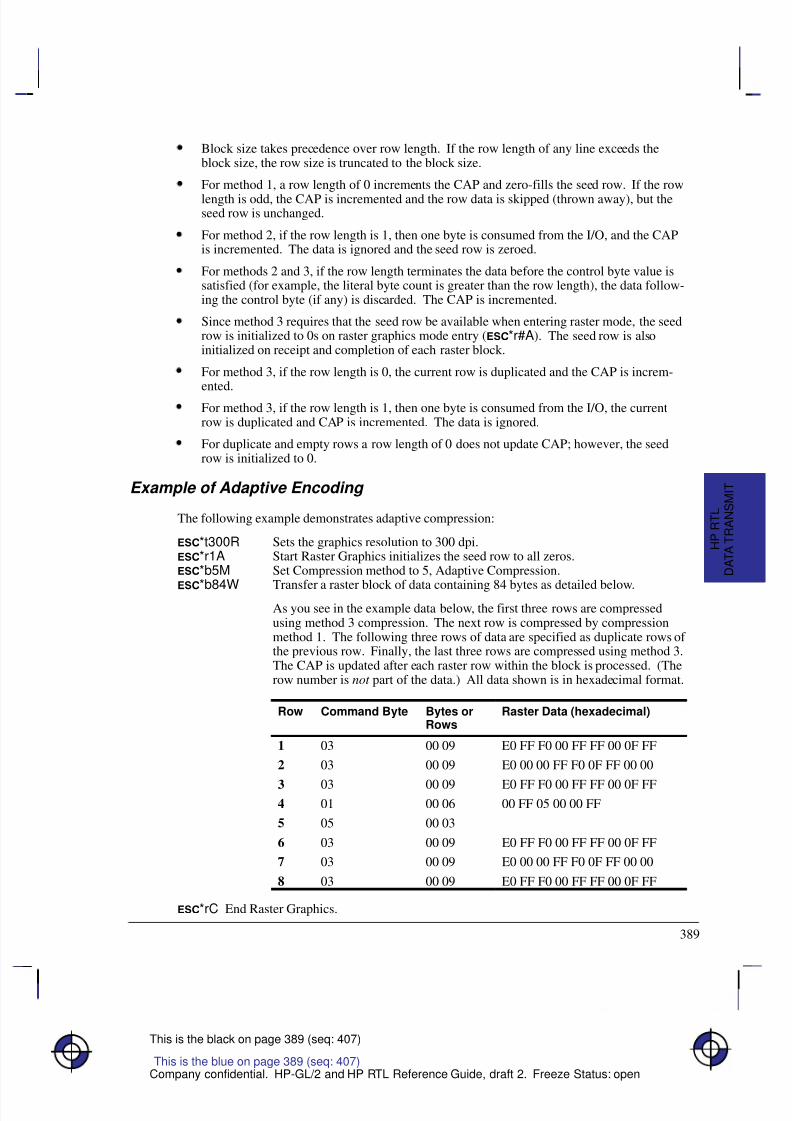
8/12/2019 HPGL2-RTL ReferenceGuide 5961-3526 540pages Sep96
http://slidepdf.com/reader/full/hpgl2-rtl-referenceguide-5961-3526-540pages-sep96 407/539
389
This is the black on page 389 (seq: 407)
Company confidential. HP-GL/2 and HP RTL Reference Guide, draft 2. Freeze Status: open
Block size takes precedence over row length. If the row length of any line exceeds theblock size, the row size is truncated to the block size.
For method 1, a row length of 0 increments the CAP and zero-fills the seed row. If the row
length is odd, the CAP is incremented and the row data is skipped (thrown away), but theseed row is unchanged.
For method 2, if the row length is 1, then one byte is consumed from the I/O, and the CAPis incremented. The data is ignored and the seed row is zeroed.
For methods 2 and 3, if the row length terminates the data before the control byte value issatisfied (for example, the literal byte count is greater than the row length), the data follow-ing the control byte (if any) is discarded. The CAP is incremented.
Since method 3 requires that the seed row be available when entering raster mode, the seedrow is initialized to 0s on raster graphics mode entry (*r#A). The seed row is alsoinitialized on receipt and completion of each raster block.
For method 3, if the row length is 0, the current row is duplicated and the CAP is increm-
ented.For method 3, if the row length is 1, then one byte is consumed from the I/O, the currentrow is duplicated and CAP is incremented. The data is ignored.
For duplicate and empty rows a row length of 0 does not update CAP; however, the seedrow is initialized to 0.
Example of Adaptive Encoding
The following example demonstrates adaptive compression:
*t300R Sets the graphics resolution to 300 dpi.*r1A Start Raster Graphics initializes the seed row to all zeros.*b5M Set Compression method to 5, Adaptive Compression.
*b84W Transfer a raster block of data containing 84 bytes as detailed below.As you see in the example data below, the first three rows are compressedusing method 3 compression. The next row is compressed by compressionmethod 1. The following three rows of data are specified as duplicate rows of the previous row. Finally, the last three rows are compressed using method 3.The CAP is updated after each raster row within the block is processed. (Therow number is not part of the data.) All data shown is in hexadecimal format.
Row Command Byte Bytes orRows
Raster Data (hexadecimal)
1 03 00 09 E0 FF F0 00 FF FF 00 0F FF
2 03 00 09 E0 00 00 FF F0 0F FF 00 00
3 03 00 09 E0 FF F0 00 FF FF 00 0F FF4 01 00 06 00 FF 05 00 00 FF
5 05 00 03
6 03 00 09 E0 FF F0 00 FF FF 00 0F FF
7 03 00 09 E0 00 00 FF F0 0F FF 00 00
8 03 00 09 E0 FF F0 00 FF FF 00 0F FF
*rC End Raster Graphics.
This is the blue on page 389 (seq: 407)
D A T A T R A N S M I T
H P R T L
8/12/2019 HPGL2-RTL ReferenceGuide 5961-3526 540pages Sep96
http://slidepdf.com/reader/full/hpgl2-rtl-referenceguide-5961-3526-540pages-sep96 408/539
390
This is the black on page 390 (seq: 408)
Company confidential. HP-GL/2 and HP RTL Reference Guide, draft 2. Freeze Status: open
CCITT Encoding Methods
The first four bytes of the Transfer Raster Data by Row/Block (*b#W) command are a
32-bit unsigned binary integer that specifies the number of pixels in a row. After decoding, anydata exceeding the specified Source Raster Width (*r#S) is clipped, and any incompletelyspecified rows are appended with 0s. If Source Raster Height (*r#T) is specified, unde-fined rows are zero-filled and excess rows are clipped.
CCITT Groups 3 and 4 encoding methods are by current definition monochrome compressionmethods, that is, data is sent for one plane only. The colors defined for indexes 0 and 1 are al-ways used for printing, regardless of how many planes were defined with the Set Number of Bits per Index byte of the HP RTL command Configure Image Data. When index 0 is set to acolor other than white, a two-color image results: index 0’s color appears wherever a “0” bit issent, and index 1’s color appears wherever a “1” bit is sent. The CCITT methods are particu-larly useful for text data.
A transfer command with a count of 4 is analogous to sending *b0W in compression meth-od 0; nothing is transferred but the seed row is zeroed.
Since methods 6, 7, and 8 are defined only for monochrome devices, selecting any of thesemethods causes the device to assume that all data planes except the first are zeroed; that is, thedata is interpreted as 0s and 1s that are to be rendered in the colors currently defined as index 0and 1, respectively. The number of bits per index as set by the Configure Image Data(*v#W) command and the palette are unchanged.
CCITT Group 3 One-Dimensional Encoding (Compression Method 6)
CCITT Group 3 one-dimensional encoding is a block-based compression method that uses astatistical encoding similar to Huffman encoding. The length of alternating white and black (0-and 1-bit) runs are calculated, and then a table lookup is employed to output the correspondingbinary codes. Refer to CCITT Fascicle VII.3 Recommendation T.4 for details.
CCITT Group 3 Two-Dimensional Encoding (Compression Method 7)
CCITT Group 3 two-dimensional encoding is similar to CCITT Group 3 one-dimensional en-coding; row 1 uses one-dimensional encoding, and rows 2 through K–1 are sent usingtwo-dimensional encoding, where K is the K-factor used when the data was encoded. Refer toCCITT Fascicle VII.3 Recommendation T.4 for details.
CCITT Group 4 Encoding (Compression Method 8)
CCITT Group 4 encoding is a block-based compression method similar to the CCITT Group 3encoding methods, except that all encoding is two-dimensional; it does not include end-of-linedelimiters, and does not allow padding to byte boundaries. Refer to CCITT Fascicle VII.3
Recommendation T.6 for details.
8/12/2019 HPGL2-RTL ReferenceGuide 5961-3526 540pages Sep96
http://slidepdf.com/reader/full/hpgl2-rtl-referenceguide-5961-3526-540pages-sep96 409/539
391
This is the black on page 391 (seq: 409)
Company confidential. HP-GL/2 and HP RTL Reference Guide, draft 2. Freeze Status: open
Chapter 12: Interactions betweenHP RTL and Other Systems
Interactions with Physical Device Settings
Potentially, the settings of the front panel of a plotter or printer may affect the resolution of printing, whether color or monochrome output is to be produced, and other parameters concern-
ing the overall rendering of data. See the documentation associated with the device for moredetails.
Interactions with HP-GL/2
Subject to some constraints, you can combine, on the same page, images defined by HP RTLand vector graphics produced by HP-GL/2. HP RTL interacts with HP-GL/2 in several ways.When HP-GL/2 vector data and HP RTL raster data are combined, their temporal order is main-tained, and each source component is combined with the destination bitmap according to theprint model state variable settings in effect when that component was issued. By default, whiteis transparent in both environments. The following table summarizes these interactions andtells you where to turn for more information. Section names in italics refer to section titles;
command names refer to command descriptions in Chapter 14. You can find a full descriptionof all HP-GL/2 instructions in Part 2 of this book.
Summary of HP-GL/2 Interactions
Interaction Description
Transferring the HP-GL/2 pen positionto the HP RTL Current Active Position(CAP) and conversely
See Changing Language Contexts and Modes onpage 393, the Enter RTL Mode command on page422, and the Enter HP-GL/2 Mode command onpage 420.
Transferring the HP-GL/2 palette tothe HP RTL palette and conversely
See Changing Language Contexts and Modes onpage 393, the Enter RTL Mode command on page422, and the Enter HP-GL/2 Mode command onpage 420.The IN (Initialize), BP (Begin Plot), and NP (Num-ber of Pens) instructions change the unified paletteto the configuration defined in HP-GL/2.
This is the blue on page 391 (seq: 409)
H P R T L a n d
O T H E R
S Y S T E M S
This is the blue on page 391 (seq: 409)This is the blue on page 391 (seq: 409)
8/12/2019 HPGL2-RTL ReferenceGuide 5961-3526 540pages Sep96
http://slidepdf.com/reader/full/hpgl2-rtl-referenceguide-5961-3526-540pages-sep96 410/539
392
This is the black on page 392 (seq: 410)
Company confidential. HP-GL/2 and HP RTL Reference Guide, draft 2. Freeze Status: open
Summary of HP-GL/2 Interactions
Interaction Description
Setting boundaries (hard-clip and soft-clip limits) using the HP-GL/2 PS(Plot Size) and IW (Input Window)instructions; beware of unexpected in-teractions due to the different coordi-nate systems used, and on rotation.
See Setting Raster Boundaries on page 341.The PS (Plot Size) instruction is automatically im-ported into HP RTL mode, and sets the logical pagesize to the hard-clip limits. Similarly, the IW (InputWindow) instruction sets the soft-clip limits. Clip-ping may occur unexpectedly if you fail to use theseinstructions.
Resetting the HP RTL CAP to its ori-gin with HP-GL/2 instructions thatcause a page advance
See The Current Active Position (CAP) on page 347.Any command that results in a page advance, suchas PG (Advance Full Page), BP (Begin Plot), or RP(Replot), results in resetting the HP RTL CAP to(0,0).
Exiting the HP-GL/2 picture headerstate due to raster transfer commands
See Changing Language Contexts and Modes onpage 393.
Using HP RTL patterns in HP-GL/2 See Exporting Patterns to HP-GL/2 on page 362 andPattern Orientation on page 363.HP RTL cannot use patterns defined using HP-GL/2;HP-GL/2 can use HP RTL patterns to fill areas.However, the Set Graphics Resolution (*t#R)command does not affect the resolution of raster fillpatterns defined with the RF (Raster Fill Definition)instruction.
MC (Merge Control) instruction and
the Logical Operation command
The Logical Operation (*l#O) command and the
MC (Merge Control) instruction are shared betweenlanguages—the last one sent is applied to subse-quent images and vectors. Whether the TR (Trans-parency Mode) instruction is transferred to HP RTLis device-dependent.
On devices that support it, the currently specified Media Type (MT instruction) may apply tothe overall rendering of vector and raster data. Potentially, front panel features may also affectthe overall rendering of both vector and raster data. See The Product Comparison Guide for
HP Languages on HP Plotters and Large-Format Printers for more information.
The Reset (E) command is recognized in both the HP-GL/2 and HP RTL contexts, with theexception of two cases: in HP-GL/2 label mode with “TD1;” in effect, and in an HP RTL binarydata transfer.
Commands and instructions that set the color reference values for palette definitions are sepa-rate and non-interacting. (These are Configure Image Data—*v#W and Set Color Rangefor Relative Color Data—CR.) When a palette is imported from one context to another, thecolors are remapped to achieve visibly identical colors using the current color reference in thetarget context. In other words, the colors that are imported are already normalized to physicaldevice colors, which are not affected by the current color references in the context just entered.
8/12/2019 HPGL2-RTL ReferenceGuide 5961-3526 540pages Sep96
http://slidepdf.com/reader/full/hpgl2-rtl-referenceguide-5961-3526-540pages-sep96 411/539
393
This is the black on page 393 (seq: 411)
Company confidential. HP-GL/2 and HP RTL Reference Guide, draft 2. Freeze Status: open
Changing Language Contexts and Modes
You use these commands to switch between HP-GL/2 and HP RTL, and to reset the device:
Enter HP-GL/2 Mode %#B page 420Enter RTL Mode %#A page 422Reset E page 437.
See the command descriptions, starting on page 403, for further details.
In order to process HP RTL commands, the device must first be put into the HP RTL context or“mode.” If the device is in the HP-GL/2 context, you use the context-switching command EnterRTL Mode to tell the device to begin processing HP RTL commands. (Enter RTL Mode is thesame as the Enter PCL Mode command used to enter the PCL context on PCL devices.) If thedevice is in a language context other than HP-GL/2, you may have to return to HP-GL/2 modebefore changing to HP RTL mode.
Sending raster data exits the HP-GL/2 “picture header state,” so HP-GL/2 instructions like PS
(Plot Size) must be sent before sending any raster data.When you first enter the HP RTL context, you are in the HP RTL command mode. You can setboundaries, colors, resolution, and other parameters in this mode.
From the HP RTL command mode, you must enter the HP RTL raster mode in order to transferraster data to the device (see Transferring Raster Data on page 375). You can think of the ras-ter mode as a subset of the command mode. Some parameter-setting commands are ignoredduring the raster mode. You use the HP RTL commands Start Raster Graphics and End RasterGraphics to enter and leave raster mode.
A further distinction is made as to whether the device is in scaled or unscaled raster mode. Theparameter in the Start Raster Graphics command tells the device whether to enter scaled or un-scaled raster mode.
When you are finished with an HP RTL command set, you use the HP RTL command EnterHP-GL/2 Mode to return to processing HP-GL/2 vectors. A plotter that does not allow mixingHP-GL/2 and HP RTL on the same page is called a stand-alone plotter, set by %–1B; onethat does allow such mixing is a dual-context plotter, set by %#B with #0. If HP-GL/2 isentered with a –1 parameter (%–1B), all HP RTL state variables, including “negative mo-tion disabled”, are ignored. Switching back into HP RTL mode causes a Reset (E) to beperformed.
Transferring Pen Position and Palettes
The Enter RTL Mode (%#A) and Enter HP-GL/2 Mode (%#B) commands both haveparameters that allow you to transfer the pen position between the two contexts. On devicesthat support unified palettes, the palette is always transferred when you switch modes.
When a palette is transferred, both its size and the colors of its entries are imported, and thedevice remaps the colors as necessary to achieve visibly identical colors in the target context.That is, the color of the HP-GL/2 pen 0 matches the color of the HP RTL palette at index 0, pen1 matches index 1, and so on. The default palette in the target context is not affected. (Indexesare explained in Using HP RTL Indexes on page 358.)
Some devices do not support transferring palettes between the HP-GL/2 and HP RTL contexts.The Product Comparison Guide for HP Languages on HP Plotters and Large-Format Printersgives more information.
This is the blue on page 393 (seq: 411)
H P R T L a n d
O T H E R
S Y S T E M S
8/12/2019 HPGL2-RTL ReferenceGuide 5961-3526 540pages Sep96
http://slidepdf.com/reader/full/hpgl2-rtl-referenceguide-5961-3526-540pages-sep96 412/539
394
This is the black on page 394 (seq: 412)
Company confidential. HP-GL/2 and HP RTL Reference Guide, draft 2. Freeze Status: open
Merging Vector and Raster Data
HP RTL devices allow you to mix HP-GL/2 vector data and HP RTL raster data on the same
page.
You can send HP-GL/2 vector data and HP RTL raster data in any order. You can even sendmultiple vector and raster images for the same page. The only limitation is disk or memoryspace.
Vector and raster images are rendered in the order they are received. ( Rendering refers to whenthe image is created in the device’s internal bitmap.) The image is not normally drawn until thedevice receives an HP-GL/2 end plot instruction, usually a PG (Advance Full Page).
When vectors are rendered on top of raster images, the result is dependent on the HP-GL/2 in-structions TR (Transparency Mode) and MC (Merge Control), though a later Logical Operation(*l#O) command overrides a Merge Control instruction.
When raster images are rendered on top of other raster images or on top of vectors, the result
depends on the current Source Transparency Mode (*v#N) and Logical Operation(*l#O) commands that are in effect, though a later HP-GL/2 MC (Merge Control) instruc-tion overrides a Logical Operation.
Some devices that support nesting allow pictures to be rotated automatically, using the “auto-rotate” feature. When you are merging vector and raster data, you are recommended to disablethis feature, using the HP-GL/2 “BP5,1” instruction.
Some devices may have to start printing before receiving the entire image in order to free upmemory. When this is the case, subsequent vector instructions in the data stream may be ig-nored; only the current raster image is completed. For this reason, it is recommended that ondevices supporting “on-the-fly” plotting, vectors be sent before raster data whenever possible.This way, no vector data will be lost, and as long as only one raster image follows the vectordata, the raster image will print to completion. On devices that support “superflow” mode, vec-tor and raster data should be sent sorted in bands. See When Overflow Occurs on page 377 for
more about this.
Handling of merged vector and raster data in plane-by-plane mode (where the Set Pixel Encod-ing Mode byte of the Configure Image Data command is set to 4, indexed plane-by-plane) isdevice-dependent.
Printer Job Language (PJL)
Access to printer and plotter languages other than HP-GL/2 and HP RTL is supported throughthe Printer Job Language (PJL). PJL is available from the HP RTL or HP-GL/2 context throughthe Universal Exit Language/Start of PJL command (%–12345X).
Which languages a device supports is device-dependent.
PJL Commands Supported on HP RTL Devices
Here is a summary of the PJL commands used by devices that support HP RTL. Note that notall devices recognize all PJL commands or all operands of PJL commands. All these com-mands are preceded by @PJL and followed by a carriage return/line feed pair, as shown in theexample that follows the summary. White space (tabs or blanks) around equals-signs is option-al, as is trailing white space following the command, before carriage return (CR) and line-feed
This is the blue on page 394 (seq: 412)
8/12/2019 HPGL2-RTL ReferenceGuide 5961-3526 540pages Sep96
http://slidepdf.com/reader/full/hpgl2-rtl-referenceguide-5961-3526-540pages-sep96 413/539

8/12/2019 HPGL2-RTL ReferenceGuide 5961-3526 540pages Sep96
http://slidepdf.com/reader/full/hpgl2-rtl-referenceguide-5961-3526-540pages-sep96 414/539
396
This is the black on page 396 (seq: 414)
Company confidential. HP-GL/2 and HP RTL Reference Guide, draft 2. Freeze Status: open
8/12/2019 HPGL2-RTL ReferenceGuide 5961-3526 540pages Sep96
http://slidepdf.com/reader/full/hpgl2-rtl-referenceguide-5961-3526-540pages-sep96 415/539
397
This is the black on page 397 (seq: 415)
Company confidential. HP-GL/2 and HP RTL Reference Guide, draft 2. Freeze Status: open
Chapter 13: HP RTLRaster Programming Examples
HP RTL supports several methods for sending raster data to devices. You set the method usingthe pixel encoding mode byte of the Configure Image Data command.
Some devices do not support plane-by-plane mode. All devices support row-by-row modewithin the limits of memory and disk space.
This section shows three examples of raster programs:
3-bit RGB color or 1-bit monochrome data with merged HP-GL/2 and no scaling
CMY or KCMY data without scaling
24-bit RGB data with scaling.
The program examples show you the commands required for general raster programs, and theorder in which they must be sent to the raster device. You may need to adapt these examples toyour specific application. Use of the Source and Pattern Transparency Mode commands, andthe Negative Motion command depend on the requirements of your application program.
Spaces, brackets [ ], and parentheses () are only included in the commands for clarity; do notinclude them in your programs.
Example of RGB Color or Monochrome Data with Merged
HP-GL/2 and no Scaling
Here we show how to print some raster data as part of a driver that also does vector plotting.We assume that half-toning is done by the driver. All parameter fields are ASCII character dataunless otherwise specified.
%–12345X (Enter PJL) This is a universal exit language/start of PJL. Im-
mediately afterwards send the following commands to assign a job
name, and to switch the device out of PJL and into HP-GL/2 lan-
guage:
@PJL JOB NAME=“...” Insert any further PJL commands, such as
@PJL SET RESOLUTION=600
to further control the image, before entering HP-GL/2.
@PJL ENTER LANGUAGE=HPGL2
E (Reset) Reset HP RTL and HP-GL/2 defaults.
%0B (Enter HP-GL/2 Mode). This command is required when combin-
ing vector and raster data. If this sequence is not used, or the
parameter is –1 as required by an HP-GL/2-only driver, any vec-
This is the blue on page 397 (seq: 415)
E
X A M P L E S
H P R T L
This is the blue on page 397 (seq: 415)
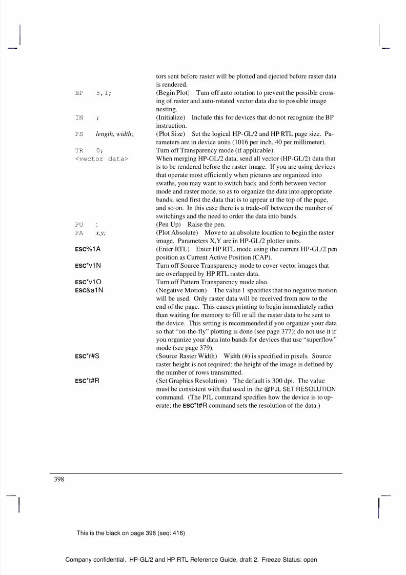
8/12/2019 HPGL2-RTL ReferenceGuide 5961-3526 540pages Sep96
http://slidepdf.com/reader/full/hpgl2-rtl-referenceguide-5961-3526-540pages-sep96 416/539
398
This is the black on page 398 (seq: 416)
Company confidential. HP-GL/2 and HP RTL Reference Guide, draft 2. Freeze Status: open
tors sent before raster will be plotted and ejected before raster data
is rendered.
BP 5,1; (Begin Plot) Turn off auto rotation to prevent the possible cross-
ing of raster and auto-rotated vector data due to possible imagenesting.
IN ; (Initialize) Include this for devices that do not recognize the BP
instruction.
PS length, width; (Plot Size) Set the logical HP-GL/2 and HP RTL page size. Pa-
rameters are in device units (1016 per inch, 40 per millimeter).
TR 0; Turn off Transparency mode (if applicable).
<vector data> When merging HP-GL/2 data, send all vector (HP-GL/2) data that
is to be rendered before the raster image. If you are using devices
that operate most efficiently when pictures are organized into
swaths, you may want to switch back and forth between vector
mode and raster mode, so as to organize the data into appropriate
bands; send first the data that is to appear at the top of the page,and so on. In this case there is a trade-off between the number of
switchings and the need to order the data into bands.
PU ; (Pen Up) Raise the pen.
PA x,y; (Plot Absolute) Move to an absolute location to begin the raster
image. Parameters X,Y are in HP-GL/2 plotter units.
%1A (Enter RTL) Enter HP RTL mode using the current HP-GL/2 pen
position as Current Active Position (CAP).
*v1N Turn off Source Transparency mode to cover vector images that
are overlapped by HP RTL raster data.
*v1O Turn off Pattern Transparency mode also.
&a1N (Negative Motion) The value 1 specifies that no negative motion
will be used. Only raster data will be received from now to the
end of the page. This causes printing to begin immediately rather
than waiting for memory to fill or all the raster data to be sent to
the device. This setting is recommended if you organize your data
so that “on-the-fly” plotting is done (see page 377); do not use it if
you organize your data into bands for devices that use “superflow”
mode (see page 379).
*r#S (Source Raster Width) Width (#) is specified in pixels. Source
raster height is not required; the height of the image is defined by
the number of rows transmitted.
*t#R (Set Graphics Resolution) The default is 300 dpi. The value
must be consistent with that used in the @PJL SET RESOLUTION
command. (The PJL command specifies how the device is to op-
erate; the *t#R command sets the resolution of the data.)
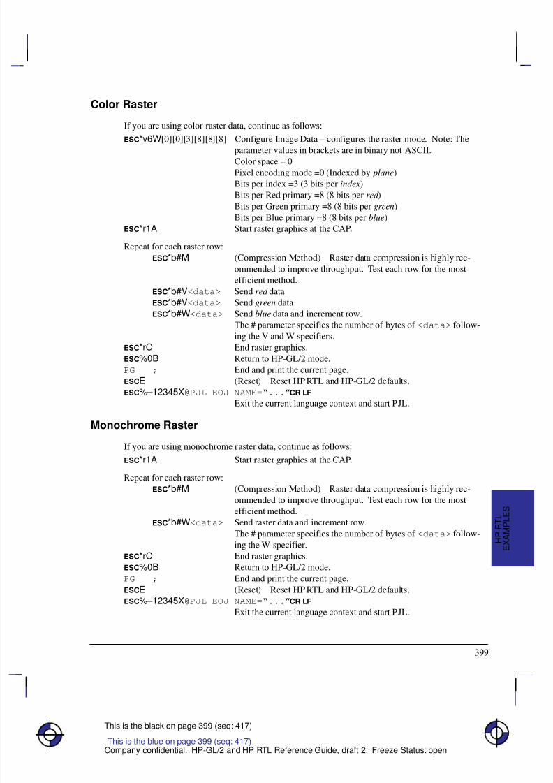
8/12/2019 HPGL2-RTL ReferenceGuide 5961-3526 540pages Sep96
http://slidepdf.com/reader/full/hpgl2-rtl-referenceguide-5961-3526-540pages-sep96 417/539
399
This is the black on page 399 (seq: 417)
Company confidential. HP-GL/2 and HP RTL Reference Guide, draft 2. Freeze Status: open
Color Raster
If you are using color raster data, continue as follows:
*v6W[0][0][3][8][8][8] Configure Image Data – configures the raster mode. Note: Theparameter values in brackets are in binary not ASCII.
Color space = 0
Pixel encoding mode =0 (Indexed by plane)
Bits per index =3 (3 bits per index)
Bits per Red primary =8 (8 bits per red )
Bits per Green primary =8 (8 bits per green)
Bits per Blue primary =8 (8 bits per blue)
*r1A Start raster graphics at the CAP.
Repeat for each raster row:
*b#M (Compression Method) Raster data compression is highly rec-
ommended to improve throughput. Test each row for the most
efficient method.
*b#V<data> Send red data
*b#V<data> Send green data
*b#W<data> Send blue data and increment row.
The # parameter specifies the number of bytes of <data> follow-
ing the V and W specifiers.
*rC End raster graphics.
%0B Return to HP-GL/2 mode.
PG ; End and print the current page.
E (Reset) Reset HP RTL and HP-GL/2 defaults.
%–12345X@PJL EOJ NAME=“...”
Exit the current language context and start PJL.
Monochrome Raster
If you are using monochrome raster data, continue as follows:
*r1A Start raster graphics at the CAP.
Repeat for each raster row:
*b#M (Compression Method) Raster data compression is highly rec-
ommended to improve throughput. Test each row for the most
efficient method.
*b#W<data> Send raster data and increment row.
The # parameter specifies the number of bytes of <data> follow-
ing the W specifier.*rC End raster graphics.
%0B Return to HP-GL/2 mode.
PG ; End and print the current page.
E (Reset) Reset HP RTL and HP-GL/2 defaults.
%–12345X@PJL EOJ NAME=“...”
Exit the current language context and start PJL.
This is the blue on page 399 (seq: 417)
E
X A M P L E S
H P R T L
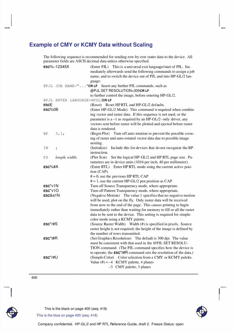
8/12/2019 HPGL2-RTL ReferenceGuide 5961-3526 540pages Sep96
http://slidepdf.com/reader/full/hpgl2-rtl-referenceguide-5961-3526-540pages-sep96 418/539
400
This is the black on page 400 (seq: 418)
Company confidential. HP-GL/2 and HP RTL Reference Guide, draft 2. Freeze Status: open
Example of CMY or KCMY Data without Scaling
The following sequence is recommended for sending row-by-row raster data to the device. Allparameter fields are ASCII decimal data unless otherwise specified.
%–12345X (Enter PJL) This is a universal exit language/start of PJL. Im-
mediately afterwards send the following commands to assign a job
name, and to switch the device out of PJL and into HP-GL/2 lan-
guage:
@PJL JOB NAME=“...” Insert any further PJL commands, such as
@PJL SET RESOLUTION=300
to further control the image, before entering HP-GL/2.
@PJL ENTER LANGUAGE=HPGL2
E (Reset) Reset HP RTL and HP-GL/2 defaults.
%0B (Enter HP-GL/2 Mode). This command is required when combin-
ing vector and raster data. If this sequence is not used, or the
parameter is a –1 as required by an HP-GL/2- only driver, any
vectors sent before raster will be plotted and ejected before raster
data is rendered.
BP 5,1; (Begin Plot) Turn off auto rotation to prevent the possible cross-
ing of raster and auto-rotated vector data due to possible image
nesting.
IN ; (Initialize) Include this for devices that do not recognize the BP
instruction.
PS length, width; (Plot Size) Set the logical HP-GL/2 and HP RTL page size. Pa-
rameters are in device units (1016 per inch, 40 per millimeter).
%#A (Enter RTL) Enter HP RTL mode using the current active posi-
tion (CAP).
# = 0, use the previous HP RTL CAP# = 1, use the current HP-GL/2 pen position as CAP
*v1N Turn off Source Transparency mode, where appropriate.
*v1O Turn off Pattern Transparency mode, where appropriate.
&a1N (Negative Motion) The value 1 specifies that no negative motion
will be used, plot on the fly. Only raster data will be received
from now to the end of the page. This causes printing to begin
immediately rather than waiting for memory to fill or all the raster
data to be sent to the device. This setting is required for simple-
color mode using a KCMY palette.
*r#S (Source Raster Width) Width (#) is specified in pixels. Source
raster height is not required; the height of the image is defined by
the number of rows transmitted.*t#R (Set Graphics Resolution) The default is 300 dpi. The value
must be consistent with that used in the @PJL SET RESOLU-
TION command. (The PJL command specifies how the device is
to operate; the *t#R command sets the resolution of the data.)
*r#U (Simple Color) Color selection from a CMY or KCMY palette.
Value (#) = –4 KCMY palette, 4 planes
–3 CMY palette, 3 planes
This is the blue on page 400 (seq: 418)
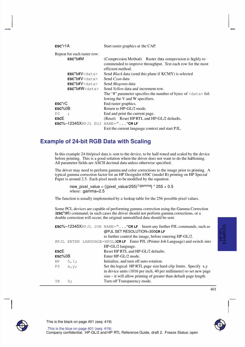
8/12/2019 HPGL2-RTL ReferenceGuide 5961-3526 540pages Sep96
http://slidepdf.com/reader/full/hpgl2-rtl-referenceguide-5961-3526-540pages-sep96 419/539
401
This is the black on page 401 (seq: 419)
Company confidential. HP-GL/2 and HP RTL Reference Guide, draft 2. Freeze Status: open
*r1A Start raster graphics at the CAP.
Repeat for each raster row:
*b#M (Compression Method) Raster data compression is highly re-commended to improve throughput. Test each row for the most
efficient method.
*b#V<data> Send Black data (send this plane if KCMY) is selected
*b#V<data> Send Cyan data
*b#V<data> Send Magenta data
*b#W<data> Send Yellow data and increment row.
The “#” parameter specifies the number of bytes of <data> fol-
lowing the V and W specifiers.
*rC End raster graphics.
%0B Return to HP-GL/2 mode.
PG ; End and print the current page.
E (Reset) Reset HP RTL and HP-GL/2 defaults.
%–12345X@PJL EOJ NAME=“...”
Exit the current language context and start PJL.
Example of 24-bit RGB Data with Scaling
In this example 24-bit/pixel data is sent to the device, to be half-toned and scaled by the devicebefore printing. This is a good solution where the driver does not want to do the halftoning.All parameter fields are ASCII decimal data unless otherwise specified.
The driver may need to perform gamma and color corrections to the image prior to printing. Atypical gamma correction factor for an HP DesignJet 650C (model B) printing on HP SpecialPaper is around 2.5. Each pixel needs to be modified by the equation:
new_pixel_value = ((pixel_value/255)1/gamma) * 255 + 0.5where: gamma=2.5
The function is usually implemented by a lookup table for the 256 possible pixel values.
Some PCL devices are capable of performing gamma correction using the Gamma Correction(*t#I) command; in such cases the driver should not perform gamma corrections, or adouble correction will occur; the original unmodified data should be sent.
%–12345X@PJL JOB NAME=“...” Insert any further PJL commands, such as
@PJL SET RESOLUTION=300
to further control the image, before entering HP-GL/2.
@PJL ENTER LANGUAGE=HPGL2
Enter PJL (Printer Job Language) and switch intoHP-GL/2 language.
E Reset HP RTL and HP-GL/2 defaults.
%0B Enter HP-GL/2 mode.
BP 5,1; Initialize, and turn off auto-rotation.
PS x,y; Set the logical HP RTL page size hard-clip limits. Specify x,y
in device units (1016 per inch, 40 per millimeter) to set new page
size – it will allow printing of greater than default page length.
TR 0; Turn off Transparency mode.
This is the blue on page 401 (seq: 419)
E
X A M P L E S
H P R T L
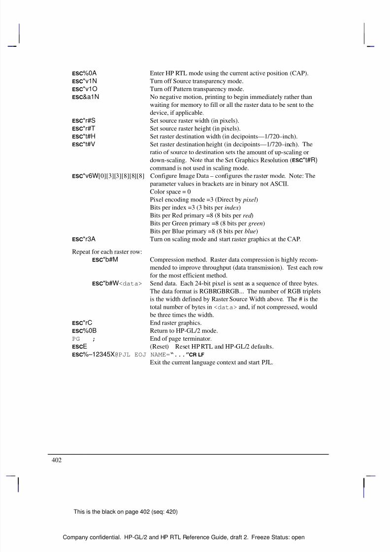
8/12/2019 HPGL2-RTL ReferenceGuide 5961-3526 540pages Sep96
http://slidepdf.com/reader/full/hpgl2-rtl-referenceguide-5961-3526-540pages-sep96 420/539
402
This is the black on page 402 (seq: 420)
Company confidential. HP-GL/2 and HP RTL Reference Guide, draft 2. Freeze Status: open
%0A Enter HP RTL mode using the current active position (CAP).
*v1N Turn off Source transparency mode.
*v1O Turn off Pattern transparency mode.
&a1N No negative motion, printing to begin immediately rather thanwaiting for memory to fill or all the raster data to be sent to the
device, if applicable.
*r#S Set source raster width (in pixels).
*r#T Set source raster height (in pixels).
*t#H Set raster destination width (in decipoints—1/720–inch).
*t#V Set raster destination height (in decipoints—1/720–inch). The
ratio of source to destination sets the amount of up-scaling or
down-scaling. Note that the Set Graphics Resolution (*t#R)
command is not used in scaling mode.
*v6W[0][3][3][8][8][8] Configure Image Data – configures the raster mode. Note: The
parameter values in brackets are in binary not ASCII.
Color space = 0Pixel encoding mode =3 (Direct by pixel)
Bits per index =3 (3 bits per index)
Bits per Red primary =8 (8 bits per red )
Bits per Green primary =8 (8 bits per green)
Bits per Blue primary =8 (8 bits per blue)
*r3A Turn on scaling mode and start raster graphics at the CAP.
Repeat for each raster row:
*b#M Compression method. Raster data compression is highly recom-
mended to improve throughput (data transmission). Test each row
for the most efficient method.
*b#W<data> Send data. Each 24-bit pixel is sent as a sequence of three bytes.
The data format is RGBRGBRGB... The number of RGB tripletsis the width defined by Raster Source Width above. The # is the
total number of bytes in <data> and, if not compressed, would
be three times the width.
*rC End raster graphics.
%0B Return to HP-GL/2 mode.
PG ; End of page terminator.
E (Reset) Reset HP RTL and HP-GL/2 defaults.
%–12345X@PJL EOJ NAME=“...”
Exit the current language context and start PJL.
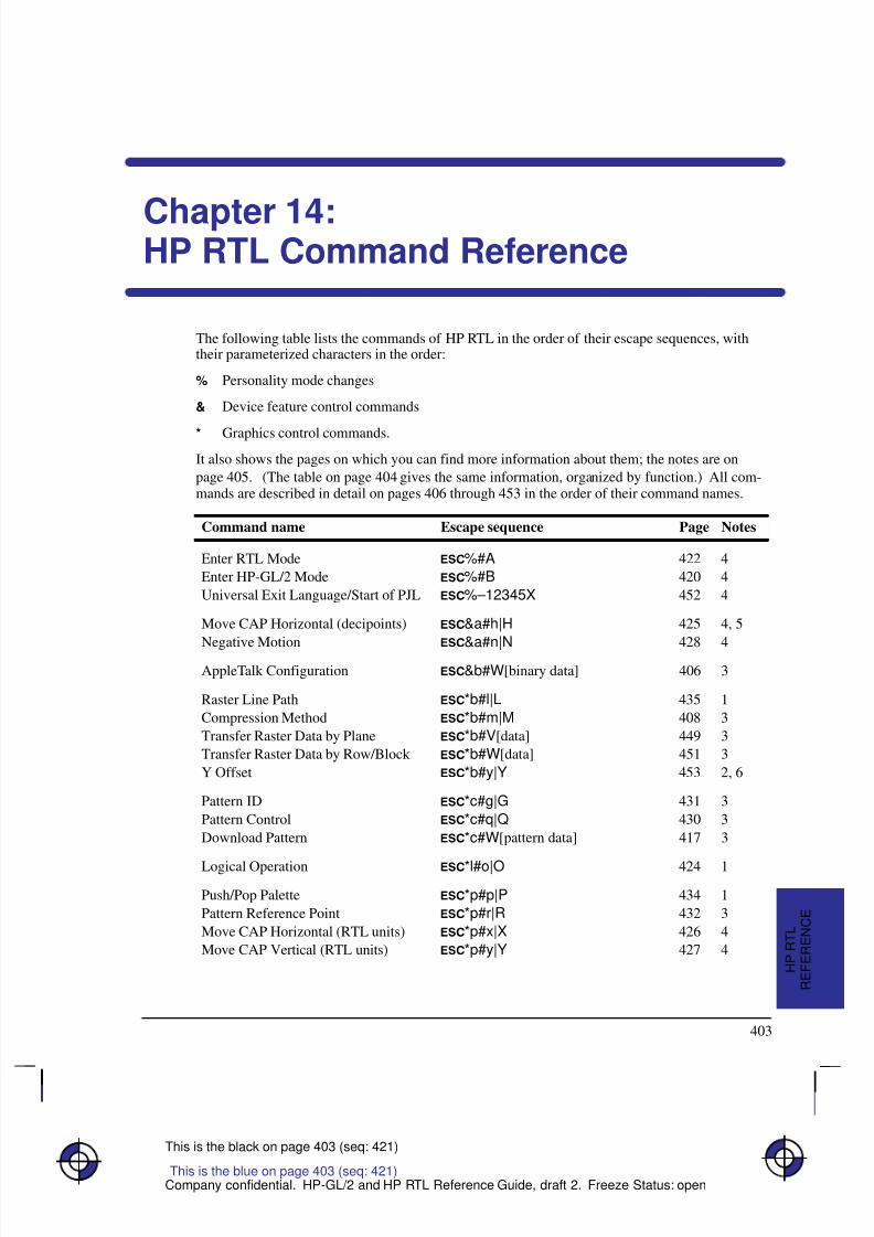
8/12/2019 HPGL2-RTL ReferenceGuide 5961-3526 540pages Sep96
http://slidepdf.com/reader/full/hpgl2-rtl-referenceguide-5961-3526-540pages-sep96 421/539
403
This is the black on page 403 (seq: 421)
Company confidential. HP-GL/2 and HP RTL Reference Guide, draft 2. Freeze Status: open
Chapter 14:HP RTL Command Reference
The following table lists the commands of HP RTL in the order of their escape sequences, withtheir parameterized characters in the order:
% Personality mode changes
& Device feature control commands
* Graphics control commands.
It also shows the pages on which you can find more information about them; the notes are on
page 405. (The table on page 404 gives the same information, organized by function.) All com-mands are described in detail on pages 406 through 453 in the order of their command names.
Command name Escape sequence Page Notes
Enter RTL Mode %#A 422 4
Enter HP-GL/2 Mode %#B 420 4
Universal Exit Language/Start of PJL %–12345X 452 4
Move CAP Horizontal (decipoints) &a#h|H 425 4, 5
Negative Motion &a#n|N 428 4
AppleTalk Configuration &b#W[binary data] 406 3
Raster Line Path *b#l|L 435 1
Compression Method *b#m|M 408 3
Transfer Raster Data by Plane *b#V[data] 449 3
Transfer Raster Data by Row/Block *b#W[data] 451 3
Y Offset *b#y|Y 453 2, 6
Pattern ID *c#g|G 431 3
Pattern Control *c#q|Q 430 3
Download Pattern *c#W[pattern data] 417 3
Logical Operation *l#o|O 424 1
Push/Pop Palette *p#p|P 434 1
Pattern Reference Point *p#r|R 432 3
Move CAP Horizontal (RTL units) *p#x|X 426 4
Move CAP Vertical (RTL units) *p#y|Y 427 4
This is the blue on page 403 (seq: 421)
R E F E R E N C E
H P R T L
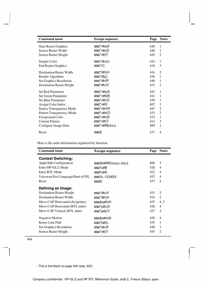
8/12/2019 HPGL2-RTL ReferenceGuide 5961-3526 540pages Sep96
http://slidepdf.com/reader/full/hpgl2-rtl-referenceguide-5961-3526-540pages-sep96 422/539
404
This is the black on page 404 (seq: 422)
Company confidential. HP-GL/2 and HP RTL Reference Guide, draft 2. Freeze Status: open
Command name NotesPageEscape sequence
Start Raster Graphics *r#a|A 448 1
Source Raster Width *r#s|S 446 1Source Raster Height *r#t|T 445 2
Simple Color *r#u|U 443 1
End Raster Graphics *rC 419 3
Destination Raster Width *t#h|H 416 2
Render Algorithm *t#j|J 436 1
Set Graphics Resolution *t#r|R 440 1
Destination Raster Height *t#v|V 415 2
Set Red Parameter *v#a|A 442 1
Set Green Parameter *v#b|B 441 1
Set Blue Parameter *v#c|C 439 1Assign Color Index *v#i|I 407 1
Source Transparency Mode *v#n|N 447 3
Pattern Transparency Mode *v#o|O 433 3
Foreground Color *v#s|S 423 1
Current Pattern *v#t|T 414 3
Configure Image Data *v#W[data] 409 1
Reset E 437 4
Here is the same information organized by function:
Command name Escape sequence Page Notes
Context Switching:AppleTalk Configuration &b#W[binary data] 406 3
Enter HP-GL/2 Mode %#B 420 4
Enter RTL Mode %#A 422 4
Universal Exit Language/Start of PJL %–12345X 452 4
Reset E 437 4
Defining an Image:Destination Raster Height *t#v|V 415 2
Destination Raster Width *t#h|H 416 2
Move CAP Horizontal (decipoints) &a#h|H 425 4, 5Move CAP Horizontal (RTL units) *p#x|X 426 4
Move CAP Vertical (RTL units) *p#y|Y 427 4
Negative Motion &a#n|N 428 4
Raster Line Path *b#l|L 435 1
Set Graphics Resolution *t#r|R 440 1
Source Raster Height *r#t|T 445 2
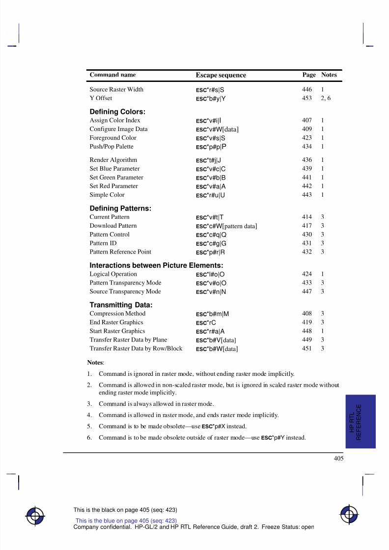
8/12/2019 HPGL2-RTL ReferenceGuide 5961-3526 540pages Sep96
http://slidepdf.com/reader/full/hpgl2-rtl-referenceguide-5961-3526-540pages-sep96 423/539
405
This is the black on page 405 (seq: 423)
Company confidential. HP-GL/2 and HP RTL Reference Guide, draft 2. Freeze Status: open
Command name NotesPageEscape sequence
Source Raster Width *r#s|S 446 1
Y Offset *b#y|Y 453 2, 6
Defining Colors:Assign Color Index *v#i|I 407 1
Configure Image Data *v#W[data] 409 1
Foreground Color *v#s|S 423 1
Push/Pop Palette *p#p|P 434 1
Render Algorithm *t#j|J 436 1
Set Blue Parameter *v#c|C 439 1
Set Green Parameter *v#b|B 441 1
Set Red Parameter *v#a|A 442 1
Simple Color *r#u|U 443 1
Defining Patterns:Current Pattern *v#t|T 414 3
Download Pattern *c#W[pattern data] 417 3
Pattern Control *c#q|Q 430 3
Pattern ID *c#g|G 431 3
Pattern Reference Point *p#r|R 432 3
Interactions between Picture Elements:Logical Operation *l#o|O 424 1
Pattern Transparency Mode *v#o|O 433 3
Source Transparency Mode *v#n|N 447 3
Transmitting Data:Compression Method *b#m|M 408 3
End Raster Graphics *rC 419 3
Start Raster Graphics *r#a|A 448 1
Transfer Raster Data by Plane *b#V[data] 449 3
Transfer Raster Data by Row/Block *b#W[data] 451 3
Notes:
1. Command is ignored in raster mode, without ending raster mode implicitly.
2. Command is allowed in non-scaled raster mode, but is ignored in scaled raster mode withoutending raster mode implicitly.
3. Command is always allowed in raster mode.
4. Command is allowed in raster mode, and ends raster mode implicitly.
5. Command is to be made obsolete—use *p#X instead.
6. Command is to be made obsolete outside of raster mode—use *p#Y instead.
This is the blue on page 405 (seq: 423)
R E F E R E N C E
H P R T L
8/12/2019 HPGL2-RTL ReferenceGuide 5961-3526 540pages Sep96
http://slidepdf.com/reader/full/hpgl2-rtl-referenceguide-5961-3526-540pages-sep96 424/539
406
This is the black on page 406 (seq: 424)
Company confidential. HP-GL/2 and HP RTL Reference Guide, draft 2. Freeze Status: open
AppleTalk Configuration
&b#W[data]
Purpose
This command provides communication with an AppleTalk driver. It is not used in DOS.
# Parameter and Termination Character
# Number of bytes of ASCII character data. The default is 0.
Range: 0 through 32 767. Other values cause the command to be ignored.
This command cannot be combined with others that follow. The uppercase “W” terminator mustbe used with this command.
Use
This command can be used to provide a job name, to rename the printer for identification on theAppleTalk network, or to provide a printer type, such as HP-GL/2 or PostScript. The data fieldconsists of a keyword (JOB, RENAME, or TYPE), a space, and a value; the value is terminatedeither by a null () character or by the expiration of the count of data bytes. The followingbinary sequences are recognized:
JOB <job name>
This renames the current job; up to 127 characters can be specified; there is no default
job name.
RENAME <new name>
This changes the name field of the device’s AppleTalk Network Identifier (Name Bind-ing Protocol name field); between 1 and 31 characters can be specified; all characters arevalid except a null () which terminates the device name, “@”, “:”, “*”, “=”, “”(hexadecimal C5) and hexadecimal FF. (If an invalid character appears, the command isignored.)
TYPE <type name>
This changes the type field of the device’s AppleTalk Network Identifier (Name BindingProtocol type field); between 1 and 31 characters can be specified; all characters are val-id except a null () which terminates the device type, “@”, “:”, “*”, “=”, “”
(hexadecimal C5) and hexadecimal FF. (If an invalid character appears, the command isignored.) Type changes occur only after the present job is completed.
This is the blue on page 406 (seq: 424)

8/12/2019 HPGL2-RTL ReferenceGuide 5961-3526 540pages Sep96
http://slidepdf.com/reader/full/hpgl2-rtl-referenceguide-5961-3526-540pages-sep96 425/539
407
This is the black on page 407 (seq: 425)
Company confidential. HP-GL/2 and HP RTL Reference Guide, draft 2. Freeze Status: open
Assign Color Index
*v#i|I
Purpose
This command assigns the currently specified red, green, and blue (RGB) parameters to the desig-nated index number. RGB parameters are specified by the Set Red Parameter (*v#A), SetGreen Parameter (*v#B), and Set Blue Parameter (*v#C) commands.
# Parameter
# Index number. The default is 0.
Range: 0 to (2n – 1) where “n” is the number of bits per index (planes per row) speci-fied in the Set Number of Bits per Index byte of the Configure Image Data command.(Assign Color Index with an out-of-range value resets the RGB parameters to 0, but isotherwise ignored.)
Use
The parameters set by Set Red/Green/Blue Parameter are reset to 0 after executing this command.
This command is ignored during raster mode.
This is the blue on page 407 (seq: 425)
R E F E R E N C E
H P R T L
8/12/2019 HPGL2-RTL ReferenceGuide 5961-3526 540pages Sep96
http://slidepdf.com/reader/full/hpgl2-rtl-referenceguide-5961-3526-540pages-sep96 426/539
408
This is the black on page 408 (seq: 426)
Company confidential. HP-GL/2 and HP RTL Reference Guide, draft 2. Freeze Status: open
Compression Method
*b#m|M
Purpose
This command determines how raster data is interpreted in the Transfer Raster Data by Plane andTransfer Raster Data by Row/Block (*b#V or *b#W) commands. The compressionmethod stays in effect until explicitly changed by another Compression Method command or untildefaulted by an explicit or implicit End Raster Graphics (*rC) or a machine Reset (E).
# Parameter
# The following values are allowed. The default is 0.0 unencoded (row-based)
1 run-length encoding (row-based)
2 Tagged Image File Format (TIFF) revision 4.0 “Packbits” encoding (row-based)
3 seed-row or delta–row encoding (row-based)
4 unencoded (block-based)
5 adaptive encoding (block-based)
6 CCITT Group 3 one-dimensional encoding (block-based)
7 CCITT Group 3 two-dimensional encoding (block-based)
8 CCITT Group 4 encoding (block-based)
Range: 0 through 8 (out-of-range or unimplemented values default to 0).
Use
See Compressing Data on page 380 for a description of the data compression methods. The fol-lowing is a summary of the format of data used in methods 1, 2, 3, and 5:
1 { <repetition-count> <literal data-byte to be repeated> }...
2 { { <0 to 127> <1 to 128 literal data-bytes> } |{ <–1 to –127> <data-byte to be repeated 1 to 127 times> } |{ –128 (ignored)} }...
3 { <no. of replacement bytes (000 to 111 = 1 to 8; 3 bits)
+ offset from current byte (5 bits)>[<additional offset byte(s)>] <1 to 8 replacement bytes> } ...
5 { <command byte> <no. of bytes/row (2-byte field)><raster data> } ...
Command byte = 0 Unencoded1 Run-Length Encoding2 Tagged Image File Format (TIFF)3 Delta Row4 Empty Row5 Duplicate Row
This is the blue on page 408 (seq: 426)
8/12/2019 HPGL2-RTL ReferenceGuide 5961-3526 540pages Sep96
http://slidepdf.com/reader/full/hpgl2-rtl-referenceguide-5961-3526-540pages-sep96 427/539
409
This is the black on page 409 (seq: 427)
Company confidential. HP-GL/2 and HP RTL Reference Guide, draft 2. Freeze Status: open
Configure Image Data
*v#W[data]
Purpose
This command configures the device for color imaging by performing the following actions:
Specifies the number of bits per index and defaults the color palette accordingly.
Sets the color space.
Sets the pixel encoding mode.
Sets the number of bits per primary for red, green, and blue.
Sets the white- and black-reference values for red, green, and blue.
# Parameter and Termination Character
# There is no default. The parameter is defined as follows:
6 Perform the actions listed above. Set the white and black reference values based onthe number of bits per primary red, green, and blue. In this case, the black referenceis always set to 0, and the white reference is set to 2number of bits per primary – 1. Use 8bits per primary to retain the default color range of 0 through 255 (28 – 1 = 255).
18 Perform the actions listed above. Set the white and black reference values to theexplicit settings in the last 12 bytes of the data.
Range: 6, 18. (Other values less than 18 cause the command to be ignored. Valuesgreater than 18 are valid, but only the first 18 bytes are used.)
This command cannot be combined with others that follow. The uppercase “W” terminator mustbe used with this command.
Use
This command is ignored in raster mode.
The data field is interpreted as shown in the table on the next page. Bytes 0 through 5 are interpreted assix 1-byte unsigned binary integers; bytes 6 through 17 are interpreted as six 2-byte signed binaryintegers.
The sections Encoding Colors on page 356 and Defining the HP RTL Palette on page 356 de-scribe the concepts behind the Configure Image Data command. Refer to this section for moreinformation on data planes, the color palette, indexes, and raster modes.
This is the blue on page 409 (seq: 427)
R E F E R E N C E
H P R T L
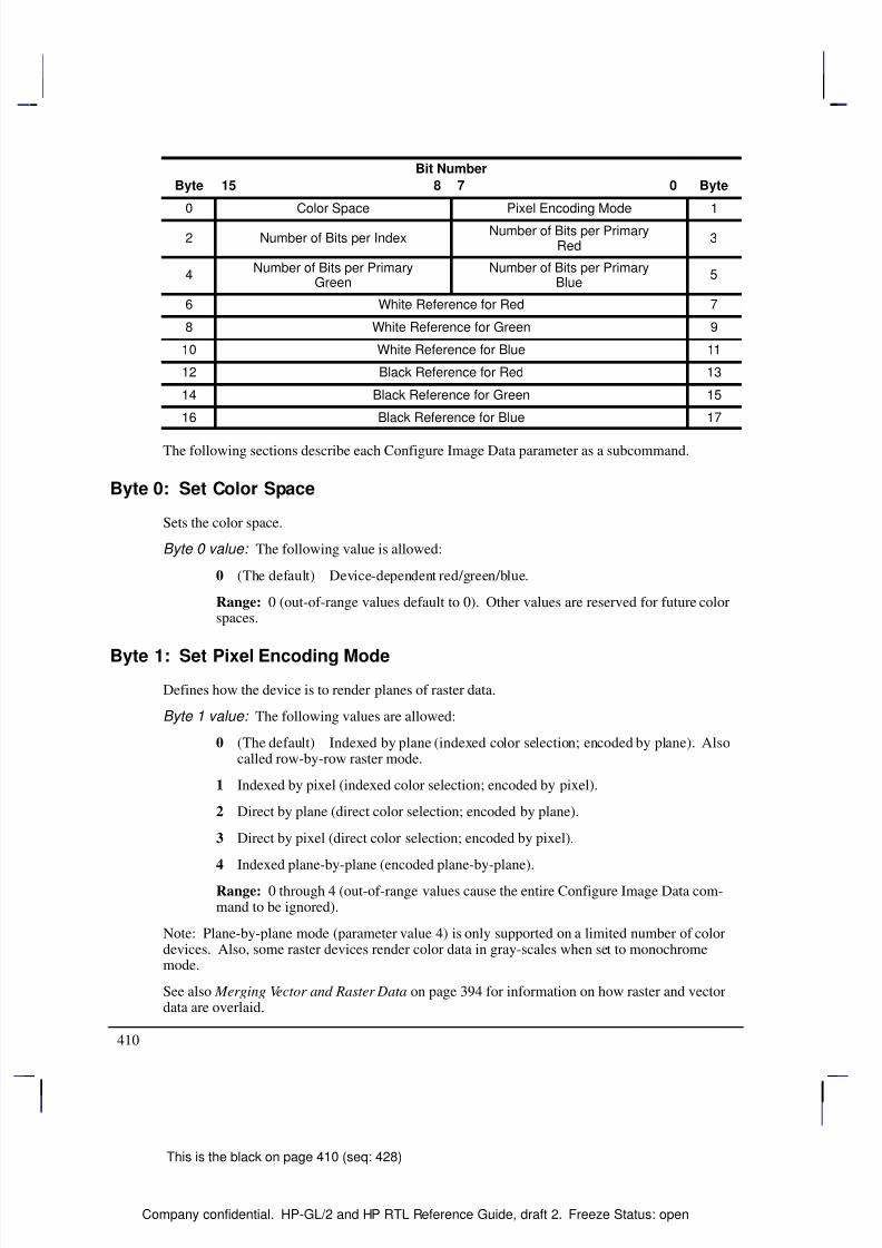
8/12/2019 HPGL2-RTL ReferenceGuide 5961-3526 540pages Sep96
http://slidepdf.com/reader/full/hpgl2-rtl-referenceguide-5961-3526-540pages-sep96 428/539
410
This is the black on page 410 (seq: 428)
Company confidential. HP-GL/2 and HP RTL Reference Guide, draft 2. Freeze Status: open
Bit Number
Byte 15 8 7 0 Byte
0 Color Space Pixel Encoding Mode 1
2 Number of Bits per IndexNumber of Bits per Primary
Red3
4Number of Bits per Primary
GreenNumber of Bits per Primary
Blue5
6 White Reference for Red 7
8 White Reference for Green 9
10 White Reference for Blue 11
12 Black Reference for Red 13
14 Black Reference for Green 15
16 Black Reference for Blue 17
The following sections describe each Configure Image Data parameter as a subcommand.
Byte 0: Set Color Space
Sets the color space.
Byte 0 value: The following value is allowed:
0 (The default) Device-dependent red/green/blue.
Range: 0 (out-of-range values default to 0). Other values are reserved for future colorspaces.
Byte 1: Set Pixel Encoding Mode
Defines how the device is to render planes of raster data.
Byte 1 value: The following values are allowed:
0 (The default) Indexed by plane (indexed color selection; encoded by plane). Alsocalled row-by-row raster mode.
1 Indexed by pixel (indexed color selection; encoded by pixel).
2 Direct by plane (direct color selection; encoded by plane).
3 Direct by pixel (direct color selection; encoded by pixel).
4 Indexed plane-by-plane (encoded plane-by-plane).
Range: 0 through 4 (out-of-range values cause the entire Configure Image Data com-mand to be ignored).
Note: Plane-by-plane mode (parameter value 4) is only supported on a limited number of colordevices. Also, some raster devices render color data in gray-scales when set to monochromemode.
See also Merging Vector and Raster Data on page 394 for information on how raster and vectordata are overlaid.
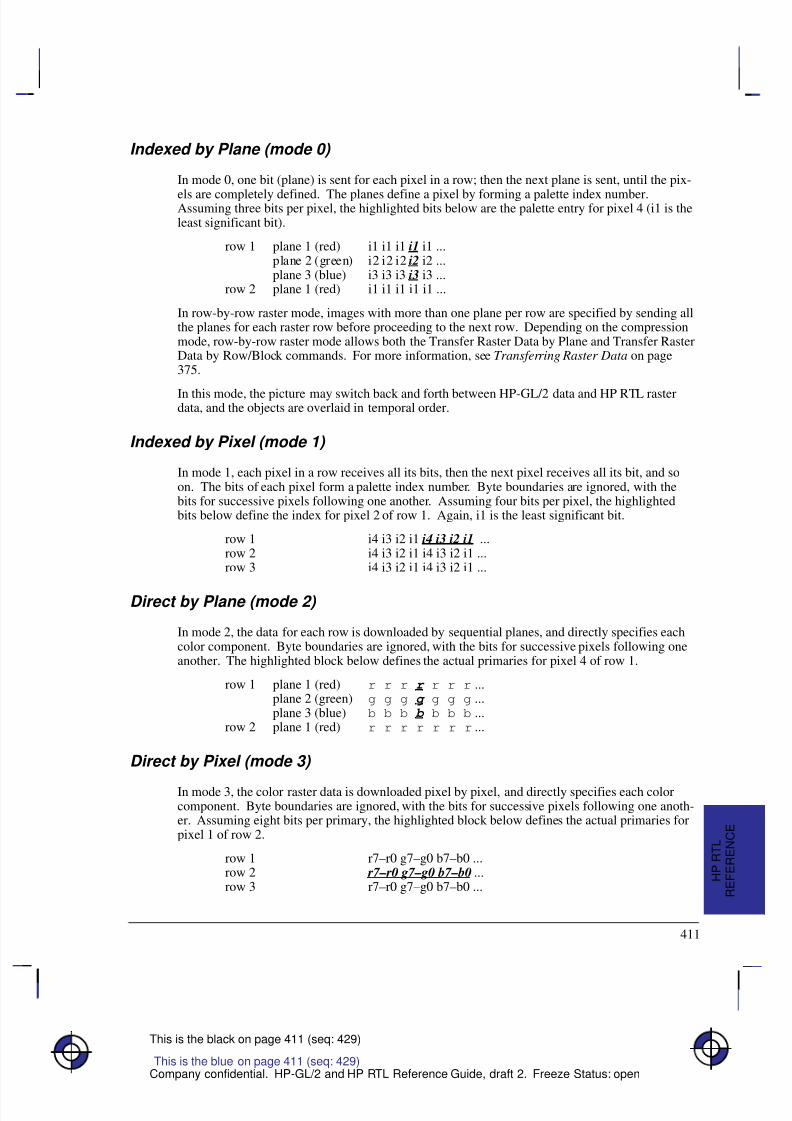
8/12/2019 HPGL2-RTL ReferenceGuide 5961-3526 540pages Sep96
http://slidepdf.com/reader/full/hpgl2-rtl-referenceguide-5961-3526-540pages-sep96 429/539
411
This is the black on page 411 (seq: 429)
Company confidential. HP-GL/2 and HP RTL Reference Guide, draft 2. Freeze Status: open
Indexed by Plane (mode 0)
In mode 0, one bit (plane) is sent for each pixel in a row; then the next plane is sent, until the pix-
els are completely defined. The planes define a pixel by forming a palette index number.Assuming three bits per pixel, the highlighted bits below are the palette entry for pixel 4 (i1 is theleast significant bit).
row 1 plane 1 (red) i1 i1 i1 i1 i1 ...plane 2 (green) i2 i2 i2 i2 i2 ...plane 3 (blue) i3 i3 i3 i3 i3 ...
row 2 plane 1 (red) i1 i1 i1 i1 i1 ...
In row-by-row raster mode, images with more than one plane per row are specified by sending allthe planes for each raster row before proceeding to the next row. Depending on the compressionmode, row-by-row raster mode allows both the Transfer Raster Data by Plane and Transfer RasterData by Row/Block commands. For more information, see Transferring Raster Data on page375.
In this mode, the picture may switch back and forth between HP-GL/2 data and HP RTL rasterdata, and the objects are overlaid in temporal order.
Indexed by Pixel (mode 1)
In mode 1, each pixel in a row receives all its bits, then the next pixel receives all its bit, and soon. The bits of each pixel form a palette index number. Byte boundaries are ignored, with thebits for successive pixels following one another. Assuming four bits per pixel, the highlightedbits below define the index for pixel 2 of row 1. Again, i1 is the least significant bit.
row 1 i4 i3 i2 i1 i4 i3 i2 i1 ...row 2 i4 i3 i2 i1 i4 i3 i2 i1 ...row 3 i4 i3 i2 i1 i4 i3 i2 i1 ...
Direct by Plane (mode 2)
In mode 2, the data for each row is downloaded by sequential planes, and directly specifies eachcolor component. Byte boundaries are ignored, with the bits for successive pixels following oneanother. The highlighted block below defines the actual primaries for pixel 4 of row 1.
row 1 plane 1 (red) r r r r r r r ...plane 2 (green) g g g g g g g ...plane 3 (blue) b b b b b b b ...
row 2 plane 1 (red) r r r r r r r ...
Direct by Pixel (mode 3)
In mode 3, the color raster data is downloaded pixel by pixel, and directly specifies each colorcomponent. Byte boundaries are ignored, with the bits for successive pixels following one anoth-er. Assuming eight bits per primary, the highlighted block below defines the actual primaries forpixel 1 of row 2.
row 1 r7–r0 g7–g0 b7–b0 ...row 2 r7–r0 g7–g0 b7–b0 ...row 3 r7–r0 g7–g0 b7–b0 ...
This is the blue on page 411 (seq: 429)
R E F E R E N C E
H P R T L
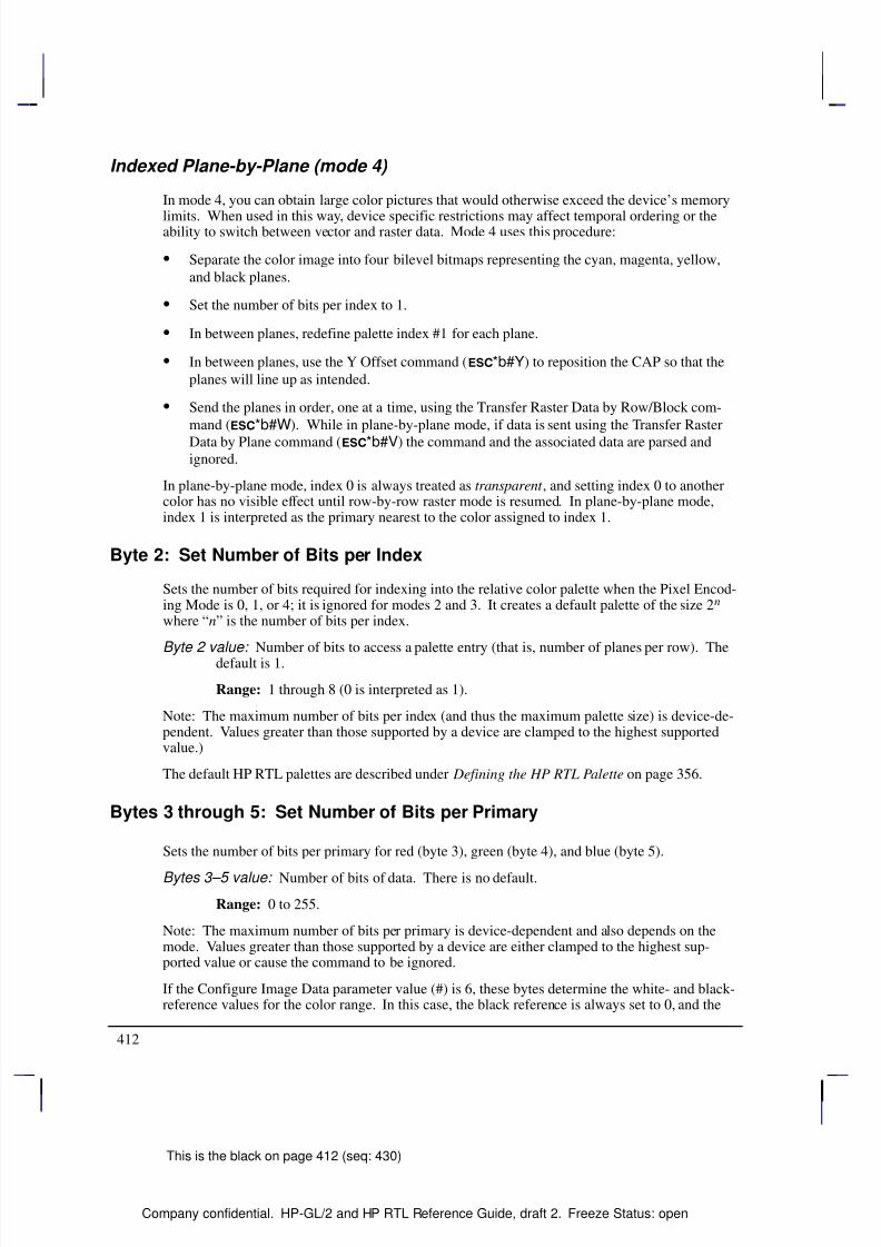
8/12/2019 HPGL2-RTL ReferenceGuide 5961-3526 540pages Sep96
http://slidepdf.com/reader/full/hpgl2-rtl-referenceguide-5961-3526-540pages-sep96 430/539
412
This is the black on page 412 (seq: 430)
Company confidential. HP-GL/2 and HP RTL Reference Guide, draft 2. Freeze Status: open
Indexed Plane-by-Plane (mode 4)
In mode 4, you can obtain large color pictures that would otherwise exceed the device’s memory
limits. When used in this way, device specific restrictions may affect temporal ordering or theability to switch between vector and raster data. Mode 4 uses this procedure:
Separate the color image into four bilevel bitmaps representing the cyan, magenta, yellow,
and black planes.
Set the number of bits per index to 1.
In between planes, redefine palette index #1 for each plane.
In between planes, use the Y Offset command (*b#Y) to reposition the CAP so that the
planes will line up as intended.
Send the planes in order, one at a time, using the Transfer Raster Data by Row/Block com-
mand (*b#W). While in plane-by-plane mode, if data is sent using the Transfer Raster
Data by Plane command (*b#V) the command and the associated data are parsed andignored.
In plane-by-plane mode, index 0 is always treated as transparent , and setting index 0 to anothercolor has no visible effect until row-by-row raster mode is resumed. In plane-by-plane mode,index 1 is interpreted as the primary nearest to the color assigned to index 1.
Byte 2: Set Number of Bits per Index
Sets the number of bits required for indexing into the relative color palette when the Pixel Encod-ing Mode is 0, 1, or 4; it is ignored for modes 2 and 3. It creates a default palette of the size 2n
where “n” is the number of bits per index.
Byte 2 value: Number of bits to access a palette entry (that is, number of planes per row). Thedefault is 1.
Range: 1 through 8 (0 is interpreted as 1).
Note: The maximum number of bits per index (and thus the maximum palette size) is device-de-pendent. Values greater than those supported by a device are clamped to the highest supportedvalue.)
The default HP RTL palettes are described under Defining the HP RTL Palette on page 356.
Bytes 3 through 5: Set Number of Bits per Primary
Sets the number of bits per primary for red (byte 3), green (byte 4), and blue (byte 5).
Bytes 3–5 value: Number of bits of data. There is no default.
Range: 0 to 255.
Note: The maximum number of bits per primary is device-dependent and also depends on themode. Values greater than those supported by a device are either clamped to the highest sup-ported value or cause the command to be ignored.
If the Configure Image Data parameter value (#) is 6, these bytes determine the white- and black-reference values for the color range. In this case, the black reference is always set to 0, and the
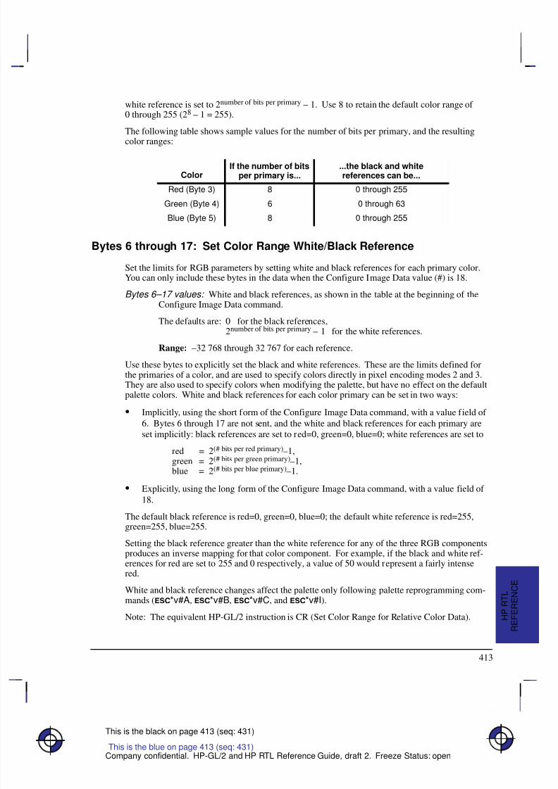
8/12/2019 HPGL2-RTL ReferenceGuide 5961-3526 540pages Sep96
http://slidepdf.com/reader/full/hpgl2-rtl-referenceguide-5961-3526-540pages-sep96 431/539
413
This is the black on page 413 (seq: 431)
Company confidential. HP-GL/2 and HP RTL Reference Guide, draft 2. Freeze Status: open
white reference is set to 2number of bits per primary – 1. Use 8 to retain the default color range of 0 through 255 (28 – 1 = 255).
The following table shows sample values for the number of bits per primary, and the resultingcolor ranges:
ColorIf the number of bits
per primary is......the black and whitereferences can be...
Red (Byte 3) 8 0 through 255
Green (Byte 4) 6 0 through 63
Blue (Byte 5) 8 0 through 255
Bytes 6 through 17: Set Color Range White/Black Reference
Set the limits for RGB parameters by setting white and black references for each primary color.
You can only include these bytes in the data when the Configure Image Data value (#) is 18.
Bytes 6–17 values: White and black references, as shown in the table at the beginning of theConfigure Image Data command.
The defaults are: 0 for the black references,2number of bits per primary – 1 for the white references.
Range: –32 768 through 32 767 for each reference.
Use these bytes to explicitly set the black and white references. These are the limits defined forthe primaries of a color, and are used to specify colors directly in pixel encoding modes 2 and 3.They are also used to specify colors when modifying the palette, but have no effect on the defaultpalette colors. White and black references for each color primary can be set in two ways:
Implicitly, using the short form of the Configure Image Data command, with a value field of 6. Bytes 6 through 17 are not sent, and the white and black references for each primary areset implicitly: black references are set to red=0, green=0, blue=0; white references are set to
red = 2(# bits per red primary)–1,green = 2(# bits per green primary)–1,blue = 2(# bits per blue primary)–1.
Explicitly, using the long form of the Configure Image Data command, with a value field of
18.
The default black reference is red=0, green=0, blue=0; the default white reference is red=255,green=255, blue=255.
Setting the black reference greater than the white reference for any of the three RGB components
produces an inverse mapping for that color component. For example, if the black and white ref-erences for red are set to 255 and 0 respectively, a value of 50 would represent a fairly intensered.
White and black reference changes affect the palette only following palette reprogramming com-mands (*v#A, *v#B, *v#C, and *v#I).
Note: The equivalent HP-GL/2 instruction is CR (Set Color Range for Relative Color Data).
This is the blue on page 413 (seq: 431)
R E F E R E N C E
H P R T L
8/12/2019 HPGL2-RTL ReferenceGuide 5961-3526 540pages Sep96
http://slidepdf.com/reader/full/hpgl2-rtl-referenceguide-5961-3526-540pages-sep96 432/539
414
This is the black on page 414 (seq: 432)
Company confidential. HP-GL/2 and HP RTL Reference Guide, draft 2. Freeze Status: open
Current Pattern
*v#t|T
Purpose
This command selects the current pattern type for raster images.
# Parameter
# The following values are allowed. The default is 0.
0 Solid black or foreground color.
1 Solid white.
2 HP-defined shading pattern.
3 HP-defined hatched pattern.
4 User-defined pattern.
Range: 0 to 4.
Use
Values of 2, 3, and 4 activate the “current pattern”, which is the one defined by Pattern ID(*c#G), see page 431. The current pattern remains active even if Pattern ID is subsequentlychanged, that is, until a new Current Pattern command is issued.
This command is ignored during raster mode.
This is the blue on page 414 (seq: 432)

8/12/2019 HPGL2-RTL ReferenceGuide 5961-3526 540pages Sep96
http://slidepdf.com/reader/full/hpgl2-rtl-referenceguide-5961-3526-540pages-sep96 433/539
415
This is the black on page 415 (seq: 433)
Company confidential. HP-GL/2 and HP RTL Reference Guide, draft 2. Freeze Status: open
Destination Raster Height
*t#v|V
Purpose
This command defines the height in decipoints (1/720 inch) of the destination raster image de-noted by subsequent Start Raster Graphics (*r#A) commands with the scale mode on(parameter value 2 or 3).
# Parameter
# Height in decipoints. There is no default.
Range: 0 through 65 535 (out-of-range values are clamped).
Zero or absent values default destination raster height to a value in which isotropic scaling ismaintained.
Use
If the specified destination height exceeds the logical page size, the scale factor is maintained andthe image is clipped at the top or bottom boundary of the logical page, depending on the RasterLine Path (*b#L).
This command is ignored during raster scaling mode.
See also Scaling Raster Images on page 345.
This is the blue on page 415 (seq: 433)
R E F E R E N C E
H P R T L
8/12/2019 HPGL2-RTL ReferenceGuide 5961-3526 540pages Sep96
http://slidepdf.com/reader/full/hpgl2-rtl-referenceguide-5961-3526-540pages-sep96 434/539
416
This is the black on page 416 (seq: 434)
Company confidential. HP-GL/2 and HP RTL Reference Guide, draft 2. Freeze Status: open
Destination Raster Width
*t#h|H
Purpose
This command defines the width in decipoints (1/720 inch) of the destination raster image de-noted by subsequent Start Raster Graphics (*r#A) commands with scale mode on (parametervalue 2 or 3).
# Parameter
# Width in decipoints. There is no default.
Range: 0 through 65535 (out-of-range values are clamped).
Zero or absent values default destination raster width to a value in which isotropic scaling ismaintained.
Use
If the specified destination width exceeds the logical page size, the scale factor is maintained andthe image is clipped at the right boundary of the logical page.
This command is ignored during raster scaling mode.
See also Scaling Raster Images on page 24.
This is the blue on page 416 (seq: 434)
8/12/2019 HPGL2-RTL ReferenceGuide 5961-3526 540pages Sep96
http://slidepdf.com/reader/full/hpgl2-rtl-referenceguide-5961-3526-540pages-sep96 435/539
417
This is the black on page 417 (seq: 435)
Company confidential. HP-GL/2 and HP RTL Reference Guide, draft 2. Freeze Status: open
Download Pattern
*c#W[pattern data]
Purpose
This command loads user-defined pattern data.
# Parameter and Termination Character
# The number of bytes of pattern data. The default is 0.
Range: 0 to 2 147 483 647 (231 – 1).
This command cannot be combined with others that follow. The uppercase “W” terminator mustbe used with this command.
Use
Loaded patterns may be loaded by their ID number, deleted, and made temporary or permanent.The pattern being loaded is assigned the current value of the Pattern ID (*c#G). Any patternthat already has this ID is deleted before the new pattern is loaded. If the current pattern, speci-fied by the last Pattern ID command, is deleted, the current pattern reverts to solid black orforeground color.
Colors in user-defined patterns are rendered as indexes into the current palette. A color patternthat uses non-primary colors (colors other than black, white, red, green, blue, cyan, magenta, oryellow) may interact with dithering, producing unpredictable results.
For efficient use of memory, the defined pattern size should be no larger than the minimum neces-sary to make the pattern unique.
The byte-aligned binary data field is shown on the next page. Missing data is assumed to be zero;excess or invalid data is discarded. Three formats are available: 0, 1, and 20.
Format byte: The following pattern formats are supported:
0 1 bit per pixel: black and white, or foreground color and white.These patterns have one bit per pixel; a 1-bit indicates black or the foreground col-or; a 0-bit indicates white or transparent (depending on the source and patterntransparency modes). A 0-bit cannot be colored.
1 1 or 8 bits per pixel. These patterns use the current palette; data is sent pixel by
pixel, and the pixel encoding byte determines the number of bits defining a pixel.
20 Resolution-specified pattern; 1 bit per pixel, as for Format 0; the pixel-encodingbyte must be 1.
This is the blue on page 417 (seq: 435)
R E F E R E N C E
H P R T L
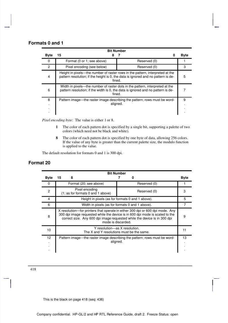
8/12/2019 HPGL2-RTL ReferenceGuide 5961-3526 540pages Sep96
http://slidepdf.com/reader/full/hpgl2-rtl-referenceguide-5961-3526-540pages-sep96 436/539
418
This is the black on page 418 (seq: 436)
Company confidential. HP-GL/2 and HP RTL Reference Guide, draft 2. Freeze Status: open
Formats 0 and 1
Bit Number
Byte 15 8 7 0 Byte0 Format (0 or 1; see above) Reserved (0) 1
2 Pixel encoding (see below) Reserved (0) 3
4Height in pixels—the number of raster rows in the pattern, interpreted at thepattern resolution; if the height is 0, the data is ignored and no pattern is de-
fined.5
6Width in pixels—the number of raster dots in the pattern, interpreted at thepattern resolution; if the width is 0, the data is ignored and no pattern is de-
fined.7
8..
.
Pattern image—the raster image describing the pattern; rows must be word-aligned.
9..
.
Pixel encoding byte: The value is either 1 or 8.
1 The color of each pattern dot is specified by a single bit, supporting a palette of twocolors (which need not be black and white).
8 The color of each pattern dot is specified by one byte of data, allowing 256 colors.If the value of any byte is greater than the current palette size, the modulo functionis applied to the value.
The default resolution for formats 0 and 1 is 300 dpi.
Format 20
Bit Number
Byte 15 8 7 0 Byte
0 Format (20; see above) Reserved (0) 1
2Pixel encoding
(1; as for formats 0 and 1 above)Reserved (0) 3
4 Height in pixels (as for formats 0 and 1 above). 5
6 Width in pixels (as for formats 0 and 1 above). 7
8
X resolution—for printers that operate in either 300 dpi or 600 dpi mode. Any300 dpi image requested while the device is in 600 dpi mode is scaled to the
correct size. Any 600 dpi image requested while the device is in 300 dpimode is discarded.
9
10Y resolution—as X resolution.
The X and Y resolutions must be the same.11
12...
Pattern image—the raster image describing the pattern; rows must be word-aligned.
13...
8/12/2019 HPGL2-RTL ReferenceGuide 5961-3526 540pages Sep96
http://slidepdf.com/reader/full/hpgl2-rtl-referenceguide-5961-3526-540pages-sep96 437/539
419
This is the black on page 419 (seq: 437)
Company confidential. HP-GL/2 and HP RTL Reference Guide, draft 2. Freeze Status: open
End Raster Graphics
*rC
Purpose
This command ends raster mode. It signifies the end of the transfer of a raster graphics imageand ends the current raster row.
# Parameter and Termination Character
There is no value parameter. If a value field (between the “r” and the “C”) is received, it is ig-nored and the command is still executed.
This command cannot be combined with others that follow. The uppercase “C” terminator mustbe used with this command.
Use
This command cannot be combined with others that follow. The uppercase “C” terminator mustbe used with this command.
Receipt of this command causes the following operations, in order:
1. Resets the seed row used by compression method 3 to zeros.
2. If a source raster height was specified, moves the CAP vertically, in the direction specifiedby Raster Line Path (*b#L), to the raster row immediately following the end of the raster
area. If no source raster height was specified, the CAP is positioned in the direction of Ras-ter Line Path to the row following the last completed row.
3. Fills the area through which the CAP moves with zeros.
4. Moves the CAP horizontally to the left graphics margin. If raster graphics started at the cur-rent CAP (Start Raster Graphics 1 or 3), the CAP after the End Raster Graphics is at thesame X-coordinate as the starting CAP. If raster graphics started at the left edge of the log-ical page (Start Raster Graphics 0 or 2), the CAP after the End Raster Graphics is at the leftedge of the logical page.
5. Defaults the compression method to 0.
6. Enables commands that were ignored by Start Raster Graphics (*r#A).
7. Resets the plane pointer to the first plane of the next row.Note: When this command is received before a row is completed, it is device-dependent whetheror not the incomplete row is rendered. If rendered, the incomplete row is zero-filled, the row isincremented, and the plane pointer is set to the first plane of the next row. If not rendered, therow is not incremented as the result of the incomplete row.
See also Implicit End Raster Graphics on page 376.
This is the blue on page 419 (seq: 437)
R E F E R E N C E
H P R T L
8/12/2019 HPGL2-RTL ReferenceGuide 5961-3526 540pages Sep96
http://slidepdf.com/reader/full/hpgl2-rtl-referenceguide-5961-3526-540pages-sep96 438/539
420
This is the black on page 420 (seq: 438)
Company confidential. HP-GL/2 and HP RTL Reference Guide, draft 2. Freeze Status: open
Enter HP-GL/2 Mode
%#B
Purpose
This command causes the device to begin interpreting incoming data as HP-GL/2 instructionsinstead of HP RTL commands. It is ignored if received when the device is in HP-GL/2 mode.
# Parameter and Termination Character
# The following values are allowed:
–1 Context switch from HP RTL to “stand-alone plotter” (see below).
0 The HP-GL/2 pen position is set to the previous HP-GL/2 pen position.
1 The HP-GL/2 pen position is set to the current HP RTL CAP.
Range: –1, 0, or 1. A missing value is interpreted as 0 and negative values become –1.Positive values set the functions according to the last bit position.
This command cannot be combined with others that follow. The uppercase “B” terminator mustbe used with this command.
Use
The HP-GL/2 palette is set to the HP RTL palette. HP-GL/2 and HP RTL have a unified palette,
that is, the HP-GL/2 palette is set to the HP RTL palette when entering HP-GL/2 mode.Note: Some devices do not support transferring the palette from HP RTL to HP-GL/2.
For parameter values 0 and 1, the usual HP-GL/2 environment is modified. For parameter value–1, the HP-GL/2 context behaves as a stand-alone plotter, except that the Reset (E) and En-ter RTL Mode commands (%#A) are recognized.
HP-GL/2 mode remains in effect until %#A, E, power-on, or a PJL context switch(%–12345X). The language context at power on is device-dependent.
Except for the CAP, palette, and the current MC (Merge Control) setting—which comes from theLogical Operation setting—HP-GL/2 state variables are not affected by HP RTL mode and retaintheir previous HP-GL/2 values upon receipt of this command. However, state variables are resetby the BP (Begin Plot) instruction, which is executed for a parameter value of –1.
Stand-Alone Plotter Mode
Execution as a single-context, stand-alone plotter involves the following sequence:
1. Enter HP-GL/2 mode using a –1 parameter (%–1B).
2. Transmit one or more HP-GL/2 plots.
3. Exit HP-GL/2 mode (%#A, E, or %–12345X)
This is the blue on page 420 (seq: 438)
8/12/2019 HPGL2-RTL ReferenceGuide 5961-3526 540pages Sep96
http://slidepdf.com/reader/full/hpgl2-rtl-referenceguide-5961-3526-540pages-sep96 439/539
421
This is the black on page 421 (seq: 439)
Company confidential. HP-GL/2 and HP RTL Reference Guide, draft 2. Freeze Status: open
Upon entering HP-GL/2 with a –1 parameter (“stand-alone plotter” mode), the following actionsoccur:
1. A conditional page advance is performed. That is, if any data was received for the current
page, a page advance is performed. This causes the page to plot.
2. The HP-GL/2 BP (Begin Plot) instruction is executed. This performs an HP-GL/2 initializa-tion. Thus the HP-GL/2 output begins on a new page. Note that stand-alone plotter modedoes not allow plotting vector (HP-GL/2) and raster (HP RTL) data on the same page.
3. No HP RTL commands except Reset (E), Enter RTL Mode (%#A), and UniversalExit Language/Start of PJL (%–12345X) are recognized.
When you switch back from stand-alone plotter mode to HP RTL mode (with the Enter RTLMode command), the current page is closed and printed and a conditional page advance is per-formed; a Reset is also performed.
Dual-Context Mode
When the value field is non-negative, the HP-GL/2 and HP RTL contexts can be merged. Bothtypes of data can be used on the same page, with HP-GL/2 graphics integrated directly withHP RTL images. HP RTL patterns can be used in HP-GL/2. The CAP, the palette, and the logicaloperation are also transferred between HP-GL/2 and HP RTL.
If HP-GL/2 is entered with a value of 1, the carriage-return point is also updated to the new cur-rent position, that is, the current HP RTL CAP.
The HP RTL palette redefinition commands (Configure Image Data—*v#W, Set Red/Green/ Blue Parameter—*v#A, *v#B, *v#C, and Assign Color Index—*v#I) change thecolors selected by the SP (Select Pen) instruction.
If a Reset (E) command is issued in dual-context mode, it affects the HP-GL/2 state as fol-lows:
A BP (Begin Plot) instruction is executed with Technical Extension.
The HP-GL/2 plot size and orientation revert to their defaults.
The pen colors selected by the SP (Select Pen) instruction revert to their defaults.
The HP RTL palette is transferred to HP-GL/2 and the following occurs:
1. The widths associated with entries in the imported HP RTL palette are defaulted according tothe current setting of the WU (Pen Width Unit Selection) instruction.
2. The palette becomes the HP-GL/2 default palette for the BP (Begin Plot) and IN (Initialize)instructions until an “IN 1;”, Reset (E) or Enter RTL Mode (%#A) command isexecuted.
3. If the current pen number is larger than the imported HP RTL palette size, the modulo func-tion (as defined in the SP (Select Pen) instruction) is applied to obtain a pen number that canindex into the HP-GL/2 palette.
This is the blue on page 421 (seq: 439)
R E F E R E N C E
H P R T L
8/12/2019 HPGL2-RTL ReferenceGuide 5961-3526 540pages Sep96
http://slidepdf.com/reader/full/hpgl2-rtl-referenceguide-5961-3526-540pages-sep96 440/539
422
This is the black on page 422 (seq: 440)
Company confidential. HP-GL/2 and HP RTL Reference Guide, draft 2. Freeze Status: open
Enter RTL Mode
%#A
Purpose
This command, also known as Enter PCL Mode, causes the device to begin interpreting incomingdata as HP RTL commands. It exits HP-GL/2 mode.
# Parameter and Termination Character
# The following values are allowed:
0 (The default) The HP RTL CAP is set to the previous HP RTL CAP.
1 The HP RTL CAP is set to the HP-GL/2 pen position.
Range: 0, 1. A missing or negative value is interpreted as 0. All other values set thefunctions according to the last bit position.
This command cannot be combined with others that follow. The uppercase “A” terminator mustbe used with this command.
Use
The HP RTL palette is set to the HP-GL/2 palette. HP-GL/2 and HP RTL have a unified palette,that is, the HP RTL palette is set to the HP-GL/2 palette when entering HP RTL mode.
Note: Some devices do not support transferring the palette from HP-GL/2 to HP RTL.No HP RTL state variables except the CAP, palette, and the current MC (Merge Control) set-ting—which becomes the Logical Operation setting—are explicitly affected by exiting HP-GL/2mode. The HP RTL default palette is unaffected; only the user-defined palette is updated. Alsothe current setting of the number of bits per index is modified to the smallest value which willaccommodate all entries in the new palette. (Number of bits per index is normally set via theConfigure Image Data command, *v#W.)
The PS (Plot Size) and IW (Input Window) currently specified for HP-GL/2 mode are automati-cally imported into HP RTL mode. The logical page size is set to the hard-clip limits, theHP RTL CAP is updated to retain its logical position, and any subsequent raster image is clippedto the IW window.
If the current HP-GL/2 position is outside the bounds of the HP RTL logical page and the value
field is 1, the CAP is set to the nearest point on the logical page boundary.
This command is ignored if it is received when the device is already in HP RTL mode, except thatit implicitly performs an End Raster Graphics command (*rC) if the device is in raster mode.
This is the blue on page 422 (seq: 440)
8/12/2019 HPGL2-RTL ReferenceGuide 5961-3526 540pages Sep96
http://slidepdf.com/reader/full/hpgl2-rtl-referenceguide-5961-3526-540pages-sep96 441/539
423
This is the black on page 423 (seq: 441)
Company confidential. HP-GL/2 and HP RTL Reference Guide, draft 2. Freeze Status: open
Foreground Color
*v#s|S
Purpose
This command sets the foreground color to the specified index of the current palette.
# Parameter
# Index number. The default is 0.
Range: 0 through 2n–1, where n is the number of bits per index.
Out-of-range values are mapped into a new index using the modulo(palette-size) function. Forexample, if the current palette size is 8 and the parameter specified is 10, the index is mapped as10 modulo 8, that is, 2. If the current palette was created in HP-GL/2, the mapping used by HP-GL/2 is used, as described for the SP (Select Pen) instruction on page 306.
Use
Foreground Color affects monochrome patterns defined in HP RTL. It has no effect on HP-GL/2data; HP-GL/2 uses the selected pen and ignores the foreground color.
To avoid unwanted interactions with color raster images, you are advised to select a black fore-ground color.
After you have defined a foreground color, changing any of the following will not change the
foreground color until a new Foreground Color command is issued:
Active palette
Configure Image Data command (*v#W)
Render Algorithm command (*t#J).
This command is ignored during raster mode.
This is the blue on page 423 (seq: 441)
R E F E R E N C E
H P R T L
8/12/2019 HPGL2-RTL ReferenceGuide 5961-3526 540pages Sep96
http://slidepdf.com/reader/full/hpgl2-rtl-referenceguide-5961-3526-540pages-sep96 442/539
424
This is the black on page 424 (seq: 442)
Company confidential. HP-GL/2 and HP RTL Reference Guide, draft 2. Freeze Status: open
Logical Operation
*l#o|O
Purpose
This command specifies the logical (raster) operation (ROP) to be performed in RGB-space onthe destination (D), source (S), and texture (T) data to produce new destination data. (The “tex-ture” is explained on page 366; the “destination” is the current image on the composed page.)
# Parameter
# Logical operation value, as defined on page 475.
Range: 0 to 255. The default is 252 (TSo, Texture or Source).
Use
This command provides 256 logical operations that map directly to their Microsoft ROP3 coun-terparts. For full details of the behavior of this command, and its use, see page 367.
Note: The equivalent HP-GL/2 instruction is MC (Merge Control), see page 220.
The Logical Operation command interacts with HP-GL/2. In dual-context mode the raster opera-tion set by this command carries over to HP-GL/2; similarly any raster operation set in HP-GL/2using the MC (Merge Control) instruction carries over to HP RTL.
This is the blue on page 424 (seq: 442)
8/12/2019 HPGL2-RTL ReferenceGuide 5961-3526 540pages Sep96
http://slidepdf.com/reader/full/hpgl2-rtl-referenceguide-5961-3526-540pages-sep96 443/539
425
This is the black on page 425 (seq: 443)
Company confidential. HP-GL/2 and HP RTL Reference Guide, draft 2. Freeze Status: open
Move CAP Horizontal (Decipoints)
&a#h|H
Purpose
This command moves the CAP horizontally by the specified number of decipoints (1 decipoint =1/720 inch). Horizontal movement is independent of the device’s resolution. Devices that do nothave an integral number of decipoints to dots implement fractional decipoints for dot addressing.
Note: This command is to be made obsolete; do not use it in new applications—use Move CAPHorizontal (HP RTL Native Resolution Units) instead (*p#X)—see page 426.
# Parameter
# Number of decipoints. A missing parameter is interpreted as 0.
Range: –32 767 through 32 767 (out-of-range values are clamped).
Use
Use a plus sign (+) before the number to move to the right relative to the CAP, a minus sign (–) tomove to the left relative to the CAP, and no sign to move an absolute distance from the logicalpage left bound.
This command can move the CAP anywhere along the horizontal axis. Requests for movementoutside the logical page are allowed.
Note: The physical distance covered by a byte depends on each device’s physical resolution.For instance, at 300 dpi, there are 300/8 = 37.5 bytes per inch, so each byte is 1/37.5 = .027 in-ches wide.
This is the blue on page 425 (seq: 443)
R E F E R E N C E
H P R T L
8/12/2019 HPGL2-RTL ReferenceGuide 5961-3526 540pages Sep96
http://slidepdf.com/reader/full/hpgl2-rtl-referenceguide-5961-3526-540pages-sep96 444/539
426
This is the black on page 426 (seq: 444)
Company confidential. HP-GL/2 and HP RTL Reference Guide, draft 2. Freeze Status: open
Move CAP Horizontal (HP RTL Native Resolution Units)
*p#x|X
Purpose
This command moves the CAP horizontally by the specified number of HP RTL Native Resolu-tion Units. Thus if the native resolution is 300 dots-per-inch, a horizontal move of two inchesrequires a parameter value of 600.
# Parameter
# Number of HP RTL Native Resolution Units. There is no default.
Range: –32 767 through 32 767 (out-of-range values are clamped).
Use
Use a plus sign (+) before the number to move to the right relative to the CAP, a minus sign (–) tomove to the left relative to the CAP, and no sign to move an absolute distance from the logicalpage left bound.
This command can move the CAP anywhere along the horizontal axis. Requests for movementoutside the logical page are allowed. The movement is independent of the raster resolution, as setby the Set Graphics Resolution (*t#R) command.
Some devices support several native resolutions, which can be selected with the command:@PJL SET RESOLUTION=... (see page 394).
This is the blue on page 426 (seq: 444)
8/12/2019 HPGL2-RTL ReferenceGuide 5961-3526 540pages Sep96
http://slidepdf.com/reader/full/hpgl2-rtl-referenceguide-5961-3526-540pages-sep96 445/539
427
This is the black on page 427 (seq: 445)
Company confidential. HP-GL/2 and HP RTL Reference Guide, draft 2. Freeze Status: open
Move CAP Vertical (HP RTL Native Resolution Units)
*p#y|Y
Purpose
This command moves the CAP vertically by the specified number of HP RTL Native ResolutionUnits. Thus if the native resolution is 300 dots-per-inch, a vertical move of two inches requires aparameter value of 600.
# Parameter
# Number of HP RTL Native Resolution Units. There is no default.
Range: –32 767 through 32 767 (out-of-range values are clamped).
Use
Use a plus sign (+) before the number to move down relative to the CAP, a minus sign (–) tomove up relative to the CAP, and no sign to move an absolute distance from the logical page topbound.
This command can move the CAP anywhere along the vertical axis. Requests for movement out-side the logical page are allowed. The movement is independent of the raster resolution, as set bythe Set Graphics Resolution (*t#R) command.
Some devices support several native resolutions, which can be selected with the command:@PJL SET RESOLUTION=... (see page 394).
This is the blue on page 427 (seq: 445)
R E F E R E N C E
H P R T L
8/12/2019 HPGL2-RTL ReferenceGuide 5961-3526 540pages Sep96
http://slidepdf.com/reader/full/hpgl2-rtl-referenceguide-5961-3526-540pages-sep96 446/539
428
This is the black on page 428 (seq: 446)
Company confidential. HP-GL/2 and HP RTL Reference Guide, draft 2. Freeze Status: open
Negative Motion
&a#n|N
Purpose
This command specifies whether negative motion will be used. Negative motion is defined as:
Any HP-GL/2 drawing operation
Any operation that would print in the negative Y-axis direction with respect to previously
printed data
Any Y Offset in raster mode that moves the CAP in the negative Y-axis direction.
For further information about negative motion, see the description of the CAP on page 347, andthe explanation of “on-the-fly” plotting on page 377.
# Parameter
# The following values are allowed. The default is 0.
0 Image may contain negative motion.
1 Image contains no negative motion.
Range: 0, 1 (a missing value is interpreted as 0, and other values cause the command tobe ignored).
Use
Negative motion is any command that would potentially require the CAP to move in a negative Ydirection. In particular, when Raster Line Path (*b#L) = 0, any negative Y Offset (*b#Y)command; when raster line path = 1, any positive Y Offset command, or any data transfer com-mand; or any HP-GL/2 drawing operation.
A value of 0 enables negative motion. Multiple raster images and merged raster and vectorimages may be composed on a page before printing begins.
A value of 1 disables negative motion. A device may interleave parsing and printing to reducepage printing time and memory requirements. A value of 1 guarantees the printing of parsed datawhile data printing advances in the positive Y-axis direction.
Devices normally compose an entire page in memory or on a hard disk before printing. Thiscommand, with a parameter value of 0, allows for multiple raster images on a page, or for mergedraster and vector images on the page.
However, if there is only one raster image remaining to put on the page, and that image does notuse negative motion, it is advantageous on some devices to issue this command with a 1 parame-ter. These devices can begin printing immediately, without waiting for the entire image to bestored in memory or on disk.
This is the blue on page 428 (seq: 446)

8/12/2019 HPGL2-RTL ReferenceGuide 5961-3526 540pages Sep96
http://slidepdf.com/reader/full/hpgl2-rtl-referenceguide-5961-3526-540pages-sep96 447/539
429
This is the black on page 429 (seq: 447)
Company confidential. HP-GL/2 and HP RTL Reference Guide, draft 2. Freeze Status: open
Note: Some devices cannot simultaneously receive and print raster images. On these devices,this command has no effect.
If negative motion is set to 1 and the image nonetheless contains negative motion (as definedabove), the effect is device-dependent.
Note: If HP-GL/2 is entered with a –1 parameter (%–1B), all HP RTL state variables areignored, including “negative motion disabled”. Switching back to HP RTL causes a Reset(E) to be performed.
R E F E R E N C E
H P R T L
8/12/2019 HPGL2-RTL ReferenceGuide 5961-3526 540pages Sep96
http://slidepdf.com/reader/full/hpgl2-rtl-referenceguide-5961-3526-540pages-sep96 448/539
430
This is the black on page 430 (seq: 448)
Company confidential. HP-GL/2 and HP RTL Reference Guide, draft 2. Freeze Status: open
Pattern Control
*c#q|Q
Purpose
This command manipulates user-defined patterns. See Patterns on page 361.
# Parameter
# The following values are allowed. The default is 0.
0 Delete all patterns (temporary and permanent)
1 Delete all temporary patterns
2 Delete the pattern specified by the last Pattern ID command.
Range: 0, 1, 2. The command is ignored for other values.
Use
Temporary patterns are deleted by a Reset (E).
If a pattern used on the current page is deleted, it is retained internally and not disposed of untilthe page is printed.
If the current pattern, specified by the last Pattern ID command, is deleted, subsequent rasterimages will be rendered in black or the foreground color.
Note: Support of permanent patterns is device-dependent.
This is the blue on page 430 (seq: 448)
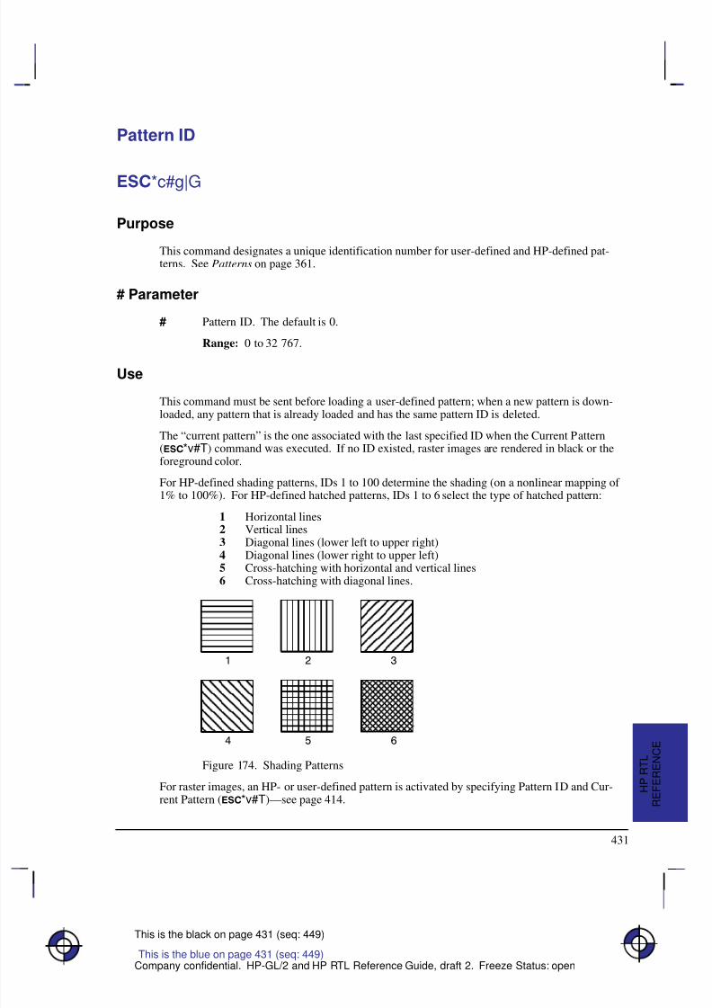
8/12/2019 HPGL2-RTL ReferenceGuide 5961-3526 540pages Sep96
http://slidepdf.com/reader/full/hpgl2-rtl-referenceguide-5961-3526-540pages-sep96 449/539
431
This is the black on page 431 (seq: 449)
Company confidential. HP-GL/2 and HP RTL Reference Guide, draft 2. Freeze Status: open
Pattern ID
*c#g|G
Purpose
This command designates a unique identification number for user-defined and HP-defined pat-terns. See Patterns on page 361.
# Parameter
# Pattern ID. The default is 0.
Range: 0 to 32 767.
Use
This command must be sent before loading a user-defined pattern; when a new pattern is down-loaded, any pattern that is already loaded and has the same pattern ID is deleted.
The “current pattern” is the one associated with the last specified ID when the Current Pattern(*v#T) command was executed. If no ID existed, raster images are rendered in black or theforeground color.
For HP-defined shading patterns, IDs 1 to 100 determine the shading (on a nonlinear mapping of 1% to 100%). For HP-defined hatched patterns, IDs 1 to 6 select the type of hatched pattern:
1 Horizontal lines
2 Vertical lines3 Diagonal lines (lower left to upper right)4 Diagonal lines (lower right to upper left)5 Cross-hatching with horizontal and vertical lines6 Cross-hatching with diagonal lines.
Ç Ç Ç Ç
Ç Ç Ç Ç
Ç Ç Ç Ç
Ç Ç Ç Ç
É É É É
É É É É
É É É É
É É É É
Figure 174. Shading Patterns
For raster images, an HP- or user-defined pattern is activated by specifying Pattern ID and Cur-rent Pattern (*v#T)—see page 414.
This is the blue on page 431 (seq: 449)
R E F E R E N C E
H P R T L
8/12/2019 HPGL2-RTL ReferenceGuide 5961-3526 540pages Sep96
http://slidepdf.com/reader/full/hpgl2-rtl-referenceguide-5961-3526-540pages-sep96 450/539
432
This is the black on page 432 (seq: 450)
Company confidential. HP-GL/2 and HP RTL Reference Guide, draft 2. Freeze Status: open
Pattern Reference Point
*p#r|R
Purpose
This command sets the “tiling” (replication) of patterns with respect to the Current Active Posi-tion (CAP) rather than position (0,0). See Patterns on page 361.
# Parameter
# Only the value 0 is allowed.
Range: 0. The command is ignored for other values.
Use
Note: A similar, though not identical HP-GL/2 instruction is AC (Anchor Corner).
This is the blue on page 432 (seq: 450)
8/12/2019 HPGL2-RTL ReferenceGuide 5961-3526 540pages Sep96
http://slidepdf.com/reader/full/hpgl2-rtl-referenceguide-5961-3526-540pages-sep96 451/539
433
This is the black on page 433 (seq: 451)
Company confidential. HP-GL/2 and HP RTL Reference Guide, draft 2. Freeze Status: open
Pattern Transparency Mode
*v#o|O
Purpose
This command sets the pattern transparency mode. See Patterns on page 361.
# Parameter
# The following values are allowed. The default is 0.
0 Transparent; the pattern’s white pixels are not applied to the destination; the destina-tion image shows through the pattern.
1 Opaque; the pattern’s white pixels are applied to the destination; the correspondingparts of the destination image are blocked out by the pattern.
Range: 0, 1. Other values cause the command to be ignored.
Use
A value of 0 makes the pattern’s white areas transparent, allowing the corresponding parts of thedestination image to show through. With a transparency mode of 1, the white pixels in the patternare applied directly to the destination.
This command is ignored during raster mode.
This is the blue on page 433 (seq: 451)
R E F E R E N C E
H P R T L
8/12/2019 HPGL2-RTL ReferenceGuide 5961-3526 540pages Sep96
http://slidepdf.com/reader/full/hpgl2-rtl-referenceguide-5961-3526-540pages-sep96 452/539
434
This is the black on page 434 (seq: 452)
Company confidential. HP-GL/2 and HP RTL Reference Guide, draft 2. Freeze Status: open
Push/Pop Palette
*p#p|P
Purpose
This command saves (pushes) or restores (pops) the palette from the palette stack.
# Parameter and Termination Character
# The following values are allowed. The default is 0.
0 Pushes (saves) the palette.
1 Pops (restores) the palette.
Range: 0 or 1. This command is ignored for other values. A value of 0 pushes the cur-rent palette, which is unaffected. A value of 1 pops the most recently pushed palette,which overwrites the current palette and becomes the new current palette. As with anystack, the last item pushed is the first item popped.
Use
Pushing a palette saves the following parameters to allow for palette restoration:
Color definitions for each palette entry.
Pen widths (the palette is also used in HP-GL/2).
Black and white references.
Number of bits per index expected for raster transfers.
Pixel encoding mode.
Number of bits per primary expected for raster transfers.
Stack size is limited by the device’s available memory. Pushes past the stack limit or attempts topop an empty stack are ignored. E empties the palette stack and overwrites the current pal-ette with the default black and white palette. Entering PJL, which causes an E, has the sameeffect. The HP-GL/2 instructions IN and BP overwrite the current palette with the default HP-GL/2 palette, but have no effect on the palette stack.
This is the blue on page 434 (seq: 452)
8/12/2019 HPGL2-RTL ReferenceGuide 5961-3526 540pages Sep96
http://slidepdf.com/reader/full/hpgl2-rtl-referenceguide-5961-3526-540pages-sep96 453/539
435
This is the black on page 435 (seq: 453)
Company confidential. HP-GL/2 and HP RTL Reference Guide, draft 2. Freeze Status: open
Raster Line Path
*b#l|L
Purpose
This command specifies the following:
The vertical direction that a Transfer Raster Data by Row/Block (*b#W) command incre-
ments the raster row within an image.
The vertical direction that the Y Offset (*b#Y) command moves the CAP.
The vertical direction in which an explicit or implicit End Raster Graphics (*rC) com-
mand moves the CAP if a Source Raster Height (
*r#T) command has been specified.The handling of line feeds in HP-GL/2 labels is not affected.
# Parameter
# The following values are allowed. The default is 0.
0 Increment raster row in the +Y direction of the HP RTL coordinate system.
1 Increment raster row in the –Y direction of the HP RTL coordinate system.
Range: 0, 1 (a missing value is interpreted as 0, and other values cause the command tobe ignored).
Use
This command is ignored after the Start Raster Graphics (*r#A) or Transfer Raster Data(*b#V or *b#W) commands until the next explicit or implicit End Raster Graphics(*rC) command. Since the raster image will “grow” in the specified direction, it is the user’sresponsibility to position the CAP to avoid unwanted overlaying of the image with vector or otherraster graphics.
This is the blue on page 435 (seq: 453)
R E F E R E N C E
H P R T L
8/12/2019 HPGL2-RTL ReferenceGuide 5961-3526 540pages Sep96
http://slidepdf.com/reader/full/hpgl2-rtl-referenceguide-5961-3526-540pages-sep96 454/539
436
This is the black on page 436 (seq: 454)
Company confidential. HP-GL/2 and HP RTL Reference Guide, draft 2. Freeze Status: open
Render Algorithm
*t#j|J
Purpose
This command selects the algorithm to be used for rendering page marking entities on a givenpage. See Halftoning on page 360.
# Parameter
# The following values are allowed. The default is 0; note that the PCL default for thiscommand is 3.
0 Device best.
3 Pattern dither (to be made obsolete; use 11 instead).
5 Device best (monochrome).
7 Cluster-ordered dither.
8 Cluster-ordered dither (monochrome).
11 Pattern dither.
12 Pattern dither (monochrome).
13 Scatter dither.
14 Scatter dither (monochrome).Range: 0, 3, 5, 7, 8, 11, 12, 13, 14. The command is ignored for other values of theparameter.
Use
The device-best halftone algorithm is device-dependent.
Monochrome Rendering: A gray value is generated from the three primary colors; this value iscomputed according to the NTSC standard, which for device RGB color space is
Gray = 0.3 Red + 0.59 Green + 0.11 Blue.
Cluster-Ordered Dither: A pixel is intensified at a point (x,y) depending on the desired intensity,
I(x,y), and on an n-by-n dither matrix, D, wherei = x modulo n j = y modulo n.
For RGB color spaces, if I(x,y) < D(i,j), the point corresponding to (x,y) is intensified; otherwiseit is not. The intensity of each primary color is determined according to this scheme. The rela-tionship between I and D depends on the specified color space.
This is the blue on page 436 (seq: 454)
8/12/2019 HPGL2-RTL ReferenceGuide 5961-3526 540pages Sep96
http://slidepdf.com/reader/full/hpgl2-rtl-referenceguide-5961-3526-540pages-sep96 455/539
437
This is the black on page 437 (seq: 455)
Company confidential. HP-GL/2 and HP RTL Reference Guide, draft 2. Freeze Status: open
Reset
E
Purpose
This command causes the following actions:
Prints any partial pages of data which may have been received. Reset does not cause a page
eject if the page does not contain an image (raster graphics or HP-GL/2 graphics).
Executes the HP-GL/2 instructions BP (Begin Plot) and IN (Initialize).
Resets all programmable features to their default values. Programmable features whose de-
faults can be set from the front panel are set to those defaults. Values reset are:Graphics resolution
Compression method
Seed row
Source width to logical page width
Bits per index
Pixel encoding mode
Number of bits of red, green, and blue
Scaling off
Render algorithm to device-best
Foreground color
Logical operation
Source and pattern transparency to transparent
Current pattern to solid
Pattern reference point to (0,0)
Palette HP RTL black-and-white.
Returns and fixes the HP RTL CAP to (0,0).
Deletes temporary patterns.
Returns the device to HP RTL parsing mode.
Implicitly ends raster mode, if necessary.
This is the blue on page 437 (seq: 455)
R E F E R E N C E
H P R T L
8/12/2019 HPGL2-RTL ReferenceGuide 5961-3526 540pages Sep96
http://slidepdf.com/reader/full/hpgl2-rtl-referenceguide-5961-3526-540pages-sep96 456/539
438
This is the black on page 438 (seq: 456)
Company confidential. HP-GL/2 and HP RTL Reference Guide, draft 2. Freeze Status: open
# Parameter and Termination Character
There is no value parameter.
This command cannot be combined with others that follow. The uppercase “E” terminator mustbe used with this command.
Use
The uppercase “E” terminator must be used with this command. There is no value parameter.
Both the HP-GL/2 and HP RTL contexts recognize the Reset command.
After the Reset command, the device remains online, no subsequent data is lost, and there is noeffect on I/O or host-to-peripheral communication.
E is a valid HP-GL/2 terminator, and incorporates all the functionality of the BP (Begin Plot)and IN (Initialize) instructions, as well as defaulting the HP RTL and HP-GL/2 palettes.
Within an HP-GL/2 label, when transparent data mode is on (“TD1;”), E is interpreted as dataand does not reset the device. When “TD0;” is in effect, the command causes a reset.
When the device is expecting HP RTL data, E is interpreted as data and does not reset thedevice. The device expects HP RTL data following the HP RTL commands Configure ImageData (*v#W), Transfer Raster Data by Plane (*b#V), and Transfer Raster Data by Row/ Block (*b#W). The length of the data the device expects varies and is specified in eachcommand.
This is the blue on page 438 (seq: 456)
8/12/2019 HPGL2-RTL ReferenceGuide 5961-3526 540pages Sep96
http://slidepdf.com/reader/full/hpgl2-rtl-referenceguide-5961-3526-540pages-sep96 457/539
439
This is the black on page 439 (seq: 457)
Company confidential. HP-GL/2 and HP RTL Reference Guide, draft 2. Freeze Status: open
Set Blue Parameter
*v#c|C
Purpose
This command specifies the blue component of any new color entry of the color palette.
# Parameter
# Blue parameter. The default is 0.
Range: Black reference to white reference for blue (as defined in the Configure ImageData command, *v#W). Out-of-range values are clamped. (The absolute limits are
–32 768 to 32 767.)
Use
The parameter is applied and then initialized to 0 after each Assign Color Index command(*v#I).
This is the blue on page 439 (seq: 457)
R E F E R E N C E
H P R T L
8/12/2019 HPGL2-RTL ReferenceGuide 5961-3526 540pages Sep96
http://slidepdf.com/reader/full/hpgl2-rtl-referenceguide-5961-3526-540pages-sep96 458/539
440
This is the black on page 440 (seq: 458)
Company confidential. HP-GL/2 and HP RTL Reference Guide, draft 2. Freeze Status: open
Set Graphics Resolution
*t#r|R
Purpose
This command defines the resolution at which graphics data is to be plotted or printed.
# Parameter
# Resolution in dots per inch (dpi). The default resolution is device-dependent.
Range: 0 through 32 767 (out-of-range values are clamped). The 0 through 32 767range represents HP RTL limits; device limits may be more restrictive. The actual phys-
ical (or native) resolution is device-dependent. Support of continuous or incrementalresolution is device-dependent.
Use
If the requested resolution is not supported, the resolution value is mapped to the next higher sup-ported resolution to ensure that the picture is printed without data loss. For example, if a devicesupports both 180 dpi and 90 dpi and the requested resolution is greater than 90 dpi, 180 dpi isselected; otherwise 90 dpi is selected. If the resolution value is greater than the maximum for thedevice, that maximum is used.
The graphics resolution is ignored in raster scaling mode. The supplied source and destinationwidths and heights are used instead; see page 347.
This command is ignored during raster mode.
On devices that support several native resolutions, the image is first scaled up or down to the na-tive resolution selected by the @PJL SET RESOLUTION command. Selecting a low nativeresolution uses less memory but has more granularity; it is more appropriate for draft quality. Ahigh native resolution uses more memory but has better quality. For example, if the resolution isset to 300 dpi through PJL and the Set Graphics Resolution command specifies a larger value(such as 600), the image is scaled down to 300 dpi, with loss of detail. If the device’s machineresolution is 600 dpi, pixels are then replicated.
See also Controlling Image Resolution on page 344.
This is the blue on page 440 (seq: 458)

8/12/2019 HPGL2-RTL ReferenceGuide 5961-3526 540pages Sep96
http://slidepdf.com/reader/full/hpgl2-rtl-referenceguide-5961-3526-540pages-sep96 459/539
441
This is the black on page 441 (seq: 459)
Company confidential. HP-GL/2 and HP RTL Reference Guide, draft 2. Freeze Status: open
Set Green Parameter
*v#b|B
Purpose
This command specifies the green component of any new color entry of the color palette.
# Parameter
# Green parameter. The default is 0.
Range: Black reference to white reference for green (as defined in the Configure ImageData command, *v#W). Out-of-range values are clamped. (The absolute limits are
–32 768 to 32 767.)
Use
The parameter is applied and then initialized to 0 after each Assign Color Index command(*v#I).
This is the blue on page 441 (seq: 459)
R E F E R E N C E
H P R T L
8/12/2019 HPGL2-RTL ReferenceGuide 5961-3526 540pages Sep96
http://slidepdf.com/reader/full/hpgl2-rtl-referenceguide-5961-3526-540pages-sep96 460/539
442
This is the black on page 442 (seq: 460)
Company confidential. HP-GL/2 and HP RTL Reference Guide, draft 2. Freeze Status: open
Set Red Parameter
*v#a|A
Purpose
This command specifies the red component of any new color entry of the color palette.
# Parameter
# Red parameter. The default is 0.
Range: Black reference to white reference for red (as defined in the Configure ImageData command, *v#W). Out-of-range values are clamped. (The absolute limits are
–32 768 to 32 767.)
Use
The parameter is applied and then initialized to 0 after each Assign Color Index command(*v#I).
This is the blue on page 442 (seq: 460)
8/12/2019 HPGL2-RTL ReferenceGuide 5961-3526 540pages Sep96
http://slidepdf.com/reader/full/hpgl2-rtl-referenceguide-5961-3526-540pages-sep96 461/539
443
This is the black on page 443 (seq: 461)
Company confidential. HP-GL/2 and HP RTL Reference Guide, draft 2. Freeze Status: open
Simple Color
*r#u|U
Purpose
This command creates a fixed-size palette whose color specification cannot be modified. Thepixel encoding mode is always indexed planar.
# Parameter and Termination Character
# The following values are allowed. The default is to use the current palette, which maybe the HP-GL/2 palette.
–4 Four planes, device black/cyan/magenta/yellow (KCMY) palette.
–3 Three planes, device cyan/magenta/yellow (CMY) palette.
1 One plane, black.
3 Three planes, device red/green/blue (RGB) palette.
Range: –4, –3, 1, 3.
Use
This command creates a new palette and overwrites the current palette. HP RTL commands andHP-GL/2 instructions that modify the palette (NP, PC, *v#A, *v#B, *v#C, and
*v#I) are ignored. When a Simple Color palette is popped from the stack (using
*p#P), itcannot be modified; pixel encoding then reverts to indexed planar.
RGB, CMY, or KCMY raster data must be sent by plane (using *b#V) as well as by row(with *b#W). The last plane in each row is sent using the *b#W command; all otherplanes are sent using the *b#V command.
When KCMY mode is selected:
– HP RTL devices lock out the Color Model and HP-GL/2 objects, so KCMY raster objectscannot be mixed with any other object on the same page.
– Raster scaling is also ignored in this mode.
– Gray-scaling in KCMY mode is rendered as black and white, but the gray-scale algorithm isdevice-dependent.
– Transparencies and logical operations are not supported.
When CMY mode is selected using the Simple Color command, it is device-dependent whetheryou can use scaling.
Planes must be sent in order; for example, for CMY, cyan, magenta, yellow.
The Simple Color palettes are listed on the next page.
This is the blue on page 443 (seq: 461)
R E F E R E N C E
H P R T L
8/12/2019 HPGL2-RTL ReferenceGuide 5961-3526 540pages Sep96
http://slidepdf.com/reader/full/hpgl2-rtl-referenceguide-5961-3526-540pages-sep96 462/539
444
This is the black on page 444 (seq: 462)
Company confidential. HP-GL/2 and HP RTL Reference Guide, draft 2. Freeze Status: open
4-plane KCMY (value = –4)
Index Black Color
pen pen(s) 0 White White 1 Black White 2 White Cyan 3 Black Cyan 4 White Magenta 5 Black Magenta 6 White Blue 7 Black Blue 8 White Yellow 9 Black Yellow 10 White Green 11 Black Green 12 White Red
13 Black Red 14 White Black 15 Black Black
3-plane CMY (value = –3)
Index Color 0 White 1 Cyan 2 Magenta 3 Blue 4 Yellow 5 Green
6 Red 7 Black
Single-plane K (value = 1)
Index Color 0 White 1 Black
3-plane RGB (value = 3)
Index Color 0 Black
1 Red 2 Green 3 Yellow 4 Blue 5 Magenta 6 Cyan 7 White
This is the blue on page 444 (seq: 462)
8/12/2019 HPGL2-RTL ReferenceGuide 5961-3526 540pages Sep96
http://slidepdf.com/reader/full/hpgl2-rtl-referenceguide-5961-3526-540pages-sep96 463/539
445
This is the black on page 445 (seq: 463)
Company confidential. HP-GL/2 and HP RTL Reference Guide, draft 2. Freeze Status: open
Source Raster Height
*r#t|T
Purpose
This command specifies the height in pixel rows of the source raster image denoted by subse-quent Start Raster Graphics (*r#A) commands. Height is perpendicular to the pixel rows andis measured in the direction specified by the Raster Line Path command (*r#L).
# Parameter
# Height in pixel rows. There is no default.
Range: 0 through 65 535 (out-of-range values are clamped). A missing parameter isinterpreted as 0.
Note: The 65 535 limit is the HP RTL limit. Actual limits are device-dependent. Values exceed-ing the device limits are clamped.
Use
The Source Raster Width (*r#S) and Source Raster Height commands must precede a StartRaster Graphics (*r#A) command where scale mode is set to “on” (parameter value 2 or 3).Without the Source Raster Width and Source Raster Height commands, raster graphics will beginwith the scale mode off, that is, as if a parameter value of 0 or 1 were sent.
A Reset command causes an explicitly set source raster height to become undefined.
Plane or row data that is not specified for the full source raster height is filled out with zeros.Zero-filled data is printed in the color specified for index 0 in the palette.
When a Transfer Raster Data (*b#V or *b#W) command is received that causes any pixelrow to extend beyond the row boundary set by the Source Raster Height command, the row out-side the boundary is clipped. This includes the case where the CAP is moved beyond the heightboundary or above the starting position with a Y Offset (*b#Y) command and the printing of raster data is attempted.
If the user has specified a source raster height of 0 and a Start Raster Graphics (or Transfer RasterData) command is received, then the entire raster graphic is clipped.
If the user has not set the source raster height, then raster height is not used; that is, there is nodefault value.
Upon receiving an explicit or implicit End Raster Graphics command, the CAP is set to the leftgraphics margin of the next pixel row after the raster height boundary. The location of the “next”pixel row depends on the direction specified by the Raster Line Path command.
See also Setting the Width and Height in HP RTL on page 342.
This is the blue on page 445 (seq: 463)
R E F E R E N C E
H P R T L
8/12/2019 HPGL2-RTL ReferenceGuide 5961-3526 540pages Sep96
http://slidepdf.com/reader/full/hpgl2-rtl-referenceguide-5961-3526-540pages-sep96 464/539
446
This is the black on page 446 (seq: 464)
Company confidential. HP-GL/2 and HP RTL Reference Guide, draft 2. Freeze Status: open
Source Raster Width
*r#s|S
Purpose
This command specifies the width in pixels of the source raster image denoted by subsequentStart Raster Graphics (*r#A) commands. Width is in the direction of (parallel to) the rasterrows.
# Parameter
# Width in pixels. The default is the logical page width for unscaled graphics (from the
left graphics margin), undefined for scaled graphics.Range: 0 through 65 535 (out-of-range values are clamped). A missing parameter isassumed to be 0.
Note: The 65 535 limit is the HP RTL limit. Actual limits are device-dependent. Values exceed-ing the device limits are clamped.
Use
The Source Raster Width and Source Raster Height (*r#T) commands must precede a StartRaster Graphics (*r#A) command where scale mode is set to “on” (parameter value 2 or 3).Without the Source Raster Width and Source Raster Height commands, raster graphics will beginwith the scale mode off, that is, as if a parameter value of 0 or 1 were sent.
The default source raster width is also affected by changes in the left graphics margin; that is, if aStart Raster Graphics command is sent with a parameter value of 1 or 3 (which sets the leftgraphics margin to the CAP), the default source raster width is interpreted as extending from theleft graphics margin to the right edge of the logical page. This “tracking” behavior terminateswhen the source raster width is set explicitly, and resumes after a Reset (E) command.
Plane or row data that is not specified for the full source raster width is filled out with zeros; dataexceeding the source raster width is clipped. (Zero-filled data is printed in the color specified forindex 0 in the palette.)
If the user specified a source raster width of 0 and a Start Raster Graphics (or Transfer RasterData) command is received, the entire raster graphic is clipped.
This command is ignored during raster mode.
See also Setting the Width and Height in HP RTL on page 342.
This is the blue on page 446 (seq: 464)
8/12/2019 HPGL2-RTL ReferenceGuide 5961-3526 540pages Sep96
http://slidepdf.com/reader/full/hpgl2-rtl-referenceguide-5961-3526-540pages-sep96 465/539
447
This is the black on page 447 (seq: 465)
Company confidential. HP-GL/2 and HP RTL Reference Guide, draft 2. Freeze Status: open
Source Transparency Mode
*v#n|N
Purpose
This command sets the source image’s transparency mode to transparent or opaque.
# Parameter
# The following values are allowed. The default is 0.
0 Transparent; the source’s white pixels are not applied to the destination; the destina-tion image shows through the source.
1 Opaque; the source’s white pixels are applied to the destination; the correspondingparts of the destination image are blocked out by the source.
Range: 0, 1. Other values cause the command to be ignored.
Use
A value of 0 makes the source’s white areas transparent, allowing the corresponding parts of thedestination image to show through. With a transparency mode of 1, the white pixels in the sourceare applied directly to the destination.
This command is ignored during raster mode.
Note: Some devices do not support this command; consider using the HP-GL/2 TR (Transpar-ency Mode) instruction instead.
This is the blue on page 447 (seq: 465)
R E F E R E N C E
H P R T L
8/12/2019 HPGL2-RTL ReferenceGuide 5961-3526 540pages Sep96
http://slidepdf.com/reader/full/hpgl2-rtl-referenceguide-5961-3526-540pages-sep96 466/539
448
This is the black on page 448 (seq: 466)
Company confidential. HP-GL/2 and HP RTL Reference Guide, draft 2. Freeze Status: open
Start Raster Graphics
*r#a|A
Purpose
This command places the device in raster mode with scale mode on or off, fixes the starting posi-tion of the graphics image, and sets the left graphics margin.
# Parameter
# The following values are allowed. The default value is 0.
0 Start raster graphics at logical page left bound.
1 Start raster graphics at the current active position (CAP).
2 Turn on scale mode and start graphics at logical page left boundary.
3 Turn on scale mode and start graphics at the CAP.
Range: 0 through 3 (out-of-range values default to 0).
Use
Both Source Raster Width (*r#S) and the Source Raster Height (*r#T) must be specifiedbefore starting raster graphics in scale mode. If neither is specified, or if only one is specified, aStart Raster Graphics command with a parameter value of 2 or 3 will function as if the parameter
value were 0 or 1, respectively; that is, raster graphics will start with scale mode off.A value of 0 or 2 starts the image at the current vertical position on the left boundary of the log-ical page; that is, the left graphics margin is set to 0. A value of 1 or 3 starts the image at thecurrent position; that is, the left graphics margin is set to the current horizontal position.
For a Raster Line Path (*b#L) of 0 (the default), the starting corner becomes the upper leftcorner of the image. For a Raster Line Path of 1, the starting corner becomes the lower left cor-ner of the picture.
Values of 2 or 3 turn scale mode on. Scaled images are rendered in the specified size independentof device resolution.
On devices that support several native resolutions, the image is first scaled up or down to the na-tive resolution selected by the @PJL SET RESOLUTION command. Selecting a low native
resolution uses less memory but has more granularity; it is more appropriate for draft quality. Ahigh native resolution uses more memory but has better quality.
Note: When you scale an image down, loss of detail always results. The algorithm used for scal-ing down is device-dependent
See also Implicit Start Raster Graphics on page 376.
This is the blue on page 448 (seq: 466)
8/12/2019 HPGL2-RTL ReferenceGuide 5961-3526 540pages Sep96
http://slidepdf.com/reader/full/hpgl2-rtl-referenceguide-5961-3526-540pages-sep96 467/539
449
This is the black on page 449 (seq: 467)
Company confidential. HP-GL/2 and HP RTL Reference Guide, draft 2. Freeze Status: open
Transfer Raster Data by Plane
*b#V[data]
Purpose
This command transfers the number of bytes specified in the value field to the device, but doesnot move the CAP to the next raster row. The plane pointer is incremented, but not the row point-er.
# Parameter and Termination Character
# Number of bytes in the data field. If data is compressed, this refers to the length of the
compressed data. There is no default.Range: 0 through 32 767. Out-of-range values are clamped.
If the number of bytes specified in the value field (#) is greater than 32 767, the first 32 767 bytesfollowing the command are interpreted as data, and byte 32 768 is interpreted as the beginning of the next HP RTL command.
This command cannot be combined with others that follow. The uppercase “V” terminator mustbe used with this command.
Use
Use this command to send each plane except the last in a multi-plane raster row. It is not used forsingle-plane rows, or for the last plane in a multi-plane row, since row position is not affected bythis command. To transfer raster data and increment the row pointer, the Transfer Raster Data byRow/Block (*b#W) command must be sent. The least significant planes are sent first (see
Multi-Plane Data on page 358).
The number of data bytes is independent of source raster width and can vary from plane to plane.If the image width can accommodate more data than is sent, the undefined data is assumed to beall zeros. For information on how to use this feature, see Setting the Width and Height in HP RTLon page 342.
Empty planes can be sent using Transfer Raster Data by Plane with a value of 0 (*b0V).A row can be ended “early” with a Transfer Raster Data by Row/Block with a value of 0(*b0W). Absent data is assumed to be zeros: in row-by-row raster mode, when the com-bined planes yield an index of 0, those pixels are rendered with whatever color has been assignedto index number 0 in the color palette. (This command is not used in plane-by-plane raster
mode.) This can be used as a method of data compression.
Extra planes are ignored. For example, if three planes have been assigned to each row with theSet Number of Bits per Index byte of the Configure Image Data (*v#W) command, but fourplanes are sent for a given row, the fourth plane is ignored. If a Transfer Raster Data by Row/ Block command is used for one of the extra color planes, the data is ignored, but the row isincremented and subsequent planes are again interpreted as valid data (for the next row).
The data in the data field is interpreted according to the current compression method. This com-mand is used only for row-based compression methods. The Transfer Raster Data by Plane
This is the blue on page 449 (seq: 467)
R E F E R E N C E
H P R T L

8/12/2019 HPGL2-RTL ReferenceGuide 5961-3526 540pages Sep96
http://slidepdf.com/reader/full/hpgl2-rtl-referenceguide-5961-3526-540pages-sep96 468/539
450
This is the black on page 450 (seq: 468)
Company confidential. HP-GL/2 and HP RTL Reference Guide, draft 2. Freeze Status: open
command and its associated data are parsed and ignored if sent when a block-based compressionmethod is in effect. See the Compression Method (*b#M) command for a listing of row-based and block-based compression methods.
This command is only allowed in row-by-row raster mode. (Plane-by-plane raster mode requiresonly one plane of data at a time, so this command is not needed.) If this command is receivedwhen the device is in plane-by-plane raster mode, the command and its associated data are parsedand ignored.
Note: When an explicit or implicit End Raster Graphics (*rC) command is received beforethe row is completed with a Transfer Data by Row/Block command, it is device-dependentwhether or not the incomplete row is rendered. See the note under the End Raster Graphicscommand.
Note: If a block of data is transferred using a block-based compression mode before the previousrow is completely defined, the plane pointer is set to the first plane of the next row at the begin-ning of the block transfer. As with End Raster Graphics, it is device-dependent whether or notthe incomplete row is rendered.
This is the blue on page 450 (seq: 468)
8/12/2019 HPGL2-RTL ReferenceGuide 5961-3526 540pages Sep96
http://slidepdf.com/reader/full/hpgl2-rtl-referenceguide-5961-3526-540pages-sep96 469/539
451
This is the black on page 451 (seq: 469)
Company confidential. HP-GL/2 and HP RTL Reference Guide, draft 2. Freeze Status: open
Transfer Raster Data by Row/Block
*b#W[data]
Purpose
This command transfers the number of bytes specified in the value field to the device in arow-by-row or block format depending on the current compression method (*b#M).
# Parameter and Termination Character
# Number of bytes in the data field. If data is compressed, this refers to the length of thecompressed data. There is no default.
Range: 0 through 2 147 483 647 (231 – 1) (out-of-range values are clamped).
This command cannot be combined with others that follow. The uppercase “W” terminator mustbe used with this command.
Use
For row-based formats, this command is used for single-plane rows (including those sent inplane-by-plane mode) or for the last plane in a multi-plane row. After execution, the row pointeris incremented, the plane pointer in a multi-plane row is reset to 1, and the CAP is set to the leftgraphics margin at the start of the next row.
For block-based formats, this command is used for block transfer of single- or multi-plane rowswith implied or explicit row and plane divisions. Row and plane divisions depend on the numberof planes and the current compression method. At the end of the block transfer, the row pointer isincremented, the plane pointer is set to the first plane of the next row, and the CAP is set to theleft graphics margin.
Empty or incomplete rows may be sent. See Transfer Raster Data by Plane (*b#V).
This is the blue on page 451 (seq: 469)
R E F E R E N C E
H P R T L
8/12/2019 HPGL2-RTL ReferenceGuide 5961-3526 540pages Sep96
http://slidepdf.com/reader/full/hpgl2-rtl-referenceguide-5961-3526-540pages-sep96 470/539
452
This is the black on page 452 (seq: 470)
Company confidential. HP-GL/2 and HP RTL Reference Guide, draft 2. Freeze Status: open
Universal Exit Language/Start of PJL
%–12345X
Purpose
This command causes the current context processor to shut down in an orderly fashion and exitinto the Printer Job Language (PJL). See page 394 for more information about PJL.
# Parameter and Termination Character
# –12345 Exit the current language context and start PJL.
Range: –12345. Only the exact nine-character sequence (%–12345X) is guaran-
teed to cause exit from the current language context. Note that the value (–12345) is astring of characters and not an integer value.
This command cannot be combined with others that follow. The uppercase “X” terminator mustbe used with this command.
Use
This command performs the following actions:
Performs all the actions associated with the Reset command (E).
Turns control over to PJL.
The command is always recognized in both the HP-GL/2 and HP RTL contexts, except in the fol-lowing cases:
In the HP-GL/2 context, within an HP-GL/2 label, when transparent data mode is on
(“TD1”).
In the HP RTL context, when in an HP RTL binary data transfer.
Note: Devices that support only HP-GL/2 and HP RTL may ignore this command. On devicesthat support additional language contexts, the command may or may not be recognized in thosecontexts.
This is the blue on page 452 (seq: 470)
8/12/2019 HPGL2-RTL ReferenceGuide 5961-3526 540pages Sep96
http://slidepdf.com/reader/full/hpgl2-rtl-referenceguide-5961-3526-540pages-sep96 471/539
453
This is the black on page 453 (seq: 471)
Company confidential. HP-GL/2 and HP RTL Reference Guide, draft 2. Freeze Status: open
Y Offset
*b#y|Y
Purpose
This command moves the CAP vertically the number of pixel rows specified in the value field.
# Parameter
# Number of pixel rows of vertical movement. There is no default.
Range: –32 767 through 32 767 (out-of-range values are clamped; a missing value isinterpreted as 0).
Use
Use a plus sign (+) before the value, or an unsigned value, to move the CAP in the direction spe-cified by the Raster Line Path (*b#L) command. Use a minus sign (–) before the value tomove the CAP in the direction opposite to the raster line path. The CAP is allowed to move out-side the logical page. Unlike the Move CAP commands (*p#X, *p#Y, and &a#H),there is no absolute move possible with this command.
This command is to be made obsolete outside of raster mode.
When Y Offset is used in raster mode, skipped rows are zero-filled up to the offset requested, orthe current source raster height, whichever comes first. If a negative Y Offset value places theCAP above the position at which raster graphics was started (or below in the case of Raster LinePath = 1), no zero-filling is done for rows that lie outside the raster area.
The physical distance that this command moves the CAP varies according to the current resolu-tion.
Executing this command causes the seed row to be zeroed, even if the command has a 0 or miss-ing parameter value (#).
This command is ignored during raster scaling mode. Use the Move CAP Vertical (*p#Y)command instead.
Note: When this command is received before a row is completed, it is device-dependent whetheror not the incomplete row is rendered. If it is rendered, the incomplete row is zero filled, the rowpointer is incremented, and the plane pointer is reset to 1. If it is not rendered, the row pointer isnot incremented as a result of the incomplete row.
This is the blue on page 453 (seq: 471)
R E F E R E N C E
H P R T L

8/12/2019 HPGL2-RTL ReferenceGuide 5961-3526 540pages Sep96
http://slidepdf.com/reader/full/hpgl2-rtl-referenceguide-5961-3526-540pages-sep96 472/539
454
This is the black on page 454 (seq: 472)
Company confidential. HP-GL/2 and HP RTL Reference Guide, draft 2. Freeze Status: open
8/12/2019 HPGL2-RTL ReferenceGuide 5961-3526 540pages Sep96
http://slidepdf.com/reader/full/hpgl2-rtl-referenceguide-5961-3526-540pages-sep96 473/539
455
This is the black on page 455 (seq: 473)
Company confidential. HP-GL/2 and HP RTL Reference Guide, draft 2. Freeze Status: open
Chapter 15: Summary of HP RTLDevice-Dependencies
The following table lists the HP RTL characteristics that can vary among devices.
Dependency Description
Resolution, Rendering, and Scaling
Size and spacing of dots See Raster Graphics on page 344.
Native device resolution The actual number of dots per inch (dpi) a device can plot.“Native” resolutions are usually a multiple of physical deviceresolution. Native resolutions can be set by the @PJL SETRESOLUTION command. See Controlling Image Resolutionon page 344, the Set Graphics Resolution (*t#R) commandon page 440, the Move CAP (*p#X and *p#Y) com-mands on pages 426 and 427, and Printer Job Language (PJL)on page 394.
Resolution type Options are continuous or incremental resolution. Only devicesthat support continuous resolution can accurately plot a specific
resolution. See Continuous and Incremental Resolution on page345 and the Set Graphics Resolution (*t#R) command onpage 440.
Resolution Range andDefault
Allowable range and default for the Set Graphics Resolution(*t#R) command. The resolution setting is independent of the physical device resolution. Images are scaled to the re-quested resolution. If explicit scaling is requested in the StartRaster Graphics (*r#A) command, the resolution setting isignored. See Controlling Image Resolution on page 344, Draft and Final Resolution on page 345, and the Set Graphics Resolu-tion command on page 440.
Scaled-Down Rendering When scaling an image down, loss of detail always results. Thealgorithm used for scaling down is device-dependent. See Con-trolling Image Resolution on page 344 and Scaling Raster
Images on page 345.
This is the blue on page 455 (seq: 473)
D E V I C E S
H P R T
L
8/12/2019 HPGL2-RTL ReferenceGuide 5961-3526 540pages Sep96
http://slidepdf.com/reader/full/hpgl2-rtl-referenceguide-5961-3526-540pages-sep96 474/539
456
This is the black on page 456 (seq: 474)
Company confidential. HP-GL/2 and HP RTL Reference Guide, draft 2. Freeze Status: open
Dependency Description
Resolution, Rendering, and Scaling (continued)
Source Raster Height(*r#T) and SourceRaster Width (*r#S)Ranges
These ranges are determined by a device’s physical limits. SeeSetting the Width and Height in RTL on page 342, and the com-mand descriptions on pages 446 and 445.
Plot Management
Large Plots What happens if a plot is too large to fit into the memory of thedevice is device-dependent. See When Overflow Occurs onpage 377.
Negative Motion
Command Implementation
Some devices cannot simultaneously receive and plot raster
images. On these devices, the Negative Motion (&a#N)command has no effect. When the command promises no nega-tive motion and the image nonetheless contains negative mo-tion, the effect is device-dependent. See Negative Motion onpage 349 and the description of the Negative Motion commandon page 428.
Color Palette Management
Color Support Options are full color, grayscale monochrome (color maps togray), and two-tone monochrome (no color support). Two-tonemonochrome devices may not support certain HP RTL com-mands. See Primary Colors on page 354, Specifying Colors on
page 353. The actual color printed is also device-dependent.
Maximum Palette Size The larger the palette, the more colors can be explicitly defined.Palette size is set using the Number of Bits per Index byte of theConfigure Image Data (*v#W) command. The maximumvalue corresponds to the number of data planes the device sup-ports. See Defining the RTL Palette on page 356 and the Con-figure Image Data command on page 409.
Number of Bits perPrimary
This byte of the Configure Image Data (*v#W) commanddetermines the ranges for defining custom palette colors. Seepage 409.
Palette Transferability Some devices allow you to transfer the color palette betweenRTL and HP-GL/2. See Defining the RTL Palette on page 356,Transferring Pen Position and Palettes on page 393, and thedescriptions of the Enter HP-GL/2 Mode (%#B) commandon page 420 and the Enter RTL Mode (%#A) command onpage 422.
8/12/2019 HPGL2-RTL ReferenceGuide 5961-3526 540pages Sep96
http://slidepdf.com/reader/full/hpgl2-rtl-referenceguide-5961-3526-540pages-sep96 475/539
457
This is the black on page 457 (seq: 475)
Company confidential. HP-GL/2 and HP RTL Reference Guide, draft 2. Freeze Status: open
Dependency Description
Color Palette Management (continued)
Pixel Encoding Mode Some devices support a special pixel encoding mode called pla-ne-by-plane raster. Pixel encoding mode is set in the ConfigureImage Data (*v#W) command. Future devices may supportother pixel encoding modes. See the description of the Confi-gure Image Data command on page 409. Merging vector andraster data is also device-dependent; see page 394.
Non-primary Colors Some devices plot non-primary colors using a dithering tech-nique. See Defining the RTL Palette on page 356, Halftoningon page 360, and the interaction with patterns in the descriptionof the Download Pattern (*c#W) command on page 417.
Miscellaneous Dependencies
Rendering of IncompleteRows
When the CAP is moved with a Y Offset (*b#Y) command,or when raster graphics mode ends, some devices plot rows thatare incomplete; other devices discard data received so far forthat row. See the descriptions of the Y Offset command on page453, the End Raster Graphics (*rC) command on page 419,the Transfer Raster Data by Plane (*b#V) command on page449, and the Transfer Raster Data by Row/Block (*b#W)command on page 451.
Language Contexts The language context at power-on is device-dependent.
Some devices require the Enter RTL Mode (%#A)command to be issued in the HP-GL/2 context. See Changing
Language Contexts and Modes on page 393.
Some devices support language contexts other than HP-GL/2and HP RTL using the Universal Exit Language / Start of PJL(%–12345X) command. This command may or may not berecognized from within the additional contexts. See Changing
Language Contexts and Modes on page 393, Printer Job Lan-guage (PJL) on page 394,and the command description on page452.
Control Panel Settings from the control (front) panel of the device may affectplots. See Interactions with Physical Device Settings on page
391.
This is the blue on page 457 (seq: 475)
D E V I C E S
H P R T
L

8/12/2019 HPGL2-RTL ReferenceGuide 5961-3526 540pages Sep96
http://slidepdf.com/reader/full/hpgl2-rtl-referenceguide-5961-3526-540pages-sep96 476/539
458
This is the black on page 458 (seq: 476)
Company confidential. HP-GL/2 and HP RTL Reference Guide, draft 2. Freeze Status: open
8/12/2019 HPGL2-RTL ReferenceGuide 5961-3526 540pages Sep96
http://slidepdf.com/reader/full/hpgl2-rtl-referenceguide-5961-3526-540pages-sep96 477/539
459
This is the black on page 459 (seq: 477)
Company confidential. HP-GL/2 and HP RTL Reference Guide, draft 2. Freeze Status: open
PART 4: Appendixes
This Part contains the following sections:
This is the blue on page 459 (seq: 477)
8/12/2019 HPGL2-RTL ReferenceGuide 5961-3526 540pages Sep96
http://slidepdf.com/reader/full/hpgl2-rtl-referenceguide-5961-3526-540pages-sep96 478/539
460
This is the black on page 460 (seq: 478)
Company confidential. HP-GL/2 and HP RTL Reference Guide, draft 2. Freeze Status: open
8/12/2019 HPGL2-RTL ReferenceGuide 5961-3526 540pages Sep96
http://slidepdf.com/reader/full/hpgl2-rtl-referenceguide-5961-3526-540pages-sep96 479/539
461
This is the black on page 461 (seq: 479)
Company confidential. HP-GL/2 and HP RTL Reference Guide, draft 2. Freeze Status: open
Appendix A: Writing EfficientPrograms–Some Tips
Before you can write graphics programs for your plotter or printer, you must be familiar withyour computer and a programming language the computer understands. You can use any com-puter system and programming language that outputs ASCII literal strings and uses input andoutput statements to transfer information to and from a peripheral device. This book assumesthat you already have experience in the programming language you select.
This appendix discusses the following fundamental programming concepts:
Using a programming language.
How to structure a complete graphics program.
Using HP-GL/2 instructions and HP RTL commands.
Making efficient use of your system.
Page layout and positioning.
Preparing your data.
Using color.
User operations.
If you are an inexperienced HP-GL/2 or HP RTL programmer, use the following guidelines toensure success:
Know your equipment; this includes the computer and the device. Know how to write,
edit, save, and run a program. Determine how your computer sends (outputs) informationto and reads (inputs) information from peripheral devices.
Know your programming language. Get a good programming manual for the language you
are using, that is specific to your computer system. Always use the syntax your languagerequires. Common mistakes are substituting the letter O for the number zero, or a lower-case letter L for the number one. Also, substituting a semicolon for a comma or omitting a
quotation mark can make the difference between failure and success. Enter HP-GL/2 instructions as they appear in the text. You may omit spaces and, for most
instructions, the terminating semicolon.
Enter HP RTL commands exactly as they appear in the text. Normally every letter, sym-
bol, and number is significant. In some cases extra spaces have been inserted in theexamples to improve their clarity; these can safely be omitted from your programs. In allcases, the “#” character in the command definition must be replaced by a numeric value asdefined for the command.
This is the blue on page 461 (seq: 479)
T I P S
P R O G R A M M I N G

8/12/2019 HPGL2-RTL ReferenceGuide 5961-3526 540pages Sep96
http://slidepdf.com/reader/full/hpgl2-rtl-referenceguide-5961-3526-540pages-sep96 480/539
462
This is the black on page 462 (seq: 480)
Company confidential. HP-GL/2 and HP RTL Reference Guide, draft 2. Freeze Status: open
Using a Programming Language
How you send an instruction or command to your device depends on the programming lan-guage you are using. Some languages include some graphics statements, but these areprimarily for the computer’s monitor. Some common languages used for printing and plottingare BASIC, FORTRAN, Pascal, and C.
BASIC (Beginner’s All-purpose Symbolic Instruction Code) is one of the most common lan-guages used for printing and plotting. It uses statements resembling English to performmany complex operations. Note that any graphics statements included in your version of BASIC are probably designed for your computer monitor, not your printer or plotter.
FORTRAN (FORmula TRANslator) is a problem-oriented language. Programmers can think in terms of the problem and write programs as algebraic expressions and arithmetic state-ments.
Pascal is a block-structured language requiring structured programming, but still allowing
many operator and control statements.
C is a general-purpose programming language at a fairly low level, with economy of expres-sion and modern control flow and data structures as its primary attributes.
Follow these steps to send an instruction in your language:
1. Use whatever opening statements are required to define the computer’s output port andestablish the device as the recipient of an output string. These are called configurationstatements and usually must be the first statements in your program.
2. Send the string to the device using an output statement.
Note: Before sending any instructions or commands to your device, you must be certain thatyour computer and device are communicating properly. Refer to your peripheral’s documenta-tion for interconnection instructions.
Using HP-GL/2 With Programming Languages
The HP-GL/2 examples included in this book are given in a “generic” format (they show theinstructions required to perform a specific function but do not use a specific programming lan-guage). In most cases, the instructions are accompanied by a brief description of the instructionbeing used.
To see how HP-GL/2 instructions are used in BASIC and the C programming language, see thefollowing examples.
This is the blue on page 462 (seq: 480)This is the blue on page 462 (seq: 480)
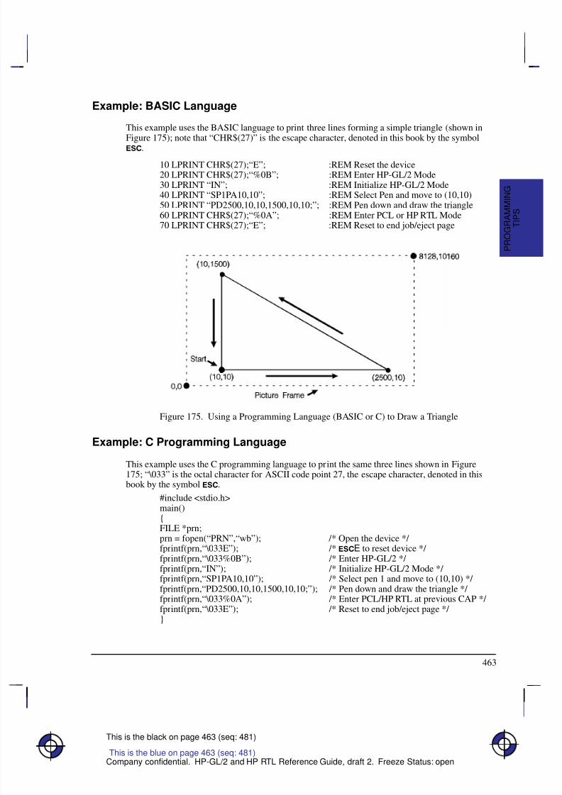
8/12/2019 HPGL2-RTL ReferenceGuide 5961-3526 540pages Sep96
http://slidepdf.com/reader/full/hpgl2-rtl-referenceguide-5961-3526-540pages-sep96 481/539
463
This is the black on page 463 (seq: 481)
Company confidential. HP-GL/2 and HP RTL Reference Guide, draft 2. Freeze Status: open
Example: BASIC Language
This example uses the BASIC language to print three lines forming a simple triangle (shown in
Figure 175); note that “CHR$(27)” is the escape character, denoted in this book by the symbol.
10 LPRINT CHR$(27);“E”; :REM Reset the device20 LPRINT CHR$(27);“%0B”; :REM Enter HP-GL/2 Mode30 LPRINT “IN”; :REM Initialize HP-GL/2 Mode40 LPRINT “SP1PA10,10”; :REM Select Pen and move to (10,10)50 LPRINT “PD2500,10,10,1500,10,10;”; :REM Pen down and draw the triangle60 LPRINT CHR$(27);“%0A”; :REM Enter PCL or HP RTL Mode70 LPRINT CHR$(27);“E”; :REM Reset to end job/eject page
Figure 175. Using a Programming Language (BASIC or C) to Draw a Triangle
Example: C Programming Language
This example uses the C programming language to print the same three lines shown in Figure175; “\033” is the octal character for ASCII code point 27, the escape character, denoted in thisbook by the symbol .
#include <stdio.h>main(){FILE *prn;prn = fopen(“PRN”,“wb”); /* Open the device */ fprintf(prn,“\033E”); /* E to reset device */
fprintf(prn,“\033%0B”); /* Enter HP-GL/2 */ fprintf(prn,“IN”); /* Initialize HP-GL/2 Mode */ fprintf(prn,“SP1PA10,10”); /* Select pen 1 and move to (10,10) */ fprintf(prn,“PD2500,10,10,1500,10,10;”); /* Pen down and draw the triangle */ fprintf(prn,“\033%0A”); /* Enter PCL/HP RTL at previous CAP */ fprintf(prn,“\033E”); /* Reset to end job/eject page */ }
This is the blue on page 463 (seq: 481)
T I P S
P R O G R A M M I N G
8/12/2019 HPGL2-RTL ReferenceGuide 5961-3526 540pages Sep96
http://slidepdf.com/reader/full/hpgl2-rtl-referenceguide-5961-3526-540pages-sep96 482/539
464
This is the black on page 464 (seq: 482)
Company confidential. HP-GL/2 and HP RTL Reference Guide, draft 2. Freeze Status: open
Using HP RTL with Programming Languages
Most of the HP RTL examples in this book show simply the strings of characters that have to besent to the device to achieve a particular result. In each case you will need to place thesestrings in suitable output statements of the programming language you are using. All HP RTLcommands start with the ASCII escape character, decimal 27. If you are programming inBASIC, this will normally be encoded as CHR$(27). Thus to send a sequence of commandsrepresented in this book as:
*v1N
&a1N
you might code this in BASIC as
PRINT #1, CHR$(27)+”*v1N”
PRINT #1, CHR$(27)+”&a1N”
A Complete Graphics Program
Initialization and Termination—Device Reset
Hewlett-Packard strongly recommends the use of both the E command and the% –12345X command (Universal Exit Language/Start of PJL—also referred to as the“UEL Command”) at the beginning and end of each job. (The order of these commands is crit-ical; refer to the following example.) This allows the next job to start with the default settingsas a known base. Starting with the default environment at the beginning of each print job elim-inates the need to set every feature each time a job is run.
%–12345X UEL command (exit language)
PJL preamble Job control commands such as @PJL JOB NAME=“...”E Reset command
Page 1 header Page control commands
Page 1 body
...
Page n header and body Page control commands (if a number of consecutive pages within
a job have the same format, the associated page control com-
mands only need to be sent once for that group of pages)
E Reset command
%–12345X@PJL EOJ NAME=“...” UEL command (exit language) and end job
Note that the UEL command has the same effect as the Reset command, and also enters PJLmode for printers and plotters that support PJL. The Reset command should be included to en-sure backward compatibility with devices that do not support PJL.
Do not perform a Reset within a job, except between pages to reestablish all default values for HP-GL/2 and HP RTL.
This is the blue on page 464 (seq: 482)This is the blue on page 464 (seq: 482)
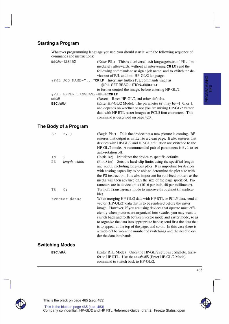
8/12/2019 HPGL2-RTL ReferenceGuide 5961-3526 540pages Sep96
http://slidepdf.com/reader/full/hpgl2-rtl-referenceguide-5961-3526-540pages-sep96 483/539
465
This is the black on page 465 (seq: 483)
Company confidential. HP-GL/2 and HP RTL Reference Guide, draft 2. Freeze Status: open
Starting a Program
Whatever programming language you use, you should start it with the following sequence of
commands and instructions:%–12345X (Enter PJL) This is a universal exit language/start of PJL. Im-
mediately afterwards, without an intervening , send the
following commands to assign a job name, and to switch the de-
vice out of PJL and into HP-GL/2 language:
@PJL JOB NAME=“...” Insert any further PJL commands, such as
@PJL SET RESOLUTION=600
to further control the image, before entering HP-GL/2.
@PJL ENTER LANGUAGE=HPGL2
E (Reset) Reset HP-GL/2 and other defaults.
%#B (Enter HP-GL/2 Mode). The parameter (#) may be –1, 0, or 1,
and depends on whether or not you are mixing HP-GL/2 vector
data with HP RTL raster images or PCL5 font characters. Thiscommand is described on page 420.
The Body of a Program
BP 5,1; (Begin Plot) Tells the device that a new picture is coming. BP
ensures that output is written to a clean page. It also ensures that
devices with HP-GL/2 and HP-GL emulation are switched to the
HP-GL/2 mode. A recommended pair of parameters is 5,1 to set
auto-rotation off.
IN ; (Initialize) Initializes the device to specific defaults.
PS length, width; (Plot Size) Sets the hard-clip limits using the specified length
and width, including long-axis plots. It is important for devices
with nesting capability to be able to determine the plot size withthe PS instruction. It is also important for roll-feed plotters as the
media will then advance only the size of the page specified. Pa-
rameters are in device units (1016 per inch, 40 per millimeter).
TR 0; Turn off Transparency mode to improve throughput (if applica-
ble).
<vector data> When merging HP-GL/2 data with HP RTL or PCL5 data, send all
vector (HP-GL/2) data that is to be rendered before the raster
image. However, if you are using devices that operate most effi-
ciently when pictures are organized into swaths, you may want to
switch back and forth between vector mode and raster mode, so as
to organize the data into appropriate bands; send first the data that
is to appear at the top of the page, and so on. In this case there isa trade-off between the number of switchings and the need to or-
der the data into bands.
Switching Modes
%#A (Enter RTL Mode) Once the HP-GL/2 setup is complete, trans-
fer to HP RTL. Use the %#B (Enter HP-GL/2 Mode)
command to switch back to HP-GL/2.
This is the blue on page 465 (seq: 483)
T I P S
P R O G R A M M I N G
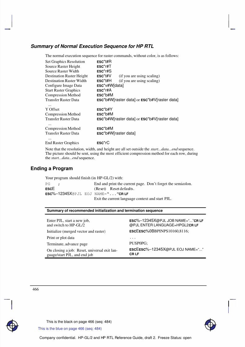
8/12/2019 HPGL2-RTL ReferenceGuide 5961-3526 540pages Sep96
http://slidepdf.com/reader/full/hpgl2-rtl-referenceguide-5961-3526-540pages-sep96 484/539
466
This is the black on page 466 (seq: 484)
Company confidential. HP-GL/2 and HP RTL Reference Guide, draft 2. Freeze Status: open
Summary of Normal Execution Sequence for HP RTL
The normal execution sequence for raster commands, without color, is as follows:
Set Graphics Resolution *t#RSource Raster Height *r#TSource Raster Width *r#SDestination Raster Height *t#V (if you are using scaling)Destination Raster Width *t#H (if you are using scaling)Configure Image Data *v#W[data]Start Raster Graphics *r#ACompression Method *b#MTransfer Raster Data *b#W[raster data] or *b#V[raster data] ...Y Offset *b#YCompression Method *b#MTransfer Raster Data *b#W[raster data] or *b#V[raster data] ...Compression Method *b#MTransfer Raster Data *b#W[raster data] ...End Raster Graphics *rC
Note that the resolution, width, and height are all set outside the start...data...end sequence.The picture should be sent, using the most efficient compression method for each row, duringthe start...data...end sequence.
Ending a Program
Your program should finish (in HP-GL/2) with:
PG ; End and print the current page. Don’t forget the semicolon.E (Reset) Reset defaults.
%–12345X@PJL EOJ NAME=“...”
Exit the current language context and start PJL.
Summary of recommended initialization and termination sequence
Enter PJL, start a new job,and switch to HP-GL/2
Initialize (merged vector and raster)
Print or plot data
Terminate, advance page
On closing a job: Reset, universal exit lan-guage/start PJL, and end job
%–12345X@PJL JOB NAME=“...”
@PJL ENTER LANGUAGE=HPGL2
E%0BBPINPS10160,8116;
...
PUSP0PG;E%–12345X@PJL EOJ NAME=“...”
This is the blue on page 466 (seq: 484)
8/12/2019 HPGL2-RTL ReferenceGuide 5961-3526 540pages Sep96
http://slidepdf.com/reader/full/hpgl2-rtl-referenceguide-5961-3526-540pages-sep96 485/539
467
This is the black on page 467 (seq: 485)
Company confidential. HP-GL/2 and HP RTL Reference Guide, draft 2. Freeze Status: open
Using HP-GL/2 Instructions and HP RTL Commands
Not all devices interpret all commands and instructions in the same way. See The Product Comparison Guide for HP Languages on HP Plotters and Large-Format Printers for device-de-pendencies.
NOP’d Instructions and Commands
Be aware of any instructions and commands that are ignored by your target devices.
Combined Commands
In HP RTL, combined commands are shorter than commands spelled out separately; the shortercommands require less data transmission time. See Combining Commands on page 340.
Output Instructions
Do not use HP-GL/2 output instructions to interrogate the device for information. Network andCentronics interface support becomes difficult, if not impossible, when information is requestedfrom the device.
Making Efficient Use of Your System
Here are some suggestions that may help you to create efficient graphics programs, includingdevice drivers.
Getting to Know HP-GL/2
Firstly, you should read through Chapters 2, 3, and 4 of this book. They explain the conceptsused by HP-GL/2. Try to get familiar with some of the simpler instructions in the Kernel.Look up their descriptions in the reference section of the book (Chapter 5). These descriptionscontain many examples of partial programs that use the instructions being defined.
If you see unfamiliar instructions, find the instruction description in the reference part of thebook and read about the instruction; instructions are listed alphabetically by their two-charactermnemonics. Think of an application that you would like to program and then look for an ex-ample that uses some of the elements you desire. After trying some examples and seeing howthe instructions interact, you should be well on your way to learning the HP-GL/2 language.
HP-GL/2 Vector Graphics There are different approaches (instructions) and techniques that can be used to create an HP-GL/2 picture. To assist in determining the most efficient approach to creating an image, severalpoints are identified below:
When you use line caps and joins:
– Most efficient – round join with butt cap
– Least efficient – round join with triangular cap.
This is the blue on page 467 (seq: 485)
T I P S
P R O G R A M M I N G
This is the blue on page 467 (seq: 485)This is the blue on page 467 (seq: 485)
8/12/2019 HPGL2-RTL ReferenceGuide 5961-3526 540pages Sep96
http://slidepdf.com/reader/full/hpgl2-rtl-referenceguide-5961-3526-540pages-sep96 486/539
468
This is the black on page 468 (seq: 486)
Company confidential. HP-GL/2 and HP RTL Reference Guide, draft 2. Freeze Status: open
When you use text, if you want the character to be printed at the same location as it wouldin PCL, use label origin position 21.
Default pen widths (5 dots wide or less) produce the highest speed.
Hewlett-Packard recommends using polygon mode when the number of points in a polygonis 1000 or less.
The Polyline Encoded instruction can reduce data by 60% to 70%.
When drawing shapes, use a instruction that was designed to draw that shape. For exam-ple, to draw a rectangle, use the ER instruction to produce it, instead of stroking the shapeline by line.
When drawing arcs or circles, use the Bezier instructions to eliminate the need to computethe chord angle, thus resulting in better quality and efficiency.
To Scale text, use the HP-GL/2 font selection commands, such as SD or AD, that useIntellifont or TrueType to scale the text. Scaling text in HP-GL/2, using the SR or SIinstructions, is much less efficient.
Font transformations in HP-GL/2, such as mirroring, scaling, slanting, rotating, and outlin-ing are very processing intensive. An ERROR 21 (print overrun) may occur. The error canbe controlled by using the HP LaserJet Page Protection feature, if available.
Automatic Pen Down
The following instructions include an automatic pen down as part of their function. After com-pleting their function, they restore the pen to its previous state (up or down). For moreinformation, see page 23.
CI, EA, EP, ER, EW, FP, LB, RA, RR, SM, WG.
“Lost” Mode
The pen position may sometimes become unknown to the device. This can happen as a resultof scaling. It is known as “lost” mode. See page 23 for more information.
Current Location
The following instructions update the current location. See page 66 for more information.
AA, AR, AT, BR, BZ, DF, DI, DR, DV, IN, LO, PA, PD, PE, PR, PU, RO, and RT.
Appearance of Characters
To obtain the most typographically correct characters, use “SI;” to disable graphic transforma-
tions, so that characters will be as close as possible to what the font designer intended. Sizewill be based solely on parameters last specified by AD or SD. If special graphic effects aredesired, such as rubbering or mirroring of characters, enable graphic transformations with SIand SR.
8/12/2019 HPGL2-RTL ReferenceGuide 5961-3526 540pages Sep96
http://slidepdf.com/reader/full/hpgl2-rtl-referenceguide-5961-3526-540pages-sep96 487/539
469
This is the black on page 469 (seq: 487)
Company confidential. HP-GL/2 and HP RTL Reference Guide, draft 2. Freeze Status: open
Performance
The printing speed will vary with the performance of the sending computer and the complexity
of the picture being sent. In general the objective is to get the total processing and transmissiontimes below the print time. Care should be taken when selecting:
The type and performance of the driving computer.
Choice of I/O system (Centronics, Bi-Tronics, RS-232, Networking, and so on).
HP RTL raster mode: 24-bit/pixel RGB, 1-bit/pixel Mono, 3-bit/pixel RGB or CMY or
4-bit/pixel KCMY.
In HP RTL, the scaling factor.
In HP RTL, the data compression technique used.
Transparency modes. In HP RTL, set both the source and pattern transparency modes to
opaque where possible.
Host Computer Resources
Consider scaling images at the host computer instead of in the device. Which method is bestdepends on available host resources, page size, image complexity, and the scale factor. Com-parative testing should look at host processing time, data transmission time, and deviceprocessing time.
Memory Size
In normal operation graphical objects sent to the device are stored in memory until the com-plete image has been sent. The amount of memory needed for an image will depend on the
number and type of the objects and how well the device can compress them internally. Picturescontaining a lot of images or detailed drawings will use more memory. Printing will automati-cally begin when the memory is full.
When printing images it is often useful to disable this feature by sending the HP RTL commandto prevent Negative Motion (&a1N). This saves memory, and printing will start as soon asthe first rows of data have been received. Only images that do not move the current activeposition (CAP) up the page can use this mode.
Configure Image Data Command
The Configure Image Data command has implications on the kind of data generated in the de-vice, and although it is device-dependent, there are some general guidelines on memory
requirements. The fastest method is direct selection using three planes; monochrome is nextefficient, followed by direct selection by pixel with default black and white reference values;Simple Color mode is also efficient; all other methods are generally less efficient.
PCL Commands
Since PCL printers are command driven devices and each command takes a finite amount of time to process, pages composed of a large number of commands may not print at maximumspeed. Most commands can be used frequently on a page without adversely affecting the print-
This is the blue on page 469 (seq: 487)
T I P S
P R O G R A M M I N G
8/12/2019 HPGL2-RTL ReferenceGuide 5961-3526 540pages Sep96
http://slidepdf.com/reader/full/hpgl2-rtl-referenceguide-5961-3526-540pages-sep96 488/539
470
This is the black on page 470 (seq: 488)
Company confidential. HP-GL/2 and HP RTL Reference Guide, draft 2. Freeze Status: open
er’s performance; however, certain commands take more time to process and therefore, if usedfrequently on a page, may decrease printer performance. An excessive number of font selec-tions per page (selection using font characteristic commands or selection by ID number) may
decrease printer performance.
Print Data
There is a limit on the amount of data, as well as the number of commands, that the printer canprocess per page at maximum speed.
Print Overrun
As data is received by the printer, it is processed and stored in an intermediate format. Theintermediate data is later processed and printed. During the physical printing of a page, thepage moves through the printer at a constant speed. Thus, some pages cannot be printed be-cause the page’s intermediate data cannot be processed fast enough to keep up with the physical
speed of the page as it moves through the printer. When this condition occurs, an error number‘‘21’’ (‘‘ERROR 21’’ – print overrun) is displayed on the printer’s control panel. A page caus-ing this error can be printed by setting the printer’s page protection feature to ON (see nextsection).
Page Protection
If enabled, page protection reserves an amount of memory for the page image process, allowingthe printer to create the entire page image (in memory) before physically moving the paperthrough the printer.
Note: The page protection feature is available only with additional optional memory on manyHP LaserJet printers. (One exception is the LaserJet 4 printer, which supports page protectionfor letter-size paper in 300 dpi mode with the standard 2 Mbytes memory.) Refer to the ap-propriate User’s Manual for specific memory requirements.
The Page Protection feature can be used to prevent possible ‘‘ERROR 21’’ conditions. ‘‘ER-ROR 21’’ is reported when data is too complex for the device to process concurrent with actualphysical printing. A frequent cause of ‘‘ERROR 21’’ when printing graphics is that the pro-gram sends commands to print a single point many times during the page run.
Page protection can be set for letter, A4, or legal sized pages. Set page protection for the pagesize most often used.
Input/Output
The throughput of your device is the time it takes to complete a page. To take full advantage of your peripheral’s speed, use a parallel interface, such as Centronics or HP-IB. For the bestthroughput with an RS-232-C interface, use the highest baud rate the device supports.
Parallel and network communications interfaces provide the fastest data transmission times.This is particularly important when transmitting raster data. However, if you use the RS-232-Cserial interface, turn parity checking off at the device. If parity checking is on, the eighth bit of each byte is used as a check bit, which is inconsistent with raster data.
The parallel (Centronics) interface has higher throughput than the RS-232-C serial I/O. Rastergraphics processing will usually benefit from increased I/O throughput.
This is the blue on page 470 (seq: 488)
8/12/2019 HPGL2-RTL ReferenceGuide 5961-3526 540pages Sep96
http://slidepdf.com/reader/full/hpgl2-rtl-referenceguide-5961-3526-540pages-sep96 489/539
471
This is the black on page 471 (seq: 489)
Company confidential. HP-GL/2 and HP RTL Reference Guide, draft 2. Freeze Status: open
Page Layout and Positioning
How you present information on the page may have a bearing on the programming techniquesused.
Page Orientation and Size
HP RTL orientation is portrait; HP-GL/2 has the X-axis along the larger axis, and the Y-axisalong the shorter axis. See The Coordinate System on page 7.
If the user specifies page size in inches, the driver multiplies the size by 1016; if specified inmillimeters, by 40. Then use the PS instruction to specify the page size.
Area of the Output
Some devices have a built-in default for the size of their output. This can be set smaller bychanging options on the control panel of the device. To make pictures longer than these sizes itis necessary to set the plot size using the HP-GL/2 PS (Plot Size) instruction.
The PS (Plot Size) instruction currently specified for HP-GL/2 mode is automatically importedinto HP RTL mode; the logical page size is set to the hard-clip limits. The IW (Input Window)specified for HP-GL/2 mode is also imported into HP RTL mode. Vector and raster images areclipped to the window area.
Zero Filling
By using source raster width and height, you can avoid sending unnecessary “blank” data forborders. You can also use the Y Offset command to skip over rows that should be left zero,thus creating a background. See Using Index 0 on page 359.
Moving the Current Active Position
There are four commands that set the CAP position in HP RTL (the current active position):
Move CAP Horizontal (native HP RTL units) *p#X
Move CAP Vertical (native HP RTL units) *p#Y
Move CAP Horizontal (decipoints) &a#H
Y Offset (pixels) *b#Y
The Y Offset command (when in non-raster mode) and Move CAP Horizontal (Decipoints)
command are to be made obsolete, so you should not use them in new application programs.
This is the blue on page 471 (seq: 489)
T I P S
P R O G R A M M I N G
8/12/2019 HPGL2-RTL ReferenceGuide 5961-3526 540pages Sep96
http://slidepdf.com/reader/full/hpgl2-rtl-referenceguide-5961-3526-540pages-sep96 490/539
472
This is the black on page 472 (seq: 490)
Company confidential. HP-GL/2 and HP RTL Reference Guide, draft 2. Freeze Status: open
Preparing Your Data
How you send data to the device has a significant effect on the overall performance of yourplotting or printing system.
Raster Graphics
To minimize I/O transmission time and conserve memory, avoid sending to the device unneces-sary raster data that represents white space. This is accomplished using the raster compressionmodes and raster reduction techniques available.
Set the resolution before the Start Raster Graphics command. Once this command is received,the resolution cannot be changed until after an End Raster Graphics command is issued.
Some applications and I/O drivers insert carriage returns and line feeds into the data stream sentto the printer. This modification of data must be suppressed for correct operation with HP RTL.
The most efficient way to draw lines (horizontal, vertical, and diagonal) and polygons is usingHP-GL/2 vector graphics.
Data Compression
Mix compression methods to get the most efficient transmission. See Compressing Data onpage 380. If you are using TIFF Packbits encoding, see the note in that section on when to en-code data and when to send literal data.
There are seven compression methods available that will considerably improve throughput, andtwo methods of sending uncompressed raster data. The amount of compression that can beachieved varies considerably with the type of data being sent. Large areas of color compresswell whereas images with a lot of detail do not. We recommend your driver should try eachcompression mode on each row of data and send the one that turns out to be smallest. (Note:Compression modes 6, 7 and 8 are for monochrome only.)
Sending Raster Data
Raster data is printed a row at a time. Avoid using the negative Y Offset command (*b#Y)as this requires a significant amount of additional memory for the device to handle the move.If you do not use negative motion and you are not sending any vector data, you can indicatethis using &a1N and printing begins immediately (on-the-fly) with the first row of rasterdata the device receives.
Merged Vector and Raster Data
When you use both HP RTL and HP-GL/2 in an application program, you should try to mini-mize the number of switches of context between these two environments. Note that the paletteis transferred when you switch environments.
Vectors could be given first priority in occupying memory space with whatever is left over forraster data. Vector and raster data are treated on a first-in-first-out basis. The bottom portion of raster data sent could be lost if the combined vectors and raster exceed the memory space. If multiple raster images are sent to the same page and the memory space is exceeded, printing
This is the blue on page 472 (seq: 490)
8/12/2019 HPGL2-RTL ReferenceGuide 5961-3526 540pages Sep96
http://slidepdf.com/reader/full/hpgl2-rtl-referenceguide-5961-3526-540pages-sep96 491/539
473
This is the black on page 473 (seq: 491)
Company confidential. HP-GL/2 and HP RTL Reference Guide, draft 2. Freeze Status: open
begins and all subsequent vector and raster images are ignored. The image that hit the limitwill be printed in its entirety.
You can merge vector and raster data as long as your vector and raster data take up less than theavailable memory. Although the vector data can be sent at any time, we strongly recommendyou send all the vector data first in case you run out of memory and so that raster printing canbegin on-the-fly. In situations where the device runs out of memory during HP RTL, the imagedata will be printed as long as the CAP position does not move backwards with respect to themotion of the paper. An alternative strategy is to arrange data into bands, for devices that usesuperflow mode (see “Superflow” Mode on page 379).
The interaction between the vector and raster data is determined in HP-GL/2 by the TR (Trans-parency Mode) instruction and in HP RTL by the Source Transparency (*v#N) command,and in both environments by the latest MC (Merge Control) instruction or Logical Operationcommand issued.
Merging HP-GL/2 and HP RTL data is not supported for KCMY data using the Simple Color(*r–4U) command.
Scaling Raster Images
HP RTL images can be enlarged or reduced by the device. To scale the image:
Set the Source Raster Width (*r#S) and Source Raster Height (*r#T) to the source
image size.
Set the Destination Raster Width (*t#H) and Destination Raster Height (*t#V) to
the new size.
Send the Start Raster Graphics (*r#A) command with parameter 2 or 3 (to enable scal-
ing.) The scale factor is implied by the relationship between source and destination sizes.Scaling is achieved by pixel replication.
Note that the HP-GL/2 scaling defined by the SC (Scale) command has no effect on HP RTLimages.
Transparency
In HP RTL, it is usually more efficient to explicitly set the transparency modes off initially, andthen to switch them on and off as required.
Using Color
Consider the following aspects of the use of color in your output.
KCMY Operation
When sending 4-bit/pixel KCMY output, it is possible to place up to 4 dots of ink per pixel onthe paper (it is normally limited to 2 dots). With some media types this may result in excessivewetting of the media and care should be taken when writing drivers to avoid these conditions.
This is the blue on page 473 (seq: 491)
T I P S
P R O G R A M M I N G
8/12/2019 HPGL2-RTL ReferenceGuide 5961-3526 540pages Sep96
http://slidepdf.com/reader/full/hpgl2-rtl-referenceguide-5961-3526-540pages-sep96 492/539
474
This is the black on page 474 (seq: 492)
Company confidential. HP-GL/2 and HP RTL Reference Guide, draft 2. Freeze Status: open
Color Palette Operations
HP-GL/2 and HP RTL can share one common (unified) palette. Palette entries can be modified
in either HP-GL/2 (NP, CR, PC) or HP RTL (*v#A, *v#B, *v#C, *v#I) com-mands. IN and BP always establish a default HP-GL/2 palette whose size is device-dependent.
The palette is copied from one context to another via the context-switch commands (%#Aand %#B). When a palette is imported, both its size and the colors of its entries areimported.
User Operations
Users can affect the way the device operates, by selecting options on the front control panel.However, a driver can override control-panel settings by using appropriate PJL commands (seepage 394).
Troubleshooting
Sometimes you may find that your printer or plotter produces results that you did not expect.First check in the device’s User’s Guide to see that the feature you want is supported. Othersoftware that you are using may also have documentation that you should check.
This is the blue on page 474 (seq: 492)This is the blue on page 474 (seq: 492)
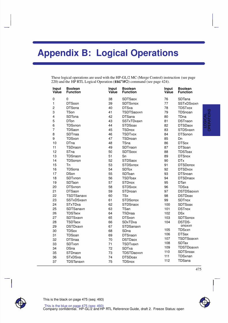
8/12/2019 HPGL2-RTL ReferenceGuide 5961-3526 540pages Sep96
http://slidepdf.com/reader/full/hpgl2-rtl-referenceguide-5961-3526-540pages-sep96 493/539
475
This is the black on page 475 (seq: 493)
Company confidential. HP-GL/2 and HP RTL Reference Guide, draft 2. Freeze Status: open
Appendix B: Logical Operations
These logical operations are used with the HP-GL/2 MC (Merge Control) instruction (see page220) and the HP RTL Logical Operation (*l#O) command (see page 424).
InputValue
BooleanFunction
0 0
1 DTSoon
2 DTSona
3 TSon4 SDTona
5 DTon
6 TDSxnon
7 TDSaon
8 SDTnaa
9 TDSxon
10 DTna
11 TSDnaon
12 STna
13 TDSnaon
14 TDSonon
15 Tn
16 TDSona17 DSon
18 SDTxnon
19 SDTaon
20 DTSxnon
21 DTSaon
22 TSDTSanaxx
23 SSTxDSxaxn
24 STxTDxa
25 SDTSanaxn
26 TDSTaox
27 SDTSxaxn
28 TSDTaox
29 DSTDxaxn30 TDSox
31 TDSoan
32 DTSnaa
33 SDTxon
34 DSna
35 STDnaon
36 STxDSxa
37 TDSTanaxn
InputValue
BooleanFunction
38 SDTSaox
39 SDTSxnox
40 DTSxa
41 TSDTSaoxxn42 DTSana
43 SSTxTDxaxn
44 STDSoax
45 TSDnox
46 TSDTxox
47 TSDnoan
48 TSna
49 SDTnaon
50 SDTSoox
51 Sn
52 STDSaox
53 STDSxnox
54 SDTox55 SDToan
56 TSDToax
57 STDnox
58 STDSxox
59 STDnoan
60 TSx
61 STDSonox
62 STDSnaox
63 TSan
64 TSDnaa
65 DTSxon
66 SDxTDxa
67 STDSanaxn68 SDna
69 DTSnaon
70 DSTDaox
71 TSDTxaxn
72 SDTxa
73 TDSTDaoxxn
74 DTSDoax
75 TDSnox
InputValue
BooleanFunction
76 SDTana
77 SSTxDSxoxn
78 TDSTxox
79 TDSnoan80 TDna
81 DSTnaon
82 DTSDaox
83 STDSxaxn
84 DTSonon
85 Dn
86 DTSox
87 DTSoan
88 TDSToax
89 DTSnox
90 DTx
91 DTSDonox
92 DTSDxox93 DTSnoan
94 DTSDnaox
95 DTan
96 TDSxa
97 DSTDSaoxxn
98 DSTDoax
99 SDTnox
100 SDTSoax
101 DSTnox
102 DSx
103 SDTSonox
104 DSTDS-
onoxxn105 TDSxxn
106 DTSax
107 TSDTSoaxxn
108 SDTax
109 TDSTDoaxxn
110 SDTSnoax
111 TDSxnan
112 TDSana
This is the blue on page 475 (seq: 493)
O P E R A T I O N
S
L O G I C A L
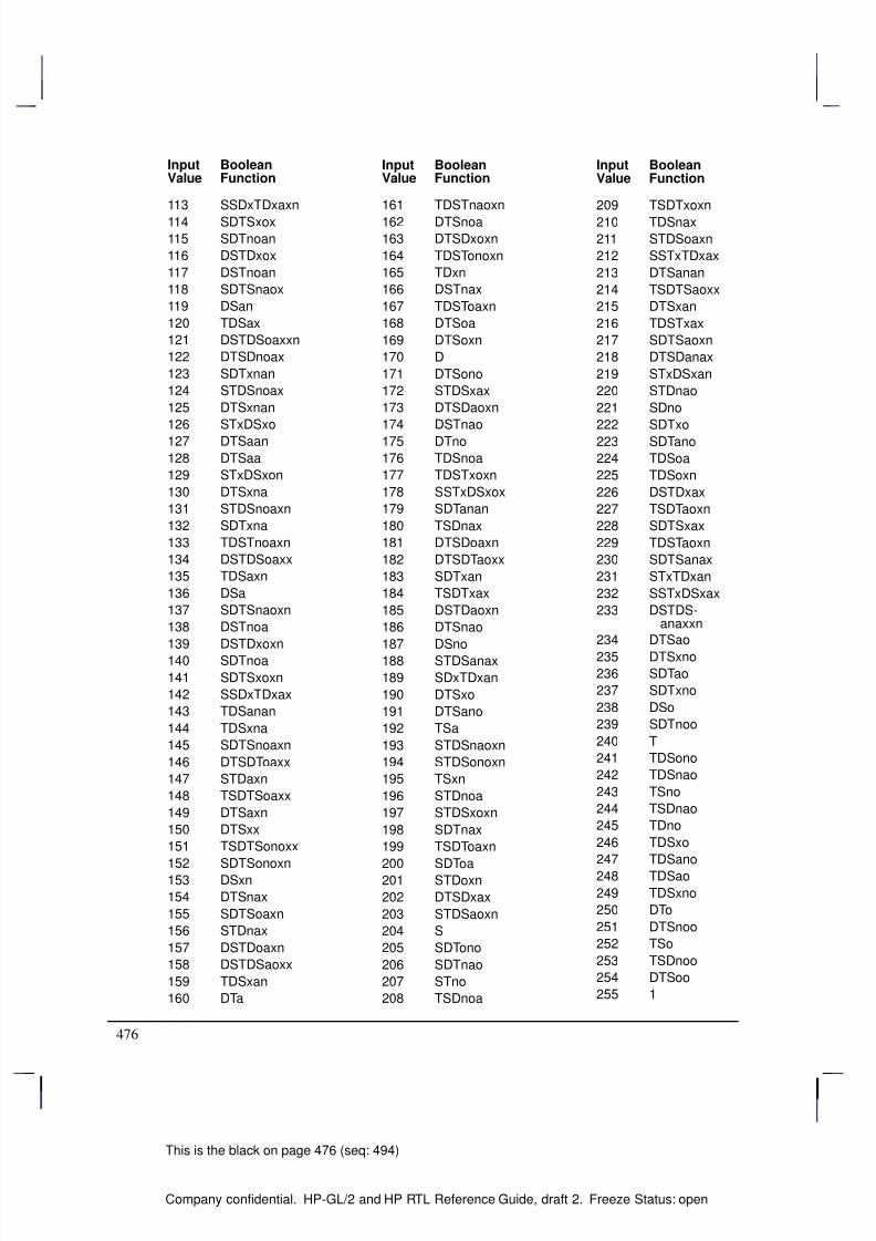
8/12/2019 HPGL2-RTL ReferenceGuide 5961-3526 540pages Sep96
http://slidepdf.com/reader/full/hpgl2-rtl-referenceguide-5961-3526-540pages-sep96 494/539
476
This is the black on page 476 (seq: 494)
Company confidential. HP-GL/2 and HP RTL Reference Guide, draft 2. Freeze Status: open
InputValue
BooleanFunction
113 SSDxTDxaxn
114 SDTSxox
115 SDTnoan
116 DSTDxox
117 DSTnoan
118 SDTSnaox
119 DSan
120 TDSax
121 DSTDSoaxxn
122 DTSDnoax
123 SDTxnan
124 STDSnoax
125 DTSxnan
126 STxDSxo
127 DTSaan
128 DTSaa
129 STxDSxon
130 DTSxna
131 STDSnoaxn
132 SDTxna
133 TDSTnoaxn
134 DSTDSoaxx
135 TDSaxn
136 DSa
137 SDTSnaoxn
138 DSTnoa
139 DSTDxoxn
140 SDTnoa
141 SDTSxoxn
142 SSDxTDxax
143 TDSanan
144 TDSxna
145 SDTSnoaxn
146 DTSDToaxx
147 STDaxn
148 TSDTSoaxx
149 DTSaxn
150 DTSxx
151 TSDTSonoxx
152 SDTSonoxn153 DSxn
154 DTSnax
155 SDTSoaxn
156 STDnax
157 DSTDoaxn
158 DSTDSaoxx
159 TDSxan
160 DTa
InputValue
BooleanFunction
161 TDSTnaoxn
162 DTSnoa
163 DTSDxoxn
164 TDSTonoxn
165 TDxn
166 DSTnax
167 TDSToaxn
168 DTSoa
169 DTSoxn
170 D
171 DTSono
172 STDSxax
173 DTSDaoxn
174 DSTnao
175 DTno
176 TDSnoa
177 TDSTxoxn
178 SSTxDSxox
179 SDTanan
180 TSDnax
181 DTSDoaxn
182 DTSDTaoxx
183 SDTxan
184 TSDTxax
185 DSTDaoxn
186 DTSnao
187 DSno
188 STDSanax
189 SDxTDxan
190 DTSxo
191 DTSano
192 TSa
193 STDSnaoxn
194 STDSonoxn
195 TSxn
196 STDnoa
197 STDSxoxn
198 SDTnax
199 TSDToaxn
200 SDToa201 STDoxn
202 DTSDxax
203 STDSaoxn
204 S
205 SDTono
206 SDTnao
207 STno
208 TSDnoa
InputValue
BooleanFunction
209 TSDTxoxn
210 TDSnax
211 STDSoaxn
212 SSTxTDxax
213 DTSanan
214 TSDTSaoxx
215 DTSxan
216 TDSTxax
217 SDTSaoxn
218 DTSDanax
219 STxDSxan
220 STDnao
221 SDno
222 SDTxo
223 SDTano
224 TDSoa
225 TDSoxn
226 DSTDxax
227 TSDTaoxn
228 SDTSxax
229 TDSTaoxn
230 SDTSanax
231 STxTDxan
232 SSTxDSxax
233 DSTDS- anaxxn
234 DTSao
235 DTSxno236 SDTao
237 SDTxno
238 DSo
239 SDTnoo
240 T
241 TDSono
242 TDSnao
243 TSno
244 TSDnao
245 TDno
246 TDSxo
247 TDSano
248 TDSao
249 TDSxno
250 DTo
251 DTSnoo
252 TSo
253 TSDnoo
254 DTSoo
255 1
8/12/2019 HPGL2-RTL ReferenceGuide 5961-3526 540pages Sep96
http://slidepdf.com/reader/full/hpgl2-rtl-referenceguide-5961-3526-540pages-sep96 495/539
477
This is the black on page 477 (seq: 495)
Company confidential. HP-GL/2 and HP RTL Reference Guide, draft 2. Freeze Status: open
Appendix C: Font Definitions
The font definitions in this Appendix apply to the kind and value parameters of the AD (AlternateFont Definition) and SD (Standard Font Definition) instructions of HP-GL/2. See pages 106 and296 respectively.
Kind 1: Symbol Set
The symbol set characteristic defines the set of characters to be used in the standard (SD) or alter-nate (AD) font. These values are listed in order of the PCL identification.
Note: Stick font is available only in ASCII, Roman-8, and Roman Extension symbol sets.
ValuesDescription andSymbol Set ID
0 (and 277) Default Set Roman-8 [8U]
1 Math-7* [0A]
2 Line Draw-7* [0B]
3 HP Large Characters (264x Terminals)* [0C]
4 Danish/Norwegian ver-sion 1 (ISO 60) [0D]
36 Norwegian Version 2 [1D]
5 Roman Extensions* [0E]
6 French (ISO 25)* [0F]
37 United Kingdom (ISO 4) [1E]
38 French (ISO 69) [1F]
39 German (ISO 21) [1G]
263 Greek-8 [8G]
8 Hebrew-7 [0H]
264 Hebrew-8 [8H]
9 Italian (ISO 15) [0I]
202 Microsoft Publishing [6J]
234 DeskTop [7J]330 PS Text [10J]
426 Ventura International [13J]
458 Ventura US [14J]
11 JIS ASCII* (ISO 14) [0K]
43 Katakana* (ISO 13) [1K]
267 Kana-8 [8K]
ValuesDescription andSymbol Set ID
299 Korean-8 [9K]
1611 JIS Kanji-1 [50K]
1643 JIS Kanji-2 [51K]
12 Line Draw-7 [0L]
44 HP Block Characters [1L]
76 Tax Line Draw [2L]
268 Line Draw-8 [8L]300 Ventura ITC Zapf Dingbats [9L]
332 PS ITC Zapf Dingbats [10L]
364 ITC Zapf Dingbats Series 100 [11L]
396 ITC Zapf Dingbats Series 200 [12L]
428 ITC Zapf Dingbats Series 300 [13L]
13 Math-7 [0M]
45 Tech-7 (DEC) [1M]
173 PS Math [5M]
205 Ventura Math [6M]269 Math-8 [8M]
14 ECMA-94 Latin 1 (8-bit version; ISO 8859/1) [0N]
78 ECMA-94 Latin 2 (ISO 8859/2) [2N]
174 ECMA-128 Latin 5 (ISO 8859/9) [5N]
This is the blue on page 477 (seq: 495)
D E F I N I T I O N S
F O N T
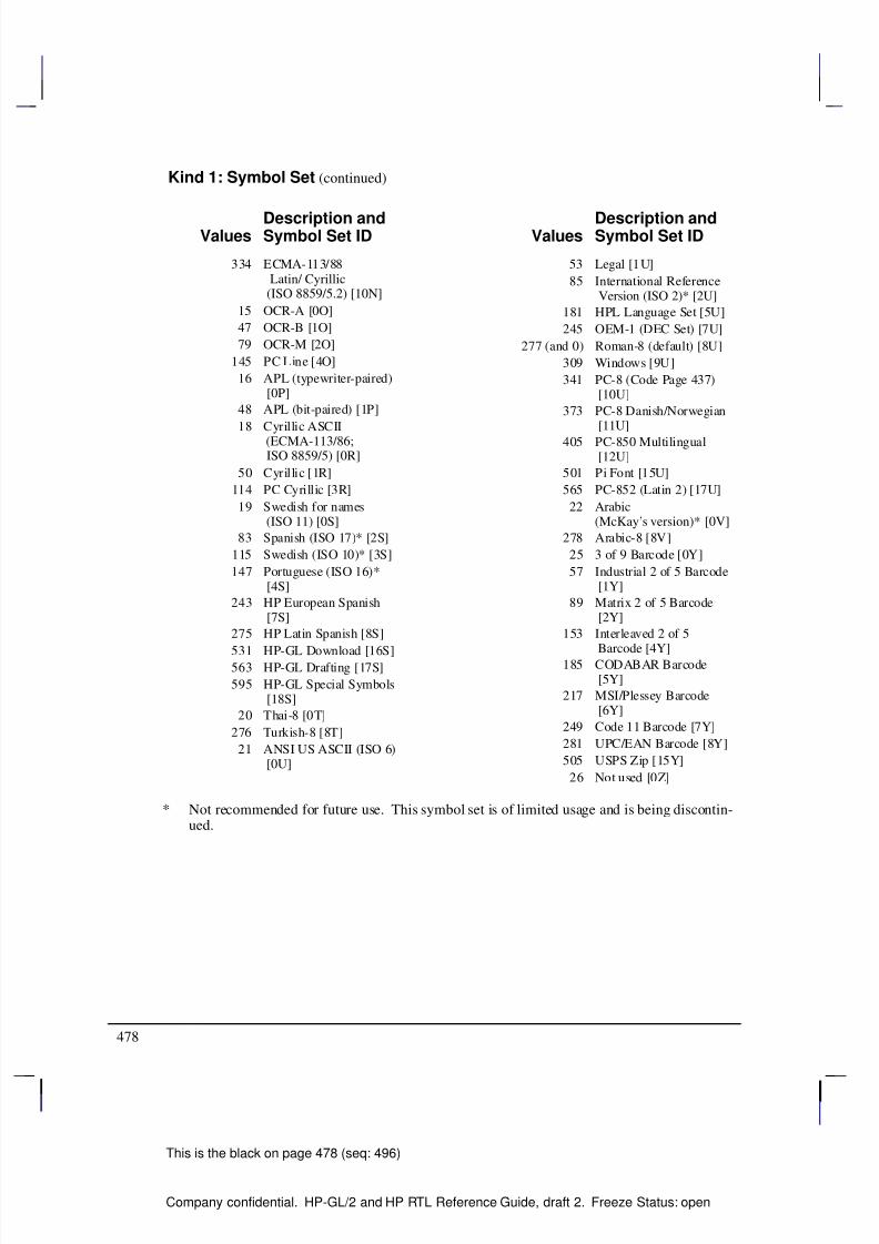
8/12/2019 HPGL2-RTL ReferenceGuide 5961-3526 540pages Sep96
http://slidepdf.com/reader/full/hpgl2-rtl-referenceguide-5961-3526-540pages-sep96 496/539
478
This is the black on page 478 (seq: 496)
Company confidential. HP-GL/2 and HP RTL Reference Guide, draft 2. Freeze Status: open
Kind 1: Symbol Set (continued)
ValuesDescription andSymbol Set ID
334 ECMA-113/88 Latin/ Cyrillic(ISO 8859/5.2) [10N]
15 OCR-A [0O]
47 OCR-B [1O]
79 OCR-M [2O]
145 PC Line [4O]
16 APL (typewriter-paired) [0P]
48 APL (bit-paired) [1P]
18 Cyrillic ASCII (ECMA-113/86; ISO 8859/5) [0R]
50 Cyrillic [1R]
114 PC Cyrillic [3R]
19 Swedish for names (ISO 11) [0S]
83 Spanish (ISO 17)* [2S]
115 Swedish (ISO 10)* [3S]
147 Portuguese (ISO 16)* [4S]
243 HP European Spanish [7S]
275 HP Latin Spanish [8S]
531 HP-GL Download [16S]563 HP-GL Drafting [17S]
595 HP-GL Special Symbols [18S]
20 Thai-8 [0T]
276 Turkish-8 [8T]
21 ANSI US ASCII (ISO 6) [0U]
ValuesDescription andSymbol Set ID
53 Legal [1U]
85 International Reference Version (ISO 2)* [2U]
181 HPL Language Set [5U]
245 OEM-1 (DEC Set) [7U]
277 (and 0) Roman-8 (default) [8U]
309 Windows [9U]
341 PC-8 (Code Page 437) [10U]
373 PC-8 Danish/Norwegian [11U]
405 PC-850 Multilingual [12U]
501 Pi Font [15U]
565 PC-852 (Latin 2) [17U]
22 Arabic(McKay’s version)* [0V]
278 Arabic-8 [8V]
25 3 of 9 Barcode [0Y]
57 Industrial 2 of 5 Barcode [1Y]
89 Matrix 2 of 5 Barcode [2Y]
153 Interleaved 2 of 5
Barcode [4Y]185 CODABAR Barcode [5Y]
217 MSI/Plessey Barcode [6Y]
249 Code 11 Barcode [7Y]
281 UPC/EAN Barcode [8Y]
505 USPS Zip [15Y]
26 Not used [0Z]
* Not recommended for future use. This symbol set is of limited usage and is being discontin-ued.
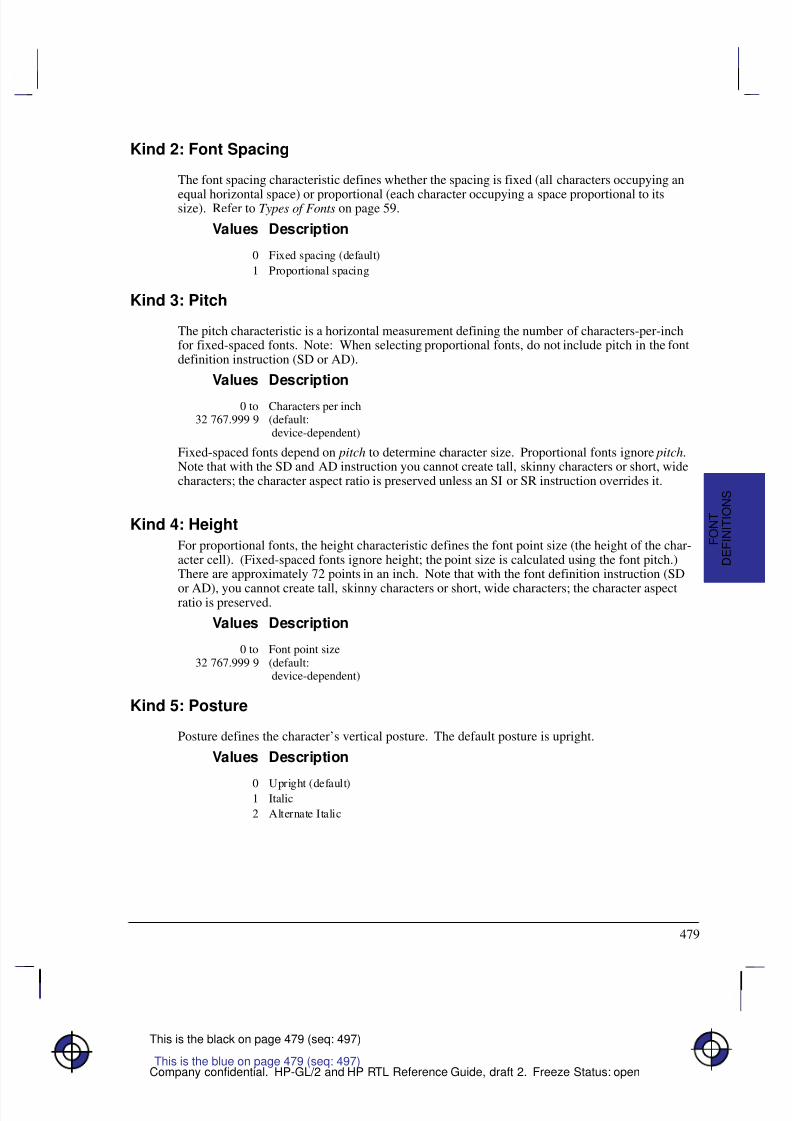
8/12/2019 HPGL2-RTL ReferenceGuide 5961-3526 540pages Sep96
http://slidepdf.com/reader/full/hpgl2-rtl-referenceguide-5961-3526-540pages-sep96 497/539
479
This is the black on page 479 (seq: 497)
Company confidential. HP-GL/2 and HP RTL Reference Guide, draft 2. Freeze Status: open
Kind 2: Font Spacing
The font spacing characteristic defines whether the spacing is fixed (all characters occupying an
equal horizontal space) or proportional (each character occupying a space proportional to itssize). Refer to Types of Fonts on page 59.
Values Description
0 Fixed spacing (default)
1 Proportional spacing
Kind 3: Pitch
The pitch characteristic is a horizontal measurement defining the number of characters-per-inchfor fixed-spaced fonts. Note: When selecting proportional fonts, do not include pitch in the fontdefinition instruction (SD or AD).
Values Description
0 to32 767.999 9
Characters per inch(default: device-dependent)
Fixed-spaced fonts depend on pitch to determine character size. Proportional fonts ignore pitch.Note that with the SD and AD instruction you cannot create tall, skinny characters or short, widecharacters; the character aspect ratio is preserved unless an SI or SR instruction overrides it.
Kind 4: Height
For proportional fonts, the height characteristic defines the font point size (the height of the char-acter cell). (Fixed-spaced fonts ignore height; the point size is calculated using the font pitch.)There are approximately 72 points in an inch. Note that with the font definition instruction (SD
or AD), you cannot create tall, skinny characters or short, wide characters; the character aspectratio is preserved.
Values Description
0 to32 767.999 9
Font point size(default: device-dependent)
Kind 5: Posture
Posture defines the character’s vertical posture. The default posture is upright.
Values Description
0 Upright (default)1 Italic
2 Alternate Italic
D E F I N I T I O N S
F O N T
This is the blue on page 479 (seq: 497)
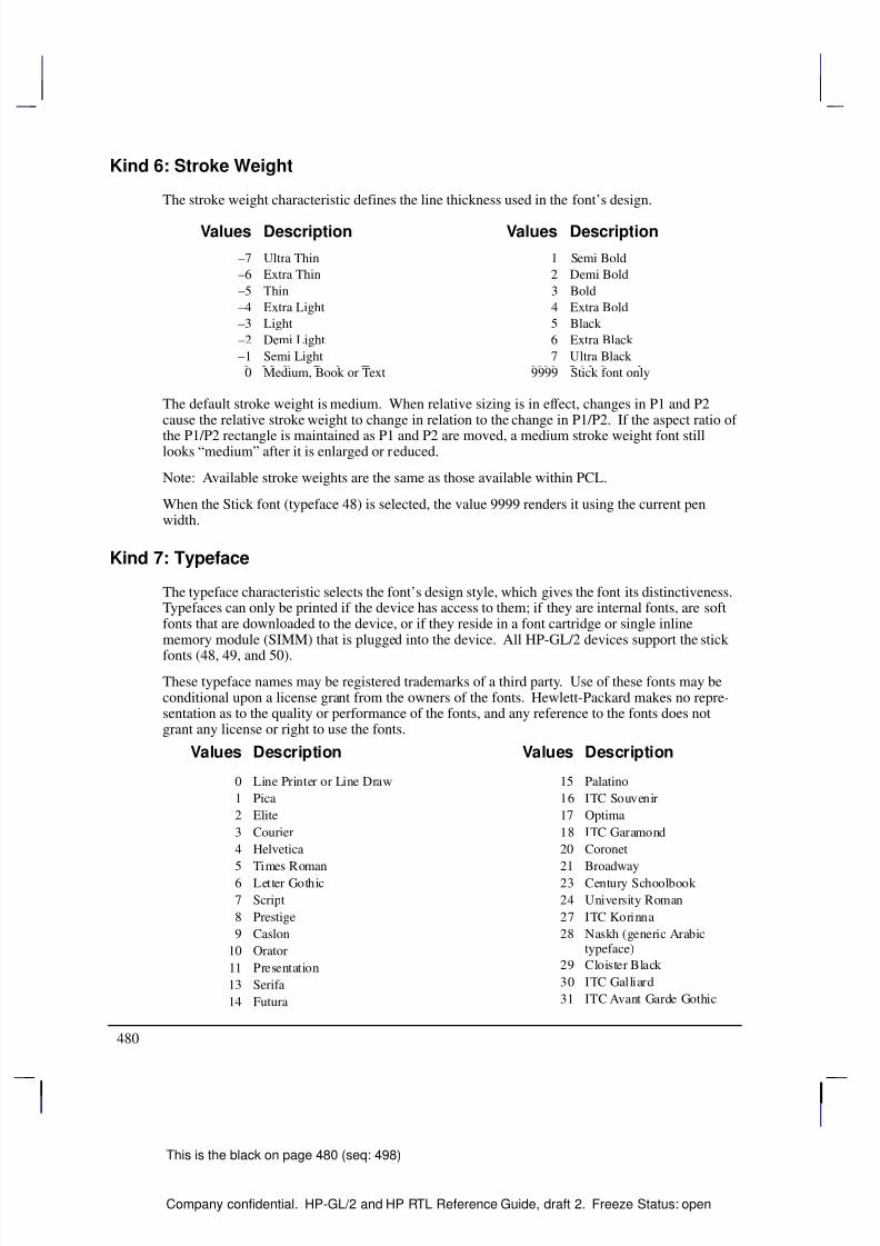
8/12/2019 HPGL2-RTL ReferenceGuide 5961-3526 540pages Sep96
http://slidepdf.com/reader/full/hpgl2-rtl-referenceguide-5961-3526-540pages-sep96 498/539
480
This is the black on page 480 (seq: 498)
Company confidential. HP-GL/2 and HP RTL Reference Guide, draft 2. Freeze Status: open
Kind 6: Stroke Weight
The stroke weight characteristic defines the line thickness used in the font’s design.
Values Description Values Description
–7 Ultra Thin 1 Semi Bold
–6
Extra Thin 2
Demi Bold
–5 Thin 3 Bold
–4 Extra Light 4 Extra Bold
–3 Light 5 Black
–2 Demi Light 6 Extra Black
–1 Semi Light 7 Ultra Black
0 Medium, Book or Text 9999 Stick font only
The default stroke weight is medium. When relative sizing is in effect, changes in P1 and P2cause the relative stroke weight to change in relation to the change in P1/P2. If the aspect ratio of
the P1/P2 rectangle is maintained as P1 and P2 are moved, a medium stroke weight font stilllooks “medium” after it is enlarged or reduced.
Note: Available stroke weights are the same as those available within PCL.
When the Stick font (typeface 48) is selected, the value 9999 renders it using the current penwidth.
Kind 7: Typeface
The typeface characteristic selects the font’s design style, which gives the font its distinctiveness.Typefaces can only be printed if the device has access to them; if they are internal fonts, are softfonts that are downloaded to the device, or if they reside in a font cartridge or single inlinememory module (SIMM) that is plugged into the device. All HP-GL/2 devices support the stick
fonts (48, 49, and 50).
These typeface names may be registered trademarks of a third party. Use of these fonts may beconditional upon a license grant from the owners of the fonts. Hewlett-Packard makes no repre-sentation as to the quality or performance of the fonts, and any reference to the fonts does notgrant any license or right to use the fonts.
Values Description
0 Line Printer or Line Draw
1 Pica
2 Elite
3 Courier
4 Helvetica
5 Times Roman
6 Letter Gothic
7 Script
8 Prestige
9 Caslon
10 Orator
11 Presentation
13 Serifa
14 Futura
Values Description
15 Palatino
16 ITC Souvenir
17 Optima
18 ITC Garamond
20 Coronet
21 Broadway
23 Century Schoolbook
24 University Roman
27 ITC Korinna
28 Naskh (generic Arabictypeface)
29 Cloister Black
30 ITC Galliard
31 ITC Avant Garde Gothic
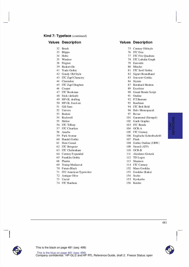
8/12/2019 HPGL2-RTL ReferenceGuide 5961-3526 540pages Sep96
http://slidepdf.com/reader/full/hpgl2-rtl-referenceguide-5961-3526-540pages-sep96 499/539
481
This is the black on page 481 (seq: 499)
Company confidential. HP-GL/2 and HP RTL Reference Guide, draft 2. Freeze Status: open
Kind 7: Typeface (continued)
Values Description
32 Brush
33 Blippo
34 Hobo
35 Windsor
38 Peignot
39 Baskerville
41 Trade Gothic
42 Goudy Old Style
43 ITC Zapf Chancery
44 Clarendon
45 ITC Zapf Dingbats
46 Cooper
47 ITC Bookman48 Stick (default)
49 HP-GL drafting
50 HP-GL fixed arc
51 Gill Sans
52 Univers
53 Bodoni
54 Rockwell
55 Melior
56 ITC Tiffany
57 ITC Clearface
58 Amelia
59 Park Avenue
60 Handel Gothic61 Dom Casual
62 ITC Benguiat
63 ITC Cheltenham
64 Century Expanded
65 Franklin Gothic
68 Plantin
69 Trump Mediaeval
70 Futura Black
71 ITC American Typewriter
72 Antique Olive
73 Uncial
74 ITC Bauhaus
Values Description
75 Century Oldstyle
76 ITC Eras
77 ITC Friz Quadrata
78 ITC Lubalin Graph
79 Eurostile
80 Mincho
81 ITC Serif Gothic
82 Signet Roundhand
83 Souvenir Gothic
84 Stymie
87 Bernhard Modern
89 Excelsior
90 Grand Ronde Script91 Ondine
92 P.T.Barnum
93 Kaufman
94 ITC Bolt Bold
96 Helv Monospaced
97 Revue
101 Garamond (Stempel)
102 Garth Graphic
103 ITC Ronda
104 OCR-A
105 ITC Century
106 Englische Schreibschrift
107 Flash108 Gothic Outline (URW)
109 Stensil (ATF)
110 OCR-B
111 Akzidenz-Grotesk
112 TD Logos
113 Shannon
114 ITC Century
152 Maru Gosikku
153 Gosikku (Kaku)
154 Socho
155 Kyokasho
156 Kaisho
D E F I N I T I O N S
F O N T
This is the blue on page 481 (seq: 499)

8/12/2019 HPGL2-RTL ReferenceGuide 5961-3526 540pages Sep96
http://slidepdf.com/reader/full/hpgl2-rtl-referenceguide-5961-3526-540pages-sep96 500/539
482
This is the black on page 482 (seq: 500)
Company confidential. HP-GL/2 and HP RTL Reference Guide, draft 2. Freeze Status: open
8/12/2019 HPGL2-RTL ReferenceGuide 5961-3526 540pages Sep96
http://slidepdf.com/reader/full/hpgl2-rtl-referenceguide-5961-3526-540pages-sep96 501/539
483
This is the black on page 483 (seq: 501)
Company confidential. HP-GL/2 and HP RTL Reference Guide, draft 2. Freeze Status: open
Glossary of Terms and Abbreviations
# The representation of a numerical parameter in
a parameterized escape sequence or HP RTLcommand. See the Value Field in the table onpage 339.
The vertical bar, when shown in a command,indicates that one or other of the options eitherside may be chosen, but not both. For example,
in the command “ *v#a|A”, either the “a” orthe “A” may be coded, resulting in the com-mand “ *v#a” or “ *v#A”. SeeCombining Commands on page 340.
absolute movement: Moving to a point, the loca-
tion of which is specified with respect to theorigin of the coordinate system. See page 8.
adaptive compression: In HP RTL, a method of compressing data in which an entire block of
data is processed. The method adapts to thedata, using a combination of unencoded, run-length encoding, TIFF encoding, and seed-rowencoding. See page 387.
adaptive line type: In HP-GL/2, when the lengthof the pattern forming a line is adjusted auto-matically so that one or more complete patternsare used to form the line. Contrast with fixed line type. See the LT (Line Type) instruction onpage 215.
anchor corner: In HP-GL/2, the starting point of a fill pattern. See page 57 and the AC (AnchorCorner) instruction on page 103.
angle of rotation: See rotation and Figure 27 onpage 44.
anisotropic scaling: Scaling of an image in whichthe width and height are scaled by different pro-portions, turning circles into ellipses andsquares into rectangles. See page 13.
AppleTalk: A networking system for use with Ap-ple computers.
arc font: A font whose characters are drawn as aseries of vectors. The font is proportionallyspaced. See page 59.
ASCII: American Standard Code for InformationInterchange.
aspect ratio: The ratio of the width to the heightof an image.
background color: In HP RTL, the color selected
by index 0; in black-and-white mode, this iswhite by default.
backspace (): A control character, ASCII 8, thatcauses the pen location to move backwards ina label. See page 67.
baseline: The imaginary line on which a line of text rests. A character’s descender (such as thebottom of a lowercase “g”) extends below thebaseline. See page 58.
baud rate: The rate at which data is transmitted ona serial channel, such as RS-232-C, between acomputer and a peripheral device. To commu-nicate properly, the computer and theperipheral device must be configured to thesame baud rate.
best print quality: Multiple passes, unidirection-al, interlaced print quality.
bit: The binary ones and zeros in computer data.In monochrome printers, a single bit defines apixel: a 1-bit prints a black pixel and a 0-bitprints a white pixel.
Bits Pixel rows11111111
10101010
A color pixel may require more bits per pix-el; for example, two bits for four colors,three bits for eight, and so on.
This is the blue on page 483 (seq: 501)
G L O S S A R Y
8/12/2019 HPGL2-RTL ReferenceGuide 5961-3526 540pages Sep96
http://slidepdf.com/reader/full/hpgl2-rtl-referenceguide-5961-3526-540pages-sep96 502/539
484
This is the black on page 484 (seq: 502)
Company confidential. HP-GL/2 and HP RTL Reference Guide, draft 2. Freeze Status: open
bitmap: A region of memory treated as a rectan-gular array of pixels. Bitmap graphics is thesame as raster graphics.
bitmap font: A font whose characters are definedas an array of dots in a raster pattern. Bitmapcharacters are always placed in an orthogonaldirection to the page. See page 59.
Bi-Tronics interface: An industry standard bi-directional parallel input/output interface.(See also parallel interface.)
black-and-white mode: In HP RTL, the defaultcolor mode following a Reset command.White is at index 0, black at 1. See page 352.
black reference: For RGB color spaces, the mini-mum amount of a primary color that a device
can produce, normally none. (Contrast withwhite reference.) See pages 131 and 355.
buffer: A part or parts of computer or devicememory where data is held until it can be pro-cessed. The term is usually applied to amemory area reserved for I/O operations.
CAD: Computer-Aided Design.
CAP: Current Active Position.
cap height: The distance from the baseline to thetop of a capital letter. For most fonts, the capheight is approximately 0.7 times the point size(0.67 times the point size for the stick font).See page 58.
carriage axis: In HP RTL, the Y-axis. The direc-tion across the paper, perpendicular to thedirection of movement of the paper.
carriage return (): A control character, ASCII13, that causes the pen location to move to thecarriage-return point in a label. See pages 66and 67.
carriage-return point: The location to which a
control character returns the pen, the begin-ning of a line of text. See page 66.
CCITT: The International Telegraph and Tele-phone Consultative Committee of theInternational Telecommunication Union,which sets international standards for hardwareand communications protocols. (The acronymis from the French name of the organization.)
CCITT compression methods: Data compres-sion methods specified by CCITTrecommendations. See page 390.
Centronics I/O: An industry standard unidirec-tional parallel input/output interface. (See also
parallel interface.)
character: A letter, digit or other symbol that isrepresented by one byte (or, for Asian charac-ters, two bytes).
character height: The vertical area allocated forcharacter rendering. See page 58.
character origin: The point at which the baselinemeets the left edge of the character cell. Seepage 58.
character plot cell: A rectangular area with the
height of a linefeed and a width extending fromthe beginning of one character to the beginningof the next (delta-X). See page 58.
character plot cell width: The distance from theleft edge of one character to the beginning of the next character. See page 58.
character set: Same as font .
character width: The lateral area allocated forcharacter rendering. See page 58.
chord angle: See chord tolerance.
chord tolerance: In HP-GL/2, the amount bywhich a chord deviates from a true circle or arc,expressed either as a chord angle or a deviationdistance. See page 79 and the CT (Chord Toler-ance Mode) instruction on page 133.
clamped integer: An integer value that isconstrained within certain limits. If the valuesupplied is greater than the maximum, the max-imum value is used; if it is less than theminimum, the minimum value is used. Seepages 27 and 338.
clipping limit: See hard-clip limit and soft-cliplimit .
clustered dither: A type of dither that grows a big
dot by adding neighboring dots to it. See dither .CMY: Cyan–magenta–yellow.
color palette: See palette.
color selection: See direct color selection, in-dexed color selection.
8/12/2019 HPGL2-RTL ReferenceGuide 5961-3526 540pages Sep96
http://slidepdf.com/reader/full/hpgl2-rtl-referenceguide-5961-3526-540pages-sep96 503/539
485
This is the black on page 485 (seq: 503)
Company confidential. HP-GL/2 and HP RTL Reference Guide, draft 2. Freeze Status: open
command: An instruction to a device to performsome function. HP RTL commands are all es-cape sequences.
compression: The compacting of data so thatmore efficient use is made of the means of transmission between a computer and a periph-eral device. HP RTL supports several methodsof data compression. The Set CompressionMethod command (*b#M) allows you tocode raster data in any of several formats. Seepages 380 and 408.
configuration: The process of changing the set-tings of a device. This is normally done usingthe control panel or PJL.
context: The environment in which a command orinstruction is executed; in dual-context mode,
either HP-GL/2 vector data or HP RTL imagesare accepted by the device; in single-context mode, only HP-GL/2 instructions are valid.
continuous tone: Halftoning in which the varia-tions are rendered as a continuous series of tones without using a dither pattern. See page360.
control code: A non-printable ASCII characterthat indicates a printer or plotter function, forexample, carriage return (CR) or line feed (LF).See page 67.
control panel: The combination of keys, LEDs,
and a display that allows an operator to commu-nicate with a device and allows the device tocommunicate with an operator.
coordinate system: The grid of X and Y valuesthat define a point on a page. See page 7.
Current Active Position: In HP RTL, the positionon the logical page where the next graphics dotwill be printed. Compare with the pen locationin HP-GL/2. See page 347.
current image: Whatever is currently defined onthe page. This includes all images placedthrough previous operations. Also called thedestination.
data compression: See compression.
decipoint: A unit of measurement equal to1/720-inch.
default: A value used instead of one explicitlyspecified. A factory default is a value pro-grammed into a device at the factory. A user
default is one that can be changed by the user,either from the control panel or through pro-gramming.
delta-row encoding: Same as seed-row encoding.
delta-X: The implied pen movement that occursafter a character is printed, including the spacetaken up by the character as well as the whitespace between the characters set by the ES (Ex-tra Space) instruction. See page 58.
destination: Same as current image.
deviation distance: See chord tolerance.
device: A printer or plotter attached to a computer.
device best: In HP RTL, half-toning in which therendering is what HP considers will provide thebest output for a particular device in mostcases. See page 360.
direct by pixel: In HP RTL, a color selected di-rectly, with the data for each row beingdownloaded pixel by pixel. See the descriptionof the Configure Image Data (*v#W) com-mand on page 409.
direct by plane: In HP RTL, a color selected di-rectly, with the data for each row beingdownloaded plane by plane. See the descrip-
tion of the Configure Image Data (
*v#W)command on page 409.
direct color selection: In HP RTL, a color se-lected by specifying the proportions of itsprimary components. For example, a 24-bit-per-pixel representation of a reddish yellowmight be 0xfff000, where 0xff is the red compo-nent, 0xf0 is the green part, and 0x00 is theblue. (Contrast with indexed color selection.)See page 353.
dither: A pixel is intensified at a point (x,y) de-pending on the desired intensity, I(x,y), and onan n x n dither matrix, D, where
i = x modulo n j = y modulo n
For RGB color spaces, if I(x,y) < D(i,j), thepoint at (x,y) is intensified; otherwise it isnot. This applies to each primary color.(Also called ordered dither or clustered dith-er .) See page 360.
This is the blue on page 485 (seq: 503)
G L O S S A R Y
8/12/2019 HPGL2-RTL ReferenceGuide 5961-3526 540pages Sep96
http://slidepdf.com/reader/full/hpgl2-rtl-referenceguide-5961-3526-540pages-sep96 504/539
486
This is the black on page 486 (seq: 504)
Company confidential. HP-GL/2 and HP RTL Reference Guide, draft 2. Freeze Status: open
dot: The smallest mark a printer or plotter canmake; its size and placing are device-specific.The number of dots printed per inch is the de-
vice’s native resolution.downloading: Transmitting data from a computer
to a peripheral device, such as a plotter or aprinter.
dpi: Dots per inch; the device’s addressable reso-lution of raster images.
drafting font: A font in which the characters aredesigned to provide reliable character recogni-tion in situations where photo reduction maycause image degradation and loss of resolution.See page 59.
driver: Software used to control input and output
between a computer and a peripheral device,such as a printer or a plotter.
dual-context plotter: A plotter mode that allowsthe mixing of HP-GL/2 and HP RTL images onthe same page. Contrast with stand-alone plot-ter . See the description of the Enter HP-GL/2Mode (%#B) command on page 420 andThe Dual-Context Extension of HP-GL/2 onpage 83.
encoding by pixel: In HP RTL, when all the bitsfor a pixel are sent as a group (for example,24-bit RGB), then all the bits for the next pixeluntil the pixels in a row are defined. Each pixelreceives all its bits before any bits are sent forthe next pixel. See indexed by pixel and the de-scription of the Configure Image Data(*v#W) command on page 409.
encoding by plane: In HP RTL, when each pixelin a row receives one bit (plane), then everypixel receives the next plane, until the pixels ina row are completely defined. That is, all thepixels in a row are partially defined by eachplane until the last plane for that row is sent.
The number of planes is the number of bitsneeded to define (color) a pixel. See indexed by
plane and the description of the ConfigureImage Data (*v#W) command on page409.
encoding plane-by-plane: In HP RTL, a methodof encoding color images in which the colorsare separated into cyan, magenta, yellow, and
black planes. These planes are then transferredto the device one at a time and aligned using theY Offset command. See indexed plane-by-
plane and the description of the ConfigureImage Data (*v#W) command on page409.
end-of-text ( ): A control character, ASCII 3,that is used to terminate HP-GL/2 labels. Seepage 67.
escape character: The ASCII character whosedecimal value is 27, used at the start of all HPRTL commands. It is denoted by the symbol in this book. As the printer or plotter moni-tors incoming data from a computer, it is“looking for” this character. When this charac-ter appears, the device reads it and its
associated characters as a command to be per-formed, not as data to be printed or plotted.
escape sequence: A sequence of characters, start-ing with an escape character . HP RTLcommands are escape sequences.
even/odd fill method: In HP-GL/2, a method of determining which parts of a polygon should befilled. See page 50.
extension: The device-specific sets of instructionsin HP-GL/2. See page 20.
factory default: Settings that are programmed
into a device at the factory. They are used un-less you override them using the control panelof the device or by sending appropriate com-mands to the device.
fast or draft print quality: Typically, single-pass,bidirectional print quality.
fill type: The HP-GL/2 term for a pattern.
final or normal print quality: The recommendedprint quality, with a good balance betweenquality and performance.
fixed-arc font: A font in which the horizontalspace for all characters is the same. Charactersare drawn using arcs for greater smoothness.See page 59.
fixed line type: In HP-GL/2, when the patternforming a line is drawn at the specified length;any unused part of the pattern (the residue) is
8/12/2019 HPGL2-RTL ReferenceGuide 5961-3526 540pages Sep96
http://slidepdf.com/reader/full/hpgl2-rtl-referenceguide-5961-3526-540pages-sep96 505/539
487
This is the black on page 487 (seq: 505)
Company confidential. HP-GL/2 and HP RTL Reference Guide, draft 2. Freeze Status: open
used on the next line of a continuous vector se-quence. Contrast with adaptive line type. Seethe LT (Line Type) instruction on page 215.
fixed-spaced font: A font whose delta-X is thesame for every character. See page 58.
fixed-vector font: A font in which the horizontalspace for all characters is the same, and eachcharacter is always drawn using a fixed numberof vectors, regardless of its size or direction.See page 59.
font: A set of characters that uses each code-pointfor a specific purpose, such as the alphabet andassociated characters for a national language,or a set of graphics. Also called character set .
foreground color: In HP RTL, the color selected
by the Foreground Color command (
*v#S)from the current palette. Foreground color af-fects everything except color patterns andHP-GL/2 primitives. Raster color interactswith foreground color. See page 423.
front panel: See control panel.
gamma correction: A correction that is applied tothe intensity of a color to improve its perceivedcorrectness.
gray scale: Same as gray shade.
gray shades: On a monochrome device, the vari-ous densities of black that produce shades of gray on the paper. Images that are created incolor may map the colors to gray shades whenthey are printed on a monochrome device.
halftoning: In HP RTL, the reduction of a coloredimage from, say, 256 colors to 8; or the conver-sion of a colored image to monochrome. The
Render Algorithm command (*t#J) pro-vides a choice of algorithms. See pages 360and 436. See also dither .
hard-clip limit: A boundary of a printing area be-yond which a device cannot print or plot. Seepage 5.
hard-clip limit origin: The point with coordinates(0,0) in the coordinate system; this varies de-
pending on whether the device is a printer or aplotter, whether it supports PCL or HP RTL,and whether the orientation is portrait or land-
scape. See Interactions between Different Coordinate Systems on page 10.
HP-GL/2: Hewlett-Packard’s Graphics Lan-guage/2, that is understood by many plottersand printers. For various types of images(many types of technical drawings and businessgraphics, for example), it is advantageous touse vector graphics instead of raster graphics.Advantages include faster I/O transfer of largepictures and smaller storage requirements.
HP RTL: Hewlett-Packard’s Raster Transfer Lan-guage, that is understood by many plotters andprinters. For various types of images, it is ad-
vantageous to use raster graphics.
image: A picture composed of rows of dots; sameas raster graphics.
indexed by pixel: In HP RTL, a color selected byindex, with the data for each row being down-loaded pixel by pixel. See encoding by pixeland the description of the Configure ImageData (*v#W) command on page 409.
indexed by plane: In HP RTL, a color selected by
index, with the data for each row being down-loaded plane by plane. See encoding by planeand the description of the Configure ImageData (*v#W) command on page 409.
indexed color selection: In HP RTL, a color se-lected by its index number in the palette. In aneight-color palette, three bits are sufficient todefine the palette. (Contrast with direct color selection.) See page 353.
indexed plane-by-plane: In HP RTL, a color se-lected by index, with the data for the entireimage being downloaded plane by plane. Seeencoding plane-by-plane and the description of
the Configure Image Data (*v#W) com-mand on page 409.
initialize: To set a peripheral device, such as aplotter, to known defaults. See reset .
I/O: Input/Output.
I/O buffer: The random access memory (RAM)within a printer or plotter where commands and
This is the blue on page 487 (seq: 505)
G L O S S A R Y
8/12/2019 HPGL2-RTL ReferenceGuide 5961-3526 540pages Sep96
http://slidepdf.com/reader/full/hpgl2-rtl-referenceguide-5961-3526-540pages-sep96 506/539
488
This is the black on page 488 (seq: 506)
Company confidential. HP-GL/2 and HP RTL Reference Guide, draft 2. Freeze Status: open
data are stored.
isotropic scaling: Scaling of an image in whichthe width and height are scaled by the same pro-
portions, keeping circles circular and squaressquare. See page 13.
job boundary: The beginning or end of a print job,indicated using the @PJL JOB or @PJL EOJcommand.
KCMY: Black–cyan–magenta–yellow.kernel: The principal set of instructions in HP-
GL/2. See page 17.
label: In HP-GL/2, any printed text. See TheCharacter Group on page 57.
label mode: In HP-GL/2, whether characters con-sist of one or two bytes. See the LM (LabelMode) instruction on page 208.
landscape: Picture orientation where the width isgreater than the height, typical of landscapepaintings.
line feed (): The distance from the baseline of a line of text to the baseline of the next charac-ter line above or below. A control character,ASCII 10, that causes the pen location to movedownwards one character in a label. See pages58 and 67.
logical operations: Combinations of logical func-tions such as AND, OR, XOR, and NOTapplied to the source, texture, and currentimage. Logical operations are applied using
the MC (Merge Control) instruction and theLogical Operation command (*l#O). Seepages 220, 367 and 424.
logical page: That part of the physical page onwhich an image can be drawn, as defined by theHP-GL/2 PS (Plot Size) instruction. See hard-clip limit .
“lost” mode: When the HP-GL/2 current penlocation is outside the range of coordinates of the device. See page 23.
machine resolution: See resolution.
mask source: See source data.
media: The paper or other substance on which apicture is printed or plotted.
media axis: X-axis.
mnemonic: The two-character name of an HP-GL/2 instruction. See page 25.
mode: The environment within which commandsand instructions are recognized and executed.For example, HP RTL, HP-GL/2, or PJL. (Alsocalled context .)
monochrome: Black and white images. A devicethat prints or plots monochrome images may beable to produce shades of gray (see grayshades).
native resolution: The physical resolution of thedevice. A device may support more than onenative resolution, which can be selected usingthe command @PJL SET RESOLUTION=#(see page 394).
negative motion: Any of the following:
An HP-GL/2 drawing operation
An operation that would print in thenegative Y-axis direction with respect topreviously printed data
A Y Offset in raster mode that movesthe CAP in the negative Y-axis direc-tion.
See pages 349 and 428.
noise dither: Same as scatter halftone dither .
non-raster color: A color selected in non-rastermode, for example, a foreground color or a col-
8/12/2019 HPGL2-RTL ReferenceGuide 5961-3526 540pages Sep96
http://slidepdf.com/reader/full/hpgl2-rtl-referenceguide-5961-3526-540pages-sep96 507/539
489
This is the black on page 489 (seq: 507)
Company confidential. HP-GL/2 and HP RTL Reference Guide, draft 2. Freeze Status: open
ored pattern; the palette is always used to selectsuch colors.
non-raster mode: A state in which the device can
handle commands that affect rendering. (Seealso raster mode.)
non-zero winding fill method: In HP-GL/2, amethod of determining which parts of a poly-gon should be filled. See page 51.
normal print quality: Single-pass, non-depletedprint quality.
on-the-fly plotting: When the buffer memory in
a device becomes full, some devices plot every-thing that is currently held in the buffer. As aresult, they can continue with the current plot,provided that it does not require negative mo-tion of the medium. See page 377.
ordered dither: See dither .
orientation: The presentation of graphics on apage. See landscape and portrait and also In-teractions between Different CoordinateSystems on page 10. In HP-GL/2, the amountby which characters in a label are rotated.
origin: See hard-clip limit origin.
overflow: To exceed the capacity of the storagespace in a buffer. When buffer overflow oc-curs, the excess data may be lost.
P1, P2: See scaling points and page 31.
packbits encoding: See TIFF packbits encoding.
page dirty: A page to which vector or raster datahas been sent.
palette: A collection of colors that are selected byindex numbers. Only one palette can be activeat a time. See page 356.
paper axis: In HP RTL, the X-axis. The directionin which the paper moves.
parallel interface: An input/output (I/O) interfacethat transmits more than one bit of informationsimultaneously. Centronics and Bi-Tronics areindustry-wide parallel interface standards.
pattern: A rectangular area tile whose design isapplied to the current image through the source.It may be a single-plane monochrome mask or
a multi-plane raster color pattern. In HP RTL,the Current Pattern command (*v#T) des-ignates an active pattern, which stays in effectuntil another is specified or the device is reset.A reset changes back to the default pattern,which is 100% black. Foreground color is notapplied to a color pattern. See page 361. (HP-GL/2 uses the term fill type.)
pattern dither: Halftoning in which pixels are in-tensified by increasing the number of dotsaccording to the desired density of color; thedots are scattered in a pattern.
pattern transparency mode: In HP RTL, a flag
that specifies whether the “white” pixels in thepattern are transparent or opaque. When themode is transparent, the “white” pixels have noeffect on the current image; when the mode isopaque, the “white” pixels are applied to thecurrent image. See page 370.
PCL: Printer Control Language. For more in-formation see PCL5 Printer LanguageTechnical Reference Manual, HP part number5961–0509.
pen: In HP-GL/2, a pen has an associated color andwidth and is used to draw primitives.
pen location: In HP-GL/2, the X and Y coordi-
nates of the point where the logical pen wouldnext mark the media. Compare with the Cur-rent Active Position in HP RTL. See page 23.
pen status: In HP-GL/2, whether the logical penis up (and therefore not marking the media) ordown (drawing). See page 22.
peripheral device: A device separate from, butused with, a computer; for example, a printer ora plotter.
physical page: The size of the sheet or roll of me-dia installed on the device.
physical resolution: See resolution.
picture body: In HP-GL/2, the state when markshave been made on the media. Contrast with
picture header . See page 78.
picture frame: The destination rectangle whentransferring an HP-GL/2 plot to the PCL logicalpage. PCL picture frame size commands speci-fy its size.
This is the blue on page 489 (seq: 507)
G L O S S A R Y
8/12/2019 HPGL2-RTL ReferenceGuide 5961-3526 540pages Sep96
http://slidepdf.com/reader/full/hpgl2-rtl-referenceguide-5961-3526-540pages-sep96 508/539
490
This is the black on page 490 (seq: 508)
Company confidential. HP-GL/2 and HP RTL Reference Guide, draft 2. Freeze Status: open
picture frame anchor point: The upper left cor-ner of the picture frame, which is set to thecurrent active position (CAP) in the PCL envi-
ronment when the picture frame anchor pointcommand is executed.
picture frame scaling factor: The ratio of the sizeof the picture frame to the size of the HP-GL/2plot. There may be two scaling factors for theX and Y directions.
picture header: The state when no marks have yetbeen made on the media. Contrast with picturebody. See page 78.
picture presentation directives: PCL commandsthat enter and leave the HP-GL/2 context, de-fine a delimiting rectangle (the picture frame)for the HP-GL/2 plot, and specify a scaling fac-
tor.
pie chart: A circle divided up into sections, eachrepresenting a part of some statistical data. Seepage 47.
pitch: The number of characters per inch. It is theinverse of delta-X. A pitch of 10 means that thedelta-X is one-tenth of an inch; ten characterswill fit into a one-inch space. Pitch is only usedto measure fixed-space fonts, because propor-tionally-spaced fonts include characters withdifferent delta-X values. See page 58.
pixel: The smallest definable picture element in an
image. At maximum machine resolution, apixel consists of one dot . When scaling up, orat lower resolutions, a pixel may consist of more than one dot.
pixel height: The height of an image, in terms of number of pixels.
pixel rows: Same as pixel height .
pixel width: The width of an image, in terms of number of pixels.
PJL: Printer Job Language. PJL commands pro-vide job-level control, such as the ability toswitch between plotter languages between
jobs, to change the printer’s control panel set-tings, and modify the message displayed on thecontrol panel.
plane: In HP RTL, a separation of a color imageinto monochrome parts, each consisting of oneprimary color. When the planes are laid uponone another, the full color image results. Seepage 354.
plane counter: In HP RTL, an internal counterthat records which color plane is being pro-cessed in the device.
plotter: A device that produces output from acomputer on paper or other media. The outputis primarily graphics and images, but can alsoinclude text. In HP-GL/2, the term shouldstrictly be used only for devices that support thePS (Plot Size) instruction of the TechnicalGraphics Extension.
plotter-unit: The default unit of measure for HP-GL/2 devices, 0.025 millimeters. See page 12.
point size: A character measure roughly equiva-lent to the height of a capital letter M plus thedepth of a descender, usually measured in unitsof 1/72-inch. See page 58.
polygon: A closed sequence of line segments.
polygon mode: In HP-GL/2, when the device isstoring information about polygons and otherobjects into the polygon buffer , before drawingor filling the item. See page 49.
polygon buffer: In HP-GL/2, a temporary storagearea in which information about polygons isstored. See page 45.
portrait: Picture orientation where the width isless than the height, typical of portrait paint-ings.
posture: An attribute of a font that indicateswhether characters are upright or italic. See theSD (Standard Font Definition) instruction onpage 296.
predefined palette: A palette that is built in to thedevice.
primitive: Any graphic item that marks the page(characters, vectors, polygons, and so on).
print cartridge: A cartridge containing ink whichis directed through a series of tiny nozzles in itsend. They can provide a wide range of pen at-tributes, removing the need to select and loadpens into a carousel. Print cartridges have re-
placed pens and thereby provide a moreversatile means of printing images.
print quality: This can be best (or enhanced ) print quality, fast (or draft ) print quality, or normal(or final) print quality.
8/12/2019 HPGL2-RTL ReferenceGuide 5961-3526 540pages Sep96
http://slidepdf.com/reader/full/hpgl2-rtl-referenceguide-5961-3526-540pages-sep96 509/539
491
This is the black on page 491 (seq: 509)
Company confidential. HP-GL/2 and HP RTL Reference Guide, draft 2. Freeze Status: open
printable area: The area of a physical page inwhich the printer or plotter is able to place ink.See hard-clip limit .
printer: A device that produces output from acomputer on paper or other media. The outputis primarily text, but can also include graphicsand images. In HP-GL/2, the term shouldstrictly be used only for devices that do not sup-port the PS (Plot Size) instruction of theTechnical Graphics Extension.
proportionally-spaced font: A font whose del-ta-X varies from one character to another. Seepage 58.
quality of printing: This can be best (or en-hanced ) print quality, fast (or draft ) print quality, or normal (or final) print quality.
raster area: In HP RTL, the bounds of a raster pic-ture. Within this area, the printer or plotter fillsmissing or incomplete rows with zeros, andclips data that would fall outside. See also ras-ter height , raster width and page 342.
raster clean: In HP RTL, a page to which no rasterdata has been sent.
raster color: In HP RTL, a color specified in rastermode; the palette is used for indexed colorselection, but not for direct color selection.
raster graphics: Images composed of rows of dots. (Contrast with vector graphics.) Seepages 4 and 344.
raster height: In HP RTL, the vertical distancebetween the Current Active Position (CAP) andone of:
the distance specified by Source RasterHeight (*r#T) if scaling is off, or
the row preceding an End Raster com-mand (*rC), or
the lower edge of the logical page.
See page 343.
raster mode: In HP RTL, the Start Raster(*r#A) command begins a restricted statecalled raster mode, where raster data is sent to
the device. Raster mode continues until an EndRaster (*rC) command is executed. Seepage 376.
raster operations: See logical operations.
raster scaling: In HP RTL, if scaling is on, the sizeof the raster picture is determined by Destina-tion Raster Width (*t#H) and DestinationRaster Height (*t#V). To enable rasterscaling, Source Raster Height (*r#S) andSource Raster Width (*r#T) must be speci-fied, but destination sizes are optional,defaulting to logical page boundary. See page345.
raster source: See source data.
raster width: In HP RTL, the distance betweenthe left raster margin (the Current Active Posi-tion (CAP) or the left edge of the logical page)and:
the distance specified by Source RasterWidth (*r#S) if scaling is off, or
the right edge of the logical page.
See page 343.
relative movement: Moving to a point, the loca-tion of which is specified with respect to thecurrent location of the pen. See page 8.
rendering: In HP RTL, the process of interpretingdata as a raster image when the image is createdin the device’s internal bitmap at native resolu-tion.
reset: A state in which the plotter or printer is ina known condition. A device can be reset bysending the Reset command (E). See page437.
residue: See fixed line type.
resolution: Image sharpness. Physical or machineresolution is the number of dots per inch (dpi)that a device is capable of printing. A resolu-tion of 300 dpi means that the printer or plottercan place dots of ink anywhere in a grid of 300-by-300 dots in every square inch of theprintable area of the page. Some devices allowdifferent native resolutions, up to the machineresolution. See page 344.
This is the blue on page 491 (seq: 509)
G L O S S A R Y
8/12/2019 HPGL2-RTL ReferenceGuide 5961-3526 540pages Sep96
http://slidepdf.com/reader/full/hpgl2-rtl-referenceguide-5961-3526-540pages-sep96 510/539
492
This is the black on page 492 (seq: 510)
Company confidential. HP-GL/2 and HP RTL Reference Guide, draft 2. Freeze Status: open
reverse polish notation: A notation for Boolean(logical) expressions in which the operands areplaced before the operators. For example,
“T S and” denotes the expression “T and S”;“AB or not” denotes “not (A or B)”.
RGB: Red–green–blue.
ROP2, ROP3: Microsoft’s version of logical op-erations; see the Microsoft document Binaryand Ternary Raster Operation Codes.
rotation: Turning the axes of coordinates througha multiple of 90. See page 44.
row: In HP RTL, a line of dots that extends acrossthe page.
row-by-row raster mode: In HP RTL, the encod-ing mode in which data is indexed by plane.
See also encoding by plane and indexed by plane, and the description of the ConfigureImage Data (*v#W) command on page409.
row pointer: In HP RTL, an internal pointer to therow of data that is being processed by the de-vice.
RS-232-C interface: A serial interface standard-ized by the Electronic Industries Association.
run-length encoding: A method of compressingdata in which each byte of data is preceded bya count of the number of times it is to be re-
peated. See page 383.
scalable outline font: A font whose characters canbe displayed at any size. See page 59.
scale: To divide the printing area into units conve-nient for your application.
scale mode: In HP-GL/2, whether user-units arebeing used; scale mode is “on” following an SC(Scale) instruction with parameters. InHP RTL, the same as scaled raster mode. See
pages 24 and 345.scaled raster mode: In HP RTL, a mode in which
the size of the raster picture is determined bythe Destination Raster Width (*t#H) andDestination Raster Height (*t#V) com-mands. See page 345.
scaling points: In HP-GL/2, the opposite points,P1 and P2, that are used to specify user-unitcoordinates for scaling drawings. See page 31.
scatter halftone dither: A dithering methodwhereby dither thresholds are randomly dis-tributed within a large cell.
seed-row encoding: A method of compressingdata in which only those bytes in the row thatare different from those in the previous row aretransmitted. (Also known as delta-row encod-ing.) See page 384.
serial interface: An input/output (I/O) interfacethat transmits information bit-by-bit. RS-232is an industry-wide standard form of serial in-terface.
setup sheet: A sheet of paper used to show the cur-rent configuration settings of a plotter. Onsome devices, by marking new choices on a set-up sheet and loading it into the plotter, theconfiguration of the plotter can be changed.
shift in (): A control character, ASCII 15, thatchanges from the alternate to the standard fontin a label. See page 67.
shift out (): A control character, ASCII 14, thatchanges from the standard to the alternate fontin a label. See page 67.
simple color mode: In HP RTL, a mode, enteredby the Simple Color command (*r#U), that
creates a fixed color, unmodifiable palette. Thepalette can be an 8-pen CMY palette or a 4-penKCMY palette. The pixel encoding mode is in-dexed planar. See pages 352 and 443.
single-context plotter: Same as stand-alone plot-ter .
soft-clip limit: A user-defined limit beyond whichthe device will not print or plot. Also referredto as a window. See page 6.
source data: The data that is to be added to thepage. There are two types of source data—mask and raster . In both cases, the
transparency mode affects only “white” pixels.See page 365.
Mask source is HP-GL/2 data. The data actslike a stencil whose 1-bits allow the patternor selected pen color to pour through ontothe page.
8/12/2019 HPGL2-RTL ReferenceGuide 5961-3526 540pages Sep96
http://slidepdf.com/reader/full/hpgl2-rtl-referenceguide-5961-3526-540pages-sep96 511/539
493
This is the black on page 493 (seq: 511)
Company confidential. HP-GL/2 and HP RTL Reference Guide, draft 2. Freeze Status: open
Raster source is HP RTL data, and may bespecified by either the indexed or directmethod (see direct color selection and in-
dexed color selection). In the indexedmethod, each pixel identifies a palette index;in the direct method, each pixel is specifiedby its color components.
source transparency mode: A flag that specifieswhether the “white” pixels in the source imageare transparent or opaque. When the mode istransparent, the “white” pixels have no effecton the current image; when the mode is opaque,the “white” pixels are applied to the currentimage. See page 370 and the TR (TransparencyMode) instruction on page 318.
space (): A control character, ASCII 32, that
causes the pen position to move one characterto the right so that a blank space appears in a la-bel. See page 67.
stand-alone plotter: A plotter that does not allowmixing HP-GL/2 and HP RTL on the samepage. See the description of the Enter HP-GL/2Mode (%#B) command on page 420.
state variables: The values held internally by adevice that indicate how it should handle data,commands, and instructions; for example,whether negative motion is allowed.
stick font: A font whose characters are drawn asa series of vectors. The font is fixed-spaced.All HP-GL/2 devices support stick fonts. Seepage 59.
stroke weight: An attribute of a font that indicatesthe thickness of its characters, such as thin, me-dium, or bold. See the SD (Standard FontDefinition) instruction on page 296.
subpolygon: A part of a polygon; for example, theletter “D” is two subpolygons—the outline andthe “hole”. See page 50.
switching: Changing a plotter or printer from onemode to another, for example, from HP-GL/2mode to HP RTL mode. See page 393.
symbol mode: In HP-GL/2, when a character isdrawn at the end of each vector. See the SM(Symbol Mode) instruction on page 303.
tab: See horizontal tab.
Tagged Image File Format encoding: See TIFF packbits encoding.
text path: The direction that the current pen loca-tion moves after a character is drawn. See theDV (Define Variable Text Path) instruction onpage 156.
texture: The result of a logical and operation ona downloaded monochrome pattern and theforeground color; or if the current downloadedpattern is multi-colored, synonymous with pat-tern (downloaded color patterns are notcombined with the foreground color). See page366.
TIFF packbits encoding: A method of compres-sing data in which allows for sequences of repeated bytes and sequences of unrepeated by-tes of data. See page 383.
tiling: The means by which a pattern is applied toa source image. The pattern, whose upper-leftpixel coincides with the fill reference point , isrepeated horizontally and vertically across thepage. See page 361.
transparency mode: How the pattern’s white pix-els affect the destination. In transparent mode,white pixels have no effect on the destination.
In opaque mode, white pixels block out corre-sponding destination areas. See pages 73 and370, the TR (Transparency Mode) instructionon page 318, and the Source TransparencyMode and Pattern Transparency Mode com-mands on pages 447 and 433 respectively.
transparent data mode: In HP-GL/2, when thefunction of a control character is ignored and itsgraphic image or a space is printed. See page67.
typeface: An attribute of a font that describes thedesign style of its characters. See the SD (Stan-dard Font Definition) instruction on page 296.
This is the blue on page 493 (seq: 511)
G L O S S A R Y
8/12/2019 HPGL2-RTL ReferenceGuide 5961-3526 540pages Sep96
http://slidepdf.com/reader/full/hpgl2-rtl-referenceguide-5961-3526-540pages-sep96 512/539
494
This is the black on page 494 (seq: 512)
Company confidential. HP-GL/2 and HP RTL Reference Guide, draft 2. Freeze Status: open
UEL command: See Universal Exit Language
command .Universal Exit Language command: The com-
mand that switches to PJL mode. It consists of an escape character (, decimal 27) followedby the eight characters “%–12345X”. TheUEL command causes the device to leave HPRTL or HP-GL/2 mode and return to PJL. Seepage 452.
user default: A default that is selectable throughthe device’s control panel. For example, thenumber of copies, manual feed mode, color ormonochrome, and so on.
user-defined pattern: In addition to the patternsthat are built into HP RTL, users can definetheir own patterns. These are downloaded us-ing the Download Pattern (*c#W)command, and can be used in both HP RTL andHP-GL/2 contexts. See pages 320, 361 and417.
user-unit: The size of units defined for a device’sX and Y coordinates in HP-GL/2. See page 12.
variable-arc font: A font in which the charactersare proportionally spaced. Characters aredrawn using arcs, so that they have smoothercontours. See page 59.
vector graphics: A method of drawing lines, areafills, and other objects. (Contrast with raster graphics and see also HP-GL/2.) See page 4.
wedge: A section of a circle, commonly used todraw pie charts. See page 47.
“white” pixels: In HP RTL, for indexed rastersource, a white pixel is one that selects a whitepalette entry. For direct raster source, a white
pixel is one for which all color primaries meetor exceed their white reference values. Seepage 365.
white reference: For RGB color spaces, the valuegiven to a fully saturated primary color, themaximum amount of a primary color that a de-vice can produce (in a red–green–blue model,the reddest red, greenest green, or bluest blue).(Contrast with black reference.) See pages 131and 355.
window: See soft-clip limit .
X-axis: In HP RTL, the paper axis. In HP-GL/2,
this may be changed by a RO (Rotate Coordi-nate System) instruction.
Y-axis: In HP RTL, the carriage axis. In HP-GL/2,this may be changed by a RO (Rotate Coordi-nate System) instruction.
Y offset: In HP RTL, a movement in the Y-axis.
See the description of the Y Offset command onpage 453.
zero-degree reference point: A point that deter-mines the orientation of a wedge. See page324.
zero-filling: In HP RTL, within a raster area, thedevice fills missing or incomplete rows of datawith zeros.
8/12/2019 HPGL2-RTL ReferenceGuide 5961-3526 540pages Sep96
http://slidepdf.com/reader/full/hpgl2-rtl-referenceguide-5961-3526-540pages-sep96 513/539
495
This is the black on page 495 (seq: 513)
Company confidential. HP-GL/2 and HP RTL Reference Guide, draft 2. Freeze Status: open
Index
# character, meaning of in command syntax, 477
| character, meaning of in command syntax, 477
AA (Arc Absolute) instruction, 96
example of use, 98with PM, 249
how to use, 43
abbreviations, 477
Absolute Arc Three Point (AT) instruction. SeeAT (Absolute Arc Three Point) instruction
Absolute Character Size (SI) instruction. See SI(Absolute Character Size) instruction
absolute coordinates, 8, 477
example of use, 157
Absolute Direction (DI) instruction. See DI(Absolute Direction) instruction
AC (Anchor Corner) instruction, 99example of use, 100how to use, 57
in dual-context mode, 86
AD (Alternate Font Definition) instruction, 102
accessing special characters, 73
example of use, 103
with DL, 142
with FN, 174
how to use, 72
adaptive, line type, 213, 477
adaptive data compression, 383, 477
example, 385–386
Advance Full Page (PG) instruction. See PG(Advance Full Page) instruction
advanced drawing extension, 91
summary of instructions, 21
advanced text extension, 92
summary of instructions, 22
advancing the media, 177
adaptive data compression, 383, 479example, 385–386
Advance Full Page (PG) instruction. See PG(Advance Full Page) instruction
advanced drawing extension, 91
summary of instructions, 21
advanced text extension, 91, 92
summary of instructions, 22
advancing the media, 177alternate font, 173, 283
Alternate Font Definition (AD) instruction. SeeAD (Alternate Font Definition) instruction
anchor corner, 57, 99, 178, 479
picture frame, 83, 486
Anchor Corner (AC) instruction. See AC (An-chor Corner) instruction
angle of rotation, 44
angles, measuring, 137
anisotropic scaling, 13, 286, 342, 479
AppleTalk, 391, 479
AppleTalk Configuration command, 391, 402
AR (Arc Relative) instruction, 104
example of use, 105
how to use, 43
Arc Absolute (AA) instruction. See AA (ArcAbsolute) instruction
arc font, 60, 479
Arc Relative (AR) instruction. See AR (Arc Rel-ative) instruction
arcs
accuracy of drawing, 129
counting points, 53drawing, 43
example, 43
ASCII, meaning of, 479
aspect ratio, 479
Assign Color Index command, 403use of, 353
AT (Absolute Arc Three Point) instruction, 106
This is the blue on page 495 (seq: 513)
I N D E X
8/12/2019 HPGL2-RTL ReferenceGuide 5961-3526 540pages Sep96
http://slidepdf.com/reader/full/hpgl2-rtl-referenceguide-5961-3526-540pages-sep96 514/539
496
This is the black on page 496 (seq: 514)
Company confidential. HP-GL/2 and HP RTL Reference Guide, draft 2. Freeze Status: open
example of use, 108
how to use, 43
auto-rotate feature, 343, 390
background color, 355, 479
backspace () control character, 67, 479
baseline, 58, 479
BASIC, use of, 458
baud rate, 479
Begin Plot (BP) instruction. See BP (Begin Plot)instruction
bell () control character, 67
best print quality, 479
Bezier Absolute (BZ) instruction. See BZ (Bezi-er Absolute) instruction
Bezier curves, drawing, 92
Bezier Relative (BR) instruction. See BR (Bezi-er Relative) instruction
binary data, in RTL commands, 335
bit, definition of, 479
bitmap, 480
bitmap font, 59, 284, 480
Bi-Tronics interface, 80
Bi-tronics interface, and raster graphics, 480
black reference, 127, 348, 480
changing, 353
black-and-white color mode, 351, 480
block-based unencoded data compression,377–378
borders, creating, 355
boundaries of an image, 337
BP (Begin Plot) instruction, 109
auto-rotate feature, 343, 390dual-context mode, 86, 417
HP-GL/2 imaging mode, 352Reset command in dual-context mode, 417,
433
resetting HP RTL state variables, 344, 416
stand-alone plotter mode, 417
BR (Bezier Relative) instruction, 112
example of use, 113
control character. See backspace () controlcharacter
buffer, 480
polygon, 44, 52
BZ (Bezier Absolute) instruction, 114
example of use, 92, 115
C language, use of, 458
CAP. See current active position
cap height, 59, 480
carriage axis, 480
carriage return () control character, 68, 480
adding to a label, 69
carriage-return point, 135, 480
CP instruction, 126DR instruction, 145
moving to, 66
CCITT, 480
Group 3 encoding data compression, 386
Group 4 encoding data compression, 386
cell
character, 58, 59width of character, 59
Centronics interface, 80and raster graphics, 466, 480
CF (Character Fill Mode) instruction, 116
example of use, 118
in HP-GL/2, 358
use with SB, 284
character
adjusting space, 165
bitmap fonts, 60cap height, 59, 480
cell, 58, 59
width, 59
definition of, 480
height, 480
default, 65, 66
lines, 70origin, 59, 480
pitch, 58, 486
default, 65
plot cell, 480
width, 480posture, default, 66
scalable, 60
set. See font
8/12/2019 HPGL2-RTL ReferenceGuide 5961-3526 540pages Sep96
http://slidepdf.com/reader/full/hpgl2-rtl-referenceguide-5961-3526-540pages-sep96 515/539
497
This is the black on page 497 (seq: 515)
Company confidential. HP-GL/2 and HP RTL Reference Guide, draft 2. Freeze Status: open
size, 294, 304
slant, 69, 297
slope, 135
spacing, 70default, 65
stick fonts, 61stroke weight, default, 66
typeface, default, 66
user-defined, 140
width, 59, 480
default, 66
Character Fill Mode (CF) instruction. See CF(Character Fill Mode) instruction
character group, 57
summary of instructions, 19
Character Plot (CP) instruction. See CP (Charac-ter Plot) instruction
character set
default, 65
of selected font, 63
Character Slant (SL) instruction. See SL (Char-acter Slant) instruction
chord angle, 53, 79, 129
chord deviations, 129
chord tolerance, 79, 480
Chord Tolerance Mode (CT) instruction. See CT(Chord Tolerance Mode) instruction
CI (Circle) instruction, 119example of use, 121, 122
with EP, 161
with filling and edging, 45
with FP, 176
with LO, 209
with SM, 300how to use, 43
use in polygon mode, 248
Circle (CI) instruction. See CI (Circle) instruc-tion
circles
counting points, 53drawing, 42
drawing in polygon mode, 52
example of drawing, 43
example of filling, 48
clamped integers, 27
clamped real numbers, 27
clamped values, 334, 480
clipping. See hard-clip limits, soft-clip limits
clustered dither. See rendering
CMY, 480
CO (Comment) instruction, 123
colors
background color, 479black-and-white mode, 351, 480
current, 73
direct selection, 349
driver considerations, 333
efficient programming, 469encoding
by pixel, 350
by plane, 350
plane-by-plane, 350
HP-GL/2-imaging mode, 352indexed selection, 349intersecting graphics, 216
KCMY operation, 469
modes, 351
palette colors. See palette
raster and non-raster, 348
RTL-imaging mode, 351setting colors, 347, 480
simple-color mode, 351
commands, 481
color definition, 348
combining, 336, 463NOP’d, 463
summary of, 399syntax, 334
terminology, iv
Comment (CO) instruction. See CO (Comment)instruction
communications interfaces, effect on raster datatransmission, 466
compressing data, 376, 481
adaptive encoding method, 383, 479
example, 385–386
block-based unencoded method, 377–378CCITT Group 3 encoding method, 386
CCITT Group 4 encoding method, 386
delta-row encoding method. See seed-row en-coding method
efficient programming, 468
row-based unencoded method, 377
run-length encoding method, 379, 488example, 379
I N D E X
This is the blue on page 497 (seq: 515)
8/12/2019 HPGL2-RTL ReferenceGuide 5961-3526 540pages Sep96
http://slidepdf.com/reader/full/hpgl2-rtl-referenceguide-5961-3526-540pages-sep96 516/539
498
This is the black on page 498 (seq: 516)
Company confidential. HP-GL/2 and HP RTL Reference Guide, draft 2. Freeze Status: open
seed-row encoding method, 380, 488
effect of other commands, 382
example, 383
TIFF Packbits encoding method, 379, 489example, 380
Compression Method command, 404
use of, 376, 383
computer resources, 465
computer-aided design (CAD), 480
configuration (changing device settings), 481
configuration and status group, 29
summary of instructions, 18
Configure Image Data command, 405
creation of palettes, 351
efficient programming, 465
Set Color Range White/Black Reference, 409Set Color Space, 406
Set Number of Bits per Index, 408
CCITT data compression methods, 386
effect of Enter RTL Mode command on, 418
use with color-definition commands, 348Set Number of Bits per Primary, 408
Set Pixel Encoding Mode, 406
direct selection of colors, 349, 350
merging vector and raster data, 390
RTL-imaging mode, 351
setting the black and white references, 353
SP (Select Pen) instruction in dual-contextmode, 417
contexts, 481
changing, 389switching between RTL and HP-GL/2, 13, 416
continuous resolution. See rendering; resolution
control codesASCII, 481
in labels, 67
printing, 312
control panel, 481, 483
message, 218
coordinate system, 7, 481matching HP-GL/2 with PCL or HP RTL, 3, 7,
37, 38
rotating, 271
RTL and HP-GL/2, 343
transferring from PCL, 85
CP (Character Plot) instruction, 124
example of use, 126
with ES, 166
with SR, 305
CR (Set Color Range for Relative Color Data)
instruction, 127example of use, 128
HP RTL default palette, 353
control character. See carriage return ()control character
cross-hatching, 57, 179
CT (Chord Tolerance Mode) instruction, 129
current active position, 22, 343, 481
move horizontal, 422
move horizontal (decipoints), 421
move vertical, 423
moving between RTL and HP-GL/2, 416, 418
resolution, 345
current image, 361, 481
Current Pattern command, 410
use of, 357, 358
current unit, definition, 28
cutter enable and disable, 159
data compression, 376, 481
data planes
concept of, 348multi-plane, 354
data, raster, in RTL commands, 335
DC (Digitize Clear) instruction, 131
debugging programs, 225
decipoint, 12, 344, 481
Default Values (DF) instruction. See DF (De-fault Values) instruction
defaults, 30, 481
labels, 65
Define Label Terminator (DT) instruction. See
DT (Define Label Terminator) instructionDefine Variable Text Path (DV) instruction. See
DV (Define Variable Text Path) instruction
delta-row encoding data compression. See seed-row encoding data compression
delta-X, 58, 481
destination data, 342
8/12/2019 HPGL2-RTL ReferenceGuide 5961-3526 540pages Sep96
http://slidepdf.com/reader/full/hpgl2-rtl-referenceguide-5961-3526-540pages-sep96 517/539
499
This is the black on page 499 (seq: 517)
Company confidential. HP-GL/2 and HP RTL Reference Guide, draft 2. Freeze Status: open
destination image, 73, 361, 481
Destination Raster Height command, 411use of, 339, 341, 342
Destination Raster Width command, 412use of, 339, 341, 342
deviation distance, 79, 129
device, 481identification, 81
device best. See rendering
device settings, interactions of HP RTL with, 387
DF (Default Values) instruction, 132
in dual-context mode, 86
DI (Absolute Direction) instruction, 135equivalence with DR, 147
example of use, 138use with CF, 117
use with SB, 284
Digitize Clear (DC) instruction. See DC (Digi-tize Clear) instruction
Digitize Point (DP) instruction. See DP (DigitizePoint) instruction
digitizing extension, 88
summary of instructions, 21
direct selection of colors, 349, 481
directives, picture presentation, 83, 486
disabling the cutter, 159
disabling the plotter, 223
discrete resolution, 341–342
dither. See rendering
DL (Download Character) instruction, 140
example of use, 142
dot, 340, 482
drawing, 213
dots per inch (dpi). See resolution
Download Character (DL) instruction. See DL(Download Character) instruction
Download Pattern command, 413
use of, 357
downloading, 482
DP (Digitize Point) instruction, 144example of use, 90, 91
dpi (dots per inch). See resolution
DR (Relative Direction) instruction, 145
equivalence with DI, 147example of use, 148
use with CF, 117
use with SB, 284
drafting font, 61, 482
drawingarcs, 43
Bezier curves, 92circles, 42
polygon mode, 52
dots, 213
lines, 41
polygons, 49
rectangles, 46subpolygons, 50
wedges, 47
drivers, 333, 482
DT (Define Label Terminator) instruction, 150example of use, 151
with CF, 118
with CP, 126
with DI, 138
with DR, 148with DV, 155
with ES, 166
with FI, 172
with FN, 174
with IW, 195
with LB, 203
with LO, 209with SI, 295
with SL, 298with SR, 305
dual-context extension, 83
summary of instructions, 21
dual-context plotter mode, 3, 417, 482
DV (Define Variable Text Path) instruction, 152
example of use, 155
use with DI, 135use with DR, 145
EA (Edge Rectangle Absolute) instruction, 156
example of use, 46, 157
with RA, 266
with SM, 300
EC (Enable Cutter) instruction, 159
edge pen, 117
I N D E X
This is the blue on page 499 (seq: 517)
8/12/2019 HPGL2-RTL ReferenceGuide 5961-3526 540pages Sep96
http://slidepdf.com/reader/full/hpgl2-rtl-referenceguide-5961-3526-540pages-sep96 518/539
8/12/2019 HPGL2-RTL ReferenceGuide 5961-3526 540pages Sep96
http://slidepdf.com/reader/full/hpgl2-rtl-referenceguide-5961-3526-540pages-sep96 519/539
501
This is the black on page 501 (seq: 519)
Company confidential. HP-GL/2 and HP RTL Reference Guide, draft 2. Freeze Status: open
* r C. See End Raster Graphics command
* t # h|H. See Destination Raster Widthcommand
* t # j|J. See Render Algorithm command
* t # r|R. See Set Graphics Resolution com-mand
* t # v|V. See Destination Raster Heightcommand
* v # a|A. See Set Red Parameter command
* v # b|B. See Set Green Parameter com-mand
* v # c|C. See Set Blue Parameter command
* v # i|I. See Assign Color Index command
* v # n|N. See Source Transparency Mode
command * v # o|O. See Pattern Transparency Mode
command
* v # s|S. See Foreground Color command
* v # t|T. See Current Pattern command
* v # W. See Configure Image Data com-mand
control character. See escape () controlcharacter
E. See Reset command
escape () control character, 68, 482
escape sequences. See commands
(end-of-text) control character. See end-of-text ( ) control character
even/odd fill method, 50, 482
EW (Edge Wedge) instruction, 167
example of use, 48, 170
with WG, 323how wedges are drawn, 47
examples
See also individual HP-GL/2 instructions
24-bit RGB data with scaling, 397
3-bit RGB, merged HP-GL/2, no scaling, 393
adaptive data compression, 385CMY or KCMY data, no scaling, 396color palette, 356
coordinates, 38
drawing
arcs, 43
circles, 43
lines, 42rectangles, 46
wedges, 48filling
rectangles, 46
wedges and circles, 48hints on using, 460
initialization and termination, 460PJL job, 391
programming, 393–398
run-length encoding compression, 379
seed-row compression, 383
TIFF Packbits encoding compression, 380
extension, 482
details of groups, 77summary of instructions, 20
Extra Space (ES) instruction. See ES (Extra
Space) instruction
factory default, 482
fast print quality, 482
control character. See form feed () controlcharacter
FI (Primary Font Selection by ID) instruction,171
example of use, 172
fill and line types, 53
fill method
even/odd fill, 50non-zero winding, 51
fill patterns
creating and printing, example, 269
starting point, 99
user-defined, 268
Fill Polygon (FP) instruction. See FP (Fill Poly-gon) instruction
Fill Rectangle Absolute (RA) instruction. SeeRA (Fill Rectangle Absolute) instruction
Fill Rectangle Relative (RR) instruction. See RR(Fill Rectangle Relative) instruction
fill reference point, 357
fill type, 56, 482
Fill Type (FT) instruction. See FT (Fill Type)instruction
Fill Wedge (WG) instruction. See WG (FillWedge) instruction
I N D E X
This is the blue on page 501 (seq: 519)
8/12/2019 HPGL2-RTL ReferenceGuide 5961-3526 540pages Sep96
http://slidepdf.com/reader/full/hpgl2-rtl-referenceguide-5961-3526-540pages-sep96 520/539
502
This is the black on page 502 (seq: 520)
Company confidential. HP-GL/2 and HP RTL Reference Guide, draft 2. Freeze Status: open
filling
areas, 309
characters, 116
rectangles, 46wedges and circles, example, 48
film, specifying media type, 219
final or normal print quality, 482
final resolution, 341, 345, 436, 444
fixed line type, 211, 482
fixed-arc font, 61, 482
fixed-spaced font, 58, 62, 483
fixed-vector font, 61, 483
FN (Secondary Font Selection by ID) instruction,173
example of use, 174font, 483
alternate, 102, 283
arc, 60, 479
baseline, 58
bitmap, 59, 284, 480characteristics, 102
defining, 292
delta-X, 58, 481
drafting, 61, 482
filling characters, 116fixed-arc, 61, 482
fixed-spaced, 58, 62, 483
fixed-vector, 61, 483height, 475
line feed distance, 58
mirror-image, 294
pitch, 475
point size, 58, 486
posture, 475primary, 307
proportionally-spaced, 58, 62, 294, 487
scalable, 284
scalable outline, 59, 488
selection
primary, 171secondary, 173
spacing, 474
default, 65
standard, 292, 307
stick, 60, 294, 489stroke weight, 475, 489
symbol set, 473typeface, 476, 489
using, 59
variable-arc, 61, 490foreground color, 362, 483
texture and patterns, 362
Foreground Color command, 419
use of, 362
form feed () control character, 68, 275
FORTRAN, use of, 458
FP (Fill Polygon) instruction, 175
example of use, 176
with filling and edging, 45
with PM, 249how to fill polygons, 50
FR (Frame Advance) instruction, 177example of use, 178
frame, PCL picture frame, 84
Frame Advance (FR) instruction. See FR (FrameAdvance) instruction
front panel. See control panel
FT (Fill Type) instruction, 179example of use, 183
with AC, 100
with CF, 118
with filling and edging, 45
with FP, 176with RA, 266
with RF, 269
with RR, 278with WG, 323
exporting HP RTL patterns, 358
in dual-context mode, 87
gamma correction, 397, 483
gaps, user-defined line types, 316
glossary, 479
glossy paper, specifying media type, 219
graphics, raster, 340
gray scale, 82, 347, 483
gray shade, 483
8/12/2019 HPGL2-RTL ReferenceGuide 5961-3526 540pages Sep96
http://slidepdf.com/reader/full/hpgl2-rtl-referenceguide-5961-3526-540pages-sep96 521/539
503
This is the black on page 503 (seq: 521)
Company confidential. HP-GL/2 and HP RTL Reference Guide, draft 2. Freeze Status: open
group character, in RTL commands, 335
halftoning, 356, 483
hard-clip limits, 5, 483
origin, 483
PS (Plot Size) instruction, 338
hatched fill, 57, 179
height, of selected font, 64
height of an image, 338
maximum, 339
horizontal movement of CAP, 421
horizontal tab () control character, 68
host computer resources, 465
HP RTL, 3, 483exporting patterns to HP-GL/2 from, 358
interactions of HP-GL/2 with, 387
introduction, 333
HP RTL-imaging color mode, 351
HP-GL/2, 3, 483
color-imaging mode in HP RTL, 352
exporting patterns from HP RTL to, 358
interactions of HP RTL with, 387
introduction, 17
HP-IB interface, 80 control character. See horizontal tab ()
control character
I/O, 483
identification, device, 81
image, definition of, 483
implicit commandsEnd Raster Graphics, 372
Start Raster Graphics, 372
IN (Initialize) instruction, 185
dual-context plotters, 417
example of use
with FI, 172
with FN, 174
HP-GL/2 imaging mode, 352performed by Reset command, 433
indexes, 354, 483
index 0, 355
selection of colors, 349
initialize
and terminate programs, 460definition of, 483
Initialize (IN) instruction. See IN (Initialize)instruction
ink-jet printers and plotters, 4
Input P1 and P2 (IP) instruction. See IP (InputP1 and P2) instruction
Input Relative P1 and P2 (IR) instruction. SeeIR (Input Relative P1 and P2) instruction
Input Window (IW) instruction. See IW (InputWindow) instruction
instruction, terminology, iv
instructions, output, 81
integer parameter, definition of, 27
interactions between picture elements, 361
interactions of HP RTL with device settings, 387
interactions of HP RTL with HP-GL/2, 387
interactions of HP-GL/2 with HP RTL, 387
internal units of measure, 12
IP (Input P1 and P2) instruction, 187
example of use
with FR, 178
with SR, 305
in dual-context mode, 87with HP RTL, 338
IR (Input Relative P1 and P2) instruction, 190in dual-context mode, 87
isotropic scaling, 13, 286, 342, 484
italic. See posture
IW (Input Window) instruction, 193
clipping, 339, 467defining soft-clip limits, 337
example of use, 195
importing into RTL, 418
in dual-context mode, 87scaling, 342
job (in PJL), 484
job control. See Printer Job Language (PJL)
joins of lines, 196
I N D E X
This is the blue on page 503 (seq: 521)
8/12/2019 HPGL2-RTL ReferenceGuide 5961-3526 540pages Sep96
http://slidepdf.com/reader/full/hpgl2-rtl-referenceguide-5961-3526-540pages-sep96 522/539
504
This is the black on page 504 (seq: 522)
Company confidential. HP-GL/2 and HP RTL Reference Guide, draft 2. Freeze Status: open
KCMY, 484
efficient use of color, 469kernel, 29, 484
instructions, 17
LA (Line Attributes) instruction, 196
appearance of lines, 54
example of use, 201
label, 57, 484
defaults, 65
direction, 135default, 66
direction mode, default, 66
mode, 484, 489orientation, 70
parameter definition, 28
pen movement, 124
placement, 70
printing, 64size mode, default, 66
starting point, default, 66
terminator, 71, 150
default, 66
text, 57Label (LB) instruction. See LB (Label) instruc-
tion
Label Mode (LM) instruction. See LM (LabelMode) instruction
Label Origin (LO) instruction. See LO (LabelOrigin) instruction
landscape orientation, 484
patterns, 359
language contexts and modes, changing, 389
language syntax, 334
large plots, overcoming storage problems, 372laser printers, 4
layers and transparency mode, 314
LB (Label) instruction, 202
example of use, 203
with CF, 118
with CP, 126
with DI, 138with DL, 142
with DR, 148
with DT, 151
with DV, 155
with ES, 166with FI, 172
with FN, 174with IW, 195
with LO, 209
with SI, 295
with SL, 298
with SR, 305
control character. See line feed () controlcharacter
limits. See hard-clip limits, soft-clip limits
line and fill attributes group, 53
summary of instructions, 19Line Attributes (LA) instruction. See LA (Line
Attributes) instruction
line feed () control character, 484adding to a label, 69
line feed distance, 58
line segments, used for drawing arcs, 129
Line Type (LT) instruction. See LT (Line Type)instruction
lines
attributes, 54
drawing, 41
efficiently, 468example, 42
ends, 196, 197fill types, 53
intersecting window area, 39
joins, 196, 198
line feed (), specifying direction, 152
miter limit, 199
miter limits, 196residue, 211
screening, 309
segments, 39
type, 54adaptive, 213, 479fixed, 211, 482
user-defined, 316
width, 294
LM (Label Mode) instruction, 204
LO (Label Origin) instruction, 207
example of use, 209
with DV, 155
8/12/2019 HPGL2-RTL ReferenceGuide 5961-3526 540pages Sep96
http://slidepdf.com/reader/full/hpgl2-rtl-referenceguide-5961-3526-540pages-sep96 523/539
505
This is the black on page 505 (seq: 523)
Company confidential. HP-GL/2 and HP RTL Reference Guide, draft 2. Freeze Status: open
location, pen, 23
Logical Operation command, 420inherited from MC instruction, 418
inherited into MC instruction, 416use of, 362
logical operations, 362, 484
how to use, 363
list of, 471
merging graphics, 216
logical page, 5, 338, 484
long-axis plotting, 177
lost mode, 23, 484
lowercase characters, use of in RTL commands,336
LT (Line Type) instruction, 211appearance of lines, 54example of use
with CI, 122
with FP, 176
with UL, 317
machine resolution. See resolution
mask source, 361, 484
MC (Merge Control) instruction, 216
interaction with HP RTL, 365, 390logical operations, 362, 363
transferred from RTL, 416
transferred to RTL, 418
media, definition of, 484
media axis, 484
Media Type (MT) instruction. See MT (MediaType) instruction
memory size, 465, 468
Merge Control (MC) instruction. See MC(Merge Control) instruction
merging vector and raster data, 390Message (MG) instruction. See MG (Message)
instruction
MG (Message) instruction, 218
MIO interface, 80
mirror-imagescreating, 35
font, 294
miter limits of lines, 196, 199
mnemonic, 484
in HP-GL/2 instructions, 25
modechanging, 389
definition of, 484
monochrome, 347, 484
device, 82
driver considerations, 333
Move CAP Horizontal (Decipoints) command,421
use of, 344, 467
Move CAP Horizontal command, 422
use of, 344, 467
Move CAP Vertical command, 423
use of, 344, 467
movement. See absolute coordinates; currentactive position
MT (Media Type) instruction, 219
multi-plane data, 354
Mylar, specifying media type, 219
native resolution, 484
Move CAP commands, 422, 423
Negative Motion command, 424
definition of negative motion, 484
use of, 345
negative rotation, 44
nesting images, driver considerations, 333
noise dither. See rendering
non-raster color, 484
non-raster mode, 485
non-zero winding fill method, 51, 485
NOP’d commands, 463
normal print quality, 485
Not Ready (NR) instruction. See NR (NotReady) instruction
notation for syntax, 26
NP (Number of Pens) instruction, 221
HP RTL default palette, 353
NR (Not Ready) instruction, 223
null () control character, 67
I N D E X
This is the blue on page 505 (seq: 523)
8/12/2019 HPGL2-RTL ReferenceGuide 5961-3526 540pages Sep96
http://slidepdf.com/reader/full/hpgl2-rtl-referenceguide-5961-3526-540pages-sep96 524/539
506
This is the black on page 506 (seq: 524)
Company confidential. HP-GL/2 and HP RTL Reference Guide, draft 2. Freeze Status: open
Number of Pens (NP) instruction. See NP (Num-ber of Pens) instruction
OD (Output Digitized Point and Pen Status)instruction, 224
OE (Output Error) instruction, 225
example of use, 226
offline, disabling the plotter, 223
OH (Output Hard-Clip Limits) instruction, 227
example of use, 227
OI (Output Identification) instruction, 228
example of use, 228
on-the-fly plotting, 373, 485driver considerations, 333
OP (Output P1 and P2) instruction, 229
example of use, 229
operations, logical, 362
ordered dither. See rendering
orientation
HP-GL/2 and PCL or HP RTL, 10
of selected font, 64
of the page, 467, 485
origin
hard-clip limits, 483, 485
label, 207
OS (Output Status) instruction, 231example of use, 232
outlining rectangles, 46
output, obtaining, 80
Output Digitized Point and Pen Status (OD)instruction. See OD (Output Digitized Pointand Pen Status) instruction
Output Error (OE) instruction. See OE (OutputError) instruction
Output Hard-Clip Limits (OH) instruction. See
OH (Output Hard-Clip Limits) instructionOutput Identification (OI) instruction. See OI
(Output Identification) instruction
output instructions, 81, 463
Output P1 and P2 (OP) instruction. See OP (Out-put P1 and P2) instruction
Output Status (OS) instruction. See OS (OutputStatus) instruction
overflow, definition of, 485
overwriting pixels, 216
P1 and P2, 24, 31, 485
changing values, 187
setting relative values, 190
PA (Plot Absolute) instruction, 233
example of use
with AA, 98
with AC, 100with AR, 105
with AT, 108
with BR, 113
with BZ, 115
with CF, 118with CI, 121, 122
with CP, 126
with DI, 138with DL, 142
with DR, 148
with DV, 155
with EA, 157
with EP, 161
with ER, 163with ES, 166
with EW, 170with FI, 172
with FN, 174
with FP, 176with FT, 183
with IW, 195
with LA, 201
with LB, 203
with LO, 209
with PD, 238with PM, 249
with PR, 254
with PW, 261
with RA, 266
with RF, 269with RR, 278
with RT, 282
with SI, 295
with SL, 298
with SM, 300
8/12/2019 HPGL2-RTL ReferenceGuide 5961-3526 540pages Sep96
http://slidepdf.com/reader/full/hpgl2-rtl-referenceguide-5961-3526-540pages-sep96 525/539
507
This is the black on page 507 (seq: 525)
Company confidential. HP-GL/2 and HP RTL Reference Guide, draft 2. Freeze Status: open
with SR, 305
with UL, 317
with WG, 323
how to use, 42packbits encoding. See TIFF Packbits encoding
data compression
page
dirty, 485
eject, 245, 275
physical, 4, 485
size. See PS (Plot Size) instruction
palette, 349, 485
changing black and white references, 353default, 351
changing, 353
defining, 352efficient programming, 470
example program, 356moving between RTL and HP-GL/2, 389, 416,
418
predefined, 486
palette extension, 82summary of instructions, 21
paper, specifying media type, 219
paper axis, 485
parallel interface, 485
parameterized character, in RTL commands, 335
parametersformats, 27
in HP-GL/2 instructions, 25
integer, 27
label, 28
notation for, 334real, 27
parity checking, effect on raster data transmis-sion, 466
Pascal, use of, 458
path of text, 152
Pattern Control command, 426
use of, 357
Pattern ID command, 427
use of, 357
Pattern Reference Point command, 428
use of, 358
Pattern Transparency Mode command, 429
use of, 366
patterns, 73, 357, 485
Current Pattern command, 357, 358, 410
dither, 357, 485
Download Pattern command, 357, 413
exporting from HP RTL to HP-GL/2, 358line residue, 211orientation, 359
making HP RTL the same as HP-GL/2, 38
Pattern Control command, 357, 426
Pattern ID command, 357, 427
Pattern Reference Point command, 358, 428Pattern Transparency Mode command, 366,
429
PCL- or HP RTL-defined, 179raster fill, 179
texture and foreground color, 362
transparency mode, 361, 485
See also Pattern Transparency Mode com-mand
user-defined, 179
PC (Pen Color Assignment) instruction, 235
example of use, 236
HP RTL default palette, 353
PCL (Printer Control Language), 333, 334, 485
PCL or HP RTL, coordinate system, 3, 7, 12
PD (Pen Down) instruction, 237
example of use, 238
with AA, 98with AR, 105
with AT, 108
with BR, 113
with BZ, 115
with CP, 126
with EA, 157with EP, 161
with ER, 163
with IW, 195
with LA, 201
with LO, 209with PM, 249
with PR, 254
with PW, 261with RT, 282
with SM, 300
with UL, 317how to use, 42
using to draw lines, 41
PE (Polyline Encoded) instruction, 239
example of use, 241, 243
I N D E X
This is the blue on page 507 (seq: 525)
8/12/2019 HPGL2-RTL ReferenceGuide 5961-3526 540pages Sep96
http://slidepdf.com/reader/full/hpgl2-rtl-referenceguide-5961-3526-540pages-sep96 526/539
508
This is the black on page 508 (seq: 526)
Company confidential. HP-GL/2 and HP RTL Reference Guide, draft 2. Freeze Status: open
pen
automatic down, 23
definition of, 485
location, 8, 22, 23, 271, 485movement, 8
labeling, 124plotters, 4
position and palettes, transferring between HP-GL/2 and HP RTL, 389
selection, 57, 302
status, 22, 485
width, 57
Pen Color Assignment (PC) instruction. See PC(Pen Color Assignment) instruction
Pen Down (PD) instruction. See PD (Pen Down)
instructionpen plotters, 4
Pen Up (PU) instruction. See PU (Pen Up)instruction
Pen Width (PW) instruction. See PW (PenWidth) instruction
Pen Width Unit Selection (WU) instruction. See
WU (Pen Width Unit Selection) instruction
performance considerations, 465
peripheral device, definition of, 485
PG (Advance Full Page) instruction, 245
in dual-context mode, 87
resetting the CAP, 344to start plotting, 390
physical resolution. See resolution
picture body, 78, 485
picture frame, 83, 84, 485
anchor point, 83, 486from PCL, 84
scaling factor, 83, 486
picture header, 78, 486
picture presentation directives, 83, 486
pie charts, 167, 320, 486
example, 323using wedges, 47
pitch, 58, 475, 486
default, 65
of selected font, 63
pixel, 340, 486
bitmap array, 480
direct selection of color by, 481height, 338, 486
rows, 338, 486
width, 338, 486
Pixel Placement (PP) instruction. See PP (Pixel
Placement) instructionPJL. See Printer Job Language (PJL)
plane-by-plane plottingdirect selection of color by, 481
scaling, 375
planes of data, 486
concept of, 348
counter, 486
Plot Absolute (PA) instruction. See PA (Plot Ab-solute) instruction
Plot Relative (PR) instruction. See PR (Plot Rel-ative) instruction
plot size, 337
Plot Size (PS) instruction. See PS (Plot Size)instruction
plotter
definition of, 486
internal units of measure, 12
plotter-unit, 12, 486
plotting area, 467
plotting text, at an angle, 135
PM (Polygon Mode) instruction, 247
example of use, 49, 249
with EP, 161with filling and edging, 45
with FP, 176in dual-context mode, 87
point size, 58, 486
of font, 475
point-factor scaling, 286
polyester film, specifying media type, 219
polygon buffer, 44, 486use of, 45
polygon group, 44summary of instructions, 18
polygon mode, 44, 49, 486buffer use, 52
counting points, 53
drawing circles, 52
Polygon Mode (PM) instruction. See PM (Poly-gon Mode) instruction
polygons, 486
definition instructions, 49
8/12/2019 HPGL2-RTL ReferenceGuide 5961-3526 540pages Sep96
http://slidepdf.com/reader/full/hpgl2-rtl-referenceguide-5961-3526-540pages-sep96 527/539
509
This is the black on page 509 (seq: 527)
Company confidential. HP-GL/2 and HP RTL Reference Guide, draft 2. Freeze Status: open
drawing, 49
even/odd fill method, 50
filling, 50
non-zero winding fill method, 51Polyline Encoded (PE) instruction. See PE (Po-
lyline Encoded) instruction
portrait orientation, 486
patterns, 359
positioning text, 124
positive rotation, 44
posture, 486default, 66
of selected font, 64, 475
PP (Pixel Placement) instruction, 251
PR (Plot Relative) instruction, 253example of use, 254with AC, 100
with CF, 118
with ER, 163
with EW, 170with FT, 183
with RR, 278
with RT, 282
with WG, 323
presentation directives, 83, 486
primary font, 307
Primary Font Selection by ID (FI) instruction.See FI (Primary Font Selection by ID)instruction
primitive, 73, 486
print cartridge, 486
print model, default, 365
print quality, 486, 487
best, 479
fast, 482
final, 482
normal, 485
printable area, 4, 487
printer, 4definition of, 487
internal units of measure, 12
Printer Control Language (PCL), 485
Printer Job Language (PJL), 13, 486
commands used with RTL, 390
example job, 391switching between RTL and PJL, 390
switching to, 448
printing, 73
labels, 64
text, 57at an angle, 135
programming examples, using, 460
See also examples
programming languages, use with HP-GL/2, 458
proportionally-spaced font, 58, 62, 294, 487
PS (Plot Size) instruction, 255
clipping, 339, 467
See also hard-clip limits
current active position (CAP), 343defining hard-clip limits, 337
example of use
with BR, 113with BZ, 115
importing into RTL, 418in dual-context mode, 87
overriding default size, 467
scaling, 342
use before sending raster data, 389
PU (Pen Up) instruction, 258
example of use
with AA, 98
with AT, 108with CP, 126
with DL, 142with EA, 157
with EP, 161
with ER, 163with filling and edging, 45
with IW, 195
with LA, 201
with LO, 209with PW, 261
with RF, 269
with RT, 282
with SM, 300
with UL, 317
Push/Pop Palette command, 430use of, 353
PW (Pen Width) instruction, 260changing line widths, 57
example of use, 261
with CF, 118
with filling and edging, 45
I N D E X
This is the blue on page 509 (seq: 527)
8/12/2019 HPGL2-RTL ReferenceGuide 5961-3526 540pages Sep96
http://slidepdf.com/reader/full/hpgl2-rtl-referenceguide-5961-3526-540pages-sep96 528/539
510
This is the black on page 510 (seq: 528)
Company confidential. HP-GL/2 and HP RTL Reference Guide, draft 2. Freeze Status: open
with LA, 201
in dual-context mode, 87
use with CF, 117
QL (Quality Level) instruction, 263
Quality Level (QL) instruction. See QL (QualityLevel) instruction
quality of printing, 486, 487
best, 479
fast, 482
normal, 485
queueing images, driver considerations, 333
quoted string, 28
RA (Fill Rectangle Absolute) instruction, 265
example of use, 46, 266
radius, wedge, 48
range, of parameter values, 27
raster
area, 487
boundaries, 337clean, 487
color, 348, 487
data, 4
merging with vector data, 390, 468
transmission, 468graphics, 340, 487
graphics fill, 179
height, 339, 487
logical operations, 362
mode, 371, 487
commands allowed in/ignored in, 372, 399operations. See logical operations
patterns, user-defined, 179
scaling, 487source, 487
source data, 361transferring data, 371
width, 339, 487
Raster Fill Definition (RF) instruction. See RF(Raster Fill Definition) instruction
Raster Line Path command, 431
interaction with Source Raster Height com-mand, 441
large images, 371
raster mode, 371Raster Transfer Language, 333
real parameter, definition of, 27
rectangles, 46
red-green-blue color model, 348, 488
reducing and enlarging images, 33
Relative Arc Three Point (RT) instruction. SeeRT (Relative Arc Three Point) instruction
Relative Character Size (SR) instruction. See SR(Relative Character Size) instruction
relative coordinates, 8, 487
example of use, 163Relative Direction (DR) instruction. See DR
(Relative Direction) instruction
Render Algorithm command, 432
use of, 356, 357
rendering, 357, 487
clustered dither, 357
device best, 357
halftoning, 356order of, 390
pattern dither, 357, 485
scatter dither, 357
Replot (RP) instruction. See RP (Replot) instruc-tion
reset, 487
Reset command, 433–434current active position (CAP), 344
dual-context plotters, 417
stand-alone plotters, 416
residue of line pattern, 211, 487
resolution, 340, 487
and scaling, 343
continuous or discrete, 341–342
draft or final, 341, 345, 436, 444
driver considerations, 333effect of changing, 340
front panel, 341
machine, 340, 484
native, 340, 345, 484
physical, 340, 485
PJL command, 340, 341RTL and HP-GL/2, 338
8/12/2019 HPGL2-RTL ReferenceGuide 5961-3526 540pages Sep96
http://slidepdf.com/reader/full/hpgl2-rtl-referenceguide-5961-3526-540pages-sep96 529/539
511
This is the black on page 511 (seq: 529)
Company confidential. HP-GL/2 and HP RTL Reference Guide, draft 2. Freeze Status: open
setting, 468
resources, host computer, 465
reverse polish notation, 488
RF (Raster Fill Definition) instruction, 268
example of use, 269exporting HP RTL patterns, 358
use with HP RTL, 341
RGB color model, 348, 488
rise and run, measuring, 137
RO (Rotate Coordinate System) instruction, 271in dual-context mode, 88
pattern rotation, 359
ROPs. See logical operations
Rotate Coordinate System (RO) instruction. See
RO (Rotate Coordinate System) instructionrotation, 488
angle, 44, 479
coordinate systems, 359
auto-rotate feature, 343, 390
row printer, 488
row-based unencoded data compression, 377
row-by-row raster mode, 488
rows, 340, 488
RP (Replot) instruction, 275
in dual-context mode, 88
RR (Fill Rectangle Relative) instruction, 277
example of use, 46, 278
with AC, 100
with FT, 183
with RF, 269
RS-232-C serial interface, 80, 488and raster graphics, 466
RT (Relative Arc Three Point) instruction, 280example of use, 282
how to use, 43
run and rise, measuring, 137
run-length encoding data compression, 379, 488
example, 379
SA (Select Alternate Font) instruction, 283
example of use
with DL, 142
with FN, 174
how to use, 72
SB (Scalable or Bitmap Fonts) instruction, 284effect on other instructions, 284
use with DI, 136SC (Scale) instruction, 286
example of use, 290
with CI, 121, 122
with EA, 157
with ER, 163with EW, 170
with LO, 209
with WG, 323
in dual-context mode, 88
use with HP RTL, 338, 341
scalable or bitmap fonts, 116, 284
Scalable or Bitmap Fonts (SB) instruction. SeeSB (Scalable or Bitmap Fonts) instruction
scalable outline font, 59, 488
Scale (SC) instruction. See SC (Scale) instruc-tion
scale mode, 31, 488
scaled raster mode, 488
scaling, 24, 341, 488
and resolution, 343
anisotropic, 13, 342, 479
efficient programming, 469
factor, picture frame, 83, 486
isotropic, 13, 342, 484plane-by-plane plotting, 375
points (P1 and P2), 24, 31, 488
types, 286
scatter halftone dither. See rendering
Screened Vectors (SV) instruction
See also SV (Screened Vectors) instruction
exporting HP RTL patterns, 358
screening, area fill, 309
SD (Standard Font Definition) instruction, 292
example of use, 73, 293
with CF, 118with CP, 126with FI, 172
with LB, 203
with SI, 295
with SL, 298
how to use, 72
I N D E X
This is the blue on page 511 (seq: 529)
8/12/2019 HPGL2-RTL ReferenceGuide 5961-3526 540pages Sep96
http://slidepdf.com/reader/full/hpgl2-rtl-referenceguide-5961-3526-540pages-sep96 530/539
512
This is the black on page 512 (seq: 530)
Company confidential. HP-GL/2 and HP RTL Reference Guide, draft 2. Freeze Status: open
secondary font. See AD (Alternate Font Defini-tion) instruction
Secondary Font Selection by ID (FN) instruction.
See FN (Secondary Font Selection by ID)instruction
seed-row encoding data compression, 380, 488
effect of other commands on, 382example, 383
Select Alternate Font (SA) instruction. See SA(Select Alternate Font) instruction
Select Pen (SP) instruction. See SP (Select Pen)instruction
Select Standard Font (SS) instruction. See SS(Select Standard Font) instruction
separators, in HP-GL/2 instructions, 25
serial interface, 488
Set Blue Parameter command, 435
SP (Select Pen) instruction in dual-contextmode, 417
use of, 353
Set Color Range for Relative Color Data (CR)instruction. See CR (Set Color Range forRelative Color Data) instruction
Set Color Range White/Black Reference, in Con-figure Image Data command, 409
Set Color Space, in Configure Image Data com-mand, 406
Set Graphics Resolution command, 436
Move CAP commands, 422, 423
use of, 341
Set Green Parameter command, 437
SP (Select Pen) instruction in dual-contextmode, 417
use of, 353
Set Number of Bits per Index, in ConfigureImage Data command, 408
Set Number of Bits per Primary, in ConfigureImage Data command, 408
Set Pixel Encoding Mode, in Configure ImageData command, 406
Set Red Parameter command, 438
SP (Select Pen) instruction in dual-contextmode, 417
use of, 353
setup sheet, 488
shaded fill, 179
shift-in () control character, 68, 69, 283, 488
example of use, 73
shift-out () control character, 68, 69, 283, 488example of use, 73
with DL, 142SI (Absolute Character Size) instruction, 294
equivalent to SR, 306
example of use, 295
with ES, 166
with IW, 195with LO, 209
with SL, 298
in dual-context mode, 88
interaction with IP, 306
negative parameters, 296
use with SB, 284
control character. See shift-in () controlcharacter
Simple Color command, 439
use of, 351
Simple Color Mode command, simple colormode, 488
single-context plotter. See stand-alone plottermode
size of logical page, 337
SL (Character Slant) instruction, 297
example of use, 298
use with SB, 284
slant of characters, 69, 297
SM (Symbol Mode) instruction, 299
example of use, 300
control character. See shift-out () controlcharacter
soft-clip limits, 6, 488
effective window, 41
Input Window (IW) instruction, 338
window, 39, 178, 193, 272
solid fill, 179
Sort (ST) instruction. See ST (Sort) instruction
source data, 73, 488scaling, 342transparency mode, 361
types of, 361
source height, maximum, 339
Source Raster Height command, 441
CCITT data compression methods, 386
index 0, 355
8/12/2019 HPGL2-RTL ReferenceGuide 5961-3526 540pages Sep96
http://slidepdf.com/reader/full/hpgl2-rtl-referenceguide-5961-3526-540pages-sep96 531/539
513
This is the black on page 513 (seq: 531)
Company confidential. HP-GL/2 and HP RTL Reference Guide, draft 2. Freeze Status: open
scaling, 342
setting boundaries, 338
Source Raster Width command, 442
CCITT data compression methods, 386index 0, 355
scaling, 342
setting boundaries, 338
source transparency mode. See Source Transpar-ency Mode command; transparency
Source Transparency Mode command, 443
use of, 366
use of TR if unavailable, 361
source width, maximum, 339
SP (Select Pen) instruction, 302
dual-context devices, 417
example of usewith BR, 113
with BZ, 115
with CI, 121
with FI, 172
with FN, 174
with LO, 209HP-GL/2 primitives, 362
palette redefinition commands in dual-contextmode, 417
Reset command in dual-context mode, 417
use of, 57
space () control character, 68, 489spacing
fonts, 474
default, 65
of selected font, 63
special paper, specifying media type, 219
SR (Relative Character Size) instruction, 304
equivalent to SI, 306
example of use, 305interaction with IP, 306
use with SB, 284
SS (Select Standard Font) instruction, 307
example of usewith CF, 118
with CP, 126
with FI, 172with LB, 203
with SI, 295
how to use, 72
ST (Sort) instruction, 308
stand-alone plotter mode, 416, 489
Standard Font Definition (SD) instruction. SeeSD (Standard Font Definition) instruction
start angle, 48
Start Raster Graphics command, 444
commands allowed/ignored after, 372, 399
data transfer, 371implicit use of, 372
index 0, 355
scaling, 341, 342
seed-row compression, 382, 383
starting and stopping programs, 460
state variables, 489
statespicture body, 78
picture header, 78
status byte, 81
stick font, 60, 294, 489characters, 61
storage problems with large plots, 372
storing images, driver considerations, 333
stretching a line-type pattern, 316
string, quoted (definition of), 28
stroke weight, 64, 489
default, 66
subpolygons, 50, 489
incomplete, 52
superflow mode, 375
SV (Screened Vectors) instruction, 309
in dual-context mode, 88
sweep angle, 48
switching
contexts, 13
definition of, 489
Symbol Mode (SM) instruction. See SM (Sym-bol Mode) instruction
symbol set, 473
default, 65syntax, 334, 335
syntax notation, 26
I N D E X
This is the blue on page 513 (seq: 531)
8/12/2019 HPGL2-RTL ReferenceGuide 5961-3526 540pages Sep96
http://slidepdf.com/reader/full/hpgl2-rtl-referenceguide-5961-3526-540pages-sep96 532/539
514
This is the black on page 514 (seq: 532)
Company confidential. HP-GL/2 and HP RTL Reference Guide, draft 2. Freeze Status: open
Tagged Image File Format. See TIFF Packbits
encoding data compressionTD (Transparent Data) instruction, 312
in dual-context mode, 88
interaction with Reset command, 434
technical graphics extension, 77
summary of instructions, 20
terminating labels, 71
terminating programs, 460
termination parameter character, in RTL com-mands, 335
terminator, in HP-GL/2 instructions, 25
terms used in this book, 479text
angle, 70
character positioning, 207path, 152, 489
printing, 202
printing or plotting at an angle, 137
texture, 73, 362, 489
logical operations, 362
TIFF Packbits encoding data compression, 379,489
example, 380
tiling, 357, 489TR (Transparency Mode) instruction, 314
example of use, with filling and edging, 45
for HP-GL/2 patterns, 362
interaction with HP RTL, 390
use if Source Transparency Mode commandunavailable, 361
Transfer Raster Data by Plane command, 445
use of, 371
Transfer Raster Data by Row/Block command,447
adaptive data compression, 384
block-based unencoded compression, 377, 378CCITT data compression methods, 386
seed-row compression, 383
transferring raster data, 371
use of, 383
transferring raster data, 371
translucent paper, specifying media type, 219
transmission time, 468
transparency, 366
effect on logical operations, 362, 368
efficient programming, 469
pattern transparency mode, 361, 485source transparency mode, 361
transparency film, specifying media type, 219
transparency mode, 73, 489
Transparency Mode (TR) instruction. See TR(Transparency Mode) instruction
transparent data, 67
Transparent Data (TD) instruction. See TD(Transparent Data) instruction
typeface, 476, 489
default, 66
of selected font, 64
UL (User-Defined Line Type) instruction, 316
example of use, 317
unidirectional interface, 80
units
device internal, 12PCL and HP RTL coordinate system, 12
Universal Exit Language/Start of PJL command,448, 490
use of, 390upright. See posture
user default, 490
user-defined fill types, 56
User-Defined Line Type (UL) instruction. See
UL (User-Defined Line Type) instruction
user-defined pattern, 490
user-defined shading patterns, 179
user-unit, 12, 490
in scaling, 287
value field, in RTL commands, 335
values allowed for parameters, 27
variable-arc font, 61, 490
vector data, 4
merging with raster data, 390, 468
8/12/2019 HPGL2-RTL ReferenceGuide 5961-3526 540pages Sep96
http://slidepdf.com/reader/full/hpgl2-rtl-referenceguide-5961-3526-540pages-sep96 533/539
515
This is the black on page 515 (seq: 533)
Company confidential. HP-GL/2 and HP RTL Reference Guide, draft 2. Freeze Status: open
vector fill, 309
vector graphics, 490
vector group, 41
summary of instructions, 18
vellum, specifying media type, 219
Velocity Select (VS) instruction. See VS (Veloc-ity Select) instruction
vertical text path, 125
VS (Velocity Select) instruction, 318
wedges, 490
drawing, 47
example, 48filling, 320
example, 48
weight of font, 475
WG (Fill Wedge) instruction, 320
compared with EW (Edge Wedge), 167example of use, 47, 323
with CP, 126
white pixels, 361, 490
white reference, 127, 348, 490
changing, 353transparency mode, 361
white space, 468
width of an image, 338maximum, 339
width of lines, 57, 294
window. See soft-clip limits
WU (Pen Width Unit Selection) instruction, 324
in dual-context mode, 88, 417
X-axis, 490
PCL and HP RTL coordinate system, 12
Y Offset, definition of, 490
Y Offset command, 449and Negative Motion command, 424
current active position (CAP), 344
efficient programming, 467index 0, 355
memory considerations, 468
moving the CAP, 467
plane-by-plane encoding, 350
plane-by-plane plotting and scaling, 375
seed-row compression, 382
Y-axis, 490PCL and HP RTL coordinate system, 12
zero filling, 490
and scaling, 343
index 0, 355
using source width and height, 339Y Offset command, 467
zero-degree reference point, 490
I N D E X
This is the blue on page 515 (seq: 533)

8/12/2019 HPGL2-RTL ReferenceGuide 5961-3526 540pages Sep96
http://slidepdf.com/reader/full/hpgl2-rtl-referenceguide-5961-3526-540pages-sep96 534/539
516
This is the black on page 516 (seq: 534)
Company confidential. HP-GL/2 and HP RTL Reference Guide, draft 2. Freeze Status: open
8/12/2019 HPGL2-RTL ReferenceGuide 5961-3526 540pages Sep96
http://slidepdf.com/reader/full/hpgl2-rtl-referenceguide-5961-3526-540pages-sep96 535/539
Please give us your feedback
on the quality of this documentation
Circle the appropriate score
Overall ease of use of this manual
Use of language in the document
Use of graphics in the document
Please explain any low score:
Any other comments on any of the documentation accompanying the device:
1 2 3 4 5
Poor Excellent
C u t h e r e
Name:
Organization:
Address:
Job Title:
Alternatively, you can fax
this form to:
USA (1) 619 592 6640, or
Spain (34) 3 582 1400
Phone:
If mailing to the address inSpain, fill out the other
sheet .
Thank you5959–9733
1 2 3 4 5
1 2 3 4 5
If mailing to the address in
the USA (see over), fill out
this sheet .
This is the black on page i (seq: 535)
Company confidential. HP-GL/2 and HP RTL Reference Guide, draft 2. Freeze Status: openThis is the blue on page i (seq: 535)

8/12/2019 HPGL2-RTL ReferenceGuide 5961-3526 540pages Sep96
http://slidepdf.com/reader/full/hpgl2-rtl-referenceguide-5961-3526-540pages-sep96 536/539
HP DesignJet Marketing Center
Hewlett-Packard CompanyBuilding #716399 West Bernardo DriveSan Diego, CA 92127U.S.A.
BUSINESS REPLY MAILFIRST CLASS MAIL PERMIT NO. 24343 SAN DIEGO, CA
POSTAGE WILL BE PAID BY ADDRESSEE
NO POSTAGENECESSARY
IF MAILED
IN THEUNITED STATES
Fold here and then staple or tape the ends together
Any comments?
This is the black on page ii (seq: 536)
Company confidential. HP-GL/2 and HP RTL Reference Guide, draft 2. Freeze Status: open
This is the blue on page ii (seq: 536)
8/12/2019 HPGL2-RTL ReferenceGuide 5961-3526 540pages Sep96
http://slidepdf.com/reader/full/hpgl2-rtl-referenceguide-5961-3526-540pages-sep96 537/539
Please give us your feedback
on the quality of this documentation
Circle the appropriate score
Overall ease of use of this manual
Use of language in the document
Use of graphics in the document
Please explain any low score:
Any other comments on any of the documentation accompanying the device:
1 2 3 4 5
Poor Excellent
C u t h e r e
Name:
Organization:
Address:
Job Title:
Alternatively, you can fax
this form to:
USA (1) 619 592 6640, or
Spain (34) 3 582 1400
Phone:
Thank you
If mailing to the address in
Spain (see over), fill out
this sheet .
If mailing to the address inthe USA, fill out the other
sheet .
5959–9733
1 2 3 4 5
1 2 3 4 5
This is the black on page iii (seq: 537)
Company confidential. HP-GL/2 and HP RTL Reference Guide, draft 2. Freeze Status: openThis is the blue on page iii (seq: 537)
8/12/2019 HPGL2-RTL ReferenceGuide 5961-3526 540pages Sep96
http://slidepdf.com/reader/full/hpgl2-rtl-referenceguide-5961-3526-540pages-sep96 538/539
Hewlett-Packard Company
Barcelona DivisionAttn: Learning Products Dept.Avda. Graells, 50108190 Sant Cugat del VallèsSpain
Fold here and then staple or tape the ends together
Any comments?
This is the black on page iv (seq: 538)
Company confidential. HP-GL/2 and HP RTL Reference Guide, draft 2. Freeze Status: open
This is the blue on page iv (seq: 538)

8/12/2019 HPGL2-RTL ReferenceGuide 5961-3526 540pages Sep96
http://slidepdf.com/reader/full/hpgl2-rtl-referenceguide-5961-3526-540pages-sep96 539/539
About this edition
Edition dates are as follows:
2nd edition, May 1996
New editions are complete revisions of the manual. Change sheets, which may be issued between editions, contain additional infor-mation. The dates on the title page change only when a new edition is published. Minor corrections that do not affect the function of the product may be made at reprint without a change to the print date.
Many product updates and fixes do not require manual changes and, conversely, manual corrections may be done without accompa-nying product changes. Therefore, do not expect a one to one correspondence between product updates and manual revisions.