hpe integrity ilo 3 operations guide - h20628. · hpe integrity ilo 3 operations guide part number:...
TRANSCRIPT

HPE Integrity iLO 3 Operations Guide
Part Number: 5200-2497Published: August 2017Edition: 8
AbstractThis document contains specific information that is intended for users of this HPE product.

© Copyright 2017 Hewlett Packard Enterprise Development LP
NoticesThe information contained herein is subject to change without notice. The only warranties for HewlettPackard Enterprise products and services are set forth in the express warranty statements accompanyingsuch products and services. Nothing herein should be construed as constituting an additional warranty.Hewlett Packard Enterprise shall not be liable for technical or editorial errors or omissions containedherein.
Confidential computer software. Valid license from Hewlett Packard Enterprise required for possession,use, or copying. Consistent with FAR 12.211 and 12.212, Commercial Computer Software, ComputerSoftware Documentation, and Technical Data for Commercial Items are licensed to the U.S. Governmentunder vendor's standard commercial license.
Links to third-party websites take you outside the Hewlett Packard Enterprise website. Hewlett PackardEnterprise has no control over and is not responsible for information outside the Hewlett PackardEnterprise website.
AcknowledgmentsMicrosoft®, and Windows® are either registered trademarks or trademarks of Microsoft Corporation in theUnited States and/or other countries.
Java® and Oracle® are registered trademarks of Oracle and/or its affiliates.
UNIX® is a registered trademark of The Open Group.
WarrantyHewlett Packard Enterprise will replace defective delivery media replacement for a period of one year (12months) following the date of purchase. Startup technical software support – Available for no additionalcharge by calling Support up to 90 days from the date of purchase. Phone support assisting customerswith installation, set-up and questions pertaining to the canned scripts and respective usages aresupported. Worldwide numbers for Support are available at: http://www8.hp.com/us/en/hpe/contact/ww-contact-us.html
Complete warranty can be found at: http://h20566.www2.hpe.com/portal/site/hpsc/public/
Revision historyChanges in this edition:
In the "Using iLO 3" chapter:
• Updated the URL links.• Added details for power reading at iLO initialization in the Power Meter Readings description
Document Manufacturing partnumber
Edition number Publication Date
5200-2497 Eighth July 2017
5200-2459 Seventh January 2017

Contents
Introduction............................................................................................. 9Features......................................................................................................................................10
Integrity iLO 3 features.....................................................................................................10Always-on capability..............................................................................................10Multiple access methods....................................................................................... 10Mirrored console....................................................................................................11Remote power and reset....................................................................................... 11Virtual front panel...................................................................................................11Security..................................................................................................................11User password access control...............................................................................11Multiple users........................................................................................................ 12System management homepage.......................................................................... 12Firmware upgrades................................................................................................12Internal subsystem information............................................................................. 12DHCP and DNS support........................................................................................12Group actions........................................................................................................ 13Group actions using HPE SIM...............................................................................13SNMP.................................................................................................................... 13Event logging.........................................................................................................13Directory-based secure authentication and authorization using LDAP................. 13Schema-free LDAP................................................................................................13Integrated Remote Console.................................................................................. 14Virtual Media..........................................................................................................14Power Management.............................................................................................. 14HPE Insight Control power management ............................................................. 15
iLO 3 Advanced Pack licensing.................................................................................................. 15Components and cables required for iLO 3 operation................................................................ 16Integrity iLO 3 supported browsers and client operating systems.............................................. 16Security....................................................................................................................................... 17
Ports, buttons, LEDs, and components..............................................18iLO 3 Physical Presence button..................................................................................................18
Creating or modifying user passwords in Security Override mode.................................. 20Using TPM Physical Presence mode for special commands...........................................21Canceling iLO Login Timeout via local Physical Presence button................................... 21
HPE Integrity server blade components..................................................................................... 21HPE BladeSystem Enclosures.........................................................................................22
c7000 Enclosure....................................................................................................22c3000 Enclosure....................................................................................................22
Onboard Administrator..................................................................................................... 22Integrity rx2800 i2/i4/i6 servers................................................................................................... 22
Getting connected to iLO 3.................................................................. 24Rackmount server connection.................................................................................................... 24
Preparing to set up iLO 3................................................................................................. 24Determining the physical iLO 3 access method.................................................... 24Determining the iLO 3 MP LAN configuration method.......................................... 25
Configuring the iLO 3 MP LAN using DHCP and DNS.................................................... 26
Contents 3

Configuring the iLO 3 MP LAN using the console serial port........................................... 27Server blade connection............................................................................................................. 28
Connecting the server blade to iLO 3 using the Onboard Administrator..........................28DHCP and auxiliary blades................................................................................... 28Auto login...............................................................................................................29
Connecting to a server blade iLO 3 using the console serial port....................................31Connecting to iLO 3 using the Onboard Administrator.....................................................31
Additional setup.......................................................................................................................... 31Modifying default account configuration settings............................................................. 32Changing the default password........................................................................................32Setting up user accounts..................................................................................................32Setting up security............................................................................................................32
Setting security access..........................................................................................32Setting iLO MP LAN from UEFI........................................................................................32
Logging in to iLO 3............................................................................... 34Logging in to iLO 3 using the web GUI....................................................................................... 34Logging in to iLO 3 using the command-line interface................................................................34Logging in to iLO 3 through the OA............................................................................................ 35
Accessing the host (operating system) console............................... 36Accessing a text host console through iLO 3 virtual serial console............................................ 36
Accessing online help...................................................................................................... 37Accessing a text host console using the TUI.............................................................................. 37
Help system......................................................................................................................37
Configuring DHCP, DNS, LDAP, and schema-free LDAP...................39Configuring DHCP.......................................................................................................................39Configuring DNS......................................................................................................................... 40Configuring LDAP extended schema..........................................................................................41
Login process using directory services with extended LDAP...........................................42Configuring schema-free LDAP.................................................................................................. 42
Setting up directory security groups.................................................................................43Login process using directory services without schema extensions................................ 44
Using iLO 3............................................................................................ 45Text user interface.......................................................................................................................45
MP command interfaces...................................................................................................45MP main menu................................................................................................................. 45
MP Main Menu commands....................................................................................46Command Menu...............................................................................................................52Command-line interface scripting.....................................................................................53
Expect script example........................................................................................... 54Command menu commands and standard command line scripting syntax.....................55
BLADE: Display enclosure, bay, and Onboard Administrator information ............56CA: Configure serial port parameters ....................................................................57DATE: Display date ............................................................................................... 58DC (Default Configuration): Reset all parameters to default configurations ..........58DF: Display FRUID information .............................................................................59DI: Disconnect remote or LAN console ................................................................60DNS: DNS settings ................................................................................................ 60FW: Upgrade the MP firmware .............................................................................. 60
4 Contents

HE: Print Help Menu and MP hardware and firmware revision .............................61ID: System information settings ...........................................................................62IT: Modify MP inactivity timers .............................................................................62LC: LAN configuration usage ................................................................................62LDAP: LDAP directory settings ............................................................................. 64LM: License manager ............................................................................................66LOC: Locator UID LED configuration .................................................................... 66LS: LAN status ......................................................................................................66PC: Power control ................................................................................................. 67PM: Power regulator mode ....................................................................................67PR: Set power restore policy .................................................................................68PS: Power status .................................................................................................. 68RS: Reset system through the RST signal ............................................................68SA: Set access ......................................................................................................69SO: Security option help ........................................................................................69SYSREV, SR: Firmware revisions ........................................................................71SS: System processor status ................................................................................72SYSSET: Display system settings .........................................................................72TC: System reset through INIT signal ...................................................................72TE: Send a message to other mirroring terminals ................................................ 73UC: User Configuration (users, passwords, and so on) ........................................73WHO: Display a list of connected iLO 3 users ........................................................75WOL: Wake-On-LAN ..............................................................................................75XD: iLO 3 diagnostics and reset ............................................................................75
Web GUI..................................................................................................................................... 76Accessing the iLO 3 web GUI.......................................................................................... 76Status Summary...............................................................................................................76
Status Summary>Overview tab.............................................................................77Status Summary>Active Users..............................................................................77Status Summary>FW Revisions............................................................................79System Health....................................................................................................... 79System Event Log................................................................................................. 81Forward Progress Log...........................................................................................83System Inventory...................................................................................................84iLO Health..............................................................................................................85iLO Event Log........................................................................................................86
Remote Serial Console.................................................................................................... 86Remote Serial Console..........................................................................................89
Integrated Remote Console............................................................................................. 89IRC requirements.................................................................................................. 89Instructions for importing the iLO certificate on to the client .................................90Configuration and usage suggestions................................................................... 90IRC features.......................................................................................................... 91IRC limitations....................................................................................................... 91Using the IRC........................................................................................................ 91
Virtual Media.................................................................................................................... 92Using iLO 3 virtual media devices......................................................................... 93Supported operating systems and USB support for virtual Media.........................99Java Plug-in version.............................................................................................. 99Client operating system and browser support for virtual media.......................... 100
Power Management....................................................................................................... 100Power & Reset.....................................................................................................100Power Meter Readings........................................................................................102Power Regulator & Capping................................................................................105
Administration.................................................................................................................107
Contents 5

Firmware Upgrade...............................................................................................108Licensing............................................................................................................. 109User Administration>Local Accounts................................................................... 111Group Accounts...................................................................................................115Access Settings................................................................................................... 117LAN......................................................................................................................117Serial....................................................................................................................119Login Options...................................................................................................... 120Login Security Banner......................................................................................... 121Encryption............................................................................................................122Certificate Settings.............................................................................................. 123Directory Settings>Current LDAP Parameters.................................................... 126Network Settings................................................................................................. 129Network Settings>Standard.................................................................................129Domain Name Server..........................................................................................131
Onboard Administrator................................................................................................... 133Help................................................................................................................................134
Installing and configuring directory services ................................. 135Directory services......................................................................................................................135
Features supported by directory integration...................................................................135Directory services installation prerequisites................................................................... 136Installing directory services............................................................................................ 136Schema documentation................................................................................................. 136Directory services support..............................................................................................136eDirectory installation prerequisites............................................................................... 137Required schema software............................................................................................ 137Schema installer.............................................................................................................137
Schema preview..................................................................................................137Schema setup......................................................................................................138Results.................................................................................................................139
Management snap-in installer........................................................................................ 139Directory services for Active Directory...................................................................................... 140
Active Directory installation prerequisites...................................................................... 140Preparing directory services for Active Directory........................................................... 140Installing and initializing snap-ins for Active Directory................................................... 141Example: creating and configuring directory objects for use with iLO 3 in ActiveDirectory.........................................................................................................................142Directory services objects.............................................................................................. 145
Active Directory snap-ins.....................................................................................145Setting login restrictions...................................................................................... 147
Setting user or group role rights.....................................................................................150Directory services for eDirectory...............................................................................................152
Installing and initializing snap-ins for eDirectory............................................................ 152Example: creating and configuring directory objects for use with iLO 3 devices ineDirectory.......................................................................................................................152
Creating objects...................................................................................................153Creating roles...................................................................................................... 153
Directory services objects for eDirectory........................................................................155Adding role managed devices............................................................................. 155Adding members................................................................................................. 156
Setting role restrictions...................................................................................................157Setting time restrictions..................................................................................................157
Defining client IP address or DNS name access.................................................157Setting Lights-Out management device rights............................................................... 158
6 Contents

Installing snap-Ins and extending schema for eDirectory on a Linux platform...............160Installing the Java Runtime Environment............................................................ 160Installing snap-Ins............................................................................................... 160Extending schema...............................................................................................160Verifying snap-in installation and schema extension...........................................161
Using the LDAP command to configure directory settings.............................................161User login using directory services........................................................................................... 162Certificate services....................................................................................................................163
Installing certificate services.......................................................................................... 163Verifying directory services.............................................................................................163Configuring an automatic certificate request..................................................................164
Directory-enabled remote management................................................................................... 164Using existing groups.....................................................................................................164Using multiple roles........................................................................................................165Creating roles that follow organizational structure......................................................... 166Restricting roles..............................................................................................................166
Role time restrictions...........................................................................................166IP address range restrictions...............................................................................166IP address and subnet mask restrictions............................................................ 166DNS-based restrictions........................................................................................167Role address restrictions.....................................................................................167
Enforcing directory login restrictions.............................................................................. 167Enforcing user time restrictions......................................................................................168User address restrictions................................................................................................169Creating multiple restrictions and roles.......................................................................... 169
Directory services schema (LDAP)........................................................................................... 170HP management core LDAP object identifier classes and attributes.............................170
Core LDAP OID classes......................................................................................171Core LDAP OID attributes................................................................................... 171Core class definitions.......................................................................................... 171Core attribute definitions..................................................................................... 172
iLO 3-secific LDAP OID classes and attributes..............................................................175iLO 3 classes.......................................................................................................175iLO 3 attributes.................................................................................................... 175iLO 3 class definitions......................................................................................... 175iLO 3 attribute definitions.....................................................................................176
Support and other resources.............................................................179Accessing Hewlett Packard Enterprise Support....................................................................... 179Accessing updates....................................................................................................................179Customer self repair..................................................................................................................180Remote support........................................................................................................................ 180Warranty information.................................................................................................................180Regulatory information..............................................................................................................181Documentation feedback.......................................................................................................... 181
Standard terms, abbreviations, and acronyms................................ 182.................................................................................................................................................. 182A................................................................................................................................................182B................................................................................................................................................182C................................................................................................................................................183D................................................................................................................................................183E................................................................................................................................................184F................................................................................................................................................184
Contents 7

G............................................................................................................................................... 185H................................................................................................................................................185I................................................................................................................................................. 185K................................................................................................................................................186L................................................................................................................................................ 186M............................................................................................................................................... 186N................................................................................................................................................187O............................................................................................................................................... 187P................................................................................................................................................188R................................................................................................................................................188S................................................................................................................................................188T................................................................................................................................................189U................................................................................................................................................190V................................................................................................................................................191
8 Contents

IntroductionThe Integrated Lights-Out Management Processor (iLO MP) for Integrity servers is an autonomousmanagement subsystem embedded directly on the server. The iLO MP is the foundation of HighAvailability (HA) embedded server and fault management. The iLO MP also provides systemadministrators with secure remote management capabilities regardless of server status or location. TheiLO is available whenever the server is connected to a power source, even if the server main powerswitch is in the Off position.
Remote access is the key to maximizing efficiency of administration and troubleshooting for enterpriseservers. Integrity servers are designed so that administrative functions that are performed locally, can alsobe performed remotely. The iLO enables remote access to the operating system console, control over theserver power and hardware reset functionality, and works with the server to enable remote networkbooting through a variety of methods.
With the release of Integrity iLO 3, Integrity servers introduce a new concept in remote managementsolutions which automatically scale with the size of your system. Integrity iLO 3 is an integral part of themanagement architecture inside new Integrity multi-bladed conjoined servers. Integrity iLO 3management is included in all newer Integrity systems and ships with a full iLO Advanced license factoryinstalled in every server.
This document addresses HPE Integrated Lights-Out 3 (iLO 3) for the HPE Integrity BL860c i2, BL870ci2, and BL890c i2 Server Blades; HPE Integrity BL86 0c i4, BL870c i4, and BL890c i4 Server Blades;HPE Integrity BL860c i6, BL870c i6, and BL890c i6 Server Blades; and HPE Integrity rx2800 i2/i4/i6servers. To learn more about Integrity iLO, see Integrity iLO3 Quick Specs. For information on iLO forProLiant servers and ProLiant BladeSystem server blades, see the Hewlett Packard Enterprise website at http://www.hpe.com/info/ilo.
Superdome 2
On HPE Superdome 2 servers, every cell blade contains a physical iLO 3 chip. The Superdome 2Onboard Administrator is the primary interface for managing a Superdome Complex collecting andcentralizing all data from the iLOs. Because the Superdome 2 OA is the primary interface, you do nothave to directly access the iLOs. Consequently on Superdome 2, the iLO 3 GUI interface is not available,and access to the CLI is restricted. The iLO 3 functions (such as assigning virtual media), which in aBladeSystem require a user "drill down" from the OA to an iLO, are now brought up into the Superdome 2OA. The iLO 3 functions invisibly inside the server. User commands are directed to the iLO from theSuperdome 2 OA.
The iLO 3 user interfaces are not eliminated from HPE Superdome 2 iLO 3, but login capability to iLO 3command-line interface is limited to Auto Login from the Onboard Administrator.
In addition, on HPE Superdome 2 servers, iLO 3 firmware is updated as part of the HPE Superdome 2complex firmware update process, managed from the Onboard Administrator.
For information on the HPE BladeSystem Onboard Administrator (OA) for HPE Superdome 2 servers, seethe HPE Integrity Superdome 2 Onboard Administrator User Guide on the Hewlett Packard Enterprisewebsite at http://www.hpe.com/info/Integrity_Servers-docs.
IMPORTANT:
This guide addresses server-specific details that vary between server products. These details arefrequently updated. For the latest server-specific product information, see the product-specificQuickspecs on the Hewlett Packard Enterprise website at https://www.hpe.com/info/Integrity_Servers-docs.
Introduction 9

FeaturesIntegrity iLO 3 features provide essential lights-out functionality on iLO 3-supported Hewlett PackardEnterprise servers as well as:
• System board management functions• Diagnostics and troubleshooting• Control of power, reset, and Transfer of Control (TOC)/INIT capabilities• Monitoring of server health and status• Display of detailed information about the various internal subsystems and field replaceable units
(FRUs)• At-a-glance virtual front panel to monitor system status and see the state of front panel LEDs• Display and recording of system events with 4X larger console log to capture more administrative
information• Scalable management: automatically grows with your multi-bladed Integrity servers, easily managed
through a consolidated iLO interface• Direct System Firmware updating: use SUM, or iLO 3 directly, to easily update system firmware
without OS assistance, even while the OS is running or the server power is off
Integrity iLO 3 advanced features provide additional functionality such as 3X faster virtual media withhigher performance file transfers and updates. In addition, the advanced features increase security byintegrating iLO 3 user administration with the Active Directory or eDirectory. Integrity iLO 3 advancedfeatures are enabled automatically on every Integrity server equipped with iLO 3. The Integrity iLO 3Advanced Pack license is built into every system. No additional licensing is needed.
Integrity iLO is completely independent of the host system and the operating system. It has its ownmicroprocessor and runs its own firmware. The operating system cannot send packets out on the MPLAN, and packets on the MP LAN cannot go to the operating system. The MP LAN is exclusive to iLOand is driven by an embedded real-time operating system (RTOS) running on iLO.
NOTE:
The following ProLiant iLO 3 features are not available on Integrity iLO 3:
• Virtual Folder• Shared LAN• Graphics Console Replay
Integrity iLO 3 features
Always-on capabilityIntegrity iLO 3 is active and available through the connections of the iLO MP LAN and the local serial portas long as the power cord is plugged in. In the event of a complete power failure, iLO 3 data is protectedby an onboard battery backup.
Multiple access methodsAccess methods, with the exception of the serial console, can be enabled or disabled.
The available methods to access iLO 3 are as follows:
LAN
Using Telnet, web, or SSH to access the iLO MP LAN
10 Features
NOTE:
Integrity iLO 3 ships with Telnet disabled by default.
Local serial port
Using a terminal or laptop computer for direct connection
Web
Using a graphical user interface (GUI)
Mirrored consoleThe system console output stream is reflected to all connected console users. Any user with write accesscan provide input.
Remote power and resetIntegrity iLO 3 enables you to view and control the power state of the server. It also provides options toreset the system or iLO 3.
Virtual front panelThe virtual front panel (VFP) presents a summary of the system front panel using direct consoleaddressing.
SecurityIntegrity iLO 3 provides strong security for remote management in IT environments, such as the following:
• User-defined TCP/IP ports• User accounts and access management• Lightweight Directory Access Protocol (LDAP)-based directory services authentication and
authorization• Encrypted communication using SSL and SSH
Integrity iLO 3's web GUI is supported with Microsoft Internet Explorer version 8, 10, and 11, Firefoxversion 51 or Chrome version 46. The Remote Serial Console and vMedia applets require the 32-bitJava Plug-in 1.6.0_31.
User password access controlIntegrity iLO 3 is restricted by user accounts. User accounts are password protected and are assignedaccess rights that define a specific level of access to the server and to the iLO 3 MP commands. IntegrityiLO 3 supports both LDAP directory user authentication and locally stored iLO 3 user accounts. IntegrityiLO 3 users can have any of the following user rights:
Remote console access
Right to access the system console (the host operating system). This does not bypass hostauthentication requirements, if any.
Virtual power & reset
Right to configure power settings and reset the host platform.
Configure iLO settings
Right to configure all iLO 3 MP settings and some system settings, such as the power restore policy.
Mirrored console 11

Administer user accounts
Right to create, modify, and delete local iLO 3 user accounts.
Virtual Media
Enables you to connect devices such as CD/DVD-ROM drives, network drives, and USB keys asvirtual devices through the network.
Multiple usersMultiple users can interact with iLO 3. However, iLO 3 command mode and console mode are mirrored,allowing only one user at a time to have write access to the shared console. When a command iscompleted, write access is released, and any user can initiate another command.
IMPORTANT:
Although iLO 3 can support multiple simultaneous connections, to do so can impact performance.Hewlett Packard Enterprise does not recommend running more than eight simultaneousconnections.
Integrity iLO 3 supports the following connections simultaneously:
• Four web (each web connection can have a remote serial console connection as well and not becounted as part of the total number of connections allowed)
• Six SSH• One console serial port• Two Telnet• One vMedia
System management homepageThe HPE Insight Management Agents support a web interface for access to runtime management datathrough the HPE System Management Homepage. The HPE System Management Homepage is asecure web-based interface that consolidates and simplifies the management of individual servers andoperating systems. By aggregating data from HPE Insight Management Agents and other managementtools, the System Management Homepage provides an intuitive interface to review in-depth hardwareconfiguration and status data, performance metrics, system thresholds, and software version controlinformation.
Firmware upgradesFirmware upgrades enhance the functionality of iLO 3.
The iLO 3 MP firmware and system firmware is remotely upgradeable from an HTTP/HTTPS source.
Integrity iLO 3 has direct system firmware updating capability. To easily update system firmware withoutOS assistance, even while the OS is running or the server power is off, use SUM, or iLO 3 directly.
Internal subsystem informationIntegrity iLO 3 displays information about the following internal subsystems:
• FRU information• System power state and fan status• Processor Status
DHCP and DNS supportIntegrity iLO 3 supports the Dynamic Host Configuration Protocol (DHCP) and the Domain Name System(DNS) configuration options for acquiring network information through the MP LAN port. When iLO 3
12 Multiple users

starts, it acquires the port configuration stored on a DHCP server to assign an IP address to the MP LANport. If DNS is configured, then this information is updated on the DNS server. The simplest method toconnect for the first time to iLO 3 is with the default DNS name, for example ilo0014c39c064f. Youcan find the default DNS name on the iLO Network Information Tag.
NOTE:
• On server blades, the iLO Network Information Tag is located on the right side of the monarchblade.
• On HPE Integrity rx2800 i2/i4/i6 servers, the iLO Network Information Tag is located on a pull-tabin the front panel.
Group actionsGroup actions is not currently supported in Integrity iLO 3.
Group actions using HPE SIMHPE Systems Insight Manager (SIM) is a system-level management tool that supports runningcommands from HPE SIM using the SSH interface. HPE SIM enables you to perform similar managementactivities across multiple iLO 3s (group actions) without requiring you to access each iLO 3 individually.Group actions are launched from the HPE SIM GUI and are supported at all times, regardless of theserver power state.
You can download HPE SIM from the HPE website. For more information about HPE SIM, see theHewlett Packard Enterprise website at http://www.hpe.com/servers/hpsim. For the user guide, see theInformation Library.
SNMPSNMP is not currently supported in Integrity iLO 3.
Event loggingIntegrity iLO 3 provides event logging, display, and keyword search of console history and system events.The event log records the following information:
• iLO 3 MP login and logout events• Command logging for specific commands
Directory-based secure authentication and authorization using LDAPDirectory-based authentication and authorization enables iLO 3 user accounts to be defined in acentralized database on an LDAP server. Integrity iLO 3 users are authenticated when logging in to iLO 3and authorization is given each time an iLO 3 command runs. This provides a centralized database(LDAP server) of all user accounts and avoids the overhead of creating users in each iLO 3.
Directory authentication occurs by enabling Extended Schema or Default Schema. When ExtendedSchema is used, the schema in the directory server must be extended. When Default Schema isselected, schema extension is not needed.
Schema-free LDAPSchema-free LDAP enables you to use directory authentication to log in to iLO 3 without having toperform any schema extension on the directory server or snap-in installation on the client. In addition togeneral directory integration benefits, iLO 3 schema-free integration provides the following:
• Minimal maintenance and administration• Reliable security
Group actions 13

Not extending the schema on the directory server means the directory server does not recognize the iLO3 object or privileges, and the only thing the iLO 3 queries from the directory server is to authenticate theuser name and password.
Integrated Remote ConsoleThe Integrated Remote Console (IRC) is a signed Direct X application, which enables a user to securelymanage HPE Integrity servers with iLO. The IRC integrates the keyboard, video, and mouse functionsinto a virtual interface, providing an experience similar to that of the remote server graphics console. Withthe IRC, you can view the server system graphics display to directly interact with the server and performmaintenance activities, as well as open and run applications on the server, using the keyboard andmouse control. The console uses the hardware acceleration and advanced graphics features in .NETFramework. The console is launched by using Microsoft ClickOnce technology.
The IRC window remains open until one of the following events occurs:
• You sign out of the iLO interface by using the link in the banner• The IRC does not detect keyboard or mouse activity for the period configured as idle connection
timeout• Another user disconnects IRC
IRC is supported with Integrity iLO 3 v1.3 management processors. For older iLO 3 systems, you canobtain IRC with a system firmware upgrade. No additional licensing is required.
NOTE:
To use IRC, you must have a physical VGA chip installed on the server. VGA is an optionalaccessory on some Integrity server models. IRC requires ActiveX control and is supported only withclients running Windows Internet Explorer.
Virtual MediaVirtual Media (vMedia) enables connections of a CD/DVD-ROM physical device or image file from thelocal client system to the remote server. The virtual device or image file can be used to boot the serverwith an operating system that supports USB devices.
Using vMedia depends on a reliable network with good bandwidth, which is especially important whenyou are performing tasks such as large file transfers or operating system installs.
Virtual Media for USB Flash is supported in some Integrity iLO 3 systems. In Integrity iLO 3 v1.00, VirtualMedia Flash is supported as a read-only device in the Unified Extensible Firmware Interface (UEFI)environment where it provides a convenient way to attach I/O firmware update files for updating throughEFI tools. In iLO 3 v1.00, iLO vMedia Flash can be initiated through the iLO 3 user interface but not fromthe BladeSystem Onboard Administrator. Expanded vMedia Flash support will be available in a future iLO3 firmware release.
NOTE:
If iLO 3 MP is reset, Integrity iLO 3 vMedia is disconnected. Hewlett Packard Enterprise does notrecommend using iLO 3 vMedia with firmware update tools such as HPOFM, which reset the MPmidway through the update process.
Power ManagementIntegrity iLO Power Management features do not require an Advanced Pack license, but do require apower-aware operating system such as HP-UX 11iv3. Integrity iLO 3 systems ship equipped with an iLO 3Advanced license which enables the following power management features:
14 Integrated Remote Console

Power & Reset
Enables you to view and control the power state of the server and also provides options to reset thesystem.
Power Meter Readings
Provides 24-hour graphing of power and temperature data and integration with HPE Insight ControlPower Manager.
Power Regulator & Capping
Provides an easy way to manually set power efficiency modes. Works in cooperation with a host OSenabled with power management control.
A supporting operating system must be installed and booted before the Integrity iLO Power Regulatorand Capping tab displays the choices for power modes: Dynamic Power Savings, Static Low Power,Static High Power, or OS Control modes.
Integrity iLO 3 Power management features can be accessed through the iLO web GUI or the IntegrityMP text user interface.
HPE Insight Control power managementHPE Insight Control power management, a plug-in to HPE SIM, is an integrated power monitoring andmanagement application that provides centralized control of server power consumption and thermaloutput. Integrity iLO 3 v1.00 with built-in Advanced license is integrated with Insight Control powermanagement for power monitoring. Insight Control-initiated power regulation will be supported in a futureiLO 3 firmware release.
For other operating systems, Insight Control 6.1 licenses can be applied to enable power management onIntegrity servers. Information on HPE Insight power management is available on the HPE website at http://www.hpe.com/info/servermanagement.
iLO 3 Advanced Pack licensingAdvanced Pack licenses are built into every system that has Integrity iLO 3, no additional licensing isrequired. Multi-bladed Integrity servers, such as BL870c i2 and BL890c i2, contain multiple iLOs and eachiLO contains a model-based iLO Advanced license key. This means that in multi-bladed servers, ifindividual blades are reordered or replaced, then the iLO Advanced keys do not have to be transferred orreapplied as all blades in that model contain identical model-based Integrity iLO keycodes.
NOTE:
ProLiant iLO keycodes do not work on Integrity blades and vice versa.
HPE Insight Control power management 15
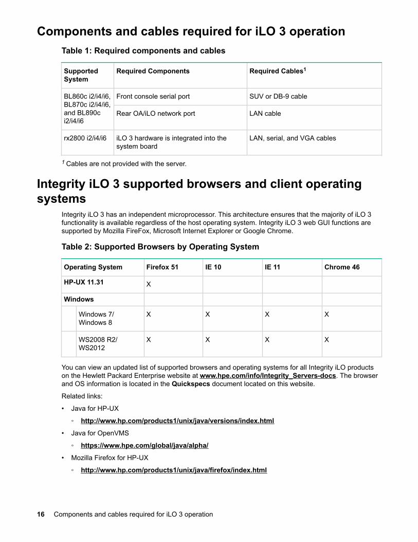
Components and cables required for iLO 3 operationTable 1: Required components and cables
SupportedSystem
Required Components Required Cables1
BL860c i2/i4/i6,BL870c i2/i4/i6,and BL890ci2/i4/i6
Front console serial port SUV or DB-9 cable
Rear OA/iLO network port LAN cable
rx2800 i2/i4/i6 iLO 3 hardware is integrated into thesystem board
LAN, serial, and VGA cables
1 Cables are not provided with the server.
Integrity iLO 3 supported browsers and client operatingsystems
Integrity iLO 3 has an independent microprocessor. This architecture ensures that the majority of iLO 3functionality is available regardless of the host operating system. Integrity iLO 3 web GUI functions aresupported by Mozilla FireFox, Microsoft Internet Explorer or Google Chrome.
Table 2: Supported Browsers by Operating System
Operating System Firefox 51 IE 10 IE 11 Chrome 46
HP-UX 11.31 X
Windows
Windows 7/Windows 8
X X X X
WS2008 R2/WS2012
X X X X
You can view an updated list of supported browsers and operating systems for all Integrity iLO productson the Hewlett Packard Enterprise website at www.hpe.com/info/Integrity_Servers-docs. The browserand OS information is located in the Quickspecs document located on this website.
Related links:
• Java for HP-UX
◦ http://www.hp.com/products1/unix/java/versions/index.html
• Java for OpenVMS
◦ https://www.hpe.com/global/java/alpha/
• Mozilla Firefox for HP-UX
◦ http://www.hp.com/products1/unix/java/firefox/index.html
16 Components and cables required for iLO 3 operation

NOTE:
1.5.0.00 needs patch
◦ https://h20392.www2.hpe.com/portal/swdepot/displayProductInfo.do?productNumber=HPUXFIREFOXPLUGINS
• Mozilla Firefox for Windows and Linux
◦ http://www.mozilla.com/firefox
• Browser Support for Java 1.6.0_31
◦ http://www.oracle.com/technetwork/java/javase/system-configurations-135212.html
SecurityYou must have strong security surrounding the iLO 3 device. HPE security requirements for iLO 3 includethe following:Authentication
Integrity iLO 3 incorporates authentication techniques with the use of Secure Socket Layer (SSL)encryption. It is password-based for web and password- and key-based for secure shell (SSH).
Authorization
Using local accounts, iLO 3 enables you to define up to 19 separate users and to vary the serveraccess rights of each user. The directory services capabilities of iLO 3 enables you to maintainnetwork user accounts and security policies in a central, scalable database that supports thousandsof users, devices, and management roles.
Integrity
Integrity iLO 3 incorporates a trusted Java applet for vMedia.
Privacy
Integrity iLO 3 uses SSL for web connections, RSL-RC4 encryption for serial console, AES128 forIRC, and AES256, AES128 or 3DES encryption algorithms for SSH connections. You can enable ordisable Telnet, web, and SSH connectivity.
NOTE:
Integrity iLO 3 ships with Telnet disabled by default.
Login
Integrity iLO 3 enforces a progressive login delay after failed login attempts have occurred (defaultthree) to protect the iLO from brute force dictionary attacks.
IMPORTANT:
Ensure that physical access to the server is limited. You can clear passwords by pressing the iLO 3Physical Presence button for longer than 8 seconds.
IMPORTANT:
For greater security, Hewlett Packard Enterprise recommends that iLO 3 management traffic be ona separate dedicated management network that is configured to allow only limited access fromselected secure systems by designated system administrators. This acts as the first line of defenseagainst security attacks. A separate network enables you to physically and logically control whichsystems are allowed to connect to the network and the iLO 3 LAN port.
Security 17

Ports, buttons, LEDs, and componentsThe iLO 3 functions are available through the server MP LAN port and the local port. On HPE Integrityserver blades, the iLO management LAN port is routed internally to the HPE BladeSystem OnboardAdministrator (OA) management LAN.
For locations and descriptions of iLO 3 LEDs, ports, and buttons on your server, see your user serviceguide or system specifications.
For more information on the Onboard Administrator for HPE server blades, see the c3000 or c7000Enclosure documentation and The BladeSystem Onboard Administrator documentation.
iLO 3 Physical Presence buttonThe iLO 3 Physical Presence button enables you to reset iLO 3 and reset the user-specific values tofactory default values. A momentary (4-8 seconds) press causes a soft reset of iLO 3 when the button isreleased.
NOTE:
There is no hard reset for iLO.
IMPORTANT:
Physical Presence buttons on all conjoined blades are functional. However, only the buttons onmonarch blades will enable TPM physical presence and iLO 3 security override modes, and events.Pressing this button on auxiliary blades will only cause a soft reset. A momentary press (less than 4seconds) on the monarch blade resets the entire group of iLOs for the nPartition.
The iLO 3 Physical Presence button has multiple functions, depending on the length of time it is pressed.It enables you to reset iLO, enter TPM physical presence mode, and enter security override mode.
NOTE:
When you use the Physical Presence button to perform an iLO 3 security override, it does notrequire powering off, removing a blade, or rebooting your OS.
• A momentary press of the button (less than 4 seconds) resets iLO and clears any security override orTPM physical presence mode that were initiated by this button.
NOTE:
The reset will fail if an iLO firmware upgrade is in process.
NOTE:
When you reset iLO, you lose LAN connections immediately.
• A 4-8 second press of the button places the system in physical presence mode for 15 minutes.
NOTE:
The physical presence mode will be cleared if, during the 15 minute period, you press thePhysical Presence button for 4 seconds or less.
18 Ports, buttons, LEDs, and components

NOTE:
The 15-minute timer will restart if, during the active physical presence mode period, you pressthe Physical Presence button for 4-8 seconds.
• An 8-12 second press of this button places iLO into security override mode for 15 minutes. Securityoverride mode enables you to enter iLO without being challenged for a password, enabling you to setup users.
NOTE:
The security override mode will be cleared if, during the 15 minute period, you press the PhysicalPresence button for 4 seconds or less.
NOTE:
The 15-minute timer will restart if, during the active security override mode period, you press thePhysical Presence button for 8-12 seconds.
NOTE:
iLO 3 does not log out any connected users when the 15-minute security override mode periodends.
• Pressing the Physical Presence button for more than 12 seconds has no effect on the system.• The UID LED blinks once after holding the Physical Presence button for 4 seconds, and once again
after holding the button for 8 seconds. This helps you gauge how long the button press has been held.
NOTE:
If the UID LED is blinking when the Physical Presence button is pressed, a firmware update is inprogress. During a firmware update, no iLO actions take place if the Physical Presence button ispressed.
• Blade systems without an OA account (or rack systems) are configured to permit creating or modifyinguser passwords while in the Security Override mode. Please refer Procedure 1: Creating ormodifying user passwords in Security Override mode.
NOTE:
Security override mode is not needed for blade systems accessed via an Onboard Administrator(OA) account. You can auto-login through the OA to iLO. Then you can use the iLO TUI's UCcommand (MP>CM>UC) or iLO GUI's Administration>User Administration>Local Accountspage to either create a user or modify the password of an existing user.
• Some special commands on the TPM require physical presence due to their sensitive nature. Pleaserefer Procedure 2: Using TPM Physical Presence mode for special commands.
• The Login Timeout in Minutes feature, shown in the iLO GUI screen below and in the text userinterface (see so command), disables logins after too many login failure attempts occur in a shorttimeframe. The login delay protects the iLO from brute force dictionary attacks. The iLO systemadministrator can configure the number of login failures allowed (default is 3). This option is in theTUI's so command or the GUI's Access Settings page (see below). Once the fault threshold has beenreached, the login process is delayed and an event is placed in the iLO Event Log (IEL). If the attackpersists, a critical event will also be placed in the System Event Log (SEL).
Ports, buttons, LEDs, and components 19

Figure 1: iLO 3 GUI Access Settings screen showing menu for TUI interface settings
Please refer Procedure 3: Canceling iLO Login Timeout via local Physical Presence button forcanceling the iLO login timeout.
Creating or modifying user passwords in Security Override mode
Procedure
1. Unplug the manageability LAN cable.
NOTE:
(For security reasons, this is the safest approach. Later, you will connect to iLO via the serialport.)
2. On the monarch blade, press the Physical Presence button for 8-12 seconds to place the system intoSecurity override mode.
TIP:
The UID LED will blink at 4 seconds, and again at 8 seconds. You can release the button afterthe second blink.
3. Login to iLO via the serial port with no user name or password.4. In iLO, perform the following steps:
a. Create a new user, or modify the password of an existing user.b. Re-enable security via the TUI or via the GUI.
5. Plug in the manageability LAN cable.
20 Creating or modifying user passwords in Security Override mode

TIP:
At the end of this procedure, you do not need to press the Physical Presence button on themonarch blade. This avoids the soft reset to iLO.
Using TPM Physical Presence mode for special commands
Prerequisites
On the monarch blade, press the Physical Presence button for 4-8 seconds to put the system in PhysicalPresence mode.
TIP:
The UID LED will blink at 4 seconds, and again at 8 seconds. You can release the button after thefirst blink.
Procedure
1. From a workstation on the network, or via the local serial connection, login to iLO, and bring up theconsole (MP>CO).
2. Perform the special TPM commands.3. To exit, wait the remainder of the 15 minutes for the TPM physical presence mode to expire.
NOTE:
Alternatively, you can exit immediately by pushing the Physical Presence button for less than 4seconds; however, this action will reset iLO.
Canceling iLO Login Timeout via local Physical Presence buttonThe system administrator with physical access to the server can bypass authentication and cancel anyprogressive Login Delay in progress by pressing the Physical Presence button on the monarch blade8-12 seconds to enter Security Override mode, or by pressing the Physical Presence button less than 4seconds to reset iLO.
TIP:
The UID LED will blink at 4 seconds, and again at 8 seconds. The first blink signals PhysicalPresence mode (release the button after the first blink), and the second signals Security Overridemode (release the button after the second blink.
When iLO is in Security Override mode, all authentication is suspended for 15 minutes, or until someoneexits Security Override mode by performing any of the following actions:
• Pressing the Physical Presence button less than 4 seconds• Manually exiting through the iLO TUI's SO command
• Manually exiting through the iLO GUI's Access Settings web page. The system administrator shouldexamine both the IEL and SEL to determine the cause of the login failures. (Login Delay must becancelled before you can login to iLO to view the IEL and SEL.)
HPE Integrity server blade componentsFor port locations and console connection procedures, see your server blade documentation. Also, forHPE server blades, see the c3000 or c7000 Enclosure documentation and The BladeSystem OnboardAdministrator documentation.
Using TPM Physical Presence mode for special commands 21

HPE BladeSystem Enclosures
c7000 EnclosureThe HPE BladeSystem c7000 Enclosure is an evolution of the entire rack-mounted infrastructure. Itconsolidates and repackages all the supporting infrastructure elements — compute, storage, network,and power into a single infrastructure-in-a-box that accelerates the integration and optimization of thedata center.
It is optimized for enterprise data center applications. It fits into standard size HPE and third-party racks;accommodates BladeSystem c-Class server blades, storage blades, and interconnect modules; andprovides all the power, cooling, and I/O infrastructure needed to support them.
For information on port locations and console connection procedures, see the HPE BladeSystem c7000Enclosure setup and installation guide on the Hewlett Packard Enterprise website at http://www.hpe.com/info/bladesystem/docs.
c3000 EnclosureThe HPE BladeSystem c3000 Enclosure is similar to the c7000. The Intelligent Management through theOnboard Administrator gives you complete control of your bladed infrastructure. For information on portlocations and console connection procedures, see the HPE BladeSystem c3000 Enclosure setup andinstallation guide on the Hewlett Packard Enterprise website at http://www.hpe.com/info/bladesystem/docs.
Onboard AdministratorThe BladeSystem Onboard Administrator (OA) for the HPE BladeSystem c7000 Enclosure is theenclosure MP, subsystem, and firmware base used to support the HPE Integrity server blades and all themanaged devices contained within the enclosure. Together with the enclosure HPE Insight Display, theOnboard Administrator has been designed for both local and remote administration of HPE BladeSystemc-Class.
This module and firmware provides:
• Wizards for simple, fast setup and configuration• Highly available and secure access to the HPE Bladesystem infrastructure• Security roles for server, network, and storage administrators• Automated power and cooling of the HPE Bladesystem infrastructure• Agent-less device health and status• Thermal Logic power and cooling information and control• email or Insight Display communications of problems within the enclosure
Each c7000 Enclosure is shipped with a first Onboard Administrator module/firmware. If needed, you canorder a second redundant Onboard Administrator module for each enclosure. When two OnboardAdministrator modules are present in a c7000 Enclosure, they work in an active - standby mode, assuringfull redundancy of the c7000 Enclosure integrated management.
Before setting up the HPE BladeSystem OA, Hewlett Packard Enterprise recommends that you read theHPE BladeSystem Onboard Administrator User Guide on the Hewlett Packard Enterprise website at c-Class Onboard Administrator.
Reading the guides ensures that you understand the HPE BladeSystem OA and that you properlycomplete the initial setup to facilitate its proper functioning.
Integrity rx2800 i2/i4/i6 serversFor complete information on the HPE Integrity rx2800 i2/i4/i6 server, such as server components, ports,LEDs, and specifications, see the HPE Integrity rx2800 i2 Server User Service Guide , HPE Integrity
22 HPE BladeSystem Enclosures

rx2800 i4 Server User Service Guide and HPE Integrity rx2800 i6 Server User Service Guide on theHewlett Packard Enterprise website at http://h17007.www1.hpe.com/us/en/enterprise/servers/solutions/info-library/index.aspx with the selection of the product as Integrity Servers and thesubcategory as Integrity rack servers.
Ports, buttons, LEDs, and components 23

Getting connected to iLO 3This chapter provides information on getting connected to iLO 3.
The ways you connect to iLO 3 will depend on whether you have a rackmount server or a server blade.
IMPORTANT:
For greater security, Hewlett Packard Enterprise recommends that iLO 3 management traffic be ona separate dedicated management network that is configured to allow only limited access fromselected secure systems by designated system administrators. This acts as the first line of defenseagainst security attacks. A separate network enables you to physically and logically control whichsystems are allowed to connect to the network and the iLO 3 LAN port.
Rackmount server connectionFor a rackmount server, you can connect directly through the serial console or you can connect using theMP LAN.
To set up the console:
Procedure
1. Determine the physical access method to connect cables. There are two physical connections to iLO3:a. Console serial port (RS-232)b. MP LAN port
2. Assign an IP address to the iLO 3 MP LAN using one of the following methods:a. DHCP and DDNS. Though there are several methods to configuring the LAN, Hewlett Packard
Enterprise recommends DHCP with DNS. DHCP with DNS comes preconfigured with defaultfactory settings, including a default user account and password. Use the DNS name on the iLONetwork Information Tag located on the front panel.
b. Console serial port (RS-232). Use this method to assign a static IP address instead of using DHCP.
Preparing to set up iLO 3Perform the following tasks before you configure the iLO 3 MP LAN:
• Determine the physical access method to select and connect cables.• Determine the iLO 3 MP LAN configuration method and assign an IP address if necessary.
Determining the physical iLO 3 access methodBefore you can access iLO 3, you must determine the correct physical connection method.
There are several ways you can physically connect to iLO 3. Table 3 lists the appropriate connectionmethod, required connection components, and connectors to the host console.
Use Table 3 to determine your physical connection method.
24 Getting connected to iLO 3

Table 3: Physical connection matrix
ConnectionMethod
Required Connection Components
Console serial port(RS-232)
• Host console• Console serial port (RS-232) DB-9F to DB-9F cable (modem eliminator cable)• Emulation terminal device (for example, a PC, laptop, or ASCII terminal)
These connection methods directly attach to the iLO 3 MP through the consoleserial port. This is an RS-232 connection from a workstation to the server's iLO 3MP console serial port. Serial cable concentrators are used to provide switchedaccess from one workstation to multiple servers. Typically, the console serial portmethod is used by an administrator in the data center.
LAN port 10/100 LAN cable
Remote access to the iLO 3 is a more convenient method. This remote access isthrough the MP LAN port. Depending on your LAN administration, this can berestricted to the datacenter, or extended outside the data center to your company'sintranet.
The iLO 3 has a separate LAN port from the system LAN port. It requires aseparate LAN drop, IP address, and networking information from that of theoperating system LAN port.
Determining the iLO 3 MP LAN configuration methodTo access iLO 3 through the MP LAN, iLO 3 must acquire an IP address. The way iLO 3 acquires an IPaddress is dependent upon whether DHCP is enabled or disabled on the server, and if DHCP and DNSservices are available to the server (see Table 4).
Once you have determined the iLO 3 access method, you must determine how you will configure the MPLAN in order to acquire an IP address using the following methods:
• DHCP/DNS through the management LAN (dynamically assigns an IP address): use the DNS nameon the iLO Network Information Tag located on the front panel.
• Setting up a static IP address using a laptop with DHCP services and the management LAN.• Local RS-232 serial port and a serial console (assigns a static IP address).
Table 4 provides all the possible IP address acquisition scenarios. Use this table to help you select theappropriate LAN configuration method to obtain an IP address.
Table 4: LAN configuration methods
DHCP DNS RS-232 Serial Port(iLO 3 MP LCcommand)
LAN Configuration Method
Yes Yes No DHCP
Yes Yes Yes DHCP or RS-232 serial port
No Yes Yes RS-232 serial port
Table Continued
Determining the iLO 3 MP LAN configuration method 25

DHCP DNS RS-232 Serial Port(iLO 3 MP LCcommand)
LAN Configuration Method
Yes No Yes RS-232 serial port
No No Yes RS-232 serial port
Yes No No Cannot set up the LAN; reconsider your criteria
Configuring the iLO 3 MP LAN using DHCP and DNSDHCP automatically configures all DHCP-enabled servers with IP addresses, subnet masks, and gatewayaddresses. All HPE Integrity entry class servers with iLO 3 are shipped from the factory with DHCPenabled.
Hewlett Packard Enterprise recommends using the DHCP and DNS method to simplify access to iLO 3.
When you use DHCP and DNS, you can connect to iLO 3 by entering the DNS name in your browserrather than an IP address only if the following applies:
• DHCP must be enabled (DHCP is enabled by default).• You are using a DHCP server that provides the domain name.• The primary DNS server accepts dynamic DNS (DDNS) updates.• The primary DNS server IP address was configured through the DHCP server.
IMPORTANT:
You must know the DNS domain name, which is served out by the DHCP server, unless its domainis local or the same domain.
To configure iLO 3 using DHCP and DNS:
Procedure
1. Obtain the factory-set DNS name from the iLO Network Information Tag located on the front panel.The DNS name is 14 characters long. It consists of the letters ilo followed by the 12 characters of theMAC address. For example:
ilo0014c39c064f2. This address is assigned to the iLO 3 MP system board. The system board has a unique MAC
address that identifies the hardware on the network.3. Connect the MP LAN cable from the server to an active network port.4. Apply AC power to the server.5. Open a browser, Telnet, or SSH client and enter the fully-qualified DNS name (the full path name
ending in the DNS name). The iLO 3 Log In window appears.6. Log in using the default user name and password.
CAUTION:
When DHCP is enabled, the system is vulnerable to security risks because anyone can access iLO3 until you change the default user name and password.
Hewlett Packard Enterprise strongly recommends you to assign user groups and rights beforeproceeding.
26 Configuring the iLO 3 MP LAN using DHCP and DNS
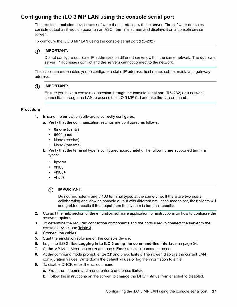
Configuring the iLO 3 MP LAN using the console serial portThe terminal emulation device runs software that interfaces with the server. The software emulatesconsole output as it would appear on an ASCII terminal screen and displays it on a console devicescreen.
To configure the iLO 3 MP LAN using the console serial port (RS-232):
IMPORTANT:
Do not configure duplicate IP addresses on different servers within the same network. The duplicateserver IP addresses conflict and the servers cannot connect to the network.
The LC command enables you to configure a static IP address, host name, subnet mask, and gatewayaddress.
IMPORTANT:
Ensure you have a console connection through the console serial port (RS-232) or a networkconnection through the LAN to access the iLO 3 MP CLI and use the LC command.
Procedure
1. Ensure the emulation software is correctly configured:a. Verify that the communication settings are configured as follows:
• 8/none (parity)• 9600 baud• None (receive)• None (transmit)
b. Verify that the terminal type is configured appropriately. The following are supported terminaltypes:
• hpterm• vt100• vt100+• vt-utf8
IMPORTANT:
Do not mix hpterm and vt100 terminal types at the same time. If there are two userscollaborating and viewing console output with different emulation modes set, their clients willsee garbled results if the output from the system is terminal specific.
2. Consult the help section of the emulation software application for instructions on how to configure thesoftware options.
3. To determine the required connection components and the ports used to connect the server to theconsole device, use Table 3.
4. Connect the cables.5. Start the emulation software on the console device.6. Log in to iLO 3. See Logging in to iLO 3 using the command-line interface on page 34.7. At the MP Main Menu, enter CM and press Enter to select command mode.8. At the command mode prompt, enter LS and press Enter. The screen displays the current LAN
configuration values. Write down the default values or log the information to a file.9. To disable DHCP, enter the LC command.
a. From the LC command menu, enter D and press Enter.b. Follow the instructions on the screen to change the DHCP status from enabled to disabled.
Configuring the iLO 3 MP LAN using the console serial port 27

10. Use the LC command to enter information for the IP address, host, subnet mask, gatewayparameters, and so on.
11. Enter XD -R -NC to reset iLO 3.12. After iLO 3 resets, log in to iLO 3 again and enter CM at the MP> prompt.13. To confirm that DHCP is disabled and display a list of updated LAN configuration settings, enter the
LS command.
NOTE:
HPE ProLiant servers allow you to assign a static IP address at boot time to iLO 3 using a VGAmonitor, keyboard, and mouse and HPE ProLiant BIOS commands. This feature is not available onHPE Integrity servers.
Server blade connectionYou do not have to physically connect to the iLO 3 via the SUV cable on a server blade. The iLO 3 onserver blades typically use the iLO/OA management connection on the blade enclosure, and areassigned LAN IP addresses by the OA.
Connecting the server blade to iLO 3 using the Onboard AdministratorIf the OA/iLO network port on the enclosure is connected to the local network that has a DHCP server,your iLO 3 MP IP address is automatically generated by the DHCP server. The server blade is factory setwith DHCP enabled.
To connect to iLO 3 using the OA, click the iLO link on the OA iLO GUI page:
Procedure
1. To connect to iLO 3 using the OA, navigate to the Device Bay Information page for the correspondingblade server from the navigation menu on OA GUI.
2. Click on the iLO link on Device Bay Information page and click the Web Administration link to launchiLO GUI in a separate browser window.
For HPE Integrity server blades, you can use the OA to manually set the IP addresses for all iLO 3s. Youcan also find the iLO 3 MP address so you can log in to iLO 3 directly.
For more information on using the Onboard administrator, see the following guides on the HewlettPackard Enterprise website at HPE BladeSystem c-Class Onboard Administrator:
• For CLI, see the HPE BladeSystem Onboard Administrator Command Line Interface User Guide.• For web GUI, see the HPE BladeSystem Onboard Administrator User Guide.
NOTE:
No user name/password authentication is required when iLO is accessed from the OA.
DHCP and auxiliary bladesAll blades have DHCP enabled by default. If you do not want an auxiliary blade to acquire one of the siteDHCP addresses, assign it an address through the OA, using Enclosure Bay IP Addressing (EBIPA).
To enable the OA to connect to the blade for its internal blade management, assign a local IP addressand matching gateway. For example, in a BL890c i2 server (four blades), use EBIPA to assign IPAddresses and Gateways of 192.168.2.x, where x is the Bay ID of each Auxiliary Blade. This is just anexample; other similar IP addresses (192.168.x.x) also work. EBIPA requires each assigned IP address tobe unique.
28 Server blade connection

IMPORTANT:
Invalid IP addresses will disable the ability for the OA to do Single Sign On (SSO) to the AUXblade(s). Alternatively, assigning a valid IP address and Gateway such as 192.168.2.x (local only tothe enclosure) will enable the OA for minor blade management without requiring network DHCPaddresses.
For more information on assigning IP addresses on auxiliary blades, see the HPE BladeSystem OnboardAdministrator User Guide on the Hewlett Packard Enterprise website at HPE BladeSystem c-ClassOnboard Administrator.
Auto loginAuto login provides direct access to iLO 3 from the OA for users who already logged in to the OA. A userwho has authenticated the connection to the OA can follow a link to a server blade in the enclosurewithout an additional login step. Auto login features and usage are as follows:
• A user who has authenticated a connection to the OA is able to establish a connection with iLO 3without providing the user login and password to iLO 3.
• The OA provides the following auto login connection methods to iLO 3 links to users to launch theseconnections to iLO 3:
iLO CLI SSH connection
If you logged in to the OA CLI through SSH, enter connect server <bay number> toestablish an SSH connection with iLO 3.
iLO web GUI connection
If you logged in to the OA web GUI, click the link to launch the iLO web GUI.• Auto login is implemented using IPMI over Ethernet between the OA and iLO 3 to create and delete
user commands.• Supports a maximum of four simultaneous OA user accounts. The OA keeps track of these users
locally. The information maintained for each user is the user name, password, and privilege levels.• User accounts for the auto login feature are created in the MP database when an auto login session is
established. These accounts are deleted when the auto login session is terminated.• If a maximum number of user accounts has already been reached, and the OA creates another
account on iLO 3. The OA sends a request to iLO 3 to delete one of the previously created accounts,before attempting to create a new one.
• If iLO 3 is rebooted or power-cycled, it verifies any previously created OA user accounts in the iLO 3user database when it boots up. If there are any previously-created OA user accounts, it deletes thoseaccounts.
• View and manage user accounts created in iLO 3 by the OA like any other local user account on iLO3. To view and manage user accounts, use the TUI WHO, UC commands; or use the UserAdministration page in the web GUI.
• View and disconnect user connections established through the auto login feature just like otherconnections to iLO 3. To view and disconnect user connections, use the TUI WHO, DI commands, oruse the User Administration pages in the web GUI.
• The OA supports three types of users: administrators, operators, and users. These user types map tothe following iLO 3 capabilities:
Administrators
Can perform any function including iLO 3 MP configuration. This level equates to an iLO 3 userwith all privilege levels such as, Administer User Accounts, Remote Console Access, VirtualPower and Reset, Virtual Media, and Configure iLO MP settings. It enables access to all aspectsof the OA including configuration, firmware updates, user management, and resetting defaultsettings.
Auto login 29

Operators
Provided access to the serial console and vMedia. This level equates to an iLO 3 user withRemote Console Access, Virtual Power and Reset, Virtual Media, and Configure iLO settings. Itallows access to all but configuration changes and user management. This account is used forindividuals who might be required to periodically change configuration settings.
Users
Provided read-only login access to iLO 3. This account is used for individuals who need to see theconfiguration of the OA but do not need the ability to change settings. This level equates to an iLO3 user with no privileges set.
NOTE:
For information on how to set user roles and privilege levels in the OA, see the HPEBladeSystem Onboard Administrator User Guide on the Hewlett Packard Enterprise website at HPE BladeSystem c-Class Onboard Administrator.
Initiating an auto login session1. The OA finds the first available auto login user by finding the first user entry with a time-created value
of 0. (OAtmp1...OAtmp5).2. If there are no available users, the oldest user is deleted.
NOTE:
This might terminate a currently active session.
The OA sends a request to iLO 3 to delete that user.3. The OA sends a command to create an OA user.4. The OA launches an SSH or web GUI connection to iLO 3 and logs in with the created user’s
credentials.
Terminating an auto login sessionWhen the auto login CLI or web GUI session is terminated, the temporary Auto Login iLO 3 account isdeleted.
User account cleanup during IPF blade initializationThe OA and iLO 3 perform the following during an IPF blade initialization:
• When a server blade is inserted, or iLO 3 or the OA is reboot or reset, both the OA and iLO performcleanup of the accounts that might have been created for auto login before the reset.
• When iLO 3 initializes, the OA marks all four user slots as unused.• Integrity iLO 3 scans its local user accounts. If there are any OA-created user accounts, they are
deleted from the iLO 3 user database.
Auto login troubleshootingThere might be times when auto login fails. The following information provides possible reasons for thefailure:
User creation
When the OA sends a request to iLO 3 to create a new user, iLO 3 attempts to create a user in the localiLO 3 user database. Creation of an OA user might fail for a number of reasons:
• The local user database is disabled in iLO 3 and LDAP authentication is being used.• The iLO 3 user database has reached the maximum number of users (19 users).
User login
30 Getting connected to iLO 3

After an OA user has been created in the iLO 3 database, the OA user login can still fail for a number ofreasons:
• Maximum number of connections for the requested connection type (SSH, Telnet, web GUI) to iLO 3has been reached.
• Requested connection type (SSH, Telnet, or web) to iLO 3 is currently disabled.
User deletion
When the OA sends a request to iLO 3 to delete a user, iLO 3 attempts to delete that user from the localiLO 3 user database.
Deletion of an OA user might fail when a user with the specified login does not exist (user might havebeen deleted through other iLO 3 user interface).
Connecting to a server blade iLO 3 using the console serial portWhen a physical connection directly to a server blade iLO 3 is necessary, you can connect through theconsole serial port.
For a server blade, you can connect directly through the SUV cable to the serial console or you canconnect using the MP LAN internal connection in the blade enclosure. You do not cable up a separate MPLAN cable to each server blade.
To log in to iLO 3, see Logging in to iLO 3 on page 34.
Connecting to iLO 3 using the Onboard AdministratorFor instructions on physically connecting a server blade to iLO 3 through the OA, see the HPEBladeSystem c7000 Enclosure setup and installation guide on the Hewlett Packard Enterprise website at http://www.hpe.com/info/bladesystem/docs.
Unless SSH is disabled and the local user database is disabled (enabled is default), you can connectfrom the OA using connect server n.
On HPE Integrity server blades, you also have access to the console port.
It is not necessary to physically connect to iLO 3 through the console serial port to perform managementtasks. Use the OA/iLO LAN port to communicate with any iLO 3 in the enclosure and the OA. You can usethe LCD panel and the OA to configure and determine the iLO MP LAN address.
To log in to iLO 3, see Logging in to iLO 3 on page 34.
Additional setupThis section provides additional information to set up iLO 3.
Integrity iLO 3 comes preconfigured with an Administrator account and a randomly generated password.
All Rights (Administrator) level user:
login = Administratorpassword = Randomly generated password found on the iLO Network Information Tag
NOTE:
• On server blades, the iLO Network Information Tag is located on the right side of the monarchblade.
• On HPE Integrity rx2800 i2/i4/i6 servers, the iLO 3 Network Information Tag is located on a pull-tab on the front panel.
Connecting to a server blade iLO 3 using the console serial port 31

Modifying default account configuration settingsLog in as the Administrator.
Changing the default password
Procedure
1. Access the MP Main Menu.2. At the hpiLO-> prompt, enter CM.3. At the CM:hpiLO-> prompt, enter UC and follow the prompts.
Setting up user accounts
Procedure
1. Access the MP Main Menu.2. At the hpiLO-> prompt, enter CM.3. At the CM:hpiLO-> prompt, enter UC and follow the prompts to modify user accounts.
Setting up securityFor greater security, Hewlett Packard Enterprise recommends that only administrators be granted accessto modify user account information.
Setting security accessDetermine the security access required and what user accounts and privileges are needed. Integrity iLO 3provides options to control user access. To prevent unauthorized access to iLO 3, select one of thefollowing options:
• Create local accounts. You can store up to 19 user names and passwords to manage iLO 3 access.This is ideal for small environments such as labs and small-to-medium sized businesses.
• Use corporate directory services to manage iLO 3 user access. This is ideal for environments with alarge number of frequently changing users. If you plan to use directory services, Hewlett PackardEnterprise recommends leaving at least one local account enabled as an alternate method of access.
For more information on how to create local accounts and use directory services, see Installing andconfiguring directory services on page 135.
Setting iLO MP LAN from UEFIIntegrity iLO 3 supports the UEFI utility to view the iLO LAN parameters.
To view the iLO LAN parameters from UEFI:
Procedure
1. Boot to the UEFI Front Page. See Accessing UEFI or the OS from iLO 3 on page 46.
NOTE:
You will only be able to boot to UEFI if the operating system has not yet been booted.
2. To launch the iLO Setup Tool, press F8 or press I.3. For a list of options, enter help. The screen displays the options.4. Enter L. The current iLO LAN configuration appears.
32 Modifying default account configuration settings

Current iLO LAN configuration: IP Address : 15.255.99.57 Gateway : 15.25.96.1 Subnet : 255.255.248.0
NOTE:
You are viewing the iLO LAN parameters that have already been configured. To modify the LANparameters, connect to iLO or the OA for server blades.
5. To exit, enter Q.
If the iLO LAN configuration has not been initialized, this setup tool enables you to set a static IPconfiguration.
IMPORTANT:
For all Integrity BL8x0c versions, the recommendation is NOT to use this tool to set the iLO IPaddresses because it uses a static IP and will cause iLO to not respond to EBIPA, which is thepreferred method for setting iLO addresses in a blades environment. This tool is primarily used forthe Integrity rx2800 i2/i4/i6 servers—which lack OA/EBIPA tools. Future updates may not allowusers to use the iLO Setup Tool to set the iLO LAN configuration on Integrity BL8x0c versions.
Getting connected to iLO 3 33

Logging in to iLO 3This chapter provides instructions on how to log in to iLO 3.
Logging in to iLO 3 using the web GUIProcedure
1. Obtain the iLO Network Information Tag. The default iLO 3 user name and password is on this tag.
NOTE:
• On server blades, the iLO Network Information Tag is located on the right side of the monarchblade.
• On HPE Integrity rx2800 i2/i4/i6 servers, the iLO 3 Network Information Tag is located on apull-tab on the front panel.
2. Open a web browser, and then enter the DNS name or the IP address for the iLO 3.3. Log in using the default iLO 3 user name and password.
Logging in to iLO 3 using the command-line interfaceProcedure
1. Obtain the iLO Network Information Tag. The default iLO 3 user name and password is on this tag.
NOTE:
• On server blades, the iLO Network Information Tag is located on the right side of the monarchblade.
• On HPE Integrity rx2800 i2/i4/i6 servers, the iLO 3 Network Information Tag is located on apull-tab on the front panel.
2. Access iLO 3 through the LAN, using Telnet, SSH, or a console emulation method. The iLO 3 MP loginprompt appears.
3. Log in using the default the iLO 3 user name and password.
The following is the MP Main Menu:
CO: Console VFP: Virtual Front Panel CM: Command Menu CL: Console Logs SL: Show Event Logs HE: Main Help Menu X: Exit ConnectionFor information on the iLO 3 MP menus and commands, see Text user interface on page 45.
TIP:
When logging in to iLO 3, using the local or remote console serial ports, the login prompt might notappear if another user is logged in through these ports. In this event, use Ctrl-B to access the MPMain Menu and the hpiLO-> prompt.
34 Logging in to iLO 3

IMPORTANT:
On HPE Integrity server blades, user interfaces such as MP TUI and console on the auxiliary bladescannot be used for system control. They are enabled for HPE Support. You must enter all system-level commands only on the monarch blade.
Logging in to iLO 3 through the OAOn systems that use the OA, you can log in to the web GUI or the TUI through the OA.
To log in to the OA web GUI, click the iLO link from the OA.
To log in to the OA TUI:
Procedure
1. To see a list of what is in each bay, use show server info from the OA TUI.2. To log in to that bay, use connect server n.
You do not need a username/account; but you do need an empty SSH connect slot. SSH needs to beenabled and there cannot be too many other SSH connections already in use.
Logging in to iLO 3 through the OA 35

Accessing the host (operating system) consoleThis chapter describes several ways to access the host console of an HPE Integrity server blade.
Accessing a text host console through iLO 3 virtual serialconsole
To interact with iLO 3 through the web:
Prerequisites
Web browser access is an embedded feature of iLO 3.
Before starting this procedure, you must have the following information:
• DNS name for the iLO MP LAN• Host name
Procedure
1. Open a web browser and enter the DNS name or the IP address for the iLO 3 MP.2. Log in using your user account name and password at the login page. (Figure 2).
Figure 2: Web Login page
NOTE:
The iLO web GUI session times out after the configured idle connection timeout period if there isno activity; but it will not time out if the Remote Serial Console or the Integrated Remote Consoleis launched, or if Virtual Media is connected.
3. Click Sign In. The Status Summary page (Figure 3) appears after login.
36 Accessing the host (operating system) console

Figure 3: Status Summary page4. Select the web interface functions by clicking the tabs at the top of the page. Each function lists
options in the Navigation Control on the left side of the page.
Accessing online helpThe iLO 3 web interface has a robust help system. To launch iLO 3 help and display help about that page,click the help ? at the top right corner of each page.
Accessing a text host console using the TUIProcedure
1. Log in using your user account name and password at the login page.2. To switch the console terminal from the MP Main Menu to mirrored/redirected console mode, enter the
CO command at the hpiLO-> login prompt. All mirrored data appears.3. To return to the iLO 3 MP command interface, enter Ctrl-B or Esc (.
Help systemIntegrity iLO 3 has a robust help system. To access the Help menu from the TUI, enter HE at the hpiLO-> prompt. The following is the MP Help Main Menu:
==== MP Help: Main Menu ===============================================
Integrated Lights-Out for HPE Integrity - Management Processor (MP)
MP Help SystemEnter a command at the help prompt:
OVerview : Launch the help overview LIst : Show the list of MP Main Menu commands <COMMAND> : Enter the command name for help on individual command TOPics : Show all MP Help topics and commands HElp : Display this screen Q : Quit help====hpiLO->:HE
Accessing online help 37

To display the Main Menu Command List, enter LI at the HE:hpiLO-> prompt.
To return to the MP Main Menu, enter Q.
To access help from the web GUI, click Help. You can also click the ? at the top right corner of each pageto display help about that page.
38 Accessing the host (operating system) console

Configuring DHCP, DNS, LDAP, and schema-free LDAP
This chapter provides information on how to configure DHCP, DNS, LDAP extended schema, andschema-free LDAP.
Configuring DHCPDHCP enables you to automatically assign reusable IP addresses to DHCP clients. This section providesinformation on how to configure DHCP options.
This iLO 3 MP host name will appear at the iLO 3 MP command mode prompt. Its primary purpose is toidentify the iLO MP LAN interface in a DNS database.
NOTE:
The HP-UX system name displayed by the uname -a command is different than the iLO 3 MP hostname.
If the IP address, gateway IP address, and subnet mask are obtained through DHCP, you cannot changethem without first disabling DHCP. If you change the host name and the IP address was obtained throughDHCP and registered with dynamic DNS (DDNS), a “delete old name” request for the old host name andan “add name request” for the new host name are sent to the DDNS server.
If you change the DHCP status between enabled and disabled, the IP address, subnet mask, andgateway IP address are set to default values (0.0.0.0). Also, the DNS parameters are voided. When youchange the DHCP status from enabled to disabled, the DNS parameters for using DHCP are set todisabled, and the Register with DDNS parameter is set to No. When you change the DHCP statusfrom disabled to enabled, the DNS parameters for using DHCP are set to enabled, and the Registerwith DDNS parameter is set to Yes.
NOTE:
DNS is the comprehensive RFC standard; DDNS provides only a part of the DNS standardfunctionality.
Use the LC command to perform the following actions to configure DHCP:
NOTE:
The LC command sets the next boot LAN settings. It does not display the current settings. Todisplay the current settings, you must use the LS command. When you change settings using theLC command, the settings do not take effect until the next boot of the iLO.
• Set all default LAN settings.
[hostname] CM:hpiLO-> LC -all DEFAULT –nc• Display next LAN settings.
[hostname] CM:hpiLO-> LC -nc• Modify the MP DHCP status.
[hostname] CM:hpiLO-> LC -dhcp disabled• Modify the MP IP address.
[hostname] CM:hpiLO-> LC -ip 192.0.2.1
Configuring DHCP, DNS, LDAP, and schema-free LDAP 39

• Modify the MP host name.
[hostname] CM:hpiLO-> LC -h hostname• Modify the MP subnet mask.
[hostname] CM:hpiLO-> LC -s 255.255.255.0• Modify the MP gateway address.
[hostname] CM:hpiLO-> LC -g 192.0.2.1• Set the link state to auto negotiate.
[hostname] CM:hpiLO-> LC -link auto• Set the link state to 10 BaseT.
[hostname] CM:hpiLO-> LC -link x(Other option is -link c (100BaseT))
• Set the remote console serial port address.
[hostname] CM:hpiLO-> LC -rsc n• Set the SSH console port address.
[hostname] CM:hpiLO-> LC -ssh 22
Configuring DNSTo use the DNS command to display and modify the DNS configuration:
Procedure
1. From the MP Main Menu, enter command mode.2. At the CM:hpiLO-> prompt, enter DNS. The screen appears current DNS data.3. To select all parameters, enter A when prompted. The screen displays the current DHCP for DNS
server status.4. When prompted, enter Enabled or Disabled. The screen displays the current DHCP for DNS
domain name status.5. When prompted, enter Enabled or Disabled. The screen displays the current register with DDNS
server value.6. When prompted, enter Yes or No. The screen displays the current DNS domain name.7. When prompted, enter a new value. The screen displays the primary DNS server IP address.8. When prompted, enter a new value. The screen displays the optional secondary DNS server IP
address.9. When prompted, enter a new value. The screen displays the optional tertiary DNS server IP address.10. When prompted, enter a new value.
The DNS configuration is updated as follows:
New DNS Configuration (* modified values):
* S - DHCP for DNS Servers : Disabled * D - DHCP for DNS Domain Name : Disabled R - Register with DDNS Server : Yes * N - DNS Domain Name : mpdns.company.com * 1 - Primary DNS Server IP : 192.0.2.1 2 - Secondary DNS Server IP : Enter parameter(s) to revise, Y to confirm, or [Q] to Quit: Y
-> DNS Configuration has been updated
40 Configuring DNS
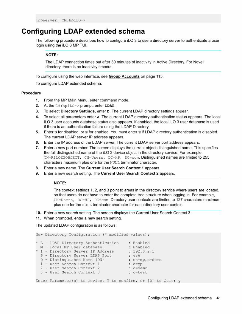
[mpserver] CM:hpiLO->
Configuring LDAP extended schemaThe following procedure describes how to configure iLO 3 to use a directory server to authenticate a userlogin using the iLO 3 MP TUI.
NOTE:
The LDAP connection times out after 30 minutes of inactivity in Active Directory. For Novelldirectory, there is no inactivity timeout.
To configure using the web interface, see Group Accounts on page 115.
To configure LDAP extended schema:
Procedure
1. From the MP Main Menu, enter command mode.2. At the CM:hpiLO-> prompt, enter LDAP.3. To select Directory Settings, enter D. The current LDAP directory settings appear.4. To select all parameters enter A. The current LDAP directory authentication status appears. The local
iLO 3 user accounts database status also appears. If enabled, the local iLO 3 user database is usedif there is an authentication failure using the LDAP Directory.
5. Enter D for disabled, or E for enabled. You must enter E if LDAP directory authentication is disabled.The current LDAP server IP address appears.
6. Enter the IP address of the LDAP server. The current LDAP server port address appears.7. Enter a new port number. The screen displays the current object distinguished name. This specifies
the full distinguished name of the iLO 3 device object in the directory service. For example,CN=RILOE2OBJECT, CN=Users, DC=HP, DC=com. Distinguished names are limited to 255characters maximum plus one for the NULL terminator character.
8. Enter a new name. The Current User Search Context 1 appears.9. Enter a new search setting. The Current User Search Context 2 appears.
NOTE:
The context settings 1, 2, and 3 point to areas in the directory service where users are located,so that users do not have to enter the complete tree structure when logging in. For example,CN=Users, DC=HP, DC=com. Directory user contexts are limited to 127 characters maximumplus one for the NULL terminator character for each directory user context.
10. Enter a new search setting. The screen displays the Current User Search Context 3.11. When prompted, enter a new search setting.
The updated LDAP configuration is as follows:
New Directory Configuration (* modified values):
* L - LDAP Directory Authentication : Enabled M - Local MP User database : Enabled* I - Directory Server IP Address : 192.0.2.1 P - Directory Server LDAP Port : 636 D - Distinguished Name (DN) : cn=mp,o=demo 1 - User Search Context 1 : o=mp 2 - User Search Context 2 : o=demo 3 - User Search Context 3 : o=test
Enter Parameter(s) to revise, Y to confirm, or [Q] to Quit: y
Configuring LDAP extended schema 41

-> LDAP Configuration has been updated
Login process using directory services with extended LDAPYou can choose to enable directory services to authenticate users and authorize user privileges forgroups of iLO 3s. The iLO 3 directory services feature uses the industry-standard LDAP. HPE layersLDAP on top of SSL to transmit the directory services information securely to the directory servers.
Hewlett Packard Enterprise provides tools to extend directory schema and install snap-ins for MicrosoftActive Directory and Novell e-directory. Please refer to Chapter 8, “Installing and configuring directoryservices” for more information on installation and configuration of directory services.
When LDAP is enabled with extended schema in iLO 3, after users enter their login and password, thebrowser sends the cookie to iLO 3. The iLO 3 processor accesses the directory service to determinewhich roles are available for that user login. The iLO 3 first uses the credentials to access the iLO 3device object in the directory. The directory service returns only the roles for which the user has rights. Ifthe user credentials allow read access to the iLO 3 device object and the role object, iLO 3 determinesthe role object distinguished name and the associated user privileges. The iLO 3 then calculates thecurrent user privileges based on those roles and grants them to that user.
Configuring schema-free LDAPIMPORTANT:
Due to command syntax changes in schema-free LDAP, some customer-developed scripts may notrun. You must change any scripts you developed to enable them to run with the new schema-freeLDAP syntax.
Integrity iLO 3 schema-free directory integration enables you to use the standard directory schemainstead of adding HPE schema to the directory database. You accomplish this by authenticating usersfrom the directory database and authorizing iLO 3 privileges based on matching groups stored on eachiLO 3.
In addition to general directory integration benefits, iLO 3 schema-free integration provides the followingadvantages:
• Easy implementation without schema extensions.
iLO 3 schema-free integration is configured from any iLO 3 user interface (browser, command line, orscript).
• Minimal administration and maintenance.
◦ After initial setup, only groups and permissions require maintenance support on iLO 3; typicallygroup and permission changes occur infrequently.
◦ The schema-free approach does not require updating directory databases with new iLO 3 devicesobjects.
• Reliable security.
Integrity iLO 3 schema-free integration does not affect standard directory attributes, avoidingconflicting use of attributes that can result over time.
NOTE:
If you have already extended your directory with HPE schema, there is no need to switch to theschema-free approach. Schema extension provides the lowest maintenance approach for directoryintegration. When this process has taken place, there is no advantage for the schema-freeapproach until a schema change is required.
To configure schema-free LDAP:
42 Login process using directory services with extended LDAP

1. Follow the procedure for Configuring LDAP extended schema on page 41, but omit Step 8. It is notnecessary to enter a new port number.
2. Set up directory security groups.
Setting up directory security groupsThe following procedure describes how to set up directory security groups in schema-free LDAP using theiLO 3 MP TUI. To use the web interface, see Group Accounts on page 115.
NOTE:
Due to command syntax changes in schema-free LDAP, some customer-developed scripts may notrun. You must change any scripts you developed to enable them to run with the new schema-freeLDAP syntax.
NOTE:
You must select the default schema from the LDAP command for the schema-free LDAP settings towork.
To set up directory security groups:
Procedure
1. At the CM:hpiLO-> prompt, enter LDAP. The screen displays the current LDAP options.
[hqgstlb3] CM:hpiLO-> ldap
LDAP
Current LDAP options: D - Directory settings G - Security Group Administration
2. Enter G. The current group configuration appears.
Enter menu item or [Q] to Quit:G
Current Group Configuration:
Group Names Group Distinguished Names Access Rights
--------------------------------------------------------------------------
1 - Administrator C, P, M, U 2 - User C, P 3 - Custom1 None 4 - Custom2 None 5 - Custom3 None 6 - Custom4 None
Only the first 30 characters of the Group Distinguished Names are displayed.
Enter number to view or modify, or [Q] to Quit:3. Enter the number for the group you want to view or modify. The current LDAP group settings appear.4. Set up a group distinguished name.5. Select rights for the group.6. Enter Y to confirm.
Setting up directory security groups 43

Login process using directory services without schema extensionsYou can control access to iLO 3 using directories without schema extensions. Integrity iLO 3 acquires theuser name to determine group membership from the directory. The iLO 3 then cross-references the groupnames with its locally stored names to determine user privilege level. Integrity iLO 3 must be configuredwith the appropriate group names and their associated privileges. To configure iLO 3, use one of thefollowing methods:
• Web GUI (Administration > Directory Settings > Group Administration page)• iLO 3 MP TUI (LDAP command)
44 Login process using directory services without schema extensions

Using iLO 3There are several options for using iLO 3. This chapter provides information and instructions on eachavailable option.
Text user interfaceThis section provides information on the text user interface (TUI) commands you can run in iLO 3.
NOTE:
HPE Integrity server blades do not have fans or power supplies. Therefore, the response to certaincommands are different than a rackmount server.
MP command interfacesTable 5: MP command interfaces
MP CommandInterface
Description
MP Main Menu The MP Main Menu appears when you first access the iLO 3 MP. The MP MainMenu supports the basic MP commands for server control and the iLO 3 MPconfiguration.
Command Menu The Command menu provides a set of commands that help monitor andmanage the server. It switches the console terminal from the MP Main Menu tocommand interface mode. To access the Command menu, enter CM at the MPMain Menu and enter HE LI at the [hostname] CM:hpiLO-> prompt.
MP main menuAfter logging in to the iLO 3 MP, the MP Main Menu appears. The MP Main Menu runs as a privatesession. Other iLO 3 users do not see the actions you perform in the private session.
Integrity iLO 3 can support multiple sessions to perform independent tasks:
• Multiple windows logged into iLO 3 to monitor VFP or study event logs in one window whileadministering the server from another window.
• Resetting a server from one window and monitoring the boot from another window while interactingwith the console from a third window.
Table 6 lists the MP Main Menu commands.
Table 6: MP Main Menu commands
Command Description
CO Selects console mode
VFP Displays the virtual front panel
Table Continued
Using iLO 3 45

Command Description
CM Enters command interface mode
CL Views the console log
SL Shows event logs
HE Displays help for the menu or command
X Exits
TIP:
An effective method for using iLO 3 is to log in more than once with different views for each session.For instance, one window logged in viewing the console, and another viewing the virtual front panel.
MP Main Menu commandsThe following sections describe the MP Main Menu commands.
CO (Console): Leave the MP Main Menu and enter console modeCO switches the console terminal from the MP Main Menu to mirrored/redirected console mode. Allconsole output is mirrored to all users in console mode. Only one of the mirrored users at a time has writeaccess to the console. To get console write access, press Ctrl-Ecf.
To return to the MP Main Menu, press either Ctrl-B or Esc and (. Verify that all mirrored consoles are ofthe same terminal type for proper operation.
To run an ASCII screen-oriented application (SAM) or a file transfer program (ftp), the console is not therecommended connection. Hewlett Packard Enterprise recommends using the LAN and connectingdirectly with Telnet or the web to the system over the system LAN.
Accessing UEFI or the OS from iLO 3The UEFI is an Itanium-based architecture feature that provides an interface between the server bladeOS and the server blade firmware. UEFI provides a standard environment for booting an OS and runningpreboot applications.
To access UEFI or the OS from iLO 3:
Procedure
1. From the MP Main Menu, enter CO to access the Console Menu. Depending on how the server bladewas configured from the factory, and if the OS is installed at the time of purchase, you should be inone of two places:a. EFI Boot Manager menub. OS login prompt
2. If the server blade has a factory-installed OS, you can interrupt the boot process to configure yourspecific EFI parameters.
VFP (Virtual Front Panel): Simulate the display panelVFP simulates the display panel on the front of the server. It gives real-time feedback on the results ofsystem events and user actions. VFP works by decoding system events. It provides a live display of majorstates of the system, the latest system activity, and the state of front panel LEDs.
46 MP Main Menu commands

IMPORTANT:
Integrity iLO 3 has no LED that equates to the Blade Health LED located on the front panel of eachindividual BL8x0c i2/i4/i6 server blade. The Blade Health LED represents the health of the individualserver blade. The virtual LEDs in the iLO GUI and TUI reflect system and partition health. Theclosest equivalency to the Blade Health LED is a field called Bay [x] Health on the System Healthpage of the iLO GUI.
The VFP is a representation of the system and partition state and the system status in the boot process(running non-OS code, and more).
The following virtual LEDs are located in the VFP:
• Health• System• Locator• Power
VFP shows forward progress during boot by indicating how many events have been received since theboot started and whether there have been any errors (events with alert level 3 or greater) since the lastboot. To clear the yellow attention indicator on the front of the system, use the SL command and accessthe System Event Log (SEL).
Each user viewing VFP is in private session mode.
See also: LOC (locator LED), and SL (show logs).
CM (Command Mode): Enter command modeCM switches the console terminal from the MP Main Menu to mirrored command interface mode. TheCommand menu provides you with a set of standard command-line interface commands that help monitorand manage the server.
To display the list of MP command mode commands:
Procedure
1. From the MP Main Menu, enter CM .2. Enter HE LI at the CM: hpiLO-> prompt.
To return to the MP Main Menu, press Ctrl-B.
CL Display console historyCommand access level: Remote Console access for viewing the log. Configure MP Settings access forclearing the log.
The CL command displays up to 256KB of logged console data (or about 250 pages of output) sent fromthe system to the console path and stored for later analysis.
Console data is stored in a buffer in nonvolatile memory. By default, data is displayed from the beginningof the buffer to the end of the buffer. You can control the starting point from which the data displays andnavigate through the data.
An image of the console history appears when you enter the CL command. Console output continues tobe logged while this buffer is read, and nothing is lost in the meantime.
The CL command does not support command line usage or scripting.
See Also: SL, VT
Using iLO 3 47

SL (Show Logs): Display the status logsSL displays the contents of the status logs, System Event Log (SEL), Forward Progress Log (FPL), andiLO Log. You can also run the status in live mode presenting each event as it is received.
NOTE:
After entering the SL command, any subcommand you enter (such as SE log selection, SL menuoptions) does not require entering <CR>. The only exception to this is when a log entry number isrequested. You must enter <CR> after entering a log number.
Events communicate system information from the source of the event to other parts of the system, then tothe system administrator. Events are produced by intelligent hardware modules, the operating system,and system firmware. Events funnel into iLO 3 from different sources throughout the server. The iLO 3stores new events in nonvolatile memory.
The SL command also displays the contents of the iLO 3 Event Log. The following events are recorded:
• iLO 3 MP login and logout attempts• Command logging for specific commands• All entries in the existing history log with more detail
Each time a user logs in or out of iLO 3, an event is logged. In the event of a login failure, an event islogged if the number of continuous login failure attempts equals the password fault value.
The following example shows the event log viewer menu:
Event Log Viewer Menu:
Log Name Entries % Full Latest Timestamped Entry------------------------------------------------------------------------------- E - System Event 51 2 % 27 Mar 2010 02:22:38 F - Forward Progress 1556 7 % I - iLO Event 12 2 % 27 Mar 2010 02:33:26 C - Clear SEL and FPL L - Live Events
Enter menu item or [Ctrl-B] to Quit:The following example shows the display in the SL menu E system event submenu:
# Location |Alert | Encoded Field | Data Field | Keyword/Timestamp-------------------------------------------------------------------------------10 SFW 3,1,0,0 2 5488006341E10011 0000000000000000 BOOT_START 27 Mar 2010 20:07:519 SFW 4,0,0,0 2 548C006301E1000F 0000000000000000 BOOT_START 27 Mar 2010 20:07:51
SL:hpiLO (+,-,<CR?,D,F,L,J,H,K,T,A,U,?,Q or Ctrl-B to Quit)->t SL:hpiLO (+,-,<CR?,D,F,L,J,H,K,T,A,U,?,Q or Ctrl-B to Quit)->j
Jump to entry number: 10
Log Entry 10: 27 Mar 2010 20:07:51Alert Level 2: InformationalKeyword: BOOT_STARTCPU starting boot
48 Using iLO 3

Logged by: System Firmware located in bay 3,socket 1,cpu 0,thread 0Data: Major change in system state - Boot Start5488006341E10011 0000000000000000
In this example: the “Alert” has a “*” because all alerts >= 3 have a “*”.
# Location |Alert | Encoded Field | Data Field | Keyword/Timestamp-------------------------------------------------------------------------------69 ILO 3 *3 608022E620E10086 0000000000000000 ILO_SPECIAL_MODE 01 Jan 2001 12:32:51• “#” is the entry number. Use this with the “j” menu comment to a particular log (if you don’t want to
scroll to it).• Location: 3,1,0,0 means blade 3, socket 1, cpu 0, thread 0.• To find out more about these events, use T to switch to text mode.
Command logging is run for the following commands: CA, DC, DI, DNS, FW, ID, IT, LC, LDAP,LM, PC, PM, PR, RS, SA, SO, TC, UC, WOLEvents are listed as follows:
Table 7: Events
Log Name Acronym Log Description
E - System Event SEL System Error Log Records high-attention events anderrors
F - Forward Progress FPL Forward Progress Log Records all events.
The Integrity iLO stores a detailedFPL of system operation duringboot, crash, and any otherabnormal conditions that can beused to extensively troubleshootthe server. This log goes farbeyond the capabilities ofstandard IPMI for faultmanagement.
The FPL is available using the textinterface only.
I - iLO Event IEL iLO Event Log Records the following:
• Events corresponding to iLO 3MP login and logout actions
• Command logging for specificiLO 3 MP commands
C - Clear SEL and FPL - - - SEL Log
FPL Log
Clears all entries in the SystemEvent and Forward Progress logs
L - Live Events LIVE Live Event Viewer Presents each event as it isreceived
Using iLO 3 49

NOTE:
Integrity iLO 3 captures and stores the server System Event Log for access through a browser ortext interface even when the server is not operational. This capability can be helpful whentroubleshooting remote host server problems.
Reading the SEL is the only way to turn off the attention LED (flashing yellow light).
Table 8 lists the events and actions used to navigate within the logs.
Table 8: Events
Event Action
+ Displays the next block (forward in time)
- Displays the previous block (backward in time)
Enter (<CR>) Continues to the next or previous block
D Dumps the entire log for capture or analysis
F Displays the first entry
L Displays the last entry
J Jumps to entry number
H Displays the mode configuration (hex)
K Displays the mode configuration (keyword)
T Displays the view mode configuration (text)
A Displays the alert level filter options
U Displays the alert level unfiltered
Q Quits and returns to the Event Log Viewer Menu
? Displays the Help Menu
Ctrl-B Exits and returns to the MP Main Menu
Integrity iLO 3 Event Log navigation provides additional filtering options as shown in Table 9.
50 Using iLO 3

Table 9: iLO 3 Event Log filter options
Filtering Option Filter Criteria
N: User Login Filter by user Login ID
P: Port Name Filter by port name (Serial, Telnet, SSH, WEB)
I: IP Address Filter by user IP Address (dotted decimal format)
M: Date Filter by date stamp of the records entries (MM/DD/YYYY)
If you select more than one filtering option, it acts as an additional filter. For example, if you select thefiltering option N followed by P, the logs displayed are the logs that satisfy the filtering criteria for options Nand P.
NOTE:
The iLO 3 Event Logs cannot be cleared.
A finite number of records are stored. The older records are replaced as the log fills up.
Table 10: Alert levels
Severity Definition
0 Minor forward progress
1 Major forward progress
2 Informational
3 Warning
5 Critical
7 Fatal
See also: DC and VFP
HE (Help): Display help for the menu or command in the MP Main MenuThe HE command displays the MP hardware and firmware version identity, and the date and time offirmware generation. When issued from the MP Main Menu, HE displays general information about iLO 3,and those commands available in the MP Main Menu. When issued in command mode, HE displays a listof Command menu commands available. It also displays detailed help information in response to a topicor command at the help prompt.
X (Exit): Exit iLO 3X exits you from the MP Main Menu. If the terminal is the local serial port, the login prompt appears. Forall other types of terminals, you are disconnected from iLO 3.
Using iLO 3 51

Command MenuThe Command menu provides you with a set of standard command-line interface commands that helpmonitor and manage the server.
Table 11: Command menu commands
Command Description
BLADE Display enclosure, bay, and Onboard Administrator information
NOTE:
This command is available only on a server blade.
CA Configure serial port parameters
DATE Display the current date
DC Reset all parameters to default configuration
DF Display field replaceable unit information (FRUID)
DI Disconnect users
DNS Configure DNS parameters
FW Update firmware
HE Print the help menu; or display help for the menu or command
ID Display or modify system information
IT Modify the iLO 3 inactivity timers
LC Configure LAN, SSH, and web ports
LDAP Configure LDAP parameters
LM View current license status
LOC Locator LED configuration
LS Current LAN settings
PC Remote power control
PM Power regulator mode
PR Set the power restore policy
PS Power management module status
Table Continued
52 Command Menu

Command Description
RS Reset the system through the RST signal
SA Configure remote, LAN, Telnet, and web access options
SO Configure security options
SYSREV, SR Display all firmware revisions
SS Display system processor status
SYSSET System settings
TC Transfer of control (TOC) - System reset through the INIT signal
TE Tell - send a message to other users
UC User configuration
WHO Display a list of connected users
WOL Turn the Wake-On-LAN feature On or Off for system LANs
XD Diagnoses or resets iLO 3
The following is a quick reference list that provides MP Command mode activities:
• To access the Command menu, enter CM at the MP Main Menu.• To see all the available commands, enter HE at the CM:hpiLO-> prompt, and then enter LI.• To modify the inactivity timeout, enter the IT command. The inactivity timer aborts a command if you
do not complete it within a certain time period and redirects you back to the command prompt.• To abort most commands, enter Q at the point when the iLO 3 MP is asking for input.• To return to the MP Main Menu from any of these commands, press Ctrl-B.
Command-line interface scriptingA command-line interface is provided for all commands to assist you in scripting. This section providessyntax examples used in the iLO 3 MP command-line or scripted interface.
Typically, tools like Expect (see Expect script example on page 54) and (http://expect.nist.gov/) areused to string together several commands to accomplish a task. These scripting tools enable you to writea script for one iLO 3, and use it to apply the same commands to additional iLO 3s. Scripting tools havecapabilities that enable you to do the following:
• Write scripts that make decisions based on the output of commands• Use variables in the script to customize it for each target automatically• Compensate for delays in output
Scripting tools and the command-line interfaces enable you to carry out commands to multiple iLO 3ssuch as setting the IP address on 10 iLO 3s pulled from a list of 10 IP addresses read from a file local toyour script. To automatically administer any part of the system during any stage of its operation, you canuse the scripting tool to log in to iLO 3, access the console, and send and receive commands in UEFI orthe operating system.
Command-line interface scripting 53

NOTE:
This guide is not meant as a substitute for instruction on various scripting tools that are available forautomating command-line interfaces. The iLO 3 MP TUI (when used with command-line arguments)was created with these types of scripting tools in mind to facilitate powerful automation capabilities.
Expect script exampleThe following provides a simple Expect script example with no timeouts and no error checking usingTelnet instead of SSH.
#!/usr/local/bin/expect -f## (Portions of) this Expect script (were) was generated by autoexpect on# Tue Nov 21 08:45:11 2006# Expect and autoexpect were both written by Don Libes, NIST.## Note that autoexpect does not guarantee a working script. It# necessarily has to guess about certain things. Two reasons a script# might fail are:## 1) timing - A surprising number of programs (rn, ksh, zsh, telnet,# etc.) and devices discard or ignore keystrokes that arrive "too# quickly" after prompts. If you find your new script hanging up at# one spot, try adding a short sleep just before the previous send.# Setting "force_conservative" to 1 makes Expect do this# automatically - pausing briefly before sending each character. This# pacifies every program I know of. The -c flag makes the script do# this in the first place. The -C flag allows you to define a# character to toggle this mode off and on.
set force_conservative 0 ;# set to 1 to force conservative mode even if ;# script wasn't run conservatively originallyif {$force_conservative} { set send_slow {1 .1} proc send {ignore arg} { sleep .1 exp_send -s -- $arg }}
#2) differing output - Some programs produce different output each time# they run. The "date" command is an obvious example. Another is# ftp, if it produces throughput statistics at the end of a file# transfer. If this causes a problem, delete these patterns or replace# them with wildcards. An alternative is to use the -p flag (for# "prompt") which makes Expect only look for the last line of output# (i.e., the prompt). The -P flag allows you to define a character to# toggle this mode off and on.## Read the man page for more info.## -Don## (End of auto-expect generated content)
#######################################################################
# USERset mp_user "Admin"
# PASSWORD- get password from terminal instead of storing it in the script
54 Expect script example

stty -echosend_user "For user $mp_user\n"send_user "Password: "expect_user -re "(.*)\n"set mp_password $expect_out(1,string)stty echo
# Other Constantsset timeout 20
########################################################################## BEGIN##spawn $env(SHELL)match_max 100000
#foreach mp_name {puma_mp lion_mp cougar_mp} {set mp_name "puma_mp"
send_user "\n\n----- $mp_name -----\n\n" # Frequently used Strings set MA_PROMPT "$mp_name\] hpiLO-> $" set CM_PROMPT "$mp_name\] CM:hpiLO-> $"
# Expect the UNIX prompt... #expect "-> $"
#### Log into the MP ##### send -- "telnet $mp_name\r" expect ".*MP login: $" send -- "$mp_user\r" expect "MP password: $" send -- "$mp_password\r"
expect "$MA_PROMPT"#Run SL command to dump logs #send "sl -forward -view text -nc\r" send -- "cm\r"
expect "$CM_PROMPT"
#Run PC command to power on the system send -- "pc -on -nc\r" expect "$CM_PROMPT"
send "ma\r" expect "$MA_PROMPT" send "x\r"
#}
expect eof
Command menu commands and standard command line scripting syntaxThe following list of commands is provided to familiarize you with the Command menu commands.Command-line interface scripting syntax for each command is provided to help you accomplish a scriptingtask. The following rules apply to scripting syntax:
• The -nc (no confirmation) is optional. This special keyword designates that no user confirmation isrequired to run the command. If you enter -nc at the end of the command line, the command is issuedwithout asking you for user input. Without the -nc option, you are asked to confirm the changes. Theonly exception to this rule is when a password must be entered. In that case, you are prompted for a
Command menu commands and standard command line scripting syntax 55

password separately. However, commands that require a password can have that password enteredon the command line (FW, UC).
If -nc is specified on a command with no other parameters or with only a specific multilevel selector,the command displays all or just the specific multilevel parameters. The absence of a specificmultilevel parameter on a command that has multilevels causes all the multilevel parameters todisplay.
• Most commands accept -all default. This causes all parameters for that command to be set tothe default values.
• In some multilevel commands, you can use default to set that level to its default values.• Further use of default on many individual parameters causes that parameter to be set to its default
value.• -? (MP command-specific help) is optional. If you enter -? by itself with the command, a usage
display appears. In the event of an incorrect command line usage, in addition to the error message,the usage display appears.
• Arguments in brackets [ ] are optional.• Without any arguments, commands enter Menu Mode where individual selections can be made or
undone before command is confirmed.
BLADE: Display enclosure, bay, and Onboard Administrator information
NOTE:
This command is available only on a server blade.
Command access level: Login access
The BLADE command facilitates the cabling and initial installation of HPE Integrity server blades. It alsoprovides a quick view of the enclosure status.
Onboard administrator configuration
OA IP address
IP address of the OA.
IMPORTANT:
Integrity iLO 3 must have a reachable IP address as the default gateway address. Since the OAis reachable, HPE recommends using the OA IP address as the gateway address for IntegrityiLO 3. If you use the Enclosure IP mode, this solution works during a failover. In the EnclosureIP mode, a static IP address is assigned to the active OA, and during a failover, the same IPaddress follows the active OA. If the OA IP address is assigned using DHCP, the solution doesnot work. In such instances, HPE recommends manually changing the iLO 3 gateway address.
OA MAC address
MAC address of the OA.
Server blade configuration
Rack name
Logically groups together enclosures in a rack. The rack name is shared with the other enclosures inthe rack.
Rack UID
Rack unique identifier.
56 BLADE: Display enclosure, bay, and Onboard Administrator information

Bay number
The bay number is used to locate and identify a blade.
Enclosure information
Enclosure name
Logically groups together the server blades installed in the same enclosure. The enclosure name isshared with the other server blades in the enclosure.
Health Indicates one of three states of health of this enclosure.OK
Normal operation, any issues have been acknowledged.
Degraded
Typically loss of redundancy or partial failure of a component.
Critical
Failure with loss or imminent loss of system function.
Command line usage and scripting:
[ -nc ] blade -?Example of the command with output
[gstlhpg1] CM:hpiLO-> blade
Onboard Administrator Information: IP Address : 192.0.2.1 MAC Address : 0x00xxxxxexxbb
Server Blade Information: Rack name : RACK Rack UID : 000z00xx0000 Bay Number : 3
Enclosure Information: Enclosure name : encl Health : OK
-> Command successful.
[gstlhpg1] CM:hpiLO->
CA: Configure serial port parametersCommand access level: MP configuration access
The CA command sets the parameters for the local serial console. Input and output data rates are thesame. The value returned by the stty command on HP-UX is not the local serial port console speed.
Set up the local serial port parameters as follows:
Baud rates
Input and output data rates are the same. Possible values are as follows: 300, 1200, 2400, 4800,9600, 19200, 38400, 115200 bit/sec.
CA: Configure serial port parameters 57

Flow control
Xon/Xoff
Mode of operation
Aux UART, iLO MP
The iLO 3 mirrors the system console to the iLO 3 MP local and LAN ports. One console output stream isreflected to all connected console users. If several different terminal types are used simultaneously, someusers can see unexpected results.
Command line usage and scripting:
CA [ -local ] [ -bit <n> ] [ -flow >software|hardware> ] CA -?Server blade usage
CA [ -local ] [ -bit <n> ] [ -flow >software|hardware> ] [ -mode ,aux|ilo> ] ] [ -nc ] CA -?See also: SA
DATE: Display dateCommand access level: Login access
The DATE command displays the date of the iLO 3 MP real-time clock.
Command line usage and scripting:
DA | DATE [ -nc ] DA | DATE -?
DC (Default Configuration): Reset all parameters to default configurations
CAUTION:
All user information (logins, passwords, and so on) is erased when you use any of the followingreset methods.
Command access level: Configure MP settings access
The DC command restores all MP configurations to the default values. This command also clears SSHkey pairs.
To restore specific configurations to the default values, use the following commands:
LAN IP Configuration : LC -all DEFAULT Set Access Configuration : SA -all DEFAULT Inactivity Timer Configuration : IT -all DEFAULT Security Options : SO -option DEFAULT User Configuration : UC -all DEFAULT LDAP Directory Configuration : LDAP -all DEFAULT DNS Configurations : DNS -all DEFAULT Power Restore Configuration : PR -all DEFAULT Wake-On-LAN Configuration : WOL -all DEFAULT Local Serial Port Configuration : CA -all DEFAULT
< MP will be reset if you confirm this requestUse any of the following methods to reset passwords in iLO 3:
58 DATE: Display date

• In the UC command, change individual users or reset all users to default values.• Reset passwords by pressing the iLO 3 Physical Presence button on the back panel of your server for
longer than 8 seconds. After iLO 3 reboots, the local console terminal displays a message for 5seconds. Responding to this message in time enables a local user to reset the passwords.
Command line usage and scripting:
DC [ -all default [ -nc ] ] DC -?See Also: CA, IT, LC, SA, SO, UC, LDAP, DNS, WOL
DF: Display FRUID informationCommand access level: Login access
The DF command displays a formatted list of the Field Replaceable Unit (FRU) information for themodules in the system.
Information provided includes serial number, part number, model designation, name and version number,and manufacturer.
Server blades that occupy multiple bays use a DF command menu organized by bays as follows:CM:hpiLO-> df.
DF
To dump all available FRU information without any paging, use the command line interface: DF -ALL -NC
Display FRU Information Menu: 1 - Specific FRU Bay 1 2 - Specific FRU Bay 2 A - All available FRUs V - Display Mode: Text
Enter menu item or [Q] to Quit: 1 1 FRU IDs (Bay 1): ---------------- 00-System Board 01-SAS Backplane 20-Processor 0 21-Processor 1 24-Processor 0 RAM 25-Processor 1 RAM 40-Virtual Mezz 1 41-Virtual Mezz 2 82-DIMM CPU0 - 3A 83-DIMM CPU0 - 4A CC-SBL
Select FRU ID: Server blades that occupy a single bay use the traditional DF command menu:
Display FRU Information Menu: S - Specific FRU A - All available FRUs V - Display Mode: Text
Enter menu item or [Q] to Quit:Command line usage and scripting:
To select the display format, use the –view keyword. The default display mode is TEXT. For thiscommand, the –nc keyword (if entered), implies that no paging takes place. In other words, when thecommand is started, no intervention by the user is necessary.
DF: Display FRUID information 59

To select FRUs in a specific bay on multi-bay server blades, use the optional -bay keyword. If the –baykeyword is omitted, FRUs in all bays appear.
DF [ -specific[ <fruid> ] | -all ] [ -bay <bay number> ] [ -view <text|hex> ] [ -nc ]DF -?Rack servers and single-bay server blades do not support the -bay keyword:
DF [ -specific[ <fruid> ] | -all ] [ -view <text|hex> ] [ -nc ] DF -?
DI: Disconnect remote or LAN consoleCommand access level: MP configuration access
The DI command causes web, or SSH connections to close. It does not disable the ports. To disable theports, see the SA command for LAN/web/SSH access. Use the TE and WHO commands to identify theconnected users before running this command.
The number following the Connected status indicates how many user are connected through that accessmethod.
T - Telnet : Disconnected W - Web SSL : Connected (1) H - SSH : DisconnectedCommand line usage and scripting:
DI [ —web ] [ -ssh ] [ -nc ] DI -?See also: SA, TE, WHO
DNS: DNS settingsCommand access level: MP configuration access
The DNS command configures the DNS server settings. You can only use this command with DHCPenabled. It enables you to configure DNS Domain Name and up to two DNS servers manually orautomatically using DHCP. You can also perform a DDNS update through the primary DNS server as longas it is authoritative for the zone.
If no DNS server IP addresses are specified, or the DNS domain is undefined, DNS is not used.
If an IP address was obtained through DHCP, an add name request is sent to the DDNS server if it isenabled and registered.
Command line usage and scripting:
DNS [ [ -server <e|d> ] [ -domain <text> ] [ -name <e|d> ] [ -register <y|n> ] [ -1ip <ipaddr> ] [ -2ip <ipaddr> ] [ -all default ] [ -nc ] DNS -?See also: LC
FW: Upgrade the MP firmwareThe FW command upgrades iLO MP or specific system programmable firmware. If you are only upgradingthe iLO MP firmware, the iLO MP automatically resets upon successful completion and drops all iLO MPLAN connections. To use this feature, you must have the Configure iLO Settings user right.
60 DI: Disconnect remote or LAN console
This upgrade does not affect server operation if it is for iLO MP only.
If this upgrade is system programmable firmware, the upgrade continues when the system power is off.
NOTE:
It can take up to ten minutes before the server begins to boot.
To download and upgrade the firmware package from the HPE website, see https://www.hpe.com/us/en/support.html.
IMPORTANT:
When performing a firmware upgrade that contains system programmable hardware, you mustproperly shut down any operating system that is running before starting the firmware upgradeprocess.
Select the download for Integrity firmware and follow the directions provided in the release notes.
CAUTION:
If the firmware upgrade process is interrupted at any time, the core I/O will need to be repaired orreplaced.
At the end of the upgrade process, the iLO MP is reset. Reconnect and log in.
If a firmware request is pending when you enter the FW command, a SYSREV table appears. You will beprompted to either cancel the firmware upgrade request or exit. Follow the prompts on the screen.
TIP:
Before performing certain iLO 3 functions, verify that you have the supported firmware versionrequired to carry out the task.
Command line usage and scripting:
FW [ -url <http|https>://host/filepath> [-force <e\d>] [ -nc ] ] [ -cancel [ -nc ] ] FW -?
HE: Print Help Menu and MP hardware and firmware revisionCommand access level: Login access
The HE command displays the MP hardware and firmware version and date and time of firmwaregeneration. The MP hardware version is the MP FPGA version that can be read through firmware.
Additional help is available at the help prompt. Given a topic or command, more detailed help is available.
• When issued in command mode, HE displays the list of the MP Command Mode commands availableaccording to the level of the MP Command Mode of the requestor (Operator or Administrator) and theMP mode (Normal or Manufacturing).
• HE also displays the MP Help: Command Menu List of detailed help information in response to a topicor command at the help prompt.
Command line usage and scripting:
HE [ -topic | command ] [ -nc ] HE -?
HE: Print Help Menu and MP hardware and firmware revision 61

ID: System information settingsCommand access level: MP configuration access
The ID command displays and modifies the following:
• Host System Configuration• Asset Tag information
Command line usage and scripting:
ID [ { -host } [ -tag <text> } ] [ -nc ] ID -?
IT: Modify MP inactivity timersCommand access level: MP configuration access
The IT command prevents sessions on the system from being inadvertently left open. When you initiatean iLO 3 MP command, other users are prohibited from running any commands until the first commandhas been completed or until it times out. Command interface inactivity timeout specifies that timeoutvalue. This prevents a user from inadvertently keeping iLO 3 locked in a command, preventing otherusers from running iLO 3 MP commands.
The inactivity timeout effects how long a user can stay inactive within a command in the text userinterface before they are placed back at the command prompt. There is no session timeout on theIntegrity iLO 3 text interfaces.
NOTE:
The iLO 3 MP command interface inactivity timeout cannot be deactivated.
Use the flow control timeout to prevent any user who is using a terminal that does not obey flow controlfrom locking the system out from other users.
The following are IT command parameters:
iLO 3 inactivity timeout
1 to 30 minutes (default is 3 minutes).
Flow control timeout
0 to 60 minutes. If the flow control timeout is set to zero, no timeout is applied. A mirroring flow controlcondition ceases when no flow control condition exists on any port. This timeout prevents mirroredflow control from blocking other ports when inactive.
Command line usage and scripting:
IT [ -command <n> ] [ -flow <n> ] [ -nc ] IT -?See also: SA
LC: LAN configuration usageCommand access level: MP configuration access
The LC command displays and modifies the LAN configuration parameters.
The LC command sets next boot LAN settings. It does not display the current settings. Use the LScommand for that purpose. The LC no longer does an automatic reset but advises that a reset is neededto make the changes you performed.
62 ID: System information settings

IMPORTANT:
If you are connected through a network and you make any changes to DHCP status, IP address,subnet mask, or gateway IP address, iLO 3 alerts you to manually reset iLO 3 when you confirm thechange (see below).
Figure 4: Reset dialogue from TUI (SSH/Telnet/RSC)
If you are connected through a serial console and you make any changes to DHCP status, IPaddress, subnet mask, or gateway IP address, iLO 3 alerts you to manually reset iLO 3 (see below).
Figure 5: Reset window from web GUI
Configurable parameters include the following:
• iLO 3 MP IP address• DHCP status (default is enabled)
Using iLO 3 63

◦ When DHCP is enabled, the IP address, gateway IP address and subnet mask are obtainedthrough DHCP. These parameters cannot be changed manually without first disabling DHCP.
◦ If you change the DHCP status to enabled or disabled, the IP address, subnet mask, and gatewayaddress are set to the default values (0.0.0.0), and the DNS parameters are voided.
◦ When you change the DHCP status from enabled to disabled, the DNS parameters for DHCP areset to disabled, and the Register with DDNS parameter is set to No.
◦ When you change the DHCP status from disabled to enabled, the DNS parameters for DHCP areset to enabled, and the Register with DDNS parameter is set to Yes.
• iLO 3 MP host name
◦ The iLO 3 MP host name set in this command is displayed at the iLO 3 MP command modeprompt. Its primary purpose is to identify the iLO MP LAN interface in a DNS database.
◦ If you change the iLO 3 MP host name and the IP address was obtained through DHCP and DDNSis registered, a delete old name request for the old host name and an add name request forthe new host name are sent to the DDNS server.
◦ Typically you enter the DNS name for the LAN IP. You can program this field to any useful name orphrase. For clarity, enter MPNAME-on-SYSTEM as the MP Host name, so both names show up inthe prompt. The limit is 31 characters, and no spaces are allowed.
• Subnet mask• Gateway IP address• Local console serial port• Link state
IMPORTANT:
On Integrity rx2800 i2/i4/i6 servers, the link state 1000BaseT option (or Duplex Option) is notcurrently supported.
An Integrity rx2800 i2/i4/i6 server can run at 1000BaseT, but only if the switch it connects tosupports auto-negotiate to 1000BaseT, and the rx2800 i2/i4/i6 server is similarly set to auto-negotiate. If you want to set a specific LAN speed (10BaseT or 100BaseT), those are the onlyoptions that iLO 3 currently supports.
• SSH access port number
Command line usage and scripting:
LC [ -ip <ipaddr> ] [ -subnet <subnet> ] [ -gateway <ipaddr> ] [ -link <auto|x(10BT)|c(100BT)> ] [ -option <full|half> ] [ -host <text> ] [ -rsc <n> ] [ -ssh <n> ] [ -dhcp <e|d> ] [ -nc ]See also: DC, ID, SA, SO
LDAP: LDAP directory settingsCommand access level: MP configuration access
The LDAP command displays and modifies the following LDAP directory settings:
• Directory Authentication: Activates or deactivates directory support on iLO 3.
◦ Enable with Extended Schema: Selects directory authentication and authorization using directoryobjects created with the HPE schema. Select this option if the directory server is extended with theHPE schema and you plan to use it.
◦ Enable with Default Schema: Selects directory authentication and authorization using useraccounts in the directory which has not been extended with the HPE schema. User accounts andgroup memberships are used to authenticate and authorize users. Data in the GroupAdministration page must be configured after you select this option. In the Group Administration
64 LDAP: LDAP directory settings

page, configure one or more directory groups by entering the distinguished name of the group andprivileges to be granted to users who are members of that group.
◦ Disable: Deactivates directory support on iLO 3.• Local User Accounts: Includes or excludes access to local iLO 3 user accounts. If local user accounts
are enabled, you can log in to iLO 3 using locally stored user credentials. If they are disabled, accessis limited to valid directory credentials only.
NOTE:
Locally stored user accounts can be active while directory support is enabled. This enables bothlocal- and directory-based user access. If both directory authentication and local user accountsare enabled, login is attempted using the directory first, then using local accounts.
• Directory Server IP Address: IP address or host name of the directory server.• Directory Server LDAP Port: Port number for the secure LDAP service on the server. The default value
for this port is 636.• Distinguished Name: Specifies where this iLO 3 instance is listed in the directory tree. For example:
cn=MP Server,ou=Management Devices,o=hp• User Search Contexts (1,2,3): User name contexts that are applied to the login name entered to
access iLO 3.
User name contexts are used to locate an object in the tree structure of the directory server andapplied to the login name entered to access iLO 3. All objects listed in the directory can be identifiedusing the unique distinguished name. However, distinguished names can be long, users might notknow the distinguished names, or they might have accounts in different directory contexts. Searchcontexts enables users to specify common directory contexts, so that they do not have to enter the fulldistinguished name at login. The iLO 3 attempts to authenticate a user in the directory first by the loginname entered, and then by applying user search contexts to that login name until login succeeds. Forexample:
Instead of logging in as cn=user,ou=engineering,o=hp, search context ofou=engineering,o=hp enables a user to log in as user.
When extended schema is selected and Active Directory is used as a directory server. Microsoft ActiveDirectory has an alternate user credential format. A user can log in as: [email protected], inwhich case a search context of @domain.hp.com enables the user to login as user.
Command line usage and scripting:
LDAP [ -directory [ -ldap <d|x|s> ] [ -mp <e|d>] [ -ip <hostname/ipaddr> ] [ -port <n>] [ -dn <text> ] [ -1context <test>] [ -2context <text>] [ -3context <text>] | -groups [ -change <groupNo.> [ -dn <text>] [ rights <e|d>] <console|mp|power|user|virtual|all|none> ] [ -list <groupNo.> ]] | -nc ] LDAP -?See also: LOGIN, UCLDAP: LDAP group administrationThe LDAP command enters one or more directory groups by specifying the distinguished name of thegroup and privileges to be granted to users who are members of that group.
You must configure group administration information when the directory is enabled with the defaultschema.
Using iLO 3 65

The group administration section of the LDAP command enables users to enter one or more directorygroups by specifying the distinguished name of the group and privileges to be granted to users who aremembers of that group.
When a user attempts to log in to iLO 3, iLO 3 reads that user’s directory name in the directory todetermine which groups the user is a member of. The iLO 3 compares this information with a list ofconfigured groups. The rights of all the matched groups are combined and assigned to that user.
LDAP: Schema-free LDAPThe Schema-Free LDAP command enables you to use directory authentication for logging in to iLO 3without having to do any schema extension on the directory server or snap-in installation on the client.
For information on schema-free LDAP, see Configuring schema-free LDAP on page 42.
LM: License managerCommand access level: MP configuration access
The LM command enables you to view your current license status.
NOTE:
An Advanced Pack License key is built into all Integrity servers equipped with Integrity iLO 3. Noadditional licensing is necessary.
Command line usage and scripting:
LM [ -key <license key> ] [ -nc ] LM -?
LOC: Locator UID LED configurationCommand access level: Login access
The LOC command displays the current status of the Locator LED.
The Locator LED flashes blue if a firmware upgrade is in progress or if the Physical Presence button ispushed.
In HPE Integrity server blades, this command also enables you to turn the enclosure Locator LED on oroff. The LED physically identifies the blade in a data center environment. It emits a blue light when turnedon.
Command line usage and scripting:
LOC [ -on | -off [ -nc ] ] LOC -?Server blade usage
LOC [ -server <on | off> ] [-enclosure <on | -off>] [ -nc ] LOC -?
LS: LAN statusCommand access level: Login access
The LS command.
Command line usage and scripting:
66 LM: License manager

LS [ -nc ] LS -?
PC: Power controlCommand access level: Power control access
The PC command is used to obtain an instantaneous power reading and control system power. It providesthe following options for remote control of system power:
ONTurns the system power on. This command has no affect if the power is already on.
OFFTurns the system power off. This command is equivalent to turning the system power off at the frontpanel switch. There is no signal sent to the operating system to shut the software down before poweris turned off. To turn the system off gracefully, ensure that the operating system is shut down beforerunning this command.
CYCLETurns the system power off, then on. The delay between off and on is 6 seconds.
Graceful ShutdownA signal is sent to the operating system to shut down prior to turning off the system power.
Command line usage and scripting:
PC [ -on | -off | -graceful | -cycle ] [ -nc ] PC -?Example:
[gstlhpg1] CM:hpiLO-> pc -on -nc
PC -on -nc
System will be powered on.
-> System is being powered on.
-> Command successful.
[gstlhpg1] CM:hpiLO->See also: PR, PS
PM: Power regulator modeCommand access level: Power control access
The PM command provides the following options for remote control of the system power regulator:
Dynamic
Enables the system to dynamically change the processor power level when needed based on currentoperating conditions. The system remains in this mode unless the system is reset or an operatingsystem-hosted application requests a processor state change. In these cases, power managementmode changes to operating system Control Mode.
PC: Power control 67

Low
Sets the processor to the lowest supported processor state and forces it to stay in that lowest stateuntil the system is reset. If the processor is reset, the power mode changes to operating systemControl Mode.
High
Sets the processor to the highest supported processor state and forces it to stay in that highest stateunless the system is reset or an operating system-hosted application requests a state change. If theprocessor is reset, the power mode changes to operating system Control Mode.
OS
Sets the control of the power regulator to the operating system.
Command line usage and scripting
Example
[gstl0074] CM:hpiLO-> pm PM [ -dynamic | -low | -high | -os ] [ -nc ] PM -?See also: PC, PR
PR: Set power restore policyCommand access level: MP configuration access
The PR command configures the power restore policy. The power restore policy determines how thesystem behaves when AC power returns after an AC power loss.
• If PR is set to On or Previous, the system powers on after AC is applied.• If PR is set to Off, the system stays powered off after AC is applied. To power on the system, push the
system power button or run the PC command.• If PR is set to Previous, the power is restored to the state that was in effect when the AC power was
removed or lost.
Command line usage and scripting:
PR [ -policy <on|off|previous> ] [ -nc ] PR -?See also: PC
PS: Power statusCommand access level: Login access
The PS command displays the system power status.
Command line usage and scripting:
PS [ -nc ] PS -?See also PC, SS.
RS: Reset system through the RST signalCommand access level: Power control access
68 PR: Set power restore policy
IMPORTANT:
During normal system operation, shut down the operating system before issuing the RS command.
The RS command resets the system (except iLO 3) through the RST signal.
Running this command irrecoverably halts all system processing and I/O activity and restarts the system.The effect of this command is similar to cycling the system power. The operating system is not notified, nodump is taken as the system shuts down, and so on.
Command line usage and scripting:
RS [ -nc ] RS -?See also: TC
SA: Set accessCommand access level: MP configuration access
The SA command configures the access mode for the LAN and the Command mode. You can set iLO 3 toenable web or SSH access. SSH and web SSL is enabled by default.
If LAN users are connected when a disable from this command runs, they are disconnected. Any futureincoming connection request to the corresponding port is rejected. A message appears prior to beingrejected.
NOTE:
Currently, when an access method is first set to disabled, the message is sent. However, after aniLO reboot, the port is not opened.
Command line usage and scripting:
SA [ -telnet <e|d> ] [ -web <e|d> ] [ -ssh <e|d> ] [ -nc ] SA -?See also: DI, LC
SO: Security option helpCommand access level: MP configuration access
The SO command enables you to modify the security options of iLO 3.
For user configuration, see the UC command. For SSH enable/disable, see the SA command.
The security options menu is as follows:
O – Security Options
• Login timeouts• Allowed password faults• Exit security override mode• Idle connection timeout• Enforce AES/3DES
L – SSL Certificate Options
This option enables users to do the following –
SA: Set access 69

• View the details of the SSL certificate being used by iLO. The SSL Certificate is used to connect toiLO web GUI.
• Generate a new SSL certificate for iLO web GUI access with user defined parameters.
By default, iLO uses a self-signed certificate generated automatically the first time the iLO 3 isbooted or if the NVRAM in which it is stored gets corrupted. You might want to regenerate thiscertificate with your own parameters or regenerate it when it is close to expiring. The initialcertificate has a 10-year expiration date from the build date of the MP binary image. A regeneratedcertificate is only valid for 2 years from the system date.
• Generate a Certificate Signing Request (CSR) with user defined parameters and view thegenerated CSR.
Generated CSR can be used to obtain a SSL Certificate signed by a trusted Certificate Authority(CA). The signed certificate can be imported into iLO for a more secure SSL connection.
NOTE:
The importing of the signed certificate is possible through Web User Interface and the optionto import is not available in CLI interface.
H – SSH Key Pairs
This option would only be used if the SSH keys need to be changed by choice or the keys which arestored in NVRAM get corrupted. The first time the iLO 3 is booted, these keys are generatedautomatically. These key pairs are used for SSH connections to the iLO.
B – Login Security Banner Options
This option is used to configure the security banner displayed on the iLO login page.
The following are SO command parameters:
• Login timeout: 0 to 5 minutes. This is the maximum time allowed to enter login name and passwordafter the connection is established. The connection is interrupted when the timeout value is reached.The local console restarts the login; for all other terminal types, the connection is closed. A timeoutvalue of 0 means there is no timeout set for the login.
The login timeout and the timeout value is effective on all ports including the local port. However, thelocal port cannot be disconnected like other ports on login timeout. For example, if a local port usersits at the hpilo-> Login: prompt, no action occurs even when a timeout occurs. However, if alocal port user enters a login name, sits at thehpilo-> Password: prompt, and a timeout occurs,then this login is cancelled and the hpilo-> Login: prompt reappears.
• Number of password faults allowed: 1 to 10. This parameter defines the number of times a user canattempt to log in to a console before being rejected and having its connection closed.
• Idle connection timeout: 15, 30, 60 or 120 or Infinite. This parameter defines how long a user can beinactive, in minutes, before the iLO web interface or Integrated Remote Console session endautomatically. The default value is 15 minutes. Inactive users are not logged out when this option is setto Infinite. While the Remote Serial Console or the Virtual Media applet is connected, the idleconnection timeout is not applicable.
• Enforce AES/3DES: Enabling this option enforces iLO to enter into enhanced security mode where ituses only secure encryption algorithms like AES256, AES128, 3DES for SSH and web GUIconnections. iLO will reset automatically when this configuration is modified.
• NOTE: From iLO 3 firmware version 01.71.06 or later, TLS 1.0, TLS 1.1 protocols and SHA,3DES based ciphers are no longer supported in enhanced security mode (Enforce AES/3DESoption is enabled) for web GUI connections.
• SSL certificate: Enables the generation of SSL certificates.
70 Using iLO 3

NOTE:
If you specify the certificate using the command line, then you must specify every parameter.
• Certificate Signing Request (CSR): Allows user to generate a CSR. When the command is usedwithout “–generate” argument, the CSR parameters are updated. When “-generate” option is used, theCSR is generated with the configured parameters. The “-dump” option enables users to view thegenerated CSR.
• SSH keys generation: Enables SSH keys authorization.• Login security banner state: When this is enabled, the configured security banner message will be
displayed in the iLO login page.• Login security banner message: Enables users to configure the security banner message. If the
security banner message is very long, then it has to be split into smaller chunks and configured usingmultiple command line operations. The ‘-message’ option can be used to configure the first part of themessage and “-append” option can be used to append the other parts to the configured message.
Command line usage and scripting:
SO [ { -options [ -login <n> ] [ -number <n> ] [ -security_overide disable ] [ -idle_conn_timeout <n> ] [ -enforce_aes3des <e|d> ] }| { -banner [ -state <e|d> ] }| { -banner [ -message <text> ] }| { -banner [ -append <text> ] }| { -ssl [ -name <text> ] [-org <text>] [ -unit <text> ] [ -country <text> ] [ -region <text> ] [ -locality <text> ] [ -email <text> ] }| { -csr [ -name <text> ] [-org <text> ] [ -unit <text> ] [ -country <text> ] [ -region <text> ] [ -locality <text> ] [ -email <text> ] [ -generate ] }| { -csr [ -dump] }| { -ssh } ] [ -nc ]so -?
NOTE:
Some of the security features like the option to enforce AES/3DES ciphers, import of trusted SSLCertificate into iLO and configurable idle session timeout are available in iLO3 versions 01.68.08 orlater.
SYSREV, SR: Firmware revisionsCommand access level: Login access
The SYSREV, SR command displays the current firmware and hardware revisions in the system.
Command line usage and scripting:
SYSREV [ -nc ] SYSREV -?
SYSREV, SR: Firmware revisions 71

NOTE:
You can only directly obtain system firmware revision information when the system power is off.
SS: System processor statusCommand access level: Login access
The SS command displays the status of the system processors in the system and which processor is themonarch.
For both server blades and rackmount servers, use the SS command from the MP CLI interface for aninstantaneous power reading.
The iLO 3 learns the system configuration through the events it receives from the system. There is usuallya delay between any processor configuration change and what is displayed by this command. For themost up-to-date processor configuration information, use the UEFI prompt.
Command line usage and scripting:
SS [ -nc ] SS -?See also: PS
SYSSET: Display system settingsCommand access level: Login access
The SYSSET command displays the following system information: Manufacturer, Product Name, ProductNumber (primary and secondary), Serial Number (primary and secondary), UUID (primary andsecondary), and Product ID.
If primary and secondary parameters do not match, SYSSET provides an option to copy one set ofparameters to the other
Command line usage and scripting
SYSSET [ [ -prodname <text> ] [ -prodnum <text> ] [ -serial <text> ] [ -uuid <text> ] [ -login <text> ] [ -password <text> ] | [-copy] | [-magic] [ -nc ] SYSSET -?
TC: System reset through INIT signalCommand access level: MP configuration access
IMPORTANT:
This command is intended to be used only when an operating system is hung.
The action of the TC command depends on the current state of the system. If the system is at UEFI, theTC command behaves just like the RS command. If the system is at an operating system, usually HP-UX,a system crash dump is taken.
The TC command disconnects sessions with the system if some sessions are active. If a session wasactive prior to this command, the console client returns to the Main Menu with respect to the securityrules.
72 SS: System processor status

Before issuing this command, the MP queries the power monitor to discover the status of the power onthe system. If the power monitor does not respond or the power is OFF, the command is not issued.
Command line usage and scripting:
TC [ -nc ] TC -?See also: RS
TE: Send a message to other mirroring terminalsCommand access level: MP configuration access
The TE command treats all displayable characters following the command as a comment. Characterstyped are broadcast to the connected console clients when you press Enter. The string size is limited to80 characters. Any extra characters are not broadcast to other console clients.
NOTE:
The broadcast message is sent only to Command menu clients, and does not include usersconnected to MP Main Menu functions.
Command line usage and scripting:
TE <text> [ -nc ] TE -?
UC: User Configuration (users, passwords, and so on)Command access level: User administration access
The UC command adds, modifies, re-enables, or deletes any of the following user parameters:
• User Login ID• User Password• User Name• Workgroup• Access Rights• Operating Mode• User State: Enabled/Disabled
The default user is Administrator. The Administrator user has all rights (C, P, M, U, and V).You can change the configuration of the Administrator with the UC command.
All users have the right to log in to iLO 3 and to run Status (read-only) commands (view event logs, checksystem status, power status, and so on), but not to run any commands that alter the state of iLO 3 or thesystem.
The following commands are available to all users: DATE, DF, HE, LOC, LS, PS, SL, SS, SYSREV, TE, VFP,WHO, XD (LAN status only)
There are two menu items:
• ping, can be used by all users• reboot, limited to certain users
An iLO 3 user can also have any or all of the following access rights:
Console access
Right to access the system console (the host operating system). This does not bypass hostauthentication requirements, if any.
TE: Send a message to other mirroring terminals 73

Command: COPower control access
Right to power on, power off, or reset the server, and to configure the power restore policy.
Commands: PC,PR, RS, TCLocal user administration access
Right to configure locally stored user accounts.
Commands: UCMP configuration access
Right to configure all iLO 3 MP settings (and some system settings, such as the power restore policy).
Commands: CA, CL, DC, DI, FW, ID, IT, LC, LDAP, LOC, PG, SA, SO, XDVirtual Media access
Right to use the vMedia applet.
Command line usage and scripting:
UC [ -new <login> —user <text> [ -workgroup <text> ] [ -rights <e|d> <console|mp|power|user|virtual|all|none> ] [ -mode <single|multiple> ] [ -enable <e|d> ] [ -password <value> ] ] [ -change <login> [-login<newlogin> ] [ -user <text> ] [ -rights <e|d> <console|mp|power|user|virtual|all|none> ] [ -workgroup <text> ] [ -mode <single|multiple> ] [ -enable <e|d> \ [ -password [ <value> ] [ -delete <login> ] | [ -list <login> ] ] [ -nc ] UC -?Example:
[gstlhpg1] CM:hpiLO-> uc -delete Oper -nc
UC -delete Oper -nc
Current User Parameters: User Login ID : Oper User Password : ************ User Name : Default Operator User Workgroup : User Access Rights : Console access, Virtual Media User Operating Mode : Multiple User Enabled/Disabled : Enabled
-> Current User will be deleted
User may be disconnected in this process
-> User Configuration has been updated.
-> Command successful.
[gstlhpg1] CM:hpiLO->See also: CA, SO
74 Using iLO 3

WHO: Display a list of connected iLO 3 usersCommand access level: Login access
The WHO command displays the login name of the connected console client users, the ports on which theyare connected, and the mode used for the connection.
• Login name• Login type (LDAP or local authentication)• User access rights• Connection port (local, remote, Telnet, web, SSH)• IP address (for Telnet, web, SSH)• Current MP mode that user is in (MA-MP Main Menu, CM-Command menu, LIVE-live event viewer,
VFP-VFP mode)
For LAN, web, and serial console clients, the command displays the IP address. When DNS is integrated,the host name appears as well.
The local port requires a user to log in. A user must be logged in to the system, or no local port appears.
Command line usage and scripting:
WHO [ -nc ] WHO -?See also: DI, TE, UC
WOL: Wake-On-LANThis command enables you to turn the Wake-On-LAN feature On or Off for system LANs.
Wake-On-LAN (WOL) is not supported with Integrity servers running Windows or OpenVMSenvironments. WOL is supported with Integrity BL860c i2, BL870c i2, and BL890c i2 Server Bladesrunning HP-UX 11i v3. The supported remote power-on solution for Windows and OpenVMS is iLO. Fordetails, see the User Service Guide for your server.
Command line usage and scripting:
WOL [ -on | -off [ -nc ] ] WOL -?See also: DC
XD: iLO 3 diagnostics and resetCommand access level: Configure MP settings access for resetting the MP, Login access for all other XDoptions
The XD command enables you to perform a LAN access test to check the connectivity status of the MP.To perform the LAN connectivity test, use the ping command.
You can use the XD command plus its R command option to reset the MP. You can safely perform an MPreset without affecting the operation of the server. You can also reset the MP by pressing the iLO 3Physical Presence button.
Command line usage and scripting:
XD [ -lan <ipaddr> | -reset ] [ -nc ] XD -?
WHO: Display a list of connected iLO 3 users 75

Web GUIWhen using the iLO 3 web GUI, keep the following information in mind:
• To successfully log in to the iLO 3 web GUI, you must enable cookies on the web browser.• The appearance of the web GUI pages might differ depending on your server.• Different browser applications must be used to perform multiple logins to the same iLO from a single
client.
Accessing the iLO 3 web GUI
Procedure
1. Open a web browser and enter the DNS name or the IP address for the iLO 3.2. The Integrated Lights-Out 3 log in page appears.
Figure 6: iLO 3 web GUI log in3. Log in using the default iLO 3 user name and password (Administrator/password found on the iLO
Network Information Tag).
NOTE:
• On server blades, the iLO Network Information Tag is located on the right side of the monarchblade.
• On HPE Integrity rx2800 i2/i4/i6 servers, the iLO Network Information Tag is located on a pull-tab on the front panel.
Status SummaryThe Status Summary menu provides access to server information and enables you to perform servermanagement tasks.
76 Web GUI

Status Summary>Overview tabThe Status Summary Overview tab displays a brief status summary of the system.
Figure 7: Overview tab
Table 12: Overview description
Item Description
System Displays system information. When the UUID and serial number are virtualized,they also appear as UUID (logical) and serial number (logical) respectively.
Displays the current System platform firmware version and the most recententry in the System Event Log (SEL) as well.
Momentary Press Causes a graceful power off when the system power is on as well as causes apower on when the system power is off.
Press & Hold Forces the power off and is only available when system power is on. Whensystem power is off, this button is not visible.
Turn Locator UID Onor Off
Enables you to turn the server Locator UID LED on or off.
Launch SMH Provides a link to the System Management Homepage. When there are no OSagents running, the button is disabled.
iLO Displays the iLO Health Status, IP Address, Date & Time, and License Typeinstalled on iLO, the current iLO Management Processor firmware version andthe most recent entry in the iLO Event Log (IEL).
Relevant iLO MP TUI commands: DATE, ID, LM, LOC, LS, PC, SL, SYSREV
Status Summary>Active UsersThe Active Users tab displays information about the users currently logged in to the iLO 3.
Status Summary>Overview tab 77

Figure 8: Active Users
Table 13: Active Users description
Item Description
Access Type There are several access methods: Serial, Telnet, SSH, or web. Virtual Mediausers are not listed in web GUI sessions. A check in the checkbox indicateswhich access methods are turned off when you click Disconnect. Serial usersare not provided with a checkbox so they cannot be disconnected.
Login Name Displays the user currently logged in.
IP Address Displays the IP address of the active user.
Authorized Displays the type of authentication:
• LDAP directory user authentication (LDAP)• Locally stored iLO 3 user accounts (local)• SecurityOverride
Table Continued
78 Using iLO 3

Item Description
Rights Displays the rights a user has. The following user access rights are available:
• Console: Remote Console Access• Power: Virtual Power & Reset• iLO: Configure iLO Settings• User: Administer User Accounts• vMedia: Virtual Media
You can configure a user to have some, none, or all access rights. Every userhas default rights unless the user has been disabled. You can enable or disableusers on the Administration > User Administration > Local Accounts page.
Mode Displays the current iLO 3 mode the user is in.
Disconnect Enables a user with the Configure iLO Settings right to disconnect users of acertain access type.
Relevant iLO MP TUI commands: DI, WHO
Status Summary>FW RevisionsThe FW Revisions tab displays current revisions of the system firmware and hardware and if any updatesare pending.
Figure 9: FW Revisions
System HealthThe System Health page displays system health information, as determined by iLO, obtained from iLOsensors, OS events, and system firmware events.
Status Summary>FW Revisions 79

Figure 10: System Health
Table 14: System Health description
Item Description
Health Summary Blade Health LED
Only displays for blade servers in the current system. For further details,consult the System Event Log and Component Health.
System Event Log Health
Displays the SEL health state for both blade and rackmount servers. Forfurther details, see the System Event Log.
Component Health Displays the overall Component Health state, which is a summary of theProcessor, Memory, I/O, Power, and Temperature Health states as they apply tothe system. The display differs for server blade versus rackmount servers.
Server Blade
Processor, Memory, I/O, Power, Temperature. Clicking a tab displayscomponent health information for that Blade. If only one Blade is in thesystem, then the Component Health tab does not appear.
Rackmount
Processor, Memory, Fan, Power, Temperature.
Processor Health Displays the status of the processors and lists their speed, L3 cache, and partnumber.
Table Continued
80 Using iLO 3

Item Description
Memory Health Displays the status of the memory modules (DIMMs).
I/O Health Displays the status of the installed I/O modules, including mezzanine cards.The I/O health only displays for server blades.
Fan Health Displays the fan status. The fan health only displays for rackmount servers.
Power Health Lists the power state, power usage in watts, power cap in watts, and powerallocations in watts. The display is different for rackmount versus server blades.
Blade
Power State, Power Usage, Power Cap, Power Allocation
Rack
Power State, Power Usage, Power Cap, Power Supply 1, Power Supply 2
Temperature Health Displays the ambient temperature in Celsius and the temperature status.
NOTE:
For BL c-Class servers, you can obtain information on power suppliesand fans through the OA.
You can expand information for individual items by clicking the + button or collapse it by clicking the -button to the left of the category. You can expand all the categories or collapse them all at once byclicking the ++ or -- buttons at the top of the list.
System Event LogThe System Event Log page enables you to view the contents of the System Event Log stored innonvolatile memory. Only a user with the Configure iLO Settings right can clear the log.
NOTE:
Integrity iLO captures and stores the server System Event Log for access through a browser or textinterface even when the server is not operational. This capability can be helpful whentroubleshooting remote host server problems.
System Event Log 81

Figure 11: System Event Log
Table 15: System Event Log description
Item Description
System Event LogSummary
Lists log status and error summary.
Clear Logs Clears all entries in the System Event and Forward Progress logs.
Relevant iLO MP TUI command: SL
NOTE:
You can view only the most pertinent fields for each event on the web. For a more completedecoding of the events, use the TUI CLI by logging in to iLO 3 through Telnet or SSH.
EventsEvents can be a result of a failure or an error (such as fan failure, Machine-Check Abort, and so on). Theycan indicate a major change in system state (such as, firmware boot start or, system power on or off), orthey can be forward progress markers (such as CPU self-test complete).
Events are produced by intelligent hardware modules, the operating system, and system firmware.Events funnel into the BMC from different sources throughout the server. The iLO 3 polls the BMC for newevents and stores them in nonvolatile memory. Events communicate system information from the sourceof the event to other parts of the system, and ultimately to the system administrator.
The log viewer contains an event decoder to help you interpret events.
The following event severity (or alert) levels are defined:
82 Using iLO 3

0: Minor forward progress
1: Major forward progress
2: Informational
3: Warning
5: Critical
7: Fatal
Forward Progress LogThe log viewer enables you to view the contents of the Forward Progress Log stored in nonvolatilememory. To clear the log, you must have the Configure iLO Settings user right.
The Integrity iLO stores a detailed Forward Progress Log of system operation during boot, crash, and anyother abnormal conditions that can be used to extensively troubleshoot the server. This log goes farbeyond the capabilities of standard IPMI for fault management.
Figure 12: Forward Progress Log
Table 16: Forward Progress Log descriptions
Item Description
Forward ProgressLog Summary
Lists log status and event summary.
Forward ProgressLog
Lists all events.
Clear Logs Clears all entries in the System Event and Forward Progress logs.
Forward Progress Log 83
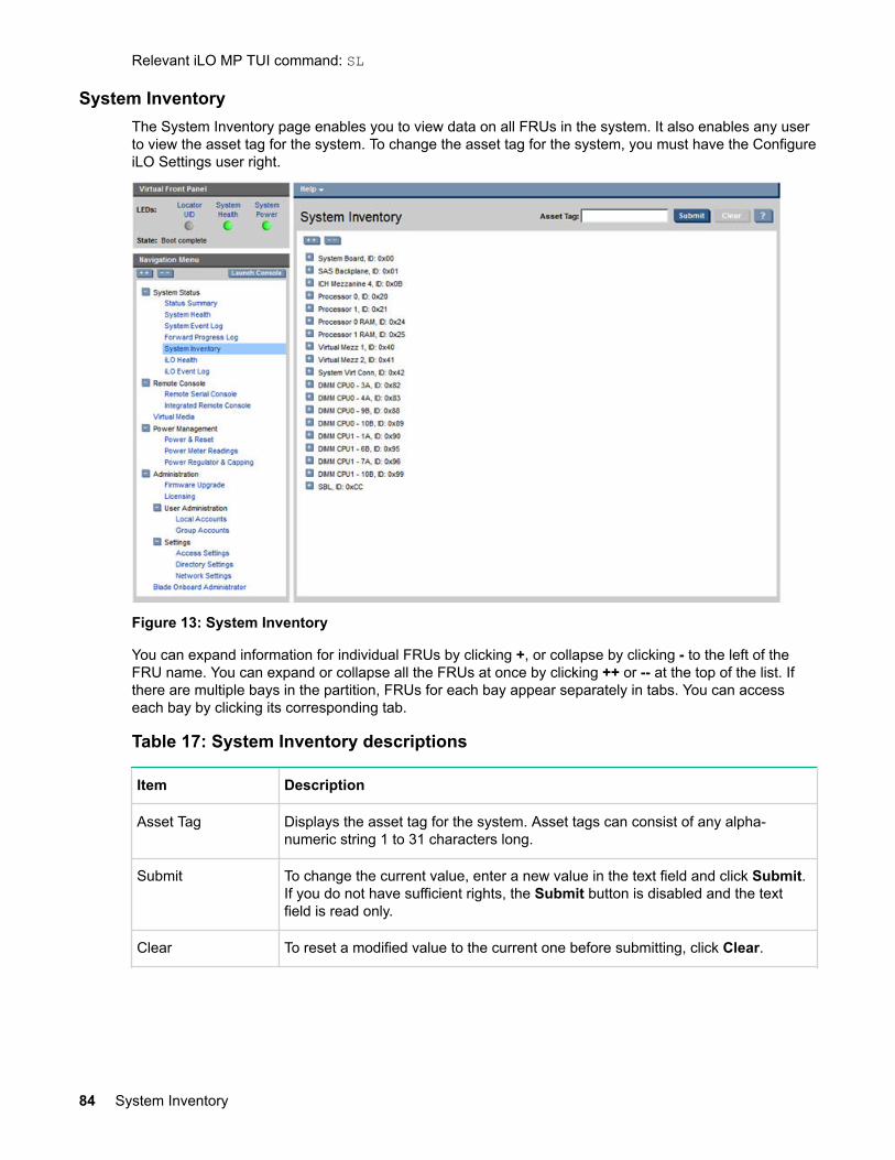
Relevant iLO MP TUI command: SL
System InventoryThe System Inventory page enables you to view data on all FRUs in the system. It also enables any userto view the asset tag for the system. To change the asset tag for the system, you must have the ConfigureiLO Settings user right.
Figure 13: System Inventory
You can expand information for individual FRUs by clicking +, or collapse by clicking - to the left of theFRU name. You can expand or collapse all the FRUs at once by clicking ++ or -- at the top of the list. Ifthere are multiple bays in the partition, FRUs for each bay appear separately in tabs. You can accesseach bay by clicking its corresponding tab.
Table 17: System Inventory descriptions
Item Description
Asset Tag Displays the asset tag for the system. Asset tags can consist of any alpha-numeric string 1 to 31 characters long.
Submit To change the current value, enter a new value in the text field and click Submit.If you do not have sufficient rights, the Submit button is disabled and the textfield is read only.
Clear To reset a modified value to the current one before submitting, click Clear.
84 System Inventory

iLO HealthThe iLO Health page enables you to reset the iLO or reset iLO to the default configuration and view theiLO Self Test Results. To issue either of the two reset iLO options, you must have the Configure iLOsettings user right. You can safely perform an iLO reset without affecting server operation.
Figure 14: iLO Health
Table 18: iLO Health descriptions
Item Description
Reset the iLO toDefaultConfiguration
Resets sets all iLO parameters to the default values.
Reset iLO All iLO parameters retain their current values. Note: iLO reset is disabled during afirmware upgrade.
Submit Submits your request to the system
iLO Self Test Results
NVRAM The status of non-volatile RAM.
EEPROM The status of the EEPROM.
Relevant iLO MP TUI commands: DC, XD -R
iLO Health 85

iLO Event LogThe log viewer enables you to view the contents of the iLO Event Log stored in nonvolatile memory.
Figure 15: iLO Event Log
Table 19: iLO 3 Event Log descriptions
Item Description
iLO 3 Event LogSummary
Displays alert level information.
iLO 3 Event Log Displays all the events corresponding to iLO 3 MP login/logout actions andrunning of iLO 3 MP commands.
Relevant iLO MP TUI command: SL
Remote Serial ConsoleThe Remote Serial Console enables you to securely view and manage a remote server. You can view andinteract with the boot-up sequence of an HPE server, perform maintenance activities in text mode, andmanage non-graphical mode operating systems.
To use this feature, you must have the Remote Console Access user right. To assign privileges to thisright, use the Administration>User Administration page.
86 iLO Event Log

Figure 16: Remote Serial Console
Remote Serial Console requires prior installation of Java Plug-in to be installed on the client system.
NOTE:
Pop-up blocking applications prevent Remote Serial Console from running. Before starting theRemote Serial Console, disable any pop-up blocking applications.
The iLO 3 mirrors the system console to the iLO 3 MP local, remote, and LAN ports. One console outputstream is reflected to all the connected console users. If several different terminal types are usedsimultaneously by the users, some users may see unexpected results. Only one mirrored user at a timehas write access to the console. Write access is retained until another user requests console writeaccess. To obtain console write access, press Ctrl-Ecf.
To ensure proper operation of the remote serial console, verify the following conditions:
• Your emulator can run the supported terminal type.• The iLO 3 terminal setting in the applet is a supported setting.• The operating system environment settings and your client terminal type are set properly.• All mirrored consoles are of the same terminal type for proper operation.
The setting in the Java applet (for example, HPterm, VT100, and so on) must match the console typeof the OS you are connecting to. A similar issue occurs when using CO (or CL) from the TUI menu. Youmust make sure your terminal emulator matches what is in the console log so that terminal-specificoutput does not garble the display.
IMPORTANT:
Do not mix hpterm and vt100 terminal types at the same time. If two collaborating users viewconsole output with different emulation modes set, clients see garbled results when the outputfrom the system is terminal specific.
Using iLO 3 87

To launch the applet and connect to the system serial console (Figure 17: Remote Serial Consolewindow on page 88), click Launch. After connecting to the console, you might have to log in to theoperating system to perform administration functions.
NOTE:
If Launch is disabled, you do not have the Remote Console Access user right. To add the userright, see User Administration.
Figure 17: Remote Serial Console window
Using this feature, you can do the following:
• View and interact with the boot sequence of your server.• Perform maintenance activities in text mode.• Manage nongraphical mode operating systems.
The console window remains open until you sign out of the iLO 3 interface using the provided link in thebanner, leave the iLO 3 site, or refresh the entire page.
The remote serial console provides the console, and the GUI provides the iLO 3 MP Main Menufunctionality.
Output from the console is stored in nonvolatile memory in the console log, regardless of whether or notany users are connected to a console.
88 Using iLO 3

TIP:
In Internet Explorer, the Tab key might cause the browser to change focus away from the applet. Toregain focus, click the applet window. If you want to use the Tab key, use the Zoom Out feature,available by clicking the Zoom In/Out button at the top of the applet window.
HP-UX example: Applications which care about the terminal type (install, SAM, vi, and so on) running onHP-UX use two methods to determine the terminal type: The $TERM shell environment variable. Theapplication directly queries the terminal (in this case, the write enabled terminal establishes the terminaltype).
Remote Serial ConsoleIntegrity iLO 3 contains a remote serial console that enables it to actually be the console hardware devicefor the operating system. This console is a serial interface between the host system and iLO 3. IntegrityiLO 3 converts the serial data stream to be available remotely through the remote serial console (a VT320Java applet). The remote serial console must be correctly enabled and configured in the host.
The remote serial console function is a bidirectional data flow of the data stream appearing on the serverserial port. Using the remote console paradigm, a remote user can operate as if a physical serialconnection is present on the server serial port.
With the remote serial console, an administrator can access a console application such as Windows EMSremotely over the network. Integrity iLO 3 contains the functional equivalent of the standard serial port(16550 UART) register set, and the iLO 3 firmware provides a Java applet that connects to the serverserial port. If the serial redirection feature is enabled on the host server, iLO 3 intercepts the data comingfrom the serial port, encrypts it, and sends it to the web browser applet.
For Linux users, the iLO remote serial console provides an important function for remote access to theLinux server. By configuring a Linux login process attached to the server serial port, you can use the iLOremote serial console to remotely log in to the Linux operating system over the network.
Integrated Remote ConsoleThe Integrated Remote Console (IRC) is a signed Direct X application which enables a user to securelymanage HPE Integrity Servers with Integrated Lights-Out. The IRC integrates keyboard, video, andmouse into a virtual interface providing an experience similar to that of the remote server graphicsconsole. With the IRC, you can view the server graphics display to directly interact with the server andperform maintenance activities as well as open and run applications on the server using the keyboard andmouse control. The console makes use of the hardware acceleration and advanced graphics featuresin .NET Framework. The console is launched using Microsoft ClickOnce technology.
The IRC window remains open until one of the following events occurs:
• You sign out of the iLO interface using the provided link in the banner• The IRC does not detect keyboard or mouse activity for the period configured as idle connection
timeout• Another user disconnects IRC
IRC requirements• The host operating system needs to supports IRC.• The client operating system needs to be Microsoft Windows.• Microsoft .NET Framework 3.5 or above needs to be installed. (available through Windows Update)• Firefox needs an Add-on to allow it to launch ClickOnce applications. Visit the Firefox Add-on site to
find the latest version of the Microsoft .NET Framework Assistant.• iLO Advanced Pack license needs to be installed.• The user needs iLO Remote Console Access and Virtual Power & Reset rights. These rights can be
enabled from the iLO User Administration pages.
Remote Serial Console 89

• The URL used to log into iLO needs to use the iLO certificate's Common Name (for example,https://<iLO Common Name>).
• If iLO is using an imported and trusted SSL Certificate, then client should be able to establish thecertificate chain of trust to launch IRC.
• If iLO is using a self-signed certificate generated during initial boot or generated by the user withcustom parameters, then the iLO certificate needs to be imported on to the client. (see detailedinstructions below).
NOTE:
In enhanced security mode (when "Enforce AES/3DES" option is enabled), TLS 1.0, TLS 1.1 andSHA1 are disabled by default. If the .Net framework or the .Net ClickOnce application used in theclient does not support TLS 1.2, IRC application download will fail. It is recommended to upgradethe Microsoft .Net framework. As an alternative, iLO Text User Interface command "SO" provides anoption "Enable TLS1" to enable TLS 1.0, TLS 1.1 and SHA1 in enhanced security mode (EnforceAES/3DES option is enabled).
Instructions for importing the iLO certificate on to the clientIf the IRC application download did not succeed, it is likely that the iLO certificate needs to be imported onto the client. This allows for a secure console session.
Procedure
1. First, login to the iLO web interface using Internet Explorer.a. If IE7 or IE8
Click the Certificate Error located after the URL in the pink box.
If IE 6.0
Click the yellow padlock in the bottom right hand corner.b. Click View certificates.c. Click Install Certificate….d. Click Next.e. Select Place all certificates in the following store.f. Click Browse.g. Select Trusted Root Certification Authorities.h. Click OK.i. Click Next.j. Click Finish.k. Click Yes.
2. Second, use the Common Name in the iLO certificate to log in to iLO using either Internet Explorer orFirefox.a. The “Common Name” is displayed on the login screen and also on the Access Certificate page.
The Common Name can be set to the iLO IP address, hostname, or fully-qualified hostname. If thedesired access method to iLO is not the current value in the iLO certificate's Common Name, go tothe Access Settings page and generate a new certificate with the desired Common Name. You willneed to reset the iLO and import the new certificate following the steps outlined above.
Configuration and usage suggestions• For better responsiveness, select plain wallpaper on the host server system.• Do not use an animated mouse pointer or enable “mouse trails” on the host server.
90 Instructions for importing the iLO certificate on to the client

• For best remote console performance, set the client screen resolution higher than the host server.• For security reasons, if you log into a host server through the IRC, you must log out before closing the
IRC.
IRC features• IRC maximum supported resolution is 1024 X 768 pixels.• IRC data is encrypted with the AES encryption algorithm.• IRC uses encryption and compression providing a secure, reduced bandwidth connection.
IRC limitations• IRC supports only a single user connection.• IRC does not yet provide identical virtualization of a Windows keyboard. Known issues are:
◦ No support for system level commands such as (ctrl) + (esc), (print screen).◦ No support for simultaneous mouse click and keystroke combinations.
• IRC application closes after the configured idle connection timeout if there is no keyboard or mouseactivity.
• IRC attempts to pick the best client display settings for that resolution, however some monitors mayhave trouble with the highest screen refresh rates supported by the clients video adapter. UseControl Panel/ Display/ Settings/ Advanced/ Monitor and select a lower screenrefresh rate.
Using the IRC
Procedure
1. Click the Launch button on the Integrated Remote Console page.
Figure 18: Integrated Remote Console
The following message appears when the IRC fails to launch:
IRC features 91

2. To view the Error Summary, click Details….If the following error message appears in the IRC log Error Summary section, then the certificate hasnot been imported:The underlying connection was closed: Could not establish trustrelationship for the SSL/TLS secure channel. + The remote certificate isinvalid according to the validation procedure.
3. If iLO is using an imported certificate, as long as the client can establish the certificate chain of trustand the requirements mentioned in IRC page are met, the application download should succeed.
4. If iLO is using a self-signed certificate generated during initial boot or generated by user with customparameters, connecting to the IRC requires several additional steps. To complete connection, see Instructions for importing the iLO certificate on to the client on page 90.
5. In enhanced security mode (when “Enforce AES/3DES“ option is enabled), TLS 1.0, TLS 1.1 andSHA1 are disabled by default. If the .Net framework or the .Net ClickOnce application used in theclient does not support TLS 1.2, IRC application download will fail. It is recommended to upgrade theMicrosoft .Net framework.
As an alternative, iLO Text User Interface command “SO“ provides an option “Enable TLS1“ to enableTLS 1.0, TLS 1.1 and SHA1 in enhanced security mode (Enforce AES/3DES option is enabled).
Once you successfully access the IRC, you will have full functionality to use the IRC.
Virtual MediaVirtual Media (vMedia) enables connections of a CD/DVD-ROM physical device or image file from thelocal client system to the remote server. The virtual device or image file can be used to boot the serverwith an operating system that supports USB devices. Virtual Media depends on a reliable network withgood bandwidth. This is especially important when you perform tasks such as large file transfers oroperating system installations.
The vMedia device can be a physical CD/DVD-ROM drive on the management workstation, or it can bean image file stored on a local disk drive or network drive.
Booting from the iLO 3 CD/DVD-ROM enables administrators to upgrade the host system ROM, upgradedevice drivers, deploy an operating system from the network drives, and perform disaster recovery offailed operating systems, among other tasks.
The iLO 3 device uses a client-server model to perform the vMedia functions. The iLO 3 device streamsthe vMedia data across a live network connection between the remote management console and the hostserver. The vMedia Java applet provides data to the iLO 3 as it requests it.
NOTE:
The iLO 3 vMedia is automatically disconnected if the iLO 3 MP is reset. Hewlett Packard Enterprisedoes not recommend using iLO 3 vMedia with firmware update tools such as HPOFM, which resetthe MP midway through the update process.
92 Virtual Media

Using iLO 3 virtual media devicesConnect client-based vMedia to a host HPE Integrity server blade through a graphical interface using asigned Java applet. Refusing to accept the applet certificate prevents browser-based vMedia fromfunctioning (a red X appears). It also prevents the remote console applet from functioning because it isalso signed using the same certificate.
NOTE:
You can use the vMedia applet only on x86 clients.
To access the iLO 3 vMedia devices using the graphical interface:
Procedure
1. Select Virtual Media. The Virtual Media page appears (Figure 19: Virtual Media on page 93).
Figure 19: Virtual Media2. To load the vMedia applet, click Launch. The vMedia applet loads in support of the vMedia device.3. At this point, you can connect to a virtual CD/DVD-ROM or USB key device or create an iLO 3 disk
image file.a. Check the USB Key for EFI Only box.b. Click Launch.c. Select Local Media Drive in the correct virtual media section.d. Select the drive letter of the desired USB key drive on your client PC from the menu. To ensure the
source diskette or image file is not modified during use, select the Force read-only access option.e. Click Connect. The connected drive icon and LED change state to reflect the current status of the
virtual Drive.
Using iLO 3 virtual media devices 93

NOTE:
When you disconnect the iLO 3 vMedia, you might receive a warning message from the hostoperating system regarding unsafe removal of a device. To avoid this warning, use the operatingsystem stop-device function before disconnecting it from the vMedia.
Virtual CD/DVD-ROMThe iLO 3 virtual CD/DVD-ROM is available during server boot for operating systems specified on theHewlett Packard Enterprise website at http://www.hpe.com/info/ilo.
Booting from the iLO 3 virtual CD/DVD-ROM enables you to deploy an operating system from networkdrives with DVDs or CDs that contain data in the El Torito Bootable CD format, as well as perform othertasks.
If the host server operating system supports USB mass storage devices, the iLO 3 virtual CD/DVD-ROMis also available after the host server operating system loads. Use the iLO 3 virtual CD/DVD-ROM whenthe host server operating system is running to upgrade device drivers, install software, and perform othertasks. Having the virtual CD/DVD-ROM available when the server is running can be especially useful ifyou must diagnose and repair a problem with the NIC driver.
The virtual CD/DVD-ROM can be the physical CD/DVD-ROM drive on the client system (which you arerunning on the web browser), or an image file stored on the client or network drive. For maximumperformance, HPE recommends using local image files stored either on the hard drive of your clientsystem or on a network drive accessible through a high-speed network link.
The iLO 3 vMedia CD/DVD-ROM appears to your operating system just like any other CD/DVD-ROM.When using the iLO 3 for the first time, the host operating system might prompt you to complete a NewHardware Found wizard.
NOTE:
This feature requires that the Java Plug-in 1.4.2 or later is installed.
This feature requires the Virtual Media right. If a user does not have the vMedia right, it can begranted from the User Administration page under the Administration tab by a user with Adminprivileges.
To use a physical CD/DVD-ROM drive in your client system:
Procedure
1. Select Virtual Media. The Virtual Media content page appears.2. To load the applet and connect to USB CD/DVD-ROM devices and disk image files available on the
client as virtual devices on the server, click Launch. The vMedia applet appears (Figure 20: VirtualMedia dialog box (before connection) on page 95).
NOTE:
Only one user and one device can be connected at a time.
IMPORTANT:
Only CD and DVD-ROM image files are supported.
If you use a USB key image file, you must select the Floppy/USB Key option. The USB keyimage file is not interchangeable with the CD or DVD-ROM and vice versa.
94 Using iLO 3

Figure 20: Virtual Media dialog box (before connection)3. Select Local Media Drive.4. Select the drive letter of the desired physical CD/DVD-ROM drive on your client system from the list.5. Click Connect. The connected drive icon and LED changes states to reflect the current status of the
virtual CD/DVD-ROM.
Figure 21: Virtual Media dialog box (after connection)
After you are connected, virtual devices are available to the host server until you close the vMediaapplet or sign out from a web session.
6. When you are finished using the virtual CD/DVD-ROM, disconnect the device from the host server orclose the applet.
NOTE:
The vMedia applet must remain open when using a vMedia device.
Using iLO 3 95

Virtual Media CD/DVD-ROM operating systemYou can view the list of supported browser and operating systems in the Quickspec document on theHewlett Packard Enterprise website.
The vMedia CD/DVD-ROM supports the following operating systems:
• UEFI console currently supports only El Torito bootable CD format media.• Windows Server 2003 or 2008:
The virtual CD/DVD-ROM displays automatically after the Windows operating system has recognizedthe mounting of the USB device. Use it as a locally attached CD/DVD-ROM device.
• Linux (Red Hat and SUSE)
On servers with a locally attached IDE CD/DVD-ROM, the virtual CD/DVD-ROM device is accessibleat /dev/cdrom1. However, on servers without a locally attached CD/DVD-ROM (such as the HPEIntegrity server blades) the virtual CD/DVD-ROM is the first CD/DVD-ROM accessible at/dev/cdrom.The virtual CD/DVD-ROM can be mounted as a normal CD/DVD-ROM device using: mount /mnt/cdrom1.
• HP-UX 11i
To recognize the hardware path and special files, run the ioscan -kfnC disk command.
To mount the virtual CD/DVD-ROM/image file on a directory, run the # mount <special filespath> /<dir-name> command.
• OpenVMS 8.3-1H1 and 8.4
NOTE:
Post operating system boot data format is dependent on the operating system.
Creating the iLO 3 disk image filesThe iLO 3 vMedia feature enables you to create CD and DVD image files within the same applet. Theimage files created are ISO-9660 file system images and El Torito bootable CD images. The performanceof the iLO 3 vMedia is faster when image files are used. The utility to create the iLO 3 CD/DVD-ROM diskimage files is integrated into the vMedia applet.
Store image files on your client computer or on a network drive that you can access from the client usinga fast network segment. A disk image file produces better performance than using a physical CD in yourclient computer.
To create image files from physical diskettes, CDs, or DVDs, use the Disk>Image option. The Disk>Imagebutton changes to Image>Disk when clicked. The Image>Disk option is not valid for a virtual CD/DVD-ROM image.
NOTE:
The iLO 3 Create Media Image utility does not currently support USB devices in Linux or NetWare.
To create an iLO 3 disk image file:
Procedure
1. In the Virtual CD-ROM section of the vMedia applet, select Local Image File.2. Select Local Media Drive.
96 Using iLO 3

Figure 22: Local image file dialog box3. To open the Create Media Image dialog box and locate the image file, enter the path or file name of
the image in the text box or click Browse.
Figure 23: Create media image dialog box4. Click Create Disk Image. The vMedia applet begins the process of creating the image file. This
process creates a file that emulates a CD/DVD-ROM on the local system. The process is completewhen the progress bar reaches 100%. To cancel the creation of an image file, click Cancel.
To insert the next CD during an operating system installation or any application installation with multipleimage files:
• To select the next image file or to replace the CD/DVD-ROM with the next CD/DVD-ROM, clickBrowse
• To continue the installation, click OK on the host server.
IMPORTANT:
Do not click Disconnect to select the next CD/DVD-ROM image file.
The connected drive icon and LED change states to reflect the current status of the virtual CD/DVD-ROM.After you are connected, virtual devices are available to the host server until you close the vMedia applet.When you are finished using the virtual CD/DVD-ROM, you can disconnect the device from the hostserver or close the applet. The vMedia applet must remain open when you use a vMedia device.
Using iLO 3 97

The iLO 3 vMedia CD/DVD-ROM appears like any other CD/DVD-ROM to your operating system. Whenyou use iLO 3 for the first time, the host operating system might prompt you to complete a New HardwareFound wizard.
Virtual USB keyThe iLO 3 vMedia devices connect to the host server using USB technology. Using USB also enablesnew capabilities for the iLO 3 vMedia devices when connected to USB-supported operating systems.Integrity iLO 3 v1.00 supports Virtual USB flash as a read-only device for use only with EFI, not with aclient operating system.
The USB key can be the physical USB key drive on which you are running the web browser, or an imagefile stored on your local hard drive or network drive. For maximum performance, HPE recommends usingthe local image files stored either on the hard drive of your client PC or on a network drive accessiblethrough a high-speed network link.
To use the USB key drive in your client PC:
Procedure
1. Click Launch.2. Select Local Media Drive in the correct virtual media section.3. Check the USB box on the right-hand side of the window.4. Select the drive letter of the desired USB key drive on your client PC from the menu. To ensure the
source diskette or image file is not modified during use, select the Force read-only access option.5. Click Connect. The connected drive icon and LED change state to reflect the current status of the
virtual Drive.
Figure 24: Virtual USB key
To use an image file:
1. Click Launch.2. Within the virtual USB key section of the vMedia applet, select Local Image File.3. In the text-box, enter the path or file name of the image, or to locate the image file by using the
Choose Disk Image File dialog, click Browse. To ensure the source diskette or image file is notmodified during use, select Force read-only access.
98 Using iLO 3

IMPORTANT:
You must select the USB key image file with this option.
If you use CD or DVD-ROM image files, you must select the CD/DVD-ROM option. The CD orDVD-ROM option is not interchangeable with the USB key image file and vice versa.
4. Click Connect. The connected drive icon and LED change state to reflect the current status of thevirtual USB key drive. When connected, the virtual devices are available to the host server until youclose the vMedia applet.
5. When you are finished using the virtual USB key, disconnect the device from the host server or closethe applet.
Performance• A disk image file results in better performance than a physical drive.• Store the image files on the client or on a network drive accessed using a fast network segment.• The drive-connected icon and LED change state to reflect the connection status of the virtual drive.• The connected drive appears with data on the host while the nonconnected device appears as an
empty drive.• To ensure that the source diskette or image file is not modified during use, you can use the force read-
only access.• The vMedia applet connects to iLO 3 using port number 17988.
Server blade Onboard Administrator DVDThe following requirements apply for all server blades:
• The USB key is only available through the applet in the iLO 3 web GUI.• You can connect vMedia using either the BladeSystem Onboard Administrator DVD or the applet in
iLO web GUI. You cannot use both connection methods at the same time.• If you need to install operating systems using both CD and USB key, you must connect both from the
applet in the iLO 3 web GUI.
Virtual Media applet timeoutThe vMedia applet does not timeout when it is connected to a host server. The vMedia applet mustremain open when using a vMedia device. The vMedia applet closes when you sign out of the iLOinterface using the provided link in the banner, leave the iLO site, or refresh the entire page.
Supported operating systems and USB support for virtual MediaTo use vMedia devices, your operating system must support USB mass storage devices.
Different operating systems provide different levels of USB support. Integrity iLO 3 uses the built-in USBdrivers of the operating server. The level of USB support in the operating system affects the level ofsupport for iLO 3 vMedia. In general, any operating system issues that affect a USB CD/DVD-ROM drivealso affect iLO 3 vMedia.
The HPE server ROM provides support during server boot for vMedia with the El Torito bootable CDformat.
You can view the list of supported operating systems on the Hewlett Packard Enterprise website at https://www.hpe.com/h20195/v2/getpdf.aspx/c04154454.pdf.
Java Plug-in versionThe vMedia feature requires prior installation of Java Plug-in 1.4.2_10, 1.5 or 1.6.0. With iLO 3 firmwareversion 02.00.0x or later, the virtual media applet should work with Java 1.7 and Java 1.8.
Supported operating systems and USB support for virtual Media 99

Client operating system and browser support for virtual mediaYou can view the list of supported client operating systems and browser support on the Hewlett PackardEnterprise website at http://www.hpe.com/info/Integrity_Servers-docs. The browser and OSinformation is located in the Quickspec document located on this website.
Power ManagementThe iLO 3 power management feature enables you to view and control the power state of the server,monitor power usage, and monitor the processor. You must have the Virtual Power & Reset user right tochoose options on the power pages except where stated that the Configure iLO Settings user right isrequired.
The Power Management menu has the following options:
• Power & Reset• Power Meter Readings• Power Regulator & Capping
The pages are automatically refreshed every 10 seconds.
Power & ResetThe Power & Reset page enables you to view and control the power state and power options of theserver. To choose options on this page, except where stated that the Configure iLO Settings right isrequired, you must have the Virtual Power & Reset right.
Figure 25: Power & Reset
For information on how to set the power management options in the OA, see the HPE BladeSystemOnboard Administrator User Guide on the Hewlett Packard Enterprise website.
100 Client operating system and browser support for virtual media

Table 20: Power & Reset description
Item Description
System Power The current power state of the system.
System Power Control Power control access enables you to issue the following options for remotecontrol of the system power:
Graceful Power Off
The iLO 3 sends a signal to the operating system to shutdown before turningoff system power. Supported by IPF operating systems.
Force Power Off
Turns system power off. This action is equivalent to forcing the systempower off with the front panel power switch. No signal is sent to theoperating system to bring the software down before power is turned off. Topower off the system properly, shut down the operating system beforeissuing this command.
Force System Reset with Crash Dump (TOC/INIT)
Causes the system to be reset through the INIT or TOC signal. All systemprocessing and I/O activity is irrecoverably halted. The processors aresignaled to dump state on the way down.
Force System Reset
Causes the system to reset through the RST signal. All system processingand I/O activity is irrecoverably halted. The effect of this command is verysimilar to cycling the system power. The operating system is not notified, nocrash dump is taken on the way down, and so on.
Force Power Cycle
Turns system power off, waits 30 seconds, then turns the system powerback on.
System PowerRestore Settings
The power restore policy determines how the system behaves when AC powerreturns after an AC power loss. To issue these options, you must have theConfigure iLO Settings user right.
Restore Previous Power State
The power is restored to the state that was in effect when AC power wasremoved or lost.
Automatically Power On
The system is powered on after AC power is applied.
Remain Powered Off
The system remains powered off after AC power is applied. To power on thesystem, you must push the system power switch or choose the Power Onoption under System Power Control.
Table Continued
Using iLO 3 101
Item Description
Power On Delay NOTE:
The power on delay feature is only available on rackmount servers. Forserver blades, the OA handles the power on delay feature.
The power on delay specifies how many seconds the system will delay poweron after AC power is applied. The power on delay is applicable when the powerrestore policy is set to Restore Previous Power State or Automatically PowerOn. The default power on delay is 0 seconds.
Wake-On-LAN Enables or disables Wake-On-LAN for the system LANs.
NOTE:
Wake-On-LAN (WOL) is not supported with Integrity servers runningWindows or OpenVMS environments. WOL is supported with IntegrityBL860c i2/i4/i6, BL870c i2/i4/i6, and BL890c i2/i4/i6 Server Bladesrunning HP-UX 11i v3. The supported remote power-on solution forWindows and OpenVMS is iLO. For details, see the User Service Guidefor your server.
Relevant iLO MP TUI commands: PC, PR, PS, WOL
Power Meter ReadingsThe Power Meter Readings page enables you to view the Power Meter Readings over time.
Power meter readings shares information with Insight Power Manager.
The Power Meter Readings page has two graphs: a 24-Hour History Graph and a 20-Minute HistoryGraph.
102 Power Meter Readings

Figure 26: Power Meter Readings
IMPORTANT:
Power consumption data readings are dependent on the configuration, architecture, components,and levels of activity of the server at any given time.
Using iLO 3 103

Table 21: Power Meter Readings description
Item Description
History Graphs The graphs display recent server power usage. The graph data is resetwhenever the iLO MP is reset. Samples are taken in 5 minute and 10 secondtime increments.
24-Hour History Graph
24-hour display with samples taken every 5 minutes.
20-Minute History Graph
20-minute display with samples taken every 10 seconds.
Each sample includes the power usage, power regulator mode, temperature,and time stamp of when the sample was taken. You can display this informationby positioning the mouse over a sample on each graph. The peak, average,and cap samples display by default. You can display or hide peak, average, andcap samples on the graphs by toggling the appropriate checkbox.
Peak
Samples are red and appear in the background.
Average
Samples are blue.
Minimum
Samples are gray and appear in the foreground.
Cap
Samples are black.
Power Units You can display the samples in either watts or Btu/hr by selecting theappropriate units in the Show values in menu.
Table Continued
104 Using iLO 3

Item Description
Current State Displays the current power readings.
• Present Power Reading• Present Power Cap• Power Regulator Mode
Displays the power reading at iLO initialization.
• Power Input Voltage
Power History Displays power history collected in 5 minute, 20 minute, and 24 hourincrements.
Peak
Displays the highest power usage of the samples collected.
Average
Displays the average power usage of all the samples collected.
Minimum
Displays the lowest power usage of the samples collected.
Power Regulator & CappingThe Power Regulator & Capping page enables you to view and control the power regulator and powercapping settings for the server. To change this setting, you must have the Configure iLO Settings userright.
The Power Regulator feature is available on systems where support is provided by the operating system,processors, PDH (processor dependant hardware), SFW (System Firmware), and iLO firmware. For moreinformation on power regulation support, see your server model Quickspecs document.
Power Regulator & Capping 105

Figure 27: Power Regulator & Capping
106 Using iLO 3

Table 22: Power Regulator & Capping description
Item Description
Power RegulatorSettings
Dynamic Power Savings Mode
This mode enables the system to dynamically change processor p-stateswhen needed based on current operating conditions. The implementation ofthis mode is operating system specific. For details, see your operatingsystem documentation.
Static Low Power Mode
This mode sets the processor to the lowest supported power consumptionstate and forces it to stay in this lowest state.
Static High Performance Mode
This mode sets the processor to the highest supported performanceprocessor state and forces it to stay in this highest state.
OS Control Mode
This mode configures the server to enable the operating system to controlthe processor p-states. Use this setting to put the Operating System(including OS-hosted applications) in charge of power management.
Power CappingSettings
Power Cap Value
The power cap value in watts or Btu/hr and percentage.
Maximum Power Rating
Maximum power cap allowed.
Peak Observed Power
A power cap at or above this value should have no impact on serverperformance.
Minimum Observed Power
Idle power consumption and lowest possible power cap. A power cap nearminimum power might have significant impact on server performance.
Show values in Btu/hror Show values inwatts
Select how you want the values to display.
NOTE:
Power caps set to less than 50% of the difference between peak observed power and minimumobserved power might become unreachable due to changes in the server. Power caps set to lessthan 20% are not recommended, and might cause the server to reboot or the server OS to stopresponding.
Relevant iLO MP TUI command: PM
AdministrationThe Administration menu enables you to access the following pages:
Administration 107

• Firmware Upgrade• Licensing• Local Accounts• Group Accounts• Access Settings• Directory Settings• Network Settings• Certificate Settings• WS-MAN Settings• BladeSystem Onboard Administrator (OA) (Available only for server blade)
Firmware UpgradeThe Firmware Upgrade page enables you to upgrade the iLO 3 and system programmable firmware. Touse this feature, you must have the Configure iLO Settings user right.
Figure 28: Firmware Upgrade
NOTE:
Bundles containing firmware (iLO firmware, System firmware, and/or System programmablehardware) that may be installed using this Firmware Upgrade page are available for download. It isimportant to check the compatibility of the firmware revisions in the bundle with the current revisionson the system prior to updating. Use of the HP SUM firmware upgrade tool will automaticallyperform compatibility checking.
To find appropriate bundles for this system:
108 Firmware Upgrade

Procedure
1. On the https://www.hpe.com/us/en/support.htmlwebsite, go to HPE Servers, Storage andNetworking under Product Support.
2. Search for this server product, for download drivers and software.3. Choose your operating system, if you want to get a bundle that can be installed from the operating
system; or, choose OS independent (BIOS, Firmware, Diagnostics, etc.), if youwantto get a bundleto install using this SUM, Firmware Upgrade page, a CD,or using UEFI with the systemdown.
4. Locate Firmware - System or Firmware - Management in the list of offerings. To perform theupgrade, follow the instructions under the description for the bundle.
Perform the upgrade through the MP LAN by http(s). Enter the information required for the upgradethrough the FW command interface.
To download and upgrade the firmware package from the Hewlett Packard Enterprise website, see https://www.hpe.com/us/en/support.html.
IMPORTANT:
When performing a firmware upgrade that contains system programmable hardware, you mustproperly shut down any operating system that is running before starting the firmware upgradeprocess.
CAUTION:
If the firmware upgrade process is interrupted at any time, you must repair or replace the core I/O.
At the end of the upgrade process, the MP is reset. Reconnect and log in.
If a firmware request is pending when you enter the FW command, a SYSREV table appears. You will beprompted to either cancel the firmware upgrade request or exit. Follow the prompts on the screen.
The FW command upgrades iLO MP or specific system programmable firmware.
• If only upgrading the iLO MP firmware, the iLO MP automatically resets upon successful completiondropping all iLO MP LAN connections. This upgrade will not affect server operation if it is for iLO MPonly.
• If this upgrade is system programmable firmware, the upgrade can be completed without resetting iLO,however, the server needs to be reset for the pending system programmable firmware revisions tobecome active. Resetting the server to activate pending firmware can take up to 10 minutes before theserver begins to boot.
After the upgrade, reconnect and log in.
TIP:
Before performing certain iLO 3 functions, verify that you have the supported firmware versionrequired to carry out the task.
LicensingThe Licensing page displays the factory-installed iLO 3 Advanced Pack License Key.
The iLO 3 firmware comes with a full-featured permanent default Advanced Pack Licensing Key built in.No additional licensing is necessary. The New Permanent Licensing Key field is reserved for future use.This field is unused in Integrity iLO 3 v1.00.
Licensing 109

IMPORTANT:
The HPE ProLiant iLO 3 Advanced Pack Licensing Key will not work on an HPE Integrity serverblade and vice versa.
Figure 29: Licensing
The following Advanced Pack features are available in this firmware release:
• Virtual Media• Directory Services Integration for iLO 3 user management using LDAP-based directory services• Schema-free LDAP based directory services (LDAP-lite)• Power Meter Readings• Integration with Insight Power Management
These features can change without notice. Not all features are supported by all operating systems. Not allfeatures are supported by all platforms. Some features require configuration and additional support.
Table 23: Licensing description
Item Description
Licensing Key Status Displays the status of the license.
Install Date Displays the date the license was installed.
Licensing Key Displays the license key.
Table Continued
110 Using iLO 3

Item Description
New PermanentLicensing Key
Optional field reserved for future use. This field is unused in Integrity iLO 3v1.00.
Submit Submits the key for activation.
Cancel Cancels the action.
User Administration>Local AccountsThe Local Accounts page displays the current list of local users, their privilege rights and whether thoserights are enabled or disabled. This page enables you to modify the user configuration of iLO 3. To usethis feature, you must have the Administer User Accounts user right.
User Administration>Local Accounts 111

Figure 30: Local Accounts
The default user is Administrator. The Administrator user has all access rights.
112 Using iLO 3

Table 24: Local Accounts description
Item Description
Select User To edit or delete a user account, select an existing user from the list of usernames and click Edit or Delete to either edit or delete that user account.
New To create a new user account, click New. This opens a page that enables youto enter account information for the new user. By default, a new user is grantedthe Remote Console Access and Virtual Media rights. The operating mode isset to multiple logins, and the user is enabled.
Edit Click this button after selecting the user account to modify or to add a newaccount. For an existing account, you can modify any of the parameters shown,provided the user has sufficient privileges.
Table Continued
Using iLO 3 113

Item Description
Clicking Edit or New brings up a page that enables a user to enter the followinguser account information:
Login ID
This field is required. This is the name that must be used when logging in tothe iLO MP. The Login ID must be unique. The maximum length is 24characters.
Password
This field is required. The password must be provided when logging in toiLO 3. The password must be a minimum of 5 characters and can contain amaximum of 24 characters.
Password Confirmation
This field is required. The password must be provided a second time forverification.
User Name
This field is required. This name appears in the user list and on the homepage. It is not necessarily the same as the Login ID. The User Name mustbe unique. The maximum allowed length is 24 characters.
Workgroup
This field is optional, and can be initialized to an intuitive name.
Access Rights
iLO MP user privileges control user access to the iLO MP functions that auser can perform. You can configure iLO 3 users to have any (or all) of thefollowing privileges: Remote Console Access, Virtual Power & Reset,Configure iLO Settings, Administer User Accounts, and Virtual Media.
For more information on access rights, see the User Rights page locatedunder the Help tab.
Operating Mode
Multiple logins allow a user to log in more than once. If the mode is Single,the state is changed to disabled after the first login.
User Enabled/Disabled
Enabled allows a user to log in to the iLO MP. If disabled is selected, theuser will not be able to log in to the iLO MP.
Delete Click this button after selecting the user account to delete. If you do not havethe User Administration Access right, this button is disabled.
114 Using iLO 3

NOTE:
You must configure the HPE System Insight Manager group actions feature for iLO 3 to use anexisting iLO user name.
To configure, manually edit the MpTools.xml file and replace the <execute-as-user> attribute withan existing user name on the iLOs. This new user name must have all access rights. To find theMpTools.xml file, look in the tools directory on the Central Management Server.
Additionally, iLO 3 supports user accounts created for login from the BladeSystem OnboardAdministrator. These user accounts appear as OAtmp#, where # is a number from 1-5. Removingthe BladeSystem Onboard Administrator user accounts is not recommended.
Relevant iLO MP TUI command: UC
Group AccountsThe Group Accounts page enables you to enter one or more directory groups by specifying thedistinguished name of the group and privileges that can be granted to users who are members of thatgroup. To use this feature, you must have the Configure iLO Settings user right.
Group administration information must be configured when the directory is enabled with the defaultschema.
When a user attempts to log in to iLO 3, iLO 3 reads that user’s directory name in the directory todetermine the groups that include the user as a member. The iLO 3 compares this information with a listof groups configured by the user. The rights of all the matched groups are combined and assigned to thatuser.
Group Accounts 115

Figure 31: Group Accounts
116 Using iLO 3

Table 25: Group Accounts description
Item Description
Administrator Click this radio button and click Edit to open a page that enables you to changesettings for the Administrator group.
User Click this radio button and click Edit to open a page that enables you to changesettings for the User group.
Custom (1,2,3,4) Click one of these radio buttons and click Edit to open a page that enables youto change settings for the chosen Custom group.
Clear Cancels the action.
Relevant iLO MP TUI command: LDAP
Access SettingsThe Access Settings page enables you to access the following tabs:
• LAN• Serial• Login Options• Login Security Banner• Encryption
LANThe LAN tab enables you to modify LAN settings. To use this feature, you must have the Configure iLOSettings user right.
Figure 32: LAN
Access Settings 117

Table 26: LAN description
Item Description
Telnet You can enable or disable Telnet access to iLO 3 using the enable or disableoption. This does not affect the IP configuration or the ability of iLO 3 to performupgrades over the LAN. The Telnet port number is 23. You cannot change it.
NOTE:
Integrity iLO 3 ships with Telnet disabled by default.
SSH You can enable or disable SSH access to the iLO 3 using the enable or disableoption.
The default SSH port number is 22. You can configure this port number to avalue in the range 2000-2400. If the port number is modified, it takes effect thenext time iLO 3 is rebooted. To secure an SSH connection, select Enable andensure that an SSH key pair has been generated.
SSH is an industry-standard client-server connectivity protocol that provides asecure remote connection. The iLO 3 firmware supports:
• SSH2 implementation• Authentication algorithms RSA and DSA• Encryption algorithms 3DES-CBC, AES128-CBC, AES256-CBC, and
AES256-CTR• Integrity algorithms HMAC-SHA256, HMAC-SHA1, and MD5.• When 'Enforce AES/3DES' is enabled, the weaker ciphers will be disabled.
Key Pair Status Indicates if a key pair has been generated previously. To generate a new SSHkey pair, check Generate New Key Pair and click Submit.
Web SSL You can enable or disable the web SSL access to iLO 3 using the enable ordisable option.
The port value is 443. You cannot change it.
To make an SSL connection, a valid SSL Certificate is required. For SSLCertificate status and related configuration, please visit SSL Certificate Settingspage under Administration > Settings
Certificate Status The iLO MP auto generates an SSL certificate when it is first powered on atinitial installation. It is expected that you will generate a new certificate withvalid information when you log in. The certificate status indicates if a certificatehas been generated previously. To generate a new certificate, select GenerateNew Certificate, fill in the fields, and click Submit.
Remote SerialConsole
The Remote Serial Console default port value is 2023. You can configure it to avalue in the range 2000-2400. If the port number is modified, it takes effect thenext time iLO 3 is rebooted.
Integrated RemoteConsole
The Integrated Remote Console default port value is 17990. You cannotchange it.
Table Continued
118 Using iLO 3

Item Description
Virtual Media The Virtual Media default port value is 17988. You cannot change it.
Submit Submits the information.
Clear Cancels the action.
Relevant iLO MP TUI commands: LC, SA, SO
SerialThe Serial tab enables you to set the serial port parameters. To change the external serial port mode, theiLO baud rate, and the iLO flow control settings, you must have the Configure iLO Settings user right.
Figure 33: Serial
Table 27: Serial description
Item Description
Mode of Operation Enables you to set the local serial mode of operation to either the iLO MP,Auxiliary UART mode or Persistent Auxiliary UART mode . Switching to AUXUART mode when MP LAN access is disabled requires a push-button reset ofthe iLO 3 Physical Presence button to return to iLO 3 mode. Persistent AuxillaryUART mode is same as Auxillary UART mode, but the serial port will not revertiLO3 MP mode after AC power loss. If baud rate settings are not consistentbetween the serial port and the attached serial device, communication issuesoccur.
iLO Bit Rate in Bitsper Second
Enables you to set the iLO 3 baud rate. Input and output data rates are thesame. The iLO 3 default baud rate is 9600 bps, 8 bits, 1 stop, no parity.
Flow Control Enables you to set the iLO 3 flow control. Flow control can be through hardwareor software. Hardware uses RTS/CTS. Software uses Xon or Xoff.
Table Continued
Serial 119

Item Description
Submit Submits the information.
Clear Cancels the action.
Relevant iLO MP TUI command: CA
Login OptionsThe Login Option tab enables you to modify the security options of iLO 3. To use this feature, you musthave the Configure iLO Settings user right.
Figure 34: Login Options
Table 28: Login Options description
Item Description
Login Timeout inMinutes
If a user remains at the MP login: prompt for longer than the timeout, iLO 3disconnects the user from SSH or Telnet. The default value is 1 minute; it canbe configured to a value in the range of 1 to 5 minutes. This timeout does notapply to users who have successfully logged in to iLO 3. The timeout value inminutes is effective on all ports, including local ports.
Password FaultsAllowed
Sets a limit on the number of password faults allowed when logging in to iLO 3.The default number of password faults allowed is three. If a greater number offaults is detected, the user is disconnected. It can be configured to a value inthe range of 1 to 10.
Security OverrideMode
Can be used to disable Security Override mode at any time before the 15-minute override timeout. Security Override mode can be disabled only when setby a Physical Presence button push, not when the Security Override switch isset. You cannot use this field to enable Security Override mode. The enable/disable buttons are gray unless security override is in effect.
Table Continued
120 Login Options
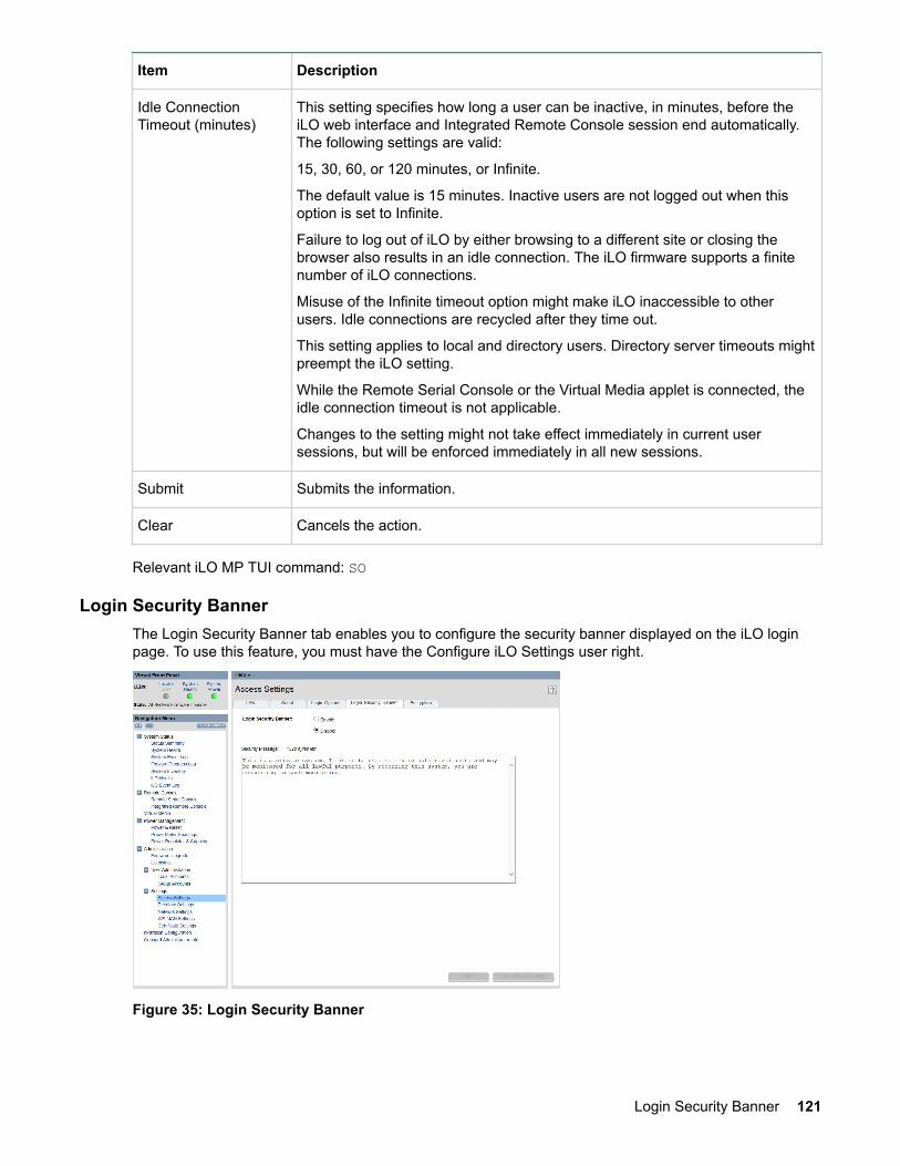
Item Description
Idle ConnectionTimeout (minutes)
This setting specifies how long a user can be inactive, in minutes, before theiLO web interface and Integrated Remote Console session end automatically.The following settings are valid:
15, 30, 60, or 120 minutes, or Infinite.
The default value is 15 minutes. Inactive users are not logged out when thisoption is set to Infinite.
Failure to log out of iLO by either browsing to a different site or closing thebrowser also results in an idle connection. The iLO firmware supports a finitenumber of iLO connections.
Misuse of the Infinite timeout option might make iLO inaccessible to otherusers. Idle connections are recycled after they time out.
This setting applies to local and directory users. Directory server timeouts mightpreempt the iLO setting.
While the Remote Serial Console or the Virtual Media applet is connected, theidle connection timeout is not applicable.
Changes to the setting might not take effect immediately in current usersessions, but will be enforced immediately in all new sessions.
Submit Submits the information.
Clear Cancels the action.
Relevant iLO MP TUI command: SO
Login Security BannerThe Login Security Banner tab enables you to configure the security banner displayed on the iLO loginpage. To use this feature, you must have the Configure iLO Settings user right.
Figure 35: Login Security Banner
Login Security Banner 121

Table 29: Login Security Banner description
Item Description
Login Security Banner To enable or disable the security banner displayed on the iLO login page.Login Security Banner is disabled by default.
Security Message To customize the security message, enter a custom message in theSecurity Message text box.
The byte counter above the text box indicates the remaining number ofbytes allowed for the message. The maximum is 1,500 bytes.
Submit Submits the information
Use Default Message To restore the security message to the default text that iLO uses.
Figure 36: iLO login page with default Security Banner
EncryptionThe Encryption tab enables you to enable or disable enhanced network security mode.
122 Encryption

Figure 37: Encryption
Table 30: Encryption description
Item Description
CurrentCipher
Shows the cipher that has been negotiated and is being used by the current web GUIsession.
EnforceAES/3DESencryption
When this option is enabled, iLO will try to negotiate the strongest encryption algorithmsand will not use any weak encryption algorithms for Web GUI and SSH connections. Bydefault, it is disabled.
iLO prefers AES256, AES128 and 3DES algorithms for encryption in the same order asspecified.
Submit Submits the information.
Cancel Cancels the action.
Relevant iLO MP TUI command: so
Certificate SettingsThe Certificate Settings page enables you to access the following tabs:
• SSL Certificate• Import Certificate• Generate Certificate
SSL Certificate
The SSL Certificate tab displays the details of the SSL certificate that is currently being used by iLO forweb GUI connections.
Certificate Settings 123

Figure 38: SSL Certificate
The iLO MP auto generates an SSL Certificate when it is first powered on at initial installation. It isexpected that you will generate or import a new certificate with valid information when you log in. Thecertificate status indicates if the certificate has been generated or imported previously.
To import a certificate with user defined parameters, signed by trusted Certificate Authority (CA), visitImport Certificate tab. To generate a new iLO self-signed certificate with user defined parameters, visitGenerate Certificate tab.
Import Certificate
The Import Certificate tab enables you to generate a Certificate Signing Request (CSR) and to import acertificate signed by a trusted Certificate Authority (CA) into iLO for a secure SSL connection for web GUIinterface of iLO3.
Figure 39: Import Certificate tab
124 Using iLO 3

Table 31: Import Certificate description
Column Head Column Head
Generation of CSR The CSR status indicates if a Certificate Signing Request (CSR) has beengenerated.
To generate a new CSR, fill in the fields shown and select Generate CSR. Thisoperation might take anywhere from 1 to 10 minutes. Please wait for theoperation to complete and the page will refresh automatically.
The generated CSR will be in base-64 encoded PKCS #10 format. SelectDisplay CSR to view or copy CSR.
The CSR can be sent to a Certificate Authority (CA). The CA will process therequest and provide a signed certificate that can be imported into iLO.
Import a Certificate The iLO security features can be enhanced by importing a trusted certificate.
Use the procedure mentioned above to generate a CSR and get a signedCertificate from a trusted Certificate Authority.
To import this certificate into iLO, click on Import Certificate button. Paste thecertificate contents into the Window that pops up and click on Import button.
You must restart iLO after importing a certificate. When iLO comes back, it willstart using the imported certificate for all SSL connections.
NOTE:
• Certificate contents to be imported has to be in Base64-encoded (.pem)format. iLO supports certificates that are up to 3KB in size.
• A certificate works only with the keys generated with its correspondingCertificate Signing Request (CSR). If another CSR is generated beforethe certificate that corresponds to the previous CSR is imported, thecertificate Import might fail. In that case, a new certificate thatcorresponds to the new CSR must be obtained and imported into iLO.
Figure 40: Importing SSL Certificate
Using iLO 3 125

Generate Certificate
The Generate Certificate tab enables you to generate a new SSL Certificate with the parameters definedby you.
Figure 41: Generate SSL Certificate
To generate a new certificate, fill in the fields shown and select Generate Certificate. You must restart theiLO MP after you generate a new certificate.
This certificate will be valid for 2 years. The system alerts you when the certificate is about to expire or ithas already expired. You will need to generate a new certificate before you can continue.
Directory Settings>Current LDAP ParametersThe Current LDAP Parameters page enables you to edit the directory parameters. To use this feature,you must have the Configure iLO Settings user right.
126 Directory Settings>Current LDAP Parameters

Figure 42: Current LDAP Parameters
Using iLO 3 127

Table 32: Current LDAP Parameters description
Item Description
DirectoryAuthentication
Choosing enable or disable, activates or deactivates directory support on iLO 3:
Enable with Extended Schema
Selects directory authentication and authorization using directory objectscreated with HPE schema. Select this option if the directory server has beenextended with the HPE schema.
Enable with Default Schema
Selects directory authentication and authorization using user accounts in thedirectory which has not been extended with the HPE schema. Useraccounts and group memberships are used to authenticate and authorizeusers. In the Administration>User Administration>Group Accountspage, configure one or more directory groups by entering the GroupDistinguished Name of the group and the rights granted to users who aremembers of that group. You must configure data in the Group Administrationpage after you select this.
Disable
Deactivates directory support on this iLO 3.
Local User Accounts Includes or excludes access to local iLO 3 user accounts. Locally-stored useraccounts can be active while LDAP directory support is enabled. If local useraccounts are enabled, you may log in to the iLO 3 using locally-stored usercredentials. If they are disabled, access is limited to valid directory credentialsonly.
Directory Server IPAddress
Displays the IP address or hostname of the directory server.
Directory ServerLDAP Port
Displays the port number for the secure LDAP service on the server. Thedefault value for this port is 636. It can be configured to a value in the range2000-2400.
iLO DistinguishedName
Displays the Distinguished Name of iLO 3, specifies where this iLO 3 instanceis listed in the directory tree.
Example: cn=MP Server,ou=Management Devices,o=hp
Table Continued
128 Using iLO 3
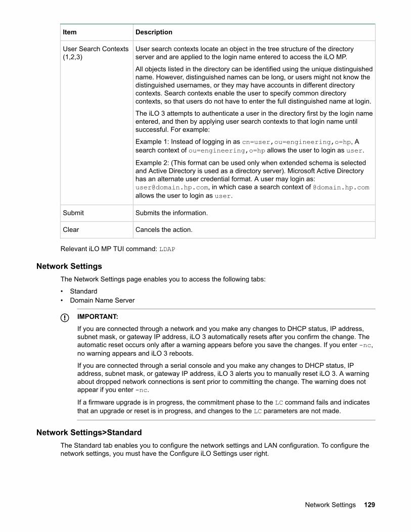
Item Description
User Search Contexts(1,2,3)
User search contexts locate an object in the tree structure of the directoryserver and are applied to the login name entered to access the iLO MP.
All objects listed in the directory can be identified using the unique distinguishedname. However, distinguished names can be long, or users might not know thedistinguished usernames, or they may have accounts in different directorycontexts. Search contexts enable the user to specify common directorycontexts, so that users do not have to enter the full distinguished name at login.
The iLO 3 attempts to authenticate a user in the directory first by the login nameentered, and then by applying user search contexts to that login name untilsuccessful. For example:
Example 1: Instead of logging in as cn=user,ou=engineering,o=hp, Asearch context of ou=engineering,o=hp allows the user to login as user.
Example 2: (This format can be used only when extended schema is selectedand Active Directory is used as a directory server). Microsoft Active Directoryhas an alternate user credential format. A user may login as:[email protected], in which case a search context of @domain.hp.comallows the user to login as user.
Submit Submits the information.
Clear Cancels the action.
Relevant iLO MP TUI command: LDAP
Network SettingsThe Network Settings page enables you to access the following tabs:
• Standard• Domain Name Server
IMPORTANT:
If you are connected through a network and you make any changes to DHCP status, IP address,subnet mask, or gateway IP address, iLO 3 automatically resets after you confirm the change. Theautomatic reset occurs only after a warning appears before you save the changes. If you enter -nc,no warning appears and iLO 3 reboots.
If you are connected through a serial console and you make any changes to DHCP status, IPaddress, subnet mask, or gateway IP address, iLO 3 alerts you to manually reset iLO 3. A warningabout dropped network connections is sent prior to committing the change. The warning does notappear if you enter -nc.
If a firmware upgrade is in progress, the commitment phase to the LC command fails and indicatesthat an upgrade or reset is in progress, and changes to the LC parameters are not made.
Network Settings>StandardThe Standard tab enables you to configure the network settings and LAN configuration. To configure thenetwork settings, you must have the Configure iLO Settings user right.
Network Settings 129

NOTE:
If valid changes are made to the DHCP Status, IP Address, Subnet Mask, or Gateway Address, andthe changes are submitted, a reset of iLO 3 is required for the changes to take effect.
Figure 43: Standard network settings
Table 33: Standard network settings description
Item Description
MAC Address Displays the 12-digit (hexadecimal) MAC address.
DHCP Status To enable iLO 3 to obtain an IP address, Subnet Mask, and Gateway Addressfrom a DHCP server, select Enable. Changes to those three network settingsare not allowed while the DHCP Status is enabled.
To manually assign those three network settings to iLO 3, select Disable. If theDHCP status is changed and submitted, a reset of iLO 3 is required for thechanges to take effect.
iLO 3 MP Host Name Displays the host name set at the iLO 3 TUI prompt. Typically, the DNS namefor the LAN IP is entered. This field can be programmed to any useful name orphrase.
IP Address Displays the iLO 3 MP IP address. If DHCP is being used, the IP address isautomatically supplied. If not, enter a static IP address here. If the IP address ischanged to a valid address and submitted, a reset of iLO 3 is required for thechanges to take effect.
Table Continued
130 Using iLO 3

Item Description
Subnet Mask Displays the subnet mask for the iLO 3 IP network. If DHCP is being used, thesubnet mask is automatically supplied. If not, enter the subnet mask for thenetwork. If the subnet mask is changed to a valid mask and submitted, a resetof iLO 3 is required for the changes to take effect.
Gateway Address Displays the IP address of the network gateway. If DHCP is being used, thegateway IP address is automatically supplied. If not, enter the network gatewayaddress. If the gateway address is changed to a valid address and submitted, areset of iLO 3 is required for the changes to take effect.
Link State Select Auto Negotiate, 10BaseT, or 100BaseT.
IMPORTANT:
On Integrity rx2800 i2/i4/i6 systems, the link state 1000BaseT option (orDuplex Option) is not currently supported.
Integrity rx2800 i2/i4/i6 systems can run at 1000BaseT, but only if theswitch it connects to supports auto negotiate to 1000BaseT and therx2800 i2/i4/i6 is similarly set to auto negotiate. If you want to set aspecific LAN speed (10BaseT or 100BaseT) those are the only optionsthat iLO 3 currently supports.
Submit Submits the information.
Clear Cancels the action.
Relevant iLO MP TUI command: LC
Domain Name ServerThe Domain Name Server (DNS) tab enables you to configure the DNS server settings, domain name,and up to two DNS servers manually or automatically through DHCP. It further enables a DDNS updatethrough the primary DNS server as long as it is authoritative for the zone. It is only meaningful when usedwith DHCP enabled. To use this feature, you must have the Configure iLO Settings user right.
You can only configure the DNS server if DHCP is enabled.
Domain Name Server 131

Figure 44: Domain Name Server
Table 34: DNS description
Item Description
Use DHCP supplieddomain name
To use the DHCP server-supplied domain name, select Yes. Or enter a domainname in the Domain Name field.
Domain name Enter the name of the domain where the system resides. This can be entered ifDHCP is not being used (No was selected in the previous option), but DNS iswanted. This represents the DNS suffix of the subsystem. For example, hp.comin ilo.hp.com.
Use DHCP suppliedDNS servers
To use the DHCP server-supplied DNS server list, select Yes. Or, enter one inthe Primary / Secondary DNS server IP fields.
Primary / SecondaryDNS Server IP
The IP addresses of the DNS servers. If supplied by the DHCP server, theseboxes are filled automatically. Otherwise, enter the IP addresses manually.
Register with DynamicDNS Server
To register the iLO MP Host Name with a DDNS server, select Yes.
Submit Submits the DNS information.
Clear Cancels the action.
Relevant iLO MP TUI command: DNS
132 Using iLO 3

Onboard AdministratorThe BladeSystem Onboard Administrator page provides a view of the enclosure status. The OnboardAdministrator page only displays for server blades.
Figure 45: Onboard Administrator
Table 35: Onboard Administrator description
Item Description
OA IP Address Displays the IP address of the OA.
IMPORTANT:
Integrity iLO 3 must have a reachable IP address as the default gatewayaddress. Since the OA is reachable, Hewlett Packard Enterpriserecommends using the OA IP address as the gateway address forIntegrity iLO 3. If you use the Enclosure IP mode, this solution worksduring a failover. In the Enclosure IP mode, a static IP address isassigned to the active OA, and during a failover, the same IP addressfollows the active OA. If the OA IP address is assigned using DHCP, thesolution does not work. In such instances, Hewlett Packard Enterpriserecommends manually changing the iLO 3 gateway address.
OA MAC Address Displays the MAC address of the OA.
Active OA Sign InPage
Click this button to launch the OA Sign In page.
Table Continued
Onboard Administrator 133

Item Description
Rack Name Used to logically group together enclosures in a rack. The rack name is sharedwith the other enclosures in the rack.
Rack UID The rack universal unique identifier.
Bay Number The bay number is used to locate and identify the monarch blade.
Bays Consumed (fullheight)
Lists bay numbers in the enclosure populated by blades that are part of thisserver or partition.
Enclosure Name Used to logically group together the server blades installed in the sameenclosure. The enclosure name is shared with the other servers in theenclosure.
Enclosure Health Displays the health of the enclosure.
OK
Normal operation, any issues have been acknowledged.
Degraded
Typically loss of redundancy or partial failure of a component.
Critical
Failure with loss or imminent loss of system function.
Locator UID LED Enables you to turn the enclosure Locator UID LED on or off.
Relevant iLO MP TUI commands: BLADE, LOCBefore setting up the HPE BladeSystem OA, Hewlett Packard Enterprise recommends that you read theHPE BladeSystem Onboard Administrator User Guide on the Hewlett Packard Enterprise website at HPEBladeSystem c-Class Onboard Administrator. Reading this guide ensures that you obtain an overallunderstanding of the HPE BladeSystem OA and that you properly complete the initial setup to facilitateproper functioning of the OA.
HelpThe iLO 3 has a robust help system.
To access iLO 3 help, click the ? at the top right corner of each page.
Select any of the topics listed in the left navigation bar to access that particular help screen.
134 Help

Installing and configuring directory servicesYou can install and configure iLO 3 directory services to leverage the benefits of a single point ofadministration for iLO 3 user accounts.
This chapter provides information on how to install and configure iLO 3 directory services.
Directory servicesThe following are benefits of directory integration:
Scalability
Leverage the directory to support thousands of users on thousands of iLO 3s.
Security
Robust user password policies are inherited from the directory. User password complexity, rotationfrequency, and expiration are policy examples.
Role-based administration
You can create roles (for instance, clerical, remote control of the host, complete control), andassociate users or user groups with those roles. When you change a single role, the change appliesto all users and the iLO 3 devices associated with that role.
Single point of administration
You can use native administrative tools, like Microsoft Management Console (MMC) andConsoleOne, to administer the iLO 3 users.
Immediacy
A single change in the directory rolls out immediately to associated iLO 3s, eliminating the need toscript this process.
Reuse of user name and password
You can use existing user accounts and passwords in the directory without having to record orremember a new set of credentials for iLO 3.
Flexibility
You can create a single role for a single user on a single iLO 3; you can create a single role formultiple users on multiple iLO 3s; or you can use a combination of roles to best fit your enterprise.
Compatibility
The iLO 3 directory integration applies to the iLO 3 products and supports the popular directoriesActive Directory and eDirectory.
Standards
The iLO 3 directory support builds on the LDAP 2.0 standard for secure directory access.
Features supported by directory integrationThe iLO 3 directory services functionality enables you to do the following:
• Authenticate users from a shared, consolidated, scalable user database.• Control user privileges (authorization) using the directory service.• Use roles in the directory service for group-level administration of iLO 3 and iLO 3 users.
To install directory services for the iLO 3, a schema administrator must extend the directory schema.
Installing and configuring directory services 135

The local user database is retained. You can choose not to use directories, to use a combination ofdirectories and local accounts, or to use directories exclusively for authentication.
Directory services installation prerequisitesBefore installing directory services, you must configure LDAP.
Installing directory servicesTo successfully enable directory-enabled management on any iLO 3:
Procedure
1. Plan.
Review the following sections:
• Directory services on page 135• Directory services schema (LDAP) on page 170• Directory-enabled remote management on page 164
2. Install.a. Download the HPE Lights-Out Directory Package containing the schema installer, the management
snap-in installer, and the migrations utilities from the HPE website (http://www.hpe.com/info/ilo).b. Run the schema installer once to extend the schema. See Schema installer on page 137.c. Run the management snap-in installer and install the appropriate snap-in for your directory service
on one or more management workstations. See Management snap-in installer on page 139.3. Update.
a. With the directory-enabled firmware, flash the ROM on iLO 3.b. From the Directory Settings in the iLO 3 user interface, set directory server settings and the
distinguished name of the iLO 3 objects.4. Manage.
a. Create a management device object and a role object using the snap-in. See Directory servicesobjects on page 145.
b. Assign rights to the role object, as necessary, and associate the role with the management deviceobject.
c. Add users to the role object.
For more information about managing directory service, see Directory-enabled remote managementon page 164. Examples are available in: Directory services for Active Directory on page 140 and Directory services for eDirectory on page 152.
Schema documentationTo assist with the planning and approval process, HPE documents the changes made to the schemaduring the schema setup process. To review the changes made to your existing schema, see Directoryservices schema (LDAP) on page 170.
Directory services supportIntegrity iLO 3 supports the following directory services:
• Microsoft Active Directory• Windows Server 2008 Active Directory and above• Novell eDirectory 8.6.2• Novell eDirectory 8.7• HP-UX Directory Server
136 Directory services installation prerequisites

The iLO 3 software is designed to run within the Microsoft Active Directory Users and Computers, andNovell ConsoleOne management tools. This enables you to manage user accounts on Microsoft ActiveDirectory or Novell eDirectory. There is no distinction made between eDirectory running on NetWare,Linux, or Windows operating systems. To spawn an eDirectory schema extension, you must have Java1.4.2 or later for SSL authentication.
eDirectory installation prerequisitesDirectory services for iLO 3 uses LDAP over SSL to communicate with the directory servers. Integrity iLO3 software is designed to install in eDirectory Version 8.6.1 (and later) tree. Hewlett Packard Enterprisedoes not recommend installing this product if you have eDirectory servers with a version earlier thaneDirectory 8.6.1. Before installing snap-ins and schema extensions for eDirectory, read and haveavailable the following technical information documents (available at Novell Support at: http://support.novell.com).
• TID10066591 Novell eDirectory 8.6 or greater NDS compatibility matrix• TID10057565 Unknown objects in a mixed environment• TID10059954 How to test whether LDAP is working properly• TID10023209 How to configure LDAP for SSL (secure) connections• TID10075010 How to test LDAP authentication
To install directory services for iLO 3, an administrator must extend the eDirectory schema.
Required schema softwareThe iLO 3 requires specific software to extend the schema and provide snap-ins to manage the iLO 3network. An HP Smart Component that contains the schema installer and the management snap-ininstaller is available for download from the Hewlett Packard Enterprise website at http://www.hpe.com/info/ilo.
The two components you need for Integrity iLO 3 directory integration are the Schema Extender Utilityand the Snap-in Installer.
Schema installerOne or more .xml files are bundled with the schema installer. These files contain the schema that isadded to the directory. Typically, one of these files contains core schema that is common to all thesupported directory services. Additional files contain only product-specific schema. The schema installerrequires the use of the .NET Framework.
The schema installer includes three important screens:
• Schema Preview• Setup• Results
Schema previewThe Schema Preview screen enables you to view proposed extensions to the schema. This applicationreads the selected schema files, parses the XML, and displays the schema on the screen in a tree viewlisting all of the details of the attributes and classes that are installed.
eDirectory installation prerequisites 137

Figure 46: Schema Preview screen
Schema setupTo enter information before extending the schema, use the Setup screen.
Figure 47: Schema Setup screen
The Directory Server section of the Setup screen enables you to select whether to use Active Directory oreDirectory, and to set the computer name and the port to be used for LDAP communications.
138 Schema setup

IMPORTANT:
To extend the schema on Active Directory you must be an authenticated schema administrator, theschema must not be write protected, and the directory must be the flexible single master operation(FSMO) role owner in the tree. The installer attempts to make the target directory server the FSMOschema master.
To obtain write access to the schema in Windows 2000, you must change the registry safetyinterlock. If you select the Active Directory option, the schema extender attempts to change theregistry. The schema extender can only change the registry if the administrator who is extending theschema has the appropriate rights. Write access to the schema is automatically enabled onWindows Server 2003.
The Directory Login section of the Setup screen enables you to enter your login name and password,which might be required to complete the schema extension. The Use SSL During Authentication optionsets the form of secure authentication to be used. If selected, directory authentication using SSL is used.If not selected and Active Directory is selected, Windows NT® authentication is used. If not selected andeDirectory is selected, the administrator authentication and the schema extension continues using anunencrypted (clear text) connection.
ResultsThe Results screen displays the results of the installation, including whether the schema can be extendedand what attributes were changed.
Figure 48: Schema Results screen
Management snap-in installerThe management snap-in installer installs the snap-ins required to manage iLO 3 objects in a MicrosoftActive Directory Users and Computers directory or in a Novell ConsoleOne directory.
To create an iLO 3 directory using iLO 3 snap-ins:
1. Create and manage iLO 3 objects and role objects.2. Make the associations between iLO 3 objects and role objects.
Results 139

Directory services for Active DirectoryHPE provides a utility to automate much of the directory setup process. You can download the HPEDirectories Support for iLO 3 on the Hewlett Packard Enterprise website at https://www.hpe.com/us/en/support.html.
The following sections provide installation prerequisites, preparation, and a working example of directoryservices for Active Directory.
Active Directory installation prerequisitesThe following are prerequisites for installing Active Directory:
• The Active Directory must have a digital certificate installed to enable iLO 3 to connect securely overthe network.
• The Active Directory must have the schema extended to describe iLO 3 object classes and properties.
Directory services for iLO 3 uses LDAP over SSL to communicate with the directory servers. Beforeinstalling snap-ins and schema for Active Directory, read and have available the following documentation:
IMPORTANT:
To install directory services for iLO 3, an Active Directory schema administrator must extend theschema.
• Extending the schema in the Microsoft Windows Server Resource Kit, available at: http://www.microsoft.com
• Installing Active Directory in the Microsoft Windows 2000 Server Resource Kit, available at: http://www.microsoft.com
• Microsoft Knowledge Base articles:
◦ 216999 “How to Install the Remote Server Administration Tools in Windows”◦ 314978 “How to Use Adminpak.msi to Install a Specific Server Administration Tool in Windows
2000”◦ 247078 “How to Enable SSL Communication over LDAP for Windows 2000 Domain Controllers”◦ 321051 “How to Enable LDAP over SSL with a Third-Party Certification Authority”◦ 299687 MS01-036 “Function Exposed by Using LDAP over SSL Could Enable Passwords to Be
Changed”
Integrity iLO 3 requires a secure connection to communicate with the directory service. This secureconnection requires the installation of the Microsoft CA. For more information, see the following Microsofttechnical references:
• Securing Windows 2000, Appendix D, Configuring Digital Certificates on Domain Controllers forSecure LDAP and SMTP Replication at: http://www.microsoft.com
• Microsoft Knowledge Base Article 321051 “How to Enable LDAP over SSL with a Third-PartyCertification Authority”
Preparing directory services for Active DirectoryTo set up directory services for use with iLO 3:
Procedure
1. Install Active Directory. For more information, see the resource kit, Installing Active Directory in theMicrosoft Windows 2000 Server.
2. Install the Microsoft Admin Pack (the ADMINPAK.MSI file, which is located in the i386 subdirectory ofthe Windows 2000 Server or Advanced Server CD). For more information, see the MicrosoftKnowledge Base Article 216999.
140 Directory services for Active Directory

3. In Windows 2000, the safety interlock that prevents accidental writes to the schema must betemporarily disabled. The schema extender utility can do this if the remote registry service is runningand you have appropriate rights. You can also do this by settingHKEY_LOCAL_MACHINE∖SYSTEM∖CurrentControlSet∖Services∖NTDS∖Parameters∖SchemaUpdate Allowed in the registry to a nonzero value (see the “Order of Processing When Extendingthe Schema” section of the Installation of Schema Extensions in the Windows 2000 Server ResourceKit), or by doing the following:
CAUTION:
Incorrectly editing the registry can severely damage your system. Hewlett Packard Enterpriserecommends creating a backup of any valued data on the computer before making changes tothe registry.
NOTE:
This step is not necessary if you are using Windows Server 2003 or later.
a. Start the MMC.b. In MMC, install the Active Directory schema snap-in.c. Right-click Active Directory Schema and select Operations Master.d. Select The Schema may be modified on this Domain Controller.e. Click OK.
The Active Directory schema folder may need to be expanded for the checkbox to be available.4. Create a certificate or install Certificate Services. This step is necessary because iLO 3 uses SSL to
communicate with Active Directory.5. To specify that a certificate be issued to the server running Active Directory, do the following:
a. Launch MMC on the server and add the default domain policy snap-in (Group policy and browse todefault domain policy object).
b. Click Computer Configuration>Windows Settings>Security Settings>Public Key Policies.c. Right-click Automatic Certificate Requests Settings, and select New>Automatic Certificate
Request.d. Using the wizard, select the domain controller template and the certificate authority you want to
use.6. Download the Smart Component that contains the installers for the schema extender and the snap-ins.
You can download the Smart Component from the Hewlett Packard Enterprise website at http://www.hpe.com/info/ilo.
7. Run the schema installer application to extend the schema, which extends the directory schema withthe proper HP objects.
The schema installer associates the Active Directory snap-ins with the new schema. The snap-ininstallation setup utility is a Windows MSI setup script and runs anywhere MSI is supported (WindowsXP, Windows 2000, Windows 98). However, some parts of the schema extension application requirethe .NET Framework, which you can download from the Microsoft website at:
http://www.microsoft.com
Installing and initializing snap-ins for Active DirectoryTo install the snap-ins and configure the directory service:
Procedure
1. To install the snap-ins, run the snap-in installation application.2. Configure the directory service with the appropriate objects and relationships for iLO 3 management:
Installing and initializing snap-ins for Active Directory 141

a. Use the management snap-ins from HP to create iLO 3 policy, admin, and user role objects.b. Use the management snap-ins from HP to build associations between the iLO 3 object, the policy
object, and the role object.c. Point the iLO 3 object to the admin and user role objects (admin and user roles automatically point
back to the iLO 3 object).
For more information about iLO 3 objects, see Directory services objects on page 145.
At a minimum, create:
• One role object that contains one or more users and one or more iLO 3 objects.• One iLO 3 object corresponding to each iLO 3 using the directory.
Example: creating and configuring directory objects for use with iLO 3 inActive Directory
The following example shows how to set up roles and HP devices in an enterprise directory with thedomain mpiso.com, which consists of two organizational units: Roles and MPs.
NOTE:
Roles, such as hpqTargets and so on, are for extended schema LDAP only. They are not used inschema-free LDAP.
Assume that a company has an enterprise directory including the domain mpiso.com, arranged asshown in Figure 49: Directory example on page 142.
Figure 49: Directory example
142 Example: creating and configuring directory objects for use with iLO 3 in Active Directory

Procedure
1. Create an organizational unit to contain the iLO 3 devices managed by the domain. In this example,two organizational units are created, Roles and MPs.
2. Use the Active Directory Users and Computers snap-ins provided by HP to create iLO 3 objects forseveral iLO 3 devices in the MP organizational unit.a. In the mpiso.com domain, right-click the MPs organizational unit and select NewHPObject.b. In the Create New HP Management Object dialog box, select Device for the type.
Figure 50: Create new HP Management Object dialog boxc. In the Name field of the dialog box, enter an appropriate name In this example, the DNS host
name of the iLO 3 device, lpmp, is used as the name of the iLO 3 object, and the surname is iLO3.
d. Enter and confirm a password in the Device LDAP Password and Confirm fields (this is optional).e. Click OK.
3. Use the HP provided Active Directory Users and Computers snap-ins to create HP role objects in theroles organizational unit.
4. Right-click the Roles organizational unit, select New, and select Object. The Create New HPManagement Object dialog box appears.a. In the Type field, select Role.b. In the Name field, enter an appropriate name. In this example, the role contains users trusted for
remote server administration and is named remoteAdmins.c. Click OKd. Repeat the process, creating a role for remote server monitors named remoteMonitors.
5. Use the Active Directory Users and Computers snap-ins provided by HP to assign the roles rights,and associate the roles with users and devices.a. In the Roles organizational unit in the mpiso.com domain, right-click the remoteAdmins role ,
and select Properties.b. Select the HP Devices tab and click Add.
Installing and configuring directory services 143

c. From the Select Users dialog box, select the iLO 3 object created in step 2: (lpmp in foldermpiso.com/MPs).
Figure 51: Select Users dialog boxd. Click OK.e. To save the list, click Apply.f. To add users to the role, click the Members tab and use the Add button and the Select Users
dialog box. Devices and users are now associated.6. To set the rights for the role, use the Lights-Out Management tab. All users and groups within a role
have rights assigned to the role on all of the iLO 3 devices managed by the role. In this example, theusers in the remoteAdmins role are given full access to the iLO 3 functionality. Select the appropriaterights and click Apply.
Figure 52: Lights-Out Management tab
144 Installing and configuring directory services

7. Click OK.8. Using the same procedure in step 4, edit the properties of the remoteMonitors role, add the lpmp
device to the Managed Devices list on the HP Devices tab, and use the Members tab to add users tothe remoteMonitors role.
9. On the Lights-Out Management tab, click the Login checkbox.10. Click Apply and OK. Members of the remoteMonitors role are able to authenticate and view the
server status.
User rights to any iLO 3 are calculated as the sum of all the rights assigned by all the roles in which theuser is a member and the iLO 3 is a managed device. Following the preceding examples, if a user isincluded in both the remoteAdmins and remoteMonitors roles, he or she has all the rights of those roles,because the remoteAdmins role also has those rights.
To configure iLO 3 and associate it with an iLO 3 object, use settings similar to the following (based onthe preceding example) in the iLO 3 Directory Settings text user interface:
RIB Object DN = cn=lpmp,ou=MPs,dc=mpiso,dc=comDirectory User Context 1 = cn=Users,dc=mpiso,dc=com
For example, user Mel Moore (with the unique ID MooreM, located in the Users organizational unit withinthe mpiso.com domain, and a member of one of the remoteAdmins or remoteMonitors roles) can beallowed to log in to the iLO 3. To log in, he can enter mpiso∖moorem, or [email protected], or MelMoore, in the Login Name field of the iLO 3 login, and use his Active Directory password in the Passwordfield.
Directory services objectsOne of the keys to directory-based management is proper virtualization of the managed devices in thedirectory service. This virtualization enables the administrator to build relationships between a manageddevice and user or groups already contained within the directory service. The iLO 3 user managementrequires the following basic objects in the directory service:
• iLO 3• Role• User
Each object represents a device, user, or relationship that is required for directory-based management.
NOTE:
After you install the snap-ins, restart ConsoleOne and MMC to display the new entries.
After the snap-in is installed, you can create iLO 3 objects and roles in the directory. Using the Users andComputers tool, you can:
• Create iLO 3 objects and role objects.• Add users to the role objects.• Set the rights and restrictions of the role objects.
Active Directory snap-insThe following sections discuss the additional management options available in Active Directory Users andComputers after you have installed the HP snap-ins.
Managing HP devices in a roleTo add HP devices to be managed in a role, use the HP Devices tab.
• To browse to a specific HP device and add it to the list of member devices, click Add.• To browse to a specific HP device and remove it from the list of member devices, click Remove.
Directory services objects 145

Figure 53: HP Devices tab
Managing users in a roleAfter user objects are created, use the Members tab to manage the users within the role.
• To add a user, browse to the specific user you want to add, and click Add.• To remove a user from the list of valid members, highlight an existing user and click Remove.
146 Installing and configuring directory services

Figure 54: Members tab
Setting login restrictionsThe Role Restrictions tab enables you to set login restrictions for a role. These restrictions include:
• Time Restrictions• IP Network Address Restrictions
◦ IP/Mask◦ IP Range◦ DNS Name
Setting login restrictions 147

Figure 55: Role Restrictions tab
Setting time restrictions• To manage the hours available for login by members of the role, click the Effective Hours button. The
Logon Hours screen appears (Figure 56: Logon Hours screen on page 149).• To select the times available for login each day of the week in half-hour increments, use the Logon
Hours screen. You can change a single square by clicking it, or you can change a section of squaresby clicking and holding the mouse button, dragging the cursor across the squares to be changed, andreleasing the mouse button.
• Use the default setting to allow access at all times.
148 Installing and configuring directory services

Figure 56: Logon Hours screen
Defining client IP address or DNS name accessFrom the Role Restrictions tab, you can grant or deny access to an IP address, IP address range, or DNSnames.
In the By Default list, select whether to grant or deny access from all addresses except for specified IPaddresses, IP address ranges, and DNS names.
To restrict an IP address:
Procedure
1. From the Role Restrictions tab, select IP/MASK and click Add. The New IP/Mask Restriction dialogbox appears.
Installing and configuring directory services 149

Figure 57: New IP/Mask dialog box2. In the New IP/Mask Restriction dialog box, enter the information and click OK.3. To restrict access based on a DNS, select DNS Name and click Add. The New DNS Name
Restriction dialog box appears. The DNS Name option enables you to restrict access based on asingle DNS name or a subdomain, entered in the form of host.company.com or*.domain.company.com.
4. Enter the information and click OK..5. To save the changes, click OK.
To remove any of the entries, highlight the entry in the display list and click Remove.
Setting user or group role rightsAfter you create a role, you can select rights for that role. You can enable users and group objects to bemembers of the role, giving each the rights granted by the role.
To manage rights, use the Lights-Out Management tab.
150 Setting user or group role rights

Figure 58: Lights-Out Management tab
Table 36: Lights-Out Management rights
MP Rights Description
Login Controls whether users can log in to the associated devices and issue Status orRead-only commands (view event logs and console logs, check system status, powerstatus, and so on) but not issue any commands that might alter the state of iLO 3 or thesystem.
RemoteConsole
Enables users to access the system console (the host operating system).
Virtual Media Enables users to connect devices through the network such as CD, DVD, and networkdrives as virtual devices.
Server Resetand Power
Enables users to issue iLO 3 power operations to remotely power on, power off, orreset the host platform, as well as configure the system power restore policy.
AdministerLocal UserAccounts
Enables users to administer local iLO 3 user accounts.
AdministerLocal DeviceSettings
Enables users to configure all iLO 3 settings, as well as reboot iLO 3.
Installing and configuring directory services 151

Directory services for eDirectoryThe following sections provide installation prerequisites, preparation, and a working example of directoryservices for eDirectory.
NOTE:
Schema-Free LDAP is not supported with eDirectory.
Installing and initializing snap-ins for eDirectoryFor instructions on using the snap-in installation application, see Installing and initializing snap-ins forActive Directory on page 141.
NOTE:
After you install snap-ins, restart ConsoleOne and MMC to show the new entries.
Example: creating and configuring directory objects for use with iLO 3devices in eDirectory
The following example demonstrates how to set up roles and HP devices in a company calledsamplecorp, which consists of two regions: region1 and region2.
Assume that samplecorp has an enterprise directory arranged according to that in Figure 59: Roles andDevices example on page 152.
Figure 59: Roles and Devices example
Begin by creating organizational units in each region to contain iLO 3 devices and roles specific to thatregion. In this example, two organizational units are created, roles and HP devices, in each organizationalunit (region1 and region2).
152 Directory services for eDirectory

Creating objectsTo create iLO 3 objects:
Procedure
1. Use the ConsoleOne snap-ins provided by Hewlett Packard Enterprise to create iLO 3 objects in theHP devices organizational unit for several iLO 3 devices.
2. From in the region1 organizational unit, right-click the HP devices organizational unit. Select New,and select Object.a. Select hpqTarget from the list of classes, and click OK.b. Enter an appropriate name and surname in the New hpqTarget dialog box. In this example, the
DNS host name of the iLO 3 device, rib-email-server, is used as the name of the iLO 3 object, andthe surname is RILOEII (iLO 3). Click OK. The Select Object Subtype dialog box appears.
Figure 60: Select Object Subtype dialog boxc. Select Lights-Out Management Device from the list, and click OK.d. Repeat the process for several more iLO 3 devices with the DNS names rib-nntp-server and rib-file-
server-users1 in HP devices under region1, and rib-file-server-users2 and rib-app-server in HPdevices under region2.
Creating rolesTo create roles:
Procedure
1. Use the ConsoleOne snap-ins provided by HP to create HP role objects in the roles organizationalunits.
Creating objects 153

a. From the region2 organizational unit, right-click the roles organizational unit. Select New, andselect Object.
b. Select hpqRole from the list of classes, and click OK.c. Enter an appropriate name in the New hpqRole dialog box. In this example, the role contains users
trusted for remote server administration and is named remoteAdmins.d. Click OK. The Select Object Subtype dialog box appears.e. Select Lights-Out Management Devices from the list, and click OK.
2. Repeat the process, creating a role for remote server monitors named remoteMonitors in region1roles, and a remoteAdmins and remoteMonitors role in region2.
3. Use the ConsoleOne snap-ins provided by HP to assign rights to the role and associate the roles withusers and devices.a. Right-click the remoteAdmins role in the roles organizational unit in the region1 organizational
unit, and select Properties.b. Select the Role Managed Devices subtab of the HP Management tab, and click Add.c. Using the Select Objects dialog box, browse to the HP devices organizational unit in the region1
organizational unit. Select the three iLO 3 objects created in step 2. Click OK and click Apply.d. Add users to the role. Click the Members tab, and add users using Add and the Select Objects
dialog box. The devices and users are now associated.e. To set the rights for the role, use the Lights-Out Management Device Rights subtab of the HP
Management tab.
Figure 61: Setting role rights
All users within a role will have rights assigned to the role on all he iLO 3 devices managed by therole. In this example, users in the remoteAdmins role are given full access to iLO 3 functionality.Select the boxes next to each user right, and click Apply.
f. To close the property sheet, click Close.4. Using the same procedure as in step 3, edit the properties of the remoteMonitors role:
154 Installing and configuring directory services

a. Add the three iLO 3 devices within HP devices under region1 to the Managed Devices list on theRole Managed Devices subtab of the HP Management tab.
b. Add users to the remoteMonitors role using the Members tab.c. Using the Lights-Out Management Device Rights subtab of the HP Management tab, click the
Login checkbox, and click Apply and Close. Members of the remoteMonitors role are now able toauthenticate and view the server status.
User rights to any iLO 3 device are calculated as the sum of all the rights assigned by all the roles inwhich the user is a member, and in which the iLO 3 device is a managed device. Using the precedingexamples, if a user is in both the remoteAdmins and remoteMonitors roles, he or she has all rights,because the remoteAdmins role has those rights.
To configure an iLO 3 device from the previous example and associate it with an iLO 3 object, usesettings similar to the following on the iLO 3 directory settings TUI.
NOTE:
In LDAP Distinguished Names, use commas, not periods, to separate each component.
RIB Object DN = cn=rib-email-server,ou=hpdevices,ou=region1,o=samplecorpDirectory User Context 1 = ou=users,o=samplecorp
For example, user CSmith (located in the users organizational unit within the samplecorp organization,and is a member of one of the remoteAdmins or remoteMonitors roles) is allowed to log in to iLO 3. Togain access, he enters csmith (case insensitive) in the Login Name field of the iLO 3 login, and uses hiseDirectory password in the Password field.
Directory services objects for eDirectoryDirectory services objects enable virtualization of managed devices and the relationships between amanaged device and a user or groups already contained within the directory service.
Adding role managed devicesUse the Role Managed Devices subtab under the HP Management tab to add HP devices to be managedwithin a role.
Directory services objects for eDirectory 155

Figure 62: Role Managed Devices subtab
To browse to the specific HP device and add it as a managed device, click Add.
Adding membersAfter you create user objects, use the Members tab to manage users within a role.
Figure 63: Members tab (eDirectory)
156 Adding members

To browse to the specific user you want to add, click Add.
To remove a user from the list of valid members, highlight the user name and click Delete.
Setting role restrictionsThe Role Restrictions subtab enables you to set login restrictions for a role.
Figure 64: Role Restrictions subtab (eDirectory)
These restrictions include the following:
• Time Restrictions• IP Network Address Restrictions
◦ IP/Mask◦ IP Range
• DNS Name
Setting time restrictionsYou can manage the hours available for login by members of a role, using the time grid that appears inthe Role Restrictions subtab (Figure 63). You can select the times available for login for each day of theweek in half-hour increments. You can change a single square by clicking it or change a section ofsquares by clicking and holding the mouse button, dragging the cursor across the squares to be changed,and releasing the mouse button. The default setting is to allow access at all times.
Defining client IP address or DNS name accessYou can grant or deny access to an IP address, IP address range, or DNS names.
Using the By Default list, select whether to allow or deny access from all addresses except the specifiedIP addresses, IP address ranges, and DNS names.
Setting role restrictions 157

Procedure
1. To restrict an IP address, select IP/MASK in the Role Restrictions subtab and click Add. The AddNew Restriction dialog box for the IP/Mask option appears.
2. In the Add New Restriction dialog box (Figure 65: Add New Restriction dialog box on page 158),enter the information, and click OK.
Figure 65: Add New Restriction dialog box3. In the Role Restrictions subtab, select DNS Name and click Add. The DNS Name option enables you
to restrict access based on a single DNS name or a subdomain, entered in the form ofhost.company.com or *.domain.company.com. The New DNS Name Restriction dialog boxappears.
4. Enter the information and click OK.5. To save the changes, click Apply.
To remove any of the entries, highlight the entry in the display field and click Delete.
Setting Lights-Out management device rightsAfter you create a role, you can select rights for the role and make users and group objects members ofthe role, which gives users or groups of users the rights granted by that role. To manage rights, use theLights-Out Management Device Rights subtab of the HP Management tab.
158 Setting Lights-Out management device rights

Figure 66: Lights-Out management device rights tab
Table 37: Management Device Rights
Option Description
Login This option controls whether users can log in to the associated devices andissue status or read-only commands (view event logs and console logs,check system status, power status, and so on) but not issue any commands thatmight alter the state of iLO 3 or the system.
Remote Console This option enables users to access the system console (the host operatingsystem).
Virtual Media This option enables users to connect devices through the network such as CD,DVD, and network drives as virtual devices.
Server Reset andPower
This option enables users to issue iLO 3 power operations to remotely poweron, power off, or reset the host platform, as well as configure the system powerrestore policy.
Administer Local UserAccounts
This option enables users to administer local iLO 3 user accounts.
Administer LocalDevice Settings
This option enables users to configure all iLO 3 settings, as well as reboot iLO 3.
Installing and configuring directory services 159

Installing snap-Ins and extending schema for eDirectory on a Linuxplatform
This section describes a method that does not require a Windows client to install snap-ins and extendschema for eDirectory on a Linux platform.
Schema extension is the addition of new classes to existing classes. You can use these classes to createobjects to support a specific utility. New classes are added, such as hpqTarget, hpqPolicy and hpqrole. HP has created objects using these classes to support iLO 3 devices (created using the hpqTargetclass), and iLO 3 administrators and monitors (created using the hpqRole class). These objects supportthe Login Authentication utility to the iLO 3 device and enable iLO 3 users to run commands based on theassigned roles.
Installing the Java Runtime EnvironmentAs a prerequisite for extending schema, you must have Java Runtime Environment (JRE) 1.4.2 installed.
To ensure you have the correct version of JRE installed on your system:
Procedure
1. To determine the Java version, run the following command:
# java -version2. The Java version installed on your system is displayed.3. If Java is not installed on your system, run the following command:
# rpm –iv j2re-1_4_2_04-linux-i586.rpm
NOTE:
You can download this rpm file from the Java website.
4. Run the following command if:a. Java is installed and the version is older than 1.4.2.b. You want to upgrade the Java version and uninstall an older version.
# rpm –Uv j2re-1_4_2_04-linux-i586.rpm5. Add the entry /usr/java/j2re1.4.2_04/bin to the .bash_profile file.
Installing snap-InsCreate the HP directory under the /usr/ConsoleOne/snapins/ directory, and copy the two .jarsnap-in files, hpqLOMv100.jar and hpqMgmtCore.jar, to the HP directory. When the hpdsse.sh fileis issued, the HP directory is automatically created and the two .jar files are copied to it.
NOTE:
The hpdsse.sh file is obtained when the Schema.tar tar file is extracted. This process isexplained in the Schema Extension section. You can download schema extensions from the HewlettPackard Enterprise website at http://h18013.www1.hp.com/products/servers/management/directorysupp/index.html.
Select Software and Drivers, and the operating system for the schema extension you want toinstall.
Extending schemaTo obtain the hpdsse.sh file:
160 Installing snap-Ins and extending schema for eDirectory on a Linux platform

Procedure
1. Download the tar file to the Linux system where eDirectory is installed.2. Extract the tar file to obtain the hpdsse.sh file by running the following command:
# tar –xvf Schema. tar3. Run this file by issuing the following command:
# ./hpdsse.sh4. This command displays instructions. As indicated in the instructions to extend the schema, provide the
server name, admin DN, and admin password as command line arguments.5. To see the results, view the schema.log file, (created after the schema extension is complete).6. The log file lists the created classes and attributes. In addition, it shows the result as Succeeded. If
the objects already exist, the message Already Exists appears in the log file.
The Already Exists message appears only when you try to run the same .sh file after the schemaextension is complete.
The SSL port (636) is used during the schema extension. You can verify this by running the netstat –nt │ grep :636 command while the hpdsse.sh file is running.
Verifying snap-in installation and schema extensionTo verify the installation of snap-ins and schema extension:
Procedure
1. Run ConsoleOne and log on to the tree.2. Verify the new classes by opening the Schema Manager from the Tools list.3. All the classes related to the HP directory services must be present in the classes list. The classes are
hpqRole, hpqTarget, hpqPolicy, and hpqLOMv100.
Using the LDAP command to configure directory settingsUse the LDAP Command Menu in the iLO 3 MP TUI to configure iLO 3 LDAP directory settings.
The following is an example of the LDAP command output:
[mp1] CM:hpiLO-> LDAP
Current LDAP Directory Configuration:L – LDAP Directory Authentication : DisabledM – Local MP User database : EnabledI - Directory Server IP Address : 192.0.2.1P - Directory Server LDAP Port : 636D - Distinguished Name (DN) : cn=mp,o=demo1 - User Search Context 1 : o=mp2 - User Search Context 2 : o=demo3 - User Search Context 3 : o=testEnter parameter(s) to change, A to modify All, or [Q] to Quit: a
For each parameter, enter: New value, or <CR> to retain the current value, or DEFAULT to set the default value, or Q to Quit
LDAP Directory Authentication: E – EnabledCurrent > D – Disabled (default)
Enter new value, or Q to Quit: e
Verifying snap-in installation and schema extension 161
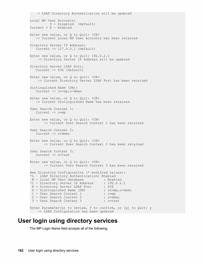
> LDAP Directory Authentication will be updated
Local MP User Accounts: D - Disabled (default)Current > E - Enabled
Enter new value, or Q to Quit: <CR> -> Current Local MP User Accounts has been retained
Directory Server IP Address: Current -> 127.0.0.1 (default)
Enter new value, or Q to Quit: 192.0.2.1 -> Directory Server IP Address will be updated
Directory Server LDAP Port: Current -> 636 (default)
Enter new value, or Q to Quit: <CR> -> Current Directory Server LDAP Port has been retained
Distinguished Name (DN): Current -> cn=mp,o=demo
Enter new value, or Q to Quit: <CR> -> Current Distinguished Name has been retained
User Search Context 1: Current -> o=mp
Enter new value, or Q to Quit: <CR> -> Current User Search Context 1 has been retained
User Search Context 2: Current -> o=demo
Enter new value, or Q to Quit: <CR> -> Current User Search Context 2 has been retained
User Search Context 3: Current -> o=test
Enter new value, or Q to Quit: <CR> -> Current User Search Context 3 has been retained
New Directory Configuration (* modified values):*L – LDAP Directory Authentication: Enabled M – Local MP User database : Enabled*I - Directory Server IP Address : 192.0.2.1 P - Directory Server LDAP Port : 636 D - Distinguished Name (DN) : cn=mp,o=demo 1 - User Search Context 1 : o=mp 2 - User Search Context 2 : o=demo 3 - User Search Context 3 : o=test
Enter Parameter(s) to revise, Y to confirm, or [Q] to Quit: y -> LDAP Configuration has been updated
User login using directory servicesThe MP Login Name field accepts all of the following:
162 User login using directory services

• Directory users• LDAP Fully Distinguished Names
Example: CN=John Smith,CN=Users,DC=HP,DC=COM, or @HP.com
The short form of the login name by itself does not identify which domain you are trying to access. Toidentify the domain, provide the domain name or use the LDAP Distinguished Name of your account.
• Domain\user name form (Active Directory only)
Example: HP\jsmith• username@domain form (Active Directory only)
Directory users that are specified with the @ searchable form can be located in one of threesearchable contexts that are configured within Directory Settings.
Example: [email protected]• User name form
Example: John Smith
Directory users that are specified with the user name form can be located in one of three searchablecontexts that are configured within Directory Settings.
• Local users - Login ID
For the iLO 3 login, the maximum length of the Login Name is 25 characters for local users. Fordirectory services users, the maximum length of the Login Name is 256 characters.
Certificate servicesThe following sections provide instructions for installing Certificate Services, verifying directory services,and configuring automatic certificate requests.
Installing certificate servicesTo install certificate services:
Procedure
1. Select Start>Settings>Control Panel.2. Double-click Add/Remove Programs.3. Click Add/Remove Windows Components to start the Windows Components wizard.4. Select Certificate Services and click Next.5. At the warning that the server cannot be renamed, click OK. The Enterprise root CA option is selected
because there is no CA registered in the Active Directory.6. Enter the information appropriate for your site and organization. Accept the default time period of two
years in the Valid for field and click Next.7. Accept the default locations of the certificate database and the database log. Click Next.8. Browse to the c:∖I386 folder when prompted for the Windows 2000 Advanced Server CD.9. Click Finish to close the wizard.
Verifying directory servicesBecause iLO 3 communicates with Active Directory using SSL, you must create a certificate or installCertificate Services. Install an enterprise CA because you are issuing certificates to objects within yourorganizational domain.
To verify that certificate services is installed, select Start>Programs>AdministrativeTools>Certification Authority. If Certificate Services is not installed, an error message appears.
Certificate services 163

Configuring an automatic certificate requestTo request that a certificate be issued to the server:
Procedure
1. Select Start>Run, and enter mmc.2. Click Add.3. Select Group Policy, and click Add to add the snap-in to the MMC.4. Click Browse, and select the Default Domain Policy object. Click OK.5. Select Finish>Close>OK.6. Expand Computer Configuration>Windows Settings>Security Settings>Public Key Policies.7. Right-click Automatic Certificate Requests Settings, and select New>Automatic Certificate
Request.8. When the Automatic Certificate Request Setup wizard starts, click Next.9. Select the Domain Controller template, and click Next.10. Select the certificate authority listed. (the same CA defined during the Certificate Services
installation). Click Next.11. Click Finish to close the wizard.
Directory-enabled remote managementThis section is for administrators who are familiar with directory services and with the iLO 3 product. Tofamiliarize yourself with the product and services, see Directory services on page 135. Be sure youunderstand the examples and are comfortable with setting up the product.
In general, you can use the HP provided snap-ins to create objects. It is useful to give the iLO 3 deviceobjects meaningful names, such as the device network address, DNS name, host server name, or serialnumber.
Directory-enabled remote management enables you to:
• Create iLO 3 objects:
Each device object created represents each device that will use the directory service to authenticateand authorize users. For more information, see the following sections:
Directory services for Active Directory on page 140
Directory services for eDirectory on page 152• Configure iLO 3 devices:
Every iLO 3 device that uses the directory service to authenticate and authorize users must beconfigured with the appropriate directory settings. For details about the specific directory settings, see Using the LDAP command to configure directory settings on page 161. In general, each device isconfigured with the appropriate directory server address, iLO 3 object distinguished name, and anyuser contexts. The server address is either the IP address or DNS name of a local directory server, or,for more redundancy, a multihost DNS name.
Using existing groupsMany organizations arrange users and administrators into groups. In many cases, it is convenient to useexisting groups and associate these groups with one or more iLO 3 role objects. When the devices areassociated with role objects, you can control access to the iLO 3 devices associated with the role byadding or deleting members from the groups.
When using Microsoft Active Directory, you can place one group within another, or create nested groups.Role objects are considered groups and can include other groups directly. To include other groups
164 Configuring an automatic certificate request

directly, add the existing nested group directly to the role and assign the appropriate rights andrestrictions. Add new users to either the existing group or to the role.
Novell® eDirectory does not allow nested groups. In eDirectory, any user who can read a role isconsidered a member of that role. When adding an existing group, organizational unit, or organization toa role, add the object as a read trustee of the role. All the members of the object are considered membersof the role. Add new users to either the existing object or to the role.
When you use trustee or directory rights assignments to extend role membership, users must be able toread the iLO 3 object representing the iLO 3 device. Some environments require the trustees of a role toalso be read trustees of the iLO 3 object to successfully authenticate users.
Using multiple rolesMost deployments do not require that the same user be in multiple roles managing the same device.However, these configurations are useful for building complex rights relationships. When buildingmultiple-role relationships, users receive all the rights assigned by every applicable role. Roles only grantrights, not revoke them. If one role grants a user a right, the user has the right, even if the user is inanother role that does not grant that right.
Typically, a directory administrator creates a base role with the minimum number of rights assigned andthen creates additional roles to add additional rights. These additional rights are added under specificcircumstances or to a specific subset of the base role users.
For example, an organization might have two types of users: administrators of the iLO 3 device or hostserver, and users of the iLO 3 device. In this situation, it makes sense to create two roles, one for theadministrators and one for the users. Both roles include some of the same devices, but grant differentrights. Sometimes, it is useful to assign generic rights to the lesser role, and include the iLO 3administrators in that role, and the administrative role.
Figure 67: Admin user gaining admin role right, example 1 on page 165 shows one way that anadministrative user gains admin role right. The admin user’s initial login right is granted through theregular user role. After the initial login, more advanced rights are assigned to the admin user through theadmin role such as server reset and remote console.
Figure 67: Admin user gaining admin role right, example 1
In Figure 68: Admin user gaining admin role right, example 2 on page 166, the admin user gains theadmin role right in a different way. The admin user initially logs in through the admin role and isimmediately assigned admin rights (server reset, remote console, and login).
Using multiple roles 165

Figure 68: Admin user gaining admin role right, example 2
Creating roles that follow organizational structureOften, administrators within an organization are placed into a hierarchy in which subordinateadministrators must assign rights independently of ranking administrators. In this case, it is useful to haveone role that represents the rights assigned by higher-level administrators, and to enable subordinateadministrators to create and manage their own roles.
Restricting rolesRestrictions enable you to limit the scope of a role. A role only grants rights to those users who satisfy therole restrictions. Using restricted roles creates users with dynamic rights that change based on the time ofday or network address of the client.
For step-by-step instructions on how to create network and time restrictions for a role, see Setting rolerestrictions on page 157 or Setting time restrictions on page 157.
Role time restrictionsYou can place time restrictions on iLO 3 roles. Users are only granted rights that are specified for the iLO3 devices listed in the role if they are members of the role and meet the time restrictions for that role.
The iLO 3 devices use local host time to enforce time restrictions. If the iLO 3 device clock is not set, therole time restriction fails (unless no time restrictions are specified on the role).
Role-based time restrictions can only be enforced if the time is set on the iLO 3 device. The time isnormally set when the host is booted and is maintained by running the agents in the host operatingsystem, which enables iLO 3 device to compensate for leap years and minimize clock drift with respect tothe host. Events such as unexpected power loss or the flashing of MP firmware can cause the iLO 3device clock not to be set. Also, the host time must be correct for the iLO 3 device to preserve time acrossfirmware flashes.
IP address range restrictionsIP address range restrictions enable you to specify network addresses that are granted or denied accessby the restriction. The address range is typically specified in a low-to-high range format. You can specifyan address range to grant or deny access to a single address. Addresses that fall within the low-to-highIP address range meet the IP address restriction.
IP address and subnet mask restrictionsIP address and subnet mask restrictions enable you to specify a range of addresses that are granted ordenied access by the restriction. This format has similar capabilities to those in an IP address range butcan be more native to your networking environment. An IP address and subnet mask range is typicallyspecified using a subnet address and address bit mask that identifies addresses on the same logicalnetwork.
166 Creating roles that follow organizational structure

In binary math, if the bits of a client machine address are added to the bits of the subnet mask, and thesebits match the restriction subnet address, the client machine meets the restriction.
DNS-based restrictionsDNS-based restrictions use the network naming service to examine the logical name of the clientmachine by looking up machine names assigned to the client IP addresses. DNS restrictions require afunctional name server. If the name service fails or cannot be reached, DNS restrictions cannot bematched and will fail.
DNS-based restrictions can limit access to a single, specific machine name or to machines sharing acommon domain suffix. For example, the DNS restriction www.hp.com matches hosts that are assignedthe domain name www.hp.com. However, the DNS restriction *.hp.com matches any machineoriginating from HP.
DNS restrictions can cause some ambiguity because a host can be multi-homed. DNS restrictions do notnecessarily match one-to-one with a single system.
CAUTION:
Using DNS-based restrictions can create some security complications. Name service protocols areinsecure. Any individual with malicious intent and access to the network can place a rogue DNSservice on the network, creating fake address restriction criteria. When implementing DNS-basedaddress restrictions, take organizational security policies into consideration.
Role address restrictionsRole address restrictions are enforced by the MP firmware, based on the client IP network address. Whenthe address restrictions are met for a role, the rights granted by the role apply.
Address restrictions can be difficult to manage if access is attempted across firewalls or through networkproxies. Either of these mechanisms can change the apparent network address of the client, causing theaddress restrictions to be enforced in an unexpected manner.
Enforcing directory login restrictionsFigure 69: User and role access restrictions on page 168 shows how two sets of restrictionspotentially limit a directory user's access to iLO 3 devices. User access restrictions limit a user's access toauthenticate to the directory. Role access restrictions limit an authenticated user's ability to receive iLO 3privileges based on rights specified in one or more roles.
DNS-based restrictions 167

Figure 69: User and role access restrictions
Enforcing user time restrictionsYou can place a time restriction on directory user accounts. Time restrictions limit the ability of the user tolog in (authenticate) to the directory. Typically, time restrictions are enforced using the time on thedirectory server, but if the directory server is located in a different time zones or a replica in a differenttime zone is accessed, time zone information from the managed object can be used to adjust for relativetime.
While directory server evaluates user time restrictions, the determination can be complicated by timezone changes or by the authentication mechanism.
Figure 70: User time restrictions on page 168 shows the user time restrictions.
Figure 70: User time restrictions
168 Enforcing user time restrictions

User address restrictionsYou can place network address restrictions on a directory user account, and the directory server enforcesthese restrictions. For information about the enforcement of address restrictions on LDAP clients, such asa user logging in to an iLO 3 device, see the directory service documentation.
Network address restrictions placed on the user in the directory may not be enforced in the expectedmanner if the directory user logs in through a proxy server. When a user logs in to an iLO 3 device as adirectory user, the iLO 3 device attempts authentication to the directory as that user, which means thataddress restrictions placed on the user account apply when accessing the iLO 3 device. However,because the user is proxied at the iLO 3 device, the network address of the authentication attempt is thatof the iLO 3 device, not that of the client workstation.
Creating multiple restrictions and rolesThe most useful application of multiple roles includes restricting one or more roles so that rights do notapply in all situations. Other roles provide different rights under different constraints. Using multiplerestrictions and roles enables you to create arbitrary, complex rights relationships with a minimum numberof roles.
For example, an organization might have a security policy in which iLO 3 administrators are allowed touse the iLO 3 device from within the corporate network but are only able to reset the server outside ofregular business hours.
Directory administrators may be tempted to create two roles to address this situation, but extra caution isrequired. Creating a role that provides the required server reset rights and restricting it to an after-hoursapplication might allow administrators outside the corporate network to reset the server, which is contraryto most security policies.
Figure 71: Restricting general use on page 169 shows how security policy dictates that general use isrestricted to clients within the corporate subnet, and server reset capability is additionally restricted toafter hours.
Figure 71: Restricting general use
Alternatively, the directory administrator can create a role that grants the login right and restrict it to thecorporate network, create another role that grants only the server reset right and restrict it to after-hoursoperation. This configuration is easier to manage but more unsecure because ongoing administration cancreate another role that grants users from addresses outside the corporate network the login right, whichmight unintentionally grant the iLO 3 administrators in the server reset role the ability to reset the serverfrom anywhere, provided they satisfy the time constraints of that role.
User address restrictions 169

CAUTION:
The previous configuration satisfies corporate security policy. However, adding another role thatgrants the login right can inadvertently grant server reset privileges from outside the corporatesubnet after hours. A more manageable solution might be to restrict the reset role, as well as thegeneral use role.
Figure 72: Restricting the reset role
Directory services schema (LDAP)A directory schema specifies the types of objects that a directory can have and the mandatory andoptional attributes of each object type. The following sections describe both the HP management core,and the LDAP object identifier classes and attributes that are specific to iLO 3.
HP management core LDAP object identifier classes and attributesObject identifiers (OIDs) are unique numbers that are used by LDAP to identify object class, attribute,syntaxes (data types), matching rules, protocol mechanisms, controls, extended operation and supportedfeatures.
Changes made to the schema during the schema setup process include changes to the following:
• Core classes• Core attributes
NOTE:
Roles such as hpqTargets, and so on, are for extended schema LDAP only. They are not used inschema-free LDAP.
170 Directory services schema (LDAP)

Core LDAP OID classes
Table 38: Core classes
Class Name Assigned OID
hpqTarget 1.3.6.1.4.1.232.1001.1.1.1.1
hpqRole 1.3.6.1.4.1.232.1001.1.1.1.2
hpqPolicy 1.3.6.1.4.1.232.1001.1.1.1.3
Core LDAP OID attributes
Table 39: Core attributes
Attribute Name Assigned OID
hpqPolicyDN 1.3.6.1.4.1.232.1001.1.1.2.1
hpqRoleMembership 1.3.6.1.4.1.232.1001.1.1.2.2
hpqTargetMembership 1.3.6.1.4.1.232.1001.1.1.2.3
hpqRoleIPRestrictionDefault 1.3.6.1.4.1.232.1001.1.1.2.4
hpqRoleIPRestrictions 1.3.6.1.4.1.232.1001.1.1.2.5
hpqRoleTimeRestriction 1.3.6.1.4.1.232.1001.1.1.2.6
Core class definitionsTable 40, Table 41, and Table 42 define the HP management core classes.
hpqTarget
Table 40: hpqTarget
OID 1.3.6.1.4.1.232.1001.1.1.1.1
Description This class defines target objects, providing the basis for HP products usingdirectory-enabled management.
Class Type Structural
SuperClasses User
Attributes hpqPolicyDN—1.3.6.1.4.1.232.1001.1.1.2.1hpqRoleMembership—1.3.6.1.4.1.232.1001.1.1.2.2
Remarks None
Core LDAP OID classes 171
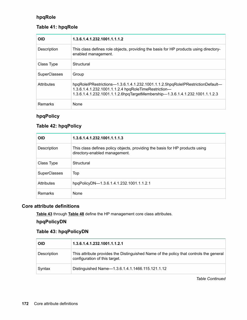
hpqRole
Table 41: hpqRole
OID 1.3.6.1.4.1.232.1001.1.1.1.2
Description This class defines role objects, providing the basis for HP products using directory-enabled management.
Class Type Structural
SuperClasses Group
Attributes hpqRoleIPRestrictions—1.3.6.1.4.1.232.1001.1.1.2.5hpqRoleIPRestrictionDefault—1.3.6.1.4.1.232.1001.1.1.2.4 hpqRoleTimeRestriction—1.3.6.1.4.1.232.1001.1.1.2.6hpqTargetMembership—1.3.6.1.4.1.232.1001.1.1.2.3
Remarks None
hpqPolicy
Table 42: hpqPolicy
OID 1.3.6.1.4.1.232.1001.1.1.1.3
Description This class defines policy objects, providing the basis for HP products usingdirectory-enabled management.
Class Type Structural
SuperClasses Top
Attributes hpqPolicyDN—1.3.6.1.4.1.232.1001.1.1.2.1
Remarks None
Core attribute definitionsTable 43 through Table 48 define the HP management core class attributes.
hpqPolicyDN
Table 43: hpqPolicyDN
OID 1.3.6.1.4.1.232.1001.1.1.2.1
Description This attribute provides the Distinguished Name of the policy that controls the generalconfiguration of this target.
Syntax Distinguished Name—1.3.6.1.4.1.1466.115.121.1.12
Table Continued
172 Core attribute definitions

OID 1.3.6.1.4.1.232.1001.1.1.2.1
Options Single Valued
Remarks None
hpqRoleMembership
Table 44: hpqRoleMembership
OID 1.3.6.1.4.1.232.1001.1.1.2.2
Description This attribute provides a list of hpqTarget objects to which this object belongs.
Syntax Distinguished Name—1.3.6.1.4.1.1466.115.121.1.12
Options Multi Valued
Remarks None
hpqTargetMembership
Table 45: hpqTargetMembership
OID 1.3.6.1.4.1.232.1001.1.1.2.3
Description This attribute provides a list of hpqTarget objects that belong to this object.
Syntax Distinguished Name—1.3.6.1.4.1.1466.115.121.1.12
Options Multi Valued
Remarks None
hpqRoleIPRestrictionDefault
Table 46: hpqRoleIPRestrictionDefault
OID 1.3.6.1.4.1.232.1001.1.1.2.4
Description This attribute is a Boolean expression representing access by unspecified clients,which partially specifies rights restrictions under an IP network address constraint.
Syntax Boolean—1.3.6.1.4.1.1466.115.121.1.7
Options Single Valued
Remarks If this attribute is TRUE, IP restrictions are satisfied for unexceptional networkclients. If this attribute is FALSE, IP restrictions are unsatisfied for unexceptionalnetwork clients.
Installing and configuring directory services 173

hpqRoleIPRestrictions
Table 47: hpqRoleIPRestrictions
OID 1.3.6.1.4.1.232.1001.1.1.2.5
Description This attribute provides a list of IP addresses, DNS names, domain, address ranges,and subnets, which partially specify right restrictions under an IP network addressconstraint.
Syntax Octet String-1.3.6.1.4.1.1466.115.121.1.40
Options Multi Valued
Remarks This attribute is only used on role objects. The IP restrictions are satisfied when theaddress matches and general access is denied, and unsatisfied when the addressmatches and general access is allowed. Values are an identifier byte followed by atype-specific number of bytes specifying a network address. For IP subnets, theidentifier is <0x01>, followed by the IP network address in network order, followed bythe IP network subnet mask in network order. For example, the IP subnet127.0.0.1/255.0.0.0 can be represented as <0x01 0x7F 0x00 0x00 0x01 0xFF 0x000x00 0x00>. For IP ranges, the identifier is <0x02>, followed by the lower bound IPaddress, followed by the upper bound IP address. Both are inclusive and in networkorder. For example, the IP range 10.0.0.1 to 10.0.10.255 is represented as <0x020x0A 0x00 0x00 0x01 0x0A 0x00 0x0A 0xFF>. For DNS names or domains, theidentifier is <0x03>, followed by the ASCII encoded DNS name. DNS names can beprefixed with a * (ASCII 0x2A), to indicate they match names that end with thespecified string. For example, match the DNS domain *.acme.com is representedas <0x03 0x2A 0x2E 0x61 0x63 0x6D 0x65 0x2E 0x63 0x6F 0x6D>. General accessis allowed.
hpqRoleTimeRestriction
Table 48: hpqRoleTimeRestriction
OID 1.3.6.1.4.1.232.1001.1.1.2.6
Description This attribute represents a 7-day time grid, with 30-minute resolution, whichspecifies rights restrictions under a time constraint.
Syntax Octet String {42}-1.3.6.1.4.1.1466.115.121.1.40
Options Single Valued
Remarks This attribute is only used on role objects. Time restrictions are satisfied when the bitcorresponding to the current local side real-time of the device is 1, and unsatisfiedwhen the bit is 0. The least significant bit of the first byte corresponds to Sunday,from 12 midnight, to Sunday 12:30 AM. Each more significant bit and sequentialbyte corresponds to the next consecutive half-hour blocks within the week. The mostsignificant (8th) bit of the 42nd byte corresponds to Saturday at 11:30 PM, to Sundayat 12 midnight.
174 Installing and configuring directory services

iLO 3-secific LDAP OID classes and attributesThe schema attributes and classes in Table 49 and Table 50 might depend on attributes or classesdefined in the HP management core classes and attributes.
iLO 3 classes
Table 49: iLO 3 classes
Class Name Assigned OID
hpqLOMv100 1.3.6.1.4.1.232.1001.1.8.1.1
iLO 3 attributes
Table 50: iLO 3 attributes
Class Name Assigned OID
hpqLOMRightLogin 1.3.6.1.4.1.232.1001.1.8.2.1
hpqLOMRightRemoteConsole 1.3.6.1.4.1.232.1001.1.8.2.2
hpqLOMRightVirtualMedia 1.3.6.1.4.1.232.1001.1.8.2.3
hpqLOMRightServerReset 1.3.6.1.4.1.232.1001.1.8.2.4
hpqLOMRightLocalUserAdmin 1.3.6.1.4.1.232.1001.1.8.2.5
hpqLOMRightConfigureSettings 1.3.6.1.4.1.232.1001.1.8.2.6
iLO 3 class definitionshpqLOMv100
Table 51: hpqLOMv100
OID 1.3.6.1.4.1.232.1001.1.8.1.1
Description This class defines the rights and settings used with HPE iLO 3 products.
Class Type Auxiliary
SuperClasses None
Table Continued
iLO 3-secific LDAP OID classes and attributes 175

OID 1.3.6.1.4.1.232.1001.1.8.1.1
Attributes hpqLOMRightConfigureSettings-1.3.6.1.4.1.232.1001.1.8.2.1
hpqLOMRightLocalUserAdmin-1.3.6.1.4.1.232.1001.1. 8.2.2
hpqLOMRightLogin-1.3.6.1.4.1.232.1001.1.8.2.3
hpqLOMRightRemoteConsole-1.3.6.1.4.1.232.1001.1.8.2.4
hpq LOMRightServerReset-1.3.6.1.4.1.232.1001.1.8.2.5
hpqLOMRightVirtualMedia-1.3.6.1.4.1.232.1001.1.8.2.6
Remarks None
iLO 3 attribute definitionsTable 52 through Table 57 define the iLO 3 core class attributes.
hpqLOMRightLogin
Table 52: hpqLOMRightLogin
OID 1.3.6.1.4.1.232.1001.1.8.2.1
Description Login right for HPE iLO 3 products.
Syntax Boolean-1.3.6.1.4.1.1466.115.121.1.7
Options Single Valued
Remarks The attribute is meaningful only on role objects. If TRUE, members of the role aregranted the right.
hpqLOMRightRemoteConsole
Table 53: hpqLOMRightRemoteConsole
OID 1.3.6.1.4.1.232.1001.1.8.2.2
Description Remote console right for iLO 3 products. Meaningful only on role objects.
Syntax Boolean-1.3.6.1.4.1.1466.115.121.1.7
Options Single valued
Remarks This attribute is only used on role objects. If this attribute is TRUE, members of therole are granted the right.
176 iLO 3 attribute definitions

hpqLOMRightRemoteConsole
Table 54: hpqLOMRightRemoteConsole
OID 1.3.6.1.4.1.232.1001.1.8.2.3
Description Virtual Media right for HPE iLO 3 products.
Syntax Boolean-1.3.6.1.4.1.1466.115.121.1.7
Options Single valued
Remarks This attribute is only used on role objects. If this attribute is TRUE, members of therole are granted the right.
hpqLOMRightServerReset
Table 55: hpqLOMRightServerReset
OID 1.3.6.1.4.1.232.1001.1.8.2.4
Description Remote server reset and power button right for HPE iLO 3 products.
Syntax Boolean-1.3.6.1.4.1.1466.115.121.1.7
Options Single valued
Remarks This attribute is only used on role objects. If this attribute is TRUE, members of therole are granted the right.
hpqLOMRightLocalUserAdmin
Table 56: hpqLOMRightLocalUserAdmin
OID 1.3.6.1.4.1.232.1001.1.8.2.5
Description Local user database administration right for HPE iLO 3 products.
Syntax Boolean-1.3.6.1.4.1.1466.115.121.1.7
Options Single valued
Remarks This attribute is only used on role objects. If this attribute is TRUE, members of therole are granted the right.
Installing and configuring directory services 177

hpqLOMRightConfigureSettings
Table 57: hpqLOMRightConfigureSettings
OID 1.3.6.1.4.1.232.1001.1.8.2.6
Description Configure devices settings right for HPE iLO 3 products.
Syntax Boolean-1.3.6.1.4.1.1466.115.121.1.7
Options Single valued
Remarks This attribute is only used on role objects. If this attribute is TRUE, members of therole are granted the right.
178 Installing and configuring directory services

Support and other resources
Accessing Hewlett Packard Enterprise Support• For live assistance, go to the Contact Hewlett Packard Enterprise Worldwide website:
http://www.hpe.com/assistance• To access documentation and support services, go to the Hewlett Packard Enterprise Support Center
website:
http://www.hpe.com/support/hpesc
Information to collect
• Technical support registration number (if applicable)• Product name, model or version, and serial number• Operating system name and version• Firmware version• Error messages• Product-specific reports and logs• Add-on products or components• Third-party products or components
Accessing updates• Some software products provide a mechanism for accessing software updates through the product
interface. Review your product documentation to identify the recommended software update method.• To download product updates:
Hewlett Packard Enterprise Support Centerwww.hpe.com/support/hpesc
Hewlett Packard Enterprise Support Center: Software downloadswww.hpe.com/support/downloads
Software Depotwww.hpe.com/support/softwaredepot
• To subscribe to eNewsletters and alerts:
www.hpe.com/support/e-updates• To view and update your entitlements, and to link your contracts and warranties with your profile, go to
the Hewlett Packard Enterprise Support Center More Information on Access to Support Materialspage:
www.hpe.com/support/AccessToSupportMaterials
IMPORTANT:
Access to some updates might require product entitlement when accessed through the HewlettPackard Enterprise Support Center. You must have an HPE Passport set up with relevantentitlements.
Support and other resources 179

Customer self repairHewlett Packard Enterprise customer self repair (CSR) programs allow you to repair your product. If aCSR part needs to be replaced, it will be shipped directly to you so that you can install it at yourconvenience. Some parts do not qualify for CSR. Your Hewlett Packard Enterprise authorized serviceprovider will determine whether a repair can be accomplished by CSR.
For more information about CSR, contact your local service provider or go to the CSR website:
http://www.hpe.com/support/selfrepair
Remote supportRemote support is available with supported devices as part of your warranty or contractual supportagreement. It provides intelligent event diagnosis, and automatic, secure submission of hardware eventnotifications to Hewlett Packard Enterprise, which will initiate a fast and accurate resolution based on yourproduct's service level. Hewlett Packard Enterprise strongly recommends that you register your device forremote support.
If your product includes additional remote support details, use search to locate that information.
Remote support and Proactive Care informationHPE Get Connected
www.hpe.com/services/getconnectedHPE Proactive Care services
www.hpe.com/services/proactivecareHPE Proactive Care service: Supported products list
www.hpe.com/services/proactivecaresupportedproductsHPE Proactive Care advanced service: Supported products list
www.hpe.com/services/proactivecareadvancedsupportedproducts
Proactive Care customer informationProactive Care central
www.hpe.com/services/proactivecarecentralProactive Care service activation
www.hpe.com/services/proactivecarecentralgetstarted
Warranty informationTo view the warranty for your product or to view the Safety and Compliance Information for Server,Storage, Power, Networking, and Rack Products reference document, go to the Enterprise Safety andCompliance website:
www.hpe.com/support/Safety-Compliance-EnterpriseProducts
Additional warranty informationHPE ProLiant and x86 Servers and Options
www.hpe.com/support/ProLiantServers-WarrantiesHPE Enterprise Servers
www.hpe.com/support/EnterpriseServers-WarrantiesHPE Storage Products
www.hpe.com/support/Storage-Warranties
180 Customer self repair

HPE Networking Productswww.hpe.com/support/Networking-Warranties
Regulatory informationTo view the regulatory information for your product, view the Safety and Compliance Information forServer, Storage, Power, Networking, and Rack Products, available at the Hewlett Packard EnterpriseSupport Center:
www.hpe.com/support/Safety-Compliance-EnterpriseProducts
Additional regulatory information
Hewlett Packard Enterprise is committed to providing our customers with information about the chemicalsubstances in our products as needed to comply with legal requirements such as REACH (Regulation ECNo 1907/2006 of the European Parliament and the Council). A chemical information report for this productcan be found at:
www.hpe.com/info/reach
For Hewlett Packard Enterprise product environmental and safety information and compliance data,including RoHS and REACH, see:
www.hpe.com/info/ecodata
For Hewlett Packard Enterprise environmental information, including company programs, productrecycling, and energy efficiency, see:
www.hpe.com/info/environment
Documentation feedbackHewlett Packard Enterprise is committed to providing documentation that meets your needs. To help usimprove the documentation, send any errors, suggestions, or comments to Documentation Feedback([email protected]). When submitting your feedback, include the document title, part number,edition, and publication date located on the front cover of the document. For online help content, includethe product name, product version, help edition, and publication date located on the legal notices page.
Regulatory information 181

Standard terms, abbreviations, and acronyms
3DES
Triple Data Encryption Algorithm
Aaddress
In networking, a unique code that identifies a node in the network. Names such as host1.hp.com aretranslated to dott-quad addresses such as 168.124.3.4 by the Domain Name Service (DNS).
address path
An address path is one in which each term has the appropriate intervening addressing association.
administrator
A person managing a system through interaction with management clients, transport clients, andother policies and procedures.
AES
Advanced Encryption Standard. This is a specification for the encryption of electronic dataestablished by the U.S. National Institute of Standards and Technology (NIST).
authentication
The process that verifies the identity of a user in a communication session, or a device or other entityin a computer system, before that user, device, or other entity can access system resources. Sessionauthentication can work in two directions: a server authenticates a client to make access controldecisions, and the client can also authenticate the server. With Secure Sockets Layer (SSL), the clientalways authenticates the server.
authorization
The process of granting specific access privileges to a user. Authorization is based on authenticationand access control.
Bbind
In the Lightweight Directory Access Protocol (LDAP), refers to the authentication process that LDAPrequires when users access the LDAP directory. Authentication occurs when the LDAP client binds tothe LDAP server.
BIOS
Basic Input/Output System. System software that controls the loading of the operating system andtesting of hardware when the system is powered on. The BIOS is stored in read-only memory (ROM).
BMC
Baseboard Management Controller. A device used to manage chassis environmental, configuration,and service functions, and receive event data from other parts of the system. It receives data throughsensor interfaces and interprets this data by using the sensor data record (SDR) for which it providesan interface. The BMC also provides an interface to the SEL. Typical functions of the BMC are
182 Standard terms, abbreviations, and acronyms

measuring processor temperature, power supply values, and cooling fan status. The BMC can takeautonomous action to preserve system integrity.
CCIM
See Common Information Model.
Cipher
In cryptography, a cipher (or cypher) is an algorithm for performing encryption or decryption.
Command Line Interface (CLI)
A text user interface (TUI) for interacting with a computer operating system or software by typingcommands at a command prompt to perform specific tasks.
Common Information Model (CIM)
An industry standard that was developed by the DMTF. CIM describes data about applications anddevices so that administrators and software management programs can control applications anddevices on different platforms in the same way, ensuring interoperability across a network.
CIM provides a common definition of management information for systems, components, networks,applications, and services, and it allows for vendor extensions. CIM common definitions enablevendors to exchange management information between systems.
Using techniques of object-oriented programming, CIM provides a consistent definition and structureof data, including expressions for elements such as object classes, properties, associations, andmethods.
For example, if an enterprise purchases four different servers from four different vendors andnetworks them together, using CIM, the administrator can view the same information about each ofthe devices, such as manufacturer and serial number, the device’s model number, its location on thenetwork, its storage capacity, and its relationship to the applications that run throughout the network.
console
The interface between iLO 3 and the server that controls basic functionality. Also known as hostconsole.
DDDNS
Dynamic Domain Name System. DDNS is how iLO 3 automatically registers its name with the DomainName System so that when iLO 3 receives its new IP address from DHCP, users can connect to thenew iLO 3 using the host name, rather than the new IP address.
DHCP
Dynamic Host Configuration Protocol. A protocol that enables a DHCP server to assign InternetProtocol (IP) addresses dynamically to systems on a Transmission Control Protocol/Internet Protocol(TCP/IP) network. Without DHCP, IP addresses must be entered manually at each computer, andwhen computers are moved to another location on another part of the network, a new IP addressmust be entered.
directory server
In the Lightweight Directory Access Protocol (LDAP), a server which stores and provides informationabout people and resources within an organization from a logically centralized location.
C 183
distinguished name (DN)
In the Lightweight Directory Access Protocol (LDAP), a unique text string that identifies an entry'sname and location within the directory. A DN can be a fully qualified domain name (FQDN) thatincludes the complete path from the root of the tree.
DNS
Domain Name Server. The server that typically manages host names in a domain. DNS serverstranslate host names, such as www.example.com, into Internet Protocol (IP) addresses, such as030.120.000.168.
Domain Name Service. The data query service that searches domains until a specified host name isfound.
Domain Name System. A distributed, name resolution system that enables computers to locate othercomputers on a network or the Internet by domain name. The system associates standard InternetProtocol (IP) addresses, such as 00.120.000.168, with host names, such as www.hp.com.Machines typically acquire this information from a DNS server.
domain
A grouping of hosts that is identified by a name. The hosts usually belong to the same InternetProtocol (IP) network address.
domain name
The unique name assigned to a system or group of systems on the Internet. The host names of all thesystems in the group have the same domain name suffix. Domain names are interpreted from right toleft.
EEncryption
Encryption is the process of encoding messages or information in such a way that only authorizedparties can read it.
ethernet
An industry-standard type of local area network (LAN) that enables real-time communication betweensystems connected directly through cables. Ethernet uses a Carrier Sense Multiple Access/CollisionDetection (CSMA/CD) algorithm as its access method, which all nodes listen for, and any node canbegin transmitting data. If multiple nodes attempt to transmit at the same time (a collision), thetransmitting nodes wait for a random time before attempting to transmit again.
event
A change in the state of a managed object. The event-handling subsystem can provide a notification,to which a software system must respond when it occurs, but which the software did not solicit orcontrol.
extended schema
A platform-specific schema derived from the common model. An example is the Win32 schema.
Ffirmware
Software that is typically used to help with the initial booting stage of a system and with systemmanagement. Firmware is embedded in read-only memory (ROM) or programmable ROM (PROM).
184 E

FPGA
Field Programmable Gate Array. A semiconductor device containing programmable logic componentsand programmable interconnects.
FTP
File Transfer Protocol. A basic Internet protocol based on Transmission Control Protocol/InternetProtocol (TCP/IP) that enables the retrieving and storing of files between systems on the Internetwithout regard for the operating systems or architectures of the systems involved in the file transfer.
Ggateway
A computer or program that interconnects two networks and passes data packets between thenetworks. A gateway has more than one network interface.
gateway address
Where the packet needs to be sent. This can be the local network card or a gateway (router) on thelocal subnet.
GUI
Graphical User Interface. An interface that uses graphics, along with a keyboard and mouse, toprovide easy-to-use access to an application.
Hhost
A system, such as a backend server, with an assigned Internet Protocol (IP) address and host name.The host is accessed by other remote systems on the network.
host ID
Part of the 32-bit Internet Protocol (IP) address used to identify a host on a network. Host ID is alsoknown as DNS Name or Host Name.
host console
The interface between iLO 3 and the server that controls basic functionality. Also known as console.
host name
The name of a particular machine within a domain. Host names always map to a specific InternetProtocol (IP) address.
HTTP
Hypertext Transfer Protocol. The Internet protocol that retrieves hypertext objects from remote hosts.HTTP messages consist of requests from client to server, and responses from server to client. HTTPis based on Transmission Control Protocol/Internet Protocol (TCP/IP).
Iin-band system management
A server management capability that is enabled only when the operating system is initialized and theserver is functioning properly.
G 185

Integrated Lights-Out (iLO)
The iLO functionality offers remote server management through an independent managementprocessor (MP). Integrity iLO was introduced into most HP Integrity entry class servers in late 2004.Prior to that, embedded remote server management was referred to as MP functionality. All legacyMP functionality has been carried forward and combined with new features, all under the heading of"iLO". Therefore, "iLO" and "MP" mean the same thing for entry class servers.
IP
Internet Protocol. IP specifies the format of packets and the packet addressing scheme. Mostnetworks combine IP with a higher-level protocol called Transmission Control Protocol (TCP), whichestablishes a virtual connection between a destination and a source. TCP/IP establishes a connectionbetween two hosts so that they can send messages back and forth for a period of time. The format ofan IP address is a 32-bit numeric address written as four numbers separated by periods. Eachnumber can be zero to 255; for example, 1.160.10.240. Within an isolated network, you can assign IPaddresses at random as long as each one is unique. However, connecting a private network to theInternet requires using registered IP addresses (called Internet addresses) to avoid duplicates.
IP Address
An identifier for a computer or device on a TCP/IP network.
IPMI
Intelligent Platform Management Interface. A hardware-level interface specification designed primarilyfor the out-of-band management of server systems over a number of different physical interconnects.The IPMI specification describes extensive abstractions regarding sensors, enabling a managementapplication running on the operating system or in a remote system to comprehend the environmentalmakeup of the system and to register with the IPMI subsystem to receive events. IPMI is compatiblewith management software from heterogeneous vendors. IPMI functionality includes inventoryreporting, system monitoring, logging, system recovery (including local and remote system resets,and power on and power off capabilities), and alerting.
Kkernel
The core of the operating system that manages the hardware and provides fundamental services thatthe hardware does not provide, such as filing and resource allocation.
KVM switch
Keyboard, Video, Mouse. A hardware device that allows a user, or multiple users, to control multiplecomputers from a single keyboard, video monitor and mouse.
LLDAP
Lightweight Directory Access Protocol. A directory service protocol used for the storage, retrieval, anddistribution of information, including user profiles, distribution lists, and configuration data. LDAP runsover Transmission Control Protocol/Internet Protocol (TCP/IP) across multiple platforms.
MMedia Access Control (MAC)
Worldwide unique, 48-bit, hardware address number that is programmed in to each local areanetwork interface card (NIC) at the time of manufacture. In the Ethernet standard, every networkconnection must support a unique MAC value.
186 K

MAP
Manageability Access Point. A network-accessible interface for managing a computer system. A MAPcan be initiated by a management process, a management processor, a service processor, or aservice process.
MAP address space
This is the hierarchical graph of the UFiTs contained in the MAP’s AdminDomain. Each instancestarting at the AdminDomain is a node in the graph. Each supported association forms a link in thegraph to another instance node, and so on, until a terminating instance node is encountered.
managed object
The actual item in the system environment that is accessed by the provider. For example, a NetworkInterface Card (NIC).
Management Information Base (MIB)
The MIB defines the properties of the managed object within the device to be managed. Everymanaged device keeps a database of values for each definition written in the MIB. MIB is not theactual database itself and is implementation dependant.
Management Processor (MP)
The component that provides a LAN interface to the system console and system management. Priorto iLO 3, embedded remote server management was referred to as MP functionality. All legacy MPfunctionality has been carried forward and combined with new features, all under the heading of "iLO3". Therefore, "iLO 3" and "MP" mean the same thing for entry class servers.
MFW
Manageability FirmWare.
Monarch
The monarch server blade is always in the lowest numbered enclosure bay, and all communication tothe conjoined server blade is done through the monarch server blade.
MP Upgradeability
Firmware remotely upgradeable through MP LAN, offline update through EFI, and OS-initiatedfirmware updates for all Integrity support OS.
NNetwork Interface Card (NIC)
An internal circuit board or card that connects a workstation or server to a networked device.
network mask
A number used by software to separate a local subnet address from the rest of an Internet Protocol(IP) address.
node
An addressable point or device on a network. A node can connect a computing system, a terminal, orvarious peripheral devices to the network.
OOnboard Administrator
The BladeSystem Onboard Administrator (OA) is the enclosure MP, subsystem, and firmware baseused to support HP Integrity server blades and all the managed devices contained within the
N 187

enclosure. The OA provides a single point from which to perform basic management tasks on serverblades or switches within the enclosure. Utilizing this hard-wired information, the OA performs initialconfiguration steps for the enclosure, allows for run-time management and configuration of enclosurecomponents, and informs administrators about problems within the enclosure through email or theInsight Display.
out-of-band system management
Server management capability that is enabled when the operating system network drivers or theserver are not functioning properly.
Pport
The location (socket) where Transmission Control Protocol/Internet Protocol (TCP/IP) connections aremade. Web servers traditionally use port 80, the File Transfer Protocol (FTP) uses port 21, and Telnetuses port 23. A port enables a client program to specify a particular server program in a computer ona network. When a server program is started initially, it binds to its designated port number. Any clientthat wants to use that server must send a request to bind to the designated port number.
port number
A number that specifies an individual Transmission Control Protocol/Internet Protocol (TCP/IP)application on a host machine, providing a destination for transmitted data.
POST
Power-On Self-Test. The series of steps that the host system CPU performs following power-on.Steps include testing memory, initializing peripherals, and running option ROMs. Following POST, thehost ROM passes control to the installed operating system.
properties
Properties are attributes that are relevant to a target that are passed as parameters to the command.Property keywords map to properties of CIM class.
protocol
A set of rules that describes how systems or devices on a network exchange information.
proxy
A mechanism whereby one system acts on behalf of another system in responding to protocolrequests.
Rrackmount
Electronic equipment and devices designed to fit industry-standard-sized computer racks andcabinets (19" wide). Rackmount devices are also standard 1.75 inch units.
remote system
A system other than the one on which the user is working.
Sschema
Definitions that describe what type of information can be stored as entries in the directory. Wheninformation that does not match the schema is stored in the directory, clients attempting to access the
188 P

directory may be unable to display the proper results. Schemas come in many forms, such as a textfile, information in a repository, or diagrams.
security
Secure Socket Layer Secure Shell (SSH) version 2 (Password and certificate), SSL, and integrationwith enterprise directory services.
serial console
A terminal connected to the serial port on the service processor. A serial console is used to configurethe system to perform other administrative tasks.
server blade
A single circuit board populated with components such as processors, memory, and networkconnections that are usually found on multiple boards.
SSH
Secure Shell. A UNIX shell program and network protocol that enables secure and encrypted log inand running of commands on a remote system over an insecure network.
SSL
Secure Sockets Layer. A protocol that enables client-to-server communication on a network to beencrypted for privacy. SSL uses a key exchange method to establish an environment in which all dataexchanged is encrypted with a cipher and hashed to protect it from eavesdropping and alteration.SSL creates a secure connection between a web server and a web client. Hypertext Transfer ProtocolSecure (HTTPS) uses SSL.
subnet
A working scheme that divides a single logical network into smaller physical networks to simplifyrouting. The subnet is the portion of an Internet Protocol (IP) address that identifies a block of hostIDs.
subnet mask
A bit mask used to select bits from an Internet address for subnet addressing. The mask is 32 bitslong, and selects the network portion of the Internet address and one or more bits of the local portion.Also called an address mask.
System Event Log (SEL)
A log that provides nonvolatile storage for system events that are logged autonomously by the serviceprocessor, or directly with event messages sent from the host.
Ttarget address
The target addressing scheme provides an easy-to-use method to accurately address CIM objects.The target address term of the CLP syntax in this architecture is extensible. The addressing schemeprovides a unique target for CLP commands. The scheme is finite for parsing target names, andunique for unambiguous access to associated instance information needed to support associationtraversal rooted at the MAP AdminDomain instance.
target address scheme resolution service
This entity is responsible for discovering and enumerating the managed elements within the localdomain, for maintaining the addressing and naming structure of the local domain, and coordinatingthis information with the operation invocation engine.
T 189
Telnet
A telecommunications protocol providing specifications for emulating a remote computer terminal sothat one can access a distant computer and function online using an interface that appears to be partof the user's local system.
TUI
Text User Interface. A command-line interface that enables you to enter and run commands in the MP.
UUnified Extensible Firmware Interface (UEFI)
EFI is an Itanium-based architecture feature that defines the interfaces between the operating systemand the system firmware, and between firmware driver and the system firmware. EFI provides astandard environment for booting an OS and running preboot applications. EFI post-1.10 activities isowned by the nonprofit organization named Unified EFI Forum, Inc. The Unified EFI Forum is a non-profit collaborative trade organization formed to promote and manage the UEFI standard. As anevolving standard, the UEFI specification is driven by contributions and support from membercompanies of the UEFI Forum.
Universal Serial Bus (USB)
An external bus standard that supports data transfer rates of 450 Mb/s (USB 2.0). A USB portconnects devices such as mouse pointers, keyboards, and printers, to the computer system.
user account
A record of essential user information that is stored on the system. Each user who accesses a systemhas a user account.
User Friendly Tag (UFT)
A short, user-friendly tag for a CIM class name or instance. There are two types of UFTs; UFcT andUFiT.
User Friendly class Tag (UFcT)
A short, user-friendly synonym for a CIM class name. It has the same properties and methods as theCIM class it represents.
User Friendly instance Tag (UFiT)
A unique instance tag within the scope of the target instance’s containment class. A UFiT is createdby adding an nonzero positive-integer suffix to the target instance’s UFcT.
User Friendly instance Path (UFiP)
A unique path to an instance formed by concatenating the UFiTs of each instance from the rootinstance to the terminating instance. The intervening ‘/’ between each UFiT represents an addressassociation.
user name
A combination of letters, and possibly numbers, that identifies a user to the system.
UTF-8
Unicode Transformation Format (8-bit). A variable-length character encoding for Unicode.
190 U

VVirtual Media
Also, vMedia. Connects a CD/DVD-ROM drive or CD disk image files on client system to the remoteserver so they appear local to the server during system boot or while the operating system isavailable. Supports HP-UX, Windows, and Linux server operating environments using Windows andLinux clients.
vKVM
Virtual keyboard, video, mouse.
VPN
Virtual private network. A network that is constructed using public wires (the Internet) to connectnodes. These systems use encryption and other security mechanisms to ensure only authorizedusers can access the network and that the data cannot be intercepted.
V 191