hp ilo chassis management ipmi user guide · pdf filetimestampusingtheget sdr repository info...
TRANSCRIPT

HP iLO Chassis Management IPMI UserGuide
AbstractThis document provides customers with information on the implementation of the Intelligent Platform Management Interface inHP Moonshot iLO Chassis Management Firmware, including the available commands.
HP Part Number: 742544-004Published: November 2015Edition: 2

© Copyright 2014, 2015
Notices
Confidential computer software. Valid license from HP required for possession, use, or copying. Consistent with FAR 12.211 and 12.212, CommercialComputer Software, Computer Software Documentation, and Technical Data for Commercial Items are licensed to the U.S. Government undervendor's standard commercial license.
The information contained herein is subject to change without notice. The only warranties for HP products and services are set forth in the expresswarranty statements accompanying such products and services. Nothing herein should be construed as constituting an additional warranty. HP shallnot be liable for technical or editorial errors or omissions contained herein.

Contents1 Introduction and key concepts......................................................................7
Overview................................................................................................................................7Sensor Data Model...................................................................................................................7
Sensor owner identification...................................................................................................7Sensor type code.................................................................................................................8System event log and event messages.....................................................................................8SDR repository..................................................................................................................10
SDR formats.................................................................................................................10Reading the SDR repository and device SDR repositories....................................................11
FRU......................................................................................................................................11FRU inventory device..........................................................................................................12
Standardized timers................................................................................................................12Watchdog timer................................................................................................................12POH counter.....................................................................................................................12Timestamp format...............................................................................................................12
2 The virtual topology of the Moonshot 1500 CM module................................143 Discovering managed entities using IPMITool................................................174 IPMItool..................................................................................................18
Moonshot IPMItool support — out of band.................................................................................18Interfaces...............................................................................................................................19
System Interface.................................................................................................................19LANPlus Interface...............................................................................................................19
Features................................................................................................................................20Events...................................................................................................................................21Inventory...............................................................................................................................22Chassis management..............................................................................................................22Synopsis................................................................................................................................23IPMItool Raw command syntax and example..............................................................................24
5 Command specification.............................................................................25Standard command specification..............................................................................................29
Global commands.............................................................................................................29Get device GUID..........................................................................................................29Get device ID command................................................................................................30Cold reset command ....................................................................................................33Warm reset command...................................................................................................33Get self test results command .........................................................................................33Get ACPI power state command .....................................................................................34Broadcast get device ID command .................................................................................35
IPMI messaging support commands......................................................................................36Set MC global enables command ..................................................................................36Get BMC global enables command ................................................................................37Clear message flags command ......................................................................................37Get message flags command .........................................................................................38Enable message channel receive command .....................................................................38Get message command ................................................................................................39Send message command...............................................................................................42Get system GUID command ...........................................................................................44Set system info parameters command ..............................................................................45Get system info parameters command..............................................................................46
Contents 3

Master write-read command...........................................................................................49Get channel authentication capabilities command.............................................................50Get Channel Cipher Suites Command.............................................................................52
Cipher suite records..................................................................................................54Cipher suite ID numbers............................................................................................55
Set session privilege level command ...............................................................................56Close session command.................................................................................................57Get session info command ............................................................................................57Get AuthCode command ..............................................................................................59Set channel access command ........................................................................................60Get channel access command .......................................................................................62Get channel info command ...........................................................................................63Set user access command..............................................................................................65Get user access command..............................................................................................66Set user name command ...............................................................................................68Get user name command...............................................................................................68Set user password command..........................................................................................69
RMCP+ support and payload commands..............................................................................70Activate payload command............................................................................................71Deactivate payload command........................................................................................73Suspend/resume payload encryption command................................................................74Set channel security keys command.................................................................................75Get system interface capabilities command.......................................................................77Get payload activation status command...........................................................................78Get payload instance info command...............................................................................79Set user payload access command..................................................................................79Get user payload access command.................................................................................80Get channel payload support command...........................................................................81Get channel payload version command...........................................................................82
IPMI LAN Device Commands...............................................................................................83Set LAN configuration parameters command....................................................................83Get LAN configuration parameters command...................................................................83
SOL commands.................................................................................................................92Set SOL configuration parameters command.....................................................................92Get SOL configuration parameters command....................................................................93
MC watchdog timer commands...........................................................................................96Watchdog timer actions.................................................................................................96Watchdog timer use field and expiration flags..................................................................97
Using the timer use field and expiration flags...............................................................97Watchdog timer event logging........................................................................................97Pre-timeout interrupt.......................................................................................................98
Pre-timeout interrupt support detection.........................................................................98BIOS support for watchdog timer................................................................................98
Reset watchdog timer command .....................................................................................98Set watchdog timer command ........................................................................................98Get watchdog timer command .....................................................................................100
Chassis commands..........................................................................................................102Get chassis capabilities command ................................................................................102Get chassis status command ........................................................................................103Chassis control command ............................................................................................104Chassis identify command ...........................................................................................105Set power restore policy command ...............................................................................106Set system boot options command ................................................................................107Get system boot options command................................................................................107Get POH counter command .........................................................................................111
4 Contents

Event commands..............................................................................................................112Set event receiver command.........................................................................................112Get event receiver command........................................................................................113Platform event message command.................................................................................113
SEL commands................................................................................................................114SEL device commands..................................................................................................114
Get SEL info command............................................................................................114Reserve SEL command............................................................................................115Get SEL entry command..........................................................................................116Add SEL entry command.........................................................................................116
Clear SEL...................................................................................................................117SEL record type ranges................................................................................................117Get SEL time command................................................................................................118Set SEL time command.................................................................................................118
SDR repository device commands......................................................................................118SDR record IDs...........................................................................................................118Get SDR repository info command.................................................................................119Get SDR repository allocation info command..................................................................120Reserve SDR repository command.................................................................................120
Reservation restricted commands..............................................................................121Reservation cancellation..........................................................................................121
Get SDR command......................................................................................................121Add SDR command.....................................................................................................122Delete SDR command..................................................................................................123Clear SDR repository command....................................................................................123Run initialization agent command..................................................................................124
FRU inventory device commands........................................................................................124Get FRU inventory area info command...........................................................................125
Read FRU data command........................................................................................125Write FRU data command.......................................................................................126
Sensor Device Commands.................................................................................................126Get device SDR info command.....................................................................................126Get device SDR command............................................................................................127Reserve device SDR repository command.......................................................................128Get sensor thresholds command....................................................................................128Get sensor reading command.......................................................................................129
DCMI specific commands.................................................................................................130Get DCMI capability info command..............................................................................131Get asset tag command...............................................................................................133Get DCMI sensor info command...................................................................................134Set asset tag command................................................................................................135Management controller ID string...................................................................................136Get controller ID string command..................................................................................136Set controller ID string command...................................................................................136
PICMG specific commands...............................................................................................137Get PICMG properties command..................................................................................137Get address info command..........................................................................................137FRU inventory device lock control command....................................................................138
6 IPMI Messaging and Interfaces.................................................................140System Interfaces..................................................................................................................140
Message interface description...........................................................................................141IPMI Messaging Interfaces.................................................................................................141
Network function codes.........................................................................................................141Completion codes.................................................................................................................142
Contents 5

Channel Model, Authentication, Sessions, and Users.................................................................144Channel numbers.............................................................................................................145Logical channels..............................................................................................................145Channel Privilege Levels....................................................................................................145Users & Password support.................................................................................................146IPMI sessions...................................................................................................................146Session-less connections....................................................................................................147Session inactivity timeouts.................................................................................................147
System interface messaging...................................................................................................147Bridging..............................................................................................................................148
MC LUN 10b..................................................................................................................148Send Message command with response tracking..................................................................149Bridged Request Example..................................................................................................149IPMB access via master write-read command.......................................................................151MC IPMB LUNs................................................................................................................151Sending Messages to IPMB from system software.................................................................152
Keyboard Controller Style Interface.........................................................................................153KCS Interface/MC LUNs...................................................................................................153KCS Interface-MC Request message format..........................................................................153MC-KCS Interface Response Message format.......................................................................153
LAN Interface.......................................................................................................................154Remote Management Control Protocol (RMCP).....................................................................154
RMCP port numbers....................................................................................................154RMCP Message Format................................................................................................155
Serial Over LAN (SOL)..........................................................................................................1567 Support and other resources....................................................................157
Information to collect before contacting HP...............................................................................157How to contact HP................................................................................................................157HP authorized resellers..........................................................................................................157Related information...............................................................................................................157
A Command Assignments...........................................................................159B Verbose output examples.........................................................................164Glossary..................................................................................................186Index.......................................................................................................188
6 Contents

1 Introduction and key conceptsOverview
The term Intelligent Platform Management (IPMI), refers to autonomous monitoring and recoveryfeatures implemented directly in platform management hardware and firmware. The keycharacteristic of Intelligent Platform Management is that inventory, monitoring, logging, and recoverycontrol functions are available independently of the main processors, BIOS, and operating system.Platform management functions are available even when the system is in a powered down state.IPMI capabilities are a key component in providing enterprise-class management for HA systems.Platform status information is obtained and recovery actions initiated under situations where systemmanagement software and normal “in-band” management mechanisms are unavailable.The independent monitoring, logging, and access functions available through IPMI provide a levelof manageability built-in to the platform hardware. This supports systems with no system managementsoftware available for the particular operating system, or the end-user who elects not to load orenable the system management software.
NOTE: The HP Moonshot-45G Switch Module does not support IPMI. Only the HP Moonshot iLOChassis Management Firmware supports IPMI.
Sensor Data ModelThe IPMI Sensor Model provides access to monitored information including temperatures, voltages,and fan status. Instead of providing direct access to the monitoring hardware, IPMI provides accessby abstracted sensor commands, such as the Get Sensor Reading command, implementedvia a management controller. This approach isolates software from changes in the platformmanagement hardware implementation. Sensors return analog or discrete readings and eventsare either discrete or threshold-based. Sensors are classified according to:
• Type of readings
• Type of eventsEvent types, sensor types, and monitored entities are represented using numeric codes defined inthe IPMI specification. IPMI avoids reliance on strings for management information and usingnumeric codes facilitates internationalization, automated handling by higher level software, andreduces management controller code and data space requirements.
Sensor owner identificationThe definition for the Request/Response identifier, Requester’s ID, and Responder’s ID are specificto the particular messaging interface used. However, the SDR and SEL must contain informationto identify the owner of the sensor. For management controllers, a slave address and LUN identifythe owner of a sensor on the IPMB. For system software, a software ID identifies the sensor owner.These fields are used in event messages, where events from management controllers or the IPMBare identified by an 8-bit field where the upper 7 bits represent the slave address or the systemsoftware ID. The least significant bit is 0 if the value represents a slave address and 1 if the valuerepresents a system software ID.Sensor number is not part of the sensor owner ID, but is a separate field used to identify a particularsensor associated with the sensor owner. This combination of sensor owner ID and sensor numberuniquely identify a sensor in the system.
Table 1 Sensor owner ID and sensor number field definition
System Sensor Owner IDIPMB Sensor Owner ID
system software ID (7 bits)7:1 slave address (7 bits)
Overview 7

Table 1 Sensor owner ID and sensor number field definition (continued)
System Sensor Owner IDIPMB Sensor Owner ID
0 1b (ID is a software ID)0 0b (ID is a slave address)
sensor number (8 bits, FFh = reserved)LUN (2 bits)
sensor number (1 bit, FFh = reserved)
This only appears in the system node SEL, where the it islogged by the host system
In Moonshot: IPMB address of Management ControllerZone: 20PS: 0x52, ...Chassis: 0x44Cartridge: 0x82, ...System Node: 0x72, ...
Sensor type codeEach sensor has a sensor type code and are defined in “Some Moonshot sensor type codes”(page 8). Sensor type codes are used both in SDRs and event messages. An example of a sensortype code is code 0x1, which indicates a temperature sensor.
Table 2 Some Moonshot sensor type codes
Reading type codeSensor type codeSensor type
0x10x1Temperature
0xA0x4Fan
0xB0x4Fan redundancy
0x6F0xF1PICMG IPMB0 Physical Link
0x710xC0Health LED
0x700xC0UID LED
0x6F0x8Power supply
0xB0x8Power supply redundancy
For a complete listing of sensor type codes, see the IPMI specification available at:http://www.intel.com/content/www/us/en/servers/ipmi/second-gen-interface-spec-v2.html
System event log and event messagesThe MC provides a centralized, non-volatile SEL. Having the SEL and logging functions managedby the MC helps ensure that post-mortem logging information is available should a failure occurthat disables the systems processor(s).A set of IPMI commands allows the SEL to be read and cleared, and for events to be added to theSEL. The common request message used for adding events to the SEL is an event message. Eventmessages are sent to the MC via the IPMB providing the mechanism for satellite controllers to detectevents and log them into the SEL. The controller that generates an event message to anothercontroller via IPMB is the IPMB Event Generator. The controller receiving event messages is theIPMB Event Receiver.In Moonshot, event messages are sent to the zone manager by each cartridge and chassis controller.There are two event logs, the SEL and the IML. There are OEM specific commands for obtainingand displaying these logs. For more information, see the related commands in “Commandspecification” (page 25).
8 Introduction and key concepts

Event messages are special messages sent by management controllers when they detect significantor critical system management events. This includes messages for events such as:
• temperature threshold exceeded
• voltage threshold exceeded
• power fault
The event message generator notifies the system by sending an Event Request Message tothe event receiver device.When the event receiver gets a valid event message, it sends a response message to the eventmessage generator which is typically transferred to the SEL. The event receiver does not interpretevent messages so that new event message types can be added into the system without impactingevent receiver implementation.SEL commands — The SEL is a non-volatile repository for system events and some systemconfiguration information. The SEL device access the commands sent by the SEL. Event messageswhen received by the event receiver device are written to the SEL.
Table 3 SEL event records
DescriptionFieldByte
ID used for SEL record access. The Record ID values 0000h and FFFFh have specialmeaning in the Even Access commands and must not be used as Record ID valuesfor stored SEL event records.
Record ID12
[7:0] — Record typeRecord type302h = system event recordC0h-DFh = OEM timestamped, bytes 8–16 OEM definedE0h-FFh = OEM non-timestamped, bytes 4–16 OEM defined
Time when event was logged. LS byte first.Timestamp4567
RqSA & LUN if event was generated from IPMB. Software ID if event was generatedfrom system software.
Generator ID89
Byte 1[7:1] — 7–bit I2C. Slave address, or 7–bit system software ID
[0] 0b = ID is IPMB slave address1b = System software IDByte 2[7:4] — Channel number. Channel that received the event message 0h if the eventmessage was received via the system interface, primary IPMB, or internally generatedby the MC.[3.2] — Reserved. Write as 00b.[1.0] — IPMB device LUN if byte 1 holds slave address, otherwise 00b.
Event message format version (=04h for events in this specification, 03h for IPMIv1.0 event messages).1
EvM Rev10
Sensor type code for sensor that generated the event.Sensor type11
Number of sensor that generated the event.Sensor #12
Event dirEvent dir 113[7] — 0b = Assertion event.Event type1b = Deassertion event.
Sensor Data Model 9

Table 3 SEL event records (continued)
DescriptionFieldByte
Event typeType of trigger for the event, such as, a critical threshold going high or state asserted.Also indicates class of the event. Example: discrete, threshold, or OEM. The eventtype field is encoded using the event/reading type code.
Event request message, event data field contents.Event data 114
Event request message, event data field contents.Event data 215
Event request message, event data field contents.Event data 3161 The MC must accept Platform Event request messages that are in IPMI v1.0 format (EvM Rev=03h) and log them as IPMI
v1.5/v2.0 records by setting the EVMRev field to 04h and setting the channel number in the generator ID fieldappropriately for the channel that received the event.
SDR repositoryWith IPMI’s extensibility and scalability each platform implementation can have a differentpopulation of management controllers and sensors, and different event generation capabilities.IPMI allows system management software to retrieve information from the platform and automaticallyconfigure itself to the platform’s capabilities, enabling the use of plug and play, platform-independentinstrumentation software.Information that describes the platform management capabilities is provided via two mechanisms:
• Capability commands — these are commands within the IPMI command set that returninformation on other commands and functions that the controller can handle.
• SDRs — these contain information about the type and number of sensors in the platform, sensorthreshold support, event generation capabilities, and sensor type readings.
The primary purpose of SDRs is to describe the sensor configuration of the platform managementsubsystem to system software. SDRs also include records describing the number and type of devicesconnected to the system’s IPMB, records that describe the location and type of FRU Devices (devicesthat contain field replaceable unit information).SDRs are kept in a single, centralized, non-volatile storage area managed by the MC. This storagearea is the SDR repository. In Moonshot, the SDRR is kept by the zone manager; the remainingcontrollers have device SDRs. Additional device SDRs are kept at the cartridge and system nodelevel. All SDR repositories provide a mechanism for information to be obtained independently fromthe controller by the BIOS system management or remote management.
SDR formatsThe general SDR format consists of three major components: the record header, record key fields,and the record body. To save space, sensors that only generate events do not require SDRs, inaddition, generic system management software does not access sensors unless they are reportedby SDRs.
10 Introduction and key concepts

Table 4 Sensor data record formats
Record bodyRecord Key fieldsRecord header
Contains specific information to thesensor data record
The record key bytes are thecontiguous bytes following the record
Record ID — a value used foraccessing sensor data records.
header. The number of bytes varySDR version — version number of theSDR specification.
according to record type. Together,they make up a set of unique fields fora given record specifying location (for
Record type — a number representingthe type of record. Example, 01h =8–bit sensor with thresholds.
example, slave address, LUN and BusID) and sensor number.
Record length — the number of bytesof data following the record lengthfield.
Reading the SDR repository and device SDR repositoriesAn application that retrieves records from the SDR repository must first read them sequentially usingthe Get SDR command. This command returns the requested record and the record ID of the nextSDR in sequence.
NOTE: Record IDs are not required to be sequential or consecutive and applications should notassume that SDR record IDs follow any particular numeric ordering.
Retrieve succeeding records by issuing the Get SDR or Get device SDR command using thenext record ID returned in the previous response. This is continued until the End of Record IDis encountered.Once all the desired records have been read, the application can randomly access the recordsaccording to their Record ID. An application that seeks to access records randomly must save adata structure that retains the record key information according to the record ID.
IMPORTANT: Record IDs may change with time, it is important for applications to first verify thatthe Record Key information matches the record retrieved.
If the record ID is no longer valid for a record key, then, access the SDR records again as describedabove until the record matches the record key.An application can tell whether records have changed by examining the most recent additiontimestamp using the Get SDR repository info or Get device SDR repository infocommand, depending on the zone in which the command is issued.If the record information has changed, an application does not need to list out the entire contentsof all records. The Get SDR or Get device SDR allows a partial read of the SDR. Thus, anapplication can search for a given Record Key by just retrieving that portion of the record.
FRUThe IPMI specifications include support for storing and accessing multiple sets of non-volatile FRUdata for different modules in the system. An enterprise-class system typically has FRU informationfor each major system board such as the processor board, memory board or I/O board. FRU dataincludes serial number, part number, model, and asset tag.IPMI FRU information is accessible via the IPMB and management controllers. The information canbe retrieved at any time, independent of the main processor, BIOS, system software, or OS, viaout-of-band interfaces, such as the ICMB, a remote management card, or other device connectedto the IPMB. FRU information is still available when the system is powered down.With these capabilities FRU information is available even under failure conditions when accessmechanisms that rely on the main processor are unavailable. This facilitates the creation ofautomated remote inventory and service applications. IPMI does not seek to replace other FRU or
FRU 11

inventory data mechanisms such as those provided by SM BIOS, and PCI vital product data. Rather,IPMI FRU information is typically used to complement that information or provide information accessout-of-ban or under system down conditions.IPMI provides FRU information in two ways: via a management controller, or via FRU SEEPROMs.FRU information that is managed by a management controller is accessed using IPMI commands.This isolates software from direct access to the non-volatile storage device, allowing the hardwareimplemented to utilize whatever type of non-volatile storage required.
FRU inventory deviceThe FRU inventory device contains information such as the serial number, part number, asset tag,and short descriptive string for the FRU. The contents of a FRU inventory record are specified inthe platform management FRU information storage definition.The FRU inventory device is a logical device and is not necessarily implemented as a separatephysical device. This device contains the SDR repository device and typically holds FRU inventoryInformation for the main system board and chassis. In addition, there may be a separate FRUinventory device that provides access to the FRU information for a replaceable module such as amemory module.FRU devices can be located either behind a management controller or directly on the IPMB. Thesensor data records include a FRU device locator record that tells software where the device islocated and the type of commands required to access the FRU device. FRU devices can be locatedin three types of location:
• Behind a management controller and accessed using Read/Write FRU data commands.Multiple FRU devices can be behind a management controller.
• SEEPROM on a private bus behind a management controller. These devices are accessedusing Master Write-Read commands.
• SEEPROM on the IPMB. These devices are typically accessed using a Master Write-Readcommand to the IPMB via the MC.
Standardized timers
Watchdog timerIPMI provides a standardized interface for a system watchdog timer that can also be used forBIOS, OS, and OEM applications. The timer can be configured to automatically generate selectedactions when it expires; including power off, power cycle, reset, and interrupt. The timer functionautomatically logs the expiration event. Setting 0 for the timeout interval result causes the timeoutaction to be initiated immediately. This provides a means for devices on the IPMB, such as remotemanagement cards, to use the watchdog timer to initiate emergency reset and other recoveryactions dependent on the capability of the timer.In Moonshot, watchdog timers are implemented by the system node controllers.
POH counterThe standardized power-on hours (POH) counter is optional. It returns a counter value proportionalto the system operating power-on hours.In Moonshot, the POH counter is implemented at the system node controller.
Timestamp formatA timestamp is a key component of event logging and tracking changes to the SDRs and the SDRrepository.Time is an unsigned, 32–bit value representing the local time as the number of seconds from00:00:00,January 1, 1970.
12 Introduction and key concepts

The timestamps used for SDR and SEL records are specified in relative local time (that is, thedifference between the timestamp does not include the GMT offset). Converting the timestamp toa GMT-based time requires adding the GMT offset for the system and is obtained from systemsoftware level interfaces. IPMI commands do not store or return GMT offset for the system.Applications may use ANSI C time standard library routines for converting the SEL timestamp intoother time formats.
Special timestamp values0xFFFFFFFF indicates an invalid or unspecified time value.0x00000000 through 0x20000000 indicate events that occur after initialization of the SEL deviceup to when the timestamp is set with the system time value. These timestamp values are relative tothe completion of the SEL devices initialization, and not January 1, 1970.
Standardized timers 13

2 The virtual topology of the Moonshot 1500 CM moduleFigure 1 Moonshot virtual IPMI topology
There are five virtual management controller (MC) entity types represented within the HP Moonshot1500 Chassis Management module.Table 5 (page 14) summarizes the various functions available in Moonshot and the virtualmanagement controllers to which they apply.
Table 5 Moonshot virtual management controller functions
Applicable Virtual Management ControllerDescriptionFunction
NodeCartPowerSupply
ChassisZone
xxxxxThe MC must implement the mandatory IPM Devicecommands. If an IPMB is provided, the mandatory
IPM Device
commands must be accessible from the IPMB unlessotherwise noted.
xThe implementation must provide MC access viaone of the specified IPMI system interfaces.
System Interface
xThe MC must provide a SDR Repository to holdSensor, Device Locator, and Entity Association
SDR Repository
records for all sensors in the platform managementsubsystem. This does not need to include SDRs forsensors that only generate events. If the SDRRepository is writable, it is recommended that atleast 20% additional space is provided for add-inplatform management extensions.
14 The virtual topology of the Moonshot 1500 CM module

Table 5 Moonshot virtual management controller functions (continued)
Applicable Virtual Management ControllerDescriptionFunction
NodeCartPowerSupply
ChassisZone
The SDR Repository must be accessible via thesystem interface. If an IPMB is provided, the SDRRepository must be readable via that interface aswell. SDR update via the IPMB interface is optional.SDR Repository access when the system is poweredup or in ACPI ‘S1’ sleep is mandatory, but accesswhen the system is powered -down or in a >S1sleep state is optional.
xxxxxThe IPMB is highly recommended, but optional. TheMC must provide the system interface to the IPMB.
IPMB Interface
If an IPMB is imp lemented, at least one of thespecified IPMB connectors must be provided. Referto the IPMB Protocol specification for connectordefinition. In addition the MC must implement amessage channel that allows messages to be sentfrom the IPMB to the system interface, andvice-versa, and any other mandatory IPMB supportfunctions and commands.
xThe MC must provide the standardized WatchdogTimer interface, with support for system reset action.
WatchdogTimer
Certain functions within the Watchdog Timer areoptional. Refer to the sections on the WatchdogTimer for information.
xxThe MC must implement an Event Receiver functionand accept Event Messages via the system interface.
Event Receiver
If an IPMB is provided, the Event Receiver functionmust also accept Event Messages from the IPMB.Event Receiver operation while the system ispowered up or in ACPI ‘S1’ sleep is mandatory,but operation when the system is powered down orin a >S1 sleep state is optional.
xxThe MC must provide a System Event Log interface.The event log must hold at least 16 entries. SEL
SEL Interface
access must be provided via the system interface.The SEL must be fully accessible via all mandatorySEL commands through all supported interfaces tothe MC whenever the system is powered up or inACPI 'S1' sleep state. SEL read access is alwaysmandatory whenever the MC is accessible, andthrough any interface that is operational, regardlessof system power state.
xxxxxThe MC must provide a logical Primary FRUinventory device , accessible via the Write- and
FRU Inventory
Read FRU Data commands. The FRUInventory Device Info command must alsobe supported. It is highly recommended that all othermanagement controllers also provide a Primary FRUinventory device. (This was optional in IPMI v1.0.)
xxxxxThe initialization agent function is one where theMC initializes event generation and sensors both
InitializationAgent
internally and on other management controllersaccording to initialization settings stored in the SDRfor the sensor.
15

Table 5 Moonshot virtual management controller functions (continued)
Applicable Virtual Management ControllerDescriptionFunction
NodeCartPowerSupply
ChassisZone
xxxxxThe MC can provide sensors. A typical server MCwould provide sensors for baseboard temperature,voltage, and chassis intrusion monitoring.
Sensors
xxxxxThe MC must generate internal events for theWatchdog Timer. It is highly recommended that
Internal EventGeneration
sensors generate events to eliminate the need forsystem management software to poll sensors, andto provide “post-mortem” failure information in theSEL. Internal event generation for sensors is optional,but highly recommended - particularly for‘environmental’ (e.g. temperature and voltage)sensors.
xxxThe MC could be designed to accept the Set EventReceiver command to allow it to be set as an IPMB
External EventGeneration
Event Generator and send its event messages toanother management controller. This wouldprimarily be used for development and testpurposes.
xAbility for the MC to send and receive IPMIMessaging over LAN
LAN Messaging
Not implemented yet.Ability to send an Alert over the LANLAN Alerting
xxxxxThe ability to transfer IPMI request and responsemessages between two interfaces connected to theMC.
BridgingSupport
The following support is required if thecorresponding interfaces are supported:
• LAN <–> IPMB
• LAN <–> System Interface
Not implemented yet.Ability for MC to perform a selectable action on an event. This capability is mandatory if paging or
Platform EventFiltering (PEF)
alerting is supported. Certain actions within PEF areand AlertPolicies optional. Refer to the sections on PEF for
information. The Alert action and Alert Policies aremandatory if serial/modem or LAN alerting issupported.
16 The virtual topology of the Moonshot 1500 CM module

3 Discovering managed entities using IPMIToolEnter the IPMItool sdr list all command to show all management controller records, whetheryou are querying an SDRR from the Virtual Zone MC or you are querying a device SDR for VirtualCartridge MC records. For example:# ipmitool —l lanplus —H iloatx-gem-2c -U admin —P admin123 sdr list all
ZoMC | Static MC @ 20h | ok254 | Log FRU @FEh f0.60 | okIPMB0 Phys Link | 0x00 | okChasMgmtCtlr1 | Static MC @ 44h | okPsMgmtCtlr1 | Dynamic MC @ 52h | okPsMgmtCtlr2 | Dynamic MC @ 54h | okPsMgmtCtlr3 | Dynamic MC @ 56h | okPsMgmtCtlr4 | Dynamic MC @ 58h | okCaMC | Static MC @ 82h | okCaMC | Static MC @ A0h | okCaMC | Static MC @ A6h | okCaMC | Static MC @ DAh | okCaMC | Static MC @ A4h | ok
Querying an SDRR from the Zone Management Controller
• Enter the sdr list all command to show all management controller records.
• Management controller records
Chassis controller – statically assigned, always should be present. Even though alwaysassigned address 0x44, record should be parsed to learn address and channel number(IPMB=0).
◦
◦ Power supply controllers --- full complement of records always present. Dynamic indicationin record indicates to application that controller may or may not be present. When notpresent, the controller will “nack”. Even though always assigned address 0x52-0x58,records should be parsed to learn address and channel number (IPMB=0).
◦ Cartridge controllers are dynamically added/deleted to the SDRR upon cartridgeinsertion/deletion. Possibility of “nack” condition during deletion transitions. Recordsshould be parsed to learn addresses and channel number (IPMB=0).
Querying a device SDR for a Cartridge Management Controller
• Management controller records
◦ System node controllers – statically assigned, always should be present. Number of systemnode controllers is dependent on cartridge type. Some cartridges may not contain hostsystems such as switches. Other cartridges may contain 1 or 4 system nodes. Recordsshould be parsed for addressing and channel number routing. System nodes routed onchannel 7 (IPMB-L).
You can learn the physical locations of managed entities by entering the PICMG get addressinfo command. Use the IPMB address of the cartridge to get the physical address (slot number).
17

4 IPMItoolIPMI tool is a simple command-line interface to systems that support the IPMI v2.0 specification. Itprovides the ability to read the sensor data repository and print sensor values, display the contentsof the system event log, print field replaceable unit information, read and set LAN configurationparameters, and perform remote chassis power control. It was originally written to take advantageof IPMI-over-LAN interfaces but is also capable of using the system interface as provided by akernal device driver such as Open IPMI. IPMItool is available under a BSD-compatible license.System Management Software is generally complex and makes platform management only partof a much larger management picture. However, many system administrators and developers relyon command-line tools that can be scripted and systems that can be micro-managed. IPMItool takesa different approach to SMS and provides a completely command-line oriented tool. Therefore, itis not designed to replace the Open IPMI library. Where possible, it supports printingcomma-separated values for output to facilitate parsing by other scripts or programs. It is designedto run quick command response functions that can be as simple as turning the system on or off oras complex as reading in the sensor data records and extracting and printing detailed sensorinformation for each record.
Moonshot IPMItool support — out of band
Single-bridging out of band commandYou must single-bridge out of band commands to reach specific chassis management controller orcartridge management controller to discover management controller addresses.Enter the sdr list all command at the zone management controller to discover chassis andcartridge management controller addresses. For example,
• Chassis Controller-b 0 -t 0x44
• Cartridge Controller Slot 1-b 0 –t 0x82
• Cartridge Controller Slot 2-b 0 –t 0x84
where:• -b <ipmi channel number>
• -t <target slave address>
Double-bridging out of band commandsYou must double-bridge out of band commands to reach specific system node managementcontrollers to discover system node management controller addresses.Enter the sdr list all at the cartridge management controller to discover system nodemanagement controller addresses. For example,
• –System Node Controller 2 (0x74) on Cartridge Controller Slot 1 (0x82)-T 0x82 -B 0 –b 7 -t 0x74
• –System Node Controller 1 (0x72) on Cartridge Controller Slot 2 (0x84)-T 0x84 -B 0 –b 7 -t 0x72
18 IPMItool

where:• –B <transit channel for bridged request (dual bridge)>
• –T <transit address for bridge request (dual bridge)>
• -b <ipmi channel number>
• -t <target slave address>
InterfacesIPMItool supports dynamic loading of interfaces that correspond to low-level communication methodsfor accessing IPMI systems. The most common of these are the System Interface provided by theOpenIPMI Linux kernal driver and IPMI over LAN interfaces.
System InterfaceThere are multiple types of system interfaces, and they are all similar enough to enable a singledriver like OpenIPMI to support them all. They can be connected to any system bus such as ISAor X-bus that allows the main processor to access I/O mapped locations and meet the timingspecifications. The varieties of system interfaces include KCS and SSIF. All of these are supportedin recent versions of the OpenIPMI driver for the Linux kernal. IPMItool uses this driver to accessthe system interface through a character device node at /dev/ipmi0. To use this interface withIPMItool provide the -l open parameter on the command line.
LANPlus InterfaceThe LANPlus interface communicates with the MC over an Ethernet LAN connection using UDPunder IPv4. The LANPlus interface uses the RMCP+ protocol. RMCP+ facilitates improvedauthentication and data integrity checks as well as encryption and the ability to carry multipletypes of payloads. Generic Serial Over LAN support requires RMCP+, so the IPMItool solactivate command requires the use of LANPlus.RMCP+ session establishment uses a symmetric challenge-response protocol called RAKP (RemoteAuthenticated Key-Exchange Protocol) which allows the negotiation of many options.
NOTE: IPMItool does not allow the user to specify the value of every option, defaulting to themost obvious settings marked as required in the v2.0 specification. Authentication and integrityHMACS are produced with SHA1, and encryption is performed with AES-CBC-128. Role-levellogins are not yet supported.
IPMItool must be linked with the OpenSSL library in order to perform the encryption functions andsupport the LANPlus interface. If the required packages are not found it will not be compiled andsupported.ipmitool -I lanplus -H <hostname>[-U <username>][-P <password>]<command>
A hostname must be given on the command line in order to use the LAN interface with IPMItool.The —C option allows the authentication integrity and encryption algorithms to be used for LANPlussessions based on the cipher suite ID found in IPMI v2.0. The default cipher suite is 3 which specifiesRAKP-HMAC-SHA1 authentication, HMAC-SHA1–96 integrity, and AES-CBC-128 encryptionalgorithms.
Interfaces 19

Example 1 Raw Get Device ID to chassis satellite controller over LAN
# ipmitool -I lanplus -H 16.85.178.125 -U admin -P admin123 -L Administrator -b 0 -t 0x44 raw 6 1
15 01 02 01 02 29 0b 00 00 00 85 00 00 00 00
Example 2 Powering on C2N1 over LAN
# ipmitool -I lanplus -H 16.85.178.125 -U admin -P admin123 -L Administrator -B 0 –T 0x84 –b 7 –t 0x72 chassis power on
Chassis Power Control: Up/On
Example 3 Activating SOL on C2N1 over LAN
# ipmitool -I lanplus -H 16.85.178.125 -U admin -P admin123 -L Administrator -B 0 –T 0x84 –b 7 –t 0x72 sol activate
Activates SOL session for C2N1
FeaturesInstead of directly accessing the monitoring hardware for device entry, IPMI provides access tosensor data through abstracted messaging commands. Some common types of sensors that canbe found in the system include baseboard and processor temperature sensors, processor and DIMMpresence sensors, fan speed and failure monitoring, and baseboard, processor and SCSI terminatingvoltage sensors. The amount of data available for each sensor can be overwhelming, so by defaultIPMItool only displays the sensor name, reading and status. Considerably more output can be seenby enabling the verbose output option.To facilitate discovery of features, IPMI includes a set of records called SDRs kept in a singlecentralized non-volatile storage area. These records include software information such as howmany sensors are present, what type they are, their events, threshold info and more. This allowssoftware to interpret and present sensor data without any prior knowledge about the platform.
20 IPMItool

Example 4 Output from sdr list all command
ZoMC | Static MC @ 20h | ok254 | Log FRU @FEh f0.60 | okIPMB0 Phys Link | 0x00 | okChasMgmtCtlr1 | Static MC @ 44h | okPsMgmtCtlr1 | Dynamic MC @ 52h | okPsMgmtCtlr2 | Dynamic MC @ 54h | okPsMgmtCtlr3 | Dynamic MC @ 56h | okPsMgmtCtlr4 | Dynamic MC @ 58h | okCaMC | Static MC @ A6h | okCaMC | Static MC @ A8h | okCaMC | Static MC @ AAh | okCaMC | Static MC @ ACh | okCaMC | Static MC @ AEh | ok....CaMC | Static MC @ A4h | ok
Example 5 Output from sdr list all command at cartridge
01-Front Ambient | 21 degrees C | ok02-CPU | 40 degrees C | ok03-DIMM | 25 degrees C | ok04-Cart Ctrlr | 24 degrees C | ok05-CPU Zone | 29 degrees C | ok06-LOM Zone | 36 degrees C | okCaMC | Static MC @ A4h | okSnMC | Static MC @ 72h | okSnMC 1 | Log FRU @01h c1.62 | ok
See “Verbose output examples” (page 164) for an example of verbose output from the sdr listall command.
EventsEvents are special messages sent by the management controller when they detect systemmanagement events. Some examples of events are temperature threshold exceeded, voltagethreshold exceed, correctable ECC memory error, etc. These events are processed and usuallylogged in the SEL. This is similar to the SDR in that it provides a centralized non-volatile storagearea for platform events that are logged autonomously by the MC or directly with event messagessent from the host.There is an abundance of information available from an event log entry. By default IPMItool displaysonly the basic data for the event and the sensor that triggered it. Detailed information is availablewith the verbose option.
Example 6 Output from sel list command
0 | 04/16/2013 | 20:22:01 | Power Supply #0x04 | Failure detected | Asserted 1 | 06/28/2013 | 20:36:17 | Power Supply #0x02 | Presence detected | Deasserted 2 | 07/28/2013 | 00:20:52 | Power Supply #0x02 | Failure detected | Asserted 3 | 08/04/2013 | 00:23:10 | Power Supply #0x02 | Presence detected | Deasserted 4 | 08/09/2013 | 14:34:48 | Fan #0x07 | Transition to Off Line | Asserted 5 | 08/09/2013 | 14:34:49 | Fan #0x07 | Transition to Running | Deasserted
See “Verbose output examples” (page 164) for an example of verbose output from the sel listcommand.
Events 21

InventoryIPMI supports multiple sets of non-volatile FRU information for different parts in the system. Thisprovides access to data such as serial number, part number, asset tag, and other information formajor modules in the system including the baseboard, chassis, processors, memory, power supplies,and even the management controller itself. This information is even available when the system ispowered down or non-operational, facilitating the creation of automated remote inventory andservice applications. IPMItool can read and display full FRU information for the system as well asdetailed descriptions of power supplies and full DIMM SPD data.
Example 7 Output from the fru print command
FRU Device Description : ChasMgmtCtlr1 Chassis Type : Rack Mount ChassisChassis Part Number : 700349-B21Chassis Serial : 600012J0SDChassis Extra : d09701640003000000Chassis Extra : d1110102000000Board Mfg Date : Fri Dec 7 19:54:00 2012Board Mfg : HPBoard Product : HP Moonshot 1500 Chassis Management ModuleBoard Serial : 1G24900006J0SEBoard Part Number : 712678-001Board Extra : d25835Board Extra : 700369-001Product Manufacturer : HPProduct Name : HP Moonshot 1500 ChassisProduct Part Number : 700451-001
Chassis managementThis feature provides standardized chassis status and control functions that allow a remote systemto be turned on/off or rebooted without manual intervention. It also provides commands for causingthe chassis to physically identify itself with an implementation dependant mechanism such as turningon visible lights, displaying messages on an LCD, emitting beeps through a speaker, and so on.IPMItool fully supports the available chassis management commands and can eliminate trips to thedata center or server room to reset a frozen machine or help identify the single system in a rackthat must be removed.
Example 8 Sample chassis power commands
root@JSMITH-LX:/# ipmitool -I lanplus -H 15.214.36.119 -U admin -P admin123 sdr list allZoMC | Static MC @ 20h | ok254 | Log FRU @FEh f0.60 | okIPMB0 Phys Link | 0x00 | okChasMgmtCtlr1 | Static MC @ 44h | okPsMgmtCtlr1 | Dynamic MC @ 52h | okPsMgmtCtlr2 | Dynamic MC @ 54h | okPsMgmtCtlr3 | Dynamic MC @ 56h | okPsMgmtCtlr4 | Dynamic MC @ 58h | okCaMC | Static MC @ A6h | okCaMC | Static MC @ B8h | okCaMC | Static MC @ DAh | okCaMC | Static MC @ A8h | okCaMC | Static MC @ 82h | okCaMC | Static MC @ 84h | okCaMC | Static MC @ 8Eh | okCaMC | Static MC @ 90h | okroot@JSMITH-LX:/#
root@JSMITH-LX:/# ipmitool -I lanplus -H 15.214.36.119 -U admin -P admin123 -T 0x82 -b 7 -t 0x72 power statusChassis Power is offroot@JSMITH-LX:/#
In all of the above examples only a portion of the available output is shown, the full output is muchricher and tells a full story about the system health and status; in addition verbose output options
22 IPMItool

are available which increase the output information. See “Verbose output examples” (page 164)for examples of verbose output.
Synopsisipmitool [-chvV] [-Iopen <command>]ipmitool [-chvV] -Ilan -H<hostname>[-p<port>][-U<username>][-A<authtype>][-L<privlvl>][-aEPf<password>][-o<oemtype>]<command>ipmitool [-chvV] -Ilanplus -H<hostname>[-p<port>][-U<username>][-L<privlvl>][-aEPf<password>][-o<oemtype>][-C<ciphersuite>]<command>
DescriptionThis program allows management of IPMI functions of either the local system via a kernal devicedriver or a remote system using IPMI v1.5 and IPMI v2.0. These functions include printing FRUinformation, LAN configuration, sensor readings and remove chassis power control.IPMI management of a local system interface requires a compatible IPMI kernel driver to be installedand configured. On Linux this driver is called OpenIPMI and it is included in standard distributions.
Options
Prompt for the remote server password.—a
Specify the authentication type to use during IPMI v1.5 LAN sessionactivation. Supported types are NONE, PASSWORD, MD5 or OEM.
—A <authtype>
Present output in CSV format. Not available with all commands.—c
The remote server authentication, integrity, and encryption algorithms touse for IPMI v2 LANPlus connections. Default = 3 and specifies
—C<ciphersuite>
RAKP-HMAC-SHA1 authentication, HMAC-SHA1–96 integrity, andAES-CBC-128 encryption algorithms.
The remote server password is specified by the environment variableipmi_password.
—E
Specifies a file containing the remote server password. If this option isabsent or if the <password_file> is empty the password defaults toNULL.
—f<password_file>
Get basic usage help from the command line.—h
Remote server address can be IP address or hostname. This optionis required for LAN and LANPLUS interfaces.
—H <address>
Selects the IPMI interface. Supported interfaces display in the usage helpoutput.
— I <interface>
Force session privilege level, defaults to admin.—L<privlvl>
Synopsis 23

Set the local IPMB address. Default = 0x20.—m<local address>
Select OEM type. Use —o list to see a list of currently supported OEMtypes.
—o<oemtype>
Remote server UDP port. Default = 623.-p<port>
Remote server password specified on the command line. It is notrecommended to specify a password on the command line.
NOTE: If no password method is specified, the IPMI tool prompts theuser for a password, if no password is entered, the remote server passwordis set to NULL.
-P<password>
Bridge IPMI requests to the remote target address.—t<target address>
Remote server username. Default = NULL—U<username>
Increase verbose output level. May be specified multiple times to increaselevels of debug output, for example, specifying three times results inhexdumps of all incoming and outgoing packets.
—v
Display version information.—V
IPMItool Raw command syntax and example1. Syntax — Target command towards specific virtual controller
• —b <ipmi channelnumber>
• —t <target slave address>
• -m <source slave address>
• Chassis controller —b 0 —t 0x44 —m 0x20
• Power supply A controller -b 0 -t 0x52 -m 0x20
• Power supply B controller -b 0 -t 0x54 -m 0x20
• Power supply C controller -b 0 -t 0x56 -m 0x20
• Power supply D controller -b 0 -t 0x58 -m 0x202. Examples:
• Raw Get Device ID to chassis satellite controller over LAN:ipmitool -I lanplus -H 16.85.178.125 -U admin -P admin123 -LAdministrator -b 0 -t 0x44 -m 0x20 raw 6 1
• Power on to C2N1 over LAN:ipmitool -I lanplus -H 16.85.178.125 -U admin -P admin123 -LAdministrator -B 0 –T 0x84 –b 7 –t 0x72 -m 0x20 chassis power on
• SOL to C2N1 over LANipmitool -I lanplus -H 16.85.178.125 -U admin -P admin123 -LAdministrator -B 0 –T 0x84 –b 7 –t 0x72 -m 0x20 sol activate
24 IPMItool

5 Command specificationIPMI provides standardized interfaces and commands for configuring the platform managementsubsystem. This enables cross-platform software to SDRs are an example of the interface forconfiguring sensor population and behavior on a system. There are also commands for configuringcapabilities such as LAN and serial/modem remote protocols, user passwords and privilege levels,platform event filtering, alert destinations, and others.This section provides specifications for elements that apply to all requests and responses.See “Completion codes” (page 142).Unless otherwise noted, reserved bits and fields in commands (request messages) and responsesare written as 0. Applications must ignore the state of reserved bits when they are read.Unless otherwise specified, commands that are listed as mandatory must be accessed via LUN00b. An implementation may elect to make any command available on any LUN or channel aslong as it does not conflict with other requirements in this specification.
Command table notationThe following section includes command tables that list the data that is included in a request or aresponse for each command. The completion code for a response is included as the first byte ofthe response data field for each command. The NetFn and command byte values for each commandare specified in separate tables.The following notation is used in the command tables.
DescriptionNotation
Identifies the portion of the table that lists the fields that are included in the data portion of a requestmessage for the given command.
Request data
Identifies the portion of the table that lists the fields that are included in the data portion of a responsemessage for the given command. The completion code is always listed as the first byte in theresponse data field.
Response data
Single byte field. A single value in the byte column of a command table is used to identify a singlebyte field. The value represents the offset to the field within the data portion of the message. In some
4
cases a single byte field follows a variable length field in which case the single byte offset isrepresented with an alphabetic variable and number representing the single byte field’s locationrelative to the end of the variable length field. For example: N+1.
Multi-byte field. The byte column indicates the byte offset(s) for a given field. For a multi-byte field,the first value indicates the starting offset, the second value (following the colon) indicates the offset
5:7
for the last byte in the field. For example, 5:7 indicates a three-byte field spanning byte offsets 5,6, and 7.In some cases, multi-byte fields may be variable length, in which case an alphabetic variable isused to represent the ending offset, for example: 5:N. Similarly, a field may follow a variable lengthfield. In this case the starting value is shown as an offset relative to the notation used for the previousfield, for example, if the previous field were 5:N, the next field would be shown starting at N+1.A variable length field may follow a variable length field, in which case a relative starting offset isshown with an alphabetic value indicating a relative ending offset, for example, N+1:M.
Optional Fields. When used in the byte column of the command tables, parentheses are used toindicate optional data byte fields. These can be absent or present at the choice of the party
(3)
generating the request or response message. Devices receiving the message are required to acceptany legal combination of optional data byte fields.Unless otherwise indicated, if an optional byte field is present, all prior specified byte fields mustalso be present. Similarly, if an optional byte field is absent all following byte fields must also beabsent. For example, suppose a request accepts 4 data bytes. If data byte 3 was shown inparentheses as (3), it would indicate that byte 3 and following were optional. A legal request couldconsist of just bytes [1 and 2], bytes [1, 2, and 3,] or bytes [1, 2, 3 and 4]. A request whicheliminates byte 3, but includes byte 4. (a request with data bytes [1, 2, and 4]), is illegal.
25

DescriptionNotation
Multi-byte fields that are shown as optional cannot be split. Either all bytes for the field are presentor absent. For example, if a four byte multi-byte field is listed as optional, it is illegal to include thefirst two bytes, but not the second two bytes.
Table 6 (page 26) lists the available Moonshot IPMI commands and, where available, the equivalentiLO Chassis Management CLI command. The IPMI commands and capabilities available forMoonshot are not completely analogous to the commands available at the iLO Chassis ManagementCLI, and so not every IPMI command has a CLI equivalent. Additionally, where there are analogouscommands, the responses offered by the two commands may not be equivalent.
Table 6 Moonshot IPMI commands and their iLO CM CLI equivalents
Moonshot iLO CM CLI command equivalentCommandCode
NetFnMoonshot IPMI Command
IPMI Device Global Commands
Show chassis info provides a partiallyequivalent response.
0x01App (0x06)Get Device ID
System GUID0x01App (08h)Get Device GUID
Show chassis info provides a partiallyequivalent response.
0x01App (0x06)Broadcast ‘Get Device ID’1
Reset CM0x02App (0x06)Cold Reset
Reset CM0x03App (0x06)Warm Reset
Show log IML provides a partiallyequivalent response (specifically, failuresthat were written to the iML)
0x04App (0x06)Get Self Test Results
show node power CxNy0x07App (0x06)Get ACPI Power State
MC Watchdog Timer Commands
IPMI specific0x22App (0x06)Reset Watchdog Timer
IPMI specific0x24App (0x06)Set Watchdog Timer
IPMI specific0x25App (0x06)Get Watchdog Timer
IPMI Messaging Support Commands
IPMI specific0x2EApp (0x06)Set BMC Global Enables
IPMI specific0x2FApp (0x06)Get BMC Global Enables
IPMI specific0x30App (0x06)Clear Message Flags
IPMI specific0x31App (0x06)Get Message Flags
IPMI specific0x32App (0x06)Enable Message Channel Receive
IPMI specific0x33App (0x06)Get Message
IPMI specific0x34App (0x06)Send Message
The physical node UUID is not shown in theCLI.
0x37App (0x06)Get System GUID
Not supported in CLI.0x58App (0x06)Set System Info Parameters
Show node info returns the MACaddress; other parameters returned by theIPMI command are IPMI specific.
0x59App (0x06)Get System Info Parameters
26 Command specification

Table 6 Moonshot IPMI commands and their iLO CM CLI equivalents (continued)
Moonshot iLO CM CLI command equivalentCommandCode
NetFnMoonshot IPMI Command
IPMI specific0x38App (0x06)Get Channel AuthenticationCapabilities
IPMI specific0x3BApp (0x06)Set Session Privilege Level
IPMI specific0x3CApp (0x06)Close Session
IPMI specific0x3DApp (0x06)Get Session Info
IPMI specific0x3FApp (0x06)Get AuthCode
IPMI specific0x40App (0x06)Set Channel Access
IPMI specific0x41App (0x06)Get Channel Access
IPMI specific0x42App (0x06)Get Channel Info
Set user privilege0x43App (0x06)Set User Access
show user0x44App (0x06)Get User Access
add user0x45App (0x06)Set User Name
show user0x46App (0x06)Get User Name
set user password0x47App (0x06)Set User Password
IPMI specific0x48App (0x06)Activate Payload
IPMI specific0x49App (0x06)Deactivate Payload
IPMI specific0x4AApp (0x06)Get Payload Activation Status
IPMI specific0x4BApp (0x06)Get Payload Instance Info
IPMI specific0x4CApp (0x06)Set User Payload Access
IPMI specific0x4DApp (0x06)Get User Payload Access
IPMI specific0x4EApp (0x06)Get Channel Payload Support
IPMI specific0x4FApp (0x06)Get Channel Payload Version
No CLI equivalent0x52App (0x06)Master Write-Read
IPMI specific0x54App (0x06)Get Channel Cipher Suites
IPMI specific0x55App (0x06)Suspend/Resume Payload Encryption
IPMI specific0x56App (0x06)Set Channel Security Keys
IPMI specific0x57App (0x06)Get System Interface Capabilities
Chassis Device Commands
IPMI specific0x00Chassis (0x00)Get Chassis Capabilities
show chassis status or show nodestatus
0x01Chassis (0x00)Get Chassis Status
set node power0x02Chassis (0x00)Chassis Control
set chassis uid or set cartridgeuid
0x04Chassis (0x00)Chassis Identify
set chassis autopower0x06Chassis (0x00)Set Power Restore Policy
set node boot or set node bootonce0x08Chassis (0x00)Set System Boot Options
27

Table 6 Moonshot IPMI commands and their iLO CM CLI equivalents (continued)
Moonshot iLO CM CLI command equivalentCommandCode
NetFnMoonshot IPMI Command
show node boot0x09Chassis (0x00)Get System Boot Options
No CLI equivalent0x0FChassis (0x00)Get POH Counter
Event Commands
IPMI specific0x00S/E (0x04)Set Event Receiver
IPMI specific0x01S/E (0x04)Get Event Receiver
No CLI equivalent0x02S/E (0x04)Platform Event (Event Message)
Sensor Device Commands
IPMI specific0x20S/E (0x04)Get Device SDR Info
0x21S/E (0x04)Get Device SDR show chassis statusshow chassis powersupplyshow chassis temperatureshow cartridge temperature
IPMI specific0x22S/E (0x04)Reserve Device SDR Repository
show chassis temperature and showcartridge temperature
0x27S/E (0x04)Get Sensor Thresholds
0x2DS/E (0x04)Get Sensor Reading show chassis statusshow chassis powersupplyshow chassis temperatureshow cartridge temperature
FRU Device Commands
IPMI specific0x10Storage (0x0A)Get FRU Inventory Area Info
show fru0x11Storage (0x0A)Read FRU Data
No CLI equivalent0x12Storage (0x0A)Write FRU Data
SDR Device Commands
IPMI specific0x20Storage (0x0A)Get SDR Repository Info
IPMI specific0x21Storage (0x0A)Get SDR Repository Allocation Info
IPMI specific0x22Storage (0x0A)Reserve SDR Repository
0x23Storage (0x0A)Get SDR show chassis statusshow chassis powersupplyshow chassis temperatureshow cartridge temperature
IPMI specific0x24Storage (0x0A)Add SDR
IPMI specific0x26Storage (0x0A)Delete SDR
IPMI specific0x27Storage (0x0A)Clear SDR Repository
IPMI specific0x2CStorage (0x0A)Run Initialization Agent
SEL Device Commands
IPMI specific0x40Storage (0x0A)Get SEL Info
IPMI specific0x42Storage (0x0A)Reserve SEL
show log IML0x43Storage (0x0A)Get SEL Entry
28 Command specification

Table 6 Moonshot IPMI commands and their iLO CM CLI equivalents (continued)
Moonshot iLO CM CLI command equivalentCommandCode
NetFnMoonshot IPMI Command
No CLI equivalent0x44Storage (0x0A)Add SEL Entry
clear log0x47Storage (0x0A)Clear SEL
show time0x48Storage (0x0A)Get SEL Time
set time0x49Storage (0x0A)Set SEL Time
LAN Device Commands
set network0x01Transport (0x0C)Set LAN Configuration Parameters
show network0x02Transport (0x0C)Get LAN Configuration Parameters
Serial/Modem Device Commands
IPMI specific0x21Transport (0x0C)Set SOL Configuration Parameters
IPMI specific0x22Transport (0x0C)Get SOL Configuration Parameters
DCMI Specific commands
IPMI specific0x01DCGRP (0xDC)Get DCMI Capability Info
show chassis asset0x06DCGRP (0xDC)Get Asset Tag
show chassis temperature and showcartridge temperature
0x07DCGRP (0xDC)Get DCMI Sensor Info
set chassis asset0x08DCGRP (0xDC)Set Asset Tag
IPMI specific0x09DCGRP (0xDC)Get Controller Id String
IPMI specific0x0ADCGRP (0xDC)Set Controller Id String
PICMG Specific commands
IPMI specific0x00PICMG (0x00)Get PICMG Properties
IPMI specific0x01PICMG (0x00)Get Address Info
IPMI specific0x1FPICMG (0x00)Fru Inventory Device Lock Control1 Only relevant to satellite controllers.
NOTE: The IPMI commands and capabilities available for Moonshot are not completely analogousto those available to the iLO Chassis Management CLI, and so not every IPMI command has a CLIequivalent.
Standard command specificationThis section presents the commands that are common to all IPMI devices that follow thisspecification’s message/command interface. This includes management controllers that connectto the system via a compatible message interface, as well as IPMB devices.
Global commandsIPMI management controllers shall recognize and respond to these commands via LUN 0.
Get device GUIDSupported at zone. The Device GUID returned by iLO CM is the same as the System GUID.
Standard command specification 29

Table 7 Device ID command response data
Data fieldResponse databyte number
Completion code1
GUID bytes 1 through 162:17
Get device ID commandThis command is available to MC, ChMC, and PSMC.This command is used to retrieve the intelligent device’s hardware revision, firmware/softwarerevision, and sensor and event interface command specification revision information. The commandalso returns information regarding the additional logical device functionality (beyond applicationand IPM device functionality) that is provided within the intelligent device, if any.While broad dependence on OEM-specific functionality is discouraged, two fields in the responseallow software to identify controllers for the purpose of recognizing controller specific functionality.These are the device ID and the product ID fields. A controller that just implements standard IPMIcommands can set these fields to unspecified.
Table 8 Device ID command response data
Data fieldResponse databyte number
Completion code1
Device ID. 00h = unspecified2
Device revision3• [7] — 1=device provides device SDRs and 0=device does not provide device SDRs.
• [6:4) — Reserved. Return as 0.
• [3:0] — Device revision, binary encoded.
Firmware revision 14• [7] — Device available: 0=normal operation, device firmware, SDR repository update or
self-initialization in progress. Firmware or SDR repository updates can be differentiated by issuinga get SDR command and checking the completion code.
• [6:0] — Major firmware revision, binary encoded.
Firmware revision 2: minor firmware revision. BCD encoded.5
IPMI version. Holds IPMI command specification version. BCD encoded. 00h = reserved. Bits 7:4hold the least significant digit of the revision, while bits 3:0 hold the most significant bits. For example,
6
a value of 51h indicates revision 1.5 functionality. 02h for implementations that provide IPMI v2.0capabilities per this specification.
Additional device support (formerly called IPM device support) lists the IPMI logical device commandsand functions supported by the controller that are in addition to the mandatory IPM and applicationcommands.
7
• [7] — Chassis device
• [6] — Bridge (device responds to bridge NetFn commands)
• [5] — IPMB event generator. Device generates event messages (platform event request messages)from the IPMB.
• [4] — IPMB event receiver. Device accepts event messages (platform event request messages) fromthe IPMB.
• [3] — FRU inventory device
• [2] — SEL device
30 Command specification

Table 8 Device ID command response data (continued)
Data fieldResponse databyte number
• [1] — SDR repository device
• [0] — Sensor device
manufacturer ID, LS byte first. The manufacturer ID is a 20-bit value that is derived from the IANAprivate enterprise ID (see below). Most significant four bits = reserved (0000b).
8:10
000000h = unspecified. 0FFFFFh = reserved. This value is binary encoded. For example, the ID forthe IPMI forum is 7154 decimal, which is 1BF2h, and would be stored in this record as F2h, 1Bh,00h for bytes 8 through 10, respectively.
Product ID, LS byte first. This field can be used to provide a number that identifies a particular system,module, add-in card, or board set. The number is specified according to the manufacturer given bymanufacturer ID (see below).
11:12
0000h = unspecified. FFFFh = reserved.
Auxiliary firmware revision information. This field is optional. If present, it holds additional informationabout the firmware revision, such as boot block or internal data structure version numbers. The meanings
(13:16)
of the numbers are specific to the vendor identified by manufacturer ID (see below). When thevendor-specific definition is not known, generic utilities should display each byte as 2-digit hexadecimalnumbers, with byte 13 displayed first as the most significant byte.
Additional specifications and descriptions for the device ID response fields:
Table 9 Additional device ID specifications
DescriptionDevice ID Specification
Specified by the manufacturer identified by the manufacturer ID field it allowscontroller-specific software to identify the unique application command, OEMfields, and functionality that are provided by the controller.
Device ID/Device instance
Controllers that have different application commands, or different definitionsof OEM fields, are expected to have different device ID values. Controllersthat implement identical sets of applications commands can have the samedevice ID in a given system. Thus, a standardized controller could be producedwhere multiple instances of the controller are used in a system, and all havethe same device ID value. (The controllers would still be differentiable by theiraddress, location, and associated information for the controllers in the SDRs.)The device ID is typically used in combination with the product ID field suchthat the device IDs for different controllers are unique under a given productID. A controller can optionally use the device ID as an instance identifier ifmore than one controller of that kind is used in the system.Binary encoded.
The least significant nibble is used to identify when significant hardwarechanges have been made to the implementation of the management controller
Device revision
that cannot be covered with a single firmware release. This field is used toidentify two builds off the same code firmware base, but for different boardfab levels. For example, device revision "1" might be required for fab X andearlier boards, while device revision "2" would be for fab Y and later boards.Binary encoded and unsigned.
Major revision of the firmware. 7-bits. It is incremented on major changes orextensions of the functionality of the firmware, such as additions, deletions,or modifications of the command set.
Firmware revision 1
The device available bit is used to indicate whether normal command setoperation is available from the device, or if it is operating in a state whereonly a subset of the normal commands are available. Typically because thedevice is in a firmware update state. It may also indicate that full commandfunctionality is not available because the device is in its initialization phaseor an SDR update is in progress.
Standard command specification 31

Table 9 Additional device ID specifications (continued)
DescriptionDevice ID Specification
The revision information obtained when the device available bit is 1 isindicative of the code version that is in effect. The version information mayvary with the device available bit state.Binary encoded and unsigned.
Minor revision of the firmware, incremented for minor changes such as bugfixes.
Firmware revision 2
BCD encoded.
The version of the IPMI specification in which the controller is compatible,indicating conformance with this document including event message formatsand mandatory command support.
IPMI version
The value is 02h for implementations that provide IPMI v2.0 capabilities perthis specification.BCD encoded with bits 7:4 holding the least significant digit of the revisionand bits 3:0 holding the most significant bits.
Indicates the logical device support that the device provides in addition to theIPM and application logical devices.
Additional device support
Uses IANA (http://www.iana.org/). SMI network management privateenterprise codes (enterprise numbers) for identifying the manufacturer
Manufacturer ID
responsible for the specification of functionality of the vendor (OEM) -specificcommands, codes, and interfaces used in the controller.For example, an event in the SEL could have OEM values in the event record.An application that parses the SEL could extract the controller address fromthe event record contents and use it to send the get device ID commandand retrieve the manufacturer ID. A manufacturer-specific application couldthen do further interpretation based on prior knowledge of the OEM field,while a generic cross-platform application would typically just use the ID topresent the manufacturer’s name alongside uninterpreted OEM event values.The manufacturer ID is for the manufacturer that defines the functionality ofthe controller, which is not necessarily the manufacturer that created thephysical micro-controller. For example, vendor A may create the controller,but it gets loaded with vendor B’s firmware. The manufacturer ID would befor vendor B, since they defined the controller’s functionality.The manufacturer ID value from the get device ID command does notoverride manufacturer or OEM ID fields that are explicitly defined as part ofa command or record format.If no vendor-specific functionality is defined, it is recommended that the fieldbe loaded with the manufacturer ID for the manufacturer that is responsiblefor the controller's firmware, or the value FFFFh to indicate unspecified.Binary encoded and unsigned.
Used in combination with the manufacturer ID and device ID values to identifythe product-specific element of the controller-specific functionality. This numberis specified by the manufacturer identified by the manufacturer ID field.
Product ID
Typically, a controller-specific application would use the product ID to identifythe type of board, module, or system that the controller is used in, instead ofusing the data from the FRU information associated with the controller.
This field is optional. If present, it holds additional information about thefirmware revision, such as boot block or internal data structure version numbers.
Auxiliary firmware revision information
The meanings of the numbers are specific to the vendor identified bymanufacturer ID. When the vendor-specific definition is not known, genericutilities should display each byte as 2-digit hexadecimal numbers, with byte13 displayed first as the most significant byte.
32 Command specification

Cold reset commandThis command is available to the MC. This command is not required to return a response in allimplementations.This command directs the responder's device to reinitialize its event, communication, and sensorfunctions. This causes the default setting of interrupt enables, event message generation, sensorscanning, threshold values, and other power up default state to be restored. If the deviceincorporates a self test, the self test also runs at this time.
Table 10 Cold reset command response data
Data fieldResponse data bytenumber
Completion code1
NOTE: The cold reset command is provided for platform development, test, andplatform-specific initialization and recovery actions. The system actions of the cold resetcommand are platform specific. Issuing a cold reset command could have adverse effects onsystem operation, particularly if issued during run-time. Therefore, the cold reset commandshould not be used unless all the side-effects for the given platform are known.It is recognized that there are conditions where a given controller may not be able to return aresponse to a cold reset request message. Therefore, though recommended, the implementationis not required to return a response to the cold reset command. Applications should not relyon receiving a response as verification of the completion of a cold reset command.
Warm reset commandThis command is available to the MC.This command directs the responder's device to reset communications interfaces, but currentconfigurations of interrupt enables, thresholds, and so on are left alone. A warm reset does notinitiate the self test. The intent of the warm reset command is to provide a mechanism for cleaningup the internal state of the device and its communication interfaces. A warm reset resetscommunication state information such as sequence number and retry tracking, but does not resetinterface configuration information such as addresses, enables, and so on. An application maytry a warm reset if it determines a non-responsive communication interface, but it must also becapable of handling the side effects.
Table 11 Warm reset command response data
Data fieldResponse data bytenumber
Completion code1
Get self test results commandThis command is available to MC, ChMC, and PSMC.This command directs the device to return its self test results, if any. A device implementing a selftest normally runs that test on device power up as well as after cold reset commands. A deviceis allowed to update this field during operation if it has tests that run while the device is operating.Devices that do not implement a self test always return a 56h for this command.While the self test only runs at particular times, the get self test results command canbe issued any time the device is in a ready for commands state.
Standard command specification 33

Table 12 Get self test results command response data
Data fieldResponse data bytenumber
Completion code.1
2 • 55h — No error. All self tests passed.
• 56h — Self test function not implemented in this controller.
• 57h — Corrupted or inaccessible data or devices.
• 58h — Fatal hardware error (system should consider MC inoperative). This indicates thatthe controller hardware (including associated devices such as sensor hardware or RAM)may need to be repaired or replaced.
• FFh — Reserved.
• All other — Device-specific internal failure. Refer to the particular device specification fordefinition.
For byte 2 =:3• 55h, 56h, FFh: 00h
• 58h, all other: Device-specific.
• 57h: self-test error bitfield. A return of 57h does not imply that all tests were run, just thata given test has failed. For example, 1b means failed, 0b means unknown.
• [7] — 1b = Cannot access SEL device.
• [6] — 1b = Cannot access SDR repository.
• [5] — 1b = Cannot access MC FRU device.
• [4] — 1b = IPMB signal lines do not respond.
• [3] — 1b = SDR repository empty.
• [2] — 1b = Internal use area of MC FRU corrupted.
• [1] — 1b = Controller update boot block firmware corrupted.
• [0] — 1b = Controller operational firmware corrupted.
Get ACPI power state commandThis command is available to the MC.The command is used to retrieve the present power state information that has been set into thecontroller. This is an independent setting from the system power state that may not necessarilymatch the actual power state of the system. Unspecified bits and codes are reserved and returnedas 0.
Table 13 Get ACPI power state command response data
Data fieldResponse databyte number
Completion code1
ACPI system power state2
[7] — Reserved
[6:0] — System power state enumeration
WorkingS0 / G000h
Hardware context maintained, typically equates toprocessor/chip set clocks stopped
S101h
Typically equates to stopped clocks with processor/cachecontext lost
S202h
34 Command specification

Table 13 Get ACPI power state command response data (continued)
Data fieldResponse databyte number
Typically equates to suspend-to-RAMS303h
Typically equates to suspend-to-diskS404h
Soft offS5 / G205h
Soft off, cannot differentiate between S4 and S5S4/S506h
Mechanical offG307h
Sleeping - cannot differentiate between S1-S3sleeping08h
Sleeping - cannot differentiate between S1-S4G1 sleeping09h
S5 entered by overrideOverride0Ah
Legacy on (indicates on for system that does not support ACPIor has ACPI capabilities disabled)
Legacy on20h
Legacy soft-offLegacy off21h
Power state has not been initialized, or device lost track ofpower state
Unknown2Ah
ACPI device power state3
[7] — Reserved
[6:0] — Device power state enumeration
D000h
D101h
D202h
D303h
Power state has not been initialized, or device lost track ofpower state
Unknown02h
Broadcast get device ID commandThis command is available to MC, ChMC, and PSMC. It is only relevant to satellite controllers.This command is the broadcast version of the get device ID command which provides for thediscovery of intelligent devices on the IPMB only. Request is formatted as an entire IPMB applicationrequest message, from the RsSA field through the second checksum, with the message prefixedwith the broadcast slave address, 00h. Response format is same as the regular get device IDresponse.The broadcast get device ID command is not bridged but can be delivered to the IPMBusing master write-read commands.To perform a discovery, the command is repeatedly broadcast with a different RsSA slave addressparameter field specified in the command. The device that has the matching physical slave addressinformation shall respond with the same data it would return from a regular (non-broadcast) getdevice ID command. Since an IPMB response message carries the responder’s slave address,the response to the broadcast provides a positive confirmation that an intelligent device exists atthe slave address given by the RsSA field in the request.An application driving discovery then cycles through the possible range of IPMB device slaveaddresses to find the population of intelligent devices on the IPMB.
Standard command specification 35

See “Get device ID command” (page 30) for information on the fields returned by the broadcastget device ID command response. The IPMB message format for the broadcast get deviceID ID request exactly matches that for the get device ID command, with the exception thatthe IPMB message is prefixed with the 00h broadcast address. The following illustrates the formatof the IPMB broadcast get device ID request message:
Figure 2 Broadcast get device ID request message
Addresses 00h-0Fh and F0h-FFh are reserved for I2C functions and not used for IPM devices onthe IPMB. These addresses can therefore be skipped if using the broadcast get device IDcommand to scan for IPM devices. The remaining fields follow the regular IPMB definitions.In order to speed the discovery process on the IPMB, a controller should drop off the bus as soonas it sees that the RsSA in the command does not match its RsSA.
IPMI messaging support commandsThis section defines the commands used to support the system messaging interfaces. This includescontrol bits for using the MC as an event receiver and SEL device. SMM messaging and eventmessage buffer support is optional. Use of IPMI support for SMI and SMM messaging is deprecated.Configuration interface support for enabling or disabling SMM messaging and corresponding SMIhas been removed from the specification. If SMM messaging were implemented using the IPMIinfrastructure, it would now be done as an OEM-proprietary capability.System software that is not explicitly aware of the particular platform’s use of SMI messaging mustassume that the any SMI options have been pre-configured by the controller, system BIOS, or othersoftware. Therefore, runtime system software should not reconfigure SMI options, nor should itaccess the event message buffer if it finds that event message buffer interrupt is mapped to SMI.The effects of SMS accessing the event message buffer when it is configured for SMI are unspecified.
Set MC global enables commandThis command is available to the MC.This command is used to enable message reception into message buffers, and any interruptassociated with that buffer getting full. The OEM0, OEM 1, and OEM 2 flags are available fordefinition by the OEM/system integrator. Generic system management software must not alterthese bits.
Table 14 Set BMC global enables command request and response data
Data fieldRequest databyte number
This field is set to xxxx_100xb on power-up and system resets. If the implementation allows the receivemessage queue interrupt to be enabled/disabled, the default for bit 0 should be 0b.
1
Generic system management software must do a ‘read-modifywrite’using the get BMC global enables and set BMC globalenables commands to avoid altering this bit.
OEM 2 Enable[7]
OEM 1 Enable[6]
OEM 0 Enable[5]
Reserved[4]
Enable system event logging (enables/disables logging of events tothe SEL - with the exception of events received over the system
1b =[3]
interface. Event reception and logging via the system interface isalways enabled.) SEL logging is enabled by default whenever theMC is first powered up. It is recommended that this default state alsobe restored on system resets and power on.
36 Command specification

Table 14 Set BMC global enables command request and response data (continued)
Enable event message buffer. Error completion code returned if writtenas 1 and the event message buffer not supported.
1b =[2]
Enable event message buffer full interrupt.1b =[1]
Enable receive message queue interrupt (this bit also controls whetherKCS communication interrupts are enabled or disabled. Animplementation is allowed to have this interrupt always enabled.)
1b =[0]
NOTE: If the event message buffer full or receive message queue interrupt are not supported, animplementation can elect to return a CCh error completion code for the set BMC global enablescommand if an attempt is made to enable the interrupt (this is the recommended implementation).Alternatively, the implementation can accept the command, but must return 0b for the correspondingbit in the get BMC global enables.
Data fieldResponse databyte number
Completion code1
Get BMC global enables commandThis command is available to the MC.This command is used to retrieve the present setting of the global enables. The OEM0, OEM 1,and OEM 2 flags are available for definition by the OEM/system integrator. Generic systemmanagement software must ignore these bits.
Table 15 Get BMC global enables command response data
Data fieldResponse databyte number
Completion code1
OEM 2 enabled1b =[7]2
OEM 1 enabled1b =[6]
OEM 0 enabled1b =[5]
Reserved[4]
System event logging enabled1b =[3]
Event message buffer enabled1b =[2]
Event message buffer full interrupt enabled1b =[1]
Receive message queue interrupt enabled (this bit also indicates whetherKCS communication interrupt is enabled or disabled.)
1b =[0]
If the receive message queue or event message full interrupts are not implemented the correspondinginterrupt enabled status bit must return as 0b.
Clear message flags commandThis command is available to the MC.This command is used to flush unread data from the receive message queue or event messagebuffer. This will also clear the associated buffer full/message available flags. See “Get messageflags command ” (page 38).
Standard command specification 37

Table 16 Clear message flags command request and response data
Data fieldRequest databyte number
Clear OEM 21b =[7]1
Clear OEM 11b =[6]
Clear OEM 01b =[5]
Reserved[4]
Clear watchdog pre-timeout interrupt flag1b =[3]
Reserved[2]
Clear event message buffer1b =[1]
Clear receive message queue1b =[0]
If the receive message queue or event message full interrupts are not implemented the correspondinginterrupt enabled status bit must return as 0b.
Data fieldResponse databyte number
Completion code. Implementations are not required to return an error completion code if an attemptis made to clear the event message buffer flag but the event message buffer is not supported.
1
Get message flags commandThis command is available to the MC.This command is used to retrieve the present message available states. The OEM0, OEM 1, andOEM 2 flags are available for definition by the OEM/system integrator. Generic systemmanagement software must ignore these bits.
Table 17 Get message flags command response data
Data fieldRequest databyte number
Completion code1
Flags2
OEM 2 data available.1b =[7]
OEM 1 data available.1b =[6]
OEM 0 data available.1b =[5]
Reserved.[4]
Watchdog pre-timeout interrupt occurred.1b =[3]
Reserved.[2]
Event message buffer full. Return as 0 if event message buffer is not supported,or when the event message buffer is disabled.
1b =[1]
Receive message available. One or more messages ready for reading fromreceive message queue.
1b =[0]
Enable message channel receive commandThis command is available to the MC.This command is used to enable and disable message reception into the receive message queuefrom a given message channel. The command provides a mechanism to allow SMS to only receive
38 Command specification

messages from channels that it intends to process, and provides a disable mechanism in case thereceive message queue is being erroneously or maliciously flooded with requests on a particularchannel. It does not affect the ability for SMS to transmit on that channel. Only the SMS messagechannel is enabled by default. All other channels must be explicitly enabled by BIOS or systemsoftware, as appropriate. It is recommended that a destination unavailable completion code bereturned if a request message to SMS is rejected because reception has been disabled.
Table 18 Enable message channel receive command request and response data
Data fieldRequest databyte number
Channel number1• [7:4] — Reserved
• [3:0] — Channel number
Channel state2• [7:2] — Reserved
• [1:0]
◦ 00b = Disable channel
◦ 01b = Enable channel
◦ 10b = Gen channel enable/disable state
◦ 11b = Reserved
Data fieldResponse databyte number
Completion code1
Channel number2• [7:4] — Reserved
• [3:0] — Channel number
Channel state3• [7:1] — Reserved
• [0]
◦ 1b = Channel enabled
◦ 0b = Channel disabled
Get message commandThis command is available to the MC.This command is used to get data from the receive message queue.Software is responsible for reading all messages from the message queue even if the message isnot the expected response to an earlier send message. System management software is responsiblefor matching responses up with requests.The get message command includes an inferred privilege level that is returned with the message.This can help avoid the need for software to implement a separate privilege level and authenticationmechanism. For example: A user activates a session with a maximum privilege level of Administratoron a multi-session channel, and an MD5 authentication type was negotiated. That user-levelauthentication is disabled. A user that has user or higher privilege can place messages into thereceive message queue by sending them to LUN 10b, or by using the send message command.If the packet has authentication type = MD5, the packet is assigned an inferred privilege level
Standard command specification 39

based the on the present operating privilege level for the user (set using the set sessionprivilege level command). If, before sending the packet, the user had set their privilege levelto Operator, the packet would be assigned an inferred privilege level of Operator. This means anauthenticated (signed) packet can be assigned different inferred privilege levels based on thepresent operating privilege set by the set session privilege level command.) If themessage is received in a packet that has authentication type = none, the packet is assigned aninferred privilege level of User, since that is the lowest privilege level for which that type ofauthentication is accepted.Now suppose that the remote user had used the receive message queue as a way to send amessage to system management software that requests a soft shutdown of the operating system.The message would either have an inferred privilege level of Operator or User depending onwhether it was sent as an authenticated message or not. SMS can then use that inferred privilegelevel as part of deciding whether to accept and process the message or not. For single-sessionchannels, the inferred privilege level is always set to the present operating privilege level. Forsession-less channels, the inferred privilege level is set to none, indicating that there was noIPMI-specified authentication operating on the channel from which the message was received.
Table 19 Get message command response data
Data fieldResponse databyte number
Completion code.1Generic, plus the command specific completion code: 80h = data not available (queue / bufferempty). Implementation of this completion code is mandatory. The code eliminates the need for systemsoftware to always check the message buffer flags to see if there is data left in the receive messagequeue. If a non-OK, non-80h completion is encountered - software must check the message flags toget the empty/non-empty status of the receive message queue.
Channel number2• [7:4] Inferred privilege level for message.
When the MC receives a message for the receive message queue, it assigns an inferred privilegelevel to the message as follows:If the message is received from a session-based channel, it is initially assigned a privilege levelthat matches the maximum requested privilege level that was negotiated via the activatesession command.If per-message authentication is enabled, but user-level authentication is disabled, the MC assignsa level of User to any messages that are received with an authentication type = none. (Per-messageand user-level authentication options only apply to multi-session channels).The MC then lowers the assigned privilege limit, if necessary, based on the present session privilegelimit that was set via the set session privilege level command.If the channel is session-less such as IPMB), the MC returns none for the privilege level.
◦ 0h = None (unspecified)
◦ 1h = Callback level
◦ 2h = User level
◦ 3h = Operator level
◦ 4h = Administrator level
◦ 5h = OEM proprietary level
• [3:0] channel number
Message data. Maximum length and format dependent on protocol associated with the channel.3:N
40 Command specification
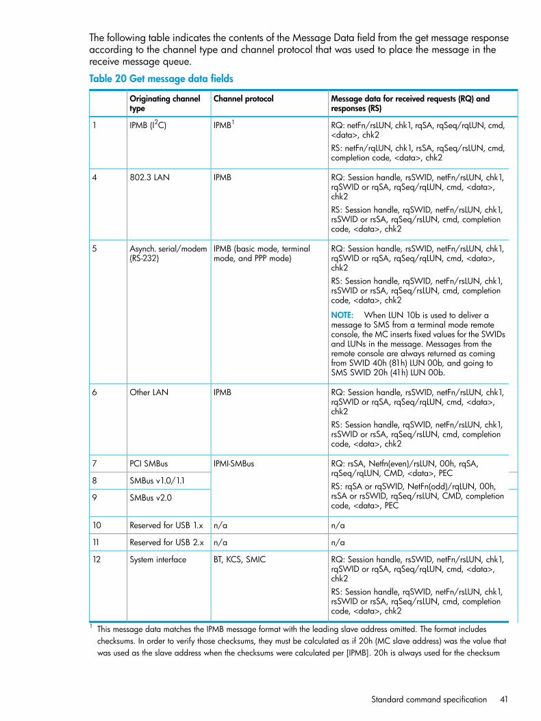
The following table indicates the contents of the Message Data field from the get message responseaccording to the channel type and channel protocol that was used to place the message in thereceive message queue.
Table 20 Get message data fields
Message data for received requests (RQ) andresponses (RS)
Channel protocolOriginating channeltype
RQ: netFn/rsLUN, chk1, rqSA, rqSeq/rqLUN, cmd,<data>, chk2
IPMB1IPMB (I2C)1
RS: netFn/rqLUN, chk1, rsSA, rqSeq/rsLUN, cmd,completion code, <data>, chk2
RQ: Session handle, rsSWID, netFn/rsLUN, chk1,rqSWID or rqSA, rqSeq/rqLUN, cmd, <data>,chk2
IPMB802.3 LAN4
RS: Session handle, rqSWID, netFn/rsLUN, chk1,rsSWID or rsSA, rqSeq/rsLUN, cmd, completioncode, <data>, chk2
RQ: Session handle, rsSWID, netFn/rsLUN, chk1,rqSWID or rqSA, rqSeq/rqLUN, cmd, <data>,chk2
IPMB (basic mode, terminalmode, and PPP mode)
Asynch. serial/modem(RS-232)
5
RS: Session handle, rqSWID, netFn/rsLUN, chk1,rsSWID or rsSA, rqSeq/rsLUN, cmd, completioncode, <data>, chk2
NOTE: When LUN 10b is used to deliver amessage to SMS from a terminal mode remoteconsole, the MC inserts fixed values for the SWIDsand LUNs in the message. Messages from theremote console are always returned as comingfrom SWID 40h (81h) LUN 00b, and going toSMS SWID 20h (41h) LUN 00b.
RQ: Session handle, rsSWID, netFn/rsLUN, chk1,rqSWID or rqSA, rqSeq/rqLUN, cmd, <data>,chk2
IPMBOther LAN6
RS: Session handle, rqSWID, netFn/rsLUN, chk1,rsSWID or rsSA, rqSeq/rsLUN, cmd, completioncode, <data>, chk2
RQ: rsSA, Netfn(even)/rsLUN, 00h, rqSA,rqSeq/rqLUN, CMD, <data>, PEC
IPMI-SMBusPCI SMBus7
SMBus v1.0/1.18RS: rqSA or rqSWID, NetFn(odd)/rqLUN, 00h,rsSA or rsSWID, rqSeq/rsLUN, CMD, completioncode, <data>, PEC
SMBus v2.09
n/an/aReserved for USB 1.x10
n/an/aReserved for USB 2.x11
RQ: Session handle, rsSWID, netFn/rsLUN, chk1,rqSWID or rqSA, rqSeq/rqLUN, cmd, <data>,chk2
BT, KCS, SMICSystem interface12
RS: Session handle, rqSWID, netFn/rsLUN, chk1,rsSWID or rsSA, rqSeq/rsLUN, cmd, completioncode, <data>, chk2
1 This message data matches the IPMB message format with the leading slave address omitted. The format includeschecksums. In order to verify those checksums, they must be calculated as if 20h (MC slave address) was the value thatwas used as the slave address when the checksums were calculated per [IPMB]. 20h is always used for the checksum
Standard command specification 41

calculation for the receive message queue data whenever IPMB is listed as the originating bus and with IPMB as thechannel protocol.
Send message commandThis command is available to the MC.The send message command is used for bridging IPMI messages between channels, and betweenthe SMS and a given channel.For IPMI v2.0 the send message command has been updated to include the ability to indicatewhether a message must be sent authenticated or with encryption (for target channels on whichauthentication and/or encryption are supported and configured).
Table 21 Send message command request and response data
Data fieldRequest databyte number
Channel number1
No tracking. The MC reformats the message for the selected channel but doesnot track the originating channel, sequence number, or address information.
00b =[7:6]
This option is typically used when software sends a message from the systeminterface to another media. Software will typically use no tracking when itdelivers sends a message from the system interface to another channel, suchas IPMB. In this case, the software formats the encapsulated message so thatwhen it appears on the other channel, it appears to have been directlyoriginated by MC LUN 10b. See “MC LUN 10b” (page 148) for moreinformation.
Track request. The MC records the originating channel, sequence number,and addressing information for the requester, and then reformats the message
01b =
for the protocol of the destination channel. When a response is returned, theMC looks up the requester’s information and format the response messagewith the framing and destination address information and reformats theresponse for delivery back to the requester. This option is used for deliveringIPMI request messages from non-SMS (non-system interface) channels. See“Send Message command with response tracking” (page 149) for moreinformation.
Send raw (optional). This option is primarily provided for test purposes. It mayalso be used for proprietary messaging purposes. The MC simply delivers the
10b =
encapsulated data to the selected channel in place of the IPMI message data.If the channel uses sessions, the first byte of the message data field must bea session handle. The MC must return a non-zero completion code if an attemptis made to use this option for a given channel and the option is not supported.It is recommended that completion code CCh be returned for this condition.
Reserved11b =
Send message with encryption. MC returns an error completion code if thisencryption is unavailable.
1b =[5]
Encryption not required. The message is sent unencrypted if that option isavailable under the given session. Otherwise, the message is sent encrypted.
0b =
Send message with authentication. MC returns an error completion code ifthis authentication is unavailable.
1b =[4]
Authentication not required. Behavior is dependent on whether authenticationis used and whether the target channel is running an IPMI v1.5 or IPMIv2.0/RMCP+ session, as follows:
0b =
• IPMI v1.5 sessions default to sending the message with authentication ifthat option is available for the session.
• IPMI v2.0/RMCP+ sessions send the message unauthenticated if that optionis available under the session. Otherwise, the message is sent withauthentication.
42 Command specification

Table 21 Send message command request and response data (continued)
Channel number where to send the message[3:0]
Message data. Format dependent on target channel type.2:N
Data fieldRequest databyte number
Completion code1Generic, plus additional command-specific completion codes: 80h = Invalid session handle. Thesession handle does not match up with any currently active sessions for this channel.If channel medium = IPMB, SMBus, or PCI management bus (This status is recommended for applicationsthat need to access low-level I2C or SMBus devices).
• 81h = Lost arbitration
• 82h = Bus error
• 83h = NAK on write
Response data(2:N)This data will only be present when using the send message command to originate requests fromIPMB or PCI management bus to other channels such as LAN or serial/modem. It is not present in theresponse to a send message command delivered via the system interface.
NOTE: The MC does not parse messages that are encapsulated in a send message commandand does not know what privilege level should be associated with an encapsulated message. Thus,messages that are sent to a session using the send message command are always output usingthe authentication type that was negotiated when the session was activated.
The following table summarizes the contents of the message data field when the send messagecommand is used to deliver an IPMI message to different channel types. In most cases, the formatof message information the message data field follows are the same used for the IPMB, with twotypical exceptions:• When the message is delivered to channels without physical slave devices, a SWID field takes
the place of the slave address field.• When the message is delivered to a channel that supports sessions, the first byte of the message
data holds a session handle.
Table 22 Send message data fields
Message data for sending requests (RQ) andresponses (RS)
Target channel protocolTarget channel type
RQ: rsSA, netFn/rsLUN, chk1, rqSA,rqSeq/rqLUN, cmd, <data>, chk2
IPMBIPMB (I2C)1
RS: rqSA, netFn/rqLUN, chk1, rsSA, rqSeq/rsLUN,cmd, completion code, <data>, chk2
RQ: Session handle1, rsSWID, netFn/rsLUN, chk1,rqSWID or rqSA, rqSeq/rqLUN, cmd, <data>,chk2
IPMB+session header802.3 LAN4
RS: Session handle1, rqSWID, netFn/rsLUN, chk1,rsSWID or rsSA, rqSeq/rsLUN, cmd, completioncode, <data>, chk2
RQ: Session handle1, rsSWID, netFn/rsLUN, chk1,rqSWID or rqSA, rqSeq/rqLUN, cmd, <data>,chk2
IPMB (basic mode, terminalmode, and PPP mode)
Asynch. serial/modem(RS-232)
5
RS: Session handle1, rqSWID, netFn/rsLUN, chk1,rsSWID or rsSA, rqSeq/rsLUN, cmd, completioncode, <data>, chk2
Standard command specification 43

Table 22 Send message data fields (continued)
Message data for sending requests (RQ) andresponses (RS)
Target channel protocolTarget channel type
NOTE: Terminal mode has a single, fixed SWIDfor the remote console. Software using sendmessage to deliver a message to a terminal moderemote console should use their SWID or slaveaddress as the source of the request or response,and the terminal mode SWID (40h) as thedestination.
RQ: Session handle1, rsSWID, netFn/rsLUN, chk1,rqSWID or rqSA, rqSeq/rqLUN, cmd, <data>,chk2
IPMBOther LAN6
RS: Session handle1, rqSWID, netFn/rsLUN, chk1,rsSWID or rsSA, rqSeq/rsLUN, cmd, completioncode, <data>, chk2
RQ: rsSA, netFn/rsLUN, chk1, rqSA,rqSeq/rqLUN, cmd, <data>, chk2
IPMI-SMBusPCI SMBus7
SMBus v1.0/1.18RS: rqSA, netFn/rqLUN, chk1, rsSA, rqSeq/rsLUN,cmd, completion code, <data>, chk2SMBus v2.09
n/an/aReserved for USB 1.x10
n/an/aReserved for USB 2.x11
RQ: rsSA, netFn/rsLUN, chk1, rqSA,rqSeq/rqLUN, cmd, <data>, chk2
System interface12
RS: rqSA, netFn/rqLUN, chk1, rsSA, rqSeq/rsLUN,cmd, completion code, <data>, chk2
NOTE: MC adds session handle informationwhen it puts the message into the receive messagequeue .
1 The session handle identifies a particular active session on the given channel. The MC assigns a different value to eachtime a new session is activated. A typical implementation keeps track of the last value that was assigned and incrementit before assigning it to a new active session when the activate session command has been accepted. Softwaremust include this field for channels where the get channel info command indicates that the channel supports sessions.
Get system GUID commandThis command is available to the MC.This optional, though highly recommended, command can be used to return a GUID (also knownas a UUID), for the managed system to support the remote discovery process and other operations.The format of the ID follows the octet format specified in [RFC 4122]. [RFC4122] specifies fourdifferent versions of UUID formats and generation algorithms suitable for use for a GUID in IPMI.
• Time based — version 1 (0001b)
• Name based:
version 3 (0011b) MD5 hash◦◦ version 4 (0100b) Pseudo-random
◦ version 5 SHA1 hash
[SMBIOS] does not specify a particular specification or version for UUID generation. In general,if it remains unspecified, the version 1 format is recommended by the IPMI specification for new
44 Command specification

system implementations. However, versions 3, 4, or 5 formats are also allowed. A system GUIDshould not change over the lifetime of the system.If the MC is on a removable card that can be moved to another system, the vendor of the card orsystem vendor should provide a mechanism for generating a new system GUID or retrieving theSMBIOS UUID from the given system.Since the GUID is typically permanently assigned to a system, an interface that would allow theGUID to be configured or changed is not specified. For systems that support [SMBIOS], the systemGUID that is returned by the MC should match the UUID field value in the SMBIOS systeminformation (type 1) record.The session header (session request data and session response data) values shown in the followingtable illustrate the values that would be used to execute a get system GUID command outsideof an active session. The get system GUID is always accepted outside of an active session. Theget system GUID command can also be executed within the context of an active session(providing the user is operating at higher than callback privilege). When the get system GUIDcommand is executed in the context of an active session, the session header fields must have correctvalues according to the authentication, session ID, and session sequence number information thatwas negotiated for the session.
Session header fields request and response data prior when used prior to session activationauthentication type = NONEsession seq# = null (0’s)Session ID = null (0’s)AuthCode = NOT PRESENT
Table 23 Get system GUID command response data
Data fieldResponse databyte number
Completion code1
GUID bytes 1 through 16.2:17
Set system info parameters commandThis command is available to the MC.This command is used for setting system information parameters such as system name andBIOS/system firmware revision information.
Table 24 Set system info parameters command request and response data
Data fieldRequest databyte number
Parameter selector1
Configuration parameter data, per Table 26 (page 46)2:N
Data fieldResponse databyte number
Completion code1• 80h = parameter not supported
• 81h = attempt to set the set in progress value (in parameter #0) when not in the set complete state.(This completion code provides a way to recognize that another party has already claimed theparameters).
• 82h = attempt to write read-only parameter
Standard command specification 45

Get system info parameters commandThis command is available to the MC.This command is used for retrieving system information parameters from the set system infoparameters command.
Table 25 Get system info parameters command request and response data
Data fieldRequest databyte number
[7]1• 0b = get parameter
• 1b = get parameter revision only
[6:0] — reserved
Parameter selector2
Set selector. Selects a given set of parameters under a given parameter selector value. 00h ifparameter does not use a set selector.
3
Block selector (00h if parameter does not require a block number)4
Data fieldResponse databyte number
Completion code1Generic codes, plus the command-specific completion code: 80h = parameter not supported.
[7:0] — Parameter revision. Format:2• MSN = present revision
• LSN = oldest revision parameter that is backward compatible
• 11h for parameters in this specification
The following data bytes are not returned when the get parameter revision only bit is 1b.
Configuration parameter data, per “System info parameters” (page 46). If the rollback feature isimplemented, the MC makes a copy of the existing parameters when the set in progress state becomes
3:N
asserted. (See the set in progress parameter #0). While the set in progress state is active, the MCreturns data from this copy of the parameters, plus any uncommitted changes that were made to thedata. Otherwise, the MC returns parameter data from non-volatile storage.
Table 26 System info parameters
Parameter data (non-volatile unless otherwise noted)1#Parameter
Data 1 - This parameter is used to indicate when any of the following parametersare being updated, and when the updates are completed. The bit is primarily
0Set in progress (volatile)
provided to alert software that some other software or utility is in the processof making changes to the data.An implementation can also elect to provide a rollback feature that uses thisinformation to decide whether to roll back to the previous configurationinformation, or to accept the configuration change.If used, the roll back restores all parameters to their previous state. Otherwise,the change takes effect when the write occurs.
Reserved[7:2]
Set complete. If a system reset or transition topowered down state occurs while set in progress
00b =[1:0]
is active, the MC goes to the set complete state.If rollback is implemented, going directly to setcomplete without first doing a commit writecauses any pending write data to be discarded.
46 Command specification
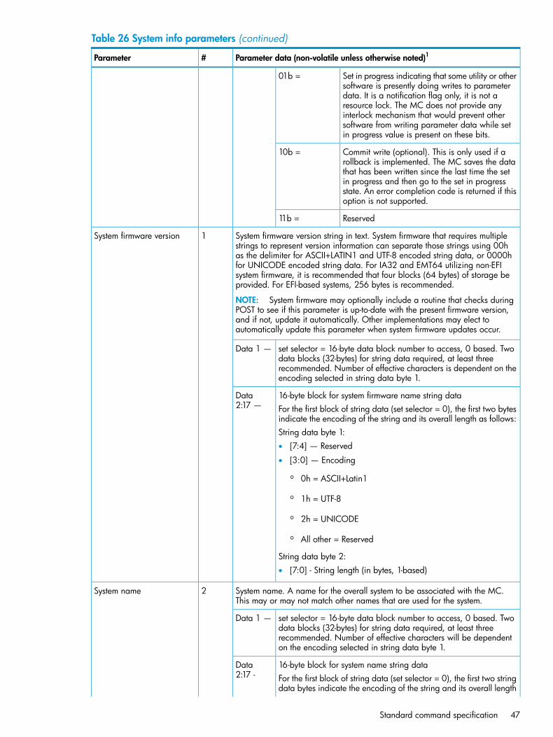
Table 26 System info parameters (continued)
Parameter data (non-volatile unless otherwise noted)1#Parameter
Set in progress indicating that some utility or othersoftware is presently doing writes to parameter
01b =
data. It is a notification flag only, it is not aresource lock. The MC does not provide anyinterlock mechanism that would prevent othersoftware from writing parameter data while setin progress value is present on these bits.
Commit write (optional). This is only used if arollback is implemented. The MC saves the data
10b =
that has been written since the last time the setin progress and then go to the set in progressstate. An error completion code is returned if thisoption is not supported.
Reserved11b =
System firmware version string in text. System firmware that requires multiplestrings to represent version information can separate those strings using 00h
1System firmware version
as the delimiter for ASCII+LATIN1 and UTF-8 encoded string data, or 0000hfor UNICODE encoded string data. For IA32 and EMT64 utilizing non-EFIsystem firmware, it is recommended that four blocks (64 bytes) of storage beprovided. For EFI-based systems, 256 bytes is recommended.
NOTE: System firmware may optionally include a routine that checks duringPOST to see if this parameter is up-to-date with the present firmware version,and if not, update it automatically. Other implementations may elect toautomatically update this parameter when system firmware updates occur.
set selector = 16-byte data block number to access, 0 based. Twodata blocks (32-bytes) for string data required, at least three
Data 1 —
recommended. Number of effective characters is dependent on theencoding selected in string data byte 1.
16-byte block for system firmware name string dataData2:17 — For the first block of string data (set selector = 0), the first two bytes
indicate the encoding of the string and its overall length as follows:String data byte 1:• [7:4] — Reserved
• [3:0] — Encoding
◦ 0h = ASCII+Latin1
◦ 1h = UTF-8
◦ 2h = UNICODE
◦ All other = Reserved
String data byte 2:• [7:0] - String length (in bytes, 1-based)
System name. A name for the overall system to be associated with the MC.This may or may not match other names that are used for the system.
2System name
set selector = 16-byte data block number to access, 0 based. Twodata blocks (32-bytes) for string data required, at least three
Data 1 —
recommended. Number of effective characters will be dependenton the encoding selected in string data byte 1.
16-byte block for system name string dataData2:17 - For the first block of string data (set selector = 0), the first two string
data bytes indicate the encoding of the string and its overall length
Standard command specification 47

Table 26 System info parameters (continued)
Parameter data (non-volatile unless otherwise noted)1#Parameter
as follows. There is no required value to be set or used for anybytes that are past the string length.String data byte 1:• [7:4] — Reserved
• [3:0] — Encoding
◦ 0h = ASCII+Latin1
◦ 1h = UTF-8
◦ 2h = UNICODE
◦ All other = Reserved
String data byte 2:• [7:0] - String length (in bytes, 1-based)
Primary operating system name. The OS that the system boots to for this MCaccording to the default configuration of its system firmware. In systems that
3Primary operating systemname (non-volatile)
may have multiple physical partitions, this reflects the OS for the partition thatholds the given MC. For systems that have virtual machine capability beingutilized (where more than one virtual systems may be sharing a physical MC),it is recommended that this value hold the name of the virtual machine monitor(VMM) software or VMM type).
Set selector = 16-byte data block number to access, 0 based. Twodata blocks (32-bytes) for string data required, at least three
Data 1
recommended. Number of effective characters will be dependenton the encoding selected in string data byte 1.
16-byte block for system name string dataData2:17 For the first block of string data (set selector = 0), the first two bytes
indicate the encoding of the string and its overall length as follows.There is no required value to be set or used for any bytes that arepast the string length.String data byte 1:• [7:4] — Reserved
• [3:0] — Encoding
◦ 0h = ASCII+Latin1
◦ 1h = UTF-8 (ls-byte first)
◦ 2h = UNICODE (ls-byte first)
◦ All other = Reserved
String data byte 2:• [7:0] - string length (in bytes, 1-based)
Present operating system name. The name of the operating system that ispresently running and able to access this MC’s system interface. The MC
4Operating system name(volatile)
automatically clears this value by zeroing out the string length on system powercycles and resets.In systems that may have multiple physical partitions, this reflects the OS forthe partition that holds the given MC. For systems that have virtual machinecapability being utilized (where more than one virtual systems may be sharinga physical MC), it is recommended that this value hold the name of the virtualmachine monitor (VMM) software or VMM type.
48 Command specification

Table 26 System info parameters (continued)
Parameter data (non-volatile unless otherwise noted)1#Parameter
Set selector = 16-byte data block number to access, 0 based. Twodata blocks (32-bytes) for string data required, at least three
Data 1
recommended. Number of effective characters is dependent on theencoding selected in string data byte 1.
16-byte block for system name string dataData2:17 For the first block of string data (set selector = 0), the first two bytes
indicate the encoding of the string and its overall length as follows.There is no required value to be set or used for any bytes that arepast the string length.String data byte 1:• [7:4] — Reserved
• [3:0] — Encoding
◦ 0h = ASCII+Latin1
◦ 1h = UTF-8
◦ 2h = UNICODE
◦ All other = Reserved
String data byte 2:• [7:0] - String length (in bytes, 1-based)
This range is available for special OEM system information parameters.192 …255
OEM
1 Choice of system manufacturing defaults for non-volatile parameters is left to the system manufacturer unless otherwisespecified.
Master write-read commandThis command can be used for low-level I2C/SMBus write, read, or write-read access to the IPMBor private busses behind a management controller. The command can also be used for providinglow-level access to devices that provide an SMBus slave interface.
NOTE: In Moonshot, this command is not available over LAN.
Table 27 Master write-read command request and response data
Data fieldIPMI requestdata bytenumber
Bus ID:1
Channel number (ignored when bus type=1b[7:4]
Bus ID, 0–based (always 000b for public bus ([bus type=0b])[3:1]
Bus type:[0]
Public (for example, IPMB or PIC Management) bus. The channel numbervalue is used to select the target bus.
0b =
Private bus (the bus ID value is used to select the target bus.)1b =
Requested maximum privilege level2
Slave address[7:1]
Reserved. Write a 0.[0]
Standard command specification 49

Table 27 Master write-read command request and response data (continued)
Read count. Number of bytes to read, 1 based. 0 equals not bytes to read. The maximum read countshould be at least 34 bytes. This allows the command to be used for an SMBus Block Read. This is
3
required if the command provides access to an SMBus or IPMB. Otherwise, if FRU SEEPROM devicesare accessible, at least 31 bytes must be supported. Note than an implementation that supports fewerbytes can be supported if none of the devices to be accessed can handle the recommended minimum.
Data to write. This command should support at least 35 bytes of write data. This allows the commandto be used for an SMBus Block Write with PEC. Otherwise, if FRU SEEPROM devices are accessible,
4:N
at least 31 bytes must be supported. Note that an implementation is allowed to support fewer bytesif none of the devices to can handle the recommended minimum.
Data fieldIPMI responsedata bytenumber
Completion code1A management controller shall return an error Completion Code if an attempt is made to access anunsupported bus. This is a generic response but also may include the following command specificcodes:• 81h—Lost arbitration
• 82h—Bus error
• 83h—NAK on write
• 84h—Truncated read
Bytes read from specified slave address. This field will be absent if the read count is 0. The controllerterminates the I2C transaction with a STOP condition after reading the requested number of bytes.
(2:M)
Get channel authentication capabilities commandThis command is available to the MC.This command is sent in unauthenticated (clear) format. This command is used to retrieve capabilityinformation about the channel from which the message is delivered, or for a particular channel.The command returns the authentication algorithm support for the given privilege level. Whenactivating a session, the privilege level passed in this command is normally the same requestedmaximum privilege level that is used for a subsequent activate session command.MC implementations of IP-based channels must support the get channel authenticationcapabilities command using the IPMI v1.5 packet format. BMCs that support IPMI v2.0 RMCP+must also support the command using the IPMI v2.0/RMCP+ format.The get channel authentication capabilities command can also be used as a no-op“ping” to keep a session from timing out.
Session header fields request and response data prior when used prior to session activationauthentication type = NONE/payload type = IPMI messagesession seq# = null (0’s)Session ID = null (0’s)AuthCode = NOT PRESENT
Table 28 Get channel authentication capabilities command request and response data
Data fieldIPMI requestdata bytenumber
Channel number1
50 Command specification

Table 28 Get channel authentication capabilities command request and response data (continued)
Get IPMI v2.0+ extended data. If the given channel supports authenticationbut does not support RMCP+ (such as a serial channel), then the responsedata should return with bit [5] of byte 4 = 0b, byte 5 should return 01h,
1b =[7]
Backward compatible with IPMI v1.5. Result response data only returns bytes1:9, bit [7] of byte 3 (authentication type support) and bit [5] of byte 4 returnsas 0b, bit [5] of byte 5 returns 00h.
0b =
Reserved[6:4]
Channel number[3:0]
Channel numbers0hBh, Fh =
Retrieve information for the channel from which this request was issued.Eh =
Requested maximum privilege level2
Reserved[7:4]
Requested privilege level[3:0]
Reserved0h =
Callback level1h =
User level2h =
Operator level3h =
Administrator level4h =
OEM proprietary level5h =
Data fieldIPMI responsedata bytenumber
Completion code1
Channel number on which the authentication capabilities is being returned. If the channel number inthe request was set to Eh, this returns the channel number for the channel where the request wasreceived.
2
Authentication type support. Returns the setting of the authentication type enable field from theconfiguration parameters for the given channel that corresponds to the requested maximum privilegelevel.
3
IPMI v2.0+ extended capabilities available. See Extended capabilities fieldbelow.
1b =[7]
IPMI v1.5 support only.0b =
Reserved[6]
IPMI v1.5 authentication type(s) enabled for given requested maximum privilege level.[5:0]
1b = SupportedAll bits:0b = Authentication type not available for use
OEM proprietary (per OEM identified by the IANA OEM ID in the RMCP pingresponse)
[5]
Straight password / key[4]
Reserved[3]
MD5[2]
MD2[1]
Standard command specification 51

Table 28 Get channel authentication capabilities command request and response data (continued)
None[0]
Reserved[7:6]4
KG status (two-key login status). Applies to v2.0/RMCP+ RAKP authentication only.Otherwise, ignore as reserved.
[5]
KG is set to default (all 0’s). User key KUID is used in place of KG in RAKP.(Knowledge of KG not required for activating session.)
0b =
KG is set to non-zero value. (Knowledge of both KG and user password (ifnot anonymous login) required for activating session.)
1b =
Following bits apply to IPMI v1.5 and v2.0:
Per-message authentication status[4]
Per-message authentication is enabled. Packets to the MC must be authenticatedper authentication type used to activate the session, and the user levelauthentication setting.
0b =
Per-message authentication is disabled. Authentication type none acceptedfor packets to the MC after the session has been activated.
1b =
User level authentication status[3]
User level authentication is enabled. User level commands must beauthenticated per authentication type used to activate the session.
0b =
User level authentication is disabled. Authentication type none accepted foruser level commands to the MC.
1b =
Anonymous login status. This parameter returns values that tells the remote console whetherthere are users on the system that have ‘null’ usernames. This can be used to guide the waythe remote console presents login options to the user.
[2:0]
1b = Non-null usernames enabled. (One or more users are enabled that havenon-null usernames).
[2]
1b = Null usernames enabled. (One or more users that have a null username,but non-null password, are presently enabled).
[1]
1b = Anonymous login enabled. (A user that has a null username and nullpassword is presently enabled).
[0]
For IPMI v1.5: - Reserved5
For IPMI v2.0+: - Extended capabilities
Reserved[7:2]
Channel supports IPMI v2.0 connections1b =[1]
Channel supports IPMI v1.5 connections1b =[0]
OEM ID. IANA enterprise number for OEM/Organization that specified the particular OEMauthentication type for RMCP. Least significant byte first. Return 00h, 00h, 00h if no OEM authenticationtype available.
6:8
OEM auxiliary data. Additional OEM-specific information for the OEM authentication type for RMCP.Return 00h if no OEM authentication type available.
9
Get Channel Cipher Suites CommandThis command can be executed prior to establishing a session with the MC. The command is usedto look up what authentication, integrity, and confidentiality algorithms are supported. The algorithmsare used in combination as ‘Cipher Suites’. This command only applies to implementations thatsupport IPMI v2.0/RMCP+ sessions.
52 Command specification

The data is accessed 16-bytes at a time starting from List Index field value of 0 in the request andthen repeating the request incrementing the List Index field each time until fewer than 16-bytes ofalgorithm data (or no algorithm data) is returned in the response, or the maximum List Index valuehas been reached.A given Cipher Suite may only be available for establishing a session at a particular maximumprivilege level or lower. For example, a Cipher Suite that has a privilege level of ‘Admin’ cantherefore be used for any privilege level, while a privilege level of User can only be used forestablish sessions with a Maximum Requested Privilege Level of User or Callback.Because the authentication algorithm specifies the steps for authenticating the user, it is a necessarypart of session establishment. Therefore an authentication algorithm number is required for allCipher Suites. It is possible that a given Cipher Suite may not specify use of an integrity orconfidentiality algorithm. If the Cipher Suite has integrity and/or confidentiality of 'none', then allthe same steps for establishing a session are used (open session request/response, RAKP messages)- but the integrity (AuthCode) and confidentiality fields will be absent in packets for that are sentunder the session.
Table 29 Get channel cipher suites command request and response data
Data fieldIPMI RequestData Byte
Channel Number1
Reserved[7:4]
Channel number0h-Bh, Fh = Channel numbers
[3:0]
Eh = retrieve information for channel this request was issued on.
Payload Type.2[7:6] - reserved[5:0] - Payload Type numberTypically 00h (IPMI).The Payload Type number is used to look up the Security Algorithm support when establishing aseparate session for a given payload type.
List Index.3
1b = list algorithms by Cipher Suite[7]
0b = list supported algorithms1
Reserved[6]
List index (00h-3Fh). 0h selects the first set of 16, 1h selects the next set of 16, and soon.
[5:0]
00h = Get first set of algorithm numbers. The MC returns sixteen (16) bytes at a time perindex, starting from index 00h, until the list data is exhausted, at which point it will 0bytes or <16 bytes of list data.
Data fieldIPMI ResponseData Byte
Completion Code1
Channel Number2Channel number that the Authentication Algorithms are being returned for. If the channel numberin the request was set to Eh, this will return the channel number for the channel that the request wasreceived on.
Cipher Suite Record data bytes, per Table 22-18, Cipher Suite Record(3:18)
Standard command specification 53
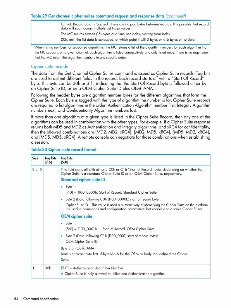
Table 29 Get channel cipher suites command request and response data (continued)
Format. Record data is ‘packed’; there are no pad bytes between records. It is possible that recorddata will span across multiple List Index values.The MC returns sixteen (16) bytes at a time per index, starting from index00h, until the list data is exhausted, at which point it will 0 bytes or <16 bytes of list data.
1 When listing numbers for supported algorithms, the MC returns a list of the algorithm numbers for each algorithm thatthe MC supports on a given channel. Each algorithm is listed consecutively and only listed once. There is no requirementthat the MC return the algorithm numbers in any specific order.
Cipher suite recordsThe data from the Get Channel Cipher Suites command is issued as Cipher Suite records. Tag bitsare used to delimit different fields in the record. Each record starts off with a “Start Of Record”byte. This byte can be 30h or 31h, indicating that the Start Of Record byte is followed either byan Cipher Suite ID, or by a OEM Cipher Suite ID plus OEM IANA.Following the header bytes are algorithm number bytes for the different algorithms that form theCipher Suite. Each byte is tagged with the type of algorithm the number is for. Cipher Suite recordsare required to list algorithms in the order: Authentication Algorithm number first, Integrity Algorithmnumbers next, and Confidentiality Algorithm numbers last.If more than one algorithm of a given type is listed in the Cipher Suite Record, then any one of thealgorithms can be used in combination with the other types. For example, if a Cipher Suite responsereturns both MD5 and MD2 as Authentication and Integrity algorithms, and xRC4 for confidentiality,then the allowed combinations are [MD2, MD2, xRC4], [MD2, MD5, xRC4], [MD5, MD2, xRC4],and [MD5, MD5, xRC4]. A remote console can negotiate for those combinations when establishinga session.
Table 30 Cipher suite record format
Tag bits[5:0]
Tag bits[7:6]
Size
This field starts off with either a C0h or C1h "Start of Record" byte, depending on whether theCipher Suite is a standard Cipher Suite ID or an OEM Cipher Suite, respectively.
2 or 5
Standard cipher suite ID• Byte 1:
[7:0] = 1100_0000b. Start of Record, Standard Cipher Suite.
• Byte 2 (Data following C0h (1100_0000b) start of record byte):Cipher Suite ID—This value is used a numeric way of identifying the Cipher Suite on the platform.It’s used in commands and configuration parameters that enable and disable Cipher Suites.
OEM cipher suite• Byte 1:
[5:0] = 1100_0001b — Start of Record, OEM Cipher Suite.
• Byte 2 (Data following C1h (1100_0001) start of record byte):OEM Cipher Suite ID
Byte 3:5 - OEM IANALeast significant byte first. 3-byte IANA for the OEM or body that defined the CipherSuite.
[5:0] = Authentication Algorithm Number.00b1A Cipher Suite is only allowed to utilize one Authentication algorithm.
54 Command specification

Table 30 Cipher suite record format (continued)
Tag bits[5:0]
Tag bits[7:6]
Size
[5:0] = Integrity Algorithm Number(s).01bvar
[5:0] = Confidentiality Algorithm Number(s).10bvar
Cipher suite ID numbersThe following table provides the number ranges and assignments for Cipher Suite IDs. The CipherSuite ID values are used as a way to identify different Cipher Suites in configuration parametersand IPMI commands.The OEM IDs do not correspond to a particular Cipher Suite, but are handles that can be used toidentify the Cipher Suite on a particular implementation of a MC. I.e. the OEM Cipher Suitecorresponding to “80h” can be different from one MC to the next. These handles can, however,be used in configuration parameters and commands the same way as the IPMI-defined CipherSuite IDs.The Get Channel Cipher Suites command will return the algorithms used to form a given CipherSuite (those numbers can then be used by a remote console in the commands for establishing asession). For OEM defined Cipher Suites, the Get Channel Cipher Suites command will also returnthe IANA for the OEM or body that defined the Cipher Suite.
Table 31 Cipher suite ID numbers
ConfidentialityAlgorithm(s)
Integrity Algorithm(s)AuthenticationAlgorithm
Cipher SuiteCharacteristicsID
NoneNoneRAKP-none00h, 00h, 00hno password0
NoneNoneRAKP-HMAC-SHA101h, 00h, 00hS1
NoneHMAC-SHA1-9601h, 01h, 00hS, A2
AES-CBC-12801h, 01h, 01hS, A, E3
xRC4-12801h, 01h, 02hS, A, E4
xRC4-4001h, 01h, 03hS, A, E5
NoneNoneRAKP-HMAC-MD502h, 00h, 00hS6
NoneHMAC-MD5-12802h, 02h, 00hS, A7
AES-CBC-12802h, 02h, 01hS, A, E8
xRC4-12802h, 02h, 02hS, A, E9
xRC4-4002h, 02h, 03hS, A, E10
NoneMD5-12802h, 03h, 00hS, A11
AES-CBC-12802h, 03h, 01hS, A, E12
xRC4-12802h, 03h, 02hS, A, E13
xRC4-4002h, 03h, 03hS, A, E14
OEM specifiedOEM specifiedOEM specifiedOEM specifiedOEM specified80h-BFh
----reservedC0h-FFh
Key:S = Authenticated session setup (correct role, username and password/key required to establish session.)
Standard command specification 55

Table 31 Cipher suite ID numbers (continued)
ConfidentialityAlgorithm(s)
Integrity Algorithm(s)AuthenticationAlgorithm
Cipher SuiteCharacteristicsID
A = Authenticated payload data supported.E = Authentication and encrypted payload data supported.
Set session privilege level commandThis command is available to the MC.This command is sent in authenticated format. When a session is activated, the session is set to aninitial privilege level. A session that is activated at a maximum privilege level of callback is set toan initial privilege level of callback and cannot be changed. All other sessions are initially set touser level, regardless of the maximum privilege level requested in the activate sessioncommand. The remote console must raise the privilege level of the session using this command inorder to execute commands that require a greater-than-user level of privilege.This command cannot be used to set a privilege level higher than the lowest of the privilege levelset for the user (via the set user access command) and the privilege limit for the channel thatwas set via the set channel access command. The specification allows a session to be usedacross multiple channels. The maximum privilege limit and authentication are based on the userprivilege and channel limits. Since these can vary on a per channel basis, an implementationcannot simply assign a single privilege limit to a given session but must authenticate incomingmessages according to the specific settings for the channel and the user on a per-channel basis.
Table 32 Set session privilege level command request and response data
Data fieldIPMI requestdata bytenumber
Requested privilege level1• [7:4] — Reserved
• [3:0] — Privilege level
◦ 0h — No change, just return present privilege level
◦ 1h — Reserved
◦ 2h — Change to user level
◦ 3h — Change to operator level
◦ 4h — Change to administrator level
◦ 5h — Change to OEM proprietary level
◦ All other = Reserved
Data fieldIPMI responsedata bytenumber
Completion code. Generic, plus following command specific:1• 80h = Requested level not available for this user
• 81h = Requested level exceeds channel and/or user privilege limit
• 82h = Cannot disable user level authentication
New privilege level (or present level if return present privilege level was selected.)2
56 Command specification

Close session commandThis command is used to immediately terminate a session in progress. It is typically used to closethe session that the user is communicating over, though it can be used to terminate other sessionsin progress (provided that the user is operating at the appropriate privilege level, or the commandis executed over a local channel, such as the system interface).
Table 33 Close session command request and response data
Data fieldIPMI requestdata bytenumber
Session ID. For IPMI v2.0/RMCP+ this is the Managed System Session ID value that was generatedby the MC, not the ID from the remote console. If Session ID = 0000_0000h then an implementation
1:4
can optionally enable this command to take an additional byte of parameter data that allows a sessionhandle to be used to close a session.
Session Handle. Only present if Session ID = 0000_0000h.(5)
Data fieldIPMI responsedata bytenumber
Completion code.1• 87h = Invalid session ID in request
• 88h = Invalid Session Handle in request
• 82h = Cannot disable user level authentication
Get session info commandThis command is available to the MC.This command is used to get information regarding which users presently have active sessions,and, when available, addressing information for the party that has established the session. Aportion of the response is dependent on the type of channel.For IPMI v2.0, a previously reserved field has been defined to hold a value indicating whether asession operating on a channel of channel type = 802.3 LAN is presently using IPMI v1.5 orv2.0/RMCP+ protocols.
Table 34 Get session info command request and response data
Data fieldIPMI requestdata bytenumber
Session index. This value is used to select entries in a logical sessions table maintained by themanagement controller. Information for all active sessions can be retrieved by incrementing the sessionindex from 1 to N, where N is the number of entries in the active sessions table.
1
• 00h = Return information for the active session associated with the session where this commandwas received.
• N = Get information for Nth active session
• FEh = Look up session information according to the session handle passed in this request.
• FFh = Look up session information according to the session ID passed in this request.
Present if session index = FEh
Session handle. 00h = reserved.2
Present if session index = FFh:
Session ID. ID of session to look up session information. For IPMI v2.0/RMCP+ this is the session IDvalue that was generated by the MC, not the ID from the remote console.
2:5
Standard command specification 57

Table 34 Get session info command request and response data (continued)
Data fieldIPMI responsedata bytenumber
Completion code1
Session handle presently assigned to active session. FFh = reserved. Return 00h if no active sessionassociated with given session index.
2
Number of possible active sessions. This value reflects the number of possible entries (slots) in thesessions table.
3
• [7:6] — Reserved
• [5:0] — Session slot count. 1-based.
Number of currently active sessions on all channels on this controller.4• [7:6] — Reserved
• [5:0] — Active session count. 1-based. 0=no currently active sessions.
The following parameters are returned only if there is an active session corresponding to the given session index:
User ID for selected active session.5• [7:6] — Reserved
• [5:0] — User ID. 000000b = reserved.
Operating privilege level6• [7:4] — Reserved
• [3:0] — Present privilege level at which the user is operating.
[7:4] — Session protocol auxiliary data. For channel type = 802.3 LAN:7• 0h = IPMI v1.5
• 1h = IPMI v2.0/RMCP+
Channel in which the session was activated.[3:0] - Channel number
The following bytes 8:18 are optionally returned if channel type = 802.3 LAN:
IP address of remote console (MS-byte first). Address that was received in the activate sessioncommand that activated the session
8:11
MAC address (MS-byte first). Address that was received in the activate session command thatactivated the session.
12:17
Port number of remote console (LS-byte first). Port number that was received in UDP packet that heldthe activate session command that activated the session (for IPMI v1.5 packets) or that wasused for in the packet for RAKP Message 3 (for IPMI v2.0 / RMCP+ packets).
18:19
The following bytes 8:13 are returned if channel type = asynch. serial/modem:
Session/channel activity type:8• 0 = IPMI messaging session active
• 1 = Callback messaging session active
• 2 = Dial-out alert active
• 3 = TAP page active
Destination selector for active call-out session. 0 otherwise.9• [7:4] - Reserved
• [3:0] - Destination selector. Destination 0 is always present as a volatile destination that is usedwith the alert immediate command.
58 Command specification

Table 34 Get session info command request and response data (continued)
If PPP connection, the IP address of the remote console. (MS-byte first). 00h, 00h, 00h, 00h otherwise.10:13
The following additional bytes 14:15 are returned if channel type = asynch. serial/modem and connection is PPP:
Port address of remote console (LS-byte first). Address that was received in the activate sessioncommand that activated the session.
14:15
Get AuthCode commandThis command is available to the MC.This command is used to send a block of data to the MC, whereupon the MC returns a hash ofthe data together concatenated with the internally stored password for the given channel and user.This command allows a remote console to send an AuthCode and data block to system softwareon a remote platform, whereby the system software can validate the AuthCode by comparing itwith the AuthCode returned by the MC. This enables the MC to serve as a validation agent forremote requests that come through local system software instead of through a remote session directlywith the MC.The following is an outline of potential use of this capability. Remote console software could requestthat system software perform a particular operation. In response, local system software could delivera challenge string to the remote console, which would be required to hash it with the desiredpassword and return the AuthCode to the local system software. The local system software wouldthen perform the requested operation only if it found that the AuthCode matched the one returnedby the MC. The local software would typically implement mechanisms to bind the challenge stringto the requested operation to ensure that the challenge string and AuthCode combination onlyapplied to a given instance of the requested operation, and even from a particular remote console.
• Managed system delivers a random number token, S, to the console. In this example, theconsole uses S to identify a particular request. The managed system tracks outstanding Svalues, and expires them either because a valid message was received from a console thatused that token, or because the token was not used within a specified interval.
• Console determines: X = data to be authenticated
K1 = 16-byte signature of X and a sequence number = hash(X, S,SW_Authentication_Type). Where SW_Authentication_Type is any signature algorithmmanagement software wishes to use for providing a signature given X and S.
◦
◦ K2 = 16-byte hash of K1 and the password = hash(K1, PWD, Authentication_Type).Where Authentication_Type in this case is one of the supported authentication types forthe given MC.
• Console sends X, S, and K2 to software agents on the managed system.
• Software agent on the managed system calculates K1 from X and S that it received by locallycalculating K1=hash1(X, S, SW_Authentication_Type). The software also verifies that S is avalid outstanding token.
• Managed system passes K1 to MC. MC internally looks up password based on the user IDpassed in the get authcode command and produces: K2BMC= hash(K1, PWD,Authentication_Type).
• Managed system accepts data if software agents finds that K2 = K2BMC.
Standard command specification 59

Table 35 Get AuthCode command request and response data
Data fieldIPMI requestdata bytenumber
[7:6] - Authentication type / Integrity algorithm number1• 00b = IPMI v1.5 AuthCode algorithms
• 01b = IPMI v2.0/RMCP+ algorithm number
For [7:6] = 00b, IPMI v1.5 AuthCode number:• [5:4] - Reserved
• [3:0] - Hash type
◦ 0h = Reserved
◦ 1h = MD2
◦ 2h = MD5
◦ 3h = Reserved
◦ 4h = Reserved (change from IPMI v1.5). This results in an error completion code.
◦ 5h = OEM proprietary
◦ All other = Reserved
For [7:6] = 01b, IPMI v2.0/RMCP+ Integrity algorithm number• 5:0] - Integrity algorithm number. The user password is used as the starting key for the Integrity
algorithm, instead of session-dependent keys such as the session integrity key. The “none” Integritynumber (0) is illegal and results in an error completion code.
Channel number2• [7:4] - Reserved
• [3:0] - Channel number
User ID. (Software will typically have to use the get user name command to look up the user IDfrom a user name).
3
Data to hash (must be 16 bytes).4:19
Data fieldIPMI responsedata bytenumber
Completion code.1
For IPMI v1.5 AuthCode number:
AuthCode =2:17
For IPMI v2.0 Integrity algorithm number
Resultant hash, per selected Integrity algorithm. Up to 20 bytes. An implementation can elect to returna variable length field based on the size of the hash for the given integrity algorithm, or can return afixed field where the hash data is followed by 00h bytes as needed to pad the data to 20 bytes.
(2:21)
Set channel access commandThis command is available to the MC.This command is used to configure whether channels are enabled or disabled, whether alerting isenabled or disabled for a channel, and to set which system modes channels are available under.This configuration is saved in non-volatile storage associated with the MC. The choice of factorydefault setting for the non-volatile parameters is left to the implementer or system integrator.
60 Command specification

The active (volatile) settings can be overwritten to allow run-time software to make temporarychanges to the access. The volatile settings are overwritten from the non-volatile settings wheneverthe system is reset or transitions to a powered off state.An implementation can elect to provide a subset of the possible access mode options. If a givenaccess mode is not supported, the command-specific completion code 83h (access mode notsupported) must be returned.
Table 36 Set channel access command request and response data
Data fieldRequest databyte number
[7:4] — Reserved1[3:0] — Channel number
Do not set or change channel access.00b =[7:6]2
Set non-volatile channel access according to bits [5:0].01b =
Set volatile (active) setting of channel access according to bits [5:0].10b =
Reserved.11b =
PEF alerting enable/disable. This bit globally gates whether PEF alerts can be issued fromthe given channel. Setting this to enable PEF alerting is a necessary part of enabling alerts
[5]
for the channel, but for alerts to be generated, the PEF and channel configuration mustalso be set to enable alerting. Setting this bit to enable does not alter the PEF configurationor the alerting settings in the channel's configuration parameters. For example, if PEF isnot configured for generating an alert, enabling PEF alerting with this bit does not changethat configuration. Setting this bit to disable blocks PEF -generated alerts regardless of thePEF and channel configuration parameters.
Enable PEF alerting.0b =
Disable PEF alerting on this channel. The alert immediate commandcan still be used to generate alerts.
1b =
Per-message authentication enable/disable. This bit is ignored for channels (such asserial/modem) that do not support per-message authentication.
[4]
Enable per-message authentication.0b =
Disable per-message authentication. Authentication is required to activateany session on this channel, but authentication is not used on subsequentpackets for the session.
1b =
User level authentication enable/disable. Optional. Return a CCh invalid data field errorcompletion code if an attempt is made to set this bit, but the option is not supported.
[3]
Enable user level authentication. All user level commands are to beauthenticated per the authentication type that was negotiated when thesession was activated.
0b =
Disable user level authentication. Allow user level commands to be executedwithout being authenticated.
1b =
If the option to disable user level command authentication is accepted, theMC will accept packets with authentication type set to none if they containuser level commands.For outgoing packets, the MC returns responses with the same authenticationtype that was used for the request.
Access mode for IPMI messaging. (PEF alerting is enabled/disabled separately from IPMImessaging, see bit 5).
[2:0]
Disabled. Channel disabled for IPMI messaging.000b =
Pre-boot only. Channel only available when system is in a powered downstate or in BIOS before start of boot.
001b =
Standard command specification 61

Table 36 Set channel access command request and response data (continued)
Always available. Channel always available for communication regardlessof system mode. BIOS typically dedicates the serial connection to the MC.
010b =
Shared. Same as always available, but BIOS typically leaves the serial portavailable for software use.
011b =
Channel privilege level limit. This value sets the maximum privilege level that can be accepted onthe specified channel.
3
Do not set or change channel privilege level limit.00b =[7:6]
Set non-volatile privilege level limit according to bits [3:0].01b =
Set volatile setting of privilege level limit according to bits [3:0].10b =
Reserved.11b =
Reserved.[5:4]
Channel privilege level limit.[3:0]
Reserved.0h =
Callback level.1h =
User level.2h =
Operator level.3h =
Administrator level.4h =
OEM proprietary level.5h =
Data fieldResponse databyte number
Completion code. Generic, plus the following command-specific completion codes:1
Set not supported on selected channel (for example, channel is session-less).82h =
Access mode not supported.83h =
Get channel access commandThis command is available to the MC.This command is used to return whether a given channel is enabled or disabled, whether alertingis enabled or disabled for the entire channel, and under what system modes the channel can beaccessed.
Table 37 Get channel access command request and response data
Data fieldRequest databyte number
[7:4] — Reserved1[3:0] — Channel number
Reserved00b =[7:6]2
Get non-volatile channel access01b =
Get present volatile (active) setting of channel access10b =
Reserved11b =
Reserved[5:0]
Datafield
Response databyte number
62 Command specification

Table 37 Get channel access command request and response data (continued)
Completion code. Generic, plus the command-specific completion code:1
Command not supported for selected channel (for example, the channel is session-less.)82h =
Reserved.[7:6]2
Alerting enabled.0b =[5]
Alerting disabled.1b =
Per-message authentication enable/disable. This bit is unspecified for channels (such asserial/modem) that do not support per-message authentication.
[4]
Per message authentication enabled.0b =
Per message authentication disabled.1b =
User level authentication enable[3]
User level authentication enabled.0b =
User level authentication disabled.1b =
Access mode[2:0]
Disabled. Channel disabled for communication.0h =
Pre-boot only. Channel only available when system is in a powered downstate or in BIOS before start of boot.
1h =
Always available. Channel always available for communication regardlessof system mode. BIOS typically dedicates the serial connection to the MC.
2h =
Shared. Same as always available, but BIOS typically leaves the serial portavailable for software use.
3h =
Channel privilege level limit. This value returns the maximum privilege level that can be accepted onthe specified channel.
3
Reserved.[7:4]
Channel privilege level limit.[3:0]
Reserved.0h =
Callback level.1h =
User level.2h =
Operator level.3h =
Administrator level.4h =
OEM proprietary level.5h =
Get channel info commandThis command returns media and protocol information about the given channel. The channelprotocol may vary with changes to the configuration parameters associated with the channel.
Table 38 Get channel info command request and response data
Data fieldIPMI requestdata bytenumber
[7:4] — Reserved1[3:0] — Channel number. Use Eh to get information about the channel from which this command isbeing executed.
Standard command specification 63

Table 38 Get channel info command request and response data (continued)
Data fieldIPMI responsedata bytenumber
Completion code1
Reserved[7:4]2
Actual channel number. This value typically matches the channel number passed in therequest, unless the request is for channel E, in which case the response returns the actualchannel number.
[3:0]
Reserved[7:4]3
7-bit channel medium type[6:0]
Channel protocol type:4
Reserved[7:5]
5-bit channel IPMI messaging protocol type[4:0]
Session support5
Channel is session-less00b =[7:6]
Channel is single-session01b =
Channel is multi-session10b =
Channel is session-based (return this value if a channel could alternatebetween single- and multi-session operation, as can occur with aserial/modem channel that supports connection mode auto-detect)
11b =
Number of sessions that have been activated on the given channel.
Active session count. 1-based. 00_0000b = no sessions have been activated on thischannel.
[5:0]
Vendor ID (IANA enterprise number) for OEM/organization that specified the channel protocol.Least significant byte first. Returns the IPMI IANA for IPMI-specification defined, non-OEM protocoltype numbers other than OEM.
6
The IPMI enterprise number is: 7154 (decimal). This gives the values F2h, 1Bh, 00h for bytes 6through 8, respectively. This value is returned for all channel protocols specified in this document,including PPP.
Auxiliary channel info9:10For channel = Fh (system interface):• Byte 1: SMS interrupt type
00h-0Fh = IRQ 0 through 15, respectively◦◦ 10h-13h = PCI A-D, respectively
◦ 14h = SMI
◦ 15h = SCI
◦ 20h-5Fh = System interrupt 0 through 63, respectively
◦ 60h = Assigned by ACPI / Plug ‘n Play BIOS
◦ FFh = No interrupt / unspecified
◦ All other = Reserved
• Byte 2: Event message buffer interrupt type. See values for byte 1.
64 Command specification

Table 38 Get channel info command request and response data (continued)
For OEM channel types: Byte 1:2 = OEM specified per OEM identified by vendor ID.All other channel types: Byte 1:2 = reserved.
Set user access commandThis command is available to the MC.This command is used to configure the privilege level and channel accessibility associated with agiven user ID. If this command is not supported, then a single null user (User 1) per channel isassumed and the privilege level and channel access are determined solely by the settings returnedby the get channel access limits command. If implemented, this command must supportat least the null user (User 1). The number of additional users supported is left to the implementer.
NOTE: The limits set using the set channel access command take precedence over the setuser access command settings. That is, if a given channel is limited to user level then all usersare limited to user level operation regardless of what their user access levels were set to using theset user access command. Changes made to the user access and privilege levels may nottake affect until the next time the user establishes a session.
Table 39 Set user access command request and response data
Data fieldRequest databyte number
Do not change any of the following bits in this byte.0b =[7]1
Enable changing the following bits in this byte.1b =
User restricted to callback[6]
User privilege limit is determined by the user privilege limit parameter,below, for both callback and non-callback connections.
0b =
User privilege limit is determined by the user privilege limit parameter forcallback connections, but is restricted to callback level for non-callback
1b =
connections. Thus, a user can only initiate a callback when they call in tothe MC, but once the callback connection has been made, the user couldpotentially establish a session as an operator.
User link authentication enable/disable (used to enable whether this user’s name andpassword information will be used for link authentication, for example PPP CHAP) for
[5]
the given channel. Link authentication itself is a global setting for the channel and isenabled/disabled via the serial/modem configuration parameters.• 0b = disable user for link authentication
• 1b = enable user for link authentication
User IPMI messaging enable/disable (used to enable/disable whether this user’s nameand password information will be used for IPMI messaging. In this case, IPMI messaging
[4]
refers to the ability to execute generic IPMI commands that are not associated with aparticular payload type. For example, if IPMI messaging is disabled for a user, but thatuser is enabled for activating the SOL payload type, then IPMI commands associatedwith SOL and session management, such as get SOL configuration parametersand close session are available, but generic IPMI commands such as get SELtime are unavailable.)
• 0b = Disable user for IPMI messaging
• 1b = Enable user for IPMI messaging
Channel number[3:0]
Standard command specification 65
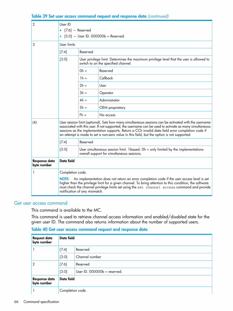
Table 39 Set user access command request and response data (continued)
User ID2• [7:6] — Reserved
• [5:0] — User ID. 000000b = Reserved.
User limits3
Reserved[7:4]
User privilege limit. Determines the maximum privilege level that the user is allowed toswitch to on the specified channel.
[3:0]
Reserved0h =
Callback1h =
User2h =
Operator3h =
Administrator4h =
OEM proprietary5h =
No accessFh =
User session limit (optional). Sets how many simultaneous sessions can be activated with the usernameassociated with this user. If not supported, the username can be used to activate as many simultaneous
(4)
sessions as the implementation supports. Return a CCh invalid data field error completion code ifan attempt is made to set a non-zero value in this field, but the option is not supported.
Reserved[7:4]
User simultaneous session limit. 1-based. 0h = only limited by the implementationsoverall support for simultaneous sessions.
[3:0]
Data fieldResponse databyte number
Completion code.1
NOTE: An implementation does not return an error completion code if the user access level is sethigher than the privilege limit for a given channel. To bring attention to this condition, the softwaremust check the channel privilege limits set using the set channel access command and providenotification of any mismatch.
Get user access commandThis command is available to the MC.This command is used to retrieve channel access information and enabled/disabled state for thegiven user ID. The command also returns information about the number of supported users.
Table 40 Get user access command request and response data
Data fieldRequest databyte number
Reserved[7:4]1
Channel number[3:0]
Reserved[7:6]2
User ID. 000000b = reserved.[3:0]
Data fieldResponse databyte number
Completion code.1
66 Command specification

Table 40 Get user access command request and response data (continued)
NOTE: An implementation does not return an error completion code if the user access level is sethigher than the privilege limit for a given channel. To bring attention to this condition, the softwaremust check the channel privilege limits and provide notification of the mismatch.
Maximum number of user IDs. 1-based. Count includes User 1. A value of 1 indicates only User 1is supported.
2
• [7:6] — Reserved
• [5:0] — Maximum number of user IDs on this channel.
Count of currently enabled user IDs (1-based). A value of 0 indicates that all users, including User1, are disabled. This is equivalent to disabling access to the channel.
3
User ID enable status (for IPMI v2.0 errata 3 and later implementations).[7:6]
User ID enable status unspecified. (For backward compatibility with pre-errata3 implementations. IPMI errata 3 and later implementations should returnthe 01b and 10b responses.)
00b =
User ID enabled via set user password command.01b =
User ID disabled via set user password command.10b =
Reserved.11b =
Count of currently enabled user IDs on this channel which indicates how many user IDslots are presently in use.
[5:0]
Count of user IDs with fixed names, including User 1 (1-based). Fixed names in addition to User 1are required to be associated with sequential user IDs starting from User ID 2.
4
• [7:6] — Reserved
• [5:0] — Count of user IDs with fixed names on this channel.
Channel access5
Reserved[7]
User access available during call-in or callback direct connection.0b =[6]
User access available only during callback connection.1b =
For pre- IPMI v2.0 errata 3 implementations: bits 5:4 are used for determining the count of currentlyenabled user IDs in byte 3. Either bit being set to 1b represents an enabled user ID.For IPMI v2.0 errata 3 and later implementations: the count of enabled User IDs is based on the userIDs that are presently enabled as reflected in byte 3, bits [7:6], user ID enable status.
NOTE: Some pre- IPMI v2.0 errata 3 implementations may automatically clear bits [5:4], and mayalso prevent them from being set, while the user ID is disabled. IPMI v2.0 errata 3 and laterimplementations should not alter bits [5:4] based on whether or not a user ID is enabled.
User disabled for link authentication0b =[5]
User enabled for link authentication1b =
User disabled for IPMI messaging0b =[4]
User enabled for IPMI messaging1b =
User privilege limit for given channel[3:0]
Reserved0h =
Callback1h =
User2h =
Operator3h =
Standard command specification 67

Table 40 Get user access command request and response data (continued)
Administrator4h =
OEM proprietary5h =
No access. This value does not add to, or subtract from, the number ofenabled user IDs
Fh =
Set user name commandThis command is available to the MC.This command adds a new user ID. The names are stored as a logical array within non-volatilestorage associated with the management controller. Names are stored and retrieved using the userID as the index into the logical array. There is no configurable name for User ID 1. User ID 1 isreserved for the null user name, User 1. Null user is not supported.The management controller does not prevent duplicate user names from being enabled for thesame channel. It is the responsibility of configuration software to ensure that duplicate user namesare not enabled simultaneously for the same channel.Having duplicate user names does not cause functional problems with the MC because the MCuses the first username match that it finds. However, it could be confusing to the user if they haveduplicate user names enabled for a given channel, since only the settings for the first encountereduser name would be used by the MC.This command is highly recommended for session-based channels. It is also recommended that theimplementation support multiple users with configurable user names.
Table 41 Set user name command request and response data
Data fieldRequest databyte number
User ID1• [7:6] — Reserved
• [5:0] — User ID. 000000b = reserved. (User ID 1 is permanently associated with User 1, thenull user name).
User name string in ASCII, 16 bytes, max. Strings with fewer than 16 characters are terminated witha null (00h) character and 00h padded to 16 bytes. When the string is read back using the getuser name command, those bytes return as 0’s.
2:17
Data fieldResponse databyte number
Completion code.1
Get user name commandThis command is available to the MC.This command is used to retrieve user name information that was set using the set user namecommand. Configuration software can use this command to retrieve user names.
Table 42 Get user name command request and response data
Data fieldRequest databyte number
User ID1• [7:6] — Reserved
• [5:0] — User ID. 000000b = reserved.
68 Command specification

Table 42 Get user name command request and response data (continued)
Data fieldResponse databyte number
Completion code.1
User name string in ASCII, 16 bytes, max. Strings with fewer than 16 characters are terminated withnull (00h) characters filling in the remaining bytes. MC does not check to see whether string data isprintable or not. Only character that MC interprets is null (00h).
2:17
Set user password commandThis command is available to the MC.This command is used to set and change user passwords and to enable and disable user IDs. Ifno password protection is desired for a given user, the password must be stored as an ASCIInull-string. The management controller firmware forces the remaining fifteen bytes to 00h and storesthe password as sixteen bytes of 00h.The password is stored as a 16-byte or 20-byte (for IPMI v2.0/RMCP+) octet string. All values(0-255) are allowed for every byte. The management controller does not check the format orinterpret values that are passed in with this command.Software is allowed to place additional restrictions on what passwords can be entered, in whichcase it is the responsibility of configuration software and console software to stay in synch withthat definition. For example, remote console software could restrict passwords to the printableASCII character set in order to simplify direct keyboard entry. If this is done, any companionconfiguration utility should ensure that the user does not configure the managed system withnon-printable passwords. Otherwise, it would be possible for the management controller to beconfigured with passwords that could not be entered via the remote console utility.
Table 43 Set user password command request and response data
Data fieldRequest databyte number
User ID1For IPMI v2.0, the MC supports 20-byte passwords for all supported user IDs that have configurablepasswords. The MC maintains an internal tag that indicates whether the password was set as a16-byte or as a 20-byte password.A 16-byte password can be used in algorithms that call for a 20-byte password. In this case, the16-byte password is padded with 0’s to 20- bytes.The test password operation returns the test failed error completion code if an attempt is made totest a password that was stored as a 20-byte password as a 16-byte password (per password sizebit 7), and vice versa. The test password operation can be used to determine whether a passwordhas been stored as 16-bytes or 20-bytes.A password that has been stored as a 20-byte password cannot be used for establishing an IPMIv1.5 session. If it is necessary to configure the same password for both IPMI v2.0 and IPMI v1.5access, it must be set as a 16-byte password.1The password is padded with 0’s as necessary forIPMI v2.0 / RMCP+ use.
Password size[7]
Set 20-byte user password/key.1b =
Set 16-byte user password/key (IPMI v1.5 backward compatible).0b =
Reserved[6]
User ID. 000000b = reserved. (User ID 1 is permanently associated with User 1, the nulluser name).
[5:0]
Reserved[7:2]2
Operation[1:0]
Standard command specification 69

Table 43 Set user password command request and response data (continued)
Disable user00b =
Enable user01b =
Set password10b =
Test password. Compares the password data given in the request with thepresently stored password and returns an OK completion code if there is a
11b =
match. Otherwise, an error completion code is returned. (See the completioncode description in the response data.)
For password size = 16 bytes:
Password data. This is a required, fixed length field when used for the set and test passwordoperations. If the password is entered as an ASCII string, it must be null (00h) terminated and 00h
3:18
padded if the string is shorter than 16 bytes. This field is not needed if the operation is disable useror enable user. If this field is present for those operations, the MC ignores the data.
For password size = 20 bytes:
Password data. This is a required, fixed length field when used for the set- and test passwordoperations. If the password is entered as an ASCII string, it must be null (00h) terminated and 00h
3:22
padded if the string is shorter than 20 bytes. This field is not needed if the operation is disable useror enable user. If this field is present for those operations, the MC ignores the data.
Data fieldResponse databyte number
Completion code. Generic, plus the command-specific completion codes:1
Mandatory. Password test failed. Password size is correct, but the password data doesnot match the stored value.
80h =
Mandatory. Password test failed. Wrong password size was used.81h =1 The same user name can be used with different passwords on different channels. The MC scans user names until it finds
the first one that is enabled for a particular channel. Thus, it is possible for a MC implementation to be configured toallow a 20-byte password on one channel, and a 16-byte password on another channel for the same user name. Thisrequires multiple user entries.
RMCP+ support and payload commandsThis sections list the commands associated with discovering, enabling, and activating payloadsunder IPMI v2.0/RMCP+ as well as updates and additions to IPMI commands to support IPMIv2.0/RMCP+ sessions, authentication, and configuration.
70 Command specification

NOTE: The following commands remain available for payloads if IPMI messaging payload typeis disabled:• Deactivate payload
• Suspend/resume payload encryption (as defined for given payload)
• Get payload activation status
• Get channel payload version command
• Set session privilege level
• Close sessionTable 44 (page 71) defines the payload type numbers and ranges for Payload Type Handles.
Table 44 Payload type numbers
Minor formatversion
Major formatversion
TypeNumber
Standard Payload Types
0h1hIPMI Message0h
0h1hSOL (serial over LAN)1h
Session Setup Payload Types
0h1hRMCP+ Open Session Request10h
0h1hRMCP+ Open Session Response11h
0h1hRAKP Message 112h
0h1hRAKP Message 213h
0h1hRAKP Message 314h
0h1hRAKP Message 415h
Activate payload commandThis command is available to the MC.This command is used for activating and deactivating a payload type under a given IPMI session.The ability to execute this command is determined via the user’s privileges as assigned via the setuser payload access command.The activate payload command may return a port number that is separate from the portnumber for the session that the command was issued under. In this case, the remote console mustestablish a session on the port number that the activate session command returned. Theremote console must then issue the activate payload command on that port number in orderto actually activate the payload. It is possible that the remote console already had a session activeon the given port number. If the privileges associated with that session are sufficient (this is typicallythe case unless the remote console activated the session at a privilege level that was lower thanthe maximum level for the user) the remote console can re-use the existing session and just use theactivate payload command to activate the new payload type.MCs may have limited resources for handling multiple sessions. It is highly recommended that aremote console avoids creating multiple sessions and shares sessions for multiple payloads wheneverpossible.The activate payload command is only accepted over a channel on which payloads can beactivated. For example, the activate payload command cannot be executed from the IPMB.
Standard command specification 71

Table 45 Activate payload command request and response data
Data fieldRequest databyte number
1 • [7:6] — Reserved
• [5:0] — Payload type. IPMI message payloads do not need to be explicitly activated. A payloadthat is required to be launched over a different port than that used to establish the initial IPMIsession is only required to support the IPMI commands needed by the particular payload type.
Payload instance2• [7:4] — Reserved
• [3:0] — Payload instance. 1-based. 0h = reserved.
Auxiliary request data. Additional payload-specific parameters to configure behavior of the payloadwhen it becomes activated. Ignored if no auxiliary data is specified for a given payload type.
3:6
For payload type = SOL:• Byte 1
[7] — Encryption activation. The encryption algorithms specified in this document must beused with authentication. The MC returns an error completion code if an attempt is made toactivate encryption without also activating authentication.
◦
– 1b: Activate payload with encryption. All SOL payload data from the MC is encrypted, ifencryption was negotiated at the time of session activation.
– 0b: Activate payload without encryption. MC sends all SOL payload data unencrypted, ifthat option is allowed. (An SOL configuration parameter allows a system to be configuredto require encryption for all SOL transfers).
◦ [6] — Authentication activation.1b: Activate payload with authentication. All SOL payload data from the MC isauthenticated, if authentication was negotiated at the time of session activation
–
– 0b: Activate payload without authentication. MC sends all SOL payload dataunauthenticated, if that option is allowed. (An SOL configuration parameter allows a systemto be configured to require authentication for all SOL transfers).
◦ [5] — Test mode (optional). Enables DCD and DSR to be manually controlled by the remoteconsole and the reporting of RTS and DTR state via the SOL operation/status byte. This canbe used to facilitate software testing of the 16550 UART interface.– 1b = Activate test mode. If test mode is not supported, bit [0] of the auxiliary response data
will be returned as 0b.– 0b = Deactivate test mode.
◦ [4] — Reserved
◦ [3:2] — Shared serial alert behavior. The following settings determine what happens to serialalerts if IPMI over serial and SOL are sharing the same baseboard serial controller.– 11b: Reserved
– 10b: Serial/modem alerts succeed while SOL active.
– 01b: Serial/modem alerts deferred while SOL active.
– 00b: Serial/modem alerts fail while SOL active.
◦ [1] — SOL startup handshake0b: MC asserts CTS and DCD/DSR to baseboard upon activation.–
– 1b: CTS and DCD/DSR remain deasserted after activation. Remote console must send anSOL payload packet with control field settings to assert CTS and DCD/DSR. (This enables
72 Command specification
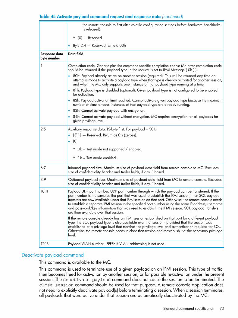
Table 45 Activate payload command request and response data (continued)
the remote console to first alter volatile configuration settings before hardware handshakeis released).
◦ [0] — Reserved
• Byte 2:4 — Reserved, write a 00h
Data fieldResponse databyte number
Completion code. Generic plus the command-specific completion codes: (An error completion codeshould be returned if the payload type in the request is set to IPMI Message ( 0h ) ).
1
• 80h: Payload already active on another session (required). This will be returned any time anattempt is made to activate a payload type when that type is already activated for another session,and when the MC only supports one instance of that payload type running at a time.
• 81h: Payload type is disabled (optional). Given payload type is not configured to be enabledfor activation.
• 82h: Payload activation limit reached. Cannot activate given payload type because the maximumnumber of simultaneous instances of that payload type are already running.
• 83h: Cannot activate payload with encryption.
• 84h: Cannot activate payload without encryption. MC requires encryption for all payloads forgiven privilege level.
Auxiliary response data. LS-byte first. For payload = SOL:2:5• [31:1] — Reserved. Return as 0’s (zeroes).
• [0]
◦ 0b = Test mode not supported / enabled.
◦ 1b = Test mode enabled.
Inbound payload size. Maximum size of payload data field from remote console to MC. Excludessize of confidentiality header and trailer fields, if any. 1-based.
6:7
Outbound payload size. Maximum size of payload data field from MC to remote console. Excludessize of confidentiality header and trailer fields, if any. 1-based.
8:9
Payload UDP port number. UDP port number through which the payload can be transferred. If theport number is the same as the port that was used to establish the IPMI session, then SOL payload
10:11
transfers are now available under that IPMI session on that port. Otherwise, the remote console needsto establish a separate IPMI session to the specified port number using the same IP address, usernameand password/key information that was used to establish the IPMI session. SOL payload transfersare then available over that session.If the remote console already has an IPMI session established on that port for a different payloadtype, the SOL payload type is also available over that session - provided that the session wasestablished at a privilege level that matches the privilege level and authentication required for SOL.Otherwise, the remote console needs to close that session and reestablish it at the necessary privilegelevel.
Payload VLAN number - FFFFh if VLAN addressing is not used.12:13
Deactivate payload commandThis command is available to the MC.This command is used to terminate use of a given payload on an IPMI session. This type of trafficthen becomes freed for activation by another session, or for possible re-activation under the presentsession. The deactivate payload command does not cause the session to be terminated. Theclose session command should be used for that purpose. A remote console application doesnot need to explicitly deactivate payload(s) before terminating a session. When a session terminates,all payloads that were active under that session are automatically deactivated by the MC.
Standard command specification 73

Table 46 Deactivate payload command request and response data
Data fieldRequest databyte number
1 • [7:6] — Reserved
• [5:0] — Payload type.
Payload instance2• [7:4] — Reserved
• [3:0] — Payload instance. 1-based. 0h = reserved.
Payload auxiliary data. Additional parameters to configure behavior of the payload when it becomesdeactivated. Ignored if no auxiliary data is specified for given payload type.
3:6
For payload type = SOL, (no auxiliary data) write as 0000_0000h:
Data fieldResponse databyte number
Completion code. Generic plus the command-specific completion codes: (An error completion codeshould be returned if the payload type in the request is set to “IPMI Message” ( 0h ) ).
1
• 80h: Payload already deactivated.
• 81h: Payload type is disabled (optional). Given payload type is not configured to be enabledfor activation.
Suspend/resume payload encryption commandThis command enables a remote console to control whether payload data from the MC is sentencrypted or not. Since encryption can be a significant burden on software, this command providesa mechanism to allow higher performance by operating without encryption and only activatingencryption when it is required for data confidentiality. The command can also trigger a regenerationof the encryption Initialization Vector and re-initialization of the encryption state machine foralgorithms such as xRC4 that use the same initialization vector for multiple packets.The extent at which this command can control encryption of data from the MC is dependent onthe payload definition. Some payload definitions may use a mix of encrypted and unencryptedpayload data transfers. For example, a payload may implement a ‘request/response’ protocol,where the MC would return an encrypted or unencrypted response based on whether the requestfrom the remote console was encrypted or unencrypted. In this case, the command may only affectdata that is autonomously generated by the MC. Other payload definitions may just use whateverencryption the session was activated with, and offer no ‘run-time’ control of encryption/decryption,while other payload definitions may be ‘stream based’ where it is desirable for the remote consoleto be able to select when payload data is from the MC is encrypted or not.The Suspend/Resume Payload Encryption command is only accepted from the channel that thepayload was activated on.
Table 47 Payload-specific encryption behavior
Payload Type = IPMI Messaging
• Encrypted requests from the remote console will get encrypted responses from the MC.
• The Suspend/Resume Payload Encryption command controls whether asynchronous (unrequested) messages fromthe MC are encrypted or not.
• PET Traps (which are actually separate from IPMI Messaging) are always sent unencrypted.
74 Command specification

Table 47 Payload-specific encryption behavior (continued)
Payload Type = SOL
• The SOL configuration parameters allow configuring the system to require that SOL data be encrypted.
• The MC will transmit SOL payload data according to encryption settings that were selected when the payload wasactivated unless over-ridden by SOL configuration parameters.
• The Suspend/Resume Payload Encryption command controls whether SOL Payload data is encrypted or not.
Table 48 Suspend/resume payload command request and response data
Data fieldIPMIrequestdata bytenumber
[7:6] - reserved1[5:0] - payload type (See Table 13-16, Payload Type Numbers)
Payload Instance2[7:4] - reserved[3:0] - payload instance. 1-based. 0h = reserved.
[7:2] - reserved3[4:0] - Operation• 2h = Regenerate initialization vector. For xRC4 encryption, this causes the MC to reinitialize the xRC4
state machine, reset the data offset, and deliver a new Initialization Vector value in the next encryptedpacket it sends to the remote console. Because of processing delays and potential tasks in progress,the remote console may receive additional packets from the MC that are encrypted using the priorInitialization Vector before getting packets that use the new IV.
• 1h = Resume/Start encryption on all transfers of specified payload data from the MC.
• 0h = Suspend encryption on all transfers of specified payload messages from the MC.
Data fieldIPMIresponsedata bytenumber
Completion Code1Generic plus the following command-specific completion codes:
• 80h: Operation not supported for given payload type.
• 81h: Operation not allowed under present configuration for given payload type.
• 82h: Encryption is not available for session that payload type is active under.
• 83h: The payload instance is not presently active.
Set channel security keys commandThe Set Channel Security Keys command provides a standardized interface for initializing systemunique keys that are used for the pseudo-random number generator key (KR) and the key-generationkey (KG) used for RMCP+. Implementing the ability to set Kr is optional. The command is providedmainly to offer a common interface for BMCs that are not pre-configured with a KR values, or whichmay need their KR values to be restored if they are lost due to a data corruption or firmware update.The command includes a mechanism that allows specified keys to be “locked”. Once locked, thekey value cannot be read back or rewritten via standard IPMI commands. It is possible, however,that a firmware update or re- installation procedure may cause the keys to be cleared or unlocked.Software utilities responsible for MC initial installation and setup should check to see whether keyshave been locked and if not, should initialize them appropriately and lock them.
Standard command specification 75
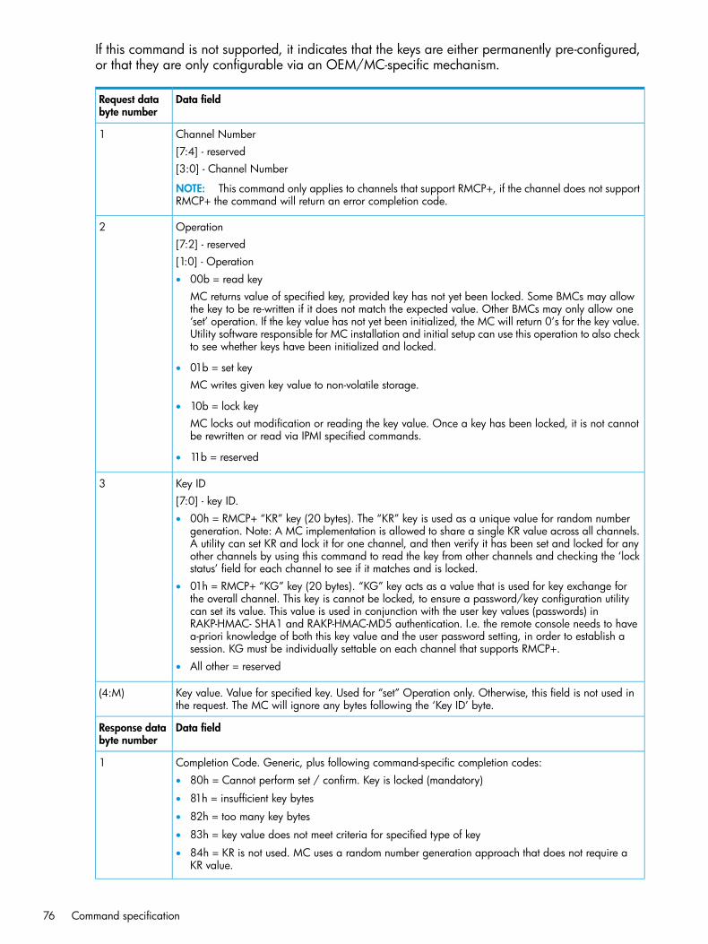
If this command is not supported, it indicates that the keys are either permanently pre-configured,or that they are only configurable via an OEM/MC-specific mechanism.
Data fieldRequest databyte number
Channel Number1[7:4] - reserved[3:0] - Channel Number
NOTE: This command only applies to channels that support RMCP+, if the channel does not supportRMCP+ the command will return an error completion code.
Operation2[7:2] - reserved[1:0] - Operation• 00b = read key
MC returns value of specified key, provided key has not yet been locked. Some BMCs may allowthe key to be re-written if it does not match the expected value. Other BMCs may only allow one‘set’ operation. If the key value has not yet been initialized, the MC will return 0’s for the key value.Utility software responsible for MC installation and initial setup can use this operation to also checkto see whether keys have been initialized and locked.
• 01b = set keyMC writes given key value to non-volatile storage.
• 10b = lock keyMC locks out modification or reading the key value. Once a key has been locked, it is not cannotbe rewritten or read via IPMI specified commands.
• 11b = reserved
Key ID3[7:0] - key ID.• 00h = RMCP+ “KR” key (20 bytes). The “KR” key is used as a unique value for random number
generation. Note: A MC implementation is allowed to share a single KR value across all channels.A utility can set KR and lock it for one channel, and then verify it has been set and locked for anyother channels by using this command to read the key from other channels and checking the ‘lockstatus’ field for each channel to see if it matches and is locked.
• 01h = RMCP+ “KG” key (20 bytes). “KG” key acts as a value that is used for key exchange forthe overall channel. This key is cannot be locked, to ensure a password/key configuration utilitycan set its value. This value is used in conjunction with the user key values (passwords) inRAKP-HMAC- SHA1 and RAKP-HMAC-MD5 authentication. I.e. the remote console needs to havea-priori knowledge of both this key value and the user password setting, in order to establish asession. KG must be individually settable on each channel that supports RMCP+.
• All other = reserved
Key value. Value for specified key. Used for “set” Operation only. Otherwise, this field is not used inthe request. The MC will ignore any bytes following the ‘Key ID’ byte.
(4:M)
Data fieldResponse databyte number
Completion Code. Generic, plus following command-specific completion codes:1• 80h = Cannot perform set / confirm. Key is locked (mandatory)
• 81h = insufficient key bytes
• 82h = too many key bytes
• 83h = key value does not meet criteria for specified type of key
• 84h = KR is not used. MC uses a random number generation approach that does not require aKR value.
76 Command specification

7:2 - reserved.21:0 - lock status• 00b = key is not lockable.
• 01b = key is locked.
• 10b = key is unlocked.
• 11b = reserved
Key value.(3:N)The MC returns the specified key value when the Operation is set to “read key”. Otherwise, the MCreturns no additional bytes past the completion code.
Get system interface capabilities commandThis command can be used to determine whether the SSIF supports multi-part transactions, andwhat size of IPMI messages can be transferred. The Get System Interface Capabilities commandis mandatory for BMCs that implement multi-part writes or reads. Thus, software can assume thatif the Get System Interface Capabilities command is not implemented, the interface only supportssingle-part writes and reads.
Data fieldRequestdata bytenumber
System Interface Type1[7:4] - reserved[3:0] - System Interface Type (For BT use the Get BT Interface Capabilities command)• 0h = SSIF
• 1h = KCS
• 2h = SMIC
• all other = reserved
Data fieldResponsedata bytenumber
Completion Code1
Reserved. Returned as 00h.2
For System Interface Type = SSIF:
[7:6] - Transaction support3• 00b = only single-part reads/writes supported.
• 01b = multi-part reads/writes supported. Start and End transactions only.
• 10b = multi-part reads/writes supported. Start, Middle, and End transactions supported.
• 11b = reserved.
[5:4] - reserved.[3] - PEC support.• 1b = implements PEC. MC will start using PEC in read transactions after it receives any SSIF write
transaction that includes a valid PEC. The MC ceases using PEC if it receives an SSIF write transactionthat does not include PEC.
• 0b = does not support PEC. Note that a MC implementation may reject write transactions that includea PEC byte.
Standard command specification 77

[2:0] - SSIF Version• 000b = version 1 (version defined in this specification).
Input message size in bytes. (1 based.)4Number of bytes of IPMI message data that the MC can accept. This number does not include slave address,SMBus length , PEC, or SMBus CMD bytes, just the IPMI message data. A MC that just supports single-partwrites would return 32 (20h) for this value. A MC that supports multi-part Start and End would return avalue from 33 to 64. A MC that supports multi-part with Middle transactions would return a value from 65to 255.
Output message size in bytes. (1 based.)5Maximum number of bytes of IPMI message data that can be read from the MC. This number does notinclude slave address, SMBus length, PEC, SMBus CMD bytes, special bytes (such as the special bytesfollowing the length byte in the multi -part read middle and end transactions) just the IPMI message data.A MC that just supports single-part reads would return 20h (32) for this value. A MC that supports multi-partStart and End would return a value from 33 to 62 (the reason this is 62 instead of 64 is that there are twospecial bytes after the length byte.) A MC that supports multi-part with Middle transactions would return avalue from 63 to 255.
For System Interface Type = KCS or SMIC
[7:3] - reserved3[2:0] - System Interface Version• 000b = version 1 (conformant with KCS or SMIC interface as defined in this specification).
Input maximum message size in bytes. (1 based.)4Largest number of bytes that can be transferred in a KCS FFh means 255 or more.
Get payload activation status commandThis command is available to the MC.This command returns how many instances of a given payload type are presently activated, andhow many total instances can be activated.
Table 49 Get payload activation status command request and response data
Data fieldRequest databyte number
Payload type number - number of the standard payload type or OEM payload handle from whichto retrieve status.
1
Data fieldResponse databyte number
Completion code1
Instance capacity2
Reserved.[7:4]
Number of instances of a given payload type that can be simultaneously activated onMC. 1-based. 0h = reserved.
[3:0]
Instance 8 is activated.1b =[7]3
Instance 8 is deactivated.0b =
Instance 7 is activated.1b =[6]
Instance 7 is deactivated.0b =
...
Instance 1 is activated.1b =[0]
78 Command specification

Table 49 Get payload activation status command request and response data (continued)
Instance 1 is deactivated.0b =
Instance 16 is activated.1b =[7]4
Instance 16 is deactivated.0b =
Instance 15 is activated.1b =[6]
Instance 15 is deactivated.0b =
...
Instance 9 is activated.1b =[0]
Instance 9 is deactivated.0b =
Get payload instance info commandThis command is available to the MC.This command returns information about a specific instance of a payload type. It is primarily usedby software that may want to negotiate with an application that is presently using the given payloadtype. It accomplishes this by using the session ID returned from this command with the get sessioninfo command to look up the addressing information for the party that activated the payload.The application may then use that information to establish a direct dialog with the application thatpresently owns the payload (this inter-application communication is not defined in the IPMIspecifications).
Table 50 Get payload instance info command request and response data
Data fieldRequest data bytenumber
Payload type number - number of the standard payload type or OEM payload handle from whichto retrieve status.
1
Payload instance. 1-based. 0h = reserved.2
Data fieldResponse databyte number
Completion code. An error completion code should be returned if the payload type in the requestis set to IPMI message ( 0h ) .
1
Session ID - ID of session on which the instance is presently activated. (The managed system sessionID that the MC generated when the session was activated). 00_00_00_00h if the given instance
2:5
is not activated. Remote software can use this information with the get session info commandto identify the remote console that presently is using a given payload type.
Payload-specific information (8-bytes)6:13For payload type = SOL:• Byte 1: Port number, a number representing the system serial port that is being redirected.
1-based. 0h = unspecified. Used when more than one port can be redirected on a system.• Byte 2: 8 = reserved.
Set user payload access commandThis command is available to the MC.This command controls whether the specified user has the ability to activate the specified payloadtype on the given channel. The command uses bitfields to allow a configuration utility to use asingle command to set enable/disable multiple payloads at a time. Standard payloads are setseparately from OEM payload enables. The command would be issued at least once with standard
Standard command specification 79
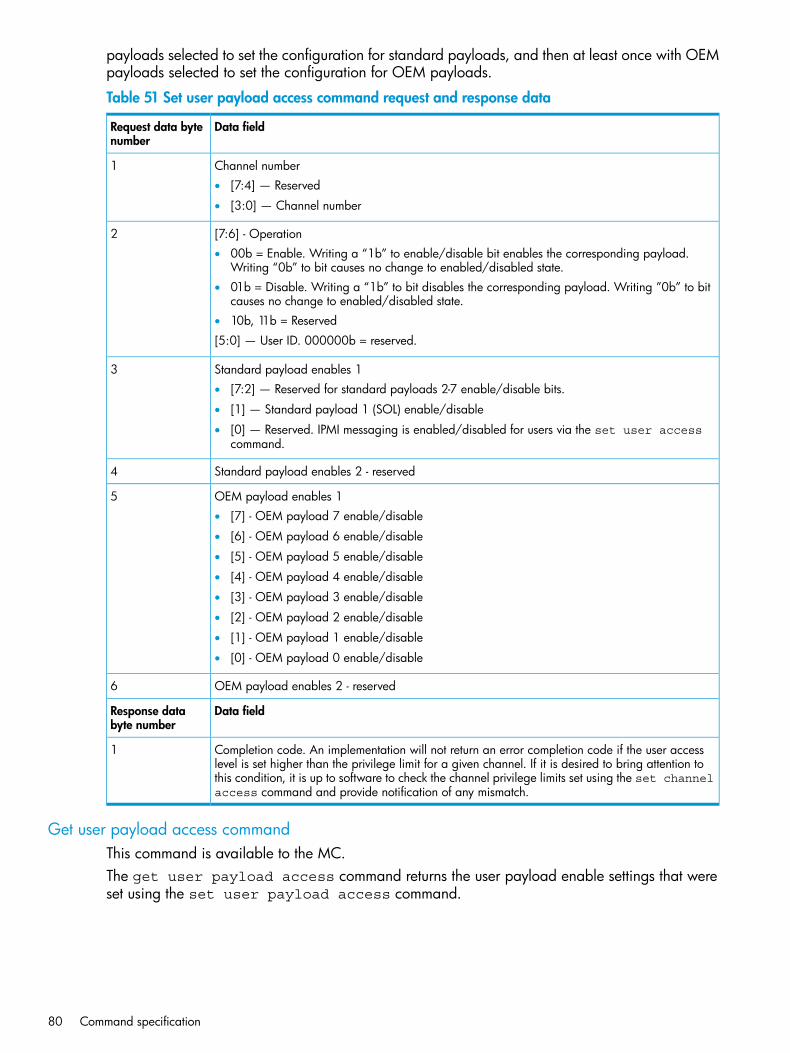
payloads selected to set the configuration for standard payloads, and then at least once with OEMpayloads selected to set the configuration for OEM payloads.
Table 51 Set user payload access command request and response data
Data fieldRequest data bytenumber
Channel number1• [7:4] — Reserved
• [3:0] — Channel number
[7:6] - Operation2• 00b = Enable. Writing a “1b” to enable/disable bit enables the corresponding payload.
Writing “0b” to bit causes no change to enabled/disabled state.• 01b = Disable. Writing a “1b” to bit disables the corresponding payload. Writing ”0b” to bit
causes no change to enabled/disabled state.• 10b, 11b = Reserved
[5:0] — User ID. 000000b = reserved.
Standard payload enables 13• [7:2] — Reserved for standard payloads 2-7 enable/disable bits.
• [1] — Standard payload 1 (SOL) enable/disable
• [0] — Reserved. IPMI messaging is enabled/disabled for users via the set user accesscommand.
Standard payload enables 2 - reserved4
OEM payload enables 15• [7] - OEM payload 7 enable/disable
• [6] - OEM payload 6 enable/disable
• [5] - OEM payload 5 enable/disable
• [4] - OEM payload 4 enable/disable
• [3] - OEM payload 3 enable/disable
• [2] - OEM payload 2 enable/disable
• [1] - OEM payload 1 enable/disable
• [0] - OEM payload 0 enable/disable
OEM payload enables 2 - reserved6
Data fieldResponse databyte number
Completion code. An implementation will not return an error completion code if the user accesslevel is set higher than the privilege limit for a given channel. If it is desired to bring attention to
1
this condition, it is up to software to check the channel privilege limits set using the set channelaccess command and provide notification of any mismatch.
Get user payload access commandThis command is available to the MC.The get user payload access command returns the user payload enable settings that wereset using the set user payload access command.
80 Command specification

Table 52 Get user payload access command request and response data
Data fieldRequest data bytenumber
Channel number1• [7:4] — Reserved
• [3:0] — Channel number
User ID2• [7:6] — Reserved
• [5:0] - User ID. 000000b = reserved
Data fieldResponse databyte number
Completion code1
Standard payload enables 12• [7:2] — Reserved for standard payloads 2-7 enabled/disabled state.
• [1]
◦ 1b = Standard payload 1 enabled (SOL)
◦ 0b = Standard payload 1 disabled
• [0] — Reserved.
Standard payload enables 2 - reserved3
OEM payload enables 1. For each bit: 1b = payload enabled, 0b = payload disabled.4• [7] - OEM payload 7 enabled/disabled
• [6] - OEM payload 6 enabled/disabled
• [5] - OEM payload 5 enabled/disabled
• [4] - OEM payload 4 enabled/disabled
• [3] - OEM payload 3 enabled/disabled
• [2] - OEM payload 2 enabled/disabled
• [1] - OEM payload 1 enabled/disabled
• [0] - OEM payload 0 enabled/disabled
OEM payload enables 2 - reserved5
Get channel payload support commandThis command is available to the MC.This command enables local and remote console software to determine what payloads are enabledon the given MC. The command returns a bitfield indicating which payload type numbers can beactivated on the given channel.
Table 53 Get channel payload support command request and response data
Data fieldRequest data bytenumber
Channel number1• [7:4] — Reserved
• [3:0] — Channel number
Data fieldResponse databyte number
Standard command specification 81

Table 53 Get channel payload support command request and response data (continued)
Completion code1
2 • [7] = Standard payload type #7 supported
• ...
• [0] = Standard payload type #0 supported
3 • [7] = Standard payload type #15 (0Fh) supported
• ...
• [0] = Standard payload type #8 supported
4 • [7] = Session setup payload type #7 supported
• ...
• [0] = Session setup payload type #0 supported
5 • [7] = Session setup payload type #15 (0Fh) supported
• ...
• [0] = Session setup payload type #8 supported
6 • [7] = Payload type 27h (OEM7) used
• ...
• [0] = Payload type 20h (OEM0) used
7 • [7] = Payload type 2Fh (OEM15) used
• ...
• [0] = Payload type 28h (OEM8) used
Reserved. Return as 0000h8:9
Get channel payload version commandThis command is available to the MC.This command returns version information for the given payload type. The version number hasmajor and minor parts. The major part of the version should only increment when there aresignificant changes to the payload format, commands, or payload-specific protocols that breakbackward compatibility with earlier versions. The minor part of the version increments when thereare extensions to the payload format that are significant but are backwards compatible with earlierversions under the same major version number. An example of a major change would be a changeto the payload activation process that would prevent earlier applications from activating the givenpayload type. An example of a minor format version change would be the definition of commandsfor new functions that did not exist under the previous format, but if unused, do not interfere withthe operation of older applications.
Table 54 Get channel payload version command request and response data
Data fieldRequest data bytenumber
Channel number1• [7:4] — Reserved
• [3:0] — Channel number
Payload type number/payload type handle - number of the standard payload type or OEM payloadhandle for which to retrieve status. See Table 44 (page 71).
2
82 Command specification

Table 54 Get channel payload version command request and response data (continued)
Data fieldResponse databyte number
Completion code. Generic plus command-specific completion code: 80h — Payload type notavailable on given channel.
1
Format version2• [7:4] - Major format version. BCD encoded (0 to 9).
• [3:0] - Minor format version. BCD encoded (0 to 9). Software should present version data tothe user in the format “major.minor”. For example, 10h —>1.0.
The format version for the SOL payload implemented per this specification is 1.0 (10h).
IPMI LAN Device CommandsThis section defines the configuration and control commands that are specific to LAN channels.None of the commands in the following table are required unless a LAN channel is implemented.See Table 126 (page 160) for the specification of the Network Function and Command (CMD)values and privilege levels for these commands.
Set LAN configuration parameters commandThis command is used for setting parameters such as the network addressing information requiredfro IPMI LAN-operation.
Table 55 Set LAN configuration parameters command request and response data
Data fieldRequest data bytenumber
Channel number1• [7:4] — Reserved
• [3:0] — Channel number
Parameter selector2
Configuration parameter data, per the table.3:N
Data fieldResponse databyte number
Completion code.1• 80h = parameter not supported.
• 81h = attempt to set the ‘set in progress’ value (in parameter #0) when not in the ‘set complete’state. (This completion code provides a way to recognize that another party has already‘claimed’ the parameters.)
• 82h = attempt to write read-only parameter.
• 83h = attempt to read write-only parameter.
Get LAN configuration parameters commandThis command is used for retrieving the configuration parameters from the set LANconfiguration parameters command.
Standard command specification 83

Table 56 Get LAN configuration parameters command request and response data
Data fieldRequest data bytenumber
[7]1• 0b = Get parameter
• 1b = Get parameter revision only
[6:4] - Reserved[3:0] - Channel number
Parameter selector2
Set Selector. Selects a given set of parameters under a given Parameter selector value. 00hif parameter doesn’t use a Set Selector.
3
Block Selector (00h if parameter does not require a block number)4
Data fieldResponse databyte number
Completion Code.1Generic codes, plus following command-specific completion code(s):80h = parameter not supported.
[7:0] - Parameter revision.2Format: MSN = Present revision. LSN = Oldest revision with which the parameter is backwardcompatible. 11h for parameters in this specification.
The following data bytes are not returned when the ‘get parameter revision only’ bit is 1b.
Configuration parameter data, per Table 57 (page 84). If the rollback feature is implemented,the MC makes a copy of the existing parameters when the ‘set in progress’ state becomes
3:N
asserted (See the Set In Progress parameter #0). While the ‘set in progress’ state is active,the MC will return data from this copy of the parameters, plus any uncommitted changesthat were made to the data. Otherwise, the MC returns parameter data from non-volatilestorage.
Table 57 LAN configuration parameters
Parameter Data (non-volatile unless otherwise noted)1#Parameter
data 1 - This parameter is used to indicate when any of the following parametersare being updated, and when the updates are completed. The bit is primarily
0Set In Progress(volatile)
provided to alert software than some other software or utility is in the process ofmaking changes to the data. An implementation can also elect to provide a‘rollback’ feature that uses this information to decide whether to ‘roll back’ to theprevious configuration information, or to accept the configuration change.If used, the roll back shall restore all parameters to their previous state. Otherwise,the change shall take effect when the write occurs.[7:2] - reserved[1:0] -• 00b = set complete. If a system reset or transition to powered down state occurs
while ‘set in progress’ is active, the MC will go to the ‘set complete’ state. Ifrollback is implemented, going directly to ‘set complete’ without first doing a‘commit write’ will cause any pending write data to be discarded.
• 01b = set in progress. This flag indicates that some utility or other software ispresently doing writes to parameter data. It is a notification flag only, it is nota resource lock. The MC does not provide any interlock mechanism that wouldprevent other software from writing parameter data while.
• 10b = commit write (optional). This is only used if a rollback is implemented.The MC will save the data that has been written since the last time the ‘set in
84 Command specification
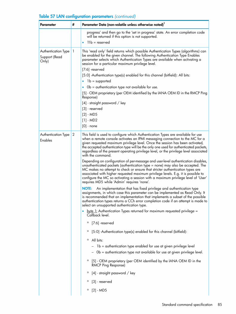
Table 57 LAN configuration parameters (continued)
Parameter Data (non-volatile unless otherwise noted)1#Parameter
progress’ and then go to the ‘set in progress’ state. An error completion codewill be returned if this option is not supported.
• 11b = reserved
This ‘read only’ field returns which possible Authentication Types (algorithms) canbe enabled for the given channel. The following Authentication Type Enables
1Authentication TypeSupport (ReadOnly) parameter selects which Authentication Types are available when activating a
session for a particular maximum privilege level.[7:6] -reserved[5:0] -Authentication type(s) enabled for this channel (bitfield): All bits:• 1b = supported
• 0b = authentication type not available for use.
[5] - OEM proprietary (per OEM identified by the IANA OEM ID in the RMCP PingResponse)[4] - straight password / key[3] - reserved[2] - MD5[1] - MD2[0] - none
This field is used to configure which Authentication Types are available for usewhen a remote console activates an IPMI messaging connection to the MC for a
2Authentication TypeEnables
given requested maximum privilege level. Once the session has been activated,the accepted authentication type will be the only one used for authenticated packets,regardless of the present operating privilege level, or the privilege level associatedwith the command.Depending on configuration of per-message and user-level authentication disables,unauthenticated packets (authentication type = none) may also be accepted. TheMC makes no attempt to check or ensure that stricter authentication types areassociated with higher requested maximum privilege levels. E.g. it is possible toconfigure the MC so activating a session with a maximum privilege level of ‘User’requires MD5 while ‘Admin’ requires ‘none’.
NOTE: An implementation that has fixed privilege and authentication typeassignments, in which case this parameter can be implemented as Read Only. Itis recommended that an implementation that implements a subset of the possibleauthentication types returns a CCh error completion code if an attempt is made toselect an unsupported authentication type.• byte 1: Authentication Types returned for maximum requested privilege =
Callback level.
◦ [7:6] -reserved
◦ [5:0] -Authentication type(s) enabled for this channel (bitfield):
◦ All bits:– 1b = authentication type enabled for use at given privilege level
– 0b = authentication type not available for use at given privilege level.
◦ [5] - OEM proprietary (per OEM identified by the IANA OEM ID in theRMCP Ping Response)
◦ [4] - straight password / key
◦ [3] - reserved
◦ [2] - MD5
Standard command specification 85

Table 57 LAN configuration parameters (continued)
Parameter Data (non-volatile unless otherwise noted)1#Parameter
◦ [1] - MD2
◦ [0] - none
• byte 2: Authentication Type(s) for maximum privilege = User level(format follows byte 1)
• byte 3: Authentication Type (s) for maximum privilege = Operator level(format follows byte 1)
• byte 4: Authentication Type (s) for maximum privilege = Administrator level(format follows byte 1)
• byte 5: Authentication Type (s) for maximum privilege = OEM level(format follows byte 1)
data 1:4 - IP Address3IP AddressMS-byte first.
data 14IP Address Source[7:4] -reserved[3:0] -address source• 0h = unspecified
• 1h = static address (manually configured)
• 2h = address obtained by MC running DHCP
• 3h = address loaded by BIOS or system software
• 4h = address obtained by MC running other address assignment protocol
data 1:6 - MAC Address for messages transmitted from MC.5MAC AddressMS-byte first. An implementation can either allow this parameter to be settable, orit can be implemented as Read Only.
(can be Read Only)
data 1:4 - Subnet Mask. MS-byte first.6Subnet Mask
7IPv4 HeaderParameters
• data 1 - Time-to-live. 1-based. (Default = 40h)Value for time-to-live parameter in IP Header for RMCP packets and PET Trapstransmitted from this channel.
• data 2
◦ [7:5] - Flags. Sets value of bit 1 in the Flags field in the IP Header for packetstransmitted by this channel. (Default = 010b “don’t fragment”)
◦ [4:0] - reserved
• data 3
◦ [7:5] - Precedence (Default = 000b)
◦ [4:1] - Type of Service (Default = 1000b, “minimize delay”) [0] - reserved
data 1:2 - Primary RMCP Port Number, LSByte first.8Primary RMCP PortDefault = 26Fh (RMCP ‘Aux Bus Shunt’ port)Number (optional)
data 1:2 - Secondary Port Number, LSByte first.9Secondary RMCPPort Default = 298h (RMCP ‘Secure Aux Bus’ port)Number (optional)
86 Command specification

Table 57 LAN configuration parameters (continued)
Parameter Data (non-volatile unless otherwise noted)1#Parameter
data 1 - MC-generated ARP control. Note: the individual capabilities forMC-generated ARP responses and MC-generated Gratuitous ARPs are individually
10MC-generated ARPcontrol
optional. The MC should return an error completion code if an attempt is made toenable an unsupported capability.(optional2)
[7:2] - reserved[1] -• 1b = enable MC-generated ARP responses
• 0b = disable MC-generated ARP responses
[0] -• 1b = enable MC-generated Gratuitous ARPs
• 0b = disable MC-generated Gratuitous ARPs
data 1 -11Gratuitous ARPinterval (optional) • Gratuitous ARP interval
• Gratuitous ARP interval in 500 millisecond increments. 0-based. Interval accuracyis +/- 10%.
• If this configuration parameter is not implemented, gratuitous ARPs shall beissued at a rate of once every 2 seconds.
data 1:4 - IP Address12Default GatewayMS-byte first. This is the address of the gateway (router) used when the MC sendsa message or alert to a party on a different subnet than the one the MC is on.
Address
data 1:6 - MAC Address. MS-byte first.13Default GatewayMAC Address
data 1:4 - IP Address14Backup GatewayMS-byte first. This is the address of an alternate gateway (router) that can beselected when a sending a LAN Alert.
Address
data 1:6 - MAC Address. MS-byte first.15Backup GatewayMAC Address
data 1:18 - Community String16Community StringDefault = ‘public’. Used to fill in the ‘Community String’ field in a PET Trap. Thisstring may optionally be used to hold a vendor-specific string that is used to providethe network name identity of the system that generated the event. Printable ASCIIstring-. If a full 18 non-null characters are provided, the last character does notneed to be a null. 18 characters must be written when setting this parameter, and18 will be returned when this parameter is read.The null character, and any following characters, will be ignored when theCommunity String parameter is placed into the PET. The MC will return whatevercharacters were written. In other words, it will not set bytes following the null toany particular value.
data 1 - Number of LAN Alert Destinations supported on this channel. (Read Only).At least one set of non-volatile destination information is required if LAN alerting
17Number ofDestinations
is supported. Additional non-volatile destination parameters can optionally be(Read Only)provided for supporting an alert ‘call down’ list policy. A maximum of fifteen (1hto Fh) non-volatile destinations are supported in this specification. Destination 0 isalways present as a volatile destination that is used with the Alert Immediatecommand.[7:4] - reserved.[3:0] - Number LAN Destinations. A count of 0h indicates LAN Alerting is notsupported.
Standard command specification 87

Table 57 LAN configuration parameters (continued)
Parameter Data (non-volatile unless otherwise noted)1#Parameter
Sets the type of LAN Alert associated with the given destination. This parameteris not present if the Number of Destinations parameter is 0.
18Destination Type(volatile /non-volatile - seedescription)
• data 1 - Set Selector = Destination selector, 0 based.
[7:4] -reserved◦◦ [3:0] -Destination selector. Destination 0 is always present as a volatile
destination that is used with the Alert Immediate command.
• data 2 - Destination Type
◦ [7] - Alert Acknowledge.– 0b = Unacknowledged. Alert is assumed successful if transmission occurs
without error. This value is also used with Callback numbers.– 1b = Acknowledged. Alert is assumed successful only if acknowledged
is returned. Note, some alert types, such as Dial Page, do not supportan acknowledge.
◦ [6:3] -reserved
◦ [2:0] -Destination Type– 000b = PET Trap destination
– 001b - 101b = reserved
– 110b = OEM 1
– 111b = OEM 2
• data 3 - Alert Acknowledge Timeout / Retry Interval, in seconds, 0-based (i.e.minimum timeout = 1 second).This value sets the timeout waiting for an acknowledge, or the time betweenautomatic retries depending on whether the alert is acknowledge or not.Recommended factory default = 3 seconds. Value is ignored if alert type doesnot support acknowledge, or if the Alert Acknowledge bit (above) is 0b.
• data 4 - Retries
◦ [7:4] - Reserved
◦ [3] - Reserved
◦ [2:0] - Number of times to retry alert to given destination. 0 = no retries(alert is only sent once). If the alert is acknowledged (Alert Acknowledge bit= 1b) the alert will only be retried if a timeout occurs waiting for theacknowledge. Otherwise, this value selects the number of times anunacknowledged alert will be sent out. The timeout interval or time betweenretries is set by the Alert Acknowledge Timeout / Retry Interval value (byte3 of this parameter).
88 Command specification

Table 57 LAN configuration parameters (continued)
Parameter Data (non-volatile unless otherwise noted)1#Parameter
Sets/Gets the list of IP addresses that a LAN alert can be sent to. This parameteris not present if the Number of Destinations parameter is 0.
19DestinationAddresses
• data 1 - Set Selector = Destination Selector.
[7:4] -reserved◦◦ [3:0] -Destination selector. Destination 0 is always present as a volatile
destination that is used with the Alert Immediate command.
• data 2 - Address Format
◦ [7:4] - Address Format.0h = IPv4 IP Address followed by DIX Ethernet/802.3 MAC Address
◦ [3:0] - Reserved
For Address Format = 0h:
• data 3 - Gateway selector
[7:1] - Reserved◦◦ [0] -
– 0b = use default gateway
– 1b = use backup gateway
• data 4:7 - Alerting IP Address (MS-byte first)
• data 8:13 - Alerting MAC Address (MS-byte first)
Following parameters are introduced with IPMI v2.0 / RMCP+VLAN configuration can be used with IPMI v1.5 and IPMI v2.0sessions. Parameters labeled “RMCP+” arespecific to IPMI v2.0 implementations that implement IPMI v2.0 / RMCP+ sessions.
20802.1q VLAN ID(12-bit)
• data 1[7:0] - Least significant 8-bits of the VLAN ID. 00h if VLAN ID not used.
• data 2
◦ [7] - VLAN ID enable.– 0b = disabled
– 1b = enabled.If enabled, the MC will only accept packets for this channel if they have802.1q fields and their VLAN ID matches the VLAN ID value given inthis parameter.
◦ [6:4] - Reserved
◦ [3:0] - Most significant four bits of the VLAN ID
data 121802.1q VLANPriority [7:3] - Reserved
[2:0] - Value for Priority field of 802.1q fields. Ignored when VLAN ID enable is0b (disabled) - See 802.1q VLAN ID parameter, above. Setting is networkdependent. By default, this should be set to 000b.
This parameter provides a count of the number (16 max.) of Cipher Suites availableto be enabled for use with IPMI Messaging on the given channel.
22RMCP+ MessagingCipher Suite EntrySupport Software can find out what security algorithms are associated with given Cipher
Suite ID by using the Get Channel Cipher Suites command. In addition, there are(Read Only)
Standard command specification 89

Table 57 LAN configuration parameters (continued)
Parameter Data (non-volatile unless otherwise noted)1#Parameter
Cipher Suite IDs assigned for standard Cipher Suites (see Table 22-19, CipherSuite IDs)data 1[7:5] - reserved[4:0] - Cipher Suite Entry count. Number of Cipher Suite entries, 1-based, 10hmax.
This parameter contains zero to sixteen (16) bytes of Cipher Suite IDs for CipherSuites that can be used for establishing an IPMI messaging session with the MC.The number of Cipher Suites that are supported is given in the preceding parameter.
23RMCP+ MessagingCipher Suite Entries(Read Only)
• data 1 - Reserved
• data 2 - Cipher Suite ID entry A. data 3 - Cipher Suite ID entry B.
• ...
• data 17 - Cipher Suite ID entry P.
This parameter allows the configuration of which privilege levels are associatedwith each Cipher Suite. The total number of nibbles supported (zero to sixteen)matches the number of fixed Cipher Suite IDs.
24RMCP+ MessagingCipher SuitePrivilege Levels
• data 1 - Reserved
• data 2 - Maximum Privilege Level for 1st and 2nd Cipher Suites
◦ [7:4] - Maximum Privilege Level for 2nd Cipher Suite
◦ [3:0] - Maximum Privilege Level for 1st Cipher Suite– 0h = Unspecified (given Cipher Suite is unused)
– 1h = Callback level
– 2h = User level
– 3h = Operator level
– 4h = Administrator level
– 5h = OEM Proprietary level
• data 3 - Maximum Privilege Level for 3rd and 4th Cipher Suites data 4 -Maximum Privilege Level for 5th and 6th Cipher Suites
• …
• data 9 - Maximum Privilege Level for 15th and 16th Cipher Suites
Sets/Gets the VLAN IDs (if any) addresses that a LAN alert can be sent to. Thisparameter is not present if the Number of Destinations parameter is 0, or if the
25Destination AddressVLAN TAGs
implementation does not support the use of VLAN IDs for alerts. Otherwise, thenumber of VLAN TAG entries matches the number of Alert Destinations.(can be READ
ONLY, seedescription) An implementation may only be able to send alerts using the same VLAN TAG
configuration as specified by parameters 20 and 21, in which case this parameteris allowed to be READ ONLY, where data 3-4 reflects the settings of parameters20 and 21, and data 2 [7:4] indicates that VLAN TAGs are being used for alerts.If the implementation does support configurable VLAN TAGs for alert destinations,
90 Command specification

Table 57 LAN configuration parameters (continued)
Parameter Data (non-volatile unless otherwise noted)1#Parameter
it must support configuring unique TAG information for all destinations on the givenchannel.
• data 1 - Set Selector = Destination Selector.
[7:4] -reserved◦◦ [3:0] -Destination selector. Destination 0 is always present as a volatile
destination that is used with the Alert Immediate command.
• data 2 - Address Format
◦ [7:4] - Address Format.– 0h = VLAN ID not used with this destination
– 1h = 802.1q VLAN TAG
◦ [3:0] - Reserved
For Address Format = 1h:
• data 3:-4 - VLAN TAG
◦ [7:0] - VLAN ID, least-significant byte
◦ [11:8] - VLAN ID, most-significant nibble
◦ [12] - CFI (Canonical Format Indicator. Set to 0b) [15:13] - User priority(000b, typical)
Sets/Gets the Bad Password Threshold. If implemented and non-zero, this valuedetermines the number of sequential bad passwords that will be allowed to be
26Bad PasswordThreshold (optional)
entered for the identified user before the user is automatically disabled from accesson the channel.For example, a value of 3 indicates that 3 sequential attempts are allowed for thegiven username on the particular channel. If the password for the third attempt isnot correct, the user will be disabled for the channel. If this value is zero (00h)then there is no limit on bad passwords.The effect of the disable is the same as if a Set User Access command were usedto remove the user's access from the channel.Bad password attempts are tracked according to individual username on a perchannel basis. (Thus, a given username may be disabled on one channel, but stillenabled on another) Bad password attempts are not counted if integrity check orother session parameters, such as session ID, sequence number, etc. are invalid.That is, bad password attempts are not counted if there are any other errors thatwould have caused the login attempt to be rejected even if the password wasvalid. The count of bad password attempts is retained as long as the MC remainspowered and is not reinitialized.Counting automatically starts over (is reset) under any one of the followingconditions:
• A valid password is received on any of the allowed attempt
• The Attempt Count Reset Interval expires
• The user is re-enabled using the Set User Access command
• The user is automatically re-enabled when the User Lockout Interval expires.
• The Bad Password Threshold parameter value is re-written or changed
Standard command specification 91

Table 57 LAN configuration parameters (continued)
Parameter Data (non-volatile unless otherwise noted)1#Parameter
The Set User Access command is used to re-enable the user for the Channel.
• byte 1
[7:1] - reserved◦◦ [0] -
– 0b = do not generate an event message when the user is disabled.
– 1b = generate a Session Audit sensor "Invalid password disable" eventmessage. byte 2
◦ 7:0 - Bad Password Threshold number.
• byte 3:4
◦ 15:0 - Attempt Count Reset Interval. The interval, in tens of seconds, forwhich the accumulated count of bad password attempts is retained beforebeing automatically reset to zero. The interval starts with the most recentbad password attempt for the given username on the channel. This intervalis allowed to reset if a MC power cycles or re-initialization occurs while theinterval is being counted.0000h = Attempt Count Reset Interval is disabled. The count of bad passwordattempts is retained as long as the MC remains powered and is notreinitialized.
• byte 5:6
◦ 15:0 - User Lockout Interval. The interval, in tens of seconds, that the userwill remain disabled after being disabled because the Bad PasswordThreshold number was reached. The user is automatically re-enabled whenthe interval expires. Note that this requires the MC implementation to trackthat the user was disabled because of a Bad Password Threshold. This intervalis allowed to be restarted if a MC power cycle or re-initialization occurswhile the interval is being counted. Note that this requires an internalnon-volatile setting to be maintained that tracks when a particular user hasbeen temporarily disabled due to the Bad Password Threshold. This isrequired to distinguish a user that was disabled automatically from a userthat is intentionally disabled using the Set User Access command.0000h = User Lockout Interval is disabled. If a user was automaticallydisabled due to the Bad Password threshold, the user will remain disableduntil re-enabled via the Set User Access command.
This range is available for special OEM configuration parameters. The OEM isidentified according to the Manufacturer ID field returned by the Get Device IDcommand.
192:255
OEM Parameters
1 Choice of system manufacturing defaults is left to the system manufacturer unless otherwise specified.2 This configuration parameter must be supported if the controller autonomously issues gratuitous ARPs or ARP responses.
SOL commands
Set SOL configuration parameters commandThis command is available to the MC.This command is used for setting parameters such as the network addressing information requiredfor SOL payload operation. Parameters can be volatile or non-volatile.
92 Command specification

Table 58 Set SOL configuration parameters command request and response data
Data fieldRequest data bytenumber
1 • [7:4] — Reserved
• [3:0] — Channel number
Parameter selector2
Configuration parameter data. See Table 60 (page 94).3:N
Data fieldResponse databyte number
Completion code.1• 80h = Parameter not supported.
• 81h = Attempt to set the set in progress value (in parameter #0) when not in the set completestate. (This completion code provides a way to recognize that another party has already“claimed” the parameters).
• 82h = Attempt to write read-only parameter.
• 83h = Attempt to read write-only parameter.
Get SOL configuration parameters commandThis command is available to the MC.This command is used for retrieving the configuration parameters from the set solconfiguration parameters command.
Table 59 Get SOL configuration parameters command request and response data
Data fieldRequest data bytenumber
1 • [7]
0b = Get parameter◦◦ 1b = Get parameter revision only
• [6:4] — Reserved
• [3:0] — Channel number
Parameter selector2
Set selector. Selects a given set of parameters under a given parameter selector value. 00h ifparameter does not use a set selector.
3
Block selector (00h if parameter does not require a block number).4
Data fieldResponse databyte number
Completion code. Generic codes, plus command-specific completion code: 80h = parameter notsupported.
1
[7:0] - Parameter revision. Format: MSN = present revision. LSN = oldest revision parameter inwhich it is backward compatible. 11h for parameters in this specification.
The following data byte is not returned when the get parameter revision only bit is 1b.
Configuration parameter data, per Table 60: “SOL configuration parameters” (page 94) If therollback feature is implemented, the MC makes a copy of the existing parameters when the set in
3:N
progress state becomes asserted. (See the set in progress parameter #0). While the set in progressstate is active, the MC returns data from this copy of the parameters, plus any uncommitted changesthat were made to the data. Otherwise, the MC returns parameter data from non-volatile storage.
Standard command specification 93

Table 60 SOL configuration parameters
Parameter Data (non-volatile unless otherwise noted)1#Parameter
Data 1 - This parameter is used to indicate when any of the following parametersare being updated, and when the updates are completed. The bit is primarily
0Set In Progress (volatile)
provided to alert software that some other software or utility is in the process ofmaking changes to the data.An implementation can also elect to provide a rollback feature that uses thisinformation to decide whether to roll back to the previous configurationinformation, or to accept the configuration change.If used, the roll back restores all parameters to their previous state. Otherwise,the change takes effect when the write occurs.
Reserved[7:2]
Set complete. If a system reset or transition to powereddown state occurs while set in progress is active, the MC
00b =[1:0]
goes to the set complete state. If rollback is implemented,going directly to set complete without first doing a commitwrite causes any pending write data to be discarded.
Set in progress. This flag indicates that some utility orother software is presently doing writes to parameter data.
01b =
It is a notification flag only, it is not a resource lock. TheMC does not provide any interlock mechanism that wouldprevent other software from writing parameter data.
Commit write (optional). This is only used if a rollback isimplemented. The MC saves the data that has been written
10b =
since the last time it was set in progress and then goes tothe set in progress state. An error completion code willbe returned if this option is not supported.
Reserved11b =
Byte 1:1SOL enable
Reserved[7:1]
SOL enable. This controls whether the SOL payload typecan be activated. Whether an SOL stream can be
[0]
established is also dependent on the access mode andauthentication settings for the corresponding LAN channel.The enabled/disabled state and access mode settings forthe serial/modem channel have no effect on SOL.
Enable SOL payload1b =
Disable SOL payload0b =
Byte 1: SOL authentication enable2SOL authentication
Force SOL payload encryption[7]
Force encryption. If the cipher suite for the session supportsencryption, this setting forces the use of encryption for allSOL payload data.
1b:
Encryption controlled by remote console. Whether SOLpackets are encrypted or not is selected by the remote
0b:
console at the time the payload is activated (using theactivate payload command) and can be changedduring operation via the suspend/resume payloadencryption command.
Force SOL payload authentication[6]
94 Command specification

Table 60 SOL configuration parameters (continued)
Parameter Data (non-volatile unless otherwise noted)1#Parameter
Force authentication. If the cipher suite for the sessionsupports authentication, this setting forces the use ofauthentication on all SOL payload data.
1b:
Authentication controlled by remote software. For thestandard cipher suites, if encryption is used then
0b:
authentication must also be used. Therefore, whileencryption is being used, software is not be able to selectusing unauthenticated payloads.
Reserved[5:4]
SOL privilege level. Sets the minimum operating privilege level that isrequired to be able to activate SOL using the activate payloadcommand.
[3:0]
Reserved0h:
Reserved1h:
User level2h:
Operator level3h:
Administrator level4h:
OEM proprietary level5h:
ReservedAll other :
3Character accumulateinterval & character sendthreshold
• Byte 1: Character accumulate interval in 5 ms increments. 1-based. This setsthe typical amount of time that the MC waits before transmitting a partial SOLcharacter data packet. (Where a partial packet is defined as a packet thathas fewer characters to transmit than the number of characters specified bythe Send threshold parameter (see below). A packet is not sent.00h = reserved
• Byte 2: Character send threshold. 1-based. The MC automatically sends anSOL character data packet containing this number of characters as soon asthis number of characters (or greater) has been accepted from the baseboardserial controller into the MC. This provides a mechanism to tune the buffer toreduce latency to when the first characters are received after an idle interval.In the degenerate case, setting this value to 1 would cause the MC to senda packet as soon as the first character was received.This can be useful if the character accumulate interval is large. If the MC iswaiting for an acknowledge from the previous packet, it ignores this thresholdand continues to collect data until it has a full packet’s worth.
4SOL retry • Byte 1: Retry count
[7:3] - Reserved◦◦ [2:0] - Retry count. 1-based. 0 = no retries after packet is transmitted.
Packet is dropped if no ACK/NACK received by the time retries expire.
• Byte 2: Retry interval. 1-based. Retry interval in 10 ms increments. Sets thetime that the MC waits before the first retry and the time between retries whensending SOL packets to the remote console.
◦ 00h: Retries sent back-to-back
This configuration parameter is not supported if the implementation does nothave a MC serial controller that can be potentially configured.
5SOL non-volatile bit rate(non-volatile)
Serial communication with the MC when SOL is activated always occurs using8 bits/character, no parity, 1 stop bit, and RTS/CTS (hardware) flow control.
Standard command specification 95

Table 60 SOL configuration parameters (continued)
Parameter Data (non-volatile unless otherwise noted)1#Parameter
NOTE: If SOL is enabled for multiple LAN channels, the MC uses the serialcommunication settings for the channel over which the activate sol commandwas initially received. The settings for other channels are ignored.Data 1
Reserved[7:4]
Bit rate. 1-5h = reserved. Support for bit rates other than 19.2 kbps isoptional. The MC must return an error completion if a requested bit
[3:0]
rate is not supported. It is recommended that the parameter out-of-range(C9h) code be used for this situation.
Use setting presently configured for IPMI over serialchannel. The setting is used even if the access mode for
0h =
the serial channel is set to disabled. IPMI specificationcan allow more than one serial channel. If serial portsharing is not implemented, this value is reserved. 6h:9600 bps.
19.2 kbps7h =
38.4 kbps8h =
57.6 kbps9h =
115.2 kbpsAh =
ReservedAll other =
Set volatile version of SOL serial settings. Data follows that for the SOL non-volatilebit rate parameter.
6SOL volatile bit rate(volatile)
This parameter indicates which IPMI channel is being used for the communicationparameters (such as IP address, MAC address) for the SOL payload. Typically,
7SOL payload channel(optional, read only)
these parameters come from the same channel that the activate payloadcommand for SOL was accepted.
This parameter is read/write when the implementation allows the port numberover which the SOL payload can be activated to be configurable. Otherwise, itis a read only parameter.
8SOL payload port number(read only or read/write)
Data 1:2 - Primary RMCP port number, LS byte first.
This range is available for special OEM configuration parameters. The OEM isidentified according to the manufacturer ID field returned by the get deviceid command.
192:255OEM parameters
1 Choice of system manufacturing defaults is left to the system manufacturer unless otherwise specified.
MC watchdog timer commandsThe MC implements a standardized watchdog timer that can be used for a number of systemtimeout functions by system management software or by the BIOS. Setting a timeout value of 0allows the selected timeout action to occur immediately. This provides a standardized means fordevices on the IPMB, such as remote management cards, to perform emergency recovery actions.
Watchdog timer actionsThe following actions are available on expiration of the watchdog timer:
• System reset
• System power off
96 Command specification

• System power cycle
• Pre-timeout interrupt (optional)The system reset on timeout, system power off on timeout, and system power cycle on timeoutaction selections are mutually exclusive. The watchdog timer is stopped whenever the system ispowered-down. A command must be sent to start the timer after the system powers up.
Watchdog timer use field and expiration flagsThe watchdog timer provides a timer use field that indicates the current use assigned to the watchdogtimer. The watchdog timer provides a corresponding set of timer use expiration flags that are usedto track the type of timeout that had occurred.The timeout use expiration flags retain their state across system resets and power cycles, as longas the MC remains powered. The flags are normally cleared solely by the set watchdog timercommand; with the exception of the don’t log flag, which is cleared after every system hard resetor timer timeout.The timer use fields indicate:
DescriptionTimer use field
An FRB-2 (fault-resilient booting, level 2) timeout has occurred indicating that thelast system reset or power cycle was due to the system timeout during POST,presumed to be caused by a failure or hang related to the bootstrap processor.1
BIOS FRB2 timeout
In this mode, the timeout occurred while the watchdog timer was being used bythe BIOS for some purpose other than FRB-2 or OS load watchdog.
BIOS POST timeout
The last reset or power cycle was caused by the timer being used to watchdogthe interval from boot to OS up and running. This mode requires system
OS load timeout
management software, or OS support. BIOS should clear this flag if it starts thistimer during POST.
Indicates that the timer was being used by SMS. During run-time, SMS starts thetimer, then periodically resets it to keep it from expiring. This periodic action
SMS OS watchdog timeout
serves as a heartbeat that indicates that the OS (or at least the SMS task) is stillfunctioning. If SMS hangs, the timer expires and the MC generates a systemreset. When SMS enables the timer, it should make sure the SMS bit is set toindicate that the timer is being used in its OS watchdog role.
Indicates that the timer was being used for an OEM-specific function.OEM1 In a multiprocessor system, the bootstrap processor is defined as the processor that, on system power-up or hard reset,
is allowed to run and execute system initialization (BIOS POST) while the remaining processors are held in an idle stateawaiting startup by the multiprocessing OS.
Using the timer use field and expiration flagsThe software that sets the timer use field is responsible for managing the associated timer useexpiration flag. For example, if SMS sets the timer use to SMS/OS watchdog, then that same SMSis responsible for acting on and clearing the associated timer use expiration flag.In addition, software should only interpret or manage the expiration flags for watchdog timer usesthat it set. For example, BIOS should not report watchdog timer expirations or clear the expirationflags for non-BIOS uses of the timer. This is to allow the software that did set the timer use to seethat a matching expiration occurred.
Watchdog timer event loggingBy default, the MC automatically logs the corresponding sensor-specific watchdog sensor eventwhen a timer expiration occurs. A don’t log bit is provided to temporarily disable the automaticlogging. The don’t log bit is automatically cleared (logging re-enabled) whenever a timer expirationoccurs.
Standard command specification 97

Pre-timeout interruptThe watchdog timer offers a pre-timeout interrupt option. This option is enabled whenever theinterrupt on timeout option is selected along with any of the other watchdog timer actions. If thisoption is enabled, the MC generates the selected interrupt a fixed interval before the timer expires.This feature can be used to allow an interrupt handler to intercept the timeout event before it actuallyoccurs. The default pre-timeout interrupt interval is one (1) second.The watchdog timeout action and the pre-timeout interrupt functions are individually enabled. Thus,the watchdog timer can be configured so that when it times out it provides just an interrupt, justthe selected action, both an interrupt and selected action, or none.If the pre-timeout interval is set to zero, the pre-timeout action occurs concurrently with the timeoutaction. If a power or reset action is selected with a pre-timeout interval of zero, there is no guaranteethat a pre-timeout interrupt handler would have time to execute, or to run to completion.
Pre-timeout interrupt support detectionAn application that wishes to use a particular pre-timeout interrupt can check for its support byissuing a set watchdog timer command with the desired pre-timeout interrupt selection. If thecontroller does not return an error completion code, then a get watchdog timer commandshould be issued to verify that the interrupt selection was accepted.While it can be assumed that a controller that accepts a given interrupt selection supports theassociated interrupt, it is recommended that, if possible, an application also generate a test interruptand verify that the interrupt occurs and the handler executes correctly.
BIOS support for watchdog timerIf a system warm reset occurs, the watchdog timer may still be running while BIOS executesPOST. Therefore, BIOS should take steps to stop or restart the watchdog timer early in POST.Otherwise, the timer may expire later during POST or after the OS has booted.
Reset watchdog timer commandThis command is used for starting and restarting the watchdog timer from the initial countdownvalue that was specified in the set watchdog timer command. If a pre-timeout interrupt hasbeen configured, the reset watchdog timer command is not restart the timer once thepre-timeout interrupt interval has been reached. The only way to stop the timer once it has reachedthis point is via the set watchdog timer command.
Table 61 Reset watchdog timer command response data
Data fieldResponse databyte number
Completion code. Generic plus command-specific completion code: 80h — Attempt to startuninitialized watchdog. It is recommended that a MC implementation return this error completion
1
code to indicate to software that a set watchdog timer command has not been issued toinitialize the timer since the last system power on, reset, or MC reset. Since many systems mayinitialize the watchdog timer during BIOS operation, this condition may only be seen by softwareif a MC gets re-initialized during system operation (as might be the case if a firmware updateoccurred, for example).
Set watchdog timer commandThis command is used for initializing and configuring the watchdog timer. The command is alsoused for stopping the timer.
98 Command specification

If the timer is already running, the set watchdog timer command stops the timer (unless thedon’t stop bit is set) and clears the watchdog pre-timeout interrupt flag. MC hard resets, systemhard resets, and the cold reset command also stop the timer and clear the flag.
• Byte 1 is used for selecting the timer use and configuring whether an event will be logged onexpiration.
• Byte 2 is used for selecting the timeout action and pre-timeout interrupt type.
• Byte 3 sets the pre-timeout interval. If the interval is set to zero, the pre-timeout action occursconcurrently with the timeout action.
• Byte 4 is used for clearing the timer use expiration flags. A bit set in byte 4 of this commandclears the corresponding bit in byte 5 of the get watchdog timer command.
• Bytes 5 and 6 hold the least significant and most significant bytes, respectively, of thecountdown value. The watchdog timer decrement is one count/100 ms. The counter expireswhen the count reaches zero. If the counter is loaded with zero and the reset watchdogcommand is issued to start the timer, the associated timer events occur immediately.
Table 62 Set watchdog timer command request and response data
Data fieldRequest databyte number
Timer use1
Don't log1b =[7]
Don't stop the timer on set watchdog timer command. New parameterstake effect immediately. If the timer is already running, the countdown value
1b =[6]
gets set to the given value and the countdown continues from that point. If thetimer is already stopped, it remains stopped. If the pre-timeout interrupt bit isset, it is cleared.1
Timer stops automatically when the set watchdog timer command isreceived.
0b =
Reserved[5:3]
Timer use (logged on expiration when don't log bit = 0b)[2:0]
Reserved000b =
BIOS FRB2001b =
BIOS/POST010b =
OS Load011b =
SMS/OS100b =
OEM101b =
Reserved110b-111b =
Timer actions2
Reserved[7]
Pre-timeout interrupt (logged on expiration when don’t log bit = 0b)[6:4]
None000b =
SMI (optional)001b =
NMI / diagnostic interrupt (optional)010b =
Messaging interrupt (this is the same interrupt as allocated to the messaginginterface, if communications interrupts are supported for the system interface).
011b =
Standard command specification 99

Table 62 Set watchdog timer command request and response data (continued)
Reserved100b,111b=
Reserved[3]
Timeout action[2:0]
No action000b =
Hard reset001b =
Power down010b =
Power cycle011b =
Reserved100b,111b=
Pre-timeout interval in seconds. 1 based.3
Timer use expiration flags clear. (0b = leave alone, 1b = clear timer use expiration bit).4
Reserved[7]
Reserved[6]
OEM[5]
SMS/OS[4]
OS load[3]
BIOS/POST[2]
BIOS FRB2[1]
Reserved[0]
Initial countdown value, LS byte (100 ms/count)5
Initial countdown value, MS byte6
Data fieldResponse databyte number
Completion code11 Potential race conditions exist with implementations of this option. If the set watchdog timer command is sent just
before a pre-timeout interrupt or timeout is set to occur, the timeout could occur before the command is executed. Toavoid this condition, it is recommended that software set this value no closer than 3 counts before the pre-timeout ortimeout value is reached.
Get watchdog timer commandThis command retrieves the current settings and present countdown of the watchdog timer. Thetimer use expiration flags in byte 5 retain their states across system resets and system power cycles.With the exception of bit 6 in the timer use byte, the timer use expiration flags are cleared usingthe set watchdog timer command. They may also become cleared because of a loss of MCpower, firmware update, or other cause of MC hard reset. Bit 6 of the timer use byte is automaticallycleared to 0b whenever the timer times out, is stopped when the system is powered down, entersa sleep state, or is reset.
Table 63 Get watchdog timer command response data
Data fieldResponse databyte number
Completion code1
100 Command specification

Timer use2
Don't log1b =[7]
Timer is started (running)1b =[6]
Timer is stopped0b =
Reserved[5:3]
Timer use (logged on expiration when don't log bit = 0b)[2:0]
Reserved000b =
BIOS FRB2001b =
BIOS/POST010b =
OS Load011b =
SMS/OS100b =
OEM101b =
Reserved110b-111b =
Timer actions3
Reserved[7]
Pre-timeout interrupt (logged on expiration when don’t log bit = 0b)[6:4]
None000b =
SMI (if implemented)001b =
NMI / diagnostic interrupt (if implemented)010b =
Messaging interrupt (this is the same interrupt as allocated to the messaginginterface).
011b =
Reserved100b,111b=
Reserved[3]
Timeout action[2:0]
No action000b =
Hard reset001b =
Power down010b =
Power cycle011b =
Reserved100b,111b=
Pre-timeout interval in seconds. 1 based.4
Timer use expiration flags clear. (1b = timer expired while associated use was selected.)5
Reserved[7]
Reserved[6]
OEM[5]
SMS/OS[4]
OS load[3]
Standard command specification 101

Table 63 Get watchdog timer command response data (continued)
BIOS/POST[2]
BIOS FRB2[1]
Reserved[0]
Initial countdown value, LS byte (100 ms/count)6
Initial countdown value, MS byte7
Present countdown value, LS byte. The initial countdown value and present countdown values shouldmatch immediately after the countdown is initialized via a set watchdog timer command and
8
after a reset watchdog timer has been executed. Internal delays in the MC may requiresoftware to delay up to 100 ms before seeing the countdown value change and be reflected in theget watchdog timer command.
Present countdown value, MS byte9
Chassis commandsThe following chassis commands are specified for IPMI v1.5. These commands are primarily toprovide standardized chassis status and control functions for remote management cards and remoteconsoles that access the MC. They can also be used for emergency management control functionsby system management software.
Get chassis capabilities commandThis command returns information about which main chassis management functions are presenton the IPMB (or virtual IPMB) and what addresses are used to access those functions. This commandis used to find the devices that provide functions such as SEL, SDR, and ICMB bridging so that theycan be accessed via commands delivered via a physical or logical IPMB. The command does notinclude a channel number for the individual functions, therefore all reported functions must belocated on the primary IPMB.The chassis capabilities information is non-volatile. There is no requirement that the information beconfigurable. The chassis device function in a peripheral chassis may be hardcoded with thisinformation. For example, a system that implements the ICMB as an add-on bridge to an MC istypically able to have the well known address for the MC (20h) hardcoded as the address for thechassis SDR, SEL, and SM devices, while the chassis FRU info device address could be set withthe chassis devices own address.An add-in device that serves as a bridge device that could be used in different vendors systemsmay want to provide a way for this information to be configured. The set chassiscapabilities command is one option for providing this.
Table 64 Get chassis capabilities command response data
Data fieldResponse databyte number
Completion code1
Capabilities flags2
Reserved[7:4]
Provides power interlock (IPMI 1.5)1b =[3]
Provides diagnostic interrupt, FP NMI. (IPMI 1.5)1b =[2]
Provides front panel lockout which indicates that the chassis has capabilitiesto lock out external power control and reset button or front panel interfacesand/or detect tampering with those interfaces.
1b =[1]
Chassis provides intrusion (physical security) sensor1b =[0]
102 Command specification

Table 64 Get chassis capabilities command response data (continued)
Chassis FRU info device address. All IPMB addresses used in this command have the 7-bit I2C slaveaddress as the most-significant 7-bits and the least significant bit set to 0b. 00h = unspecified.
3
Chassis SDR device address4
Chassis SEL device address5
Chassis system management device address6
Chassis bridge device address. Reports location of the ICMB bridge function. If this field is notprovided, the address is assumed to be the MC address (20h). Implementing this field is required
(7)
when the get chassis capabilities command is implemented by an MC, and whenever thechassis bridge function is implemented at an address other than 20h.
Get chassis status commandThis command is available to ChMC and MC.This command returns information regarding the high-level status of the system chassis and mainpower subsystem.
Table 65 Get chassis status command response data
Data fieldResponse databyte number
Completion code1
Current power state2
Reserved[7]
Power restore policy1[6:5]
Chassis stays powered off after AC/mains returns00b =
After AC returns, power is restored to the state that was in effect whenAC/mains was lost
01b =
Chassis always powers up after AC/mains returns10b =
Unknown11b =
Power control fault[4]
Controller attempted to turn system power on or off, but system did not enterdesired state.
1b =
Power fault[3]
Fault detected in main power subsystem.1b =
Interlock (chassis is presently shut down because a chassis panel interlockswitch is active). (IPMI 1.5).
1b =[2]
Power overload[1]
System shutdown because of power overload condition1b =
Power is on[0]
System power is on1b =
System power is off (soft-off S4/S5 or mechanical off)0b =
Last power event3
Reserved[7:5]
Last Power is on state was entered via IPMI command1b =[4]
Standard command specification 103

Table 65 Get chassis status command response data (continued)
Last power down caused by power fault1b =[3]
Last power down caused by a power interlock being activated1b =[2]
Last power down caused by a power overload1b =[1]
AC failed1b =[0]
Miscellaneous chassis state4
Reserved[7]
Chassis identify command and state information supported (optional)1b =[6]
Chassis identify command support unspecified via this command. (The getcommand support command, if implemented, would still indicate supportfor the chassis identify command).
0b =
Chassis identify state. Mandatory when bit [6] = 1b, reserved (return as 00b) otherwise.Returns the present chassis identify state. See “Chassis identify command ” (page 105).
[5:4]
Cooling/fan fault detected1b =[3]
Drive fault1b =[2]
Front panel lockout active (power off and reset via chassis push-buttonsdisabled.)
1b =[1]
Chassis intrusion active1b =[0]
Front panel button capabilities and disable/enable status (optional). Button actually refers to theability for the local user to be able to perform the specified functions via a pushbutton, switch, orother front panel control built into the system chassis.
(5)
Standby (sleep) button disable allowed1b =[7]
Diagnostic Interrupt button disable allowed1b =[6]
Reset button disable allowed1b =[5]
Power off button disable allowed (in the case there is a single combinedpower/standby (sleep) button, disabling power off also disables sleep requestsvia that button).
1b =[4]
Standby (sleep) button disabled1b =[3]
Diagnostic Interrupt button disabled1b =[2]
Reset button disabled1b =[1]
Power off button disabled (in the case there is a single combinedpower/standby (sleep) button, then this indicates that sleep requests via thatbutton are also disabled).
1b =[0]
1 In some installations, the chassis’ main power feed may be DC based. For example, -48V. In this case, the power restorepolicy for AC/mains refers to the loss and restoration of the DC main power feed.
Chassis control commandThis command is available to the MC.This command provides a mechanism for providing power up, power down, and reset control.
Table 66 Chassis control command request and response data
Data fieldRequest databyte number
Reserved[7:4]1
Chassis control1[3:0]
104 Command specification

Table 66 Chassis control command request and response data (continued)
Power down. Force system into soft off (S4/S45) state. This is for emergencymanagement power down actions. The command does not initiate a cleanshut-down of the operating system before powering down the system.
0h =
Power up.1h =
Power cycle (optional). This command provides a power off interval of at least1 second following the de-assertion of the system’s power good status from
2h =
the main power subsystem. It is recommended that no action occur if systempower is off (S4/S5) when this action is selected, and that a D5h Requestparameter(s) not supported in present state. error completioncode be returned. Some implementations may cause a system power up if apower cycle operation is selected when system power is down. For consistencyof operation, it is recommended that SMS first check the system power statebefore issuing a power cycle, and only issue the command if the system poweris on or in a lower sleep state than S4/S5.
Hard reset. In some implementations, the MC may not know whether a resetcauses any particular effect and pulses the system reset signal regardless of
3h =
power state. If the implementation can tell that no action occurs if a reset isdelivered in a given power state, then it is recommended (but still optional)that a D5h Request parameter(s) not supported in presentstate. error completion code be returned.
NOTE: Reset is not supported in Moonshot.
Pulse diagnostic interrupt (optional). Pulse a version of a diagnostic interruptthat goes directly to the processor(s). This is typically used to cause the
4h =
operating system to do a diagnostic dump (OS dependent). The interrupt iscommonly an NMI on IA-32 systems and an INIT on Intel® Itanium™ processorbased systems.
Initiate a soft-shutdown of OS via ACPI by emulating a fatal overtemperature(optional).
5h =
ReservedAll other=
Data fieldResponse databyte number
Completion code211 The command can also be used for compute blades or compute partition applications where the blades or partitions
entities are emulating independent computer systems that implement IPMI. In these applications, the chassis power controlaspects of the command are not required to be supported. Individual blades or computer partitions can elect to eithernot support the power on/off functions, can use them for power control of the blade/partition independent of thecontaining chassis, or may map them into a power control scheme for the overall chassis. For example, a scheme wherechassis power will go off only after all blades within a chassis have been commanded into the power off state.
2 The implementation is allowed to return the completion code before performing the selected control action if necessary.
Chassis identify commandThis command is available to the MC.This command causes the chassis to physically identify itself by a mechanism chosen by the systemimplementation; such as turning on blinking user-visible lights or emitting beeps via a speaker, LCDpanel, etc. Unless the optional force identify on capability is supported and used, the chassisidentify command automatically times out and deasserts the indication after a configurabletime-out. Software must periodically resend the command to keep the identify condition asserted.This restarts the timeout.
NOTE: In Moonshot, directing this command at the chassis affects the chassis UID, while directingthe command at a cartridge affects the cartridge UID.
Standard command specification 105

Table 67 Chassis identify command request and response data
Data fieldRequest databyte number
Identify interval in seconds (optional). 1-based. Timing accuracy = -0/+20%. If this byteis not provided, the default timeout shall be 15 seconds -0/+20%. This byte can beoverridden by optional byte 2.
[7:0]11
00h = Turn off identify
Force identify on (optional). This field enables software to command the identify to be on indefinitely.The MC implementation should return an error completion code if this byte is not supported.
22
Reserved[7:1]
Turn on identify indefinitely. This overrides the values in byte 1.1b =[0]
Identify state driven according to byte 1.0b =
Data fieldResponse databyte number
Completion code11 This parameter byte is optionally present. If not provided, the chassis identify can be used to turn on the identify indication
for the default timeout interval, but cannot be used to turn the indication off.2 This parameter byte is optionally present. If provided, it is highly recommended that the chassis provides a local manual
mechanism that enables a user or service personnel to turn off Identify. If a local manual mechanism is not provided, ACremoval (MC reset) should remove the indication.
Set power restore policy commandThis command is available to the MC.This command can be used to configure the power restore policy. This configuration parameter iskept in non-volatile storage. The power restore policy determines how the system or chassis behaveswhen AC power returns after an AC power loss. The get chassis status command returnsthe power restore policy setting.
Table 68 Set power restore policy command request and response data
Data fieldRequest databyte number
Reserved[7:3]1
Power restore policy1[2:0]
No change (just get present policy support)011b =
Chassis always powers up after AC/mains is applied or returns010b =
After AC/mains is applied or returns, power is restored to the state that wasin effect when AC/mains was removed or lost
001b =
Chassis always stays powered off after AC/mains is applied, power pushbutton or command required to power on system
000b =
ReservedAll other=
Data fieldResponse databyte number
Completion code. A non-zero completion code should be returned if an attempt is made to set apolicy option that is not supported.
1
Power restore policy support (bitfield)2
Reserved[7:3]
106 Command specification

Table 68 Set power restore policy command request and response data (continued)
Chassis supports always powering up after AC/mains returns1b =[2]
Chassis supports restoring power to the state that was in effect when AC/mainswas lost
1b =[1]
Chassis supports staying powered off after AC/mains returns1b =[0]1 In some installations, the chassis’ main power feed may be DC based. For example, -48V. In this case, the power restore
policy for AC/mains refers to the loss and restoration of the DC main power feed.
Set system boot options commandThis command is available to the MC.This command is used to set parameters that direct the system boot following a system power upor reset. The boot flags only apply for one system restart. It is the responsibility of the system BIOSto read these settings from the MC and then clear the boot flags.It is possible that a remote console application could set the boot option flags and then be terminatedeither accidentally or intentionally. In this circumstance, it is possible that a user-initiated systemrestart could occur hours or even days later. If the boot options were used without examining thereset cause, this could cause an unexpected boot sequence. Thus, the MC automatically clears aboot flags valid bit if a system restart is not initiated by a chassis control command within60 seconds +/- 10% of the valid flag being set. The MC also clears the bit on any system resetsor power cycles that are not triggered by a system control command. This default behaviorcan be temporarily overridden using the MC boot flag valid bit clearing parameter.
Table 69 Set system boot options command request and response data
Data fieldRequest databyte number
Parameter valid1
Mark parameter invalid/locked1b =[7]
Mark parameter valid/unlocked0b =
Boot option parameter selector[6:0]
Boot option parameter data. Passing 0-bytes of parameter data allows the parameter valid bit to bechanged without affecting the present parameter setting.
NOTE: Moonshot currently supports only parameters 0, 4, and 5. See Table 71 (page 108).
(2:N)
Data fieldResponse databyte number
Completion code. Generic plus the command-specific completion codes:1
Parameter not supported.80h =
Attempt to set the set in progress value (in parameter #0) when not in the set completestate. This completion code provides a way to recognize that another party has alreadyclaimed the parameters.
81h =
Attempt to write read-only parameter.82h =
Get system boot options commandThis command is available to the MC.This command is used to retrieve the boot options set by the set system boot optionscommand.
NOTE: Moonshot currently supports only parameters 0, 3, 4, and 5. See Table 71 (page 108).
Standard command specification 107

Table 70 Get system boot options command request and response data
Data fieldRequest databyte number
Parameter selector1
Reserved[7]
Boot option parameter selector[6:0]
[7:0] - Set selector. Selects a particular block or set of parameters under the given parameter selector.Write as 00h if parameter does not use a set selector.
2
[7:0] - Block selector. Selects a particular block within a set of parameters. Write as 00h if parameterdoes not use a block selector.
NOTE: There are no IPMI-specified boot options parameters that use the block selector. However,this field is provided for consistency with other configuration commands and as a placeholder forfuture extension of the IPMI specification.
3
Data fieldResponse databyte number
Completion code. Generic plus the command-specific completion code: 80h = parameter notsupported.
1
Reserved[7:4]2
Parameter version. 1h for this specification unless otherwise specified.[3:0]
Parameter valid3
Parameter marked invalid / locked1b =[7]
Parameter marked valid / unlocked0b =
Boot option parameter selector[6:0]
Configuration parameter data, per Table 71 (page 108). If the rollback feature is implemented, theMC makes a copy of the existing parameters when the set in progress state becomes asserted (see
4:N
the set in progress parameter #0). While the set in progress state is active, the MC returns data fromthis copy of the parameters, plus any uncommitted changes that were made to the data. Otherwise,the MC returns parameter data from non-volatile storage.
Table 71 Boot option parameters
Parameter data (non-volatile unless otherwise noted)#Parameter
Data 1 - This parameter is used to indicate when any of the following parametersare being updated, and when the updates are completed. The bit is primarily
0Set in progress (volatile)
provided to alert software that some other software or utility is in the processof making changes to the data.An implementation can also elect to provide a rollback feature that uses thisinformation to decide whether to roll back to the previous configurationinformation, or to accept the configuration change.If used, the roll back restores all parameters to their previous state. Otherwise,the change takes effect when the write occurs.
Reserved[7:2]
Set complete. If a system reset or transition topowered down state occurs while set in progress is
00b =[1:0]
active, the MC goes to the set complete state. Ifrollback is implemented, going directly to setcomplete without first doing a commit write causesany pending write data to be discarded.
Set in progress. This flag indicates that some utilityor other software is presently doing writes to
01b =
108 Command specification

Table 71 Boot option parameters (continued)
Parameter data (non-volatile unless otherwise noted)#Parameter
parameter data. It is a notification flag only, it isnot a resource lock. The MC does not provide anyinterlock mechanism that would prevent othersoftware from writing parameter data.
Reserved11b =
Data 1 — MC boot flag valid bit clearing. Default = 00000b.3MC boot flag valid bitclearing (semi-volatile)1
Reserved[7:5]
Do not clear valid bit on reset/power cycle causedby PEF. Not supported in Moonshot.
1b =[4]
Do not automatically clear boot flag valid bit ifchassis control command is not received
1b =[3]
within 60-second timeout (countdown restarts whena chassis control command is received).
Do not clear valid bit on reset/power cycle causedby watchdog timeout.
1b =[2]
Do not clear valid bit on push button reset/soft-reset(such as “Ctrl-Alt-Del”). Not supported in Moonshot.
1b =[1]
Do not clear valid bit on power up via power pushbutton or wake event. Not supported in Moonshot.
1b =[0]
These flags are used to allow individual parties to track whether they havealready seen and handled the boot information. Applications that deal with
4Boot info acknowledge(semi-volatile)1
boot information should check the boot information and clear theircorresponding bit after consuming the boot options data.
Data 1: Write mask (write-only). This field is returned as 00h when read. Thisis to eliminate the need for the MC to provide storage for the write mask field.
Enable write to bit 7 of data field1b =[7]
Enable write to bit 6 of data field1b =[6]
Enable write to bit 5 of data field1b =[5]
Enable write to bit 4 of data field1b =[4]
Enable write to bit 3 of data field1b =[3]
Enable write to bit 2 of data field1b =[2]
Enable write to bit 1 of data field1b =[1]
Enable write to bit 0 of data field1b =[0]
Data 2: Boot initiator acknowledge data. The boot initiator should typicallywrite FFh to this parameter before initiating the boot. The boot initiator maywrite 0’s if it wants to intentionally direct a given party to ignore the boot info.This field is automatically initialized to 00h when the management controlleris first powered up or reset.
Reserved. Write as 1b. Ignore on read.[7]
Reserved. Write as 1b. Ignore on read.[6]
Reserved. Write as 1b. Ignore on read.[5]
OEM has handled boot information.0b =[4]
SMS has handled boot information.0b =[3]
OS/service partition has handled boot information.0b =[2]
Standard command specification 109

Table 71 Boot option parameters (continued)
Parameter data (non-volatile unless otherwise noted)#Parameter
OS loader has handled boot information.0b =[1]
BIOS/POST has handled boot information.0b =[0]
Data 15Boot flags (semi-volatile)1
Boot flags valid. The bit should be set to indicatethat valid flag data is present. This bit may be
1b =[7]
automatically cleared based on the boot flag validbit clearing parameter.
Options apply to next boot only.0b =[6]
Options requested to be persistent for all futureboots (such as requests for BIOS to change its bootsettings).
NOTE: In order to set this bit remotely (over asession), the user must execute the set systemboot options command at Admin privilege level.In order to retain backward compatibility, this bitis automatically cleared by the MC whenever theboot flags valid bit is clear (0b). This is to avoid thepossibility that this bit would already be set whenan older application changes other options. Thus,this bit and the boot flags valid bit must be setsimultaneously.
1b =
BIOS boot type (for BIOS that support both legacy and EFI boots).[5]
PC compatible boot (legacy).0b =
Extensible firmware interface boot (EFI). Notsupported in Moonshot.
1b =
Reserved[4:0]
BIOS support for the following flags is optional. If a given flag is supported, itmust cause the specified function to occur in order for the implementation tobe considered conformant with this specification.The following parameters represent temporary overrides of the BIOS defaultsettings when data1[6] has value 0b (one-boot), and represent requests topersistently change the BIOS boot behavior when data1[6] has value 1b(persistent). BIOS should only use the following flags when the boot flags validbit (data1[7]) is set (1b).If data[6] = 0b (one-boot) a value of 0 for a given data2 parameter indicatesthat BIOS should use its default configuration for the given option (no override)- a non-zero value requests BIOS to enter the requested state.If data[6] = 1b (persistent) BIOS is requested to change its setting according
to the flag. This only applies to parameters labeled . Settings for otherparameters are ignored.
Data 2
CMOS clear. Not supported in Moonshot.1b =[7]
Lock keyboard. Not supported in Moonshot.1b =[6]
Boot device selector[5:2]
No override0000b =
Force PXE0001b =
110 Command specification

Table 71 Boot option parameters (continued)
Parameter data (non-volatile unless otherwise noted)#Parameter
Force boot from default hard-drive20010b =
Reserved1100-1110b
Screen blank. Not supported in Moonshot.1b =[1]
Lock out reset buttons. Not supported inMoonshot.
1b =[0]
Data 3
Lock out (power off/ sleep request) via powerbutton. Not supported in Moonshot.
1b =[7]
Firmware (BIOS) verbosity (directs what appears on POST display).Not supported in Moonshot.
[6:5]
0b (1b = Force progress event traps for [IPMI 2.0]). Notsupported in Moonshot.
[4]
User password bypass . Not supported inMoonshot.
1b =[3]
Lock out sleep button . Not supported inMoonshot.
1b =[2]
Console redirection control. Not supported in Moonshot.[1:0]
This range is available for special OEM configuration parameters. The OEMis identified according to the manufacturer ID field returned by the get deviceID command.
96:127OEM parameters(optional). Non-volatileor volatile as specifiedby OEM.
1 Semi-volatile means that the parameter is kept across system power cycles, resets, system power on/off, and sleep statechanges, but is not preserved if the management controller loses standby power or is cold reset. Parameters designatedas semi-volatile are initialized to 0’s upon controller power up or hard reset, unless otherwise specified.
2 IPMI allows software to use the boot initiator mailbox as a way for a remote application to pass OEM parameters foradditional selection of the boot process and direction of the startup of post-boot software. If additional parameters arenot included, the system boots the primary/first-scanned device of the type specified.
Get POH counter commandThis command is available to the MC.IPMI provides a specification for an optional, POH counter. The management controller automaticallyincrements non-volatile storage at the specified rate whenever the system is powered up. It isrecommended that this command be implemented in the MC to provide a standardized locationfor this function.The definition of powered up used in this document indicates that the power-on hours accumulatewhenever the system is in the operational (S0) state. An implementation may elect to incrementpower-on hours in the S1 and S2 states as well.Clear or set commands are not specified for this counter because the counter is most typically usedfor warranty tracking or replacement purposes.
Standard command specification 111

Table 72 Get POH counter command response data
Data fieldResponse databyte number
Completion code1
Minutes per count2
Counter reading. LS byte first.3:6
When the system is powered down between counts, the counter either picks up incrementing atthe offset at which the power down occurred, or starts counting at 0 minutes from the last counterreading, depending on the choice of the implementer. In any case, the time does not get roundedup to the next count as a result of powering down between counts.
Event commandsThe sensor/event network function is used for device functionality related to the transmission,reception, and handling of event messages and platform sensors. An event message is actually asensor/event message with a command byte of ‘02h’. The request is also referred to as an eventrequest message, while the corresponding response is referred to as an event response message.
Set event receiver commandThis command tells a controller where to send event messages. The slave address and LUN of theevent receiver must be provided. A value FFh for the event receiver slave address disables eventmessage generation entirely. This command is only applicable to management controllers that actas IPMB event generators.A device that receives a set event receiver command re-arms event generation for all itsinternal sensors. This means internally re-scanning for the event condition and updating the eventstatus based on the result. This causes devices that have any pre-existing event conditions to transmitnew event messages for those events.A reading/state unavailable (formerly initial update in progress) bit is provided with the getsensor reading and get sensor event status commands to help software avoid gettingincorrect event status due to a re-arm. For example, a controller only scans for an event conditiononce every four seconds. Software that accessed the event status using the get sensor readingcommand could see the wrong status for up to four seconds before the event status would becorrectly updated. A controller that has slow updates must implement the reading/state unavailablebit, and should not generate event messages until the update has completed. Software shouldignore the event status bits while the reading/state unavailable bit is set.
Table 73 Set event receiver command request and response data
Data fieldRequest data bytenumber
Event receiver slave address. 0FFh disables event message generation. Otherwise:1• [7:1] - IPMB (I2C) slave address
• [0] - always 0b when [7:1] holds I2C slave address
2 • [7:2] - reserved
• [1:0] - event receiver LUN
Data fieldResponse databyte number
Completion code1
112 Command specification

Get event receiver commandThis command is used to retrieve the present setting for the event receiver slave address and LUN.This command is only applicable to management controllers that act as IPMB event generators.
Table 74 Get event receiver command response data
Data fieldResponse databyte number
Completion code1
Event receiver slave address. 0FFh indicates event message generation has been disabled.Otherwise:
2
• [7:1] - IPMB (I2C) slave address
• [0] - always 0b when [7:1] holds I2C slave address
3 • [7:2] - reserved
• [1:0] - event receiver LUN
Platform event message commandThis command is available to ChMC and MC.This command is a request for the MC to process the event data that the command contains.Typically, the data is logged to the SEL. Depending on the implementation, the data may also goto the event message buffer and processed by PEF.In Moonshot, the Zone manager can receive event messages from the chassis, power supply andcartridge controllers. The System Node can receive event messages from the system interface aswell as generate events for its own consumption.
Table 75 Platform event message command request and response data
System interfaceIPMB messaging (IPMB, LAN, Serial/Modem, PCI Mgmt.Bus)
Data fieldRequest databyte number
Data fieldRequest databyte number
Generator ID1Generator ID (RqSA, RqLUN)—
EvMRev2EvMRev1
Sensor type3Sensor type2
Sensor #4Sensor #3
Event Dir | Event type5Event Dir | Event type4
Event data 16Event data 15
Event data 27Event data 26
Event data 38Event data 37
Response databyte number
Responsedata bytenumber
Completion code1Completion code1
The generator ID field is a required element of an event request message. For IPMB messages, thisfield is equated to the requester’s slave address and LUN fields. Thus, the generator ID informationis not carried in the data field of an IPMB request message.For system side interfaces, do not overlay the generator ID field with the message source addressinformation. It should be specified as being carried in the data field of the request.
Standard command specification 113

SEL commandsThe SEL is a non-volatile repository for system events and certain system configuration information.The device that fields these commands is referred to as the SEL device. Event message informationis normally written into the SEL after being received by the event receiver functionality in the eventreceiver device.The SEL device commands are structured in such a way that the device can be separated from theevent receiver device. In this instance, the event receiver device must send the appropriate Addsel entry message directly to the SEL device or pass the equivalent request through anintermediary.SEL entries have a unique record id field, used for retrieving log entries from the SEL. SEL readingis done in a random access manner, that is, SEL entries are read in any order as long as the recordid is known.
NOTE: SEL record id’s 0000h and FFFFh are reserved for functional use and are not legal idvalues. Record ids are handles and are not required to be sequential or consecutive. Applicationsshould not assume that the SEL record id will follow any particular numeric order.
SEL records are stored as ordered lists. Appending and deleting individual entries does not changethe access order.
SEL device commandsThe SEL device can be implemented as a separate device from the event receiver and eventgenerator devices. If this is done, it is up to the implementer to create the method by which evenmessages are passed from the even receiver device to the SEL device.
Get SEL info commandThis command return the number of entries in the SEL, SEL command version and the timestampfor the most recent entry and delete/clear. The most recent addition timestamp field returns thetimestamp for the last add or log operation while the most recent erase field returns the timestampfor the last delete or clear operation.These timestamps are independent of timestamps that may be returned by other commands, suchas those returned by the Get sdr repository info command. The timestamp reflects whenthe most recent SEL add or erase occurred, and not when the last add or erase occurred on thephysical storage device.For example, the SEL Info most recent addition timestamp would reflect the last time anew event was added to the SEL. This would be independent of the Info most recentaddition time for an SDR even if the implementation elected to implement the SEL and SDRrepository in the same storage device.
Table 76 Get SEL info command request and response data
Data fieldRequest databyte number
Completion code1• 81h = cannot execute command
• SEL erase in progress
SEL version — version number of the SEL command set for this SEL Device.2• 51h
• BCD encoded with bits 7:4 holding the least significant digit of the revision and bits 3:0 holdingthe most significant bits.
Entries LS byte — number of log entries in SEL, LS byte3
114 Command specification

Table 76 Get SEL info command request and response data (continued)
Data fieldRequest databyte number
Entries MS byte — number of log entries in SEL, MS byte4
Free space in bytes, LS byte first. FFFFh indicates 65535 or more bytes of free space are available.5:6
Most recent addition timestamp.7:10• LS byte first.
• Returns FFFF_FFFFh if no SEL entries have ever been made or if a component update or errorcaused the retained value to be lost.
Most recent erase timestamp. Last time that one or more entries were deleted from the log. LS bytefirst.
11:14
Operation support15• [7] — Overflow flag. 1=events have been dropped due to lack of space in the SEL.
• [6:4] — reserved. Write as 000
• [3] — 1b = Delete SEL command supported
• [2] — 1b = Partial Add SEL Entry command supported
• [1] — 1b = Reserve SEL command supported
• [0] — 1b = Get SEL Allocation information command supported
Reserve SEL commandThis command sets the present owner of the SEL as identified by the software id or by the requestersslave address from the command. The reservation process provides a limited amount of protectionon repository access from the IPMB when records are deleted or incrementally read.The reserve sel command provides helps prevent the wrong record from being deleted. Itincludes a mechanism that prevents the SEL from being cleared when a new event is received inaddition to preventing receipt of incorrect data during incremental reads.The reserve sel does not guarantee access to the SEL. Essentially, this command preventsrequesters from causing deadlocking.A reservation id value is returned in response to this command. This value is required in otherrequests, such as the clear sel command. This commands will not execute unless the correctreservation id value is provided.The reservation id is used in the following manner. Suppose an application wishes to clear theSEL. The application would first reserve the repository by issuing a reserve sel command. Theapplication would then check that all SEL entries have been handled prior to issuing the clearsel command.If a new event is placed in the SEL after records were checked, but before the clear selcommand, it is possible for the event to be lost. However, the addition of a new event to the SELcauses the present reservation id to be cancelled. This would prevent the clear sel commandfrom executing. If this occurred, the application would repeat the reserve check clear process untilsuccessful.
Table 77 Reserve SEL command request and respond data
Data fieldRequest databyte number
Completion code. 81h = cannot execute command, SEL erase in progress1
Reservation id, LS byte 0000h reserved2
Reservation id, MS byte3
Standard command specification 115

Get SEL entry commandUse this command to retrieve entries from the SEL. The record data field in the response returns the16 bytes of data from the SEL event record.
Table 78 Get SEL entry request data
Data fieldRequest databyte number
Reservation id, LS byte first. Only required for partial get. Use 0000h otherwise. 11:2
SEL record id, LS byte first.3:40000h = get first entryFFFFh — get last entry
Offset into record5
Bytes to read. FFh means read entire record.61 The reservation id should be set to 0000h for implementations that don’t implement the reserve sel command.
Table 79 Get SEL entry response data
Data fieldResponse databyte number
Completion code. Return an error completion code if the SEL is empty. 81h = cannot executecommand, SEL erase in progress.
1
Next SEL record id, LS byte first (return FFFFh if the record returned is the last record.) FFFFh is nota valid record id.
2:3
Record data, 16 bytes for entire record.4:N
Add SEL entry commandThis command enables the BIOS to add records to the system event log. Normally, the SEL deviceand the event receiver device are incorporated into the same management controller. In this case,the BIOS or the system SMI handler adds its own events to the SEL by formatting an event messageand transmitting it to the SEL device instead of using this command.Records are added after the last record in the SEL. The SEL device adds the timestamp accordingto the SEL record type when it creates the record. In some cases, the timestamp bytes in the recorddata are ignored, there are still dummy timestamp bytes present in the data.The record data field is passed in the request consists of all bytes of the SEL event record. Therecord id field that is passed in the request is just a placeholder. The record id field that was passedin the request is overwritten with a record id value that the SEL device generates before the recordis stored. Depending on the record type, the entry may also be automatically timestamped. If theentry is automatically timestamped, the SEL device also overwrites the four bytes of the recordstimestamp field.
NOTE: The normal mechanism for adding entries to the SEL is by an event request message tothe event receiver device.
Table 80 Add SEL entry request data
Data fieldRequest databyte number
Record data, 16 bytes1:16
116 Command specification

Table 81 Add SEL entry response data
Data fieldRequest databyte number
Completion code. Generic, plus following command specific:180h = operation not supported for this record type81h = cannot execute command, SEL erase in progress
Record id for added record, LS byte first.2:3
Clear SELThis command erases all contents of the System Event Log. Since this process may take severalseconds, based on the type of storage device, the command also provides a means for obtainingthe status of the erasure.
Table 82 Clear SEL entry request data
Data fieldRequest databyte number
Reservation ID, LS Byte first.11:2
‘C’ (43h)3
‘L’ (4Ch)4
‘R’ (52h)5
AAh = initiate erase.600h = get erasure status.
1 The reservation ID should be set to 0000h for implementations that don’t implement the Reserve SEL command.
Table 83 Clear SEL entry response data
Data fieldRequest databyte number
Completion Code1
Erasure progress.2[7:4] - reserved[3:0] - erasure progress• 0h = erasure in progress.
• 1h = erase completed.
SEL record type rangesTable 84 SEL record type ranges
DescriptionRecord ranges
This range is reserved for standard SEL record types. Records are automatically timestampedunless otherwise indicated.
00h — BFh
This range is reserved for timestamped OEM SEL records. These records are automaticallytimestamped by the SEL device.
C0h — DFh
This range is reserved for non-timestamped OEM SEL records. The SEL device does notautomatically timestamp these records. The four bytes passed in the byte locations for thetimestamp are directly entered into the SEL.
E0h — FFh
Standard command specification 117

Get SEL time commandThis command returns the time from the SEL device. This time is used by the SEL device for eventtimestamping.
Table 85 Get SEL time command request and respond data
Data fieldResponse data bytenumber
Completion code1
Present timestamp clock reading. LS byte first.2:5
Data fieldRequest data bytenumber
Time in four byte format. LS byte first.1:4
Set SEL time commandThis command initializes the time in the SEL device. This time is used by the SEL device for eventtimestamping.
Table 86 Set SEL time command response data
Data fieldResponse databyte number
Completion code.1
SDR repository device commandsThe following sections describe the commands that an SDR repository device provides for accessingthe SDR repository. The commands are designed to simplify the SDR repository device’simplementation by pushing back intelligence to higher-level software where possible. The SDRrepository device is not intended to be a database engine. Thus, the SDR access commands donot include automatic search functions. It is recommended that an application read the SDRrepository into a RAM buffer and work from that copy (keeping track of the SDR timestamp to checkfor possible changes to the SDR repository). The general procedure for reading SDRs from the SDRrepository is described under the get sdr command.As with event messages, the commands are designed so that the SDR repository device is isolatedand does not need to know the content and format of the SDR records themselves.
SDR record IDsIn order to generalize SDR access, sensor data records are accessed using a record ID number.There are a fixed number of possible record IDs for a given implementation of the SDR repository.The most common implementation of record IDs is as a value that translates directly to an indexor offset into the SDR repository. However, it is also possible for an implementation to provide alevel of indirection, and implement record IDs as handles to the SDRs.Record ID values may be recycled so that the record ID of a previously deleted SDR can be usedas the record ID for a new SDR. The requirement is that, at any given time, the record IDs areunique for all SDRs in the repository.Record IDs can be reassigned by the SDR repository device as needed when records are addedor deleted. An application that uses a record ID to directly access a record should always verifythat the retrieved record information matches up with the ID information (slave address, LUN, sensorID, and so on) of the desired sensor. An application that finds that the SDR at a given record IDhas moved needs to re-enumerate the SDRs by listing them out using a series of get sdr commands.It is not necessary to read out the full record data to see if the record ID for a particular record has
118 Command specification

changed. Software can determine whether a given record has been given a different record ID byexamining just the SDR’s header and record key bytes.
Get SDR repository info commandThis command is available to the MC.At the zone level, remember to issue the SDR repository version of the command. At any otherzone, use the device SDR version of the command.This command returns the SDR command version for the SDR repository. It also returns a timestampfor when the last add, delete, or clear occurred. The most recent addition timestamp field returnsthe timestamp for the last addition operation, while the most recent erase field returns the timestampfor the last delete or clear operation.These timestamps are independent of timestamps that may be returned by other commands, suchas those returned by the get SEL info command. The timestamp reflects when the most recentSDR repository add or erase occurred, not when the last add or erase occurred on the physicalstorage device.For example, the SDR repository info most recent addition timestamp would reflect the last time anew record was added to the SDR repository. The SDR repository’s most recent addition timestampis always independent of the most recent addition time for the SEL - even if the SEL and SDRrepository are implemented in the same physical storage device.
Table 87 Get SDR repository info command response data
Data fieldResponse data bytenumber
Completion code1
SDR version - version number of the SDR command set for the SDR device. 51h for thisspecification. (BCD encoded with bits 7:4 holding the least significant digit of the revision andbits 3:0 holding the most significant bits.)
2
Record count LS byte - number of records in the SDR repository.3
Record count MS Byte - number of records in the SDR repository.4
Free space in bytes, LS Byte first. 0000h indicates full, FFFEh indicates 64KB-2 or moreavailable. FFFFh indicates unspecified.
5:6
Most recent addition timestamp. LS byte first.7:10
Most recent erase (delete or clear) timestamp. LS byte first.11:14
Operation support15
Overflow flag. 1=SDR could not be written due to lack of space in the SDRrepository.
[7]
Modal/non-modal SDR repository update operation unspecified.00b =[6:5]
Non-modal SDR repository update operation supported.01b =
Modal SDR repository update operation supported.10b =
Both modal and non-modal SDR repository update supported.11b =
Reserved. Write as 0b.[4]
Delete SDR command supported.1b=[3]
Partial Add SDR command supported.1b=[2]
Reserve SDR repository command supported.1b=[1]
Get SDR repository allocation informationcommand supported.
1b=[0]
Standard command specification 119

Get SDR repository allocation info commandThis command is available to the MC.This command returns the number of possible allocation units, the amount of usable free space (inallocation units), the allocation unit size (in bytes), and the size of the largest contiguous free region(in allocation units). The allocation unit size is the number of bytes in which storage is allocated.For example, if a 20-byte record is to be added, and the SDR repository has a 16-byte allocationunit size, then the record would take up 32-bytes of storage.The SDR repository implementation, at a minimum, provides an allocation unit size of 16 bytes ormore and a maximum record size supporting a record of 64 bytes or more. Software should assumean allocation unit size of 16 bytes if this command is not implemented.
Table 88 Get SDR repository allocation info command response data
Data fieldResponse data bytenumber
Completion code1
Number of possible allocation units, LS byte.2
Number of possible allocation units, MS byte. This number indicates whether the total numberof possible allocation units is equal to or less than the log size divided by the allocation unitsize. 0000h indicates unspecified.
3
Allocation unit size in bytes. 0000h indicates unspecified.4
5
Number of free allocation units, LS byte.6
Number of free allocation units, MS byte.7
Largest free block in allocation units, LS byte.8
Largest free block in allocation units, MS byte.9
Maximum record size in allocation units.10
Reserve SDR repository commandThis command is available to the MC.This command is used to set the present owner of the repository, as identified by the software IDor by the requester’s slave address from the command. The reservation process provides a limitedamount of protection on repository access from the IPMB when records are being deleted orincrementally read.The reserve SDR repository command is provided to help prevent deleting the wrong recordwhen doing deletes, and to prevent receiving incorrect data when doing incremental reads. It doesnot guarantee access to the SDR repository so that a pair of requesters could vie for access to theSDR that they alternately cancel the reservation that is held by the other - effectively deadlockingeach other.A reservation ID value is returned in response to this command which is required in other requests,such as the delete SDR command. These commands do not execute unless the correct reservationID value is provided.The reservation ID is used in the following manner. Suppose an application wishes to delete aparticular record. The application would first reserve the repository by issuing a reserve SDRrepository command. The application reads the header and key information from the recordto verify that it has the correct record ID for the record. Assuming this is correct, the applicationissues a delete SDR command using the reservation ID and record ID as parameters.If an event had occurred that changed the record IDs after the header and key information wasread but before the delete SDR command, the delete SDR command could be issued with
120 Command specification

the record ID for the wrong record. However, events that change record IDs for any existing recordscause the present reservation ID to be canceled. This prevents software from using an out-of-daterecord ID to access a record. For example, it would prevent the delete SDR command fromexecuting and deleting the wrong record in case a given record ID was reassigned to a differentrecord.
Table 89 Reserve SDR repository command response data
Data fieldResponse data bytenumber
Completion code1
Reservation ID, LS byte.2
Reservation ID, MS byte.3
Reservation restricted commandsA requester must issue a reserve SDR repository command before issuing any of the followingSDR repository commands. This command only needs to be reissued if the reservation is canceled.The following commands are rejected if the requester’s reservation has been canceled.• Delete SDR command
• Clear SDR Repository command
• Get SDR command (if a partial read)If the given reservation has been canceled, a reservation canceled completion code is returned inresponse to the above commands. See “Reservation cancellation” (page 121)Since record IDs could change between offset 0 “gets” of a given record, it is the responsibility ofthe device accessing the repository to verify that the retrieved record information matches up withthe ID information (slave address, LUN, sensor ID, and so on) of the desired sensor.
Reservation cancellationThe SDR repository device automatically cancels the present SDR repository reservation after anyof the following events occur:• An SDR record is added using the add SDR command so that other record IDs change. As
a simplification, an implementation is allowed to cancel the reservation on any SDR recordadd.
• An SDR record is deleted so that other record IDs change. As a simplification, animplementation is allowed to cancel the reservation on any SDR record deletion.
• The SDR repository is cleared.
• The SDR repository device is reset (via hardware or cold reset command).
• A new reserve SDR repository command is received.An error completion code is returned if an attempt is made to execute a command that requires areservation ID, but the reservation ID used is not valid or current.
Get SDR commandThis command is available to the MC.This command returns the sensor record specified by record ID. The command also accepts a byterange specification that allows just a selected portion of the record to be retrieved (incrementalread). The requester must first reserve the SDR repository using the reserve SDR repositorycommand in order for an incremental read to an offset other than 0000h to be accepted. (It is alsorecommended that an application use the get SDR repository info command to verify the
Standard command specification 121

version of the SDR repository before it sends any other SDR repository commands. This is importantsince the SDR repository command format and operation can change between versions).If the record ID is specified as 0000h, this command returns the record header for the first SDR inthe repository. FFFFh specifies that the last SDR in the repository should be listed. If the record IDis non-zero, the command returns the information from the matching record, and the record ID forthe next SDR in the repository.An application that wishes to retrieve the full set of SDR records must first issue the get SDRcommand starting with 0000h as the record ID to get the first record. The next record ID is extractedfrom the response and this is then used as the record ID in a get SDR request to get the nextrecord. This is repeated until the last record ID value (FFFFh) is returned in the next record ID fieldof the response.A partial read from offset 0000h into the record can be used to extract the header and associatedkey fields for the specified sensor data record in the SDR repository. An application can use thecommand in this manner to get a list of what records are in the SDR and to identify the instancesof each type. It can also be used to search for a particular sensor record.
NOTE: To support future extensions, applications should check the SDR version byte beforeinterpreting any of the data that follows.
The application issuing get SDR commands with a non-zero value for the offset into the recordfield must first reserve the SDR repository by issuing a reserve SDR repository command.If you issue a get SDR command (storage 23h) with a bytes to read size of FFh (meaning readentire record) this will cause an error in most cases, since SDRs are bigger than the buffer sizesfor the typical system interface implementation. The controller therefore returns an error completioncode if the number of record bytes exceeds the maximum transfer length for the interface. Thecompletion code CAh indicates that the number of requested bytes cannot be returned. Returningthis code is recommended, although a controller could also return an FFh completion code. Ineither case, the algorithm for handling this situation is to default to using partial reads if the readentire record operation fails (that is, if you get a non-zero completion code).
Table 90 Get SDR command request and response data
Data fieldRequest databyte number
Reservation ID, LS byte. Only required for partial reads with a non-zero offset into record field. Use0000h for the reservation ID otherwise.
1
Reservation ID, MS byte.2
Record ID of record being requested, LS byte.3
Record ID of record being requested, MS byte.4
Offset into record.5
Bytes to read. FFh means read entire record.6
Data fieldResponse databyte number
Completion code.1
Record ID for next record, LS byte.2
Record ID for next record, MS byte.3
Record data.4:3+N
Add SDR commandThis command is available to the MC.
122 Command specification
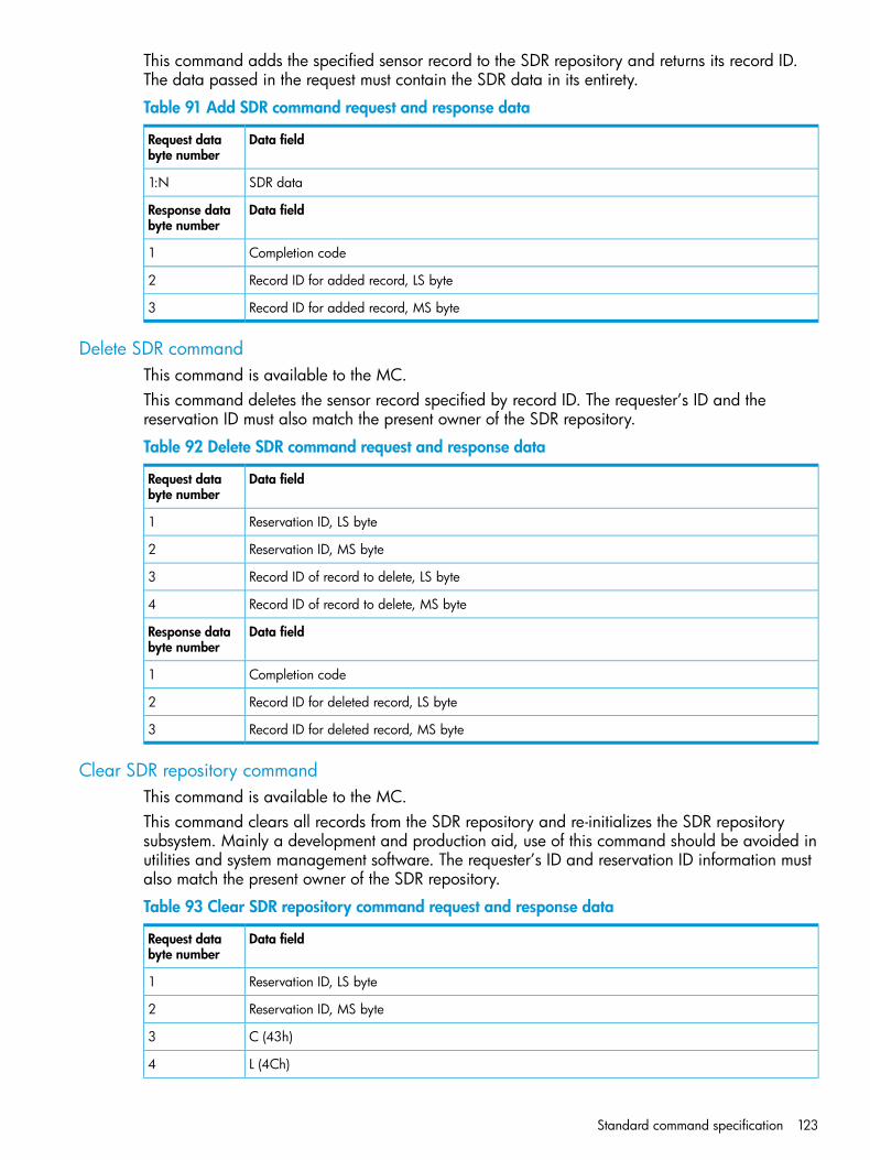
This command adds the specified sensor record to the SDR repository and returns its record ID.The data passed in the request must contain the SDR data in its entirety.
Table 91 Add SDR command request and response data
Data fieldRequest databyte number
SDR data1:N
Data fieldResponse databyte number
Completion code1
Record ID for added record, LS byte2
Record ID for added record, MS byte3
Delete SDR commandThis command is available to the MC.This command deletes the sensor record specified by record ID. The requester’s ID and thereservation ID must also match the present owner of the SDR repository.
Table 92 Delete SDR command request and response data
Data fieldRequest databyte number
Reservation ID, LS byte1
Reservation ID, MS byte2
Record ID of record to delete, LS byte3
Record ID of record to delete, MS byte4
Data fieldResponse databyte number
Completion code1
Record ID for deleted record, LS byte2
Record ID for deleted record, MS byte3
Clear SDR repository commandThis command is available to the MC.This command clears all records from the SDR repository and re-initializes the SDR repositorysubsystem. Mainly a development and production aid, use of this command should be avoided inutilities and system management software. The requester’s ID and reservation ID information mustalso match the present owner of the SDR repository.
Table 93 Clear SDR repository command request and response data
Data fieldRequest databyte number
Reservation ID, LS byte1
Reservation ID, MS byte2
C (43h)3
L (4Ch)4
Standard command specification 123

Table 93 Clear SDR repository command request and response data (continued)
R (52h)5
6 • AAH = initiate erase
• 00h = get erasure status
Data fieldResponse databyte number
Completion code1
Erasure progress2• [7:4] - reserved
• [3:0] - erasure in progress
◦ 0h = erasure in progress
◦ 1h = erase completed
Run initialization agent commandThis command is available to the MC.This command can be used to cause the initialization agent to run. The command can be used tocheck the status of the initialization agent as well.
Table 94 Run initialization agent command request and response data
Data fieldRequest databyte number
1 • [7:1] - reserved
• [0]
◦ 1b = run initialization agent
◦ 0b = get status of initialization agent process
Data fieldResponse databyte number
Completion code1
2 • [7:1] - reserved
• [0]
◦ 1b = initialization completed
◦ 0b = initialization in progress
FRU inventory device commandsThe FRU inventory data contains information such as the serial number, part number, asset tag,and a short descriptive string for the FRU. The contents of a FRU inventory record are specified inthe Platform Management FRU Information Storage Definition.The FRU inventory device is a logical device and is not necessarily implemented as a separatephysical device. The device that contains the SDR repository device also typically holds FRUinventory information for the main system board and chassis, there may also be a separate FRUinventory device that provides access to the FRU information for a replaceable module such as amemory module.
124 Command specification

Get FRU inventory area info commandThis command returns the overall size of the FRU inventory area for a device in bytes.
Table 95 Get FRU inventory area info command request and response data
Data fieldRequest databyte number
FRU device id. FFh = reserved1
Data fieldResponse databyte number
Completion code.1
FRU inventory area size in bytes, LS byte.2
FRU inventory area size in bytes, MS byte.3
[7:1] — reserved4[0] — 0b = device is accessed by bytes, 1b = device is accessed by words
Read FRU data commandThis command returns the specified data from the FRU inventory info area. This is effectively a lowlevel direct interface to a non-volatile storage area. This means that the interface does not interpretor check any semantics or formatting for the data being accessed. The offset used in this commandis a logical offset that may correspond to the physical address used in the device that provides thenon-volatile storage. For example, FRU information kept in flash at physical address 1234h, howeverthe offset 0000h would be used with this command to access the start of the FRU information. IPMIFRU device data (devices formatted per FRU) as well as process and DIMM FRU data always startsfrom offset 0000h unless otherwise noted.
NOTE: While offset values are 16–bit allowing FRU devices up to 64K words, the count toread, count returned and count written fields are 8–bits. This is in recognition of thelimitations on the size of messages. Currently IPMB messages are limited to 32–bytes total.
Table 96 Read FRU data command request and response data
Data fieldRequest databyte number
FRU device id. FFh = reserved.1
FRU inventory offset to read, LS byte.2
FRU inventory offset to read, MS byte.3Offset is in bytes or words per device access type returned in the get fru inventory areainfo command.
Count to read – count is 1 based.4
Data fieldResponse databyte number
Completion code. Generic, plus following command specific:1• 81h = FRU device busy.
The requested cannot be completed because the implementation of the logical FRU device is ina state where the FRU information is temporarily unavailable. This could be due to a conditionsuch as a loss of arbitration if the FRU is implemented as a device on a shared bus.
• Software can elect to retry the operation after at least 30 milliseconds if this code is returned.
NOTE: It is highly recommended that management controllers incorporate built-in retry mechanisms.Generic IPMI software cannot be relied upon to take advantage of this completion code
Standard command specification 125

Table 96 Read FRU data command request and response data (continued)
Count returned – count is 1 based2
Requested data.3:2+N
Write FRU data commandThis command writes the specified byte or word to the FRU inventory info area. This is a low leveldirect interface to a non-volatile storage area. This means that the interface does not interpret orcheck any semantics or formatting for the data being written. The offset used in this command isa logical offset that may correspond to the physical address used in device that provides thenon-volatile storage. For example, FRU information could be kept in flash at physical address1234h, however offset 0000h would still be used with this command to access the start of the FRUinformation. IPMI FRU device data (devices that are formatted per FRU) as well as processor andDIMM FRU data always starts from offset 0000h unless otherwise noted. Updating the FRU inventorydata is presumed to be a system level, privileged operation. There is no requirement for devicesimplementing this command to provide mechanisms for rolling back the FRU inventory area in thecase of incomplete or incorrect writes.
Table 97 Write FRU data command request and response data
Data fieldRequest data bytenumber
FRU device id. FFH = reserved1
FRU inventory offset to write, LS byte2
FRU inventory offset to write, MS byte3
Data to write4:3+N
Data fieldResponse databyte number
Completion code. Generic, plus following command specific:1• 80h = write-protected offset. Cannot complete write because one or more bytes of FRU data are
to a write-protected offset in the FRU device. An implementation may have allowed a partialwrite of the data to occur.
• 81h = FRU device busy. Refer to the preceding table Table 96 (page 125) for the description ofthis completion code.
Count written – count is 1 based2
Sensor Device Commands
Get device SDR info commandThis command returns general information about the collection of sensors in a dynamic sensordevice.
NOTE: Issuing this command without a parameter, returns LUN based device sensor information.
Regarding LUN based device sensor information, a device could implement four sensors underone LUN and twelve under another. SDR info does not return the aggregate of the sensorinformation, instead you must issue a Get Device SDR Info command for each LUN.
Table 98 Get device SDR info command request and response data
Data fieldRequest data bytenumber
Operation (optional)1
126 Command specification

Table 98 Get device SDR info command request and response data (continued)
[7:1] — reserved[0] — 1b = Get SDR count, returns the total number of SDRs in the device.0b = Get sensor count, returns the number of sensors implemented on the LUN addressed.
Data fieldResponse databyte number
Completion code1
For operation = Get sensor count (or if byte 1 not present in the request): Number of sensorsin device for the LUN this command was addressed.
2
For operation = Get SDR count, the total number of SDRs in the device.
Flags:3Dynamic population[7]0b = static sensor population. The number of sensors handled by this device is fixed and a queryshall return records for all sensors.1b = dynamic sensor population. This device may have its sensor population vary during run time(any time other than during installation).Reserved[6:4] — reservedDevice LUNs[3] — 1b = LUN 3 has sensors[2] — 1b = LUN 2 has sensors[1] — 1b = LUN 1 has sensors[0] — 1b = LUN 0 has sensors
Sensor population change indicator. LS byte first.4:7Four byte timestamp, or counter. Updated or incremented each time the sensor population changes.This field is not provided if the flags indicate a static sensor population.
Get device SDR commandThe Get Device SDR command allows SDR information for sensors and is typically implementedin a satellite management controller. It also returns SDR types in addition to 01h and 02h. This isan optional command for static sensor devices, and mandatory for dynamic sensor devices. Theformat action is similar to the get sdr command for repository devices.
NOTE: A sensor device uses consistent sensor numbers for particular sensor.
The Get Device SDR command includes a reservation id that notifies the requestor that arecord may have changed during a multi-part read.
Table 99 Get device SDR command request and response data
Data fieldRequest data bytenumber
Reservation ID. LS Byte. Only required for partial reads with a non-zero offset into record field. Use0000h for reservation id.
1
Reservation ID. MS Byte.2
Record id of record to get, LS byte. 0000h returns the first record.3
Record id of record to get, MS byte.4
Standard command specification 127

Table 99 Get device SDR command request and response data (continued)
Offset into record.5
Bytes to read. FFh means read entire record.6
Data fieldResponse databyte number
Completion code. Generic, plus command specific:180h = record changed. This status is returned if any of the record contents were altered since thelast time the requestor issued the request with 00h for the offset into SDR field.
Record id for next record, LS byte.2
Record id for next record, MS byte.3
Requested bytes from record.4:3+N
Reserve device SDR repository commandThis command is used to obtain a reservation id that is part of the mechanism used to notifythe requestor of record changes during a multi-part read.
Table 100 Reserve device SDR repository command request and response data
Data fieldResponse databyte number
Completion code1
Reservation id, LS byte 0000h reserved.2
Reservation id, MS byte3
Data fieldRequest databyte number
Sensor number (FFh = reserved)1
Get sensor thresholds commandThis command retrieves the threshold for a given sensor.
Table 101 Get sensor thresholds command response data
Data fieldResponse databyte number
Completion code1
[7:6] — reserved. Returns as 00b.2Readable thresholds: This bit mask indicates which thresholds are readable[5] — 1b = upper non-recoverable threshold[4] — 1b = upper critical threshold[3] — 1b = upper non-critical threshold[2] — 1b = lower non-recoverable threshold[1] — 1b = lower critical threshold[0] — 1b = lower non-critical threshold
lower non-critical threshold, if present, ignore on read otherwise3
lower critical threshold, if present, ignore on read otherwise4
lower non-recoverable threshold, if present, ignore on read otherwise5
128 Command specification

Table 101 Get sensor thresholds command response data (continued)
Data fieldResponse databyte number
upper non-critical threshold, if present, ignore on read otherwise6
upper critical, if present, ignore on read otherwise7
upper non-recoverable, if present, ignore on read otherwise8
Get sensor reading commandThis command returns the present reading for sensor. The sensor device may return a stored versionof a periodically updated reading, or the sensor device may scan to obtain the reading afterreceiving the request.The event/reading type code from the SDR determines the state bits returned by discrete sensors.
Table 102 Get sensor reading command request data
Data fieldRequest data bytenumber
Sensor number (FFh = reserved)1
Data fieldResponse data bytenumber
Completion code.1
Sensor reading2Byte 1: byte of reading. Ignore on read if the sensor does not return a numeric (analog) value.
[7] — 0b = All event messages disabled from this sensor.3[6] — 0b = sensor scanning disabled.[5] — 1b = reading/state unavailable (formerly: initial update in progress). This bit is set toindicate a re-arm or set event receiver command has been used to request an update ofthe sensor status, and that update has not occurred yet. Software should use this bit to avoidgetting an incorrect status while the first sensor update is in progress. This bit is only required ifit is possible for the controller to receive and process a get sensor reading or get sensorevent status command for the sensor before the update completes. This is most likely thecase for sensors, such as fan RPM sensors that may require seconds to accumulate the first readingafter a re-arm. The bit may also indicate when a reading/state is unavailable because themanagement controller cannot obtain a valid reading or state for the monitored entity, typicallybecause the entity is not present.[4:0] — reserved. Ignore on read.
For threshold-based sensors:(4)Present threshold comparison status[7:6] — reserved. Returned as 1b. Ignore on read.[5] — 1b = at or above (≥) upper non-recoverable threshold[4] — 1b = at or above (≥) upper critical threshold[3] — 1b = at or above (≥) upper non-critical threshold[2] — 1b = at or below (≤) lower non-recoverable threshold[1] — 1b = at or below (≤) lower critical threshold[0] — 1b = at or below (≤) lower non-critical thresholdFor discrete reading sensors:[7] = 1b = state 7 asserted[6] = 1b = state 6 asserted[5] = 1b = state 5 asserted[4] = 1b = state 4 asserted
Standard command specification 129

Table 102 Get sensor reading command request data (continued)
[3] = 1b = state 3 asserted[2] = 1b = state 2 asserted[1] = 1b = state 1 asserted[0] = 1b = state 0 asserted
For discrete reading sensors only. (Optional)(5)(00h Otherwise)[7] = Reserved. Returned as 1b. Ignore on read.[6] = 1b = state 14 asserted[5] = 1b = state 13 asserted[4] = 1b = state 12 asserted[3] = 1b = state 11 asserted[2] = 1b = state 10 asserted[1] = 1b = state 9 asserted[0] = 1b = state 8 asserted
DCMI specific commandsThis section includes commands specific to the Data Center Manageability Interface implementationin Moonshot. Table 103 (page 130) shows the completion codes and definitions found in data byte1 of DCMI specific command responses.
Table 103 DCMI completion codes
DefinitionCode
Command completed normally.00h
Node busy. Command could not be processed because command processing resources are temporarilyunavailable.
C0h
Invalid Command. Used to indicate an unrecognized or unsupported command.C1h
Command invalid for given LUN.C2h
Timeout while processing command. Response unavailable.C3h
Out of space. Command could not be completed because of a lack of storage space required toexecute the given command operation.
C4h
Reservation cancelled or invalid reservation ID.C5h
Request data truncated.C6h
Request data length invalid.C7h
Request data field length limit exceeded.C8h
Parameter out of range. One or more parameters in the data field of the request are out of range.This is different from ‘Invalid data field’ (CCh) code in that it indicates that the erroneous fields havea contiguous range of possible values.
C9h
Cannot return number of requested data bytes.CAh
Requested sensor, data, or record not present.CBh
Invalid data field in request.CCh
Command illegal for specified sensor or record type.CDh
Command response could not be provided.CEh
130 Command specification

Table 103 DCMI completion codes (continued)
DefinitionCode
Cannot execute duplicated request. This completion code is for devices which cannot return theresponse that was returned for the original instance of the request. Such devices should provide
CFh
separate commands that allow the completion status of the original request to be determined. Anevent receiver does not use this completion code, but returns the 00h completion code in the responseto (valid) duplicated requests.
Command response could not be provided. SDR repository in update mode.D0h
Command response could not be provided. Device in firmware update mode.D1h
Command response could not be provided. MC initialization or initialization agent in progress.D2h
Destination unavailable. Cannot deliver request to selected destination. For example, this code canbe returned if a request message is targeted to SMS, but receive message queue reception is disabledfor the particular channel.
D3h
Cannot execute command due to insufficient privilege level or other security-based restriction.D4h
Cannot execute command. Command, or request parameters, not supported in present state.D5h
Cannot execute command. Parameter is illegal because command sub-function has been disabled oris unavailable.
D6h
Unspecified error.FFh
Get DCMI capability info commandThis command provides version information for DCMI and information about the mandatory andoptional DCMI capabilities that are available on the particular platform. The command is session-less,and is a bare-metal provisioning command. The availability of features does not imply the featuresare configured. This command is supported at the Zone, Cartridge, and Node Controller.
Table 104 Get DCMI capability info command request and response data
Data fieldRequest data bytenumber
Group extension identification = DCh1
Parameter selector2
Data fieldResponse databyte number
Completion code. See Table 103 (page 130).1
Group extension identification = DCh2
DCMI specification conformance:3:4• Byte 1 — Major version (01h)
• Byte 2— Minor version (01h)
Parameter revision = 02h5
Parameter data. See Table 105 (page 132).6:N
Standard command specification 131

Table 105 DCMI Capabilities Parameters
Parameter data (non-volatile unless noted)#Parameter
This field returns the supported capabilities available in the server in conformanceto DCMI specification for both Platform and Manageability access. All reservedbits shall be set to 0b.
1Supported DCMI capabilities
• Byte 1–Reserved
• Byte 2–Platform capabilities.All bits:
◦ 0b=Not present
◦ 1b=Available
◦ [7:1] — Reserved
◦ [0] — Power management/monitoring support (Defined as support for eitherpower monitoring or power monitoring plus power limiting.)
• Byte 3–Manageability access capabilities.All bits:
◦ 0b=Not present
◦ 1b=Available
◦ [7:3] — Reserved
◦ [2] — Out-of-band secondary (second) LAN channel available (optional).
◦ [1] — Serial TMODE available (TMODE on serial port to managementcontroller) (optional)
◦ [0] — Power management/monitoring support (Defined as support for eitherpower monitoring or power monitoring plus power limiting.)
This field returns the platform attributes for the platform capabilities. All reservedbits shall be set to 0b.
2Mandatory platform attributes
• Byte 1:2–SEL attributes
[15]–SEL automatic rollover enabled (SEL overwrite) (0b=Not present,1b=available)
◦
◦ [14] Entire SEL Flush upon rollover (Valid if rollover is enabled) (0b=Notpresent, 1b=available)
◦ [13] Record level SEL flush upon rollover (Valid if rollover is enabled) (0b=Notpresent, 1b=available)
◦ [12] Reserved
◦ [11:0] Number of SEL entries (maximum of 4096) (the number of entriessupported must be 64 or great to be in conformance)
• Byte 3–4—Reserved
• Byte 5–Sample frequency for temperature monitoring (in units of 1 second)
132 Command specification

Table 105 DCMI Capabilities Parameters (continued)
Parameter data (non-volatile unless noted)#Parameter
This field returns the attributes required for the recommended platform capabilities.3Optional platform attributes• Byte 1 — Power management device slave address
[7:1] 7–bit I2C slave address on IPMB.◦◦ [0] Reserved. Write as 0b.
◦ [20h=MC, XXh=Satellite/external controller]
• Byte 2 — Power management controller channel number
◦ [7:4] Channel number for channel that management controller is located on.Use 0h for the primary MC.
◦ [3:0] Device revision (used for providing the revision control for powermanagement capability)
This field returns the attributes of the manageability access.4Manageability accessattributes • Byte 1–Mandatory primary LAN OOB support (RMCP+ support only)
[7:0] Channel number (0xFFh==Not supported)
• Byte 2–Optional secondary LAN OOB support (RMCP+ support only)[7:0] Channel number (0xFFh==Not supported)
• Byte 3–Optional serial out-of-band TMODE capability[7:0] Channel number (0xFFh==Not supported)
Get asset tag commandThis command enables management consoles or local software to get asset tag data. UTF-8encoding is identified when the first three bytes (offsets 0, 1, and 2) of the returned asset tag dataare set to the UTF-8 byte order mark (BOM) pattern, EFh, BBh, BFh, respectively. This command issupported at the Zone.
Table 106 Get asset tag command request and response data
Data fieldRequest data bytenumber
Group extension identification = DCh1
Offset to read2
Number of bytes to read (16 bytes maximum)
NOTE: If the number of bytes to read starting from the given offset to read exceeds the numberof remaining asset tag data bytes, the command will complete normally (completion code = 00h)but will only return the remaining bytes (provided the offset to read and bytes to read are withintheir correct ranges.) For example, if the asset tag length is presently 20 bytes, submitting an offsetto read of 16 and a bytes to read of 16 will be accepted, but only the asset tag data bytes atoffsets 16–19 will be returned.
3
Data fieldResponse databyte number
Completion code. C9h shall be returned if offset >62, offset to read+bytes to read >63, or bytesto read is >16.
1
The following applies to implementations that keep the DCMI asset tag and IPMI FRU asset taginformation synchronized:If the encoding indicated by the Type/Length byte in the IPMI FRU is not set to ASCII+Latin1 orthe language code for the IPMI FRU product info area is not set to English (0 or 25), the command
Standard command specification 133

Table 106 Get asset tag command request and response data (continued)
shall return the requested data bytes, but shall also return a command-specific completion codebased on the detected encoding type, as follows:• 80h=Encoding type in FRU is binary/unspecified
• 81h=Encoding type in FRU is BCD Plus
• 82h=Encoding type is FRU is 6–bit ASCII Packed
• 83h=Encoding type is set to ASCII+Latin1 but language code is not set to English (indicatingdata is 2–byte Unicode).
The management controller does not check, nor require, a BOM in the asset tag data; asset tagdata can be stored and retrieved as ASCII+Latin1 without receiving an error completion code.
Group extension identification = DCh2
Total asset tag length (must be less than or equal to 64 bytes)3
Asset tag data (starting from the offset to read)4:N
Get DCMI sensor info commandThis DCMI command returns information about a DCMI-specified sensor. A particular sensor isidentified by the combination of its entity ID and entity instance numbers. This command is supportedat the Zone, Cartridge, and System Node Controller.
Table 107 DCMI Entity ID extension
Sensor typeEntity instanceEntity IDEntity ID description
Temp (01h)0x01...n40hInlet temperature
Temp (01h)0x01...n41hCPU temperature (based onnumber of processors orcores)
Temp (01h)0x01...n42hBaseboard temperature
Table 108 Get DCMI sensor info command request and response data
Data fieldRequest data bytenumber
Group extension identification = DCh1
Sensor type2
Entity ID3
Entity instance4• 00h = Retrieve information about all instances associate with entity ID
• 01h-FFh = Retrieve only the information about particular instance
Entity instance start, used with entity instance 00h for number of instance exceeding one IPMIresponse.
5
Data fieldResponse databyte number
Completion code. See Table 103 (page 130).1
Group extension identification = DCh2
Total number of available instances for the entity ID.3
134 Command specification

Table 108 Get DCMI sensor info command request and response data (continued)
Number of record IDs in this response (maximum of 8 per response)01h for entity instance not equal to 00h.
4
SDR record ID corresponding to the entity IDs.5:6 + N• Byte 1: Record ID LS byte, used for retrieving SDR records.
• Byte 2: Record ID MS byte, used for retrieving SDR records.
NOTE: The management controller can include SDR record IDs corresponding to entities IDscompatible IPMI 2.0 specified entity IDs such as:• Request for inlet temp (40h) can also include air inlet temp info (37h)
• Request for CPU temp (41h) can also include CPU temp (03h)
• Request for baseboard temp (42h) can also include system board (07h)
Set asset tag commandThis command enables remote consoles or local software to set the asset tag data. UTF-8 encodingis identified when the first three bytes (offsets 0, 1, and 2) of the returned asset tag data are setto the UTF-8 byte order mark (BOM) pattern, EFh, BBh, BFh, respectively. Otherwise the dataencoding is assumed to be the ASCII+Latin1 subset. Note that the management controller simplystores all eight bits of each of the given asset tag data bytes. It does not check the encoding of theasset tag data bytes, nor does it check for a BOM in the data. This command is supported at theZone.Implementations that keep the asset tag in synch with the IPMI FRU data shall write the givencharacters to the asset tag field in the product info area of the IPMI FRU device and set the encodingof the corresponding type/length byte field to ASCII+Latin1.
Table 109 Set asset tag command request and response data
Data fieldRequest data bytenumber
Group extension identification = DCh1
Offset to write (0 to 62). The offset is relative to the first character of the asset tag data.2
Number of bytes to write (16 bytes maximum)
NOTE: The command must set the overall length of the asset tag (in bytes) to the value (offset towrite + bytes to write). Any pre-existing asset tag bytes at offsets past that length are automaticallydeleted.
3
Asset tag data4–N
Data fieldResponse databyte number
Completion code. C9h shall be returned if offset >62, offset+bytes to write >63, or bytes to writer>16.A C9h completion code shall also be returned if an attempt is made to writer to an offset that ismore than one great than the length of the presently stored asset tag data. Set operations for asset
1
tags must be contiguous. For example, if the asset tag is presently seven bytes long an attempt towriter starting at offset 10 will be rejected and a C9h completion code returned.
Group extension identification = DCh2
Total asset tag length. This is the length in bytes of the stored asset tag after set operation hascompleted. The asset tag length shall be set to the sum of the offset to write plus bytes to write.
3
For example, if offset to write is 32 and bytes to write is 4, the total asset tag length returned willbe 36.
Standard command specification 135
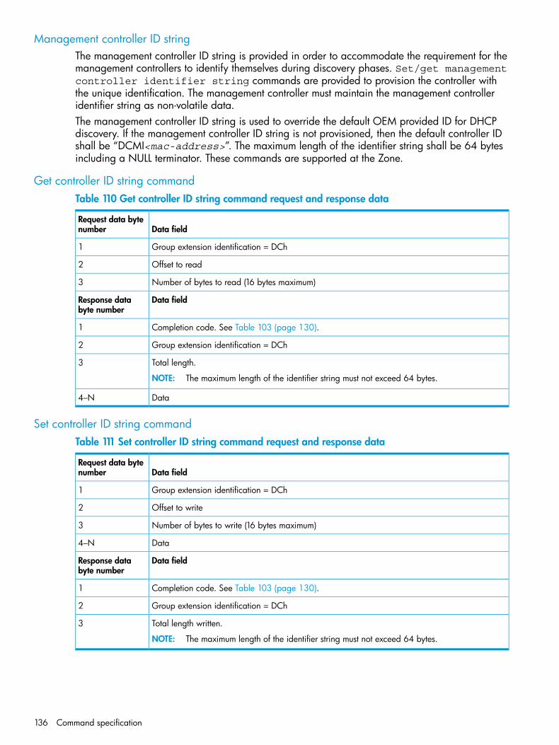
Management controller ID stringThe management controller ID string is provided in order to accommodate the requirement for themanagement controllers to identify themselves during discovery phases. Set/get managementcontroller identifier string commands are provided to provision the controller withthe unique identification. The management controller must maintain the management controlleridentifier string as non-volatile data.The management controller ID string is used to override the default OEM provided ID for DHCPdiscovery. If the management controller ID string is not provisioned, then the default controller IDshall be “DCMI<mac-address>”. The maximum length of the identifier string shall be 64 bytesincluding a NULL terminator. These commands are supported at the Zone.
Get controller ID string commandTable 110 Get controller ID string command request and response data
Data fieldRequest data bytenumber
Group extension identification = DCh1
Offset to read2
Number of bytes to read (16 bytes maximum)3
Data fieldResponse databyte number
Completion code. See Table 103 (page 130).1
Group extension identification = DCh2
Total length.
NOTE: The maximum length of the identifier string must not exceed 64 bytes.
3
Data4–N
Set controller ID string commandTable 111 Set controller ID string command request and response data
Data fieldRequest data bytenumber
Group extension identification = DCh1
Offset to write2
Number of bytes to write (16 bytes maximum)3
Data4–N
Data fieldResponse databyte number
Completion code. See Table 103 (page 130).1
Group extension identification = DCh2
Total length written.
NOTE: The maximum length of the identifier string must not exceed 64 bytes.
3
136 Command specification

PICMG specific commands
Get PICMG properties commandTable 112 Get PICMG properties command request and response data
Data fieldRequest data bytenumber
PICMG Identifier. Indicates that this is a PICMG-defined group extension command. A value of00h is used.
1
Data fieldResponse databyte number
Completion code.1
PICMG Identifier. Indicates that this is a PICMG-defined group extension command. A value of00h is used.
2
PICMG Extension Version. Indicates the version of PICMG extensions implemented by the IPMController.
3
[7:4] BCD encoded minor version[3:0] BCD encoded major versionThis specification defines version 2.3 of the PICMG extensions. IPM Controllers implementing theextensions as defined by this specification report a value of 23h. The value 00h is reserved.
Max FRU Device ID. The numerically largest FRU Device ID for the Managed FRUs implementedby this IPM Controller, excluding the following FRU Device IDs reserved at the top of the range forspecial purposes:
4
• 254 — This FRU Device ID does not represent any Managed FRU and is used only certaincommands directed at the Shelf Manager for accessing logical Shelf FRU information.
• 255 — Reserved by IPMI specification.
FRU Device ID for IPM Controller. Indicates a FRU Device ID for the FRU containing the IPMController. IPM Controllers report zero (0).
5
Get address info commandTable 113 Get address info command request and response data
Data fieldRequest data bytenumber
PICMG identifier. Indicates that this is a PICMG-defined group extension command. A value of00h is used.
1
FRU Device ID. Indicates an individual FRU site, which must identify a FRU being managed by theIPM Controller. This field is optional. If this field is not present, the command will return addressing
2
information for the FRU containing the IPM Controller that implements the command. This field isignored when Address Key Type is set to Physical Address. This field is required if Address KeyType is present.
Address Key Type. This field defines the type of address that is being provided in the Address Keyfield; only Physical Address is defined when this command is addressed to an IPM Controller. This
3
field is optional. If this field is not present, the command will return addressing information for theFRU specified by the FRU Device ID. 03h = Physical AddressAll other values reserved.
Address Key. This field is required if Address Key Type is present, and holds the Site Number ofa FRU managed by the IPM Controller in this extension.
4
Site Type. This field is required if Address Key Type is Physical Address.5
Response databyte number
Standard command specification 137
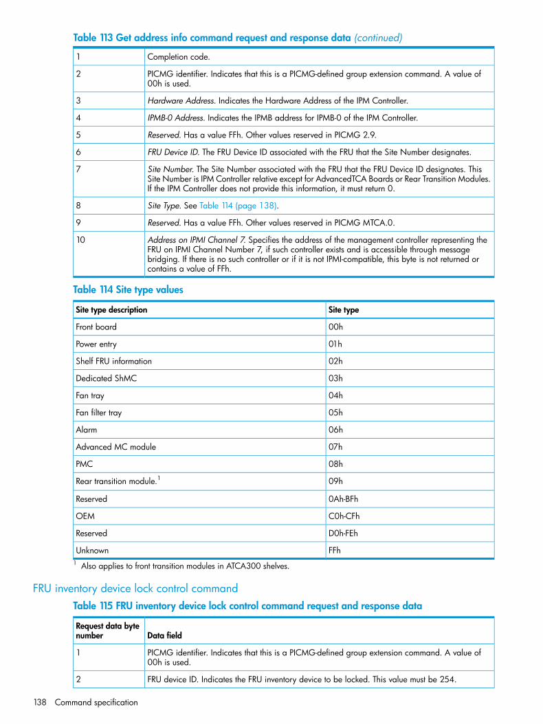
Table 113 Get address info command request and response data (continued)
Completion code.1
PICMG identifier. Indicates that this is a PICMG-defined group extension command. A value of00h is used.
2
Hardware Address. Indicates the Hardware Address of the IPM Controller.3
IPMB-0 Address. Indicates the IPMB address for IPMB-0 of the IPM Controller.4
Reserved. Has a value FFh. Other values reserved in PICMG 2.9.5
FRU Device ID. The FRU Device ID associated with the FRU that the Site Number designates.6
Site Number. The Site Number associated with the FRU that the FRU Device ID designates. ThisSite Number is IPM Controller relative except for AdvancedTCA Boards or Rear Transition Modules.If the IPM Controller does not provide this information, it must return 0.
7
Site Type. See Table 114 (page 138).8
Reserved. Has a value FFh. Other values reserved in PICMG MTCA.0.9
Address on IPMI Channel 7. Specifies the address of the management controller representing theFRU on IPMI Channel Number 7, if such controller exists and is accessible through message
10
bridging. If there is no such controller or if it is not IPMI-compatible, this byte is not returned orcontains a value of FFh.
Table 114 Site type values
Site typeSite type description
00hFront board
01hPower entry
02hShelf FRU information
03hDedicated ShMC
04hFan tray
05hFan filter tray
06hAlarm
07hAdvanced MC module
08hPMC
09hRear transition module.1
0Ah-BFhReserved
C0h-CFhOEM
D0h-FEhReserved
FFhUnknown1 Also applies to front transition modules in ATCA300 shelves.
FRU inventory device lock control commandTable 115 FRU inventory device lock control command request and response data
Data fieldRequest data bytenumber
PICMG identifier. Indicates that this is a PICMG-defined group extension command. A value of00h is used.
1
FRU device ID. Indicates the FRU inventory device to be locked. This value must be 254.2
138 Command specification

Table 115 FRU inventory device lock control command request and response data (continued)
Operation. The operation to perform on the FRU lock.30 Get last commit timestamp. Used to fetch the FRU inventory device’s last commit timestamp.1 Lock. Lock the FRU inventory device lock and return a lock 10.2 Unlock and discard. Unlock the FRU inventory device lock and discard all writes since the last
lock.3 Unlock and commit. Unlock the FRU inventory device lock and commit all writes since the last
lock.
FRU inventory device lock ID. For operations 2 and 3 above, this is the lock ID to unlock. The valuemust be zero for other operations.
4–5
Data fieldResponse databyte number
Completion code:180h Invalid FRU information. An unlock and commit operation was requested and the FRU
information was invalid.81h Lock failed. A lock operation was requested and the FRU inventory device was already
locked, or an unlock operation was requested and the FRU inventory device lock ID wasinvalid.
PICMG identifier. Indicates that this is a PICMG-defined group extension command. A value of00h is used.
2
FRU inventory device lock ID. For the lock operation, this returns the FRU inventory device lock IDfor the lock if the lock operation was successful. This value is chosen by the MC arbitrarily, but is
3–4
chosen is such a way to avoid reusing a recently used number. For all other operations this valueis set to zero.
FRU inventory device last commit timestamp. This value is the timestamp of the last successfulcommit operation on the FRU inventory device.
5–8
Standard command specification 139

6 IPMI Messaging and InterfacesIPMI uses message based interfaces for the different interfaces to the platform management subsystemsuch as IPMB, LAN, and the system interface to the MC.All IPMI messages share the same fields in the message payload regardless of the interface(transport) that they are transferred over. The same core of IPMI messages is available over everyIPMI specified interface, just wrapped differently according to the needs of the particular transport.This enables management software that works on one interface to be converted to use a differentinterface by changing the underlying driver for that particular transport. This also enables knowledgereuse, that is a developer who understands the operation of IPMI commands over one interfacecan readily apply that knowledge to a different IPMI interface.IPMI messaging uses a request/response protocol. IPMI request messages are commonly referredto as commands. The use of a request/response protocol facilitates the transfer of IPMI messagesover different transports. It also facilitates multi-master operations on busses like the IPMB, allowingmessages to be interleaved and multiple management controllers to directly intercommunicate onthe bus.IPMI commands are grouped into functional command sets, using a field called the network functioncode (NetFn). There are command sets for sensor and event related commands, chassis commands,and others. This functional grouping makes it easier to organize and manage the assignment andallocation of command values.All IPMI request messages have a network function command and optional data fields. All IPMIresponse messages carry network function command optional data and a completion code field.As inferred earlier, the differences between the different interfaces has to do with the framing andprotocols used to transfer this payload. For example, the IPMB protocol adds fields for I2C andcontroller addressing and data integrity checking and handling whereas the LAN interface addsformatting for sending IPMI messages as LAN packets.
System InterfacesIPMI defines three standard system interfaces that system software use for transferring IPMI messagesto the MC (of which Moonshot supports two). In order to support a variety of micro-controllers,IPMI offers a choice of system interface, this is also key to enabling cross-platform software. Thesystem interfaces are similar enough so that a single driver can be created that supports all IPMIsystem interfaces.The system interface connects to a system bus that can be driven by the main processor(s). Thepresent IPMI system interfaces can be I/O or memory mapped. Any system bus that allows themain processor(s) to access the specified I/O or memory locations, and meet the timingspecifications, can be used. Thus, an IPMI system interface could be hooked to the X-bus, PCI, LPCor a proprietary bus off the baseboard chipset.IPMI system interfaces:
• Keyboard controller style (KCS) — the bit definitions and operation of the registers follow thatused in the Intel 8742 Universal Peripheral Interface micro-controller. KCS reflects the fact thatthe 8742 interface was used as the legacy keyboard controller interface in PC architecturecomputer systems. This interface is available built-in to several commercially availablemicro-controllers. Data is transferred across the KCS interface using a per byte handshake.
• SMBus System Interface (SSIF) — This interface is a low pin count option that specifies accessingan MC that is connected to the system SMBus host controller. SSIF helps support lower costMC implementations by enabling an interface that can be used on low cost micro-controllersin low pin count packages.
NOTE: The SSIF typically has a much lower bandwidth to the MC than the other systeminterfaces owing to the 100 kbps maximum data rate presently specified for SM Bus.
140 IPMI Messaging and Interfaces

Message interface descriptionThe heart of this specification is the definition of the messages and data formats used forimplementing sensors, event messages, event generators and event receivers, the SDR Repository,and the SEL in the platform management architecture. These messages are designed for deliveryusing a messaging interface with a particular set of characteristics. This section presents the generalspecification of that interface, and the messages.The message interface is defined as a request/response interface. That is, a request message isused to initiate an action or set data, and a response message is returned to the requester. In thisdocument, request messages are often referred to as commands, and response messages asresponses.All messages in this specification share the same common elements as the payload to the commandinterpreter in the logical device that receives the message. The messaging interfaces differ in theframing, physical addressing, and data integrity mechanisms that are used to deliver the payload.
Table 116 Common message components
DescriptionComponent
A field that identifies the functional class of the message. The network functionclusters IPMI commands into different sets.
Network Function (NetFn)
A field that unambiguously differentiates request messages from response messages.In the IPMB protocol, this identifier is merged with the NetFn code where even
Request/Response identifier
numbered network function codes identify request messages and odd numberednetwork function codes identify response messages.
Information that identifies the source of the request. This information must be sufficientto allow the response to be returned to the correct requestor. For example, the IPMB
Requester’s ID
requesters ID consists of the slave address and LUN of the requester device. For amultiple stream system interface the requesters ID is the stream ID for the streamthrough which the request was issued.
A field that identifies the Responder to the request. In request messages this field isused to address the request to the desired responder, in response messages thisfield is used to assist the requester in matching up a response with a given request.
Responder’s ID
The messages specified in this document contain a one-bye command field.Commands are unique within a given network function. Command values can range
Command
from 00h through FDh. Code FEh is reserved for future extension of the specificationand code FFh is reserved for message interface level error reporting on potentialfuture interfaces.
The data field carries the additional parameters for a request or a response, if any.Data
IPMI Messaging InterfacesIn Moonshot, there are two system interface implementations specified for the MC: KCS and SSIF.The MC can also be reached through additional interfaces such as the IPMB and LAN interfaces.
Network function codesThe network layer in the connection header includes a six-bit field identifying the function accessed.The remaining two bits are the LUN field. The LUN field provides further sub-addressing within thenode.The network function clusters commands into functional command sets. In a parsing hierarchy, theLUN field may be thought of as the selector for a particular network function handler in the node,and the network function may be considered the selector for a particular command set handlerwithin the node.“Moonshot network function codes” (page 142) defines the supported network functions. With theexception of the application and firmware transfer network functions, the commands and responses
Network function codes 141

for a given network function are not node specific. The format and function for standard commandsets is specified later.
Table 117 Moonshot network function codes
DescriptionMeaningNameValue(s)
00h identifies the message as a command/request and 01has a response, relating to the common chassis control andstatus functions.
Chassis devicerequests andresponses
Chassis00, 01
This functionality can be present on any node. 04h identifiesthe message as a command/request and 05h as a response,
Sensor and eventrequests andresponses
Sensor/Event04, 05
relating to the configuration and transmission of eventmessages and system sensors.In Moonshot, this includes event and sensor devicecommands.
06h identifies the message as an applicationcommand/request and 07h a response. The exact format of
Application requestsand responses
Application06, 07
application messages are implementation-specific for aparticular device, with the exception of App messages thatare defined by the IPMI specifications.In moonshot, this includes IPMD global commands, MCwatchdog timer commands, and MC device and messagingcommands.
This functionality can be present on any node that providesnon-volatile storage and retrieval services.
Non-volatile storagerequests andresponses
Storage0A, 0B
In Moonshot, this includes FRU device, SDR device and SELdevice commands.
Requests (0Ch) and responses (0Dh) for IPMI-specifiedmessages that are media-specific configuration and operation,such as configuration of serial and LAN interfaces.
Media-specificconfiguration &control
Transport0C, 0D
In Moonshot, this includes LAN device and serial devicecommands.
The first data byte position in requests and responses underthis network function identifies the defining body that specifies
Non-IPMI grouprequests andresponses
Groupextension
2Ch–2Dh
command functionality. Software assumes that the commandand completion code field positions will hold command andcompletion code values.The following values are used to identify the defining body.
• 00h PICMG — PCI Industrial Computer Manufacturer’sGroup at http://www.picmg.com
• DCh DCMI specifications at http://www.intel.com/go/dcmi
• All other reserved
Moonshot supports PICMG and DCMI group extensions only.When this network function is used, the ID for the definingbody occupies the first data byte in a request, and the seconddata byte (following the completion code) in a response.
Completion codesAll response messages specified in this document include a completion code as the first byte inthe data field of the response. A management controller that gets a request to an invalid(unimplemented) LUN must return an error completion code using that LUN as the responder’s LUN(RsLUN) in the response. The completion code indicates whether the associate request messages
142 IPMI Messaging and Interfaces

completed successfully and normally, and if not, provides a value indicating the completioncondition.Completion codes work at the command level. They are responses to the interpretation of thecommand after it has been received and validated through the messaging interface. Errors at thenetwork (messaging interface) level are handled with a different error reporting mechanism.Completion code values are split into generic, device-specific (which covers OEM) andcommand-specific ranges. All commands can return generic completion codes. Commands thatcomplete successfully return the 00h command completed normally, completion code. Commandsthat produce error conditions or return a response that varied from what was specified by therequest parameters for the command, return a non-zero completion code as specified in “CompletionCodes” (page 143).
Table 118 Completion Codes
DefinitionCode
GENERIC COMPLETION CODES 00h, C0h-FFh
Command completed normally00h
Node Busy. Command could not be processed— command processing resources temporarilyunavailable.
C0h
Invalid Command. Indicates an unrecognized or unsupported command.C1h
Command invalid for given LUN.C2h
Timeout while processing command. Response unavailable.C3h
Out of Space. Command could not be completed because of a lack of storage space.C4h
Reservation canceled or invalid reservation id.C5h
Request data truncated.C6h
Invalid request data length.C7h
Request data field length limit exceeded.C8h
Parameter out of range. One or more parameters in the data field of the Request are outof range. This is different from Invalid data field (CCh) code in that it indicates that theerroneous field(s) has a contiguous range of possible values.
C9h
Cannot return number of requested data bytes.CAh
Requested sensor, data, or record not present.CBh
Invalid data field in request.CCh
Command illegal for specified sensor or record type.CDh
Command response could not be provided.CEh
Cannot execute duplicated request. This completion code is for devices which cannot returnthe response that was returned for the original instance of the request. Such devices should
CFh
provide separate commands that allow the completion status of the original request to bedetermined.
Command response could not be provided. SDR repository in update mode.D0h
Command response could not be provided. Device in firmware update mode.D1h
Command response could not be provided. MC initialization or initialization agent inprogress.
D2h
Destination unavailable. Cannot deliver request to selected destination. Example, this codecan be returned if a request message is targeted to SMS, but receive message queuereception is disabled for the particular channel.
D3h
Completion codes 143

Table 118 Completion Codes (continued)
DefinitionCode
Cannot execute command due to insufficient privilege level or other security based restriction(example, disabled for firmware firewall).
D4h
Cannot execute command. Command or request parameter(s) not supported in presentstate.
D5h
Cannot execute command. Parameter is illegal because command sub-function has beendisabled or is unavailable (example, disabled for firmware firewall).
D6h
Unspecified error.FFh
DEVICE SPECIFIC (OEM) CODES 01h — 7Eh
Device specific (OEM) completion codes. This range is used for command specific codesthat are also specific for a particular device and version. A priori knowledge of the devicecommand set is required for interpretation of these codes.
01h — 7Eh
COMMAND SPECIFIC CODES 80h — BEh
Standard command specific codes. This range is reserved for command specific completioncodes for commands specified in this document.
80h — BEh
Reserved.all other
Additional command specific completion codes, if any, are listed in the completion code fielddescription for the command. In some cases, use of certain command specific completion codesis mandatory. This will be listed alongside the description of the completion code in the commandtable. If no command specific completion codes are listed, the description will solely indicate thatthe field is the completion code field.
NOTE: The generic completion code values can be used with any command, regardless ofwhether additional command specific completion codes are defined.
Channel Model, Authentication, Sessions, and UsersIPMI v2.0 incorporates a common communication infrastructure referred to as the Channel Model.Channels provide the mechanism for directing the routing of IPMI messages between differentmedia connections to the MC. A channel number identifies a particular connection. For example,0 is the channel number for the primary IPMB. Up to nine total channels can be supported (theSystem Interface and primary IPMB, plus seven additional channels with a media type assignedby the implementer.) Channels can thus be used to support multiple IPMB, LAN, Serial, etc.,connections to the MC.Channels can be session-based or session-less. A session is used for two purposes:1. As a framework for user authentication.2. To support multiple IPMI messaging streams on a single channel.Session-based channels thus have at least one user login and support user and messageauthentication. Session-less channels do not have users or authentication. A LAN channel issession-based, while the System Interface and IPMB are examples of session-less channels.In order to do IPMI messaging using a session, a session must first be activated. Activating a sessionauthenticates a particular user.A session has a Session ID that is used for tracking the state of a session. The Session IDmechanism allows multiple sessions to be simultaneously supported on a channel.The concept of user is essentially a way to identify a collection of privilege and authenticationinformation. User configuration is done on a per channel basis. This means that a given user couldhave a different password and set of privileges for accessing the MC via a LAN channel than viaa serial channel.
144 IPMI Messaging and Interfaces

Privilege Levels determine which IPMI commands a given user can execute over a given channel.Privilege Limits set the maximum privilege level at which a user can operate. A user is configuredwith a given maximum privilege limit for each channel. In addition, there is a Channel PrivilegeLimit that sets the maximum limit for all users on a given channel. The Channel PrivilegeLimit takes precedence over the privilege configured for the user. Thus, a user can operate at aprivilege level that is no higher than the lower of the User Privilege Limit and the ChannelPrivilege Limit.
Channel numbersEach interface has a channel number that is used when configuring the channel and for routingmessages between channels. Only the channel number assignments for the primary IPMB and theSystem Interface are fixed, the assignment of other channel numbers can vary on a per-platformbasis. Software uses a Get Channel Info command to determine what types of channels areavailable and what channel number assignments are used on a given platform. The following tabledescribes the assignment and use of the channel numbers:
Table 119 Moonshot channel number assignments
DescriptionType/ProtocolChannelNumber
Assigned for communication with the primary IPMB. IPMB protocols areused for IPMI messages.
Primary IPMB0h
Assigned for communication between the zone MC and the LAN. RMCP+is used as the protocol.
LAN2h
Secondary IPMB, used for communication between the cartridge and systemnode controllers. IPMB protocols are used.
IPMB_L7h
The value Eh is used as a way to identify the current channel that thecommand is being received from, for example, if software wants to know
Present channelEh
what channel number it’s presently communicating over, it can find out byissuing a Get Channel Info command for channel E.
Assigned for routing messages to the system interface.System interfaceFh
Logical channelsFrom the IPMI Messaging point-of-view, a party that bridges a message from one channel to anotheronly is mainly concerned that it gets the correct response from the MC. Often, it does not matterto remote console or system software whether the target channel and devices are physicallyimplemented or not. For example, in Moonshot the IPMB and IPMB-L are logical channels.
Channel Privilege LevelsChannel privilege limits determine the maximum privilege that a user can have on a given channel.One channel can be configured to allow users to have up to Administrator level privilege, whileanother channel may be restricted to allow no higher than User level. The privilege level limits takeprecedence over the privilege level capabilities assigned per user.Channels can be configured to operate with a particular maximum Privilege Level. Privilege levelstell the MC which commands are allowed to be executed via the channel. The Set ChannelAccess command sets the maximum privilege level limit for a channel. The Set SessionPrivilege Level command requests the ability to perform operations at a particular privilegelevel. The Set Session Privilege Level command can only be used to set privilege levelsthat are less than or equal to the privilege level limit for the entire channel, regardless of the privilegelevel of the user.
Channel Model, Authentication, Sessions, and Users 145

Table 120 Channel privilege levels
DescriptionChannel privilege level
Lowest privilege level. Only commands necessary to support initiating a Callback areallowed.
Callback
Primarily commands that read data structures and retrieve status. Commands that can beused to alter MC configuration, write data to the management controllers, or performsystem actions such as resets, power on/off, and watchdog activation are disallowed.
User
All MC commands are allowed, except for configuration commands that can change thebehavior of the out-of-band interfaces. For example, operator privilege does not allow thecapability to disable individual channels or higher.
Operator
All MC commands are allowed, including configuration commands. An administrator caneven execute configuration commands that would disable the channel that the administratoris communicating over.
Administrator
Users & Password supportUser in this specification refers to a collection of data that identifies a password for establishingan authenticated session and the privileges associated with that password. For configurationpurposes, sets of user information are organized and accessed according to a numeric User ID.When activating a session, user information is looked up with a text username.
NOTE: In Moonshot and HP iLO, anonymous users are not supported due to security concerns.
User access can be enabled on a per channel basis. Thus, different channels can have differentsets of users enabled.If desired, a username on one channel can be associated with a different password than the sameusername on a different channel. When a session is activated the MC scans usernames sequentiallystarting with User ID 1 and looks for the first user with matching username and access granted forthe given channel. Thus, having different passwords for a given username requires configuringmultiple user entities — one for each different password being used for a particular set of channels.The specification allows a number of different implementations for supporting users on a channel.Minimum requirements include:
• No anonymous user access.
• User names may be fixed or configured, or a combination of both, at the choice of theimplementation.
• Support for configuring user passwords for all User IDs is required.
• Support for setting per user privilege limits is optional. If the Set User Access commandis not supported, the privilege limits for the channel are used for all users.
IPMI sessionsAuthenticated IPMI communication to the MC is accomplished by establishing a session. Onceestablished, a session is identified by a Session ID. The Session ID may be thought of as a handlethat identifies a connection between a given remote user and the MC, using either the LAN orSerial/Modem connection.The specification supports having multiple active sessions established with the MC. Moonshotsupports up to 58 simultaneous sessions at the zone.The specification also allows a given endpoint (identified by an IP address) on the LAN to openmore than one session to a MC. This capability allows a single system to serve as a proxy providingMC LAN sessions for other systems. It is not intended for one system to use this provision to openmultiple session to the MC for that systems sole use.
146 IPMI Messaging and Interfaces

An IPMI messaging connection to the MC fits one of three classifications, session-less, single-session,or multi-session.
Session-less connectionsA session-less connection is unauthenticated. There is no user login required for performing IPMImessaging. The System Interface and IPMB are examples of session-less connections.A special case of a session-less connection can occur over an interface that supports session-basedmessaging. Session-based connections have certain commands that are accepted and respondedto outside of a session. When that occurs, the channel is effectively operating in a session-lessmanner for those commands. Commands that are handled outside of a session have fixed valuesfor session-specific fields in the message. For example, when the Get ChannelAuthentication Capabilities is sent over a LAN channel outside of a session, the SessionID is set to NULL and authentication type set to NONE in the IPMI session header. Note thatcommands accepted outside of a session can also be accepted within the context of a session, inwhich case they must have valid Session IDs, etc. in the session header to be accepted.
Session inactivity timeoutsA session is automatically closed if no new, valid message has been received for the session withinthe specified interval since the last message. The session must be re-authenticated to be restored.A remote console can optionally use the Activate Session command to keep a session openduring periods of inactivity.Note that only an active session will keep the Session Inactivity Timeout from expiring.IPMI message activity that occurs outside of an active session has no effect. This is to preventsomeone from keeping a phone connection indefinitely while trying to guess different passwordsto activate a session.The MC only monitors for inactivity while the connection is switched over to the MC. Note thatclosing a session is not always the same as hanging up a modem connection. Serial/modemsessions are also automatically closed when the connection is switched over to the system, but thephone connection remains active. The MC only terminates the phone connection if a session isclosed due to an inactivity timeout while the serial connection is routed to the MC.The timeout and tolerance values are specified for the MC that will timeout and close the session.System software should take this tolerance into account, plus any additional delays due to mediatransmission times, etc.An implementation can provide an option to allow timeout configuration via a parameter in theconfiguration parameters for the given channel type.
System interface messagingMessaging between system software and the other management BUSes such as the IPMB, isaccomplished using channels and a Receive Message Queue. A channel is a path throughthe MC that allows messages to be sent between the system interface and a given bus or messagetransport. The Receive Message Queue is used to hold message data for system software untilsystem software can collect it. All channels share the Receive Message Queue for transferringmessages to system management software. The Receive Message Queue data contains channel,session, and IPMI addressing information that allows system software to identify the source of themessage, and to format a message back to the source if necessary.System management software is responsible for emptying the Receive Message Queue wheneverit has data in it. Messages are rejected if the Receive Message Queue gets full. It is recommendedthat the Receive Message Queue have at least two slots for each channel. The ReceiveMessage Queue is a logical concept. An implementation may choose to implement it as an actualqueue, or could implement separate internal buffers for each channel. It is recommended that theimplementation attempt to leave a slot open for each channel that does not presently have a
System interface messaging 147

message in the queue. This helps prevent lockout by having the queue fill with just messages fromone interface.The MC itself can, if necessary, use the Receive Message Queue and Messaging Channelsto send asynchronous messages to system management software. The recommended mechanismfor accomplishing this is to define a unique channel with a protocol type of system. To send anasynchronous message to system software the MC would place a message from that channeldirectly into the Receive Message Queue in System format. System software would be able torespond back to the MC using a Send Message command for that channel.
BridgingMC Messaging Bridging provides a mechanism for routing IPMI Messages between different media.Bridging is only specified for delivering messages between channels; it is not specified for deliveringmessages between two sessions on the same channel.With IPMI 2.0, bridging is extended to support delivering IPMI messages between activeconnections/sessions on the same channel.There are three mechanisms for bridging messages between different media connected to the MC,depending on the message target:
• MC LUN 10b — used for delivering messages to the System Interface. The MC automaticallyroutes any messages it receives via LUN 10b to the Receive Message Queue.
• Send Message command from System Interface — used for delivering messages to otherchannels, such as the IPMB. The messages appear on the channel as if they’ve come fromMC LUN 10b. Thus, if the message is a request message, the response goes to MC LUN 10band the MC automatically places the response into the Receive Message Queue for retrieval.System software is responsible for matching the response up with the original request, thusthe No Tracking setting in the Send Message command.
• Send Message command with response tracking — used with response tracking for bridgingrequest messages to all other channels except when the System Interface is the source ordestination of the message.
MC LUN 10bMessages to SMS are always routed to the Receive Message Queue and the Send Messagecommand is not typically used. Messages to SMS are delivered via the MC SMS LUN 10b. TheMC automatically reformats and places any messages that are addressed to LUN 10b into theReceive Message Queue for SMS to retrieve using the Get Message command.Sending a request to SMS requires formatting the command so that it is address to MC LUN 10b.SMS can retrieve the request from the Receive Message Queue, extract the originator’s addressand channel info, and then use the Send Message command to deliver a response.The MC does not track requests and responses for messages to system software because the ReceiveMessage Queue provides the channel and session information necessary to format the SendMessage command to deliver the response. System software is capable of tracking the channeland session information it used when generating a request. The No Tracking option is used forSend Message commands from system software.The responder then delivers its response message to MC LUN 10b and the response gets routedto the Receive Message Queue. Conversely, if a channel wants to deliver a message to SMS, itsends the request message to MC LUN 10b, and later SMS uses a Send Message command toreturn the response from MC LUN 10b.
148 IPMI Messaging and Interfaces

Send Message command with response trackingThe Send Message command is used primarily to direct the MC to act as a proxy that translatesa message from one IPMI messaging protocol to another. The MC formats the data for the targetchannel type and protocol and delivers it to the selected medium.Media such as the IPMB do not include channel number and session information as part of theiraddressing information. As a result, request messages from another channel must be delivered asif they originated from the MC itself.If the bridged message is a request, it is necessary for the MC to hold onto certain data, such asoriginating channel and session information, so that when the response message comes back itcan reformat the response and forward it back to the originator of the request. The primary waythe MC accomplishes this is by assigning a unique sequence number to each request that itgenerates, and saving a set of information in a Pending Bridged Response table that is later usedto reformat and route a response back to the originator of the request.The sequence number returned in the response is used to look up who generated the originalresponse, the saved formatting and address information. The MC then reformats and delivers theresponse to the original requester and deletes the request from its list of pending responses. TheSend Message command includes a parameter that directs the MC to save translation informationfor and track outstanding request messages for the purpose of routing the response back to theoriginator of the Send Message command.
NOTE: With the exception of messages to SMS, when the Send Message command is usedto deliver a message to a given medium the message appears to have been originated by the MC.This means that a controller on the IPMB can’t generically distinguish a bridged request from SMSfrom a bridged request from LAN.
Table 121 Message bridging mechanism by source and destination
MC tracks pendingresponses
DeliveryMechanismMessage Type and direction
noSend MessageRequest or Response from system interface to any other channel
noMC LUN 10bRequest or Response to system interface from any other channel
yesSend MessageRequest from any channel except system interface to IPMB
yesMC LUN 00bResponse from IPMB to any channel except system interface
Bridged Request ExampleThis example illustrates a Send Message command from the LAN being used to deliver a requestto IPMB.The MC uses the sequence number that it places on the bridged request to identify the channelwhere the request came from and where to send the response. It is important for the MC to ensurethat unique sequence numbers are used for pending requests from each channel. It is also importantthat sequence numbers are unique for successive requests to a given responder. One way tomanage sequence numbers to the IPMB is to track them on a per responder basis. This can be keptin a table of Pending Bridged Response information.In order to get the response back to the LAN, the IPMB response must return the same sequencenumber that was passed in the request. The management controller uses the sequence number tolook up the channel type specific addressing, sequence number, and security information that itstored when the request was forwarded. For example, if the channel type is LAN then the responsemessage must be formatted up in an RMCP/UDP packet with the IP address of the requester, thesequence number passed in the original request, the appropriate security key information, and soon.
Bridging 149

When a request message is bridged to another channel by encapsulating it in a Send Messagecommand (from a source channel other than the system interface), the MC immediately returns aresponse to the Send Message command itself. Meanwhile, the request is extracted from theSend Message command and forwarded to the specified target channel.The Send Message command must be configured to direct the MC to keep track of data in therequest so when the response comes back from the target device it can be forwarded by the MCback to the channel that delivered the original Send Message command to the MC. When theresponse comes back from the target, the MC uses the tracking information to form at the responsefor the given channel. To the party that initiated the Send Message command, the response willappear as if the encapsulated request was directly executed by the MC.For example, suppose a Get Device ID command has been encapsulated in a Send Messagecommand directed to the IPMB from a LAN channel. The MC will immediately send a response tothe Send Message command back on the LAN. The MC will extract the encapsulated GetDevice ID message content and format it as a Get Device ID request for IPMB. The targetdevice on IPMB responds with a Get Device ID response message in IPMB format. The MC takesthe tracking information that was stored when the Send Message command was issued, anduses it to create a Get Device ID response in LAN format. The Responder’s address information inthat response can either be that of the MC, of the device on IPMB that the request was targetedat the choice of the MC implementation. Parties that initiate this type of bridged request using theSend Message command should accept responses from the MC that use either address.The following figure and steps present an example high-level design for handling a bridged request.Note that the example shows information that is generated and stored, but it does not show anyparticular code module that would perform that operation. That is, the choice of which functionsare centralized, which are in a LAN module, and which are in an IPMB module is left to theimplementer.
Figure 3 LAN to IPMB bridged request example
150 IPMI Messaging and Interfaces

1. When the MC receives the Send Message command with the Bridged Request parameterbit set, it checks for an available entry in a Pending Bridged Response table and copiesparameters from the request to be bridged. When the response comes back, these parameterswill be used to validate that the response matches the earlier request and to reformat theresponse for the originating channel. The bold outlined boxes represent parameters and datain the Send Message command that will ultimately be copied to the resulting request on thetarget channel.
2. Any channel session information necessary to get the response back to the original requesterwill also need to be recorded. In this example, the MC maintains a separate table of sessioninformation for the LAN channel. An offset into that table is used as a handle for identifyingthe session information associated with the request. This handle is used in the Pending BridgedResponse table in place of copying all the session information. Note that with such animplementation, it is important to remember details such as invalidating and freeing any bridgetable entry associated with that session if the session should get closed while responses arepending.
3. In this example, the MC has a separate Sequence Number Allocator routine that ensures thatsequence numbers used in bridged requests are kept unique for a given channel. This is doneso that the response comes back, the sequence number can be used to look up correspondingrequest info entries from the Pending Bridged Response table.
4. Responses have a five second Sequence Number Expiration interval. If a response is notreceived by the expiration interval, the corresponding entry in the Pending Bridged Responseentry is deleted and the sequence number associated with the request can be reused. TheSequence Number Expiration column in this example represents a possible implementationwhere the value is decremented nominally once every 10 minutes. The entry is considered tobe free when the number reaches 0. In this example the Sequence Number Expiration fieldcould be used both for tracking sequence number expiration as well as a mechanism formarking availability of the table entry.
5. The MC takes the indicated values and uses them to construct the bridged request. The requestis a combination of field values copied from the original Send Message command and valuesgenerated by the MC. The MC generated values are shown with a bold, underlined typefacewith an asterisk.
IPMB access via master write-read commandWhen an IPMB is implemented in the system, the MC serves as a controller to give system softwareaccess to the IPMB. The IPMB allows non-intelligent devices as well as management controllers onthe bus. To support this operation, the MC provides the Master Write-Read command via its interfacewith system software. The Master Write-Read command provides low-level access to non-intelligentdevices on the IPMB, such as FRU SEEPROMs.The Master Write-Read command provides a subset of the possible I2C and SM BUS operationsthat covers most I2C/SM BUS-compatible devices.In addition to supporting non-intelligent devices on the IPMB, the Master Write-Read commandalso provides access to non-intelligent devices on Private Busses behind management controllers.The main purpose of this is to support FRU SEEPROMs on Private Busses.
MC IPMB LUNsA MC supports several LUNs to which messages are sent via the IPMB interface. These LUNs areused to identify different sub-addresses within the MC.In Moonshot, since the system interface is only implemented at the system node controller, the SMSmessage LUN is only applicable to the system interface node controllers.
Bridging 151

Table 122 MC IPMB LUNs
Long DescriptionShort DescriptionLUN
Event Request Messages received on this LUN are routed to the EventReceiver Function in the MC and automatically logged if SEL logging isenabled.
MC commands and EventRequest Messages
00b
OEM — reserved for MC implementer/system integrator definition.OEM LUN 101b
Messages received on this LUN are routed to the Receiver MessageQueue and retrieved using a Read Message command. The SMS_Availflag is set whenever the Receive Message Queue has valid contents.
SMS Message LUN (intendedfor messages to SystemManagement Software)
10b
OEM — reserved for MC implementer/system integrator definitionOEM LUN 211b
Sending Messages to IPMB from system software
NOTE: In Moonshot, since the system interface is only implemented at the system node controller,the SMS message LUN is only applicable to the system interface node controllers.
SMS can use the MC for sending and receiving IPMB messages. Both IPMB request and responsemessages can be sent and received using this mechanism. Therefore, not only can system softwaresend requests to the IPMB and receive responses from the IPMB, it is also possible for systemsoftware to receive requests from the IPMB to send back IPMB responses.System software sends messages to the IPMB through the system interface using the MC as anIPMB controller. This is accomplished by using the Send Message command to write the messageto the IPMB (channel 0). The MC does not place any restrictions on the type or content of the IPMBmessage being sent. System management software can send any IPMB request or response messageit desires provided that the message meets the maximum length requirements of the Send Messagecommand.System Management Software is responsible for providing all fields for the IPMB message, includingRequester and Responder Slave addresses and checksums. The following figures show an exampleusing the Send Message command to send a Set Event Receiver command to an IPMB deviceat slave address 52h, LUN 00b, via the system interface. The example command sets the EventReceiver address to 20h — MC.The heavy bordered fields show the bytes for the IPMB message carried in the Send Messagecommand. The requesters LUN field (rqLUN) is set to 10b (MC SMS LUN). This directs the responderto send the response to the Set Event Receiver command to the system node’s ReceiveMessage Queue.
Figure 4 IPMB request sent using Send Message command
Figure 5 Send Message command response
152 IPMI Messaging and Interfaces

The response is for the Send Message command and not for the Set Event Receivercommand. The response to the Set Event Receiver command is returned later in the ReceiveMessage Queue. System software uses the Get Message command to read messages from theReceive Message Queue. System software keeps track of any outstanding responses and matchesresponses up with corresponding requests as they are returned. System software must also keeptrack of the protocol assigned to the particular channel in order to interpret the response to theGet Message command.
Keyboard Controller Style InterfaceThe Keyboard Controller Style (KCS) is one of the supported MC to SMS interfaces. The KCSinterface is specified solely for SMS messages.The KCS Interface supports polled operations. Implementations optionally provide an interruptdriven by the OBF flag, this must not prevent driver software from using the interface in a polledmanner. This allows software to default to polled operation. It also allows software to use the KCSinterface in a polled mode until it determines the type of interrupt support. Methods for assigningand enabling such an interrupt are outside the scope of this specification.
KCS Interface/MC LUNsLUN 00b is typically used for all messages to the MC through the KCS Interface. LUN 10b isreserved for Receive Message Queue use and should not be used for sending commands to theMC. Note that messages encapsulated in a Send Message command can use any LUN in theencapsulated portion.
KCS Interface-MC Request message formatRequest Messages are sent to the MC from system software using a write transfer through the KCSinterface. The message bytes are organized according to the following format specification:
Figure 6 KCS Interface/MC Request Message format
Where:
This is a sub-address that allows messages to be routed to different LUNS that reside behind the samephysical interface. The LUN field occupies the least significant two bits of the first message byte.
LUN
Provides the first level of functional routing for messages received by the MC via the KCS Interface. TheNetFn field occupies the most significant six bits of the first message byte. Even NetFn values are usedfor requests to the MC, and odd NetFn values are returned in responses from the MC.
NetFN
This message byte specifies the operation that is to be executed under the specified Network Function.Cmd
Zero or more bytes of data, as required by the given command. The general convention is to pass dataLS-byte first, but check the individual command specifications to be sure.
Data
MC-KCS Interface Response Message formatResponse Messages are Read Transfers from the MC to system software via the KCS interface. TheMC only returns responses via the KCS Interface when data needs to be returned. The messagebytes are organized according to the following format specification:
Keyboard Controller Style Interface 153

Where:
Returns the LUN that was passed in the Request Message.LUN
A return of the NetFn code that was passed in the Request Message. Except that an odd NetFn valueis returned.
NetFn
Return of the Cmd code that was passed in the Request Message.Cmd
Indicates whether the request completed successfully.CompletionCode
Zero or more bytes of data. The MC always returns a response to acknowledge the request, regardlessof whether data is returned.
Data
LAN InterfaceThe LAN interface specifications define how IPMI messages can be sent to and from the MCencapsulated in Remote Management Control Protocol (RMCP) packet datagrams. This capabilityis also referred to as IPMI over LAN. IPMI also defines the associated LAN specific configurationinterfaces for settings things such as IP address other options, as well as commands for discoveringIPMI based systems.The Distributed Management Task Force (DMTF) specifies the RMCP format. This same packetformat is used for non-IPMI messaging via the DMTF’s Alert Standard Forum (ASF) specification.Using the RMCP packet format enables more commonality between management applications thatoperate in an environment that includes both IPMI based and ASF based systems.IPMI v2.0 defines and extended packet format and capabilities that are collectively referred to asRMCP+ and defined under the IPMI specific portion of an RMCP packet. RMCP+ utilizesauthentication algorithms that are more closely aligned with the mechanisms used for the ASF 2.0specification. In addition, RMCP+ adds data confidentiality (encryption) and payload capability.In Moonshot, IPMI v2.0/RMCP+ is implemented for the LAN interface.
Remote Management Control Protocol (RMCP)The Distributed Management Task Force (DMTF) has defined a RMCP for supporting pre-OS andOS absent management. RCMP is a simple request-response protocol that can be delivered usingUDP datagrams. IPMI-over-LAN uses version 1 of the RMCP protocol and packet format.RMCP includes a field that indicates the class of messages that can be embedded in an RMCPmessage packet, including a class for IPMI messages. Other message classes are ASF and OEM.An IPMI LAN implementation can also use ASF-class Ping and Pong messages to support thediscovery of IPMI managed systems on the network.
RMCP port numbersRMCP uses two well-known ports under UDP. “RMCP Port Numbers” (page 154) describes theseports and summarizes their use.
Table 123 RMCP Port Numbers
DescriptionNamePort#
The Primary RMCP Port — This port and the required RMCP messages must beprovided to conform with RMCP specifications.
Aux bus Shunt(Primary RMCP Port)
623 (26Fh)
There is a mandatory set of messages required to be supported on this port.These messages are always sent in the clear so that system software can discoversystems that have RMCP support.
Referred to as the secondary RMCP port or secure port, it is only used when itis necessary to encrypt packets using an algorithm or specification that prevents
Secure Aux BUS(Secondary RMCPPort)
664 (298h)
also sending unencrypted packets from being transferred via the same port.
154 IPMI Messaging and Interfaces

Table 123 RMCP Port Numbers (continued)
DescriptionNamePort#
Since discovery requires sending in the clear RMCP ping/pong packets, thesecondary port is used to transfer encrypted transfers while the primary portcontinues to support unencrypted packets.An implementation that utilizes this port must still support the Primary RMCP portand the required messages on that port in order to be conformant with the RMCPspecifications.Note that the common IPMI messaging protocols and authentication mechanismsin this specification do not use encrypted packets at the RMCP level (encryptedpackets in IPMI are defined under the IPMI message class), therefore IPMImessaging does not need to use the secondary port.
RMCP Message FormatThere are two types of RMCP messages: Data or Normal RMCP messages and RMCP acknowledgemessages. Data messages and ACK messages are differentiated by the ACK/normal bit of theclass of message field.
Table 124 RMCP Message Format
DescriptionSize in bytesField
RMCP Header
06h = RMCP Version 1.01Version
00h1Reserved
Varies, see text1Sequence Number
This field identifies the form of the messages that follow this header. Allmessages of class ASF (6) conform to the formats defined in this specificationand can be extended via an OEM IANA.
1Class of Message
Bit 7 RMCP ACK0 — Normal RMCP message1 — RMCP ACK messageBit 6:5 ReservedBit 4:0 Message Class0–5 = Reserved6 = ASF7 = IPMI8 = OEM definedall other = Reserved
RMCP Data
data based class of messageVariableData
The following table presents how the ACK/Normal Bit and the message class combine to identifythe type of message under RMCP and which specification defines the format of the associatedmessage data.
Table 125 Message Type Determination Under RMCP
Message DataMessage TypeMessage ClassACK/Normal bit
No Data. Message contains only RMCP heading, andsequence number from the last message received.
RMCP ACKASFACK
not allowedundefinedall otherACK
LAN Interface 155

Table 125 Message Type Determination Under RMCP (continued)
Message DataMessage TypeMessage ClassACK/Normal bit
Per ASF specificationASF MessagesASFnormal
bytes:3 = OEM IANAOEM messageunder RMCP
OEMnormal
bytes 4:N = OEM message data (defined by manufacturer ororganization identified by the OEM IANA field value)
Per this specificationIPMI messagesIPMInormal
Serial Over LAN (SOL)SOL is the name for the redirection of baseboard serial controller traffic over an IPMI session. Thisenables asynchronous serial-based OS and pre-OS communication over a connection to the MC.SOL can be used to provide a user at a remote console a means of interacting with serial text-basedapplications over the IPMI LAN session. A single remote console application can use SOL tosimultaneously provide LAN access to IPMI platform management and serial text redirection undera unified user interface. SOL is implemented as a payload type under the IPMI v2.0 RMCP+protocol. Access privileges for SOL are managed under the same user configuration interfaces thatare used for IPMI management. This simplifies the creation of configuration software, remotemanagement applications, and cross-platform configuration utilities.
156 IPMI Messaging and Interfaces

7 Support and other resourcesInformation to collect before contacting HP
Be sure to have the following information available before you contact HP:
• Software product name
• Hardware product model number
• Operating system type and version
• Applicable error message
• Third-party hardware or software
• Technical support registration number (if applicable)
How to contact HPUse the following methods to contact HP technical support:
• In the United States, see the Customer Service / Contact HP United States website for contactoptions:http://www.hp.com/go/assistance
• In the United States, call +1 800 334 5144 to contact HP by telephone. This service is available24 hours a day, 7 days a week. For continuous quality improvement, conversations might berecorded or monitored.
• In other locations, see the Contact HP Worldwide website for contact options:http://www.hp.com/go/assistance
HP authorized resellersFor the name of the nearest HP authorized reseller, see the following sources:
• In the United States, see the HP U.S. service locator web site:http://www.hp.com/service_locator
• In other locations, see the Contact HP worldwide web site:http://welcome.hp.com/country/us/en/wwcontact.html
Related information
Documents• HP Moonshot Documentation Overview
• HP Moonshot Configuration and Compatibility Guide
• HP Moonshot 1500 Chassis Setup and Installation Guide
• HP Moonshot 1500 Chassis Maintenance and Service Guide
• Important Download Documentation, Drivers, and Software and Firmware Updates
• HP Moonshot Troubleshooting Guide
• Safety, Compliance, and Warranty Information
• HP Moonshot iLO Chassis Management Firmware User Guide
• HP Moonshot Component Pack Release Notes
Information to collect before contacting HP 157

These documents are on the HP website at:http://www.hp.com/go/moonshot/docs
Websites• HP Moonshot website:
http://www.hp.com/go/moonshot
• HP Moonshot Component Pack download website:http://www.hp.com/go/servers/moonshot/download
• Intel IPMI specification website:http://www.intel.com/design/servers/ipmi/tools.htm
158 Support and other resources

A Command AssignmentsThe following lists the commands defined in this specification and the minimum privilege levelrequired to execute a given command. In addition, the following apply:• Unless otherwise specified, unauthenticated, session-less interfaces, such as the System Interface
and IPMB, can support any IPMI command.• The privilege level requirements for OEM commands (NetFn=OEM, OEM/Group) is specified
by the OEM identified by the corresponding manufacturer ID.• Note that the Send Message and Master Write-Read commands are not available at
the User privilege level, with the exception of using a Send Message command to delivera message to the System Interface. This is because these commands enable unfiltered accessthe IPMB, ICMB, private management busses, and PCI Management Bus. This would potentiallyallow someone to use those commands to send commands to other controllers or write tonon-intelligent devices on those busses. As a consequence, a User is only able to read FRUand sensors directly managed by the MC. In addition, FRU must be accessed via the ReadFRU command and not Master Write-Read.
• The Send Message command can be used to deliver a message to the System Interface atUser privilege level. It is up to the system software to determine the privilege level and placeany additional restrictions on messages received via the Receive Message Queue. This canbe accomplished by using the session handle associated with the message and the GetSession Info command to look up the privilege level that the user is operating at. Softwarecan also check the limits for the channel and the user by using information from the GetChannel Access and Get User Access commands to determine whether a given userhas sufficient privilege to deliver a particular command to system software.
Unless otherwise specified, the listed IPMI commands, if supported, must be accessible via LUN00b.
Key for Table 126 (page 160)• b = Command only generated by MC, can be sent prior to a session being established• b1 = Command only generated by MC, can only be delivered to a session-less channel, or
a channel that has an active session• b2 = Command only generated by MC, can be sent to a serial channel when serial port
sharing is used and activating the SOL payload causes the serial session to be terminated.• b3 = Command only generated by MC, can only be delivered to a session-less channel.• p = Works at any privilege level, can be sent prior to a session being established• s = Command executable via system interface only• X = Supported at given privilege level or higher• I = Command executable from local interfaces only (e.g. IPMB, SMBus, PCI Mgmt. bus or
System Interface)• C = Callback privilege• U = User Privilege level• O = Operator Privilege level• A = Administrator Privilege level• App = Application Network Function Code• S/E = Sensor/Event Network Function Code• - = Reserved/unassigned, or OEM specified
159

Table 126 Moonshot command number assignments and privilege levels
AOUCCMDNetFn
IPM Device “Global” Commands
X01hAppGet Device ID
IIII01hAppBroadcast ‘Get Device ID’1
X02hAppCold Reset
X03hAppWarm Reset
X04hAppGet Self Test Results
X07hAppGet ACPI Power State
MC Watchdog Timer Commands
X22hAppReset Watchdog Timer
X24hAppSet Watchdog Timer
X25hAppGet Watchdog Timer
MC Device and Messaging Commands
ssss2EhAppSet BMC Global Enables
X2FhAppGet BMC Global Enables
ssss30hAppClear Message Flags
ssss31hAppGet Message Flags
ssss32hAppEnable Message Channel Receive
ssss33hAppGet Message
XX234hAppSend Message
p3p3p3p337hAppGet System GUID
X58hAppSet System Info Parameters
X59hAppGet System Info Parameters
X43BhAppSet Session Privilege Level
X53ChAppClose Session
X3DhAppGet Session Info
X3FhAppGet AuthCode
X40hAppSet Channel Access
X41hAppGet Channel Access
X42hAppGet Channel Info
X43hAppSet User Access
X44hAppGet User Access
X45hAppSet User Name
X46hAppGet User Name
X47hAppSet User Password
[10][10][10]X548hAppActivate Payload
[10][10][10]X549hAppDeactivate Payload
160 Command Assignments
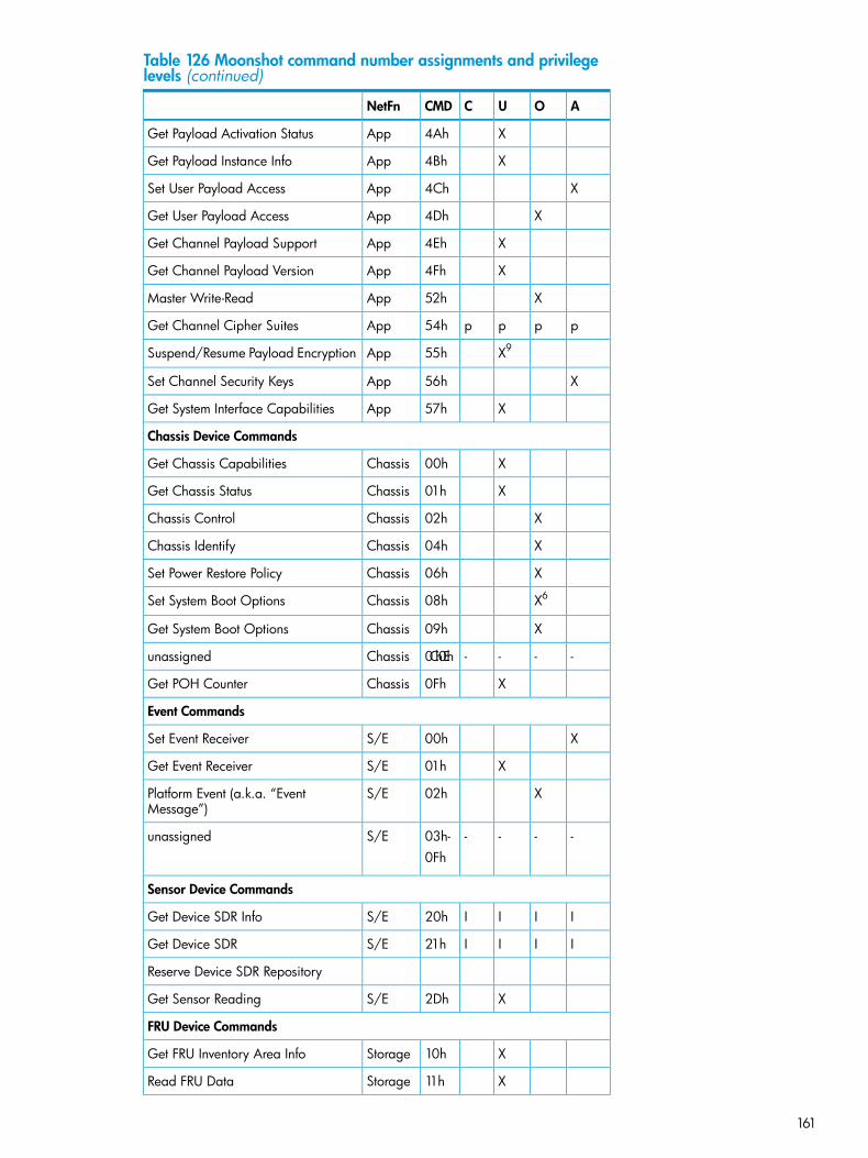
Table 126 Moonshot command number assignments and privilegelevels (continued)
AOUCCMDNetFn
X4AhAppGet Payload Activation Status
X4BhAppGet Payload Instance Info
X4ChAppSet User Payload Access
X4DhAppGet User Payload Access
X4EhAppGet Channel Payload Support
X4FhAppGet Channel Payload Version
X52hAppMaster Write-Read
pppp54hAppGet Channel Cipher Suites
X955hAppSuspend/Resume Payload Encryption
X56hAppSet Channel Security Keys
X57hAppGet System Interface Capabilities
Chassis Device Commands
X00hChassisGet Chassis Capabilities
X01hChassisGet Chassis Status
X02hChassisChassis Control
X04hChassisChassis Identify
X06hChassisSet Power Restore Policy
X608hChassisSet System Boot Options
X09hChassisGet System Boot Options
----0Ch-0EhChassisunassigned
X0FhChassisGet POH Counter
Event Commands
X00hS/ESet Event Receiver
X01hS/EGet Event Receiver
X02hS/EPlatform Event (a.k.a. “EventMessage”)
----03h-S/Eunassigned0Fh
Sensor Device Commands
IIII20hS/EGet Device SDR Info
IIII21hS/EGet Device SDR
Reserve Device SDR Repository
X2DhS/EGet Sensor Reading
FRU Device Commands
X10hStorageGet FRU Inventory Area Info
X11hStorageRead FRU Data
161

Table 126 Moonshot command number assignments and privilegelevels (continued)
AOUCCMDNetFn
X12hStorageWrite FRU Data
SDR Device Commands
X20hStorageGet SDR Repository Info
X21hStorageGet SDR Repository Allocation Info
X22hStorageReserve SDR Repository
X23hStorageGet SDR
X24hStorageAdd SDR
X26hStorageDelete SDR
X27hStorageClear SDR Repository
X2ChStorageRun Initialization Agent
SEL Device Commands
X40hStorageGet SEL Info
X42hStorageReserve SEL
X43hStorageGet SEL Entry
X44hStorageAdd SEL Entry
X47hStorageClear SEL
X48hStorageGet SEL Time
X49hStorageSet SEL Time
LAN Device Commands
X01hTransportSet LAN Configuration Parameters
X02hTransportGet LAN Configuration Parameters
Serial/Modem Device Commands
X21hTransportSet SOL Configuration Parameters
X22hTransportGet SOL Configuration Parameters
DCMI Specific
X01hDCGRP(2ch)
Get DCMI Capability Info
X06hDCGRP(2ch)
Get Asset Tag
X07hDCGRP(2ch)
Get DCMI Sensor Info
X08hDCGRP(2ch)
Set Asset Tag
X09hDCGRP(2ch)
Get Controller ID String
X0AhDCGRP(2ch)
Set Controller ID String
PICMG Specific
162 Command Assignments

Table 126 Moonshot command number assignments and privilegelevels (continued)
AOUCCMDNetFn
X00hPICMG(00h)
Get PICMG Properties
X01hPICMG(00h)
Get Address Info
X1FhPICMG(00h)
FRU Inventory Device Lock Control
1 This command is sent using the Broadcast format on IPMB. See command description for details.2 A User can use a Send Message command to deliver a message to system software, butOperator privilege is required to use it to access other channels.3 Command only applies to authenticated channels.4 This is effectively a no-op if the user has a maximum privilege limit of User since the commandcould not be used to change the operating privilege level to a higher value.5 A session operating at Callback, User, or Operator can only use this command to terminate theirown session. An Administrator or system software can use the command to terminate any session.6 There is a bit in this command that can only be set at Administrator privilege level7 Command available for all levels except for User level.8 See [ICMB] specification for command specifications9 The Suspend/Resume Payload Encryption command may be overridden by a configuration optionfor the particular payload type that forces encryption to be used. In this case, an Admin levelcommand would typically be required to change the configuration.10 The configuration parameters for a given payload type determine the privilege level requiredto activate/deactivate the payload.
163

B Verbose output examplesroot@JSMITH-LX:/# ipmitool -I lanplus -H ILOH101GEMINI -U Administrator -P password sdr list all –v
Running Get PICMG Properties my_addr 0x20, transit 0, target 0x20Discovered PICMG Extension 2.3Discovered IPMB-0 address 0x20Device ID : ZoMCEntity ID : 240.96 (PICMG Shelf Management Controller)Device Slave Address : 20hChannel Number : 0hACPI System P/S Notif : Not RequiredACPI Device P/S Notif : Not RequiredController Presence : StaticLogs Init Agent Errors : NoEvent Message Gen : EnableDevice CapabilitiesChassis Device : NoBridge : NoIPMB Event Generator : NoIPMB Event Receiver : YesFRU Inventory Device : YesSEL Device : YesSDR Repository : YesSensor Device : Yes
Device ID : 254Entity ID : 240.96 (PICMG Shelf Management Controller)Device Access Address : 20hLogical FRU Device : FEhChannel Number : 0hLUN.Bus : 0h.0hDevice Type.Modifier : 10h.0h (IPMI FRU Inventory)OEM : 00h
Sensor ID : IPMB0 Phys Link (0x1)Entity ID : 240.96 (PICMG Shelf Management Controller)Sensor Type (Discrete): PICMG IPMB0 Link State (0xf1)Sensor Reading : 0hEvent Message Control : No Events From SensorOEM : 0
Device ID : ChasMgmtCtlr1Entity ID : 23.1 (System Chassis)Device Slave Address : 44hChannel Number : 0hACPI System P/S Notif : Not RequiredACPI Device P/S Notif : Not RequiredController Presence : StaticLogs Init Agent Errors : NoEvent Message Gen : EnableDevice CapabilitiesChassis Device : YesBridge : NoIPMB Event Generator : YesIPMB Event Receiver : NoFRU Inventory Device : YesSEL Device : NoSDR Repository : YesSensor Device : Yes
Device ID : PsMgmtCtlr1Entity ID : 10.1 (Power Supply)Device Slave Address : 52hChannel Number : 0hACPI System P/S Notif : Not RequiredACPI Device P/S Notif : Not RequiredController Presence : DynamicLogs Init Agent Errors : NoEvent Message Gen : EnableDevice CapabilitiesChassis Device : NoBridge : NoIPMB Event Generator : YesIPMB Event Receiver : NoFRU Inventory Device : YesSEL Device : NoSDR Repository : YesSensor Device : Yes
Device ID : PsMgmtCtlr2Entity ID : 10.2 (Power Supply)Device Slave Address : 54hChannel Number : 0hACPI System P/S Notif : Not RequiredACPI Device P/S Notif : Not RequiredController Presence : DynamicLogs Init Agent Errors : NoEvent Message Gen : Enable
164 Verbose output examples

Device CapabilitiesChassis Device : NoBridge : NoIPMB Event Generator : YesIPMB Event Receiver : NoFRU Inventory Device : YesSEL Device : NoSDR Repository : YesSensor Device : Yes
Device ID : PsMgmtCtlr3Entity ID : 10.3 (Power Supply)Device Slave Address : 56hChannel Number : 0hACPI System P/S Notif : Not RequiredACPI Device P/S Notif : Not RequiredController Presence : DynamicLogs Init Agent Errors : NoEvent Message Gen : EnableDevice CapabilitiesChassis Device : NoBridge : NoIPMB Event Generator : YesIPMB Event Receiver : NoFRU Inventory Device : YesSEL Device : NoSDR Repository : YesSensor Device : Yes
Device ID : PsMgmtCtlr4Entity ID : 10.4 (Power Supply)Device Slave Address : 58hChannel Number : 0hACPI System P/S Notif : Not RequiredACPI Device P/S Notif : Not RequiredController Presence : DynamicLogs Init Agent Errors : NoEvent Message Gen : EnableDevice CapabilitiesChassis Device : NoBridge : NoIPMB Event Generator : YesIPMB Event Receiver : NoFRU Inventory Device : YesSEL Device : NoSDR Repository : YesSensor Device : Yes
Device ID : CaMCEntity ID : 160.97 (PICMG Front Board)Device Slave Address : A6hChannel Number : 0hACPI System P/S Notif : Not RequiredACPI Device P/S Notif : Not RequiredController Presence : DynamicLogs Init Agent Errors : NoEvent Message Gen : EnableDevice CapabilitiesChassis Device : NoBridge : NoIPMB Event Generator : YesIPMB Event Receiver : NoFRU Inventory Device : YesSEL Device : NoSDR Repository : YesSensor Device : Yes
Device ID : CaMCEntity ID : 160.97 (PICMG Front Board)Device Slave Address : A8hChannel Number : 0hACPI System P/S Notif : Not RequiredACPI Device P/S Notif : Not RequiredController Presence : DynamicLogs Init Agent Errors : NoEvent Message Gen : EnableDevice CapabilitiesChassis Device : NoBridge : NoIPMB Event Generator : YesIPMB Event Receiver : NoFRU Inventory Device : YesSEL Device : NoSDR Repository : YesSensor Device : Yes
Device ID : CaMCEntity ID : 160.97 (PICMG Front Board)Device Slave Address : AAhChannel Number : 0hACPI System P/S Notif : Not RequiredACPI Device P/S Notif : Not RequiredController Presence : Dynamic
165

Logs Init Agent Errors : NoEvent Message Gen : EnableDevice CapabilitiesChassis Device : NoBridge : NoIPMB Event Generator : YesIPMB Event Receiver : NoFRU Inventory Device : YesSEL Device : NoSDR Repository : YesSensor Device : Yes
Device ID : CaMCEntity ID : 160.97 (PICMG Front Board)Device Slave Address : AChChannel Number : 0hACPI System P/S Notif : Not RequiredACPI Device P/S Notif : Not RequiredController Presence : DynamicLogs Init Agent Errors : NoEvent Message Gen : EnableDevice CapabilitiesChassis Device : NoBridge : NoIPMB Event Generator : YesIPMB Event Receiver : NoFRU Inventory Device : YesSEL Device : NoSDR Repository : YesSensor Device : Yes
Device ID : CaMCEntity ID : 160.97 (PICMG Front Board)Device Slave Address : AEhChannel Number : 0hACPI System P/S Notif : Not RequiredACPI Device P/S Notif : Not RequiredController Presence : DynamicLogs Init Agent Errors : NoEvent Message Gen : EnableDevice CapabilitiesChassis Device : NoBridge : NoIPMB Event Generator : YesIPMB Event Receiver : NoFRU Inventory Device : YesSEL Device : NoSDR Repository : YesSensor Device : Yes
Device ID : CaMCEntity ID : 160.97 (PICMG Front Board)Device Slave Address : B0hChannel Number : 0hACPI System P/S Notif : Not RequiredACPI Device P/S Notif : Not RequiredController Presence : DynamicLogs Init Agent Errors : NoEvent Message Gen : EnableDevice CapabilitiesChassis Device : NoBridge : NoIPMB Event Generator : YesIPMB Event Receiver : NoFRU Inventory Device : YesSEL Device : NoSDR Repository : YesSensor Device : Yes
Device ID : CaMCEntity ID : 160.97 (PICMG Front Board)Device Slave Address : B2hChannel Number : 0hACPI System P/S Notif : Not RequiredACPI Device P/S Notif : Not RequiredController Presence : DynamicLogs Init Agent Errors : NoEvent Message Gen : EnableDevice CapabilitiesChassis Device : NoBridge : NoIPMB Event Generator : YesIPMB Event Receiver : NoFRU Inventory Device : YesSEL Device : NoSDR Repository : YesSensor Device : Yes
Device ID : CaMCEntity ID : 160.97 (PICMG Front Board)Device Slave Address : B8hChannel Number : 0hACPI System P/S Notif : Not Required
166 Verbose output examples

ACPI Device P/S Notif : Not RequiredController Presence : DynamicLogs Init Agent Errors : NoEvent Message Gen : EnableDevice CapabilitiesChassis Device : NoBridge : NoIPMB Event Generator : YesIPMB Event Receiver : NoFRU Inventory Device : YesSEL Device : NoSDR Repository : YesSensor Device : Yes
Device ID : CaMCEntity ID : 160.97 (PICMG Front Board)Device Slave Address : B4hChannel Number : 0hACPI System P/S Notif : Not RequiredACPI Device P/S Notif : Not RequiredController Presence : DynamicLogs Init Agent Errors : NoEvent Message Gen : EnableDevice CapabilitiesChassis Device : NoBridge : NoIPMB Event Generator : YesIPMB Event Receiver : NoFRU Inventory Device : YesSEL Device : NoSDR Repository : YesSensor Device : Yes
Device ID : CaMCEntity ID : 160.97 (PICMG Front Board)Device Slave Address : BAhChannel Number : 0hACPI System P/S Notif : Not RequiredACPI Device P/S Notif : Not RequiredController Presence : DynamicLogs Init Agent Errors : NoEvent Message Gen : EnableDevice CapabilitiesChassis Device : NoBridge : NoIPMB Event Generator : YesIPMB Event Receiver : NoFRU Inventory Device : YesSEL Device : NoSDR Repository : YesSensor Device : Yes
Device ID : CaMCEntity ID : 160.97 (PICMG Front Board)Device Slave Address : 82hChannel Number : 0hACPI System P/S Notif : Not RequiredACPI Device P/S Notif : Not RequiredController Presence : DynamicLogs Init Agent Errors : NoEvent Message Gen : EnableDevice CapabilitiesChassis Device : NoBridge : NoIPMB Event Generator : YesIPMB Event Receiver : NoFRU Inventory Device : YesSEL Device : NoSDR Repository : YesSensor Device : Yes
Device ID : CaMCEntity ID : 160.97 (PICMG Front Board)Device Slave Address : B6hChannel Number : 0hACPI System P/S Notif : Not RequiredACPI Device P/S Notif : Not RequiredController Presence : DynamicLogs Init Agent Errors : NoEvent Message Gen : EnableDevice CapabilitiesChassis Device : NoBridge : NoIPMB Event Generator : YesIPMB Event Receiver : NoFRU Inventory Device : YesSEL Device : NoSDR Repository : YesSensor Device : Yes
Device ID : CaMCEntity ID : 160.97 (PICMG Front Board)Device Slave Address : BCh
167

Channel Number : 0hACPI System P/S Notif : Not RequiredACPI Device P/S Notif : Not RequiredController Presence : DynamicLogs Init Agent Errors : NoEvent Message Gen : EnableDevice CapabilitiesChassis Device : NoBridge : NoIPMB Event Generator : YesIPMB Event Receiver : NoFRU Inventory Device : YesSEL Device : NoSDR Repository : YesSensor Device : Yes
Device ID : CaMCEntity ID : 160.97 (PICMG Front Board)Device Slave Address : 84hChannel Number : 0hACPI System P/S Notif : Not RequiredACPI Device P/S Notif : Not RequiredController Presence : DynamicLogs Init Agent Errors : NoEvent Message Gen : EnableDevice CapabilitiesChassis Device : NoBridge : NoIPMB Event Generator : YesIPMB Event Receiver : NoFRU Inventory Device : YesSEL Device : NoSDR Repository : YesSensor Device : Yes
Device ID : CaMCEntity ID : 160.97 (PICMG Front Board)Device Slave Address : BEhChannel Number : 0hACPI System P/S Notif : Not RequiredACPI Device P/S Notif : Not RequiredController Presence : DynamicLogs Init Agent Errors : NoEvent Message Gen : EnableDevice CapabilitiesChassis Device : NoBridge : NoIPMB Event Generator : YesIPMB Event Receiver : NoFRU Inventory Device : YesSEL Device : NoSDR Repository : YesSensor Device : Yes
Device ID : CaMCEntity ID : 160.97 (PICMG Front Board)Device Slave Address : 86hChannel Number : 0hACPI System P/S Notif : Not RequiredACPI Device P/S Notif : Not RequiredController Presence : DynamicLogs Init Agent Errors : NoEvent Message Gen : EnableDevice CapabilitiesChassis Device : NoBridge : NoIPMB Event Generator : YesIPMB Event Receiver : NoFRU Inventory Device : YesSEL Device : NoSDR Repository : YesSensor Device : Yes
Device ID : CaMCEntity ID : 160.97 (PICMG Front Board)Device Slave Address : C0hChannel Number : 0hACPI System P/S Notif : Not RequiredACPI Device P/S Notif : Not RequiredController Presence : DynamicLogs Init Agent Errors : NoEvent Message Gen : EnableDevice CapabilitiesChassis Device : NoBridge : NoIPMB Event Generator : YesIPMB Event Receiver : NoFRU Inventory Device : YesSEL Device : NoSDR Repository : YesSensor Device : Yes
Device ID : CaMC
168 Verbose output examples

Entity ID : 160.97 (PICMG Front Board)Device Slave Address : 88hChannel Number : 0hACPI System P/S Notif : Not RequiredACPI Device P/S Notif : Not RequiredController Presence : DynamicLogs Init Agent Errors : NoEvent Message Gen : EnableDevice CapabilitiesChassis Device : NoBridge : NoIPMB Event Generator : YesIPMB Event Receiver : NoFRU Inventory Device : YesSEL Device : NoSDR Repository : YesSensor Device : Yes
Device ID : CaMCEntity ID : 160.97 (PICMG Front Board)Device Slave Address : C2hChannel Number : 0hACPI System P/S Notif : Not RequiredACPI Device P/S Notif : Not RequiredController Presence : DynamicLogs Init Agent Errors : NoEvent Message Gen : EnableDevice CapabilitiesChassis Device : NoBridge : NoIPMB Event Generator : YesIPMB Event Receiver : NoFRU Inventory Device : YesSEL Device : NoSDR Repository : YesSensor Device : Yes
Device ID : CaMCEntity ID : 160.97 (PICMG Front Board)Device Slave Address : C4hChannel Number : 0hACPI System P/S Notif : Not RequiredACPI Device P/S Notif : Not RequiredController Presence : DynamicLogs Init Agent Errors : NoEvent Message Gen : EnableDevice CapabilitiesChassis Device : NoBridge : NoIPMB Event Generator : YesIPMB Event Receiver : NoFRU Inventory Device : YesSEL Device : NoSDR Repository : YesSensor Device : Yes
Device ID : CaMCEntity ID : 160.97 (PICMG Front Board)Device Slave Address : 8AhChannel Number : 0hACPI System P/S Notif : Not RequiredACPI Device P/S Notif : Not RequiredController Presence : DynamicLogs Init Agent Errors : NoEvent Message Gen : EnableDevice CapabilitiesChassis Device : NoBridge : NoIPMB Event Generator : YesIPMB Event Receiver : NoFRU Inventory Device : YesSEL Device : NoSDR Repository : YesSensor Device : Yes
Device ID : CaMCEntity ID : 160.97 (PICMG Front Board)Device Slave Address : C6hChannel Number : 0hACPI System P/S Notif : Not RequiredACPI Device P/S Notif : Not RequiredController Presence : DynamicLogs Init Agent Errors : NoEvent Message Gen : EnableDevice CapabilitiesChassis Device : NoBridge : NoIPMB Event Generator : YesIPMB Event Receiver : NoFRU Inventory Device : YesSEL Device : NoSDR Repository : YesSensor Device : Yes
169

Device ID : CaMCEntity ID : 160.97 (PICMG Front Board)Device Slave Address : 8ChChannel Number : 0hACPI System P/S Notif : Not RequiredACPI Device P/S Notif : Not RequiredController Presence : DynamicLogs Init Agent Errors : NoEvent Message Gen : EnableDevice CapabilitiesChassis Device : NoBridge : NoIPMB Event Generator : YesIPMB Event Receiver : NoFRU Inventory Device : YesSEL Device : NoSDR Repository : YesSensor Device : Yes
Device ID : CaMCEntity ID : 160.97 (PICMG Front Board)Device Slave Address : C8hChannel Number : 0hACPI System P/S Notif : Not RequiredACPI Device P/S Notif : Not RequiredController Presence : DynamicLogs Init Agent Errors : NoEvent Message Gen : EnableDevice CapabilitiesChassis Device : NoBridge : NoIPMB Event Generator : YesIPMB Event Receiver : NoFRU Inventory Device : YesSEL Device : NoSDR Repository : YesSensor Device : Yes
Device ID : CaMCEntity ID : 160.97 (PICMG Front Board)Device Slave Address : 8EhChannel Number : 0hACPI System P/S Notif : Not RequiredACPI Device P/S Notif : Not RequiredController Presence : DynamicLogs Init Agent Errors : NoEvent Message Gen : EnableDevice CapabilitiesChassis Device : NoBridge : NoIPMB Event Generator : YesIPMB Event Receiver : NoFRU Inventory Device : YesSEL Device : NoSDR Repository : YesSensor Device : Yes
Device ID : CaMCEntity ID : 160.97 (PICMG Front Board)Device Slave Address : 90hChannel Number : 0hACPI System P/S Notif : Not RequiredACPI Device P/S Notif : Not RequiredController Presence : DynamicLogs Init Agent Errors : NoEvent Message Gen : EnableDevice CapabilitiesChassis Device : NoBridge : NoIPMB Event Generator : YesIPMB Event Receiver : NoFRU Inventory Device : YesSEL Device : NoSDR Repository : YesSensor Device : Yes
Device ID : CaMCEntity ID : 160.97 (PICMG Front Board)Device Slave Address : CAhChannel Number : 0hACPI System P/S Notif : Not RequiredACPI Device P/S Notif : Not RequiredController Presence : DynamicLogs Init Agent Errors : NoEvent Message Gen : EnableDevice CapabilitiesChassis Device : NoBridge : NoIPMB Event Generator : YesIPMB Event Receiver : NoFRU Inventory Device : YesSEL Device : No
170 Verbose output examples

SDR Repository : YesSensor Device : Yes
Device ID : CaMCEntity ID : 160.97 (PICMG Front Board)Device Slave Address : CChChannel Number : 0hACPI System P/S Notif : Not RequiredACPI Device P/S Notif : Not RequiredController Presence : DynamicLogs Init Agent Errors : NoEvent Message Gen : EnableDevice CapabilitiesChassis Device : NoBridge : NoIPMB Event Generator : YesIPMB Event Receiver : NoFRU Inventory Device : YesSEL Device : NoSDR Repository : YesSensor Device : Yes
Device ID : CaMCEntity ID : 160.97 (PICMG Front Board)Device Slave Address : 92hChannel Number : 0hACPI System P/S Notif : Not RequiredACPI Device P/S Notif : Not RequiredController Presence : DynamicLogs Init Agent Errors : NoEvent Message Gen : EnableDevice CapabilitiesChassis Device : NoBridge : NoIPMB Event Generator : YesIPMB Event Receiver : NoFRU Inventory Device : YesSEL Device : NoSDR Repository : YesSensor Device : Yes
Device ID : CaMCEntity ID : 160.97 (PICMG Front Board)Device Slave Address : CEhChannel Number : 0hACPI System P/S Notif : Not RequiredACPI Device P/S Notif : Not RequiredController Presence : DynamicLogs Init Agent Errors : NoEvent Message Gen : EnableDevice CapabilitiesChassis Device : NoBridge : NoIPMB Event Generator : YesIPMB Event Receiver : NoFRU Inventory Device : YesSEL Device : NoSDR Repository : YesSensor Device : Yes
Device ID : CaMCEntity ID : 160.97 (PICMG Front Board)Device Slave Address : 94hChannel Number : 0hACPI System P/S Notif : Not RequiredACPI Device P/S Notif : Not RequiredController Presence : DynamicLogs Init Agent Errors : NoEvent Message Gen : EnableDevice CapabilitiesChassis Device : NoBridge : NoIPMB Event Generator : YesIPMB Event Receiver : NoFRU Inventory Device : YesSEL Device : NoSDR Repository : YesSensor Device : Yes
Device ID : CaMCEntity ID : 160.97 (PICMG Front Board)Device Slave Address : D0hChannel Number : 0hACPI System P/S Notif : Not RequiredACPI Device P/S Notif : Not RequiredController Presence : DynamicLogs Init Agent Errors : NoEvent Message Gen : EnableDevice CapabilitiesChassis Device : NoBridge : NoIPMB Event Generator : YesIPMB Event Receiver : No
171

FRU Inventory Device : YesSEL Device : NoSDR Repository : YesSensor Device : Yes
Device ID : CaMCEntity ID : 160.97 (PICMG Front Board)Device Slave Address : 96hChannel Number : 0hACPI System P/S Notif : Not RequiredACPI Device P/S Notif : Not RequiredController Presence : DynamicLogs Init Agent Errors : NoEvent Message Gen : EnableDevice CapabilitiesChassis Device : NoBridge : NoIPMB Event Generator : YesIPMB Event Receiver : NoFRU Inventory Device : YesSEL Device : NoSDR Repository : YesSensor Device : Yes
Device ID : CaMCEntity ID : 160.97 (PICMG Front Board)Device Slave Address : D2hChannel Number : 0hACPI System P/S Notif : Not RequiredACPI Device P/S Notif : Not RequiredController Presence : DynamicLogs Init Agent Errors : NoEvent Message Gen : EnableDevice CapabilitiesChassis Device : NoBridge : NoIPMB Event Generator : YesIPMB Event Receiver : NoFRU Inventory Device : YesSEL Device : NoSDR Repository : YesSensor Device : Yes
Device ID : CaMCEntity ID : 160.97 (PICMG Front Board)Device Slave Address : 98hChannel Number : 0hACPI System P/S Notif : Not RequiredACPI Device P/S Notif : Not RequiredController Presence : DynamicLogs Init Agent Errors : NoEvent Message Gen : EnableDevice CapabilitiesChassis Device : NoBridge : NoIPMB Event Generator : YesIPMB Event Receiver : NoFRU Inventory Device : YesSEL Device : NoSDR Repository : YesSensor Device : Yes
Device ID : CaMCEntity ID : 160.97 (PICMG Front Board)Device Slave Address : D4hChannel Number : 0hACPI System P/S Notif : Not RequiredACPI Device P/S Notif : Not RequiredController Presence : DynamicLogs Init Agent Errors : NoEvent Message Gen : EnableDevice CapabilitiesChassis Device : NoBridge : NoIPMB Event Generator : YesIPMB Event Receiver : NoFRU Inventory Device : YesSEL Device : NoSDR Repository : YesSensor Device : Yes
Device ID : CaMCEntity ID : 160.97 (PICMG Front Board)Device Slave Address : 9AhChannel Number : 0hACPI System P/S Notif : Not RequiredACPI Device P/S Notif : Not RequiredController Presence : DynamicLogs Init Agent Errors : NoEvent Message Gen : EnableDevice CapabilitiesChassis Device : NoBridge : No
172 Verbose output examples

IPMB Event Generator : YesIPMB Event Receiver : NoFRU Inventory Device : YesSEL Device : NoSDR Repository : YesSensor Device : Yes
Device ID : CaMCEntity ID : 160.97 (PICMG Front Board)Device Slave Address : D6hChannel Number : 0hACPI System P/S Notif : Not RequiredACPI Device P/S Notif : Not RequiredController Presence : DynamicLogs Init Agent Errors : NoEvent Message Gen : EnableDevice CapabilitiesChassis Device : NoBridge : NoIPMB Event Generator : YesIPMB Event Receiver : NoFRU Inventory Device : YesSEL Device : NoSDR Repository : YesSensor Device : Yes
Device ID : CaMCEntity ID : 160.97 (PICMG Front Board)Device Slave Address : 9ChChannel Number : 0hACPI System P/S Notif : Not RequiredACPI Device P/S Notif : Not RequiredController Presence : DynamicLogs Init Agent Errors : NoEvent Message Gen : EnableDevice CapabilitiesChassis Device : NoBridge : NoIPMB Event Generator : YesIPMB Event Receiver : NoFRU Inventory Device : YesSEL Device : NoSDR Repository : YesSensor Device : Yes
Device ID : CaMCEntity ID : 160.97 (PICMG Front Board)Device Slave Address : 9EhChannel Number : 0hACPI System P/S Notif : Not RequiredACPI Device P/S Notif : Not RequiredController Presence : DynamicLogs Init Agent Errors : NoEvent Message Gen : EnableDevice CapabilitiesChassis Device : NoBridge : NoIPMB Event Generator : YesIPMB Event Receiver : NoFRU Inventory Device : YesSEL Device : NoSDR Repository : YesSensor Device : Yes
Device ID : CaMCEntity ID : 160.97 (PICMG Front Board)Device Slave Address : D8hChannel Number : 0hACPI System P/S Notif : Not RequiredACPI Device P/S Notif : Not RequiredController Presence : DynamicLogs Init Agent Errors : NoEvent Message Gen : EnableDevice CapabilitiesChassis Device : NoBridge : NoIPMB Event Generator : YesIPMB Event Receiver : NoFRU Inventory Device : YesSEL Device : NoSDR Repository : YesSensor Device : Yes
Device ID : CaMCEntity ID : 160.97 (PICMG Front Board)Device Slave Address : A0hChannel Number : 0hACPI System P/S Notif : Not RequiredACPI Device P/S Notif : Not RequiredController Presence : DynamicLogs Init Agent Errors : NoEvent Message Gen : EnableDevice Capabilities
173

Chassis Device : NoBridge : NoIPMB Event Generator : YesIPMB Event Receiver : NoFRU Inventory Device : YesSEL Device : NoSDR Repository : YesSensor Device : Yes
Device ID : CaMCEntity ID : 160.97 (PICMG Front Board)Device Slave Address : DAhChannel Number : 0hACPI System P/S Notif : Not RequiredACPI Device P/S Notif : Not RequiredController Presence : DynamicLogs Init Agent Errors : NoEvent Message Gen : EnableDevice CapabilitiesChassis Device : NoBridge : NoIPMB Event Generator : YesIPMB Event Receiver : NoFRU Inventory Device : YesSEL Device : NoSDR Repository : YesSensor Device : Yes
Device ID : CaMCEntity ID : 160.97 (PICMG Front Board)Device Slave Address : A2hChannel Number : 0hACPI System P/S Notif : Not RequiredACPI Device P/S Notif : Not RequiredController Presence : DynamicLogs Init Agent Errors : NoEvent Message Gen : EnableDevice CapabilitiesChassis Device : NoBridge : NoIPMB Event Generator : YesIPMB Event Receiver : NoFRU Inventory Device : YesSEL Device : NoSDR Repository : YesSensor Device : Yes
Device ID : CaMCEntity ID : 160.97 (PICMG Front Board)Device Slave Address : A4hChannel Number : 0hACPI System P/S Notif : Not RequiredACPI Device P/S Notif : Not RequiredController Presence : DynamicLogs Init Agent Errors : NoEvent Message Gen : EnableDevice CapabilitiesChassis Device : NoBridge : NoIPMB Event Generator : YesIPMB Event Receiver : NoFRU Inventory Device : YesSEL Device : NoSDR Repository : YesSensor Device : Yes
At cartridge:root@JSMITH-LX:/# ipmitool -I lanplus -H ILOH101GEMINI -U Administrator -P password -t 0xa4 sdr list all -v
Running Get PICMG Properties my_addr 0x20, transit 0, target 0x20Discovered PICMG Extension 2.3Discovered IPMB-0 address 0x20Discovered Target IPMB-0 address 0xa4Sensor ID : 01-Front Ambient (0x1)Entity ID : 64.97 (Air Inlet)Sensor Type (Threshold) : Temperature (0x01)Sensor Reading : 21 (+/- 0) degrees CStatus : okPositive Hysteresis : UnspecifiedNegative Hysteresis : UnspecifiedMinimum sensor range : -127.000Maximum sensor range : UnspecifiedEvent Message Control : Entire Sensor OnlyReadable Thresholds : ucr unr Settable Thresholds : Threshold Read Mask : ucr unr
Sensor ID : 02-CPU (0x2)Entity ID : 65.97 (Processor)Sensor Type (Threshold) : Temperature (0x01)Sensor Reading : 40 (+/- 0) degrees CStatus : ok
174 Verbose output examples

Positive Hysteresis : UnspecifiedNegative Hysteresis : UnspecifiedMinimum sensor range : -127.000Maximum sensor range : UnspecifiedEvent Message Control : Entire Sensor OnlyReadable Thresholds : ucr unr Settable Thresholds : Threshold Read Mask : ucr unr
Sensor ID : 03-DIMM (0x3)Entity ID : 32.97 (Memory Device)Sensor Type (Threshold) : Temperature (0x01)Sensor Reading : 26 (+/- 0) degrees CStatus : okPositive Hysteresis : UnspecifiedNegative Hysteresis : UnspecifiedMinimum sensor range : -127.000Maximum sensor range : UnspecifiedEvent Message Control : Entire Sensor OnlyReadable Thresholds : ucr unr Settable Thresholds : Threshold Read Mask : ucr unr
Sensor ID : 04-Cart Ctrlr (0x4)Entity ID : 66.97 (Baseboard/Main System Board)Sensor Type (Threshold) : Temperature (0x01)Sensor Reading : 24 (+/- 0) degrees CStatus : okPositive Hysteresis : UnspecifiedNegative Hysteresis : UnspecifiedMinimum sensor range : -127.000Maximum sensor range : UnspecifiedEvent Message Control : Entire Sensor OnlyReadable Thresholds : ucr unr Settable Thresholds : Threshold Read Mask : ucr unr
Sensor ID : 05-CPU Zone (0x5)Entity ID : 66.98 (Baseboard/Main System Board)Sensor Type (Threshold) : Temperature (0x01)Sensor Reading : 29 (+/- 0) degrees CStatus : okPositive Hysteresis : UnspecifiedNegative Hysteresis : UnspecifiedMinimum sensor range : -127.000Maximum sensor range : UnspecifiedEvent Message Control : Entire Sensor OnlyReadable Thresholds : ucr unr Settable Thresholds : Threshold Read Mask : ucr unr
Sensor ID : 06-LOM Zone (0x6)Entity ID : 66.99 (Baseboard/Main System Board)Sensor Type (Threshold) : Temperature (0x01)Sensor Reading : 36 (+/- 0) degrees CStatus : okPositive Hysteresis : UnspecifiedNegative Hysteresis : UnspecifiedMinimum sensor range : -127.000Maximum sensor range : UnspecifiedEvent Message Control : Entire Sensor OnlyReadable Thresholds : ucr unr Settable Thresholds : Threshold Read Mask : ucr unr
Device ID : CaMCEntity ID : 160.97 (PICMG Front Board)Device Slave Address : A4hChannel Number : 0hACPI System P/S Notif : Not RequiredACPI Device P/S Notif : Not RequiredController Presence : DynamicLogs Init Agent Errors : NoEvent Message Gen : EnableDevice CapabilitiesChassis Device : NoBridge : NoIPMB Event Generator : YesIPMB Event Receiver : NoFRU Inventory Device : YesSEL Device : NoSDR Repository : YesSensor Device : Yes
Device ID : SnMCEntity ID : 193.97 (PICMG AdvancedMC Module)Device Slave Address : 72hChannel Number : 7hACPI System P/S Notif : Not RequiredACPI Device P/S Notif : Not RequiredController Presence : DynamicLogs Init Agent Errors : NoEvent Message Gen : Enable
175

Device CapabilitiesChassis Device : NoBridge : NoIPMB Event Generator : YesIPMB Event Receiver : NoFRU Inventory Device : YesSEL Device : YesSDR Repository : YesSensor Device : Yes
Device ID : SnMC 1Entity ID : 193.98 (PICMG AdvancedMC Module)Device Access Address : A4hLogical FRU Device : 01hChannel Number : 0hLUN.Bus : 0h.0hDevice Type.Modifier : 10h.0h (IPMI FRU Inventory)OEM : 00h
root@JSMITH-LX:/# ipmitool -I lanplus -H ILOH101GEMINI -U Administrator -P password sel list -v
Running Get PICMG Properties my_addr 0x20, transit 0, target 0x20Discovered PICMG Extension 2.3Discovered IPMB-0 address 0x20SEL Record ID : 0000Record Type : 02Timestamp : 02/23/2000 21:29:38Generator ID : 0044EvM Revision : 04Sensor Type : Power SupplySensor Number : 04Event Type : Sensor-specific DiscreteEvent Direction : Assertion EventEvent Data : 01ffffDescription : Failure detected
SEL Record ID : 0001Record Type : 02Timestamp : 02/28/2000 21:57:58Generator ID : 0044EvM Revision : 04Sensor Type : Power SupplySensor Number : 04Event Type : Sensor-specific DiscreteEvent Direction : Assertion EventEvent Data : 01ffffDescription : Failure detected
SEL Record ID : 0002Record Type : 02Timestamp : 03/06/2000 11:11:14Generator ID : 0044EvM Revision : 04Sensor Type : Power SupplySensor Number : 04Event Type : Sensor-specific DiscreteEvent Direction : Assertion EventEvent Data : 01ffffDescription : Failure detected
SEL Record ID : 0003Record Type : 02Timestamp : 03/17/2000 01:52:47Generator ID : 0044EvM Revision : 04Sensor Type : Power SupplySensor Number : 04Event Type : Sensor-specific DiscreteEvent Direction : Assertion EventEvent Data : 01ffffDescription : Failure detected
SEL Record ID : 0004Record Type : 02Timestamp : 03/24/2000 03:07:30Generator ID : 0044EvM Revision : 04Sensor Type : Power SupplySensor Number : 04Event Type : Sensor-specific DiscreteEvent Direction : Assertion EventEvent Data : 01ffffDescription : Failure detected
176 Verbose output examples

SEL Record ID : 0005Record Type : 02Timestamp : 03/27/2000 01:23:36Generator ID : 0044EvM Revision : 04Sensor Type : Power SupplySensor Number : 04Event Type : Sensor-specific DiscreteEvent Direction : Assertion EventEvent Data : 01ffffDescription : Failure detected
SEL Record ID : 0006Record Type : 02Timestamp : 03/27/2000 03:00:34Generator ID : 0044EvM Revision : 04Sensor Type : Power SupplySensor Number : 04Event Type : Sensor-specific DiscreteEvent Direction : Assertion EventEvent Data : 01ffffDescription : Failure detected
SEL Record ID : 0007Record Type : 02Timestamp : 03/27/2000 08:42:18Generator ID : 0044EvM Revision : 04Sensor Type : Power SupplySensor Number : 02Event Type : Sensor-specific DiscreteEvent Direction : Assertion EventEvent Data : 01ffffDescription : Failure detected
SEL Record ID : 0008Record Type : 02Timestamp : 03/27/2000 08:42:18Generator ID : 0044EvM Revision : 04Sensor Type : Power SupplySensor Number : 03Event Type : Sensor-specific DiscreteEvent Direction : Assertion EventEvent Data : 01ffffDescription : Failure detected
SEL Record ID : 0009Record Type : 02Timestamp : 03/27/2000 08:42:18Generator ID : 0044EvM Revision : 04Sensor Type : Power SupplySensor Number : 04Event Type : Sensor-specific DiscreteEvent Direction : Assertion EventEvent Data : 01ffffDescription : Failure detected
SEL Record ID : 000aRecord Type : 02Timestamp : 03/27/2000 20:58:04Generator ID : 0044EvM Revision : 04Sensor Type : Power SupplySensor Number : 04Event Type : Sensor-specific DiscreteEvent Direction : Assertion EventEvent Data : 01ffffDescription : Failure detected
SEL Record ID : 000bRecord Type : 02Timestamp : 04/04/2000 22:19:34Generator ID : 0044EvM Revision : 04Sensor Type : Power SupplySensor Number : 02Event Type : Sensor-specific DiscreteEvent Direction : Assertion Event
177

Event Data : 01ffffDescription : Failure detected
SEL Record ID : 000cRecord Type : 02Timestamp : 04/04/2000 22:19:36Generator ID : 0044EvM Revision : 04Sensor Type : Power SupplySensor Number : 03Event Type : Sensor-specific DiscreteEvent Direction : Assertion EventEvent Data : 01ffffDescription : Failure detected
SEL Record ID : 000dRecord Type : 02Timestamp : 04/04/2000 22:19:36Generator ID : 0044EvM Revision : 04Sensor Type : Power SupplySensor Number : 04Event Type : Sensor-specific DiscreteEvent Direction : Assertion EventEvent Data : 01ffffDescription : Failure detected
SEL Record ID : 000eRecord Type : 02Timestamp : 04/04/2000 22:19:36Generator ID : 0044EvM Revision : 04Sensor Type : Power SupplySensor Number : 05Event Type : Sensor-specific DiscreteEvent Direction : Assertion EventEvent Data : 01ffffDescription : Failure detected
SEL Record ID : 000fRecord Type : 02Timestamp : 04/07/2000 01:33:48Generator ID : 0044EvM Revision : 04Sensor Type : Power SupplySensor Number : 04Event Type : Sensor-specific DiscreteEvent Direction : Assertion EventEvent Data : 01ffffDescription : Failure detected
SEL Record ID : 0010Record Type : 02Timestamp : 04/07/2000 01:37:33Generator ID : 0044EvM Revision : 04Sensor Type : Power SupplySensor Number : 04Event Type : Sensor-specific DiscreteEvent Direction : Assertion EventEvent Data : 01ffffDescription : Failure detected
SEL Record ID : 0011Record Type : 02Timestamp : 04/16/2013 20:22:01Generator ID : 0044EvM Revision : 04Sensor Type : Power SupplySensor Number : 04Event Type : Sensor-specific DiscreteEvent Direction : Assertion EventEvent Data : 01ffffDescription : Failure detected
SEL Record ID : 0012Record Type : 02Timestamp : 04/16/2013 21:23:09Generator ID : 0044EvM Revision : 04Sensor Type : Power Supply
178 Verbose output examples

Sensor Number : 04Event Type : Sensor-specific DiscreteEvent Direction : Assertion EventEvent Data : 01ffffDescription : Failure detected
SEL Record ID : 0013Record Type : 02Timestamp : 04/18/2013 13:24:19Generator ID : 0044EvM Revision : 04Sensor Type : Power SupplySensor Number : 04Event Type : Sensor-specific DiscreteEvent Direction : Assertion EventEvent Data : 01ffffDescription : Failure detected
SEL Record ID : 0014Record Type : 02Timestamp : 04/18/2013 13:36:11Generator ID : 0044EvM Revision : 04Sensor Type : Power SupplySensor Number : 02Event Type : Sensor-specific DiscreteEvent Direction : Assertion EventEvent Data : 01ffffDescription : Failure detected
SEL Record ID : 0015Record Type : 02Timestamp : 04/22/2013 15:54:30Generator ID : 0044EvM Revision : 04Sensor Type : Power SupplySensor Number : 04Event Type : Sensor-specific DiscreteEvent Direction : Assertion EventEvent Data : 01ffffDescription : Failure detected
SEL Record ID : 0016Record Type : 02Timestamp : 06/26/2013 21:57:07Generator ID : 0044EvM Revision : 04Sensor Type : Power SupplySensor Number : 04Event Type : Sensor-specific DiscreteEvent Direction : Assertion EventEvent Data : 01ffffDescription : Failure detected
SEL Record ID : 0017Record Type : 02Timestamp : 06/27/2013 18:17:54Generator ID : 0044EvM Revision : 04Sensor Type : Power SupplySensor Number : 04Event Type : Sensor-specific DiscreteEvent Direction : Assertion EventEvent Data : 01ffffDescription : Failure detected
SEL Record ID : 0018Record Type : 02Timestamp : 06/28/2013 20:36:17Generator ID : 0044EvM Revision : 04Sensor Type : Power SupplySensor Number : 02Event Type : Sensor-specific DiscreteEvent Direction : Deassertion EventEvent Data : 00ffffDescription : Presence detected
SEL Record ID : 0019Record Type : 02Timestamp : 07/28/2013 00:20:52
179

Generator ID : 0044EvM Revision : 04Sensor Type : Power SupplySensor Number : 02Event Type : Sensor-specific DiscreteEvent Direction : Assertion EventEvent Data : 01ffffDescription : Failure detected
SEL Record ID : 001aRecord Type : 02Timestamp : 08/04/2013 00:23:10Generator ID : 0044EvM Revision : 04Sensor Type : Power SupplySensor Number : 02Event Type : Sensor-specific DiscreteEvent Direction : Deassertion EventEvent Data : 00ffffDescription : Presence detected
SEL Record ID : 001bRecord Type : 02Timestamp : 08/06/2013 15:05:21Generator ID : 0044EvM Revision : 04Sensor Type : Power SupplySensor Number : 03Event Type : Sensor-specific DiscreteEvent Direction : Assertion EventEvent Data : 01ffffDescription : Failure detected
SEL Record ID : 001cRecord Type : 02Timestamp : 08/06/2013 15:05:22Generator ID : 0044EvM Revision : 04Sensor Type : Power SupplySensor Number : 04Event Type : Sensor-specific DiscreteEvent Direction : Assertion EventEvent Data : 01ffffDescription : Failure detected
SEL Record ID : 001dRecord Type : 02Timestamp : 08/06/2013 15:05:22Generator ID : 0044EvM Revision : 04Sensor Type : Power SupplySensor Number : 05Event Type : Sensor-specific DiscreteEvent Direction : Assertion EventEvent Data : 01ffffDescription : Failure detected
SEL Record ID : 001eRecord Type : 02Timestamp : 08/06/2013 15:05:26Generator ID : 0044EvM Revision : 04Sensor Type : Power SupplySensor Number : 02Event Type : Sensor-specific DiscreteEvent Direction : Assertion EventEvent Data : 01ffffDescription : Failure detected
SEL Record ID : 001fRecord Type : 02Timestamp : 08/09/2013 14:34:48Generator ID : 0044EvM Revision : 04Sensor Type : FanSensor Number : 07Event Type : Generic DiscreteEvent Direction : Assertion EventEvent Data : 04ffffDescription : Transition to Off Line
180 Verbose output examples

SEL Record ID : 0020Record Type : 02Timestamp : 08/09/2013 14:34:49Generator ID : 0044EvM Revision : 04Sensor Type : FanSensor Number : 07Event Type : Generic DiscreteEvent Direction : Deassertion EventEvent Data : 00ffffDescription : Transition to Running
SEL Record ID : 0021Record Type : 02Timestamp : 08/09/2013 14:34:53Generator ID : 0044EvM Revision : 04Sensor Type : FanSensor Number : 07Event Type : Generic DiscreteEvent Direction : Assertion EventEvent Data : 00ffffDescription : Transition to Running
SEL Record ID : 0022Record Type : 02Timestamp : 08/09/2013 14:35:11Generator ID : 0044EvM Revision : 04Sensor Type : FanSensor Number : 09Event Type : Generic DiscreteEvent Direction : Assertion EventEvent Data : 04ffffDescription : Transition to Off Line
SEL Record ID : 0023Record Type : 02Timestamp : 08/09/2013 14:35:11Generator ID : 0044EvM Revision : 04Sensor Type : FanSensor Number : 09Event Type : Generic DiscreteEvent Direction : Deassertion EventEvent Data : 00ffffDescription : Transition to Running
SEL Record ID : 0024Record Type : 02Timestamp : 08/09/2013 14:35:16Generator ID : 0044EvM Revision : 04Sensor Type : FanSensor Number : 09Event Type : Generic DiscreteEvent Direction : Assertion EventEvent Data : 00ffffDescription : Transition to Running
SEL Record ID : 0025Record Type : 02Timestamp : 08/09/2013 14:35:21Generator ID : 0044EvM Revision : 04Sensor Type : FanSensor Number : 08Event Type : Generic DiscreteEvent Direction : Assertion EventEvent Data : 04ffffDescription : Transition to Off Line
SEL Record ID : 0026Record Type : 02Timestamp : 08/09/2013 14:35:21Generator ID : 0044EvM Revision : 04Sensor Type : FanSensor Number : 08Event Type : Generic DiscreteEvent Direction : Deassertion Event
181

Event Data : 00ffffDescription : Transition to Running
SEL Record ID : 0027Record Type : 02Timestamp : 08/09/2013 14:36:09Generator ID : 0044EvM Revision : 04Sensor Type : FanSensor Number : 09Event Type : Generic DiscreteEvent Direction : Assertion EventEvent Data : 04ffffDescription : Transition to Off Line
SEL Record ID : 0028Record Type : 02Timestamp : 08/09/2013 14:36:09Generator ID : 0044EvM Revision : 04Sensor Type : FanSensor Number : 09Event Type : Generic DiscreteEvent Direction : Deassertion EventEvent Data : 00ffffDescription : Transition to Running
SEL Record ID : 0029Record Type : 02Timestamp : 08/09/2013 14:36:14Generator ID : 0044EvM Revision : 04Sensor Type : FanSensor Number : 09Event Type : Generic DiscreteEvent Direction : Assertion EventEvent Data : 00ffffDescription : Transition to Running
SEL Record ID : 002aRecord Type : 02Timestamp : 08/09/2013 14:36:31Generator ID : 0044EvM Revision : 04Sensor Type : FanSensor Number : 08Event Type : Generic DiscreteEvent Direction : Assertion EventEvent Data : 00ffffDescription : Transition to Running
SEL Record ID : 002bRecord Type : 02Timestamp : 08/09/2013 14:36:45Generator ID : 0044EvM Revision : 04Sensor Type : FanSensor Number : 0aEvent Type : Generic DiscreteEvent Direction : Assertion EventEvent Data : 04ffffDescription : Transition to Off Line
SEL Record ID : 002cRecord Type : 02Timestamp : 08/09/2013 14:36:45Generator ID : 0044EvM Revision : 04Sensor Type : FanSensor Number : 0aEvent Type : Generic DiscreteEvent Direction : Deassertion EventEvent Data : 00ffffDescription : Transition to Running
SEL Record ID : 002dRecord Type : 02Timestamp : 08/09/2013 14:36:50Generator ID : 0044EvM Revision : 04Sensor Type : Fan
182 Verbose output examples

Sensor Number : 0aEvent Type : Generic DiscreteEvent Direction : Assertion EventEvent Data : 00ffffDescription : Transition to Running
SEL Record ID : 002eRecord Type : 02Timestamp : 08/09/2013 14:36:52Generator ID : 0044EvM Revision : 04Sensor Type : FanSensor Number : 0bEvent Type : Generic DiscreteEvent Direction : Assertion EventEvent Data : 04ffffDescription : Transition to Off Line
SEL Record ID : 002fRecord Type : 02Timestamp : 08/09/2013 14:36:52Generator ID : 0044EvM Revision : 04Sensor Type : FanSensor Number : 0bEvent Type : Generic DiscreteEvent Direction : Deassertion EventEvent Data : 00ffffDescription : Transition to Running
SEL Record ID : 0030Record Type : 02Timestamp : 08/09/2013 14:36:57Generator ID : 0044EvM Revision : 04Sensor Type : FanSensor Number : 0bEvent Type : Generic DiscreteEvent Direction : Assertion EventEvent Data : 00ffffDescription : Transition to Running
SEL Record ID : 0031Record Type : 02Timestamp : 08/09/2013 14:43:23Generator ID : 0044EvM Revision : 04Sensor Type : FanSensor Number : 08Event Type : Generic DiscreteEvent Direction : Assertion EventEvent Data : 04ffffDescription : Transition to Off Line
SEL Record ID : 0032Record Type : 02Timestamp : 08/09/2013 14:43:23Generator ID : 0044EvM Revision : 04Sensor Type : FanSensor Number : 08Event Type : Generic DiscreteEvent Direction : Deassertion EventEvent Data : 00ffffDescription : Transition to Running
SEL Record ID : 0033Record Type : 02Timestamp : 08/09/2013 14:43:54Generator ID : 0044EvM Revision : 04Sensor Type : FanSensor Number : 08Event Type : Generic DiscreteEvent Direction : Assertion EventEvent Data : 00ffffDescription : Transition to Running
SEL Record ID : 0034Record Type : 02Timestamp : 08/09/2013 14:49:46
183

Generator ID : 0044EvM Revision : 04Sensor Type : FanSensor Number : 0aEvent Type : Generic DiscreteEvent Direction : Assertion EventEvent Data : 04ffffDescription : Transition to Off Line
SEL Record ID : 0035Record Type : 02Timestamp : 08/09/2013 14:49:46Generator ID : 0044EvM Revision : 04Sensor Type : FanSensor Number : 0aEvent Type : Generic DiscreteEvent Direction : Deassertion EventEvent Data : 00ffffDescription : Transition to Running
SEL Record ID : 0036Record Type : 02Timestamp : 08/09/2013 14:49:55Generator ID : 0044EvM Revision : 04Sensor Type : FanSensor Number : 0aEvent Type : Generic DiscreteEvent Direction : Assertion EventEvent Data : 00ffffDescription : Transition to Running
SEL Record ID : 0037Record Type : 02Timestamp : 08/09/2013 14:50:12Generator ID : 0044EvM Revision : 04Sensor Type : FanSensor Number : 08Event Type : Generic DiscreteEvent Direction : Assertion EventEvent Data : 04ffffDescription : Transition to Off Line
SEL Record ID : 0038Record Type : 02Timestamp : 08/09/2013 14:50:12Generator ID : 0044EvM Revision : 04Sensor Type : FanSensor Number : 08Event Type : Generic DiscreteEvent Direction : Deassertion EventEvent Data : 00ffffDescription : Transition to Running
SEL Record ID : 0039Record Type : 02Timestamp : 08/09/2013 14:50:31Generator ID : 0044EvM Revision : 04Sensor Type : FanSensor Number : 08Event Type : Generic DiscreteEvent Direction : Assertion EventEvent Data : 00ffffDescription : Transition to Running
SEL Record ID : 003aRecord Type : 02Timestamp : 08/09/2013 15:00:54Generator ID : 0044EvM Revision : 04Sensor Type : FanSensor Number : 0bEvent Type : Generic DiscreteEvent Direction : Assertion EventEvent Data : 04ffffDescription : Transition to Off Line
184 Verbose output examples

SEL Record ID : 003bRecord Type : 02Timestamp : 08/09/2013 15:00:54Generator ID : 0044EvM Revision : 04Sensor Type : FanSensor Number : 0bEvent Type : Generic DiscreteEvent Direction : Deassertion EventEvent Data : 00ffffDescription : Transition to Running
SEL Record ID : 003cRecord Type : 02Timestamp : 08/09/2013 15:01:03Generator ID : 0044EvM Revision : 04Sensor Type : FanSensor Number : 0bEvent Type : Generic DiscreteEvent Direction : Assertion EventEvent Data : 00ffffDescription : Transition to Running
SEL Record ID : 003dRecord Type : 02Timestamp : 08/09/2013 15:01:30Generator ID : 0044EvM Revision : 04Sensor Type : FanSensor Number : 08Event Type : Generic DiscreteEvent Direction : Assertion EventEvent Data : 04ffffDescription : Transition to Off Line
SEL Record ID : 003eRecord Type : 02Timestamp : 08/09/2013 15:01:30Generator ID : 0044EvM Revision : 04Sensor Type : FanSensor Number : 08Event Type : Generic DiscreteEvent Direction : Deassertion EventEvent Data : 00ffffDescription : Transition to Running
SEL Record ID : 003fRecord Type : 02Timestamp : 08/09/2013 15:02:05Generator ID : 0044EvM Revision : 04Sensor Type : FanSensor Number : 08Event Type : Generic DiscreteEvent Direction : Assertion EventEvent Data : 00ffffDescription : Transition to Running
185
GlossaryACPI Advanced Configuration and Power Interface SpecificationBCD Binary-coded DecimalBMC Baseboard Management ControllerBT Block TransferChMC Chassis Management ControllerCMOS The PC-AT compatible region of battery-backed 128 bytes of memory, which normally resides
on the baseboardCTS Clear to sendDCD Data Carrier DetectDCMI Data Center Manageability InterfaceDSR Data Set ReadyDTR Data Transfer RequestEvMRev Event message revisionFPGA Field-Programmable Gate ArrayFRB Fault-resilient bootingFRU Field replaceable unitGUID Globally Unique IDHA High availabilityI2C Inter-Integrated Circuit
IANA Internet Assigned Numbers AuthorityICMB Intelligent Chassis Management BusIERR Internal errorIPMB Intelligent Platform Management BusIPMI Intelligent Platform Management InterfaceKCS Keyboard Controller StyleLPC Low Pin CountLS Least significant byteMC Management ControllerMS Most significant bytemux multiplexingNAK Negative-acknowledge characterNetFn Network FunctionNMI Non-maskable InterruptPCI Peripheral Component InterconnectPEF Platform Event FilteringPICMG PCI Industrial Computer Manufacturers GroupPOH Power-On HoursPSMC Power Supply Management ControllerRAKP Remote Authenticated Key-Exchange ProtocolRMCP Remote Management Control ProtocolRQ Received requestRS Received response
186 Glossary

rsSA Random Single Switch AlgorithmRTS Request to sendSCI Software Configuration IdentificationSDR Sensor Data RecordSEL System Event LogSMB System Management BusSMI System Management InterruptSMIC System Management Interface ChipSMM System Management Mode.SMS System Management SoftwareSOL Serial Over LANSSI Server System InfrastructureSSIF SMBus System InterfaceSWID Software IDTAP Telocator Access ProtocolUUID Universally Unique IDentifierVSO VITA Standards Organization
187
Index
AACK messages, 155active sessions, 57authcode, 59authentication, 144authorized resellers, 157
BBMC, 141
interfaces, 141BT, 19
Cchannel access, 66channel accessibility, 65channel number, 144chassis status, 22command line tool, 18command set, 141command value, 141Commands
Get Sensor Reading, 7commands
Activate Session, 144activate session, 56add sel entry, 114CMD, 141get channel access limits, 65Get Channel Info, 145Get Device ID, 17Get SDR, 11Get SDR Repository Info, 11Get Session, 144Master Write-Read, 12Read/Write FRU, 12SEEPROM, 12set channel access, 56set user access, 56verbose, 21
completion code, 142completion condition, 142configure channels, 60contacting HP, 157
Ddata block, 59device discovery, 17dynamic controllers, 17
Eevent receiver, 114events, 21
FFRU, 11
data, 11inventory device, 12
function codes, 141function command, 140
Hhandshake
per block, 140per byte, 140
helpobtaining, 157
HPtechnical support, 157
IICMB, 141inventory
remote, 22IPMI
capabilities, 7definition, 7
IPMI LAN session, 156IPMItool, 18
definition, 18discovery of features, 20encryption, 19LANplus interface, 19remote chassis power control, 18
IPMV, 141IPv4, 19
KKCS, 140, 141
LLAN, 141LANPlus interface
RMCP+, 19Linux
kernal driver, 19OpenIPMI, 23
Mmessage interface, 141message payload, 140micro-controller, 140
NNetFn, 140network function code, 140
OOpenIPMI, 19OpenSSL, 19
188 Index

Pparsing hierarchy, 141payload commands, 70POH counter, 12print field replaceable unit, 18privilege level, 65
RRCMP+, 70remote systems, 22response messages, 142RMCP, 154, 155RMCP+ protocol, 156
SSDR
format, 10platform management, 10purpose, 10record body, 10record header, 10record key, 10repository, 10repository device, 12
SEL, 114SEL commands, 114SEL device, 114
SEL commands, 9Sensor data model, 7sensor data repository, 18sensor owner
sensor owner id, 7sensor type codes, 8serial/modem, 141session, 144session-less, 144SMCI, 141SOL, 156Solaris
BMC, 23SSIF, 140Support and other resources, 157system interface, 19
Ttechnical support
HP, 157timers
POH counter, 12Watchdog, 12
timestampformat, 12values, 12
Uuser id, 69user password, 69
Vvirtual chassis manager, 17
189