hp color laserjet enterprise flow mfp m880 and hp color ... · event log errors do not appear on...
TRANSCRIPT

HP Color LaserJet Enterprise Flow MFP
M880 and HP Color LaserJet Enterprise
M855 - Control Panel Message Document
(CPMD)
Control-panel message types
The control-panel messages and event code entries indicate the current product status or
situations that might require action.
Note:
Event log errors do not appear on the control-panel display. Open the event log to view or print
the event log errors.
A control-panel message displays temporarily and might require the user to acknowledge the
message by touching the OK button to resume printing or by touching the Stop button to cancel
the job. With certain messages, the job might not finish printing or the print quality might be
affected. If the message is related to printing and the auto-continue feature is on, the product will
attempt to resume printing after the message has appeared for 10 seconds without
acknowledgement.
For some messages, restarting the product might fix the problem. If a critical error persists, the
product might require service.
Printer service information
Last update: 10/09/2017
Service mode PIN numbers:
• M855: 11085513
• flow MFP 880: 11088013
Note:
When possible, always update the printer firmware to the latest available version at HP.com as
part of the troubleshooting performed for any of the following errors. After the firmware updates,
re-enable auto send through the control panel
10. WX.YZ error messages
10.* error messages
Errors in the 10.* family are related to toner cartridges and other supply items that require
regular replacement as part of routine printer maintenance.
The customer is expected to order replacement supplies and install them as necessary. Use the
following list to identify the supply item affected:
Note:

Not all printers have all of these supplies.
• 10.00.XX = Black toner cartridge
• 10.01.XX = Cyan toner cartridge
• 10.02.XX = Magenta toner cartridge
• 10.03.XX = Yellow toner cartridge
• 10.22.XX = Transfer kit
• 10.23.XX = Fuser kit
• 10.31.XX = Toner collection unit
• 10.39.XX = Document feeder kit
• 10.99.XX = One or more supply items have been installed
Recommended action
Use the following general troubleshooting steps to try to resolve the problem. If the error
persists, elevate the case using the Standard Support Process.
1. For toner cartridges:
1. Remove and reinstall the cartridge.
2. Check the supplies memory chip. If it is damaged, replace the toner cartridge.
3. If print quality is unacceptable, or if printing cannot continue, replace the toner
cartridge.
2. For the transfer kit:
1. Remove and then reinstall the transfer unit.
2. If print quality is unacceptable, or if printing cannot continue, replace the transfer
kit.
3. For the fuser kit:
1. Remove and then reinstall the fuser.
Caution:
The fuser might be hot.
2. If print quality is unacceptable, or if printing cannot continue, replace the fuser
kit.
4. For the toner collection unit:
1. Remove the toner collection unit and reinstall it.
2. If the toner collection unit is nearly full, replace it with a new one. Using a toner
collection unit until it is overfilled can damage the printer.
5. For the document feeder kit:
1. Open the document feeder top cover and inspect the rollers for obvious dirt or
wear. Clean the rollers if necessary.
2. Install a new roller kit.
10.0X.00 e-Label Memory Error
The printer is unable to read the toner cartridge or imaging drum memory tag data and a
‘10.0X.00 <color> toner cartridge’ error or ‘10.0X.00 <color> image drum’ error occurs.
10.00.00 Black toner cartridge

10.01.00 Cyan toner cartridge
10.02.00 Magenta toner cartridge
10.03.00 Yellow toner cartridge
10.05.00 Black image drum
10.06.00 Cyan image drum
10.07.00 Magenta image drum
10.08.00 Yellow image drum
This message indicates that the printer has determined that it cannot read or write to one of the e-
labels on the toner cartridge or imaging drum.
Caused when the toner cartridge or imaging drum is present but defective.
This error can cause the supplies status feature to become disabled.
Recommended action
1. Open the front door and remove the toner cartridge or imaging drum.
2. Check the e-label. If it is damaged, replace the toner cartridge or imaging drum.
o Black toner drum part number: CF358A
o Cyan toner drum part number: CF359A
o Yellow toner drum part number: CF364A
o Magenta toner drum part number: CF365A
o Black toner cartridge part number (M855): CF310A
o Cyan toner cartridge part number (M855): CF311A
o Yellow toner cartridge part number (M855): CF312A
o Magenta toner cartridge part number (M855): CF313A
o Black toner cartridge part number (M880): CF300A
o Cyan toner cartridge part number (M880): CF301A
o Yellow toner cartridge part number (M880): CF302A
o Magenta toner cartridge part number (M880): CF303A
3. Reinstall the toner cartridge or imaging drum and close the front door.
4. If the error persists, turn the printer off, and then on.
5. If the error persists, replace the memory tag PCA.
Part number: RM2-7009-000CN
6. If the error persists, replace the DC controller.
For instructions: See the Repair Service Manual for this product.
M855 part number: RM2-7005-000CN
M880 part number: RM2-7006-000CN
7. If the error persists, replace the cartridge interface PCA that corresponds to the
combination of colors giving the issue.
Part number: A2W79-67902

10.0X.10 e-Label Missing Memory Error
The printer is unable to detect one or more of the e-labels.
This error can cause the supplies status feature to become disabled.
When this error occurs, a question mark appears on the gas gauge of the supply or supplies with
the error.
If multiple supplies have this error, a 10.0X.10 error for the first supply detected with the error
displays. After the user resolves the error that corresponds to the first supply, another 10.0X.Y0
error displays for the next supply. This continues for all supplies memory errors.
10.00.10 Black toner cartridge
10.01.10 Cyan toner cartridge
10.02.10 Magenta toner cartridge
10.03.10 Yellow toner cartridge
10.05.10 Black imaging drum
10.06.10 Cyan imaging drum
10.07.10 Magenta imaging drum
10.08.10 Yellow imaging drum
Recommended action
1. Open the front door and remove the toner cartridge or the imaging drum.
2. Check the e-label on the supply. If it is damaged, replace the toner cartridge or imaging
drum.
o Black toner drum part number: CF358A
o Cyan toner drum part number: CF359A
o Yellow toner drum part number: CF364A
o Magenta toner drum part number: CF365A
o Black toner cartridge part number (M855): CF310A
o Cyan toner cartridge part number (M855): CF311A
o Yellow toner cartridge part number (M855): CF312A
o Magenta toner cartridge part number (M855): CF313A
o Black toner cartridge part number (M880): CF300A
o Cyan toner cartridge part number (M880): CF301A
o Yellow toner cartridge part number (M880): CF302A
o Magenta toner cartridge part number (M880): CF303A
3. Reinstall the toner cartridge or imaging drum, and then close the front door.
4. If the error persists, replace the memory tag PCA.
Part number: RM2-7009-000CN
5. If the error persists, replace the DC controller.
For instructions: See the Repair Service Manual for this product.
M855 part number: RM2-7005-000CN
M880 part number: RM2-7006-000CN

6. If the error persists, replace the cartridge interface PCA that corresponds to the
combination of colors giving the issue.
Part number: A2W79-67902
10.0X.15 Install <supply> (event code)
The indicated supply has been removed or is installed incorrectly.
10.00.15 Black toner cartridge (event code)
10.01.15 Cyan toner cartridge (event code)
10.02.15 Magenta toner cartridge (event code)
10.03.15 Yellow toner cartridge (event code)
10.23.15 Fuser kit (event code)
10.31.15 Toner collection unit (TCU) (event code)
Recommended action
1. Remove and reinstall the indicated supply, and ensure that it is seated correctly.
2. If the error persists, replace the fuser kit, toner cartridge, toner collection kit (toner drum
or ITB), or other indicated supply.
o For instructions: Removal and replacement: Fuser
Fuser (110V) part number: C1N54-67901
o Fuser (220V) part number: C1N58-67901
o For instructions: Removal and replacement: ITB_Transfer roller
ITB unit part number: A2W77-67904
o Black toner drum part number: CF358A
o Cyan toner drum part number: CF359A
o Yellow toner drum part number: CF364A
o Magenta toner drum part number: CF365A
o Black toner cartridge part number (M855): CF310A
o Cyan toner cartridge part number (M855): CF311A
o Yellow toner cartridge part number (M855): CF312A
o Magenta toner cartridge part number (M855): CF313A
o Black toner cartridge part number (M880): CF300A
o Cyan toner cartridge part number (M880): CF301A
o Yellow toner cartridge part number (M880): CF302A
o Magenta toner cartridge part number (M880): CF303A
10.0X.25 Wrong cartridge in <color> slot
The indicated toner cartridge is installed in the wrong position.
10.00.25 Black toner cartridge (event code)
10.01.25 Cyan toner cartridge (event code)
10.02.25 Magenta toner cartridge (event code)
10.03.25 Yellow toner cartridge (event code)

Recommended action
1. Install the indicated cartridge in the correct position. From left to right, the correct
cartridge order is as follows:
o Yellow
o Magenta
o Cyan
o Black
10.0X.34 Used Supply in use
The indicated toner cartridge is used.
10.00.34 Black toner cartridge (event code)
10.01.34 Cyan toner cartridge (event code)
10.02.34 Magenta toner cartridge (event code)
10.03.34 Yellow toner cartridge (event code)
Recommended action
1. Ensure that the toner cartridge is a genuine HP supply.
Note:
Removing a toner cartridge from one printer and then installing it in a different
printer (for testing functionality) will cause this message and event code.
10.0X.35 Incompatible <supply>
The indicated supply is not compatible with this printer.
10.00.35 Black toner cartridge (event code)
10.01.35 Cyan toner cartridge (event code)
10.02.35 Magenta toner cartridge (event code)
10.03.35 Yellow toner cartridge (event code)
Recommended action
Install a supply that is designed for this printer.
10.0X.40 Genuine HP supplies installed
More than one genuine HP toner cartridge has been installed.
10.00.40 Black toner cartridge (event code)
10.01.40 Cyan toner cartridge (event code)
10.02.40 Magenta toner cartridge (event code)
10.03.40 Yellow toner cartridge (event code)
Recommended action
1. No action necessary.
10.0X.41 Unsupported Supply in use
The indicated toner cartridge is for a different printer.
10.00.41 Black toner cartridge (event code)
10.01.41 Cyan toner cartridge (event code)
10.02.41 Magenta toner cartridge (event code)

10.03.41 Yellow toner cartridge (event code)
Recommended action
1. Remove the indicated supply, and then install the correct supply for this printer.
10.0X.60 <Supply> low
The printer indicates when a supply level is low. Actual toner cartridge life might vary. You do
not need to replace the toner cartridge at this time unless print quality is no longer acceptable.
The 10.WX.60 is an event log only message, it will not show on the control panel. The only
message to display will be <Supply> low.
• 10.00.60 Black toner cartridge (event code)
• 10.01.60 Cyan toner cartridge (event code)
• 10.02.60 Magenta toner cartridge (event code)
• 10.03.60 Yellow toner cartridge (event code)
• 10.05.60 Black imaging drum event code)
• 10.06.60 Cyan imaging drum very low (event code)
• 10.07.60 Magenta imaging drum very low (event code)
• 10.08.60 Yellow imaging drum very low (event code)
Recommended action
1. If the print quality is no longer acceptable, replace the toner cartridge or imaging drum.
Note:
HP recommends having replacement supplies available to install when the print
quality is no longer acceptable.
o Black toner drum part number: CF358A
o Cyan toner drum part number: CF359A
o Yellow toner drum part number: CF364A
o Magenta toner drum part number: CF365A
o Black toner cartridge part number (M855): CF310A
o Cyan toner cartridge part number (M855): CF311A
o Yellow toner cartridge part number (M855): CF312A
o Magenta toner cartridge part number (M855): CF313A
o Black toner cartridge part number (M880): CF300A
o Cyan toner cartridge part number (M880): CF301A
o Yellow toner cartridge part number (M880): CF302A
o Magenta toner cartridge part number (M880): CF303A
10.0X.69 <Supply> very low
The printer indicates when a supply level is very low. Actual toner cartridge life might vary.
Consider having a replacement toner cartridge available to install when print quality is no longer

acceptable. You do not need to replace the toner cartridge at this time unless the print quality is
no longer acceptable.
The 10.WX.69 is an event log only message, it will not show on the control panel. The only
message to display will be <Supply> very low.
• 10.00.69 Black toner cartridge very low (event code)
• 10.01.69 Cyan toner cartridge very low (event code)
• 10.02.69 Magenta toner cartridge very low (event code)
• 10.03.69 Yellow toner cartridge very low (event code)
• 10.05.69 Black imaging drum event code)
• 10.06.69 Cyan imaging drum very low (event code)
• 10.07.69 Magenta imaging drum very low (event code)
• 10.08.69 Yellow imaging drum very low (event code)
Recommended action
1. If the print quality is no longer acceptable, replace the toner cartridge or imaging drum.
Note:
HP recommends having replacement supplies available to install when the print
quality is no longer acceptable.
o Black toner drum part number: CF358A
o Cyan toner drum part number: CF359A
o Yellow toner drum part number: CF364A
o Magenta toner drum part number: CF365A
o Black toner cartridge part number (M855): CF310A
o Cyan toner cartridge part number (M855): CF311A
o Yellow toner cartridge part number (M855): CF312A
o Magenta toner cartridge part number (M855): CF313A
o Black toner cartridge part number (M880): CF300A
o Cyan toner cartridge part number (M880): CF301A
o Yellow toner cartridge part number (M880): CF302A
o Magenta toner cartridge part number (M880): CF303A
10.0X.70 printing past very low
The printer indicates when one of the supplies is very low. The actual remaining supply life
might vary. You do not need to replace the toner cartridge at this time unless the print quality is
no longer acceptable.
The 10.WX.70 is an event log only message, it will not show on the control panel. The only
message to display will be a warning message <Supply> very low.
10.00.70 Black toner cartridge very low (event code)
10.01.70 Cyan toner cartridge (event code)
10.02.70 Magenta toner cartridge (event code)
10.03.70 Yellow toner cartridge (event code)
10.05.70 Black imaging drum very low (event code)
10.06.70 Cyan imaging drum (event code)
10.07.70 Magenta imaging drum (event code)
10.08.70 Yellow imaging drum (event code)
Recommended action
1. If the print quality is no longer acceptable, the customer must purchase and replace the
toner cartridge or imaging drum.
Note:
HP recommends having replacement supplies available to install when the print
quality is no longer acceptable.
o Black toner drum part number: CF358A
o Cyan toner drum part number: CF359A
o Yellow toner drum part number: CF364A
o Magenta toner drum part number: CF365A
o Black toner cartridge part number (M855): CF310A
o Cyan toner cartridge part number (M855): CF311A
o Yellow toner cartridge part number (M855): CF312A
o Magenta toner cartridge part number (M855): CF313A
o Black toner cartridge part number (M880): CF300A
o Cyan toner cartridge part number (M880): CF301A
o Yellow toner cartridge part number (M880): CF302A
o Magenta toner cartridge part number (M880): CF303A
10.0X.90 or 10.0X.91 <Color> cartridge error
A problem has occurred with the indicated toner cartridge.
10.0X.90 — a toner replenishment malfunction occurred and the toner concentration in the
imaging drum dropped below 30%. This applies to both HP and non-HP toner cartridges.
OR
The error occurs when the toner cartridge has been used past the end-of-life to the point the
reservoir in the imaging drum no longer has enough toner to safely continue printing.
10.0X.91 Toner cartridge motor stall.
Cause 1
The toner gate located on the toner cartridge or imaging drum might be out of synchronization.
The correct position of the gates for all supplies is closed when the toner cartridges or imaging
drums are out of the printer.
If one of the gates is in the open position when the cartridge or drum is out of the printer, then
that gate will close when installing the cartridge or drum into the printer. This will cause the
toner to not flow from the toner cartridge into the imaging drum and a 10.WX.90 or 10.WX.91
error message gets generated.
Note:
The 10.XY.90 message is expected behavior that occurs normally when the toner cartridge is
used in a past Very Low or 'Over Ride' condition. In this case, the message indicates that the
toner cartridge must be replaced. If the 10.XY.90 error has been generated as a result of running
the toner cartridge beyond a very low state, then the issue is not considered a warranty or defect
issue. Inform the customer that they must order and pay for a new toner cartridge. Do not
troubleshoot further.
Cause 2
The toner seal inside the toner cartridge or imaging drum fails to get removed automatically. No
toner will flow from the toner cartridges or no toner will get into the imaging drum.
10.00.90 Black toner cartridge (event code)
10.01.90 Cyan toner cartridge (event code)
10.02.90 Magenta toner cartridge (event code)
10.03.90 Yellow toner cartridge (event code)
10.00.91 Black toner cartridge (event code)
10.01.91 Cyan toner cartridge (event code)
10.02.91 Magenta toner cartridge (event code)
10.03.91 Yellow toner cartridge (event code)
Recommended action for customers
1. From the Home screen on the control panel, touch Supplies.
2. Verify that the Very low message is present (a yellow triangle with an exclamation point
inside).
3. If the cartridge level status is Not Very low, skip to the next step. If the level status of a
supply is Very low, replace the toner cartridge or imaging drum.
Note:
The supply replacement should correct the error and no further troubleshooting is
necessary.
o Black toner drum part number: CF358A
o Cyan toner drum part number: CF359A
o Yellow toner drum part number: CF364A
o Magenta toner drum part number: CF365A
o Black toner cartridge part number (M855): CF310A
o Cyan toner cartridge part number (M855): CF311A
o Yellow toner cartridge part number (M855): CF312A
o Magenta toner cartridge part number (M855): CF313A
o Black toner cartridge part number (M880): CF300A
o Cyan toner cartridge part number (M880): CF301A
o Yellow toner cartridge part number (M880): CF302A
o Magenta toner cartridge part number (M880): CF303A
4. Go to this support document: HP Color LaserJet Enterprise M855 and HP Color LaserJet
Enterprise flow M880 Multifunction Printers - 10.0x.90 and 10.0x.91 Errors
Recommended action for call agents
Recommended action for on-site technicians
1. Check the event log for active low warnings.
Note:
The 10.XY.90 message is expected behavior that occurs normally when the toner
cartridge is used in a past Very Low or 'Over Ride' condition. In this case, the
message indicates that the toner cartridge must be replaced. If the 10.XY.90 error
has been generated as a result of running the toner cartridge beyond a very low
state, then the issue is not considered a warranty or defect issue. Inform the
customer that they must order and pay for a new toner cartridge. Do not
troubleshoot further.
2. Check the printer toner cartridge and imaging drum slots for excessive toner spill and use
a toner vacuum to clean the area as needed.
3. Replace toner cartridge and imaging drum for the color that is causing the issue.
o Black toner drum part number: CF358A
o Cyan toner drum part number: CF359A
o Yellow toner drum part number: CF364A
o Magenta toner drum part number: CF365A
o Black toner cartridge part number (M855): CF310A
o Cyan toner cartridge part number (M855): CF311A
o Yellow toner cartridge part number (M855): CF312A
o Magenta toner cartridge part number (M855): CF313A
o Black toner cartridge part number (M880): CF300A
o Cyan toner cartridge part number (M880): CF301A
o Yellow toner cartridge part number (M880): CF302A
o Magenta toner cartridge part number (M880): CF303A
4. If replacing the imaging drum does not resolve the problem, replace the cartridge
interface PCA.
Part number: A2W79-67902
10.0X.92 Cartridge Error
Toner cartridge not engaged.
10.00.92 Black toner cartridge (event log)
10.01.92 Cyan toner cartridge (event log)
10.02.92 Magenta toner cartridge (event log)
10.03.92 Yellow toner cartridge (event log)
Recommended action
1. Open the front door, remove and reinstall the specified toner cartridge.
2. Check the toner cartridge for any damage or defects.
3. Replace toner cartridge.
10.22.60 Transfer Kit low, 10.22.69 Transfer Kit very low
The transfer kit estimated usage life is low or very low.
Recommended action

1. Check the event log for the 10.22.70 code. If this error is listed, the transfer kit is past
very low. The customer (at a minimum) must order and pay for a replacement
intermediate transfer belt (ITB). However, HP recommends that the customer order and
install a maintenance kit at this time.
2. Replace the ITB kit when the print quality becomes unacceptable.
For instructions: Removal and replacement: ITB_Transfer roller
Part number: D7H14-67902
Kit includes ITB, transfer roller and tray rollers.
Note:
HP recommends having replacement supplies available to install when the print
quality is no longer acceptable.
10.22.70 Transfer Kit Printing past very low
The transfer kit estimated usage life is very low.
Recommended action
1. Replace the ITB.
Note:
If print quality is no longer acceptable, the customer (at a minimum) must order
and pay for a replacement intermediate transfer belt (ITB). However, HP
recommends that the customer order and install a maintenance kit at this time.
For instructions: Removal and replacement: ITB_Transfer roller
Part number: D7H14-67902
Kit includes ITB, transfer roller and tray rollers.
Note:
HP recommends having replacement supplies available to install when the print
quality is no longer acceptable.
10.23.15 Install Fuser kit
The fuser is either not installed, or not installed correctly in the printer.
Recommended action
1. Remove, and then reinstall the fuser.
Caution:

The fuser might be hot.
2. Make sure that the fuser is seated correctly.
10.23.35 Incompatible Supply Fuser Kit
The indicated supply is not compatible with this printer.
Recommended action
Install a supply that is designed for this printer.
10.23.60 Fuser Kit low, 10.23.60 Fuser Kit very low
The fuser kit remaining usage life is low.
Recommended action
1. Check the event log for the 10.23.70 code.
o If a 10.23.70 error is listed, the fuser kit is past very low. Inform the customer that
they must order and pay for the replacement.
o If an active low warning is not listed, replace the part under warranty.
Note:
When an HP supply has reached the very low threshold, the HP Premium
Protection Warranty ends and the customer becomes responsible for the
replacement.
2. Replace the fuser.
For instructions: Removal and replacement: Fuser
Fuser (110V) part number: C1N54-67901
Fuser (220V) part number: C1N58-67901
3. Reset the fuser page counter by selecting New Fuser Kit in the Reset Supplies menu.
Note:
HP recommends having replacement supplies available to install when the print
quality is no longer acceptable.
10.23.70 Printing Past Very Low Fuser Kit
The printer indicates when the fuser kit is at its estimated end of life. The actual life remaining
might be different than the estimation. Have a replacement fuser kit available to install when
print quality is no longer acceptable.
Recommended action
1. Replace the fuser.
For instructions: Removal and replacement: Fuser

Fuser (110V) part number: C1N54-67901
Fuser (220V) part number: C1N58-67901
2. After replacing the fuser kit, select New Fuser Kit in the Reset Supplies menu to reset the
fuser page counter.
10.39.50 New Document Feeder Kit
A new document feeder maintenance kit has been installed and New Document Feeder Kit has
been selected from the control panel menus.
Recommended action
1. No action necessary.
10.39.53 ADF kit clean rollers recommended
Document feeder kit recommend clean prompt.
Recommended action
1. Remove the document feeder pick roller, feed roller, and the separation pad assemblies.
2. Clean the rollers and pad with a damp lint free cloth.
3. Reinstall the document feeder pick roller, feed roller, and the separation pad assemblies.
10.39.55 Clean Document Feeder Rollers
The document feeder separation pad and rollers need to be cleaned.
Recommended action
1. Remove the document feeder pick roller, feed roller, and the separation pad assemblies.
2. Clean the rollers and pad with a damp lint free cloth.
3. Reinstall the document feeder pick roller, feed roller, and the separation pad assemblies.
10.39.56
Scanned past document feeder scheduled cleaning prompt.
Recommended action
1. Remove the document feeder pick roller, feed roller, and the separation pad assemblies.
2. Clean the rollers and pad with a damp lint free cloth.
3. Reinstall the document feeder pick roller, feed roller, and the separation pad assemblies.
10.39.60 Document Feeder Kit low
The document feeder pick roller, feed roller, and separation pad are near their end of life.
Recommended action
1. No action necessary.
10.39.69 Document Feeder Kit very low
The document feeder pick roller, feed roller, and separation pad are at their end of life.

Recommended action
1. Order and install a document feeder maintenance kit.
Part number: C1P70A
10.39.70 scanning past very low
The document feeder pick roller, feed roller, and separation pad are at their end of life.
Recommended action
1. The customer must order and install a document feeder maintenance kit.
Part number: C1P70A
Note:
HP recommends having replacement supplies available to install when the print
quality is no longer acceptable.
10.39.71 Document Feeder has stopped
The document feeder pick roller, feed roller, and separation pad are at their end of life.
Recommended action
1. The customer must order and install a document feeder maintenance kit.
Part number: C1P70A
Note:
HP recommends having replacement supplies available to install when the print
quality is no longer acceptable.
10.99.31 Non-HP supply in use or Used supply in use
A non-HP supply (a remanufactured or refilled genuine HP or non-HP supply) has been
installed.
The 10.99.31 is an event log only message, it will not show on the control panel. The only
message to display will be used supply in use
Recommended action
1. The toner cartridge or imaging drum has been previously used. Touch OK to continue.
Note:
Removing a cartridge from one printer and then installing it in a different printer
(for testing functionality) will cause this event code.
Note:

If the customer purchased a genuine HP supply, go to
www.hp.com/go/anticounterfeit.
10.99.34 Used supply in use
A non-HP supply (a remanufactured or refilled genuine HP or non-HP supply) has been
installed.
The 10.99.34 is an event log only message, it will not show on the control panel. The only
message to display will be used supply in use.
Recommended action
1. The toner cartridge has been previously used. Touch OK to continue.
Note:
Removing a cartridge from one printer and then installing it in a different printer
(for testing functionality) will cause this event code.
Note:
If the customer purchased a genuine HP supply, go to
www.hp.com/go/anticounterfeit.
10.99.40 Genuine HP supplies installed
A new toner cartridge or imaging drum has been installed and all toner cartridges or imaging
drums are Genuine HP supplies.
Recommended action
1. Touch the OK to continue.
10.99.41 Unsupported Supply in use
The indicated toner cartridge or imaging drum is for a different printer.
Recommended action
1. Remove the indicated toner cartridge or imaging drum, and then install the correct toner
cartridge or imaging drum for the printer.
10.99.91 Cartridge motor stall, no particular cartridge
Cartridge motor is stalled.
Recommended action
1. If the error persists, run the component test for the imaging drum motor.
2. If the test fails, replace the imaging drum.
o Black toner drum part number: CF358A
o Cyan toner drum part number: CF359A
o Yellow toner drum part number: CF364A
o Magenta toner drum part number: CF365A
3. If the test passes, replace the toner cartridge.

o Black toner cartridge part number (M855): CF310A
o Cyan toner cartridge part number (M855): CF311A
o Yellow toner cartridge part number (M855): CF312A
o Magenta toner cartridge part number (M855): CF313A
o Black toner cartridge part number (M880): CF300A
o Cyan toner cartridge part number (M880): CF301A
o Yellow toner cartridge part number (M880): CF302A
o Magenta toner cartridge part number (M880): CF303A
11. WX.YZ error messages
11.* errors
Errors in the 11.* family are related to the printer real-time clock.
Recommended action
Use the following general troubleshooting steps to try to resolve the problem. If the error
persists, elevate the case using the Standard Support Process.
1. Set the time and date on the printer control panel.
2. If the error persists, remove and reinstall the formatter. Make sure it is fully seated.
3. If the error still persists, replace the formatter.
11.00.01 or 11.00.02 internal clock error
This message indicates a problem with the real time clock in the formatter.
The real time clock in the printer has experienced an error.
• 01= dead clock
• 02= dead real time clock
Recommended action
1. Turn the printer off, and then on.
2. Set the time and date on the control panel.
3. If the error persists, replace the formatter.
Note:
Do not replace the formatter, the DC controller, and the hard disk drive during a
single product servicing. Doing so might cause the printer to become unstable or
inoperable.
For instructions: Removal and replacement: Formatter
Part number formatter PCA assembly (M855): A2W77-67902
Part number formatter PCA Assembly (M880): A2W75-67903
Part number formatter PCA Assembly (M855 China/India ONLY): A2W77-67903

Part number formatter PCA Assembly (M880 China/India ONLY): A2W75-67902
13. WX.YZ error messages
13.* errors
Errors in the 13.* family are related to jams.
More than 1000 unique error codes are possible. Use the following information to understand the
jam code. Not all codes apply to all printers.
Message format: 13.WX.YZ
• W represents the jam location.
• X represents the sensor or door that triggered the jam.
• Y represents the jam condition (delay, stay, wrap, etc.)
• Z represents the paper source, fuser mode, or destination
Potential values for W and X
W Jam location X Sensor or door 0 Envelope feeder
1 Tray 1 feed (unless Tray 1 feed is the
registration sensor)
2 Tray 2 feed (unless Tray 2 feed is the
registration sensor) 3 Tray 3 feed 4 Tray 4 feed 5 Tray 5 feed 6 Tray 6 feed 7 Optional tray exit sensor A Door 1 B Door 2 C Door 3 D Door 4 E Door 5 F Multiple sensors or doors
B Image area 0 Media sensor for forbidden transparencies 2 Registration/top of page 3 Top of page 4 Loop 5 Fuser input 9 Fuser output A Door 1 B Door 2 F Multiple sensors or doors

Potential values for W and X
W Jam location X Sensor or door
C Switchback area (between the fuser and the
output bin) 1 Intermediate switchback sensor
2 Switchback media stay sensor 3 Paper delivery sensor
D Duplex area 1 Duplex switchback 2 Duplex delivery 3 Duplex refeed A Door 1 (if different than the imaging area) B Door 2 (if different than the imaging area) F Multiple sensors or doors
E Output or intermediate paper transport unit
(IPTU) area 1 Output bin full sensor
2 IPTU feed sensor 1 3 IPTU sensor 2 4 IPTU sensor 3 5 IPTU bin full sensor 4 6 Output sensor A Door 1 F Multiple sensors or doors
F Multiple subsystems (occurs when paper is
stuck in several areas) F Multiple sensors or doors
1 Jetlink input device 4 Tray 4 feed sensor 5 Tray 5 feed sensor 6 Tray 6 feed sensor 7 Tray 7 feed sensor 8 Tray 8 feed sensor 9 Tray 9 feed sensor A Door 1 B Door 2 F Multiple sensors or doors
2 Buffer pass unit 0 Buffer pass inlet sensor 9 Buffer pass exit sensor A Door 1
3 Page insert unit 0 Page insertion inlet sensor 1 Page insertion tray 1 feed sensor 2 Page insertion tray 2 feed sensor 3 Page insertion tray 3 feed sensor

Potential values for W and X
W Jam location X Sensor or door 4 Page insertion tray 4 feed sensor 7 Output path feed sensor 9 Page insertion exit sensor A Door 1
4 Punch unit 0 Puncher inlet sensor 1 Puncher jam sensor 9 Puncher exit sensor A Door 1
5 Folding unit 0 Folder inlet sensor 1 Folder sensor 9 Folder exit sensor A Door 1
6 Stacker unit 0 Stacker inlet sensor 4 Stacker outlet sensor 7 Stacker switchback entrance sensor 8 Stacker switchback registration sensor 9 Stacker switchback lower sensor
7 Multi-bin mailbox (MBM) unit 0 MBM inlet sensor 1 MBM middle sensor 9 Stapler sensor A Door 1 B Door 2 C Door 3 F Multiple sensors or doors
8 Stapler/stacker (SS) unit 0 SS inlet sensor 1 SS Bin Z 3 SS unit middle sensor 4 SS unit outlet sensor 1 5 SS unit outlet sensor 2 9 Stapler sensor A Door 1 B Door 2
9 Booklet maker unit 0 Booklet maker input sensor 2 Booklet maker feed sensor 2 2 Booklet maker feed sensor 3 4 Booklet maker delivery sensor

Potential values for W and X
W Jam location X Sensor or door 5 Booklet maker vertical paper path sensor 6 Booklet unit front staple sensor 7 Booklet unit rear staple sensor 8 Booklet unit outlet sensor A Door 1 B Door 2 C Door 3 F Multiple sensors or doors
0 Unknown 0 Unknown
Potential values for Y (jam condition)
Y Jam condition
0 Unknown
1 Unexpected sheet (duplex)
2 Staple jam
3 Jam caused by an open door (duplex)
4 Stay jam (the page never left the tray – duplex)
A Stay jam (the page never left the tray – simplex)
B Multifeed
C Wrap
D Delay (the page did not reach the sensor within the expected time –
simplex)
E Door open
F Residual (paper is detected in the paper path when it should not be
there)
The information represented by the value for Z depends on where the paper is in the paper path.
Potential values for Z (source, fuser mode, or destination)
Paper location Z Source, fuser mode, or destination
When paper has not reached the fuser, Z
represents the paper source. 1 Tray 1
2 Tray 2 3 Tray 3 4 Tray 4 5 Tray 5 6 Tray 6 D Duplexer E Envelope feeder

Potential values for Z (source, fuser mode, or destination)
Paper location Z Source, fuser mode, or destination
When paper has reached the fuser, is in the
duplex path, or in the output path, Z represents
the fuser mode.
Jams can occur when there is a mismatch
between the actual paper and the fuser mode
setting.
0 Photo 1, 2, or 3
Designated 2 or 3
1
Normal (automatically sensed rather than
based on the paper type set at the control
panel)
2 Normal (based on the paper type set at the
control panel) 3 Light 1, 2, or 3 4 Heavy 1 5 Heavy 2 6 Heavy 3 7 Glossy 1 8 Glossy 2 9 Glossy 3 A Glossy Film B Transparency C Label D Envelope 1, 2, or 3 E Rough
When paper has entered the output bin, Z
represents the output bin, numbered from top to
bottom.
0 Unknown bin
1 Bin 1 2 Bin 2 3 Bin 3 4 Bin 4 5 Bin 5 6 Bin 6 7 Bin 7 8 Bin 8 9 Bin 9
All paper locations E Door open jam F Residual jam 0 Forbidden OHT jam (when Y=2)

Recommended action
Use the following general troubleshooting steps to try to resolve the problem. If the error
persists, elevate the case using the Standard Support Process.
1. Follow the instructions on the control panel to clear the jam. Check for paper in all
possible jam locations.
2. Verify that no doors are open.
3. Check the paper tray to make sure paper is loaded correctly. The paper guides should be
adjusted to the correct size, and the tray should not be filled above the maximum fill
marks or tabs.
4. Verify that the paper meets specifications for this printer.
5. Use a damp, lint-free cloth to clean the rollers in the appropriate tray. Replace rollers that
are worn.
6. If the issue persists, open the Administration > Troubleshooting > Diagnostic Tests
menu, and perform the appropriate pickup/feed motor drive test. Replace the pickup
assembly if the test fails.
7. Perform the Tray/Bin Manual Sensor test to verify the sensors are functioning. If the
sensors fail the test, first verify that all connections on the DC controller are correctly
seated. If the connections are good, elevate the case using the Standard Support Process.
8. If the sensors pass the test, look for blockage or damaged parts and replace any damaged
parts.
9. If the error persists, elevate the case using the Standard Support Process.
13. WX.YZ error messages
Figure: Jam Sensor locations
13. A1.A1 Jam in tray 1
Paper stay jam in tray 1.
This jam occurs when the tray 1 paper feed sensor (SR24) does not detect the trailing edge of the
paper within a specified period of time from when the sensor detected the leading edge.
Recommended action
1. Clear the jam in the area indicated.
2. Close the door to allow the printer to attempt to clear the jam.
3. Check tray 1.
1. Check the tray 1 pickup rollers and replace as needed.
Part number: A2W77-67906
2. Open the following menus:
� Administration
� Troubleshooting
� Diagnostic Tests
3. Test SR24 to verify that the sensor is functioning correctly.
4. If the test fails, replace the (tray 1) MP guide assembly.

Part number: RM1-9615-000CN
5. Run the tray 1 pickup and feed motor drive test to verify that the feed motor is
functioning correctly.
6. If the test fails, replace the (tray 1) MP drive assembly.
Part number: RM1-9843-000CN
4. If tray 1 appears to be functioning correctly, check the T2 roller, the ITB motor, and the
ITB.
5. If the error persists, check the event log for the 10.22.70 code and replace any defective
parts.
o If a 10.22.70 error is listed, the supply is past very low. Inform the customer that
they must order and pay for the replacement.
o If an active low warning is not listed, replace the part or supply under warranty.
For instructions: Removal and replacement: ITB_Transfer roller
ITB only part number: A2W77-67904
Tray 2 rollers (T2, pickup, feed) only part number: A2W77-67905
Transfer and roller kit part number (contains ITB, T2, pickup, feed): D7H14-
67901
ITB motor part number: RM1-4519-000CN
6. note:
7. When an HP supply has reached the very low threshold, the HP Premium
Protection Warranty ends and the customer becomes responsible for the
replacement.
13. A1.D1 Jam in tray 1
Paper delay jam in tray 1.
This jam occurs when the paper does not reach the tray 1 feed sensor SR24 in the designated
amount of time after the start of paper pickup from tray 1.
This is a no-pick jam from tray 1.
Recommended action
1. Clear the jam in the area indicated.
2. Close the door to allow the printer to attempt to clear the jam.
3. Check tray 1.
1. Check the tray 1 pickup and feed rollers for wear, damage, or paper dust, and
clean or replace the rollers as needed.
Part number: A2W77-67906

2. Open the following menus:
� Administration
� Troubleshooting
� Diagnostic Tests
3. Test SR24 to verify that the sensor is functioning correctly.
4. If the test fails, replace the (tray 1) MP guide assembly.
Part number: RM1-9615-000CN
5. Run the tray 1 pickup and feed motor drive test to verify that the feed motor is
functioning correctly.
6. If the test fails, replace the (tray 1) MP drive assembly.
Part number: RM1-9843-000CN
4. If tray 1 appears to be functioning correctly, check the T2 roller, the ITB motor, and the
ITB.
5. If the error persists, check the event log for the 10.22.70 code and replace any defective
parts.
o If a 10.22.70 error is listed, the supply is past very low. Inform the customer that
they must order and pay for the replacement.
o If an active low warning is not listed, replace the part or supply under warranty.
For instructions: Removal and replacement: ITB_Transfer roller
ITB only part number: A2W77-67904
Tray 2 rollers (T2, pickup, feed) only part number A2W77-67905
Transfer and roller kit part number (contains ITB, T2, pickup, feed) D7H14-
67901
ITB motor part number: RM1-4519-000CN
6. note:
7. When an HP supply has reached the very low threshold, the HP Premium
Protection Warranty ends and the customer becomes responsible for the
replacement.
13. A1.D3, 13.A1.D4, or 13.A1.D5 Paper delay jam
Paper delay jam at sensor SR24.
This jam occurs when the paper does not reach the feed sensor SR24 in the designated amount of
time after the start of paper pickup from trays 3, 4, or 5.
This issue is a corner case and happens when heavy, rigid, or extra rough paper is used from the
optional paper input trays.

In this unique case, the jams only occur when feeding from the optional input device. Jobs
printing from tray 1 or 2 will feed normally. This occurs when the plastic rib on the lower right
door that is part of the MP paper pickup assembly gets damaged. This issue usually coincides
with having engine cycles above 150,000 pages and using heavy paper.
The optional feeder trays take a different path to SR24 than tray 1. The optional feeders use the
lower part of right door to help direct the paper up into the feed roller assembly which has the
feed rollers and SR24. This area helps send the paper on to registration assembly. Tray 1 feeds
directly in to the feed roller assembly.
Recommended action
1. Check the engine cycles for the printed page usage. Make sure that it's over 150,000
pages and is consistent with the cause of this error.
2. Check the type of paper that is being used in the optional feeder trays, and remove any
heavy, rigid, or rough paper, and then replace it with regular paper.
3. Run a paper path test from all trays to ensure that the issue is only with the optional input
feeder. If tray 1 exhibits a 13.A1.D1 error, skip to the next step. If the issue occurs from
the optional input feeder trays only, perform the following steps:
1. Open the lower right door.
Figure: Lower right door area to check for damage
2. Check all of the lower right door ribs for damage, cracks, or cuts.
Note:
Make sure to check all of the ribs and not only those shown in the call-
outs. Small cuts, cracks, or nicks due to heavier than normal paper being
constantly fed from the optional input trays can cause the paper to jam.
Figure: Example of the small ribs
3. If this damage is seen on the ribs, replace the MP paper pickup assembly that
contains the affected rib or ribs.
Figure: Close-up of small cracks or nicks on two ribs
Part number: RM1-9644-000CN

Note:
Do not replace parts from the input device or the input device paper path
of the printer. These parts will not resolve this issue.
4. Clear the jam in the area indicated.
5. Close the door to allow the printer to attempt to clear the jam.
6. Check tray 1.
1. Check the tray 1 pickup and feed rollers for wear, damage, or paper dust, and
clean or replace the rollers as needed.
Part number: A2W77-67906
2. Open the following menus:
� Administration
� Troubleshooting
� Diagnostic Tests
3. Test SR24 to verify that the sensor is functioning correctly.
4. If the test fails, replace the (tray 1) MP guide assembly.
Part number: RM1-9615-000CN
5. Run the tray 1 pickup and feed motor drive test to verify that the feed motor is
functioning correctly.
6. If the test fails, replace the (tray 1) MP drive assembly.
Part number: RM1-9843-000CN
7. If tray 1 appears to be functioning correctly, check the T2 roller, the ITB motor, and the
ITB.
8. If the error persists, check the event log for the 10.22.70 code and replace any defective
parts.
o If a 10.22.70 error is listed, the supply is past very low. Inform the customer that
they must order and pay for the replacement.
o If an active low warning is not listed, replace the part or supply under warranty.
For instructions: Removal and replacement: ITB_Transfer roller
ITB only part number: A2W77-67904
Tray 2 rollers (T2, pickup, feed) only part number A2W77-67905
Transfer and roller kit part number (contains ITB, T2, pickup, feed) D7H14-
67901
ITB motor part number: RM1-4519-000CN

9. note:
10. When an HP supply has reached the very low threshold, the HP Premium
Protection Warranty ends and the customer becomes responsible for the
replacement.
13. A1.FF
Residual paper jam in tray 1.
This jam occurs when residual paper is detected at the tray 1 feed sensor (SR24) at power on.
Recommended action
1. Clear the jam in the area indicated.
2. Close the door to allow the printer to attempt to clear the jam.
3. Test SR24 and verify that the sensor is functioning correctly.
1. Open the following menus:
� Administration
� Troubleshooting
� Diagnostic Tests
� Manual Sensor Test
2. Select SR24, and then manually move the sensor to ensure that it moves freely
and responds correctly to the sensor test.
4. If the sensor test fails or the flag is damaged, replace the (tray 1) MP guide assembly.
Part number: RM1-9615-000CN
5. If the sensor test passes and the error persists, run the tray 1 pickup and feed motor drive
test and verify that the feed motor is functioning correctly.
6. If the test fails, replace the (tray 1) MP drive assembly.
Part number: RM1-9843-000CN
13. A2.A2 Jam in tray 2
Paper stay jam in tray 2.
This jam occurs when the tray 2 paper feed sensor (SR22) does not detect the trailing edge of the
paper within a specified period of time from when the sensor detected the leading edge.
Recommended action
1. Open tray 2 and remove any jammed paper.
2. Open and close the upper right door to allow the printer to attempt to clear the jam.
3. Check tray 2.
1. Make sure the tray 2 pickup, feed, and separation rollers are installed correctly.
2. Clean the pickup and feed rollers as needed, and replace any that show damage or
wear.
Part number: A2W77-67905
3. Open the following menus:

� Administration
� Troubleshooting
� Diagnostic Tests
4. Select Manual Sensor Test to test SR22 and verify that the sensor is functioning
correctly.
5. Run the tray 2 pickup and feed motor drive test to verify that the feed motor is
functioning correctly.
6. If either test fails, check the connectors (J110 and J1922) at the sensor, feed
motor, and the DC controller PCA.
7. If the error persists and the connectors are not damaged, replace the paper pickup
assembly.
Part number: RM1-9599-000CN
4. If tray 2 appears to be functioning correctly, check the T2 roller, ITB motor, and ITB.
5. If the error persists, check the event log for the 10.22.70 code and replace any defective
parts.
o If a 10.22.70 error is listed, the supply is past very low. Inform the customer that
they must order and pay for the replacement.
o If an active low warning is not listed, replace the part or supply under warranty.
For instructions: Removal and replacement: ITB_Transfer roller
ITB only part number: A2W77-67904
Tray 2 rollers (T2, pickup, feed) only part number: A2W77-67905
Transfer and roller kit part number (contains ITB, T2, pickup, feed): D7H14-
67901
ITB motor part number: RM1-4519-000CN
6. note:
7. When an HP supply has reached the very low threshold, the HP Premium
Protection Warranty ends and the customer becomes responsible for the
replacement.
13. A2.D2 Jam in tray 2
Jam in tray 2.
This jam occurs when the paper does not reach the tray 2 feed sensor (SR22) in the designated
amount of time after the start of paper pickup from tray 2.
Recommended action
1. Open tray 2 and remove any jammed paper.
2. Open and close the upper right door to allow the printer to attempt to clear the jam.

3. Ensure that the tray 2 pickup, feed, and separation rollers are installed correctly and show
no damage or wear.
4. Clean or replace the pickup and feed rollers as needed.
Part number: A2W77-67905
5. Run the tray 2 pickup and feed motor drive test to verify that the feed motor is
functioning correctly.
1. Open the following menus:
� Administration
� Troubleshooting
� Diagnostic Tests
� Component Test
6. If the test fails, test SR22 and verify that the sensor is functioning correctly.
1. Open the following menus:
� Administration
� Troubleshooting
� Diagnostic Tests
� Manual Sensor Test
2. Select SR22.
7. If either test fails, check the connectors (J110 and J1922) at the sensor, feed motor, and
the DC controller PCA.
8. If the error persists, replace the paper pickup assembly.
Part number: RM1-9599-000CN
13. A2.FF Paper Jam
Residual paper Jam in tray 2.
This jam occurs when residual paper is detected at the tray 2 feed sensor (SR22).
Recommended action
1. Open tray 2, remove any jammed paper, and then close the tray.
2. Open and close the upper right door to allow the printer to attempt to clear the jam.
3. Ensure that the tray 2 pickup, feed, and separation rollers are installed correctly and show
no damage or wear.
4. Clean or replace the pickup and feed rollers as needed.
Part number: A2W77-67905
5. Check the connectors at the sensor, feed motor, and the DC controller PCA.
6. Test SR22 and verify that the sensor is functioning correctly.
1. Open the following menus:
� Administration
� Troubleshooting
� Diagnostic Tests
� Manual Sensor Test

2. Select SR22.
7. Run the tray 2 pickup and feed motor drive test to verify that the feed motor is
functioning correctly (listen for the motor to activate).
1. Open the following menus:
� Administration
� Troubleshooting
� Diagnostic Tests
� Component Test
8. If either test fails, check the connectors (J110 and J1922) at the sensor, feed motor, and
the DC controller PCA.
9. If the error persists, replace the paper pickup assembly.
Part number: RM1-9599-000CN
13. A3.A3 Jam in tray 3
Paper stay jam in tray 3.
1x500 or 3x500 Sheet paper deck
This jam occurs when the tray 3 paper feed sensor (SR112) does not detect the trailing edge of
the paper within a specified period of time from when the sensor detected the leading edge.
3,500 sheet high-capacity input (HCI) feeder
This jam occurs when the tray 3 paper feed sensor (PS3302) does not detect the trailing edge of
the paper within a specified period of time from when the sensor detected the leading edge.
1x500 or 3x500 sheet paper deck
1. Open tray 3, remove any jammed paper, and then close the tray.
2. Open and close right door to allow the printer to attempt to clear the jam.
3. Ensure that the tray 3 pickup, feed and separation roller are installed correctly and show
no damage or wear.
4. Clean or replace the pickup and feed rollers as needed.
Part number: A2W77-67905
5. Test SR112 and verify that the sensor is functioning correctly.
1. Open the following menus:
� Administration
� Troubleshooting
� Diagnostic Tests
� Manual Sensor Test
2. Select SR112.
6. Check the connectors (J8113 and J1982) at the sensor, feed motor, and the HCI controller
PCA to ensure that they are seated correctly and are not damaged.
7. If the error persists, replace the paper pickup assembly.
Part number: RM2-0275-000CN
8. Run the tray 3 pickup and feed motor drive test.

1. Open the following menus:
� Administration
� Troubleshooting
� Diagnostic Tests
� Component Test
9. If the test fails, replace the stepping motor DC (M112) (HCI).
Part number: RK2-1331-000CN
3,500 sheet high-capacity input (HCI) feeder
1. Open tray 3, remove any jammed paper, and then close the tray.
2. Open and close right door to allow the printer to attempt to clear the jam.
3. Ensure that the tray 3 pickup, feed and separation rollers are installed correctly.
4. Clean the pickup and feed rollers and replace any that show damage or wear.
Part number: A2W77-67905
5. Test PS3302 to verify that the sensor is functioning correctly.
1. Open the following menus:
� Administration
� Troubleshooting
� Diagnostic Tests
� Manual Sensor Test
2. Select PS3302.
6. If the sensor test fails, check the connectors (J3005 and J907) at the sensor, feed motor,
and the HCI controller PCA to ensure that they are seated correctly and are not damaged.
7. If the error persists and the connectors are not damaged, replace the cassette paper pickup
assembly.
Part number: RM1-8876-000CN
8. Run the tray 3 pickup and feed motor drive test.
9. If the test fails, replace the stepping motor.
Part number: RK2-1331-000CN
10. If the error persists, replace the right cassette paper pickup assembly.
Part number: RM1-8869-000CN
13. A3.D3 Jam in tray 3
Paper delay jam in tray 3.
This is a no-pick jam from tray 3.
• 1x500 or 3x500 Sheet paper deck

This jam occurs when the paper does not reach the tray 3 feed sensor (SR112) in the
designated amount of time after the start of paper pickup from tray 3.
• 3,500 sheet high-capacity input (HCI) feeder
This jam occurs when the paper does not reach the tray 3 feed sensor (PS3302) in the
designated amount of time after the start of paper pickup from tray 3.
1x500 or 3x500 sheet paper deck
1. Open tray 3, remove any jammed paper, and then close the tray.
2. Open and close the door to allow the printer to attempt to clear the jam.
3. Ensure that the tray 3 pickup, feed, and separation rollers are installed correctly and show
no damage or wear.
4. Clean or replace the pickup and feed rollers as needed.
Part number: A2W77-67905
5. Test SR112 to verify that the sensor is functioning correctly.
1. Open the following menus:
� Administration
� Troubleshooting
� Diagnostic Tests
� Manual Sensor Test
2. Select SR112.
6. If the test fails, check the connectors (J8113 and J1982) at the sensor, feed motor, and the
controller PCA to ensure that they are seated correctly and are not damaged.
7. If the error persists and the connectors are not damaged, replace the paper pickup
assembly.
Part number: RM2-0275-000CN
8. If the error persists, use the Component Test to test the tray 3 pickup and feed motor
drive.
9. If the test fails, replace the stepping motor.
Part number: RK2-1331-000CN
3,500 sheet high-capacity input (HCI) feeder
1. Open tray 3, remove any jammed paper, and then close the tray.
2. Open and close the HCI right door to allow the printer to attempt to clear the jam.
3. Ensure that the tray 3 pickup, feed, and separation rollers are installed correctly.
4. Clean the pickup and feed rollers and replace any that show no damage or wear.
Part number: A2W77-67905

5. Test PS3302 and verify that the sensor is functioning correctly.
1. Open the following menus:
� Administration
� Troubleshooting
� Diagnostic Tests
� Manual Sensor Test
2. Select PS3302.
6. Use the Component Test to test the tray 3 pickup and feed motor drive to verify that the
motor is functioning correctly.
7. If either test fails, check the connectors (J3005 and J907) at the sensor, feed motor, and
the HCI controller PCA and test again.
8. If the error persists and the connectors are not damaged, replace the tray pickup motor
(stepping motor).
Part number: RK2-1331-000CN
9. If the error persists, replace the right cassette paper pickup assembly.
Part number: RM1-8869-000CN
13. A3.FF Paper Jam
Residual paper jam in tray 3.
• 1x500 or 3x500 Sheet paper deck
This jam occurs when residual paper is detected at the tray 3 feed sensor (SR112) at
power on.
• 3,500 sheet high-capacity input (HCI) feeder
This jam occurs when residual paper is detected at the tray 3 feed sensor (PS3302) at
power on.
1x500 or 3x500 sheet paper deck
1. Open tray 3, remove any jammed paper, and then close the tray.
2. Open and close the HCI right door to allow the printer to attempt to clear the jam.
3. Ensure that the tray 3 pickup, feed, and separation rollers are installed correctly and show
no damage or wear.
4. Clean or replace the pickup and feed rollers as needed.
Part number: A2W77-67905
5. Test the SR112 and verify that the sensor is functioning correctly.
1. Open the following menus:
� Administration

� Troubleshooting
� Diagnostic Tests
� Manual Sensor Test
2. Select the SR112.
6. Use the Component Test to run the tray 3 pickup and feed motor drive test to make sure
that the feed motor is functioning correctly.
7. Check the connectors (J8113 and J1982) on the HCI controller PCA to ensure that they
are seated correctly and are not damaged.
8. If the error persists, replace the paper pickup assembly.
Part number: RM2-0275-000CN
3,500 sheet high-capacity input (HCI) feeder
1. Open tray 3, remove any jammed paper, and then close the tray.
2. Open and close the HCI right door to allow the printer to attempt to clear the jam.
3. Ensure that the tray 3 pickup, feed, and separation rollers are installed correctly and show
no damage or wear.
4. Clean or replace the pickup and feed rollers as needed.
Part number: A2W77-67905
5. Test PS3302 and verify that the sensor is functioning correctly.
1. Open the following menus:
� Administration
� Troubleshooting
� Diagnostic Tests
� Manual Sensor Test
2. Select PS3302.
6. Use the Component Test to run the tray 3 pickup and feed motor drive test and verify that
the feed motor is functioning correctly.
7. Check the connectors (J8113 and J1982) to the HCI controller PCA to ensure that they
are seated correctly and are not damaged.
8. If the error persists, replace the paper pickup drive assembly (left).
Part number: RM1-8872-000CN
9. If the error persists, replace the paper pickup drive assembly (right).
Part number: RM1-8872-000CN
13. A4.D4 Jam in tray 4
Jam in tray 4.
This is a no-pick jam from tray 4.
• 3x500 Sheet paper deck

This jam occurs when the paper does not reach the tray 4 feed sensor (SR122) in the
designated amount of time after the start of paper pickup from tray 4.
• 3,500 sheet high-capacity input (HCI) feeder
This jam occurs when the paper does not reach the tray 4 feed sensor (PS3305) in the
designated amount of time after the start of paper pickup from tray 4.
1x500 or 3x500 sheet paper deck
1. Open tray 4, remove any jammed paper, and then close the tray.
2. Open and close the HCI right door to allow the printer to attempt to clear the jam.
3. Ensure that the tray 4 pickup, feed, and separation rollers are installed correctly and show
no damage or wear.
4. Clean or replace the pickup and feed rollers as needed.
Part number: A2W77-67905
5. Test SR122 and verify that the sensor is functioning correctly.
1. Open the following menus:
� Administration
� Troubleshooting
� Diagnostic Tests
� Manual Sensor Test
2. Select SR122.
6. Use the Component Test to run the tray 4 pickup and feed motor drive test and verify that
the feed motor is functioning correctly.
7. Check the connectors (J8113 and J1751) on the HCI controller PCA to ensure that they
are seated correctly and are not damaged.
8. If the error persists, replace the tray pickup assembly.
Part number: RM2-0275-000CN
3,500 sheet high-capacity input (HCI) feeder
1. Open tray 4, remove any jammed paper, and then close the tray.
2. Open and close the HCI right door to allow the printer to attempt to clear the jam.
3. Ensure that the tray 4 pickup, feed, and separation rollers are installed correctly and show
no damage or wear.
4. Clean or replace the pickup and feed rollers as needed.
Part number: A2W77-67905
5. Test PS3305 and verify that the sensor is functioning correctly.
1. Open the following menus:
� Administration

� Troubleshooting
� Diagnostic Tests
� Manual Sensor Test
2. Select PS3305.
6. Use the Component Test to run the tray 4 pickup and feed motor drive test and verify that
the feed motor is functioning correctly.
7. Check the connectors (J8113 and J1982) on the HCI controller PCA to ensure that they
are seated correctly and are not damaged.
8. If the error persists and the connectors are not damaged, replace the paper pickup drive
assembly.
Part number: RM1-8872-000CN
9. If the error persists, replace the paper pickup assembly (HCI, left).
Part number: RM1-8876-000CN
13. A4.FF Paper Jam
Residual paper jam in tray 4.
• 3X500 Sheet paper deck
This jam occurs when residual paper is detected at the tray 4 feed sensor (SR122) at
power on.
• 3,500 sheet high-capacity input (HCI) feeder
This jam occurs when residual paper is detected at the tray 4 feed sensor (PS3302) at
power on.
3x500 sheet paper deck
1. Open tray 4, remove any jammed paper, and then close the tray.
2. Open and close the HCI right door to allow the printer to attempt to clear the jam.
3. Ensure that the tray 4 pickup, feed, and separation rollers are installed correctly and show
no damage or wear.
4. Clean or replace the pickup and feed rollers as needed.
Part number: A2W77-67905
5. Test SR122 and verify that the sensor is functioning correctly.
1. Open the following menus:
� Administration
� Troubleshooting
� Diagnostic Tests
� Manual Sensor Test

2. Select SR122.
6. Use the Component Test to run the tray 4 pickup and feed motor drive test and verify that
the feed motor is functioning correctly.
7. Check the connectors at the sensor, feed motor, and the HCI controller PCA to ensure
that they are seated correctly and are not damaged.
8. If the error persists, replace the tray pickup assembly.
Part number: RM2-0275-000CN
3,500 sheet high-capacity input (HCI) feeder
1. Open tray 4, remove any jammed paper, and then close the tray.
2. Open and close the HCI right door to allow the printer to attempt to clear the jam.
3. Ensure that the tray 4 pickup, feed, and separation rollers are installed correctly and show
no damage or wear.
4. Clean or replace the pickup and feed rollers as needed.
Part number: A2W77-67905
5. Test PS3302 and verify that the sensor is functioning correctly.
1. Open the following menus:
� Administration
� Troubleshooting
� Diagnostic Tests
� Manual Sensor Test
2. Select PS3302.
6. Use the Component Test to run the tray 4 pickup and feed motor drive test and verify that
the feed motor is functioning correctly.
7. Check the connectors at the sensor, feed motor, and the HCI controller PCA to ensure
that they are seated correctly and are not damaged.
8. If the error persists, replace the tray pickup assembly.
Part number: RM1-8876-000CN
13. A5.D5 Jam in tray 5
Jam in tray 5.
This jam occurs when the paper does not reach the tray 5 feed sensor SR132 in the designated
amount of time after the start of paper pickup from tray 5.
This is a no-pick jam from tray 5.
Recommended action
1. Open tray 5, remove any jammed paper, and then close the tray.
2. Open and close the HCI right door to allow the printer to attempt to clear the jam.
3. Ensure that the tray 5 pickup, feed, and separation rollers are installed correctly and show
no damage or wear.
4. Clean or replace the pickup and feed rollers as needed.

Part number: A2W77-67905
5. Test SR132 and verify that the sensor is functioning correctly.
1. Open the following menus:
� Administration
� Troubleshooting
� Diagnostic Tests
� Manual Sensor Test
2. Select SR132.
6. Check the connectors at the sensor, feed motor, and the HCI controller PCA to ensure
that they are seated correctly and are not damaged.
7. Use the Component Test to run the tray 5 pickup and feed motor drive test and verify that
the feed motor is functioning correctly.
8. If the test fails, replace the paper pickup drive assembly.
Part number: RM1-8872-000CN
9. If the error persists, replace the paper pickup assembly (HCI).
Part number: RM1-8876-000CN
13. A5.FF Paper Jam
Residual paper jam in tray 5.
This jam occurs when residual paper is detected at the tray 5 feed sensor (SR132) at power on.
Recommended action
1. Open tray 5, remove any jammed paper, and then close the tray.
2. Open and close the HCI right door to allow the printer to attempt to clear the jam.
3. Ensure that the tray 5 pickup, feed, and separation rollers are installed correctly and show
no damage or wear.
4. Clean or replace the pickup and feed rollers as needed.
Part number: A2W77-67905
5. Test SR132 and verify that the sensor is functioning correctly.
1. Open the following menus:
� Administration
� Troubleshooting
� Diagnostic Tests
� Manual Sensor Test
2. Select SR132.
6. Use the Component Test to run the tray 5 pickup and feed motor drive test and verify that
the feed motor is functioning correctly.
7. If the test fails, check the connectors at the sensor, feed motor, and the HCI controller
PCA to ensure that they are seated correctly and are not damaged.

8. If the test fails and the connectors are not damaged, replace the paper pickup drive
assembly.
Part number: RM1-8872-000CN
9. If the error persists, replace the paper pickup assembly (HCI).
Part number: RM1-8876-000CN
13. A7.D3 Jam in lower right door
Jam in lower right door from tray 3.
This jam occurs when the paper does not reach the HCI feed sensor (PS3301) in the designated
amount of time after the tray 3 feed sensor (PS3302) sensed the leading edge of the paper when
printing from tray 3.
Recommended action
1. Clear the jam in the indicated area.
2. Close the door to allow the printer to attempt to clear the jam.
3. Ensure that the tray 3 pickup, feed, and separation rollers are installed correctly and show
no damage or wear.
4. Clean or replace the pickup and feed rollers as needed.
Part number: A2W77-67905
5. Test PS3301 and verify that the sensor is functioning correctly.
1. Open the following menus:
� Administration
� Troubleshooting
� Diagnostic Tests
� Manual Sensor Test
2. Select PS3301.
6. If the sensor test fails, check the connectors at the sensor and the HCI controller PCA to
ensure that they are seated correctly and are not damaged.
7. If the sensor test failed and the connectors are not damaged, replace the merge feed
assembly.
Part number: RM2-0270-000CN
8. Use the Component Test to run the tray 3 pickup and feed motor drive test and verify that
the feed motor is functioning correctly.
9. If the motor test fails, check the connectors at the feed motor and the HCI controller PCA
to ensure that they are seated correctly and are not damaged.
10. If the error persists, replace the paper pickup drive assembly.
Part number: RM1-8872-000CN

13. A7.D4 Jam in lower right door
Jam in lower right door from tray 4.
This jam occurs when the paper does not reach the HCI feed sensor (PS3301) in the designated
amount of time after the tray 4 feed sensor (PS3305) sensed the leading edge of the paper when
printing from tray 4.
Recommended action
1. Clear the jam in the indicated area.
2. Close the door to allow the printer to attempt to clear the jam.
3. Ensure that the tray 4 pickup, feed, and separation rollers are installed correctly and show
no damage or wear.
4. Clean or replace the pickup and feed rollers as needed.
Part number: A2W77-67905
5. Test PS3301 and verify that the sensor is functioning correctly.
1. Open the following menus:
� Administration
� Troubleshooting
� Diagnostic Tests
� Manual Sensor Test
2. Select PS3301.
6. If the sensor test fails, check the connectors at the sensor and the HCI controller PCA to
ensure that they are seated correctly and are not damaged.
7. If the sensor test failed and the connectors are not damaged, replace the merge feed
assembly.
Part number: RM2-0270-000CN
8. Use the Component Test to run the tray 4 pickup and feed motor drive test and verify that
the feed motor is functioning correctly.
9. If the motor test fails, check the connectors at the feed motor and the HCI controller PCA
to ensure that they are seated correctly and are not damaged.
10. If the error persists, replace the paper pickup drive assembly.
Part number: RM1-8872-000CN
13. A7.FF Paper Jam
Residual paper jam in high capacity input (HCI).
This jam occurs when residual paper is detected at the HCI feed sensor (PS3301) at power on.
Recommended action
1. Clear the jam in the indicated area.
2. Close the door to allow the printer to attempt to clear the jam.
3. Ensure that the tray 3 and tray 4 pickup, feed, and separation rollers are installed
correctly and show no damage or wear.

4. Clean or replace the pickup and feed rollers as needed.
Part number: A2W77-67905
5. Run a Paper Path Test from both tray 3 and tray 4 to verify in which tray the issue is
occurring.
1. Open the following menus:
� Administration
� Troubleshooting
� Diagnostic Tests
� Paper Path Test
6. Test PS3301 and verify that the sensor is functioning correctly.
1. Open the following menus:
� Administration
� Troubleshooting
� Diagnostic Tests
� Manual Sensor Test
2. Select PS3301.
7. Use the Component Test to run the tray 3 and tray 4 pickup and feed motor drive test and
verify that the feed motor is functioning correctly.
8. If the test fails, check the connectors at the sensor, feed motor, and the HCI controller
PCA to ensure that they are seated correctly and are not damaged.
9. If the test fails and the connectors are not damaged, replace the paper pickup drive
assembly.
Part number: RM1-8872-000CN
10. If the error persists, run the intermediate feed motor drive test to verify that the feed
motor is functioning correctly.
11. If the test fails, replace the merge drive assembly and/or merge assembly.
Part number: RM2-0270-000CN
13. A8.D3, 13.A8.D4, or 13.A8.D5 Jam in upper right door
Jam in upper right door.
• 1X500 or 3X500 Sheet paper deck
This jam occurs when the paper does not reach the feed sensor (SR24) in the designated
amount of time after the tray 3 feed sensor (SR112) sensed the leading edge when
printing from tray X.
• 3,500 sheet high-capacity input (HCI) feeder

Jam occurs when the paper does not reach the feed sensor (SR24) in the designated
amount of time after the HCI Exit sensor (PS3301) sensed the leading edge when printing
from tray 3 or tray 4
• D3 = tray 3
• D4 = tray 4
• D5 = tray 5
1x500 or 3x500 sheet paper deck
1. Clear the jam in the indicated area.
2. Close the door to allow the printer to attempt to clear the jam.
3. Ensure that the tray 3 pickup, feed, and separation rollers are installed correctly and show
no damage or wear.
4. Clean or replace the pickup and feed rollers as needed.
Part number: A2W77-67905
5. Run the tray pickup and intermediate feed motor drive test and verify that the feed motor
is functioning correctly.
1. Open the following menus:
� Administration
� Troubleshooting
� Diagnostic Tests
� Component Test
6. If the test fails, test the SR112 and verify that the sensor is functioning correctly.
1. Open the following menus:
� Administration
� Troubleshooting
� Diagnostic Tests
� Manual Sensor Test
2. Select SR112.
7. If either test fails, check the connectors at the sensor, feed motor, and the HCI controller
PCA to ensure that they are seated correctly and are not damaged.
8. If the error persists, replace the paper pickup assembly.
Part number: RM2-0275-000CN
3,500 sheet high-capacity input (HCI) feeder
1. Clear the jam in the indicated area.
2. Close the door to allow the printer to attempt to clear the jam.
3. Run a paper path test from both tray 3 and tray 4 to validate the issue.
4. Clean or replace the pickup and feed rollers as needed.
Part number: A2W77-67905

5. Test PS3301 and verify that the sensor is functioning correctly.
1. Open the following menus:
� Administration
� Troubleshooting
� Diagnostic Tests
� Manual Sensor Test
2. Select PS3301.
6. Run the intermediate feed motor drive test to verify that the feed motor is functioning
correctly.
1. Open the following menus:
� Administration
� Troubleshooting
� Diagnostic Tests
� Component Test
7. Check the connectors at the sensor, feed motor, and the HCI controller PCA to ensure
that they are seated correctly and are not damaged.
8. If the error persists, replace the merge drive assembly and/or merge assembly.
Part number: RM2-0270-000CN
13. AA.EE Paper Jam
HCI door open jam.
• 1x500 or 3x500 Sheet paper deck
This jam occurs when the HCI right door (SW113) is opened during printing.
• 3,500 sheet high-capacity input (HCI) feeder
This jam occurs when the HCI right door (SW3301) is opened during printing.
1x500 or 3x500 sheet paper deck
1. Close the lower right door to allow the printer to attempt to clear the jam.
2. Test SW113 and verify that the switch is functioning correctly.
1. Open the following menus:
� Administration
� Troubleshooting
� Diagnostic Tests
� Tray/Bin Manual Sensor Test
2. Select SW113.
3. If the error persists, replace the sensor assembly (switch).
Part number: WC2-5512-000CN
3,500 sheet high-capacity input (HCI) feeder

1. Close the lower right door to allow the printer to attempt to clear the jam.
2. Test SW3301 and verify that the switch is functioning correctly.
1. Open the following menus:
� Administration
� Troubleshooting
� Diagnostic Tests
� Tray/Bin Manual Sensor Test
3. If the error persists, replace the sensor assembly (switch).
Part number: WC2-5512-000CN
13. AB.EE Door open jam
HCI door open jam.
This jam occurs when the HCI inner flap door (PS3306) is opened during printing.
Recommended action
1. Close the inner flap door to allow the printer to attempt to clear the jam.
2. Test PS3306 and verify that the sensor is functioning correctly.
1. Open the following menus:
� Administration
� Troubleshooting
� Diagnostic Tests
� Manual Sensor Test
2. Select PS3306.
3. If the error persists, replace the left tray pickup assembly.
Part number: RM1-8876-000CN
13. B2.Az Jam in right door
Media stay jam at registration sensor (TOP sensor) SR2501.
• 13.B2.A1
Paper did not reach the registration sensor (SR2501) in the designated amount of time
when printing from tray 1.
• 13.B2.A2
Paper did not reach the registration sensor (SR2501) in the designated amount of time
when printing from tray 2.
• 13.B2.A3
Paper did not reach the registration sensor (SR2501) in the designated amount of time
when printing from tray 3.

• 13.B2.A4
Paper did not reach the registration sensor (SR2501) in the designated amount of time
when printing from tray 4.
• 13.B2.A5
Paper did not reach the registration sensor (SR2501) in the designated amount of time
when printing from tray 5.
• 13.B2.AD
Paper did not reach the registration sensor (SR2501) in the designated amount of time
when printing from the duplexer.
Recommended action
1. Open the right door and clear the jam in the indicated area.
2. Inspect the paper path and ensure that there is no paper blocking the paper path.
3. Ensure that the tray width guides are set to the correct paper size being installed into the
tray. The arrow on the guide should line up exactly with the line connected to paper size
designation. Ensure that the tray is not filled above the fill mark on the tray.
4. Ensure that the type and quality of the paper that is being used meets the HP
specifications for the printer.
5. Test SR2501 and verify that the registration sensor (TOP sensor) is functioning correctly.
Note:
This sensor is located on the ITB directly in the center.
1. Open the following menus:
� Administration
� Troubleshooting
� Diagnostic Tests
� Manual Sensor Test
2. Select SR2501, and then manually move the sensor to ensure that it moves freely
and responds correctly to the sensor test.
6. If the sensor test fails, check the event log for the 10.22.70 code and replace the ITB
(which contains SR2501 sensor).
o If a 10.22.70 error is listed, the supply is past very low. Inform the customer that
they must order and pay for the replacement.
o If an active low warning is not listed, replace the part under warranty.
For instructions: Removal and replacement: ITB_Transfer roller
Part number: A2W77-67904

7. note:
8. When an HP supply has reached the very low threshold, the HP Premium
Protection Warranty ends and the customer becomes responsible for the
replacement.
9. If the sensor is functioning correctly, run a few pages to check where the leading edge of
the paper actually stops.
10. Check for broken white hooks on the 2nd transfer assembly.
11. If the white hooks are broken, check the event log for the 10.22.70 code and replace the
hooks by replacing the registration 2nd transfer assembly.
o If a 10.22.70 error is listed, the supply is past very low. Inform the customer that
they must order and pay for the replacement.
o If an active low warning is not listed, replace the part under warranty.
Part number: RM1-9621-000CN
12. note:
13. When an HP supply has reached the very low threshold, the HP Premium
Protection Warranty ends and the customer becomes responsible for the
replacement.
13. B2.Bz Jam in right door
Multi-feed jam at registration sensor (TOP Sensor) SR2501.
• 13. B2.B1 Multifeed when printing from the tray 1.
• 13. B2.B2 Multifeed when printing from the tray 2.
• 13. B2.B3 Multifeed when printing from the tray 3.
• 13. B2.B4 Multifeed when printing from the tray 4.
• 13. B2.B5 Multifeed when printing from the tray 5.
• 13. B2.BD Multifeed when printing from the duplexer.
If the issue occurs in tray 1 (13.B2.B1) only when manually duplexing, or printing with pre-
printed paper such as letterheads:
This error can occur when manually duplexing, or printing with pre-printed paper like letterhead.
This is due to a safety mechanism in the printer that tests for multi-page jams. If the paper sensor
‘senses’ a multi-page jam (or what it detects to be a thickness of ~.4 mm or greater), it stops the
paper from progressing any further and displays the error message. This helps prevent the fuser
from being damaged by stopping multiple pages from being fed through it.
Manually duplexed jobs are at risk as there is already toner placed on one side of the paper. The
toner can be dense enough in some cases (when the coverage is more than 46% gray coverage)
that the sensor will sense the paper as being ‘thicker’ than what it really is. Automatic duplexing
does not turn on the paper sensor when printing the second side therefore the error does not
occur in this case.
Pre-printed paper is at risk for the same reasoning, where the pre-printed image may block the
paper sensor, making it appear to be thicker than it actually is. If this is the case, the paper will
be seen stopping right at the paper sensor MS right by the registration sensor SR2501.
Recommended action

1. Clear the printer and check the paper.
1. Open the right door and clear the jam in the indicated area.
2. Inspect the paper path and ensure that no paper is blocking the paper path.
3. Ensure that the type and quality of the paper that is being used meets the HP
specifications for the printer.
2. Test all trays by using the same paper to verify whether or not the error occurs in all
trays.
3. If the error occurs with all trays, test the paper sensor MS.
1. Open the following menus:
� Administration
� Troubleshooting
� Diagnostic Tests
� Manual Sensor Test
2. Select the paper sensor MS, and then manually move the sensor to ensure that it
moves freely and responds correctly to the sensor test.
Note:
This sensor is located by the registration sensor SR2501.
o If the paper sensor is not functioning correctly, replace the registration assembly.
Part number: RM1-9621-000CN
o If the paper sensor is functioning correctly and the issue occurs in all trays, this is
a paper specific issue. Use another type of paper.
4. If the error occurs only with the optional input trays, and tray 1 and tray 2 work OK,
Ensure that the printer is seated correctly on the optional input tray (HCI).
5. If the error occurs only with Tray 1 (13.B2.B1), perform the following steps:
0. Ensure that the tray width guides are set to the correct paper size being installed
into the tray.
Note:
The arrow on the guide should line up exactly with the line connected to
paper size designation. Ensure that the tray is not filled above the fill mark
on the tray.
1. Test tray 1 by using a standard size and type of paper.
2. Ensure that the tray pickup and separation rollers are installed correctly.
Clean the pickup, feed, and separation rollers as needed, and replace any that
show damage or wear.
Tray 1 part number: A2W77-67906

6. If the error occurs only when manually duplexing from Tray 1 (13.B2.B1), or only when
printing with pre-printed paper such as letterheads from Tray 1 (13.B2.B1), perform the
following steps:
0. Open the following menus:
� Administration
� General Settings
� Print Quality
� Autosensing Behavior
1. Set “Tray 1 Sensing” to “Transparency” to turn off the MS paper sensor.
2. If the error persists, replace the multipurpose paper pickup assembly.
Tray 1 part number: RM1-9644-000CN
7. If the error occurs only with tray 2 (13.B2.B2), or with any other tray, tray 3-5
(13.B2.B3, 13.B2.B4, 13.B2.B5), perform the following steps:
0. Ensure that the tray width guides are set to the correct paper size being installed
into the tray.
Note:
The arrow on the guide should line up exactly with the line connected to
paper size designation. Ensure that the tray is not filled above the fill mark
on the tray.
1. Ensure that the tray pickup, feed, and separation rollers are installed correctly.
2. Clean the pickup, feed, and separation rollers as needed, and replace any that
show damage or wear.
Tray 2 part number: A2W77-67905
3. Test tray 2 by using a standard size and type of paper. If standard media works
OK, ensure that the type and quality of the paper that is being used meets the HP
specifications for the printer.
4. If the error persists, replace the paper pickup assembly.
Tray 2 part number: RM1-9599-000CN
Trays 3-5 part number: RM2-0275-000CN
13. B2.Dz
Paper delay jam at registration sensor (TOP sensor) SR2501:
To avoid causing this type of error, handle the 2nd transfer assembly carefully when removing or
reinstalling the registration assembly.
The registration assembly tension springs and spring mounting blocks at each end of the 2nd
transfer assembly can be easily dislodged. This causes an obstruction for the shutter (de-skew

gate) and prevents it from moving freely, which delays the paper from arriving to the registration
roller located at the ITB in the designated time.
To resolve the following errors, put the springs in the correct position.
• 13.B2.D1
Paper did not reach the registration sensor SR2501 in the designated amount of time after
the tray 1 feed sensor (SR24) sensed the leading edge when printing from tray 1.
• 13.B2.D2
Paper did not reach the registration sensor (SR2501) in the designated amount of time
after the tray 2 feed sensor (SR22) sensed the leading edge when printing from tray 2.
• 13.B2.D3
Paper did reach the registration sensor (SR2501) in the designated amount of time after
the tray 2 feed sensor (SR24) sensed the leading edge when printing from tray 3.
• 13.B2.D4
Paper did reach the registration sensor (SR2501) in the designated amount of time after
the tray 2 feed sensor (SR24) sensed the leading edge when printing from tray 4.
• 13.B2.D5
Paper did reach the registration sensor (SR2501) in the designated amount of time after
the tray 2 feed sensor (SR24) sensed the leading edge when printing from tray 5.
• 13.B2.DD
Paper did reach the registration sensor (SR2501) on the 2nd transfer assembly in the
designated amount of time after leaving the duplex wait point when duplexing.
Recommended action
1. Open the right door and clear the jam in the indicated area.
2. Inspect the paper path and ensure that no paper is blocking the paper path.
3. Check for packaging material obstructions in the input trays and paper pickup assemblies.
4. Ensure that the tray width guides are set to the correct paper size being installed into the
tray.
Note:
The arrow on the guide should line up exactly with the line connected to paper
size designation. Ensure that the tray is not filled above the fill mark on the tray.
5. Ensure that the type and quality of the paper that is being used meets the HP
specifications for the printer.
Note:
Smooth or slick paper can be the cause of the jam error.
6. Ensure that the tray pickup, feed, and separation rollers are installed correctly.
7. Clean the pickup and feed rollers as needed, and replace any that show damage or wear.
Part number: A2W77-67905
8. Test the SR2501 registration (TOP sensor).
1. Open the following menus:
� Administration
� Troubleshooting
� Diagnostic Tests
� Manual Sensor Test
2. Select SR2501, and then manually move the sensor to ensure that it moves freely
and responds correctly to the sensor test.
Note:
This sensor is located on the ITB directly in the center.
3. If the sensor is functioning correctly, run a few pages to check where the leading
edge of the paper actually stops. Depending on where the paper is stopping, check
for obstructions or damage, and then replace damaged parts as needed.
For instructions: Removal and replacement: ITB_Transfer roller
ITB part number: A2W77-67904
Tray 2 paper pickup assembly part number: RM1-9599-000CN
Right door sub assembly part number: RM1-9640-000CN
4. If the sensor test fails, replace the registration sensor assembly and test again.
Part number: A2W77-67901
5. If the sensor test still fails, the sensor might be defective. Check the event log for
the 10.22.70 code and replace the ITB (which contains SR2501 sensor).
� If a 10.22.70 error is listed, the supply is past very low. Inform the
customer that they must order and pay for the replacement. HP
recommends that the customer order and install a maintenance kit at this
time.

� If an active low warning is not listed, replace the part under warranty.
For instructions: Removal and replacement: ITB_Transfer roller
Part number: A2W77-67904
6. note:
7. When an HP supply has reached the very low threshold, the HP Premium
Protection Warranty ends and the customer becomes responsible for the
replacement.
9. Remove and check the 2nd transfer assembly for broken white hooks. If the white hooks
are broken, replace the hooks by replacing the registration 2nd transfer assembly.
1. Make sure the registration assembly tension springs (callout 1) are in the correct
position.
Note:
If the springs are out of position, this can cause an obstruction for the
shutter (de-skew gate) and prevent it from moving freely. This delays the
paper from arriving at the registration roller located at the ITB in the
designated amount of time.
Figure: Reinstall the 2nd transfer assembly (1 of 2)
2. Make sure the spring mounting blocks (callout 2) are in the correct position (the
springs should be straight and not bent or curved as shown above).
Note:
These are located at each end of the 2nd transfer assembly in the
registration assembly.
3. If the error persists, replace the registration 2nd transfer assembly.
Part number: RM1-9621-000CN
10. Carefully turn the assembly over, and then check the tabs on the spring mounting blocks
for correct seating in the assembly sheet metal.
Figure: Reinstall the 2nd transfer assembly (2 of 2)

11. If the error persists, replace the paper pickup assembly for the affected tray.
Tray 2 part number: RM1-9599-000CN
Trays 3-5 part number: RM2-0275-000CN
12. If the error persists, and the previous steps did not resolve the error, replace the DC
controller.
For instructions: See the Repair Service Manual for this product.
M855 part number: RM2-7005-000CN
M880 part number: RM2-7006-000CN
Note:
In a small number of cases, replacing the DC controller has fixed the problem
(especially if a grinding noise is heard right before the jam occurs).
13. B2.FF
Residual paper jam in registration area.
This jam occurs when residual paper is detected at the registration sensor (SR2501) at power on.
Recommended action
1. Open the right door and clear the jam in the indicated area.
2. Inspect the paper path and ensure no paper is blocking the paper path.
3. Ensure that the tray width guides are set to the correct paper size being installed into the
tray and that the tray is not filled above the fill mark on the tray.
Note:
The arrow on the guide should line up exactly with the line connected to paper
size designation.
4. Ensure that the type and quality of the paper that is being used meets the HP
specifications for the printer.
5. Test the SR2501 and verify that the registration sensor (TOP sensor) is functioning
correctly.
1. Open the following menus:
� Administration
� Troubleshooting
� Diagnostic Tests
� Manual Sensor Test
2. Select SR2501, and then manually move the sensor to ensure that it moves freely
and responds correctly to the sensor test.

Note:
This sensor is located on the ITB directly in the center.
3. If the sensor is functioning correctly, run a few pages to check where the leading
edge of the paper actually stops. Depending on where paper is stopping check for
obstructions or damage and replace any parts as needed.
4. If the sensor test fails, replace the registration sensor assembly and test again.
Part number: A2W77-67901
6. If the sensor test still fails, the sensor might be defective. Check the event log for the
10.22.70 code and replace the ITB which contains the SR2501 sensor.
o If a 10.22.70 error is listed, the supply is past very low. Inform the customer that
they must order and pay for the replacement.
o If an active low warning is not listed, replace the part under warranty.
For instructions: Removal and replacement: ITB_Transfer roller
Part number: A2W77-67904
7. note:
8. When an HP supply has reached the very low threshold, the HP Premium
Protection Warranty ends and the customer becomes responsible for the
replacement.
9. If the error persists, check the 2nd transfer assembly for broken white hooks. If the white
hooks are broken, elevate the issue using the Standard Support Process.
13. B4.FF
Residual paper jam loop sensor (SR29 or SR30).
This jam occurs when residual paper is detected at the loop sensor (SR29 or SR30) at power on.
Recommended action
1. Open the right door and clear the jam in the indicated area.
2. Close the door to allow the printer to attempt to clear the jam.
3. If the error persists, check the event log for any other specific paper jams, and
troubleshoot the specified jam location.
4. Test SR29 and SR30 and verify that the loop sensors are functioning correctly.
1. Open the following menus:
� Administration
� Troubleshooting
� Diagnostic Tests
� Manual Sensor Test
2. Select SR29.
3. Select SR30.
4. If either test fails, replace the registration 2nd transfer assembly.

Part number: RM1-9621-000CN
13. B8.Dz
Fuser delivery delay jam, fuser output sensor 2.
Paper did not reach fuser sensor 2, SR45 in the designated amount of time after activating fuser
sensor 1, SR35.
• 13. B8.D1 Fuser delivery delay jam 2 when printing from tray 1.
• 13. B8.D2 Fuser delivery delay jam 2 when printing from tray 2.
• 13. B8.D3 Fuser delivery delay jam 2 when printing from tray 3.
• 13. B8.D4 Fuser delivery delay jam 2 when printing from tray 4.
• 13. B8.D5 Fuser delivery delay jam 2 when printing from tray 5.
• 13. B8.DD Fuser delivery delay jam 2 when printing with the duplexer.
Recommended action
1. Open the right door and clear the jam in the indicated area.
2. Close the door to allow the printer to attempt to clear the jam.
3. Check to see where the leading edge of the paper is when the jam occurs and make sure
the paper started to exit the fuser freely.
4. Test SR45 and verify that the fuser sensor on the right door assembly is functioning
correctly.
1. Open the following menus:
� Administration
� Troubleshooting
� Diagnostic Tests
� Manual Sensor Test
2. Select SR45.
3. If the sensor is not functioning correctly, replace the right door assembly.
Part number: RM1-9640-000CN
5. Check the duplex feed assembly for obstructions, damage, or incorrect installation, and
clean or replace the duplex feed assembly as needed.
M855 part number: A2W77-67913
M880 part number: A2W75-67911
6. Remove the fuser and perform the following steps.
Caution:
The fuser might be hot.
1. Inspect the fuser rollers and exit guide for blockage and/or damage.

2. Verify that fuser inlet guide is not detached or broken.
7. If the error persists, replace the fuser (also contains the inlet guide).
For instructions: Removal and replacement: Fuser
Fuser (110V) part number: C1N54-67901
Fuser (220V) part number: C1N58-67901
13. B9.Az
Fuser delivery stay jam.
The fuser delivery sensor (SR35) does not detect the trailing edge of the paper within a specified
period of time from when the sensor detected the leading edge. The paper stopped at the fuser-
output sensor (stay at fuser output sensor).
This jam can be caused by:
• An accordion paper jam at the fuser exit.
• Something blocking the paper before reaching the output rollers.
• The output bin rollers are not turning. Because there is very little distance from the fuser
exit to the output bin, paper stopped at the rollers can cause a fuser jam.
• A sticky fuser exit flag. If the flag is stuck or even delayed momentarily in the activated
position it can cause this jam.
• 13. B9.A2 The fuser is printing in fuser mode Normal.
• 13. B9.A3 The fuser is printing in fuser mode Light 1 or Light 2 (see the event log
secondary jam information digits for specific mode).
• 13. B9.A4 The fuser is printing in fuser mode Heavy 1.
• 13. B9.A5 The fuser is printing in fuser mode Heavy 2.
• 13. B9.AB The fuser is printing in fuser mode Transparency.
• 13. B9.AD The fuser is printing in fuser mode Envelope 1 or Envelope 2 (see the event
log secondary jam information digits for specific mode).
Recommended action
1. Open the right door, and clear any jammed paper.
2. Make sure the type and quality of the paper that is being used meets the HP specifications
for the printer.
1. Use a better quality of paper (poor quality light or recycled paper has been shown
to cause this error).
2. Use a fresh ream of paper and Ensure that the paper has not been stored in a
humid or moist environment (moist paper has been shown to cause this jam).
3. If using light or recycled paper, adjust the following control panel settings to help
the printer transfer the paper through the paper path.
� Administration > General Settings > Print Quality > Adjust Paper Types >
Plain > Print Mode > Select > Extra Light Mode > Save.
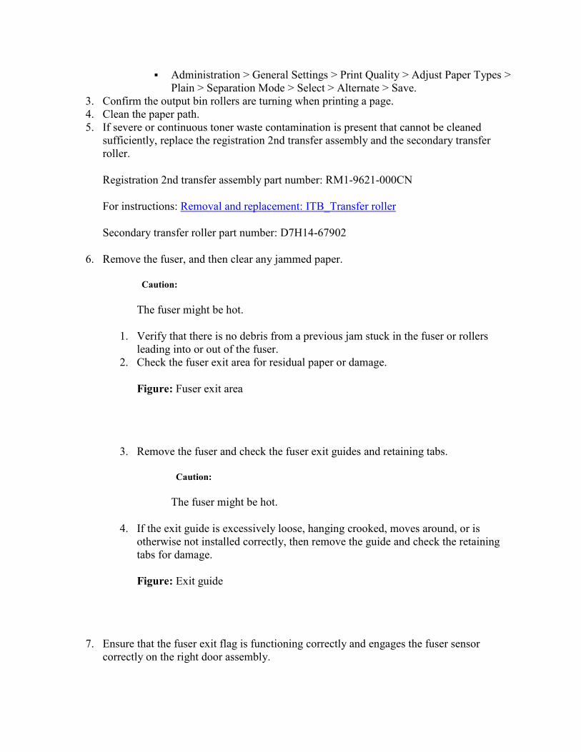
� Administration > General Settings > Print Quality > Adjust Paper Types >
Plain > Separation Mode > Select > Alternate > Save.
3. Confirm the output bin rollers are turning when printing a page.
4. Clean the paper path.
5. If severe or continuous toner waste contamination is present that cannot be cleaned
sufficiently, replace the registration 2nd transfer assembly and the secondary transfer
roller.
Registration 2nd transfer assembly part number: RM1-9621-000CN
For instructions: Removal and replacement: ITB_Transfer roller
Secondary transfer roller part number: D7H14-67902
6. Remove the fuser, and then clear any jammed paper.
Caution:
The fuser might be hot.
1. Verify that there is no debris from a previous jam stuck in the fuser or rollers
leading into or out of the fuser.
2. Check the fuser exit area for residual paper or damage.
Figure: Fuser exit area
3. Remove the fuser and check the fuser exit guides and retaining tabs.
Caution:
The fuser might be hot.
4. If the exit guide is excessively loose, hanging crooked, moves around, or is
otherwise not installed correctly, then remove the guide and check the retaining
tabs for damage.
Figure: Exit guide
7. Ensure that the fuser exit flag is functioning correctly and engages the fuser sensor
correctly on the right door assembly.

8. If the flag on the fuser is broken or damaged, check the event log for the 10.23.70 code
and replace the fuser.
o If a 10.23.70 error is listed, the supply is past very low. Inform the customer that
they must order and pay for the replacement.
o If an active low warning is not listed, replace the part under warranty.
For instructions: Removal and replacement: Fuser
Fuser (110V) part number: C1N54-67901
Fuser (220V) part number: C1N58-67901
9. note:
10. When an HP supply has reached the very low threshold, the HP Premium
Protection Warranty ends and the customer becomes responsible for the
replacement.
11. Test SR35 and verify that the sensor is functioning correctly.
0. Open the following menus:
� Administration
� Troubleshooting
� Diagnostic Tests
� Manual Sensor Test
1. Select SR35.
12. If the sensor test fails, replace the right door assembly.
Part number: RM2-0281-000CN
13. Remove the exit guide.
0. Use a flat-blade screw driver to lift up on the center of the exit guide to release the
holding pin (circle with arrow callout) and slide the guide gently to the right to
free the retaining tabs.
Figure: Remove the exit guide
1. With the exit guide removed, check the tabs on the guide. If any of these tabs are
broken, elevate the issue using the Standard Support Process.
Note:
This guide might be damaged due to a previous repair of parts around and
near the guide.
Figure: Exit guide tabs
2. If the tabs are not broken, reinstall the guide making sure that it is secured
correctly. Ensure that the four retaining tabs are inserted correctly into the sheet
metal.
Figure: Reinstall guide
Callout 1: Visible retaining tabs
Callout 2: Retaining tabs on the back side of the guide
14. If the jam error occurs only when duplexing, clean the right door rollers, sensors, and
actuators for the fuser exit. If everything already looks clean, replace the right-door sub
assembly.
Part number: RM1-9640-000CN
15. If the jam occurs on simplex and duplex jobs, open the IPTU and inspect it for damage
and debris.
16. With IPTU open, use the Component Test menu to test the motor (M202).
0. Open the following menus:
� Administration
� Troubleshooting
� Component Test
1. Select M202 and then watch for the rollers moving in the IPTU.
17. If M202 is not functioning and the rollers do not turn correctly, test IPTU motor M201. If
only M202 fails, replace the M202 stepping motor.
Part number: RK2-1320-000CN
18. Check all connectors on the controller for damage, correct seating, and secure
connection.
19. If both motors fail and the connectors are not damaged, replace the IPTU controller PCA.
Part number: RM2-7019-000CN
Figure: IPTU controller PCA
o 1 - J7003

o 2 - J7006
o 3 - J7008
o 4 - J7007
o 5 - J7004
o 6 - J7001
o 7 - J7005
20. If any of the connectors are damaged, replace the finisher lock assembly/ITPU.
Part number: RM2-5038-000CN
Figure: Lock assembly
21. If the error persists, check the event log for the 10.23.70 code and replace the fuser.
Note:
When an HP supply has reached the very low threshold, the HP Premium
Protection Warranty ends and the customer becomes responsible for the
replacement.
o If a 10.23.70 error is listed, the supply is past very low. Inform the customer that
they must order and pay for the replacement.
o If an active low warning is not listed, replace the part under warranty.
For instructions: Removal and replacement: Fuser
Fuser (110V) part number: C1N54-67901
Fuser (220V) part number: C1N58-67901
13. B9.Bz Jam in right door
This jam occurs when a near complete overlap (less than 5 to 15 mm of non-overlap) multi-feed
jam is detected at the fuser.
• 13. B9.B1 Multi-Feed jam is detected when printing from tray 1.
• 13. B9.B2 Multi-Feed jam is detected when printing from tray 2.
• 13. B9.B3 Multi-Feed jam is detected when printing from tray 3.
• 13. B9.B4 Multi-Feed jam is detected when printing from tray 4.
• 13. B9.B5 Multi-Feed jam is detected when printing from tray 5.
• 13. B9.BD Multi-Feed jam is detected when printing from the duplexer.
Recommended action
1. Open the right door and clear the jam in the indicated area.
2. Close the door to allow the printer to attempt to clear the jam.
3. If standard paper is being used, skip to the next step. If using light or recycled paper
when this error occurs, perform the following steps:
1. Use a better quality of paper (poor quality light or recycled paper has been shown
to cause this error).
2. Use a fresh ream of paper and Ensure that the paper has not been stored in a
humid or moist environment (moist paper has been shown to cause this jam).
3. Adjust the following settings on the control panel to help the printer transfer the
paper through the paper path:
� Administration > General Settings > Print Quality > Adjust Paper Types >
Plain > Print Mode > Select > Extra Light Mode > Save.
� Administration > General Settings > Print Quality > Adjust Paper Types >
Plain > Separation Mode > Select > Alternate > Save.
4. Clean the paper path.
5. If severe or continuous toner contamination is present that cannot be cleaned
sufficiently, replace the registration 2nd transfer assembly and the secondary
transfer roller.
Registration 2nd transfer assembly part number: RM1-9621-000CN
For instructions: Removal and replacement: ITB_Transfer roller
Secondary transfer roller part number: D7H14-67902
4. Ensure that the paper meets the HP specifications for the printer and is loaded correctly in
the trays.
5. Ensure that the pickup, feed, and separation rollers for the specified tray are installed
correctly.
6. Clean or replace the pickup and feed rollers as needed.
Tray 1 part number (pickup): A2W77-67906
Tray 2 part number (T2, pickup, feed): A2W77-67905
13. B9.Cz
Fuser wrap jam.
This jam occurs when the paper disappears from the fuser output sensor (SR35) before a
designated amount of time after the paper reached the fuser output sensor (SR35).
(It is determined that the paper is being wrapped around the fuser roller)
Z = Fuser mode
• 13. B9.C1 Fuser wrap jam when Auto Sense (Normal).
• 13. B9.C2 Fuser wrap jam when Normal.
• 13. B9.C3 Fuser wrap jam when Light 1 or Light 2.
• 13. B9.C4 Fuser wrap jam when Heavy 1.
• 13. B9.C5 Fuser wrap jam when Heavy 2.
• 13. B9.C6 Fuser wrap jam when Heavy paper 3.
• 13. B9.C7 Fuser wrap jam when Glossy paper 1.
• 13. B9.C8 Fuser wrap jam when Glossy paper 2.
• 13. B9.C9 Fuser wrap jam when Glossy paper 3.
• 13. B9.CB Fuser wrap jam when Transparency.
• 13. B9.CC Fuser wrap jam when Label.
• 13. B9.CD Fuser wrap jam when Envelope 1 or Envelope 2.
Recommended action
1. Open the right door and remove the fuser.
Caution:
The fuser might be hot.
2. Remove any paper wrapped around the fuser roller.
3. Reinstall the fuser, and then close the door.
4. Print a cleaning page to ensure that all of the toner is removed from the fuser roller.
5. If standard paper is being used, skip to the next step. If using light or recycled paper
when this error occurs, perform the following steps:
1. Use a better quality of paper (poor quality light or recycled paper has been shown
to cause this error).
2. Use a fresh ream of paper and Ensure that the paper has not been stored in a
humid or moist environment (moist paper has been shown to cause this jam).
3. Adjust the following settings on the control panel to help the printer transfer the
paper through the paper path:
� Administration > General Settings > Print Quality > Adjust Paper Types >
Plain > Print Mode > Select > Extra Light Mode > Save.
� Administration > General Settings > Print Quality > Adjust Paper Types >
Plain > Separation Mode > Select > Alternate > Save.
6. Clean the paper path.
7. If severe or continuous toner waste contamination is present that cannot be cleaned
sufficiently, replace the registration 2nd transfer assembly and the secondary transfer
roller.
Registration 2nd transfer assembly part number: RM1-9621-000CN
For instructions: Removal and replacement: ITB_Transfer roller
Secondary transfer roller part number: D7H14-67902
8. Ensure that the fuser exit flag is functioning correctly and engages the fuser sensor on the
right door assembly.
9. If the fuser exit flag is broken or damaged, check the event log for the 10.23.70 code and
replace the fuser.

o If a 10.23.70 error is listed, the supply is past very low. Inform the customer that
they must order and pay for the replacement.
o If an active low warning is not listed, replace the part under warranty.
For instructions: Removal and replacement: Fuser
Fuser (110V) part number: C1N54-67901
Fuser (220V) part number: C1N58-67901
10. note:
11. When an HP supply has reached the very low threshold, the HP Premium
Protection Warranty ends and the customer becomes responsible for the
replacement.
12. Test SR35 and verify that the fuser sensor on the right door is functioning correctly.
0. Open the following menus:
� Administration
� Troubleshooting
� Diagnostic Tests
� Manual Sensor Test
1. Select SR35.
13. If the test fails, replace the right door sub assembly.
Part number: RM1-9640-000CN
14. If the error persists, the fuser roller or pressure roller might be damaged. Check the event
log for a 10.23.70 code and replace the fuser.
o If a 10.23.70 error is listed, the supply is past very low. Inform the customer that
they must order and pay for the replacement.
o If an active low warning is not listed, replace the part under warranty.
For instructions: Removal and replacement: Fuser
Fuser (110V) part number: C1N54-67901
Fuser (220V) part number: C1N58-67901
15. note:
16. When an HP supply has reached the very low threshold, the HP Premium
Protection Warranty ends and the customer becomes responsible for the
replacement.
13. B9.Dz
Fuser delivery delay jam.
This jam occurs when the media does not reach the fuser output sensor (SR35) before a
designated amount of time after the registration sensor (SR2501) sensed the leading edge when
printing.

• 13. B9.D1 Fuser delivery delay jam when printing from tray 1.
• 13. B9.D2 Fuser delivery delay jam when printing from tray 2.
• 13. B9.D3 Fuser delivery delay jam when printing from tray 3.
• 13. B9.D4 Fuser delivery delay jam when printing from tray 4.
• 13. B9.D5 Fuser delivery delay jam when printing from tray 5.
• 13. B9.DD Fuser delivery delay jam when printing with the duplexer.
Preliminary Troubleshooting
1. Open the right door and clear the jam in the indicated area.
2. Close the door to allow the printer to attempt to clear the jam.
Paper stopped before the fuser
1. Thoroughly check the duplex paper path and the ITB/transfer area for issues with rollers,
jammed paper or any potential obstructions that might be causing the jam.
2. If standard paper is being used, skip to the next step. If using light or recycled paper
when this error occurs, perform the following steps:
1. Use a better quality of paper (poor quality light or recycled paper has been shown
to cause this error).
2. Use a fresh ream of paper and Ensure that the paper has not been stored in a
humid or moist environment (moist paper has been shown to cause this jam).
3. Adjust the following settings on the control panel to help the printer transfer the
paper through the paper path:
� Administration > General Settings > Print Quality > Adjust Paper Types >
Plain > Print Mode > Select > Extra Light Mode > Save.
� Administration > General Settings > Print Quality > Adjust Paper Types >
Plain > Separation Mode > Select > Alternate > Save.
4. Clean the paper path. If possible, vacuum the toner dust from the ITB area.
5. Run a cleaning page. Also, schedule regular cleaning pages to prevent these jams.
6. If severe or continuous toner waste contamination is present that cannot be
cleaned sufficiently, replace the 2nd transfer assembly.
Part number: RM1-9621-000CN
3. Verify that the transfer roller is seated correctly and not worn or deformed.
4. If damaged, check the event log for the 10.22.70 code and replace the transfer roller.
o If a 10.22.70 error is listed, the supply is past very low. Inform the customer that
they must order and pay for the replacement. HP recommends that the customer
order and install a maintenance kit at this time.
o If an active low warning is not listed, replace the part under warranty.
For instructions: Removal and replacement: ITB_Transfer roller
Part number: D7H14-67902

5. note:
6. When an HP supply has reached the very low threshold, the HP Premium
Protection Warranty ends and the customer becomes responsible for the
replacement.
7. Inspect the transfer feed assembly for debris or damage.
8. If damaged, or if the error persists, replace the right door sub assembly.
Part number: RM1-9640-000CN
Paper stopped in or at the fuser
1. Remove the fuser and inspect the fuser rollers for blockage and/or damage.
Caution:
The fuser might be hot.
2. Make sure the fuser exit flag is functioning correctly.
3. If the flag on the fuser is broken or damaged and does not engage the fuser sensor on the
right door assembly, or if the fuser is damaged, check the event log for the 10.23.70 code
and replace the fuser.
o If a 10.23.70 error is listed, the supply is past very low. Inform the customer that
they must order and pay for the replacement.
o If an active low warning is not listed, replace the part under warranty.
For instructions: Removal and replacement: Fuser
Fuser (110V) part number: C1N54-67901
Fuser (220V) part number: C1N58-67901
4. note:
5. When an HP supply has reached the very low threshold, the HP Premium
Protection Warranty ends and the customer becomes responsible for the
replacement.
6. Verify that fuser inlet guide is not detached or broken. Reinstall or reseat the guide as
needed.
7. Open the following menus:
o Administration
o Troubleshooting
o Diagnostic Tests
8. Test SR35 and verify that the fuser sensor is functioning correctly.
1. Open the following menus:
� Administration
� Troubleshooting
� Diagnostic Tests
� Manual Sensor Test

2. Select SR35.
9. If the sensor test fails, replace the right door assembly.
Part number: RM1-9640-000CN
10. Run the fuser motor drive test to verify that the fuser drive and gears are functioning
correctly. If they are not, replace the fuser motor assembly.
Part numbers: RM1-4519-000CN
13. B9.FF
Residual paper jam at the fuser output sensor.
This jam occurs when residual paper is detected at the fuser output sensor (SR35) at power on.
Recommended action
1. Open the right door and clear the jam in the indicated area.
2. Close the door to allow the printer to attempt to clear the jam.
3. If standard paper is being used, skip to the next step. If using light or recycled paper
when this error occurs, perform the following steps:
1. Use a better quality of paper (poor quality light or recycled paper has been shown
to cause this error).
2. Use a fresh ream of paper and Ensure that the paper has not been stored in a
humid or moist environment (moist paper has been shown to cause this jam).
3. Adjust the following settings on the control panel to help the printer transfer the
paper through the paper path.
� Administration > General Settings > Print Quality > Adjust Paper Types >
Plain > Print Mode > Select > Extra Light Mode > Save.
� Administration > General Settings > Print Quality > Adjust Paper Types >
Plain > Separation Mode > Select > Alternate > Save.
4. Clean the paper path.
5. If severe or continuous toner waste contamination is present that cannot be cleaned
sufficiently, replace the 2nd transfer assembly.
Registration 2nd transfer assembly part number: RM1-9621-000CN
For instructions: Removal and replacement: ITB_Transfer roller
Secondary transfer roller part number: D7H14-67902
6. Remove the fuser, and inspect the fuser rollers.
Caution:
The fuser might be hot.

7. Ensure that the fuser exit flag is functioning correctly, and engages the fuser sensor on
the right door assembly.
8. If the fuser rollers or the fuser exit flag is damaged, check the event log for the 10.23.70
code and replace the fuser.
Note:
After an HP supply has reached the very low threshold, the HP Premium
Protection Warranty ends and the customer becomes responsible for the
replacement.
o If a 10.23.70 error is listed, the supply is past very low. Inform the customer that
they must order and pay for the replacement.
o If an active low warning is not listed, replace the part under warranty.
For instructions: Removal and replacement: Fuser
Fuser (110V) part number: C1N54-67901
Fuser (220V) part number: C1N58-67901
9. If the error persists, test SR35 and verify that the fuser sensor on the right door is
functioning correctly.
0. Open the following menus:
� Administration
� Troubleshooting
� Diagnostic Tests
� Manual Sensor Test
1. Select SR35.
10. If the test fails, replace the right door sub assembly.
Part number: RM1-9640-000CN
11. If the error persists, run the fuser motor drive test to verify that the fuser drive and gears
are functioning correctly.
12. If the test fails, replace the fuser motor assembly.
Part number: RM1-4519-000CN
13. BA.EE
This jam occurs when the engine front door is opened during printing (sensor SW14).
Recommended action
1. Close the front door.
2. Check the projection tabs of the front door that engage the door sensors (SW14). If
damaged, replace the front door assembly.

Part number: A2W77-67907
3. Use the manual sensor test to activate the door switch.
1. Open the following menus:
� Administration
� Troubleshooting
� Diagnostic Tests
� Tray/Bin Manual Sensor Test
4. If the test fails, check the connectors on the DC controller PCA to ensure that they are
seated correctly and not damaged.
5. If the error persists, replace the switch.
Part number: RM2-7035-000CN
13. BB.EE
This jam occurs when the engine right door (SW13) is opened during printing.
Recommended action
1. Close the right door.
2. Check the projection tabs of the right door that engage the door sensor (SW13). If
damaged, replace the right door assembly.
Part number: RM1-9640-000CN
3. Use the manual sensor test to activate the door switch.
1. Open the following menus:
� Administration
� Troubleshooting
� Diagnostic Tests
� Tray/Bin Manual Sensor Test
4. If the test fails, replace the switch.
Part number: RM2-7035-000CN
5. If the error persists, check the connectors on the DC controller PCA to ensure that they
are seated correctly and not damaged.
13. D1.Az
Jam in the right door.
This jam occurs when the paper stays at the duplex switchback sensor (SR301) for a designated
amount of time after it has reached the SR301 sensor.
Z = Fuser Mode
• 13. D1.A1 The fuser is printing in fuser mode Auto Sense (Normal).
• 13. D1.A2 The fuser is printing in fuser mode Normal.
• 13. D1.A3 The fuser is printing in fuser mode Light 1 or Light 2.

• 13. D1.A4 The fuser is printing in fuser mode Heavy 1.
• 13. D1.A5 The fuser is printing in fuser mode Heavy 2.
• 13. D1.A6 The fuser is printing in fuser mode Heavy paper 3.
• 13. D1.A7 The fuser is printing in fuser mode Glossy paper 1.
• 13. D1.A8 The fuser is printing in fuser mode Glossy paper 2.
• 13. D1.A9 The fuser is printing in fuser mode Glossy paper 3.
• 13. D1.AB The fuser is printing in fuser mode Transparency.
• 13. D1.AC The fuser is printing in fuser mode Label.
Recommended action
1. Follow the on screen instructions to locate and remove the paper or obstruction.
2. Ensure that the type and quality of the paper that is being used meets the HP
specifications for the printer.
3. Turn the printer off.
4. Remove and reinstall the fuser.
Caution:
The fuser might be hot.
5. Test the duplexer reverse motor.
1. Open the following menus:
� Administration
� Troubleshooting
� Component Test
2. Select Duplexer reverse motor test. The duplexing reverse-motor test activates the
duplexing reverse motor for 10 seconds.
6. Test the duplexer refeed motor.
1. Open the following menus:
� Administration
� Troubleshooting
� Component Test
2. Select Duplexer refeed motor test. The duplexing refeed motor test activates the
duplexing refeed motor for 10 seconds.
7. If either of these tests fail, check the connectors (J1902, J9946, J1909, and J1908) for
correct seating and secure connection.
8. If the error persists and the connectors are not damaged, replace the duplex reverse
assembly.
M855 part number: RM2-0291-000CN
M880 part number: RM2-5061-000CN
9. If the motor tests pass, test SR301 (the duplex switchback sensor).
1. Open the following menus:
� Administration

� Troubleshooting
� Diagnostic Tests
� Manual Sensor Test
2. Select SR301, and then manually move the sensor to ensure that it moves freely
and responds correctly to the sensor test.
3. If the sensor test fails, check that the sensor flag moves freely.
4. Clean the area and then test again.
10. If the sensor test continues to fail, the sensor might be defective. Replace the duplex
reverse assembly.
M855 Part number: RM2-0291-000CN
M880 Part number: RM1-5061-000CN
11. If the sensor is functioning correctly, replace the right door assembly.
Part number: RM1-9640-000CN
13. D1.Dz
Jam in the right door.
The paper did not reach the duplex switchback sensor (SR301) in the designated amount of time
after the fuser output sensor (SR45) sensed the leading edge.
Z = Fuser Mode
• 13. D1.D1The fuser is printing in fuser mode Auto Sense.
• 13. D1.D2 The fuser is printing in fuser mode Normal.
• 13. D1.D3 The fuser is printing in fuser mode Light 1 or Light 2.
• 13. D1.D4 The fuser is printing in fuser mode Heavy 1.
• 13. D1.D5 The fuser is printing in fuser mode Heavy 2.
• 13. D1.D6 The fuser is printing in fuser mode Heavy paper 3.
• 13. D1.D7 The fuser is printing in fuser mode Glossy paper 1.
• 13. D1.D8 The fuser is printing in fuser mode Glossy paper 2.
• 13. D1.D9 The fuser is printing in fuser mode Glossy paper 3.
• 13. D1.DB The fuser is printing in fuser mode Transparency.
• 13. D1.DC The fuser is printing in fuser mode Label.
Preliminary Troubleshooting
1. Follow the on screen instructions to locate and remove the paper or obstruction.
2. Ensure that the type and quality of the paper that is being used meets the HP
specifications for the printer.
3. Determine where the leading and trailing edge of the paper is during the error state.
o Is it stopped in the fuser?
o Is it stopped in the diverter assembly?
o Is it stopped at the input of duplexer?

Stopped in the fuser
1. Remove the fuser and inspect the fuser and the rollers for blockage and/or damage.
Caution:
The fuser might be hot.
2. Check the fuser guide assembly and verify that is not causing the paper to get damaged
and be stuck at the fuser exit.
3. If the error persists, check the event log for the 10.23.70 code and replace the fuser.
Note:
When an HP supply has reached the very low threshold, the HP Premium
Protection Warranty ends and the customer becomes responsible for the
replacement.
o If a 10.23.70 error is listed, the supply is past very low. Inform the customer that
they must order and pay for the replacement.
o If an active low warning is not listed, replace the part under warranty.
For instructions: Removal and replacement: Fuser
Fuser (110V) part number: C1N54-67901
Fuser (220V) part number: C1N58-67901
Stopped in the diverter assembly
1. Check the right door assembly for blockage or damage.
2. Test SR301 to verify that the duplex switchback sensor is functioning correctly.
1. Open the following menus:
� Administration
� Troubleshooting
� Diagnostic Tests
� Manual Sensor Test
2. Select SR301, and then manually move the sensor to ensure that it moves freely
and responds correctly to the sensor test.
3. If the sensor test fails, check that the sensor flag moves freely.
4. Clean the area and test again.
3. If the sensor test continues to fail, the sensor might be defective. Replace the duplex
reverse assembly.
M855 part number: RM2-0291-000CN
M880 part number: RM1-5061-000CN

Stopped at the input of duplexer
1. Check that the duplex reverse motor and the refeed motor are functioning correctly.
2. Test the duplexer reverse motor.
1. Open the following menus:
� Administration
� Troubleshooting
� Component Test
2. Select Duplexer reverse motor test. The duplexing reverse-motor test activates the
duplexing reverse motor for 10 seconds.
3. Test the duplexer refeed motor.
1. Open the following menus:
� Administration
� Troubleshooting
� Component Test
2. Select Duplexer refeed motor test. The duplexing refeed motor test activates the
duplexing refeed motor for 10 seconds.
4. Check the connectors (J1902, J9946, J1909, and J1908) for correct seating and secure
connection.
5. If either of these tests fail and the connectors are not damaged, replace the duplex reverse
assembly.
M855 part number: RM2-0291-000CN
M880 part number: RM2-5061-000CN
6. Test SR301 to verify that the duplex switchback sensor is functioning correctly.
1. Open the following menus:
� Administration
� Troubleshooting
� Diagnostic Tests
� Manual Sensor Test
2. Select SR301, and then manually move the sensor to ensure that it moves freely
and responds correctly to the sensor test.
7. If the sensor fails to change state, ensure that the sensor flag moves freely, clean the area,
and then test again.
8. If the sensor test continues to fail, the sensor might be defective. Replace the duplex
reverse assembly.
M855 Part number: RM2-0291-000CN
M880 Part number: RM1-5061-000CN
9. If the sensor is functioning correctly, replace the right door assembly.
Part number: RM1-9640-000CN

13. D1.FF
Jam in the right door.
This jam occurs when residual paper is detected at the duplex switchback sensor (SR301) at
power on.
Recommended action
1. Open the right door and clear the jam in the indicated area.
2. Close the door to allow the printer to attempt to clear the jam.
3. Replace the duplex switchback assembly.
M855 part number: RM2-0291-000CN
M880 part number: RM2-5061-000CN
13. D3.Az
Jam in the right door.
This jam occurs when the paper stays at the duplex feed sensor (SR304) for the designated
amount of time after it has reached the SR304 sensor.
• 13. D3.A1 The fuser is printing in fuser mode Auto Sense.
• 13. D3.A2 The fuser is printing in fuser mode Normal.
• 13. D3.A3 The fuser is printing in fuser mode Light 1 or Light 2.
• 13. D3.A4 The fuser is printing in fuser mode Heavy 1.
• 13. D3.A5 The fuser is printing in fuser mode Heavy 2.
• 13. D3.A6 The fuser is printing in fuser mode Heavy paper 3.
• 13. D3.A7 The fuser is printing in fuser mode Glossy paper 1.
• 13. D3.A8 The fuser is printing in fuser mode Glossy paper 2.
• 13. D3.A9 The fuser is printing in fuser mode Glossy paper 3.
Recommended action
1. Follow the on screen instructions to locate and remove the paper or obstruction.
2. Ensure that the type and quality of the paper that is being used meets the HP
specifications for the printer.
3. Use the Component Test menu to perform the following motor tests:
1. Open the following menus:
� Administration
� Troubleshooting
� Component Test
2. Select the Duplexer reverse motor test. The duplexing reverse-motor test activates
the duplexing reverse motor for 10 seconds.
3. Select Duplexer refeed motor test. The duplexing refeed motor test activates the
duplexing refeed motor for 10 seconds.
4. Check the connectors (J1902, J9946, J1909, and J1908) for correct seating and secure
connection.

5. If either of motor tests fail and the connectors are not damaged, replace the duplex
reverse assembly.
M855 part number: RM2-0291-000CN
M880 part number: RM2-5061-000CN
6. If the motor tests pass, test SR304 to ensure that the duplex re-pick feed sensor is
functioning correctly.
1. Open the following menus:
� Administration
� Troubleshooting
� Diagnostic Tests
� Manual Sensor Test
2. Select SR304 and then manually move the sensor to ensure that it moves freely
and responds correctly to the sensor test.
3. If the sensor test fails, clean the sensor and then test again.
7. If the sensor test continues to fail, the sensor might be defective. Replace the duplex feed
assembly.
M855 Part number: A2W77-67913
M880 Part number: A2W75-67911
8. If the sensor is functioning correctly and the error persists, replace the right door
assembly.
Part number: RM1-9640-000CN
13. D3.Dz
Jam in the right door.
The paper did not reach the duplex refeed sensor (SR304) in the designated amount of time after
the duplex switchback sensor (SR302) sensed the leading edge:
• 13. D3.D1 The fuser is printing in fuser mode Auto Sense.
• 13. D3.D2 The fuser is printing in fuser mode Normal.
• 13. D3.D3 The fuser is printing in fuser mode Light 1 or Light 2.
• 13. D3.D4 The fuser is printing in fuser mode Heavy 1.
• 13. D3.D5 The fuser is printing in fuser mode Heavy 2.
• 13. D3.D6 The fuser is printing in fuser mode Heavy paper 3.
• 13. D3.D7 The fuser is printing in fuser mode Glossy paper 1.
• 13. D3.D8 The fuser is printing in fuser mode Glossy paper 2.
• 13. D3.D9 The fuser is printing in fuser mode Glossy paper 3.
Recommended action

1. Open the right door and clear the jam in the indicated area.
2. Close the door to allow the printer to attempt to clear the jam.
3. Use the Component Test menu to perform the following motor tests:
1. Open the following menus:
� Administration
� Troubleshooting
� Component Test
2. Select the Duplexer reverse motor test. The duplexing reverse-motor test activates
the duplexing reverse motor for 10 seconds.
3. Select Duplexer refeed motor test. The duplexing refeed motor test activates the
duplexing refeed motor for 10 seconds.
4. Check the connectors (J1902, J9946, J1909, and J1908) for correct seating and secure
connection.
5. If either of these tests fail and the connectors are not damaged, replace the duplex reverse
assembly.
M855 part number: RM2-0291-000CN
M880 part number: RM2-5061-000CN
6. If the motor tests pass, test SR304 to verify that the duplex re-pick feed sensor is
functioning correctly.
1. Open the following menus:
� Administration
� Troubleshooting
� Diagnostic Tests
� Manual Sensor Test
2. Select SR304, and then manually move the sensor to ensure that it moves freely
and responds correctly to the sensor test.
3. If the sensor test fails, clean the sensor and then test again.
7. If the sensor test continues to fail, the sensor might be defective. Replace the duplex feed
assembly.
M855 Part number: A2W77-67913
M880 Part number: A2W75-67911
8. If the sensor is functioning correctly and the error persists, replace the right door
assembly.
Part number: RM1-9640-000CN
13. D3.FF
Jam in the right door.
Residual paper is detected at the duplex delivery sensor (SR302) or the duplexer refeed sensor
(SR304) at power on.

Recommended action
1. Open the right door and clear the jam in the indicated area.
2. Close the door to allow the printer to attempt to clear the jam.
3. Use the Component Test menu to perform the following motor tests:
1. Open the following menus:
� Administration
� Troubleshooting
� Component Test
2. Select the Duplexer reverse motor test. The duplexing reverse-motor test activates
the duplexing reverse motor for 10 seconds.
3. Select Duplexer refeed motor test. The duplexing refeed motor test activates the
duplexing refeed motor for 10 seconds.
4. Check the connectors (J1902, J9946, J1909, and J1908) for correct seating and secure
connection.
5. If either of these tests fail and the connectors are not damaged, replace the duplex reverse
assembly.
M855 part number: RM2-0291-000CN
M880 part number: RM2-5061-000CN
6. If the motor tests pass, test SR304 and verify that the duplex re-pick feed sensor is
functioning correctly.
1. Open the following menus:
� Administration
� Troubleshooting
� Diagnostic Tests
� Manual Sensor Test
2. Select SR304, and then manually move the sensor to ensure that it moves freely
and responds correctly to the sensor test.
7. If the sensor fails, clean the sensor and then test again.
8. If the sensor test continues to fail, the sensor might be defective. Replace the duplex feed
assembly.
M855 Part number: A2W77-67913
M880 Part number: A2W75-67911
9. If the sensor is functioning correctly and the error persists, replace the right door
assembly.
Part number: RM1-9640-000CN
13. DF.Dz
Jam in the right door.

The paper did not reach either the duplex switchback sensor (SR301) or the duplex delivery
sensor (SR302) in a designated amount of time.
• 13. DF.D1 The fuser is printing in fuser mode Auto Sense.
• 13. DF.D2 The fuser is printing in fuser mode Normal.
• 13. DF.D3 The fuser is printing in fuser mode Light 1 or Light 2.
• 13. DF.D4 The fuser is printing in fuser mode Heavy 1.
• 13. DF.D5 The fuser is printing in fuser mode Heavy 2.
• 13. DF.D6 The fuser is printing in fuser mode Heavy paper 3.
• 13. DF.D7 The fuser is printing in fuser mode Glossy paper 1.
• 13. DF.D8 The fuser is printing in fuser mode Glossy paper 2.
• 13. DF.D9 The fuser is printing in fuser mode Glossy paper 3.
Recommended action
1. Open the right door and clear the jam in the indicated area.
2. Close the door to allow the printer to attempt to clear the jam.
3. Ensure that the type and quality of the paper that is being used meets the HP
specifications for the printer.
1. Open the following menus:
� Administration
� Troubleshooting
� Component Test
4. Use the Component Test menu to test the duplex reverse and refeed motors and verify
that they are functioning correctly.
5. Use the Component Test menu to test the duplexer motors:
1. Open the following menus:
� Administration
� Troubleshooting
� Component Test
2. Select the Duplexer reverse motor test. The duplexing reverse-motor test activates
the duplexing reverse motor for 10 seconds.
3. Select the Duplexer refeed motor test. The duplexing refeed motor test activates
the duplexing refeed motor for 10 seconds.
6. If the test fails, check the connectors (J1902, J9946, J1909, and J1908) for correct seating
and secure connection.
7. If either of these tests fail and the connectors are not damaged, replace the duplex reverse
assembly.
M855 part number: RM2-0291-000CN
M880 part number: RM2-5061-000CN
8. If the motor tests pass, test the duplex sensors and verify that they are functioning
correctly.
1. Open the following menus:

� Administration
� Troubleshooting
� Diagnostic Tests
� Manual Sensor Test
2. Test all of the following sensors:
� SR301 Duplex switchback sensor
� SR302 Duplex feed sensor
� SR304 Duplex refeed sensor
9. If a sensor test fails, ensure that the sensor moves freely, clean the sensor, and then test
again.
10. If the sensor test continues to fail, the sensor might be defective. Replace the duplex feed
assembly.
M855 part number: A2W77-67913
M880 part number: A2W75-67911
11. If the sensor is functioning correctly and the error persists, replace the right door
assembly.
Part number: RM1-9640-000CN
13. E1.Dz
Jam in the right door.
The paper did not reach the face down sensor (SR33) in the designated amount of time after the
fuser delivery sensor 2 (SR45) sensed the leading edge.
• 13. E1.D1 The fuser is printing in fuser mode Auto Sense.
• 13. E1.D2 The fuser is printing in fuser mode Normal.
• 13. E1.D3 The fuser is printing in fuser mode Light 1 or Light 2.
• 13. E1.D4 The fuser is printing in fuser mode Heavy 1.
• 13. E1.D5 The fuser is printing in fuser mode Heavy 2.
• 13. E1.D6 The fuser is printing in fuser mode Heavy paper 3.
• 13. E1.D7 The fuser is printing in fuser mode Glossy paper 1.
• 13. E1.D8 The fuser is printing in fuser mode Glossy paper 2.
• 13. E1.D9 The fuser is printing in fuser mode Glossy paper 3.
• 13. E1.DB The fuser is printing in fuser mode Transparency.
• 13. E1.DC The fuser is printing in fuser mode Label.
• 13. E1.DD The fuser is printing in fuser mode Envelope 1, 2, 3.
• 13. E1.DE The fuser is printing in fuser mode Rough media.
• 13. E1.D0 The fuser is printing in fuser mode Photo Media.
Recommended action
1. Open the right door and clear the jam in the indicated area.
2. Close the door to allow the printer to attempt to clear the jam.

3. Ensure that the delivery sensor flag moves smoothly.
4. Test SR33 and verify that the face-down bin full sensor is functioning correctly.
1. Open the following menus:
� Administration
� Troubleshooting
� Diagnostic Tests
� Manual Sensor Test
2. Select SR33.
5. If the test fails, replace the delivery sensor assembly.
Part number: RM1-9841-000CN
6. If the test passes, make sure the fuser is installed correctly, and inspect the fuser guide
and the fuser for damage or wear.
7. If damaged, check the event log for the 10.23.70 code and replace the fuser.
Note:
When an HP supply has reached the very low threshold, the HP Premium
Protection Warranty ends and the customer becomes responsible for the
replacement.
o If a 10.23.70 error is listed, the supply is past very low. Inform the customer that
they must order and pay for the replacement.
o If an active low warning is not listed, replace the part under warranty.
For instructions: Removal and replacement: Fuser
Fuser (110V) part number: C1N54-67901
Fuser (220V) part number: C1N58-67901
8. If the error persists, inspect the right door sub assembly and replace if damaged.
Part number: RM1-9640-000CN
9. If the error persists, replace the face-down delivery assembly.
Part number: RM2-6868-000CN
13. E1.FF
Jam in the right door.
This jam occurs when residual paper is detected at the face down bin full sensor (SR33) at power
on.
Recommended action
1. Remove the paper from the top output bin.
2. Open the right door and clear the jam in the indicated area.
3. Close the door to allow the printer to attempt to clear the jam.
4. Ensure that the delivery sensor flag moves smoothly.
5. Test SR33 and verify that the face-down bin full sensor is functioning correctly.
1. Open the following menus:
� Administration
� Troubleshooting
� Diagnostic Tests
� Manual Sensor Test
2. Select SR33.
6. If the test fails, replace the delivery sensor assembly.
Part number: RM1-9841-000CN
7. If the test passes, make sure the fuser is installed correctly, and inspect the fuser guide
and the fuser for damage or wear.
8. If damaged, check the event log for the 10.23.70 code and replace the fuser.
Note:
When an HP supply has reached the very low threshold, the HP Premium
Protection Warranty ends and the customer becomes responsible for the
replacement.
o If a 10.23.70 error is listed, the supply is past very low. Inform the customer that
they must order and pay for the replacement.
o If an active low warning is not listed, replace the part under warranty.
For instructions: Removal and replacement: Fuser
Fuser (110V) part number: C1N54-67901
Fuser (220V) part number: C1N58-67901
9. If the error persists, replace the face-down delivery assembly.
Part number: RM2-6868-000CN
13. E2.Az
Stay jam in the input area of the IPTU.
This jam occurs when the paper stays at the IPTU feed sensor 1 (SR203) for a designated time
period after the sensor detects the paper.
• 13. E2.A1 The fuser is printing in fuser mode Auto Sense.
• 13. E2.A2 The fuser is printing in fuser mode Normal.

• 13.E2.A3 The fuser is printing in fuser mode Light 1 or Light 2
• 13. E2.A4 The fuser is printing in fuser mode Heavy 1.
• 13. E2.A5 The fuser is printing in fuser mode Heavy 2.
• 13. E2.A6 The fuser is printing in fuser mode Heavy paper 3.
• 13. E2.A7 The fuser is printing in fuser mode Glossy paper 1.
• 13. E2.A8 The fuser is printing in fuser mode Glossy paper 2.
• 13. E2.A9 The fuser is printing in fuser mode Glossy paper 3.
• 13. E2.AB The fuser is printing in fuser mode Transparency.
• 13. E2.AC The fuser is printing in fuser mode Label.
• 13.E2.AD The fuser is printing in fuser mode Envelope 1 or Envelope 2
Recommended action
1. Follow the on screen instructions to locate and remove the paper or obstruction.
2. Ensure that the type and quality of the paper that is being used meets the HP
specifications for the printer.
3. Check the input side of the IPTU for any damaged or excessive wear.
4. Ensure that the delivery assembly is not damaged and the finisher is aligned correctly
with the printer.
5. Open the IPTU cover and run the IPTU drive motor test to ensure that the paper-transport
motors are functioning correctly.
6. Test the IPTU drive motor.
1. Open the following menus:
� Administration
� Troubleshooting
� Diagnostic Tests
� Component Test
2. Select the IPTU drive motor test.
Note:
This test activates the IPTU motors and is only available when the IPTU is
installed. During the test, observe the two sets of rollers on the right side
and left side while facing the IPTU. M201 drives the input area rollers of
the IPTU and M202 drives the output area rollers.
7. If the rollers in one area of the IPTU do not rotate, replace the DC motor assembly M201
or M202.
Part number: RK2-1320-000CN
8. If both sets of rollers react the same way, rotate or do not rotate, check the IPTU around
sensor SR203 for something blocking the paper path or for any damage or excessive
wear.
9. Test the SR201, SR202, and SR203 paper path sensors in the IPTU.
1. Open the following menus:
� Administration

� Troubleshooting
� Diagnostic Tests
� Manual Sensor Test
2. Test all three IPTU paper path sensors, SR201, SR202, and SR203.
3. If the IPTU drive motor test passed, and the sensor test fails, replace the IPTU
lower guide assembly.
Part number: RM2-5057-000CN
4. If the IPTU drive motor test failed, and the sensor test fails replace the IPTU
controller PCA.
Part number: RM2-7019-000CN
10. If the error persists, replace the IPTU lower guide assembly.
Part number: RM2-5057-000CN
13. E2.Dz
Delay jam at the input area of the IPTU.
The paper did not reach the IPTU feed sensor 1 (SR203) in the designated amount of time.
• 13. E2.D1 The fuser is printing in fuser mode Auto Sense.
• 13. E2.D2 The fuser is printing in fuser mode Normal.
• 13. E2.D3 The fuser is printing in fuser mode Light 1 or Light 2.
• 13. E2.D4 The fuser is printing in fuser mode Heavy 1.
• 13. E2.D5 The fuser is printing in fuser mode Heavy 2.
• 13. E2.D6 The fuser is printing in fuser mode Heavy paper 3.
• 13. E2.D7 The fuser is printing in fuser mode Glossy paper 1.
• 13. E2.D8 The fuser is printing in fuser mode Glossy paper 2.
• 13. E2.D9 The fuser is printing in fuser mode Glossy paper 3.
• 13. E2.DB The fuser is printing in fuser mode Transparency.
• 13. E2.DC The fuser is printing in fuser mode Label.
• 13. E2.DD The fuser is printing in fuser mode Envelope 1 or Envelope 2.
Recommended action
1. Follow the on screen instructions to locate and remove the paper or obstruction.
2. Ensure that the type and quality of the paper that is being used meets the HP
specifications for the printer.
3. Check the input side of the IPTU for any damaged or excessive wear.
4. Ensure that the delivery assembly is not damaged and the finisher is aligned correctly
with the printer.
5. Open the IPTU cover and run the IPTU drive motor test to ensure that the paper-transport
motors are functioning correctly.
6. Test the IPTU drive motor.
1. Open the following menus:
� Administration
� Troubleshooting
� Diagnostic Tests
� Component Test
2. Select the IPTU drive motor test.
Note:
This test activates the IPTU motors and is only available when the IPTU is
installed. During the test, observe the two sets of rollers on the right side
and left side while facing the IPTU. M201 drives the input area rollers of
the IPTU and M202 drives the output area rollers.
7. If the rollers in one area of the IPTU do not rotate, replace the DC motor assembly M201
or M202.
Part number: RK2-1320-000CN
If both sets of rollers react the same way, rotate or do not rotate, proceed with the next
step.
8. Check the IPTU around sensor SR203 to see if there is something possibly blocking the
paper path or for any damaged or excessive wear.
9. Test the SR201, SR202, and SR203 paper path sensors in the IPTU.
1. Open the following menus:
� Administration
� Troubleshooting
� Diagnostic Tests
� Manual Sensor Test
2. Test all three IPTU paper path sensors, SR201, SR202, and SR203.
3. If the IPTU drive motor test passed, and the sensor test fails replace the IPTU
lower guide assembly.
Part number: RM2-5057-000CN
4. If the IPTU drive motor test failed, and the sensor test fails replace the IPTU
controller PCA.
Part number: RM2-7019-000CN
10. If the error persists, replace the IPTU lower guide assembly.
Part number: RM2-5057-000CN
13. E3.Az
Stay jam in the IPTU.
This jam occurs when the paper stays at the IPTU feed sensor 2 (SR202) for a designated time
period after the sensor detects the paper.
• 13. E3.A1 The fuser is printing in fuser mode Auto Sense.
• 13. E3.A2 The fuser is printing in fuser mode Normal.
• 13. E3.A3 The fuser is printing in fuser mode Light 1 or Light 2.
• 13. E3.A4 The fuser is printing in fuser mode Heavy 1.
• 13. E3.A5 The fuser is printing in fuser mode Heavy 2.
• 13. E3.A6 The fuser is printing in fuser mode Heavy paper 3.
• 13. E3.A7 The fuser is printing in fuser mode Glossy paper 1.
• 13. E3.A8 The fuser is printing in fuser mode Glossy paper 2.
• 13. E3.A9 The fuser is printing in fuser mode Glossy paper 3.
• 13. E3.AB The fuser is printing in fuser mode Transparency.
• 13. E3.AC The fuser is printing in fuser mode Label.
• 13. E3.AD The fuser is printing in fuser mode Envelope 1 or Envelope 2.
Recommended action
1. Follow the on screen instructions to locate and remove the paper or obstruction.
2. Ensure that the type and quality of the paper that is being used meets the HP
specifications for the printer.
3. Check the input side of the IPTU for any damaged or excessive wear.
4. Ensure that the delivery assembly is not damaged and the finisher is aligned correctly
with the printer.
5. Open the IPTU cover and run the IPTU drive motor test to ensure that the paper-transport
motors are functioning correctly.
6. Test the IPTU drive motor.
1. Open the following menus:
� Administration
� Troubleshooting
� Diagnostic Tests
� Component Test
2. Select the IPTU drive motor test.
Note:
This test activates the IPTU motors and is only available when the IPTU is
installed. During the test, observe the two sets of rollers on the right side
and left side while facing the IPTU. M201 drives the input area rollers of
the IPTU and M202 drives the output area rollers.
7. If the rollers in one area of the IPTU do not rotate, replace the DC motor assembly M201
or M202.
Part number: RK2-1320-000CN

8. If both sets of rollers react the same way, rotate or do not rotate, check the IPTU around
sensor SR203 for something blocking the paper path or for any damage or excessive
wear.
9. Test the SR201, SR202, and SR203 paper path sensors in the IPTU.
1. Open the following menus:
� Administration
� Troubleshooting
� Diagnostic Tests
� Manual Sensor Test
2. Test all three IPTU paper path sensors, SR201, SR202, and SR203.
3. If the IPTU drive motor test passed, and the sensor test fails replace the IPTU
lower guide assembly.
Part number: RM2-5057-000CN
4. If the IPTU drive motor test failed, and the sensor test fails replace the IPTU
controller PCA.
Part number: RM2-7019-000CN
10. If the error persists, replace the IPTU lower guide assembly.
Part number: RM2-5057-000CN
13. E3.Dz
Delay jam in the IPTU.
The paper did not reach the IPTU feed sensor 2 (SR202) in the designated amount of time.
• 13. E3.D1 The fuser is printing in fuser mode Auto Sense.
• 13. E3.D2 The fuser is printing in fuser mode Normal.
• 13. E3.D3 The fuser is printing in fuser mode Light 1 or Light 2.
• 13. E3.D4 The fuser is printing in fuser mode Heavy 1.
• 13. E3.D5 The fuser is printing in fuser mode Heavy 2.
• 13. E3.D6 The fuser is printing in fuser mode Heavy paper 3.
• 13. E3.D7 The fuser is printing in fuser mode Glossy paper 1.
• 13. E3.D8 The fuser is printing in fuser mode Glossy paper 2.
• 13. E3.D9 The fuser is printing in fuser mode Glossy paper 3.
• 13. E3.DB The fuser is printing in fuser mode Transparency.
• 13. E3.DC The fuser is printing in fuser mode Label.
• 13.E3.DD The fuser is printing in fuser mode Envelope 1 or Envelope 2
Recommended action
1. Follow the on screen instructions to locate and remove the paper or obstruction.
2. Ensure that the type and quality of the paper that is being used meets the HP
specifications for the printer.

3. Check the input side of the IPTU for any damaged or excessive wear.
4. Ensure that the delivery assembly is not damaged and the finisher is aligned correctly
with the printer.
5. Open the IPTU cover and run the IPTU drive motor test to ensure that the paper-transport
motors are functioning correctly.
6. Test the IPTU drive motor.
1. Open the following menus:
� Administration
� Troubleshooting
� Diagnostic Tests
� Component Test
2. Select the IPTU drive motor test.
Note:
This test activates the IPTU motors and is only available when the IPTU is
installed. During the test, observe the two sets of rollers on the right side
and left side while facing the IPTU. M201 drives the input area rollers of
the IPTU and M202 drives the output area rollers.
7. If the rollers in one area of the IPTU do not rotate, replace the DC motor assembly M201
or M202.
Part number: RK2-1320-000CN
8. If both sets of rollers react the same way, rotate or do not rotate, check the IPTU around
sensor SR203 for something blocking the paper path or for any damage or excessive
wear.
9. Test the SR201, SR202, and SR203 paper path sensors in the IPTU.
1. Open the following menus:
� Administration
� Troubleshooting
� Diagnostic Tests
� Manual Sensor Test
2. Test all three IPTU paper path sensors, SR201, SR202, and SR203.
3. If the IPTU drive motor test passed, and the sensor test fails replace the IPTU
lower guide assembly.
Part number: RM2-5057-000CN
4. If the IPTU drive motor test failed, and the sensor test fails replace the IPTU
controller PCA.
Part number: RM2-7019-000CN
10. If the error persists, replace the IPTU lower guide assembly.

Part number: RM2-5057-000CN
13. E4.Az
Stay jam at the exit area of the IPTU.
This jam occurs when the paper stays at the IPTU feed sensor 3 (SR201) for a designated time
period after the sensor detects the paper.
• 13. E4.A1 The fuser is printing in fuser mode Auto Sense.
• 13. E4.A2 The fuser is printing in fuser mode Normal.
• 13. E4.A3 The fuser is printing in fuser mode Light 1 or Light 2.
• 13. E4.A4 The fuser is printing in fuser mode Heavy 1.
• 13. E4.A5 The fuser is printing in fuser mode Heavy 2.
• 13. E4.A6 The fuser is printing in fuser mode Heavy paper 3.
• 13. E4.A7 The fuser is printing in fuser mode Glossy paper 1.
• 13. E4.A8 The fuser is printing in fuser mode Glossy paper 2.
• 13. E4.A9 The fuser is printing in fuser mode Glossy paper 3.
• 13. E4.AB The fuser is printing in fuser mode Transparency.
• 13. E4.AC The fuser is printing in fuser mode Label.
• 13. E4.AD The fuser is printing in fuser mode Envelope 1 or Envelope 2.
Recommended action
1. Follow the on screen instructions to locate and remove the paper or obstruction.
2. Ensure that the type and quality of the paper that is being used meets the HP
specifications for the printer.
3. Check the input side of the IPTU for any damaged or excessive wear.
4. Ensure that the delivery assembly is not damaged and the finisher is aligned correctly
with the printer.
5. Open the IPTU cover and run the IPTU drive motor test to ensure that the paper-transport
motors are functioning correctly.
6. Test the IPTU drive motor.
1. Open the following menus:
� Administration
� Troubleshooting
� Diagnostic Tests
� Component Test
2. Select the IPTU drive motor test.
Note:
This test activates the IPTU motors and is only available when the IPTU is
installed. During the test, observe the two sets of rollers on the right side
and left side while facing the IPTU. M201 drives the input area rollers of
the IPTU and M202 drives the output area rollers.
3. If the rollers in one area of the IPTU do not rotate, replace the DC motor
assembly M201 or M202.

Part number: RK2-1320-000CN
4. If both sets of rollers react the same way, rotate or do not rotate, check the IPTU
around sensor SR203 for something blocking the paper path, or for any damage or
excessive wear.
7. Test the SR201, SR202, and SR203 paper path sensors in the IPTU.
1. Open the following menus:
� Administration
� Troubleshooting
� Diagnostic Tests
� Manual Sensor Test
2. Test all three IPTU paper path sensors, SR201, SR202, and SR203.
3. If the IPTU drive motor test passed, and the sensor test fails replace the IPTU
lower guide assembly.
Part number: RM2-5057-000CN
4. If the IPTU drive motor test failed, and the sensor test fails replace the IPTU
controller PCA.
Part number: RM2-7019-000CN
8. Check the white wheels on the entrance to the upper-guide assembly on the HCO for
damage, skew, or missing rollers.
Note:
If the rollers are not installed correctly, it can cause the HCO to not pull the paper
from the IPTU and a stay jam at the output sensor SR201 can occur.
9. If a roller is out of the sheet metal holder, tighten the holding clip by pinching both sides
of the holder together with the white roller removed.
Note:
This will apply more force to the sides of the roller and help hold it more
securely. Many times the rollers can be found inside the output device.
10. Check the connector from the IPTU to the output device and ensure that is connected
correctly.
Note:

If this connector is loose or damaged the HCO will not work causing a stay jam at
IPTU sensor SR201.
1. Push in on the tab to release the connector housing.
2. Check to ensure that the connector is not lose or disconnected.
Figure: Connector disconnected
11. If the error persists, replace the IPTU lower guide assembly.
Part number: RM2-5057-000CN
13. E4.Dz
Delay jam to the last sensor in IPTU.
The paper did not reach the IPTU feed sensor 3 (SR201) in the designated amount of time.
• 13.E4.D1 The fuser is printing in fuser mode Auto Sense
• 13. E4.D2 The fuser is printing in fuser mode Normal.
• 13. E4.D3 The fuser is printing in fuser mode Light 1 or Light 2.
• 13. E4.D4 The fuser is printing in fuser mode Heavy 1.
• 13. E4.D5 The fuser is printing in fuser mode Heavy 2.
• 13. E4.D6 The fuser is printing in fuser mode Heavy paper 3.
• 13. E4.D7 The fuser is printing in fuser mode Glossy paper 1.
• 13. E4.D8 The fuser is printing in fuser mode Glossy paper 2.
• 13. E4.D9 The fuser is printing in fuser mode Glossy paper 3.
• 13. E4.DB The fuser is printing in fuser mode Transparency.
• 13. E4.DC The fuser is printing in fuser mode Label.
• 13. E4.DD The fuser is printing in fuser mode Envelope 1 or Envelope 2.
Recommended action
1. Follow the on screen instructions to locate and remove the paper or obstruction.
2. Ensure that the type and quality of the paper that is being used meets the HP
specifications for the printer.
3. Check the input side of the IPTU for any damaged or excessive wear.
4. Ensure that the delivery assembly is not damaged and the finisher is aligned correctly
with the printer.
5. Test the IPTU drive motor.
1. Open the following menus:
� Administration
� Troubleshooting
� Diagnostic Tests
� Component Test
2. Select the IPTU drive motor test.

Note:
This test activates the IPTU motors and is only available when the IPTU is
installed. During the test, observe the two sets of rollers on the right side
and left side while facing the IPTU. M201 drives the input area rollers of
the IPTU and M202 drives the output area rollers.
6. If the rollers in one area of the IPTU do not rotate, replace the DC motor assembly M201
or M202.
Part number: RK2-1320-000CN
7. If both sets of rollers react the same way, rotate or do not rotate, check the IPTU around
sensor SR203 for something blocking the paper path or for any damage or excessive
wear.
8. Test the SR201, SR202, and SR203 paper path sensors in the IPTU.
1. Open the following menus:
� Administration
� Troubleshooting
� Diagnostic Tests
� Manual Sensor Test
2. Test all three IPTU paper path sensors, SR201, SR202, and SR203.
3. If the IPTU drive motor test passed, and the sensor test fails replace the IPTU
lower guide assembly.
Part number: RM2-5057-000CN
4. If the IPTU drive motor test failed, and the sensor test fails replace the IPTU
controller PCA.
Part number: RM2-7019-000CN
9. If the error persists, replace the IPTU lower guide assembly.
Part number: RM2-5057-000CN
13. E6.Dz
Delay jam in the right door
The paper did not reach the face down sensor (SR33) in the designated amount of time after the
fuser delivery sensor 2 (SR45) sensed the leading edge.
• 13. E6.D1 The fuser is printing in fuser mode Auto Sense.
• 13. E6.D2 The fuser is printing in fuser mode Normal.
• 13. E6.D3 The fuser is printing in fuser mode Light 1 or Light 2.
• 13. E6.D4 The fuser is printing in fuser mode Heavy 1.
• 13. E6.D5 The fuser is printing in fuser mode Heavy 2 .

• 13.E6.D6 The fuser is printing in fuser mode Heavy paper 3 .
• 13.E6.D7 The fuser is printing in fuser mode Glossy paper 1 .
• 13.E6.D8 The fuser is printing in fuser mode Glossy paper 2 .
• 13.E6.D9 The fuser is printing in fuser mode Glossy paper 3 .
• 13.E6.DB The fuser is printing in fuser mode Transparency .
• 13.E6.DC The fuser is printing in fuser mode Label .
• 13.E6.DD The fuser is printing in fuser mode Envelope 1 or Envelope 2
Recommended action
1. Open the right door and clear the jam in the indicated area.
2. Close the door to allow the printer to attempt to clear the jam.
3. Ensure that the delivery flags move smoothly.
4. Test SR33 and verify that the face-down bin full sensor is functioning correctly.
1. Open the following menus:
� Administration
� Troubleshooting
� Diagnostic Tests
� Manual Sensor Test
2. Select SR33 .
5. If the test fails, replace the delivery sensor assembly.
Part number: RM1-9841-000CN
6. Make sure the fuser is installed correctly, and inspect the fuser guide and the fuser for
damage or wear.
7. If damaged, check the event log for the 10.23.70 code and replace the fuser.
note:
When an HP supply has reached the very low threshold, the HP Premium
Protection Warranty ends and the customer becomes responsible for the
replacement.
o If a 10.23.70 error is listed, the supply is past very low. Inform the customer that
they must order and pay for the replacement.
o If an active low warning is not listed, replace the part under warranty.
For instructions: Removal and replacement: Fuser
Fuser (110V) part number: C1N54-67901
Fuser (220V) part number: C1N58-67901
8. If the error persists, inspect the right door sub assembly and replace if damaged.

Part number: RM1-9640-000CN
9. If the error persists, replace the face-down delivery assembly.
Part number: RM2-6868-000CN
13.E6.FF
Residual jam in the right door.
This jam occurs when residual paper is detected at the face-down bin full sensor (SR33) at power
on.
Recommended action
1. Open the right door and clear the jam in the indicated area.
2. Close the door to allow the printer to attempt to clear the jam.
3. Ensure that the delivery flags move smoothly.
4. Test SR33 and verify that the face-down bin full sensor is functioning correctly.
1. Open the following menus:
� Administration
� Troubleshooting
� Diagnostic Tests
� Manual Sensor Test
2. Select SR33 .
5. If the test fails, replace the delivery sensor assembly.
Part number: RM1-9841-000CN
6. If the error persists, replace the face-down delivery assembly.
Part number: RM2-6868-000CN
13.EA.EE
IPTU door open jam.
This jam occurs when the IPTU door (SR204) is opened during printing.
Recommended action
1. Close the IPTU door to allow the printer to attempt to clear the jam.
2. Test SR204 and verify that the sensor is functioning correctly.
1. Open the following menus:
� Administration
� Troubleshooting
� Diagnostic Tests
� Manual Sensor Test
2. Select SR204 .
3. If the test fails, or if the error persists, replace the IPTU lower guide assembly.
Part number: RM2-5057-000CN

13.EF.Az
Stay jam in IPTU at multiple sensors.
Output (IPTU) area jam triggered by multiple sensors.
Paper is jammed in the IPTU. The IPTU might have the power or data cables disconnected or
interconnects not connected correctly.
• 13.EF.A1 The fuser is printing in fuser mode Auto Sense .
• 13.EF.A2 The fuser is printing in fuser mode Normal .
• 13.EF.A3 The fuser is printing in fuser mode Light 1 or Light 2 .
• 13.EF.A4 The fuser is printing in fuser mode Heavy 1 .
• 13.EF.A5 The fuser is printing in fuser mode Heavy 2 .
• 13.EF.A6 The fuser is printing in fuser mode Heavy paper 3 .
• 13.EF.A7 The fuser is printing in fuser mode Glossy paper 1 .
• 13.EF.A8 The fuser is printing in fuser mode Glossy paper 2 .
• 13.EF.A9 The fuser is printing in fuser mode Glossy paper 3 .
• 13.EF.AA The fuser is printing in fuser mode Glossy Film .
• 13.EF.AB The fuser is printing in fuser mode Transparency .
• 13.EF.AC The fuser is printing in fuser mode Label .
• 13.EF.AD The fuser is printing in fuser mode Envelope 1 or Envelope 2 .
• 13.EF.AE The fuser is printing in fuser mode Rough .
• 13.EF.A0 The fuser is printing in fuser mode Photo Media .
Recommended action
1. Follow the on screen instructions to locate and remove the paper or obstruction.
2. Ensure that the type and quality of the paper that is being used meets the HP
specifications for the printer.
3. Check that the finisher is aligned correctly with the printer.
4. Check the IPTU for any damage or excessive wear, and physically check sensors SR201,
SR202, and SR203. If any of the sensors or rollers are worn or damaged, replace the
IPTU lower guide assembly.
Part number: RM2-5057-000CN
5. Make sure that the ITPU delivery assembly is not damaged. If it is damaged, replace the
face-down delivery assembly.
Part number: RM2-6868-000CN
6. Check the rollers on the entrance upper-guide and saddle-feed assemblies.
7. Check the white wheels on the entrance to the upper-guide assembly for damage, skew,
or missing rollers.
8. Check inside the output device for any displaced rollers.
1. If a roller is displaced from the sheet metal holder, retrieve the rollers and set
aside.

2. Tighten the holding clip by pinching both sides of the holder together. This will
apply more force to the sides of the roller and help hold it more securely.
Figure : Entrance to upper guide white wheels
3. Reinstall any recovered rollers securely, and order new rollers for any that are
missing.
9. Check the connector from the IPTU to the output device and ensure that it is connected
correctly.
Figure : IPTU unit connector
1. Push in on the tab to release the connector housing.
Figure : Opening IPTU connector
2. Check to ensure that the connector is not loose or disconnected.
Figure : Connector disconnected
10. Check the cables on the IPTU controller to make sure that they are seated correctly and
not damaged.
11. If the lock assembly or connector is damaged, replace the finisher lock assembly (IPTU).
Part number: RM2-5038-000CN
12. If the paper is jamming at the output of the IPTU, use the Component Test menu to test
M113 and verify that the saddle inlet motor is functioning correctly.
note:
If the saddle motor is not working the paper will not be pulled from the IPTU into
the HCO.
1. Open the following menus:

� Administration
� Troubleshooting
� Component Test
2. Select M113 and then observe whether or not the paper is being pulled from the
IPTU into the HCO.
13. If the test fails, make sure the connection on the PCA (J803) is seated correctly and fully
connected.
14. If the error persists and the connectors are not damaged, replace the M113 motor.
Part number: FM2-0737-000CN
15. If the error persists, replace the driver PCA.
Part number: RM2-7590-000CN
16. If the error persists, replace the IPTU lower guide assembly.
Part number: RM2-5057-000CN
13.EF.Dz
Jam in the IPTU. Delay to the IPTU output sensor.
Output (IPTU) area jam triggered by multiple sensors.
• 13.EF.D1 The fuser is printing in fuser mode Auto Sense .
• 13.EF.D2 The fuser is printing in fuser mode Normal .
• 13.EF.D3 The fuser is printing in fuser mode Light 1 or Light 2 .
• 13.EF.D4 The fuser is printing in fuser mode Heavy 1 .
• 13.EF.D5 The fuser is printing in fuser mode Heavy 2 .
• 13.EF.D6 The fuser is printing in fuser mode Heavy paper 3 .
• 13.EF.D7 The fuser is printing in fuser mode Glossy paper 1 .
• 13.EF.D8 The fuser is printing in fuser mode Glossy paper 2 .
• 13.EF.D9 The fuser is printing in fuser mode Glossy paper 3 .
• 13.EF.DA The fuser is printing in fuser mode Glossy Film .
• 13.EF.DB The fuser is printing in fuser mode Transparency .
• 13.EF.DC The fuser is printing in fuser mode Label .
• 13.EF.DD The fuser is printing in fuser mode Envelope 1 or Envelope 2 .
• 13.EF.DE The fuser is printing in fuser mode Rough .
• 13.EF.D0 The fuser is printing in fuser mode Photo Media .
Recommended action
1. Follow the on screen instructions to locate and remove the paper or obstruction.
2. Ensure that the type and quality of the paper that is being used meets the HP
specifications for the printer.
3. Check that the finisher is aligned correctly with the printer.

4. Check the IPTU for any damaged or excessive wear, physically check sensors SR201,
SR202, SR203. If any of the sensors or rollers are worn or damaged, replace the IPTU
lower guide assembly.
Part number: RM2-5057-000CN
5. Make sure the ITPU delivery assembly is not damaged. If it is damaged, replace the face-
down delivery assembly.
Part number: RM2-6868-000CN
6. Check the rollers on the entrance upper-guide and saddle-feed assemblies.
7. Check the white wheels on the entrance to the upper-guide assembly for damage, skew,
or missing rollers.
8. Check inside the output device for any displaced rollers.
1. If a roller is displaced from the sheet metal holder, retrieve the rollers and set
aside.
2. Tighten the holding clip by pinching both sides of the holder together. This will
apply more force to the sides of the roller and help hold it more securely.
Figure : Entrance to upper guide white wheels
3. Reinstall any recovered rollers securely, and order new rollers for any that are
missing.
9. Check the connector from the IPTU to the output device and ensure that is connected
correctly.
Figure : IPTU unit connector
1. Push in on the tab to release the connector housing.
Figure : Opening IPTU connector
2. Check to ensure that the connector is not loose or disconnected.
Figure : Connector disconnected

10. Check the cables on the IPTU controller to make sure that they are seated correctly and
not damaged.
11. If the lock assembly or connector is damaged, replace the finisher lock assembly/ITPU.
Part number: RM2-5038-000CN
12. If the paper is jamming at the output of the IPTU, use the Component Test menu to test
M113 and verify that the saddle inlet motor is functioning correctly.
note:
If the saddle motor is not working the paper will not be pulled from the IPTU into
the HCO.
1. Open the following menus:
� Administration
� Troubleshooting
� Component Test
2. Select M133 and then observe whether or not the paper is being pulled from the
IPTU into the HCO.
13. If the test fails, Ensure that the connection on the PCA (J803) is seated correctly and fully
connected.
14. If the error persists and the connectors are not damaged, replace the M113 motor.
Part number: FM2-0737-000CN
15. If the error persists, replace the driver PCA.
Part number: RM2-7590-000CN
16. If the error persists, replace the IPTU lower guide assembly.
Part number: RM2-5057-000CN
13.FF.FF Jam inside upper right door
Paper jam in printer.
This jam occurs when residual paper is detected at the multiple paper path sensors.
This jam code will only be in the event log if it is a residual jam at power on.
Recommended action
1. Determine if there was a previous jam code.
note:
Normally, before the 13.FF.FF is displayed there is another jam code with the
same or very close page count.
1. Check the event log by using the EWS or control panel for any previous error
message.
2. If listed, troubleshoot each error message in the order presented.
2. If no previous jam message is present, check the following locations for possible paper
jams.
note:
Check for small pieces of paper in the paper path and check for paper dust or
toner dust contamination that might cause a blockage of an optical sensor.
Callouts
o SR302 Developer delivery sensor (Callout - 1)
o SR304 Duplex refeed sensor (Callout - 2)
o SR45 Fuser output sensor 2 (Callout - 3)
o SR35 Fuser output sensor 1 (Callout - 4)
o SR24 tray 1 feed sensor (Callout - 5)
o SR2501 TOP sensor (Callout - 6)
o SR29 Fuser loop 1 sensor (Callout - 7)
o SR37 / SR38 Fuser width sensors (Callout - 8)
Figure : Right door sensors
Figure : Right door internal fuser and tray feed sensor
Figure : Right door internal access sensors
3. Turn the printer off. Remove and reinstall the fuser. Turn the printer on.
caution:
The fuser might be hot.
note:

Reseating the fuser forces the printer to preform a sensor check on all sensors to
clear the jam condition.
4. If the error persists (without a previous jam code), test the sensors.
0. Open the following menus:
� Administration
� Troubleshooting
� Diagnostic Tests
� Manual Sensor Test
1. Select each of the following sensors (one at a time), and then manually move the
sensor to ensure that it moves freely and responds correctly to the sensor test.
� SR302, SR304, SR35, and SR45
� SR24
� SR2501
� SR29, SR37, or SR38
2. If the sensor fails to change state, clean the sensor of paper dust or toner, and then
test again.
3. If the sensor test still fails, the sensor might be defective. Replace the sensor or
the assembly containing the sensor.
SR302, SR304, SR35, or SR45: RM1-9640-000CN
SR24: RM1-9615-000CN
SR2501: A2W77-67901
SR29, SR37, or SR38: RM1-9621-000CN
5. 6. Close all the doors to allow the printer to attempt to clear the paper path.
13.41.A1 or 13.41.A2 Jam in top left door
Paper stay jam in top left door of HCO at the punch path sensor.
The finisher's punch path sensor (PS2) remains activated longer than expected.
PS 2 (trailing edge sensor) is located in the paper path within the punch unit on a circuit board
with four other paper sensors. Every sheet of paper printed on by the printer must pass by these
five sensors regardless of whether or not the sheet is being hole-punched. For this reason, paper
dust accumulation can cause a false reading on the trailing edge sensor (PS2).
Preliminary troubleshooting
1. Open the front left door and the top left door.
2. Turn the green wheel to align the arrows.
3. Lift the puncher top cover.
4. Remove all paper from the left bins.
5. Remove all paper found inside the top left door area.
6. Close the puncher top cover.

7. Close the top left door and close the front left door.
8. Verify that the finisher is securely fastened to the engine. Make sure that the finisher and
printer are aligned correctly. Adjust the finisher castors to obtain a uniform gap between
the finisher and the engine. With the engine-to-finisher gap correct, make sure that the
finisher paper path entry point is aligned with the printer exit point.
9. Ensure that the type and quality of the paper that is being used meets the HP
specifications for the printer's punching capabilities.
Clear and clean the paper punch path
1. Open the front door of the finisher and remove the punch waste bin from the punch unit.
2. Remove any media in the upper paper path that might be activating sensor PS2.
3. Open the top of the punch unit to better expose the punch paper path.
4. Locate the five sensors, including PS2, that are located above and below the paper path.
note:
The sensors are covered by clear plastic windows to protect the sensors.
5. Clean the plastic windows that are located on the rear half of the punch paper path.
6. Carefully clean the sensor body by gently blowing clean air across the sensor to remove
dust and debris.
note:
A can of pressurized air or a blower brush will work well for this step.
Callout 1: Punch slide assembly.
Callout 2: Photosensor PCA and LED PCA.
Callout 3: PS2 Trailing edge sensor.
7. If the error persists, further clean the sensor windows on the upper and lower portions of
the paper path guides using a slightly damp, clean cloth.
8. Insert the cloth into the rear half of the punch paper path and wipe away any buildup on
the sensor windows.
9. Check the connector on the stacker controller PCA for correct seating and a secure
connection, and verify that the wiring at the sensor is not damaged.
10. If the error persists, replace the punch assembly.
note:

Be sure to order the correct model for the printer region: 2/3 hole or 3/4 hole
punch unit.
2/3 Punch hole assembly part number: A2W94-67901
2/4 Punch hole assembly part number: CZ999-67902
13.41.D1 or 13.41.D2 Jam in top left door
Paper delay jam at the punch path sensor.
The punch unit sensor PS2, which detects the paper entering the punch unit from the printer, did
not detect the paper within the expected time period after the tripping the last internal printer
paper path sensor.
PS 2 (trailing edge sensor) is located in the paper path within the punch unit on a circuit board
with four other paper sensors. Every sheet of paper printed on by the printer must pass by these
five sensors regardless of whether or not the sheet is being hole-punched. For this reason, paper
dust accumulation can cause a false reading on the trailing edge sensor (PS2).
Preliminary troubleshooting
1. Open the front left door and the top left door.
2. Turn the green wheel to align the arrows.
3. Lift the puncher top cover.
4. Remove all paper from the left bins.
5. Remove all paper found inside the top left door area.
6. Close the puncher top cover, close the top left door, and close the front left door.
7. Verify that the finisher is securely fastened to the engine. Make sure that the finisher and
printer are aligned correctly. Adjust the finisher castors to obtain a uniform gap between
the finisher and the engine. With the engine-to-finisher gap correct, make sure that the
finisher paper path entry point is aligned with the printer exit point.
8. Ensure that the paper meets the following conditions:
o It is in good condition, and not wrinkled or damaged.
o The correct paper size in the trays is selected according the paper size being fed.
o The type and quality of the paper that is being used meets the HP specifications
for the punching capabilities of the printer.
9. Print and analyze the event log. Check for printer related jams occurring either in the
fuser or in the duplexer. These errors might be the result of paper failing to reach the
output device in the correct amount of time. Troubleshoot all printer engine jams first.
Clear and clean the paper punch path
1. Open the front door of the finisher and remove the punch waste bin from the punch unit.
2. Remove any media in the upper paper path that might be activating sensor PS2.
3. Open the top of the punch unit to better expose the punch paper path.
4. Locate the five sensors, including PS2, that are located above and below the paper path.
note:
The sensors are covered by clear plastic windows to protect the sensors.

5. Clean the plastic windows on the rear half of the punch paper path.
6. Carefully clean the sensor body by gently blowing clean air across the sensor to remove
dust and debris.
note:
A can of pressurized air or a blower brush will work well for this step.
Callout 1: Punch slide assembly.
Callout 2: Photosensor PCA and LED PCA.
Callout 3: PS2 Trailing edge sensor.
7. If the error persists, further clean the sensor windows on the upper and lower portions of
the paper path guides using a slightly damp, clean cloth.
8. Insert the cloth into the rear half of the punch paper path and wipe away any buildup on
the sensor windows.
9. Check the connector on the stacker controller PCA for correct seating and a secure
connection, and verify that the wiring at the sensor is not damaged.
10. If the error persists, replace the punch assembly.
note:
Be sure to order the correct model for the printer region: 2/3 hole or 3/4 hole
punch unit.
2/3 Punch hole assembly part number: A2W94-67901
2/4 Punch hole assembly part number: CZ999-67902
13.41.FF Jam in top left door
Paper jam in the punch unit at PS2 when the printer is turned on or after a restart.
PS 2 (trailing edge sensor) is located in the paper path within the punch unit on a circuit board
with four other paper sensors. Every sheet of paper printed on by the printer must pass by these
five sensors regardless of whether or not the sheet is being hole-punched. For this reason, paper
dust accumulation can cause a false reading on the trailing edge sensor (PS2).
Recommended action
1. Ensure that the type and quality of the paper that is being used meets the HP
specifications for the printer's punching capabilities.
2. Open the front door of the finisher and remove the punch waste bin from the punch unit.
3. Remove any media in the upper paper path that might be activating sensor PS2.
4. Open the top of the punch unit to better expose the punch paper path.

5. Locate the five sensors, including PS2, that are located above and below the paper path.
note:
The sensors are covered by clear plastic windows to protect the sensors.
6. Clean the plastic windows located on the rear half of the punch paper path.
7. Carefully clean the sensor body by gently blowing clean air across the sensor to remove
dust and debris.
note:
A can of pressurized air or a blower brush will work well for this step.
Callout 1: Punch slide assembly.
Callout 2: Photosensor PCA and LED PCA.
Callout 3: PS2 Trailing edge sensor.
8. If the error persists, further clean the sensor windows on the upper and lower portions of
the paper path guides using a slightly damp, clean cloth.
9. Insert the cloth into the rear half of the punch paper path and wipe away any buildup on
the sensor windows.
10. Check the connector on the stacker controller PCA for correct seating and secure
connection, and ensure that the wiring at the sensor is not damaged.
11. If the error persists, replace the punch assembly.
note:
Be sure to order the correct model for the printer region: 2/3 hole or 3/4 hole
punch unit.
2/3 Punch hole assembly part number: A2W94-67901
2/4 Punch hole assembly part number: CZ999-67902
13.47.41 or 13.47.42 Jam in top left door
The punch does not return to its home position after operating.
The punch fails to return to the home position due to faulty parts such as the punch home sensor.
Recommended action
1. Open the front-left and top-left doors.
2. Turn the green wheel to align the arrows.

3. Lift the puncher top cover.
4. Remove all paper from the left bins.
5. Remove all paper found from the top-left-door area.
6. Close the puncher top cover.
7. Close the top-left door and close the front-left door.
8. Ensure that the type and quality of the paper that is being used meets the HP
specifications for the printer's punching capabilities.
9. Check to ensure that the latest version for finisher and punch firmware are installed.
10. Check the connector on the stacker controller PCA for correct seating and secure
connection, and ensure that the wiring at the sensor is not damaged.
11. If the error persists, replace the punch assembly.
note:
Be sure to order the correct model for the printer region: 2/3 hole or 3/4 hole
punch unit.
2/3 Punch hole assembly part number: A2W94-67901
2/4 Punch hole assembly part number: CZ999-67902
13.60.Az
Stacker entrance sensor stay jam. Jam in the top left door.
The finisher's upper-feed-path-entry sensor (PI103) remains activated longer than expected.
• 13.60.A0 Stay jam in inlet sensor going to unknown bin.
• 13.60.A1 Stay jam in inlet sensor going to bin 1.
• 13.60.A2 Stay jam in inlet sensor going to bin 2.
• 13.60.A3 Stay jam in inlet sensor going to bin 3.
Recommended action
1. Open the bridge door and the finisher door, remove the paper from the finisher entrance,
and then close the door.
2. Verify that the sensor flag is not damaged, moves freely, and is aligned correctly with the
sensor body.
3. Carefully clean the sensor body by gently blowing clean air across the sensor to remove
dust and debris.
4. Check the connector (J3) on the stacker controller PCA for correct seating and a secure
connection, and verify that the wiring at the sensor is not damaged.
5. If the error persists, replace the entrance sensor bracket and the entrance sensor flag.
Entrance sensor bracket part number: FM2-0717-000CN
Entrance sensor flag part number: RM2-5849-000CN

13.60.Dz
Stacker entrance sensor delay jam.
The finisher's upper-feed-path-entry sensor (PI103), which detects paper entering the finisher,
did not detect the paper within the expected time period when being fed from either the paper
pass assembly or the hole punch assembly (if installed).
• 13.60.D0 Delay jam going to unknown bin.
• 13.60.D1 Delay jam going to bin 1.
• 13.60.D2 Delay jam going to bin 2.
• 13.60.D3 Delay jam going to bin 3.
Recommended action
1. Ensure that the high output accessory initializes correctly. If it initializes, skip to the next
step. If not, perform the following steps to check the IPTU connector:
1. Check the connector from the IPTU to the output device and ensure that is
connected correctly.
Figure : IPTU unit connector
2. Push in on the tab to release the connector housing.
Figure : Opening IPTU connector
3. Ensure that the connector is not loose or disconnected.
Figure : Connector disconnected
With the cover off from the connector housing, check that the interior cables are
seated correctly and not damaged.
4. Check the cables on the IPTU controller to make sure that they are seated
correctly and not damaged.
5. If the lock assembly or connector is damaged, replace the finisher lock
assembly/ITPU.
Part number: RM2-5038-000CN

2. Print and analyze the event log, and troubleshoot any related jams occurring either in the
paper pass assembly or the hole punch assembly (if installed).
note:
These errors might be the result of paper failing to reach the output device in the
correct amount of time.
3. Check the paper.
1. Ensure that the paper is in good condition, and not wrinkled or damaged.
2. Ensure that the type and quality of the paper that is being used meets the HP
specifications for the printer and the high capacity output.
3. Ensure that the correct paper size in the trays is selected according the paper size
being fed.
4. Verify where the leading edge of the paper is when the jam occurs.
5. If the paper has not reached the sensor PI103, skip to the next step. If the paper is found
in the finisher at sensor PI103, perform the following steps:
1. Check the sensor for obstructions.
2. Verify that the sensor flag is not damaged, moves freely, and is aligned correctly
with the sensor body.
3. Ensure that the lower end of the flag is not damaged and is positioned correctly to
activate the sensor.
4. Ensure that the sensor is securely fastened to the chassis.
5. Carefully clean the sensor body by gently blowing clean air across the sensor to
remove dust and debris.
6. Check the upper and lower guides and rollers in the paper path for damage.
7. Check the wiring at the sensors.
8. If the error persists, check the intermediate connectors (J1007 and J3) on the
stacker controller PCA for damage, correct seating, and secure connection.
9. If the error persists, replace the entrance sensor bracket assembly.
Part number: FM2-0717-000CN
6. Check if the paper passed through the paper pass assembly or the hole punch assembly (if
installed).
o If the paper passed through, test the M101 paper feed motor assembly.
o If the paper did not pass through, test the M113 motor.
7. Use the finisher component test to test the motors.
0. Turn the printer off.
1. On the main controller PCA, set DIPSW4 to the following settings:
� Switch 1 ON
� Switch 2 and switch 3 OFF
� Switch 4 ON
� Switch 5 OFF
� Switch 6 ON
� Switch 7 and switch 8 OFF
2. Turn the printer on.

3. On the controller PCA, press and release SW3, and then observe the following
switches:
� First press of SW3: The saddle entrance motor or punch feed roller motor
rotates—listen for the motor to rotate.
� Second press of SW3: The saddle entrance motor or punch feed roller
motor stops.
4. If the M113 motor test fails, replace the paper pass assembly.
Part number: RM2-5334-000CN
5. If the M101 motor test fails, replace the paper feed motor assembly.
Part number: FM0-1889-000CN
8. Check the finisher entry-point guides for damage. If damaged, replace either the paper
pass or hole punch assembly (if installed).
Paper pass assembly part number: RM2-5334-000CN
2/3 punch kit part number: A2W84-67901
2/4 punch kit part number: CZ999-67902
9. If the error persists, replace the paper pass assembly.
Part number: RM2-5334-000CN
10. If the error persists, replace the stacker main controller PCA.
Part number: RM2-7582-000CN
13.60.FF
Residual paper jam in the top left door (left bins).
Residual jam at either PI103 or PI104 when the printer is powered on.
Recommended action
1. Open the top door and remove any paper in the paper path (media detected at PI103).
2. Raise the upper paper path (exit) delivery rollers and remove any paper in the paper path
(media detected at PI104).
3. Remove all paper found from the top left door area.
4. Verify that the sensor flags are not damaged, move freely, are aligned correctly with the
sensor body, and are mounted correctly.
5. Check the wiring and connectors for any damage or loose connections.
6. Carefully clean the sensor body by gently blowing clean air across the sensor to remove
dust and debris.
7. Check the wiring at the sensors.

8. Check the connectors (J2 and J3) on the stacker controller PCA for damage, correct
seating, and secure connection.
9. If the error persists, replace the assembly containing sensor PI103 and PI104.
PI103 entrance sensor bracket assembly part number: FM2-0717-000CN
PI104 return roller assembly part number: FM0-2403-000CN
10. If the error persists, replace the stacker main controller PCA.
Part number: RM2-7582-000CN
13.64.Az
Stacker delivery sensor stay jam.
The finisher's upper-paper-path-exit sensor (PI104) remains activated longer than expected.
PI104 is located on the front frame of the finisher, above the main stapler unit.
• 13.64.A0 Stay jam going to unknown bin.
• 13.64.A1 Stay jam going to bin 1.
• 13.64.A2 Stay jam going to bin 2.
• 13.64.A3 Delay jam going to bin 3.
Recommended action
1. Remove any paper in the upper paper path that might be activating sensor PI104.
2. Lift the swing-guide assembly at the paper exit area to the output bins and inspect for
jammed paper, obstructions, or damage.
3. Carefully clean the sensor body, by gently blowing clean air across the sensor to remove
dust and debris.
4. Verify that the sensor flag is not damaged, moves freely, and is aligned correctly with the
sensor body.
5. Test the M101 entrance motor.
1. Run the finisher test on M101 entrance motor, and observe the gear rotations on
the upper-rear frame of the finisher.
2. Make sure that the first delivery rollers and buffer rollers that pass paper to and
from PI104 are rotating.
3. Turn the printer off.
4. On the main controller PCA, set DIPSW4 to the following settings:
� Switch 1 ON
� Switch 2 through 5 OFF
� Switch 6 ON
� Switch 7 OFF
� Switch 8 ON
5. Turn the printer on.
6. On the controller PCA, press and release SW3, and then observe the following
switches:

� First press of SW3: The stacker entrance guide motor rotates—listen for
the motor to rotate.
� Second press of SW3: The stacker entrance guide motor stops.
7. If the stacker entrance guide motor test fails, replace the paper feed motor
assembly.
Part number: FM0-1889-000CN
8. If replacing the motor does not solve the issue, replace the stacker main controller
PCA.
Part number: RM2-7582-000CN
6. Use the Diagnostic Tests menu to test SL102 (buffer-roller solenoid) and SL103 (output-
roller solenoid).
1. Turn the printer off.
2. On the main controller PCA, set DIPSW4 to the following settings:
� Switch 1 ON
� Switch 2 through 4 OFF
� Switch 5 and switch 6 ON
� Switch 7 and switch 8 OFF
3. Turn the printer on.
4. On the controller PCA, press and release SW3, and then observe the following
switches in the order presented:
note:
Press and hold down SW3 to cause the solenoids to repeatedly activate,
and then deactivate.
� First press of SW3: The entrance roller alienation solenoid activates for
500 milliseconds (ms), and then deactivates—listen for the solenoid to
activate, and then deactivate.
� Second press of SW3: The buffer roller alienation solenoid activates for
500 ms, and then deactivates—listen for the solenoid to activate, and then
deactivate.
� Third press of SW3: The primary output roller alienation solenoid
activates for 500 ms, and then deactivates—listen for the solenoid to
activate, and then deactivate.
� Fourth press of SW3: The buffer trailing edge solenoid activates for 500
ms, and then deactivates—listen for the solenoid to activate, and then
deactivate.
5. If any test fails, check the wiring from sensor PI104 to the stacker-control-board
connector (J2).
6. If the error persists and the connectors are not damaged, replace the upper cross
member assembly.

Part number: FM0-1882-000CN
7. If the error persists, and none of the previous steps correct the problem, replace the
stacker controller PCA.
Part number: RM2-7582-000CN
13.64.Dz
Stacker delivery sensor delay jam.
The upper-paper-path-entry sensor (PI103) has signaled that the paper has passed through but the
upper paper-path-exit sensor PI104 does not actuate within the expected time. The paper has
jammed between PI103 and PI104 in the upper paper path.
• 13.64.D0 Delay jam going to unknown bin.
• 13.64.D1 Delay jam going to bin 1.
• 13.64.D2 Delay jam going to bin 2.
• 13.64.D3 Delay jam going to bin 3.
Recommended action
1. Remove any paper jammed in the upper paper path between sensor PI103 and sensor
PI104.
2. Check the paper path between sensor PI103 and sensor PI104 for obstructions that might
be preventing the paper from reaching PI104.
3. Verify that the PI104 sensor flag is not damaged, moves freely, and is aligned correctly
with the sensor body.
4. Ensure that sensor PI104 is securely fastened to the chassis and wiring is connected
correctly to sensor.
note:
Sensor PI104 is located on the front frame of the finisher, directly over the
primary stapler.
5. Test the M101 entrance motor.
1. Observe the gear rotations on the upper-rear frame of the finisher.
2. Ensure that the first delivery rollers and buffer rollers that pass paper to and from
PI104 are rotating.
3. Turn the printer off.
4. On the main controller PCA, set DIPSW4 to the following settings:
� Switch 1 ON
� Switch 2 through 5 OFF
� Switch 6 ON
� Switch 7 OFF
� Switch 8 ON
5. Turn the printer on.
6. On the controller PCA, press and release SW3, and then observe the following
switches:
� First press of SW3: The stacker entrance guide motor rotates—listen for
the motor to rotate.
� Second press of SW3: The stacker entrance guide motor stops.
7. If the stacker entrance guide motor test fails, replace the paper feed motor
assembly.
Part number: FM0-1889-000CN
8. If replacing the motor does not solve the issue, replace the stacker main controller
PCA.
Part number: RM2-7582-000CN
6. Use the Diagnostic Tests menu to test SL102 (buffer-roller solenoid) and SL103 (output-
roller solenoid).
1. Turn the printer off.
2. On the main controller PCA, set DIPSW4 to the following settings:
� Switch 1 ON
� Switch 2 through 4 OFF
� Switch 5 and switch 6 ON
� Switch 7 and switch 8 OFF
3. Turn the printer on.
4. On the controller PCA, press and release SW3, and then observe the following
switches in the order presented:
note:
Press and hold down SW3 to cause the solenoids to repeatedly activate,
and then deactivate.
� First press of SW3: The entrance roller alienation solenoid activates for
500 milliseconds (ms), and then deactivates—listen for the solenoid to
activate, and then deactivate.
� Second press of SW3: The buffer roller alienation solenoid activates for
500 ms, and then deactivates—listen for the solenoid to activate, and then
deactivate.
� Third press of SW3: The primary output roller alienation solenoid
activates for 500 ms, and then deactivates—listen for the solenoid to
activate, and then deactivate.
� Fourth press of SW3: The buffer trailing edge solenoid activates for 500
ms, and then deactivates—listen for the solenoid to activate, and then
deactivate.
5. If any test fails, check the wiring from sensor PI104 to stacker-control-board
connector (J2).

6. If the error persists and the connectors are not damaged, replace the upper cross
member assembly.
Part number: FM0-1882-000CN
7. If the error persists, and none of the previous steps correct the problem, replace the
stacker controller PCA.
Part number: RM2-7582-000CN
13.84.A0 (at Power on)
The paper is jammed in the finisher/output device when powering on the printer.
Switch MSW103 (output bin 1 close detection switch) actuator is unable to actuate due to a
mounting issue. The actuator arm is not in the correct position for the switch to actuate.
Callout 1 shows the switch lever in the incorrect position, which is above the holder.
Figure : Incorrect position
• Figure : Correct position
Recommended action
1. Verify that the switch MSW103 is not aligned correctly. If the switch is not aligned
correctly, continue to the next step.
2. Remove the upper and lower stepped cover, rear cover, front door cover and the inner
cover.
Figure : Removal 1
Call outs
o 1 - Upper stepped cover. Unhook the two snap fit claws.
o 2 - Lower stepped cover. Remove the two screws.
o 3 - Rear cover. Remove the five screws.
o 4 - Front door cover. Lift and remove the front door cover after removing the
lower stepped cover.
o 5 - Inner cover (inside the front door cover). Remove the five screws after
removing the front door cover.
3. Remove the stack wall.

Figure : Remove the stack wall
4. Remove five screws (callout 6).
5. If the tray is in the way of removing the stack wall upper, use a screw driver to slide the
ratchet on the bottom surface of the tray and remove the sheet metal brackets A, B, and C
as shown in the following images (this will allow the tray top move up and down freely).
Figure : Brackets
6. Remove the bin 1 delivery tray (callout 1).
Figure : Bin removal
7. Remove the cover of the bin 1 delivery tray.
8. Remove the following nine screws as shown.
Figure : Bin 1 screws
9. Move the lever for the tray guide back into the correct position.
Figure : Tray-guide switch-lever in the wrong position
Call outs
o 1 - Safety switch metal plate.
o 2 - Lever of the tray guide shown off of the metal plate (notice that the metal plate
is on top of the lever).
10. Move the lever for the tray guide back into the correct position. While making the tray
guide bend in the direction of the blue arrow in the first image, cover the safety switch
metal plate by the lever.
Figure : Tray guide switch lever in the correct position

Call outs
o Callout 3 - Safety switch metal plate.
o Callout 4 - Tray-guide lever in the correct position, which is pushed onto the
metal plate.
11. Reverse the previous steps to reassemble the parts.
13.84.Az
Accumulator tray stay jam.
The upper paper path entry sensor (PI104) has signaled that the paper has passed through but the
output bin sensor PI112 or PI111 does not actuate within the expected time.
• 13.84.A0 Stay jam going to unknown tray
• 13.84.A1 Stay jam going to 1
• 13.84.A2 Stay jam going to 2
• 13.84.A3 Stay jam going to 3
Recommended action
1. Remove any paper jammed in the upper paper path between sensor PI104 and the output
bin.
2. Check the accumulator for damage or obstructions.
3. Run the finisher test on the stack eject motor M102.
1. Turn the printer off.
2. On the main controller PCA, set DIPSW4 to the following settings:
� Switch 1 ON
� Switch 2 through 4 OFF
� Switch 5 ON
� Switch 6 and switch 7 OFF
� Switch 8 ON
3. Turn the printer on, listen for the motor rotation, and ensure that the delivery
rollers and buffer rollers are rotating.
4. On the controller PCA, press and release SW3, and then observe the following
switches:
� First press of SW3: The stapled job output motor rotates—listen for the
motor to rotate.
� Second press of SW3: The stapled job output motor stops.
note:
Press and hold down SW3 to cause the stapled job output motor to
repeatedly rotate and then stop.

5. If the stapled job output motor test fails, replace the stack ejection motor
assembly.
Part number: 4G3-0769-000CN
6. If replacing the motor does not resolve the issue, replace the stacker main
controller PCA.
Part number: RM2-7582-000CN
13.89.3Z
Stapler 1 jam in the front left door.
When the staple motor (M41) is rotated forward, the staple home-position sensor (PI120) does
not turn back on after the prescribed time has elapsed after it goes off, and the staple home-
position sensor (PI120) turns on within the prescribed time after the staple motor (M41) is
rotated backwards.
• 13.89.30
• 13.89.31
• 13.89.32
Recommended action
1. Check the stapler unit for jammed or loose staples.
2. Check the stapler unit for paper dust.
3. Inspect the stapler unit for damage.
4. Remove the stapler cartridge and ensure that HP-approved staples are being used.
5. Install new staple cartridge and retest.
6. If the error persists, verify that the wiring at the stapler unit and the connectors to the
staple 2, staple 1 and stacker PCA are not damaged.
7. If the error persists, replace the stapler unit.
Part number: 4G3-0938-000CN
13.90.Az
Booklet-maker inlet-sensor stay jam.
The booklet making paper-entry sensor (PI22) remains activated longer than expected.
The specific jam error code will be one of the following forms:
• 13.90.A0 Going to unknown bin
• 13.90.A2 Going to bin 2
• 13.90.A3 Going to bin 3
Recommended action
1. Ensure that the type and quality of the paper that is being used meets the HP
specifications for the printer.
2. Remove any paper in the upper paper path that might be activating the sensor PI22.
3. Verify that the sensor flag is not damaged, moves freely, and is aligned correctly with the
sensor body.
4. Carefully clean the sensor body by gently blowing clean air across the sensor to remove
dust and debris.
5. Run the finisher test on the saddle feed motor M1.
1. Turn the printer off.
2. On the saddle controller PCA, set DIPSW to the following settings:
� Switch 1 OFF
� Switch 2 ON
� Switch 3 and switch 4 OFF
� Switch 5 through 8 not used
3. Turn the printer on.
4. On the saddle controller PCA, press and release SW1, and then listen for the
motor rotation, and ensure that the delivery rollers and buffer rollers are rotating
when pressing each of the following switches:
� First press of SW1: The saddle feed motor rotates at a slow rate: 130
mm/sec (5.12 in/sec). Listen for the motor to slowly rotate.
� Second press of SW1: The saddle feed motor rotates at a fast rate: 200
mm/sec (7.87 in/sec). Listen for the motor to increase rotation speed.
� Third press of SW1: The saddle feed motor stops.
note:
Press and hold down SW1 to cause the motor to repeatedly rotate, and
then stop.
5. If the motor test fails, verify that the wiring at the sensor is not damaged and that
the intermediate connectors between sensor PI22 and connector J21 on saddle-
stitcher controller PCA are not damaged and are seated correctly.
6. If the motor test fails and the connectors are not damaged, replace the saddle
motor assembly.
Part number: FM2-0737-000CN
6. If the error persists, replace the entrance sensor bracket.
Part number: FM2-0717-000CN
13.90.Dz
Booklet-maker inlet-sensor delay jam.
This error occurs when the booklet-making function is selected and after the engine signals the
finisher that it is delivering paper to the finisher. The booklet-making paper-entry sensor (PI22)
is not activated within the expected time period after receiving the engine's delivery signal. A
paper jam has occurred somewhere between the inlet feed assembly and sensor PI22.
• 13.90.D0 Going to unknown bin
• 13.90.D2 Going to bin 2
• 13.90.D3 Going to bin 3
Preliminary Troubleshooting
1. Print and analyze the event log, check for related jams occurring either in the inlet feed
assembly or the hole punch assembly, and troubleshoot all printer engine jams first.
note:
These errors might be the result of paper failing to reach the output device in the
correct amount of time.
2. Ensure that the type and quality of the paper that is being used meets the HP
specifications for the printer.
3. Ensure that the paper is in good condition, and not wrinkled or damaged.
4. Verify that the sensor flag is not damaged, moves freely, and is aligned correctly with the
sensor body.
5. Carefully clean the sensor body by gently blowing clean air across the sensor to remove
dust and debris.
6. Verify where the leading edge of the paper is when the jam occurs.
Paper stuck in the inlet feed assembly
1. Run the finisher test on the stacker entrance guide motor M101.
1. Turn the printer off.
2. On the main controller PCA, set DIPSW4 to the following settings:
� Switch 1 ON
� Switch 2 through 5 OFF
� Switch 6 ON
� Switch 7 OFF
� Switch 8 ON
3. Turn the printer on, listen for the motor rotation, and ensure that the feed rollers
and buffer rollers are rotating.
4. On the controller PCA, press and release SW3, and then observe the following
switches:
� First press of SW3: The stacker entrance guide motor rotates—listen for
the motor to rotate.
� Second press of SW3: The stacker entrance guide motor stops.
5.
2. If the stacker entrance guide motor test fails, replace the paper feed motor assembly.
Part number: FM0-1889-000CN

3. If the error persists, and none of the previous steps corrected the problem, replace the
stacker controller PCA.
Part number: RM2-7582-000CN
Paper passes through the saddle paper feed assembly but does not reach PI22
1. Check the sensor for obstructions.
2. Verify that the sensor flag is not damaged, moves freely, and is aligned correctly with the
sensor body.
3. Ensure that the lower end of the flag is not damaged and is positioned correctly to
activate the sensor.
4. Ensure that the sensor is securely fastened to the chassis.
5. Carefully clean the sensor body by gently blowing clean air across the sensor to remove
dust and debris.
6. Run the finisher test on the saddle feed motor M1.
1. Turn the printer off.
2. On the saddle controller PCA, set DIPSW to the following settings:
� Switch 1 OFF
� Switch 2 ON
� Switch 3 and switch 4 OFF
� Switch 5 through 8 not used
3. Turn the printer on.
4. On the saddle controller PCA, press and release SW1, and then listen for the
motor rotation, and ensure that the delivery rollers and buffer rollers are rotating
after each press:
note:
Press and hold down SW1 to cause the motor to repeatedly rotate, and
then stop.
� First press of SW1: The saddle feed motor rotates at a slow rate: 130
mm/sec (5.12 in/sec). Listen for the motor to slowly rotate.
� Second press of SW1: The saddle feed motor rotates at a fast rate: 200
mm/sec (7.87 in/sec). Listen for the motor to increase rotation speed.
� Third press of SW1: The saddle feed motor stops.
5. If the motor test fails, verify that the wiring at the sensor is not damaged and that
the intermediate connectors between sensor PI22 and connector J21 on saddle-
stitcher controller PCA are not damaged and are seated correctly.
6. If the motor test fails and the connectors are not damaged, replace the saddle
motor assembly.
Part number: FM2-0737-000CN
7. If PI22 still does not detect the paper, replace the entrance sensor bracket assembly which
includes PI22.

Part number: FM2-0717-000CN
8. If the error persists, and none of the previous steps corrected the problem, replace the
saddle-stitcher controller PCA.
Part number: RM2-7586-000CN
13.92.FF
Residual paper jam in the booklet maker.
Paper is detected by one of the sensors on the paper-sensor board (PI18, PI19, PI20), vertical-
path-paper sensor (PI17), booklet-delivery sensor (PI11), paper positioning-plate paper sensor
(PI8), or booklet-making paper-entry sensor (PI22) when the printer is turned on.
Recommended action
1. Remove paper from the booklet-maker paper path.
2. Verify that the sensor flags are not damaged, move freely, and are aligned correctly with
the sensor bodies.
3. Carefully clean each sensor body by gently blowing clean air across each sensor to
remove dust and debris.
4. Check the connectors (J6, J9, J10, J13, and J21) on the saddle-stitcher controller PCA for
correct seating and secure connection.
5. If the error persists, and none of the previous steps correct the problem, replace the
saddle-stitcher controller PCA.
Part number: RM2-7586-000CN
13.94.Az
Booklet-maker delivery-sensor stay jam.
Paper stay jam at the booklet-delivery sensor (PI11) or the vertical-paper-path sensor (PI17).
This error can occur under the following conditions:
• When the booklet-delivery sensor (PI11) remains activated longer than expected after
sensing the arrival of the new booklet from the folding rollers.
• When the vertical-paper-path sensor (PI17) remains activated longer than expected after
the paper has already passed through the folding rollers and is now detected by the
booklet-delivery sensor (PI11).
13.94.A0
13.94.A2
13.94.A3
Recommended action
1. Check the folder-roller area for a jam.
2. Ensure that the sensors are not obstructed.
3. Ensure that sensor PI11 is securely fastened to the chassis and is not damaged.
4. If the paper is found in folder-roller area, remove the paper and check the sensor position
of sensor PI17.
5. Check to see if the sensor flag is protruding through the sensor cutout in the sheet metal.
1. Open the front left door.
2. Move the upper jam release lever to the right and the lower jam lever to the left.
Remove any paper still present and check to see if the PI17 sensor flag is visible.
3. If the flag is not visible, remove the back cover of output device to clearly see if
the sensor (PI17) is in the correct position.
Figure : Black sensor flag clearly visible in cutout.
4. If the sensor is not in the correct position, remove the output device back cover
and check the following section in the lower center of the output device.
Figure : Back side of output device
Callout 1: Tension spring installed correctly.
Callout 2: White plastic engagement arm pin and fork holder.
5. Check the position of the white plastic arm. The plastic pin on the arm should be
in the center of the plastic fork.
Figure : Tension spring loose and white arm in incorrect position
6. If the pin is not in the correct position, rotate the arm clockwise so that the arm
pin is between the plastic fork, then reattach the tension spring.
The white arm should be in a horizontal position with the pin held between the
plastic fork.

6. Run the finisher test or component test to test M2 and verify that the folding motor is
functioning correctly. Remove the finisher rear cover before starting the test and ensure
that the folding rollers are rotating when motor M2 is on.
7. If the error persists, replace the folder motor assembly.
Part number: FM0-1686-000CN
13.94.Dz
Booklet-maker delivery-sensor delay jam.
A folded booklet is exiting the folding rollers but did not reach the booklet delivery sensor (PI11)
within the expected time.
• 13.94.D0
• 13.94.D2
• 13.94.D3
Recommended action
1. Check the folder-roller area for a jam or paper wrapped around the rollers.
2. Check sensor PI11 for damage.
3. Ensure that the sensor is not obstructed.
4. Ensure that sensor PI11 is securely fastened to the chassis.
5. Replace the folder motor assembly as needed.
Part number: FM0-1686-000CN
13.96.3Z
Booklet-maker staple jam (front).
When the rear-staple motor (M7) has rotated forward, the staple home-position sensor (SW7) did
not turn back on after the prescribed time has elapsed after it goes off (0.4 seconds).
• 13.96.30
• 13.96.32
• 13.96.33
Recommended action
1. Check the front booklet stapler unit for jammed or loose staples, and clear any jammed
staples.
2. Make sure that HP-approved staples are in use and retest the stapler.
3. If the error persists, replace the staple cartridge.
Part number: CF367-67914

note:
Replace both the front and rear cartridges at the same time so that the staple low
sensors will detect the level of staples in the cartridges.
4. If the error persists, inspect the front booklet stapler unit for damage, and verify that the
wiring at the stapler unit and the connector are not damaged.
5. If damaged, or if the error persists, replace the saddle-stapler assembly.
Part number: 4G3-2721-000CN
13.97.3z
Booklet-maker staple jam (rear).
When the rear-staple motor (M6) is rotated forward, the staple home-position sensor (SW5) did
not turn back on after the prescribed time has elapsed after it goes off (0.4 seconds).
• 13.97.30
• 13.97.32
• 13.97.33
Recommended action
1. Check the rear booklet stapler unit for jammed or loose staples, and clear any jammed
staples.
2. Make sure that HP-approved staples are in use and retest the stapler.
3. If the error persists, replace the staple cartridge.
Part number: CF367-67914
note:
Replace both the front and rear cartridges at the same time so that the staple low
sensors will detect the level of staples in the cartridges.
4. If the error persists, inspect the front booklet stapler unit for damage, and verify that the
wiring at the stapler unit and the connector are not damaged.
5. If damaged, or if the error persists, replace the saddle-stapler assembly.
Part number: 4G3-2721-000CN
13.98.Az
Booklet-maker saddle-output-bin media-presence-sensor stay jam.
The folded booklet is exiting the folding rollers and passes PI11 booklet-delivery-sensor but does
not reach the saddle-output-bin media-presence-sensor (PI6) within the expected time.
• 13.98.A0
• 13.98.A2

• 13.98.A3
Recommended action
1. Check the folder-roller area for a jam or paper wrapped around the rollers.
2. Check the saddle-output-bin media-presence-sensor PI6 for damage.
3. Ensure that the sensor is not obstructed.
4. Ensure that the saddle-output-bin media-presence-sensor PI6 is securely fastened to the
chassis.
5. Replace saddle tray assembly as needed.
Part number: RM2-5318-000CN
13.98.Dz
Booklet-maker saddle-output-bin media-presence-sensor delay jam.
A finished booklet did not reach the saddle-output-bin media-presence-sensor PI6 in the
expected amount of time.
• 13.98.D0
• 13.98.D2
• 13.98.D3
Recommended action
1. Check the folder-roller area for a jam or paper wrapped around the rollers.
2. Check the saddle-output-bin media-presence-sensor PI6 for damage.
3. Ensure that the sensor is not obstructed.
4. Ensure that the saddle-output-bin media-presence-sensor PI6 is securely fastened to the
chassis.
5. Replace saddle tray assembly as needed.
Part number: RM2-5318-000CN
30.XX.YZ error messages
30.* errors
Errors in the 30.* family are related to the flatbed scanner.
Recommended action
Use the following general troubleshooting steps to try to resolve the problem. If the error
persists, elevate the case using the Standard Support Process.
1. Calibrate the scanner. Open these menus: Device Maintenance > Calibrate-Cleaning >
Calibrate Scanner .
2. Clean the scanner glass and glass strips.
3. Perform the tests for scanner diagnostics. Open these menus: Administration >
Troubleshooting > Diagnostic Tests > Scanner Tests .
4. Upgrade the firmware.

5. Check all connections on the scanner control board and from the scanner control board to
the formatter and the DC controller or the engine control board. If all connections are
good, replace the scanner control board.
6. Replace the formatter.
7. If the error persists, replace the scanner assembly.
30.01.01
The flatbed cover sensor was interrupted.
The scanner flatbed cover is open.
This message appears only in the event log and is not posted on the control panel.
The control panel will read Flatbed Cover Open.
Recommended action
1. Close the cover. This error message should automatically clear with no further action
necessary.
2. If the issue persists after closing the the cover, use the Diagnostic Tests menu to test the
scanner sensor on the cover at the center rear of the scanner:
1. Open the following menus
� Administration
� Troubleshooting
� Diagnostic Tests
� Scanner Tests
3. Check all connections on the SCB and the connection from the lid sensor to the SCB for
correct seating and secure connection, and ensure that there is no damage.
4. If the error persists, and the connectors are not damaged, replace the scanner control
board (SCB).
For instructions: See the Repair Service Manual for this product.
Part number: A2W75-67904
5. If the error persists, replace the image scanner assembly.
For instructions: See the Repair Service Manual for this product.
Part number: A2W75-67908
30.01.06
Scanner fan error.
The copy, fax and send options will be grayed out or not present on the control panel and this
message will be posted in the event log.
Recommended action
1. Turn the printer off, and then on.
2. During the MFP initialization sequence, listen to the fan to determine if it is operating.
3. If the error persists, turn the printer off and then check the fan wire-harness connectors.

4. If the error persists, replace the scanner control board (SCB).
For instructions: See the Repair Service Manual for this product.
Part number: A2W75-67904
5. If the error persists, replace the image scanner assembly.
For instructions: See the Repair Service Manual for this product.
Part number: A2W75-67908
30.01.08
The scanner optic failed to return to the home position.
Recommended action
1. Turn the printer off, and then on.
2. Observe the movement of the optics assembly while the printer is turning on.
3. Check the scanner lock.
4. Move the lock back and forth and leave it in the unlock position, and then retest the
printer by turning the printer on.
5. If the error persists, run the scanner motor test.
1. Open the following menus:
� Administration
� Troubleshooting
� Diagnostic Tests
� Scanner Tests
2. Select the Flatbed Motor test.
3. Make sure the scanner head moves freely.
4. If the scanner head does not move freely, and looks like it is binding or not
installed correctly, replace the image scanner assembly.
For instructions: See the Repair Service Manual for this product.
Part number: A2W75-67908
6. If the error persists and the firmware has been upgraded, replace the scanner control
board (SCB).
For instructions: See the Repair Service Manual for this product.
Part number: A2W75-67904
7. If the error persists, replace the image scanner assembly.
For instructions: See the Repair Service Manual for this product.

Part number: A2W75-67908
30.01.14
Scanner control board (SCB) EEPROM error.
Recommended action
1. Turn the printer off, and then on.
2. Ensure all connectors on the SCB are seated correctly.
3. Ensure that the MFP has the latest SCB firmware version.
4. If the error persists, replace the scanner control board (SCB).
For instructions: See the Repair Service Manual for this product.
Part number: A2W75-67904
30.01.15
Scanner did not initialize.
The scanner failed to initialize due to an internal error.
Recommended action
1. Turn the printer off, and then on.
2. Verify that all the covers are installed correctly and that the document feeder and
document feeder jam cover are closed.
3. Check all the sensors on the scanner to ensure that they are not blocked.
4. Check the vents on the back of the scanner to verify that the green LEDs are lit.
5. If no LEDs are visibly lit, check the connections from the SCB to the printer engine for
correct seating and secure connection.
6. If the error persists, replace the scanner control board (SCB).
For instructions: See the Repair Service Manual for this product.
Part number: A2W75-67904
30.01.18
Scanner internal optical sensor error.
Recommended action
1. Turn the printer off, and then on.
2. Ensure that all the connectors on the SCB are seated fully.
3. Make sure that the MFP has the latest SCB firmware version.
4. If the error persists, check the connections from the SCB to the printer engine for correct
seating and secure connection.
5. If the error persists, replace the scanner control board (SCB).
For instructions: See the Repair Service Manual for this product.

Part number: A2W75-67904
6. If the error persists, replace the image scanner assembly.
For instructions: See the Repair Service Manual for this product.
Part number: A2W75-67908
30.01.19
Scanner internal lamp sensor error.
Recommended action
1. Turn the printer off, and then on.
2. Determine if the scanner lamp turns on and off approximately 12 seconds after the printer
turns on.
3. Use the Diagnostic Tests menu to test the scanner lower lamp.
1. Open the following menus:
� Administration
� Troubleshooting
� Diagnostic Tests
� Scanner Tests
4. Reseat the interconnect cables between the optical carriage and the SCB.
5. If the error persists, check the connections from the SCB to the printer engine for correct
seating and secure connection.
6. If the error persists, replace the image scanner assembly.
For instructions: See the Repair Service Manual for this product.
Part number: A2W75-67908
30.01.23 Scanner calibration failure
The scanner calibration failed.
Recommended action
1. Turn the printer off, and then on.
2. After the printer warms up, repeat the calibration process.
3. If the error persists, check the connections from the SCB to the printer engine for correct
seating and secure connection.
4. If the error persists, replace the scanner assembly.
Part number: A2W75-67908
For instructions: See the Repair Service Manual for this product.
5. If the error persists on a Flow model, the failure might be in the second side scanner of
the document feeder. Replace the document feeder (Flow models only).
Part number: A2W75-67907
30.01.30 or 30.01.32
HP image ASIC error.
Recommended action
1. Turn the printer off, and then on.
2. Check the connection on the SCB.
3. If the error persists, check the connections from the SCB to the printer engine for correct
seating and secure connection.
4. If the error persists, replace the scanner control board (SCB).
For instructions: See the Repair Service Manual for this product.
Part number: A2W75-67904
30.01.36
Scanner firmware upgrade error.
Recommended action
1. Re-send the scanner firmware upgrade.
2. If the error persists, replace the scanner control board (SCB).
For instructions: See the Repair Service Manual for this product.
Part number: A2W75-67904
30.01.41
The formatter lost connections with the SCB or the communication was corrupted.
Recommended action for call agents
1. Turn the printer off, and then on.
2. Remove and reseat the formatter.
3. Upgrade the firmware.
4. Verify that the scanner control board (SCB) has power.
5. Verify that all cables are connected correctly to the interconnect board, the formatter, and
the SCB.
6. If the error persists, replace the scanner control board (SCB).
For instructions: See the Repair Service Manual for this product.
Part number: A2W75-67904
7. If the error persists, replace the formatter.
note:

Do not replace the formatter, the DC controller, and the hard disk drive during a
single product servicing. Doing so might cause the printer to become unstable or
inoperable.
For instructions: Removal and replacement: Formatter
Part number formatter PCA Assembly (M880): A2W75-67903
Part number formatter PCA Assembly (M880 China/India ONLY): A2W75-67902
8. If the error persists, replace the interconnect board.
Part number interconnect board (ICB) (M880): RM2-5035-000CN
Recommended action for on-site technicians
1. Turn the printer off, and then on.
2. Remove and reseat the formatter.
3. Upgrade the firmware.
4. Verify that the scanner control board (SCB) has power.
5. Check the cable between the SCB and the ICB.
Figure : ICB connector location
6. Make sure the USB connectors on each end of the cable are plugged in and seated
correctly.
note:
If the cable is not firmly seated, the error code 30.01.41 will be present in a solid
condition.
Figure : USB connected correctly
Figure : USB not connected correctly
7. Check all connections on the SCB as shown in the following image.

Figure : SCB connections
8. Check the USB connection on the engine and the SCB (a loose or poorly seated
connection can cause this error).
Figure : SCB USB connected correctly
Figure : SCB USB not connected correctly
9. If the error persists, replace the scanner control board (SCB).
For instructions: See the Repair Service Manual for this product.
Part number: A2W75-67904
10. If the error persists, replace the formatter.
note:
Do not replace the formatter, the DC controller, and the hard disk drive during a
single product servicing. Doing so might cause the printer to become unstable or
inoperable.
For instructions: Removal and replacement: Formatter
Part number formatter PCA Assembly (M880): A2W75-67903
Part number formatter PCA Assembly (M880 China/India ONLY): A2W75-67902
11. If the error persists, replace the interconnect board.
Part number interconnect board (ICB) (M880): RM2-5035-000CN
30.01.42
Internal printer communication error.
Recommended action
1. Turn the printer off, and then on.

2. If the error persists, turn the printer off, and then check the SCB connectors to the printer
engine for correct seating and secure connection.
3. If the error persists, replace the scanner control board (SCB).
For instructions: See the Repair Service Manual for this product.
Part number: A2W75-67904
30.01.43
Scan memory error.
Recommended action
1. Turn the printer off, and then on.
2. If the error persists, turn the printer off, and then reseat the formatter.
3. If the error persists, replace the formatter.
note:
Do not replace the formatter, the DC controller, and the hard disk drive during a
single product servicing. Doing so might cause the printer to become unstable or
inoperable.
For instructions: Removal and replacement: Formatter
Part number formatter PCA Assembly (M880): A2W75-67903
Part number formatter PCA Assembly (M880 China/India ONLY): A2W75-67902
30.01.44
CPB/SCB communication error.
Recommended action
1. Turn the printer off, and then on.
2. If the error persists, turn the printer off, and then check the scanner cable.
3. Upgrade the firmware.
4. If the error persists, turn the printer off, and then reseat the formatter.
5. If the error persists, check the connectors from the SCB to the printer engine for correct
seating and secure connection.
6. If the error persists and the connectors are not damaged, replace the scanner control board
(SCB).
For instructions: See the Repair Service Manual for this product.
Part number: A2W75-67904
7. If the error persists, replace the image scanner assembly.

Part number: A2W75-67908
For instructions: See the Repair Service Manual for this product.
8. If the error persists on a Flow model, the failure might be in the second side scanner of
the document feeder. Replace the document feeder (Flow models only).
Part number: A2W75-67907
9. If the error persists, replace the formatter.
note:
Do not replace the formatter, the DC controller, and the hard disk drive during a
single product servicing. Doing so might cause the printer to become unstable or
inoperable.
For instructions: Removal and replacement: Formatter
Part number formatter PCA Assembly (M880): A2W75-67903
Part number formatter PCA Assembly (M880 China/India ONLY): A2W75-67902
30.01.45
Internal CPB communication error.
CPB code assertion error for the copy processor board firmware.
Recommended action
1. Turn the printer off, and then on.
2. If the error persists, turn the printer off, and then reseat the formatter.
3. Upgrade the firmware.
4. If the error persists, replace the scanner control board (SCB).
For instructions: See the Repair Service Manual for this product.
Part number: A2W75-67904
5. If the error persists, replace the image scanner assembly.
Part number: A2W75-67908
For instructions: See the Repair Service Manual for this product.
6. If the error persists on a Flow model, the failure might be in the second side scanner of
the document feeder. Replace the document feeder (Flow models only).

Part number: A2W75-67907
7. If the error persists, replace the formatter.
note:
Do not replace the formatter, the DC controller, and the hard disk drive during a
single product servicing. Doing so might cause the printer to become unstable or
inoperable.
For instructions: Removal and replacement: Formatter
Part number formatter PCA Assembly (M880): A2W75-67903
Part number formatter PCA Assembly (M880 China/India ONLY): A2W75-67902
30.01.46
Scanner firmware error.
Recommended action
1. Turn the printer off, and then on.
2. If the error persists, turn the printer off, and then reseat the formatter.
3. If the error persists, check the connectors from the SCB to the printer engine for correct
seating and secure connection.
4. If the error persists, replace the scanner control board (SCB).
For instructions: See the Repair Service Manual for this product.
Part number: A2W75-67904
30.01.47
Document feeder error.
Recommended action
1. Turn the printer off, and then on.
2. If the error persists, turn the printer off, and then check the document feeder wire-harness
connectors.
3. If the error persists, check the connectors from the SCB to the document feeder for
correct seating and secure connection.
4. If the error persists and the connectors are not damaged, replace the document feeder
assembly.
See the Repair Service Manual for this product.
Part number: CF367-67920
5. If the error persists, replace the formatter.
note:
Do not replace the formatter, the DC controller, and the hard disk drive during a
single product servicing. Doing so might cause the printer to become unstable or
inoperable.
For instructions: Removal and replacement: Formatter
Part number formatter PCA Assembly (M880): A2W75-67903
Part number formatter PCA Assembly (M880 China/India ONLY): A2W75-67902
30.01.48
Scanner error or scanner power is not connected.
Recommended action
1. Turn the printer off, and then on.
2. If the error persists, turn the printer off, and then check the scanner wire-harness
connectors and the scanner power supply fan.
3. If the error persists, check the connectors from the SCB to the printer engine for correct
seating and secure connection.
4. If the error persists, replace the image scanner assembly.
For instructions: See the Repair Service Manual for this product.
Part number: A2W75-67908
30.01.49
Scanner inverter fan error.
Recommended action
1. Turn the printer off, and then on.
2. If the error persists, turn the printer off, and then check the scanner wire harness
connectors and the scanner power supply fan.
3. If the error persists, check the connectors from the SCB for secure seating and secure
connection.
4. If the error persists, replace the image scanner assembly.
For instructions: See the Repair Service Manual for this product.
Part number: A2W75-67908
30.01.50
Internal SCB error.

Recommended action
1. Turn the printer off, and then on.
2. Upgrade the firmware.
3. If the error persists, check the connectors from the SCB for correct seating and secure
connection.
4. If the error persists, replace the scanner control board (SCB).
For instructions: See the Repair Service Manual for this product.
Part number: A2W75-67904
30.03.14
A non-fatal error has occurred or a scanner EEPROM (NVM) error has occurred.
Recommended action
1. No action required.
30.03.20
The copy processor board firmware cannot communicate with the PCA on the optical assembly.
Recommended action
1. Turn the printer off, and then on.
2. Make sure that the FFC cables between the scanner and the SCB are connected.
3. If the error persists, check the connectors from the SCB for correct seating and secure
connection.
4. If the error persists, replace the image scanner assembly.
For instructions: See the Repair Service Manual for this product.
Part number: A2W75-67908
30.03.22
Front side illumination calibration failure.
The scan module cannot see the illumination module, or the illumination is marginal.
The optical assembly may not be parked under the calibration strip.
Recommended action
1. Turn the printer off, and then on.
2. Clean the glass for both the document feeder and the scanner, and clean the white strip.
3. Upgrade the firmware.
4. Check the service event log for other scanner errors, and then resolve those errors.
5. If the error persists, check the connectors on the SCB for correct seating and secure
connection, and then retest the printer for errors.
6. If the error persists and the connectors are not damaged, replace the scanner control board
(SCB).

For instructions: See the Repair Service Manual for this product.
Part number: A2W75-67904
Figure : SCB connections
7. If the error persists, replace the image scanner assembly.
For instructions: See the Repair Service Manual for this product.
Part number: A2W75-67908
30.03.23
Flatbed alignment calibration error.
Recommended action
1. Turn the printer off, and then on.
2. Perform a flatbed copy to test the scanner.
o If the output has the flatbed image defect, replace the image scanner assembly.
For instructions: See the Repair Service Manual for this product.
Part number: A2W75-67908
o If the output does not look like the following image, do not replace any parts and
continue to the next step.
Figure : Flatbed image defect
3. Upgrade the firmware.
4. Check the connectors from the SCB to the printer engine for correct seating and secure
connection.
Figure : SCB connections
5. If the error persists, replace the image scanner assembly.
For instructions: See the Repair Service Manual for this product.
Part number: A2W75-67908
30.03.30
Flatbed motor shutdown.
The scanner control board cannot communicate with the flatbed scanner motor.
Recommended action
1. Turn the printer off, and then on. As the printer turns on, verify that the scanner head
moves.
2. Verify that the drive belt is in the correct position.
3. Use the Diagnostic Tests menu to test the flatbed scanner to see if the scan bar moves.
1. Open the following menus:
� Administration
� Troubleshooting
� Diagnostic Tests
� Scanner Tests
2. Select the Flatbed Motor test.
3. If the scanner head does not move freely and looks like it is binding or not
installed correctly, replace the image scanner assembly.
For instructions: See the Repair Service Manual for this product.
Part number: A2W75-67908
4. If the head moves freely, run the flatbed motor test multiple times, and then test
again. If the error persists, continue to the next step.
4. If the error persists, check the connectors on the SCB for correct seating and secure
connection.
5. If the error persists, replace the scanner control board (SCB).
For instructions: See the Repair Service Manual for this product.
Part number: A2W75-67904
Figure : SCB connections
6. If the error persists, replace the image scanner assembly.
For instructions: See the Repair Service Manual for this product.
Part number: A2W75-67908
30.03.45

Scanner control board (SCB) firmware assertion failure. SCB firmware assert controls the
scanner head motor.
Recommended action
1. Turn the printer off, and then on.
2. Perform a partial clean.
For the procedure to perform a partial clean, go to: HP LaserJet Enterprise Printers -
Performing a Partial Clean or Format Disk Procedure (c03398779).
3. Reload the firmware with the latest version.
4. Check the cable connections on the SCB and ICB for correct seating and secure
connection.
o Ensure that the USB cable between the ICB and the SCB is connected correctly.
o Pay special attention to the two FFC cables at the SCB which come from the
scanner and the document feeder (the FFC cable from the document feeder comes
from its internal scanner).
Figure : FCC and USB connections on the SCB
Figure : USB connection on the ICB
5. Check the event log for any errors that might have occurred prior to the 30.03.45 error.
o If there are error codes starting with 31.XX.XX listed, the internal scanner inside
the document feeder might be faulty. Replace the document feeder.
For instructions: See the Repair Service Manual for this product.
Part number: CF367-67920
o If there are error codes starting with 30.XX.XX, replace the image scanner
assembly.
For instructions: See the Repair Service Manual for this product.
Part number: A2W75-67908
6. If the error persists after checking all the connections on the SCB, replacing the
document feeder, and replacing the scanner, then replace the scanner control board
(SCB).
For instructions: See the Repair Service Manual for this product.
Part number: A2W75-67904
31.XX.YZ error messages
31.* errors
Errors in the 31.* family are related to the document feeder.
Recommended action
Use the following general troubleshooting steps to try to resolve the problem. If the error
persists, elevate the case using the Standard Support Process.
1. Verify the document feeder top cover is completely closed when feeding pages through
it.
2. Verify the document feeder input tray is not overloaded and that the guides are adjusted
correctly.
3. Open the document feeder top cover and check the rollers. Clean or replace them if
necessary.
4. Clean the scanner glass and all the calibration strips.
5. Calibrate the scanner. Open these menus: Device Maintenance > Calibrate-Cleaning >
Calibrate Scanner .
6. Clean the scanner glass and glass strips, and clean the white strips used for calibration.
7. Perform the tests for scanner diagnostics. Open these menus: Administration >
Troubleshooting > Diagnostic Tests >Scanner Tests . Look for tests related to the
document feeder, such as the Jam Cover Sensor test.
8. Upgrade the firmware.
9. Check all connections from the document feeder to the scanner control board, and reseat
them if necessary.
10. If the error persists, replace the document feeder assembly.
31.01.47 Document feeder not detected
The document feeder was not detected. The document feeder might not be connected. The
flatbed glass is still available for scanning.
Recommended action
1. Turn the printer off, and then on.
2. If the error persists, check the connections between the document feeder and the SCB for
correct seating and secure connection.
3. If the error persists, replace the document feeder assembly.
For instructions: See the Repair Service Manual for this product.
Part number: CF367-67920

31.03.14
Backside scanner EEPROM (NVM) error occurred.
A non-fatal error has occurred.
Recommended action
1. No action required.
31.03.20
Backside scanner not detected.
Recommended action
1. Turn the printer off, and then on.
2. Ensure that the back side background selector is installed correctly.
3. Clean the back side background selector.
Figure : Remove background selector
Figure : Clean back side background selector
4. If the error persists, check the connections on the SCB for correct seating and secure
connection.
5. If the error persists, replace the document feeder assembly.
For instructions: See the Repair Service Manual for this product.
Part number: CF367-67920
31.03.22
Backside illumination calibration failure.
This error code indicates a failure in the S2 scanner located inside the document feeder assembly.
Recommended action for customers
1. Turn the printer off, and then on.
2. Upgrade the firmware.
3. Make sure the S2 background selector is installed correctly and is clean.
1. Remove the S2 background selector from the document feeder assembly.
Figure : Remove background selector

2. Using a dampened, lint-free cloth, clean the white area located on the S2
background selector, and then clean the S2 scanner glass area.
Figure : Clean back side background selector
3. Reinstall the S2 background selector.
note:
When installing the S2 background selector, listen for the two distinct
clicking sounds on both sides to be sure that it has been re-installed
securely.
4. Turn the printer off, and then on.
5. Attempt a new duplex copy job.
6. If the error persists, contact HP Support.
Recommended action for call agents
1. Turn the printer off, and then on.
2. If needed, walk the customer through the following steps to clean the printer.
1. Make sure the S2 background selector is installed correctly and is clean.
2. Remove the S2 background selector from the document feeder assembly.
Figure : Remove background selector
3. Using a dampened, lint-free cloth, clean the white area located on the S2
background selector, and then clean the S2 scanner glass area.
Figure : Clean back side background selector
4. Reinstall the S2 background selector.
note:
When installing the S2 background selector, listen for the two distinct
clicking sounds on both sides to be sure that it has been re-installed
securely.

3. Update the printer's firmware to version 3.4 or newer.
4. Reseat all connections from the document feeder to the scanner control board (SCB).
5. If the error persists, replace the document feeder assembly.
For instructions: See the Repair Service Manual for this product.
Part number: CF367-67920
note:
Do not replace the flatbed scanner or the formatter for this error.
Recommended action for on-site technicians
1. Turn the printer off, and then on.
2. Ensure that the S2 background selector is installed correctly and is clean.
1. Remove the S2 background selector from the document feeder assembly.
Figure : Remove background selector
2. Using a dampened, lint-free cloth, clean the white area located on the S2
background selector, and then clean the S2 scanner glass area.
Figure : Clean back side background selector
3. Reinstall the S2 background selector.
note:
When installing the S2 background selector, listen for the two distinct
clicking sounds on both sides to be sure that it has been re-installed
securely.
3. Turn the printer on and attempt a duplex job from the document feeder assembly. Before
the paper is picked the calibration for the S2 scanner will occur.
4. Make sure the scanner lamp is on and the background selector white area moves back and
forth. After the calibration is complete, the paper in the document feeder input tray will
be picked up.
5. If the 31.03.22 error is displayed during the calibration, perform the following procedure:
1. Make sure that the firmware has been upgraded to version 3.4 or newer. If not,
upgrade the firmware to the current version.

2. If the firmware is current and the error persists, verify all the connections on the
SCB.
� Verify that the end of the white FFC that comes from the document feeder
is in good condition. If the FFC is damaged, replace the document feeder.
For instructions: See the Repair Service Manual for this product.
Part number: CF367-67920
� Verify that the corresponding connector on the SCB is not damaged. If the
connector is damaged, replace the scanner control board (SCB).
For instructions: See the Repair Service Manual for this product.
Part number: A2W75-67904
3. 4. If any cables leading up to the document feeder are damaged, replace the
document feeder assembly only.
For instructions: See the Repair Service Manual for this product.
Part number: CF367-67920
note:
Do not replace the flatbed scanner or the formatter for this error.
6. Turn the printer off, and then on.
7. Perform a document feeder duplex job and verify that the issue is resolved.
31.03.30
The document feeder pick motor is not turning.
Recommended action
1. Ensure that the type and quality of the paper that is being used meets the HP
specifications for the printer.
2. Ensure that the input tray is not overloaded and that the tray guide is set to the correct
size and not tight against the paper.
3. Check the event log for document feeder errors, and then resolve any errors first.
4. Open and close the top cover to see if the pick motor turns without posting this error. If
the motor turns, then the motor is in good condition.
5. If the motor tested OK, reload the paper in the document feeder making sure that the tray
guides are set correctly and the tray is not overfilled. Perform another copy job to test.
6. If the error persists, check the connections on the SCB for correct seating and secure
connection.

7. If the error persists, replace the document feeder assembly.
For instructions: See the Repair Service Manual for this product.
Part number: CF367-67920
31.03.31
The document feeder feed motor is not turning.
Recommended action
1. Ensure that the type and quality of the paper that is being used meets the HP
specifications for the printer.
2. Ensure that the input tray is not overloaded and that the tray guide is set to the correct
size and not tight against the paper.
3. Check the event log for document feeder errors, and then resolve any errors first.
4. If the error persists, check the connections on the SCB for correct seating and secure
connection.
5. If the error persists, replace the document feeder assembly.
For instructions: See the Repair Service Manual for this product.
Part number: CF367-67920
31.03.32
The document feeder de-skew motor is not turning.
Recommended action
1. Ensure that the type and quality of the paper that is being used meets the HP
specifications for the printer.
2. Ensure that the input tray is not overloaded and that the tray guide is set to the correct
size and not tight against the paper.
3. Check the event log for document feeder errors, and then resolve any errors first.
4. If the error persists, check the connections on the SCB for correct seating and secure
connection.
5. If the error persists, replace the document feeder assembly.
For instructions: See the Repair Service Manual for this product.
Part number: CF367-67920
31.03.33
Backside scanner calibration error.
Glass or the background selector at the back side scanner calibration area are dirty.
Recommended action for customers
1. Turn the printer off, and then on.

2. Remove the S2 background selector from the document feeder assembly.
Figure : Remove background selector
3. Using a dampened, lint-free cloth, clean the white area located on the S2 background
selector, and then clean the S2 scanner glass area.
Figure : Clean back side background selector
4. Reinstall the S2 background selector.
note:
When installing the S2 background selector, listen for the two distinct clicking
sounds on both sides to be sure that it has been re-installed securely.
5. Turn the printer off, and then on.
6. Attempt a duplex copy job.
7. If the error persists, contact HP Support.
Recommended action for call agents
1. Turn the printer off, and then on.
2. Obtain the scan count for the document feeder (both simplex and duplex). Enter the
information into the case notes.
3. Confirm the 31.03.33 error is only present in the event log. At the control panel, the
status line must show the message “ Clean document feeder area ”.
4. If needed, walk the customer through the following steps to clean the printer.
1. Ensure that the S2 background selector is clean and installed correctly.
2. Remove the S2 background selector from the document feeder assembly.
Figure : Remove background selector
3. Using a dampened lint free cloth, clean the white area located on the S2
background selector and the S2 scanner glass area.
Figure : Clean back side background selector

4. Reinstall the S2 background selector.
note:
When installing the S2 background selector, listen for the two distinct
clicking sounds on both sides to be sure that it has been re-installed
securely.
5. Reseat all connections from the document feeder to the scanner control board (SCB).
6. If the error persists, replace the document feeder assembly.
For instructions: See the Repair Service Manual for this product.
Part number: CF367-67920
Recommended action for on-site technicians
1. Turn the printer off, and then on.
2. Ensure that the S2 background selector is clean and installed correctly.
1. Remove the S2 background selector from the document feeder assembly.
Figure : Remove background selector
2. Using a dampened, lint-free cloth, clean the white area located on the S2
background selector, and then clean the S2 scanner glass area.
Figure : Clean back side background selector
3. Reinstall the S2 background selector.
note:
When installing the S2 background selector, listen for the two distinct
clicking sounds on both sides to be sure that it has been re-installed
securely.
3. Verify all the connections on the SCB.

o Verify that the end of the white FFC that comes from the document feeder is in
good condition. If the FFC is damaged, replace the document feeder.
For instructions: See the Repair Service Manual for this product.
Part number: CF367-67920
o Verify that the corresponding connector on the SCB is not damaged. If the
connector is damaged, replace the scanner control board (SCB).
For instructions: See the Repair Service Manual for this product.
Part number: A2W75-67904
4. 5. Check all connections on the SCB between the document feeder and the scanner.
Figure : SCB connections
6. If the error persists, replace the document feeder assembly.
For instructions: See the Repair Service Manual for this product.
Part number: CF367-67920
31.03.34
The removable background for the back side scanner is either missing or not fully snapped into
place.
Recommended action
1. Update the printer firmware to version 3.4 or newer.
note:
Do not replace any parts for this error before upgrading the firmware.
2. If the firmware upgrade does not resolve the error, perform the following steps:
1. Ensure that the S2 background selector is clean and installed correctly.
2. Remove the S2 background selector from the document feeder assembly.
Figure : Remove background selector

3. Using a dampened lint free cloth, clean the white area located on the S2
background selector and the S2 scanner glass area.
Figure : Clean back side background selector
4. Reinstall the S2 background selector.
note:
When installing the S2 background selector two distinct click sounds must
be heard at both sides, which will indicate that it has been installed
correctly.
5. If the error persists, check all connections on the SCB between the document
feeder and the scanner.
Figure : SCB connections
6. If the error persists, replace the document feeder assembly.
For instructions: See the Repair Service Manual for this product.
Part number: CF367-67920
31.13.01
Document feeder paper pick error.
A paper pick was initiated, but the page did not make it to the pick success sensor.
Recommended action
1. If the customer is attempting to copy high toner coverage originals with a new printer or a
newly replaced separation pad, perform the following the steps listed. If not, skip to the
next step.
This jam condition may coincide with the installation of a new separation pad for the
document feeder or with a new printer where the document feeder has not been used
much. The separation pad requires a break in process so it can feed originals that contain
high toner coverage in the area where the separation pad is installed.

1. Feed 300 blank pages through the document feeder to create a break in process for
the new separation pad.
note:
The separation pad requires a break in process so it can feed originals that
contain high toner coverage in the area where the separation pad is
installed. The originals with high toner coverage should feed okay after
feeding the blank pages.
2. If the error persists, open the document feeder lid, pull the sheets back into the input tray,
and then resume the job.
3. Check the paper guides and ensure that they are set to the correct paper width.
4. Ensure that the input tray is not overloaded.
5. Ensure that the type and quality of the paper that is being used meets the HP
specifications for the printer.
6. Clean the document feeder pick and feed rollers and clean the separation pad.
7. If any pick and feed rollers are worn or damaged, check the event log for the 10.39.70
code and replace the roller kit.
note:
After an HP supply has reached the very low threshold, the HP Premium
Protection Warranty ends and the customer becomes responsible for the
replacement.
o If a 10.39.70 error is listed, the supply is past very low. Inform the customer that
they must order and pay for the replacement.
o If an active low warning is not listed, replace the part under warranty.
Part number: C1P70-67901
8. After replacing the document feeder maintenance kit, reset the maintenance kit page
counter by selecting New Document Feeder Kit in the Manage Supplies sub-menu.
9. If the rollers and pad are in good condition, test the pick-success sensor.
0. Open the following menus:
� Administration
� Troubleshooting
� Diagnostic Tests
� Scanner Tests
1. Actuate the pick-success sensor.
10. If the sensor test fails, check all connections on the SCB between the document feeder
and the scanner.
Figure : SCB connections

11. If the error persists, replace the document feeder assembly.
For instructions: See the Repair Service Manual for this product.
Part number: CF367-67920
31.13.02
Document feeder job error, feed jam.
The paper passed the pick success sensor and then jammed in the document feeder paper path.
Recommended action
1. If the customer is attempting to copy high toner coverage originals with a new printer or a
newly replaced separation pad, perform the following the steps. If not, skip to the next
step.
This jam condition may coincide with the installation of a new separation pad for the
document feeder or with a new printer where the document feeder has not been used
much.
1. Feed 300 blank pages through the document feeder to create a break in process for
the new separation pad.
note:
The separation pad requires a break in process so it can feed originals that
contain high toner coverage in the area where the separation pad is
installed. The originals with high toner coverage should feed okay after
feeding the blank pages.
2. If the error persists, clear the paper path and try feeding the page again.
3. Ensure that the input tray is not overloaded.
4. Ensure that the type and quality of the paper that is being used meets the HP
specifications for the printer.
5. Clean the document feeder pick and feed rollers and clean the separation pad.
6. If any pick and feed rollers are worn or damaged, check the event log for the 10.39.70
code and replace the roller kit.
note:
After an HP supply has reached the very low threshold, the HP Premium
Protection Warranty ends and the customer becomes responsible for the
replacement.
o If 10.39.70 error is listed, the supply is past very low. Inform the customer that
they must order and pay for the replacement.
o If an active low warning is not listed, replace the part under warranty.
Part number: C1P70-67901
7. After replacing the document feeder maintenance kit, reset the maintenance kit page
counter by selecting New Document Feeder Kit in the Manage Supplies sub-menu.
8. Ensure that the background selector is installed correctly and that it moves freely when
removed from the document feeder assembly.
Figure : Background selector
9. If the background selector is broken or damaged, replace the background selector.
Part number: 5851-5861
10. If the background selector is in good condition, test the paper-path sensor.
0. Open the following menus:
� Administration
� Troubleshooting
� Diagnostic Tests
� Scanner Tests
1. Actuate the paper-path sensor.
11. If the sensor test fails, check all connections on the SCB between the document feeder
and the scanner.
Figure : SCB connections
12. If the error persists, replace the document feeder assembly.
For instructions: See the Repair Service Manual for this product.
Part number: CF367-67920
13. If the error persists, and all the SCB connections are seated correctly and not damaged,
replace the scanner control board (SCB).
For instructions: See the Repair Service Manual for this product.
Part number: A2W75-67904

31.13.13
The document feeder jam access door is open.
Recommended action
1. Verify that the jam access cover is closed.
2. Verify that the flag is not broken off.
3. Test the sensor.
1. Open the following menus:
� Administration
� Troubleshooting
� Diagnostic Tests
� Scanner Tests
2. Actuate the document feeder jam cover sensor.
3. If the sensor does not show functionality when tested, check all connections on
the SCB between the document feeder and the scanner.
Figure : SCB connections
4. If the error persists, replace the document feeder assembly.
For instructions: See the Repair Service Manual for this product.
Part number: CF367-67920
31.13.14
Document feeder job error: over current.
This is a feed jam in the document feeder which causes the motor to not turn.
Recommended action
1. Clear the paper path and try feeding the page again.
2. Ensure that the input tray is not overloaded.
3. Ensure that the type and quality of the paper that is being used meets the HP
specifications for the printer.
4. Check the event log for document feeder errors, and then resolve any other errors listed
first.
5. Open and close the top cover to see if the pick motor turns without posting this error. If
there is no error, then the motor is in good condition.
6. If the error persists, check all the connectors to the SCB between the document feeder
and the scanner.
7. If the error persists and the connectors are not damaged, replace the document feeder
assembly.
For instructions: See the Repair Service Manual for this product.

Part number: CF367-67920
31.13.15
Duplex re-feed jam in the document feeder assembly.
The paper jam occurs on the back-side copy. The duplex re-feed does not make it to the deskew
sensor.
Recommended action
1. Remove the jammed paper.
2. Verify that there is nothing in the paper path of the duplex refeed area.
3. Retry the copy job.
4. If the error persists, check all connections on the SCB between the document feeder and
the scanner.
5. If the error persists, replace the document feeder assembly.
For instructions: See the Repair Service Manual for this product.
Part number: CF367-67920
32.08.XX error messages
32.* errors
Errors in the 32.* family are related to either product start events or to backup and restore events.
Recommended action
Use the following general troubleshooting steps to try to resolve the problem. If the error
persists, elevate the case using the Standard Support Process.
1. Turn the product off, and then on.
2. Retry the job.
32.08.A1, 32.08.A2, 32.08.A3
An event related to starting the printer.
32.08.A1 (event code)
Shutdown event. Boot after abnormal shutdown.
32.08.A2 (event code)
Boot from normal shutdown event.
32.08.A3 (event code)
Regular boot event.
No action necessary
32.1C.05
The restore job ticket was submitted with invalid credentials.
Recommended action
1. Verify the credentials that were submitted.
2. Check the domain, user name, and password.
32.1C.06 (event code)

The backup job ticket was submitted with invalid credentials.
Recommended action
1. Verify the credentials that were submitted.
2. Check the domain, user name, and password.
32.1C.07 (event code)
Backup restore permissions error.
There was an error during the creation, read, or write of the restore file.
Recommended action
1. Retry the job.
32.1C.08 (event code)
Not enough disk space to perform backup/restore, or a network share issue.
There was an error during the creation, read, or write of the backup file.
Recommended action
1. Retry the job.
2. Remove stored jobs and retry.
3. If the error persists, try using a larger capacity storage device and check the network
share settings.
4. Check the network share.
32.1C.09 (event code)
Tried to restore a backup file that was not valid for this printer.
The data in the backup file specified in the restore job ticket is no longer valid due to a
corruption of the data, or the data is no longer present.
Recommended action
1. Use a valid backup file.
32.1C.0A (event code)
Backup file is invalid.
The data in the backup file specified in the restore job ticket is no longer valid due to a
corruption of the data, or the data is no longer present.
Recommended action
1. Use a valid backup file.
2. Reboot, and then observe the state of the printer.
3. If the error persists, perform a partition clean from the Preboot menu.
32.1C.0D (event code)
Backup/restore failed, auto-reboot failed, or the printer might be busy.
Recommended action

1. Reboot, and then retry the backup/restore.
32.1C.11 (event code)
Backup/restore time-out while communicating with the engine.
The backup operation was aborted because the printer is busy.
Recommended action
1. Wait until the printer is idle, and then try again.
32.1C.13, 32.1C.14
Not enough space exists to perform the backup.
The backup was aborted because the disk is at a critical level or full.
Scheduled backup failure.
Recommended action
1. Free up disk space, and then try again.
32.1C.15
The restore operation was aborted because the backup file was created by a previous version of
firmware no longer supported by the feature.
Recommended action
1. Use the current backup file.
32.1C.2E
The restore operation was aborted because the printer is busy.
Recommended action
1. Wait until the printer is idle, and then retry.
2. Turn the printer off then on, and then retry.
32.1C.2F
Reset failure.
Recommended action
1. Turn the printer off then on, and then retry.
32.1C.40
The backup operation completed successfully (informational).
No action necessary
32.1C.41
The backup operation encountered an error (informational).
No action necessary
32.1C.42
The backup operation completed, but with a warning message (informational).
No action necessary

32.1C.43
A component in the backup file is not supported by the current version of firmware and will not
be restored (informational).
No action necessary
32.1C.44
A component in the backup file is not transferable to another printer and will not be restored
(informational).
No action necessary
32.1C.45
Some data was not included in the backup file (informational).
No action necessary
32.1C.46
An expected component could not be found and was thus not backed up. Because components
should be known on backups, this code is a warning (informational).
No action necessary
32.1C.47
Some data was not restored from the backup file (informational).
No action necessary
32.1C.48
The backup job ticket was submitted using an invalid network path.
Recommended action
1. Check that a shared folder was provided as part of the network path (not blank).
2. Check that the server and the shared folder exists.
3. Check that the user has permission to access the shared folder on the provided server.
32.1C.49
The backup job ticket was submitted with a bad encryption.
Recommended action
1. Verify that the encryption personal identification number (PIN) meets the restrictions for
the printer.
32.1C.4A
An error occurred when creating the temporary directories used to store the backup files in
transition to and from the compressed (ZIP) file.
Recommended action
1. Retry the job.
2. If this does not resolve the issue, turn the printer off then on again and retry the job.
3. If the error persists, perform a Partial Clean using the Preboot menu.
32.1C.56
Reset aborted. Backup/restore in progress (informational).
No action necessary
32.1C.57

Reset aborted (informational).
No action necessary
32.1C.58
Unknown reset error (informational).
No action necessary
32.1C.60
The restore operation completed successfully (informational).
No action necessary
32.1C.61
The restore operation encountered an error.
Recommended action
1. Review the error log to see specific details about the failure.
32.1C.62
The restore operation completed, but with a warning message.
Recommended action
1. Review the error log to see specific details about the failure.
32.1C.68
The restore job ticket was submitted using an invalid network path.
Recommended action
1. Check that a shared folder was provided as part of the network path (not blank).
2. Check that the server and the shared folder exist.
3. Check that the user has permission to access the shared folder on the provided server.
4. Check that the path includes the compressed (ZIP) file name as part of the path
32.1C.69
The restore job ticket was submitted with a bad encryption personal identification number (PIN).
Recommended action
1. Verify the encryption personal identification number (PIN) is the same PIN used to
encrypt the backup file.
32.1C.6A
An error occurred when creating the temporary directories used to store the restore files in
transition to and from the compressed (ZIP) file.
Recommended action
1. Retry the job.
32.1C.6D
An unusual error occurred when running the restore operation.
Recommended action

1. Retry the job.
33.XX.XX error messages
33.* errors
Errors in the 33.* family are related to the printer’s storage system or the formatter. The
component might have been previously installed in another printer and is therefore locked to that
other printer. Or, the component might be incorrect for this printer.
Recommended action
Use the following general troubleshooting steps to try to resolve the problem. If the error
persists, elevate the case using the Standard Support Process.
1. Install the correct component for this printer.
33.01.xx
A save or restore process has occurred.
• 33.01.01 (event code)
A restore process has occurred.
• 33.01.02 (event code)
A save process has occurred.
• 33.01.03 (event code)
Save recover functionality OK after previously being disabled.
No action necessary
33.02.01 Used board/disk installed
Used board or disk was installed.
An encrypted board or disk with existing data previously locked to a different printer has
replaced the original. If you continue, data is permanently lost.
Recommended action
1. If the firmware has just been upgraded, go to: HP LaserJet Enterprise - A 33.02.01 error
received after upgrading the firmware to FutureSmart version 3.4.
2. Update the printer firmware to FutureSmart Bundle Version 3.5 or greater.
3. Press OK on the control panel or remotely by using the new Remote Control Panel
feature in the Embedded Web Server. The printer will return to a Ready state.
4. If the error persists, reinstall the used board or disk back into its original printer.
5. To save the data on the board or disk, turn the printer off. Replace the hard disk drive
(HDD) with a new board or disk.
note:

Do not replace the formatter, the DC controller, and the hard disk drive during a
single product servicing. Doing so might cause the printer to become unstable or
inoperable.
For instructions: Removal and replacement: HDD
HDD replacement kit part number: A2W75-67905
Solid state memory kit part number: A2W77-67909
6. To delete the data on the board or disk and continue, touch the OK button.
33.03.02
Data size mismatch occurred. Unable to recover the DCC NVRAM.
Recommended action
1. Turn the printer off, and then on.
2. If the error persists, replace the interconnect board (ICB) and return it to HP for
evaluation.
M855 part number: RM2-0296-000CN
M880 part number: RM2-5035-000CN
33.03.03 Incompatible formatter installed
This is an EFI BIOS event to prevent booting with the wrong formatter installed.
Recommended action
1. Turn the printer off.
2. Replace the formatter with the correct part for the printer.
note:
Do not replace the formatter, the DC controller, and the hard disk drive during a
single product servicing. Doing so might cause the printer to become unstable or
inoperable.
note:
If the formatter appears to be the correct part number and model for this printer,
install a replacement formatter, and then return the formatter in question to HP for
evaluation.
For instructions: Removal and replacement: Formatter
Part number formatter PCA assembly (M855): A2W77-67902

Part number formatter PCA Assembly (M880): A2W75-67903
Part number formatter PCA Assembly (M855 China/India ONLY): A2W77-67903
Part number formatter PCA Assembly (M880 China/India ONLY): A2W75-67902
33.05.0z SureStart errors
A SureStart error has occurred.
The printer detected and recovered from a corrupted version of BIOS.
• 33.05.01 Boot code corrupt (event code)
• 33.05.02 Boot code corrupt (event code)
• 33.05.03 Boot code corrupt (event code)
The newly downloaded firmware failed to cryptographically validate the BIOS code.
• 33.05.04 Security alert
• 33.05.04 Upgrade corrupt (event code)
• 33.05.05 Security alert
• 33.05.05 Boot code corrupt (event code)
• 33.05.06 Security alert
• 33.05.06 Upgrade corrupt (event code)
• 33.05.07 Security alert
• 33.05.07 Upgrade corrupt (event code)
• 33.05.08 Invalid boot attempt (event code)
• 33.05.09 Downgrade attempted (event code)
Recommended action
1. For 33.05.01, 33.05.02, and 33.05.03: No action is necessary.
2. For all other errors: Download a firmware bundle to the printer from the Preboot menu.
note:
For more information on SureStart, go to: HP SureStart Whitelisting and Intrusion Detection
Troubleshooting Manual (Doc ID: c04863614).
33.05.1x Whitelisting errors
An error occurred with a firmware file digital signature or an error with the certificate used to
validate the firmware file certificate.
• 33.05.10 Security alert
• 33.05.10 Firmware verification Error: XX (Event code)
• 33.05.11 Security alert
• 33.05.11 Firmware verification Error: XX (Event code)
• 33.05.12 Security alert
• 33.05.12 Firmware verification Error: XX (Event code)

Recommended action
1. Perform a Partial Clean .
2. If the device does not reboot to Ready , download a firmware bundle to the device from
the Preboot menu.
note:
Performing a Partial Clean is required before downloading a firmware bundle.
For more information on SureStart, go to HP LaserJet Enterprise, go to: HP SureStart
Whitelisting and Intrusion Detection Troubleshooting Manual. Doc ID c04863614.
33.05.2x Intrusion detection errors
The intrustion detection system has encountered an error.
The intrusion detection memory process determined an unauthorized change in system memory.
• 33.05.21 Security alert
• 33.05.21 Potential intrusion (Event code)
The intrusion detection memory process heartbeat was not detected.
• 33.05.22 Security alert
• 33.05.22 Cannot scan for potential intrusions (Event code)
The intrusion detection memory process did not initialize.
• 33.05.23 Security alert
• 33.05.23 Intrusion detection not initialized (Event code)
• 33.05.24 Intrusion detection initialization error (Event code)
Recommended action
1. Turn the printer off then on.
note:
Selecting Continue from the Preboot menu will not resolve the error. The printer must be turn off
then on to clear the error allowing the device to reboot to Ready .
note:
With firmware version 3.7 the error “A disk or boot error has occurred. Clear Error. Press Any
Key” is displayed when selecting Continue from the Preboot menu after encountering a 33.05.2X
error. This message should be ignored
For more information on SureStart, go to HP LaserJet Enterprise, go to: HP SureStart
Whitelisting and Intrusion Detection Troubleshooting Manual. Doc ID c04863614.
40.XX.YZ error messages

40.* errors
Errors in the 40.* family are related to input/output accessories, such as USB storage devices,
Jetdirect cards, or EIO cards.
Recommended action
Use the following general troubleshooting steps to try to resolve the problem. If the error
persists, elevate the case using the Standard Support Process.
1. Touch OK to clear the message.
2. Remove and then reinstall the accessory.
40.00.01 USB I/O buffer overflow To continue, touch “OK”
The USB buffer has overflowed.
Recommended action
1. Touch the OK button to print the transferred date (some data might be lost).
2. Check the host configuration.
40.00.02 Embedded I/O buffer overflow To continue, touch “OK”
The product has experienced a JetDirect buffer overflow.
Recommended action
1. Touch the OK button to print the transferred date (some data might be lost).
2. Check the host configuration.
40.00.03 EIO <x> buffer overflow To continue, touch “OK”
Too much data was sent to the EIO card in the specified slot (x). An incorrect communications
protocol might be in use.
Recommended action
1. Touch the OK button to print the transferred date (some data might be lost).
40.00.04 EIO <x> bad transmission To continue, touch “OK”
The connection between the product and the USB device has been broken.
Recommended action
1. Touch the OK button to clear the error message and continue printing.
2. Remove, and then reinstall the USB device.
40.00.05 Embedded I/O bad transmission To continue, touch “OK”
The USB device has been removed.
Recommended action
1. Touch the OK button to clear the error message (data will be lost).
2. Install the USB device.
40.08.0x USB storage accessory removed

The USB storage accessory has been removed.
x = 0 or 1; information code.
Secure file erase is enabled.
No action necessary
40.0x.05 USB storage accessory removed
The USB storage accessory was removed.
x = 1, 2, 3, 5, or 6; information code.
No action necessary
40.80.04 Failed to read NVRAM
Cannot read the contract-requested value from NVRAM. Either the value was not populated or
NVRAM was unreadable.
Recommended action
1. Turn printer off, and then on.
41.WX.YZ error messages
41.01.YZ
An unknown misprint error occurred on the printer.
Y = Type, Z = Tray
• Y = 0: Photo paper (1, 2, or 3)
• Y = 1: Auto Sense (Normal)
• Y = 2: Normal (typed not from Auto Sense)
• Y = 3: Light paper 1, 2, or 3 mode
• Y = 4: Heavy paper 1
• Y = 5: Heavy paper 2
• Y = 6: Heavy paper 3
• Y = 7: Glossy paper 1
• Y = 8: Glossy paper 2
• Y = 9: Glossy paper 3
• Y = A: Glossy film
• Y = B: OHT
• Y = C: Label
• Y = D: Envelope 1, 2, or 3 mode
• Y = E: Rough
• Y = F: Other mode
• Z = 0: From unknown tray
• Z = 1: From Tray 1
• Z = 2: From Tray 2
• Z = 3: From Tray 3
• Z = 4: From Tray 4
• Z = 5: From Tray 5
• Z = 6: From Tray 6
• Z = 7: From Tray 7
• Z = 8: From Tray 8

• Z = 9: From Tray 9
• Z = D: From duplex
Recommended action
1. Touch OK to clear the error.
2. If the error is not cleared, turn the printer off, and then on.
3. If the error persists, check and reseat the wire harness from the laser/scanner to the DC
controller.
4. If the error persists, replace the laser scanner with the malfunction.
For instructions: See the Repair Service Manual for this product.
For instructions: See the Repair Service Manual for this product.
Part number: RM2-5176-000CN
5. If the error persists, replace the DC controller.
For instructions: See the Repair Service Manual for this product.
M855 part number: RM2-7005-000CN
M880 part number: RM2-7006-000CN
41.02.00
A beam detected a misprint error.
41.02.05 – Black station
41.02.06 – Cyan station
41.02.07 – Magenta station
41.02.08 – Yellow station
Recommended action
1. To clear the error message, touch OK .
2. If the error persists, turn the printer off, and then on.
3. If the error persists, check the wire harness from the laser scanner to the DC controller.
4. If the error persists, replace the laser scanner with the malfunction.
For instructions: See the Repair Service Manual for this product.
For instructions: See the Repair Service Manual for this product.
Part number: RM2-5176-000CN
41.03.YZ Unexpected size in tray <X> or Unexpected size in envelope feeder
The printer detected a different paper size than expected.

Y = Type, Z = Tray
• Y = 0 Size mismatch. Detected paper is longer or shorter than expected.
• Y = A Size mismatch. Detected paper too long.
• Y = B Size mismatch. Detected paper too short.
• Y = C Size mismatch. Inter-page gap error.
• Z = D Source is the duplexer.
• Z = E Source is the envelope feeder.
• Z = 1 Source is tray 1.
• Z = 2 Source is tray 2.
• Z = 3 Source is tray 3.
• Z = 4 Source is tray 4.
• Z = 5 Source is tray 5.
Recommended action (trays)
1. Touch OK to use another tray.
2. Ensure that the tray is loaded with the correct paper size and that the sliding paper guides
are adjusted correctly.
3. Use the Diagnostic Tests menu to test the cassette paper switch.
1. Open the following menus:
� Administration
� Troubleshooting
� Diagnostic Tests
� Tray/Bin Manual Sensor Test
4. If the sensor test fails, replace the lifter drive assembly.
Tray 2 part number: RM1-3222-000CN
1x550 part number: RK2-1331-000CN
3x550 part number: RK2-1331-000CN
3,500/HCI part number: RM1-8879-000CN
5. If the sensor test passes, and the error persists, remove and reinstall the ITB unit.
6. Check all connections from the DC controller to the lifter drive assembly.
7. Reconnect the connectors for the paper sensor, intermediate-transfer belt, and the DC
controller PCA.
8. Check the paper width sensors in the secondary transfer unit.
1. Open the right door.
2. Lower the green handle to open the cover.
Figure : Green handle

3. Use a small flat-blade screwdriver to release the two retaining tabs.
Figure : Release the retaining tabs
4. Use a small flat-blade screwdriver to release the third retaining tab under the
secondary transfer assembly.
5. Check the two paper width sensors for correct functionality and that they are
seated correctly.
Figure : Sensor location
Figure : Width sensor seated correctly
Figure : Width sensor not seated correctly
6. When replacing the sensor cover, make sure that the tabs are placed correctly
before locking the retaining tabs.
Figure : Reinstall the cover
9. If the paper width sensors are not functioning correctly, check the event log for the
10.22.70 code and replace the secondary transfer unit.
note:
When an HP supply has reached the very low threshold, the HP Premium
Protection Warranty ends and the customer becomes responsible for the
replacement.

o If a 10.22.70 error is listed, the supply is past very low. Inform the customer that
they must order and pay for the replacement. At minimum, the customer must
order and pay for a replacement intermediate transfer belt (ITB). However, HP
recommends that the customer order and install a maintenance kit at this time.
o If an active low warning is not listed, replace the part under warranty.
For instructions: Removal and replacement: ITB_Transfer roller
Part number: D7H14-67901 (includes the ITB, transfer roller and tray rollers)
10. Reconnect the connectors for the paper sensor, intermediate-transfer belt, and the DC
controller PCA.
11. If the error persists, check the event log for the 10.22.70 code and replace the ITB unit.
note:
When an HP supply has reached the very low threshold, the HP Premium
Protection Warranty ends and the customer becomes responsible for the
replacement.
o If a 10.22.70 error is listed, the supply is past very low. Inform the customer that
they must order and pay for the replacement. At minimum, the customer must
order and pay for a replacement intermediate transfer belt (ITB). However, HP
recommends that the customer order and install a maintenance kit at this time.
o If an active low warning is not listed, replace the part under warranty.
For instructions: Removal and replacement: ITB_Transfer roller
Part number: A2W77-67904
Recommended action (envelope feeder)
1. Touch OK to use another tray.
2. Ensure that the tray is loaded with the correct paper size and that the paper guides are
adjusted correctly.
3. Use the Diagnostic Tests menu to test the cassette paper switch.
1. Open the following menus:
� Administration
� Troubleshooting
� Diagnostic Tests
� Tray/Bin Manual Sensor Test
4. If the sensor test passes, and the error persists, remove and reinstall the ITB unit, and then
check all connectors between the DC controller and the lifter drive assembly.
5. If the sensor test fails, or if the error persists, replace the lifter drive assembly.
Tray 2 part number: RM1-3222-000CN

1x550 part number: RK2-1331-000CN
3x550 part number: RK2-1331-000CN
3,500/HCI part number: RM1-8879-000CN
6. Reconnect the connectors for the paper sensor, intermediate-transfer belt, and the DC
controller PCA.
7. If the error persists, replace the following parts:
T2 assembly part number: RM1-9621-000CN
For instructions: Removal and replacement: ITB_Transfer roller
ITB unit part number: A2W77-67904
41.03.FZ Unknown Misprint Error
This is a general misprint error. Either paper is loaded off-center with the side guides in the tray,
or a paper width sensor failure occurred from an unknown tray.
One of the following errors might occur:
• 41.03.F0
• 41.03.F1
• 41.03.F2
• 41.03.F3
• 41.03.F4
• 41.03.F5
• 41.03.FD
Recommended action
1. Reload the paper in the tray, and ensure that the tray sliding paper guides are adjusted
correctly.
2. Try the print job again, and observe the mechanism to see if it is functioning correctly.
3. If the mechanism is broken, replace the paper tray.
Tray 2 part number: RM2-5014-000CN
1x550 tray 3 part number: RM2-0273-000CN
3x550 tray 3-4 part number: RM2-0273-000CN
3x550 tray 5 part number: RM2-0276-000CN
4. If the error persists, print a configuration page and note the paper size for the tray in
question.
5. If the size is not reported correctly, use the Diagnostic Tests on the control panel to test
the tray size sensor.
6. If the sensor test passes, replace the paper tray.
Tray 2 part number: RM2-5014-000CN
1x550 tray 3 part number: RM2-0273-000CN
3x550 tray 3-4 part number: RM2-0273-000CN
3x550 tray 5 part number: RM2-0276-000CN
7. If the sensor test fails, check the cable connections between the tray size sensor and the
DC controller.
8. If the cable connections are plugged in correctly and the cables are not compromised,
replace the component that contains the tray size sensing switches.
Tray 2 part number: RM1-3222-000CN
Trays 3-5 (1x550, 3x550) part number: RM1-3531-000CN
Trays 3-4 (3,500/HCI) part number: RM1-8869-000CN
41.03.DX, 41.EX Unexpected size in tray <X>
The printer detected a different paper size than expected.
Y = Type, Z = Tray
• Y = 0 Size mismatch. Detected paper is longer or shorter than expected.
• Y = A Size mismatch. Detected paper too long.
• Y = B Size mismatch. Detected paper too short.
• Y = C Size mismatch. Inter-page gap error.
• Z = D Source is the duplexer.
• Z = E Source is the envelope feeder.
• Z = 1 Source is tray 1.
• Z = 2 Source is tray 2.
• Z = 3 Source is tray 3.
• Z = 4 Source is tray 4.
• Z = 5 Source is tray 5.
Recommended action
1. Touch OK to use another tray.
2. Ensure that the tray is loaded with the correct paper size and that the sliding paper guides
are adjusted correctly.
3. Use the Diagnostic Tests menu to test the cassette paper switch.
1. Open the following menus:
� Administration
� Troubleshooting
� Diagnostic Tests
� Tray/Bin Manual Sensor Test
4. If the sensor test fails, check all connectors from the DC controller to the lifter drive
assembly, and then test again.
5. If the sensor test passes, and the error persists, remove and reinstall the ITB unit.
6. Reconnect the connectors for the paper sensor, intermediate-transfer belt, and the DC
controller PCA, and then test again.
7. If the error persists and the connectors are not damaged, replace the lifter drive assembly.
Tray 2 part number: RM1-3222-000CN
1x550 part number: RK2-1331-000CN
3x550 part number: RK2-1331-000CN
3,500/HCI part number: RM1-8879-000CN
8. If the error persists, check the paper width sensors in the secondary transfer unit.
1. Open the right door.
2. Lower the green handle to open the cover.
Figure : Green handle
3. Use a small flat-blade screwdriver to release the two retaining tabs.
Figure : Remove the cover
4. Use a small flat-blade screwdriver to release the third retaining tab under the
secondary transfer assembly.
5. Check the two paper width sensors for correct functionality and make sure that
they are seated correctly.
Figure : Sensor location
Figure : Width sensor seated correctly

Figure : Width sensor not seated correctly
6. When replacing the sensor cover, make sure that the tabs are positioned correctly
before locking the retaining tabs.
Figure : Reinstall the cover
9. If the paper width sensors are not functioning correctly, check the event log for the
10.22.70 code and replace the secondary transfer unit.
o If a 10.22.70 error is listed, the supply is past very low. Inform the customer that
they must order and pay for the replacement. HP recommends that the customer
order and install a maintenance kit at this time.
o If an active low warning is not listed, replace the part under warranty.
For instructions: Removal and replacement: ITB_Transfer roller
Part number: D7H14-67901
10. note:
11. When an HP supply has reached the very low threshold, the HP Premium
Protection Warranty ends and the customer becomes responsible for the
replacement.
12. Reconnect the connectors for the paper sensor, intermediate-transfer belt, and the DC
controller PCA.
13. If the error persists, check the event log for the 10.22.70 code and replace the ITB unit.
o If a 10.22.70 error is listed, the supply is past very low. Inform the customer that
they must order and pay for the replacement. HP recommends that the customer
order and install a maintenance kit at this time.
o If an active low warning is not listed, replace the part under warranty.
For instructions: Removal and replacement: ITB_Transfer roller
Part number: A2W77-67904
14. note:
15. When an HP supply has reached the very low threshold, the HP Premium
Protection Warranty ends and the customer becomes responsible for the
replacement.

41.04.YZ Printer Error
An unknown misprint error occurred on the printer.
Y = Type, Z = Tray
• Y = 0: Photo paper (1, 2, or 3)
• Y = 1: Auto Sense (Normal)
• Y = 2: Normal (typed not from Auto Sense)
• Y = 3: Light paper 1, 2, or 3 mode
• Y = 4: Heavy paper 1
• Y = 5: Heavy paper 2
• Y = 6: Heavy paper 3
• Y = 7: Glossy paper 1
• Y = 8: Glossy paper 2
• Y = 9: Glossy paper 3
• Y = A: Glossy film
• Y = B: OHT
• Y = C: Label
• Y = D: Envelope 1, 2, or 3 mode
• Y = E: Rough
• Y = F: Other mode
• Z = D Source is the duplexer.
• Z = 0 Source is the envelope feeder.
• Z = 1 Source is tray 1.
• Z = 2 Source is tray 2.
• Z = 3 Source is tray 3.
• Z = 4 Source is tray 4.
• Z = 5 Source is tray 5.
Recommended action
1. Touch OK to use another tray.
2. If the error does not clear, turn the printer off, and then on.
3. Swap out or reseat each toner cartridge to test it.
4. Check the toner cartridges before replacing any other parts.
o Ensure that the cartridges are HP genuine supplies.
o Verify that the high-voltage contacts are clean and not damaged.
5. Reseat the connections to the laser scanner and the DC controller.
6. If the error persists, replace the laser scanner with the malfunction.
For instructions: See the Repair Service Manual for this product.
For instructions: See the Repair Service Manual for this product.
Part number: RM2-5176-000CN
7. If the error persists, replace the DC controller.
For instructions: See the Repair Service Manual for this product.
M855 part number: RM2-7005-000CN
M880 part number: RM2-7006-000CN
41.05.YZ Unexpected type in tray <X>
Tray X is loaded with a paper type (transparencies, envelopes, etc.) that is different than what the
tray is configured to use.
The printer is able detect the type of paper in the paper path, and it adjusts the print mode
accordingly.
The printer uses two types of paper sensors:
• Reflection: Detects the glossiness of the paper
• Transmission: Detects the thickness of the paper
Y = Expected type, Z = Detected type
• Y = 0: Photo paper (1, 2, or 3)
• Y = 1: Auto Sense (Normal)
• Y = 2: Normal (typed not from Auto Sense)
• Y = 3: Light paper 1, 2, or 3 mode
• Y = 4: Heavy paper 1
• Y = 5: Heavy paper 2
• Y = 6: Heavy paper 3
• Y = 7: Glossy paper 1
• Y = 8: Glossy paper 2
• Y = 9: Glossy paper 3
• Y = A: Glossy film
• Y = B: OHT
• Y = C: Label
• Y = D: Envelope 1, 2, or 3 mode
• Y = E: Rough
• Y = F: Other mode
• Z = 0: Photo paper (1, 2, or 3)
• Z = 1: Auto Sense (Normal)
• Z = 2: Normal (typed not from Auto Sense)
• Z = 3: Light paper 1, 2, or 3 mode
• Z = 4: Heavy paper 1
• Z = 5: Heavy paper 2
• Z = 6: Heavy paper 3
• Z = 7: Glossy paper 1
• Z = 8: Glossy paper 2

• Z = 9: Glossy paper 3
• Z = A: Glossy film
• Z = B: OHT
• Z = C: Label
• Z = D: Envelope 1, 2, or 3 mode
• Z = E: Rough
• Z = F: Other mode
Recommended action
1. Load the tray with the size and type of paper indicated, or use another tray if available.
2. If this message displays and the tray is loaded with the correct paper type, check the print
driver settings to make sure they match the tray type settings.
3. Check all application and printer settings to make sure that the Type setting is correct.
4. Remove and reinstall the ITB unit.
5. Reconnect the connectors for the paper sensor, intermediate-transfer belt, and the DC
controller PCA.
6. Replace the ITB unit.
For instructions: Removal and replacement: ITB_Transfer roller
Part number: A2W77-67904
41.06.YZ Error To continue, touch “OK”
ITB top detection error occurred.
Y= paper Type / Z= Tray
• Y = 0: Photo paper (1, 2, or 3)
• Y = 1: Auto Sense (Normal)
• Y = 2: Normal (typed not from Auto Sense)
• Y = 3: Light paper 1, 2, or 3 mode
• Y = 4: Heavy paper 1
• Y = 5: Heavy paper 2
• Y = 6: Heavy paper 3
• Y = 7: Glossy paper 1
• Y = 8: Glossy paper 2
• Y = 9: Glossy paper 3
• Y = A: Glossy film
• Y = B: OHT
• Y = C: Label
• Y = D: Envelope 1, 2, or 3 mode
• Y = E: Rough
• Y = F: Other mode
• Z = 1 Source is Tray 1.
• Z = 2 Source is tray 2.

• Z = 3 Source is tray 3.
• Z = 4 Source is tray 4.
• Z = 5 Source is tray 5.
• Z = D Source is the duplexer.
Recommended action
1. Turn the printer off, and then on.
2. If the error persists, remove and reinstall the ITB.
3. Reconnect the connectors for the paper sensor, intermediate-transfer belt, and the DC
controller PCA
4. Replace the ITB unit.
For instructions: Removal and replacement: ITB_Transfer roller
Part number: A2W77-67904
41.07.YZ Error To continue, touch “OK”
A paper transportation error has occurred. Optional input source delay.
Y= paper Type / Z= Tray
• Y = 0: Photo paper (1, 2, or 3)
• Y = 1: Auto Sense (Normal)
• Y = 2: Normal (typed not from Auto Sense)
• Y = 3: Light paper 1, 2, or 3 mode
• Y = 4: Heavy paper 1
• Y = 5: Heavy paper 2
• Y = 6: Heavy paper 3
• Y = 7: Glossy paper 1
• Y = 8: Glossy paper 2
• Y = 9: Glossy paper 3
• Y = A: Glossy film
• Y = B: OHT
• Y = C: Label
• Y = D: Envelope 1, 2, or 3 mode
• Y = E: Rough
• Y = F: Other mode
• Z = 1 Source is tray 1.
• Z = 2 Source is tray 2.
• Z = 3 Source is tray 3.
• Z = 4 Source is tray 4.
• Z = 5 Source is tray 5.
• Z = D Source is the duplexer.
Recommended action

1. Turn the printer off, and then on.
2. If the error persists, open the right side door and use the green handle to open the jam
access cover.
3. Verify that the spring located on the right hand side of the de-skew shutter is in the
correct position.
Figure : Spring positioned correctly
The arrow points to the spring clip positioned correctly in the de-skew shutter.
Figure : Spring installed correctly
The circles show the correct spring position. If the spring is out of position, try to put it
into place, and then check the results.
Figure : Spring out of position
1 - Spring is not clipped into the de-skew shutter. The arrow points to the de-skew shutter
in lowered position.
1. Rotate the de-skew shutter up.
Figure : Rotate de-skew shutter
2. While holding the shutter up in place, rotate the spring into position and place it
into cutout in the de-skew shutter.
Figure : Move the spring into the correct position
3. After placing the spring into the correct position, check that the de-skew shutter
springs back up into position after being pulled down.

Figure : Pull down the de-skew shutter to check the spring operation
4. If the spring is damaged, then replace the secondary transfer unit assembly.
Part number: RM1-9621-000CN
5. If the error persists, elevate the issue using the Standard Support Process.
41.WX.YZ Error To continue, touch “OK”
A printer error has occurred.
XX = error type
Y = fuser mode
Z = input tray
• XX = 02 Beam detect misprint
• XX = 08 paper transportation error
• XX = 09 Sub thermistor abnormally high
• XX = 10 Pickup failure.
• XX = 11 Illegal Duplex.
• XX = 18 Scan line inclination adjustment
• XX = 20 Image drum HV
• Y = 0: Photo paper (1, 2, or 3)
• Y = 1: Auto Sense (Normal)
• Y = 2: Normal (typed not from Auto Sense)
• Y = 3: Light paper 1, 2, or 3 mode
• Y = 4: Heavy paper 1
• Y = 5: Heavy paper 2
• Y = 6: Heavy paper 3
• Y = 7: Glossy paper 1
• Y = 8: Glossy paper 2
• Y = 9: Glossy paper 3
• Y = A: Glossy film
• Y = B: OHT
• Y = C: Label
• Y = D: Envelope 1, 2, or 3 mode
• Y = E: Rough
• Y = F: Other mode
• Z = 0 Envelope feeder
• Z = 1 Tray 1
• Z = 2 Tray 2
• Z = 3 Tray 3
• Z = 4 Tray 4

• Z = 5 Tray 5
• Z = 6 Tray 6
• D Duplexer
Recommended action
1. Select OK to clear the message.
2. If the message displays again, turn the printer off, and then on.
3. Check the event log for 54.XX errors that might indicate the media sensor is not
calibrating correctly. If the error is present, make sure the CPR sensor is not
contaminated with toner or paper dust.
4. Clean the sensor with compressed air and a soft brush.
Figure : Cleaning locations
Callout 1: SR2501
Callout 2: Location of media sensor (Note the dust on the shaft).
Callout 3: Excessive dust in paper path.
Callout 4: Registration rollers are not clean.
Figure : View of a completely clean registration assembly area.
5. If the error persists, elevate the case using the Standard Support Process.
42.WX.YY error messages
42.* errors
Errors in the 42.* family indicate an internal system failure has occurred.
Recommended action
Use the following general troubleshooting steps to try to resolve the problem. If the error
persists, elevate the case using the Standard Support Process.
1. Turn the printer off, and then on. Retry the job.
2. If the error persists, clear the firmware image from the active partition by using the
Partial Clean item in the Preboot menu.
44.WX.XX error messages (MFP only)
44.* errors

Errors in the 44.* family are related to the digital send functionality: fax, email, send to
SharePoint, or save to folder.
Recommended action
Use the following general troubleshooting steps to try to resolve the problem. If the error
persists, elevate the case using the Standard Support Process.
1. In many cases, the error will automatically clear, and you can try the job again.
2. Verify the digital send feature has been correctly configured at the control panel and with
the HP Embedded Web Server (EWS).
note:
To access the EWS, open a Web browser, and in the address line, enter the printer
IP address.
3. Turn the printer off, and then on, and retry the job.
4. For fax errors, verify the fax card is correctly installed on the formatter.
5. For SharePoint or save-to-folder errors, verify the permissions are set correctly for access
to the SharePoint or network folder.
6. For email errors, verify connectivity to the network, and verify the SMTP gateway is
configured correctly. Also verify if there is a size limit on email attachments.
7. If the error persists, reset the printer to factory settings, and then upgrade the firmware to
the latest version.
44.01.xx Error Event log message
A digital send error has occurred.
Recommended action
1. No action necessary. This error message should automatically clear.
2. Try to send the job again.
3. If the error does not clear or it returns:
1. Use optimal resolution and image quality settings.
2. Wait until all the digital send jobs have been processed.
3. Turn the printer off, and then on and retry the job.
4. Verify if there is an attachment limit on the email.
5. Verify network connectivity, SMTP gateways, access to folder share.
44.03.xx Error Event log message
A digital send error has occurred.
Recommended action for customers
1. Try to send the job again.
Recommended action
1. Use optimal resolution and image quality settings.

2. Wait until all the digital send jobs have been processed.
3. Turn the printer off, and then on and retry the job.
4. Verify if there is an attachment limit on the email.
5. Verify network connectivity, SMTP gateways, access to folder share.
44.10.xx Error Event log message (Multifunction product only.)
A send to email error has occurred.
Recommended action
1. Try to send the job again.
2. Check the digital send configuration.
44.16.01 Error Event log message (Multifunction product only.)
A digital send error has occurred while trying to create file type.
XX =
• 01 – RTF File
• 03 – CSV File
• 04 – HTML File
• 05 – XML File
• 06 – XPS File
• 07 – PDF File
Recommended action
1. Try to send the job again.
2. Check the digital send configuration.
44.16.02 Error Event log message (Multifunction product only.)
The destination URL was found to be invalid or unreachable.
Recommended action
1. If this is the first time the error has occurred, cancel and then restart the job.
2. If the error persists, turn the product off and then on and retry the job.
3. If the error still persists, reset to factory settings. Upgrade to the current firmware
version.
44.16.04 Error Event log message (Multifunction product only.)
Credentials associated with the SharePoint destination were found to be invalid or missing.
Recommended action
1. If this is the first time the error has occurred, verify settings in job configuration and then
restart the job.
2. If the error persists:
o Check network connection settings.
o Verify access to the SharePoint site.

44.16.05 Error Event log message (Multifunction product only.)
Credentials do not have write access to the SharePoint destination.
Recommended action
1. If this is the first time the error has occurred, verify settings in job configuration and then
restart the job.
2. If the error persists:
o Check network connection settings.
o Verify access to the SharePoint site.
44.16.06 Error Event log message (Multifunction product only.)
Upload of image file failed. Reason unknown.
Recommended action
1. If this is the first time the error has occurred, verify settings in job configuration and then
restart the job.
2. If the error persists, turn the product off then on again and retry the job.
3. If the error still persists, reset to factory settings. Upgrade to the current firmware
version.
44.16.07 Error Event log message (Multifunction product only.)
Upload of image file failed.
The file exceeded the maximum form submission length on the Web server.
Recommended action
1. If this is the first time the error has occurred, send fewer pages in the job, lower the DPI
of the scanned pages, or select a file type that splits pages into separate files (for example,
jpeg).
2. If the error occurs repeatedly, contact the SharePoint site administrator to increase the
Web server's maximum form submission length.
44.16.08 Error Event log message (Multifunction product only.)
Upload of image file failed. The SharePoint site storage quota limit was exceeded.
Recommended action
1. If this is the first time the error has occurred, make space on the SharePoint site by
deleting some files, and then retry the job.
2. If the error occurs repeatedly, contact the SharePoint site administrator to increase the
storage quota limit.
44.16.09 Error Event log message (Multifunction product only.)
Upload of image file failed. A folder or filename length is too long.
Recommended action

1. If this is the first time the error has occurred, check the destination URL and filename in
the SharePoint job configuration to verify no folder or filename exceeds the maximum of
128 characters.
2. If the error occurs repeatedly, try sending to a different folder on the SharePoint site or
changing the filename (which could include prefix or suffix).
44.16.0A Error Event log message (Multifunction product only.)
Upload of the image file failed.
The image file already exists on the server and is checked out for editing by another user.
Recommended action
1. If this is the first time the error has occurred, verify that the filename used by the job is
not checked out on the SharePoint site.
2. If the error persists, use a different filename for the job.
44.16.0B Error Event log message (Multifunction product only.)
Upload of the image file failed.
The image file already exists on the server and the job was set to not overwrite files.
Recommended action
1. If this is the first time the error has occurred, set the job to overwrite existing files.
2. If the error persists, use a different filename for the job.
44.16.0D Error Event log message (Multifunction product only.)
Encountered an unexpected processing error while transferring attachments to the destination
SharePoint.
Recommended action
1. If this is the first time the error has occurred, verify settings in job configuration and
restart the job.
2. If the error persists, turn the product off, and then on and retry the job.
3. If the error persists, reset to factory settings. Upgrade to the current firmware version.
44.16.0E Error Event log message (Multifunction product only.)
The attachment filename already exists at the destination, and the fail-on-filename-collisions flag
was set. This file will not be sent.
Recommended action
1. If this is the first time the error has occurred, use a different filename or verify that the
filename is not already in use.
2. If the error persists, use a unique filename or disable the fail-on-filename-collisions flag.
44.16.0F Error Event log message (Multifunction product only.)
Not enough memory to process the current SharePoint Job.
Recommended action

1. If this is the first time the error has occurred, cancel and/or restart the job, breaking it up
into small jobs.
2. Repeat this process if the error persists until job goes through.
44.16.10 Error Event log message (Multifunction product only.)
The SharePoint server is using an invalid certificate.
Recommended action
1. If this is the first time the error has occurred, send the SharePoint job to a non-secure
address, or send the job to a SharePoint server that has a valid certificate.
2. If the error occurs repeatedly, send the job to a different, trusted SharePoint server.
44.16.FF Error Event log message (Multifunction product only.)
An unexpected error occurred in the SharePoint resource device code.
Recommended action
1. If this is the first time the error has occurred, verify settings in job configuration and
restart the job.
2. If error persists, turn the product off, and then on and retry the job.
3. If the error persists, reset to factory settings. Upgrade to the current firmware version.
44.34.xx Error Event log message
A fax error has occurred.
Recommended action
1. Try to send the job again.
2. Check the fax settings to make sure they are set to the proper settings for the
environment.
3. If the issue persists, for additional fax troubleshooting information go to HP LaserJet
Enterprise MFP, HP PageWide Enterprise MFP - Checklist for solving fax problems.
44.34.03 Fax Modem Failure
A digital send error occurred. Fax result modem fail.
Recommended action
1. Turn the printer off.
2. Verify that the fax card is installed correctly on the formatter.
3. Verify that the fax card is aligned with the slot on the formatter chassis and is firmly
seated against the formatter board.
4. Turn the printer on.
5. If the error persists, replace the fax kit.
Part number: A2W77-67910
44.34.E5 Fax Modem Failure
A fax error has occurred.

Recommended action
1. Turn the printer off.
2. Verify that the fax card is installed correctly on the formatter.
3. Verify that the fax card is aligned with the slot on the formatter chassis and is firmly
seated against the formatter board.
4. If the error persists, download and reinstall the firmware.
5. If the error persists, perform a Partial Clean :
1. Turn the printer off, and then on.
2. The HP logo displays on the printer control panel. When a "1/8" with an
underscore displays below the HP logo, touch the logo to open the Pre-boot menu.
3. Use the arrow buttons on the touchscreen to navigate the pre-boot menu.
4. Use the down arrow to highlight Partial Clean , and then touch the OK button.
5. Touch the OK button again.
6. Touch the Back button to highlight Continue , and then touch the OK button.
The printer will continue to boot to Ready state.
6. If the error persists, replace the fax kit.
Part number: A2W77-67910
44.90.xx, 44.91.xx, 44.92.xx Error Event log message
A fax error has occurred.
Recommended action
1. Try to send the job again.
2. Check the fax settings to make sure they are set to the proper settings for the
environment.
3. If the issue persists, for additional fax troubleshooting information go to HP LaserJet
Enterprise MFP, HP PageWide Enterprise MFP - Checklist for solving fax problems.
44.A0.YZ Error Event log message
The validation certificate is missing for digital send security (Login/LDAP/SSL).
Recommended action
1. Turn the printer off, and then on, and try again to login or send the job.
2. Ensure all digital sending devices are operational and configured correctly.
note:
One or more control panel icons for digital send features might be grayed-out and
marked with an exclamation point (!).

3. Contact the system administrator to check the domain controller certificate, and ensure
that a valid SSL exists in the location on the LDAP server to which the SSL extension is
pointing in the certificate.
46.WX.YZ error messages
46.* error messages
Errors in the 46.* family occur when the printer is trying to perform an action that it is not able
to complete.
• No network connectivity
• A problem with the file being printed, with the software application sending the job, or
with the print driver
Recommended action
Use the following general troubleshooting steps to try to resolve the problem. If the error
persists, elevate the case using the Standard Support Process.
1. Turn the printer off, and then on.
2. Verify the printer is connected to the network. If it is not, use a different network cable,
and check the configuration settings.
3. Send a different file from the same software application to see if the error is specific to
the original file. Try sending a job from a different software application to see if the error
is specific to the application. Verify the computer has the correct print driver installed.
4. Upgrade the printer firmware.
5. If the error persists, use the troubleshooting flowcharts in this document: HP LaserJet
FutureSmart Devices - 49 error Troubleshooting (Persistent and Inteermittent)
47.WX.YZ error messages
47.* errors
Errors in the 47.* family indicate an internal error has occurred.
Recommended action
Use the following general troubleshooting steps to try to resolve the problem. If the error
persists, elevate the case using the Standard Support Process.
1. Turn the printer off, and then on.
2. Resend the print job.
3. If the error persists, clear the active partition by using the Partial Clean item in the
Preboot menu.
47.00.xx
Back channel internal error.
Recommended action
1. Turn the product off, and then on again.
2. Resend the print job.

3. If the error persists, clear the active partition by using the Partial Clean item in the
Preboot menu.
47.01.xx
Image transformer internal error.
Recommended action
1. Turn the product off, and then on again.
2. Resend the print job.
3. If the error persists, clear the active partition by using the Partial Clean item in the
Preboot menu.
47.02.xx
Job parser internal error.
Recommended action
1. Turn the product off, and then on again.
2. Resend the print job.
3. If the error persists, clear the active partition by using the Partial Clean item in the
Preboot menu.
47.03.xx
Print job internal error.
Recommended action
1. Turn the product off, and then on again.
2. Resend the print job.
3. If the error persists, clear the active partition by using the Partial Clean item in the
Preboot menu.
47.04.xx
Print spooler 9100 internal error.
Recommended action
1. Turn the product off, and then on again.
2. Resend the print job.
3. If the error persists, clear the active partition by using the Partial Clean item in the
Preboot menu.
47.05.xx
Print spooler framework internal error.
Recommended action
1. Turn the product off, and then on again.
2. Resend the print job.

3. If the error persists, clear the active partition by using the Partial Clean item in the
Preboot menu.
47.06.xx
Print application internal error.
Recommended action
1. Turn the product off, and then on again.
2. Resend the print job.
3. If the error persists, clear the active partition by using the Partial Clean item in the
Preboot menu.
47.FC.yz Printer Calibration Failed To continue, touch “OK”
The device is unable to access or implement one of the image patterns files.
y = Calibration type, z = Event
• 47.FC.00 (event code) Color plane registration (CPR) Image not found at system
initialization
• 47.FC.01 (event code) CPR Store Image failure
• 47.FC.02 (event code) CPR Image not found
• 47.FC.03 (event code) CPR Print engine execution failure
• 47.FC.10 (event code) Consecutive Dmax Dhalf Image not found at system initialization
• 47.FC.11 (event code) Consecutive Dmax Dhalf Store image failure
• 47.FC.12 (event code) Consecutive Dmax Dhalf Image not found
• 47.FC.13 (event code) Consecutive Dmax Dhalf Print engine execution failure
• 47.FC.20 (event code) Error Diffusion Image not found at system initialization
• 47.FC.21 (event code) Error Diffusion Store image failure
• 47.FC.22 (event code) Error Diffusion Image not found
• 47.FC.23 Error Diffusion Print engine execution failure
• 47.FC.30 0 (event code) Drum Speed Adjustment Image not found at system
initialization
• 47.FC.31 (event code) Drum Speed Adjustment Store image failure
• 47.FC.32 (event code) Drum Speed Adjustment Image not found
• 47.FC.33 (event code) Drum Speed Adjustment Print engine execution failure
• 47.FC.40 (event code) Pulse Width Modulation Image not found at system initialization
• 47.FC.41 (event code) Pulse Width Modulation Store image failure
• 47.FC.42 (event code) Pulse Width Modulation Image not found
• 47.FC.43 (event code) Pulse Width Modulation Print engine execution failure
Recommended action
1. Turn the product off, and then on again.
2. If the error persists over multiple power cycles then do the following.
o In the Administration/Troubleshooting/Diagnostics menu, run the hard disk tests
to validate the health of the device. Fix any issue found with the mass storage
device.
3. If the error persists, reload the firmware.
4. If the error persists, clear the active partition by using the Partial Clean item in the
Preboot menu then reload the firmware.
48.WX.YZ error messages
48.* errors
Errors in the 48.* family indicate an internal error has occurred.
Recommended action
Use the following general troubleshooting steps to try to resolve the problem. If the error
persists, elevate the case using the Standard Support Process.
1. In most cases, no action is necessary.
2. If the error persists, upgrade the printer firmware.
3. If the error persists, use the troubleshooting flowcharts in this document: HP LaserJet
FutureSmart Devices - 49 Error Troubleshooting (Persistent and Intermittent)
48.01.YZ Error
A job framework internal error has occurred.
Recommended action
1. No action necessary.
2. If the error persists, upgrade the printer firmware.
3. If the error persists, continue troubleshooting with the flowcharts for either Intermittent
or Persistent 49 error troubleshooting (whichever is appropriate) in document c03122817,
“ HP LaserJet FutureSmart Devices - 49 Error Troubleshooting (Persistent and
Intermittent)”.
48.03.YZ Error
A job framework internal error has occurred.
Recommended action
1. No action necessary.
2. If the error persists, upgrade the printer firmware.
3. If the error persists, continue troubleshooting with the flowcharts for either Intermittent
or Persistent 49 error troubleshooting (whichever is appropriate) in document c03122817,
“ HP LaserJet FutureSmart Devices - 49 Error Troubleshooting (Persistent and
Intermittent)”.
48.05.YZ Error
A job framework internal error has occurred.
Recommended action
1. No action necessary.
2. If the error persists, upgrade the printer firmware.
3. If the error persists, continue troubleshooting with the flowcharts for either Intermittent
or Persistent 49 error troubleshooting (whichever is appropriate) in document c03122817,

“ HP LaserJet FutureSmart Devices - 49 Error Troubleshooting (Persistent and
Intermittent)”.
49.WX.YZ error messages
49.XX.YY Error To continue turn off then on
A firmware error occurred.
Possible causes:
• Corrupted print jobs
• Software application issues
• Non-product specific print drivers
• Poor quality USB or network cables
• Bad network connections or incorrect configurations
• Invalid firmware operations
• Unsupported accessories
A 49 error might happen at any time for multiple reasons. Although some types of 49 errors can
be caused by hardware failures, it is more common for 49 errors to be caused by printing a
specific document or performing some task on the printer.
49 errors most often occur when a printer is asked to perform an action that the printer firmware
is not capable of and might not have been designed to comply with, such as:
• Printing files with unsupported programming commands
• A unique combination of user environment and user interactions with the printer
• Interfacing with a third-party solution that was not designed to work with the printer
• Specific timing, network traffic, or concurrent processing of jobs
Recommended action
note:
LaserJet formatter PCAs are rarely the root cause of 49 service errors. Please do not replace the
formatter unless troubleshooting has identified the formatter as the root cause.
1. Turn the printer off, and then on.
2. If the error persists, check the following:
o The error might be caused by a network connectivity problem, such as a bad
interface cable, a bad USB port, or an invalid network configuration setting.
o The error might be caused by the print job, due to an invalid print driver, a
problem with the software application, or a problem with the file being printed.
o Upgrading the printer firmware might help resolve the error.
3. If the error persists, continue troubleshooting with the flowcharts for either Intermittent
or Persistent 49 error troubleshooting (whichever is appropriate) in document c03122817:
HP LaserJet FutureSmart Devices - 49 Error Troubleshooting (Persistent and
Intermittent)

50.WX.YZ error messages
50.* errors
Errors in the 50.* family indicate a problem with the fuser.
Recommended action
Use the following general troubleshooting steps to try to resolve the problem. If the error
persists, elevate the case using the Standard Support Process.
1. Turn the printer off, and remove the fuser. Check the fuser for damage or obstructions.
Reinstall or replace the fuser as needed.
caution:
The fuser might be hot.
2. Check the connectors between the fuser and the DC controller and from the fuser to the
printer.
3. Replace the fuser. If it has already been replaced, replace the fuser power supply.
50.1X.YZ Fuser error
Low fuser temperature failure occurred.
Recommended action
1. Turn the printer off.
2. Remove and reinstall the fuser, and ensure that it is seated correctly.
caution:
The fuser might be hot.
3. Ensure that there is no residual paper in the fuser.
4. Check the printer power source, make sure that it meets printer requirements, and that the
printer is the only device using the circuit.
5. Check the connector (J1901) between the fuser and the printer. If the connector is
damaged, replace the fuser drive assembly.
Part number: RM1-9606-000CN
6. Reconnect the connectors (J303 and J305) on the fuser control PCA and the connector
(J107) on the DC controller PCA.
7. If the error persists, check the event log for a 10.23.60 or 10.23.70 code and replace the
fuser.
note:
When an HP supply has reached the very low threshold, the HP Premium
Protection Warranty ends and the customer becomes responsible for the
replacement.

o If a 10.23.60 or 10.23.70 is listed, the supply is past very low. Inform the
customer that they must order and pay for the replacement.
o If an active low warning is not listed, replace the fuser under warranty.
For instructions: Removal and replacement: Fuser
Fuser (110V) part number: C1N54-67901
Fuser (220V) part number: C1N58-67901
8. If the error persists, replace the fuser power supply assembly.
Part number: RL1-4005-000CN
50.20.YZ, 50.21.YZ, or 50.22.YZ Fuser error
Fuser warm-up error occurred.
Some jams in the fuser can cause the power to the fuser to be turned off to prevent possible
damage. For example, if envelopes are being printed, multi-feeds can occur if the envelopes stick
together. The multiple envelopes fed together can jam in the fuser and cause this error to occur.
The circuit which controls the power to the fuser must be reset before the condition can be
cleared. The reset of this circuit requires that the printer be powered off for longer than 15
seconds.
Recommended action
1. Turn the printer off.
2. Remove and reinstall the fuser, and ensure that the fuser is seated correctly.
caution:
The fuser might be hot.
3. Ensure that there is no residual paper in the fuser.
4. Check the printer power source, ensure that the power source meets printer requirements,
and that the printer is the only device using the circuit.
5. Check the connector (J1901) between the fuser and the printer. If the connector is
damaged, replace the fuser drive assembly.
Part number: RM1-9606-000CN
6. Reconnect the connectors (J303 and J305) on the fuser control PCA and connector (J107)
on the DC controller PCA.
7. If the error persists, check the event log for a 10.23.60 or 10.23.70 code and replace the
fuser.
note:

When an HP supply has reached the very low threshold, the HP Premium
Protection Warranty ends and the customer becomes responsible for the
replacement.
o If a 10.23.60 or 10.23.70 is listed, the supply is past very low. Inform the
customer that they must order and pay for the replacement.
o If an active low warning is not listed, replace the fuser under warranty.
For instructions: Removal and replacement: Fuser
Fuser (110V) part number: C1N54-67901
Fuser (220V) part number: C1N58-67901
8. If the error persists, replace the fuser power supply assembly.
Part number: RL1-4005-000CN
50.3X.YZ Fuser error
High fuser temperature error occurred.
Recommended action
1. Turn the printer off.
2. Remove and reinstall the fuser, and ensure that it is seated correctly.
caution:
The fuser might be hot.
3. Check the paper type setting in the printer control panel menus and in the print driver,
and ensure that the settings match and are correct for the type of paper being used.
4. Check the connector (J1901) between the fuser and the printer. If the connector is
damaged, replace the fuser drive assembly.
Part number: RM1-9606-000CN
5. Reconnect the connectors (J303 and J305) on the fuser control PCA and connector (J107)
on the DC controller PCA.
6. If the error persists, check the event log for a 10.23.60 or 10.23.70 code and replace the
fuser.
note:
When an HP supply has reached the very low threshold, the HP Premium
Protection Warranty ends and the customer becomes responsible for the
replacement.

o If a 10.23.60 or 10.23.70 is listed, the supply is past very low. Inform the
customer that they must order and pay for the replacement.
o If an active low warning is not listed, replace the fuser under warranty.
For instructions: Removal and replacement: Fuser
Fuser (110V) part number: C1N54-67901
Fuser (220V) part number: C1N58-67901
7. If the error persists, replace the fuser power supply assembly.
Part number: RL1-4005-000CN
50.4F.YZ Fuser error
Drive circuit fault occurred.
Recommended action
1. Turn the printer off.
2. Check the printer power source, and ensure that the power source meets printer
requirements.
note:
If the power source does not meet the power frequency requirements of 43 to
67Hz, the fuser temperature control does not work correctly and causes this error.
3. If possible, connect the printer to an outlet where another printer is functioning correctly
to check the power connection.
4. Remove and reinstall the fuser, and ensure that it is seated correctly.
caution:
The fuser might be hot.
5. Check the connector (J1901) between the fuser and the printer. If the connector is
damaged, replace the fuser drive assembly.
Part number: RM1-9606-000CN
6. Reconnect the connectors (J303 and J305) on the fuser control PCA and connector (J107)
on the DC controller PCA.
7. If the error persists, replace the fuser and the fuser power supply assembly at the same
time:
For instructions: Removal and replacement: Fuser

Fuser (110V) part number: C1N54-67901
Fuser (220V) part number: C1N58-67901
Fuser power supply: RL1-4005-000CN
8. If the error persists, replace the DC controller.
For instructions: See the Repair Service Manual for this product.
M855 part number: RM2-7005-000CN
M880 part number: RM2-7006-000CN
50.4X.YZ Fuser error
Drive circuit fault occurred.
Recommended action
1. Turn the printer off.
2. Check the printer power source, and ensure that the power source meets printer
requirements.
note:
If the power source does not meet the power frequency requirements of 43 to
67Hz, the fuser temperature control does not work correctly and causes this error.
3. If possible, connect the printer to an outlet where another printer is functioning correctly
to check the power connection.
4. Remove and reinstall the fuser, and ensure that it is seated correctly.
caution:
The fuser might be hot.
5. Check the connector (J1901) between the fuser and the printer. If the connector is
damaged, replace the fuser drive assembly.
Part number: RM1-9606-000CN
6. Reconnect the connectors (J303 and J305) on the fuser control PCA and connector (J107)
on the DC controller PCA
7. If the error persists, replace the fuser power supply assembly.
Part number: RL1-4005-000CN

8. If the error persists, check the event log for a 10.23.60 or 10.23.70 code and replace the
fuser.
note:
When an HP supply has reached the very low threshold, the HP Premium
Protection Warranty ends and the customer becomes responsible for the
replacement.
o If a 10.23.60 or 10.23.70 is listed, the supply is past very low. Inform the
customer that they must order and pay for the replacement.
o If an active low warning is not listed, replace the fuser under warranty.
For instructions: Removal and replacement: Fuser
Fuser (110V) part number: C1N54-67901
Fuser (220V) part number: C1N58-67901
9. If the error persists, replace the DC controller.
For instructions: See the Repair Service Manual for this product.
M855 part number: RM2-7005-000CN
M880 part number: RM2-7006-000CN
50.6X.YZ Fuser error
Open fuser circuit (heating element) failure occurred.
Recommended action
1. Turn the printer off.
2. Remove and reinstall the fuser, and ensure that the fuser is seated correctly.
caution:
The fuser might be hot.
3. Check the paper type setting in the printer menus and in the printer driver, and then
ensure that the settings match (and are correct) for the type of paper being used.
4. Check the connector (J1901) between the fuser and the printer. If the connector is
damaged, replace the fuser drive assembly.
Part number: RM1-9606-000CN
5. Reconnect the connectors (J302, J303 and J305) on the fuser control PCA and connector
(J107) on the DC controller PCA.

6. If the error persists, check the event log for a 10.23.60 or 10.23.70 code and replace the
fuser.
note:
When an HP supply has reached the very low threshold, the HP Premium
Protection Warranty ends and the customer becomes responsible for the
replacement.
o If a 10.23.60 or 10.23.70 is listed, the supply is past very low. Inform the
customer that they must order and pay for the replacement.
o If an active low warning is not listed, replace the fuser under warranty.
For instructions: Removal and replacement: Fuser
Fuser (110V) part number: C1N54-67901
Fuser (220V) part number: C1N58-67901
7. If the error persists, replace the fuser power supply assembly.
Part number: RL1-4005-000CN
8. If the error persists, replace the DC controller.
For instructions: See the Repair Service Manual for this product.
M855 part number: RM2-7005-000CN
M880 part number: RM2-7006-000CN
50.7X.YZ Fuser error
Fuser pressure-release mechanism failure occurred.
Recommended action
1. Turn the printer off.
2. Remove and reinstall the fuser, and ensure that it is seated correctly.
caution:
The fuser might be hot.
3. Ensure that there is no residual paper in the fuser.
4. Run the manual sensor test to verify that the fuser home position sensor is functioning
correctly.
5. If the test fails, replace the fuser home position sensor assembly (IC photo interrupter).

Part number: WG8-5935-000CN
6. Run the fuser depressurization drive test in the actuator drive mode to verify that the
fuser depressurization drive is functioning correctly.
7. If the test fails, replace the fuser motor.
Part number: RM1-4519-000CN
8. If the error persists, reconnect the connector (J1711) of the fuser motor, intermediate
connector (J1964) of the fuser home position sensor and connectors (J105 and J121) on
the DC controller PCA, and then test again.
9. If the test continues to fail, replace the fuser drive assembly.
Part number: RM1-9606-010CN
10. Check the fuser home position sensor flag.
11. If the sensor flag is damaged, check the event log for a 10.23.60 or 10.23.70 code and
replace the fuser.
note:
When an HP supply has reached the very low threshold, the HP Premium
Protection Warranty ends and the customer becomes responsible for the
replacement.
o If a 10.23.60 or 10.23.70 is listed, the supply is past very low. Inform the
customer that they must order and pay for the replacement.
o If an active low warning is not listed, replace the fuser under warranty.
For instructions: Removal and replacement: Fuser
Fuser (110V) part number: C1N54-67901
Fuser (220V) part number: C1N58-67901
50.8X.YZ Fuser Error
Low fuser temperature 2 error occurred.
Recommended action
1. Turn the printer off.
2. Remove and reinstall the fuser, and ensure that it is seated correctly.
caution:
The fuser might be hot.
3. Ensure that there is no residual paper in the fuser.

4. Check the printer power source, ensure that the power source meets printer requirements,
and that the printer is the only device using the circuit.
5. Check the connector (J1901) between the fuser and the printer. If the connector is
damaged, replace the fuser drive assembly.
Part number: RM1-9606-000CN
6. Reconnect the connectors (J303 and J305) on the fuser control PCA and connector (J107)
on the DC controller PCA.
7. If the error persists, check the event log for a 10.23.60 or 10.23.70 code and replace the
fuser.
note:
When an HP supply has reached the very low threshold, the HP Premium
Protection Warranty ends and the customer becomes responsible for the
replacement.
o If a 10.23.60 or 10.23.70 is listed, the supply is past very low. Inform the
customer that they must order and pay for the replacement.
o If an active low warning is not listed, replace the fuser under warranty.
For instructions: Removal and replacement: Fuser
Fuser (110V) part number: C1N54-67901
Fuser (220V) part number: C1N58-67901
8. If the error persists, replace the fuser power supply assembly.
Part number: RL1-4005-000CN
50.9X.YZ Fuser Error
High fuser temperature 2 error occurred.
Recommended action
1. Turn the printer off.
2. Remove and reinstall the fuser, and ensure that it is seated correctly.
caution:
The fuser might be hot.
3. Check the paper type setting in the printer control panel menus and in the print driver,
and ensure that the settings match and are correct for the type of paper being used.
4. Check the connector (J1901) between the fuser and printer. If the connector is damaged,
replace the fuser drive assembly.

Part number: RM1-9606-000CN
5. Reconnect the connectors (J302, J303 and J305) on the fuser control PCA and connector
(J107) on the DC controller PCA.
6. If the error persists, check the event log for a 10.23.60 or 10.23.70 code and replace the
fuser.
note:
When an HP supply has reached the very low threshold, the HP Premium
Protection Warranty ends and the customer becomes responsible for the
replacement.
o If a 10.23.60 or 10.23.70 is listed, the supply is past very low. Inform the
customer that they must order and pay for the replacement.
o If an active low warning is not listed, replace the fuser under warranty.
For instructions: Removal and replacement: Fuser
Fuser (110V) part number: C1N54-67901
Fuser (220V) part number: C1N58-67901
7. If the error persists, replace the fuser power supply assembly.
Part number: RL1-4005-000CN
50.AX.YZ Fuser error
Low fuser temperature 3 error occurred.
Recommended action
1. Turn the printer off.
2. Remove and reinstall the fuser, and ensure that it is seated correctly.
caution:
The fuser might be hot.
3. Ensure that there is no residual paper in the fuser.
4. Check the printer power source, make sure that it meets printer requirements, and that the
printer is the only device using the circuit.
5. Check the connector (J1901) between the fuser and printer. If the connector is damaged,
replace the fuser drive assembly.
Part number: RM1-9606-000CN

6. Reconnect the connectors (J302, J303 and J305) on the fuser control PCA and connector
(J107) on the DC controller PCA.
7. If the error persists, check the event log for a 10.23.60 or 10.23.70 code and replace the
fuser.
note:
When an HP supply has reached the very low threshold, the HP Premium
Protection Warranty ends and the customer becomes responsible for the
replacement.
o If a 10.23.60 or 10.23.70 is listed, the supply is past very low. Inform the
customer that they must order and pay for the replacement.
o If an active low warning is not listed, replace the fuser under warranty.
For instructions: Removal and replacement: Fuser
Fuser (110V) part number: C1N54-67901
Fuser (220V) part number: C1N58-67901
8. If the error persists, replace the fuser power supply assembly.
Part number: RL1-4005-000CN
50.BX.YZ Fuser error
High fuser temperature 3 error occurred.
Recommended action
1. Turn the printer off.
2. Remove and reinstall the fuser, and ensure that it is seated correctly.
caution:
The fuser might be hot.
3. Check the paper type setting in the printer control panel menus and in the print driver,
and ensure that the settings match and are correct for the type of paper being used.
4. Check the connector (J1901) between the fuser and printer. If the connector is damaged,
replace the fuser drive assembly.
Part number: RM1-9606-000CN
5. Reconnect the connectors (J302, J303 and J305) on the fuser control PCA and connector
(J107) on the DC controller PCA.
6. If the error persists, check the event log for a 10.23.60 or 10.23.70 code and replace the
fuser.

note:
When an HP supply has reached the very low threshold, the HP Premium
Protection Warranty ends and the customer becomes responsible for the
replacement.
o If a 10.23.60 or 10.23.70 is listed, the supply is past very low. Inform the
customer that they must order and pay for the replacement.
o If an active low warning is not listed, replace the fuser under warranty.
For instructions: Removal and replacement: Fuser
Fuser (110V) part number: C1N54-67901
Fuser (220V) part number: C1N58-67901
7. If the error persists, replace the fuser power supply assembly.
Part number: RL1-4005-000CN
51.WX.YZ, 52.WX.YZ error messages
51.* errors
Errors in the 51.* family are related to the laser/scanner.
Recommended action
Use the following general troubleshooting steps to try to resolve the problem. If the error
persists, elevate the case using the Standard Support Process.
1. Check all connections on the laser/scanner and from the laser/scanner to the DC
controller, and reseat them if necessary.
2. If the error persists, replace the laser/scanner.
51.00.YZ
An error with the laser/scanner assembly has occurred in the printer.
• 51.00.10: Beam detect error
• 51.00.19: Laser malfunction
• 51.00.20: Black laser/scanner error
• 51.00.21: Cyan laser/scanner error
• 51.00.22: Magenta laser/scanner error
• 51.00.23: Yellow laser/scanner error
Recommended action
1. Turn the printer off, and then on.
2. Check the connections to the laser scanner from the DC controller PCA.
o Laser malfunction of yellow or magenta:

Reconnect the connector (J1701) of the scanner motor (Y/M), the intermediate
connector (J1927), and the connector (J130B) on the DC controller PCA.
o Laser malfunction of cyan or black:
Reconnect the connector (J1702) of the scanner motor (C/K), the intermediate
connector (J1928), and the connector (J130B) on the DC controller PCA.
3. If the error persists, replace the laser scanner with the malfunction.
For instructions: See the Repair Service Manual for this product.
For instructions: See the Repair Service Manual for this product.
Part number: RM2-5176-000CN
52.* errors
Errors in the 52.* family are related to the laser/scanner.
Recommended action
Use the following general troubleshooting steps to try to resolve the problem. If the error
persists, elevate the case using the Standard Support Process.
1. Check all connections on the laser/scanner and from the laser/scanner to the DC
controller, and reseat them if necessary.
2. If the error persists, replace the laser/scanner.
52.00.00/52.00.20 Scanner Startup/Rotation error
A printer laser/scanner startup (52.00.00) or rotation (52.00.20) error occurred.
Recommended action
1. Turn the printer off, and then on.
2. Check the connections to the laser scanner from the DC controller PCA.
o Laser malfunction of yellow or magenta:
Reconnect the connector (J1701) of the scanner motor (Y/M), the intermediate
connector (J1927), and the connector (J130B) on the DC controller PCA.
o Laser malfunction of cyan or black:
Reconnect the connector (J1702) of the scanner motor (C/K), the intermediate
connector (J1928), and the connector (J130B) on the DC controller PCA.
3. If the error persists, replace the laser scanner with the malfunction.
For instructions: See the Repair Service Manual for this product.
For instructions: See the Repair Service Manual for this product.
Part number: RM2-5176-000CN
54.XX.YZ error messages
54.* errors
Errors in the 54.* family are related to the image-formation system.
• For HP LaserJet printers, they can indicate a problem with the toner cartridges or the
transfer unit (color printers only), or they can indicate a problem with a sensor, such as
with the laser/scanner.
• For HP PageWide printers, they can indicate a problem with the calibration process.
Recommended action for PageWide printers
Use the following general troubleshooting steps to try to resolve the problem. If the error
persists, elevate the case using the Standard Support Process.
1. Turn the printer off, and unplug the power cord. Wait for at least 30 seconds, then
reconnect the power cord and turn the printer on.
2. Turn the printer off, and check all the connections on the formatter. Reseat them if
necessary.
Recommended action for LaserJets
Use the following general troubleshooting steps to try to resolve the problem. If the error
persists, elevate the case using the Standard Support Process.
1. Turn the printer off, and then on.
2. Check the supplies status page to verify that toner cartridges or the transfer kit are not
past their useful life. Replace supplies as necessary.
3. For color printers, inspect the transfer belt for damage, and replace it if necessary.
4. For color printers, if the error persists, replace the registration assembly.
5. Check the connections between the laser/scanner and the DC controller, and from the
laser/scanner to the printer. Reseat them if necessary. If the error persists, replace the
laser/scanner.
54.00.01 (event log only)
Environment sensor abnormality warning.
Recommended action
1. Turn the printer off, and then on.
2. Reconnect the connector (J9986) of the environment sensor and connector (J115) on the
DC controller PCA.
3. If the error persists, replace the environment sensor.
Part number: RK2-4811-000CN

54.0X.0B, 54.0X.0C, 54.0X.0M, or 54.0X.0Y (event log only)
Density sensor out of range error or calibration failure occurred.
• 54.00.0B, 54.00.0C 54.00.0D, 54.00.0E — Black
• 54.01.0B, 54.01.0C 54.01.0D, 54.01.0E — Cyan
• 54.02.0B, 54.02.0C 54.02.0D, 54.02.0E — Magenta
• 54.03.0B, 54.03.0C 54.03.0D, 54.03.0E — Yellow
Recommended action
1. Check the supplies status page to make sure the toner cartridges are not past their useful
life.
2. Remove and check the ITB for damage.
3. Make sure the CPR sensor is not contaminated with toner or paper dust, and clean the
sensor and area with compressed air, soft brush, or a lint-free cloth.
Figure : Cleaning locations
Callout 1: SR2501
Callout 2: Location of media sensor (note the dust on the shaft)
Callout 3: Excessive dust in paper path
Callout 4: Registration rollers are not clean
Figure : Area after a thorough cleaning
4. Turn the printer off, and then on.
5. Check the following connectors:
o (J1904) between the ITB and the printer
o (J119, J118 and J116) on the DC controller PCA
o (J1824 and J1931) on the CPR/density sensor assembly
6. If the error persists, replace the CPR/density sensor.
Part number: RM2-7026-000CN
7. If the error persists, check the event log for the 10.22.70 code and replace the ITB.
o If a 10.22.70 error is listed, the supply is past very low. Inform the customer that
they must order and pay for the replacement.
o If an active low warning is not listed, replace the part or supply under warranty.

For instructions: Removal and replacement: ITB_Transfer roller
ITB part number: A2W77-67904
OR
Transfer and roller kit part number (contains ITB) D7H14-67901
8. note:
9. When an HP supply has reached the very low threshold, the HP Premium
Protection Warranty ends and the customer becomes responsible for the
replacement.
54.0C.0X or 54.0D.0X (event log only)
Density sensor measurement abnormality warning.
• 54.0C.00, 54.0D.00 — Black
• 54.0C.01, 54.0D.01 — Cyan
• 54.0C.02, 54.0D.02 — Magenta
• 54.0C.03, 54.0D.03 — Yellow
Recommended action
1. Check the supplies status page to make sure the toner cartridges are not past their useful
life.
2. Remove and check the ITB for damage.
3. Make sure the CPR sensor is not contaminated with toner or paper dust, and clean the
sensor and area with compressed air, soft brush, or a lint-free cloth.
Figure : Cleaning locations
Callout 1: SR2501
Callout 2: Location of media sensor (note the dust on the shaft)
Callout 3: Excessive dust in paper path
Callout 4: Registration rollers are not clean
Figure : Area after a thorough cleaning

4. Turn the printer off, and then on.
5. Check the following connectors:
o (J1904) between the ITB and printer
o (J119, J118 and J116) on the DC controller PCA
o (J1824 and J1931) on the CPR/density sensor assembly
6. If the error persists, replace the CPR/density sensor.
Part number: RM2-7026-000CN
7. If the error persists, check the event log for the 10.22.70 code and replace the ITB.
o If a 10.22.70 error is listed, the supply is past very low. Inform the customer that
they must order and pay for the replacement.
o If an active low warning is not listed, replace the part or supply under warranty.
For instructions: Removal and replacement: ITB_Transfer roller
ITB part number: A2W77-67904
OR
Transfer and roller kit part number (contains ITB) D7H14-67901
8. note:
9. When an HP supply has reached the very low threshold, the HP Premium
Protection Warranty ends and the customer becomes responsible for the
replacement.
54.0X.15
Toner level sensor error occurred.
• 54.00.15 — Black
• 54.01.15 — Cyan
• 54.02.15 — Magenta
• 54.03.15 — Yellow
Recommended action
1. Turn the printer off, and then on.
2. Check the “Smart Chip” located on the toner cartridge to make sure it is installed
correctly and is not loose.
3. Remove all the cartridges and the ITB, inspect the inside for toner scatter, and then clean
the areas with a toner cloth.
4. Vacuum the inside of the printer, especially the back of the printer where the sensors for
the cartridges are located.
5. Test the cartridge sensors in the back of the printer.

6. Check the “Light Pipe” at the toner cartridge and the drum cartridge for excessive toner
contamination. If excessive toner contamination is observed or blocking, check for one of
the following root causes:
1. Make sure the internal seal at either the drum or the toner cartridge has been
removed.
2. Make sure the toner gates are not out of synchronization.
7. If the error persists, replace the toner cartridge or drum cartridge at the same time.
o Black toner drum part number: CF358A
o Cyan toner drum part number: CF359A
o Yellow toner drum part number: CF364A
o Magenta toner drum part number: CF365A
o Black toner cartridge part number (M855): CF310A
o Cyan toner cartridge part number (M855): CF311A
o Yellow toner cartridge part number (M855): CF312A
o Magenta toner cartridge part number (M855): CF313A
o Black toner cartridge part number (M880): CF300A
o Cyan toner cartridge part number (M880): CF301A
o Yellow toner cartridge part number (M880): CF302A
o Magenta toner cartridge part number (M880): CF303A
8. Check the following connectors on the memory tag PCA and make sure the FFCs are not
bent or missing a metal connection:
o Y/M Connectors (J402 and J401)
o C/K Connectors (J403 and J401)
9. If the error persists, replace the memory tag PCA and the cartridge PCA interface.
Memory tag PCA part number: RM2-7009-000CN
Cartridge PCA interface part number: A2W79-67902
10. If the error persists, replace the DC controller.
For instructions: See the Repair Service Manual for this product.
M855 part number: RM2-7005-000CN
M880 part number: RM2-7006-000CN
54.00.18
The ITB (TOP) sensor malfunctioned.
Recommended action
1. Turn the printer off, and then on.
2. Reconnect the connector (J116) on the DC controller PCA.
3. If the error persists, replace the CPR/density sensor.
Part number: RM2-7026-000CN

54.00.19
The ITB (TOP) sensor abnormality occurred.
Recommended action
1. Turn the printer off, and then on.
2. Reconnect the connector (J116) on the DC controller PCA.
3. If the error persists, replace the CPR/density sensor.
Part number: RM2-7026-000CN
54.06.21 or 54.07.21 (event log only)
Primary laser/scanner beam detected an abnormality.
Secondary laser/scanner beam detected an abnormality.
Recommended action
1. Turn the printer off, and then on.
2. Check for the following possible malfunctions:
o Laser malfunction of cyan or black:
Reconnect the connector (J1702) of the scanner motor (C/K), the intermediate
connector (J1928), and the connector (J130B) on the DC controller PCA.
o Laser malfunction of yellow or magenta:
Reconnect the connector (J1701) of the scanner motor (Y/M), the intermediate
connector (J1927), and the connector (J130B) on the DC controller PCA.
3. Replace the laser scanner with the malfunction.
For instructions: See the Repair Service Manual for this product.
For instructions: See the Repair Service Manual for this product.
Part number: RM2-5176-000CN
54.01.05 (event log only)
Media sensor out of range. Media sensor 1 abnormality warning.
Recommended action
1. Check the Supplies Status page to make sure that the toner cartridges are not past their
useful life.
note:

When an HP supply has reached the very low threshold, the HP Premium
Protection Warranty ends and the customer becomes responsible for the
replacement.
2. Clean the LED emission part of the 2nd transfer assembly with a lint-free cloth. Turn the
printer off, and then on.
3. Reconnect the connector (J1955) of the 2nd transfer assembly and connector (J121) on
the DC controller PCA.
4. If the error persists, check the event log for active low warning 10.22.70 and replace the
2nd transfer assembly.
o If a 10.22.70 error is listed, the supply is past very low. Inform the customer that
they must order and pay for the replacement.
o If an active low warning is not listed, replace the part under warranty.
Part number: RM1-9621-000CN
5. note:
6. When an HP supply has reached the very low threshold, the HP Premium
Protection Warranty ends and the customer becomes responsible for the
replacement.
54.02.05 (event log only)
Media sensor out of range. Media sensor 2 abnormality warning.
Recommended action
1. Remove the ITB assembly.
2. Clean the media sensor assembly on the ITB assembly with a lint-free cloth.
3. Turn the printer off, and then on.
4. Reinstall the ITB assembly, and then check the connector (J1904) between the ITB
assembly and the printer.
5. Reconnect the connector (J116) on the DC controller PCA.
6. If the error persists, check the event log for the 10.22.70 code and replace the ITB.
o If a 10.22.70 error is listed, the supply is past very low. Inform the customer that
they must order and pay for the replacement.
o If an active low warning is not listed, replace the part or supply under warranty.
For instructions: Removal and replacement: ITB_Transfer roller
ITB part number: A2W77-67904
OR
Transfer and roller kit part number (contains ITB) D7H14-67901
7. note:
8. When an HP supply has reached the very low threshold, the HP Premium
Protection Warranty ends and the customer becomes responsible for the
replacement.
54.03.05 (event log only)
Media sensor out of range. Media sensor 3 abnormality warning.
Recommended action
1. Remove the ITB assembly.
2. Clean the media sensor on the ITB assembly with a lint-free cloth.
3. Turn the printer off, and then on.
4. Reinstall the ITB assembly, and then check the connector (J1904) between the ITB
assembly and the printer.
5. Reconnect the connector (J116) on the DC controller PCA.
6. If the error persists, check the event log for the 10.22.70 code and replace the ITB.
o If a 10.22.70 error is listed, the supply is past very low. Inform the customer that
they must order and pay for the replacement.
o If an active low warning is not listed, replace the part or supply under warranty.
For instructions: Removal and replacement: ITB_Transfer roller
ITB part number: A2W77-67904
OR
Transfer and roller kit part number (contains ITB) D7H14-67901
7. note:
8. When an HP supply has reached the very low threshold, the HP Premium
Protection Warranty ends and the customer becomes responsible for the
replacement.
54.14.00 (event log only)
CPR sensor abnormality warning.
Recommended action
1. Turn the printer off, and then on.
2. Reconnect the connectors (J1824 and J1931) on the CPR/density sensor assembly and the
connectors (J119 and J118) on the DC controller PCA.
3. If the error persists, replace the CPR/density sensor.
Part number: RM2-7026-000CN
55.WX.YZ, 56.WX.YZ error messages
55.* errors
Errors in the 55.* family often indicate a problem with the DC controller.

Recommended action
Use the following general troubleshooting steps to try to resolve the problem. If the error
persists, elevate the case using the Standard Support Process.
1. Turn the printer off, and then on.
2. If the error persists, replace the DC controller.
55.00.01, 55.00.03, or 55.00.04 DC controller error
A DC controller PCA error occurred.
• 55.00.01 (event code)
DC controller memory error.
• 55.00.03 (event code)
DC controller no engine response.
• 55.00.04 (event code)
DC controller communications time-out.
Recommended action
1. Turn the printer off, and then on.
2. If the error persists, replace the DC controller.
For instructions: See the Repair Service Manual for this product.
M855 part number: RM2-7005-000CN
M880 part number: RM2-7006-000CN
55.01.06 or 55.02.06 DC controller error
A DC controller PCA error occurred.
The engine is not communicating with the formatter. The communication link between the
formatter and the DC controller was lost. This can occur due to a timing error or intermittent
connection loss between the formatter and the DC controller.
• 55.01.06 (event code)
NVRAM memory data error warning.
• 55.02.06 (event code)
NVRAM memory access error warning.

Recommended action
1. Turn the printer off, and then on.
2. Check the life remaining on the maintenance kit.
3. Reseat the formatter, DIMMs, and EIO cards.
4. If the error persists, replace the DC controller.
For instructions: See the Repair Service Manual for this product.
M855 part number: RM2-7005-000CN
M880 part number: RM2-7006-000CN
5. If the error persists, replace the formatter.
note:
Do not replace the formatter, the DC controller, and the hard disk drive during a
single product servicing. Doing so might cause the printer to become unstable or
inoperable.
For instructions: Removal and replacement: Formatter
Part number formatter PCA assembly (M855): A2W77-67902
Part number formatter PCA Assembly (M880): A2W75-67903
Part number formatter PCA Assembly (M855 China/India ONLY): A2W77-67903
Part number formatter PCA Assembly (M880 China/India ONLY): A2W75-67902
56.* errors
Errors in the 56.* family indicate a communication problem with an optional paper tray or other
external accessory.
Recommended action
Use the following general troubleshooting steps to try to resolve the problem. If the error
persists, elevate the case using the Standard Support Process.
1. Turn the printer off, and then on.
2. If any third-party hardware is installed, remove it and try printing again.
3. If an optional paper tray is installed, remove it. Check the connectors on the tray for
damage. If the connector is damaged, replace the tray.
4. Reinstall the tray, and make sure it is correctly seated.
56.00.YY Error
An optional paper trays communication error occurred.

Recommended action
1. Turn the printer off, and then on.
2. If the error persists, reseat the optional paper trays (HCO and HCI).
3. Check the input connector for damage. If damaged, replace the input connector (drawer
connector).
1x550, 3x550 part number: VS1-7257-012CN
3,500/HCI part number: VS1-7258-000CN
57.XX.YZ error messages
57.* errors
Errors in the 57.* family indicate a problem with a fan.
Recommended action
Use the following general troubleshooting steps to try to resolve the problem. If the error
persists, elevate the case using the Standard Support Process.
1. Use the printer troubleshooting manual to identify the locations of each fan. Turn the
printer off and then on, and listen for noise coming from the area of each fan. Replace
any fan that is not making noise.
2. Remove enough parts to access the DC controller or the power supply PCA. Check the
connections from each fan to the DC controller or power supply PCA. Reseat them if
necessary.
3. With the DC controller or power supply PCA exposed, turn the printer on. Immediately
measure the voltage between the connectors for each fan and the DC controller. If the
voltage changes from 0V to approximately 24V during the power-on cycle, replace the
affected fan. If the voltage remains at 0V, replace the DC controller.
57.00.01 Error To continue turn off then on
Laser/scanner fan (FM-1) malfunction occurred.
Recommended action
1. Turn the printer off, and then on.
2. Reconnect the connector (J1916) of the laser/scanner fan and connector (J134) on the DC
controller PCA.
3. Measure the voltage between the connectors (J134-1 and J134-3) on the DC controller
PCA immediately after the printer is turned on. If the voltage changes from 0V to
approximately 24V, replace the laser/scanner fan.
Part number: RK2-1322-000CN
57.00.02 Error To continue turn off then on
Fuser fan (FM-2) malfunction occurred.
Recommended action
1. Turn the printer off, and then on.
2. Reconnect the connector (J1917) of the fuser fan and connector (J132) on the DC
controller PCA.
3. Measure the voltage between the connectors (J132-7 and J132-9) on the DC controller
PCA immediately after the printer is turned on. If the voltage changes from 0V to
approximately 24V, replace the fuser fan.
4. If the error persists, replace the fuser fan.
Part number: RK2-1378-000CN
57.00.03 Error To continue turn off then on
Cartridge fan (Y/M) (FM-3) malfunction occurred.
Recommended action
1. Turn the printer off, and then on.
2. Measure the voltage between the connectors (J132-4 and J132-6) on the DC controller
PCA immediately after the printer is turned on. If the voltage changes from 0V to
approximately 24V, or if the error persists, replace the cartridge fan (Y/M).
Part number: RK2-1378-000CN
57.00.04 Error To continue turn off then on
Cartridge fan (C/K) (FM-4) malfunction occurred.
Recommended action
1. Turn the printer off, and then on.
2. Reconnect the connector (J9919) of the cartridge fan (Y/M) and connector (J132) on the
DC controller PCA.
3. Measure the voltage between the connectors (J132-1 and J132-3) on the DC controller
PCA immediately after the printer is turned on. If the voltage changes from 0V to
approximately 24V, or if the error persists replace the cartridge fan (C/K).
57.00.05 Error To continue turn off then on
VOC fan (FM-5) malfunction occurred.
Recommended action
1. Reconnect the connector (J1921) of the VOC fan and connector (J103) on the DC
controller PCA.
2. Measure the voltage between the connectors (J103-4 and J103-6) on the DC controller
PCA immediately after the printer is turned on. If the voltage changes from 0V to
approximately 24V, replace the VOC fan.
3. If the error persists, replace the VOC Fan.
Part number: RM1-3364-000CN
57.00.06 Error To continue turn off then on

Low-voltage power supply fan (FM-6) malfunction occurred.
Recommended action
1. Reconnect the connector (J2) of the low voltage power supply fan.
2. Measure the voltage between the connectors (J2-1 and J2-3) on the DC controller PCA
immediately after the printer is turned on. If the voltage changes from 0V to
approximately 24V, replace the low voltage power supply (LVPS).
For instructions: See the Repair Service Manual for this product.
Part number: RL1-4003-000CN
3. If the error persists, replace the low voltage power supply (LVPS).
For instructions: See the Repair Service Manual for this product.
Part number: RL1-4003-000CN
57.00.07 Error To continue turn off then on
Cartridge front area cooling fan (FM-7) malfunction occurred.
Recommended action
1. Reconnect the connector (J1934) of the cartridge front area cooling fan and connector
(J103) on the DC controller PCA.
2. Measure the voltage between the connectors (J103-1 and J103-3) on the DC controller
PCA immediately after the printer is turned on. If the voltage changes from 0V to
approximately 24V, or if the error persists, replace the cartridge front area cooling fan.
Part number: RK2-1378-000CN
note:
The cooling assembly is deep inside the printer and will be difficult to hear.
57.00.08 Error To continue turn off then on
Delivery fan (FM-8) malfunction occurred.
Recommended action
1. Reconnect the connector (J1910) of the delivery fan and connector (J103) on the DC
controller PCA.
2. Measure the voltage between the connectors (J103-7 and J103-9) on the DC controller
PCA immediately after the printer is turned on. If the voltage changes from 0V to
approximately 24V, replace the delivery fan.
3. If the error persists, replace the delivery fan.
Part number: RK2-1382-000CN

57.00.09 Error To continue turn off then on
Fuser edge area cooling fan (rear) (FM-9) malfunction occurred.
Recommended action
1. Reconnect the connector (J9905) of the fuser edge area cooling fan (rear), intermediate
connector (J9961), and the connector (J125) on the DC controller PCA.
2. Measure the voltage between the connectors (J125-1 and J125-3) on the DC controller
PCA immediately after the printer is turned on.
3. If the voltage changes from 0V to approximately 24V, or if the error persists, replace the
rear fuser edge area cooling fan (rear).
Part number: RK2-1378-000CN
57.00.10 Error To continue turn off then on
Fuser edge area cooling fan (front) (FM10) malfunction occurred.
Recommended action
1. Reconnect the connector (J9906) of the fuser edge area cooling fan (front), intermediate
connector (J9961), and the connector (J125) on the DC controller PCA.
2. Measure the voltage between the connectors (J125-4 and J125-6) on the DC controller
PCA immediately after the printer is turned on. If the voltage changes from 0V to
approximately 24V, replace the fuser edge area cooling fan (front).
3. If the error persists, replace the front fuser edge area cooling fan.
Part number: RK2-1378-000CN
57.00.11
FM11 fuser edge area cooling fan (front) FM301/ FM302 duplex fan malfunction occurred.
Recommended action
1. Reconnect the connectors (J1902 and J9946) of the duplex switch back assembly and the
connectors (J133 and J128) on the DC controller PCA.
2. If the error persists, replace the duplex switch back assembly.
M855 part number: RM2-0291-000CN
M880 part number: RM2-5061-000CN
57.00.12
FM201 malfunction occurred with the feed area fan.
This fan is located inside of the intermediate paper transportation unit.
Recommended action
1. Remove and reinstall the IPTU.
2. Reconnect the connector (J7008) on the IPTU driver PCA.

3. Measure the voltage between the connectors (J7008-1 and J7008-3) on the IPTU driver
PCA immediately after the printer is turned on.
4. If the voltage changes from 0V to approximately 24V, replace the IPTU feed area fan.
Part number: RM1-4394-000CN
5. Replace the IPTU.
Part number: A2W77-67914
58.WX.YZ, error messages
58.* errors
Errors in the 58.* family indicate an electrical problem inside the printer.
Recommended action for LaserJet printers
Use the following general troubleshooting steps to try to resolve the problem. If the error
persists, elevate the case using the Standard Support Process.
1. Turn the printer off, and then on.
2. Make sure the printer is connected to a dedicated power outlet and not to a surge
protector or other type of extension cord.
3. Check all connections on the DC controller and the power supply. Trace the connections
from the DC controller and power supply to the sensors and other components, and reseat
them if necessary.
4. If the error persists, replace the DC controller or the power supply.
Recommended action for PageWide printers
Use the following general troubleshooting steps to try to resolve the problem. If the error
persists, elevate the case using the Standard Support Process.
1. Turn the printer off, and disconnect the power cord. Wait at least 30 seconds, and then
reconnect the power cord and turn the printer on.
2. Make sure the printer is connected to a dedicated power outlet and not to a surge
protector or other type of extension cord.
3. Check all connections on the formatter, and reseat them if necessary.
58.00.02 Environmental sensor malfunction
The printer has experienced an environmental sensor error.
CN1 environment sensor.
Recommended action
1. Turn the printer off, and then on.
2. Reconnect the connector (J9986) of the environment sensor and the connector (J115) on
the DC controller PCA.
3. If the error persists, replace the environmental sensor.
Part number: RK2-4811-000CN

4. If the error persists, elevate the case using the Standard Support Process.
58.00.04 Error To continue turn off then on
Low voltage power supply unit malfunction occurred.
Recommended action
1. Turn the printer off, and then on.
2. Determine whether the area the printer is located in is subject to power quality issues. If
so, wait for the power to stabilize.
3. Check the connector (J121) on the DC controller PCA.
4. If the error persists and the connector is not damaged, replace the low voltage power
supply (LVPS).
For instructions: See the Repair Service Manual for this product.
Part number: RL1-4003-000CN
5. If the error persists, replace the DC controller.
For instructions: See the Repair Service Manual for this product.
M855 part number: RM2-7005-000CN
M880 part number: RM2-7006-000CN
6. If the error persists, elevate the case using the Standard Support Process.
58.0X.04 – 24V Power Supply error
24V power supply error occurred during operation.
• 58.01.04 —24V power supply error during operation.
• 58.02.04 — 24V power supply error during boot or wake.
Recommended action
1. Turn the printer off, and then on.
note:
This error might be caused by source power-related issues.
Determine if the area where the printer is located has experienced brown outs or is
subject to power quality issues.
2. Ensure that the printer is plugged into a dedicated power outlet. Check to see if there are
other products on the voltage line which might be drawing power and causing the issue.

3. Check the connector (J121) on the DC controller PCA.
4. If the error persists and the connector is not damaged, replace the low voltage power
supply (LVPS).
For instructions: See the Repair Service Manual for this product.
Part number: RL1-4003-000CN
5. If the error persists, elevate the case using the Standard Support Process.
59.WX.YZ error messages
59.* errors
Errors in the 59.* family indicate a problem with one of the motors or with the lifter drive
assembly for one of the trays.
Recommended action
Use the following general troubleshooting steps to try to resolve the problem. If the error
persists, elevate the case using the Standard Support Process.
1. Turn the printer off, and then on.
2. Check all connections on the DC controller, each motor, and to the paper feeder drive
PCA (for an optional paper feeder). Reseat them if necessary.
59.00.01
ITB motor (M1) start up error or ITB motor (M1) abnormal rotational error.
Recommended action
1. Turn the printer off, and then on.
2. Check the connections shown in the following image:
3. Remove the back cover, check the connector (J424) at the memory tag PCA, make sure
there are no broken or bent pins, and that the connector is seated correctly.
4. If the error persists, replace the following assemblies:
o Shutter gear holder assembly (contains the M17 motor that moves the shutters)
part number: RM1-9857-000CN
o Memory tag PCA (controls and contains the (J424) connector) part number:
RM2-7009-000CN
59.00.90 or 59.00.A0
ITB motor (M1) start up error or ITB motor (M1) abnormal rotational error.
Recommended action
1. Use the ITB motor (M1) drive test in the component test to verify that the ITB motor is
functioning correctly.

2. Check the connector (J1710) on the ITB motor and the connector (J105) on the DC
controller PCA, and then test again.
3. If the error persists, replace the ITB motor.
Part number: RM1-4519-000CN
59.00.C0
Developer alienation motor (M18 C/K - M19 Y/M) error.
Recommended action
1. Reconnect the intermediate connector (J1929) of the developer home position sensor and
the connector (J131) on the DC controller PCA.
2. Reconnect the connectors (J1718 and J1719) of the developer alienation motor, the
connectors (J422 and J425) on the cartridge driver PCA, and the connector (J142) on the
DC controller PCA.
3. Perform sensor and drive tests.
1. Run the manual sensor test to verify that the developer home position sensor is
functioning correctly.
2. Run the developer alienation drive test in the actuator drive mode to verify that
the developer alienation drive is functioning correctly.
4. If either (or both) test fails, replace the main drive assembly (includes the toner cartridge
drive assembly).
Part number: A2W77-67908
59.00.F0
T1 alienation mechanism failure.
Recommended action
1. Run the manual sensor test to verify that the ITB home position sensor is functioning
correctly.
2. If the test fails, replace the main drive assembly.
Part number: A2W77-67908
3. Reconnect the connector (J2010) of the ITB home position sensor, the connectors (J423
and J412) on the cartridge driver PCA, and the connector (J142) on the DC controller
PCA.
4. Run the T1 roller alienation drive test in the actuator drive mode to verify that the T1
roller alienation drive is functioning correctly.
5. Reconnect the connector (J1716) of the T1 roller alienation motor, the connectors (J421
and J411) on the cartridge driver PCA, and the connector (J141) on the DC controller
PCA.
6. If the T1 roller alienation drive test fails, or if the error persists, replace the ITB
alienation drive assembly.

Part number: RM1-3280-000CN
59.0X.50 or 59.0X.60
Drum motor startup error.
59.05.50 or 59.05.60 Black
59.06.50 or 59.06.60 Cyan
59.07.50 or 59.07.60 Magenta
59.08.50 or 59.08.60 Yellow
Recommended action
1. Run the drum motor drive test in the actuator drive mode to verify that the drum motor is
functioning correctly.
2. If the test fails, reconnect the connector on the drum motor to the connector on the DC
controller PCA, and then test again.
o Black drum motor connector (J1715) and DC controller PCA connector (J138B).
o Cyan drum motor connector (J1714) and DC controller PCA connector (J138B).
o Magenta drum motor connector (J1712) and DC controller PCA connector
(J138A).
o Yellow drum motor connector (J1713) and DC controller PCA connector
(J138A).
3. If the error persists, replace the drum motor.
Part number: RM1-9614-000CN
59.0X.70
Developer motor abnormal rotation.
59.05.70 Black (K)
59.06.70 Cyan (C)
59.07.70 Magenta (M)
59.08.70 Yellow (Y)
59.05.70 or 59.06.70
1. Reconnect the connector (J2024) of the toner-replenish motor rotation sensor (C/K), the
intermediate connector (J1930), and the connector (J135) on the DC controller PCA.
2. Reconnect the connectors (J426 and J411) on the cartridge driver PCA, the connector
(J141) on the DC controller PCA, and the connector (J1721) on the toner-replenish motor
(C/K).
3. Replace the toner replenish motor (C/K).
Part number: RK2-4814-000CN
4. Replace the toner cartridge (cyan or black).
o Black toner cartridge part number (M855): CF310A
o Cyan toner cartridge part number (M855): CF311A
o Black toner cartridge part number (M880): CF300A
o Cyan toner cartridge part number (M880): CF301A

59.07.70 or 59.08.70
1. Reconnect the connector (J2023) of the toner-replenish motor rotation sensor (Y/M), the
intermediate connector (J1929), and the connector (J131) on the DC controller PCA.
2. Reconnect the connectors (J425 and J411) on the cartridge driver PCA, the connector
(J141) on the DC controller PCA, and the connector (J1720) on the toner-replenish motor
(Y/M).
3. Replace the toner replenish motor (Y/M).
Part number: RK2-4814-000CN
4. Replace the toner cartridge (yellow or magenta).
o Yellow toner cartridge part number (M855): CF312A
o Magenta toner cartridge part number (M855): CF313A
o Yellow toner cartridge part number (M880): CF302A
o Magenta toner cartridge part number (M880): CF303A
59.0X.80
Developer motor failure.
59.05.80 Black (K)
59.06.80 Cyan (C)
59.07.80 Magenta (M)
59.08.80 Yellow (Y)
59.05.80 or 59.06.80
1. Reconnect the connector (J2024) of the toner-replenish motor rotation sensor (C/K),
intermediate connector (J1930) and connector (J135) on the DC controller PCA.
2. Reconnect the connectors (J426 and J411) on the cartridge driver PCA, the connector
(J141) on the DC controller PCA, and the connector (J1721) of the toner-replenish motor
(C/K).
3. Replace the toner replenish motor (C/K).
Part number: RK2-4814-000CN
4. Replace the toner cartridge (cyan or black).
o Black toner cartridge part number (M855): CF310A
o Cyan toner cartridge part number (M855): CF311A
o Black toner cartridge part number (M880): CF300A
o Cyan toner cartridge part number (M880): CF301A
59.07.80 or 59.08.80
1. Reconnect the connector (J2023) of the toner-replenish motor rotation sensor (Y/M), the
intermediate connector (J1929), and the connector (J131) on the DC controller PCA.

2. Reconnect the connectors (J425 and J411) on the cartridge driver PCA, the connector
(J141) on the DC controller PCA, and the connector (J1720) of the toner-replenish motor
(Y/M).
3. Replace the toner replenish motor (Y/M).
Part number: RK2-4814-000CN
4. Replace the toner cartridge (yellow or magenta).
o Yellow toner cartridge part number (M855): CF312A
o Magenta toner cartridge part number (M855): CF313A
o Yellow toner cartridge part number (M880): CF302A
o Magenta toner cartridge part number (M880): CF303A
59.A2.02
Media input source 2 lifter motor malfunction.
Recommended action
1. Run the manual sensor test to verify that the cassette media surface sensor is functioning
correctly.
2. If the test fails, make sure the intermediate connector (J1920) and the connector (J112) on
the DC controller PCA are securely connected, and then test again.
3. If the error persists, replace the cassette pickup assembly.
Part number: RM1-9599-000CN
4. If the error persists, replace the cassette lifter drive.
Part number: RM1-3222-000CN
59.A3.03
Media input source 3 lifter motor malfunction.
1x500-sheet/3x500-sheet paper deck
1. Run the manual sensor test to verify that the cassette 1 media surface sensor is
functioning correctly.
2. If it fails, reconnect the connector (J8122) on the PD controller PCA, and then test again.
3. If the error perists, replace the paper pickup assembly.
Part number: RM2-0275-000CN
4. If the error persists, replace the stepping motor (M112, M122, M132).
Part number: RK2-1331-000CN
3,500-sheet paper deck
1. Run the manual sensor test to verify that the right cassette lift-up media-surface sensor is
functioning correctly.
2. If the test fails, reconnect the connector (J3003) on the HCI controller PCA, and then test
again.
3. If the error persists, replace the right cassette paper pickup assembly.
Part number: RM1-8869-000CN
4. If the error persists, replace the right cassette lifter drive assembly.
Part number: RM1-8879-000CN
59.A4.04
Media input source 4 lifter motor malfunction.
1x500-sheet/3x500-sheet paper deck
1. Run the manual sensor test to verify that the cassette 2 media surface sensor is
functioning correctly.
2. If the test fails, replace the paper pickup assembly.
Part number: RM2-0275-000CN
3. Reconnect the connector (J8122) on the PD controller PCA.
4. If the error persists, replace the stepping motor (M112, M122, M132).
Part number: RK2-1331-000CN
3,500-sheet paper deck
1. Run the manual sensor test to verify that the right cassette lift-up media-surface sensor is
functioning correctly.
2. If the test fails, replace the left cassette pickup assembly.
Part number: RM1-8876-000CN
3. If the error persists, reconnect the connector (J3013) on the HCI controller PCA.
4. If the error persists, replace the left lifter drive assembly.
Part number: RM1-8879-000CN
59.A5.05
Media input source 5 lifter motor malfunction.
3x500-sheet paper deck only.
Recommended action

1. Run the manual sensor test to verify that the cassette 3 media surface sensor is
functioning correctly.
2. If the sensor test fails, check the connector (J8132) on the DC controller PCA for correct
seating and a secure connection, and then test again.
3. If the error persists and the connector is not damaged, replace the cassette 3 pickup
assembly.
Part number: RM2-0275-000CN
4. If the error persists, replace the cassette 3 lifter drive assembly.
Part number: RM2-0275-000CN
60.00.0Y, 62.00.00 error messages
60.* errors
Errors in the 60.* family are related to one of the optional trays.
Recommended action
Use the following general troubleshooting steps to try to resolve the problem. If the error
persists, elevate the case using the Standard Support Process.
1. Use the Tray/Bin Manual Sensor test to verify that the sensors for each tray are
functioning correctly.
2. Check all connectors on the paper feeder PCA.
3. Replace the optional paper feeder.
60.00.02 Tray 2 lifting error
Tray 2 lifter motor error.
Recommended action
1. Run the manual sensor test to verify that the cassette media surface sensor in tray 2 is
functioning correctly.
2. If the test fails, make sure the intermediate connector (J1920) and the connector (J112) on
the DC controller PCA are securely connected, and then test again.
3. If the error persists, replace the cassette pickup assembly.
Part number: RM1-9599-000CN
4. If the error persists, replace the lifter drive assembly.
Part number: RM1-3222-000CN
60.00.03 Tray 3 lifting error
Tray 3 lifter motor error.
1x500-sheet/3x500-sheet paper deck

1. Run the manual sensor test to verify that the HCI cassette 1 media surface sensor is
functioning correctly.
2. If the test fails, reconnect the connector (J8122) on the PD controller PCA, and then test
again.
3. If the error persists, replace the cassette 1 pickup assembly.
Part number: RM2-0275-000CN
4. If the error persists, replace the cassette 1 lifter drive assembly.
Part number: RK2-1331-000CN
3,500-sheet paper deck
1. Run the manual sensor test to verify that the HCI right cassette lift-up media-surface
sensor is functioning correctly.
2. If the test fails, reconnect the connector (J3003) on the HCI controller PCA, and test
again.
3. If the error persists, replace the right cassette paper pickup assembly.
Part number: RM1-8869-000CN
4. If the error persists, replace the right cassette lifter drive assembly.
RM1-8879-000CN
60.00.04 Tray 4 lifting error
Tray 4 lifter motor error.
1x500-sheet/3x500-sheet paper deck
1. Run the manual sensor test to verify that the cassette 2 media surface sensor is
functioning correctly.
2. If the test fails, reconnect the connector (J8122) on the PD controller PCA, and then test
again.
3. If the error persists, replace the cassette 2 pickup assembly.
Part number: RM2-0275-000CN
4. If the error persists, replace the cassette 2 lifter drive assembly.
Part number: RK2-1331-000CN
3,500-sheet paper deck
1. Run the manual sensor test to verify that the HCI left cassette lift-up media-surface
sensor is functioning correctly.

2. If the test fails, reconnect the connector (J3013) on the HCI controller PCA, and then test
again.
3. If the error persists, replace the left cassette pickup assembly.
Part number: RM1-8876-000CN
4. If the error persists, replace the left cassette lifter drive assembly.
Part number: RM1-8879-000CN
60.00.05 Tray 5 lifting error
Tray 5 lifter motor error.
3,500-sheet paper deck
1. Run the manual sensor test to verify that the HCI cassette 3 media surface sensor is
functioning correctly.
2. If the test fails, reconnect the connector (J8132) on the PD controller PCA, and then test
again.
3. If the error persists, replace the cassette 3 pickup assembly.
Part number: RM1-8876-000CN
4. If the error persists, replace the HCI cassette 3 lifter drive assembly.
Part number: RM1-8879-000CN
62.* errors
Errors in the 62.* family indicate a problem with the print engine.
Recommended action
Use the following general troubleshooting steps to try to resolve the problem. If the error
persists, elevate the case using the Standard Support Process.
1. Turn the printer off, and then on.
2. Check all connectors on the formatter. Reseat them if necessary.
3. Upgrade the printer firmware.
4. If the error persists print the event log from the control panel, or access it from the HP
Embedded Web Server (EWS), then elevate the case using the Standard Support Process.
note:
To access the EWS, open a Web browser, and in the address line, enter the printer
IP address.
62.00.00 No system To continue turn off then on
Internal system failure.
Recommended action

1. Turn the printer off, and then on.
2. Reload the firmware.
3. Perform a firmware upgrade.
4. If the error persists, replace the hard disk drive (HDD).
For instructions: Removal and replacement: HDD
Part number: A2W75-67905
65.W0.AZ error messages
65.* errors
Errors in the 65.* family are related to output accessories.
Recommended action
Use the following general troubleshooting steps to try to resolve the problem. If the error
persists, elevate the case using the Standard Support Process.
1. Turn the printer off, and then on.
2. Verify the output accessory is correctly connected to the printer.
3. If the error persists, replace the output accessory.
65.W0.AZ Output accessory Failure
Output accessory is disconnected.
An external paper handling accessory connection has been interrupted.
• 65.40.A0 : Punch unit is disconnected
• 65.50.A0 : Folding unit is disconnected
• 65.80.A0 : Stapler/Stacker is disconnected
• 65.80.A1 : Stapler/Stacker unit connection was interrupted
• 65.90.A0 : Booklet maker is disconnected
Recommended action
1. Make sure that the latest firmware updates are installed for the printer engine and the
finisher.
2. Make sure that the finisher is grounded correctly.
o Make sure that the finisher is latched and locked to the engine by tightening the
thumbscrew inside the front door.
o Make sure that the grounding-frame assembly (the bar with the wheel located
between the engine and the finisher) is in the down position with the wheel
touching the floor and that the grounding plate is not damaged.
note:
The grounding frame assembly is in the up position when the finisher is
shipped. It must be lowered when the finisher is installed.
3. Make sure that the communication cable from the finisher to the engine is installed
correctly.
4. Make sure that all packing materials have been removed from the paper handling
accessory.
5. Check the connectors on the PCAs for damage, correct seating, and secure connection.
6. If the error persists, and none of the previous steps corrected the problem, replace the
finisher controller PCA.
Part number: RM2-7582-000CN
note:
Any time the stacker controller PCA is replaced, the memory chip containing the
finisher’s settings must be removed and transferred from the old board to the new
board. When doing so, observe the polarity of the chip to make sure that the
polarity notch on the chip is facing downward.
66.WX.YZ error messages
66.* errors
Errors in the 66.* family are related to output accessories.
Recommended action
Use the following general troubleshooting steps to try to resolve the problem. If the error
persists, elevate the case using the Standard Support Process.
1. Turn the printer off, and then on.
2. Verify the output accessory is correctly connected to the printer.
3. If the error persists, replace the output accessory.
66.00.20
Output device failure, over current error.
Recommended action
1. Turn the printer off, and then on.
2. Make sure that the finisher is grounded correctly.
3. If the error persists, replace the stacker controller PCA.
Part number: RM2-7582-000CN
note:
Any time the stacker controller PCA is replaced, the memory chip containing the
finisher’s settings must be removed and transferred from the old board to the new
board. When doing so, observe the polarity of the chip to make sure that the
polarity notch on the chip is facing downward.
66.00.40
NVRAM error occurred.

The checksum for the finisher stacker controller PCA has an NVRAM error when the power is
turned on.
Recommended action
1. Turn the printer off, and then on.
2. Make sure that the finisher is grounded correctly.
o Make sure that the finisher is latched and locked to the engine by tightening the
thumbscrew inside the front door.
o Make sure that the grounding-frame assembly (the bar with the wheel located
between the engine and the finisher) is in the down position with the wheel
touching the floor and that the grounding plate is not damaged.
note:
The grounding-frame assembly is in the up position when the finisher is
shipped. It must be lowered when the finisher is installed.
3. Turn the printer off, and then on.
4. If the error persists, replace the stacker controller PCA.
Part number: RM2-7582-000CN
note:
Any time the stacker controller PCA is replaced, the memory chip containing the
finisher’s settings must be removed and transferred from the old board to the new
board. When doing so, observe the polarity of the chip to make sure that the
polarity notch on the chip is facing downward.
If the original memory chip is no longer available, the chip shipped on the new
stacker controller PCA is blank (does not contain the required information) and
will continue to cause this error. If the original chip is not available, the following
alignment procedures must be followed to correctly configure the memory chip
on the new PCA:
o Alignment position
o Staple position
o Swing Plate Adjustment
Go to: HP LaserJet Enterprise M806/M830mfp and Color LaserJet Enterprise
M855/M880mfp - Poor Stapling due to misaligned stack in output device
66.00.50
This is a CAN-CPU sequence error.
Recommended action
1. Turn the printer off, and then on.

2. Make sure that the finisher is grounded correctly.
3. If the error persists, replace the stacker controller PCA.
Part number: RM2-7582-000CN
note:
Any time the stacker controller PCA is replaced, the memory chip containing the
finisher’s settings must be removed and transferred from the old board to the new
board. When doing so, observe the polarity of the chip to make sure that the
polarity notch on the chip is facing downward.
66.00.77
Device communication failure. The communication between the print engine and the finisher has
been interrupted or lost.
Recommended action
1. Make sure that the latest firmware updates are installed for the engine and the finisher.
2. Make sure that the finisher is grounded correctly.
o Make sure that the finisher is latched and locked to the engine by tightening the
thumbscrew inside the front door.
o Make sure that the grounding-frame assembly (the bar with the wheel located
between the engine and the finisher) is in the down position with the wheel
touching the floor and that the grounding plate is not damaged.
note:
The grounding-frame assembly is in the up position when the finisher is
shipped. It must be lowered when the finisher is installed.
3. Make sure that the communication cable from the finisher to the printer is installed
correctly.
4. Check the connectors on the stacker controller PCA for damage, correct seating, and
secure connection.
5. If the error persists, and none of the previous steps correct the problem, replace the
stacker controller PCA.
Part number: RM2-7582-000CN
note:
Any time the stacker controller PCA is replaced, the memory chip containing the
finisher’s settings must be removed and transferred from the old board to the new
board. When doing so, observe the polarity of the chip to make sure that the
polarity notch on the chip is facing downward.
66.00.79

The printer has lost JetLink communication with the output device.
Recommended action
1. Turn off the printer, and then disconnect the finisher.
2. If the error was caused by exchanging finishers while the printer was still on, perform the
following steps. If not, skip to the next step.
1. Make sure that the finisher is designed to be used with the printer.
2. Reconnect the finisher to the printer.
3. Turn the printer on.
3. Make sure that the grounding-frame assembly (the bar with the wheel located between
the engine and the finisher) is in the down position with the wheel touching the floor and
that the grounding plate is not damaged.
note:
The grounding-frame assembly is in the up position when the finisher is shipped.
It must be lowered when the finisher is installed.
4. Reconnect the finisher to the printer.
5. Inspect and reconnect the JetLink cable (power and communication cable) from the
finisher to the printer.
6. Turn the printer on.
7. If the error persists, replace the stacker controller PCA.
Part number: RM2-7582-000CN
note:
Any time the stacker controller PCA is replaced, the memory chip containing the
finisher’s settings must be removed and transferred from the old board to the new
board. When doing so, observe the polarity of the chip to make sure that the
polarity notch on the chip is facing downward.
66.00.8Z
There is an issue with paper delivery. The specific message varies depending on the cause, but
the solution for each message is the same.
• 66.00.80 : Delivery notice with PageID = 0x00
• 66.00.81 : Delivery notice with proper PageInfo
• 66.00.82 : Paper delivered with unexpected timing
• 66.00.83 : PageInfo (change) without PageInfo (new)
Recommended action
1. Follow the instructions in the control panel help.
2. Turn the printer off, and then on.

3. If the error persists, either downgrade or upgrade the printer’s firmware bundle to a
firmware level that contains a different output device firmware version from what is
currently on the output device. This can be determined by the “Readme” file for the
printer’s firmware.
note:
The firmware will not be overwritten on the output device if it has the same
output device version of firmware in the new printer firmware being loaded. Since
there is no way of knowing if it is a firmware issue on the output device or the
printer firmware causing the miscommunication, it is best to make sure that both
are changed to a different version so that both are overwritten. If you need to
downgrade first and want to have the latest firmware on the devices, you can now
upgrade to the latest version.
4. If the error persists, replace the stacker controller PCA.
Part number: RM2-7582-000CN
note:
Any time the stacker controller PCA is replaced, the memory chip containing the
finisher’s settings must be removed and transferred from the old board to the new
board. When doing so, observe the polarity of the chip to make sure that the
polarity notch on the chip is facing downward.
66.12.46
The communication between the stacker-controller board and the saddle-stitcher-controller board
is lost or interrupted.
Recommended action
1. Make sure that the finisher is grounded correctly.
o Make sure that the finisher is latched and locked to the engine by tightening the
thumbscrew inside the front door.
o Make sure that the grounding-frame assembly (the bar with the wheel located
between the engine and the finisher) is in the down position with the wheel
touching the floor and that the grounding plate is not damaged.
note:
The grounding-frame assembly is in the up position when the finisher is
shipped. It must be lowered when the finisher is installed.
2. Check the wiring at the sensors.
3. Check the connectors (J730 and J22) on the stacker controller PCA and the saddle-
stitcher controller PCA for damage, correct seating, and secure connection.
4. Replace the saddle-stitcher controller PCA.

Part number: RM2-7586-000CN
5. If the error persists, replace the stacker controller PCA.
Part number: RM2-7582-000CN
note:
Any time the stacker controller PCA is replaced, the memory chip containing the
finisher’s settings must be removed and transferred from the old board to the new
board. When doing so, observe the polarity of the chip to make sure that the
polarity notch on the chip is facing downward.
66.40.YZ
Punch unit failure. The specific message varies depending on the cause, but the solution for each
message is the same.
• 66.40.40 : Punch NVRAM error
• 66.40.46 : Punch slide motor error
• 66.40.50 : Punch unit CPU sequence error. Punch unit micro controller unable to start
punch unit
• 66.40.83 : Punch motor failure
Recommended action
1. Follow the instructions in the control panel help.
2. Turn the printer off, and then on.
3. If the error persists, replace the punch controller PCA.
Part number: RM2-7592-000CN
66.50.00
An error has occurred in the folding unit.
Recommended action
1. Follow the instructions in the control panel help.
2. Turn the printer off, and then on.
3. If the error persists, replace the saddle controller PCA.
Part number: RM2-7586-000CN
66.60.16
Stacker gear change motor M110 error.
The speed-change motor M110 and sensor PI117 are associated with this error
Recommended action

1. Turn the printer off, and then on.
2. If the error persists, verify J3 on stacker controller PCA is seated correctly.
3. Replace speed change motor (M110), operation tray assembly.
Part number: RM2-5309-000CN
66.60.25
Stacker shutter motor error.
The shutter home-position sensor (PI113) indicates no change when the stack-ejection motor
(M102) is activated for three seconds, indicating the shutter is not moving.
When the shutter clutch (CL101) and stack-ejection lower-roller clutch (CL102) are on, the
shutter moves up (closed) when the stack-ejection motor (M102) turns forward and moves down
(open, delivery enabled) when the motor turns backwards.
Recommended action
1. Inspect the shutter for damage. If the shutter does not move freely, replace the shutter
assembly (upper guide wall).
Part number: RC4-2455-000CN
2. Remove the lower guide (grate-shaped) and check sensor PI113 for damage. If damaged,
replace the shutter home position sensor.
Part number: FM2-1401-000CN
3. Make sure that the sensor is securely fastened to the chassis.
4. Check for the correct alignment of the shutter mounted on the back of the grate-shaped
lower guide and on the left mechanism on the finisher chassis.
5. Check the connectors (J6 and J19) on the stacker controller PCA for damage, correct
seating, and a secure connection.
6. Check CL101 during operation, make sure that it is functioning correctly and that it
activates prior to the error. If CL101 does not activate, replace the stack-ejection lower-
roller clutch.
Part number: 4H3-0370-000CN
7. If the error persists, replace the stacker controller PCA.
Part number: RM2-7582-000CN
note:
Any time the stacker controller PCA is replaced, the memory chip containing the
finisher’s settings must be removed and transferred from the old board to the new
board. When doing so, observe the polarity of the chip to make sure that the
polarity notch on the chip is facing downward.

66.60.27
Stacker align motor error (front) M103.
The aligning plate either does not leave or it does not return to the aligning-plate front-home-
position.
In order to neatly align the paper stack for either stapling or offsetting to take place, the front and
rear aligning plates move to align each sheet of paper when it enters the processing tray.
Recommended action
1. Turn the printer off, and then on.
2. Make sure that there is no paper stuck in the jogger assembly.
3. If the error persists, run the component test on each of the alignment motors (M103 and
M104).
4. If the motor test fails, check the connector (J4A) on the stacker controller PCA and the
intermediate connector (J1032) to the motor (M103).
5. If the error persists and the connectors are not damaged, replace the operation tray
assembly.
Part number: RM2-5309-000CN
6. If the error persists, replace the stacker controller PCA.
Part number: RM2-7582-000CN
note:
Any time the stacker controller PCA is replaced, the memory chip containing the
finisher’s settings must be removed and transferred from the old board to the new
board. When doing so, observe the polarity of the chip to make sure that the
polarity notch on the chip is facing downward.
66.60.28
Stacker align motor error (Rear) M104.
The aligning plate either does not leave or it does not return to the aligning-plate front-home-
position.
In order to neatly align the paper stack for either stapling or offsetting to take place, the front and
rear aligning plates move to align each sheet of paper when it enters the processing tray.
Recommended action
1. Turn the printer off, and then on.
2. Make sure that there is no paper stuck in the jogger assembly.
3. If the error persists, run the component test on each of the alignment motors (M103 and
M104).
4. If the motor test fails, check the connector (J4A) on the stacker controller PCA and the
intermediate connector (J1032) to the motor (M104).
5. If the error persists and the connectors are not damaged, replace the operation tray
assembly.

Part number: RM2-5309-000CN
6. If the error persists, replace the stacker controller PCA.
Part number: RM2-7582-000CN
note:
Any time the stacker controller PCA is replaced, the memory chip containing the
finisher’s settings must be removed and transferred from the old board to the new
board. When doing so, observe the polarity of the chip to make sure that the
polarity notch on the chip is facing downward.
66.60.31
Stapler/Stacker failure. This finisher error occurs when output bin 1 did not activate the home-
position sensor (PI116).
This error can occur under one of the following conditions:
• When the output bin 1 motor safety switch is on.
• When the tray 1 lower lift motor (M107) fails.
• When the output bin 1 shift motor (M107) is driven for 20 seconds.
• When output bin 1 does not move when output bin 1 shift motor (M107) is driven for 4
seconds.
• When output bin 1 switch (MSW103) is activated while output bin 1 is operating.
Recommended action
1. Check the output device for any obvious issues.
2. If no issues are noted, check the output bin type that is installed.
o If the following new counter-measure tray is installed, skip to the next step.
o If it is not installed, replace the output bin with the new counter-measure tray
(stack upper tray assembly).
Part number: RM2-5324-010CN
3. Figure : New counter-measure tray
4. 5. Manually release output bin 1, position it at the midpoint of the travel area, and then test
to see if the error has cleared.
note:
Use a small flat-blade screwdriver to slide the raised portion of the clutch toward
the spring to release the clutch and lower the bin.
Figure : Release bin

6. If the error persists, use the DIP switch (DIPSW) settings on the stacker controller PCA
to test the output bin 1 shift motor M107.
7. If the output bin 1 does not move during the test, check the output bin tracks for damage,
and if damaged, replace the rails.
Part number: FC5-5436-000CN
8. If the output bin 1 moves during the test, check the paper-surface sensor flag.
1. Make sure the paper-surface sensor flag is installed correctly (especially if it was
removed or replaced recently).
note:
The four tabs under the clips must be inserted into the slots behind the
roller shaft of the lower stack ejection roller.
2. Make sure that the paper-surface sensor flag is not damaged, moves freely, and is
aligned correctly with the PI114 sensor body.
3. Make sure that when the top edge of the output bin engages the sensor arm that
the sensor flag moves into the sensor PI114.
4. Make sure that the sensor is securely fastened to the chassis.
5. Carefully clean the sensor body by gently blowing clean air across the sensor to
remove dust and debris.
6. Check the wiring at the sensor.
7. If the error persists, replace sensor PI114.
Part number: 4G3-0934-000CN
9. If the error persists, check the intermediate connectors (J1040 and J7) on the stacker
controller PCA for damage, correct seating, and secure connection.
10. If the rails are in good condition, and/or if the error persists, replace the output bin 1
assembly.
Part number: RM2-5324-010CN
note:
The output bin 1 assembly includes the output bin 1 shift motor (M1070), output
bin 1 switch (MSW103), output bin 1 area sensors, and the output bin 1 area
sensor PCA.
11. If the error persists, and the previous steps did not correct the problem, replace the
stacker controller PCA.

Part number: RM2-7582-000CN
note:
Any time the stacker controller PCA is replaced, the memory chip containing the
finisher’s settings must be removed and transferred from the old board to the new
board. When doing so, observe the polarity of the chip to make sure that the
polarity notch on the chip is facing downward.
66.60.32
Stapler/Stacker failure. This finisher error occurs when output bin 2 did not activate the home-
position sensor (PI115).
This error can occur under one of the following conditions:
• When the output bin 2 motor fails.
• When the tray 2 lower lift motor (M108) fails.
• When the output bin 2 shift motor (M108) is driven for 20 seconds.
• When no paper is detected by the output bin 2 paper sensor (PI112).
• When the output bin 2 upper limit is reached by PS983, PS982, PS981 on the tray 2 area
sensor PCA.
Recommended action
1. Check the output device for any obvious issues.
2. If no issues are noted, check the output bin type that is installed.
o If the following new counter-measure tray is installed, skip to the next step.
o If it is not installed, replace the output bin with the new counter-measure tray
(stack lower tray assembly).
Part number: RM2-5339-010CN
3. Figure : New counter-measure tray
4. 5. Manually release output bin 1, position it at the midpoint of the travel area, and then test
to see if the error has cleared. This will release output bin 2.
note:
Use a small flat-blade screwdriver to slide the raised portion of the clutch toward
the spring to release the clutch and lower the bin.
Figure : Release bin

6. If the error persists, use the DIP switch (DIPSW) settings on the stacker controller PCA
to test the output bin 2 shift motor M108.
7. If the output bin 2 does not move during the test, check the output bin tracks for damage,
and if damaged, replace the rails.
Part number: FC5-5436-000CN
8. If the output bin 2 moves during the test, check the paper-surface sensor flag.
1. Make sure the paper-surface sensor flag is installed correctly (especially if it was
removed or replaced recently).
note:
The four tabs under the clips must be inserted into the slots behind the
roller shaft of the lower stack ejection roller.
2. Verify that the paper-surface sensor flag is not damaged, moves freely, and is
aligned correctly with the PI115 sensor body.
3. Verify that when the top edge of the output bin engages the sensor arm that the
sensor flag moves into the sensor PI115.
4. Make sure that the sensor is securely fastened to the chassis.
5. Carefully clean the sensor body by gently blowing clean air across the sensor to
remove dust and debris.
6. Check the wiring at the sensor.
7. If the error persists, replace sensor PI115.
Part number: 4G3-0934-000CN
9. If the error persists, check the intermediate connectors (J1040 and J8) on the stacker
controller PCA for damage, correct seating, and secure connection.
10. If the rails are in good condition, and/or if the error persists, replace the output bin 2
assembly.
Part number: RM2-5339-010CN
note:
The output bin 2 assembly includes the output bin 2 shift motor (M108), output
bin 2 area sensors, and the output bin 2 area sensor PCA.
11. If the error persists, and the previous steps did not correct the problem, replace the
stacker controller PCA.
Part number: RM2-7582-000CN
note:

Any time the stacker controller PCA is replaced, the memory chip containing the
finisher’s settings must be removed and transferred from the old board to the new
board. When doing so, observe the polarity of the chip to make sure that the
polarity notch on the chip is facing downward.
66.60.33
Stapler/Stacker failure. This finisher error occurs when output bin 1 or 2 does not activate the
home-position sensor (PI114 or PI115).
This error can occur under one of the following conditions:
• When the stacker-roller lower lift motor (M107) fails.
• When the output bin shift motor (M107or M108) is driven for 20 seconds.
Recommended action
1. Check the output device for any obvious issues.
2. If no issues are noted, check the bin tray type that is installed.
o If the following new counter-measure tray is installed, skip to the next step.
o If it is not installed, replace the output bin with the new counter-measure tray
(stack lower tray assembly or stack upper tray assembly).
Output bin 1 (upper) part number: RM2-5324-010CN
Output bin 2 (lower) part number: RM2-5339-010CN
3. Figure : New counter-measure tray
4. 5. If the counter-measure trays were already installed, manually release output bin 1,
position it at the midpoint of the travel area, and then test to see if the error has cleared.
note:
Use a small flat-blade screwdriver to slide the raised portion of the clutch toward
the spring to release the clutch and lower the bin.
Figure : Release bin
6. If the error persists, use the DIP switch (DIPSW) settings on the stacker controller PCA
to test the output bin 1 shift motor M107.
7. If the output bin 1 does not move during the test, check the output bin tracks for damage
and if damaged, replace the rails.
Part number: FC5-5436-000CN

8. If the output bin 1 moves during the test, check the paper-surface sensor flag.
1. Make sure that the paper-surface sensor flag is installed correctly (especially if it
was recently removed or replaced).
note:
The four tabs under the clips must be inserted into the slots behind the
roller shaft of the lower stack ejection roller.
2. Make sure that the paper-surface sensor flag is not damaged, moves freely, and is
aligned correctly with the sensor body.
3. Make sure that when the top edge of the output bin engages the sensor arm that
the sensor flag moves into the sensor (PI114 or PI115).
4. Make sure that the sensor is securely fastened to the chassis.
5. Carefully clean the sensor body by gently blowing clean air across the sensor to
remove dust and debris.
6. Check the wiring at the sensor.
7. If the error persists, replace the sensor assembly.
Part number: 4G3-0934-000CN
9. If the error persists, check the intermediate connectors on the stacker controller PCA for
damage, correct seating, and secure connection.
10. If the error persists, replace the output bin stack assemblies.
Output bin 1 (upper) part number: RM2-5324-010CN
Output bin 2 (lower) part number: RM2-5339-010CN
11. If the error persists, and the previous steps did not correct the problem, replace the
stacker controller PCA.
Part number: RM2-7582-000CN
note:
Any time the stacker controller PCA is replaced, the memory chip containing the
finisher’s settings must be removed and transferred from the old board to the new
board. When doing so, observe the polarity of the chip to make sure that the
polarity notch on the chip is facing downward.
66.60.34
Stacker assist motor error.
In order to improve stacking performance when ejecting copies, a trailing-edge assist guide is
used in addition to the stack-ejection roller to support the rear end of the stack during stack
ejection.

The error occurs when the stacker trailing-edge guide does not leave the home position (PI109)
after the stack trailing-edge motor (M109) has been turned on for three seconds.
Recommended action
1. Use the DIP switch (DIPSW) settings on the stacker controller PCA to test the trailing
edge motor M109 (stack trailing-edge assist motor).
2. If the test fails, check the connector (J4) between the stacker controller PCA and the
operation tray assembly, and then test again.
3. If the test fails and the connector is not damaged, replace the operation tray assembly.
Part number: RM2-5309-000CN
4. Use the DIP switch (DIPSW) settings on the stacker controller PCA to test the PI109
sensor.
5. If the test fails, replace the assist sensor assembly.
Part number: FM2-1396-000CN
6. If the error persists, replace the stack lower tray assembly (Tray 2).
Part number: RM2-5339-010CN
7. If the error persists, and none of the previous steps corrected the problem, replace the
stacker unit.
o Stapler/Stacker part number: A2W80-67901
o Stapler/Stacker 2/4 hole punch part number: A2W82-67901
o Booklet maker with finisher part number: A2W83-67901
o Booklet maker/Finisher with 2/3 hold punch part number: A2W84-67901
o Booklet maker/Finisher with 2/4 hold punch part number: CZ999-67901
66.60.48
Stacker-CPU communication error.
The finisher's stacker controller PCA has had an internal communication problem between the
two processors on the board.
Recommended action
1. Make sure that the finisher is grounded correctly.
2. Ensure that the finisher is latched and locked to the engine by tightening the thumbscrew
inside the front door.
3. Ensure that the grounding frame assembly (the bar with the wheel located between the
engine and the finisher) is in the down position with the wheel touching the floor.
66.60.50
Stacker-CPU sequence error.
The finisher's stacker controller PCA has had an internal sequence problem.
Recommended action

1. Make sure that the finisher is grounded correctly.
2. Ensure that the finisher is latched and locked to the engine by tightening the thumbscrew
inside the front door.
3. Ensure that the grounding-frame assembly (the bar with the wheel located between the
engine and the finisher) is in the down position with the wheel touching the floor.
66.80.01
The finisher experienced a Y-align malfunction.
In order to neatly align the paper stack for either stapling or offsetting to take place, the front and
rear aligning plates move to align each sheet when it enters the processing tray.
The aligning plate either did not leave the home position or when it did, it did not return to the
aligning-plate front-home-position sensor.
Recommended action
1. Turn the printer off, and then on.
2. Make sure that there is no paper stuck in the jogger assembly.
3. If the error persists, run the component test on each of the alignment motors (M103 and
M104).
4. If the motor test fails, check the connector (J4A) on the stacker controller PCA and the
intermediate connector (J1032) to the motors.
5. If the error persists and the connectors are not damaged, replace the operation tray
assembly.
Part number: RM2-5309-000CN
6. If the error persists, replace the stacker controller PCA.
Part number: RM2-7582-000CN
note:
Any time the stacker controller PCA is replaced, the memory chip containing the
finisher’s settings must be removed and transferred from the old board to the new
board. When doing so, observe the polarity of the chip to make sure that the
polarity notch on the chip is facing downward.
66.80.02
The finisher experienced a jogger malfunction.
In order to neatly align the paper stack for either stapling or offsetting to take place, the front and
rear aligning plates move to align each sheet when it enters the processing tray.
The aligning plate either did not leave the home position or when it did, it did not return to the
aligning-plate front-home-position sensor.
Recommended action
1. Turn the printer off, and then on.
2. Make sure that there is no paper stuck in the jogger assembly.
3. If the error persists, run the component test on each of the alignment motors (M103 and
M104).
4. If the motor test fails, check the connector (J4A) on the stacker controller PCA and the
intermediate connector (J1032) to the motors.
5. If the error persists and the connectors are not damaged, replace the operation tray
assembly.
Part number: RM2-5309-000CN
6. If the error persists, replace the stacker controller PCA.
Part number: RM2-7582-000CN
note:
Any time the stacker controller PCA is replaced, the memory chip containing the
finisher’s settings must be removed and transferred from the old board to the new
board. When doing so, observe the polarity of the chip to make sure that the
polarity notch on the chip is facing downward.
66.80.03
The finisher experienced a stapler mobility motor M105 malfunction.
Recommended action
1. Use the finisher component test (DIPSW) to test the upper stapler-shift motor M105.
2. If the stapler unit moves correctly, skip to the next step. If the stapler unit does not move
correctly or moves erratically, perform the following steps:
1. Check the flat-flexible cable (FFC) for damage (dents, folds, and/or tears).
Replace the FFC as needed.
Part number: 4G3-1777-000CN
2. Check the FFC connectors and cable mounting areas.
3. Use the finisher component test (DIPSW) to test the stapler-shift home-position sensor
PI110.
4. If the sensor does not change state when the stapler unit is moved from the home
position, perform the following steps:
1. Make sure that the sensor is securely fastened to the chassis.
2. Carefully clean the sensor body by gently blowing clean air across the sensor to
remove dust and debris.
3. Check the wiring at the sensor.
5. If the error persists, check the connectors (J5 and J6) on the stacker controller PCA for
correct seating and secure connection.
6. If the error persists and the connectors are not damaged, replace the stapler assembly.
Part number: 4G3-0938-000CN

note:
The stapler assembly includes the stapler-shift home position sensor PI110,
stapler unit, shift-position-plate assembly, and the flat-flexible cable (FFC).
66.80.21
Lift up malfunction occurred.
Recommended action
1. Turn the printer off, and then on.
66.80.22
A lift down malfunction occurred.
Recommended action
1. Turn the printer off, and then on.
66.80.23
A lift sensor malfunction occurred.
Recommended action
1. Turn the printer off, and then on.
66.80.33
An output roller malfunction occurred.
Recommended action
1. Turn the printer off, and then on.
66.80.35
The finisher had a malfunction when self-priming.
Recommended action
1. Turn the printer off, and then on.
66.80.36
The stapler/stacker upper-stapler motor (M41) failed.
The stapler did not leave the stapler home position (PI120) after the staple motor (M41) is driven
for 0.4 seconds, or it does not return to the stapler home position after the staple motor has
detected a motor-lock condition and the motor is driven backwards for 0.4 seconds, attempting to
return to the home position.
The stapler-safety switch (MS103) assures that the stapler motor (M41) is disabled when it
senses a finger might be in the stapler.
Recommended action

1. Use the DIP switch (DIPSW) settings on the stacker controller PCA to test the upper
stapler-shift motor M41.
o If the stapler unit moves correctly, skip to the next step.
o If the stapler unit does not move correctly or moves erratically, perform the
following steps:
3. Check the flat-flexible cable (FFC) for damage (dents, folds, and/or tears).
Replace the FFC if needed.
Part number: 4G3-1777-000CN
4. Check the FFC connectors and cable mounting areas.
2. Use the DIP switch settings on the stacker controller PCA to test the stapler-shift home-
position sensor PI120.
3. If the sensor does not change state when the stapler unit is moved from the home
position, perform the following steps:
0. Make sure that the sensor is securely fastened to the chassis.
1. Carefully clean the sensor body by gently blowing clean air across the sensor to
remove dust and debris.
2. Check the wiring at the sensor.
4. If the error persists, check the connector (J5) on the stacker controller PCA for correct
seating and secure connection.
5. If the error persists, replace the stapler assembly.
Part number: 4G3-0938-000CN
note:
The stapler assembly includes the stapler-shift home position sensor PI120,
stapler unit, shift-position-plate assembly, and the flat-flexible cable (FFC).
66.80.38
A stacker stapler mechanism failed.
The stapler-alignment-interference sensor (PI116) activated, signaling that the stapler unit is not
in the correct position for stapling to occur. This is to prevent damage to stapler from occurring
when stapler is positioned over one of the three stoppers when the signal to staple has been sent.
Recommended action
1. Use the DIP switch (DIPSW) settings on the stacker controller PCA to test M41 and
verify that the upper stapler-shift motor moves correctly.
o If the stapler unit moves correctly, skip to the next step.
o If the stapler unit does not move correctly or moves erratically, perform the
following steps:
3. Check the flat-flexible cable (FFC) for damage (dents, folds, and/or tears).
Replace the FFC if needed.
Part number: 4G3-1777-000CN

4. Check the FFC connectors and cable mounting areas.
2. If the stacker controller PCA was recently replaced, adjust the staple alignment and staple
position.
3. If the stapler is not positioned over a stopper when this error occurs, perform the
following steps:
0. Make sure that the stapler unit is mounted correctly and securely fastened to the
base.
1. Make sure that the sensor is not obstructed or damaged. Make sure that the sensor
flag is not damaged, moves freely, and is aligned correctly with the sensor body.
2. If the error persists, replace the stapler subassembly.
Part number: 4G3-0939-000CN
note:
The stapler subassembly includes the stapler unit and base.
66.80.46
A stacker upper stapler shift motor failure (M105) error.
This error can occur under one of these conditions:
• The stapler did not leave the stapler-shift home-position sensor (PI110) after the stapler-
shift motor (M105) has driven for five seconds.
• When the stapler fails to return to the stapler-shift home-position sensor (PI110) after the
stapler-shift motor (M105) has driven for 20 seconds.
Recommended action
1. Use the DIP switch settings on the stacker controller PCA to test the upper stapler-shift
motor M105.
o If the stapler unit moves correctly, skip to the next step.
o If the stapler unit does not move correctly or moves erratically, perform the
following steps:
3. Check the flat-flexible cable (FFC) for damage (dents, folds, and/or tears).
Replace the FFC if needed.
Part number: 4G3-1777-000CN
4. Check the FFC connectors and cable mounting areas.
2. Use the DIP switch settings on the stacker controller PCA to test the stapler-shift home-
position sensor PI110.
o If the stapler unit moves correctly, skip to the next step.
o If the sensor does not change state when the stapler unit is moved from the home
position, perform the following steps:
2. Make sure that the sensor is securely fastened to the chassis.

3. Carefully clean the sensor body by gently blowing clean air across the sensor to
remove dust and debris.
4. Check the wiring at the sensor.
3. If the error persists, check the connectors (J6 and J1040) on the stacker controller PCA
for damage, correct seating, and secure connection.
4. If the error persists, replace the stapler assembly.
Part number: 4G3-0938-000CN
note:
The stapler assembly includes the stapler-shift home position sensor PI110 stapler
unit, shift-position-plate assembly, and the flat-flexible cable (FFC).
66.80.5X
66.80.5X System error (firmware error) including the following error codes:
• 66.80.51 System error (firmware error)
• 66.80.55 System error 5 (firmware error)
• 66.80.56 System error 6 (firmware error)
• 66.80.57 System error 7 (firmware error)
• 66.80.58 System error 8 (firmware error)
• 66.80.59 System error 9 (firmware error)
Recommended action
1. Turn the printer off, and then on.
66.80.60
System error 10 (inter-page delay mismatch).
Recommended action
1. Turn the printer off, and then on.
66.80.61
System error 11 (lifter task trouble).
Recommended action
1. Turn the printer off, and then on.
66.80.62
System error 12 (inter-page delay mismatch).
Recommended action
1. Turn the printer off, and then on.

66.80.63
System error 13 (firmware error).
Recommended action
1. Turn the printer off, and then on.
66.80.64
System error 14 (firmware error).
Recommended action
1. Turn the printer off, and then on.
66.80.65
System error 15 (firmware error).
Recommended action
1. Turn the printer off, and then on.
66.80.70
Page-info in flush.
Recommended action
1. Turn the printer off, and then on.
66.80.71
Flush request in PDLV.
Recommended action
1. Turn the printer off, and then on.
66.80.72
Delivery notice error occurred.
Recommended action
1. Turn the printer off, and then on.
66.80.73
Flush request in checking paper path.
Recommended action
1. Turn the printer off, and then on.
66.80.74
Checking paper path start in PDLV.
Recommended action

1. Turn the printer off, and then on.
66.80.75
Flush request in flush.
Recommended action
1. Turn the printer off, and then on.
66.80.76
Non-flush complete.
Recommended action
1. Follow the instructions on the control panel.
2. Turn the printer off, and then turn it on.
66.90.10
A booklet interlock switch error occurred.
There are three switches in the booklet-maker finisher: SW1 (the saddle-guide switch also
known as the inlet-door switch), SW3 (the booklet-ejection-door switch), and MS31 (the front-
door switch). The stapler/stacker finisher only has one switch, MS31 for the front door of the
finisher. All three switches detect if the associated door or guide plate is open or closed. Each
one of the switches also has a sensor (SW1/PI9, SW3/PI3, and MS31/PI102) that acts as a
backup and detects the same information as the switches.
The error occurs when all the doors and guides are closed and there is a mismatch in readings
between the sensors and the switches. For example, the front door finisher door is closed, PI102
senses the door is closed, but MS31 senses the door is still open.
Associated finisher door and guide switches and sensors are as follows:
• Saddle-guide switch SW1 and saddle-guide sensor PI9.
• Booklet-ejection-door switch SW3 and booklet-ejection-door sensor PI3.
• Front-door switch MS31 and front-door sensor PI102.
Recommended action
1. Use the DIP switch settings on the stacker controller PCA to test the following sensors
and isolate which switch and sensor is causing the error.
o SW1/PI9
o SW3/PI3 (MSW3)
o MS31/PI102 (MSW101)
2. If a sensor test fails, perform the following steps:
1. Check the following sensor connectors for correct seating and secure connection:
� Stack controller PCA
J719 (MS31)
J707 (PI102)
� Saddle-stitcher controller PCA
J4 (SW1)
J10 (PI9)
J4 (SW3)
J11 (PI3)
2. Check the wiring at the switches and sensors.
3. Make sure that the sensors are securely fastened to the chassis.
4. Clean the sensors by gently blowing clean air into the sensor to remove dust and
debris.
5. Test the sensor(s) again.
3. If the sensor test fails again and the connectors are not damaged, replace the part with the
damaged sensor or switch.
o If the SW1/PI9 saddle-guide switch (inlet-door switch) and saddle-guide sensor is
damaged, replace the photo interrupter.
Part number: WG8-5593-000CN
o If the SW3/PI3 (MSW3) booklet-ejection-door switch and booklet-ejection-door
sensor is damaged, replace the Delivery door switch or Delivery switch mount
assembly.
Part number: RM2-5633-000CN
o If the MS31/PI102 (MSW101) front-door detection switch and front cover
open/close sensor is damaged, replace the Sensor switch assembly.
Part number: FM2-1417-000CN
4. If the error persists, check the tabs that activate the switches and sensors on the doors and
guides, and then make sure that they are aligned correctly with the switches and sensors.
If not, or if the tabs are damaged, replace the door or the cover.
o If the SW1/PI9 inlet door or inlet cover is damaged, replace the Inner upper cover
assembly.
Part number: RM2-5305-000CN
o If the SW3/PI3 (MSW3) booklet-ejection door (delivery door) is damaged,
replace the Inner lower cover assembly.
Stapler/Stacker part number: RC4-2474-000CN

Booklet maker part number: RM2-5304-000CN
o If the MS31/PI102 (MSW101) front cover is damaged, replace the Front door
assembly.
Stapler/Stacker part number: A2W80-67903
Booklet maker part number: A2W84-67903
5. If the error persists, replace the PCA (stacker controller PCA or saddle-stitcher controller
PCA) that is associated with the failed switch/sensor.
Saddle-stitcher controller PCA part number: RM2-7586-000CN
Stacker controller part number: RM2-7582-000CN
note:
Any time the stacker controller PCA is replaced, the memory chip containing the
finisher’s settings must be removed and transferred from the old board to the new
board. When doing so, observe the polarity of the chip to make sure that the
polarity notch on the chip is facing downward.
66.90.29
A booklet staple motor error (rear) occurred.
The booklet-maker stitch-staplers do not move to different locations in relation to the paper like
the main stapler. The only movement is through the movement of the rotary cam located on the
stapler unit, during the actual stapling of the booklet. The stitch-home-position switch (SW5) is
part of the rear-stitch stapler unit and senses the stapler opening and closing during stapling by
the motion of the rotary drive cam. Like SW5, the stitch motor (M6) is also part of the overall
stitch stapler unit and replacement requires the replacement of the saddle-stapler assembly.
This error can occur under one of these conditions:
• When the rear booklet-maker-stapler stitching-home-position sensor (SW5) does not turn
off when the stitch motor (rear) (M6) has driven forward for 0.5 seconds.
Recommended action
1. Check the rear-stitch stapler unit for jammed or loose staples, and clear any jammed
staples.
2. Make sure that HP-approved staples are in use and retest the stapler.
3. If the error persists, replace the staple cartridge.
Part number: CF367-67914
note:

Replace both the front and rear cartridges at the same time so that the staple low
sensors will detect the level of staples in the cartridges.
4. If the error persists, check the staple unit for damage, and verify that the wiring at the
front of the saddle-stitch stapler and the saddle-stapler assembly are not damaged, and
correct the seating.
5. If no damage is found, skip to the next step. If the staple unit is damaged, replace the
saddle-stapler assembly.
Part number: 4G3-2721-000CN
6. Retest the stapler.
7. If the error persists, perform the following steps:
1. Check the connector (J8) on the saddle-stitcher controller PCA for correct seating
and secure connection.
2. Make sure that the connector inside the finisher that engages with the saddle-
stitch-stapler assembly is not damaged and remove any foreign material.
3. Make sure the saddle-stitch-stapler assembly is seated correctly.
4. Retest the stapler.
8. If the error persists, replace the saddle-stitcher controller PCA.
Part number: RM2-7586-000CN
66.90.30
A booklet staple motor error (front) occurred.
The booklet-maker stitch-staplers do not move to different locations in relation to the paper like
the main stapler. The only movement is through the movement of the rotary cam located on the
stapler unit, during the actual stapling of the booklet. The stitch-home-position switch (SW7) is
part of the front-stitch stapler unit and senses the stapler opening and closing during stapling by
the motion of the rotary drive cam. Like SW7, the stitch motor (M7) is also part of the overall
stitch stapler unit and replacement requires the replacement of the saddle-stapler assembly.
This error can occur under one of these conditions:
• When the front booklet-maker-stapler stitching-home-position sensor (SW7) does not
turn on when the stitch motor (front) (M7) has driven forward for 0.5 seconds.
• When the front booklet-maker-stapler stitching-home-position sensor (SW7) does not
turn off when the stitch motor (front) (M7) has driven forward for 0.5 seconds.
Recommended action
1. Check the front-stitch stapler unit for jammed or loose staples, and clear any jammed
staples.
2. Make sure that HP-approved staples are in use and retest the stapler.
3. If the error persists, replace the staple cartridge.
Part number: CF367-67914

note:
Replace both the front and rear cartridges at the same time so that the staple low
sensors will detect the level of staples in the cartridges.
4. If the error persists, check the staple unit for damage, and verify that the wiring at the
front of the saddle-stitch stapler and the saddle-stapler assembly are not damaged, and
correct the seating.
5. If no damage is found, skip to the next step. If the staple unit is damaged, replace the
saddle-stapler assembly.
Part number: 4G3-2721-000CN
6. Retest the stapler.
7. If the error persists, perform the following steps:
1. Check the connector (J8) on the saddle-stitcher controller PCA for correct seating
and secure connection.
2. Make sure that the connector inside the finisher that engages with the saddle-
stitch-stapler assembly is not damaged and remove any foreign material.
3. Make sure the saddle-stitch-stapler assembly is seated correctly.
4. Retest the stapler.
8. If the error persists, replace the saddle-stitcher controller PCA.
Part number: RM2-7586-000CN
66.90.41
A booklet nip paper-fold motor (M2) occurred.
The paper-fold motor (M2), which is located in the booklet making area of the finisher, drives
the rotation of the folding rollers to create desired fold in the paper.
This error can occur under one of these conditions:
• When the number of pulses by the paper-fold-motor clock sensor (PI4) is less than the
expected standard value.
• When the status of the paper-fold home-position sensor (PI21) does not change when the
paper-fold motor (M2) has driven for three seconds.
Recommended action
1. Check the area around the folding rollers for a jam.
2. Use the DIP switch settings on the stacker controller PCA to test the paper-fold motor
M2.
3. If the folding rollers rotate correctly, perform the following steps:
1. Check sensor PI4 and sensor PI21 for damage.
2. Make sure that the sensor flags are not damaged, move freely, and are aligned
correctly with the PI48 and PI21 sensor bodies.
3. Make sure that the sensors are securely fastened to the chassis.

4. Carefully clean each sensor body with a clean, lint-free cloth, or gently blow
clean air across each sensor to remove dust and debris.
5. Check the connectors (J3 and J18) on the saddle-stitcher controller PCA for
damage, correct seating, and a secure connection.
6. Check the wiring at the PI4 and PI21 sensors.
7. If the error persists, replace the motor mount assembly (contains sensor PI4).
Part number: FM0-1686-000CN
4. If the folding rollers do not rotate correctly, perform the following steps:
1. Check the folding-roller gears and connecting gears between the paper-fold motor
M2 and the folding rollers for damage, and replace the gears if needed.
2. Check the folding rollers for wear and damage, and replace the rollers if needed.
3. If the error persists, replace the motor-mount assembly.
Part number: FM0-1686-000CN
note:
The motor-mount assembly includes the paper-fold motor M2 and the
paper-fold motor-clock sensor PI4.
5. If the error persists, replace the saddle-stitcher controller PCA.
Part number: RM2-7586-000CN
66.90.42
A booklet paper-positioning-plate motor (M4) error occurred.
The paper-positioning-plate motor (M4), located in the booklet making area of the finisher,
controls the up and down positioning of the stacked paper for stitch stapling and folding.
This error can occur under one of these conditions:
• When the paper-positioning-plate home-position sensor (PI7) does not turn on when the
paper-positioning-plate motor (M4) has driven for 1500 pulses.
• When the paper-positioning-plate home-position sensor (PI7) does not turn off when the
paper-positioning-plate motor (M4) has driven for 300 pulses.
Recommended action
1. Use the DIP switch settings on the stacker controller PCA to test the paper-positioning-
plate motor M4.
During the test, observe the movement of the booklet-maker-guide plate, and make sure it
is not obstructed or damaged.

2. Remove the booklet-maker output bin to gain access to the paper-position-plate home-
position sensor PI7 and delivery door.
3. Remove the plate that holds PI7, and then carefully clean the sensor body by gently
blowing clean air across the sensor to remove dust and debris.
4. Make sure that the sensor is securely fastened to the plate.
5. Check the wiring at the sensor.
6. If the error persists, replace sensor PI7 and the positioning-plate assembly together.
7. If the error persists, replace the stacker controller PCA.
Part number: RM2-7582-000CN
note:
Any time the stacker controller PCA is replaced, the memory chip containing the
finisher’s settings must be removed and transferred from the old board to the new
board. When doing so, observe the polarity of the chip to make sure that the
polarity notch on the chip is facing downward.
66.90.43
A booklet paper guide motor M3 error occurred.
The guide motor (M3), located in the booklet-making area of the finisher, and controls the
position of the guide plate. The guide plate is positioned in front of the folding rollers as the
paper stack is being stapled, allowing the bottom edge of the paper to smoothly pass by the
folding rollers. When the stacked paper is lowered to the folding position, the guide motor (M3)
lowers the guide plate out of the way to allow the paper stack to be pushed into the folding
rollers.
This error can occur under these conditions:
• When the guide-home-position sensor (PI13) does not turn on when the guide motor
(M3) has driven for 700 pulses.
• When the guide-home-position sensor (PI13) does not turn off when the guide motor
(M3) has driven for 50 pulses.
Recommended action
1. Carefully clean the sensor body by gently blowing clean air across the sensor to remove
dust and debris.
2. Make sure that the sensor is securely fastened to the plate.
3. Check the wiring at the sensor.
4. Check sensor PI13 for damage. If damaged, replace the Guide home position sensor PI13.
Part number: FM6-2283-000CN
5. If the sensor is not damaged, and/or the error persists, replace the guide motor M3 and the
Guide home position sensor PI13 together.

Guide motor part number: 4G3-0725-000CN
Guide sensor part number: FM6-2283-000CN
6. If the error persists, check the guide, gears, and gear tracks on the front and rear frame for
damage.
7. If any components are damaged, and the previous steps did not resolve the error, replace
the saddle stapler assembly.
Part number: 4G3-2721-000CN
66.90.44
A booklet alignment motor (M5) error occurred.
The alignment motor (M5), located in the booklet making area of the finisher, drives the two
alignment plates that adjust the side edges of the stacked paper so that the sheets of paper in the
stack is perfectly aligned with one another.
This error can occur under these conditions:
• When the aligning-plate home-position sensor (PI5) does not turn on when the aligning-
plate motor (M5) has driven for 500 pulses.
• When the aligning-plate home-position sensor (PI5) does not turn off when the aligning-
plate motor (M5) has driven for 50 pulses.
Recommended action
1. Observe the alignment plates during a booklet-maker stacking operation.
2. If the alignment plates move during the operation, perform the following steps:
1. Check sensor PI5 for damage.
2. Make sure that the sensor flag is not damaged, moves freely, and is aligned
correctly with the sensor body.
3. Make sure that the sensor is securely fastened to the plate.
4. Carefully clean the sensor body by gently blowing clean air across the sensors to
remove dust and debris.
5. If the alignment plates or the alignment-plates drive gear has been removed or
replaced, make sure that the plates are aligned correctly with each other on the
drive gear.
3. If the alignment plates do not move during the operation, perform the following steps:
1. Remove motor M5 and check the gears between the motor and alignment plates
for damage, and replace the gears if needed.
2. Check the connector (J7) on the saddle-stitcher controller PCA for damage,
correct seating, and a secure connection.
3. Check the wiring at the M5 motor.
4. If the alignment plates or the alignment-plates drive gear has been removed or
replaced, make sure that the plates are aligned correctly with each other on the
drive gear.
5. If the error persists, replace the alignment motor M5.

Part number: 4K1-1103-000CN
66.90.45
A booklet push motor error occurred.
This error can occur under one of these conditions:
• When the paper-pushing-plate home-position sensor (PI14) does not turn on when the
paper-pushing-plate motor (M8) has driven for 0.3 seconds.
• When the paper-pushing-plate home-position sensor (PI14) does not turn off when the
paper-pushing-plate motor (M8) has driven for 80 ms.
• When the paper-pushing-plate leading-edge-position sensor (PI15) does not turn off when
the paper-pushing-plate motor (M8) has driven for 80 ms.
• When the number of pulses detected by the paper-pushing-plate-motor clock sensor (PI1)
is less than the expected standard value.
• When the paper-pushing-plate leading-edge-position sensor (PI15) does not turn on when
the paper-pushing-plate motor (M8) has driven for 0.3 seconds.
Recommended action
1. Open the front finishing door, and then activate the front-door switch (MSW31) and
front-door sensor (PI32) so that the finisher will operate with the front door open.
2. Turn the engine and finisher power off to clear the error, and then turn the power on.
warning:
Operating the finisher with the front door open exposes moving parts that can
cause serious injury. Be very careful operating the finisher with the front door
open.
3. Observe the paper-pushing plate motor M8 (located in the lower-right front corner of the
finisher), associated gears, and the paper-pushing plate for the correct motion.
o If motor M8 does not rotate, replace the motor-mount assembly.
Part number: FM0-1686-000CN
note:
The motor-mount assembly includes the paper-pushing-plate motor M8.
o If motor M8 does rotate, but the paper-pushing plate does not move or moves
erratically, check the drive gears and paper-pushing plate for wear or damage.
Replace components as necessary.
o If motor M8 does rotate and the paper-pushing plate moves correctly, the plate
movement sensors might have failed. Perform the following steps:
4. Inspect the paper-pushing-plate home-position sensor PI14, pushing-plate
leading-edge-position sensor PI15, and paper-pushing-motor clock sensor PI1.

5. Check the sensors (PI4, PI15, and PI1) for damage, and make sure that the sensors
are securely fastened to the chassis.
6. Check the connectors (J6, J9, and J23) on the saddle-stitcher controller PCA for
damage, correct seating, and a secure connection.
4. If the error persists, replace the saddle-stitcher controller PCA.
Part number: RM2-7586-000CN
66.90.49
A booklet paper-pushing-plate motor (M8) error occurred.
This error can occur under one of these conditions:
• When the paper-pushing-plate home-position sensor (PI14 or PI 15) does not turn on
when the paper-pushing-plate motor (M8) has been driven for 0.3 seconds.
• When the paper-pushing-plate home-position sensor (PI14 or PI15) does not turn off
when the paper-pushing-plate motor (M8) has been driven for 80 ms.
• When the number of pulses detected by the paper-pushing-plate-motor clock sensor (PI14
or PI15) is less than expected standard value.
Recommended action
1. Open the front finishing door, and activate the front-door switch (MSW31) and front-
door sensor (PI32) so that the finisher will operate with the front door open.
2. Turn the printer and finisher power off to clear the error, and then turn the power on.
warning:
Operating the finisher with the front door open exposes moving parts that can
cause serious injury. Be very careful operating the finisher with the front door
open.
3. Use the control-panel menus to begin a booklet making operation. Observe the paper-
pushing plate motor M8 (located in the lower-right front corner of the finisher),
associated gears, and the paper-pushing plate for the correct motion.
note:
The motor-mount assembly includes the paper-pushing-plate motor M8.
4. If motor M8 does rotate but the paper-pushing plate does not move or moves erratically,
check the drive gears and paper-pushing plate for wear or damage. Replace components
as necessary.
5. If motor M8 does rotate and the paper-pushing plate moves correctly, the plate movement
sensors might have failed.
6. Inspect the paper-pushing-plate home-position sensor PI14, pushing plate leading-edge-
position sensor PI15, and paper-pushing-motor clock sensor PI1.

7. Check the sensors (PI4, PI15, and PI1) for damage, and make sure that the sensors are
securely fastened to the chassis.
8. Check the connectors (J6, J9, and J23) on the saddle-stitcher controller PCA for damage,
correct seating, and secure connection.
9. If the error persists, and only if none of the previous steps correct the problem, then
replace the saddle-stitcher controller PCA.
Part number: RM2-7586-000CN
66.90.50
A booklet-CPU sequence error occurred.
Recommended action
1. Follow the instructions in the control panel help.
2. Turn the printer off, and then on.
3. If the error persists, replace the booklet maker.
Part number: A2W83-67901
69.11.YZ
A duplexer error occurred.
Recommended action
1. Turn the printer off, and then on.
2. If the error persists, replace the duplexer.
M855 part number: A2W77-67913
M880 part number: A2W75-67911
70.WX.YZ error messages
70.* errors
Messages in the 70.* family indicate a problem with the DC controller.
Recommended action
Use the following general troubleshooting steps to try to resolve the problem. If the error
persists, elevate the case using the Standard Support Process.
1. Turn the printer off, and then on.
2. Replace the DC controller.
70.00.00 Error To continue turn off then on
The printer experienced a DC controller failure.
Recommended action
1. Turn the printer off, and then on.
2. If the error persists, replace the DC controller.

For instructions: See the Repair Service Manual for this product.
M855 part number: RM2-7005-000CN
M880 part number: RM2-7006-000CN
80.WX.YZ, 82.WX.YZ error messages
80.* errors
Errors in the 80.* family indicate a problem with an external I/O device, such as a Jetdirect card,
an EIO card, or an external hard disk.
Recommended action
Use the following general troubleshooting steps to try to resolve the problem. If the error
persists, elevate the case using the Standard Support Process.
1. Turn the printer off, reconnect the network cable, and then turn the printer on.
2. Try another network cable.
3. For 82.* errors, reload the printer firmware.
4. Replace the formatter.
80.0X.YZ Embedded Jetdirect Error
An Embedded HP JetDirect print server critical error has occurred.
• 80.01.80 : (event log) No heartbeat
• 80.01.81 : (event log) Reclaim timeout
• 80.01.82 : (event log) Invalid data length
• 80.01.8B : (event log) Invalid max outstanding packet header field
• 80.01.8C : (event log) Invalid channel mapping response
• 80.03.01 : (event log) No PGP buffers
• 80.03.02 : (event log) Channel table full
• 80.03.03 : (event log) Producer index not reset
• 80.03.04 : (event log) Consumer index not reset
• 80.03.05 : (event log) Queue position size too small
• 80.03.06 : (event log) Transport overflow
• 80.03.07 : (event log) No overflow packets
• 80.03.08 : (event log) Invalid identify response
• 80.03.09 : (event log) Invalid channel map return status
• 80.03.10 : (event log) Invalid reclaim return status
• 80.03.12 : (event log) Datagram invalid buffer
• 80.03.13 : (event log) Max stream channels
• 80.03.14 : (event log) Max datagram channels
• 80.03.15 : (event log) Card reset failed
• 80.03.16 : (event log) Self-test failure
• 80.03.17 : (event log) Unknown PGP packet
• 80.03.18 : (event log) Duplicate I/O channel
Recommended action

1. Turn the printer off, and then on.
2. Remove the RJ45 cable.
3. Turn the printer off, and then on.
4. Reconnect the RJ45 cable. If the error is present only with the RJ45 cable connected, try
another cable or check the network settings.
5. If the error persists, replace the formatter.
note:
Do not replace the formatter, the DC controller, and the hard disk drive during a
single product servicing. Doing so might cause the printer to become unstable or
inoperable.
For instructions: Removal and replacement: Formatter
Part number formatter PCA assembly (M855): A2W77-67902
Part number formatter PCA Assembly (M880): A2W75-67903
Part number formatter PCA Assembly (M855 China/India ONLY): A2W77-67903
Part number formatter PCA Assembly (M880 China/India ONLY): A2W75-67902
81.WX.YZ EIO Error To continue turn off then on
An external I/O card has failed on the printer.
Recommended action
1. Turn the printer off, and then on.
2. Remove the RJ45 cable.
3. Turn the printer off, and then on.
4. Reconnect the RJ45 cable. If the error is present only with the RJ45 cable connected, try
another cable or check the network settings.
5. If the error persists, replace the formatter.
note:
Do not replace the formatter, the DC controller, and the hard disk drive during a
single product servicing. Doing so might cause the printer to become unstable or
inoperable.
For instructions: Removal and replacement: Formatter
Part number formatter PCA assembly (M855): A2W77-67902
Part number formatter PCA Assembly (M880): A2W75-67903
Part number formatter PCA Assembly (M855 China/India ONLY): A2W77-67903

Part number formatter PCA Assembly (M880 China/India ONLY): A2W75-67902
82.* errors
Errors in the 82.* family indicate a problem with an external I/O device, such as a Jetdirect card,
an EIO card, or an external hard disk.
Recommended action
Use the following general troubleshooting steps to try to resolve the problem. If the error
persists, elevate the case using the Standard Support Process.
1. Turn the printer off, reconnect the network cable, and then turn the printer on.
2. Try another network cable.
3. For 82.* errors, reload the printer firmware.
4. Replace the formatter.
82.73.46, 82.73.47
A hard disk or compact flash disk cleaning failed.
This error is usually caused by a failure of the disk hardware.
Recommended action
1. Turn the product off, and then on.
2. Use the Clean Disk item in the Preboot menu.
3. Reload the firmware.
98.0X.0Y error messages
98.* errors
Errors in the 98.* family are related to data corruption in the firmware.
Recommended action
Use the following general troubleshooting steps to try to resolve the problem. If the error
persists, elevate the case using the Standard Support Process.
1. Turn the printer off, and then on.
2. Download and install the most current version of the firmware.
3. Use the Format Disk item in the Preboot menu.
4. Reload the firmware.
98.00.01 or 98.01.00 Corrupt data in firmware volume
Data corruption has occurred in the firmware volume.
Recommended action
1. Turn the product off, and then on.
2. Use the Clean Disk item in the Preboot menu.
3. Reload the firmware.
98.00.02 Corrupt data in the solutions volume
Data corruption has occurred in the solutions volume.
Recommended action

1. Turn the product off, and then on.
2. Use the Clean Disk item in the Preboot menu.
3. Reload the firmware.
98.00.03 Corrupt data in the configuration volume
Data corruption has occurred in the configuration volume.
Recommended action
1. Turn the product off, and then on.
2. Download the firmware again, and then attempt the upgrade again.
3. Use the Clean Disk item in the Preboot menu.
4. Reload the firmware.
98.00.04 Corrupt data in the job data volume
Data corruption has occurred in the job data volume.
Recommended action
1. Turn the product off, and then on.
2. Rerun the file erase function.
98.01.YZ Error messages
Partition manager error. Create extended partition failed or failed to format secondary disk or
unable to format partition.
Recommended action
1. Turn the printer off, and then on.
2. Download the firmware again, and try the upgrade again.
3. If the error persists, run the Erase and Unlock option in the Preboot menu.
warning:
The Format Disk option performs a disk initialization on the entire disk. The
operating system, firmware files, and third-party files (among other files) will be
completely lost. If you are uncomfortable performing this step, please contact HP
Customer Support.
For steps to enter the PreBoot Menu and perform the test go to: HP Color LaserJet
Enterprise Flow MFP M880 and HP Color LaserJet Enterprise M855 - Preboot menu
options
4. Reload the firmware.
For instructions on loading firmware, go to: HP LaserJet Enterprise - Update firmware
using a USB flash drive or the Embedded Web Server (EWS)
98.02.YZ Error messages

Partition manager error. Unable to wipe drive or drive was not found.
Recommended action
1. Turn the printer off, and then on.
2. Download the firmware again, and try the upgrade again.
3. If the error persists, run the Erase and Unlock option in the Preboot menu.
warning:
The Format Disk option performs a disk initialization on the entire disk. The
operating system, firmware files, and third-party files (among other files) will be
completely lost. If you are uncomfortable performing this step, please contact HP
Customer Support.
For steps to enter the PreBoot Menu and perform the test go to: HP Color LaserJet
Enterprise Flow MFP M880 and HP Color LaserJet Enterprise M855 - Preboot menu
options
4. Reload the firmware.
For instructions on loading firmware, go to: HP LaserJet Enterprise - Update firmware
using a USB flash drive or the Embedded Web Server (EWS)
98.03.YZ Error messages
Partition manager error. Corrupt data in one of these volumes: data, config, firmware, or
solutions.
Recommended action
1. Turn the printer off, and then on.
2. Download the firmware again, and try the upgrade again.
3. If the error persists, run the Erase and Unlock option in the Preboot menu.
warning:
The Format Disk option performs a disk initialization on the entire disk. The
operating system, firmware files, and third-party files (among other files) will be
completely lost. If you are uncomfortable performing this step, please contact HP
Customer Support.
For steps to enter the PreBoot Menu and perform the test go to: HP Color LaserJet
Enterprise Flow MFP M880 and HP Color LaserJet Enterprise M855 - Preboot menu
options
4. Reload the firmware.
For instructions on loading firmware, go to: HP LaserJet Enterprise - Update firmware
using a USB flash drive or the Embedded Web Server (EWS)

99.WX.YZ error messages
99.* errors
Errors in the 99.* family are related to the firmware upgrade process.
Recommended action
Use the following general troubleshooting steps to try to resolve the problem. If the error
persists, elevate the case using the Standard Support Process.
1. Make sure the connection to the network is good, and then try the upgrade again.
2. Try using the USB upgrade method.
3. If the error persists, run the Clean Disk process from the Preboot menu.
4. If the error persists, replace the hard disk drive.
note:
Do NOT replace the formatter board, it will not resolve the issue.
99.00.01 Upgrade not performed file is corrupt
A remote firmware upgrade (RFU) was not performed.
This is a CRC error in the firmware image (bad image).
Recommended action
1. Download the RFU file, and then attempt the upgrade again.
99.00.02 Upgrade not performed timeout during receive
A remote firmware upgrade (RFU) was not performed.
The issue is an I/O timeout when reading the header number and size. It indicates a problem with
the network environment, not the product.
Recommended action
The most common cause is an issue with the network environment.
1. Make sure that there is a good network connection to the product, and then attempt the
firmware upgrade again, or upgrade using the USB walk-up port.
99.00.03 Upgrade not performed error writing to disk
A remote firmware upgrade (RFU) was not performed.
This is a disk error. It might indicate a problem or a hard disk drive failure.
Recommended action
1. Download the RFU file, and then try the upgrade again.
2. If the error persists, run the Clean Disk process from the Preboot menu.
3. Download the firmware from the Preboot menu.
4. If the error persists, check the connections to the hard disk drive and try the upgrade
again.
5. If the error persists, replace the hard disk drive (HDD).
note:

Do not replace the formatter, the DC controller, and the hard disk drive during a
single product servicing. Doing so might cause the printer to become unstable or
inoperable.
For instructions: Removal and replacement: HDD
Part number: A2W75-67905
99.00.04 Upgrade not performed timeout during receive
A remote firmware upgrade (RFU) was not performed.
The issue is an I/O timeout when reading the header.
The most common cause is an issue with the network environment.
Recommended action
1. Make sure that there is a good network connection to the product, and then attempt the
firmware upgrade again, or upgrade using the USB walk-up port.
99.00.05 Upgrade not performed timeout during receive
A remote firmware upgrade (RFU) was not performed.
The issue is an I/O timeout when reading image data.
The most common cause is an issue with the network environment.
Recommended action
1. Make sure that there is a good network connection to the product, and then attempt the
firmware upgrade again, or upgrade using the USB walk-up port.
99.00.06 Upgrade not performed error reading upgrade
A remote firmware upgrade (RFU) was not performed.
This is an unexpected read error when reading the header number and size.
Recommended action
1. Download the RFU file, and then try the upgrade again.
2. If the error persists, replace the hard disk drive (HDD).
note:
Do not replace the formatter, the DC controller, and the hard disk drive during a
single product servicing. Doing so might cause the printer to become unstable or
inoperable.
For instructions: Removal and replacement: HDD
Part number: A2W75-67905
99.00.07 Upgrade not performed error reading upgrade
A remote firmware upgrade (RFU) was not performed.

This is an unexpected read error when reading the rest of the header.
Recommended action
1. Download the RFU file, and then try the upgrade again.
2. If the error persists, replace the hard disk drive (HDD).
note:
Do not replace the formatter, the DC controller, and the hard disk drive during a
single product servicing. Doing so might cause the printer to become unstable or
inoperable.
For instructions: Removal and replacement: HDD
Part number: A2W75-67905
99.00.08 Upgrade not performed error reading upgrade
A remote firmware upgrade (RFU) was not performed.
This is an unexpected read error when reading image data.
Recommended action
1. Download the RFU file, and then try the upgrade again.
2. If the error persists, replace the hard disk drive (HDD).
note:
Do not replace the formatter, the DC controller, and the hard disk drive during a
single product servicing. Doing so might cause the printer to become unstable or
inoperable.
For instructions: Removal and replacement: HDD
Part number: A2W75-67905
99.00.09 Upgrade canceled by user
A remote firmware upgrade (RFU) was not performed.
The RFU was canceled by the user.
Recommended action
1. Resend the RFU.
99.00.10 Upgrade canceled by user
A remote firmware upgrade (RFU) was not performed.
The RFU was canceled by the user when reading the header number and size.
Recommended action
1. Resend the RFU.

99.00.11 Upgrade canceled by user
A remote firmware upgrade (RFU) was not performed.
The RFU was canceled by the user when reading the rest of the header.
Recommended action
1. Resend the RFU.
99.00.12 Upgrade not performed the file is invalid
A remote firmware upgrade (RFU) was not performed.
The header number is 1, but the header size does not match version 1 size.
Recommended action
1. Download the RFU file again.
Make sure that you download the file for the correct printer model.
2. Re-send the RFU.
99.00.13 Upgrade not performed the file is invalid
A remote firmware upgrade (RFU) was not performed.
The header number is 2, but the header size does not match version 2 size.
Recommended action
1. Download the RFU file again.
Make sure that you download the file for the correct printer model.
2. Re-send the RFU.
99.00.14 Upgrade not performed the file is invalid
A remote firmware upgrade (RFU) was not performed.
The file is invalid.
Recommended action
1. Download the RFU file again.
Make sure that you download the file for the correct printer model.
2. Re-send the RFU.
99.00.2x
There is a compatibility issue with the firmware.
The specific message varies depending on the cause, but the solution for each message is the
same.
• 99.00.20 (event log)

The bundle is not for this product.
• 99.00.21 (event log)
The bundle is not signed with the correct signature, or the signature is invalid.
• 99.00.22 (event log)
The bundle header version is not supported by this firmware.
• 99.00.23 (event log)
The package header version is not supported by this firmware.
• 99.00.24 (event log)
The format of the bundle is invalid.
• 99.00.25 (event log)
The format of the package is invalid.
• 99.00.26 (event log)
A CRC32 check did not pass.
• 99.00.27 (event log)
An I/O error occurred while downloading the bundle.
Recommended action
1. 99.00.27 only: Turn the product off, and then on.
2. Download the correct firmware file from www.hp.com, and then resend the firmware
upgrade.
3. If the error persists, try installing the upgrade by another method (USB or Embedded
Web Server).
99.01.xx
A firmware install error has occurred.
The specific message varies depending on the cause, but the solution for each message is the
same.
• 99.01.00
• 99.01.10
• 99.01.20

• 99.01.21
Recommended action
1. Reload the firmware.
99.02.01
Firmware installation was successful.
No action necessary
99.02.09
Firmware upgrade cancelled by user.
No action necessary
99.05.56
Firmware install error.
Recommended action
1. Turn the printer off and reseat the formatter.
2. Perform a Format Disk from the Preboot menu.
3. Reload the firmware.
4. If the error persists, replace either the SSM or the hard drive.
5. If the error persists, replace the formatter.
note:
Do not replace the formatter, the DC controller, and the hard disk drive during a
single product servicing. Doing so might cause the printer to become unstable or
inoperable.
For instructions: Removal and replacement: Formatter
Part number formatter PCA assembly (M855): A2W77-67902
Part number formatter PCA Assembly (M880): A2W75-67903
Part number formatter PCA Assembly (M855 China/India ONLY): A2W77-67903
Part number formatter PCA Assembly (M880 China/India ONLY): A2W75-67902
99.07.YZ Firmware install error (MFP - fax only)
Fax modem firmware install error occurred.
• 99.07.00 Unexpected fax modem firmware installer error. Firmware installation failed.
The finisher installer encountered an error during installation.
• 99.07.10 An error occurred accessing the repository during the fax modem firmware
install. Firmware installation failed. The fax modem installer encountered an error in the
repository.

• 99.07.21 The fax modem could not be reset. Firmware installation failed. The fax modem
installer failed to download flash to the modem.
• 99.07.20 The fax modem firmware installer could not connect to the fax modem.
Firmware installation failed. The fax modem installer encountered an error while
detecting or initializing modem.
• 99.07.22 Firmware installation failed. The fax modem installer failed to download
firmware to the modem.
• 99.07.23 Fax modem reset failed.
Recommended action
1. Turn the printer off.
2. Verify that the fax card is installed correctly on the formatter.
3. Ensure that the fax card is aligned correctly with the slot on the formatter chassis and is
firmly seated against the formatter board.
4. Turn the printer on.
5. If the error persists, download and reinstall the firmware.
6. If the error persists, perform a Partial Clean:
1. Turn the printer if, and then on.
2. Touch the HP logo that displays in the middle of the screen when you see the
“1/8” under the logo. The Preboot menu will open.
3. Touch the down arrow button to highlight Administrator , and then touch the OK
button.
4. Use the down arrow button to highlight Partial Clean , and then touch the OK
button.
5. Touch the OK button again.
6. Touch the Back button to highlight Continue, and then touch the OK button.
7. The printer will continue to boot to Ready .
7. If the error persists, replace the fax kit.
note:
Do not replace the formatter, the DC controller, and the hard disk drive during a
single product servicing. Doing so might cause the printer to become unstable or
inoperable.
Part number: A2W77-67910
99.09.60 Unsupported disk
This is a Preboot menu error.
The hard disk drive currently installed is not recognized or supported by the printer.
Recommended action
1. Replace the hard disk drive (HDD) with the correct part for this printer.
note:

Do not replace the formatter, the DC controller, and the hard disk drive during a
single product servicing. Doing so might cause the printer to become unstable or
inoperable.
For instructions: Removal and replacement: HDD
Part number: A2W75-67905
99.09.61 Unsupported disk
This is a Preboot menu error.
The installed disk is installed in a product configured for an encrypted hard disk.
Recommended action
1. Access the Preboot menu, and then select Lock Disk to lock the disk.
note:
Do NOT replace the formatter board, it will not resolve the issue.
99.09.62 Unknown disk
This error indicates that there is an encryption mismatch between the HDD and the formatter.
This typically happens because an HDD was swapped into a device from another device.
Recommended action
1. Use the Preboot menu to unlock the disk.
2. If a disk is to be reused in a different product, execute the Clean Disk procedure from the
Preboot menu, and then reload the firmware and lock the disk.
1. From the preboot menue, open the folowing menues:
Administration (select 3)
Manage Disks (select 6)
Boot Device (select 6)
Erase / Unlock (select 2)
3. If the previous steps did not resolve the issue, replace the hard disk drive.
note:
Do NOT replace the formatter board, it will not resolve the issue.
99.09.63 Incorrect disk
This error indicates that the expected encrypted hard disk drive is not present.
This is expected behavior when installing a new hard disk drive in a device where the previous
hard disk drive was encrypted.

Recommended action
1. Load the firmware to a new hard disk drive, and then lock the disk to this printer.
note:
Do not replace the formatter board. It will not resolve this error.
99.09.64 Disk Nonfunctional
A fatal hard disk drive failure has occurred.
Recommended action
1. Check whether or not the eMMC is being used as a temporary mass storage solution as an
option (eMMC must be present).
2. Enable the eMMC from the preboot menus.
3. Turn the printer off.
4. If the hard disk is damaged, inform the customer that the hard disk drive must be
removed to continue.
5. Turn the printer on.
note:
The boot sequence is expected to stop at 99.39.67 eMMC Not Bootable.
6. Provide instructions to download firmware (This will automatically download to eMMC).
7. During the download to eMMC, the firmware will clear the data migration bit.
8. If the error persists, replace the hard disk drive (HDD).
note:
Do not replace the formatter board. It will not resolve this error.
For instructions: Removal and replacement: HDD
Part number: A2W75-67905
99.09.65 Disk data error
Disk data corruption has occurred.
Recommended action
1. Use the Clean Disk procedure from the Preboot menu, and then resend the RFU.
note:
Do NOT replace the formatter board, it will not resolve the issue.
99.09.66 No boot device
A hard disk drive is not installed in the printer.
Recommended action
1. Determine the customer's intended boot device (hard disk drive or eMMC).
2. Install a compatible hard disk drive or eMMC.
3. If a compatible hard disk drive or eMMC is installed, reseat the hard disk drive or eMMC
to make sure that it is seated correctly.
4. If the error persists, replace the hard disk drive (HDD) or replace the eMMC.
note:
Do not replace the formatter, the DC controller, and the hard disk drive during a
single product servicing. Doing so might cause the printer to become unstable or
inoperable.
For instructions: Removal and replacement: HDD
HDD part number: A2W75-67905
eMMC part number: B5L32-67901
note:
Do not replace the formatter board. It will not resolve this error.
note:
The device will remain unusable until a new eMMC is installed.
99.09.67 Disk is not bootable please download firmware
This is an error indicating that there is no firmware installed on the disk. This is usually the result
of installing a new disk or performing a Clean Disk operation from the Preboot menu.
Recommended action
1. Press any button to continue to the main Preboot menu.
2. Press the Help button to see the help text for the error.
3. Select the Administration menu.
note:
If there is a password assigned to the administrator, a prompt to enter the printer
displays. Enter the password to continue.
4. Select the Download option, and then download the latest firmware. The user can now
download a new firmware bundle to the printer.
5. If the download to the hard disk drive fails, perform the following steps:

1. Check whether or not the eMMC is being used as a temporary mass storage
solution as an option (eMMC must be present).
2. Instruct the customer to enable eMMC from the preboot menus.
3. Turn the printer off.
4. Inform the customer that the broken hard disk drive must be removed to continue.
5. Turn the printer on. The boot sequence is expected to stop at 99.39.67 eMMC Not
Bootable.
6. Provide instructions to download firmware. This will automatically download to
eMMC.
7. During the download to eMMC, the firmware will clear the data migration bit.
8. Replace the hard disk drive (HDD).
note:
Do not replace the formatter board. It will not resolve this error.
For instructions: Removal and replacement: HDD
Part number: A2W75-67905
99.39.64 eMMC Nonfunctional
The eMMC is not functioning.
Recommended action
1. Replace the eMMC.
note:
The device will remain unusable until a new eMMC is installed.
Part number: B5L32-67901
99.39.67 eMMC Not Bootable
Data on the eMMC cannot be secured or encrypted.
When the hard disk drive is installed all data on the eMMC is automatically migrated to the hard
disk drive and erased from the eMMC. As long as the hard disk drive is installed, the eMMC is
non-functional.
Cause: The customer completed the data migration and reinstalled the blank eMMC.
Recommended action
1. Download the firmware to the eMMC.
2. If the download fails, replace the eMMC.
Part number: B5L32-67901
note:

Do not replace the formatter board. It will not resolve this error.
note:
The device will remain unusable until a new eMMC is installed.
Alphabetical error messages
<binname> full Remove all paper from bin
The specified output bin is full.
Recommended action
1. Empty the bin to continue printing.
<Supply> almost full
The toner collection unit attached to the toner drum or the ITB is almost full.
10.31.60 (event code)
Recommended action
1. Check the event log for the 10.22.70 error or a low supply warning, and then replace the
toner drum or the ITB that contains the toner collection unit.
note:
When an HP supply has reached the very low threshold, the HP Premium
Protection Warranty ends and the customer becomes responsible for the
replacement.
o If a 10.22.70 error or low supply warning is listed, the supply is past very low.
Inform the customer that they must order and pay for the replacement.
o If an active low warning is not listed, replace the part under warranty.
o For instructions: Removal and replacement: ITB_Transfer roller
ITB unit part number: A2W77-67904
o Black toner drum part number: CF358A
o Cyan toner drum part number: CF359A
o Yellow toner drum part number: CF364A
o Magenta toner drum part number: CF365A
<Supply> low OR Supplies low
The printer indicates when a supply level, or more than one supply, is low. Actual toner cartridge
life might vary. You do not need to replace the toner cartridge at this time unless print quality is
no longer acceptable.
When multiple supplies are low, more than one event code is recorded.
Event log entries:
• 10.00.60 Black toner cartridge

• 10.01.60 Cyan toner cartridge
• 10.02.60 Magenta toner cartridge
• 10.03.60 Yellow toner cartridge
• 10.22.60 Transfer kit
• 10.23.60 Fuser kit
Recommended action
1. If the print quality is no longer acceptable, replace the fuser kit, toner cartridge, toner
collection kit (toner drum or ITB), or other indicated supply.
note:
When an HP supply has reached its approximate end of life, the HP Premium
Protection Warranty on that supply ends.
o For instructions: Removal and replacement: Fuser
Fuser (110V) part number: C1N54-67901
o Fuser (220V) part number: C1N58-67901
o For instructions: Removal and replacement: ITB_Transfer roller
ITB unit part number: A2W77-67904
o Black toner drum part number: CF358A
o Cyan toner drum part number: CF359A
o Yellow toner drum part number: CF364A
o Magenta toner drum part number: CF365A
o Black toner cartridge part number (M855): CF310A
o Cyan toner cartridge part number (M855): CF311A
o Yellow toner cartridge part number (M855): CF312A
o Magenta toner cartridge part number (M855): CF313A
o Black toner cartridge part number (M880): CF300A
o Cyan toner cartridge part number (M880): CF301A
o Yellow toner cartridge part number (M880): CF302A
o Magenta toner cartridge part number (M880): CF303A
<Supply> very low OR Supplies very low
The printer indicates when a supply level, or more than one supply, is low. Actual toner cartridge
life might vary. You do not need to replace the toner cartridge at this time unless print quality is
no longer acceptable.
When multiple supplies are low, more than one event code is recorded.
Event log entries:
• 10.00.70 Black toner cartridge

• 10.01.70 Cyan toner cartridge
• 10.02.70 Magenta toner cartridge
• 10.03.70 Yellow toner cartridge
• 10.22.70 Transfer kit
• 10.23.70 Fuser kit
Recommended action
1. If the print quality is no longer acceptable, replace the replace the fuser kit, toner
cartridge, toner collection kit (toner drum or ITB), or other indicated supply.
note:
When an HP supply has reached the very low threshold, the HP Premium
Protection Warranty ends and the customer becomes responsible for the
replacement.
o For instructions: Removal and replacement: Fuser
Fuser (110V) part number: C1N54-67901
o Fuser (220V) part number: C1N58-67901
o For instructions: Removal and replacement: ITB_Transfer roller
ITB unit part number: A2W77-67904
o Black toner drum part number: CF358A
o Cyan toner drum part number: CF359A
o Yellow toner drum part number: CF364A
o Magenta toner drum part number: CF365A
o Black toner cartridge part number (M855): CF310A
o Cyan toner cartridge part number (M855): CF311A
o Yellow toner cartridge part number (M855): CF312A
o Magenta toner cartridge part number (M855): CF313A
o Black toner cartridge part number (M880): CF300A
o Cyan toner cartridge part number (M880): CF301A
o Yellow toner cartridge part number (M880): CF302A
o Magenta toner cartridge part number (M880): CF303A
<Tray X> lifting
The printer is in the process of lifting paper in the indicated tray.
• X = 2: Tray 2
• X = 3: Tray 3
• X = 4: Tray 4
• X = 5: Tray 5

Recommended action
1. No action necessary.
[File System] device failure To clear touch “OK”
The specified device has failed.
Recommended action
1. Touch the OK button to clear the message.
[File System] file operation failure To clear touch “OK”
A PJL file system command attempted to perform an invalid operation.
Recommended action
1. Touch the OK button to clear the message.
[File System] file system is full To clear touch “OK”
A PJL file system command could not store something on the file system because the file system
is full.
Recommended action
1. Touch the OK button to clear the message.
[File System] is not initialized
This file-storage component must be initialized before use.
Recommended action
1. Use the HP Embedded Web Server or HP Web Jetadmin to initialize the file system.
[File System] is write protected
The file system device is protected and no new files can be written to it.
Recommended action
1. Touch the OK button to clear the message.
Accept bad signature
The product is performing a remote firmware upgrade and the code signature is invalid.
Recommended action
1. Download the correct firmware upgrade file for the product, and then reinstall the
upgrade.
ADF not detected
The document feeder was not detected when the printer initialized.
Recommended action

1. Check the document feeder cables for correct seating and secure connection.
Bad duplexer connection
This message indicates that the duplexer is not connected securely or has been pulled out and
must be reinserted before printing can continue.
Recommended action
1. Turn the printer off, and then on.
2. Reconnect the duplexer.
3. If the error persists, replace the duplexer.
M855 part number: A2W77-67913
M880 part number: A2W75-67911
Bad optional tray connection
The optional tray is not connected, not connected correctly, or a connection is not working
correctly.
Recommended action
1. Turn the printer off.
2. Remove and then reinstall the optional tray.
3. Reconnect the connectors for the tray.
4. If the problem continues, replace the connector for the tray.
Calibration reset pending
A calibration reset occurs when all jobs are processed.
Recommended action
1. To begin the reset sooner, cancel all jobs by pressing the Stop button
Canceling
The printer is canceling the current job.
No action necessary
Canceling...<jobname>
The printer is canceling the current job <jobname>.
No action necessary
Cartridge Low
This message displays even though the toner cartridge is new.
Recommended action
1. Remove, and then reinstall the toner cartridge.
2. Make sure a genuine HP supply is being used.
3. If the error persists, replace the toner cartridge.
o Black toner cartridge part number (M855): CF310A
o Cyan toner cartridge part number (M855): CF311A

o Yellow toner cartridge part number (M855): CF312A
o Magenta toner cartridge part number (M855): CF313A
o Black toner cartridge part number (M880): CF300A
o Cyan toner cartridge part number (M880): CF301A
o Yellow toner cartridge part number (M880): CF302A
o Magenta toner cartridge part number (M880): CF303A
Cartridge Memory Abnormal
This message displays even though the toner cartridge is new.
Recommended action
1. Remove, and then reinstall the toner cartridge.
2. Reconnect connector (J305) on the DC controller PCA.
3. If the error persists, replace the toner cartridge.
o Black toner cartridge part number (M855): CF310A
o Cyan toner cartridge part number (M855): CF311A
o Yellow toner cartridge part number (M855): CF312A
o Magenta toner cartridge part number (M855): CF313A
o Black toner cartridge part number (M880): CF300A
o Cyan toner cartridge part number (M880): CF301A
o Yellow toner cartridge part number (M880): CF302A
o Magenta toner cartridge part number (M880): CF303A
Cartridge Out
This message displays even though the toner cartridge is new.
Recommended action
1. Remove, and then reinstall the toner cartridge.
2. Make sure a genuine HP supply is being used.
3. If the error persists, replace the toner cartridge.
o Black toner cartridge part number (M855): CF310A
o Cyan toner cartridge part number (M855): CF311A
o Yellow toner cartridge part number (M855): CF312A
o Magenta toner cartridge part number (M855): CF313A
o Black toner cartridge part number (M880): CF300A
o Cyan toner cartridge part number (M880): CF301A
o Yellow toner cartridge part number (M880): CF302A
o Magenta toner cartridge part number (M880): CF303A
Checking engine
The product is conducting an internal test.
No action necessary
Checking paper path
The product is checking for possible paper jams.
No action necessary
Chosen personality not available To continue touch “OK”

A print job requested a printer language (personality) that is not available for this printer. The job
will not print and will be cleared from memory.
Recommended action
1. Print the job by using a print driver for a different language, or add the requested
language to the printer (if possible). To see a list of available personalities, print a
configuration page.
Clearing event log
This message is displayed while the event log is cleared. The printer exits the menus when the
event log has been cleared.
No action necessary
Clearing paper path
The printer is attempting to eject jammed paper.
Recommended action
1. Check the progress at the bottom of the display.
Close Front door
The front door of the printer is open.
Recommended action
1. Close the door.
2. Use the Diagnostic Tests menu to test the front door open detection switch.
1. Open the following menus:
� Administration
� Troubleshooting
� Diagnostic Tests
� Tray/Bin Manual Sensor Test
3. If the test fails, replace the front door open detection switch (main switch PCA).
Part number: RM2-5046-000CN
4. If the error persists, reconnect the connector (J9939) of the front door open detection
switch and connector (J119) on the DC controller PCA.
5. If the error persists, check the sensor flag on the front door open detection sensor.
6. If test fails or the flag is damaged, replace the front door assembly.
Part number: A2W77-67907
Close Left door
The left door of the printer is open.
Recommended action
1. Close the door.

2. Reconnect the connector of the IPTU door open detection sensor (J2204) and the
connector on the IPTU controller PCA (J7006).
3. Check the sensor flag on the IPTU top cover.
4. If the flag is damaged, replace the IPTU top cover assembly (Upper cover assembly
(IPTU).
Part number: RM2-5016-000CN
Close Lower Right door
The optional paper feeder right door is open.
3x500-sheet paper deck
1. Reconnect the connector (J8313) of the right door open detection switch and connector
(J8102) on the PD controller PCA.
2. Check the sensor flag on the PD right door assembly. If the flag is damaged, replace the
PD right door assembly.
Part number: RM2-0280-000CN
3,500-sheet paper deck
1. Reconnect the connector (J929) of the right door open detection switch and connector
(J3006) on the HCI controller PCA.
2. If the error persists, check the sensor flag on the paper deck right door assembly.
3. If the flag is damaged, replace the PD right door assembly.
Part number: RM2-0256-000CN
Close Upper Right Door
The upper right door is open, or the message displays even though the upper right door is closed.
Recommended action
1. Close the door.
2. Use the Diagnostic Tests menu to test the right door open detection switch.
1. Open the following menus:
� Administration
� Troubleshooting
� Diagnostic Tests
� Tray/Bin Manual Sensor Test
3. If the test fails, reconnect the connector (J9940) of the right door open detection switch
and connector (J121) on the DC controller PCA.
4. If the error persists, replace the interlock switch assembly.
Part number: RM2-5062-000CN

5. If the error persists, check the sensor flag on the right door open detection sensor. If the
flag is damaged, replace the right door assembly.
Part number: RM1-9640-000CN
Close stapler/stacker multi bin mailbox door
This message displays even though the stapler/stacker multi bin mailbox door is closed.
Recommended action
1. Reconnect the connector (J2) on the stapler/stacker controller PCA.
2. If the error persists, check the stapler/stacker door sensor flag.
3. If the flag is damaged, replace the front door.
Part number: A2W80-67903
4. If the flag is okay, replace the sensor switch (MSW101).
Part number: FM2-1417-000CN
Close output accessory bridge
The output accessory bridge is open.
Recommended action
1. Close the output accessory bridge.
2. Use sensor test to check functionality of sensor for bridge open.
Close Fuser cover door
The fuser cover door is open, or the message appears even though the door is closed.
Recommended action
1. Run the manual sensor test to verify that the fuser cover open detection sensor is
functioning correctly.
2. If the test fails, replace the IC photo interrupter.
Part number: WG8-5935-000CN
3. Reconnect the connector (J2034) of the fuser cover open detection sensor, the
intermediate connector (J1995), and the connector (J108) on the DC controller PCA.
4. If the error persists, check the sensor flag on the fuser cover. If damaged, replace the
fuser.
For instructions: Removal and replacement: Fuser
Fuser (110V) part number: C1N54-67901
Fuser (220V) part number: C1N58-67901

Close Secondary Registration assembly cover
The T2 secondary registration assembly cover is open, or the message appears even though the
cover is closed.
Recommended action
1. Run the manual sensor test to verify that the T2 assembly cover open detection sensor is
functioning correctly.
2. If the test fails, replace the IC photo interrupter.
Part number: WG8-5935-000CN
3. Reconnect the connector (J2033) of the T2 assembly cover open detection sensor, the
intermediate connector (J9961), and the connector (J125) on the DC controller PCA.
4. If the error persists, check the sensor flag on the T2 assembly cover. If damaged, replace
the ITB duct (registration 2nd transfer assembly).
Part number: RM1-9621-000CN
Communication Lost
This error occurs when the control panel can no longer communicate with the formatter.
The foramtter lost communcation with the control panel. This could be cause by a cable,
connector or PCA issue.
Recommended action for customers
1. Turn the printer off.
2. Disconnect and reconnect all cables attached to the formatter. (Network RJ45, USB etc.)
3. Turn the printer on.
4. If the message persists, please contact customer support.
Recommended action for call-center agents and onsite technicians
1. Use this document for troubleshooting: HP LaserJet Enterprise Printers - Communication
lost message appears on the control panel in five different languages.
Cooling device
The printer is cooling.
No action necessary
Data received To print last page press “OK”
The printer is waiting for the command to print the last page.
Recommended action
1. Touch the “ OK ” button to print the last page of the job.
Different paper sizes in job
A job being sent to the HCO with a command for stapling or booklet making contains multiple
sizes of paper.

Recommended action
1. Send the job in Stacker mode.
Change the paper size of the pages.
EIO <X> disk initializing
The specified EIO disk device is initializing.
Recommended action
1. No action necessary.
EIO <X> disk not functional
The specified EIO disk device is initializing. For example, if X = 1, the disk in slot 1 is not
functional.
Recommended action
1. Turn the printer off, and then on.
2. If the error persists, turn the printer off, and then remove and reinstall the disk.
EIO <X> disk spinning up
The EIO disk in slot <X> is spinning up its platter. Jobs that require disk access must wait.
For example, if X = 1, the disk in slot 1 is spinning up.
Recommended action
1. No action necessary.
Event log is empty
No printer events are in the log.
No action necessary
Expected drive missing
The printer cannot find the encrypted hard drive.
Recommended action
1. Install the encrypted hard disk drive.
External device initializing
An external device is initializing.
No action necessary
Fax is disabled — ignoring call
The printer received a call, but the fax feature was not configured with the required settings
(country/region, date/time, company name, fax number, etc.).
Recommended action
1. Use the Administration menu to configure the required fax settings.

FIM Load Error Send full FIM on <X> port
The printer displays this message before the firmware is loaded at startup if an error has occurred
during a firmware upgrade.
Recommended action
1. Re-send the firmware upgrade.
Flatbed cover open or Close Flatbed cover
The platen glass cover is open or the open/closed sensor is not functioning correctly.
Recommended action
1. Close the flatbed cover and allow the printer to attempt to clear the error.
2. If the error persists, use the Diagnostic Tests menu on the printer control panel to test the
flatbed open/closed sensor.
1. Open the following menus:
� Administration
� Troubleshooting
� Diagnostic Tests
3. Clean the sensor and make sure the connectors are not damaged.
4. If the error persists, replace the flatbed open/close sensor.
Part number: CC355-80014
Fuser Kit low
10.23.60 (event code)
The printer indicates when a supply is low.
Recommended action
1. Check the event log for a 10.23.70 code and replace the fuser.
note:
When an HP supply has reached the very low threshold, the HP Premium
Protection Warranty ends and the customer becomes responsible for the
replacement.
o If a 10.23.70 error is listed, the supply is past very low. Inform the customer that
they must order and pay for the replacement.
o If an active low warning is not listed, replace the part under warranty.
For instructions: Removal and replacement: Fuser
Fuser (110V) part number: C1N54-67901
Fuser (220V) part number: C1N58-67901

2. After replacing the fuser, reset the fuser page counter by selecting New Fuser Kit in the
Reset Supplies sub-menu.
Fuser Kit very low To continue, touch “OK”
10.23.70 (event code)
The printer indicates when a supply is very low.
After an HP supply has reached the very low threshold, the HP premium protection warranty
ends.
Recommended action
1. Check the event log for a 10.23.70 code and replace the fuser.
o If a 10.23.70 error is listed, the supply is past very low. Inform the customer that
they must order and pay for the replacement.
o If an active low warning is not listed, replace the part under warranty.
For instructions: Removal and replacement: Fuser
Fuser (110V) part number: C1N54-67901
Fuser (220V) part number: C1N58-67901
2. note:
3. After an HP supply has reached the very low threshold, the HP Premium
Protection Warranty ends and the customer becomes responsible for the
replacement.
4. After replacing the fuser, reset the fuser page counter by selecting New Fuser Kit in the
Reset Supplies sub-menu.
Gateways failed
There is an incorrect gateways configuration.
Recommended action
1. Use the EIO <X> Jetdirect menu to configure the default gateway.
Gateways OK
The gateways are configured correctly.
Recommended action
1. No action necessary.
Genuine HP cartridge installed
A new genuine HP toner cartridge has been installed. The message appears for about 6 seconds
before the printer returns to the READY state.
No action necessary
Genuine HP supply installed
A new genuine HP supply has been installed.

Recommended action
1. Touch the Hide button to remove this message.
HP Secure hard drive disabled
The hard disk drive has been encrypted for another printer.
Recommended action
1. Remove the hard disk drive or use the Embedded Web Server for more information.
Incompatible <Supply>
The indicated supply is not compatible with this printer.
Event log entries:
• 10.00.35 : Black toner cartridge
• 10.01.35 : Cyan toner cartridge
• 10.02.35 : Magenta toner cartridge
• 10.03.35 : Yellow toner cartridge
• 10.23.35 : Fuser kit
Recommended action
1. Replace the supply with a toner cartridge or fuser that is designed for this printer.
o For instructions: Removal and replacement: Fuser
Fuser kit (110V) part number: C1N54-67901
o Fuser kit (220V) part number: C1N58-67901
o Black toner cartridge part number (M855): CF310A
o Cyan toner cartridge part number (M855): CF311A
o Yellow toner cartridge part number (M855): CF312A
o Magenta toner cartridge part number (M855): CF313A
o Black toner cartridge part number (M880): CF300A
o Cyan toner cartridge part number (M880): CF301A
o Yellow toner cartridge part number (M880): CF302A
o Magenta toner cartridge part number (M880): CF303A
Incompatible supplies
Toner cartridges or other supply items are installed that were not designed for this printer. The
printer cannot print with these supplies installed.
Event codes are supply specific.
Recommended action
1. Touch the OK button to identify the incompatible supplies.
2. Replace the supplies with ones that are designed for this printer.

Initializing...
The printer is starting.
No action necessary
Install fuser unit
The fuser has been removed or installed incorrectly.
Recommended action
1. Remove the output bin or stapler/stacker.
2. Remove the fuser.
caution:
The fuser might be hot.
3. Reinstall the fuser.
Install supplies
More than one supply is missing or is installed incorrectly.
Recommended action
1. Touch the OK button to identify the supplies that need to be replaced.
2. Touch the OK button a second time for more information about the specific supply.
3. Install the supply or make sure it is correctly installed and fully seated.
Internal disk device failure To clear touch “OK”
82.0X.YY (event code)
The internal disk failed.
Recommended action
1. Touch the OK button to clear the message.
2. If the error persists, turn off the printer, and then remove and reinstall the hard drive.
3. Turn on the printer.
4. If the error persists, replace the hard disk drive (HDD).
For instructions: Removal and replacement: HDD
Part number: A2W75-67905
Internal disk file operation failed
A PJL system command attempted to perform an illogical operation, such as downloading a file
to a nonexistent directory.
Recommended action
1. Touch the OK button to clear the error.
Internal disk file system is full

A PJL system command attempted to write data to the internal hard disk drive but was
unsuccessful because the hard disk drive is full.
Recommended action
1. Touch the OK button to clear the error.
Internal disk is write protected
The internal hard disk drive is write protected and no new files can be written to it.
Recommended action
1. Touch the OK button to clear the error.
Internal disk not found
The internal hard disk drive was not found at start up.
Recommended action
1. Turn the printer off, and then on.
Internal disk not functional
82.0X.YY (event code)
The internal hard drive is not functioning correctly.
Recommended action
1. Turn off the printer, and then remove and reinstall the hard drive.
2. Turn on the printer.
3. If the error persists, replace the hard disk drive (HDD).
For instructions: Removal and replacement: HDD
Part number: A2W75-67905
Internal disk not initialized
The internal hard disk drive file system must be initialized before it can be used.
Recommended action
1. Initialize the internal hard disk drive file system.
Internal disk spinning up
The internal hard disk drive device is spinning up its platter. Jobs that require hard disk drive
access must wait.
No action necessary
Install Transfer Unit
The ITB is either not installed or not installed correctly.
Recommended action
1. Open the right door.
2. Install the ITB.
note:
If the ITB is already installed, remove it, and then reinstall the ITB.
3. Close the right door.
4. If the error persists, and the printer was recently serviced, check the connectors to the DC
controller PCA.
5. If the error persists, test the ITB alienation sensor switch to verify that the switch is
functioning correctly.
1. Open the following menus:
� Administration
� Troubleshooting
� Diagnostic Tests
� Tray/Bin Manual Sensor Test
6. If the test fails, replace the main drive assembly.
Part number: A2W77-67908
7. If the error persists, use the T1 roller engagement and disengagement drive test in the
component test to verify that the ITB alienation mechanism is functioning correctly.
8. If the test fails, replace the fuser drive assembly.
Part number: RM1-9606-000CN
Jam in document feeder
A document feeder jam has occurred.
Recommended action
1. Clear the jam in the document feeder.
Job not stapled due to mixed sizes
This message displays when the job to staple has more than one paper size (paper width).
Recommended action
1. Paper with different widths cannot be stapled. Use the same width paper for the entire
print job.
Load Tray <X>: [Type], [Size] To use another tray, press “OK”
This message displays when the indicated tray is selected, but is not loaded, and other paper trays
are available for use.
It also displays when the tray is configured for a different paper type or size than the print job
requires.
Recommended action

1. Load the correct paper in the tray.
2. If prompted, confirm the size and type of paper loaded.
3. Otherwise, press the OK button to select another tray.
4. If the error persists, test the cassette paper present sensor to verify that the sensor is
functioning correctly.
1. Open the following menus:
� Administration
� Troubleshooting
� Diagnostic Tests
� Tray/Bin Manual Sensor Test
5. Make sure that the sensor flag on the paper presence sensor is not damaged, moves
freely, and is aligned correctly with the sensor body.
Loading program <XX> Do not power off
Programs and fonts can be stored on the printer’s file system and are loaded into RAM when the
printer is turned on. The number <XX> specifies a sequence number indicating the current
program being loaded.
No action necessary
Lower left booklet bin full
The booklet bin is full.
Recommended action
1. Remove paper from the bin to continue.
Manually feed output stack Then touch "OK" to print second side
The printer has printed the first side of a manual duplex job and is waiting for the user to insert
the output stack to print the second side.
Recommended action
1. Maintaining the same orientation, remove the pages from the output bin.
2. Flip the document printed side up.
3. Load the document in Tray 1.
4. Touch the OK button to print the second side of the job.
Manually feed: <Type><Size>
This message appears when manual feed is selected, Tray 1 is not loaded, and other trays are
empty.
Recommended action
1. Load the tray with requested paper.
2. If the paper is already in the tray, press the Help button to exit the message and then press
the OK button to print.
3. To use another tray, clear paper from Tray 1, press the Help button to exit the message
and then press the OK button.
Moving solenoid

The solenoid is moving as part of a component test.
Recommended action
1. No action necessary.
To exit, press the Stop button.
Moving solenoid and motor
The solenoid and a motor are moving as part of a component test.
Recommended action
1. No action necessary.
To exit, press the Stop button.
No job to cancel
You have pressed the stop button but the printer is not actively processing any jobs.
No action necessary
NON HP Supply Installed
This message is displayed for about 6 seconds when a new non HP supply is installed.
10.99.31 (event code)
Recommended action
1. If it is believed the customer purchased a genuine HP supply, help them go to
www.hp.com/go/anticounterfeit.
Output Bin Full
This message displays even though the output bin is not full.
Recommended action
1. Run the manual sensor test to verify that the face-down tray paper-full sensor is
functioning correctly. If the test fails, replace the face-down delivery assembly.
Part number: RM2-6868-000CN
2. Reconnect the connector (J1905) of the face-down delivery assembly and connector
(J108) on the DC controller PCA.
3. If the error persists, set the face-down tray paper-full sensor flag to move smoothly.
4. If the flag is damaged, replace the face-down delivery assembly.
Part number: RM2-6868-000CN
Output Device detached
An output device is recognized on the printer, but not fully attached.
Recommended action

1. Realign and reattach the output device.
Paused…
The printer is paused, and there are no error messages pending at the display. The I/O continues
receiving data until the memory is full.
Recommended action
1. Press the Stop button.
Performing Paper Path Test
A paper-path test is being performed.
No action necessary
Please Wait...
The printer is in the process of clearing data.
No action necessary
Printing Configuration...
The printer is printing the Configuration page.
No action necessary
Printing Event Log...
The printer is printing the Event Log page.
No action necessary
Printing File Directory...
The printer is printing the File Directory pages.
No action necessary
Printing Font List...
The printer is printing the Font List pages.
No action necessary
Printing Fuser Test Page...
The printer is printing the Fuser Test page.
Recommended action
1. No action necessary.
Printing Help Page...
The printer is printing the Help page.
No action necessary
Printing Menu Map...
The printer is printing the Menu Map pages.
No action necessary
Printing stopped...
Time has expired on the Print/Stop test.
No action necessary
Printing Supplies Status Page...
The printer is printing the Supplies Status page.
No action necessary
Printing Usage Page...

The printer is printing the Usage page.
No action necessary
Printing engine test...
The printer is printing an engine test page.
No action necessary
Processing job from tray <x>... Do not grab paper until job completes
The printer is actively processing a job from the designated tray.
No action necessary
Processing...
The printer is currently processing a job but is not yet picking pages. When paper motion begins,
this message is replaced by a message that indicates the tray the job is using.
No action necessary
Processing... copy <x> of <y>
The printer is currently processing or printing collated copies. The message indicates that copy
number <x> of total copies <y> is currently being processed.
No action necessary
RAM disk device failure To clear press “OK”
The specified device failed.
Recommended action
1. Touch the OK button to remove the message.
RAM disk file operation failed To clear press “OK”
A PJL command was received that attempted to perform an illegal operation, such as
downloading a file to a nonexistent directory.
Recommended action
1. Touch the OK button to clear the error.
RAM disk file system is full To clear press “OK”
The RAM disk is full.
Recommended action
1. Touch the OK button to clear the error.
RAM disk is write protected To clear press “OK”
The device is protected and no new files can be written to it.
Recommended action
1. Touch the OK button to clear the error.
RAM disk not initialized
The RAM disk file system must be initialized before it can be used.
Recommended action
1. Initialize the RAM disk file system.
Ready
The printer is online and ready for data. No status or printer attendance messages are pending at
the display.
No action necessary
Ready <IP Address>
The printer is online and ready for data. No status or printer attendance messages are pending at
the display. The printer IP address displays.
No action necessary
Receiving Upgrade
The printer is receiving a firmware upgrade.
Recommended action
1. Do not turn the printer off until it reaches the Ready state.
Remove one print cartridge
The printer is testing the toner cartridge motor.
Recommended action
1. To perform the test, remove the toner cartridge from the printer.
To cancel, press the Stop button.
Remove USB accessory
This message displays when an unsupported USB device is inserted into a host USB port on the
printer.
Recommended action
1. Remove the unsupported USB device.
Replace <Supply>
This alert displays only if the printer is configured to stop when a supply reaches the very low
threshold. The printer indicates when a supply level is at its estimated end of life. The actual life
remaining might be different than estimated.
The supply does not need to be replaced now unless the print quality is no longer acceptable. HP
recommends having a replacement supply available to install when print quality is no longer
acceptable.
The printer can be configured to stop when the supply level is very low. The supply might still
be able to produce acceptable print quality.
When an HP supply has reached its approximated end of life, the HP Premium Protection
Warranty on that supply ends.
Event log entries:
• 10.00.70 : Black toner cartridge
• 10.01.70 : Cyan toner cartridge
• 10.02.70 : Magenta toner cartridge
• 10.03.70 : Yellow toner cartridge
• 10.23.70 : Fuser kit
• 10.31.70 : Toner collection kit
Recommended action
1. Check the event log for the 10.XY.70 error or a low supply warning.
note:
When an HP supply has reached the very low threshold, the HP Premium
Protection Warranty ends and the customer becomes responsible for the
replacement.
o If a 10.XY.70 error or low supply warning is listed, the supply is past very low.
Inform the customer that they must order and pay for the replacement.
o If an active low supply warning is not listed, replace the part under warranty.
2. Replace the fuser kit, toner cartridge, toner collection kit (toner drum or ITB), or other
specified supply.
o For instructions: Removal and replacement: Fuser
Fuser (110V) part number: C1N54-67901
o Fuser (220V) part number: C1N58-67901
o For instructions: Removal and replacement: ITB_Transfer roller
ITB unit part number: A2W77-67904
o Black toner drum part number: CF358A
o Cyan toner drum part number: CF359A
o Yellow toner drum part number: CF364A
o Magenta toner drum part number: CF365A
o Black toner cartridge part number (M855): CF310A
o Cyan toner cartridge part number (M855): CF311A
o Yellow toner cartridge part number (M855): CF312A
o Magenta toner cartridge part number (M855): CF313A
o Black toner cartridge part number (M880): CF300A
o Cyan toner cartridge part number (M880): CF301A
o Yellow toner cartridge part number (M880): CF302A
o Magenta toner cartridge part number (M880): CF303A
Resend external accessory firmware
An external accessory requires a firmware upgrade. Printing can continue, but jams might occur
if the job uses the external accessory.
Recommended action
1. Perform a firmware upgrade.

Resend Upgrade
A firmware upgrade did not complete successfully.
Recommended action
1. Upgrade the firmware again.
Restore Factory Settings
The printer is restoring factory settings.
No action necessary
ROM disk device failed To clear press “OK”
The specified device failed.
Recommended action
1. Touch the OK button to clear the error.
ROM disk file operation failed To clear press “OK”
A PJL command was received that attempted to perform an illegal operation, such as
downloading a file to a nonexistent directory.
Recommended action
1. Touch the OK button to clear the error.
ROM disk file system is full To clear press “OK”
The specified device is full.
Recommended action
1. Touch the OK button to clear the error.
ROM disk is write protected To clear press “OK”
The device is protected and no new files can be written to it.
Recommended action
1. Touch the OK button to clear the error.
ROM disk not initialized To clear press “OK”
The ROM disk file system must be initialized before it can be used.
Recommended action
1. Initialize the ROM disk file system.
Rotating Motor
The printer is executing a component test and the component selected is a motor.
Recommended action
1. Press the STOP button when ready to stop this test.
2. To exit press X .
Size mismatch in Tray <x>
The paper in the listed tray does not match the size specified for that tray.
Recommended action
1. Load the correct paper.
2. Make sure that the paper is positioned correctly.
3. Close the tray, and then make sure that the control panel lists the correct size and type for
the specified tray.
4. If necessary, use the control panel menus to reconfigure the size and type settings for the
specified tray.
5. If error persists, use the tray/bin manual sensor test to test the switch.
Sleep mode on
The printer is in sleep mode. Pressing a control-panel button, receiving a print job, or occurrence
of an error condition clears this message.
No action necessary
Staple Cartridge low
The printer indicates when a supply level is low. 20 to 50 staples remain in the cartridge.
Recommended action
1. Replace the staple cartridge.
Staple Cartridge <X> low (warning)
The specified staple cartridge is at end of life.
After an HP supply has reached the very low threshold, the HP premium protection warranty
ends.
Recommended action
1. Replace the staple cartridge.
Staple cartridge 2 and 3 very low (warning)
The specified staple cartridge is at end of life.
After an HP supply has reached the very low threshold, the HP premium protection warranty
ends.
Recommended action
1. Replace the staple cartridge.
Stapler/Stacker staple jam
There is a stapler/stacker jam.
Recommended action
1. Clear the jam in the stapler/stacker.
Supplies low
Multiple supplies on the printer have reached the user defined low threshold.

Recommended action
1. If the print quality is no longer acceptable, replace the replace the fuser kit, toner
cartridge, toner collection kit (toner drum or ITB), or other indicated supply.
note:
When an HP supply has reached its approximate end of life, the HP Premium
Protection Warranty on that supply ends.
o For instructions: Removal and replacement: Fuser
Fuser (110V) part number: C1N54-67901
o Fuser (220V) part number: C1N58-67901
o ITB unit part number: A2W77-67904
o Black toner drum part number: CF358A
o Cyan toner drum part number: CF359A
o Yellow toner drum part number: CF364A
o Magenta toner drum part number: CF365A
o Black toner cartridge part number (M855): CF310A
o Cyan toner cartridge part number (M855): CF311A
o Yellow toner cartridge part number (M855): CF312A
o Magenta toner cartridge part number (M855): CF313A
o Black toner cartridge part number (M880): CF300A
o Cyan toner cartridge part number (M880): CF301A
o Yellow toner cartridge part number (M880): CF302A
o Magenta toner cartridge part number (M880): CF303A
Supply memory warning
The printer cannot read or write to the e-label or the e-label is missing.
No action necessary
The unit has corrupt data
Data corruption has occurred in the firmware volume.
• 98.00.01 : Corrupt data in the firmware volume
• 98.00.02 : Corrupt data in the solutions volume
• 98.00.03 : Corrupt data in the configuration volume
• 98.00.04 : Corrupt data in the job data volume
Recommended action for 98.00.01, 98.00.02, and 98.00.03
For 98.00.01, 98.00.02, and 98.00.03, perform the following steps:
1. Turn the product off, and then on.
2. Use the Clean Disk item in the Preboot menu.
3. Reload the firmware.
Recommended action for 98.00.04
For 98.00.04, perform the following steps:
1. Turn the product off, and then on.
2. Run the file erase function.
Too many pages to make booklet
The job contains more pages than can be assembled in the booklet bin.
Recommended action
1. Send the job to the stacker bin or make the job page count smaller.
Too many pages in job to staple
The job contains more pages than can be stapled.
Recommended action
1. Send the job to the stacker bin or make the job page count smaller.
Tray <X> empty: [Type], [Size]
The specified tray is empty and the current job does not need this tray to print.
• X = 1: Tray 1
• X = 2: Tray 2
• X = 3: Tray 3
• X = 4: Tray 4
• X = 5: Tray 5
Recommended action
1. Refill the tray at a convenient time.
This could be a false message. If the tray is loaded without removing the shipping lock,
the printer does not sense that the paper is loaded. Remove the shipping lock, and then
load the tray.
Tray <X> lifting
The printer is in the process of lifting paper in the indicated tray.
• X = 2: Tray 2
• X = 3: Tray 3
• X = 4: Tray 4
• X = 5: Tray 5
Recommended action
1. No action necessary.

Tray <X> open
The specified tray is open or not closed completely.
• X = 2: Tray 2
• X = 3: Tray 3
• X = 4: Tray 4
• X = 5: Tray 5
Recommended action
1. Close the tray.
2. If this message displays after the lifter drive assembly was removed or replaced, check
the connector on the assembly for correct seating and secure connection.
3. If the error persists, use the Diagnostic Tests menu to test the switches.
1. Open the following menus:
� Administration
� Troubleshooting
� Diagnostic Tests
� Tray/Bin Manual Sensor Test
4. If the switches do not respond, replace the associated lifter drive assembly.
Tray <X> overfilled
The tray is filled above the stack-height mark.
• X = 2: Tray 2
• X = 3: Tray 3
• X = 4: Tray 4
• X = 5: Tray 5
The overfilled condition is sensed by the stack surface sensor when the tray is first closed. If the
stack surface sensor does not move down (because the tray is too full), the overfilled message
will be displayed and the tray will not be available for printing.
Recommended action
1. Open the tray and remove paper until the tray filled indicators can be seen.
2. Close the tray.
3. If the error persists, check the connectors (J110 and J1922) at the sensor, feed motor, and
the DC controller PCA.
4. Check the connectors from the DCC to the paper pickup assembly and lifter drive
assembly for correct seating and secure connection, especially if the lifter drive assembly
was recently removed or replaced.
5. If the error persists, replace the paper pickup assembly.
Tray 2 part number: RM1-9599-000CN
Tray 3-5 part number: RM2-0275-000CN
Tray <X> [type] [size]
The paper in the specified tray is detected as the specified size and type.
The custom switch was not changed.
Recommended action
1. If the paper is a custom size or type, change the custom switch to match the paper size or
type.
The specified tray will not be used until this condition is addressed. Printing can continue
from other trays.
Type mismatch Tray <x>
The specified tray contains a paper type that does not match the configured type.
Recommended action
The specified tray will not be used until this condition is addressed. Printing can continue from
other trays.
1. Load the correct paper in the specified tray.
2. On the product control, make sure that the type loaded in the tray matches the specified
setting for the tray.
Upper left bin full
The booklet bin is full.
Recommended action
1. Remove paper from the bin to continue.
Unsupported drive installed To continue, touch “OK”
A non-supported hard disk drive has been installed. The hard disk drive is unusable by this
printer.
Recommended action
1. Turn the printer off.
2. Remove the hard drive.
3. Turn the printer on.
Unsupported supply in use OR Unsupported supply installed To continue, touch “OK”
A non-supported supply has been installed or the toner cartridge is for a different printer.
Recommended action
1. Install the correct supplies for this printer.
Unsupported tray configuration
The printer has too many optional trays installed.
Recommended action

1. Turn the printer off, remove the unsupported trays, and then turn the printer on.
Unsupported USB accessory detected Remove USB accessory
A non-supported USB accessory has been installed.
Recommended action
1. Turn the printer off, remove the USB accessory, and then turn the printer on.
Upgrade Error
There was a SCB upgrade error.
Recommended action
1. Turn the printer off, and then on.
2. Resend the upgrade.
3. If the error persists, replace the scanner control board (SCB).
For instructions: See the Repair Service Manual for this product.
Part number: A2W75-67904
USB accessory not functional
A parameter in the USB accessory is not correctly functioning.
Recommended action
1. Turn the printer off.
2. Remove the USB accessory.
3. Insert a replacement USB accessory.
USB hubs are not fully supported Some operations may not work properly
Some USB hubs require more power than the printer has available.
Recommended action
1. Remove the USB hub.
USB is write protected To clear press “OK”
The device is protected and no new files can be written to it.
Recommended action
1. Touch the OK button to clear the error.
USB needs too much power
Power requirements for the USB device attached to the printer are beyond supported limits.
Recommended action
1. Remove the USB device.
2. Turn the printer off, and then on.
3. Try a similar accessory that has its own power supply or requires less power.
USB needs too much power Remove USB and then turn off and on
A USB accessory is drawing too much electrical current. Printing cannot continue.
Recommended action
1. Turn the printer off, remove the USB accessory, and then turn the printer on.
2. Use a USB accessory that uses less power or that contains its own power supply.
USB not initialized
The USB device file system must be initialized before it can be used.
Recommended action
1. Use the EWS or HP Web Jetadmin to initialize the component.
USB storage accessory removed Clearing any associated data
This message displays for about 6 seconds after a USB device is removed.
Recommended action
1. Touch the OK button to remove this message.
USB storage device failure To clear press “OK”
The specified device failed.
Recommended action
1. Touch the OK button to clear this error.
USB storage file operation failed To clear press “OK”
A PJL file system command was received that attempted to perform an illegal operation, such as
downloading a file to a nonexistent directory.
Recommended action
1. Touch the OK button to clear this error.
USB storage file system is full To clear press “OK”
The file system on the installed USB device is full.
Recommended action
1. Touch the OK button to clear this error.
Used supply installed To continue, touch “OK” OR Used supply in use
One of the toner cartridges or supplies has been previously used.
Recommended action
1. If you believe you purchased a genuine HP supply, go to www.hp.com/go/anticounterfeit.
Verifying, Please Wait
This message displays when the printer is retrieving a print job from device memory, but can
cause the printer control panel to lock up.
The user selected the Retrieve from Device Memory menu to print a job. After selecting the
desired print jobs, Verifying, Please Wait displays on the control panel. The status bar will move
for a moment, and then lock up. Typically, if the user waits a few minutes, the error will clear
and the job will print.
In rare cases, the message will lock up permanently and force the user to restart the printer.
The event log might show the following errors as a result of restarting the printer during lockup:
• 48.05.05
• 98.03.11
Recommended action
1. Review online support document Message "Verifying, Please Wait" Locks Printer When
Retrieving Print Job from Device Memory (c03249783).
Waiting for tray <x> to lift
The specified tray is in the process of lifting paper to the top of the tray (so it can correctly feed).
No action necessary
Windows Login Required to Use this Feature
Windows login required.
Recommended action
1. Enter your windows login.
Wrong cartridge in <color> slot
The indicated slot for a toner cartridge contains a cartridge that is not the correct color.
From left to right, the toner cartridges should be installed in the following order:
Event log entries:
• 10.03.25 Yellow
• 10.02.25 Magenta
• 10.01.25 Cyan
• 10.00.25 Black
Recommended action
1. Remove the toner cartridge from that slot, and install a cartridge that is the correct color.