hp bladesystem p-class networking overview · hp bladesystem p-class enclosure hp bladesystem...
TRANSCRIPT
HP BladeSystem p-Class networking overview technology brief, 2nd Edition
Abstract.............................................................................................................................................. 2 Introduction......................................................................................................................................... 2 HP BladeSystem p-Class server NICs...................................................................................................... 3 HP BladeSystem p-Class enclosure ......................................................................................................... 4
Blade enclosure network signal routing............................................................................................... 5 Standard p-Class enclosure............................................................................................................ 5 Enhanced p-Class enclosure........................................................................................................... 5
PXE ................................................................................................................................................ 7 HP BladeSystem p-Class interconnects .................................................................................................... 7
RJ-45 Patch Panel and RJ-45 Patch Panel 2 kits .................................................................................... 8 Cisco Gigabit Ethernet Switch Module.............................................................................................. 11 ProLiant GbE2 Interconnect Kit......................................................................................................... 13
Investment protection and interconnect flexibility.................................................................................... 15 Conclusion........................................................................................................................................ 15 For more information.......................................................................................................................... 16 Call to action .................................................................................................................................... 16

Abstract This technology brief describes how Ethernet network signals are routed in HP BladeSystem p-Class components. It provides an overview of the p-Class patch panel and Ethernet switch interconnect options for connecting the server blade network signals to an external network infrastructure.
The intended audience for this paper includes engineers and system administrators familiar with the HP BladeSystem. For readers not familiar with the HP BladeSystem, more information is available at http://www.hp.com/go/bladesystem.
Introduction Each HP BladeSystem p-Class server blade contains multiple embedded network interface controllers (NICs)1. The HP BladeSystem includes a server blade enclosure that contains a signal backplane for routing of Ethernet signals from the server blade NICs to the interconnects in a redundant, highly available architecture. HP offers six interconnect options for a choice of how the Ethernet and Fibre Channel2 signals exit the server blade enclosure. Available interconnect options include Ethernet switch options for network cable consolidation and patch panel options for signal pass-through to the external environment.
This technology brief
• Identifies the NICs available with each HP BladeSystem p-Class server blade. • Describes how the Ethernet network signals are routed through the p-Class server blade enclosure. • Provides a decision chart to help customers choose the appropriate interconnect option. • Provides an overview of each interconnect option.
For more information about the interconnect switch options, see the HP p-Class CGESM Overview white paper3
and the ProLiant BL p-Class GbE2 Interconnect Switch Overview white paper4.
1 An embedded NIC integrates the Ethernet capabilities directly onto the system board to eliminate using an I/O slot for Ethernet connectivity. 2 For information on the Fibre Channel signal routing and available options, see the HP ProLiant BL p-Class SAN storage connectivity technology brief at http://h20000.www2.hp.com/bc/docs/support/SupportManual/c00220357/c00220357.pdf. 3 Available at http://h18004.www1.hp.com/products/servers/proliant-bl/p-class/documentation.html. 4 Available at http://h20000.www2.hp.com/bc/docs/support/SupportManual/c00111950/c00111950.pdf.
2
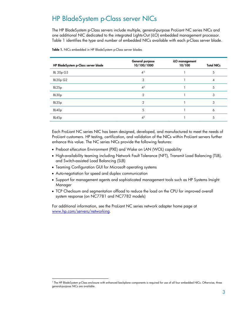
HP BladeSystem p-Class server NICs The HP BladeSystem p-Class servers include multiple, general-purpose ProLiant NC series NICs and one additional NIC dedicated to the integrated Lights-Out (iLO) embedded management processor. Table 1 identifies the type and number of embedded NICs available with each p-Class server blade.
Table 1. NICs embedded in HP BladeSystem p-Class server blades
HP BladeSystem p-Class server blade
General purpose 10/100/1000
iLO management 10/100
Total NICs
BL 20p G3 45 1 5
BL20p G2 3 1 4
BL25p 45 1 5
BL30p 2 1 3
BL35p 2 1 3
BL40p 5 1 6
BL45p 45 1 5
Each ProLiant NC series NIC has been designed, developed, and manufactured to meet the needs of ProLiant customers. HP testing, certification, and validation of the NICs within ProLiant servers further enhance this value. The NC series NICs provide the following features:
• Preboot eXecution Environment (PXE) and Wake on LAN (WOL) capability • High-availability teaming including Network Fault Tolerance (NFT), Transmit Load Balancing (TLB),
and Switch-assisted Load Balancing (SLB) • Teaming Configuration GUI for Microsoft operating systems • Auto-negotiation for speed and duplex communication • Support for management agents and sophisticated management tools such as HP Systems Insight
Manager • TCP Checksum and segmentation offload to reduce the load on the CPU for improved overall
system response (on NC7781 and NC7782 models)
For additional information, see the ProLiant NC series network adapter home page at www.hp.com/servers/networking.
5 The HP BladeSystem p-Class enclosure with enhanced backplane components is required for use of all four embedded NICs. Otherwise, three general-purpose NICs are available.
3
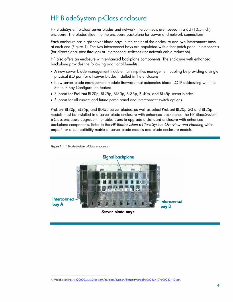
HP BladeSystem p-Class enclosure HP BladeSystem p-Class server blades and network interconnects are housed in a 6U (10.5-inch) enclosure. The blades slide into the enclosure backplane for power and network connections.
Each enclosure has eight server blade bays in the center of the enclosure and two interconnect bays at each end (Figure 1). The two interconnect bays are populated with either patch panel interconnects (for direct signal pass-through) or interconnect switches (for network cable reduction).
HP also offers an enclosure with enhanced backplane components. The enclosure with enhanced backplane provides the following additional benefits:
• A new server blade management module that simplifies management cabling by providing a single physical iLO port for all server blades installed in the enclosure
• New server blade management module firmware that automates blade iLO IP addressing with the Static IP Bay Configuration feature
• Support for ProLiant BL20p, BL25p, BL30p, BL35p, BL40p, and BL45p server blades • Support for all current and future patch panel and interconnect switch options
ProLiant BL30p, BL35p, and BL45p server blades, as well as select ProLiant BL20p G3 and BL25p models must be installed in a server blade enclosure with enhanced backplane. The HP BladeSystem p-Class enclosure upgrade kit enables users to upgrade a standard enclosure with enhanced backplane components. Refer to the HP BladeSystem p-Class System Overview and Planning white paper6 for a compatibility matrix of server blade models and blade enclosure models.
Figure 1. HP BladeSystem p-Class enclosure
6 Available at http://h20000.www2.hp.com/bc/docs/support/SupportManual/c00263417/c00263417.pdf.
4
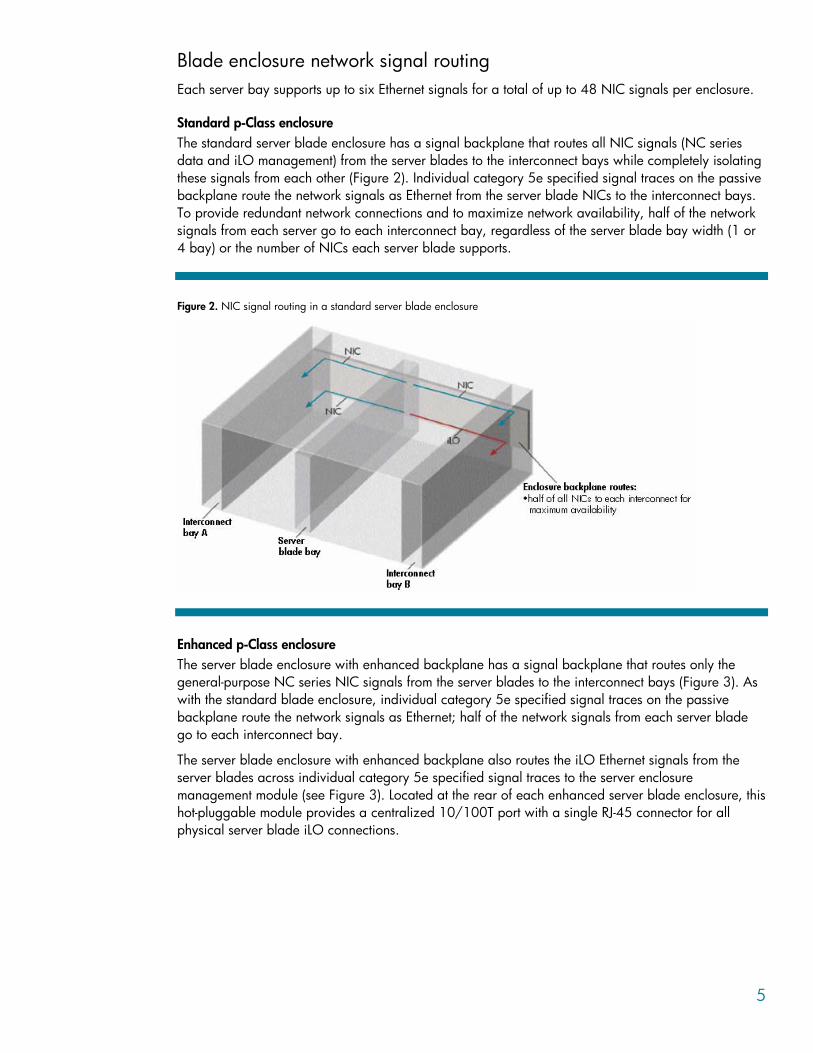
Blade enclosure network signal routing Each server bay supports up to six Ethernet signals for a total of up to 48 NIC signals per enclosure.
Standard p-Class enclosure The standard server blade enclosure has a signal backplane that routes all NIC signals (NC series data and iLO management) from the server blades to the interconnect bays while completely isolating these signals from each other (Figure 2). Individual category 5e specified signal traces on the passive backplane route the network signals as Ethernet from the server blade NICs to the interconnect bays. To provide redundant network connections and to maximize network availability, half of the network signals from each server go to each interconnect bay, regardless of the server blade bay width (1 or 4 bay) or the number of NICs each server blade supports.
Figure 2. NIC signal routing in a standard server blade enclosure
Enhanced p-Class enclosure The server blade enclosure with enhanced backplane has a signal backplane that routes only the general-purpose NC series NIC signals from the server blades to the interconnect bays (Figure 3). As with the standard blade enclosure, individual category 5e specified signal traces on the passive backplane route the network signals as Ethernet; half of the network signals from each server blade go to each interconnect bay.
The server blade enclosure with enhanced backplane also routes the iLO Ethernet signals from the server blades across individual category 5e specified signal traces to the server enclosure management module (see Figure 3). Located at the rear of each enhanced server blade enclosure, this hot-pluggable module provides a centralized 10/100T port with a single RJ-45 connector for all physical server blade iLO connections.
5
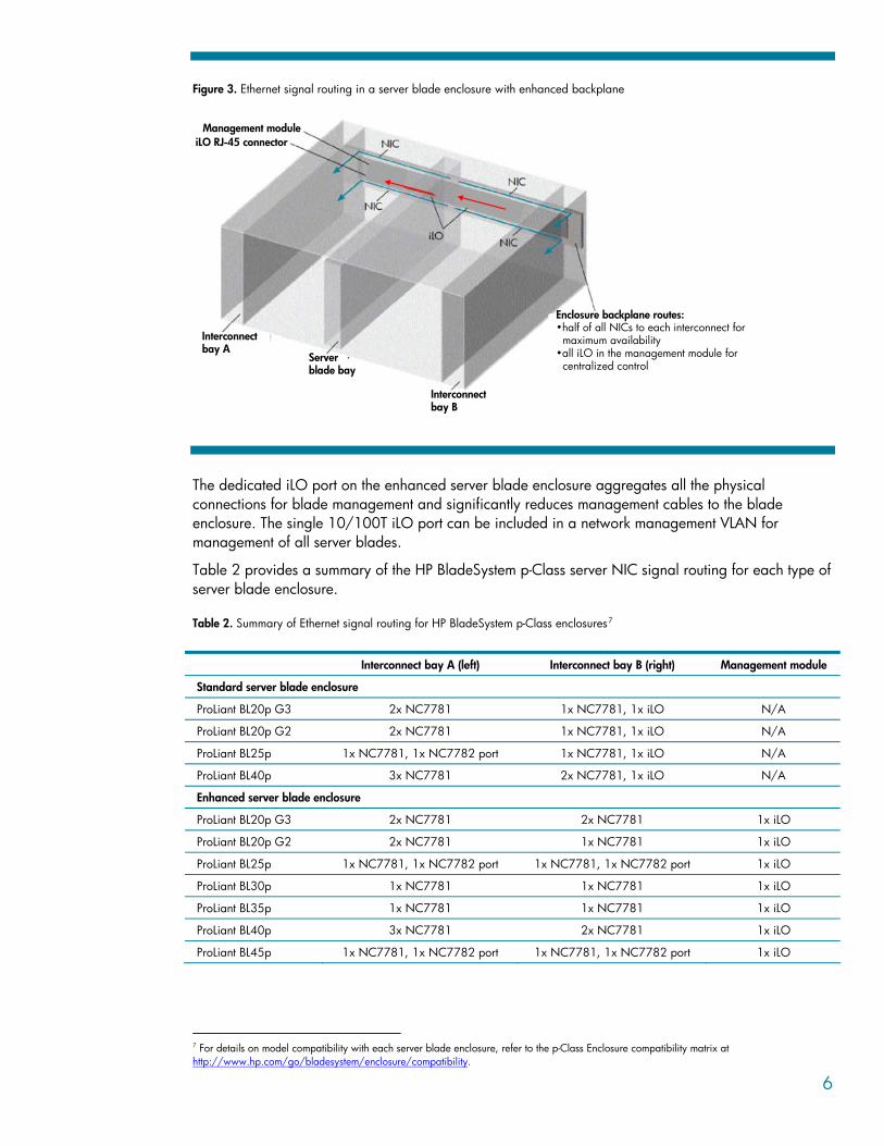
Figure 3. Ethernet signal routing in a server blade enclosure with enhanced backplane
Interconnectbay A
Serverblade bay
Interconnectbay B
Enclosure backplane routes:•half of all NICs to each interconnect for
maximum availability•all iLO in the management module for
centralized control
Management moduleiLO RJ-45 connector
The dedicated iLO port on the enhanced server blade enclosure aggregates all the physical connections for blade management and significantly reduces management cables to the blade enclosure. The single 10/100T iLO port can be included in a network management VLAN for management of all server blades.
Table 2 provides a summary of the HP BladeSystem p-Class server NIC signal routing for each type of server blade enclosure.
Table 2. Summary of Ethernet signal routing for HP BladeSystem p-Class enclosures7
Interconnect bay A (left) Interconnect bay B (right) Management module
Standard server blade enclosure
ProLiant BL20p G3 2x NC7781 1x NC7781, 1x iLO N/A
ProLiant BL20p G2 2x NC7781 1x NC7781, 1x iLO N/A
ProLiant BL25p 1x NC7781, 1x NC7782 port 1x NC7781, 1x iLO N/A
ProLiant BL40p 3x NC7781 2x NC7781, 1x iLO N/A
Enhanced server blade enclosure
ProLiant BL20p G3 2x NC7781 2x NC7781 1x iLO
ProLiant BL20p G2 2x NC7781 1x NC7781 1x iLO
ProLiant BL25p 1x NC7781, 1x NC7782 port 1x NC7781, 1x NC7782 port 1x iLO
ProLiant BL30p 1x NC7781 1x NC7781 1x iLO
ProLiant BL35p 1x NC7781 1x NC7781 1x iLO
ProLiant BL40p 3x NC7781 2x NC7781 1x iLO
ProLiant BL45p 1x NC7781, 1x NC7782 port 1x NC7781, 1x NC7782 port 1x iLO
7 For details on model compatibility with each server blade enclosure, refer to the p-Class Enclosure compatibility matrix at http://www.hp.com/go/bladesystem/enclosure/compatibility.
6
PXE Each NC series NIC on the HP BladeSystem server blades supports PXE; one NIC at a time may be PXE enabled. A specific NIC on each server is preselected as the default PXE NIC. Therefore, all the PXE enabled NICs are initially routed to the same interconnect. To enhance system availability, the ROM Based Setup Utility (RBSU) for HP BladeSystem server blades may be used to configure PXE-enabled NICs that are routed to different interconnects.
HP BladeSystem p-Class interconnects HP offers six p-Class interconnect options that allow customers to choose how Ethernet and Fibre Channel signals exit the server blade enclosure. These interconnect options include two ProLiant RJ-45 patch panel kits and four ProLiant interconnect switch kits. The two patch panel kits provide pass-through of network signals (RJ-45 Patch Panel Kit) or both network and Fibre Channel storage signals (RJ-45 Patch Panel 2 Kit), thus giving customers the flexibility to choose the network components they prefer. Alternatively, the four interconnect switch kits provide different levels of Ethernet switching functionality and Fibre Channel signal pass-through. Both the standard server blade enclosure and the enhanced server blade enclosure support all interconnect options.
In general, customers should choose the appropriate interconnect option based on the following criteria:
• The first-generation RJ-45 Patch Panel Kit provides non-blocking Ethernet signal pass-through. • The second-generation RJ-45 Patch Panel 2 Kit provides the same Ethernet signal pass-through as
the first-generation kit, plus it adds Fibre Channel signal pass-through for ProLiant BL20p, BL25p, BL30p, BL35p, and BL45p series server blades.8
• The first-generation C-GbE and F-GbE Interconnect Kits provide non-blocking consolidation of 100 Mb/s Fast Ethernet NIC signals for copper- and fiber-based networks, respectively.
• The second-generation C-GbE2 and F-GbE2 Interconnect Kits provide consolidation of 1000 Mb/s Gigabit Ethernet NIC signals, advanced network capabilities, future planned option upgradeability, and optional Fibre Channel storage signal pass-through for ProLiant BL20p, BL25p, BL30p, BL35p, and BL45p series server blades.
• The Cisco Gigabit Ethernet Switch Module (CGESM) provides 100 percent compatibility with Cisco network infrastructure, Cisco IOS management, and flexible choices between fiber and copper uplinks at the port level through the use of small form-factor pluggable (SFP) modules. The CGESM also supports the same Fibre Channel storage pass-through option as the GbE2 switch.
Each interconnect kit includes two interconnects for one server blade enclosure. Each interconnect itself consists of two hot-pluggable components, a front-loading interconnect blade and a rear-mounted interconnect module that contains the network connectors. This modular design provides two key benefits:
• The interconnect blade can be quickly and easily removed and replaced from the front of the rack without the need for recabling.
• The interconnect switches support copper or fiber Ethernet uplinks by using different interconnect modules. This design also allows the uplinks to be upgraded easily to future technology.
8 Fibre Channel pass-through on the BL20p series server blades is supported beginning with the BL20p G2 model.
7
RJ-45 Patch Panel and RJ-45 Patch Panel 2 kits The patch panel interconnects offer three significant benefits:
• They allow the customer to connect signals to their own LAN and SAN infrastructure components. • They are very economical. • They are completely passive and require no software or management.
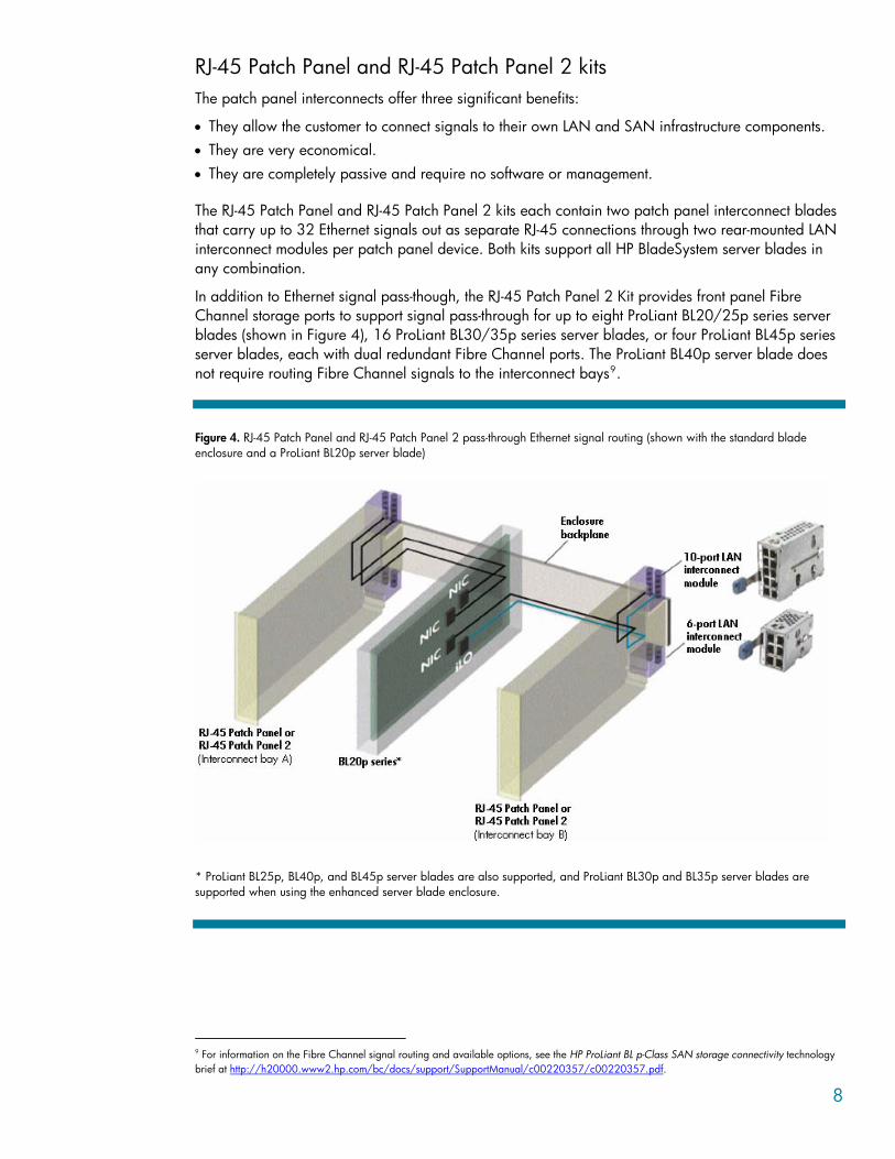
The RJ-45 Patch Panel and RJ-45 Patch Panel 2 kits each contain two patch panel interconnect blades that carry up to 32 Ethernet signals out as separate RJ-45 connections through two rear-mounted LAN interconnect modules per patch panel device. Both kits support all HP BladeSystem server blades in any combination.
In addition to Ethernet signal pass-though, the RJ-45 Patch Panel 2 Kit provides front panel Fibre Channel storage ports to support signal pass-through for up to eight ProLiant BL20/25p series server blades (shown in Figure 4), 16 ProLiant BL30/35p series server blades, or four ProLiant BL45p series server blades, each with dual redundant Fibre Channel ports. The ProLiant BL40p server blade does not require routing Fibre Channel signals to the interconnect bays9.
Figure 4. RJ-45 Patch Panel and RJ-45 Patch Panel 2 pass-through Ethernet signal routing (shown with the standard blade enclosure and a ProLiant BL20p server blade)
* ProLiant BL25p, BL40p, and BL45p server blades are also supported, and ProLiant BL30p and BL35p server blades are supported when using the enhanced server blade enclosure.
9 For information on the Fibre Channel signal routing and available options, see the HP ProLiant BL p-Class SAN storage connectivity technology brief at http://h20000.www2.hp.com/bc/docs/support/SupportManual/c00220357/c00220357.pdf.
8
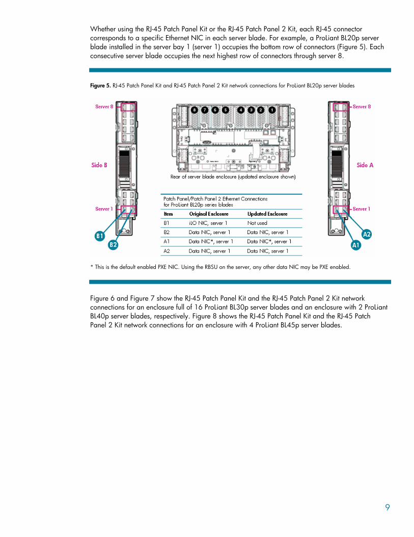
Whether using the RJ-45 Patch Panel Kit or the RJ-45 Patch Panel 2 Kit, each RJ-45 connector corresponds to a specific Ethernet NIC in each server blade. For example, a ProLiant BL20p server blade installed in the server bay 1 (server 1) occupies the bottom row of connectors (Figure 5). Each consecutive server blade occupies the next highest row of connectors through server 8.
Figure 5. RJ-45 Patch Panel Kit and RJ-45 Patch Panel 2 Kit network connections for ProLiant BL20p server blades
B1 B2 * This is the default enabled PXE NIC. Using the RBSU on the server, any other data NIC may be PXE enabled.
Figure 6 and Figure 7 show the RJ-45 Patch Panel Kit and the RJ-45 Patch Panel 2 Kit network connections for an enclosure full of 16 ProLiant BL30p server blades and an enclosure with 2 ProLiant BL40p server blades, respectively. Figure 8 shows the RJ-45 Patch Panel Kit and the RJ-45 Patch Panel 2 Kit network connections for an enclosure with 4 ProLiant BL45p server blades.
9
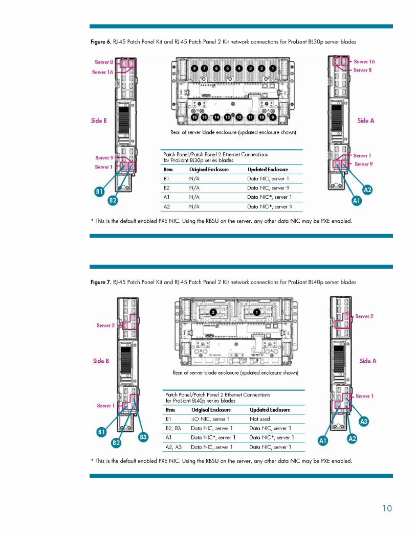
Figure 6. RJ-45 Patch Panel Kit and RJ-45 Patch Panel 2 Kit network connections for ProLiant BL30p server blades
* This is the default enabled PXE NIC. Using the RBSU on the server, any other data NIC may be PXE enabled.
Figure 7. RJ-45 Patch Panel Kit and RJ-45 Patch Panel 2 Kit network connections for ProLiant BL40p server blades
* This is the default enabled PXE NIC. Using the RBSU on the server, any other data NIC may be PXE enabled.
10
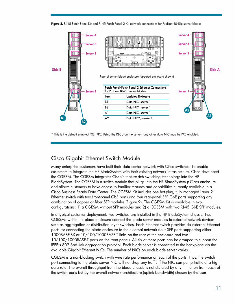
Figure 8. RJ-45 Patch Panel Kit and RJ-45 Patch Panel 2 Kit network connections for ProLiant BL45p server blades
Rear of server blade enclosure (updated enclosure shown)
Data NIC*, server 1A2
Data NIC, server 1A1
Data NIC, server 1B2
Data NIC, server 1B1
Updated EnclosureItem
Patch Panel/Patch Panel 2 Ethernet Connections for ProLiant BL45p series blades
Data NIC*, server 1A2
Data NIC, server 1A1
Data NIC, server 1B2
Data NIC, server 1B1
Updated EnclosureItem
Patch Panel/Patch Panel 2 Ethernet Connections for ProLiant BL45p series blades
A2
A1B1
Server 1
Side A
Server 2
Side B
1234
B2
Server 4
Server 3
Server 1
Server 2
Server 4
Server 3
A2
A1B1
Server 1
Side A
Server 2
Side B
1234
B2
Server 4
Server 3
Server 1
Server 2
Server 4
Server 3
* This is the default enabled PXE NIC. Using the RBSU on the server, any other data NIC may be PXE enabled.
Cisco Gigabit Ethernet Switch Module Many enterprise customers have built their data center network with Cisco switches. To enable customers to integrate the HP BladeSystem with their existing network infrastructure, Cisco developed the CGESM. The CGESM integrates Cisco’s feature-rich switching technology into the HP BladeSystem. The CGESM is a switch module that plugs into the HP BladeSystem p-Class enclosure and allows customers to have access to familiar features and capabilities currently available in a Cisco Business Ready Data Center. The CGESM Kit includes one hot-plug, fully managed Layer 2+ Ethernet switch with two front-panel GbE ports and four rear-panel SFP GbE ports supporting any combination of copper or fiber SFP modules (Figure 9). The CGESM Kit is available in two configurations: 1) a CGESM without SFP modules and 2) a CGESM with two RJ-45 GbE SFP modules.
In a typical customer deployment, two switches are installed in the HP BladeSystem chassis. Two CGESMs within the blade enclosure connect the blade server modules to external network devices such as aggregation or distribution layer switches. Each Ethernet switch provides six external Ethernet ports for connecting the blade enclosure to the external network (four SFP ports supporting either 1000BASE-SX or 10/100/1000BASE-T links on the rear of the enclosure and two 10/100/1000BASE-T ports on the front panel). All six of these ports can be grouped to support the IEEE’s 802.3ad link aggregation protocol. Each blade server is connected to the backplane via the available Gigabit Ethernet NICs. The number of NICs on each blade server varies.
CGESM is a non-blocking switch with wire rate performance on each of the ports. Thus, the switch port connecting to the blade server NIC will not drop any traffic if the NIC can pump traffic at a high data rate. The overall throughput from the blade chassis is not dictated by any limitation from each of the switch ports but by the overall network architecture (uplink bandwidth) chosen by the user.
11
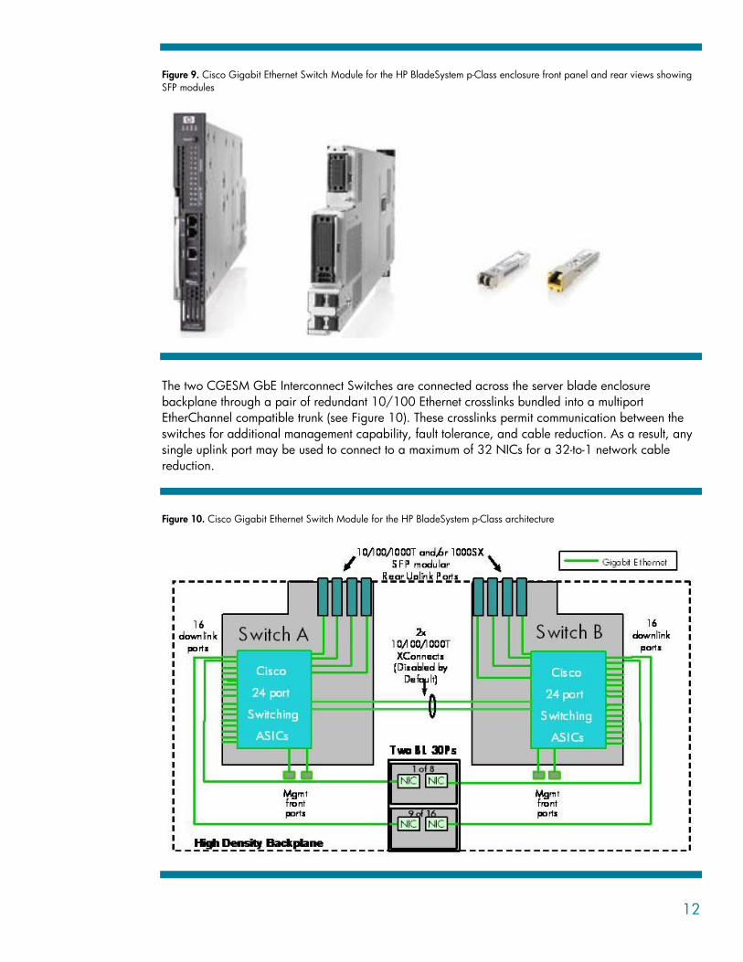
Figure 9. Cisco Gigabit Ethernet Switch Module for the HP BladeSystem p-Class enclosure front panel and rear views showing SFP modules
The two CGESM GbE Interconnect Switches are connected across the server blade enclosure backplane through a pair of redundant 10/100 Ethernet crosslinks bundled into a multiport EtherChannel compatible trunk (see Figure 10). These crosslinks permit communication between the switches for additional management capability, fault tolerance, and cable reduction. As a result, any single uplink port may be used to connect to a maximum of 32 NICs for a 32-to-1 network cable reduction.
Figure 10. Cisco Gigabit Ethernet Switch Module for the HP BladeSystem p-Class architecture
12
The redundant architecture of the CGESM allows system administrators to configure the Ethernet network for continued access to each server blade in case of the following failures:
• Interconnect switch failure • Switch failure within the Ethernet network backbone • Server blade network adapter failure • Server blade NIC-to-interconnect switch port failure or connection failure • Uplink port and uplink port connection or cable failure • Interconnect switch crosslink port or connection failure • Power or fan failure
For more information, see the HP p-Class CGESM Design Guide white paper.10
ProLiant GbE2 Interconnect Kit The second-generation ProLiant GbE2 Interconnect Kit is also designed to significantly reduce the number of Ethernet network cables attached to the rear of the server blade enclosure. However, it is designed for deployments that require network adapter consolidation to 1000 Mb/s (Gigabit Ethernet), advanced network functionality, future upgradeability including Layer 3 switching and 10-Gigabit Ethernet uplink bandwidth, and Fibre Channel storage signal pass-through.
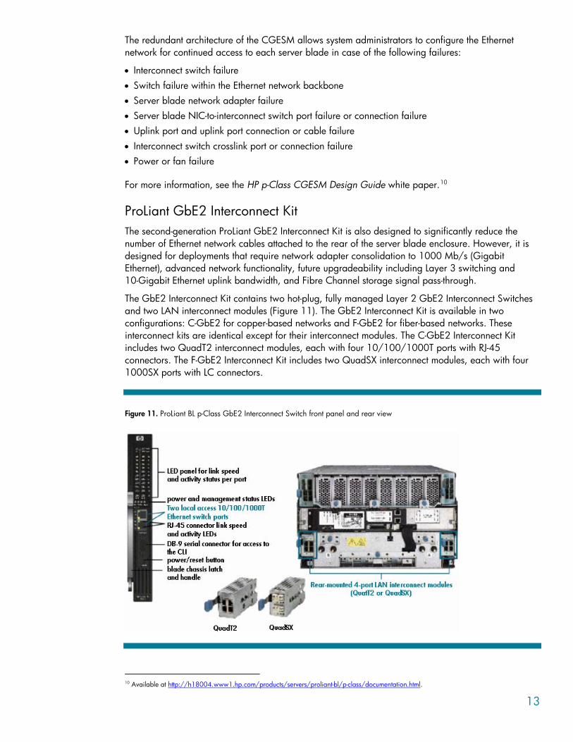
The GbE2 Interconnect Kit contains two hot-plug, fully managed Layer 2 GbE2 Interconnect Switches and two LAN interconnect modules (Figure 11). The GbE2 Interconnect Kit is available in two configurations: C-GbE2 for copper-based networks and F-GbE2 for fiber-based networks. These interconnect kits are identical except for their interconnect modules. The C-GbE2 Interconnect Kit includes two QuadT2 interconnect modules, each with four 10/100/1000T ports with RJ-45 connectors. The F-GbE2 Interconnect Kit includes two QuadSX interconnect modules, each with four 1000SX ports with LC connectors.
Figure 11. ProLiant BL p-Class GbE2 Interconnect Switch front panel and rear view
10 Available at http://h18004.www1.hp.com/products/servers/proliant-bl/p-class/documentation.html.
13
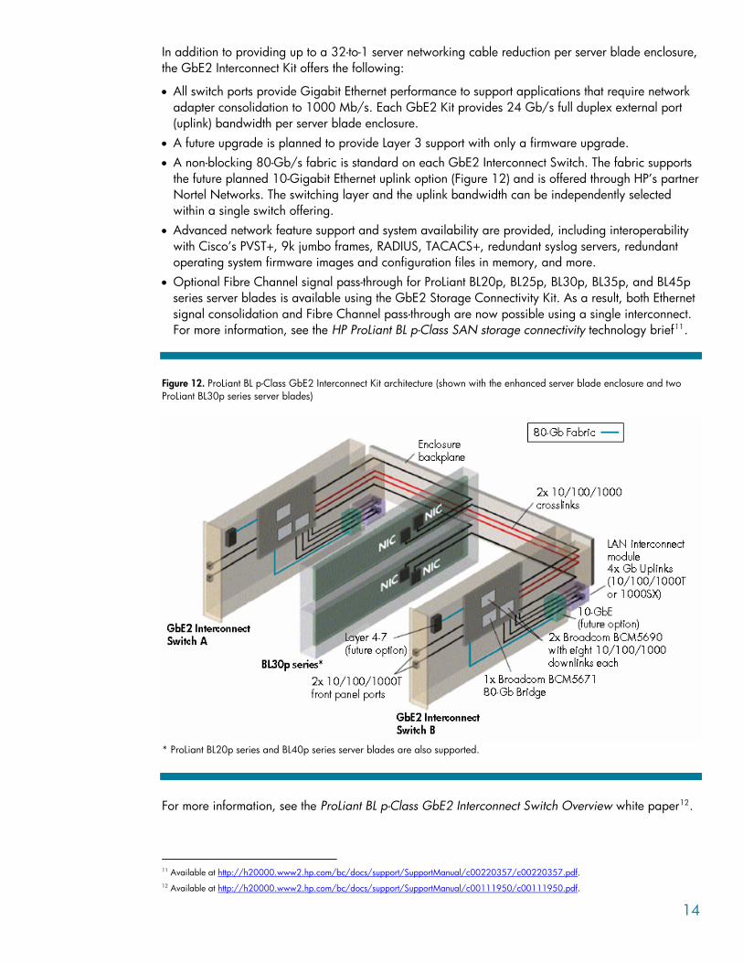
In addition to providing up to a 32-to-1 server networking cable reduction per server blade enclosure, the GbE2 Interconnect Kit offers the following:
• All switch ports provide Gigabit Ethernet performance to support applications that require network adapter consolidation to 1000 Mb/s. Each GbE2 Kit provides 24 Gb/s full duplex external port (uplink) bandwidth per server blade enclosure.
• A future upgrade is planned to provide Layer 3 support with only a firmware upgrade. • A non-blocking 80-Gb/s fabric is standard on each GbE2 Interconnect Switch. The fabric supports
the future planned 10-Gigabit Ethernet uplink option (Figure 12) and is offered through HP’s partner Nortel Networks. The switching layer and the uplink bandwidth can be independently selected within a single switch offering.
• Advanced network feature support and system availability are provided, including interoperability with Cisco’s PVST+, 9k jumbo frames, RADIUS, TACACS+, redundant syslog servers, redundant operating system firmware images and configuration files in memory, and more.
• Optional Fibre Channel signal pass-through for ProLiant BL20p, BL25p, BL30p, BL35p, and BL45p series server blades is available using the GbE2 Storage Connectivity Kit. As a result, both Ethernet signal consolidation and Fibre Channel pass-through are now possible using a single interconnect. For more information, see the HP ProLiant BL p-Class SAN storage connectivity technology brief11.
Figure 12. ProLiant BL p-Class GbE2 Interconnect Kit architecture (shown with the enhanced server blade enclosure and two ProLiant BL30p series server blades)
* ProLiant BL20p series and BL40p series server blades are also supported.
For more information, see the ProLiant BL p-Class GbE2 Interconnect Switch Overview white paper12.
11 Available at http://h20000.www2.hp.com/bc/docs/support/SupportManual/c00220357/c00220357.pdf. 12 Available at http://h20000.www2.hp.com/bc/docs/support/SupportManual/c00111950/c00111950.pdf.
14
Investment protection and interconnect flexibility The HP BladeSystem p-Class interconnect options are designed to support past, present, and future p-Class server blades. The HP BladeSystem p-Class enclosures support many different combinations of ProLiant BL20p, BL25p, BL30p, BL35p, BL40p, and BL45p series server blades and interconnect options. All HP BladeSystem p-Class interconnects further support both standard and enhanced server blade enclosures.
As needs and applications change, an interconnect option may be changed from a first-generation patch panel or interconnect switch kits to a second-generation kit. Likewise, any patch panel kit may be replaced with any interconnect switch kit (or vice versa).
Conclusion The networking design of the HP BladeSystem provides maximum flexibility and significant performance in an end-to-end redundant architecture. The network adapters included as standard with each server blade are routed to a pair of fully redundant, hot-swappable interconnects. HP offers a wide selection of interconnect kits for a choice of Ethernet cable consolidation and Fibre Channel signal pass-through. The economical patch panel kits allow network administrators to use the network switch or other components of their choice. The interconnect switches are ideal for reducing Ethernet network cabling and the time required to deploy, manage, and service HP BladeSystem solutions.
15

For more information For additional information, refer to the resources detailed below.
Resource description Web address
HP BladeSystem home page http://www.hp.com/go/blades
ProLiant BL p-Class white papers and documentation
http://www.hp.com/products/servers/proliant-bl/p-class/info
ProLiant NC series network adapter home page
http://h18004.www1.hp.com/products/servers/networking/index.html
ProLiant BL p-Class GbE2 Interconnect Switch Overview white paper
http://h20000.www2.hp.com/bc/docs/support/SupportManual/c00111950/c00111950.pdf
HP p-Class CGESM Overview white paper
http://h18004.www1.hp.com/products/servers/proliant-bl/p-class/documentation.html
HP p-Class CGESM Design Guide white paper
http://h18004.www1.hp.com/products/servers/proliant-bl/p-class/documentation.html
HP ProLiant BL p-Class SAN storage connectivity technology brief
http://h20000.www2.hp.com/bc/docs/support/SupportManual/c00220357/c00220357.pdf
ProLiant BL p-Class GbE and GbE2 Interconnect Switch user guides
http://welcome.hp.com/country/us/en/support.html
Call to action Please send questions and further comments about this paper to: [email protected].
© 2005 Hewlett-Packard Development Company, L.P. The information contained herein is subject to change without notice. The only warranties for HP products and services are set forth in the express warranty statements accompanying such products and services. Nothing herein should be construed as constituting an additional warranty. HP shall not be liable for technical or editorial errors or omissions contained herein.
TC050704TB, 07/2005