hp 561b manual - hp archive
TRANSCRIPT

HP Archive
This vintage Hewlett Packard document waspreserved and distributed by
www.hparchive.com
Please visit us on the web !
Scanned by on-line curator: Tony Gerbic
** For FREE Distribution Only ***

5618DIGITALRECORDER
OPERATING AND SERVICE MANUAL
HEWLETT. PACKARD

),
00165·3
OPERATING AND SERVICE MANUAL
MODEL 5618
DIGITAL RECORDER
SERIALS PREFIXED: 33.4-
This manual applies directly to standard ll-column and special12-column HP Model 561B Digital Recorders with serial numberprefix 334-. Appendix I lists the changes required to adapt thismanual to older instruments with serial prefix 241- or 038-.
Copy,ight HEWLETT·PACKARD COMPANY 196~
1501 PAGE MILL ROAD, PALO ALTO, CALIFORNIA, U.S.A.
Printed: JUN 1967
SECTION I
CONTENTS
DESCRIPTION AND INSTALLATION
Model 561B
PAGE
1 - 11 - 21 - 31 - 41 - 51 - 61 - 71 - 81 - 91 - 10
General Description . . .Power Cable . . . . . . .Unpacking and Power Connection .50-Cycle Operation. . . . . . . .Input Cable (Supplied) and ConnectorsConnecting to the Digital Voltmeter ..Connecting to I/fJ Electronic Counters .Cable Fabrication ..Special Data Sources.Multiple Inputs . . . .
I - 1I - 1I - 1I - 2I - 2I - 2I - 3I - 3I - 5I - 6
SECTION II OPERATION
2 - 12 - 22 - 32 - 42 - 52 - 6
Operating ControlsPaper Tape ...Inked Ribbon . . . .Tape Duplicates . .Operator MaintenanceDigital Voltmeter Readout.
II - 1II - 1II - 1II - 4II - 4II - 4
SECTION III THEORY OF OPERATION
3 - 13 - 23 -.33 - 4
Print Wheel PositioningTiming Sequence . . . .The Print Command Circuit.Power Supply . . . . . . . . .
III - 1III - 1III - 4III - 4
SECTION IV MAINTENANCE
4 - 14 - 24 - 34 - 4
Cabinet Removal. . . . . . .Printer Mechanism RemovalPeriodic MaintenanceTrouble Shooting . . . . .
IV - 1IV - 1IV - 1IV - 3
SECTION V TABLE OF REPLACEABLE PARTS
5 - 1 Table of Replaceable Parts V-I
APPENDIX I MANUAL CHANGES .....
ii
IA - 0
00165-3

)
Model 561B
\
DIGiTAl. RECORDER-. r$jJ ....'""" .-- -
\
00165-2
NOTICE ----------------,
THIS INSTRUMENT IS PARTLY MECHANICAL AND RE-
QUIRES PERIODIC CLEANING AND LUBRICATION FOR
DEPENDABLE SERVICE. THE PRINTER MECHANISM
SHOULD BE GIVEN A LIGHT CLEANING AFTER FOUR
PADS OF PAPER HAVE BEEN PRINTED; REFER TO
PARAGRAPH 2-5 OF THIS MANUAl. LUBRICATION IS
REQU IRED AFTER 100 HOU RS CONTINUOUS OPERATION
OR TWO MONTHS INTERMITTENT OPERATION; FOR
COMPLETE INSTRUCTIONS REFER TO YOUR PRINTER
MECHANISM MANUAl.
iii

Sect. 1 Page 0
COLUMN CAPACITY:
PRINT RATE:
PRINT WHEELS:
INPUT:
DRIVING SOURCE:
HOLD-OFF CONTROL:
INPUT IMPEDANCE:
PRINT COMMAND:
PAPER REQUIRED:
LINE SPACING:
POWER:
DIMENSIONS:
WEIGHT:
ACCESSORIES FURNISHED:
ACCESSORIES AVAILABLE:
Model 561B
SPECIFICATIONS
11 columns. (12 available on special order).
5 lines per second.
12 positions having numerals 0 through 9, a minus (-), and ablank. Other symbols are available on special order.
Decimal code, 10 lines plus 2 lines for blank and asterisk foreach column.
~ Electronic Counters (Models 5210, 521E, 523C, 524C) withrecorder kits and t$ Digital Voltmeters (Model 405), steppingswitches, relays, beam switching tubes, contact closures, or-15 to -100 volts connected to appropriate input wire.
SPOT relay to prevent external equipment from changing inputsignal while wheels are being positioned.
Approximately 270K ohms.
± 15 volts peak or more, 10 Jisec mInImUm width, 1 volt/Jisecminimum slope, or external contact closure. Manual controlby a momentary-contact sWitch.
~560A-131A (24 packets of HP 9281-0018) folded paper tape(15,000 prints with single spacing) or standard 3" roll tape.
Zero, single or double. In "ZERO", does not print.
115/230 ± 10% volts, 60 cps. Approximately 75 watts. 50 to 60cps (4 prints/second, maximum at 50 cps). 50 cps model available which retains 5 prints/second capability (spec. no. H03 -561B).
Cabinet Mount: 20-3/4 in. wide, 12-3/4in. high, 18-1/2in. deep.Rack Mount: 19 in. wide, 10-1/2 in. high, 16-1/2 in. deepbehind panel. Required rack depth is 20 in.
Cabinet Mount: Net 35 Ibs., shipping 70 Ibs.Rack Mount: Net 30 Ibs., shipping 65 Ibs.
One 561B-16A Cable, 6 ft. long, connects 561B with ~ equipmentproviding a 10-line code. Accommodates 6 columns.9281-0018 Folded Paper Tape, one packet9283-0002 Inked Ribbon560A-95N Digital Recorder service kit560A-37M Pin for paper tape roll~ 560A-131A 24 packet carton of ~ 9281-0018t$j> 9283-0002 Inked Ribbon folded paper tape.~ 560A-95N Service Kit~ 56lB-1M Cable~ 561B Digital recorder kits for field installation in ~ Elec-tronic Counters: ~ Counter Model ~Kit Number
5210, 521E 521D-95B523C 523C-95B524C 524C-95B
00165 -3

)
Model 561B Sect. I Page 1
SECTION IDESCRIPTION AND INSTALLATION
)
)
1-1 GENERAL DESCRIPTION
The Hewlett-Packard Model 561B Digital Recorderis an electro-mechanical printer with parallel entry to all columns which prints up to eleven columnsof data (12 columns available on special order) atrates up to five lines per second. This printing ratemakes the 561B ideal for recording rapidly changing data in digital form. Model 561B makes apermanent printed record of data from the <Fj, Model405CR Digital Voltmeter and from ~ in-line displayvacuum tube electronic counters having modification kits installed. The basic design allows the561B to be operated from beam switching tubes,stepping switches, relay matrices, and other datagathering systems using a 10-line code. Numeralso through 9, a minus (-) sign and a blank may beprogrammed in any column.
The Model 561B is supplied with a cable for operating directly with IJijJ Model 405AR Digital Voltmeter or with modified IJijJ Electronic Counterssuch as t$ Models 5210, 521E, 523CR and 524Cwhich have an in-line display. These countersmay be furnished with internal circuitry and receptacle for connecting to Model 561B DigitalRecorder, or kits may be obtained at a later datefor field installation.
Data entry to the 561B is through a separate wirefor each print wheel symbol. The input wiresand two control lines, called COMMON and BIASare brought out to connectors at the rear of the instrument. Both control lines are isolated from the561 chassis, allowing either line to be groundedor connected to any voltage from -600 to + 600,thus facilitating control from off-ground numberselecting sources, such as beam-switching tubes.
In addition to this manual, the following items areincluded with your 561tl Digital Recorder:
1) Printer Mechanism Service Manual (covers themechanical portion of 561B).
00165-3
2) 561B-16A 100 conductor cable, 6 feet long.
3) 560A-95N Service Kit (packed in paper compartment).
4) 9281-0018 Folded Paper Tape (packed in papercompartment) .
5) 560A-37M Pin for use with rolled paper tape(taped to bottom of paper compartment).
6) 9283-0002 Inked ribbon (installed).
1-2 POWER CABLE
The power cable of the 561B consists of threeconductors and is terminated in a three-prongmale connector recommended by the NationalElectrical Manufacturers' Association. The thirdcontact is an offset round pin added to a standardtwo-blade connector which grounds the instrumentchassis when used with an appropriate receptacle.To use the NEMA connector in a two-contact receptacle, a three-prong to two-prong adaptershould be used. When the adapter is used, thethird contact is terminated in a short green leadwhich should be grounded.
1-3 UNPACKING AND POWER
CONNECTION
If the shipping carton is damaged, ask that the carrier's agent be present when the instrument is unpacked. Inspect the instrument ·for damage(scratches, dents, broken knobs, etc). If theinstrument is damaged or fails to meet specifications notify the carrier and the nearest HewlettPackard field office immediately (field offices arelisted at the back of this manual). Retain the shipping carton and the padding material for the carrier's inspection. The field office will arrange forthe repair or replacement of your instrument without waiting for the claim against the carrier to besettled.

Sect. I Page 2 Model 561B
The r§lJ Model 561 B can be operated from either 115or 230-volt 60 cps power lines. Slide switch S101on the instrument rear panel permits quick conversion for operation from either voltage. Inserta narrow-blade screwdriver in the switch slot andslide the switch to the right for 230-volt operation("230" marking exposed) and to the left ("115"marking exposed) for 115 -volt operation. Fuse F1should be a 1. 25 ampere, slow-blow type for 115volt operation or a 0.6 ampere, slow-blow type for230-volt operation.
1-4 50-CYCLE OPERATION
The 561B will operate from a 50-cycle sourceat slightly reduced speed. The normal maximumof five prints per second will be reduced to four.A special motor pinion gear is available whichcorrects for the reduced motor speed to providefive prints per second from a 50-cycle source.Refer to your Printer Mechanism Manual for piniongear information.
1-5 INPUT CABLE (SUPPLIED) ANDCONNECTORS
The lOa-conductor cable supplied with the 561Bis used to conveniently connect the 561B with theI$jJ Model 405CR Digital Voltmeter or r§lJ electroniccounters equipped with a modification kit. Connectors on each end of the cable are identicalso either end of the cable may be connected tothe 561B.
The PRINT COMMAND switch, located betweenJlOl and J102, must be operated toward the connector which supplies print commands.
1-6 CONNECTING TO THE DIGITALVOLTMETER
Data from the diJ Model 405CR Digital Voltmetermay be recorded by connecting the 405CR to the561B with the lOa-conductor cable supplied withthe 561B. Connect one end of the cable to J3 onthe Model 405CR. Connect the other end of thecable to either JlOl or Jl02 on the 561B. If JlOlis used, the 561B will print on columns one throughsix (the six right-hand columns). If Jl02 is used,the 56lB will print on columns seven througheleven. Be sure to operate the PRINT COMMANDswitch on the connector mounting plate toward theinput jack connected to the Digital Voltmeter.
CAUTION
THE COMMON LINE OF THE 561B IS A FLOATING GROUND. IT ASSUMES THE POTENTIALOF ANY SOURCE TO WHICH IT IS CONNECTED.WHEN THE DIGITAL VOLTMETER OR AN ELECTRONIC COUNTER IS USED WITH THE 561B,A POTENTIAL OF ABOUT + 115 VOLTS IS EST ABLISHED ON THE COMMON LINE.
If a supplementary programming device is connected to COMMON, its ground return must beat the potential determined by the counter ordigital voltmeter. Avoid low impedance circuitsto chassis ground which may upset indicating circuits in the counter or voltmeter. See Figure 1-1.
Cable wiring consists of a connection between eachpin in one connector and the identically numberedpin in the other connector. Pins 48 and 49 of theupper connector (print command input) are shielded;the shield is connected to pin 50 (ground).
c!iJDIGITAL VOLTMETER
ORELECTRONIC COUNTER
c!iJ5618
+300V
Figure 1-1. COMMON at Potential Determined by Data Source
00165·3
COMMON(BUS
>b---l,-t115V ON,rPINS 138 38ALL CONNECTORS L..--------;R:-;:JO
PART OFIOO-CONDUCTOR~ABLE
<+1I5V~
External number selecting circuitry is connectedto the 56lB through two lOa-pin connectors, J101and Jl02, located on the rear of the chassis. Printing in columns one through six (the six columnson the right when facing the front of the instrument) is controlled through Jl01; printing incolumns seven through eleven (the five columnson the left) is controlled through Jl02. An inputfrom a six column source normally would be connected to Jl01, but may be connected to J102 withthe loss of the most significant digit (i.e. thedigit in the left hand column).

)
Model 561B
1-7 CONNECTING TO rf/J ELECTRONICCOUNTERS
The 561B may be lJperated directly from ~ electronic counters having an in-line display such as~ Models 5210, 521E, 523C, and 524C. Thesecounters can have the necessary kits installedat the factory or kits may be obtained for fieldinstallation.
To record data from a modified ~ electroniccounter, simply connect an IJiiJ lOa-conductor cablebetween the lOa-pin output connector on the counterand JIOl or JlO2 on the 56lB. The <f$, Model 523Cprovides a six-digit output and normally would beconnected to nOl. The 524C provides an eightdigit output requiring the use of two lOa-conductorcables and both input connectors on the 56lB.
Be sure to operate the PRINT COMMAND switchtoward the appropriate input connector.
Read CAUTION notice in paragraph 1-6. Referto Figure 1-1.
60 WATTSOLDERING
IRON~
#14 GA. TINNED
COPPER WIRE~
ABOUT 2 IN. LONG
Sect. I Page 3
1-8 CABLE FABRICATION
Connection of the 561B to data sources other thanthe IJiiJ Model 405CR Digital Voltmeter or modifiedI/ij; counters may require construction of a cableterminated with a connector which will mate withnOl or J102. Procurement instructions for cablesand connectors are given in Section V, Table ofReplaceable Parts.
Use small gage telephone-type wire. Number 26gage wire meeting MIL-B-76A, with 7 strands #34gage wire, tinned after stranding, with 105 0 Cplastic insulation, has been found satisfactory.Print command input wires should be shielded.
Select a systematic color code for wires to avoiderrors. Use care in soldering. Repairing faultyconnections after all wires are connected is verydifficult.
A piece of #14 gage wire makes an excellentsoldering tip for use on closely-spaced connectorterminals. See Figure 1-2.
)Figure 1-2. Wire Soldering Tip
00165-3

Sect. 1 Page 4 Model 5618
06 ? 0,6 I
23 ONE4 Of
PROGRAMMING 5 ELEVENSWITCH
w I 6PROGRAMMING 7 PRINT WHEEL
40
SWITCH CONTROLB9 CIRCUITS
50
BLANKDISABLING
JUMPER \,.- -43VBIAS
PRINT -ICOMMANDNEGATIVESWITCH 9 PRINT
PRINT CONNANDCOMMAND INPUT) AND
CLUTCH CONTROLCI RCUITS
BD-M-86
B+
BEANSWITCHING
TUBE
TO BEAMSWITCHING
TUBE
BLANKDISABLING
JUMPER \,.
ONEOf
ELEVENPRIHT WHEEL
CONTROLCIRCUITS
COMMON
NEGATIVE PRINT COMMAND INPUT
INPUT
PRINT CONNANDAND
CLUTCH CONTROLCIRCUITS
Figure 1-3. External Programming Systems

)
Model56lB
1-9 SPECIAL DAY A SOURCES
This paragraph discusses the following importantfactors which must be considered when connectingthe 56lB to a data source other than r.§t; digitalindicating equipment:
a) Input connections must be made to deliverprint wheel positioning data to the 561 B.
b) Print wheels with no input are automaticallyprogrammed to the BLANK position. Externaljumper must be installed to prevent print wheelsfrom locking in the BLANK position.
c) External number selecting system must providea print command signal each time a number isto be printed. When positive print command isless than +115 volts, install. 01 /If capacitorin series with this input. Negative print command possible by switching this input to groundor to -43 V line.
d) The external system must be connected to the561 B disable relay or counter disable pulse(see Table 1-2) so that the number selectionwill not be changed while the relay is energized.
A. PROGRAMMING
One means of programming a print wheelsymbol is to externally connect the BIAS line (-43v)to the appropriate input terminal as indicated
Sect.! Page 5
in the Tables 1-1 and 1-2. This method may beused with relay matrices, stepping switches, andother contact closure systems.
Another programming method is to connect -15 to-100 volts between the COMMON BUS and the inputterminal of the number to be printed. For example,to print data from a beam-switching tube, connectits B+ to the COMMON BUS and its targets to theappropriate input terminal. Refer to Figure 1-3.
B. BLANK
A 22K resistor is internally connected betweenthe BIAS line and the BLANK input. This programsunused print wheels to the no-print or BLANKposition, preventing random printing by wheelswhich are not connected to an external numberselecting circuit. To program symbols other thanBLANK, a shorting jumper must be installed between the BLANK input and COMMON. The jumpermay be installed on the external connector at the56lB, or if the BLANK input terminal is connectedto the output of the driving equipment, the shortingjumper may be installed there. Refer to Figure 1-3.
A print wheel which has had the BLANK positiondisabled by an external jumper may be programmeuto any position except BLANK. To enable externalcircuitry to program BLANK, remove the BLANK
TABLE 1-1. PRINT WHEEL CONNECTIONS
Print JI02B n02A JIOlB nOlAWheelSymbol 11 10 9 8 7 6 5 4 3 2 1
0 25 1 26 25 1 26 25 1 26 25 1
1 24 2 27 24 2 27 24 2 27 24 2
2 23 3 28 23 3 28 23 3 28 23 3
3 22 4 29 22 4 29 22 4 29 22 4
4 21 5 30 21 5 30 21 5 30 21 5
5 20 6 31 20 6 31 20 6 31 20 6
6 19 7 32 19 7 32 19 7 32 19 7
7 18 8 33 18 8 33 18 8 33 18 8
8 17 9 34 17 9 34 17 9 34 17 9
9 16 10 35 16 10 35 16 10 35 16 10
- 15 11 36 15 11 36 15 11 36 15 11
BLANK 14 12 37 14 12 37 14 12 37 14 12
QCONNECTORCOLUMN
QPRINT WHEEL
PINNUMBER
) 00165-2

Sect. I Page 6
disabling jumper and disconnect the appropriate22K resistor. The 22K resistors are located ona resistor board on the connector mounting plateat the rear of the 561B chassis. The wheel whicha given resistor affects may be identified by thelast two digits of the designation printed on theresistor board. For example, R107 programsBLANK in column seven (seventh wheel from theright as viewed from the front of the instrument).
TABLE 1-2. CONTROL CONNECTIONS
DescriptionPin
ConnectorNumber
COMMON nOlA, J101B(Floating ground) 13, 38 n02A, n02B
CHASSIS(Power line ground) 50 nOlA, n02A
BIAS 39,41,44 nOlA n02A(-43 volts) 48,49,50 n01B, n02B
PRINT COMMAND
lNEGATIVE 48POSITIVE 49
RELAY K1 nOlANORM CLOSED 45 n02ACOMMON ARM 46 JNORM OPEN 42
COUNTER DISABLE 47
C. PRINT COMMAND
The external system must provide a printcommand pulse to initiate a printing cycle eachtime a number is to be printed. This pulse maybe either positive or negative, and it must be atleast 15 volts in amplitude and 10 microsecondsin duration. Rise time of the pulse should be atleast one volt per microsecond. The pulse may beobtained from an external pulse circuit or bymomentarily shorting the BIAS line to the NEGATIVE PRINT COMMAND input. See Figure 1-3.
To prevent noise pickup from starting unwantedprinting cycles, terminate the unused print command input with a resistor whose value is approximately equal to the source impedance of the printcommand circuit. For example, if a negative pulsegenerator with an output impedance of 200,000 ohmssupplies the print command pulse to pin 48 of nOlA,connect a 200,000-ohm resistor between pins 49and 38 of J101A.
Model 561B
D. SOURCE DISABLE
Accurate print wheel positioning requires thatthe data source be prevented from changing numberselections during the printing cycle. Relay Kl isincluded to disable external number selecting circuits. The relay is energized at the beginning ofthe printing cycle. The external number selectingcircuit can be disabled during the printing cycleby connecting its supply voltage through the normally closed contacts of the relay. Maximum potential across open contacts: 200 volts. Maximumcurrent through relay contacts: 50 milliamperes.It may be necessary to add a resistor in serieswith the contacts to prevent excessive. cablecapacity charging currents.
The counter disable pulse (see Table 1-2) mayalso be used to disable special data sources. Thepulse is about 160 milliseconds in duration, risesfrom zero to an open-circuit VOltage of +240 volts(internal impedance lOOK).
1-10 MULTIPLE INPUTS
Successful data recording from two or more sourcesrequires that the data sources be timed or synchronized in such a way that data from each sourceis ready for printing when the 561B receives aprint command signal.
It is important that the entire system external tothe 561B selects and holds data which is fed tothe 561B. Each source must continue to hold itsdata output until the completion of the 561B printing cycle.
After all data has been presented to the 561B,some element of the external system must provide a print command signal to the 561B.
CAUTION
THE COMMON LINE OF THE 561B IS A FLOATING GROUND. IT ASSUMES THE POTENTIALOF ANY SOURCE TO WHICH IT IS CONNECTED.USE CAUTION WHEN CONNECTING SEVERALDATA SOURCES TO THE COMMON LINE.
The details of every multiple-source recordingsystem will naturally be different for each application. If complex systems are contemplated,contact your IFj; representative for assistance.

)
Model 56lB
2-1 OPERATING CONTROLS
Operation of front panel controls of the 56lB isshown in Figure 2-1.
The PRINT COMMAND switch (SIal) is mountedbetween JlOl and Jl02 on the connector mountingplate at the rear of the 56lB chassis. Operatingthe switch toward nOl supplies the 56lB withprint command signals from the data source connected to JlO1. Operating the switch toward n02supplies the 56lB with print command signalsfrom the data source connected to Jl02.
2-2 PAPER TAPE
Special ~ folded tape is recommended for usewith your recorder. High-quality standard 3-inchrolled adding machine type may also be used.
Folded tape permits convenient take-up in thepaper drawer and allows easy inspection of anyportion of the tape. It is perforated at each foldto allow neat separation of portions of recordeddata. Folded tape may be reversed and re-runto use both sides. With single spacing, about 15,000prints can be made on one side of a folded pad.One pad will last about 40 minutes at maximumprint rate.
Follow the instructions in Figure 2-2 to loadfolded paper tape. Follow these additional instructions if roll tape is used:
1) Insert spindle through roll. Spindle is tapedto bottom of paper compartment when instrumentis shipped from the factory.
2) Hang roll by ends of spindle from ledges onboth sides of paper compartment.
3) Paper must feed out from the bottom of theroll.
Sect. II Page 1
SECTION IIOPERATING INSTRUCTIONS
4) Continue with loading as shown in Figure 2-2.
To feed paper rapidly use the PAPER ADVANCEthumb wheel. To manually feed paper backward,set the SPACE SELECTOR to "0" and roll thePAPER ADVANCE wheel in the reverse (up)direction. Paper feed may be reversed onlywith the SPACE SELECTOR set to "0".
Be sure paper is inserted squarely in the paperfeed mechanism to prevent jamming. If paperdoes not feed smoothly, place the RECORD switchin the center position, and remove all paper fromthe feed mechanism. Use tweezers to pick outtorn bits of paper. Re-thread paper as shown inFigure 2-2 and resume printing.
2-3 INKED RIBBON
All models of the printer mechanism use a specialheavily-inked silk ribbon available from theHewlett-Packard Company. Standard typewriterribbon on an Underwood spool, with reversingrivets near the ribbon ends, may also be used;however, impressions will be lighter than with theHewlett-Packard ribbon.
To install new ribbon, proceed as follows:
1) Open the hinged front panel to gain access tothe printer mechanism.
2) Loosen the two printer mechanism retaIningscrews located on the lower front corners of themechanism by turning 1/4 turn counterclockwise.
3) Slide mechanism out of cabinet until ribbonspools are readily accessible.
4) Wind all the ribbon onto one spool.
5) Shift the two ribbon spool retaining springsaway from the spools, and remove spools.

Sect. II Page 2
FRONT PANEL CONTROLS
Model 5618
2
DIGITAL RECORDER
WOOtl ct1J ..'•HE 'ACUltDHU illL'" u.ur.....
1. POWER switch turns on line power to allcircuits.
2. PANEL HANDLE is used to open hinged frontpanel for paper tape or inked ribbon replacement.
3. RECORD switch controls printer mechanism.
Center position: Printer is in standbyoperation.
Up Position (ON): Printer will print one linefor each print command pulse received.
Down position (momentary): Printer willprint at maximum rate (print commandpulse not required).
4. SPACE SELECTOR thumb wheel selectsline spacing.
"0" or no-print position allows paper to berolled forward or backward.
" 1" or single space position advances paperone space for each printed line.
"2" or double space position advances papertwo spaces for each printed line.
5. PAPER DRAWER is used to collect foldedpaper tape after printing.
6 . PAPER ADVANCE thumb wheel allows manualpaper advance. Paper can be moved backward if SPACE SELECTOR is set at "0".
Figure 2-1

)
Mcxle15618 Sect. II Page 3
LOADING PAPER TAPE
1. Open front panel.
-----::::==••._...'A'" D'.WII---------==--
V IN••• • '.'ON
-_.::-_---~
-9)J,,/...,~
;~ ••••• eu'.t
-~-----~ ' ....
4. Manually advance paper. Paper will feedeasier and can be reversed with SPACE SELECTOR set to "0".
2. Load paper in compartment.
3. Fold paper back one inch and crease. Insertpaper between roller and guide plate.
5. Feed paper under inked ribbon.
6. Feed paper through slot. Close front panel.
7. Collect printed paper in drawer.
)
Figure 2-2
RO

Sect. II Page 4
6) Take the ribbon out of the mechanism. Savethe empty spool.
7) Hook end of new ribbon on empty spool. Windabout 10 inches of ribbon on the spool so that thereversing rivet is on the spool.
8) Install new ribbon by feeding it over the ribbonrollers and between the print wheels and papertape.
9) Feed ribbon through the slots in the reversingarms and around the lower guides. Ribbon mustbe twisted 90 0 between the ribbon roller and theslot in the reversing arm.
10) Place ribbon spools on their shafts. Fastenspools in place with the spool retaining springs.Ribbon must feed out from the bottom of each spool.
11) Replace printer mechanism in cabinet andtighten retaining screws.
2-4 TAPE DUPLICATES
You may have a need for duplicate tape records.Contact print duplicating methods, such as theOzalid process, can be used by printing directlyfrom the original tape records. For Ozalid (Diazo)copies, HP 560A-131B (24-packet carton) translucent paper is recommended.
Model 56lB
Place a four inch piece of paper under the printwheels during cleani!1g to prevent dirt from failing into the mechanism. Clean the print wheelswith plastic type cleaner only. Suitable typecleaner is intluded in your service kit. Pressthe type cleaner against the print wheels. Cleanthe type cleaner by folding dirty portions to thecenter of the cleaner.
WARNING
DO NOT USE SOLVENT TO CLEAN PRINTWHEELS. DO NOT USE A BRUSH TO CLEANTYPE FACES. DAMAGE TO THE PRINT WHEELMECHANISM MAY RESULT.
Give the printer mechanism a light cleaning eachtime the paper is changed. Simply wipe out paperdust which has accumulated in the paper compartment and on other accessible parts of themechanism.
NOTICE
LUBRICATION OF THE PRINTER MECHANISMIS REQUIRED AFTER 100 HOURS OF CONTINUOUS OPERATION OR TWO MONTHS OFINTERMITTENT OPERATION. FOR COMPLETEINSTRUCTIONS REF ER TO YOUR PRINTERMECHANISM MANUAL.
2-6 DIGITAL VOLTMETER READOUT
The following examples indicate proper interpretation of recorded information from the Model405AR Digital Voltmeter:
Five columns are used to record data from the~ Model 405AR Digital Voltmeter. Three significant figures are recorded. Polarity is indicatedby a minus sign for a neg~tive voltage and ablank for a positive voltage. Decimal position isindicated by a code number giving the number ofdigits to the right of the decimal.
Quality of copies is greatly improved by treatingthe original tape record to increase its translucency. Use a compound such as II Transparentizer"made by the Technifax Corporation,Holyoke, Mass.
2-5 OPERATOR MAINTENANCE
Inspect print wheels frequently when the printeris in use. Print wheels should be cleaned whenan accumulation of ink and dust builds up on thetype faces. It is good practice to clean the printwheels after every fourth pad of paper has beenprinted. Failure to clean ink from the printwheels may let ink get onto the print wheel pawlsand commutator contact surfaces, resulting insluggish pawl operation and misprinting.
284-1580 2842 0101-3
-28.4 volts+ 5.80 volts+ 842 volts-0.101 volts
00165-3
Model 561B Sect. III Page 1
)
SECTION IIITHEORY OF OPERATION
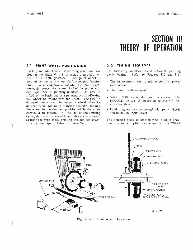
3-1 PRINT WHEEL POSITIONING 3-2 TIMING SEQUENCE
)
Each print wheel has 12 printing positions, including the digits 0 to 9, a minus sign and a noprint or BLANK position. Each print wheel isrotated by the print wheel shaft through a frictionclutch. A locking pawl associated with each wheelnormally keeps the wheel locked in place withone type face in printing position. The pawl islifted at the beginning of a printing cycle, allowingthe wheel to rotate with the shaft. The pawl isdropped into a notch in the print wheel when thedesired type-face is in printing position, lockingthe wheel in the desired position while the shaftcontinues to rotate. At the end of the printingcycle, the paper tape and inked ribbon are pressedagainst the type face, printing the desired character on the paper. Refer to Figure 3-1.
The following conditions exist before the printingcycle begins. Refer to Figures 3-2 and 3-3.
- The drive motor runs continuously after poweris turned on.
- The clutch is disengaged.
- Switch S302 is in the position shown. TheRECORD switch is operated to the ON position as shown.
- Pawl magnets are de-energized; print wheelsare locked by their pawls.
The printing cycle is started when a print command pulse is applied to the appropriate PRINT
CORK WASHER
PRINT WHEEL
LD-L-277
DRIVING PLATE
PRINT WHEELSHAFT
SPRING WASHER
DRIVEN PLATEKEYED TO PRINT WHEEL
)Figure 3-1. Print Wheel Operation

Sect. III Page 2 Model 561B
COMMAND input terminal. The pulse may besupplied by external pulse circuitry or generatedby momentarily shorting the NEGATIVE PRINTCOMMAND input to the BIAS line.
The print command pulse is amplified, and a positive triggering pulse is sent to the thyratroncontrol grid.
The thyratron is triggered into conduction, energizing the clutch solenoid. Notice that the clutchsolenoid may be energized and a printing cycleinitiated in absence of a print command pulse byoperating the RECORD switch to the momentaryposition.
The clutch is engaged, and the cam shaft and printwheel shaft begin to turn. The clutch is constructedso that it will remain engaged for only one re-volution per print command. -
After 200
of clutch rotation, S302 is operated bythe switch cam:
a) The normally closed contacts open, haltingthyratron conduction and de-energizing the clutchsolenoid. The clutch remains engaged until thecompletion of the printing cycle.
b) The normally open contacts of S302 close, supplying B+ to control tubes and energizing pawlmagnets for all print wheels not in proper position. The pawls are lifted, and the print wheelsare free to turn.
If the initial position of the print wheel is correct,the brush applies cut-off bias to the control tubeat the beginning of the printing cycle. The pawlmagnet will not energize, and the print wheel willnot rotate.
c) The closing of the normally open contacts alsoenergizes the disable relay. External number
MOMENTARY
1
GEARDECREASES
SHAfTSPEED
II
II CLUTCHI
_J. EN'A'ES FOR _ONE REVOlUTION
WHEN ACTUATED
tf240V
S302
MECH. CONTROLOF
PRINT BARPAPER ADVANCE
RIBBON ADVANCE
DIFFERENTIALAMPLIFIER
Jl
SWITCH CAMOPERATES S302
- DURING ZOO TO300' OF SHAfT
ROTATION
GEARINCREASES
SHAfTSPEED
DISABLERELAY
PAWLMAGNET
lCOUNTER .c'I DISABLESIGNAL
MAGNETCONTROL
TUBEjlLTHRU V6
>COMMON 1
PAWL
ONE OF .•IELEVENPRINT WHEEL d
CIRCUITS
..... NEGATIVE PRINT COMMAND INPUT,! 0--:;> >-'-=..;.;..;..;..=...;.....;.;.;.;.~~c.:.:.;..;.;..;.::;....'-'-'-'--"-'---------i
PRINTCOMMAND >-'P'-'O"-'S::.:.I.:..TI:...:.V-=E'-'-PR:.:.I:.:.;N:.:.T....:C"-'O::..:;M:.:.:.M:.:.;A::.;N.:.:D:o...:..:.IN.:..:.P...::U'-'T ----iSWITCH
BO-M-B5
Figure 3-2. Simplified Recorder Diagram

Mode156lB
TIME 0 50MS lOOMS 150MS
Sect. III Page 3
200MS
.... CLUTCH ENGAGES CLUTCH DISENGAGES -+
1 PRINT COMMAND PULSE
2 CLUTCH SOLENOIDENERGIZED
3 CAMSHAFT ROTATES
4 MECHANICAL DELAY
5 S302 OPERATES
6 PRINT WHEELS ROTATE,LOCK IN CORRECT POSITION
7 PRINTING OPERATION(PRINT ARN NOVES UP)
8 PAPER ADVANCES(PRINT ARN NOVES DOWN)
9 RIBBON ADVANCES 11111 IIIII
•,
•CAM ANGLE 0 0
Figure 3-3. Timing Sequence
3600
G-M-79A
)
)
selecting circuitry has been connected to the relaycontacts, to prevent number selections from beingchanged while the relay is energized.
The print wheels rotate on the print wheel shaft,seeking the position selected by the external circuitry. Each wheel carries a brush which makescontact with segments on an adjacent commutator.
External programming circuitry has previouslyconnected the BIAS line to the desired input segmentof each commutator. The desired type-face is inprinting position when the brush makes contactwith the segment to which the BIAS line has beenconnected.
When brush contact is made with the segment connected to the BIAS line, -43 volts is applied to thegrid of the control tube. Plate current is cut off,and the pawl magnet is de-energized, allowingthe pawl to drop into a notch on the print wheel.The print wheel is now locked in the correct position. The clutch between the wheel and the printwheel shaft slips until completion of the printingcycle. Each wheel is locked independently in theabove manner.
Print wheels which have no input are automaticallyprogrammed to the BLANK position. A 22K resistor is internally connected between the BLANKinput of each wheel and the BIAS line. Cut-offbias is delivered through the commutator to theprint wheel magnet control tube when the print
wheel is in the BLANK position, locking the printwheel. When a print wheel is connected to anexternal data source, a shorting jumper must beinstalled externally between the BLANK inputand the COMMON line, preventing BLANKprogramming.
All print wheels are correctly positioned afterthe print wheel shaft has made one revolution.The cam shaft continues to turn while the following events occur:
a) The switch cam operates S302 to its originalposition. The print wheel magnet circuits areopened, preventing the pawl from being raised between printing cycles. The disable relay is deenergized. The thyratron (V8) plate circuit isclosed, arming the clutch for the next printing cycle.
b) The print bar operates upward, pressing thepaper against the inked ribbon and print wheels.An impression is made of all print wheel characters in the printing position. Note: The inkedribbon was advanced slightly to expose freshribbon while the print wheels were being positioned.
c) The paper tape is advanced for display.
d) Unless another print command is received, theclutch disengages after one revolution, ending theprinting cycle.
Refer to your Printer Mechanism Manual for acomplete discussion of the details of mechanicaloperation.

Sect. III Page 4
3-3 THE PRINT COMMAND CIRCUIT
The print command circuit energizes the clutchsolenoid when a print command pulse is received.The circuit may be triggered either by a positiveor a negative pulse, 15 volts or more in amplitudeand 10 microseconds or more in duration. Thepulse may be supplied by an external pulse circuitor by momentarily shorting the NEGATIVE PRINTCOMMAND input to the BIAS line. The PRINTCOMMAND switch (SlOl) permits the print command signal to be selected from the external systemconnected to either JlOl or Jl02. Refer to theschematic diagram Figure 4-5.
If a negative print command pulse is used, it isapplied to the grid of V7B, where it is amplifiedand inverted. The positive output pulse is coupledto the grid of V8.
If a positive print command pulse is used, it isapplied to the grid of V7A, cathode coupled to V7B,and amplified without inversion. Again a positiveoutput is sent to the grid of V8.
Model 56lB
The pOSitiVe input pulse causes thyratron V8 tofire. Thyratron plate current energizes the clutchsolenoid (L3l2) to begin the printing cycle. Camoperated switch S302 removes B+ from the platecircuit and extinguishes the thyratron (V8) shortlyafter the cam shaft begins to turn. Before the endof the printing cycle, contacts on S302 close andsupply B+ to the thyratron plate, readying it forthe next print command.
3-4 POWER SUPPLY
The power supply uses a conventional bridge rectifier to supply + 240 volts to all circuits. Referto the schematic diagram, Figure 4-5. Note thatthe negative return is the COMMON line and is notgrounded to the chassis. The silicon rectifiersare protected from overload by fuse F2.
The BIAS line is supplied with -43 volts fromhalf-wave rectifier CR5. A resistive voltage divider, R3 and R4, supplies -20 volts fixed biasto thyratron V8.

)
)
Model 561B
4-1 CABINET REMOVAL
Recorders which are mounted in a cabinet maybe removed for servicing as follows:
1) Remove the four screws holding the back coveron the cabinet.
2) Remove the back cover.
3) Place the instrument on its back (front panel~).
4) Loosen the two large set screws in the bottomof the front panel bezel.
5) Lift the cabinet up and off the chassis.
Replace cabinet in reverse order.
4-2 PRINTER MECHANISM REMOVAL
To remove the printer mechanism from the mainrecorder chassis, proceed as follows:
1) Open the hinged front panel.
2) Loosen the two captive screws located on thelower corners of the printer mechanism.
3) Pull the entire mechanism out through thefront panel.
4) To completely remove the mechanism, (a) detachthe connector mounting plate ,at the rear of themain recorder chassis (six screws), (b) unplug the8-pin connector near the connector mounting plate,and (c) unplug the connector on the printer mechanism frame. See Figure 4-1.
Sect.IV Page 1
SECTION IVMAINTENANCE
3DETACH CABLESTO REMOVE COMPLETELY
2LOOSEN CAPTIVE
SCREWS (2) TO REMOVEPRINTER UNIT
Figure 4-1. Printer Mechanism Removal
4-3 PERIODIC MAINTENANCE
A. LIGHT CLEANING
The recorder operator should give the printermechanism a light cleaning each time the paperis changed. Print wheels should be cleaned at leastafter every fourth pad of paper has been printed.Refer to paragraph 2-5, Operator Maintenance,for details.
WARNING
DO NOT USE SOLVENT TO CLEAN PRINTWHEELS. DO NOT USE A BRUSH TO CLEANTYPE FACES. DAMAGE TO THE PRINT WHEELMECHANISM MAY RESULT.

en (1) n M ...... <
INSPE
CTPR
INTE
ROP
ERAT
ION
ANO
PRIN
TED
NUNB
ERS
"0 p;> ()Q (1) tv
NOPR
INTIN
GCO
NTIN
UOUS
ORER
RATIC
CYCL
ING
ERRO
NEOU
SPR
INTE
ONU
MBER
S
2.C
hec
kP
late
Vol
tage
,V
ith
rou
gh
VB
.
1.C
hec
kR
ecor
der
Inpu
t
3.C
heck
S30
2.
1.C
heck
V7
,V
B.
2.C
heck
Bia
sV
B.
4.C
hec
kP
rin
tC
omm
and
Sig
nal
.
Op
erat
eJR
EC
OR
D!
Sw
itch
DO
WN
1.C
hec
kF
use
eF
I,F
5.
2.C
hec
k11
5vac
at
Mo
tor
(B2)
3.C
hec
kM
oto
rW
indi
ngs
(B2)
and
C30
1.
1.C
heck
Fu
seF
3
2.C
heck
V7,
VB
1.C
hec
kF
use
F2
2.C
hec
k+
240v
at
8302
,S
303
Ch
eck
Co
mm
uta
tor
Bru
shV
olta
ge1.
Ch
eck
Vi
thro
ugh
VB
.
2.C
hec
kM
agne
tC
ircu
its
L30
1th
rou
gh
1.31
1.
3.C
hec
kP
rin
tC
omm
and
Sig
nal.
•R
efer
toP
rin
ter
Mec
hanl
.Bm
Man
ual.
Rem
emb
er:
Alw
ays
chec
kel
ectr
ica
lci
rcu
its
firs
t,th
ench
eck
mec
han
ical
oper
atio
n.
CHEC
KME
CHAN
ICAL
OPER
ATIO
NOF
CLUT
CH·
NO
TE
:A
lter
mai
nten
ance
chec
kfo
rco
rrec
top
erat
ion
wit
hth
eda
taso
urc
ere
gula
rly
use
dw
ith
the
5618
.
CHEC
KME
CHAN
ICAL
OPER
ATIO
NOF
WHEE
LBA
NKAN
OI
PRIN
fWHE
ELPf
lWLS
*•
'H-'"
Fig
ure
4-2
.T
rou
ble
-Sh
oo
tin
gC
har
t
~ 8- (1) ......
(JI '"..... OJ

)
Model 561B
B. LUBRICATION
The printer mechanism requires periodiccleaning and lubrication for dependable service.Lubricate after 100 hours of continuous operationor two months of intermittent operation. Forcomplete lubrication instructions refer either tothe instruction sheet included with your servicekit or see your Printer Mechanism Manual.
C. COMPLETE CLEANING
Normally, the printer mechanism will operatefor a long period of time without any maintenanceother than light cleaning and lubrication discussedabove. However, to assure maximum reliabilityin critical applications the printer mechanismshould be disassembled and thoroughly cleaned
Sect. IV Page 3
after about 50 pads of paper have been printed.Refer to your Printer Mechanism Manual for complete instructions.
4-4 TROUBLE SHOOTING
Use the Trouble-Shooting Chart, Figure 4-2, toassist with trouble localization. Misprinting maybe caused either by an electrical or a mechanicalmalfunction. Always check electrical circuitsfirst. Refer to your Printer Mechanism Manualonly after logical test procedures lead you to theprinter mechanism.
Always check your recorder for correct operationafter maintenance. Use the electronic counteror other data source which is regularly used withthe recorder, for this check.

Sect. IV Page 4 Model 5618
"".....J ..= 0c c <.:>z zc2 2
~ 8z z~ Ii'
z z c
,,- N --t . of."" ~ t-- ------ ---
NIIO T
.JNM-OIIl
N'i--...
JHM-Nt!tJ
-Jt79-t
1~
'-.....~~'-.....
9-.....'-.....'-..... ~
~9-....."-.....'-.....'-'-'- ..
~....,~~= ,
<.:> ,
~~I,,II,II ..
~
~
<:>~
~
-O;J¥
-()'A
--~
.J.HM-OIIl---'"
NrJ---
_-NII6 o c
<0
.....J=<.:>
T-'~- -,.o:l.1.NAW't$'
~N "fiIOOJHlW-:
N"" ]1••$10,..N • M].lNno:).
Nor ~
9 - 2"'~
!!lD ~IA["-)f'M:'
::J ~~:';~m IAn·)SYMIi
liNd ~ I ~)
% (An-tty,,'::
JlNd
.IliA•
.<JIg
OIA
h7tl
9 NIIg
UA-031/
N116
Jl76
l"- eN
~ ~=<.:>
00165-3

CJI
0- .- OJ~ 8. ~ Ul
~ n ..,
PAWL
MACN
ETCO
NTRO
LCI
RCUI
TS
@@
®®
1V
IAP
IN1
9P
IN1
RZ
IR
_I
Re
iC
ZI
2V
IBP
1H20
PIN
ZR
ZZ
R_
ZR
Ucn
3VZ
AP
lN21
PIN
3R
Z3
R_
3R
UC
Z3
4V
ZB
PlN
ZZ
PIN
•R
Z.
R_
_
RS
<C
Z_
5V
3A
PlN
Z3
PIN
0R
ZOR
45R
65cn
6V
3B
PlH
24
PIN
6R
Z6
R4S
RS
Scze
7V
_A
PIN
25
PIN
7R
Z7
Rn
RS
?cn
aV
_B
PIN
26
PlN
BR
ZB
R4
8R
Mcze
9V
OA
PIN
27
PIN
9R
Z9
R_
9R
UC
Z9
'MO
N11
10V
OB
PlN
Z8
PIN
10R
30
R5
0R
70
C3
0
11V
6A
PIN
29
PIN
IIR
31R
5I
RlI
C31
12V
6BP
IN3
0P
IN12
R3Z
RO
ZR
7ZC
3Z
SW
ITO
£O
+2
40
til
11
0
d
V9
Nt.
UH
AJS
IGH
(DC
I)-C
IO''1
2-4
0,,,-
to
Cl-
C3
t,C
30l
(,"-
efts
'1-'3
,'.)
01,1
103
K' RI-"'1
Tl
Vl-
....
",,)()
t."'lO
SS
)()I
.IS
04
"['(
lttH
erO
(StO
HA
fOft
S
." '00II
SW'fr
HC
IJ~"Dti
fOL
XII·U
II
va lOZ
I
r"~~
Vil'
o.
I~tlAC
TO!'
JOt.
"''
'''
lEI
NEell
.,u
ror~I_.-'l
-20
0'~
,)O
tJ)O
t•
,.10
"")1
I
~~I""'"
IrW
irC
HE
O.!
.O'
Ito
•:::
.;..~
"'G
HmI
o.~~
t.
L_
0.1 l"
HO
TE
S:
F'1
IS...
SHO
f'TU
NO
TH
Of
.)()
00
CQ
ft"C
ItW
I"
All
CO
HN
EC
TIO
NS
'(lW
nN
CO
HTl
ItOI..
C'''
CU
ITl
AN
Ofl
ftIN
T£
"M
lCH
AH
ISM
1"'
01
1A
It(
""Ot:
TH
ftU'1
0'
NO
)IS
CO
HN
(CT
QIt
'0'1
HI'
17
'1D
IGIT
AL
CLO
CK
UH
L£S
SO
n.C
ltW
lS[
INO
tCA
T[D
MS
IST
AH
C(
tNO
HM
SC
AM
CIl
AN
((tN
lI'IC
OfA
ltAO
S
IZ4
01
l.tT 3
30
K
--------,.
CLU
Te"
,C
DN
r/lD
t-2
0V
TO!'
JOt.~N"
-----,.
-2O
V
~7~~~
.to
10K
e~
ClI
I,~
19O
0.0
2,.
••
I
-PR
INT
CT.f
_10
0
~..
~::K
'101 ,fAIE
.,--
----
-PO
WE
RSU
PPLY
-----
coP
't'l
tttH
fru
t'"
McW
\.C
n·N
CtI
MD
CO
M"U
\'
11)4:
!_s~
I , I I !'0
!L
-.JN
ltT
01'
MIH
TU
lIl(C
H
o o .... 0)
()1 I W
Fig
ure
4-4
.C
on
tro
lC
ircu
its
< '"0 Il> Qq ~ CJ
I
----
, I I I I I I I
----
1 ! I I I I I I I I I I I I , I I I I I : I I I_
...J
, I I I_
oJ
----
-1I I I I I I I ! I I I I I I I I I I I I I I I I I
----
-\
I : , , : , I
----~
,-----1
I : I I I I I I , I I I I
r !!! r '"<5 r '" 2
c...
--l
S:>o
III
c... 26 III
c...
--l
00 '"1>
n o r <.D n o r mn o r -..In o r n o ! (Jl
n o !
(;j
N<5
lDQ
)m
'"~I
PR
INT
W;H
EE
L8
10__
L_
IPRINTW~EEL
10IQ
----
----
----
----
----
----
----
--, L
_
IP
RIN
T+
EE
L6
10---
------
------
------
-----
I L_
'"'"
----
----
----
----
---,, I
----
----
----
----
--j I
--------------------~
:
:-----
---1--
1--1--
1;--1;
--1;-1
--1;--1
--1;--t
, I I------------------,
I,
~~
....:
IP
RIN
TW
;HE
EL
510
----
----
----
----
----
----
--~--------------------------------------
~----t<
-..J
(,
,
I I I I I I , I ~~----
------
-~--;t
:--J--
~--~--
;(--;t
:--~--
~--~--
~--;t:
!~<~
-----r__i--i-+-i+-t-+-t+-i--
i,
I
::
-----------------i
<-+<
::
:<5
:....
IPR
INTW
~EEL
710
------
------
------
------
------
II
:L
_
I , I I ~~----------*--~--;(--*--*--*--;G--;G-*-~--~--
;(, :~
-N
""
~01
enCD
CD(5
=N
Q
i~r--
---t--
l--t--
t--t--
1--t--
t--l--
1--1--
tI
,I
II
I,
I
lIl--+
<'L
-/..
L.:
_-'
EI
....~I
I I I I I I I l~----
-----*
--;(--
;(--;(
--*--*
--k-~-
*--k-~
--;t:
01 o -..I
ITI
:~--~--------*--~--*--*--;(--*--~--;(--~--*--~-;(
N
I{J
J-
N(.1
01,:
.(]
Ien
CD(J
)a
=N
(;j
i~<:--
mrr --
r--1'-
-l-t--
1-1-
1--tn r-
t,
,:
:--
----
----
----
----
---1
I'
''-
_
I~-
--+<
....
'I
PRIN
T~HE
EL12
IG---
------
------
------
------
---,
,I
,I
L-+
•_
, I I I ~~----
------
-*--*-
-;(--~
--*--;
(--J--
*--;(-
*--;(
--;(
:UJ
-N
(.101
~(]
Ien
CD<D
a=
Nc:;;
!~<~
----
J-t-
--l-
r-l-
1--t
nl+1
'-1'
--1
I,
II
,
:!
:L
~-t<....'I
r-P
R-IN
-T-'
~'-H
E-E-
L-I-
I-,IQ
----
----
----
----
----
----
----
1L
~.
_, I :
n
~~----
------
*--*--
*-*-*-
-*--Ik
--*--I
k--*--
*--;(
·~i~
r-----i-
-t--i--i
--f--i-i
-i-f-i--
f--t,
,I
I,
,~--k
....(i
1]I
;:! I I : , , l:o
------
----j(
--;(--
;(--~-
-~--~-
-;G--~
--~--;
(--;(-
;1:
~<rn
nJ_~t~
~~t:±:
:f::i-
-t+-1-
-1--i-
-i,
,
~-+<...
.'
1P
RIN
TW
:HE
EL
9IG-
----
----
----
----
----
----
----
~---
I,
:L
-<..
.._
, , :n
I•
0
L~----------*--;(--*--;(-*--;(--*--~--*-
J--;(--;(
~
~i---
--i--1;
--i--i--
t--i--i-
-i--i---
i--i--i
o o "-< :II ;;; :I:
-I iii 0> o OJ -< :I: '"~ r '"-I -I , ~ o " ":II o o o ~ ~ z -<

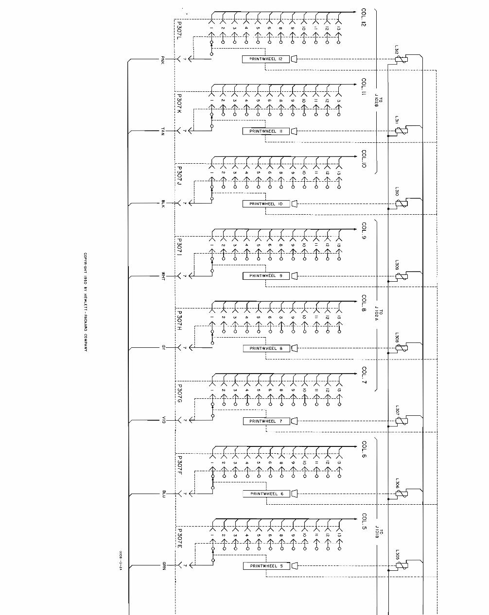
L313(CLUTCHSOLENOID)
NOTES
S302
R306100
(INTERRUPTED DCNOT USED IN 561 B)
C306470
R305~120~~
C305.011JF
(AC NEUTRAL)
GYWHT
(COMMON)
OS 302(RED)
(6.3 VAC)
C30a C309470 Ha20
C307 S303.011JF J IRECORD I
,..;(~C~Lo.!:!U..!.T~CH~C~O!!:N!.!T~Ro.!:!O-=L!....)----l--------l----<l @ill
(DC SUPPLY)(SWITCHED DC)
GY
(1I5VAC)1
S304IPOWER I~ L ...... ....!...(S~W!!.'~T~CH~E:.!:D~II~5.!;VA~C::...)!..- ....J
JIilili!i1i!i
BRN ORN GRN VIO WHT TAN RED- VIO-
(-----J-rl*l*J-ll*JflrI:lrl-----~" I 3 5 7 9 II 13 15 17 /
\ I
" PAWL MAGNETS /\ I\ I\ I\ I
\ i\, ~ COMMUTATOR BRUSHES -------.... i
\ I
\ 19 21 23 25 27 29 31 33 35 :
J 301 \'-- --- --t-'t-i-- -1'-- ../NC NC VIO- GY-
ORN ORN
P305
NC
J 305 --*-7 I 2 3 4 5 6 a 9 10 II 12 13
•PAWLMAGNETS
L301
COL.I
---+--+-------~,
COL. 2COL.3
L303
TO~---------'----+---- J lOlA
13~ 13~ 13~ 13 tr-oI I II I I I
12E-o I 12~ 12 €--o 12~II I I I II I I I
II~I
II~ II~ II tr-oII I I II I I I I
10~I
10~ 10~ 10tr-o,I
I I II
'0I
0I
0 I 09 E-o 9~ 9 €--o I 9~I I I I II I
4-0I
a troa~ <t a~ '" a '" 0I I 0 0 I, ...J I ...J I ...J I ...J
6 €--o w
~w
~W I
6~w
w 6 w 6 w I W:I: :I: :I: _J :I:
I r-- ~ I ~0 r--
~ I r-~I 0
5 E--o f-5 4-<> f- 5 tro f-
5 tro f-Z Z Z Z
, a: I a: I a: I a:I Q.
~Q.
0 Q.
4 €--o Q.
4~ 4 4~I I II I I
34-0€--o 3 tro 3 tro3 ,I , I II I I I
2~ 2 €-a 2 tr-o 2 €-oI I I
I I I
'0'Q 'Q Q
COL. 4
______________ ------- ----- -- - -- --- -~------ ----- - - ---- - --- -- ------T--- - - - -- --------- ----- - - ---,- -- -- --- ------------------- ----r----------- -- ------ - - -------- ------ - ----- - -------- - - ---------------BEAR- T _nm_n ~ CL~TCH ~ --- - BEAR-----II
RED WIRES TO L 301 - L312 iI
7 7 7 7
-------------L~-~?-~~------T-------------L~-~~?~-------~f----------~~-~~?~--------T------·---- ~~~?~-------l
YEL ORN RED BRN
PIN NO. I 2 3 4 5 6 7 a 9 10 II 12 13
SYMBOL 0 2 4 6 a BLANK BRUSH MINUS 9 7 5 3 ICONNECTION SIGN
WIRE COLOR BLK RED YEL BLU GY TAN SEE PNK WHT VIO GRN ORN BRNSCHEMATIC
COMMUTATOR CONNECTOR P 307
RED YEL BLU GY BLK PNK
REFERENCE DESIGNATIONS
B 301C 301-309CR 301OS 301,302F301J 301,305,306L301-313P 305 - 307R 301- 307S 302-304
UNASSI GNED :C 302-304R302-304
I. J301 CONNECTS TO CONTROL CIRCUITSTHRU P301 (NOT SHOWN)
2. rh INDICATES SUPPLY RETURN (FLOATING GROUND)
3. ~ INDICATES FRAME CONNECTION- (POWER-LINE GROUND)
COPYRIGHT 1960 BY HEWLETT-PACKARO COMPANY
oo561-0-IA

Sect. V Page 1
SECTION VTABLE OF REPLACEABLE PARTS
,....-----------------NOT E---------------------,
Standard components have been used in this instrument,
whenever possible. Special components may be obtained
)
from your local Hewlett-Packard representative or from
the factory.
When ordering parts always include:
1. ~ Stock Number.
2. Complete description of part including circuitreference.
3. Model number and serial number of instrument.
4. If part is not listed, give complete description,function and location of part.
Corrections to the Table of Replaceable Parts are listed
on an Instruction Manual Change sheet at the front of this
manual.

Sect. Y Page 2
TABLE OF REPLACEABLE PARTS
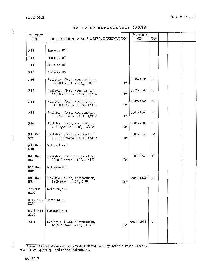
CIRCUIT !fjJ STOCKREF. DESCRIPTION, MFR. • & MFR. DESIGNATION NO. TQ
Bl thru Not assignedB300B301 Part of Printer MechanismC1,2 Capacitor: fixed, paper, 0160-0012 2
.0015 JJi ±1()%, 600 vdcw CC·
C3 Capacitor: fixed, electrolytic, 0180-0042 1120JJi, 350 vdcw CC·
C4 Capacitor: fixed, paper, 0169-0001 1O. 1 Ilf ±10% 1000 vdcw CC·
C5 Capacitor: fixed, ceramic 0150-0012 6.01JJi ±20%, 1000 vdcw CC·
C6 Capacitor: fixed, electrolytic, 0180-0024 1
40 Ilf, 450 vdcw Electromotive Mfg. Co.
C7 Capacitor: fixed, mica, 0140-0037 2390 pf ±5%, 300 vdcw Y·
C8 Capacitor: fixed, ceramic 0150-0024 14.021l f ± 10%, 600 vdcw
Radio Materials Corp.
C9 Same as C7
C10 Capacitor: fixed, electrolytic, 0180-0048 18 Ilf,350 vdcw CC·
Cll Same as C8
C12 Capacitor: fixed, mica, 0140-0010 2820 pf ± 10%, 500 vdcw Y·
C13 thruC20 Not assigned
C21 thruC32 Same as C8
C33 thruC300 Not assigned
C301 Capacitor: fixed, paper, 0160-0101 12 Ilf ± 10%, 600 vdcw CC·
C302 thruC304 Not assigned
C305 Same as C5
• See" LIst of Manufacturers Code Letters For Replaceable Parts Table" .TQ - Total quantity used in the instrument.
Model 561B
00165-3

)
)
Model 561B
TABLE OF REPLACEABLE PARTS
CIRCUIT ~ STOCKREF. DESCRIPTION, MFR. • & MFR. DESIGNATION NO. TQ
C306 Capacitor: fixed, mica, 0140-0027 2470 pf ± 10%, 500 vdcw V*
C307 Same as C5
C308 Same as C306
C309 Same as C12
CR1 thru Rectifier, silicon: 400V PlY, 500 rna BV* 1901-0028 5CR5
DS1 thru Not assignedDS300
DS301,302 Lamp, 6V, GE #12 0* 2140-0012 2
F1 Fuse, cartridge: for 115V operation: 2110-0021 11. 25 amp, 125V, slow blow E*
for 230V operation:.6 amp, 250V, slow blow 2110~016
F2 Fuse, cartridge: 1/4 amp, 250V T* 2110-0004 1
F3 Fuse: #30 gauge copper wire 1
F4 thru Not assignedF300
F301 Fuse, cartridge: slow blow, .6 amp 125V T* 2110-0016 1
J1 thru Not assignedJ100
J101, 102 Connector, female: 50 pin miniature HH* 1251-0101 4
J103 Connector, female: 8 pin H* 1251-0043 1
J104 thru Not assignedJ300
J301 Connector, female: 36 pin HH* 1251-0085 1
J302 thru Not assignedJ304
J305, 306 Connector, female: 13 pin 1251-0098 1Continental Connector Co.
K1 Relay: SPDT CT* 0490-0010 1
L1 thru Not assignedL300
L301 thru Part of Printer Mechanism 9161~008 12L312
• See" LIst of Manufacturers Code Letters For Replaceable Parts Table" •TQ - Total quantity used in the instrument.
00165-3
Sect. V Page 3

Sect. V Page 4
TABLE OF REPLACEABLE PARTS
CIRCUIT <FjJ STOCKREF. DESCRIPTION, MFR. * &MFR. DESIGNATION NO. TQ
L313 Part of Printer Mechanism 0491-0004 1
Model 561B
PI Power cable, with NEMA plug
P2 thru Not assignedP102
P103 Connector, male: 8 pin
P104 thru Not assignedP300
P301 Connector, male: 36 pin
P302 thru Not assignedP304
Elec. Cords Co. 8120-0015 1
H* 1251-0133 1
HH* 1251-0084 1
P305,306 Connector, male: 13 pin, printed circuit
P307 Same as J305, 306
HP* 561B-65A 2
R1
R2
R3
R4
R5
R6
R7
R8
R9
RIO
R11
Resistor: fixed, composition,100,000 ohms ± 10%, 1 W
Resistor: fixed, composition,22,000 ohms ± 10%, 2 W
Resistor: fixed, composition,22,000 ohms ± 10%, 1/2 W
Resistor: fixed, composition,15,000 ohms ± 10%, 1/2 W
Resistor: fixed, composition,10 megohms ± 10%, 1/2 W
Resistor: fixed, composition,47,000 ohms ± 5%, 1/2 W
Resistor: fixed, composition,100 ohms ± 10%, 1/2 W
Resistor: fixed, composition,1. 8 megohms ± 10%, 1/2 W
Resistor: fixed, composition,1 megohm ± 10%, 1/2 W
Resistor: fixed, composition,15,000 ohms ± 10%, 1 W
Resistor: fixed, composition,22,000 ohms ± 10%, 1 W
0690-1041 1B*
0693-2231 1B*
0687 -2231 13B*
0687-1531 1B*
0687 -1061 2B*
0686-4735 2B*
0687-1011 2B*
0687-1851 1B*
0687 -1051 1B*
0690-1531 2B*
0690-2231 1B*
* See" LIst of Manufacturers Code Letters For Replaceable Parts Table" .TQ J Total quantity used in the instrument.
00165-3
)
)
Model 561B
TABLE OF REPLACEABLE PARTS
CIRCUIT ~ STOCKREF. DESCRIPTION, MFR. • & MFR. DESIGNATION NO. TQ
R12 Same as R10
R13 Same as R7
R14 Same as R6
R15 Same as R5
R16 Resistor: fixed, composition, 0690-1031 110,000 ohms ±10%,lW B*
R17 Resistor: fixed, composition, 0687 -3341 1330,000 ohms ±10%, 1/2 W B*
R18 Resistor: fixed, composition, 0687-1241 1120,000 ohms ± 10%, 1/2 W B*
R19 Resistor: fixed, composition, 0687-1041 1100,000 ohms ± 10%, 1/2 W B*
R20 Resistor: fixed, composition, 0687-2261 122 megohms ± 10%, 1/2 W B*
R21 thru Resistor: fixed, composition, 0687-2741 12R32 270,000 ohms ± 10%, 1/2 W B*
R33 thru Not assignedR40
R41 thru Resistor: fixed, composition, 0687-8231 11R52 82,000 ohms ± 10%, 1/2 W B*
R53 thru Not assignedR60
R61 thru Resistor: fixed, composition, 0690-1821 11R72 1800 ohms ±10%, 1 W B*
R73 thru Not assignedR100
R101 thru Same as R3R112
R113 thru Not assignedR300
R301 Resistor: fixed, composition, 0690-1031 110,000 ohms ±10%, 1 W B*
* See" List of Manufacturers Code Letters For Replaceable Parts Table" .TQ - Total quantity used in the instrument.
00165-3
Sect. V Page 5

Sect. V Page 6
TABLE OF REPLACEABLE PARTS
CIRCUIT If}! STOCKREF. DESCRIPTION, MFR. • & MFR. DESIGNATION NO. TQ
R302 thru Not assignedR304
R305 Resistor: fixed, composition, 0687 -1211 1120 ohms ± 10%, 1/2 W B*
R306 Resistor: fixed, composition, 0690-1011 1100 ohms ±10%, 1 W B*
R307 Resistor: fixed, composition, 0690-3301 133 ohms ±10%, lW B*
S101 Switch, Slide, DPDT 3101-0011 1S102 thru Not assignedS300
S301 Switch, Slide, 4 pole, double throw AT* 3101-0034 1S302 Switch, SPDT, cam-operated, 3101-0013 1
make-before-break KK·
S303 Switch, toggle CR* 3101-0015 1
S304 Switch, toggle: SPST, 125V, 15 amp CR* ~101-0030 1
T1 Transformer, power HP* 9100-0111 1
VI thru Tube,electron: 5965 zz* 1932-0009 7V7
V8 Tube, electron: 2D21 ZZ* 1941-0005 1
V9 Lamp, neon: type NE2 0* 2140-0008 1
NOTICE
REFER TO PRINTER MECHANISM MANUAL FORPARTS LOCATED ON PRINTER MECHANISM
Accessories:
Model 561B
Paper tape, folded
Inked ribbon
Service kit -with type cleaner, moly oil,light machine oil, instructions
Cable: 100-conductor, 6 ft. long, connects 561Bwith -hp- equipment providing 10-line code.
Connector: 100 pin, mates with J101 or J102 onrear of chassis (same as connectors on561B-16A cable)
Digital Recorder Kits for operating 561B fromthe following electronic counters:
Models 521D, 521E
Model 523C
Model 524C
9281-0018 1
9283-0002 1
560A-95N
561B-16A
561B-95D
521D-95B
523C-95B
524C-95B
• See" List of Manufacturers Code Letters For Replaceable Parts Table" •TQ - Total quantity used in the instrument.
00165-3

Model 561B Sect. V Page 7
LIST OF MANUFACTURERS CODES
CODE CODELETTER MANUFACTURER ADDRESS LETTER MANUFACTURER ADDRESS
A Aerovox Corp. New Bedford, Moss. AK Hammerlund Mfg. Co., Inc. New York I, N. Y.B Allen.Brodley Co. Milwaukee 4, Wis. AL Industrial Condenser Corp. Chicago 18, III.C Amperite Co. New York, N. Y. AM Insuline Corp. of America Manchester, N. H.D Arrow, Hart & Hegemon Hartford, Conn. AN Jennings Radio Mfg. Corp. Son Jose, Calif.E Bussman Manufacturing Co. St. Louis, Mo. AO E. F. Johnson Co. Waseca, Minn.
F Carborundum Co. Niagara Falls, N. Y. AP Lenz Electric Mfg. Co. Chicago 47, III.G Centro lob Milwaukee I, Wis. AQ Micro·Switch Freeport, III.H Cinch-Jones Mfg. Co. Chicago 24, III. AR Mechanical Industries Prod. Co. Akron 8, OhioHP Hewlett·Packard Co. Polo Alto, Calif. AS Model Eng. & Mfg., Inc. Huntington, Ind.I Clarostat Mfg. Co. Dover, N. H. AT The Muter Co. Chicago 5, III.J Cornell Dubilier Elec. Co. South Plainfield, N. J. AU Ohmite Mfg. Co. Skokie, III.K Hi-Q Division of Aerovox Olean, N. Y. AV Resistance Products Co. Harrisburg, Po.L Erie Resistor Corp. Erie b, Po. AW Radio Condenser Co. Camden 3, N. J.M Fed. Telephone & Radio Corp. Clifton, N. J. AX Shallcross Manufacturing Co. Collingdale, Po.N General Electric Co. Schenectady 5, N. Y. AY Solar Manufacturing Co. Los Angeles 58, Calif.0 General Electric Supply Corp. Son Francisco, Calif. AZ Sealectro Corp. New Rochelle, N. Y.P Girard.Hopkins Oakland, Calif. BA Spencer Thermostat Attleboro, Moss.Q Industrial Products Co. Danbury, Conn. BC Stevens Manufacturing Co. Mansfield, OhioR International Resistance Co. Philadelphia 8, Po. BD Torrington Manufacturing Co. Von Nuys, Calif.S Lectrohm Inc. Chicago 20, III. BE Vector Electronic Co. Los Angeles b5, Calif.T Littlefuse Inc. Des Plaines, III. BF Weston Electrical Inst. Corp. Newark 5, N. J.U Maguire Industries Inc. Greenwich, Conn. BG Advance Electric & Relay Co. Burbank, Calif.V Micamold Radio Corp. Brooklyn 37, N. Y. BH E. I. DuPont Son Francisco, Calif.W Oak Manufacturing Co. Chicago 10, III. BI Electronics Tube Corp. Philadelphia 18, Po.X P. R. Mallory Co., Inc. Indianapolis, Ind. BJ Aircraft Radio Corp. Boonton, N. J.Y Radio Corp. of America Harrison, N. J. BK Allied Control Co., Inc. New York 21, N. Y.Z Sangamo Electric Co. Marion, III. BL Augat Brothers, Inc. Attleboro, Moss.
) AA Sarkes Tonion Bloomington, Ind. BM Corter Radio Division Chicago, III.BB Signal Indicator Co. Brooklyn 37, N. Y. BN CBS Hytron Radio & Electric Danvers, Mass.
CC Sprag ue Electric Co. North Adams, Moss. BO Chicago Telephone Supply Elkhart, Ind.DD Stackpole Corban Co. St. Marys, Pa. BP Henry L. Crowley Co., Inc. West Orange, N. J.EE Sylvania Electric Products Co. Warren, Po. BQ Curtiss.Wright Corp. Carlstadt, N. J.FF Western Electric Co. New York 5, N. Y. BR Allen B. DuMont Lobs Clifton, N. J.GG Wilkor Products, Inc. Cleveland, Ohio BS Excel Transformer Co. Oakland, Calif.HH Amphenol Chicago 50, III. BT General Radio Co. Cambridge 39, Moss.II Dial Light Co. of America Brooklyn 37, N. Y. BU Hughes Aircraft Co. Culver City, Calif.JJ Leecraft Manufacturing Co. New York, N. Y. BV International Rectifier Corp. EI Segundo, Calif.KK Switchcraft, Inc. Chicago 22, III. BW James Knights Co. Sandwich, III.LL Gremar Manufacturing Co. Wakefield, Moss. BX Mueller Electric Co. Cleveland, OhioMM Carad Corp. Redwood City, Calif. BY Precision Thermometer & Inst. Co. Philadelphia 30, Po.NN Electro Manufacturing Co. Kansas City, Mo. BZ Radio Essentials Inc. Mt. Vernon, N. Y.00 Acro Manufacturing Co. Columbus Ib, Ohio CA Raytheon Manufacturing Co. Newton, Moss.PP Alliance Manufacturing Co. Alliance, Ohio CB Tung-Sol Lamp Works, Inc. Newark 4, N. J.QQ Arco Electronics, Inc. New York 13, N. Y. CD Varian Associates Polo Alto, Calif.RR Astron Corp. East Newark, N. J. CE Victory Engineering Corp. Union, N. J.SS Axel Brothers Inc. Long Island City, N. Y. CF Weckesser Co. Chicago 30, III.TT Belden Manufacturing Co. Chicago 44, III. CG Wilco Corporation Indianapolis, Ind.UU Bird Electronics Corp. Cleveland 14, Ohio CH Winchester Electronics, Inc. Santo Monico, Calif.VV Barber Colman Co. Rockford, III. CI Malco Tool & Die Los Angeles 42, Calif.WW Bud Radio Inc. Cleveland 3, Ohio CJ Oxford Electric Corp. Chicago 15, III.
XX Allen D. Cardwell Mfg. Co. Plainville, Conn. CK Camloc-Fastener Corp. Paramus, N. J.YY Cinema Engineering Co. Burbank, Calif. CL George K. Garrett Philadelphia 34, Po.
ZZ Any brand tube meeting CM Union Switch & Signal Swissvale, Po.
RETMA standards. CN Radio Receptor New York II, N. Y.
AB Corning Gloss Works Corning, N. Y. CO Automatic & Precision Mfg. Co. Yonkers, N. Y.
AC Dole Products, Inc. Columbus, Neb. CP Bassick Co. Bridgeport 2, Conn.
AD The Droke Mfg. Co. Chicago 22, III. CQ Birnbach Radio Co. New York 13, N. Y.
AE Elco Corp. Philadelphia 24, Po. CR Fischer Specialties Cincinnati b, Ohio
AF Hugh H. Eby Co. Philadelphia 44, Po. CS Telefunken (c/o MVM, Inc.) New York, N. Y.) AG Thomas A. Edison, Inc. West Orange, N. J. CT Potter·Brumfield Co. Princeton, Ind.
AH Fansteel Metallurgical Corp. North Chicago, III. CU Connon Electric Co. Los Angeles, Calif.
AI General Ceramics & Steatite Corp. Keasbey, N. J. CV Dynac, Inc. Polo Alto, Calif.
AJ The Gudeman Co. Sunnyvale, Calif. CW Good-All Electric Mfg. Co. Ogallala, Nebr.
00165-2

Appendix I
APPENDIX I - MANUAL CHANGES
This manual applies directly to ~ Model 561B/BR Digital Recorders with serialnumber prefix 334. This manual with the following cha~es also applies to olderRecorders with serial prefix unber 241 or 038. To adapt this manual to theseolder Recorders, make changes as follows:
Model 561B
Serial Number Prefix
241038
Make Change
12
CHANGE 1:(241)
Section IV, Page 5, Figure 4-4 (Control Circuits),Revise diagram as shown in Figure 1 below.
Section V, Page 6, Table of Replaceable Parts,Change S301 to read:
"S301, Switch, toggle, DPDT, ~ Stock No. 3101-0033".
T1
0--0230V
.....__+- ..... {4}-_-J
PART OF P301
1 34 ---35- 36
1I~ - ---- ----I 5304 I
I ~ II []E]
I
I
I IL J
PART Of PRINTER NECH.
PART OF J301
IA-O
Figure 1. Changes for prefix 241
00165-3

Model 561B
CHANGE 2:(038)
Section IV, Page 5, Figure 4-4,(Control Circuits),Revise diagram as shown in Figure 2 below.
Section V, Page 6, Table of Replaceable Parts,Delete S301.
T1
Appendix I
)
I 34 - - - 35 -- 36
1I~ - ---- ----I 5304 I
I ~ II []E]
I
I
I IL J
PART Of PRINTER IIECH.
PART OF P301
PART OF J301
)
00165-3
Figure 2. Changes for prefix 038
IA-l

ELECTRONIC INSTRUMENTATION SALES AND SERVICEUNITED STATES, CANADA, CENTRAL AND SOUTH AMERICA~
UNITED STATESALABAMAP.O. Box 42072003 Byrd Spring Road S.W.Huntsville 35802TWX: 510-579·2204Tel: (205) ~81-4591
ARIZONA3009 North Scottsdale RoadScottsdale 85251Tel: (602) 945-7601TWX: 910-950·1282
232 South Tucson BoulevardTucson 85716Tel: (602) 623·2564TWX: 910·952-1162
CALIFORNIA3939 Lankershim BoulevardNorth Hollywood 91604Tel: (213) 877·1282TWX: 910-499-2170
1101 Embarcadero RoadPalo Alto 94303Tel: (415) 327·6500TWX: 910-373·1280
2591 Carlsbad AvenueSacramento 95821Tel: (916) 482·1463TWX: 910·367·2092
1055 Shafter StreetSan Diego 92106Tel: (714) 223·8103TWX: 910·335·2000
COLORADO7965 East PrenticeEnglewood 80110Tel: (303) 771-3455TWX: 910·935·0705
CONNECTICUT508 Tolland StreetEast Hartford 06108Tel: (203) 289·9394TWX 710·425·3416
111 East AvenueNorwalk 06851Tel: (203) 853·1251TWX: 710-468-3750
DELAWARE3941 Kennett PikeWilmington 19807Tel: (302) 655·6161TWX: 510·666·2214
FLORIDASuite 1069999 N.E. 2nd AvenueMiami Shores 33138Tel: (305) 758·3626TWX: 810·848·7262
P.O. Box 20007Herndon Station 32814621 Commonwealth AvenueOrlandoTel: (305) 841-3970TWX: 810·850·0113
P.O. Box 8128Madeira Beach 33708410 150th AvenueSI. PetersburgTel: (813) 391·0211TWX: 810·863-0366
GEORGIA3110 Maple Drive N.E.Atlanta 30305Tel: (404) 233-1141TWX: 810-751-3283
ILLINOIS5500 Howard StreetSkokie 60076Tel: (312) 677-0400TWX: 910·223·3613
INDIANA4002 Meadows DriveIndianapolis 46205Tel: (317) 546-4891TWX: 810-341·3263
LOUISIANAP.O. Box 8561942 Williams 80ulevardKenner 70062Tel: (504) 721·6201TWX: 810-955·5524
MARYLAND6707 Whitestone RoadBaltimore 21207Tel: (301) 944-5400TWX: 710·862-0850
P.O. Box 727Twinbrook Station 2085112303 Twinbrook ParkwayRockvilleTel: (301) 427-7560TWX: 710·828·9684
MASSACHUSETTSMiddlesex TurnpikeBurlington 01803Tel: (617) 272-9000TWX: 71 0·332·0382
MICHIGAN24315 Northwestern HighwaySouthfield 48076Tel: (313) 353·9100TWX: 810·232·1532
MINNESOTA2459 University AvenueSt. Paul 55114Tel: (612) 646·7881TWX: 910·563·3734
MISSOURI9208 Wyoming PlaceKansas City 64114Tel: (816) 333·2445TWX: 910·771·2087
2812 South Brentwood Blvd.SI. Louis 63144Tel: (314) 644-0220TWX: 910·760·1670
NEW JERSEYCrystal Brook Prof. Bldg.Route 35EatontownTel: (201) 747-1060
391 Grand AvenueEnglewood 07631Tel: (201) 567·3933TWX: 710·991·9707
NEW MEXICOP.O. Box 8366Station C 871086501 Lomas Boulevard N.E.AlbuquerqueTel: (505) 255-5586TWX: 910·989·1665
156 Wyatt DriveLas Cruces 88001Tel: (505) 526-2486TWX: 910·983·0550
NEW YORK1219 Campville RoadEndicott 13760Tel: (607) 754-0050TWX: 510-252·0890
236 East 75th StreetNew York 10021Tel: (212) 879·2023TWX: 710·581·4376
82 Washington StreetPoughkeepsie 12601Tel: (914) 454-7330TWX: 510·248·0012
39 Saginaw DriveRochester 14623Tel: (716) 473·9500TWX: 510·253-5981
1025 Northern BoulevardRoslyn, Long Island 11576Tel: (516) 869·8400TWX: 510·223·0811
5858 East Molloy RoadSyracuse 13211Tel: (315) 454·2486TWX: 710·541-0482
NORTH CAROLINAP.O. Box 51871923 North Main StreetHigh Point 27262Tel: (919) 882-6873TWX: 510·926-1516
OHIO5579 Pearl RoadCleveland 44129Tel: (216) 884-9209TWX: 810·421·8500
1250 West Dorothy LaneDayton 45409Tel: (513) 298·0351TWX: 810·459·1925
OREGON2737 S.W. Corbett AvenuePorlland 97201Tel: (503) 228·5107
PENNSYLVANIAPark Place Office BuildingCamp HillTel: (717) 737·6791
Monroe ComplexMoss Side BoulevardMonroeville 15146Tel: (412) 271-0724TWX: 710-797·3650
144 Elizabeth StreetWest Conshohocken 19428Tel: (215) 248·1600, 828·6200TWX: 510-660·8715
TEXASP.O. Box 71663605 Inwood RoadDallas 75209Tel: (214) 357-1881TWX: 910-861·4081
P.O. Box 228134242 Richmond AvenueHouston 77027Tel: (713) 667-2407TWX: 910·881-2645
GOVERNMENT CONTRACT OFFICE225 Billy Mitchell RoadSan Antonio 78226Tel: (512) 434·4171TWX: 910·871·1170
UTAH2890 South Main StreetSalt Lake City 84115Tel: (801) 486-8166TWX: 910·925·5681
VIRGINIAP.O. Box 65142111 Spencer RoadRichmond 23230Tel: (703) 282-5451TWX: 710·956-0157
WASHINGTON11656 N.E. Eighth StreetBellevue 98004Tel: (206) 454·3971TWX: 910·443·2303
FOR AREAS NOTLISTED, CONTACT:Hewlett·Packard1501 Page Mill RoadPalo Alto, California 94304Tel: (415) 326-7000TWX: 910·373-1267Telex: 34·8461
CANADABRITISH COLUMBIAHewlett·Packard (Canada) Ltd.2184 West 8roadwayVancouverTel: (604) 738·7520TWX: 610·922-5050
ONTARIOHewlett·Packard (Canada) Ltd.880 Lady Ellen PlaceOttawa 3Tel: (613) 722·4223TWX: 610·562-1952
Hewlett·Packard (Canada) Ltd.1415 Lawrence Avenue WestTorontoTel: (416) 249·9196TWX: 610·492·2382
QUEBECHewlett-Packard (Canada) Ltd.275 Hymus BoulevardPointe ClaireTel: (514) 697·4232TWX: 610·422-3022Telex: 01·2819
FOR AREAS NOTLISTED, CONTACT:Hewlett-Packard Inter·Americas1501 Page Mill RoadPalo Alto, California 94304Tel: (415) 326·7000TWX: 910·373·1267Telex: 034-8461Cable: HEWPACK Palo Alto
CENTRAL AND SOUTH AMERICAARGENTINAMauricio A. SuMezTelecomunicacionesCarlos Calvo 224Buenos AiresTel: 30·6312, 34·9087
BRAZILCiental, Importacao e
Com~rcio Ltda.Rua Cleto Campelo, 44 - 5· andarRecife
Ciental, Importacao eCom~rcio Ltda.
Avenida 13 de Maio, 13·22· andarRio de Janeiro, G.8.
Ciental, Importacao eCom~rcio Ltda.
Rua Des. Eliseu Guilherme, 62Sao Paulo 8Tel: 70·2318
CHILEH~ctor CalcagniCasilla 13942SantiagoTel: 490.505, 393.119
COSTA RICALie. Alfredo Gallegos GurdianApartado 3243San JoseTel: 21·86,13
EL SALVADORElectr6nicaApartado Postal 1589San SalvadorTel: 4683
GUATEMALAOlander Associates Latin AmericaApartado 12267a. Calle, 0-22, Zona 1Guatemala CityTel: 22812
MEXICOHewlett·Packard Mexicana,
SA de C.V.Eugenia 408. Dept. 1Mexico 12, D.F.
NICARAGUARoberto Teran G.Edificio TeranApartado Postal 689ManaguaTel: 3451, 3452
PANAMAElectr6nico Balboa, SAP.O. Box 4929Panama CityTel: 3·0833
PERUFernando Ezeta B.Av. Petit Thouars 4719Casilla 3061LimaTel: 50346
PUERTO RICOSan Juan Electronics, Inc.Ponce de Le6n No. 150, Stop 3Pta. de Tierra Sta.San JuanTel: (809) 725·3342
VENEZUELACilec, C.A.Edif. Arisan·Of. it4Avda. Francisco de MirandaApartado del Este 10934 ChacaitoCaracasTel: 71.88.05
FOR AREAS NOTLISTED, CONTACT:Hewlett·Packard Inter·Americas1501 Page Mill RoadPalo Alto, California 94304Tel: (415) 326·7000TWX: 910·373-1267Telex: 034-8461Cable: HEWPACK Palo Alto
12/66

00561-9002
HEWLETT. PACKARD
PRINTED IN U.S.A.