hp 1820 switch series - loginnbc.intersmart.com.br/pdf/hpn_1820_manual.pdf · hp 1820 switch series...
TRANSCRIPT

HP 1820 Switch Series Installation and Getting Started Guide
HP 1820-8G Switch (J9979A)HP 1820-24G Switch (J9980A)HP 1820-48G Switch (J9981A)HP 1820-8G-PoE+ (65W) Switch (J9982A)HP 1820-24G-PoE+ (185W) Switch (J9983A)HP 1820-48G-PoE+ (370W) Switch (J9984A)
Power over Ethernet


HP 1820 Switch Series
Installation and Getting Started Guide

© Copyright 2015 Hewlett-Packard Development Company, L.P.
The information contained herein is subject to change without notice.
This document contains proprietary information, which is protected by copyright. No part of this document may be photocopied, reproduced, or translated into another language without prior written consent of Hewlett-Packard.
Manual Part Number5998-5835February 2015
Applicable ProductsHP 1820-8G Switch (J9979A)HP 1820-24G Switch (J9980A)HP 1820-48G Switch (J9981A)HP 1820-8G-PoE+ (65W) Switch (J9982A)HP 1820-24G-PoE+ (185W) Switch (J9983A)HP 1820-48G-PoE+ (370W) Switch (J9984A)
SafetyBefore installing and operating this product, please read the “Installation Precautions” in Chapter 2, “Installing the Switch”, and the safety statements in General Safety and Regulatory Information booklet included with the product.
DisclaimerHEWLETT-PACKARD COMPANY MAKES NO WARRANTY OF ANY KIND WITH REGARD TO THIS MATERIAL, INCLUDING, BUT NOT LIMITED TO, THE IMPLIED WARRANTIES OF MERCHANTABILITY AND FITNESS FOR A PARTICULAR PURPOSE. Hewlett-Packard shall not be liable for errors contained herein or for incidental or consequential damages in connection with the furnishing, performance, or use of this material.
The only warranties for HP products and services are set forth in the express warranty statements accompanying such products and services. Nothing herein should be construed as constituting an additional warranty. HP shall not be liable for technical or editorial errors or omissions contained herein.
Hewlett-Packard assumes no responsibility for the use or reliability of its software on equipment that is not furnished by Hewlett-Packard.
WarrantyFor the latest license and warranty information, visit www.hp.com/networking/support.
A copy of the specific warranty terms applicable to your Hewlett-Packard products and replacement parts can be obtained from your HP Sales and Service Office or authorized dealer.

5
Contents
1 Switch Overview
Switch Hardware Features . . . . . . . . . . . . . . . . . . . . . . . . . . . . . . . . . . . . . . . 1-2
Network Ports . . . . . . . . . . . . . . . . . . . . . . . . . . . . . . . . . . . . . . . . . . . . . . 1-4
LEDs . . . . . . . . . . . . . . . . . . . . . . . . . . . . . . . . . . . . . . . . . . . . . . . . . . . . . . 1-5
Mode Button . . . . . . . . . . . . . . . . . . . . . . . . . . . . . . . . . . . . . . . . . . . . . . . 1-6
Reset Button . . . . . . . . . . . . . . . . . . . . . . . . . . . . . . . . . . . . . . . . . . . . . . . 1-6
Power Connector . . . . . . . . . . . . . . . . . . . . . . . . . . . . . . . . . . . . . . . . . . . 1-6
Switch Features . . . . . . . . . . . . . . . . . . . . . . . . . . . . . . . . . . . . . . . . . . . . . . . . 1-7
2 Installing the Switch
Included Parts . . . . . . . . . . . . . . . . . . . . . . . . . . . . . . . . . . . . . . . . . . . . . . . . . 2-1
Installation Precautions . . . . . . . . . . . . . . . . . . . . . . . . . . . . . . . . . . . . . . 2-4
Installation Procedure . . . . . . . . . . . . . . . . . . . . . . . . . . . . . . . . . . . . . . . . . . . 2-5
1. Prepare the Installation Site . . . . . . . . . . . . . . . . . . . . . . . . . . . . . . . . 2-6
2. Verify the Switch Passes Self Test . . . . . . . . . . . . . . . . . . . . . . . . . . . 2-6
3. Mount the Switch . . . . . . . . . . . . . . . . . . . . . . . . . . . . . . . . . . . . . . . . . 2-9
4. Connect the Switch to a Power Source . . . . . . . . . . . . . . . . . . . . . . 2-13
5. Connect the Network Cables . . . . . . . . . . . . . . . . . . . . . . . . . . . . . . . 2-14
6. Installing or Removing SFPs . . . . . . . . . . . . . . . . . . . . . . . . . . . . . . . 2-15
3 Configuring the Switch
Initial Configuration . . . . . . . . . . . . . . . . . . . . . . . . . . . . . . . . . . . . . . . . . . . . . 3-1
Using the 192.168.1.1 IP Address . . . . . . . . . . . . . . . . . . . . . . . . . . . . . . . . . . 3-3
Where to Go From Here . . . . . . . . . . . . . . . . . . . . . . . . . . . . . . . . . . . . . . . . . 3-4
4 Troubleshooting
Basic Troubleshooting Tips . . . . . . . . . . . . . . . . . . . . . . . . . . . . . . . . . . . . . . 4-1
Diagnosing with the LEDs . . . . . . . . . . . . . . . . . . . . . . . . . . . . . . . . . . . . . . . . 4-2
LED patterns for General Switch Troubleshooting . . . . . . . . . . . . . . . 4-2
6
Diagnostic Tips: . . . . . . . . . . . . . . . . . . . . . . . . . . . . . . . . . . . . . . . . . . . . . 4-3
LED Patterns for PoE Troubleshooting . . . . . . . . . . . . . . . . . . . . . . . . . 4-4
Testing the Switch by Resetting It . . . . . . . . . . . . . . . . . . . . . . . . . . . . . . . . . 4-5
Restoring to Factory Defaults . . . . . . . . . . . . . . . . . . . . . . . . . . . . . . . . . . . . . 4-5
HP Customer Support Services . . . . . . . . . . . . . . . . . . . . . . . . . . . . . . . . . . . 4-6
Before Calling Support . . . . . . . . . . . . . . . . . . . . . . . . . . . . . . . . . . . . . . . 4-6
A Specifications
Switch Specifications . . . . . . . . . . . . . . . . . . . . . . . . . . . . . . . . . . . . . . . . . . . A-1
Physical . . . . . . . . . . . . . . . . . . . . . . . . . . . . . . . . . . . . . . . . . . . . . . . . . . . A-1
Electrical . . . . . . . . . . . . . . . . . . . . . . . . . . . . . . . . . . . . . . . . . . . . . . . . . A-1
Environmental . . . . . . . . . . . . . . . . . . . . . . . . . . . . . . . . . . . . . . . . . . . . . A-2
Acoustics . . . . . . . . . . . . . . . . . . . . . . . . . . . . . . . . . . . . . . . . . . . . . . . . . A-2
Safety . . . . . . . . . . . . . . . . . . . . . . . . . . . . . . . . . . . . . . . . . . . . . . . . . . . . A-2
Standards . . . . . . . . . . . . . . . . . . . . . . . . . . . . . . . . . . . . . . . . . . . . . . . . . . . . . A-3
Cabling and Technology Information Specifications . . . . . . . . . . . . . . . . A-4
Technology Distance Specifications . . . . . . . . . . . . . . . . . . . . . . . . . . . A-5
Mode Conditioning Patch Cord . . . . . . . . . . . . . . . . . . . . . . . . . . . . . . . . . . A-5
Installing the Patch Cord . . . . . . . . . . . . . . . . . . . . . . . . . . . . . . . . . . . . A-6
Twisted-Pair Cable/Connector Pin-Outs . . . . . . . . . . . . . . . . . . . . . . . . . . . A-7
Straight-through Twisted-Pair Cable for10 Mbps or 100 Mbps Network Connections . . . . . . . . . . . . . . . . . . . . A-9
Crossover Twisted-Pair Cable for10 Mbps or 100 Mbps Network Connection . . . . . . . . . . . . . . . . . . . . A-10
Straight-Through Twisted-Pair Cable for1000 Mbps Network Connections . . . . . . . . . . . . . . . . . . . . . . . . . . . . A-11
B EMC Regulatory Statements
Regulatory Statements . . . . . . . . . . . . . . . . . . . . . . . . . . . . . . . . . . . . . . . . . . B-1
Index

1-1
1
Switch Overview
The HP 1820 Switch Series are multiport switches that can be used to build high-performance switched workgroup networks. These switches are store-and-forward devices that offer low latency for high-speed networking. Three of the switches also support the IEEE 802.3at standard for providing PoE+ power to connected devices.
Throughout this manual, these switches will be referred to as the 1820-8G Switch, 1820-24G Switch, 1820-48G Switch, 1820-8G-PoE+ Switch, 1820-24G-PoE+ Switch, and the 1820-48G-PoE+ Switch.
■ The 1820-8G Switch has 8 auto-sensing 10/100/1000BASE-T RJ-45 ports. Port 1 is a Power over Ethernet Powered Device (PoE PD) port. The switch can be powered by a network connection to port 1 from PoE power sourcing equipment (PSE), such as a PoE switch.
■ The 1820-24G Switch has 24 auto-sensing 10/100/1000BASE-T RJ-45 ports and two SFP slots for supported HP SFP fiber-optic transceivers (ports 25 and 26).
■ The 1820-48G Switch has 48 auto-sensing 10/100/1000BASE-T RJ-45 ports and four SFP slots for supported HP SFP fiber-optic transceivers (ports 49 to 52).
■ The 1820-8G-PoE+ Switch has 8 auto-sensing 10/100/1000BASE-T RJ-45 ports. The switch supports the IEEE 802.3at standard and is capable of providing 65 watts of PoE power through ports 1-4.
■ The 1820-24G-PoE+ Switch has 24 auto-sensing 10/100/1000BASE-T RJ-45 ports and two SFP slots for supported HP SFP fiber-optic transceivers (ports 25 and 26). The switch supports the IEEE 802.3at standard and is capable of providing 185 watts of PoE power through ports 1-12.
■ The 1820-48G-PoE+ Switch has 48 auto-sensing 10/100/1000BASE-T RJ-45 ports and four SFP slots for supported HP SFP fiber-optic transceivers (ports 49 to 52). The switch supports the IEEE 802.3at standard and is capable of providing 370 watts of PoE power through ports 1-24.
These switches can be directly connected to computers, printers, and servers to provide dedicated bandwidth to those devices, and you can build a switched network infrastructure by connecting the switch to hubs, other switches, or routers. In addition, these switches offer network management capabilities.
1-2
Switch OverviewSwitch Hardware Features
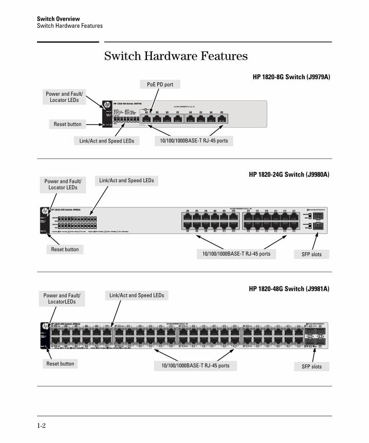
Switch Hardware Features
HP 1820-8G Switch (J9979A)
Power and Fault/Locator LEDs
10/100/1000BASE-T RJ-45 ports
Reset button
Link/Act and Speed LEDs
PoE PD port
HP 1820-24G Switch (J9980A)Power and Fault/
Locator LEDsLink/Act and Speed LEDs
10/100/1000BASE-T RJ-45 portsReset button
SFP slots
HP 1820-48G Switch (J9981A)Power and Fault/
LocatorLEDsLink/Act and Speed LEDs
10/100/1000BASE-T RJ-45 ports Reset button SFP slots

1-3
Switch OverviewSwitch Hardware Features
HP 1820-8G-PoE+ (65W) Switch (J9982A)
Link/Act and Mode LEDs
10/100/1000BASE-T RJ-45 ports
Power and Fault/Locator LEDs
Mode button
Reset button
PoE+ ports 1-4
HP 1820-24G-PoE+ (185W) Switch (J9983A)
Link/Act and Mode LEDs
10/100/1000BASE-T RJ-45 ports SFP slots
Power and Fault/ Locator LEDs
Reset button Mode button
PoE+ ports 1-12
HP 1820-48G-PoE+ (370W) Switch (J9984A)
Link/Act and Mode LEDs
10/100/1000BASE-T RJ-45 ports SFP slots
Power and Fault/ Locator LEDs
Reset button Mode button
PoE+ ports 1-24
1-4
Switch OverviewSwitch Hardware Features
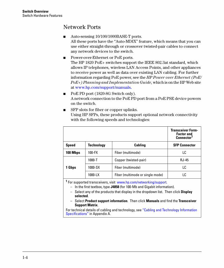
Network Ports
■ Auto-sensing 10/100/1000BASE-T ports.All these ports have the “Auto-MDIX” feature, which means that you can use either straight-through or crossover twisted-pair cables to connect any network devices to the switch.
■ Power-over-Ethernet or PoE ports.The HP 1820 PoE+ switches support the IEEE 802.3at standard, which allows IP telephones, wireless LAN Access Points, and other appliances to receive power as well as data over existing LAN cabling. For further information regarding PoE power, see the HP Power over Ethernet (PoE/
PoE+) Planning and Implementation Guide, which is on the HP Web site at www.hp.com/support/manuals.
■ PoE PD port (1820-8G Switch only).A network connection to the PoE PD port from a PoE PSE device powers on the switch.
■ SFP slots for fiber or copper uplinks. Using HP SFPs, these products support optional network connectivity with the following speeds and technologies:
Transceiver Form-Factor and Connector1
Speed Technology Cabling SFP Connector
100 Mbps 100-FX Fiber (multimode) LC
1 Gbps
1000-T Copper (twisted-pair) RJ-45
1000-SX Fiber (multimode) LC
1000-LX Fiber (multimode or single mode) LC
1 For supported transceivers, visit www.hp.com/networking/support. – In the first textbox, type J4858 (for 100-Mb and Gigabit information). – Select any of the products that display in the dropdown list. Then click Display
selected.– Select Product support information. Then click Manuals and find the Transceiver
Support Matrix. For technical details of cabling and technology, see “Cabling and Technology Information Specifications” in Appendix A.
1-5
Switch OverviewSwitch Hardware Features
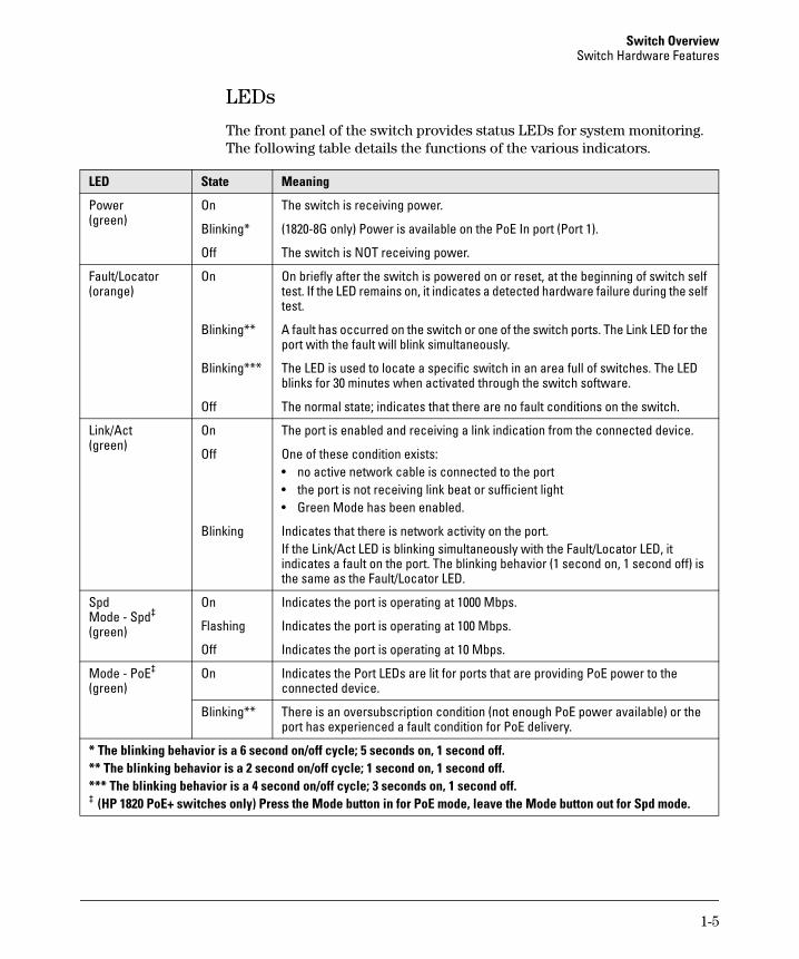
LEDs
The front panel of the switch provides status LEDs for system monitoring. The following table details the functions of the various indicators.
LED State Meaning
Power (green)
On The switch is receiving power.
Blinking* (1820-8G only) Power is available on the PoE In port (Port 1).
Off The switch is NOT receiving power.
Fault/Locator (orange)
On On briefly after the switch is powered on or reset, at the beginning of switch self test. If the LED remains on, it indicates a detected hardware failure during the self test.
Blinking** A fault has occurred on the switch or one of the switch ports. The Link LED for the port with the fault will blink simultaneously.
Blinking*** The LED is used to locate a specific switch in an area full of switches. The LED blinks for 30 minutes when activated through the switch software.
Off The normal state; indicates that there are no fault conditions on the switch.
Link/Act(green)
On The port is enabled and receiving a link indication from the connected device.
Off One of these condition exists:• no active network cable is connected to the port• the port is not receiving link beat or sufficient light• Green Mode has been enabled.
Blinking Indicates that there is network activity on the port.If the Link/Act LED is blinking simultaneously with the Fault/Locator LED, it indicates a fault on the port. The blinking behavior (1 second on, 1 second off) is the same as the Fault/Locator LED.
SpdMode - Spd‡
(green)
On Indicates the port is operating at 1000 Mbps.
Flashing Indicates the port is operating at 100 Mbps.
Off Indicates the port is operating at 10 Mbps.
Mode - PoE‡
(green)On Indicates the Port LEDs are lit for ports that are providing PoE power to the
connected device.
Blinking** There is an oversubscription condition (not enough PoE power available) or the port has experienced a fault condition for PoE delivery.
* The blinking behavior is a 6 second on/off cycle; 5 seconds on, 1 second off.** The blinking behavior is a 2 second on/off cycle; 1 second on, 1 second off.*** The blinking behavior is a 4 second on/off cycle; 3 seconds on, 1 second off.‡ (HP 1820 PoE+ switches only) Press the Mode button in for PoE mode, leave the Mode button out for Spd mode.

1-6
Switch OverviewSwitch Hardware Features
Mode Button
The HP 1820 PoE+ switches have one Mode LED per port. The Mode LED shows either the port speed or the PoE status. In PoE mode, it shows whether the port is configured to provide PoE power. The operation of the Mode LED is controlled by the Mode select button. Press the Mode button in to select the PoE mode, or leave the button in its out position for Spd (speed) mode.
Reset Button
The Reset button is used to restore Factory Default settings, reset the switch while it is powered on, and enable Smart Recover mode.
■ Resetting the Switch — Press and release the button. This action clears any temporary error conditions that may have occurred and executes the switch self test.
■ Restoring Factory Default Configuration — Press and hold down for over 5 seconds, the switch will then complete its self test and begin operating with its configuration restored to the factory default settings. Any configuration changes you may have made through the web browser interface are removed.
■ Enabling Smart Recover Mode — When the switch is booting the Fault LED flashes rapidly three times in succession. Within 2 seconds of the third LED flash, press and hold down the Reset button for 5 seconds. Once the button press is detected, the Fault LED blinks for half a second each second until the button is released.
For more information on Smart Recover mode, see the HP 1820 Switch
Series Management and Configuration Guide.
Power Connector
The 1820-24G, 1820-24G-PoE+, 1820-48G, and 1820-48G-PoE+ Switches do not have a power switch, they are powered on when connected to an active AC power source. The switches automatically adjust to any voltage between 100-127 and 200-240 volts and either 50 or 60 Hz. There are no voltage range settings required.
The 1820-8G and 1820-8G-PoE+ Switches do not have a power switch, they are powered on when the external AC/DC power adapter is connected to the switch and to a power source. The external AC/DC power adapter supplies 12 volts DC to the switch and automatically adjusts to any AC voltage between 100-240 volts and either 50 or 60 Hz. No voltage range settings are required.
The 1820-8G Switch can also be powered on by a PoE PD connection to Port 1.

1-7
Switch OverviewSwitch Features
Switch FeaturesThe features of the HP 1820 Switches include:
■ 8, 24, or 48 auto-sensing 10/100/1000BASE-T RJ-45 ports.
■ 2 or 4 SFP slots for HP SFP transceivers (1820-24G, 1820-24G-PoE+, 1820-48G, and 1820-48G-PoE+ Switches only)
■ plug-and-play networking—all ports are enabled—just connect the network cables to active network devices and your switched network is operational.
■ IEEE 802.3ab Auto MDI /MDI-X on all twisted-pair ports, meaning that all connections can be made using straight-through twisted-pair cables. Cross-over cables are not required, although they will also work. The pin operation of each port is automatically adjusted for the attached device: if the switch detects that a 10/100/1000 Mbps switch or hub is connected to the port, it configures the port as MDI; if the switch detects that a 10/100/1000 Mbps end-node device is connected to the port, it configures the port as MDI-X.
■ all switches support IEEE 802.3az Energy Efficient Ethernet (EEE) features that reduce power consumption when connected with EEE-compliant client devices.
■ automatic learning of MAC addresses in each switch’s 8K-address (8- and 24-port switches) or 16K-address (48-port switches) forwarding table.
■ automatically negotiated full-duplex operation for all 10/100/1000BASE-T RJ-45 ports when connected to other auto-negotiating devices
■ easy management of the switch through several available interfaces:
• Web browser interface — an easy to use built-in graphical interface that can be accessed from common Web browsers.
• Intelligent Management Center (iMC) — allows network administrators to discover and map the switches within their network and launch the built-in graphical interface from within iMC to configure the switches.
■ support for up to 64 IEEE 802.1Q-compliant VLANs so you can divide the attached end nodes into logical groupings that fit your business needs.
■ support for up to 16 trunks (48-port switches) so you can assign physical links to one logical link (trunk) that functions as a single, higher-speed link providing dramatically increased bandwidth.
■ support for many advanced features to enhance network performance—for a description, see the Management and Configuration Guide.
■ download of new switch software for product bug fixes.

1-8
Switch OverviewSwitch Features
2-1
2
Installing the Switch
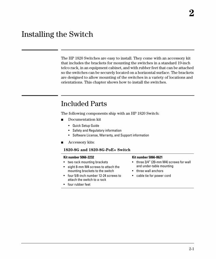
The HP 1820 Switches are easy to install. They come with an accessory kit that includes the brackets for mounting the switches in a standard 19-inch telco rack, in an equipment cabinet, and with rubber feet that can be attached so the switches can be securely located on a horizontal surface. The brackets are designed to allow mounting of the switches in a variety of locations and orientations. This chapter shows how to install the switches.
Included Parts The following components ship with an HP 1820 Switch:
■ Documentation kit
■ Accessory kits:
• Quick Setup Guide• Safety and Regulatory information• Software License, Warranty, and Support information
1820-8G and 1820-8G-PoE+ Switch
Kit number 5066-2232• two rack mounting brackets• eight 8-mm M4 screws to attach the
mounting brackets to the switch• four 5/8-inch number 12-24 screws to
attach the switch to a rack• four rubber feet
Kit number 5066-0621• three 3/4” (20-mm M4) screws for wall
and under-table mounting• three wall anchors• cable tie for power cord

2-2
Installing the SwitchIncluded Parts
■ HP 1820 24- and 48-port switch AC power cords, one of the following:
1820-24G, 1820-24G-PoE+,
and 1820-48G Switch
1820-48G-PoE+ Switch
Kit number 5069-6535• two wall/table mounting brackets• eight 8-mm M4 screws to attach the
mounting brackets to the switch• four 5/8-inch number 12-24 screws to
attach the switch to a rack• four rubber feet
Kit number 5069-5705• two rack mounting brackets• eight 8-mm M4 screws to attach the
mounting brackets to the switch• four 5/8-inch number 12-24 screws to
attach the switch to a rack• four rubber feetKit number 5092-0769• two wall/table mounting brackets
Country/Region
HP 1820-24G, HP 1820-48G,
andHP 1820-24G-PoE+
HP 1820-48G-PoE+1
ArgentinaAustralia/New ZealandBrazilChileChinaContinental EuropeDenmarkIndiaIsraelJapanSwitzerlandSouth AfricaSouth KoreaTaiwanThailandUK/Hong Kong/Singapore/MalaysiaUS/Canada/Mexico
8120-68698121-08348121-10698120-69808120-83778120-68028120-68068121-07808121-10358120-68048120-68078121-09198120-68118121-09648121-06738120-68098120-6805
8120-83758121-08578121-11328120-83898121-10348120-53368120-53408120-53418121-10098120-53428120-53398120-53418120-53368121-09678121-06718120-53348121-0973
1 The cord for the HP 1820-48G-PoE+ Switch supports a higher amperage and uses a C16 connector.

2-3
Installing the SwitchIncluded Parts
■ The 1820-8G external AC/DC power adapters, one of the following:
■ The 1820-8G-PoE+ external AC/DC power adapters and power cords, one of the following:
Japan Power Cord Warning
• Universal Inline AC/DC Power AdapterAll countries/regions 5066-1122
Power Cords for Inline AC/DC Power AdapterAustralia/New ZealandThailandChinaIndiaIsraelJapanSouth AfricaSouth KoreaTaiwanUnited Kingdom/Hong Kong/Singapore/MalaysiaBrazilArgentinaChile
8121-08708121-06648120-83738121-07028120-63148120-63168120-63178120-63148121-09638120-86998121-10818120-83678121-0514
• Wall Plug-in AC/DC Power Adapters(AC Power cords are not used)United States/Canada/MexicoContinental Europe/Denmark/Norway/Sweden/Switzerland/Israel/Vietnam/Indonesia
5184-5863
5184-5864
• Universal Inline AC/DC Power Adapter (model PA2)All countries/regions 5066-2164
Power Cords for Inline AC/DC Power AdapterAustralia/New ZealandChinaContinental EuropeDenmarkIndiaIsraelJapanSouth AfricaSouth KoreaSwitzerlandTaiwanThailandUnited Kingdom/Hong Kong/Singapore/MalaysiaUnited States/Canada/MexicoBrazilArgentinaChile
8121-08348120-83778120-68028120-68068121-07808121-10358120-68048121-09198120-68118120-68078121-09648121-06738120-68098120-68058121-10698120-68698120-6980
2-4
Installing the SwitchIncluded Parts
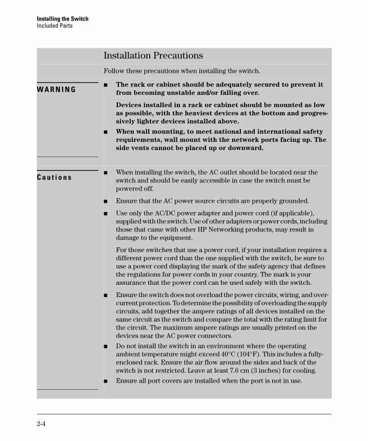
Installation Precautions
Follow these precautions when installing the switch.
W A R N I N G■ The rack or cabinet should be adequately secured to prevent it
from becoming unstable and/or falling over.
Devices installed in a rack or cabinet should be mounted as low
as possible, with the heaviest devices at the bottom and progres-
sively lighter devices installed above.
■ When wall mounting, to meet national and international safety
requirements, wall mount with the network ports facing up. The
side vents cannot be placed up or downward.
C a u t i o n s■ When installing the switch, the AC outlet should be located near the
switch and should be easily accessible in case the switch must be powered off.
■ Ensure that the AC power source circuits are properly grounded.
■ Use only the AC/DC power adapter and power cord (if applicable), supplied with the switch. Use of other adapters or power cords, including those that came with other HP Networking products, may result in damage to the equipment.
For those switches that use a power cord, if your installation requires a different power cord than the one supplied with the switch, be sure to use a power cord displaying the mark of the safety agency that defines the regulations for power cords in your country. The mark is your assurance that the power cord can be used safely with the switch.
■ Ensure the switch does not overload the power circuits, wiring, and over-current protection. To determine the possibility of overloading the supply circuits, add together the ampere ratings of all devices installed on the same circuit as the switch and compare the total with the rating limit for the circuit. The maximum ampere ratings are usually printed on the devices near the AC power connectors.
■ Do not install the switch in an environment where the operating ambient temperature might exceed 40°C (104°F). This includes a fully-enclosed rack. Ensure the air flow around the sides and back of the switch is not restricted. Leave at least 7.6 cm (3 inches) for cooling.
■ Ensure all port covers are installed when the port is not in use.

2-5
Installing the SwitchInstallation Procedure
Installation ProcedureThese steps summarize your switch installation. The rest of this chapter provides details on these steps.
1. Prepare the installation site (page 2-6). Make sure the physical environment into which you will be installing the switch is properly prepared, including having the correct network cabling ready to connect to the switch and having an appropriate location for the switch. See page 2-6 for some installation precautions.
2. Verify the switch passes self test (page 2-6). Plug the switch into a power source and observe that the LEDs on the switch’s front panel indicate correct switch operation.
3. Mount the switch (page 2-9). The HP 1820 24- and 48-port switches can be mounted in a 19-inch telco rack, in an equipment cabinet, on a wall, under a table, or on a horizontal surface. The HP 1820 8-port switches can be mounted on a wall, under a table, or on a horizontal surface.
4. Connect power to the switch (page 2-13). Once the switch is mounted, plug it into the main power source.
5. Connect the network devices (page 2-14). Using the appropriate network cables, connect the network devices to the switch ports.
6. (Optional) Install SFP transceivers (page 2-6). The HP 1820 24- and 48-port switches have slots for installing SFP transceivers. Depending on where you install the switch, it may be easier to install the SFPs first. SFPs can be hot swapped—they can be installed or removed while the switch is powered on.
At this point, your switch is fully installed. See the rest of this chapter if you need more detailed information on any of these installation steps.
2-6
Installing the SwitchInstallation Procedure
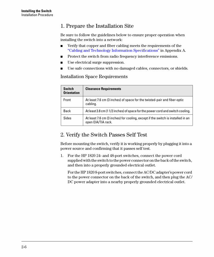
1. Prepare the Installation Site
Be sure to follow the guidelines below to ensure proper operation when installing the switch into a network:
■ Verify that copper and fiber cabling meets the requirements of the “Cabling and Technology Information Specifications” in Appendix A.
■ Protect the switch from radio frequency interference emissions.
■ Use electrical surge suppression.
■ Use safe connections with no damaged cables, connectors, or shields.
Installation Space Requirements
2. Verify the Switch Passes Self Test
Before mounting the switch, verify it is working properly by plugging it into a power source and confirming that it passes self test.
1. For the HP 1820 24- and 48-port switches, connect the power cord supplied with the switch to the power connector on the back of the switch, and then into a properly grounded electrical outlet.
For the HP 1820 8-port switches, connect the AC/DC adapter’s power cord to the power connector on the back of the switch, and then plug the AC/DC power adapter into a nearby properly grounded electrical outlet.
Switch Orientation
Clearance Requirements
Front At least 7.6 cm (3 inches) of space for the twisted-pair and fiber-optic cabling.
Back At least 3.8 cm (1 1/2 inches) of space for the power cord and switch cooling.
Sides At least 7.6 cm (3 inches) for cooling, except if the switch is installed in an open EIA/TIA rack.

2-7
Installing the SwitchInstallation Procedure
N o t e The HP 1820 24- and 48-port switches do not have a power switch. They are powered on when the power cord is connected to the switch and to a power source. For safety, the power outlet should be located near the switch installation.
The switches automatically adjusts to any voltage between 100-127 or 200-240 volts and either 50 or 60 Hz. There are no voltage range settings required.
Connect the power cord to the switch and an AC power outlet
HP 1820-8G Switch
HP 1820 24- and 48-Port Switches
Connect wall plug-in AC/DC power adapter to the switch and an AC power outlet
HP 1820-8G-PoE+ Switch
Connect inline AC/DC power adapter to the switch and an AC power outlet

2-8
Installing the SwitchInstallation Procedure
The HP 1820 8-port switches also do not have a power switch. They are powered on when the external AC/DC power adapter is connected to the switch and the adapter power cord to a power source. The external AC/DC power adapter automatically adjusts to any voltage between 100-240 volts and either 50 or 60 Hz.
2. Check the LEDs on the switch as described below.
When the switch is powered on, it performs its diagnostic self test. The self test takes approximately 45 seconds to complete.
Self Test LED Behavior:
During the self test:
• Initially, the Power, Fault/Locator, and all port LEDs turn on.
• After several seconds, the Power and Fault/Locator LEDs remain on, and the port LEDs turn off. Then each port Link LED is sequentially turned on, then off.
Power and Fault/Locator LEDs
Port Link/Act and Speed LEDs
Port Link/Act and Mode LEDs

2-9
Installing the SwitchInstallation Procedure
• The Fault/Locator LED turns off when the self test completes.
When the self test completes successfully:
• The Power LED remains on.
• The Fault/Locator LED stays off.
• The port LEDs on the front of the switch go into their normal opera-tional mode:– If the ports are connected to active network devices, the Link/Act
LEDs stay on or may be blinking to indicate port activity. The Spd LEDs turn on for 1000 Mbps links, blink for 100 Mbps links, or stay off for 10 Mbps links. On the PoE+ switches, the Mode LEDs behave according to the mode selected. In the default mode (Spd), the Mode LEDs should be on for 1000 Mbps links, blink for 100 Mbps links, or stay off for 10 Mbps links.
– If the ports are not connected to active network devices, the Link/Act and Spd LEDs will stay off.
If the LED display is different than what is described above, the self test has not completed correctly. Refer to “Troubleshooting” for diagnostic help.
3. Remove power to the switch before mounting.
3. Mount the Switch
The switch can be mounted in these ways:■ on a horizontal surface■ on a wall■ under a table■ in a rack or cabinet
Rack or Cabinet Mounting
The switches are designed to be mounted in any EIA-standard 19-inch telco rack or communication equipment cabinet. Note that the mounting brackets have multiple mounting holes and can be rotated allowing for a wide variety of mounting options.
W A R N I N G For safe operation, please read the “Installation Precautions” on
page 2-4 before mounting the switch.
2-10
Installing the SwitchInstallation Procedure
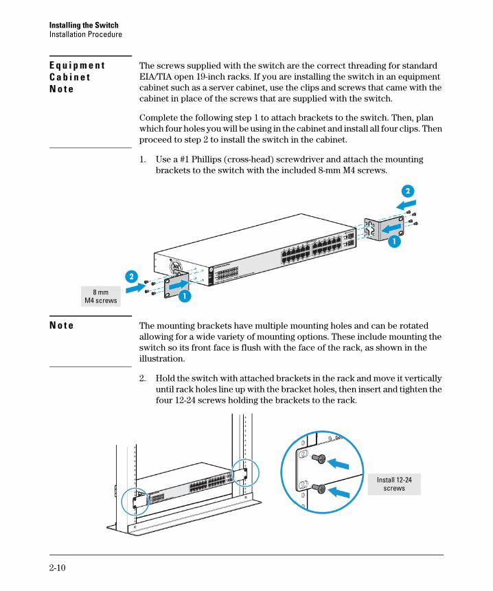
E q u i p m e n t C a b i n e t N o t e
The screws supplied with the switch are the correct threading for standard EIA/TIA open 19-inch racks. If you are installing the switch in an equipment cabinet such as a server cabinet, use the clips and screws that came with the cabinet in place of the screws that are supplied with the switch.
Complete the following step 1 to attach brackets to the switch. Then, plan which four holes you will be using in the cabinet and install all four clips. Then proceed to step 2 to install the switch in the cabinet.
1. Use a #1 Phillips (cross-head) screwdriver and attach the mounting brackets to the switch with the included 8-mm M4 screws.
N o t e The mounting brackets have multiple mounting holes and can be rotated allowing for a wide variety of mounting options. These include mounting the switch so its front face is flush with the face of the rack, as shown in the illustration.
2. Hold the switch with attached brackets in the rack and move it vertically until rack holes line up with the bracket holes, then insert and tighten the four 12-24 screws holding the brackets to the rack.
8 mmM4 screws
Install 12-24 screws
2-11
Installing the SwitchInstallation Procedure
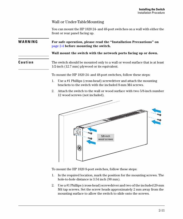
Wall or Under-TableMounting
You can mount the HP 1820 24- and 48-port switches on a wall with either the front or rear panel facing up.
W A R N I N G For safe operation, please read the “Installation Precautions” on
page 2-4 before mounting the switch.
Wall mount the switch with the network ports facing up or down.
C a u t i o n The switch should be mounted only to a wall or wood surface that is at least 1/2-inch (12.7 mm) plywood or its equivalent.
To mount the HP 1820 24- and 48-port switches, follow these steps:
1. Use a #1 Phillips (cross-head) screwdriver and attach the mounting brackets to the switch with the included 8-mm M4 screws.
2. Attach the switch to the wall or wood surface with two 5/8-inch number 12 wood screws (not included).
To mount the HP 1820 8-port switches, follow these steps:
1. In the required location, mark the position for the mounting screws. The hole-to-hole distance is 3.54 inch (90 mm).
2. Use a #1 Phillips (cross-head) screwdriver and two of the included 20-mm M4 tap screws. Set the screw heads approximately 2 mm away from the mounting surface to allow the switch to slide onto the screws.
5/8-inch wood screws

2-12
Installing the SwitchInstallation Procedure
Wall anchors are included in the accessory kit for use with plastered brick or concrete walls.
3. For under-table mounting, a third 20-mm M4 tap screw can be placed against one side of the switch to secure it in place.
Horizontal Surface Mounting
Place the switch on a table or other horizontal surface. The switch comes with rubber feet in the accessory kit that can be used to help keep the switch from sliding on the surface.
Attach the rubber feet to the four corners on the bottom of the switch within the embossed angled lines. Use a sturdy surface in an uncluttered area. You may want to secure the networking cables and switch power cord to the table leg or other part of the surface structure to help prevent tripping over the cords.
20-mm M4 tap screws
Wall anchors
2-13
Installing the SwitchInstallation Procedure
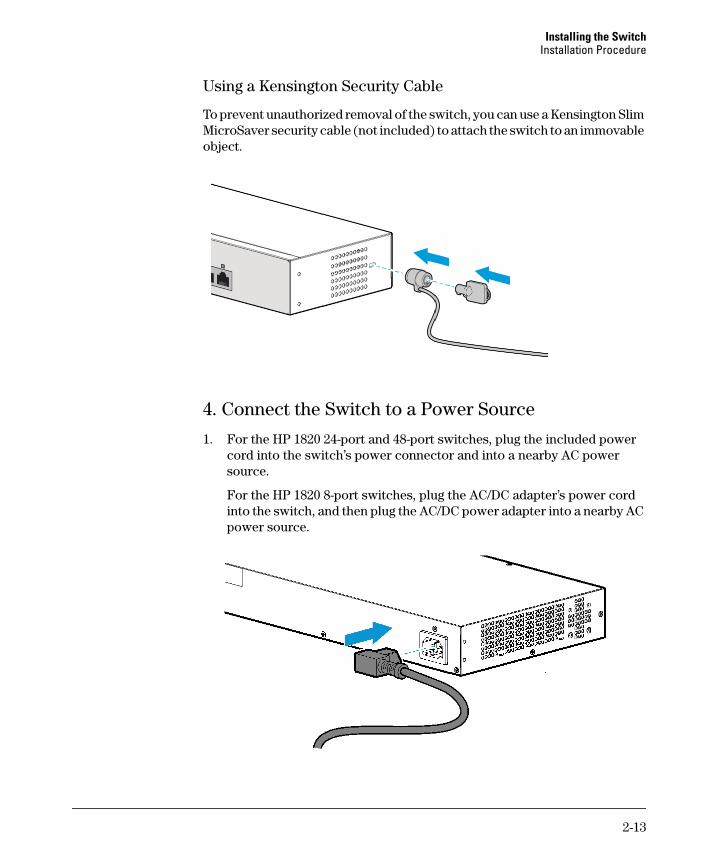
Using a Kensington Security Cable
To prevent unauthorized removal of the switch, you can use a Kensington Slim MicroSaver security cable (not included) to attach the switch to an immovable object.
4. Connect the Switch to a Power Source
1. For the HP 1820 24-port and 48-port switches, plug the included power cord into the switch’s power connector and into a nearby AC power source.
For the HP 1820 8-port switches, plug the AC/DC adapter’s power cord into the switch, and then plug the AC/DC power adapter into a nearby AC power source.
2-14
Installing the SwitchInstallation Procedure
2.) Re-check the LEDs during self test. See “Self Test LED Behavior” on page 2-8.
3. For the HP 1820 8-port switches, use the included cable tie to secure the power cord to the switch.
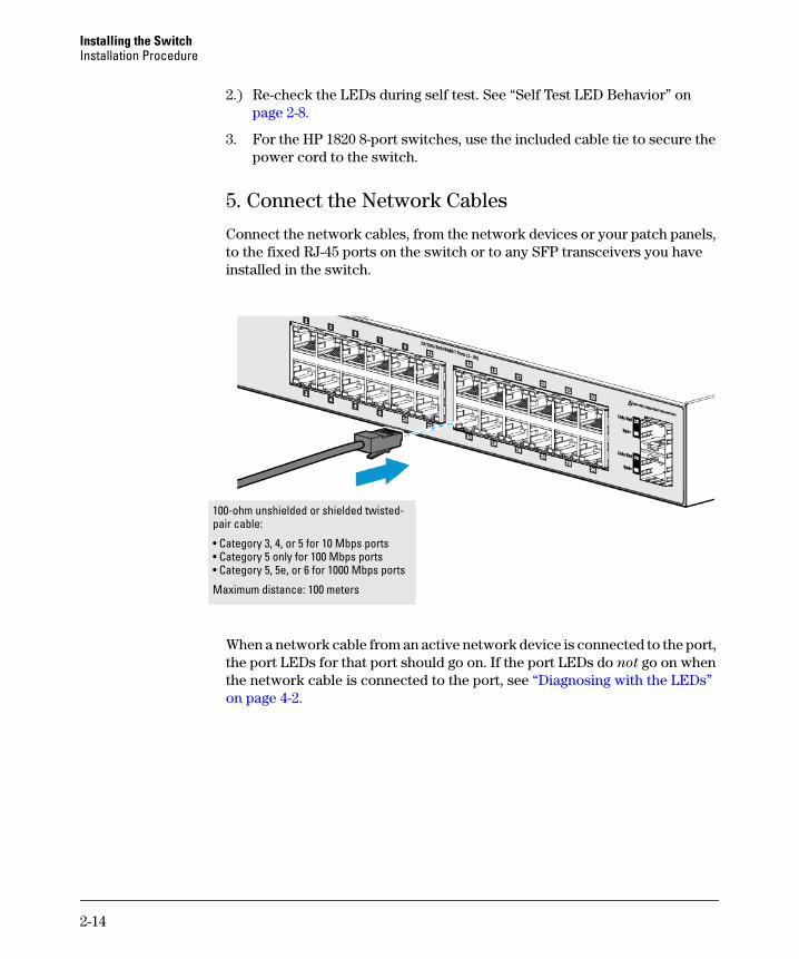
5. Connect the Network Cables
Connect the network cables, from the network devices or your patch panels, to the fixed RJ-45 ports on the switch or to any SFP transceivers you have installed in the switch.
When a network cable from an active network device is connected to the port, the port LEDs for that port should go on. If the port LEDs do not go on when the network cable is connected to the port, see “Diagnosing with the LEDs” on page 4-2.
100-ohm unshielded or shielded twisted-pair cable:
• Category 3, 4, or 5 for 10 Mbps ports• Category 5 only for 100 Mbps ports• Category 5, 5e, or 6 for 1000 Mbps ports
Maximum distance: 100 meters

2-15
Installing the SwitchInstallation Procedure
6. Installing or Removing SFPs
You can install or remove an SFP from an SFP slot without having to power off the switch. Use only HP SFPs (see table on page 1-4).
C a u t i o n Hot swapping transceivers is supported. You can install or remove a transceiver with the switch powered on, a reset will not occur. However, rapid hotswaps are not recommended. Wait a few seconds for the Mode LED to turn on (during initialization), and then turn off.
N o t e s Ensure the network cable is NOT connected when you install or remove an SFP.
C a u t i o n Use only supported genuine HP SFPs with your switch. Non-HP SFPs are not supported, and their use may result in product malfunction. Should you require additional HP SFPs, contact your HP Networking Sales and Service Office or authorized dealer.
Installing the SFPs:
Remove the protective plastic cover and retain it for later use. Hold the SFP by its sides and gently insert it into any of the slots on the switch until the SFP clicks into place.
W A R N I N G The HP SFPs are Class 1 laser devices. Avoid direct eye exposure to
the beam coming from the transmit port.

2-16
Installing the SwitchInstallation Procedure
Removing the SFPs:
N o t e You should disconnect the network cable from the SFP before
removing it from the switch.
Depending on when you purchased your HP SFP, it may have either of three different release mechanisms: a plastic tab on the bottom of the SFP, a plastic collar around the SFP, or a wire bail.
To remove the SFPs that have the plastic tab or plastic collar, push the tab or collar toward the switch until you see the SFP release from the switch (you can see it move outward slightly), and then pull it from the slot.
To remove the SFPs that have the wire bail, lower the bail until it is approximately horizontal, and then using the bail, pull the SFP from the slot.
Replace the protective plastic cover on the SFP.
Connecting Cables to SFPs
If you have any SFPs installed in the switch, the type of network connections you will need to use depends on the type of SFPs you have installed. See the table on page 1-4, and appendix A, “Specifications”, for the SFP cabling information.
For SFP ports, and in general for all the switch ports, when a network cable from an active network device is connected to the port, the port Link LED for that port should go on. If the port Link LED does not go on when the network cable is connected to the port, see “Diagnosing with the LEDs” in chapter 4, “Troubleshooting”.

3-1
3
Configuring the Switch
Initial Configuration
The HP 1820 Switch Series can be managed through a Web-browser interface that you can access from any PC or workstation connected to the switch.
To access the Web interface, you must have the switch’s Internet Protocol (IP) address. In the factory default configuration, the IP address is automatically acquired from a Dynamic Host Configuration Protocol (DHCP) service that is available on your network or from your Internet Service Provider (ISP). Most routers provide this service. The DHCP service automatically provides a network IP address configuration to devices that request it, such as the HP 1820 switches.
Many features are configurable on the HP 1820 Switch Series. HP recommends that at minimum, you configure a management password for switch security. Follow these procedures to access the switch’s Web interface to perform the switch configuration:
1. Place the switch close to the PC that you will use for configuration. It helps if you can see the front panel of the switch while working from your PC.
2. Connect power to the switch, and then start your PC (if it is not already running) and wait until the switch and PC have finished their start-up sequences.
3. Connect the PC to any port on the switch using a standard Ethernet LAN cable. Verify that there is a link between the switch and PC by checking the LEDs for the network port that you are using. (For more information on LEDs, see “LEDs” on page 1-5.)
4. If the switch has access to a DHCP service, it automatically acquires an IP address. Determine the IP address of the switch by examining the client IP address table on your router (see the router documentation for how to get this information), or talk to your ISP representative to get the IP address of the switch.
3-2
Configuring the SwitchInitial Configuration
If a DHCP service is not available in your network, or for some reason the switch does not acquire an IP address from the service, the switch defaults to IP address 192.168.1.1 after 120 seconds of automatically attempting to acquire an IP address.
N o t e Alternatively, if you cannot determine the switch’s IP address, you can force it to use the 192.168.1.1 address by first disconnecting the switch from any router or internet connection and then unplugging and recon-necting power to it.
To communicate with the switch using the 192.168.1.1 address, see the section “Using the 192.168.1.1 IP Address” on page 3-3 before continuing these steps.
5. From the PC connected to the switch, open a Web-browser session and enter the switch’s IP address as the URL. This opens the login screen for the switch’s Web browser interface from which you perform the next steps.
6. Enter the default username “admin” and click Login to start a switch Web-browser interface session. By default, there is no password.
7. To configure a password on the switch Web interface, click Maintenance
> Password Manager and enter the Current Password. Define a New
Password and reenter it in the Confirm New Password field. Passwords can be up to 64 alphanumeric and special characters in length, and are case sensitive.
8. Click Apply to implement the new password, and then click Save Config-
uration at the top of the browser configuration screen to save your settings and retain them when the switch is rebooted.
See the HP 1820 Switch Series Management and Configuration Guide for more switch configuration information.
N o t e If you cannot remember the switch’s IP address or password, you can restore the factory default settings by following the procedure described in the “Troubleshooting” section.
3-3
Configuring the SwitchUsing the 192.168.1.1 IP Address
Using the 192.168.1.1 IP Address
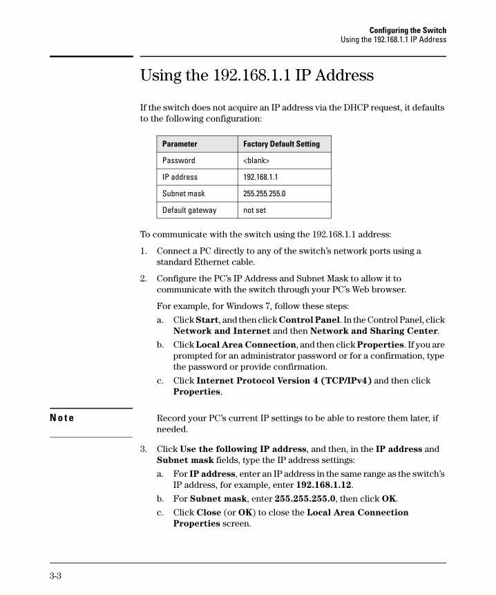
If the switch does not acquire an IP address via the DHCP request, it defaults to the following configuration:
To communicate with the switch using the 192.168.1.1 address:
1. Connect a PC directly to any of the switch’s network ports using a standard Ethernet cable.
2. Configure the PC’s IP Address and Subnet Mask to allow it to communicate with the switch through your PC’s Web browser.
For example, for Windows 7, follow these steps:
a. Click Start, and then click Control Panel. In the Control Panel, click Network and Internet and then Network and Sharing Center.
b. Click Local Area Connection, and then click Properties. If you are prompted for an administrator password or for a confirmation, type the password or provide confirmation.
c. Click Internet Protocol Version 4 (TCP/IPv4) and then click Properties.
N o t e Record your PC’s current IP settings to be able to restore them later, if needed.
3. Click Use the following IP address, and then, in the IP address and Subnet mask fields, type the IP address settings:
a. For IP address, enter an IP address in the same range as the switch’s IP address, for example, enter 192.168.1.12.
b. For Subnet mask, enter 255.255.255.0, then click OK.
c. Click Close (or OK) to close the Local Area Connection
Properties screen.
Parameter Factory Default Setting
Password <blank>
IP address 192.168.1.1
Subnet mask 255.255.255.0
Default gateway not set

3-4
Configuring the SwitchWhere to Go From Here
4. Open the Web browser on the PC, and enter the switch address, http://192.168.1.1 to access the switch’s Web interface. Go back to step 6 on the page 3-2 to configure the switch.
Where to Go From Here
For more information on the Web browser interface and all the features that can be configured on the HP 1820 Switch Series, see the HP 1820 Switch
Series Management and Configuration Guide, which is available on the HP Web site, http://www.hp.com/support/manuals.
4-1
4
Troubleshooting
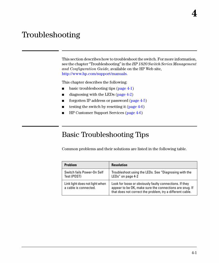
This section describes how to troubleshoot the switch. For more information, see the chapter “Troubleshooting” in the HP 1820 Switch Series Management
and Configuration Guide, available on the HP Web site, http://www.hp.com/support/manuals.
This chapter describes the following:
■ basic troubleshooting tips (page 4-1)
■ diagnosing with the LEDs (page 4-2)
■ forgotten IP address or password (page 4-5)
■ testing the switch by resetting it (page 4-6)
■ HP Customer Support Services (page 4-6)
Basic Troubleshooting Tips
Common problems and their solutions are listed in the following table.
Problem Resolution
Switch fails Power-On Self Test (POST)
Troubleshoot using the LEDs. See “Diagnosing with the LEDs” on page 4-2
Link light does not light when a cable is connected.
Look for loose or obviously faulty connections. If they appear to be OK, make sure the connections are snug. If that does not correct the problem, try a different cable.
4-2
TroubleshootingDiagnosing with the LEDs
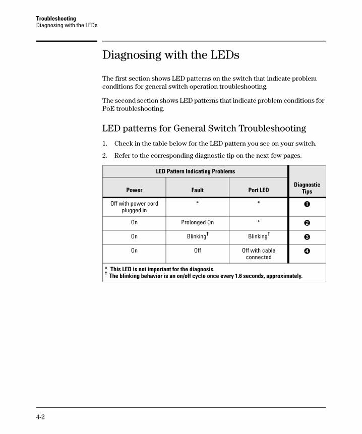
Diagnosing with the LEDs
The first section shows LED patterns on the switch that indicate problem conditions for general switch operation troubleshooting.
The second section shows LED patterns that indicate problem conditions for PoE troubleshooting.
LED patterns for General Switch Troubleshooting
1. Check in the table below for the LED pattern you see on your switch.
2. Refer to the corresponding diagnostic tip on the next few pages.
LED Pattern Indicating Problems
Diagnostic TipsPower Fault Port LED
Off with power cord plugged in
* * ➊
On Prolonged On * ➋
On Blinking† Blinking†➌
On Off Off with cable connected
➍
* This LED is not important for the diagnosis.† The blinking behavior is an on/off cycle once every 1.6 seconds, approximately.
4-3
TroubleshootingDiagnosing with the LEDs
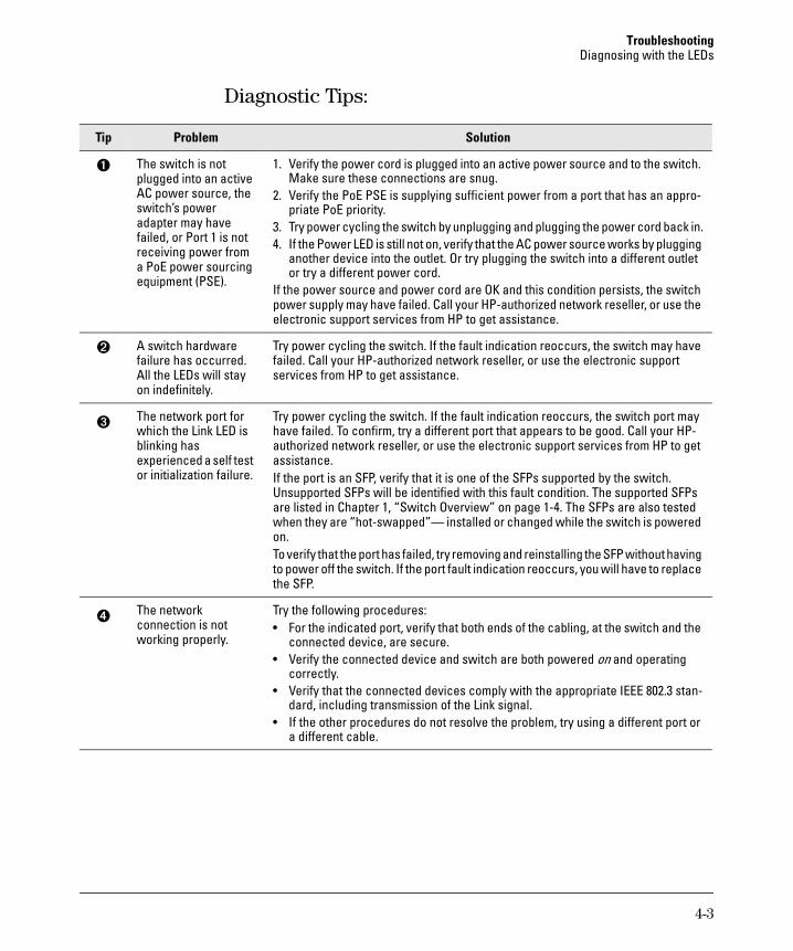
Diagnostic Tips:
Tip Problem Solution
➊ The switch is not plugged into an active AC power source, the switch’s power adapter may have failed, or Port 1 is not receiving power from a PoE power sourcing equipment (PSE).
1. Verify the power cord is plugged into an active power source and to the switch. Make sure these connections are snug.
2. Verify the PoE PSE is supplying sufficient power from a port that has an appro-priate PoE priority.
3. Try power cycling the switch by unplugging and plugging the power cord back in.4. If the Power LED is still not on, verify that the AC power source works by plugging
another device into the outlet. Or try plugging the switch into a different outlet or try a different power cord.
If the power source and power cord are OK and this condition persists, the switch power supply may have failed. Call your HP-authorized network reseller, or use the electronic support services from HP to get assistance.
➋ A switch hardware failure has occurred. All the LEDs will stay on indefinitely.
Try power cycling the switch. If the fault indication reoccurs, the switch may have failed. Call your HP-authorized network reseller, or use the electronic support services from HP to get assistance.
➌ The network port for which the Link LED is blinking has experienced a self test or initialization failure.
Try power cycling the switch. If the fault indication reoccurs, the switch port may have failed. To confirm, try a different port that appears to be good. Call your HP-authorized network reseller, or use the electronic support services from HP to get assistance. If the port is an SFP, verify that it is one of the SFPs supported by the switch. Unsupported SFPs will be identified with this fault condition. The supported SFPs are listed in Chapter 1, “Switch Overview” on page 1-4. The SFPs are also tested when they are “hot-swapped”— installed or changed while the switch is powered on.To verify that the port has failed, try removing and reinstalling the SFP without having to power off the switch. If the port fault indication reoccurs, you will have to replace the SFP.
➍ The network connection is not working properly.
Try the following procedures:• For the indicated port, verify that both ends of the cabling, at the switch and the
connected device, are secure.• Verify the connected device and switch are both powered on and operating
correctly.• Verify that the connected devices comply with the appropriate IEEE 802.3 stan-
dard, including transmission of the Link signal.• If the other procedures do not resolve the problem, try using a different port or
a different cable.
4-4
TroubleshootingDiagnosing with the LEDs
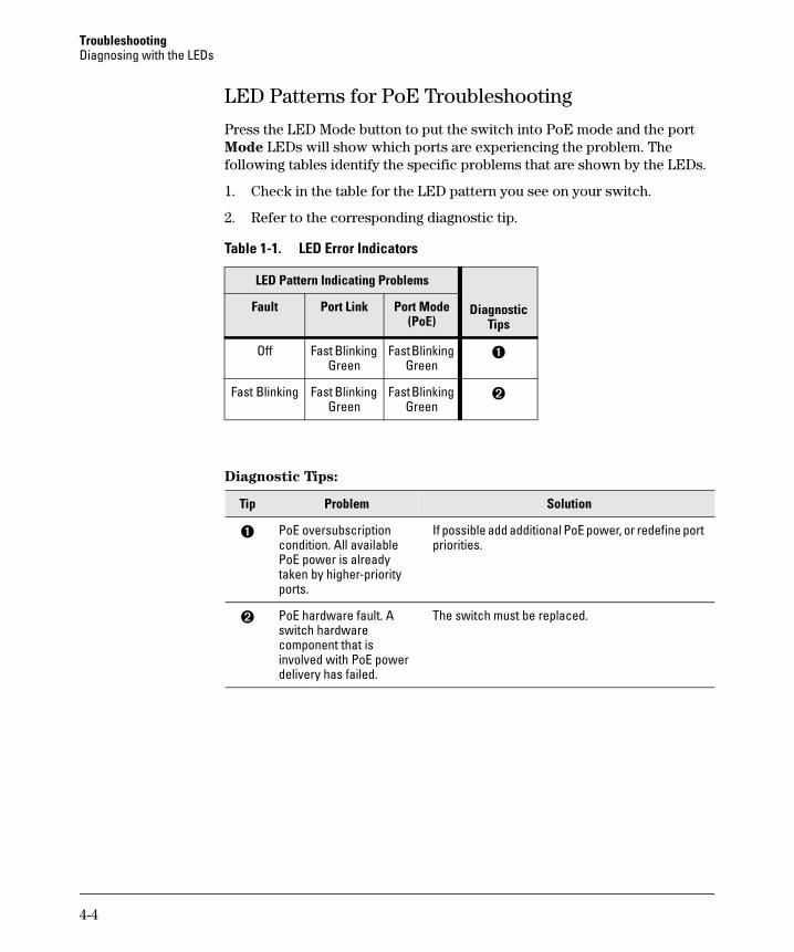
LED Patterns for PoE Troubleshooting
Press the LED Mode button to put the switch into PoE mode and the port Mode LEDs will show which ports are experiencing the problem. The following tables identify the specific problems that are shown by the LEDs.
1. Check in the table for the LED pattern you see on your switch.
2. Refer to the corresponding diagnostic tip.
Table 1-1. LED Error Indicators
Diagnostic Tips:
LED Pattern Indicating Problems
Diagnostic Tips
Fault Port Link Port Mode(PoE)
Off Fast Blinking Green
Fast Blinking Green
➊
Fast Blinking Fast Blinking Green
Fast Blinking Green
➋
Tip Problem Solution
➊ PoE oversubscription condition. All available PoE power is already taken by higher-priority ports.
If possible add additional PoE power, or redefine port priorities.
➋ PoE hardware fault. A switch hardware component that is involved with PoE power delivery has failed.
The switch must be replaced.

4-5
TroubleshootingTesting the Switch by Resetting It
Testing the Switch by Resetting It
If you believe the switch is not operating correctly, you can reset the switch to test its circuitry and operating code. To reset the switch, unplug and plug in the power cord (power cycling).
Power cycling the switch will cause the switch to perform its power-on self test. Resetting the switch can also be invoked from the Web interface.
Restoring to Factory Defaults
If you forget the switch IP address or password, you can restore the factory default configuration by pressing the Reset button.
To execute the factory default reset on the switch, perform these steps:
1. Using a small, thin tool with blunt ends (such as a paper clip), press the Reset button on the front of the switch.
2. Continue to press the Reset button for more than 5 seconds.
3. Release the Reset button.
The switch will then complete its self test and begin operating with its configuration restored to the factory default settings.
After completing this procedure, there will be no password, the IP address will be returned to the default 192.168.1.1, and all configuration settings will be returned to factory defaults.

4-6
TroubleshootingHP Customer Support Services
HP Customer Support Services
If you are still having trouble with your switch, Hewlett-Packard offers support 24 hours a day, seven days a week through the use of a number of automated electronic services.
The HP Web site, http://www.hp.com/networking/support also provides up-to-date support information.
Additionally, your HP authorized network reseller can provide you with assistance, both with services they offer and with services offered by HP.
Before Calling Support
Before calling your networking dealer or HP Support, to make the support process most efficient, you first should have retrieved the following information:
Information Item Information Location
• product identification, including SFPs the front of the switch, and on labels on the SFPs
• details about the switch’s status includ-ing the operating software (OS) ver-sion, a copy of the switch configuration, and contents of the Support file
Web interface.For more information on using the Web interface, see the Management and Configuration Guide for your switch.
• copy of your network topology map, in-cluding network addresses assigned to the relevant devices
your network records

A-1
A
Specifications
Switch Specifications
Physical
Electrical
1 Requires a connection to an external power adapter. The adapter automati-cally adjusts to any voltage between 100 and 240 volts and either 50 or 60 Hz.
Width Depth Height Weight
1820-8G (J9979A) 25.4 cm (10.0 in) 15.95 cm (6.28 in) 4.4 cm (1.73 in) 0.8 kg (1.8 lb)
1820-24G (J9980A) 44.25 cm (17.42 in) 24.61 cm (9.69 in) 4.4 cm (1.73 in) 2.7 kg (6.0 lb)
1820-48G (J9981A) 44.25 cm (17.42 in) 24.61 cm (9.69 in) 4.4 cm (1.73 in) 3.3 kg (7.3 lb)
1820-8G-PoE+ (J9982A) 25.40 cm (10.0 in) 15.95 cm (6.28 in) 4.4 cm (1.73 in) 0.9 kg (2.0 lb)
1820-24G-PoE+ (J9983A) 44.25 cm (17.42 in) 24.61 cm (9.69 in) 4.4 cm (1.73 in) 3.3 kg (7.3 lb)
1820-48G-PoE+ (J9984A) 44.25 cm (17.42 in) 32.26 cm (12.7 in) 4.4 cm (1.73 in) 4.4 kg (9.7 lb)
AC voltage Maximum current Frequency range
1820-8G (J9979A)1,3 100-240 volts 0.2 A 50/60 Hz
1820-24G (J9980A)2 100-127 volts200-240 volts
0.5 A / 0.3 A 50/60 Hz
1820-48G (J9981A)2 100-127 volts200-240 volts
0.7 A / 0.4 A 50/60 Hz
1820-8G-PoE+ (J9982A)1 100-240 volts 0.9 A 50/60 Hz
1820-24G-PoE+ (J9983A)2 100-127 volts200-240 volts
2.6 A / 1.3 A 50/60 Hz
1820-48G-PoE+ (J9984A)2 100-127 volts200-240 volts
5 A / 2.5 A 50/60 Hz

A-2
SpecificationsSwitch Specifications
2 The switch automatically adjusts to any voltage between 100-127 or 200-240 volts and either 50 or 60 Hz.
3 The switch can also be powered by a PoE PD connection to Port 1. Port 1 is an IEEE 802.3af Compatible PD (PoE Powered Device) - Class 3.
Environmental
* The operating maximum altitude should not exceed that of any accessory being connected to any 1820 Switch.
Acoustics
1820-8G, 1820-24G, 1820-48G, and 1820-8G-PoE+ Switches:Power: 0 dB (no fans)
Safety
Complies with:
■ EN60950-1:2006+A11:2009+A1:2010+A12:2011 / IEC60950-1:2005; Am1:2009;
■ CSA22.2 No. 60950-1-07 2nd; UL60950-1 2nd
■ EN 60825-1:2007 / IEC 60825-1:2007 Class 1
Operating Non-Operating
Temperature 0°C to 40°C (32°F to 104°F) -40°C to 70°C (-40°F to 158°F)
Relative humidity(non-condensing)
15% to 95% at 40°C (104°F) 15% to 95% at 65°C (149°F)
Maximum altitude 3.0 Km (10,000 ft)* 4.57 Km (15,000 ft)
Noise Emmission
1820-24G-PoE+(J9983A)
Geraeuschemission LpA=37.9 dB am fiktiven Arbeitsplatz nach DIN 45635 T.19Noise Emission LpA=37.9 dB at virtual workspace according to DIN 45635 T.19
1820-48G-PoE+(J9984A)
Geraeuschemission LpA=45 dB am fiktiven Arbeitsplatz nach DIN 45635 T.19Noise Emission LpA=45 dB at virtual workspace according to DIN 45635 T.19

A-3
SpecificationsStandards
Standards
Laser safety information
Technology Compatible with these IEEE standards
EN/IEC standard compliance
SFP Lasers
10-T
100-TX
1000-T
IEEE 802.3 10BASE-T
IEEE 802.3u 100BASE-TX
IEEE 802.3ab 1000BASE-T
100-FX IEEE 802.3u 100BASE-FX EN/IEC 60825 Class 1 Laser ProductLaser Klasse 1
1000-SX IEEE 802.3z 1000BASE-SX EN/IEC 60825 Class 1 Laser ProductLaser Klasse 1
1000-LX IEEE 802.3z 1000BASE-LX EN/IEC 60825 Class 1 Laser ProductLaser Klasse 1

A-4
SpecificationsCabling and Technology Information Specifications
Cabling and Technology Information Specifications
Note on 1000BASE-T Cable Requirements. The Category 5 networking cables that work for 100BASE-TX connections should also work for 1000BASE-T, as long as all four-pairs are connected. But, for the most robust connections, you should use cabling that complies with the Category 5e specifications, as described in Addendum 5 to the TIA-568-A standard (ANSI/TIA/EIA-568-A-5).
Because of the increased speed provided by 1000BASE-T (Gigabit-T), network cable quality is more important than for either 10BASE-T or 100BASE-TX. Cabling plants being used to carry 1000BASE-T networking must comply with the IEEE 802.3ab standards. In particular, the cabling must pass tests for Attenuation, Near-End Crosstalk (NEXT), and Far-End Crosstalk (FEXT). Additionally, unlike the cables for 100BASE-TX, the 1000BASE-T cables must pass tests for Equal-Level Far-End Crosstalk (ELFEXT) and Return Loss.
When testing your cabling, be sure to include the patch cables that connect the switch and other end devices to the patch panels on your site. The patch cables are frequently overlooked when testing cable and they must also comply with the cabling standards.
Twisted-pair copper
10 Mbps Operation Category 3, 4 or 5, 100-ohm unshielded twisted-pair (UTP) or shielded twisted-pair (STP) cable, complying with IEEE 802.3 10BASE-T specifications.
100 Mbps Operation Category 5, 100-ohm UTP or STP cable, complying with IEEE 802.3u 100BASE-TX specifications.
1000 Mbps Operation Category 5, 100-ohm 4-pair UTP or STP cable, complying with IEEE 802.3ab 1000BASE-T specifications—Category 5e or better is recommended. See note on 1000BASE-T Cable Requirements below.
Multimode fiber62.5/125 μm or 50/125 μm (core/cladding) diameter, low metal content, graded index fiber-optic cables, complying with theITU-T G.651 and ISO/IEC 793-2 Type A1b or A1a standardsrespectively.1
Single mode fiber9/125 μm (core/cladding) diameter, low metal content fiber-optic cables, complying with the ITU-T G.652 andISO/IEC 793-2 Type B1 standards.
1 A mode conditioning patch cord may be needed for some Gigabit-LX installations. See “Mode Conditioning Patch Cord” on page A-5 for more information.

A-5
SpecificationsMode Conditioning Patch Cord
Technology Distance Specifications
Mode Conditioning Patch Cord
The following information applies to installations in which multimode fiber-optic cables are connected to a Gigabit-LX port. Multimode cable has a design characteristic called “Differential Mode Delay”, which requires the transmission signals be “conditioned” to compensate for the cable design and thus prevent resulting transmission errors.
Under certain circumstances, depending on the cable used and the lengths of the cable runs, an external Mode Conditioning Patch Cord may need to be installed between the Gigabit-LX transmitting device and the multimode network cable to provide the transmission conditioning. If you experience a high number of transmission errors on those ports, usually CRC or FCS errors, you may need to install one of these patch cords between the fiber-optic port in your switch and your multimode fiber-optic network cabling, at both ends of the network link.
The patch cord consists of a short length of single mode fiber cable coupled to graded-index multimode fiber cable on the transmit side, and only multimode cable on the receive side. The section of single mode fiber is connected in such a way that it minimizes the effects of the differential mode delay in the multimode cable.
Technology Supported cable type Multimode fibermodal bandwidth
Supported distances
100-FX multimode fiber any up to 2,000 meters
1000-T twisted-pair copper N/A up to 100 meters
1000-SX multimode fiber 160 MHz*km200 MHz*km400 MHz*km500 MHz*km
2 - 220 meters2 - 275 meters2 - 500 meters2 - 550 meters
1000-LX multimode fiber
single mode fiber
400 MHz*km500 MHz*kmN/A
2 - 550 meters2 - 550 meters2 - 10,000 meters
A-6
SpecificationsMode Conditioning Patch Cord
N o t e Most of the time, if you are using good quality graded-index multimode fiber cable that adheres to the standards listed in this appendix, there should not be a need to use mode conditioning patch cords in your network. This is especially true if the fiber runs in your network are relatively short.
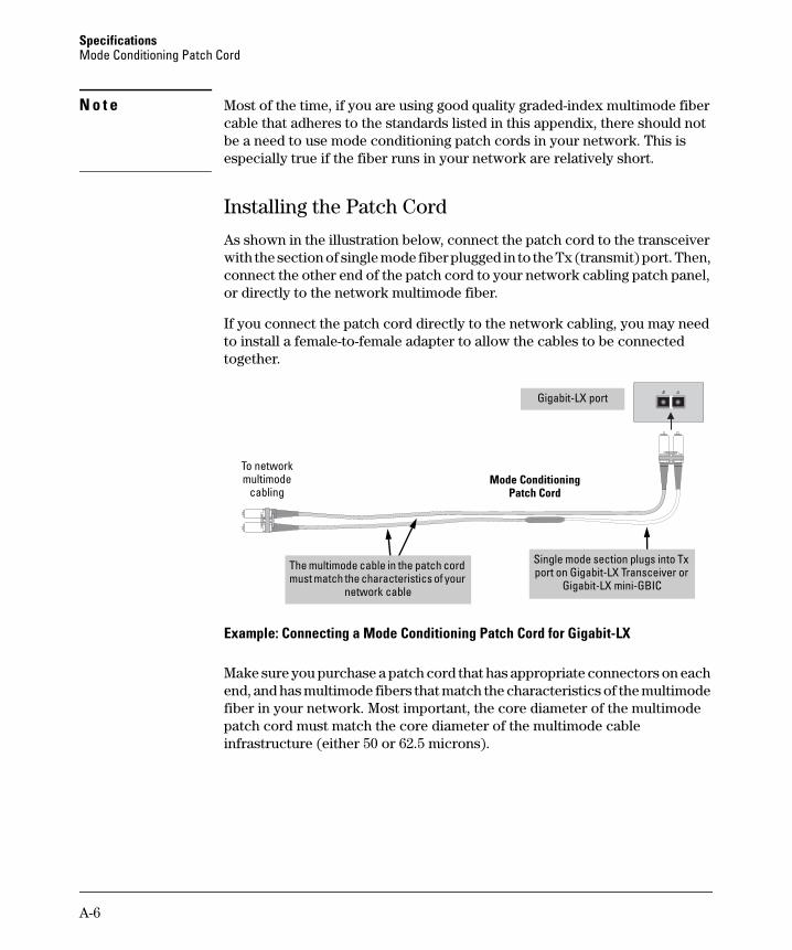
Installing the Patch Cord
As shown in the illustration below, connect the patch cord to the transceiver with the section of single mode fiber plugged in to the Tx (transmit) port. Then, connect the other end of the patch cord to your network cabling patch panel, or directly to the network multimode fiber.
If you connect the patch cord directly to the network cabling, you may need to install a female-to-female adapter to allow the cables to be connected together.
Example: Connecting a Mode Conditioning Patch Cord for Gigabit-LX
Make sure you purchase a patch cord that has appropriate connectors on each end, and has multimode fibers that match the characteristics of the multimode fiber in your network. Most important, the core diameter of the multimode patch cord must match the core diameter of the multimode cable infrastructure (either 50 or 62.5 microns).
Tx
Rx
To network multimode
cablingMode Conditioning
Patch Cord
The multimode cable in the patch cord must match the characteristics of your
network cable
Gigabit-LX port
Single mode section plugs into Tx port on Gigabit-LX Transceiver or
Gigabit-LX mini-GBIC

A-7
SpecificationsTwisted-Pair Cable/Connector Pin-Outs
Twisted-Pair Cable/Connector Pin-Outs
The Auto-MDIX Feature: In the default configuration, “Auto”, the fixed 10/100/1000BASE-T ports on the switches all automatically detect the type of port on the connected device and operate as either an MDI or MDI-X port, whichever is appropriate. So for any connection, a straight-through twisted-pair cable can be used—you no longer have to use crossover cables, although crossover cables can also be used for any of the connections. (The 10/100/1000-T ports support the IEEE 802.3ab standard, which includes the “Auto-MDIX” feature.)
If you connect a switch twisted-pair port to another switch or hub, which typically have MDI-X ports, the switch port automatically operates as an MDI port. If you connect it to an end node, such as a server or PC, which typically have MDI ports, the switch port operates as an MDI-X port. In all cases, you can use standard straight-through cables or crossover cables.
If you happen to use a correctly wired crossover cable, though, the switch will still be able to automatically detect the MDI/MDI-X operation and link correctly to the connected device.
N o t e Using Fixed Configurations. If the port configuration is changed to any of the fixed configurations though, for example 100 Mbps/full duplex, the port operates as MDI-X only and the correct cable type must be used: for connections to MDI ports, such as end nodes, use a straight-through cable; for connections to MDI-X ports, such as on hubs and other switches, use a crossover cable.
Other Wiring Rules:
■ All twisted-pair wires used for 10 Mbps, and 100 Mbps operation must be twisted through the entire length of the cable. The wiring sequence must conform to EIA/TIA 568-B (not USOC). See “Twisted-Pair Cable Pin Assignments” later in this appendix for a listing of the signals used on each pin.
■ For 1000BASE-T connections, all four pairs of wires in the cable must be available for data transmission.
■ For 10 Mbps connections to the ports, you can use Category 3, 4, or 5 unshielded twisted-pair cable, as supported by the IEEE 802.3 Type 10BASE-T standard.

A-8
SpecificationsTwisted-Pair Cable/Connector Pin-Outs
■ For 100 Mbps connections to the ports, use 100-ohm Category 5 UTP or STP cable only, as supported by the IEEE 802.3u Type 100BASE-TX standard.
■ For 1000 Mbps connections, 100-ohm Category 5e or better cabling is recommended.

A-9
SpecificationsTwisted-Pair Cable/Connector Pin-Outs
Straight-through Twisted-Pair Cable for10 Mbps or 100 Mbps Network Connections
Because of the Auto-MDIX operation of the 10/100 ports on the switch, for all network connections, to PCs, servers or other end nodes, or to hubs or other switches, you can use straight-through cables.
If any of these ports are given a fixed configuration, for example 100 Mbps/Full Duplex, the ports operate as MDI-X ports, and straight-through cables must be then used for connections to PC NICs and other MDI ports.
Cable Diagram
N o t e Pins 1 and 2 on connector “A” must be wired as a twisted pair to pins 1 and 2 on connector “B”.Pins 3 and 6 on connector “A” must be wired as a twisted pair to pins 3 and 6 on connector “B”.Pins 4, 5, 7, and 8 are not used in this application, although they may be wired in the cable.
.
Pin Assignments
Switch End (MDI-X) Computer, Transceiver, or Other End
Signal Pins Pins Signal
receive +receive -transmit +transmit -
1236
1236
transmit +transmit -receive +receive -

A-10
SpecificationsTwisted-Pair Cable/Connector Pin-Outs
Crossover Twisted-Pair Cable for10 Mbps or 100 Mbps Network ConnectionThe Auto-MDIX operation of the 10/100 ports on the switch also allows you to use crossover cables for all network connections, to PCs, servers or other end nodes, or to hubs or other switches.
If any of these ports are given a fixed configuration, for example 100 Mbps/Full Duplex, the ports operate as MDI-X ports, and crossover cables must be then used for connections to hubs or switches or other MDI-X network devices.
Cable Diagram
N o t e Pins 1 and 2 on connector “A” must be wired as a twisted pair to pins 3 and 6 on connector “B”.Pins 3 and 6 on connector “A” must be wired as a twisted pair to pins 1 and 2 on connector “B”.Pins 4, 5, 7, and 8 are not used in this application, although they may be wired in the cable.
Pin Assignments
Switch End (MDI-X) Hub or Switch Port, or Other MDI-X Port End
Signal Pins Pins Signal
receive +receive -transmit +transmit -
1236
6321
transmit -transmit +receive -receive +
A-11
SpecificationsTwisted-Pair Cable/Connector Pin-Outs
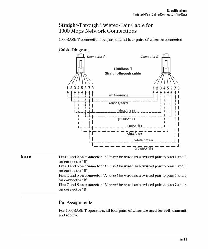
Straight-Through Twisted-Pair Cable for1000 Mbps Network Connections
1000BASE-T connections require that all four pairs of wires be connected.
Cable Diagram
N o t e Pins 1 and 2 on connector “A” must be wired as a twisted pair to pins 1 and 2 on connector “B”.Pins 3 and 6 on connector “A” must be wired as a twisted pair to pins 3 and 6 on connector “B”.Pins 4 and 5 on connector “A” must be wired as a twisted pair to pins 4 and 5 on connector “B”.Pins 7 and 8 on connector “A” must be wired as a twisted pair to pins 7 and 8 on connector “B”.
.
Pin Assignments
For 1000BASE-T operation, all four pairs of wires are used for both transmit and receive.

A-12
SpecificationsTwisted-Pair Cable/Connector Pin-Outs

B-1
B
EMC Regulatory Statements
Regulatory Statements
U.S.A.
FCC Class A
This equipment has been tested and found to comply with the limits for a Class A digital device, pursuant to part 15 of the FCC Rules. These limits are designed to provide reasonable protection against harmful interference when the equipment is operated in a commercial environment. This equipment generates, uses, and can radiate radio frequency energy and, if not installed and used in accordance with the instruction manual, may cause harmful interference to radio communications. Operation of this equipment in a residential area is likely to cause harmful interference in which case the user will be required to correct the interference at his own expense.
You are cautioned that changes or modifications not expressly approved by the party responsible for compliance could void your authority to operate the equipment.
Canada
This product complies with Class A Canadian EMC requirements.
Australia/New Zealand
This product complies with Australia/New Zealand EMC Class A requirements.

B-2
EMC Regulatory StatementsRegulatory Statements
Japan
VCCI Class A
Korea
Taiwan
Index-1
Numerics
10/100BASE-TX portslocation on switch … 1-2
1000Base-T1000Base-T
fiber-optic cable specifications … A-5
A
acoustic specifications … A-2auto MDI/MDI-X operation … A-9, A-11
HP Auto-MDIX feature … A-7
B
back of switchpower connector … 1-6
basic troubleshooting tips … 4-1blinking LEDs
error indications … 4-2, 4-5buttons
Reset button … 1-6
C
cabinetmounting the switch in … 2-9, 2-11
cablesconnecting cables to switch ports … 2-14–2-15infrastructure requirements … 2-6
cables, twisted paircategory 3, 4, 5 … A-7cross-over cable pin-out … A-10MDI-X to MDI connections … A-9, A-11MDI-X to MDI-X connections … A-10pin-outs … A-9, A-11straight-through cable pin-out … A-9, A-11switch-to-computer connection … A-9, A-11switch-to-switch or hub connection … A-10
cables, twisted-pairHP Auto-MDIX feature … A-7wiring rules … A-7
cables, twisted-pair connector pin-outs … A-7cabling infrastructure … 2-6
Clear buttonlocation on switch … 1-2restoring factory default configuration … 1-6,
4-5configuration
restoring factory defaults … 1-6connecting the switch to a power source … 2-13console port
location on switch … 1-2cross-over cable
pin-out … A-10
D
descriptionfront of switch … 1-2LEDs … 1-5switch … 1-1
E
electrical specifications, switch … A-1–A-2environmental specifications, switch … A-2
F
factory default configuration, restoring … 1-6Fault LED
location on switch … 1-2showing error conditions … 4-2
fiber-optic cables1000Base-T … A-5
front of switch … 1-210/100BASE-TX ports … 1-2description … 1-2network ports … 1-4Reset button … 1-6
H
horizontal surfacemounting switch on … 2-12
HP Auto-MDIXfeature description … A-7
Index

Index-2
I
included parts … 2-1installation
connecting the switch to a power source … 2-13horizontal surface mounting … 2-12location considerations … 2-6network cable requirements … 2-6precautions … 2-4rack or cabinet mounting … 2-9, 2-11site preparation … 2-6
L
LEDsbehavior during self test … 2-8descriptions of … 1-5error indications … 4-2, 4-5Fault
showing error conditions … 4-2location on switch … 1-2Power … 1-5
behavior during self test … 2-9location for the switch, considerations … 2-6
M
MDI-X to MDI network cable … A-9, A-11MDI-X to MDI-X network cable … A-10mounting the switch
in a rack or cabinet … 2-9, 2-11precautions … 2-4
on a horizontal surface … 2-12
N
network cablesHP Auto-MDIX feature … A-7required types … 2-6twisted-pair connector pin-outs … A-7twisted-pair, wiring rules … A-7
network devicesconnecting to the switch … 2-14–2-15
network portsconnecting to … 2-14–2-15location on switch … 1-4types of … 1-4
P
parts, included with the switch … 2-1physical specifications, switch … A-1pin-outs
twisted-pair cables … A-7PoE LED patterns … 4-4PoE troubleshooting … 4-4port LEDs
normal operation … 2-9ports
10/100BASE-TX, location on switch … 1-2–1-310/100Base-TX, location on switch … 1-2–1-3connecting to … 2-14–2-15HP Auto-MDIX feature … A-7network connections … 2-14–2-15
power connector … 1-6Power LED … 1-5
behavior during self test … 2-9behaviors … 1-5location on switch … 1-2
power sourceconnecting the switch to … 2-13
Power-over-EthernetPoE power … 1-4
precautionsmounting the switch … 2-4power requirements … 2-4
preparing the installation site … 2-6
R
rackmounting precautions … 2-4mounting the switch in … 2-9, 2-11
Reset buttondescription … 1-6location on switch … 1-2, 1-6restoring factory default configuration … 4-5
resetting the switchlocation of Reset button … 1-6
S
safety and regulatory statements … B-1safety specifications … A-2self test
LED behavior during … 2-8Power LED behavior … 2-9

Index-3
SFPsslot, location on switch … 1-2
slots for SFPslocation on switch … 1-2
specificationsacoustic … A-2electrical … A-1–A-2environmental … A-2physical … A-1safety … A-2
straight-through cablepin-out … A-9, A-11
switchconnecting to a power source … 2-13description … 1-1electrical specifications … A-1–A-2environmental specifications … A-2front panel description … 1-2included parts … 2-1mounting in a rack or cabinet … 2-9, 2-11mounting on horizontal surface … 2-12physical specifications … A-1
switch operationverifying after installation … 2-6
T
tips for troubleshooting … 4-1troubleshooting … 4-1
basic tips … 4-1common network problems … 4-1
twisted-pair cablecross-over cable pin-out … A-10pin-outs … A-7, A-9, A-11straight-through cable pin-out … A-9, A-11switch-to-computer connection … A-9, A-11switch-to-switch or hub connection … A-10
twisted-pair portsHP Auto-MDIX feature … A-7
W
wiring rules for twisted-pair cables … A-7

Index-4

5400zl Switches
Technology for better business outcomes
To learn more, visit www.hp.com/networking
© Copyright 2015 Hewlett-Packard Development Company, L.P.
The information contained herein is subject to change without notice. The only warranties for HP products and services are set forth in the express warranty statements accompanying such products and services. Nothing herein should be construed as constituting an additional warranty. HP will not be liable for technical or editorial errors or omissions contained herein. February 2015
Manual Part Number 5998-5835