howto - rockford fosgate · howto diy distortion meter by eric russell properly setting amplifier...
TRANSCRIPT
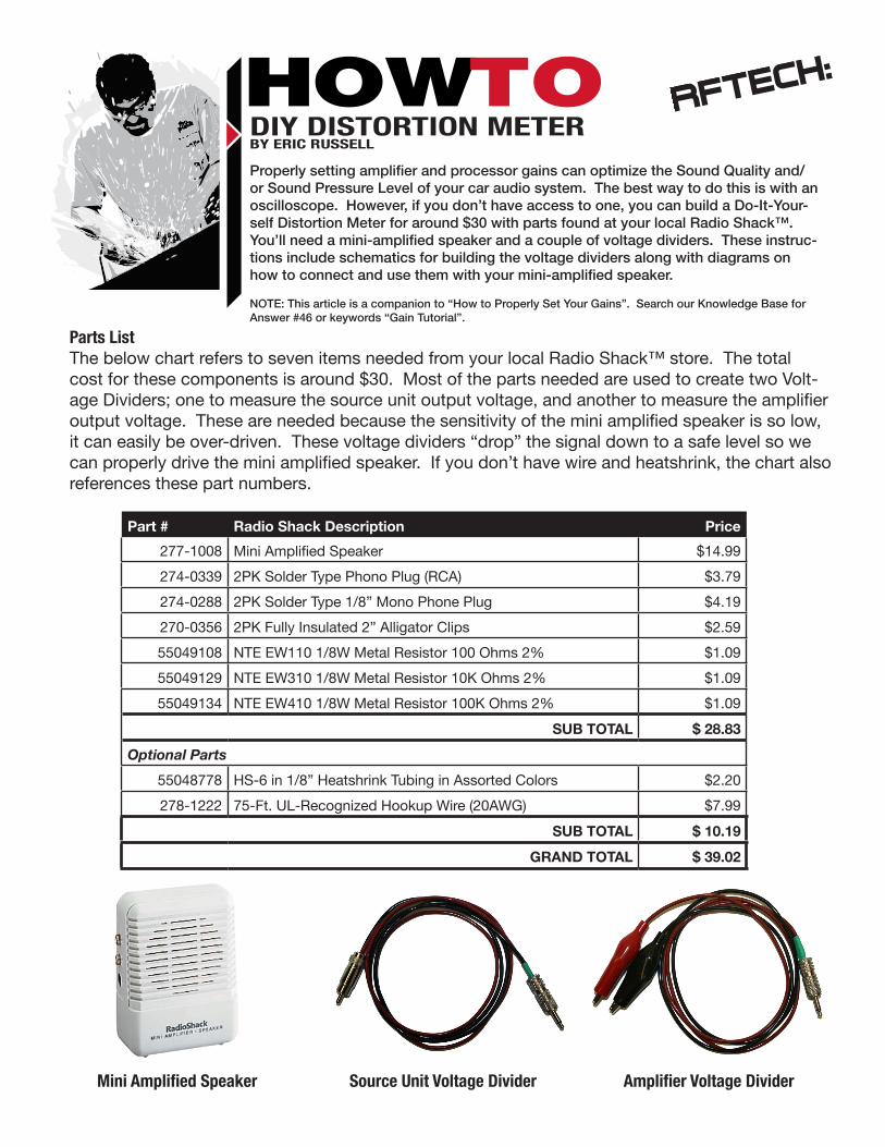
HOWTODIY DISTORTION METERBY ERIC RUSSELL
Properly setting amplifier and processor gains can optimize the Sound Quality and/or Sound Pressure Level of your car audio system. The best way to do this is with an oscilloscope. However, if you don’t have access to one, you can build a Do-It-Your-self Distortion Meter for around $30 with parts found at your local Radio Shack™. You’ll need a mini-amplified speaker and a couple of voltage dividers. These instruc-tions include schematics for building the voltage dividers along with diagrams on how to connect and use them with your mini-amplified speaker.
NOTE: This article is a companion to “How to Properly Set Your Gains”. Search our Knowledge Base for Answer #46 or keywords “Gain Tutorial”.
Parts ListThe below chart refers to seven items needed from your local Radio Shack™ store. The total cost for these components is around $30. Most of the parts needed are used to create two Volt-age Dividers; one to measure the source unit output voltage, and another to measure the amplifier output voltage. These are needed because the sensitivity of the mini amplified speaker is so low, it can easily be over-driven. These voltage dividers “drop” the signal down to a safe level so we can properly drive the mini amplified speaker. If you don’t have wire and heatshrink, the chart also references these part numbers.
Mini Amplified Speaker Source Unit Voltage Divider Amplifier Voltage Divider
Part # Radio Shack Description Price
277-1008 Mini Amplified Speaker $14.99
274-0339 2PK Solder Type Phono Plug (RCA) $3.79
274-0288 2PK Solder Type 1/8” Mono Phone Plug $4.19
270-0356 2PK Fully Insulated 2” Alligator Clips $2.59
55049108 NTE EW110 1/8W Metal Resistor 100 Ohms 2% $1.09
55049129 NTE EW310 1/8W Metal Resistor 10K Ohms 2% $1.09
55049134 NTE EW410 1/8W Metal Resistor 100K Ohms 2% $1.09
SUB TOTAL $ 28.83
Optional Parts
55048778 HS-6 in 1/8” Heatshrink Tubing in Assorted Colors $2.20
278-1222 75-Ft. UL-Recognized Hookup Wire (20AWG) $7.99
SUB TOTAL $ 10.19
GRAND TOTAL $ 39.02
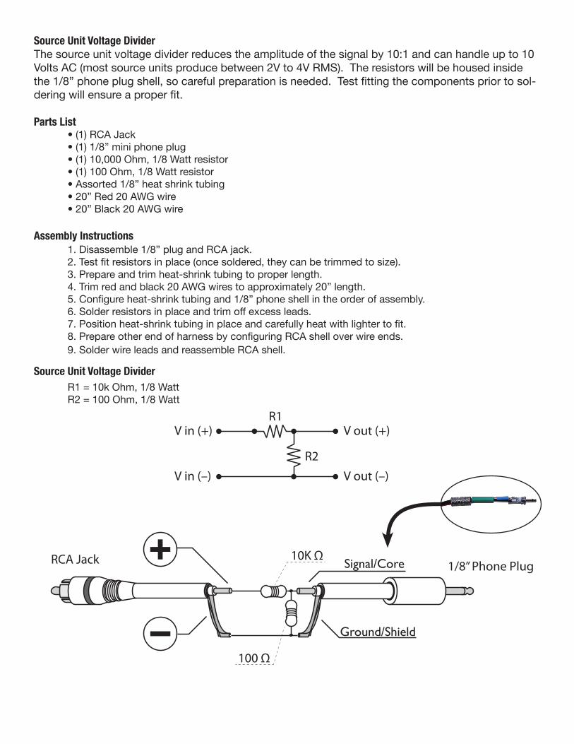
Source Unit Voltage DividerThe source unit voltage divider reduces the amplitude of the signal by 10:1 and can handle up to 10 Volts AC (most source units produce between 2V to 4V RMS). The resistors will be housed inside the 1/8” phone plug shell, so careful preparation is needed. Test fitting the components prior to sol-dering will ensure a proper fit.
Parts List • (1) RCA Jack • (1) 1/8” mini phone plug • (1) 10,000 Ohm, 1/8 Watt resistor • (1) 100 Ohm, 1/8 Watt resistor • Assorted 1/8” heat shrink tubing • 20” Red 20 AWG wire • 20” Black 20 AWG wire
Assembly Instructions 1. Disassemble 1/8” plug and RCA jack. 2. Test fit resistors in place (once soldered, they can be trimmed to size). 3. Prepare and trim heat-shrink tubing to proper length. 4. Trim red and black 20 AWG wires to approximately 20” length. 5. Configure heat-shrink tubing and 1/8” phone shell in the order of assembly. 6. Solder resistors in place and trim off excess leads. 7. Position heat-shrink tubing in place and carefully heat with lighter to fit. 8. Prepare other end of harness by configuring RCA shell over wire ends. 9. Solder wire leads and reassemble RCA shell.
R1 = 10k Ohm, 1/8 Watt R2 = 100 Ohm, 1/8 Watt
Source Unit Voltage Divider
Ground/Shield
Signal/Core
100 Ω
100K Ω
R1
(–)
(+)
R2
V in (+)
V in (–)
V out (+)
V out (–)
R1
R2
V in (+)
V in (–)
V out (+)
V out (–)
1/8” Phone Plug
Ampli�er Voltage Divider
Source Unit Voltage Divider
Alligator Clips
Ground/Shield
Signal/Core
100 Ω
10K ΩRCA Jack 1/8” Phone Plug
Ground/Shield
Signal/Core
100 Ω
100K Ω
R1
(–)
(+)
R2
V in (+)
V in (–)
V out (+)
V out (–)
R1
R2
V in (+)
V in (–)
V out (+)
V out (–)
1/8” Phone Plug
Ampli�er Voltage Divider
Source Unit Voltage Divider
Alligator Clips
Ground/Shield
Signal/Core
100 Ω
10K ΩRCA Jack 1/8” Phone Plug
Amplifier Voltage DividerThe amplifier voltage divider reduces the amplitude of the signal by 1,000:1 and can handle up to 100 Volts AC (that’s a pair of Power T2500-1bdCP amplifiers connected together in bd-SYNC mode). Like the previous method, the resistors will be housed inside the 1/8” phone plug shell, so careful preparation is needed. Test fitting the components prior to soldering will ensure a proper fit.
Parts List • (1) RCA Jack • (1) 1/8” mini phone plug • (1) 100,000 Ohm, 1/8 Watt resistor • (1) 100 Ohm, 1/8 Watt resistor • Assorted 1/8” heat shrink tubing • 20” Red 20 AWG wire • 20” Black 20 AWG wire
Assembly Instructions 1. Disassemble 1/8” plug and Alligator Clips. 2. Test fit resistors in place (once soldered, they can be trimmed to size). 3. Prepare and trim heat-shrink tubing to proper length. 4. Trim red and black 20 AWG wires to approximately 20” length. 5. Configure heat-shrink tubing and 1/8” phone shell in the order of assembly. 6. Solder resistors in place and trim off excess leads. 7. Position heat-shrink tubing in place and carefully heat with lighter to fit. 8. Prepare other end of harness by sliding Alligator Clip sleeves over wire ends. 9. Solder wire leads and reassemble Alligator Clips with protective sleeves.
R1 = 100k Ohm, 1/8 Watt R2 = 100 Ohm, 1/8 Watt
Amplifier Voltage Divider
Ground/Shield
Signal/Core
100 Ω
100K Ω
R1
(–)
(+)
R2
V in (+)
V in (–)
V out (+)
V out (–)
R1
R2
V in (+)
V in (–)
V out (+)
V out (–)
1/8” Phone Plug
Ampli�er Voltage Divider
Source Unit Voltage Divider
Alligator Clips
Ground/Shield
Signal/Core
100 Ω
10K ΩRCA Jack 1/8” Phone Plug
Ground/Shield
Signal/Core
100 Ω
100K Ω
R1
(–)
(+)
R2
V in (+)
V in (–)
V out (+)
V out (–)
R1
R2
V in (+)
V in (–)
V out (+)
V out (–)
1/8” Phone Plug
Ampli�er Voltage Divider
Source Unit Voltage Divider
Alligator Clips
Ground/Shield
Signal/Core
100 Ω
10K ΩRCA Jack 1/8” Phone Plug
RadioShackMINI AMPLIFIER • SPEAKER
IN
9V
EXT
Source Unit Voltage DividerR
L
COMPACT DISC PLAYER WITH DIGITAL TUNER
MODE
PUSH
MENUBAND 1
SCAN
DISP
VOL
DIGITAL AUDIO
COMPACT
RFX8350
4
DOWNRPT
2 3
RDM
5
UPDISC
6
CD CHANGER CONTROLLER
LO/DX
PS MUTE
AS
OPEN
LOUDR SEAT
RadioShackMINI AMPLIFIER • SPEAKER
IN
9V
EXT
Amplifier Voltage Divider
Amplifier Voltage Divider
RadioShackMINI AMPLIFIER • SPEAKER
IN
9V
EXT
RadioShackMINI AMPLIFIER • SPEAKER
IN
9V
EXT
Source Unit Voltage DividerR
L
COMPACT DISC PLAYER WITH DIGITAL TUNER
MODE
PUSH
MENUBAND 1
SCAN
DISP
VOL
DIGITAL AUDIO
COMPACT
RFX8350
4
DOWNRPT
2 3
RDM
5
UPDISC
6
CD CHANGER CONTROLLER
LO/DX
PS MUTE
AS
OPEN
LOUDR SEAT
RadioShackMINI AMPLIFIER • SPEAKER
IN
9V
EXT
Amplifier Voltage Divider
Amplifier Voltage Divider
RadioShackMINI AMPLIFIER • SPEAKER
IN
9V
EXT
©2012 Rockford Corporation, All Rights Reserved
RadioShackMINI AMPLIFIER • SPEAKER
IN
9V
EXT
Source Unit Voltage DividerR
L
COMPACT DISC PLAYER WITH DIGITAL TUNER
MODE
PUSH
MENUBAND 1
SCAN
DISP
VOL
DIGITAL AUDIO
COMPACT
RFX8350
4
DOWNRPT
2 3
RDM
5
UPDISC
6
CD CHANGER CONTROLLER
LO/DX
PS MUTE
AS
OPEN
LOUDR SEAT
RadioShackMINI AMPLIFIER • SPEAKER
IN
9V
EXT
Amplifier Voltage Divider
Amplifier Voltage Divider
RadioShackMINI AMPLIFIER • SPEAKER
IN
9V
EXT
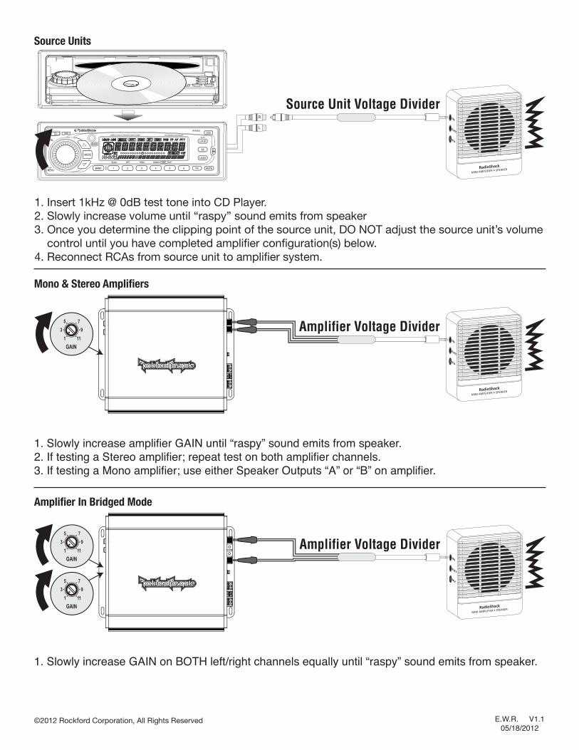
Source Units
Amplifier In Bridged Mode
1. Slowly increase GAIN on BOTH left/right channels equally until “raspy” sound emits from speaker.
1. Slowly increase amplifier GAIN until “raspy” sound emits from speaker.2. If testing a Stereo amplifier; repeat test on both amplifier channels.3. If testing a Mono amplifier; use either Speaker Outputs “A” or “B” on amplifier.
1. Insert 1kHz @ 0dB test tone into CD Player.2. Slowly increase volume until “raspy” sound emits from speaker3. Once you determine the clipping point of the source unit, DO NOT adjust the source unit’s volume control until you have completed amplifier configuration(s) below.4. Reconnect RCAs from source unit to amplifier system.
Mono & Stereo Amplifiers
E.W.R. V1.1 05/18/2012