how to use this install guide - amazon...
TRANSCRIPT

NOTICE: Automotive Data Solutions Inc. (ADS) recommends having this installation performed by a certifi ed technician. Logos and trademarks used here in are the properties of their respective owners.
WARNINGPressing the printer icon or “quick printing” this document will print
all of the guides in this compilation.
Open the Bookmarks menu and find your vehicle OR scroll down until you find the install guide for your vehicle.
Print only the pages for your vehicle using the advanced options in the Print menu.
Install your Maestro RR according to the guide for your vehicle.
HOW TO USE THIS INSTALL GUIDE1
2
3
SELECT VEHICLE PRINT PAGES NEEDED

OPTIONAL ACCESSORIESNone
PROGRAMMED FIRMWAREADS-RR(SI)-HON01-DS
PRODUCTS REQUIREDiDatalink Maestro RR Radio Replacement InterfaceiDatalink Compatible Radio
INSTALL GUIDEACURA CSX
WITh NAV 2006-2011retains steering wheel controls and adds gauges
NOTICE: Automotive Data Solutions Inc. (ADS) recommends having this installation performed by a certified technician. Logos and trademarks used here in are the properties of their respective owners.

ADS-RR(SI)-HON01-DS maestro.idatalink.com
acura csX with naV 2006-2011
Automotive Data Solutions Inc. © 2014 2
WELCOME
NEED hELP?
Congratulations on the purchase of your iDatalink Maestro RR Radio replacement solution. You are now a few simple steps away from enjoying your new car radio with enhanced features. Before starting your installation, please ensure that your iDatalink Maestro module is programmed with the correct fi rmware for your vehicle and that you carefully review the install guide.
Please note that Maestro RR will only retain functionalities that were originally available in the vehicle.
1 866 427-2999
maestro.idatalink.com/supportwww.12voltdata.com/forum
TABLE OF CONTENTS
Wiring Diagram 3
Vehicle Wire Reference Chart 4
Radio Wire Reference Chart 5

ADS-RR(SI)-HON01-DS maestro.idatalink.com
acura csX with naV 2006-2011
Automotive Data Solutions Inc. © 2014 3
A
HG
G
H
3
4 5 6
7 11
21 3
8 9 10 12
8 7 6 51
10 9
17 16 15 14
4 3 2
13
11
1920 18
12
24 2223 21
3 4 5 61 2
17 18 19 20
7 8
21 22 15 16
11 12 13 149 10
23 24 25 26 27 28
10 11 12 13 14 15 16
12
34
56
78
9
06 CANH
14 CANL
A
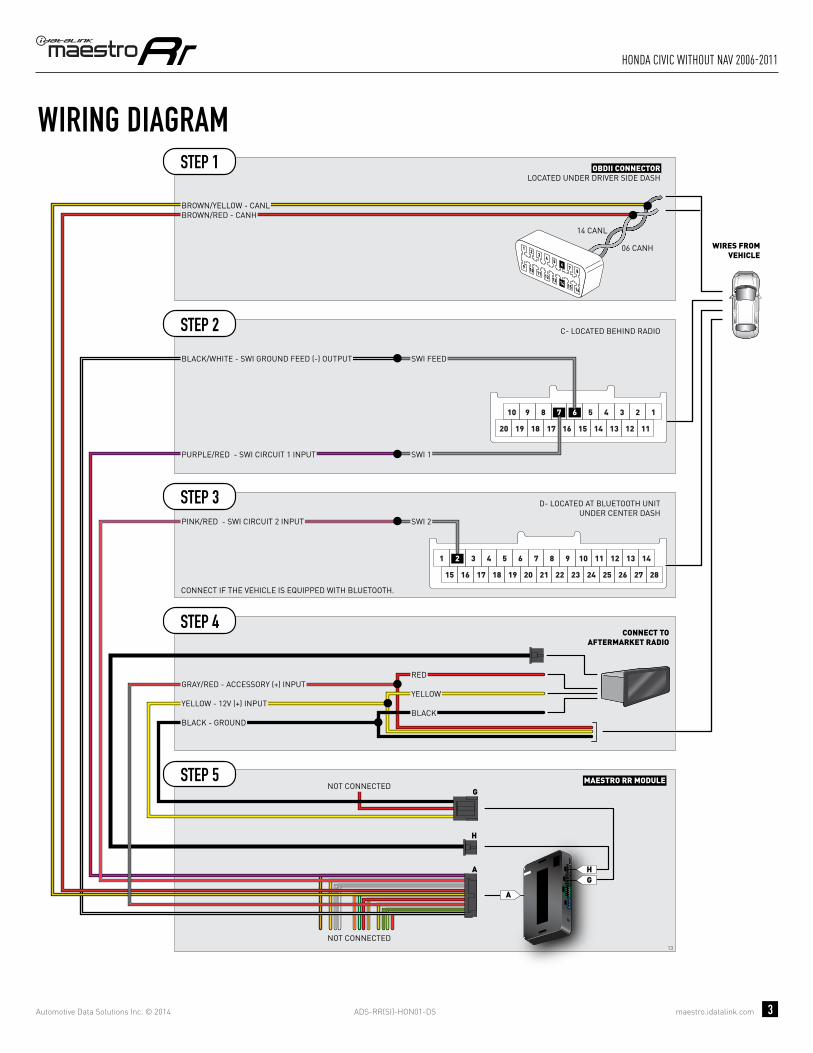
MAESTRO RR MODULENOT CONNECTED
SWI 3SWI 3
E- LOCATED AT NAVIGATION UNIT UNDER CENTER DASH
ORANGE/RED - SWI CIRCUIT 3 INPUT
B- LOCATED BEHIND RADIO
D- LOCATED AT BLUETOOTH UNIT UNDER CENTER DASH
OBDII CONNECTORLOCATED UNDER DRIVER SIDE DASH
CONNECT TOAFTERMARKET RADIO
BROWN/RED - CANH
PURPLE/RED - PURPLE/RED - SWI CIRCUIT 1 INPUT
BLACK/WHITE - BLACK/WHITE - SWI GROUND FEED (-) OUTPUT
SWI 1SWI 1
SWI 2SWI 2
SWI FEEDSWI FEED
BROWN/YELLOW - CANL
WIRES FROMVEHICLE
PINK/RED - PINK/RED - SWI CIRCUIT 2 INPUT
WIRING DIAGRAMSTEP 1
STEP 2
STEP 3
STEP 4
STEP 5
STEP 6
CONNECT IF THE VEHICLE IS EQUIPPED WITH BLUETOOTH.
CONNECT IF THE VEHICLE IS EQUIPPED WITH NAVIGATION.
NOT CONNECTED
YELLOW - 12V (+) INPUT
BLACK - GROUND
GRAY/RED - ACCESSORY (+) INPUT
BLACKBLACK
REDRED
YELLOWYELLOW

ADS-RR(SI)-HON01-DS maestro.idatalink.com
acura csX with naV 2006-2011
Automotive Data Solutions Inc. © 2014 4
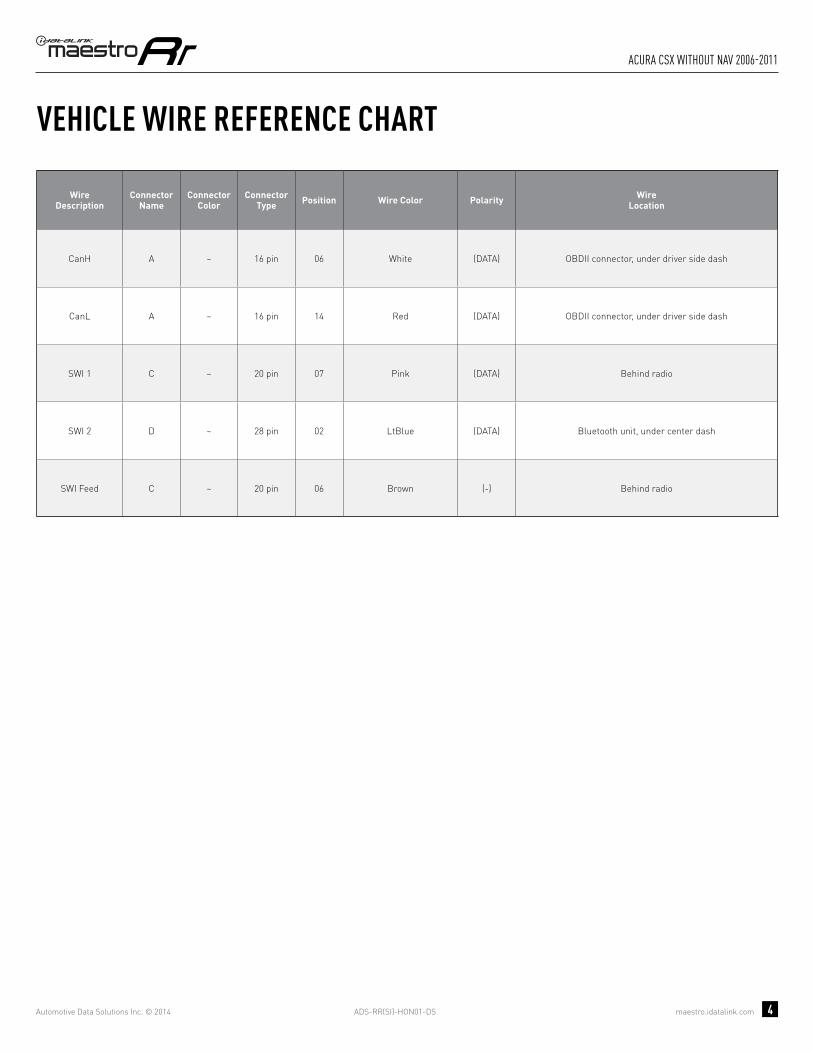
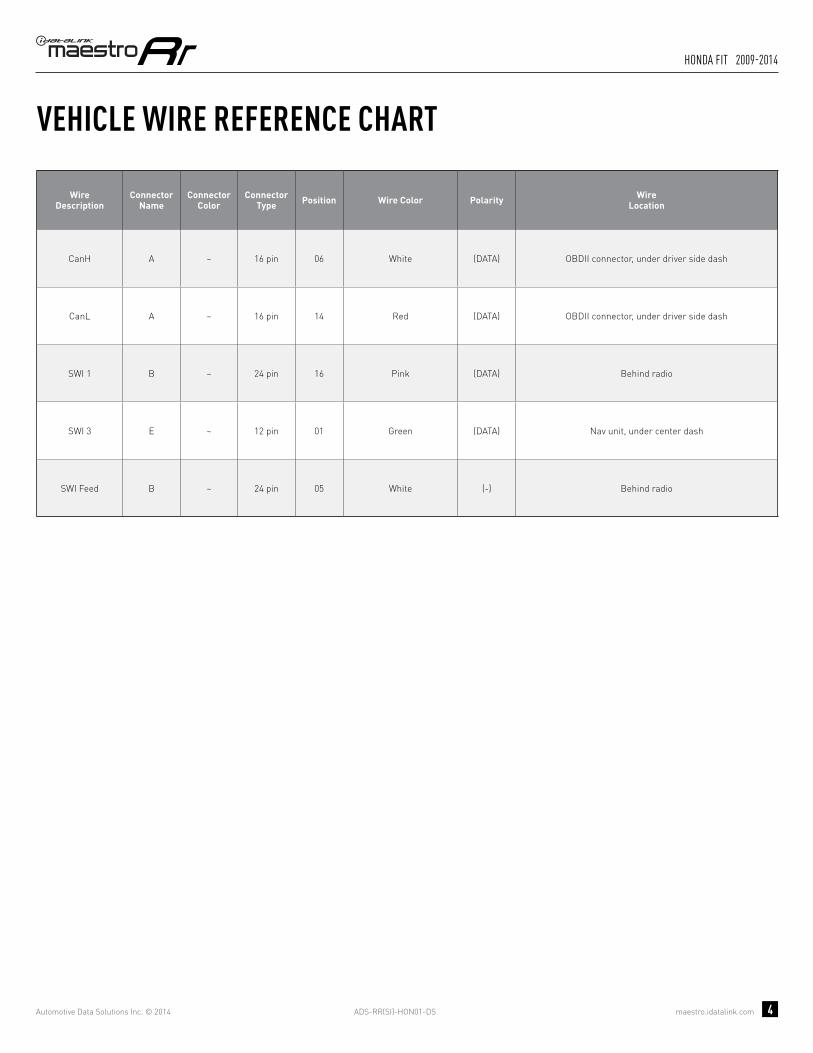
VEHICLE WIRE REFERENCE CHART
WireDescription
Connector Name
ConnectorColor
ConnectorType Position Wire Color Polarity Wire
Location
CanH A ~ 16 pin 06 White (DATA) OBDII connector, under driver side dash
CanL A ~ 16 pin 14 Red (DATA) OBDII connector, under driver side dash
SWI 1 B ~ 24 pin 16 Pink (DATA) Behind radio
SWI 2 D ~ 28 pin 02 Blue (DATA) Bluetooth unit, under center dash
SWI 3 E ~ 12 pin 01 Green (DATA) Nav unit, under center dash
SWI Feed B ~ 24 pin 05 Brown (-) Behind radio

ADS-RR(SI)-HON01-DS maestro.idatalink.com
acura csX with naV 2006-2011
Automotive Data Solutions Inc. © 2014 5
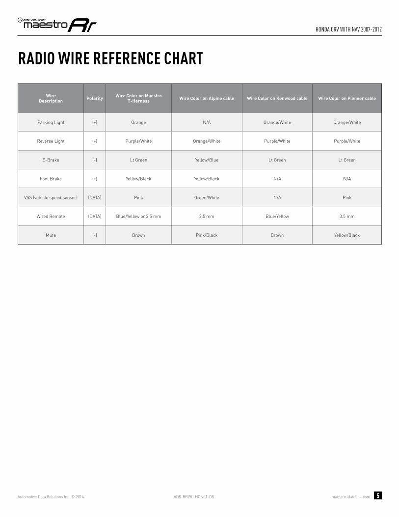
RADIO WIRE REFERENCE CHART
WireDescription Polarity Wire Color on Maestro
T-Harness Wire Color on Alpine cable Wire Color on Kenwood cable Wire Color on Pioneer cable
Parking Light (+) Orange N/A Orange/White Orange/White
Reverse Light (+) Purple/White Orange/White Purple/White Purple/White
E-Brake (-) Lt Green Yellow/Blue Lt Green Lt Green
Foot Brake (+) Yellow/Black Yellow/Black N/A N/A
VSS (vehicle speed sensor) (DATA) Pink Green/White N/A Pink
Wired Remote (DATA) Blue/Yellow or 3.5 mm 3.5 mm Blue/Yellow 3.5 mm
Mute (-) Brown Pink/Black Brown Yellow/Black

OPTIONAL ACCESSORIESNone
PROGRAMMED FIRMWAREADS-RR(SI)-HON01-DS
PRODUCTS REQUIREDiDatalink Maestro RR Radio Replacement InterfaceiDatalink Compatible Radio
INSTALL GUIDEACURA CSX
WIThOUT NAV 2006-2011retains steering wheel controls and adds gauges
NOTICE: Automotive Data Solutions Inc. (ADS) recommends having this installation performed by a certified technician. Logos and trademarks used here in are the properties of their respective owners.

ADS-RR(SI)-HON01-DS maestro.idatalink.com
acura csX without naV 2006-2011
Automotive Data Solutions Inc. © 2014 2
WELCOME
NEED hELP?
Congratulations on the purchase of your iDatalink Maestro RR Radio replacement solution. You are now a few simple steps away from enjoying your new car radio with enhanced features. Before starting your installation, please ensure that your iDatalink Maestro module is programmed with the correct fi rmware for your vehicle and that you carefully review the install guide.
Please note that Maestro RR will only retain functionalities that were originally available in the vehicle.
1 866 427-2999
maestro.idatalink.com/supportwww.12voltdata.com/forum
TABLE OF CONTENTS
Wiring Diagram 3
Vehicle Wire Reference Chart 4
Radio Wire Reference Chart 5

ADS-RR(SI)-HON01-DS maestro.idatalink.com
acura csX without naV 2006-2011
Automotive Data Solutions Inc. © 2014 3
A
HG
G
H
13
A
3 4 5 61 2
17 18 19 20
7 8
21 22 15 16
11 12 13 149 10
23 24 25 26 27 28
10 11 12 13 14 15 16
12
34
56
78
9
06 CANH
14 CANL
8 7 6 5 110 9
17 16 15 14
4 3 2
13 12 111920 18
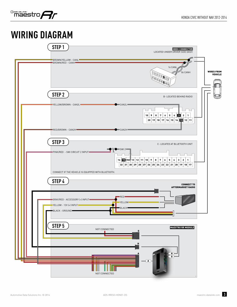
MAESTRO RR MODULENOT CONNECTED
NOT CONNECTED
D- LOCATED AT BLUETOOTH UNITUNDER CENTER DASH
OBDII CONNECTORLOCATED UNDER DRIVER SIDE DASH
CONNECT TOAFTERMARKET RADIO
BROWN/RED - CANH
SWI 2SWI 2
BROWN/YELLOW - CANL
WIRES FROMVEHICLE
PINK/RED - PINK/RED - SWI CIRCUIT 2 INPUT
C- LOCATED BEHIND RADIO
PURPLE/RED - PURPLE/RED - SWI CIRCUIT 1 INPUT
BLACK/WHITE - BLACK/WHITE - SWI GROUND FEED (-) OUTPUT
SWI 1SWI 1
SWI FEEDSWI FEED
WIRING DIAGRAMSTEP 1
STEP 2
STEP 3
STEP 5
STEP 4
CONNECT IF THE VEHICLE IS EQUIPPED WITH BLUETOOTH.
YELLOW - 12V (+) INPUT
BLACK - GROUND
GRAY/RED - ACCESSORY (+) INPUT
BLACKBLACK
REDRED
YELLOWYELLOW
ADS-RR(SI)-HON01-DS maestro.idatalink.com
acura csX without naV 2006-2011
Automotive Data Solutions Inc. © 2014 4
VEHICLE WIRE REFERENCE CHART
WireDescription
Connector Name
ConnectorColor
ConnectorType Position Wire Color Polarity Wire
Location
CanH A ~ 16 pin 06 White (DATA) OBDII connector, under driver side dash
CanL A ~ 16 pin 14 Red (DATA) OBDII connector, under driver side dash
SWI 1 C ~ 20 pin 07 Pink (DATA) Behind radio
SWI 2 D ~ 28 pin 02 LtBlue (DATA) Bluetooth unit, under center dash
SWI Feed C ~ 20 pin 06 Brown (-) Behind radio

ADS-RR(SI)-HON01-DS maestro.idatalink.com
acura csX without naV 2006-2011
Automotive Data Solutions Inc. © 2014 5
RADIO WIRE REFERENCE CHART
WireDescription Polarity Wire Color on Maestro
T-Harness Wire Color on Alpine cable Wire Color on Kenwood cable Wire Color on Pioneer cable
Parking Light (+) Orange N/A Orange/White Orange/White
Reverse Light (+) Purple/White Orange/White Purple/White Purple/White
E-Brake (-) Lt Green Yellow/Blue Lt Green Lt Green
Foot Brake (+) Yellow/Black Yellow/Black N/A N/A
VSS (vehicle speed sensor) (DATA) Pink Green/White N/A Pink
Wired Remote (DATA) Blue/Yellow or 3.5 mm 3.5 mm Blue/Yellow 3.5 mm
Mute (-) Brown Pink/Black Brown Yellow/Black

OPTIONAL ACCESSORIESNone
PROGRAMMED FIRMWAREADS-RR(SI)-HON01-DS
PRODUCTS REQUIREDiDatalink Maestro RR Radio Replacement InterfaceiDatalink Compatible Radio
INSTALL GUIDEhONDA ACCORD
2008-2012retains steering wheel controls and adds gauges
NOTICE: Automotive Data Solutions Inc. (ADS) recommends having this installation performed by a certified technician. Logos and trademarks used here in are the properties of their respective owners.

ADS-RR(SI)-HON01-DS maestro.idatalink.com
honda accord 2008-2012
Automotive Data Solutions Inc. © 2014 2
WELCOME
NEED hELP?
Congratulations on the purchase of your iDatalink Maestro RR Radio replacement solution. You are now a few simple steps away from enjoying your new car radio with enhanced features. Before starting your installation, please ensure that your iDatalink Maestro module is programmed with the correct fi rmware for your vehicle and that you carefully review the install guide.
Please note that Maestro RR will only retain functionalities that were originally available in the vehicle.
1 866 427-2999
maestro.idatalink.com/supportwww.12voltdata.com/forum
TABLE OF CONTENTS
Wiring Diagram 3
Vehicle Wire Reference Chart 4
Radio Wire Reference Chart 5

ADS-RR(SI)-HON01-DS maestro.idatalink.com
honda accord 2008-2012
Automotive Data Solutions Inc. © 2014 3
A
HG
G
H
12
A
8 7 6 51
10 9
17 16 15 14
4 3 2
13
11
1920 18
12
24 2223 21
3 4 5 61 2
17 18 19 20
7 8
21 22 15 16
11 12 13 149 10
23 24 25 26 27 28
10 11 12 13 14 15 16
12
34
56
78
9
06 CANH
14 CANL
MAESTRO RR MODULENOT CONNECTED
NOT CONNECTED
B- LOCATED BEHIND RADIO
D- LOCATED AT BLUETOOTH UNITUNDER CENTER DASH
OBDII CONNECTORLOCATED UNDER DRIVER SIDE DASH
CONNECT TOAFTERMARKET RADIO
BROWN/RED - CANH
PURPLE/RED - PURPLE/RED - SWI CIRCUIT 1 INPUT
BLACK/WHITE - BLACK/WHITE - SWI GROUND FEED (-) OUTPUT
SWI 1SWI 1
SWI 2SWI 2
SWI FEEDSWI FEED
BROWN/YELLOW - CANL
WIRES FROMVEHICLE
PINK/RED - PINK/RED - SWI CIRCUIT 2 INPUT
WIRING DIAGRAMSTEP 1
STEP 2
STEP 3
STEP 5
STEP 4
CONNECT IF THE VEHICLE IS EQUIPPED WITH BLUETOOTH.
YELLOW - 12V (+) INPUT
BLACK - GROUND
GRAY/RED - ACCESSORY (+) INPUT
BLACKBLACK
REDRED
YELLOWYELLOW

ADS-RR(SI)-HON01-DS maestro.idatalink.com
honda accord 2008-2012
Automotive Data Solutions Inc. © 2014 4
VEHICLE WIRE REFERENCE CHART
WireDescription
Connector Name
ConnectorColor
ConnectorType Position Wire Color Polarity Wire
Location
CanH A ~ 16 pin 06 White (DATA) OBDII connector, under driver side dash
CanL A ~ 16 pin 14 Red (DATA) OBDII connector, under driver side dash
SWI 1 B ~ 24 pin 16 Pink (DATA) Behind radio
SWI 2 D ~ 28 pin 02 LtBlue (DATA) Bluetooth unit, under center dash
SWI Feed B ~ 24 pin 05 Brown (-) Behind radio

ADS-RR(SI)-HON01-DS maestro.idatalink.com
honda accord 2008-2012
Automotive Data Solutions Inc. © 2014 5
RADIO WIRE REFERENCE CHART
WireDescription Polarity Wire Color on Maestro
T-Harness Wire Color on Alpine cable Wire Color on Kenwood cable Wire Color on Pioneer cable
Parking Light (+) Orange N/A Orange/White Orange/White
Reverse Light (+) Purple/White Orange/White Purple/White Purple/White
E-Brake (-) Lt Green Yellow/Blue Lt Green Lt Green
Foot Brake (+) Yellow/Black Yellow/Black N/A N/A
VSS (vehicle speed sensor) (DATA) Pink Green/White N/A Pink
Wired Remote (DATA) Blue/Yellow or 3.5 mm 3.5 mm Blue/Yellow 3.5 mm
Mute (-) Brown Pink/Black Brown Yellow/Black

OPTIONAL ACCESSORIESNone
PROGRAMMED FIRMWAREADS-RR(SI)-HON01-DS
PRODUCTS REQUIREDiDatalink Maestro RR Radio Replacement InterfaceiDatalink Compatible Radio
INSTALL GUIDEhONDA ACCORD CROSSTOUR
2010-2012retains steering wheel controls and adds gauges
NOTICE: Automotive Data Solutions Inc. (ADS) recommends having this installation performed by a certified technician. Logos and trademarks used here in are the properties of their respective owners.

ADS-RR(SI)-HON01-DS maestro.idatalink.com
honda accord crosstour 2010-2012
Automotive Data Solutions Inc. © 2014 2
WELCOME
NEED hELP?
Congratulations on the purchase of your iDatalink Maestro RR Radio replacement solution. You are now a few simple steps away from enjoying your new car radio with enhanced features. Before starting your installation, please ensure that your iDatalink Maestro module is programmed with the correct fi rmware for your vehicle and that you carefully review the install guide.
Please note that Maestro RR will only retain functionalities that were originally available in the vehicle.
1 866 427-2999
maestro.idatalink.com/supportwww.12voltdata.com/forum
TABLE OF CONTENTS
Wiring Diagram 3
Vehicle Wire Reference Chart 4
Radio Wire Reference Chart 5

ADS-RR(SI)-HON01-DS maestro.idatalink.com
honda accord crosstour 2010-2012
Automotive Data Solutions Inc. © 2014 3
A
HG
G
H
12
A
8 7 6 51
10 9
17 16 15 14
4 3 2
13
11
1920 18
12
24 2223 21
3 4 5 61 2
17 18 19 20
7 8
21 22 15 16
11 12 13 149 10
23 24 25 26 27 28
10 11 12 13 14 15 16
12
34
56
78
9
06 CANH
14 CANL
MAESTRO RR MODULENOT CONNECTED
NOT CONNECTED
B- LOCATED BEHIND RADIO
D- LOCATED AT BLUETOOTH UNITUNDER CENTER DASH
OBDII CONNECTORLOCATED UNDER DRIVER SIDE DASH
CONNECT TOAFTERMARKET RADIO
BROWN/RED - CANH
PURPLE/RED - PURPLE/RED - SWI CIRCUIT 1 INPUT
BLACK/WHITE - BLACK/WHITE - SWI GROUND FEED (-) OUTPUT
SWI 1SWI 1
SWI 2SWI 2
SWI FEEDSWI FEED
BROWN/YELLOW - CANL
WIRES FROMVEHICLE
PINK/RED - PINK/RED - SWI CIRCUIT 2 INPUT
WIRING DIAGRAMSTEP 1
STEP 2
STEP 3
STEP 5
STEP 4
CONNECT IF THE VEHICLE IS EQUIPPED WITH BLUETOOTH.
YELLOW - 12V (+) INPUT
BLACK - GROUND
GRAY/RED - ACCESSORY (+) INPUT
BLACKBLACK
REDRED
YELLOWYELLOW

ADS-RR(SI)-HON01-DS maestro.idatalink.com
honda accord crosstour 2010-2012
Automotive Data Solutions Inc. © 2014 4
VEHICLE WIRE REFERENCE CHART
WireDescription
Connector Name
ConnectorColor
ConnectorType Position Wire Color Polarity Wire
Location
CanH A ~ 16 pin 06 White (DATA) OBDII connector, under driver side dash
CanL A ~ 16 pin 14 Red (DATA) OBDII connector, under driver side dash
SWI 1 B ~ 24 pin 16 Pink (DATA) Behind radio
SWI 2 D ~ 28 pin 02 LtBlue (DATA) Bluetooth unit, under center dash
SWI Feed B ~ 24 pin 05 Brown (-) Behind radio

ADS-RR(SI)-HON01-DS maestro.idatalink.com
honda accord crosstour 2010-2012
Automotive Data Solutions Inc. © 2014 5
RADIO WIRE REFERENCE CHART
WireDescription Polarity Wire Color on Maestro
T-Harness Wire Color on Alpine cable Wire Color on Kenwood cable Wire Color on Pioneer cable
Parking Light (+) Orange N/A Orange/White Orange/White
Reverse Light (+) Purple/White Orange/White Purple/White Purple/White
E-Brake (-) Lt Green Yellow/Blue Lt Green Lt Green
Foot Brake (+) Yellow/Black Yellow/Black N/A N/A
VSS (vehicle speed sensor) (DATA) Pink Green/White N/A Pink
Wired Remote (DATA) Blue/Yellow or 3.5 mm 3.5 mm Blue/Yellow 3.5 mm
Mute (-) Brown Pink/Black Brown Yellow/Black

OPTIONAL ACCESSORIESNone
PROGRAMMED FIRMWAREADS-RR(SI)-HON01-DS
PRODUCTS REQUIREDiDatalink Maestro RR Radio Replacement InterfaceiDatalink Compatible Radio
INSTALL GUIDEhONDA CRV
WITh NAV 2007-2012retains steering wheel controls and adds gauges
NOTICE: Automotive Data Solutions Inc. (ADS) recommends having this installation performed by a certified technician. Logos and trademarks used here in are the properties of their respective owners.

ADS-RR(SI)-HON01-DS maestro.idatalink.com
honda crV with naV 2007-2012
Automotive Data Solutions Inc. © 2014 2
WELCOME
NEED hELP?
Congratulations on the purchase of your iDatalink Maestro RR Radio replacement solution. You are now a few simple steps away from enjoying your new car radio with enhanced features. Before starting your installation, please ensure that your iDatalink Maestro module is programmed with the correct fi rmware for your vehicle and that you carefully review the install guide.
Please note that Maestro RR will only retain functionalities that were originally available in the vehicle.
1 866 427-2999
maestro.idatalink.com/supportwww.12voltdata.com/forum
TABLE OF CONTENTS
Wiring Diagram 3
Vehicle Wire Reference Chart 4
Radio Wire Reference Chart 5

ADS-RR(SI)-HON01-DS maestro.idatalink.com
honda crV with naV 2007-2012
Automotive Data Solutions Inc. © 2014 3
A
HG
G
H
4
A
4 5 6
7 11
21 3
8 9 10 12
8 7 6 51
10 9
17 16 15 14
4 3 2
13
11
1920 18
12
24 2223 21
3 4 5 61 2
17 18 19 20
7 8
21 22 15 16
11 12 13 149 10
23 24 25 26 27 28
10 11 12 13 14 15 16
12
34
56
78
9
07 CANH
14 CANL
MAESTRO RR MODULENOT CONNECTED
NOT CONNECTED
SWI 3SWI 3
E- LOCATED AT NAVIGATION UNIT UNDER CENTER DASH
ORANGE/RED - SWI CIRCUIT 3 INPUT
B- LOCATED BEHIND RADIO
D- LOCATED AT BLUETOOTH UNIT UNDER CENTER DASH
OBDII CONNECTORLOCATED UNDER DRIVER SIDE DASH
CONNECT TOAFTERMARKET RADIO
BROWN/RED - CANH
PURPLE/RED - PURPLE/RED - SWI CIRCUIT 1 INPUT
BLACK/WHITE - BLACK/WHITE - SWI GROUND FEED (-) OUTPUT
SWI 1SWI 1
SWI 2SWI 2
SWI FEEDSWI FEED
BROWN/YELLOW - CANL
WIRES FROMVEHICLE
PINK/RED - PINK/RED - SWI CIRCUIT 2 INPUT
WIRING DIAGRAMSTEP 1
STEP 2
STEP 3
STEP 4
STEP 5
STEP 6
CONNECT IF THE VEHICLE IS EQUIPPED WITH BLUETOOTH.
CONNECT IF THE VEHICLE IS EQUIPPED WITH NAVIGATION.
YELLOW - 12V (+) INPUT
BLACK - GROUND
GRAY/RED - ACCESSORY (+) INPUT
BLACKBLACK
REDRED
YELLOWYELLOW

ADS-RR(SI)-HON01-DS maestro.idatalink.com
honda crV with naV 2007-2012
Automotive Data Solutions Inc. © 2014 4
VEHICLE WIRE REFERENCE CHART
WireDescription
Connector Name
ConnectorColor
ConnectorType Position Wire Color Polarity Wire
Location
CanH A ~ 16 pin 07 White (DATA) OBDII connector, under driver side dash
CanL A ~ 16 pin 14 Red (DATA) OBDII connector, under driver side dash
SWI 1 B ~ 24 pin 16 Pink (DATA) Behind radio
SWI 2 D ~ 28 pin 02 Blue (DATA) Bluetooth unit, under center dash
SWI 3 E ~ 12 pin 01 Green (DATA) Nav unit, under center dash
SWI Feed B ~ 24 pin 05 Brown (-) Behind radio
ADS-RR(SI)-HON01-DS maestro.idatalink.com
honda crV with naV 2007-2012
Automotive Data Solutions Inc. © 2014 5
RADIO WIRE REFERENCE CHART
WireDescription Polarity Wire Color on Maestro
T-Harness Wire Color on Alpine cable Wire Color on Kenwood cable Wire Color on Pioneer cable
Parking Light (+) Orange N/A Orange/White Orange/White
Reverse Light (+) Purple/White Orange/White Purple/White Purple/White
E-Brake (-) Lt Green Yellow/Blue Lt Green Lt Green
Foot Brake (+) Yellow/Black Yellow/Black N/A N/A
VSS (vehicle speed sensor) (DATA) Pink Green/White N/A Pink
Wired Remote (DATA) Blue/Yellow or 3.5 mm 3.5 mm Blue/Yellow 3.5 mm
Mute (-) Brown Pink/Black Brown Yellow/Black

OPTIONAL ACCESSORIESNone
PROGRAMMED FIRMWAREADS-RR(SI)-HON01-DS
PRODUCTS REQUIREDiDatalink Maestro RR Radio Replacement InterfaceiDatalink Compatible Radio
INSTALL GUIDEhONDA CRV
WITh NAV 2013-2014retains steering wheel controls and adds gauges
NOTICE: Automotive Data Solutions Inc. (ADS) recommends having this installation performed by a certified technician. Logos and trademarks used here in are the properties of their respective owners.

ADS-RR(SI)-HON01-DS maestro.idatalink.com
honda crV with naV 2013-2014
Automotive Data Solutions Inc. © 2014 2
WELCOME
NEED hELP?
Congratulations on the purchase of your iDatalink Maestro RR Radio replacement solution. You are now a few simple steps away from enjoying your new car radio with enhanced features. Before starting your installation, please ensure that your iDatalink Maestro module is programmed with the correct fi rmware for your vehicle and that you carefully review the install guide.
Please note that Maestro RR will only retain functionalities that were originally available in the vehicle.
1 866 427-2999
maestro.idatalink.com/supportwww.12voltdata.com/forum
TABLE OF CONTENTS
Wiring Diagram 3
Vehicle Wire Reference Chart 4
Radio Wire Reference Chart 5

ADS-RR(SI)-HON01-DS maestro.idatalink.com
honda crV with naV 2013-2014
Automotive Data Solutions Inc. © 2014 3
A
HG
A
G
H
2
8 7 6 5 110 9
17 16 15 14
4 3 2
13 12 111920 18
6 58 714 1316 15 2 14 310 911
18 1720 19212223
12
25 2427 262829303132
10 11 12 13 14 15 16
12
34
56
78
9
06 CANH
14 CANL
MAESTRO RR MODULENOT CONNECTED
B- LOCATED BEHIND RADIO
C- LOCATED AT BLUETOOTH UNIT
OBDII CONNECTORLOCATED UNDER DRIVER SIDE DASH
CONNECT TOAFTERMARKET RADIO
BROWN/RED - CANH
PINK/RED - PINK/RED - SWI CIRCUIT 2 INPUT
YELLOW/BROWN - YELLOW/BROWN - CAN2L
SWI 2SWI 2
CAN2LCAN2L
RED/BROWN - RED/BROWN - CAN2H CAN2HCAN2H
BROWN/YELLOW - CANL
WIRES FROMVEHICLE
YELLOW - 12V (+) INPUT
BLACK - GROUND
GRAY/RED - ACCESSORY (+) INPUT
WIRING DIAGRAMSTEP 1
STEP 2
STEP 3
STEP 5
STEP 4
CONNECT IF THE VEHICLE IS EQUIPPED WITH BLUETOOTH.
NOT CONNECTED
BLACKBLACK
REDRED
YELLOWYELLOW

ADS-RR(SI)-HON01-DS maestro.idatalink.com
honda crV with naV 2013-2014
Automotive Data Solutions Inc. © 2014 4
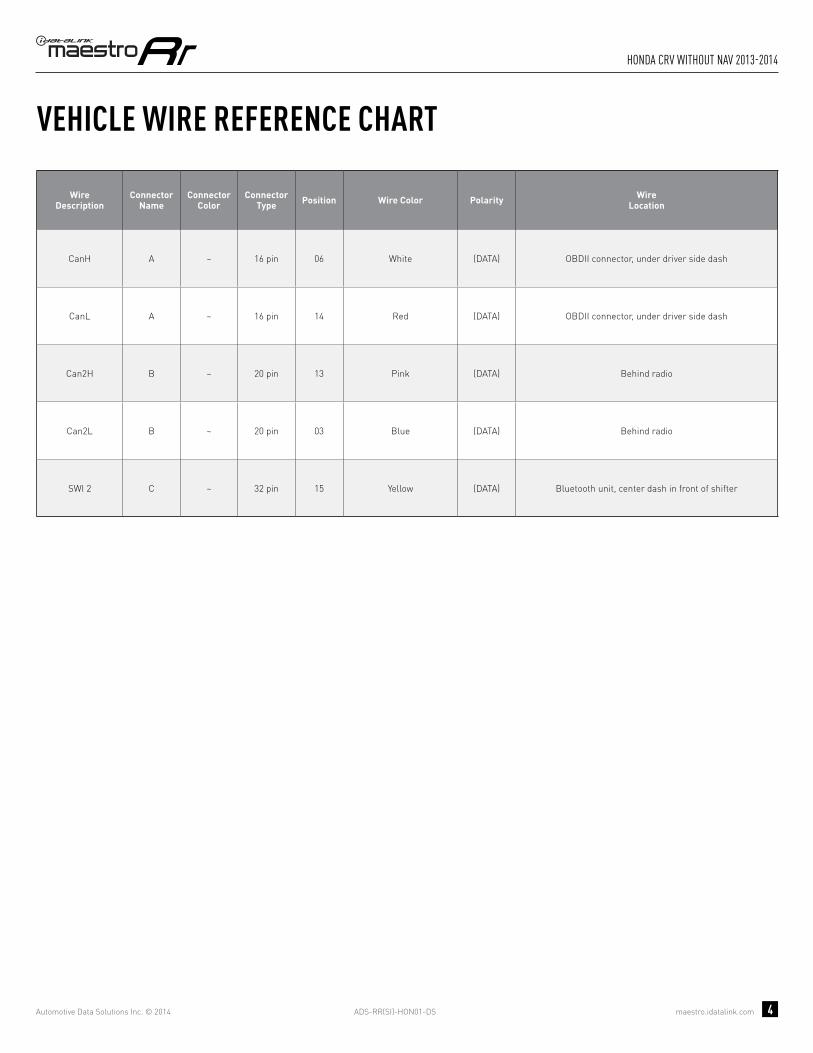
VEHICLE WIRE REFERENCE CHART
WireDescription
Connector Name
ConnectorColor
ConnectorType Position Wire Color Polarity Wire
Location
CanH A ~ 16 pin 06 White (DATA) OBDII connector, under driver side dash
CanL A ~ 16 pin 14 Red (DATA) OBDII connector, under driver side dash
Can2H B ~ 20 pin 01 Pink (DATA) Behind radio
Can2L B ~ 20 pin 09 Blue (DATA) Behind radio
SWI 2 C ~ 32 pin 15 Yellow (DATA) Bluetooth unit, center dash in front of shifter

ADS-RR(SI)-HON01-DS maestro.idatalink.com
honda crV with naV 2013-2014
Automotive Data Solutions Inc. © 2014 5
RADIO WIRE REFERENCE CHART
WireDescription Polarity Wire Color on Maestro
T-Harness Wire Color on Alpine cable Wire Color on Kenwood cable Wire Color on Pioneer cable
Parking Light (+) Orange N/A Orange/White Orange/White
Reverse Light (+) Purple/White Orange/White Purple/White Purple/White
E-Brake (-) Lt Green Yellow/Blue Lt Green Lt Green
Foot Brake (+) Yellow/Black Yellow/Black N/A N/A
VSS (vehicle speed sensor) (DATA) Pink Green/White N/A Pink
Wired Remote (DATA) Blue/Yellow or 3.5 mm 3.5 mm Blue/Yellow 3.5 mm
Mute (-) Brown Pink/Black Brown Yellow/Black

OPTIONAL ACCESSORIESNone
PROGRAMMED FIRMWAREADS-RR(SI)-HON01-DS
PRODUCTS REQUIREDiDatalink Maestro RR Radio Replacement InterfaceiDatalink Compatible Radio
INSTALL GUIDEhONDA CRV
WIThOUT NAV 2007-2012retains steering wheel controls and adds gauges
NOTICE: Automotive Data Solutions Inc. (ADS) recommends having this installation performed by a certified technician. Logos and trademarks used here in are the properties of their respective owners.

ADS-RR(SI)-HON01-DS maestro.idatalink.com
honda crV without naV 2007-2012
Automotive Data Solutions Inc. © 2014 2
WELCOME
NEED hELP?
Congratulations on the purchase of your iDatalink Maestro RR Radio replacement solution. You are now a few simple steps away from enjoying your new car radio with enhanced features. Before starting your installation, please ensure that your iDatalink Maestro module is programmed with the correct fi rmware for your vehicle and that you carefully review the install guide.
Please note that Maestro RR will only retain functionalities that were originally available in the vehicle.
1 866 427-2999
maestro.idatalink.com/supportwww.12voltdata.com/forum
TABLE OF CONTENTS
Wiring Diagram 3
Vehicle Wire Reference Chart 4
Radio Wire Reference Chart 5

ADS-RR(SI)-HON01-DS maestro.idatalink.com
honda crV without naV 2007-2012
Automotive Data Solutions Inc. © 2014 3
A
HG
G
H
13
A
3 4 5 61 2
17 18 19 20
7 8
21 22 15 16
11 12 13 149 10
23 24 25 26 27 28
10 11 12 13 14 15 16
12
34
56
78
9
06 CANH
14 CANL
8 7 6 5 110 9
17 16 15 14
4 3 2
13 12 111920 18
MAESTRO RR MODULENOT CONNECTED
NOT CONNECTED
D- LOCATED AT BLUETOOTH UNITUNDER CENTER DASH
OBDII CONNECTORLOCATED UNDER DRIVER SIDE DASH
CONNECT TOAFTERMARKET RADIO
BROWN/RED - CANH
SWI 2SWI 2
BROWN/YELLOW - CANL
WIRES FROMVEHICLE
PINK/RED - PINK/RED - SWI CIRCUIT 2 INPUT
C- LOCATED BEHIND RADIO
PURPLE/RED - PURPLE/RED - SWI CIRCUIT 1 INPUT
BLACK/WHITE - BLACK/WHITE - SWI GROUND FEED (-) OUTPUT
SWI 1SWI 1
SWI FEEDSWI FEED
WIRING DIAGRAMSTEP 1
STEP 2
STEP 3
STEP 5
STEP 4
CONNECT IF THE VEHICLE IS EQUIPPED WITH BLUETOOTH.
YELLOW - 12V (+) INPUT
BLACK - GROUND
GRAY/RED - ACCESSORY (+) INPUT
BLACKBLACK
REDRED
YELLOWYELLOW

ADS-RR(SI)-HON01-DS maestro.idatalink.com
honda crV without naV 2007-2012
Automotive Data Solutions Inc. © 2014 4
VEHICLE WIRE REFERENCE CHART
WireDescription
Connector Name
ConnectorColor
ConnectorType Position Wire Color Polarity Wire
Location
CanH A ~ 16 pin 06 White (DATA) OBDII connector, under driver side dash
CanL A ~ 16 pin 14 Red (DATA) OBDII connector, under driver side dash
SWI 1 C ~ 20 pin 07 Pink (DATA) Behind radio
SWI 2 D ~ 28 pin 02 LtBlue (DATA) Bluetooth unit, under center dash
SWI Feed C ~ 20 pin 06 Brown (-) Behind radio

ADS-RR(SI)-HON01-DS maestro.idatalink.com
honda crV without naV 2007-2012
Automotive Data Solutions Inc. © 2014 5
RADIO WIRE REFERENCE CHART
WireDescription Polarity Wire Color on Maestro
T-Harness Wire Color on Alpine cable Wire Color on Kenwood cable Wire Color on Pioneer cable
Parking Light (+) Orange N/A Orange/White Orange/White
Reverse Light (+) Purple/White Orange/White Purple/White Purple/White
E-Brake (-) Lt Green Yellow/Blue Lt Green Lt Green
Foot Brake (+) Yellow/Black Yellow/Black N/A N/A
VSS (vehicle speed sensor) (DATA) Pink Green/White N/A Pink
Wired Remote (DATA) Blue/Yellow or 3.5 mm 3.5 mm Blue/Yellow 3.5 mm
Mute (-) Brown Pink/Black Brown Yellow/Black

OPTIONAL ACCESSORIESNone
PROGRAMMED FIRMWAREADS-RR(SI)-HON01-DS
PRODUCTS REQUIREDiDatalink Maestro RR Radio Replacement InterfaceiDatalink Compatible Radio
INSTALL GUIDEhONDA CRV
WIThOUT NAV 2013-2014retains steering wheel controls and adds gauges
NOTICE: Automotive Data Solutions Inc. (ADS) recommends having this installation performed by a certified technician. Logos and trademarks used here in are the properties of their respective owners.
ADS-RR(SI)-HON01-DS maestro.idatalink.com
honda crV without naV 2013-2014
Automotive Data Solutions Inc. © 2014 2
WELCOME
NEED hELP?
Congratulations on the purchase of your iDatalink Maestro RR Radio replacement solution. You are now a few simple steps away from enjoying your new car radio with enhanced features. Before starting your installation, please ensure that your iDatalink Maestro module is programmed with the correct fi rmware for your vehicle and that you carefully review the install guide.
Please note that Maestro RR will only retain functionalities that were originally available in the vehicle.
1 866 427-2999
maestro.idatalink.com/supportwww.12voltdata.com/forum
TABLE OF CONTENTS
Wiring Diagram 3
Vehicle Wire Reference Chart 4
Radio Wire Reference Chart 5

ADS-RR(SI)-HON01-DS maestro.idatalink.com
honda crV without naV 2013-2014
Automotive Data Solutions Inc. © 2014 3
8 7 6 5 110 9
17 16 15 14
4 3 2
13 12 111920 18
6 58 714 1316 15 2 14 310 911
18 1720 19212223
12
25 2427 262829303132
A
HG
G
H
10 11 12 13 14 15 16
12
34
56
78
9
06 CANH
14 CANL
1
A
B- LOCATED BEHIND RADIO
C- LOCATED AT BLUETOOTH UNIT
OBDII CONNECTORLOCATED UNDER DRIVER SIDE DASH
MAESTRO RR MODULE
CONNECT TOAFTERMARKET RADIO
BROWN/RED - CANH
YELLOW/BROWN - YELLOW/BROWN - CAN2L
SWI 2SWI 2
CAN2LCAN2L
RED/BROWN - RED/BROWN - CAN2H CAN2HCAN2H
BROWN/YELLOW - CANL
WIRES FROMVEHICLE
YELLOW - 12V (+) INPUT
BLACK - GROUND
GRAY/RED - ACCESSORY (+) INPUT
WIRING DIAGRAMSTEP 1
STEP 2
STEP 3
STEP 5
STEP 4
CONNECT IF THE VEHICLE IS EQUIPPED WITH BLUETOOTH.
NOT CONNECTED
NOT CONNECTED
BLACKBLACK
REDRED
YELLOWYELLOW
PINK/RED - PINK/RED - SWI CIRCUIT 2 INPUT
ADS-RR(SI)-HON01-DS maestro.idatalink.com
honda crV without naV 2013-2014
Automotive Data Solutions Inc. © 2014 4
VEHICLE WIRE REFERENCE CHART
WireDescription
Connector Name
ConnectorColor
ConnectorType Position Wire Color Polarity Wire
Location
CanH A ~ 16 pin 06 White (DATA) OBDII connector, under driver side dash
CanL A ~ 16 pin 14 Red (DATA) OBDII connector, under driver side dash
Can2H B ~ 20 pin 13 Pink (DATA) Behind radio
Can2L B ~ 20 pin 03 Blue (DATA) Behind radio
SWI 2 C ~ 32 pin 15 Yellow (DATA) Bluetooth unit, center dash in front of shifter

ADS-RR(SI)-HON01-DS maestro.idatalink.com
honda crV without naV 2013-2014
Automotive Data Solutions Inc. © 2014 5
RADIO WIRE REFERENCE CHART
WireDescription Polarity Wire Color on Maestro
T-Harness Wire Color on Alpine cable Wire Color on Kenwood cable Wire Color on Pioneer cable
Parking Light (+) Orange N/A Orange/White Orange/White
Reverse Light (+) Purple/White Orange/White Purple/White Purple/White
E-Brake (-) Lt Green Yellow/Blue Lt Green Lt Green
Foot Brake (+) Yellow/Black Yellow/Black N/A N/A
VSS (vehicle speed sensor) (DATA) Pink Green/White N/A Pink
Wired Remote (DATA) Blue/Yellow or 3.5 mm 3.5 mm Blue/Yellow 3.5 mm
Mute (-) Brown Pink/Black Brown Yellow/Black

OPTIONAL ACCESSORIESNone
PROGRAMMED FIRMWAREADS-RR(SI)-HON01-DS
PRODUCTS REQUIREDiDatalink Maestro RR Radio Replacement InterfaceiDatalink Compatible Radio
INSTALL GUIDEhONDA CRZ 2011-2014
retains steering wheel controls and adds gauges
NOTICE: Automotive Data Solutions Inc. (ADS) recommends having this installation performed by a certified technician. Logos and trademarks used here in are the properties of their respective owners.

ADS-RR(SI)-HON01-DS maestro.idatalink.com
honda crZ 2011-2014
Automotive Data Solutions Inc. © 2014 2
WELCOME
NEED hELP?
Congratulations on the purchase of your iDatalink Maestro RR Radio replacement solution. You are now a few simple steps away from enjoying your new car radio with enhanced features. Before starting your installation, please ensure that your iDatalink Maestro module is programmed with the correct fi rmware for your vehicle and that you carefully review the install guide.
Please note that Maestro RR will only retain functionalities that were originally available in the vehicle.
1 866 427-2999
maestro.idatalink.com/supportwww.12voltdata.com/forum
TABLE OF CONTENTS
Wiring Diagram 3
Vehicle Wire Reference Chart 4
Radio Wire Reference Chart 5

ADS-RR(SI)-HON01-DS maestro.idatalink.com
honda crZ 2011-2014
Automotive Data Solutions Inc. © 2014 3
A
HG
G
H
5
A
4 5 6
7 11
21 3
8 9 10 12
8 7 6 51
10 9
17 16 15 14
4 3 2
13
11
1920 18
12
24 2223 21
3 4 5 61 2
17 18 19 20
7 8
21 22 15 16
11 12 13 149 10
23 24 25 26 27 28
10 11 12 13 14 15 16
12
34
56
78
9
06 CANH
14 CANL
MAESTRO RR MODULENOT CONNECTED
NOT CONNECTED
E- LOCATED AT NAVIGATION UNIT UNDER CENTER DASH
SWI 3SWI 3ORANGE/RED - SWI CIRCUIT 3 INPUT
OBDII CONNECTORLOCATED UNDER DRIVER SIDE DASH
CONNECT TOAFTERMARKET RADIO
BROWN/RED - CANH
PURPLE/RED - PURPLE/RED - SWI CIRCUIT 1 INPUT
BLACK/WHITE - BLACK/WHITE - SWI GROUND FEED (-) OUTPUT
B- LOCATED BEHIND RADIO
SWI 1SWI 1
SWI FEEDSWI FEED
SWI 1SWI 1
D- LOCATED AT BLUETOOTH UNIT UNDER CENTER DASH
SWI 2SWI 2SWI 2SWI 2
SWI FEEDSWI FEED
BROWN/YELLOW - CANL
WIRES FROMVEHICLE
PINK/RED - PINK/RED - SWI CIRCUIT 2 INPUT
WIRING DIAGRAMSTEP 1
STEP 2
STEP 3
STEP 4
STEP 5
STEP 6
CONNECT IF THE VEHICLE IS EQUIPPED WITH BLUETOOTH.
CONNECT IF THE VEHICLE IS EQUIPPED WITH NAVIGATION.
YELLOW - 12V (+) INPUT
BLACK - GROUND
GRAY/RED - ACCESSORY (+) INPUT
BLACKBLACK
REDRED
YELLOWYELLOW

ADS-RR(SI)-HON01-DS maestro.idatalink.com
honda crZ 2011-2014
Automotive Data Solutions Inc. © 2014 4
VEHICLE WIRE REFERENCE CHART
WireDescription
Connector Name
ConnectorColor
ConnectorType Position Wire Color Polarity Wire
Location
CanH A ~ 16 pin 06 Green (DATA) OBDII connector, under driver side dash
CanL A ~ 16 pin 14 Pink (DATA) OBDII connector, under driver side dash
SWI 1 B ~ 24 pin 22 Pink (DATA) Behind radio
SWI 2 D ~ 28 pin 13 Green (DATA) Bluetooth unit, under center dash
SWI 3 E ~ 12 pin 06 Orange (DATA) Nav unit, under center dash
SWI Feed B ~ 24 pin 05 Brown (-) Behind radio

ADS-RR(SI)-HON01-DS maestro.idatalink.com
honda crZ 2011-2014
Automotive Data Solutions Inc. © 2014 5
RADIO WIRE REFERENCE CHART
WireDescription Polarity Wire Color on Maestro
T-Harness Wire Color on Alpine cable Wire Color on Kenwood cable Wire Color on Pioneer cable
Parking Light (+) Orange N/A Orange/White Orange/White
Reverse Light (+) Purple/White Orange/White Purple/White Purple/White
E-Brake (-) Lt Green Yellow/Blue Lt Green Lt Green
Foot Brake (+) Yellow/Black Yellow/Black N/A N/A
VSS (vehicle speed sensor) (DATA) Pink Green/White N/A Pink
Wired Remote (DATA) Blue/Yellow or 3.5 mm 3.5 mm Blue/Yellow 3.5 mm
Mute (-) Brown Pink/Black Brown Yellow/Black

OPTIONAL ACCESSORIESNone
PROGRAMMED FIRMWAREADS-RR(SI)-HON01-DS
PRODUCTS REQUIREDiDatalink Maestro RR Radio Replacement InterfaceiDatalink Compatible Radio
INSTALL GUIDEhONDA CIVIC
WITh NAV 2006-2011retains steering wheel controls and adds gauges
NOTICE: Automotive Data Solutions Inc. (ADS) recommends having this installation performed by a certified technician. Logos and trademarks used here in are the properties of their respective owners.

ADS-RR(SI)-HON01-DS maestro.idatalink.com
honda ciVic with naV 2006-2011
Automotive Data Solutions Inc. © 2014 2
WELCOME
NEED hELP?
Congratulations on the purchase of your iDatalink Maestro RR Radio replacement solution. You are now a few simple steps away from enjoying your new car radio with enhanced features. Before starting your installation, please ensure that your iDatalink Maestro module is programmed with the correct fi rmware for your vehicle and that you carefully review the install guide.
Please note that Maestro RR will only retain functionalities that were originally available in the vehicle.
1 866 427-2999
maestro.idatalink.com/supportwww.12voltdata.com/forum
TABLE OF CONTENTS
Wiring Diagram 3
Vehicle Wire Reference Chart 4
Radio Wire Reference Chart 5

ADS-RR(SI)-HON01-DS maestro.idatalink.com
honda ciVic with naV 2006-2011
Automotive Data Solutions Inc. © 2014 3
A
HG
G
H
3
4 5 6
7 11
21 3
8 9 10 12
8 7 6 51
10 9
17 16 15 14
4 3 2
13
11
1920 18
12
24 2223 21
3 4 5 61 2
17 18 19 20
7 8
21 22 15 16
11 12 13 149 10
23 24 25 26 27 28
10 11 12 13 14 15 16
12
34
56
78
9
06 CANH
14 CANL
A
MAESTRO RR MODULENOT CONNECTED
SWI 3SWI 3
E- LOCATED AT NAVIGATION UNIT UNDER CENTER DASH
ORANGE/RED - SWI CIRCUIT 3 INPUT
B- LOCATED BEHIND RADIO
D- LOCATED AT BLUETOOTH UNIT UNDER CENTER DASH
OBDII CONNECTORLOCATED UNDER DRIVER SIDE DASH
CONNECT TOAFTERMARKET RADIO
BROWN/RED - CANH
PURPLE/RED - PURPLE/RED - SWI CIRCUIT 1 INPUT
BLACK/WHITE - BLACK/WHITE - SWI GROUND FEED (-) OUTPUT
SWI 1SWI 1
SWI 2SWI 2
SWI FEEDSWI FEED
BROWN/YELLOW - CANL
WIRES FROMVEHICLE
PINK/RED - PINK/RED - SWI CIRCUIT 2 INPUT
WIRING DIAGRAMSTEP 1
STEP 2
STEP 3
STEP 4
STEP 5
STEP 6
CONNECT IF THE VEHICLE IS EQUIPPED WITH BLUETOOTH.
CONNECT IF THE VEHICLE IS EQUIPPED WITH NAVIGATION.
NOT CONNECTED
YELLOW - 12V (+) INPUT
BLACK - GROUND
GRAY/RED - ACCESSORY (+) INPUT
BLACKBLACK
REDRED
YELLOWYELLOW

ADS-RR(SI)-HON01-DS maestro.idatalink.com
honda ciVic with naV 2006-2011
Automotive Data Solutions Inc. © 2014 4
VEHICLE WIRE REFERENCE CHART
WireDescription
Connector Name
ConnectorColor
ConnectorType Position Wire Color Polarity Wire
Location
CanH A ~ 16 pin 06 White (DATA) OBDII connector, under driver side dash
CanL A ~ 16 pin 14 Red (DATA) OBDII connector, under driver side dash
SWI 1 B ~ 24 pin 16 Pink (DATA) Behind radio
SWI 2 D ~ 28 pin 02 Blue (DATA) Bluetooth unit, under center dash
SWI 3 E ~ 12 pin 01 Green (DATA) Nav unit, under center dash
SWI Feed B ~ 24 pin 05 Brown (-) Behind radio

ADS-RR(SI)-HON01-DS maestro.idatalink.com
honda ciVic with naV 2006-2011
Automotive Data Solutions Inc. © 2014 5
RADIO WIRE REFERENCE CHART
WireDescription Polarity Wire Color on Maestro
T-Harness Wire Color on Alpine cable Wire Color on Kenwood cable Wire Color on Pioneer cable
Parking Light (+) Orange N/A Orange/White Orange/White
Reverse Light (+) Purple/White Orange/White Purple/White Purple/White
E-Brake (-) Lt Green Yellow/Blue Lt Green Lt Green
Foot Brake (+) Yellow/Black Yellow/Black N/A N/A
VSS (vehicle speed sensor) (DATA) Pink Green/White N/A Pink
Wired Remote (DATA) Blue/Yellow or 3.5 mm 3.5 mm Blue/Yellow 3.5 mm
Mute (-) Brown Pink/Black Brown Yellow/Black

OPTIONAL ACCESSORIESNone
PROGRAMMED FIRMWAREADS-RR(SI)-HON01-DS
PRODUCTS REQUIREDiDatalink Maestro RR Radio Replacement InterfaceiDatalink Compatible Radio
INSTALL GUIDEhONDA CIVIC
WITh NAV 2012-2014retains steering wheel controls and adds gauges
NOTICE: Automotive Data Solutions Inc. (ADS) recommends having this installation performed by a certified technician. Logos and trademarks used here in are the properties of their respective owners.
ADS-RR(SI)-HON01-DS maestro.idatalink.com
honda ciVic with naV 2012-2014
Automotive Data Solutions Inc. © 2014 2
WELCOME
NEED hELP?
Congratulations on the purchase of your iDatalink Maestro RR Radio replacement solution. You are now a few simple steps away from enjoying your new car radio with enhanced features. Before starting your installation, please ensure that your iDatalink Maestro module is programmed with the correct fi rmware for your vehicle and that you carefully review the install guide.
Please note that Maestro RR will only retain functionalities that were originally available in the vehicle.
1 866 427-2999
maestro.idatalink.com/supportwww.12voltdata.com/forum
TABLE OF CONTENTS
Wiring Diagram 3
Vehicle Wire Reference Chart 4
Radio Wire Reference Chart 5

ADS-RR(SI)-HON01-DS maestro.idatalink.com
honda ciVic with naV 2012-2014
Automotive Data Solutions Inc. © 2014 3
A
HG
A
G
H
2
8 7 6 5 110 9
17 16 15 14
4 3 2
13 12 111920 18
6 58 714 1316 15 2 14 310 911
18 1720 19212223
12
25 2427 262829303132
10 11 12 13 14 15 16
12
34
56
78
9
06 CANH
14 CANL
MAESTRO RR MODULENOT CONNECTED
B- LOCATED BEHIND RADIO
C- LOCATED AT BLUETOOTH UNIT
OBDII CONNECTORLOCATED UNDER DRIVER SIDE DASH
CONNECT TOAFTERMARKET RADIO
BROWN/RED - CANH
PINK/RED - PINK/RED - SWI CIRCUIT 2 INPUT
YELLOW/BROWN - YELLOW/BROWN - CAN2L
SWI 2SWI 2
CAN2LCAN2L
RED/BROWN - RED/BROWN - CAN2H CAN2HCAN2H
BROWN/YELLOW - CANL
WIRES FROMVEHICLE
YELLOW - 12V (+) INPUT
BLACK - GROUND
GRAY/RED - ACCESSORY (+) INPUT
WIRING DIAGRAMSTEP 1
STEP 2
STEP 3
STEP 5
STEP 4
CONNECT IF THE VEHICLE IS EQUIPPED WITH BLUETOOTH.
NOT CONNECTED
BLACKBLACK
REDRED
YELLOWYELLOW

ADS-RR(SI)-HON01-DS maestro.idatalink.com
honda ciVic with naV 2012-2014
Automotive Data Solutions Inc. © 2014 4
VEHICLE WIRE REFERENCE CHART
WireDescription
Connector Name
ConnectorColor
ConnectorType Position Wire Color Polarity Wire
Location
CanH A ~ 16 pin 06 White (DATA) OBDII connector, under driver side dash
CanL A ~ 16 pin 14 Red (DATA) OBDII connector, under driver side dash
Can2H B ~ 20 pin 01 Pink (DATA) Behind radio
Can2L B ~ 20 pin 09 Blue (DATA) Behind radio
SWI 2 C ~ 32 pin 15 Blue (DATA) Bluetooth unit, above glove box

ADS-RR(SI)-HON01-DS maestro.idatalink.com
honda ciVic with naV 2012-2014
Automotive Data Solutions Inc. © 2014 5
RADIO WIRE REFERENCE CHART
WireDescription Polarity Wire Color on Maestro
T-Harness Wire Color on Alpine cable Wire Color on Kenwood cable Wire Color on Pioneer cable
Parking Light (+) Orange N/A Orange/White Orange/White
Reverse Light (+) Purple/White Orange/White Purple/White Purple/White
E-Brake (-) Lt Green Yellow/Blue Lt Green Lt Green
Foot Brake (+) Yellow/Black Yellow/Black N/A N/A
VSS (vehicle speed sensor) (DATA) Pink Green/White N/A Pink
Wired Remote (DATA) Blue/Yellow or 3.5 mm 3.5 mm Blue/Yellow 3.5 mm
Mute (-) Brown Pink/Black Brown Yellow/Black

OPTIONAL ACCESSORIESNone
PROGRAMMED FIRMWAREADS-RR(SI)-HON01-DS
PRODUCTS REQUIREDiDatalink Maestro RR Radio Replacement InterfaceiDatalink Compatible Radio
INSTALL GUIDEhONDA CIVIC
WIThOUT NAV 2006-2011retains steering wheel controls and adds gauges
NOTICE: Automotive Data Solutions Inc. (ADS) recommends having this installation performed by a certified technician. Logos and trademarks used here in are the properties of their respective owners.

ADS-RR(SI)-HON01-DS maestro.idatalink.com
honda ciVic without naV 2006-2011
Automotive Data Solutions Inc. © 2014 2
WELCOME
NEED hELP?
Congratulations on the purchase of your iDatalink Maestro RR Radio replacement solution. You are now a few simple steps away from enjoying your new car radio with enhanced features. Before starting your installation, please ensure that your iDatalink Maestro module is programmed with the correct fi rmware for your vehicle and that you carefully review the install guide.
Please note that Maestro RR will only retain functionalities that were originally available in the vehicle.
1 866 427-2999
maestro.idatalink.com/supportwww.12voltdata.com/forum
TABLE OF CONTENTS
Wiring Diagram 3
Vehicle Wire Reference Chart 4
Radio Wire Reference Chart 5
ADS-RR(SI)-HON01-DS maestro.idatalink.com
honda ciVic without naV 2006-2011
Automotive Data Solutions Inc. © 2014 3
A
HG
G
H
13
A
3 4 5 61 2
17 18 19 20
7 8
21 22 15 16
11 12 13 149 10
23 24 25 26 27 28
10 11 12 13 14 15 16
12
34
56
78
9
06 CANH
14 CANL
8 7 6 5 110 9
17 16 15 14
4 3 2
13 12 111920 18
MAESTRO RR MODULENOT CONNECTED
NOT CONNECTED
D- LOCATED AT BLUETOOTH UNITUNDER CENTER DASH
OBDII CONNECTORLOCATED UNDER DRIVER SIDE DASH
CONNECT TOAFTERMARKET RADIO
BROWN/RED - CANH
SWI 2SWI 2
BROWN/YELLOW - CANL
WIRES FROMVEHICLE
PINK/RED - PINK/RED - SWI CIRCUIT 2 INPUT
C- LOCATED BEHIND RADIO
PURPLE/RED - PURPLE/RED - SWI CIRCUIT 1 INPUT
BLACK/WHITE - BLACK/WHITE - SWI GROUND FEED (-) OUTPUT
SWI 1SWI 1
SWI FEEDSWI FEED
WIRING DIAGRAMSTEP 1
STEP 2
STEP 3
STEP 5
STEP 4
CONNECT IF THE VEHICLE IS EQUIPPED WITH BLUETOOTH.
YELLOW - 12V (+) INPUT
BLACK - GROUND
GRAY/RED - ACCESSORY (+) INPUT
BLACKBLACK
REDRED
YELLOWYELLOW

ADS-RR(SI)-HON01-DS maestro.idatalink.com
honda ciVic without naV 2006-2011
Automotive Data Solutions Inc. © 2014 4
VEHICLE WIRE REFERENCE CHART
WireDescription
Connector Name
ConnectorColor
ConnectorType Position Wire Color Polarity Wire
Location
CanH A ~ 16 pin 06 White (DATA) OBDII connector, under driver side dash
CanL A ~ 16 pin 14 Red (DATA) OBDII connector, under driver side dash
SWI 1 C ~ 20 pin 07 Pink (DATA) Behind radio
SWI 2 D ~ 28 pin 02 LtBlue (DATA) Bluetooth unit, under center dash
SWI Feed C ~ 20 pin 06 Brown (-) Behind radio

ADS-RR(SI)-HON01-DS maestro.idatalink.com
honda ciVic without naV 2006-2011
Automotive Data Solutions Inc. © 2014 5
RADIO WIRE REFERENCE CHART
WireDescription Polarity Wire Color on Maestro
T-Harness Wire Color on Alpine cable Wire Color on Kenwood cable Wire Color on Pioneer cable
Parking Light (+) Orange N/A Orange/White Orange/White
Reverse Light (+) Purple/White Orange/White Purple/White Purple/White
E-Brake (-) Lt Green Yellow/Blue Lt Green Lt Green
Foot Brake (+) Yellow/Black Yellow/Black N/A N/A
VSS (vehicle speed sensor) (DATA) Pink Green/White N/A Pink
Wired Remote (DATA) Blue/Yellow or 3.5 mm 3.5 mm Blue/Yellow 3.5 mm
Mute (-) Brown Pink/Black Brown Yellow/Black

OPTIONAL ACCESSORIESNone
PROGRAMMED FIRMWAREADS-RR(SI)-HON01-DS
PRODUCTS REQUIREDiDatalink Maestro RR Radio Replacement InterfaceiDatalink Compatible Radio
INSTALL GUIDEhONDA CIVIC
WIThOUT NAV 2012-2014retains steering wheel controls and adds gauges
NOTICE: Automotive Data Solutions Inc. (ADS) recommends having this installation performed by a certified technician. Logos and trademarks used here in are the properties of their respective owners.

ADS-RR(SI)-HON01-DS maestro.idatalink.com
honda ciVic without naV 2012-2014
Automotive Data Solutions Inc. © 2014 2
WELCOME
NEED hELP?
Congratulations on the purchase of your iDatalink Maestro RR Radio replacement solution. You are now a few simple steps away from enjoying your new car radio with enhanced features. Before starting your installation, please ensure that your iDatalink Maestro module is programmed with the correct fi rmware for your vehicle and that you carefully review the install guide.
Please note that Maestro RR will only retain functionalities that were originally available in the vehicle.
1 866 427-2999
maestro.idatalink.com/supportwww.12voltdata.com/forum
TABLE OF CONTENTS
Wiring Diagram 3
Vehicle Wire Reference Chart 4
Radio Wire Reference Chart 5
ADS-RR(SI)-HON01-DS maestro.idatalink.com
honda ciVic without naV 2012-2014
Automotive Data Solutions Inc. © 2014 3
8 7 6 5 110 9
17 16 15 14
4 3 2
13 12 111920 18
6 58 714 1316 15 2 14 310 911
18 1720 19212223
12
25 2427 262829303132
A
HG
G
H
10 11 12 13 14 15 16
12
34
56
78
9
06 CANH
14 CANL
1
A
B- LOCATED BEHIND RADIO
C- LOCATED AT BLUETOOTH UNIT
OBDII CONNECTORLOCATED UNDER DRIVER SIDE DASH
MAESTRO RR MODULE
CONNECT TOAFTERMARKET RADIO
BROWN/RED - CANH
YELLOW/BROWN - YELLOW/BROWN - CAN2L
SWI 2SWI 2
CAN2LCAN2L
RED/BROWN - RED/BROWN - CAN2H CAN2HCAN2H
BROWN/YELLOW - CANL
WIRES FROMVEHICLE
YELLOW - 12V (+) INPUT
BLACK - GROUND
GRAY/RED - ACCESSORY (+) INPUT
WIRING DIAGRAMSTEP 1
STEP 2
STEP 3
STEP 5
STEP 4
CONNECT IF THE VEHICLE IS EQUIPPED WITH BLUETOOTH.
NOT CONNECTED
NOT CONNECTED
BLACKBLACK
REDRED
YELLOWYELLOW
PINK/RED - PINK/RED - SWI CIRCUIT 2 INPUT

ADS-RR(SI)-HON01-DS maestro.idatalink.com
honda ciVic without naV 2012-2014
Automotive Data Solutions Inc. © 2014 4
VEHICLE WIRE REFERENCE CHART
WireDescription
Connector Name
ConnectorColor
ConnectorType Position Wire Color Polarity Wire
Location
CanH A ~ 16 pin 06 White (DATA) OBDII connector, under driver side dash
CanL A ~ 16 pin 14 Red (DATA) OBDII connector, under driver side dash
Can2H B ~ 20 pin 13 Pink (DATA) Behind radio
Can2L B ~ 20 pin 03 Blue (DATA) Behind radio
SWI 2 C ~ 32 pin 15 Blue (DATA) Bluetooth unit, above glove box

ADS-RR(SI)-HON01-DS maestro.idatalink.com
honda ciVic without naV 2012-2014
Automotive Data Solutions Inc. © 2014 5
RADIO WIRE REFERENCE CHART
WireDescription Polarity Wire Color on Maestro
T-Harness Wire Color on Alpine cable Wire Color on Kenwood cable Wire Color on Pioneer cable
Parking Light (+) Orange N/A Orange/White Orange/White
Reverse Light (+) Purple/White Orange/White Purple/White Purple/White
E-Brake (-) Lt Green Yellow/Blue Lt Green Lt Green
Foot Brake (+) Yellow/Black Yellow/Black N/A N/A
VSS (vehicle speed sensor) (DATA) Pink Green/White N/A Pink
Wired Remote (DATA) Blue/Yellow or 3.5 mm 3.5 mm Blue/Yellow 3.5 mm
Mute (-) Brown Pink/Black Brown Yellow/Black

OPTIONAL ACCESSORIESNone
PROGRAMMED FIRMWAREADS-RR(SI)-HON01-DS
PRODUCTS REQUIREDiDatalink Maestro RR Radio Replacement InterfaceiDatalink Compatible Radio
INSTALL GUIDEhONDA ELEMENT
2007-2011retains steering wheel controls and adds gauges
NOTICE: Automotive Data Solutions Inc. (ADS) recommends having this installation performed by a certified technician. Logos and trademarks used here in are the properties of their respective owners.

ADS-RR(SI)-HON01-DS maestro.idatalink.com
honda element 2007-2011
Automotive Data Solutions Inc. © 2014 2
WELCOME
NEED hELP?
Congratulations on the purchase of your iDatalink Maestro RR Radio replacement solution. You are now a few simple steps away from enjoying your new car radio with enhanced features. Before starting your installation, please ensure that your iDatalink Maestro module is programmed with the correct fi rmware for your vehicle and that you carefully review the install guide.
Please note that Maestro RR will only retain functionalities that were originally available in the vehicle.
1 866 427-2999
maestro.idatalink.com/supportwww.12voltdata.com/forum
TABLE OF CONTENTS
Wiring Diagram 3
Vehicle Wire Reference Chart 4
Radio Wire Reference Chart 5

ADS-RR(SI)-HON01-DS maestro.idatalink.com
honda element 2007-2011
Automotive Data Solutions Inc. © 2014 3
A
HG
G
H
11
A
4 5 6
7 11
21 3
8 9 10 12
6 58 7
14 1316 15
2 14 310 9
12 1118 1720 19
10 11 12 13 14 15 16
12
34
56
78
9
06 CANH
14 CANL
MAESTRO RR MODULENOT CONNECTED
NOT CONNECTED
SWI 3SWI 3
E- LOCATED AT NAVIGATION UNITUNDER CENTER DASH
ORANGE/RED - SWI CIRCUIT 3 INPUT
OBDII CONNECTORLOCATED UNDER DRIVER SIDE DASH
BROWN/RED - CANHBROWN/YELLOW - CANL
WIRES FROMVEHICLE
F- LOCATED AT THE RADIO
SWI FEEDSWI FEED
SWI 1SWI 1PURPLE/RED - PURPLE/RED - SWI CIRCUIT 1 INPUT
BLACK/WHITE - BLACK/WHITE - SWI GROUND FEED (-) OUTPUT
CONNECT TOAFTERMARKET RADIO
WIRING DIAGRAMSTEP 1
STEP 2
STEP 3
STEP 5
STEP 4
CONNECT IF THE VEHICLE IS EQUIPPED WITH NAVIGATION.
YELLOW - 12V (+) INPUT
BLACK - GROUND
GRAY/RED - ACCESSORY (+) INPUT
BLACKBLACK
REDRED
YELLOWYELLOW
ADS-RR(SI)-HON01-DS maestro.idatalink.com
honda element 2007-2011
Automotive Data Solutions Inc. © 2014 4
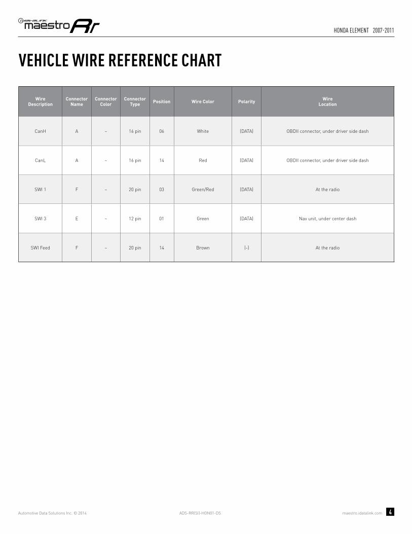
VEHICLE WIRE REFERENCE CHART
WireDescription
Connector Name
ConnectorColor
ConnectorType Position Wire Color Polarity Wire
Location
CanH A ~ 16 pin 06 White (DATA) OBDII connector, under driver side dash
CanL A ~ 16 pin 14 Red (DATA) OBDII connector, under driver side dash
SWI 1 F ~ 20 pin 03 Green/Red (DATA) At the radio
SWI 3 E ~ 12 pin 01 Green (DATA) Nav unit, under center dash
SWI Feed F ~ 20 pin 14 Brown (-) At the radio

ADS-RR(SI)-HON01-DS maestro.idatalink.com
honda element 2007-2011
Automotive Data Solutions Inc. © 2014 5
RADIO WIRE REFERENCE CHART
WireDescription Polarity Wire Color on Maestro
T-Harness Wire Color on Alpine cable Wire Color on Kenwood cable Wire Color on Pioneer cable
Parking Light (+) Orange N/A Orange/White Orange/White
Reverse Light (+) Purple/White Orange/White Purple/White Purple/White
E-Brake (-) Lt Green Yellow/Blue Lt Green Lt Green
Foot Brake (+) Yellow/Black Yellow/Black N/A N/A
VSS (vehicle speed sensor) (DATA) Pink Green/White N/A Pink
Wired Remote (DATA) Blue/Yellow or 3.5 mm 3.5 mm Blue/Yellow 3.5 mm
Mute (-) Brown Pink/Black Brown Yellow/Black

OPTIONAL ACCESSORIESNone
PROGRAMMED FIRMWAREADS-RR(SI)-HON01-DS
PRODUCTS REQUIREDiDatalink Maestro RR Radio Replacement InterfaceiDatalink Compatible Radio
INSTALL GUIDEhONDA FIT 2009-2014
retains steering wheel controls and adds gauges
NOTICE: Automotive Data Solutions Inc. (ADS) recommends having this installation performed by a certified technician. Logos and trademarks used here in are the properties of their respective owners.

ADS-RR(SI)-HON01-DS maestro.idatalink.com
honda Fit 2009-2014
Automotive Data Solutions Inc. © 2014 2
WELCOME
NEED hELP?
Congratulations on the purchase of your iDatalink Maestro RR Radio replacement solution. You are now a few simple steps away from enjoying your new car radio with enhanced features. Before starting your installation, please ensure that your iDatalink Maestro module is programmed with the correct fi rmware for your vehicle and that you carefully review the install guide.
Please note that Maestro RR will only retain functionalities that were originally available in the vehicle.
1 866 427-2999
maestro.idatalink.com/supportwww.12voltdata.com/forum
TABLE OF CONTENTS
Wiring Diagram 3
Vehicle Wire Reference Chart 4
Radio Wire Reference Chart 5

ADS-RR(SI)-HON01-DS maestro.idatalink.com
honda Fit 2009-2014
Automotive Data Solutions Inc. © 2014 3
A
HG
G
H
6
A
4 5 6
7 11
21 3
8 9 10 12
8 7 6 51
10 9
17 16 15 14
4 3 2
13
11
1920 18
12
24 2223 21
10 11 12 13 14 15 16
12
34
56
78
9
06 CANH
14 CANL
MAESTRO RR MODULENOT CONNECTED
NOT CONNECTED
STEP 3
SWI 3SWI 3
E- LOCATED AT NAVIGATION UNITUNDER CENTER DASH
ORANGE/RED - SWI CIRCUIT 3 INPUT
B- LOCATED BEHIND RADIO
OBDII CONNECTORLOCATED UNDER DRIVER SIDE DASH
STEP 5
CONNECT TOAFTERMARKET RADIO
BROWN/RED - CANH
PURPLE/RED - PURPLE/RED - SWI CIRCUIT 1 INPUT
BLACK/WHITE - BLACK/WHITE - SWI GROUND FEED (-) OUTPUT
SWI 1SWI 1
SWI FEEDSWI FEED
BROWN/YELLOW - CANL
WIRES FROMVEHICLE
WIRING DIAGRAMSTEP 1
STEP 2
STEP 3
STEP 5
STEP 4
CONNECT IF THE VEHICLE IS EQUIPPED WITH NAVIGATION.
YELLOW - 12V (+) INPUT
BLACK - GROUND
GRAY/RED - ACCESSORY (+) INPUT
BLACKBLACK
REDRED
YELLOWYELLOW
ADS-RR(SI)-HON01-DS maestro.idatalink.com
honda Fit 2009-2014
Automotive Data Solutions Inc. © 2014 4
VEHICLE WIRE REFERENCE CHART
WireDescription
Connector Name
ConnectorColor
ConnectorType Position Wire Color Polarity Wire
Location
CanH A ~ 16 pin 06 White (DATA) OBDII connector, under driver side dash
CanL A ~ 16 pin 14 Red (DATA) OBDII connector, under driver side dash
SWI 1 B ~ 24 pin 16 Pink (DATA) Behind radio
SWI 3 E ~ 12 pin 01 Green (DATA) Nav unit, under center dash
SWI Feed B ~ 24 pin 05 White (-) Behind radio

ADS-RR(SI)-HON01-DS maestro.idatalink.com
honda Fit 2009-2014
Automotive Data Solutions Inc. © 2014 5
RADIO WIRE REFERENCE CHART
WireDescription Polarity Wire Color on Maestro
T-Harness Wire Color on Alpine cable Wire Color on Kenwood cable Wire Color on Pioneer cable
Parking Light (+) Orange N/A Orange/White Orange/White
Reverse Light (+) Purple/White Orange/White Purple/White Purple/White
E-Brake (-) Lt Green Yellow/Blue Lt Green Lt Green
Foot Brake (+) Yellow/Black Yellow/Black N/A N/A
VSS (vehicle speed sensor) (DATA) Pink Green/White N/A Pink
Wired Remote (DATA) Blue/Yellow or 3.5 mm 3.5 mm Blue/Yellow 3.5 mm
Mute (-) Brown Pink/Black Brown Yellow/Black

OPTIONAL ACCESSORIESNone
PROGRAMMED FIRMWAREADS-RR(SI)-HON01-DS
PRODUCTS REQUIREDiDatalink Maestro RR Radio Replacement InterfaceiDatalink Compatible Radio
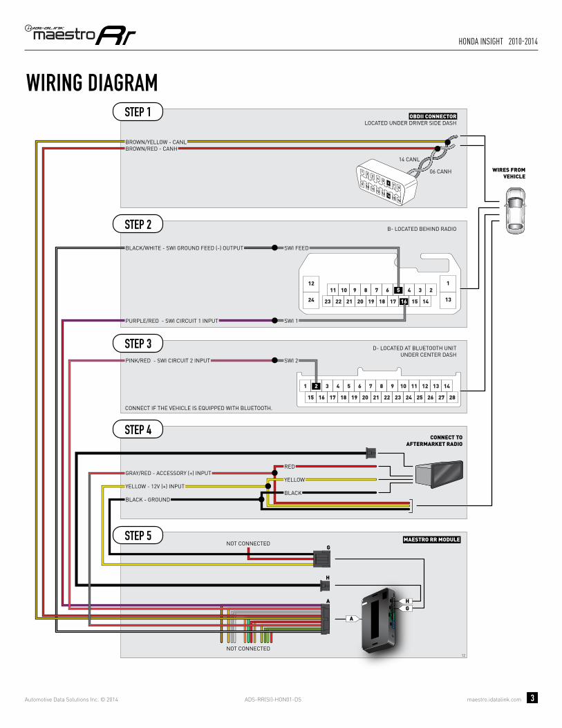
INSTALL GUIDEhONDA INSIGhT
2010-2014retains steering wheel controls and adds gauges
NOTICE: Automotive Data Solutions Inc. (ADS) recommends having this installation performed by a certified technician. Logos and trademarks used here in are the properties of their respective owners.

ADS-RR(SI)-HON01-DS maestro.idatalink.com
honda insight 2010-2014
Automotive Data Solutions Inc. © 2014 2
WELCOME
NEED hELP?
Congratulations on the purchase of your iDatalink Maestro RR Radio replacement solution. You are now a few simple steps away from enjoying your new car radio with enhanced features. Before starting your installation, please ensure that your iDatalink Maestro module is programmed with the correct fi rmware for your vehicle and that you carefully review the install guide.
Please note that Maestro RR will only retain functionalities that were originally available in the vehicle.
1 866 427-2999
maestro.idatalink.com/supportwww.12voltdata.com/forum
TABLE OF CONTENTS
Wiring Diagram 3
Vehicle Wire Reference Chart 4
Radio Wire Reference Chart 5
ADS-RR(SI)-HON01-DS maestro.idatalink.com
honda insight 2010-2014
Automotive Data Solutions Inc. © 2014 3
A
HG
G
H
12
A
8 7 6 51
10 9
17 16 15 14
4 3 2
13
11
1920 18
12
24 2223 21
3 4 5 61 2
17 18 19 20
7 8
21 22 15 16
11 12 13 149 10
23 24 25 26 27 28
10 11 12 13 14 15 16
12
34
56
78
9
06 CANH
14 CANL
MAESTRO RR MODULENOT CONNECTED
NOT CONNECTED
B- LOCATED BEHIND RADIO
D- LOCATED AT BLUETOOTH UNITUNDER CENTER DASH
OBDII CONNECTORLOCATED UNDER DRIVER SIDE DASH
CONNECT TOAFTERMARKET RADIO
BROWN/RED - CANH
PURPLE/RED - PURPLE/RED - SWI CIRCUIT 1 INPUT
BLACK/WHITE - BLACK/WHITE - SWI GROUND FEED (-) OUTPUT
SWI 1SWI 1
SWI 2SWI 2
SWI FEEDSWI FEED
BROWN/YELLOW - CANL
WIRES FROMVEHICLE
PINK/RED - PINK/RED - SWI CIRCUIT 2 INPUT
WIRING DIAGRAMSTEP 1
STEP 2
STEP 3
STEP 5
STEP 4
CONNECT IF THE VEHICLE IS EQUIPPED WITH BLUETOOTH.
YELLOW - 12V (+) INPUT
BLACK - GROUND
GRAY/RED - ACCESSORY (+) INPUT
BLACKBLACK
REDRED
YELLOWYELLOW

ADS-RR(SI)-HON01-DS maestro.idatalink.com
honda insight 2010-2014
Automotive Data Solutions Inc. © 2014 4
VEHICLE WIRE REFERENCE CHART
WireDescription
Connector Name
ConnectorColor
ConnectorType Position Wire Color Polarity Wire
Location
CanH A ~ 16 pin 06 White (DATA) OBDII connector, under driver side dash
CanL A ~ 16 pin 14 Red (DATA) OBDII connector, under driver side dash
SWI 1 B ~ 24 pin 16 Pink (DATA) Behind radio
SWI 2 D ~ 28 pin 02 Green (DATA) Bluetooth unit, under center dash
SWI Feed B ~ 24 pin 05 White (-) Behind radio

ADS-RR(SI)-HON01-DS maestro.idatalink.com
honda insight 2010-2014
Automotive Data Solutions Inc. © 2014 5
RADIO WIRE REFERENCE CHART
WireDescription Polarity Wire Color on Maestro
T-Harness Wire Color on Alpine cable Wire Color on Kenwood cable Wire Color on Pioneer cable
Parking Light (+) Orange N/A Orange/White Orange/White
Reverse Light (+) Purple/White Orange/White Purple/White Purple/White
E-Brake (-) Lt Green Yellow/Blue Lt Green Lt Green
Foot Brake (+) Yellow/Black Yellow/Black N/A N/A
VSS (vehicle speed sensor) (DATA) Pink Green/White N/A Pink
Wired Remote (DATA) Blue/Yellow or 3.5 mm 3.5 mm Blue/Yellow 3.5 mm
Mute (-) Brown Pink/Black Brown Yellow/Black

OPTIONAL ACCESSORIESNone
PROGRAMMED FIRMWAREADS-RR(SI)-HON01-DS
PRODUCTS REQUIREDiDatalink Maestro RR Radio Replacement InterfaceiDatalink Compatible Radio
INSTALL GUIDEhONDA ODySSEy
2007retains steering wheel controls and adds gauges
NOTICE: Automotive Data Solutions Inc. (ADS) recommends having this installation performed by a certified technician. Logos and trademarks used here in are the properties of their respective owners.
ADS-RR(SI)-HON01-DS maestro.idatalink.com
honda odyssey 2007
Automotive Data Solutions Inc. © 2014 2
WELCOME
NEED hELP?
Congratulations on the purchase of your iDatalink Maestro RR Radio replacement solution. You are now a few simple steps away from enjoying your new car radio with enhanced features. Before starting your installation, please ensure that your iDatalink Maestro module is programmed with the correct fi rmware for your vehicle and that you carefully review the install guide.
Please note that Maestro RR will only retain functionalities that were originally available in the vehicle.
1 866 427-2999
maestro.idatalink.com/supportwww.12voltdata.com/forum
TABLE OF CONTENTS
Wiring Diagram 3
Vehicle Wire Reference Chart 4
Radio Wire Reference Chart 5
ADS-RR(SI)-HON01-DS maestro.idatalink.com
honda odyssey 2007
Automotive Data Solutions Inc. © 2014 3
A
HG
G
H
9
A
87
651
109
432
11 141312
6 58 7
14 1316 15
2 14 310 9
12 1118 1720 19
10 11 12 13 14 15 16
12
34
56
78
9
06 CANH
14 CANL
MAESTRO RR MODULENOT CONNECTED
NOT CONNECTED
G- LOCATED AT NAVIGATION UNITUNDER DRIVER SEAT
ORANGE/RED - SWI CIRCUIT 3 INPUT SWI 3SWI 3
OBDII CONNECTORLOCATED UNDER DRIVER SIDE DASH
BROWN/RED - CANHBROWN/YELLOW - CANL
WIRES FROMVEHICLE
F- LOCATED AT THE RADIO
SWI 1SWI 1
SWI FEEDSWI FEED
PURPLE/RED - PURPLE/RED - SWI CIRCUIT 1 INPUT
BLACK/WHITE - BLACK/WHITE - SWI GROUND FEED (-) OUTPUT
CONNECT TOAFTERMARKET RADIO
WIRING DIAGRAMSTEP 1
STEP 2
STEP 3
STEP 5
STEP 4
CONNECT IF THE VEHICLE IS EQUIPPED WITH BLUETOOTH.
YELLOW - 12V (+) INPUT
BLACK - GROUND
GRAY/RED - ACCESSORY (+) INPUT
BLACKBLACK
REDRED
YELLOWYELLOW

ADS-RR(SI)-HON01-DS maestro.idatalink.com
honda odyssey 2007
Automotive Data Solutions Inc. © 2014 4
VEHICLE WIRE REFERENCE CHART
WireDescription
Connector Name
ConnectorColor
ConnectorType Position Wire Color Polarity Wire
Location
CanH A ~ 16 pin 06 White (DATA) OBDII connector, under driver side dash
CanL A ~ 16 pin 14 Red (DATA) OBDII connector, under driver side dash
SWI 1 F ~ 20 pin 03 White (DATA) At the radio
SWI 3 G ~ 14 pin 10 Gray (DATA) At Nav unit, under driver seat
SWI Feed F ~ 20 pin 11 Brown (-) At the radio

ADS-RR(SI)-HON01-DS maestro.idatalink.com
honda odyssey 2007
Automotive Data Solutions Inc. © 2014 5
RADIO WIRE REFERENCE CHART
WireDescription Polarity Wire Color on Maestro
T-Harness Wire Color on Alpine cable Wire Color on Kenwood cable Wire Color on Pioneer cable
Parking Light (+) Orange N/A Orange/White Orange/White
Reverse Light (+) Purple/White Orange/White Purple/White Purple/White
E-Brake (-) Lt Green Yellow/Blue Lt Green Lt Green
Foot Brake (+) Yellow/Black Yellow/Black N/A N/A
VSS (vehicle speed sensor) (DATA) Pink Green/White N/A Pink
Wired Remote (DATA) Blue/Yellow or 3.5 mm 3.5 mm Blue/Yellow 3.5 mm
Mute (-) Brown Pink/Black Brown Yellow/Black

OPTIONAL ACCESSORIESNone
PROGRAMMED FIRMWAREADS-RR(SI)-HON01-DS
PRODUCTS REQUIREDiDatalink Maestro RR Radio Replacement InterfaceiDatalink Compatible Radio
INSTALL GUIDEhONDA ODySSEy
2008-2010retains steering wheel controls and adds gauges
NOTICE: Automotive Data Solutions Inc. (ADS) recommends having this installation performed by a certified technician. Logos and trademarks used here in are the properties of their respective owners.

ADS-RR(SI)-HON01-DS maestro.idatalink.com
honda odyssey 2008-2010
Automotive Data Solutions Inc. © 2014 2
WELCOME
NEED hELP?
Congratulations on the purchase of your iDatalink Maestro RR Radio replacement solution. You are now a few simple steps away from enjoying your new car radio with enhanced features. Before starting your installation, please ensure that your iDatalink Maestro module is programmed with the correct fi rmware for your vehicle and that you carefully review the install guide.
Please note that Maestro RR will only retain functionalities that were originally available in the vehicle.
1 866 427-2999
maestro.idatalink.com/supportwww.12voltdata.com/forum
TABLE OF CONTENTS
Wiring Diagram 3
Vehicle Wire Reference Chart 4
Radio Wire Reference Chart 5

ADS-RR(SI)-HON01-DS maestro.idatalink.com
honda odyssey 2008-2010
Automotive Data Solutions Inc. © 2014 3
A
HG
G
H
8
A
65 87
1413 1615
21 43
109 11 12
3 4 5 61 2
17 18 19 20
7 8
21 22 15 16
11 12 13 149 10
23 24 25 26 27 28
10 11 12 13 14 15 16
12
34
56
78
9
06 CANH
14 CANL
8 7 6 5 110 9
17 16 15 14
4 3 2
13 12 111920 18
MAESTRO RR MODULENOT CONNECTED
NOT CONNECTED
H- LOCATED BEHIND NAVIGATION UNIT
ORANGE/RED - SWI CIRCUIT 3 INPUT SWI 3SWI 3
D- LOCATED AT BLUETOOTH UNITUNDER CENTER DASH
OBDII CONNECTORLOCATED UNDER DRIVER SIDE DASH
BROWN/RED - CANH
SWI 2SWI 2
BROWN/YELLOW - CANL
WIRES FROMVEHICLE
PINK/RED - PINK/RED - SWI CIRCUIT 2 INPUT
C- LOCATED BEHIND RADIO
PURPLE/RED - PURPLE/RED - SWI CIRCUIT 1 INPUT
BLACK/WHITE - BLACK/WHITE - SWI GROUND FEED (-) OUTPUT
SWI 1SWI 1
SWI FEEDSWI FEED
CONNECT TOAFTERMARKET RADIO
WIRING DIAGRAMSTEP 1
STEP 2
STEP 3
STEP 4
STEP 5
STEP 6
CONNECT IF THE VEHICLE IS EQUIPPED WITH BLUETOOTH.
CONNECT IF THE VEHICLE IS EQUIPPED WITH NAVIGATION.
YELLOW - 12V (+) INPUT
BLACK - GROUND
GRAY/RED - ACCESSORY (+) INPUT
BLACKBLACK
REDRED
YELLOWYELLOW

ADS-RR(SI)-HON01-DS maestro.idatalink.com
honda odyssey 2008-2010
Automotive Data Solutions Inc. © 2014 4
VEHICLE WIRE REFERENCE CHART
WireDescription
Connector Name
ConnectorColor
ConnectorType Position Wire Color Polarity Wire
Location
CanH A ~ 16 pin 06 White (DATA) OBDII connector, under driver side dash
CanL A ~ 16 pin 14 Red (DATA) OBDII connector, under driver side dash
SWI 1 C ~ 20 pin 07 White (DATA) Behind radio
SWI 2 D ~ 28 pin 02 Blue (DATA) Bluetooth unit, under center dash
SWI 3 H ~ 16 pin 12 Gray (DATA) Behind Nav unit
SWI Feed C ~ 20 pin 06 Brown (-) Behind radio

ADS-RR(SI)-HON01-DS maestro.idatalink.com
honda odyssey 2008-2010
Automotive Data Solutions Inc. © 2014 5
RADIO WIRE REFERENCE CHART
WireDescription Polarity Wire Color on Maestro
T-Harness Wire Color on Alpine cable Wire Color on Kenwood cable Wire Color on Pioneer cable
Parking Light (+) Orange N/A Orange/White Orange/White
Reverse Light (+) Purple/White Orange/White Purple/White Purple/White
E-Brake (-) Lt Green Yellow/Blue Lt Green Lt Green
Foot Brake (+) Yellow/Black Yellow/Black N/A N/A
VSS (vehicle speed sensor) (DATA) Pink Green/White N/A Pink
Wired Remote (DATA) Blue/Yellow or 3.5 mm 3.5 mm Blue/Yellow 3.5 mm
Mute (-) Brown Pink/Black Brown Yellow/Black

OPTIONAL ACCESSORIESNone
PROGRAMMED FIRMWAREADS-RR(SI)-HON01-DS
PRODUCTS REQUIREDiDatalink Maestro RR Radio Replacement InterfaceiDatalink Compatible Radio
INSTALL GUIDEhONDA ODySSEy
2011-2014retains steering wheel controls and adds gauges
NOTICE: Automotive Data Solutions Inc. (ADS) recommends having this installation performed by a certified technician. Logos and trademarks used here in are the properties of their respective owners.

ADS-RR(SI)-HON01-DS maestro.idatalink.com
honda odyssey 2011-2014
Automotive Data Solutions Inc. © 2014 2
WELCOME
NEED hELP?
Congratulations on the purchase of your iDatalink Maestro RR Radio replacement solution. You are now a few simple steps away from enjoying your new car radio with enhanced features. Before starting your installation, please ensure that your iDatalink Maestro module is programmed with the correct fi rmware for your vehicle and that you carefully review the install guide.
Please note that Maestro RR will only retain functionalities that were originally available in the vehicle.
1 866 427-2999
maestro.idatalink.com/supportwww.12voltdata.com/forum
TABLE OF CONTENTS
Wiring Diagram 3
Vehicle Wire Reference Chart 4
Radio Wire Reference Chart 5

ADS-RR(SI)-HON01-DS maestro.idatalink.com
honda odyssey 2011-2014
Automotive Data Solutions Inc. © 2014 3
A
HG
G
H
7
A
8 7 6 51
10 9
17 16 15 14
4 3 2
13
11
1920 18
12
24 2223 21
6 58 714 1316 15 2 14 310 911
18 1720 19212223
12
25 2427 262829303132
10 11 12 13 14 15 16
12
34
56
78
9
06 CANH
14 CANL
MAESTRO RR MODULENOT CONNECTED
NOT CONNECTED
OBDII CONNECTORLOCATED UNDER DRIVER SIDE DASH
CONNECT TOAFTERMARKET RADIO
BROWN/RED - CANH
PURPLE/RED - PURPLE/RED - SWI CIRCUIT 1 INPUT
BLACK/WHITE - BLACK/WHITE - SWI GROUND FEED (-) OUTPUT
B- LOCATED BEHIND RADIO
SWI 1SWI 1
SWI FEEDSWI FEED
SWI 1SWI 1
SWI FEEDSWI FEED
BROWN/YELLOW - CANL
WIRES FROMVEHICLE
I- LOCATED AT HANDS FREE UNITTO THE RIGHT OF RADIO
SWI 2SWI 2PINK/RED - PINK/RED - SWI CIRCUIT 2 INPUT
WIRING DIAGRAMSTEP 1
STEP 2
STEP 3
STEP 5
STEP 4
CONNECT IF THE VEHICLE IS EQUIPPED WITH BLUETOOTH.
YELLOW - 12V (+) INPUT
BLACK - GROUND
GRAY/RED - ACCESSORY (+) INPUT
BLACKBLACK
REDRED
YELLOWYELLOW
ADS-RR(SI)-HON01-DS maestro.idatalink.com
honda odyssey 2011-2014
Automotive Data Solutions Inc. © 2014 4
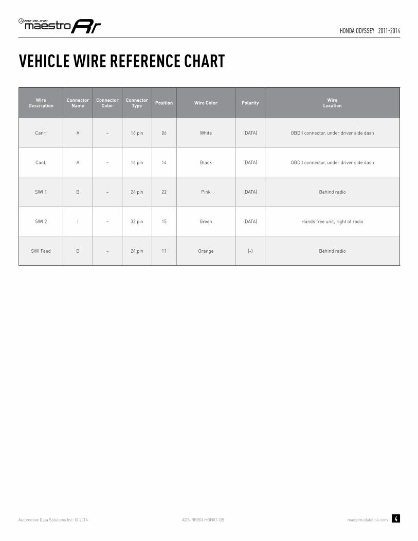
VEHICLE WIRE REFERENCE CHART
WireDescription
Connector Name
ConnectorColor
ConnectorType Position Wire Color Polarity Wire
Location
CanH A ~ 16 pin 06 White (DATA) OBDII connector, under driver side dash
CanL A ~ 16 pin 14 Black (DATA) OBDII connector, under driver side dash
SWI 1 B ~ 24 pin 22 Pink (DATA) Behind radio
SWI 2 I ~ 32 pin 15 Green (DATA) Hands free unit, right of radio
SWI Feed B ~ 24 pin 11 Orange (-) Behind radio

ADS-RR(SI)-HON01-DS maestro.idatalink.com
honda odyssey 2011-2014
Automotive Data Solutions Inc. © 2014 5
RADIO WIRE REFERENCE CHART
WireDescription Polarity Wire Color on Maestro
T-Harness Wire Color on Alpine cable Wire Color on Kenwood cable Wire Color on Pioneer cable
Parking Light (+) Orange N/A Orange/White Orange/White
Reverse Light (+) Purple/White Orange/White Purple/White Purple/White
E-Brake (-) Lt Green Yellow/Blue Lt Green Lt Green
Foot Brake (+) Yellow/Black Yellow/Black N/A N/A
VSS (vehicle speed sensor) (DATA) Pink Green/White N/A Pink
Wired Remote (DATA) Blue/Yellow or 3.5 mm 3.5 mm Blue/Yellow 3.5 mm
Mute (-) Brown Pink/Black Brown Yellow/Black

OPTIONAL ACCESSORIESNone
PROGRAMMED FIRMWAREADS-RR(SI)-HON01-DS
PRODUCTS REQUIREDiDatalink Maestro RR Radio Replacement InterfaceiDatalink Compatible Radio
INSTALL GUIDEhONDA PILOT 2009-2014
retains steering wheel controls and adds gauges
NOTICE: Automotive Data Solutions Inc. (ADS) recommends having this installation performed by a certified technician. Logos and trademarks used here in are the properties of their respective owners.

ADS-RR(SI)-HON01-DS maestro.idatalink.com
honda Pilot 2009-2014
Automotive Data Solutions Inc. © 2014 2
WELCOME
NEED hELP?
Congratulations on the purchase of your iDatalink Maestro RR Radio replacement solution. You are now a few simple steps away from enjoying your new car radio with enhanced features. Before starting your installation, please ensure that your iDatalink Maestro module is programmed with the correct fi rmware for your vehicle and that you carefully review the install guide.
Please note that Maestro RR will only retain functionalities that were originally available in the vehicle.
1 866 427-2999
maestro.idatalink.com/supportwww.12voltdata.com/forum
TABLE OF CONTENTS
Wiring Diagram 3
Vehicle Wire Reference Chart 4
Radio Wire Reference Chart 5

ADS-RR(SI)-HON01-DS maestro.idatalink.com
honda Pilot 2009-2014
Automotive Data Solutions Inc. © 2014 3
A
HG
G
H
10
A
65 87
1413 1615
21 43
109 11 12
8 7 6 51
10 9
17 16 15 14
4 3 2
13
11
1920 18
12
24 2223 21
3 4 5 61 2
17 18 19 20
7 8
21 22 15 16
11 12 13 149 10
23 24 25 26 27 28
10 11 12 13 14 15 16
12
34
56
78
9
06 CANH
14 CANL
MAESTRO RR MODULENOT CONNECTED
NOT CONNECTED
OBDII CONNECTORLOCATED UNDER DRIVER SIDE DASH
BROWN/RED - CANHBROWN/YELLOW - CANL
SWI 3SWI 3
H- LOCATED BEHIND NAVIGATION UNIT
ORANGE/RED - SWI CIRCUIT 3 INPUT
B- LOCATED BEHIND RADIO
D- LOCATED AT BLUETOOTH UNITUNDER CENTER DASH
CONNECT TOAFTERMARKET RADIO
PURPLE/RED - PURPLE/RED - SWI CIRCUIT 1 INPUT
BLACK/WHITE - BLACK/WHITE - SWI GROUND FEED (-) OUTPUT
SWI 1SWI 1
SWI 2SWI 2
SWI FEEDSWI FEED
WIRES FROMVEHICLE
PINK/RED - PINK/RED - SWI CIRCUIT 2 INPUT
WIRING DIAGRAMSTEP 1
STEP 2
STEP 3
STEP 4
STEP 5
STEP 6
CONNECT IF THE VEHICLE IS EQUIPPED WITH BLUETOOTH.
CONNECT IF THE VEHICLE IS EQUIPPED WITH NAVIGATION.
YELLOW - 12V (+) INPUT
BLACK - GROUND
GRAY/RED - ACCESSORY (+) INPUT
BLACKBLACK
REDRED
YELLOWYELLOW
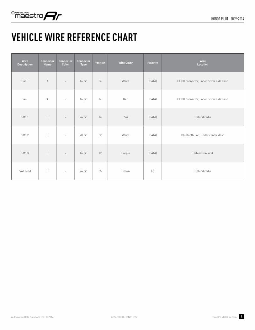
ADS-RR(SI)-HON01-DS maestro.idatalink.com
honda Pilot 2009-2014
Automotive Data Solutions Inc. © 2014 4
VEHICLE WIRE REFERENCE CHART
WireDescription
Connector Name
ConnectorColor
ConnectorType Position Wire Color Polarity Wire
Location
CanH A ~ 16 pin 06 White (DATA) OBDII connector, under driver side dash
CanL A ~ 16 pin 14 Red (DATA) OBDII connector, under driver side dash
SWI 1 B ~ 24 pin 16 Pink (DATA) Behind radio
SWI 2 D ~ 28 pin 02 White (DATA) Bluetooth unit, under center dash
SWI 3 H ~ 16 pin 12 Purple (DATA) Behind Nav unit
SWI Feed B ~ 24 pin 05 Brown (-) Behind radio

ADS-RR(SI)-HON01-DS maestro.idatalink.com
honda Pilot 2009-2014
Automotive Data Solutions Inc. © 2014 5
RADIO WIRE REFERENCE CHART
WireDescription Polarity Wire Color on Maestro
T-Harness Wire Color on Alpine cable Wire Color on Kenwood cable Wire Color on Pioneer cable
Parking Light (+) Orange N/A Orange/White Orange/White
Reverse Light (+) Purple/White Orange/White Purple/White Purple/White
E-Brake (-) Lt Green Yellow/Blue Lt Green Lt Green
Foot Brake (+) Yellow/Black Yellow/Black N/A N/A
VSS (vehicle speed sensor) (DATA) Pink Green/White N/A Pink
Wired Remote (DATA) Blue/Yellow or 3.5 mm 3.5 mm Blue/Yellow 3.5 mm
Mute (-) Brown Pink/Black Brown Yellow/Black

OPTIONAL ACCESSORIESNone
PROGRAMMED FIRMWAREADS-RR(SI)-HON01-DS
PRODUCTS REQUIREDiDatalink Maestro RR Radio Replacement InterfaceiDatalink Compatible Radio
INSTALL GUIDEhONDA RIDGELINE
2009-2014retains steering wheel controls and adds gauges
NOTICE: Automotive Data Solutions Inc. (ADS) recommends having this installation performed by a certified technician. Logos and trademarks used here in are the properties of their respective owners.

ADS-RR(SI)-HON01-DS maestro.idatalink.com
honda ridgeline 2009-2014
Automotive Data Solutions Inc. © 2014 2
WELCOME
NEED hELP?
Congratulations on the purchase of your iDatalink Maestro RR Radio replacement solution. You are now a few simple steps away from enjoying your new car radio with enhanced features. Before starting your installation, please ensure that your iDatalink Maestro module is programmed with the correct fi rmware for your vehicle and that you carefully review the install guide.
Please note that Maestro RR will only retain functionalities that were originally available in the vehicle.
1 866 427-2999
maestro.idatalink.com/supportwww.12voltdata.com/forum
TABLE OF CONTENTS
Wiring Diagram 3
Vehicle Wire Reference Chart 4
Radio Wire Reference Chart 5

ADS-RR(SI)-HON01-DS maestro.idatalink.com
honda ridgeline 2009-2014
Automotive Data Solutions Inc. © 2014 3
A
HG
G
H
10
A
65 87
1413 1615
21 43
109 11 12
8 7 6 51
10 9
17 16 15 14
4 3 2
13
11
1920 18
12
24 2223 21
3 4 5 61 2
17 18 19 20
7 8
21 22 15 16
11 12 13 149 10
23 24 25 26 27 28
10 11 12 13 14 15 16
12
34
56
78
9
06 CANH
14 CANL
MAESTRO RR MODULENOT CONNECTED
NOT CONNECTED
OBDII CONNECTORLOCATED UNDER DRIVER SIDE DASH
BROWN/RED - CANHBROWN/YELLOW - CANL
SWI 3SWI 3
H- LOCATED BEHIND NAVIGATION UNIT
ORANGE/RED - SWI CIRCUIT 3 INPUT
B- LOCATED BEHIND RADIO
D- LOCATED AT BLUETOOTH UNITUNDER CENTER DASH
CONNECT TOAFTERMARKET RADIO
PURPLE/RED - PURPLE/RED - SWI CIRCUIT 1 INPUT
BLACK/WHITE - BLACK/WHITE - SWI GROUND FEED (-) OUTPUT
SWI 1SWI 1
SWI 2SWI 2
SWI FEEDSWI FEED
WIRES FROMVEHICLE
PINK/RED - PINK/RED - SWI CIRCUIT 2 INPUT
WIRING DIAGRAMSTEP 1
STEP 2
STEP 3
STEP 4
STEP 5
STEP 6
CONNECT IF THE VEHICLE IS EQUIPPED WITH BLUETOOTH.
CONNECT IF THE VEHICLE IS EQUIPPED WITH NAVIGATION.
YELLOW - 12V (+) INPUT
BLACK - GROUND
GRAY/RED - ACCESSORY (+) INPUT
BLACKBLACK
REDRED
YELLOWYELLOW

ADS-RR(SI)-HON01-DS maestro.idatalink.com
honda ridgeline 2009-2014
Automotive Data Solutions Inc. © 2014 4
VEHICLE WIRE REFERENCE CHART
WireDescription
Connector Name
ConnectorColor
ConnectorType Position Wire Color Polarity Wire
Location
CanH A ~ 16 pin 06 White (DATA) OBDII connector, under driver side dash
CanL A ~ 16 pin 14 Red (DATA) OBDII connector, under driver side dash
SWI 1 B ~ 24 pin 16 Green/Red (DATA) Behind radio
SWI 2 D ~ 28 pin 02 Purple (DATA) Bluetooth unit, under center dash
SWI 3 H ~ 16 pin 12 Gray (DATA) Behind Nav unit
SWI Feed B ~ 24 pin 05 Brown (-) Behind radio
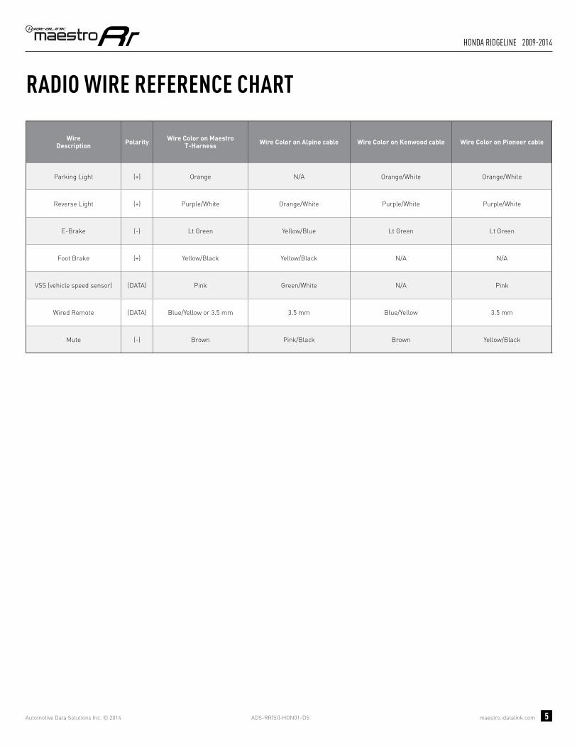
ADS-RR(SI)-HON01-DS maestro.idatalink.com
honda ridgeline 2009-2014
Automotive Data Solutions Inc. © 2014 5
RADIO WIRE REFERENCE CHART
WireDescription Polarity Wire Color on Maestro
T-Harness Wire Color on Alpine cable Wire Color on Kenwood cable Wire Color on Pioneer cable
Parking Light (+) Orange N/A Orange/White Orange/White
Reverse Light (+) Purple/White Orange/White Purple/White Purple/White
E-Brake (-) Lt Green Yellow/Blue Lt Green Lt Green
Foot Brake (+) Yellow/Black Yellow/Black N/A N/A
VSS (vehicle speed sensor) (DATA) Pink Green/White N/A Pink
Wired Remote (DATA) Blue/Yellow or 3.5 mm 3.5 mm Blue/Yellow 3.5 mm
Mute (-) Brown Pink/Black Brown Yellow/Black