how to select and set circuit breakers for generators the protection of... · page 3 of 7...
TRANSCRIPT
Page 1 of 7
©Terasaki Electric (Europe) Ltd 2017
How to Select and Set Circuit Breakers for
Generators
Introduction Generators differ from other electrical power sources in their ability to withstand
electrical overloads and fault currents. These differences should be respected when
selecting and setting circuit breakers which protect generators.
This guide explains the parameters of generators and circuit breakers which should be
considered when selecting and setting equipment. It contains a five-step selection and
setting guide with accompanying graphs and tables.
Author: Tim Campbell BEng (Hons) MIET, Marketing Manager, Terasaki Electric (Europe) Ltd.

Page 2 of 7
©Terasaki Electric (Europe) Ltd 2017
Contents
page
Expertise in Generator Protection 4
What is Special about Generator Protection? 5
Table 1. Comparison of Short-circuit Fault Current Withstand for Various Equipment 5
Five Step Selection and Setting Guide 6
Figure 1. Parameters for Selection and Setting: Graphical 7
Table 2. Generator Protection Circuit Breaker Models for Various Values of Iflc and Isc Max. 8
Appendix 1. Thermal-magnetic MCCBs with Low Instantaneous Trip for Generators
Appendix 2. Electronic MCCBs with Selectable Characteristics
Appendix 3. ACBs with AGR-21BS and AGR-31BS dedicated generator protection relays

Page 3 of 7
©Terasaki Electric (Europe) Ltd 2017
Expertise in Generator Protection Terasaki supply circuit breakers which protect people and equipment from electrical faults. We
provide protection for generators in all industry sectors. For example:
Marine We supply more switchgear for ships than any other manufacturer. Our Circuit Breakers and
GAC 21 Generating Plant Management System are used to protect and control generators on
thousands of ocean-going vessels.
Air Circuit Breaker Moulded Case Circuit Breakers Generator Management System
Standby Power Terasaki circuit breakers are used by:
Himoinsa / FG Wilson / Yanmar / Gesan / Aggreko / Ascot / Atlas Copco
Automatic Changeover for Critical Supplies Our automatic changeover systems can automatically start the standby generator and activate the
switching sequence if the mains power supply in hospitals, data centres or airports fails. Circuit
breakers are interlocked to prevent parallel voltage supply. We can offer changeover solutions for:
Systems with one transformer incoming breaker and one generator incoming breaker
Systems with two transformer incoming breakers
Automatic Changeover System

Page 4 of 7
©Terasaki Electric (Europe) Ltd 2017
What is Special about Generator Protection?
Transformers and generators differ in their ability to withstand electrical overloads and fault
currents. These differences should be respected when you select and set circuit breakers which
protect generators.
Withstand of Short-time Overload Current Transformers can withstand overloads of short duration and may be intentionally overloaded for
pre-defined periods. Generators should never be intentionally overloaded and will be permanently
damaged by sustained overload. The calibration method and threshold settings of overload
protection elements must ensure that the circuit breaker protecting the generator trips before the
windings are damaged.
Withstand of Short-circuit Fault Current
The rotational speed and high reactance of generators mean that they are damaged rapidly when
short-circuited. Short-circuit protection must be selected and configured to operate at lower
thresholds than for cables or transformers. Compare these examples of the abilities of typical
cable, transformers and generators to withstand short-circuit fault current without damage:
Fault current as a multiple of
rated current (%)
Withstand duration before
damage
Cable 250% 1000 seconds
Oil-filled Transformer 300% 300 seconds
Generator 300% 5 seconds
Table 1. Comparison of Short-circuit Fault Current Withstand for Various Equipment. Data courtesy
of http://www.skm.com/applicationguides16.html. Figures are illustrative and should not be used
for design purposes. Always check the manufacturer’s data
Magnitude of Short-Circuit Current Output Circuit breaker protection characteristics have “instantaneous” functions which are dedicated to
short-circuit fault protection. These functions can be set to clear high values of short-circuit
current without intentional time delay (in less than 30 milliseconds for Terasaki air circuit breakers
and less than 20 milliseconds for Terasaki moulded case circuit breakers). The supply source must
be capable of delivering a short-circuit current higher than the user-adjustable instantaneous
operating threshold.
The maximum short-circuit current of a generator or transformer is determined by the impedance
of its winding and its magnetic circuit. Generators under short-circuit have impedance values
which vary according to a transient characteristic but which are always higher than those of
transformers of equivalent power ratings. This means that the maximum deliverable short-circuit
current of a generator is low (typically between 300% and 500% of rated full-load current)*
compared with an equivalent transformer. Circuit breakers must be selected and set to ensure that
the instantaneous protection element will indeed be activated by a short-circuit.
* Reference: http://electrical-engineering-portal.com/calculating-the-short-circuit-current-
synchronous-generator
Page 5 of 7
©Terasaki Electric (Europe) Ltd 2017
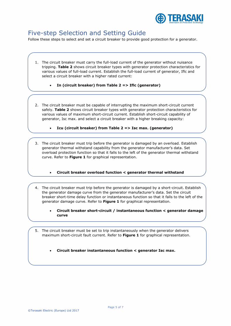
Five-step Selection and Setting Guide Follow these steps to select and set a circuit breaker to provide good protection for a generator.
1. The circuit breaker must carry the full-load current of the generator without nuisance
tripping. Table 2 shows circuit breaker types with generator protection characteristics for
various values of full-load current. Establish the full-load current of generator, Iflc and
select a circuit breaker with a higher rated current:
In (circuit breaker) from Table 2 => Iflc (generator)
2. The circuit breaker must be capable of interrupting the maximum short-circuit current
safely. Table 2 shows circuit breaker types with generator protection characteristics for
various values of maximum short-circuit current. Establish short-circuit capability of
generator, Isc max. and select a circuit breaker with a higher breaking capacity:
Icu (circuit breaker) from Table 2 => Isc max. (generator)
3. The circuit breaker must trip before the generator is damaged by an overload. Establish
generator thermal withstand capability from the generator manufacturer’s data. Set
overload protection function so that it falls to the left of the generator thermal withstand
curve. Refer to Figure 1 for graphical representation.
Circuit breaker overload function < generator thermal withstand
4. The circuit breaker must trip before the generator is damaged by a short-circuit. Establish
the generator damage curve from the generator manufacturer’s data. Set the circuit
breaker short-time delay function or instantaneous function so that it falls to the left of the
generator damage curve. Refer to Figure 1 for graphical representation.
Circuit breaker short-circuit / instantaneous function < generator damage
curve
5. The circuit breaker must be set to trip instantaneously when the generator delivers
maximum short-circuit fault current. Refer to Figure 1 for graphical representation.
Circuit breaker instantaneous function < generator Isc max.
Page 6 of 7
©Terasaki Electric (Europe) Ltd 2017
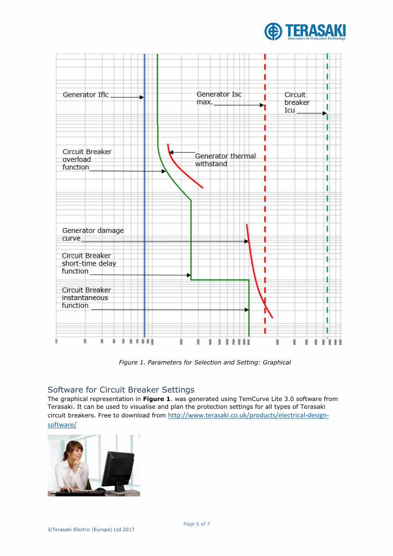
Figure 1. Parameters for Selection and Setting: Graphical
Software for Circuit Breaker Settings The graphical representation in Figure 1. was generated using TemCurve Lite 3.0 software from
Terasaki. It can be used to visualise and plan the protection settings for all types of Terasaki
circuit breakers. Free to download from http://www.terasaki.co.uk/products/electrical-design-
software/

Page 7 of 7
©Terasaki Electric (Europe) Ltd 2017
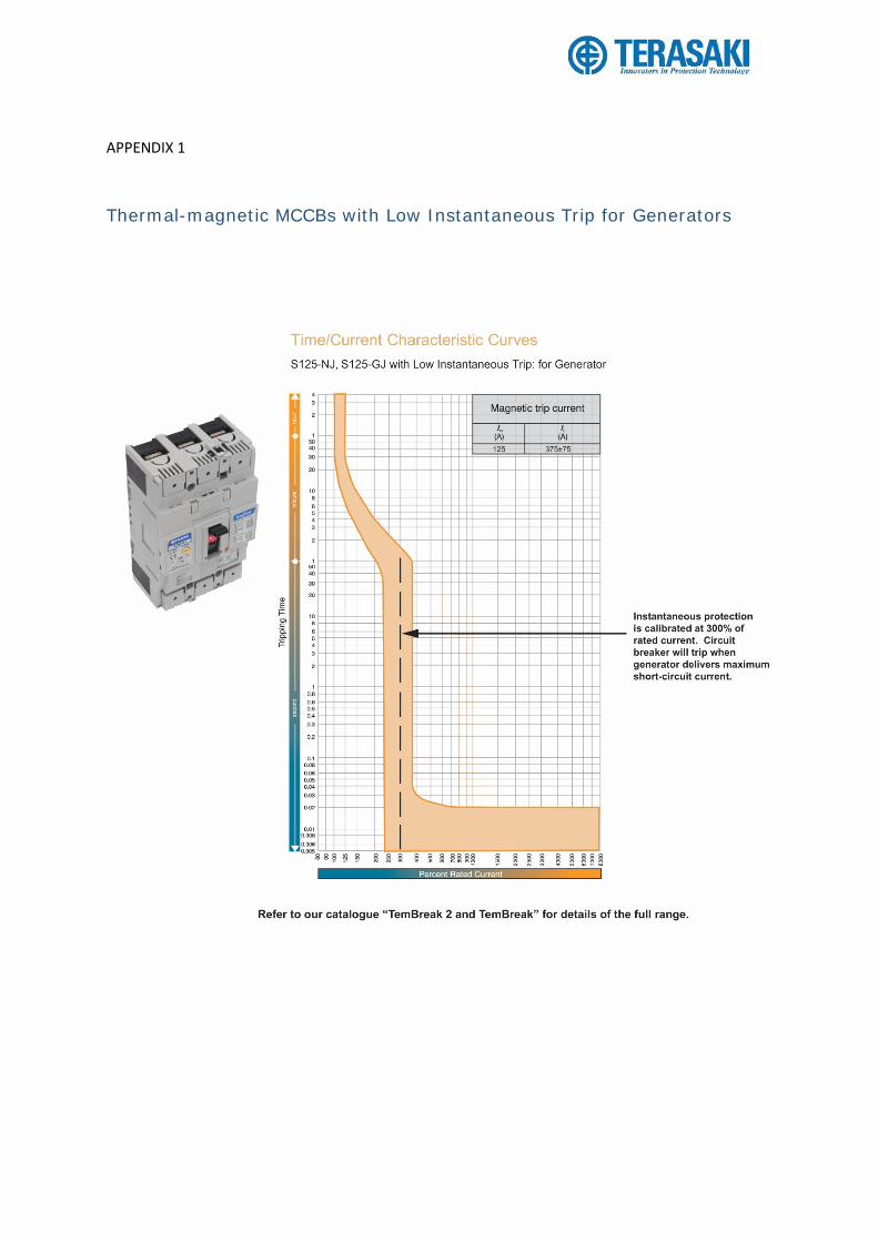
APPENDIX 1
Thermal-magnetic MCCBs with Low Instantaneous Trip for Generators

APPENDIX 2
Electronic MCCBs with Selectable Characteristics

APPENDIX 3
ACBs with AGR-21BS and AGR-31BS dedicated generator protection relays