how to measure total jitter (tj) (rev. b)
TRANSCRIPT

1SCAA120B–September 2012–Revised August 2017Submit Documentation Feedback
Copyright © 2012–2017, Texas Instruments Incorporated
How to Measure Total Jitter (TJ)
Application ReportSCAA120B–September 2012–Revised August 2017
How to Measure Total Jitter (TJ)
Julian Hagedorn, Falk Alicke, and Ankur Verma .................................................................. SVA/SDS/CTP
ABSTRACTToday, the jitter specification, TJ, is used in more and more systems, at the same time the jitterrequirements get lower and lower. Clock generators or jitter cleaners like the CDCM6208 meet thosetough jitter specifications for most systems (for example, TMS320TCI66xx DSP-based systems; seeHardware Design Guide for KeyStone I Devices (SPRABI2). The other side of the coin is that themeasurement equipment has to be feasible to measure the low-noise clock generators. Therefore, themeasurement equipment has to have a lower noise floor than the device under test. This can be achievedby minimizing the noise sources within the measurement equipment.
This application report describes the recommended measurement techniques for TJ. It includes thedescription of the techniques to minimize the noise sources of the measurement equipment. TheCDCM6208 characterization setup is used as an example throughout the application report.
Contents1 Introduction ................................................................................................................... 2
1.1 Noise Sources in an Oscilloscope ................................................................................ 22 Comparison: Phase Noise Analyzer Versus Oscilloscope ............................................................. 33 TJ Characterization Setup................................................................................................... 44 Measurement Results ....................................................................................................... 55 Slew Rate Amplifier Alternatives ......................................................................................... 106 Tradeoffs .................................................................................................................... 107 Digital Serial Analyzer With DPOJET Software ....................................................................... 108 Conclusion .................................................................................................................. 119 References .................................................................................................................. 11
List of Figures
1 Total Jitter Components .................................................................................................... 22 Oscilloscope Noise Sources ............................................................................................... 33 Slew Rate Impact on Measured Clock.................................................................................... 34 Traditional TJ Measurement Setup........................................................................................ 45 PNA Connection to Measure Random Jitter ............................................................................. 56 Improved TJ Measurement Setup With ONET1191P................................................................... 57 122.88 MHz (Integer): TJ = 18.335 ps .................................................................................... 68 122.88 MHz (Integer) With ONET1191P: TJ = 7.722 ps ............................................................... 69 156.25 MHz (6-Bit Fraction): TJ = 49.356 ps ............................................................................ 710 156.25 MHz (6-Bit Fraction) With ONET1191P: TJ = 40.840 ps ...................................................... 711 156.25 MHz (20-Bit Fraction): TJ = 63.69 ps ............................................................................ 812 156.25 MHz (20-Bit Fraction) With ONET1191P: TJ = 54.88 ps ...................................................... 813 312.5 MHz (Integer): TJ = 17.763 ps ..................................................................................... 914 312.5 MHz (Integer) With ONET1191P: TJ = 8.205 ps................................................................. 9
22Oscilloscope Noise
Jitter Measurement Floor Sample Clock JitterSlew Rate
= +
( )
2
Total
Jitter
Random
Jitter
Deterministic
Jitter
Bounded
Jitter
Periodic
Jitter
Data
Dependent
Unbounded, RMS Bounded, pk-pk
Specified as pk-pk for a specific BER
Effectively Unbounded
Specified as peak-to-peak for a Specific BER
Bounded, peak-to-peak
Introduction www.ti.com
2 SCAA120B–September 2012–Revised August 2017Submit Documentation Feedback
Copyright © 2012–2017, Texas Instruments Incorporated
How to Measure Total Jitter (TJ)
TrademarksAll trademarks are the property of their respective owners.
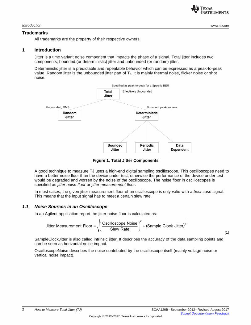
1 IntroductionJitter is a time variant noise component that impacts the phase of a signal. Total jitter includes twocomponents; bounded (or deterministic) jitter and unbounded (or random) jitter.
Deterministic jitter is a predictable and repeatable behavior which can be expressed as a peak-to-peakvalue. Random jitter is the unbounded jitter part of TJ. It is mainly thermal noise, flicker noise or shotnoise.
Figure 1. Total Jitter Components
A good technique to measure TJ uses a high-end digital sampling oscilloscope. This oscilloscopes need tohave a better noise floor than the device under test, otherwise the performance of the device under testwould be degraded and worsen by the noise of the oscilloscope. The noise floor in oscilloscopes isspecified as jitter noise floor or jitter measurement floor.
In most cases, the given jitter measurement floor of an oscilloscope is only valid with a best case signal.This means that the input signal has to meet a certain slew rate.
1.1 Noise Sources in an OscilloscopeIn an Agilent application report the jitter noise floor is calculated as:
(1)
SampleClockJitter is also called intrinsic jitter. It describes the accuracy of the data sampling points andcan be seen as horizontal noise impact.
OscilloscopeNoise describes the noise contributed by the oscilloscope itself (mainly voltage noise orvertical noise impact).

www.ti.com Comparison: Phase Noise Analyzer Versus Oscilloscope
3SCAA120B–September 2012–Revised August 2017Submit Documentation Feedback
Copyright © 2012–2017, Texas Instruments Incorporated
How to Measure Total Jitter (TJ)
Figure 2. Oscilloscope Noise Sources
The simplified input of an oscilloscope is made of an analog-to-digital converter (ADC) which is clocked bythe sampling clock. Additionally, there is the input gain stage which injects the oscilloscope noise.
Figure 3. Slew Rate Impact on Measured Clock
In Figure 3 the slew rate of a clock signal was increased whereas the oscilloscope noise is equal. Theillustration shows that a signal with a slow slew rate is more susceptible to oscilloscope noise than signalswith a high slew rate.
As a consequence, either an oscilloscope which accepts lower slew rate in combination with a very goodjitter measurement floor, or a higher signal slew rates has to be used to measure a device with less impactfrom the oscilloscope. During the device characterization of the CDCM6208 a limiting amplifier(ONET1191P) from TI was used to increase the slew rates of the CDCM6208. The limiting amplifier iscalled ONET1191P or slew-rate amplifier for the remainder of this document.
2 Comparison: Phase Noise Analyzer Versus OscilloscopeTable 1 summarizes TJ and random (or RMS) jitter measurement test results with the oscilloscopecomparing jitter with and without the ONET1191P. As it can be seen using the ONET1191P, the datameasurement on the phase noise analyzer (PNA) and the oscilloscope correlates very well.

TJ Characterization Setup www.ti.com
4 SCAA120B–September 2012–Revised August 2017Submit Documentation Feedback
Copyright © 2012–2017, Texas Instruments Incorporated
How to Measure Total Jitter (TJ)
RJ or RJ with ONET1191P represents the random jitter component of a TJ measurement. TJ or TJ withthe ONET1191P represents the TJ measurements. PNA describes the RMS jitter measurements takenwith a PNA with an integration range of 10 kHz to 20 MHz.
(1) NOTE: The difference between PNA values and RJ with ONET1191P is because the ONET1191P worsens the signal by itsadditive jitter
Table 1. Jitter Measurement
FREQUENCY (DIVIDERFRACTION)
[ps-rms] [ps-rms] [ps-rms] ps-pp ps-pp
PNA (1) RJ RJ WITHONET1191P (1) TJ TJ WITH
ONET1191P122.88 MHz (integer) 0.263 1.252 0.507 18.335 7.722156.25 MHz (6-bit fractional) 0.474 1.715 0.959 49.356 40.84156.25 MHz (20-bit fractional) 0.635 2.06 0.773 63.69 54.88312.50 MHz (integer) 0.255 1.212 0.483 17.763 8.205
3 TJ Characterization SetupDuring TJ characterization of CDCM6208, the setup shown in Figure 6 was used.
Figure 4. Traditional TJ Measurement Setup

www.ti.com Measurement Results
5SCAA120B–September 2012–Revised August 2017Submit Documentation Feedback
Copyright © 2012–2017, Texas Instruments Incorporated
How to Measure Total Jitter (TJ)
Figure 5. PNA Connection to Measure Random Jitter
Figure 6. Improved TJ Measurement Setup With ONET1191P
4 Measurement ResultsFigure 7 through Figure 14 show the measured results for TJ with and without the ONET1191P withdifferent output frequencies.

Measurement Results www.ti.com
6 SCAA120B–September 2012–Revised August 2017Submit Documentation Feedback
Copyright © 2012–2017, Texas Instruments Incorporated
How to Measure Total Jitter (TJ)
Figure 7. 122.88 MHz (Integer): TJ = 18.335 ps
Figure 8. 122.88 MHz (Integer) With ONET1191P: TJ = 7.722 ps

www.ti.com Measurement Results
7SCAA120B–September 2012–Revised August 2017Submit Documentation Feedback
Copyright © 2012–2017, Texas Instruments Incorporated
How to Measure Total Jitter (TJ)
Figure 9. 156.25 MHz (6-Bit Fraction): TJ = 49.356 ps
Figure 10. 156.25 MHz (6-Bit Fraction) With ONET1191P: TJ = 40.840 ps

Measurement Results www.ti.com
8 SCAA120B–September 2012–Revised August 2017Submit Documentation Feedback
Copyright © 2012–2017, Texas Instruments Incorporated
How to Measure Total Jitter (TJ)
Figure 11. 156.25 MHz (20-Bit Fraction): TJ = 63.69 ps
Figure 12. 156.25 MHz (20-Bit Fraction) With ONET1191P: TJ = 54.88 ps

www.ti.com Measurement Results
9SCAA120B–September 2012–Revised August 2017Submit Documentation Feedback
Copyright © 2012–2017, Texas Instruments Incorporated
How to Measure Total Jitter (TJ)
Figure 13. 312.5 MHz (Integer): TJ = 17.763 ps
Figure 14. 312.5 MHz (Integer) With ONET1191P: TJ = 8.205 ps

2 2Total Jitter Jitter DUT Jitter Slew Rate Amplifier= + )2
(Jitter DUT) + (Jitter Slew Rate Amplifier)2 22 2
Slew Rate Amplifier Alternatives www.ti.com
10 SCAA120B–September 2012–Revised August 2017Submit Documentation Feedback
Copyright © 2012–2017, Texas Instruments Incorporated
How to Measure Total Jitter (TJ)
5 Slew Rate Amplifier AlternativesAs an alternative to the ONET1191P, any other differential buffer with a rise and fall time smaller than 100ps can be used.
CDCLVP12xx or LMK00301 could be used as an alternative, but the rise and fall times are still too slow.
Additionally, oscilloscope manufacturer LeCroy has a proprietary solution called SDA-LNES (Low-noiseedge sharper).
6 TradeoffsUsing a slew-rate amplifier to lower the oscilloscope noise impact, the random jitter component of thedevice under test is increased. Each component in the measurement chain worsens the random jitter. Theimpact can be calculated with this formula:
(2)
High slew rates require oscilloscopes with a high sample rate (at least 40 GSPS) and enough memory tocapture a signal over a long time. 40 GSPS means that the oscilloscope measurement point resolution is25 ps. As an example, a 20 GSPS oscilloscope measures every 50 ps. Due to the fact that theONET1191P has a typical rise time of 45 ps, a 40-GSPS oscilloscope is mandatory to measure the signaledge correctly. Otherwise, the under sampling effect adds additional jitter to the measurement.
7 Digital Serial Analyzer With DPOJET SoftwareAs an example for Jitter measurement, Tektronix 16 GHz 50GS/s Digital Serial Analyzer with DPOJETsoftware can be used for eye width/height and jitter analysis. Common DPOJET measurement parametersconfiguration used are shown in Table 2. Listed in this instruction set is the recommended process for theeye diagram measurement, using a Tektronix 16-GHz oscilloscope with DPOJET software. This softwareoverlays all the possible unit intervals of data and conducts the horizontal and vertical measurements. Thevertical measurement is in terms of voltage and the horizontal is in terms of UI.
Table 2. DPOJET Measurement Parameters Configuration
MEASUREMENT
EDGES
CLOCKRECOVERY RjDj FILTERS GENERAL GLOBAL BIT CONFIG.
TJ@BER Data
Method: PLL-Custom PWPLL Mode:Type ILoop BW:FPCLK/40Apply to All:Apply
PatternDetection/Control: ManualPattern Type:ArbitraryWindow Length5UI Target BER:1 E-10Apply to All:Apply
HPF (F1)Filter Spec:2nd OrderFreq (F1):FPCLK/40LPF (F2)Filter Spec:No FilterApply to All:Apply
Default Default —
Width@BER Data Same Above Same Above Same Above Default Default —Height — — — — Default Default Bit Type: All Bit

www.ti.com Conclusion
11SCAA120B–September 2012–Revised August 2017Submit Documentation Feedback
Copyright © 2012–2017, Texas Instruments Incorporated
How to Measure Total Jitter (TJ)
8 ConclusionTotal jitter has to be measured with an oscilloscope that has a reasonable jitter measurement floor smallerthan 300 fs. In today’s oscilloscopes, an external slew rate amplifier must be used to achieve such lowjitter measurement floors.
In addition, the oscilloscope must have at least 40 GSPS to ensure a proper amount of sampling points tomeasure the fast slew rate of the slew rate amplifier and to prevent under sampling. Take the amount ofscope memory into account, t as well, because the scopes must have a minimum number of samples tocalculate TJ.
9 References1. CDCM6208 2:8 Clock Generator, Jitter Cleaner with Fractional Dividers (SCAS931)2. Understanding the Jitter Specification in Oscilloscopes; EETimes3. SDA-LNES; LeCroy

Revision History www.ti.com
12 SCAA120B–September 2012–Revised August 2017Submit Documentation Feedback
Copyright © 2012–2017, Texas Instruments Incorporated
Revision History
Revision HistoryNOTE: Page numbers for previous revisions may differ from page numbers in the current version.
Changes from A Revision (December 2012) to B Revision ........................................................................................... Page
• Added the Digital Serial Analyzer With DPOJET Software section ............................................................... 10

IMPORTANT NOTICE FOR TI DESIGN INFORMATION AND RESOURCES
Texas Instruments Incorporated (‘TI”) technical, application or other design advice, services or information, including, but not limited to,reference designs and materials relating to evaluation modules, (collectively, “TI Resources”) are intended to assist designers who aredeveloping applications that incorporate TI products; by downloading, accessing or using any particular TI Resource in any way, you(individually or, if you are acting on behalf of a company, your company) agree to use it solely for this purpose and subject to the terms ofthis Notice.TI’s provision of TI Resources does not expand or otherwise alter TI’s applicable published warranties or warranty disclaimers for TIproducts, and no additional obligations or liabilities arise from TI providing such TI Resources. TI reserves the right to make corrections,enhancements, improvements and other changes to its TI Resources.You understand and agree that you remain responsible for using your independent analysis, evaluation and judgment in designing yourapplications and that you have full and exclusive responsibility to assure the safety of your applications and compliance of your applications(and of all TI products used in or for your applications) with all applicable regulations, laws and other applicable requirements. Yourepresent that, with respect to your applications, you have all the necessary expertise to create and implement safeguards that (1)anticipate dangerous consequences of failures, (2) monitor failures and their consequences, and (3) lessen the likelihood of failures thatmight cause harm and take appropriate actions. You agree that prior to using or distributing any applications that include TI products, youwill thoroughly test such applications and the functionality of such TI products as used in such applications. TI has not conducted anytesting other than that specifically described in the published documentation for a particular TI Resource.You are authorized to use, copy and modify any individual TI Resource only in connection with the development of applications that includethe TI product(s) identified in such TI Resource. NO OTHER LICENSE, EXPRESS OR IMPLIED, BY ESTOPPEL OR OTHERWISE TOANY OTHER TI INTELLECTUAL PROPERTY RIGHT, AND NO LICENSE TO ANY TECHNOLOGY OR INTELLECTUAL PROPERTYRIGHT OF TI OR ANY THIRD PARTY IS GRANTED HEREIN, including but not limited to any patent right, copyright, mask work right, orother intellectual property right relating to any combination, machine, or process in which TI products or services are used. Informationregarding or referencing third-party products or services does not constitute a license to use such products or services, or a warranty orendorsement thereof. Use of TI Resources may require a license from a third party under the patents or other intellectual property of thethird party, or a license from TI under the patents or other intellectual property of TI.TI RESOURCES ARE PROVIDED “AS IS” AND WITH ALL FAULTS. TI DISCLAIMS ALL OTHER WARRANTIES ORREPRESENTATIONS, EXPRESS OR IMPLIED, REGARDING TI RESOURCES OR USE THEREOF, INCLUDING BUT NOT LIMITED TOACCURACY OR COMPLETENESS, TITLE, ANY EPIDEMIC FAILURE WARRANTY AND ANY IMPLIED WARRANTIES OFMERCHANTABILITY, FITNESS FOR A PARTICULAR PURPOSE, AND NON-INFRINGEMENT OF ANY THIRD PARTY INTELLECTUALPROPERTY RIGHTS.TI SHALL NOT BE LIABLE FOR AND SHALL NOT DEFEND OR INDEMNIFY YOU AGAINST ANY CLAIM, INCLUDING BUT NOTLIMITED TO ANY INFRINGEMENT CLAIM THAT RELATES TO OR IS BASED ON ANY COMBINATION OF PRODUCTS EVEN IFDESCRIBED IN TI RESOURCES OR OTHERWISE. IN NO EVENT SHALL TI BE LIABLE FOR ANY ACTUAL, DIRECT, SPECIAL,COLLATERAL, INDIRECT, PUNITIVE, INCIDENTAL, CONSEQUENTIAL OR EXEMPLARY DAMAGES IN CONNECTION WITH ORARISING OUT OF TI RESOURCES OR USE THEREOF, AND REGARDLESS OF WHETHER TI HAS BEEN ADVISED OF THEPOSSIBILITY OF SUCH DAMAGES.You agree to fully indemnify TI and its representatives against any damages, costs, losses, and/or liabilities arising out of your non-compliance with the terms and provisions of this Notice.This Notice applies to TI Resources. Additional terms apply to the use and purchase of certain types of materials, TI products and services.These include; without limitation, TI’s standard terms for semiconductor products http://www.ti.com/sc/docs/stdterms.htm), evaluationmodules, and samples (http://www.ti.com/sc/docs/sampterms.htm).
Mailing Address: Texas Instruments, Post Office Box 655303, Dallas, Texas 75265Copyright © 2017, Texas Instruments Incorporated