how to make 1)lock-in amplifier 2)current source
TRANSCRIPT

How to make 1)Lock-in Amplifier 2)Current Source
By Sultan Abdul Wadood

Introduction
• Used to recover a small signal buried in a large noise
• Essentially a band-pass filter with very narrow bandwidth and very low attenuation
• Accomplishes this by phase sensitive detection, as conventional filtering is not helpful

Phase Sensitive Detection

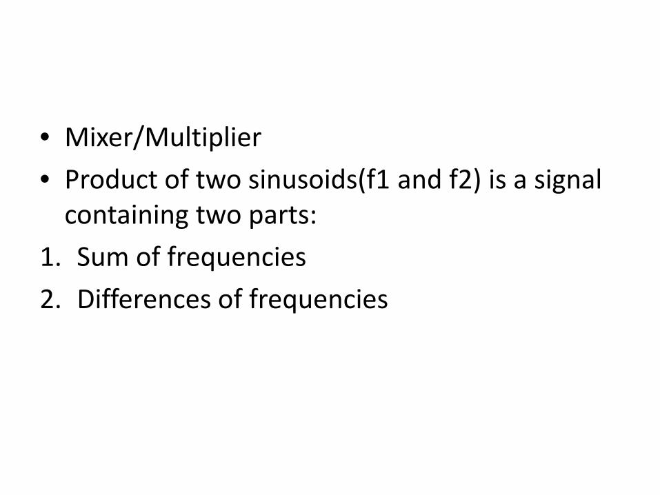
• Mixer/Multiplier • Product of two sinusoids(f1 and f2) is a signal
containing two parts: 1. Sum of frequencies 2. Differences of frequencies


• Our Mixer will multiply the incoming signal with a square wave, which will create some problems, more on this later.


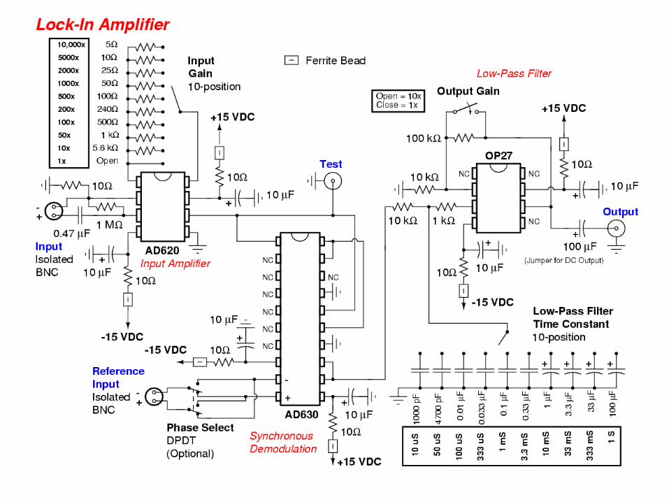
Home Brew Lock-in Amplifier
• Four Parts: 1. Input Amplifier (AD620) 2. Mixer (AD630) 3. Low Pass Filter (Single Pole) 4. Output Amplifier (OP 27)

Noise and Other Terms
• Many types of noise but we have restricted ourselves to White Noise and 1/f noise.
• Inherent Worst noise figure of 75.83μV. • Dynamic Reserve= Ratio of Overload level of
noise to full scale input signal • SNR:Signal to Noise Ratio • 1MHz unity gain bandwidth of AD620

• Measurement of resistance of a wire

Y-axis: Voltage drop across wire in mV. X-axis: Amplitude of Source

• Commercial:22.3mOhm • Homebrew:14m Ohm • Erroneous Results.

Malus’s Law Verification

• Main Test was Malus’s law which states : • According to malus, when completely plane
polarized light is incident on the analyzer, the intensity I of the light transmitted by the analyzer is directly proportional to the square of the cosine of angle between the transmission axes of the analyzer and the polarizer.i.e I ∞ cos2θ

Results
• Large Deviation from the Commercial Lock-ins. • Cursory measurements to be avoided. • Further Testing required. • Improvements like PLL, dual phase,phase
shifter etc. can be made.

• This year, with some little tweaks, better results have been obtained.
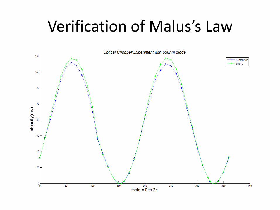
Verification of Malus’s Law

Two Main Problems
• Line Hum reduction • Proper reading of photodiode output through
trans-impedance Amplifier

Week 1
• Observed a 100mV amplitude 50Hz wave at input even though the circuit was powered off

Hum

• Natural Option to deal with it was a notch filter
• But Notch are RLC filters, and inductors must be avoided in precision circuits.
• An inductor-less notch is a ‘twin-tee’ notch.


• Recursive Problem: We need a high Q ‘Twin-T’ notch to remove hum for building a lock-in amplifier, which is itself a very-high-Q notch.
• Line-in option in SR510 for hum removal. • Low Q notches were made.(Max. depth of
28.8dB) and using AD620 as op-amp instead of UA741 for high precision.
• Bandwidth was very high(of the order of 100kHz) • Q=w/B.W


• The AD630 data sheet mentions recovering 50uV of signal from 100dB of noise(5V).
• So I tried this circuit:

• Maybe the AD630 would take care of hum itself and I won’t have to AC amplify the signal.
• But there was another problem with my measurement of photodiode output.
• I was also exploring the option of shielding.

Week 2
• Stray thoughts on the reasons for wrong results of Optical Chopper experiments, overloading, non-linearity, PLL?
• Put the circuit in an Al-foil enclosed box. Hum was reduced but still observed funny effects. The Al-foil was not grounded.

Al Foil

An Eid spent in the Car
• Jana, Eid par aana, phir ghar jana, phir wapis Lahore Aana.
• Talked to some experts, they told me to ground the foil.

Hum with Al shielding

Ground the Foil at various Points to ensure uniform grounding

Week 3
• Read more upon noise removal and proper grounding.
• Rarely Asked Questions on Bread boarding. • Basic Principle of Noise Reduction: • COPPER IS NOT A SUPERCONDUCTOR


• Grounding the foil reduced Hum to 2-3mV from 50mV.
• Twisting cables are better than straight ones. • Differential Input: Required or not.

Weekend
• Met Prof. Shameem: Says that life is a tragedy, we will never know the truth and will die hunting for it.(So is the case of Noise with precision circuits).

Week 4
• Studied AD630 in more detail, resistors reducing input bias current, frequency compensation.
• Saw other works using Ad630 as a lock-in. • Realised all of them were working on mV scale, not uV. • Accurate voltage readings till 1mV with simple voltage
dividers. • In one project, PSPICE simulation could provide
maximum SNR of 45dB, instead of the data sheet’s 100dB.
• Zeroing the phase of SR510.


Week 5
• Trans-Impedance Amplifier • Photo Diode Model:


Basic Trans-Impedance Amplifier
• Gain is equal to Rf (V/A or Ohm)

Barkhausen stability criterion

Compensation Feedback Capacitor

Directly Connecting Photodiode output to Oscilloscope

Ringing and Oscillation

After adding feedback capacitor

Results
• The 4mW He-Ne Laser was used first. The results were a bit eerie owing to the unstable output of the Laser.


• Then tested with 650nm laser diode which has more stable output.
• Results are pretty good and the readings match with a maximum difference of 5mV at the peak of the curve.


• Started Afsana course: Convinced my mom I wasn’t in bad company.
• Too much noisy post-colonialism and Saidian secularism. I can’t hear myself!

What do the measurements mean?
• Lock-In measures rms value of that component of input signal whose frequency is equal to the reference frequency.
• If input is a square wave of 1KHz, for example, the SR510 would measure the rms value of the first harmonic of the square wave.
• This is accomplished by to sine wave multipliers. • Walsh demodulator circuits approximate sine-
wave multiplication

• The home-brew lock-in is a bit old-fashioned. • It multiplies the input signal with a square
wave. • Thus it multiplies the input signal with all of its
harmonics. • This could generate spurious outputs if a
heavy noise component resides at one of the harmonics.


Phase Shifter

Phase Shifter • Unity Gain for all frequqncies • Phase shift= pi-2*arctan(wRC) where w is signal
ferquency • It’s unlike a PLL which keeps a constant phase
difference between input and output. • Can be used in two ways: 1. Vary the phase until DC output goes to maximum 2. Measure the value at one particular phase, and then
add a 90 degree shift and then measure the value at that phase. The root of the sum of squares of these values should be equal to maximum value measured by method 1.

Phase Shifter Used in Homebrew Lock-in


PCB
• Tried to follow the Noise-reduction techniques in routing.
• 0.76 mm thick Al box for shielding.

PCB Pics


Constant Current Source
• Maintains constant current by varying the voltage across a load, or by varying the load across which there is a constant potential drop.
• Maximum Current allowed 10mA. • Temperature Co-efficient of (227/R)uAmp per
degree centigrade. • Can also be used in temperature
measurement applications.


Thank You Physlab People!
• For providing me the opportunity to work on such a fascinating project.
• For helping me out with the tiniest bits. • For making my summer productive, or I’d still
be playing FIFA 13. • For providing me the opportunity to discover
the clean signals beneath the noise of Lahore, its people and its rickshaws!
