how to guide - mojo3d connections cable how to guide - mojo3d connections.pdfhow to guide: mojo3d...
TRANSCRIPT
For more information:
www.AgGuidance.com
Page 1/12 v1.5
HOW TO GUIDE: HOW TO GUIDE: HOW TO GUIDE: HOW TO GUIDE: mojo3D Connectionsmojo3D Connectionsmojo3D Connectionsmojo3D Connections
This document describes all of the possible connections for the mojo3D
system including CAN bus accessories.
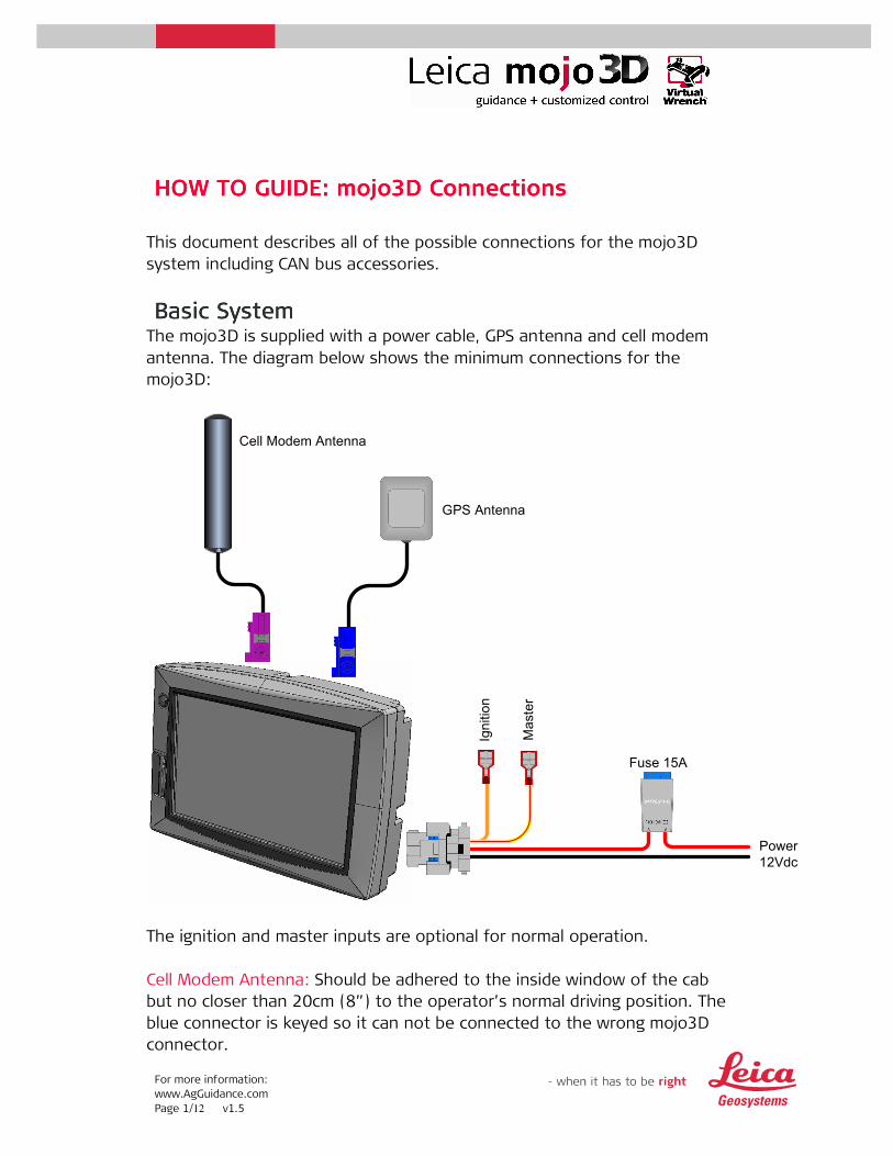
Basic SystemBasic SystemBasic SystemBasic System The mojo3D is supplied with a power cable, GPS antenna and cell modem
antenna. The diagram below shows the minimum connections for the
mojo3D:
Cell Modem Antenna
GPS Antenna
Power
12Vdc
Fuse 15A
Ignition
Master
The ignition and master inputs are optional for normal operation.
Cell Modem Antenna: Should be adhered to the inside window of the cab
but no closer than 20cm (8”) to the operator’s normal driving position. The
blue connector is keyed so it can not be connected to the wrong mojo3D
connector.
For more information:
www.AgGuidance.com
Page 2/12 v1.5
GPS Antenna: Should be mounted to the roof of the machine on the centre
line using either the magnetic mount or the supplied tape. The violet
connector is keyed so it can’t be connected to the wrong mojo3D RF
connector.
Power: Must be connected to a permanent 12Vdc power source capable of
delivering a constant 2A. The red wire is positive 12V while the black wire is
ground. The Orange ignition wire may be connected to a switched ignition
power source to automatically power the mojo3D on and off with the
machine.
Master Input: The optional master input may be connected to an external
switch for remote operation of coverage function. The master input should
be 12V when on and ground or floating when off.
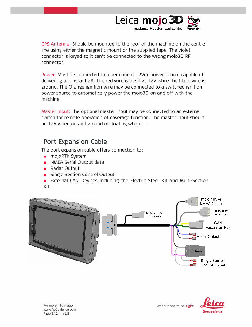
Port Expansion CablePort Expansion CablePort Expansion CablePort Expansion Cable The port expansion cable offers connection to:
���� mojoRTK System
���� NMEA Serial Output data
���� Radar Output
���� Single Section Control Output
���� External CAN Devices Including the Electric Steer Kit and Multi-Section
Kit.
For more information:
www.AgGuidance.com
Page 3/12 v1.5
mojoRTK / NMEA0183 Output: The short D9 connector serial data output
port is used to connect to either the mojoRTK console or provide standard
NMEA0183 data output to external 3rd party devices.
A mojoRTK External Control Cable is required to connect to the mojoRTK
console.
CAN Port: The expansion bus connector is the CAN port used to connect to
the Electric Steer Kit and/or the Multi-Section Kit.
Radar Output: The Radar output simulates a ground speed radar signal to
connect to 3rd party devices that can receive a radar input. The Black wire is
ground while the blue wire is the radar variable frequency output. The
output frequency is 26.11Hz/Km/hr (42Hz/mph) and receiving devices
should be setup for this scale.
Single Section Control Output: An isolated switched output via a relay is
provided for single section control. This switch is provided by the two grey
wires. Up to 30A can be switched through the relay to power 3rd party
equipment.
For more information:
www.AgGuidance.com
Page 4/12 v1.5
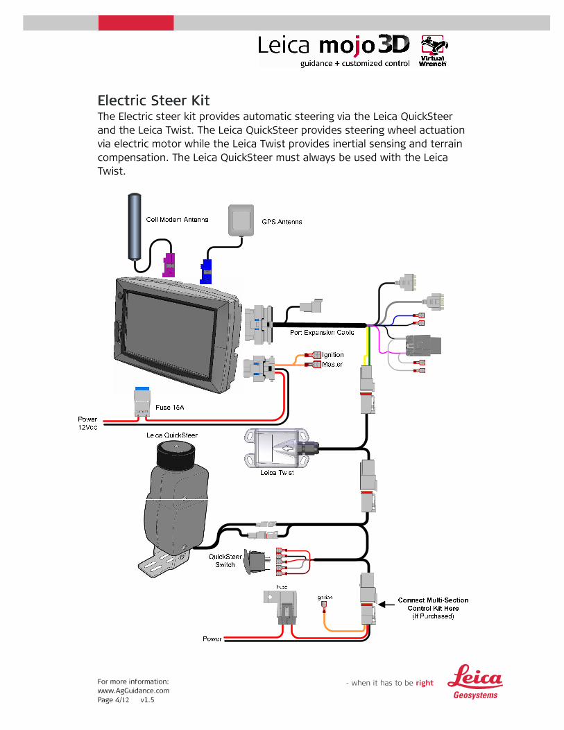
Electric Steer KitElectric Steer KitElectric Steer KitElectric Steer Kit The Electric steer kit provides automatic steering via the Leica QuickSteer
and the Leica Twist. The Leica QuickSteer provides steering wheel actuation
via electric motor while the Leica Twist provides inertial sensing and terrain
compensation. The Leica QuickSteer must always be used with the Leica
Twist.
For more information:
www.AgGuidance.com
Page 5/12 v1.5
Power: The power connection for the Electric Steer Kit should be able to
supply 5A continuous from a permanent 12V supply. If the Multi-Section Kit
is also being used then this connection must be able to supply 13A
continuous and the Multi-Section Kit must be connected closest to the
power source. A 5m (16.4’) cable is supplied so that direct connection to
the battery is possible if required.
The Orange ignition wire may be connected to a switched ignition power
source.
Leica QuickSteer: The QuickSteer is to be mounted to the steering column.
For details on how to install the QuickSteer using its Universal QuickSteer
Bracket consult the Leica QuickSteer User Manual supplied with the
product.
Note:Note:Note:Note: The following cables supplied with the QuickSteer are not required
for installation with the mojo3D:
• 676093: QuickSteer CAN Cable
• 676092: QuickSteer Generic Power Cable
These two cables are only supplied for connection to the mojoRTK system,
instead the QuickSteer should be connected to the QuickSteer CAN
interface cable only.
Switch: The guidance switch serves two functions:
���� Power Isolation for the QuickSteer
���� Steering Engage function
The wires on the QuickSteer CAN interface cable are numbered; these
numbers correspond to the numbered terminal pins on the switch.
The switch is a standard size and should fit into a spare switch location on
the machines operating panel.
For more information:
www.AgGuidance.com
Page 6/12 v1.5
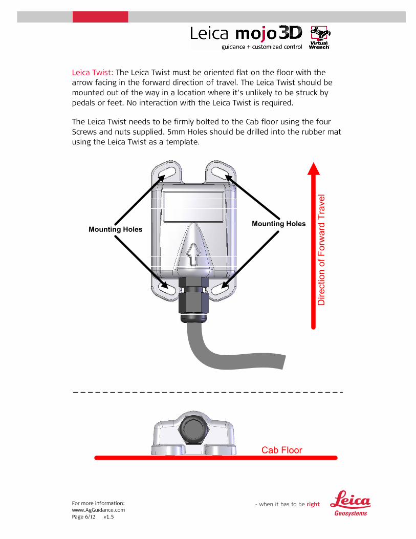
Leica Twist: The Leica Twist must be oriented flat on the floor with the
arrow facing in the forward direction of travel. The Leica Twist should be
mounted out of the way in a location where it’s unlikely to be struck by
pedals or feet. No interaction with the Leica Twist is required.
The Leica Twist needs to be firmly bolted to the Cab floor using the four
Screws and nuts supplied. 5mm Holes should be drilled into the rubber mat
using the Leica Twist as a template.
Mounting HolesMounting Holes
Direction of Forw
ard Travel
Cab Floor
For more information:
www.AgGuidance.com
Page 7/12 v1.5
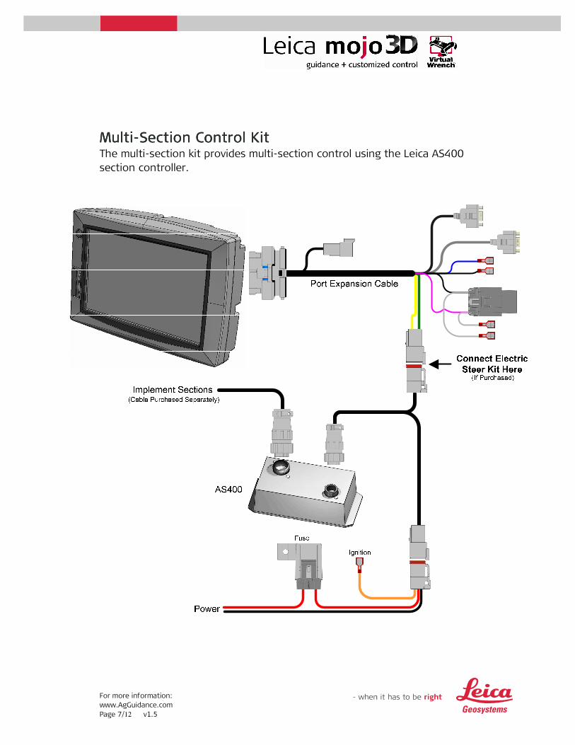
MultiMultiMultiMulti----Section Section Section Section Control Control Control Control KitKitKitKit The multi-section kit provides multi-section control using the Leica AS400
section controller.

For more information:
www.AgGuidance.com
Page 8/12 v1.5
Power: The power connection for the Multi-Section Control kit should be
able to supply 8A continuous from a permanent 12V supply. If the Electric
Steer Kit is also being used then this connection must be able to supply
13A continuous and the Multi-Section Control Kit must be connected
closest to the power source. A 5m (16.4’) cable is supplied so that direct
connection to the battery is possible if required.
The Orange ignition wire may be connected to a switched ignition power
source.
AS400: The AS400 section controller should be located in the cab and
provides up to 13 section control. For more information regarding the
AS400 mounting, section connection and other features please consult the
AS400 user manual.

For more information:
www.AgGuidance.com
Page 9/12 v1.5
Order NumbersOrder NumbersOrder NumbersOrder Numbers The following part numbers can be used when ordering the mojo3D and
accessories:
777532: Leica mojo3D Kit. Includes:
777535: Leica mojo3D Kit (US Version). Includes:
780161: Leica mojo3D Vehicle Switch Kit. Includes:
For more information:
www.AgGuidance.com
Page 10/12 v1.5
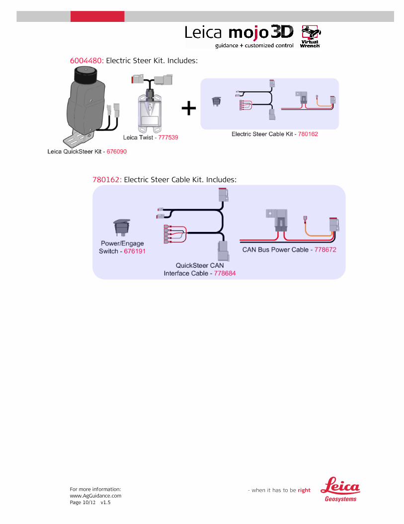
6004480: Electric Steer Kit. Includes:
780162: Electric Steer Cable Kit. Includes:
For more information:
www.AgGuidance.com
Page 11/12 v1.5
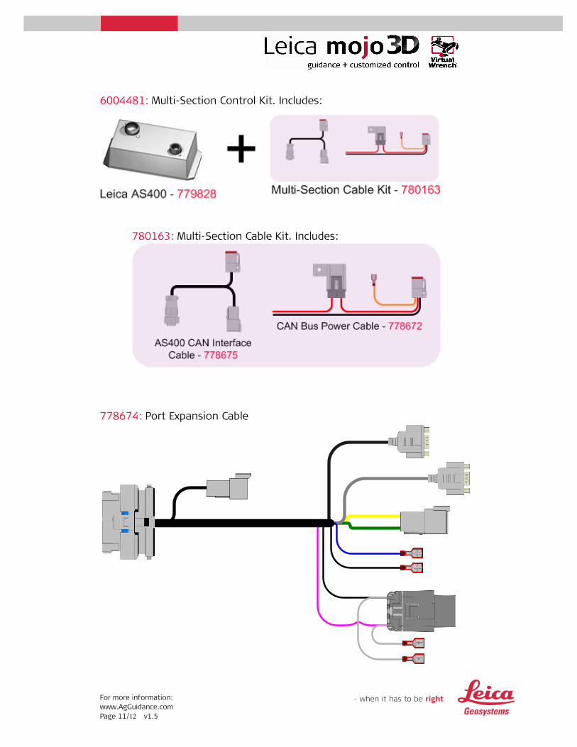
6004481: Multi-Section Control Kit. Includes:
780163: Multi-Section Cable Kit. Includes:
778674: Port Expansion Cable

For more information:
www.AgGuidance.com
Page 12/12 v1.5
675593: mojoRTK External Control Cable (Non-Australian Version)
675594: mojoRTK External Control Cable (Australian Version)