how to get your computer to control your layout
TRANSCRIPT

How to Get Your Computer to Control Your Layout
…plus other goodies
Using C/MRI and DCC

Seaboard Air Line – West Georgia Subdivision

What We’ll Discuss
• What C/MRI is• Why it’s not as complex as you’d think• Modularization of layout electronics• Documenting layout electronics• Planning layout electronics

Hopeful Takeaways
• Computer control is not difficult, and it really helps layout operation flexibility
• Modularization of electrical components can make layout wiring and maintenance easier
• It is possible to wire electrical panels without becoming a contortionist
• Planning and documentation of electrical systems is beneficial to any layout!

How C/MRI Works (Basic)
X

How C/MRI Works (Advanced)
DCCSystem
The Myths
• Computer control is just for geeks
• This is way too hard for anyone to understand• This requires programming skills
• Computer interface is only for large layouts• DCC can do everything
• None of this is true….

WHAT IS COMPUTER CONTROL?
• It’s NOT computer running trains – although that is possible
• It is computer controlling the layout infrastructure– Turnouts– Signals– Reversing Loops– Panel Displays– Animation & Lighting– As little or as much as you want….
• You could have it control trains… if you want to
• Don’t have to do this with DCC – can use DC and cab control too
• This complements DCC, does NOT replace it!

Why would I ever want a computer to control my layout?
• Simplicity of wiringEasy to establish standards
• Simplicity of User InterfaceEasy to use, easy to understand control panels
• Flexibility of design Wire it once, change the way it works later.
• Ability to expand capabilitiesCTC and Visitor Modes – disable panels from curious visitors!
• Computer does the hard workEasier to modify logic than change wiring
• Lots of stuff can be done with low voltage wiringCat 5 cable (8 conductor network wire) is relatively inexpensive
• System is ModularYou can replace or change modules without destroying the layout
• Used Computers are CHEAP (or free)

Other Advantages
• Forces you to use standards (that’s good-saves time)• Allows modular design of electrical components
(assemble on workbench!)• Encourages documentation of the layout• Uses that old computer• Use that broken computer’s power supply• Change things with software, not a soldering iron• You don’t have to know the ‘turnout number’ to throw the
turnout! (good user interface)• Separates propulsion control data from layout control
data

Requirements
• Computer (PC – Macs have been used)• Railroad• Wiring Standards (yes, planning ahead)• Ability to document what you do• Enjoyment of electronics • Soldering skills (optional)• Some programming skills (optional)

Yeah, But I don’t like complexity
• Start with controlling turnouts and panels
• Control animation• Then add occupancy detection
• Add signals• Set up CTC system (use monitors for panels)
• Control trains directly• Control room lighting
Implementation can be phased

Yeah, But I Can’t Program
• Ever heard of the JMRI project?– Java Model Railroad Interface– Public domain code– Setup your layout via an interface, no coding
necessary– Works with DCC and C/MRI– Designed/maintained by model railroaders– See: http://jmri.sourceforge.net/
• But if you like it Visual Basic works well too (or BASIC or GWBASIC or PowerBasic or C or whatever) – a small amount of sample code shows up in a few slides…

This stuff has got to be expensive!
• Like anything in model railroading, good stuff is not cheap
• BUT … this is not expensive• The SMINI costs about $1.40 per I/O line if
you buy the parts yourself.• The SMINI is about $1.50 per line as a kit• It costs about $2.50 per line assembled

What’s the bottom line ?
• If you build it yourself, automating a tortoise costs (bottom end) $4.20. Plus toggle switch and wire.
• If you use a pre-built system, that’s $7.50.• An accessory (stationary) decoder costs
about $8.00 per turnout.• Plus - using C/MRI adds nothing to the
DCC data congestion on the track.

Examples
Dr. Bruce Chubb (creator of C/MRI) at his CTC Panel

Examples
Jeff Warner's PRR/RDG/WM South Central Region - Etters PA

Examples
Ed Crone has a TOTALLY automated layout. It can run for 20 minutes on its own and includes about 24 coupling and uncoupling moves. – OK, maybe overkill.

My Computer Interface(still under construction)
OK, How do you do this?
• Let’s start simple – panel controls for turnouts.
• On the layout:– Use tortoise machines (others can be used)– Use toggles or pushbuttons for panels– Position lighting on panel is optional (but it
sure looks nice!)– Bring wiring to central location – or several
localized nodes.

What are the pieces?
Five basic components:
• Serial/RJ45 converter board (got to have this!)• Controller
– Can be USIC (universal serial interface controller)
– …or … SMINI (my preference)
• Some sort of input/display device (i.e. panel)• Computer
• Power Source

How the pieces hook together
ComputerRS485
Converter
SMINI
Panel Turnouts
OtherSMINIs
SignalsDetectors
Note: Power Supply not shown… everything needs juice!
DCC System
RS485 wire
RS485 wire
Cat5 Wire Cat5 Wire Cat5 Wire Cat5 Wire
Serial Cable
Serial Cable

RS485 Converter
This fits between a serial port on the computer and the C/MRI controllers – you only need one.

Power Supply
• This ABSOLUTLELY MUST be a switching power supply (like computers use.)
• Transformers have voltage levels that dwindle as load increases – that’s why switching supplies are needed.
• This is, after all, a computing device – and it needs steady juice.
• My 15 year old power supply handles 5 Volts at 23 Amps, and 12 Volts at 9 Amps. Enough for about 10 SMINI’s and 150 turnouts.
• It cost me nothing! (except for the fuses)

Sample Power SupplyOld computer power supply with added toggle switch for on/off
This is a close up of the fuses. Note the power resistor initially used to “kickoff” the supply. After 1 SMINI andseveral turnouts were added, this wasremoved.

SMINI
An SMINI has 24 inputs and 48 outputs
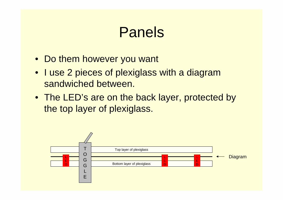
Panels
• Do them however you want
• I use 2 pieces of plexiglass with a diagram sandwiched between.
• The LED’s are on the back layer, protected by the top layer of plexiglass.
Bottom layer of plexiglass
Top layer of plexiglass
LED
LED
LED
Diagram
TOGGLE

Panels

The Panel ‘Guts’
Only connections to the SMINI are needed…

Panel Toggle Switches
• Used for turnouts and other accessories
• Low power SPST toggles are all that is needed• Toggle switch grounds an input tab on the SMINI
• Computer sees it is grounded, and throws associated turnout (that is if you want it to!)
• Computer could say “this is an open house” and ignore the toggle switch changes….
• Could be done with a pushbutton too… just a minor difference in the computer code.

Panel LED’s
• Supply voltage to LED from a +5V source (a resistor will be needed)
• Hook other end of LED to output pin of SMINI. (output meaning that pin is controlled by the computer)
• If computer wants the LED to glow, it grounds that output pin.

OK, this is as about as technical as it’s going to get…..
LED
Resistor
SMINI Outputs
SMINI Input
+5v
Toggle
Ground
How outputs and inputs are wired to components
+5-20vRelay

For The Geeksa bit of control logic code….
Visual Basic code that looks at the position of the toggle switch ‘SM101’, and sets turnout ‘TM101’ to the appropriate orientation. (the constant values of TUN and TUR are defined elsewhere)
If SM101 = 1 Then
TM101 = TUN
Else
TM101 = TUR
End If
Visual Basic code that looks at the position of the toggle switch ‘SM101’ and sets the 2 color panel display LED’s appropriately to indicate the direction of throw. (the values of the constants REDGRN and GRNRED are defined elsewhere and don’t change)
If SM101 = 1 Then
LM101N = REDGRN
Else
LM101N = GRNRED
End If
And yes, there is code to receive the setting of the toggle, and send the turnout and panel light commands… but that is easy, doesn’t change with any logic modifications, and way beyond the scope of this presentation.

Yeah, but I could control the turnout with a DPDT switch to the panel and control the
LED directly!
• Yes you could
• However… the toggle switch is ALWAYS active, even when visitors ‘bump’ into them.
• If you disable direct wired toggles, you disable the panel lights
• With C/MRI, you can disable the toggles, and still show the lights!

Other Useful Components
• Turnout Control (SMC12)• Occupancy Detection (DCCOD)

SMC12
• A standard board that allows single wire control to motorized turnouts.
• Feed it 12 volts• An output is polarized one way when the control
lead is grounded• It is polarized in the opposite way when the
control lead is open• The board can be ‘broken up’ for local control• The board can be modified (hacked) to be used
as an infrared block detection controller… but that’s another story…

Turnout Control
SMINISMC12
SMINIOutput
Tortoise #1

SMC12 Turnout controller
SMC12 hooked to a telco distribution block

Occupancy Detection
• Done with NO connections to track power (none – zero –zip…)
• Uses current sensing coils to keep logic electrically isolated and independent from track current.
• Block supply current goes through coil, inducing current and activating the detector
• Adjustable sensitivity• Cheap (about $11/block)• Hooks directly to SMINI• You must have a blocked layout• It can work with CAB control layouts• NEVER, EVER hook track voltage to SMINI

Occupancy Detector
The numbers indicate the time (in seconds) that the detector delays indication of occupancy or dropping occupancy (controlled by resistors).
Note the coil at the right – the detector causes no track voltage drop.
Plug at right allows connection to a motherboard

Lots of hardware – so what?
• The SMC12 and DCCOD are both useful on anyrailroad – even without using a computer.
• The SMC12 allows single wire control of stall switch machines (a common ground and power supply is fed to the board – it’s gotta eat…)
• The DCCOD detectors are nice since they are isolated from track current – and cheap. ($11 per block - $12.40 if you use a mother board)

MAKING WIRING MODULAR
• C/MRI lends itself to modular construction• You can use this for ANY layout electrical
panels• Simplify and standardize electronic
devices• Allows bench built components• Allows the use of spare components.

Simple Control Station for Turnouts and Panels (not hooked up!)
Panels are created on the workbench – and wired so theycan be modified while sitting in a chair next to the layout(lots of slack for the cables is necessary for that – but worth it!!!!

Panel/Turnout control hooked up
Note spare terminal at lower right – destined for occupancy detection
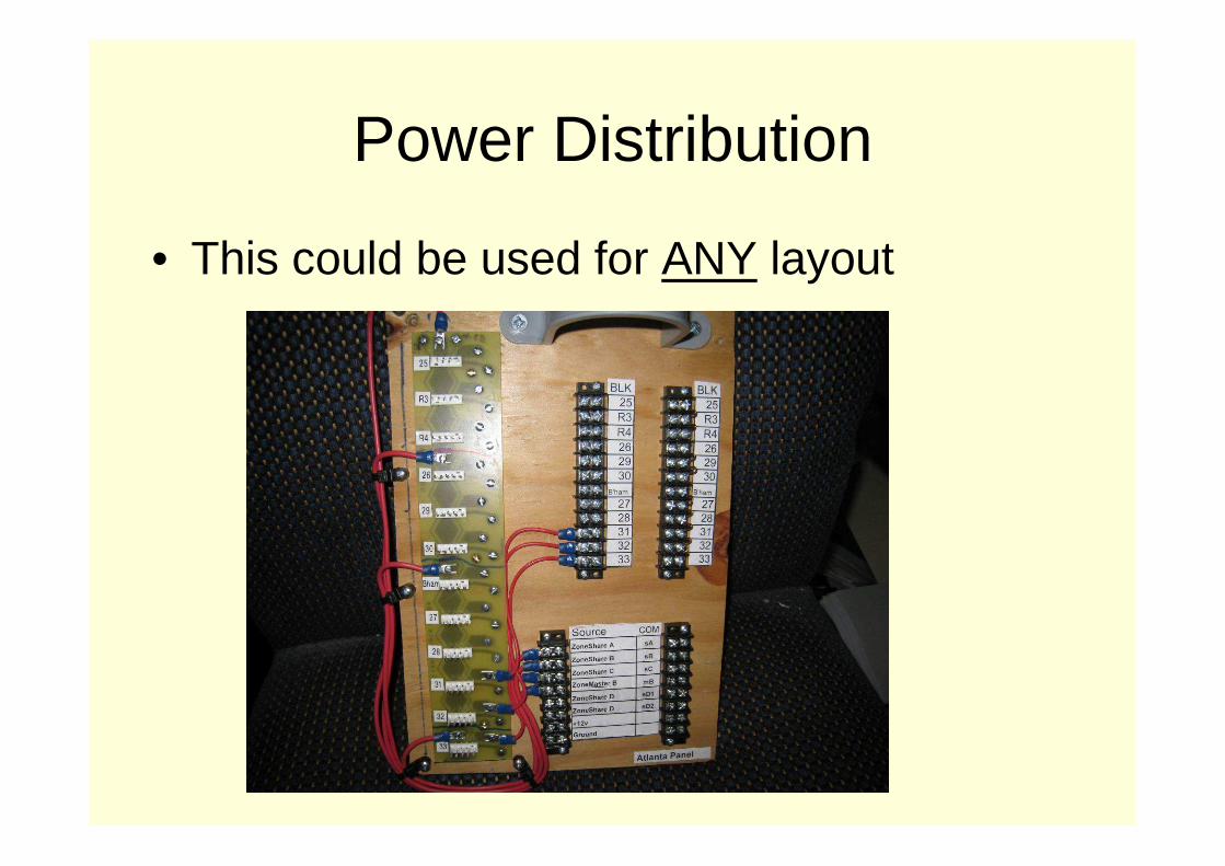
Power Distribution
• This could be used for ANY layout

Confession Time
• The distribution node was built at the workbench
• But…• It’s not hooked up• Here’s what it looks like in practice• (by the way, it could be easily disconnected,
reconnected or replaced…)
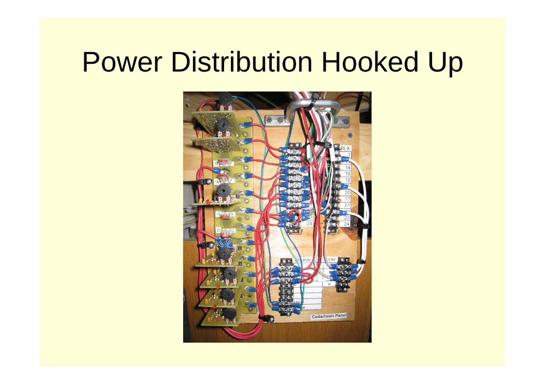
Power Distribution Hooked Up

Yes, you can modularize DCC too.
• This is a board containing 3 CVP Products AD4 DCC accessory decoders. It uses RJ45 connectors to link to panels for local turnout control, and seriouslyoversized barrier terminal strips for turnout connections.
• This device controls 12 turnouts – 8 Tortoise and 2 solenoids• The AD4 controllers were built from kits• Note that the controllers can be replaced via sockets• This was built years ago on a coffee table accompanied by some good brew

Accessible Pieces
• I like to work on the layout either standing up or sitting in a chair.
• Not lying on my back under the layout.• So the control modules can be moved for
easy maintenance.

Simplified Maintenance
I don’t like crawling beneath the layout to do detailed wiring…so long cables are used
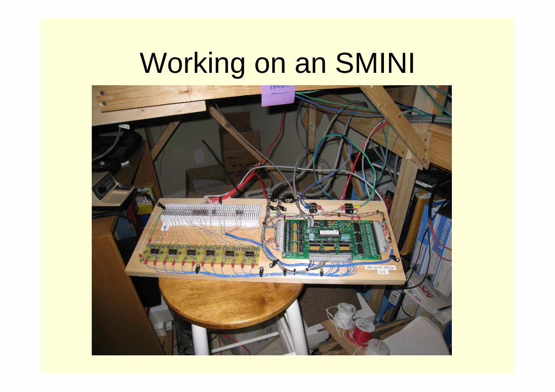
Working on an SMINI

Useful Tools
• A Good Spade Lug Crimper
• Molex Connector Crimper (Waldom)
• A GOOD wire stripper (avoid cheap ones)

What else can be done?
• It get more complex if you want multi color target signals, but the SMINI will drive RYG LED’s!!!
• If you want to flash panel lights, you do it in the code. Not really that difficult.
• You can run relays too (up to 20v coils)

Gotcha’s
• You MUST have a good power supply. It must be computer grade. It MUST be a switching power supply. Power packs will not power CMRI.
• The computer must be running the layout software if you want to run the layout. (but it can be wired so that this is not necessary…)
• As in any situation, it’s good to have spare parts. (things only break when visitors are around.)
• It requires some planning and documentation (which should be done anyway…)

Stuff I’ve Learned
• Yes, you can do it all with one power supply – after all, computer power supplies run about 250 watts+ … thought I’d need 2 or 3.
• When providing +5v and +12v from a central location … WIRE SIZE REALLY MATTERS!!! 10 or 12 gauge wire is a good idea since SMINI’s minimum voltage is 4.8 v. Check the voltage at the controller location with everything running.
• Be REAL careful when putting IC’s into their sockets (nuff said…)• Use a soldering station – it can save $$$ in fried parts• Use strain reliefs on ALL connections• Label your wires!• An SMINI costs about $100 if you order the stuff yourself.• An SMC12 costs about $30• An occupancy detector is about $11• This makes control panels very easy to wire (and changeable)

DOCUMENTATION
• Do it to even if you don’t use C/MRI• Document and plan in advance• Don’t do this just to meet some
requirement… do it to save your sanity• It is EASY to wire something from a plan,
as all you need to do is hook up the wires

Sample Hookup DocumentationSMINI #2 Inputs - (Goodyear Cord, Cedartown and Polk Layover Panels)
Card 2 Bit 66 Blk Aspect Panel Cbl Color Stripe
1 1-1 PB209 Button Rem1 Goodyear 1 Grey Main East
2 1-2 PB210 Button Rem2 Goodyear 1 Green Black Siding East
3 1-3 PB211A Button Rem3 Goodyear 1 Orange Black Wye East
4 1-4 PB212 Button Rem4 Goodyear 1 Red Black Siding West
5 1-5 PB213 Button Rem5 Goodyear 1 Yellow Black Main West
6 1-6 PB211B Button Rem6 Goodyear 1 White Wye West
7 1-7 SB208 toggle Rem7 Goodyear 1 Yellow Pow er Plant Turnout
8 1-8 SM408 toggle Rem18 Cedartow n 1 Blue White Cedartow n East
9 2-1 SM409 toggle Rem19 Cedartow n 1 Green White Cedartow n Industry 1
10 2-2 SM410 toggle Rem20 Cedartow n 1 Red Cedartow n Industries Multi
11 2-3 SM411 toggle Rem21 Cedartow n 1 Red White Cedartow n West
12 2-4 SM412 toggle Rem22 Cedartow n 1 Orange Cedartow n - PROGRAMMING
13 2-5 PM301 Button Rem33 Layover 1 Brow n Polk Layover Main Button
14 2-6 PM314 Button Rem34 Layover 1 Green Polk Layover Siding Button
15 2-7 AT301 Rem35 Layover 1 Black Polk Layover Automode
16 2-8 -spare- 1 Pink
17 3-1 IR Detector Loc IR01 n/a Polk Layover
18 3-2 IR Detector Loc IR02 n/a Polk Layover
19 3-3 IR Detector Loc IR03 n/a Polk Layover
20 3-4 IR Detector Loc IR04 n/a Polk Layover
21 3-5 Occ Detector Loc DCCOD01 n/a Green White Polk Layover Block #1
22 3-6 Occ Detector Loc DCCOD14 n/a Brow n White Polk Layover Block #14
23 3-7 Occ Detector Loc DCCOD13 n/a White Brow n Polk Layover Block #13

Turnout Wiring Documentation Example
To Tortoise
FrogN S
To Track
2 341 8
+12v(use without
SMC12 controller)
Ctl1 Ctl2
Spares(track powerfeeders)
Resistors used in Absence of SMC12
White w/Brown Stripes
Blue w/ White Stripes
Brown w/White Stripes Orange
w/White Stripes
White w/Orange Stripes
Tortoise Cat5 Connection Spare Leads:
White w/Blue Stripes - #6Green w/White Stripes - #5White w/Green Stripes - #7
Tortoise Connections
Pin 1 Orange/White
Pin 2 White/Brown
Pin 3 Blue/White
Pin 4 Brown/White
Pin 5 Green/White
Pin 6 White/Blue
Pin 7 White/Green
Pin 8 White/Orange
• Note: Pre wiring a Tortoise with Cat5 wire is not an original idea – I got the concept from Bob Young and modified it a bit…

Why do all this documentation?
• Reduces errors• Allows thinking before doing• Makes assembly MUCH easier• Makes bug fixes easier• Makes modification and update easier

• Everything is modular and expandable• Group components in logical locations• Plan for expansion and future use• Keep it neat as possible• Document what your going to do before
you do it!• Allow room for changes
PLANNING THE SYSTEM

Distributed Controls
SMINI 2
SMINI 1
SMINI n
ComputerControl Panels
Turnouts
Control Panels
Turnouts
Signals
Occupancy
Signals
RS485
RS485
RS485
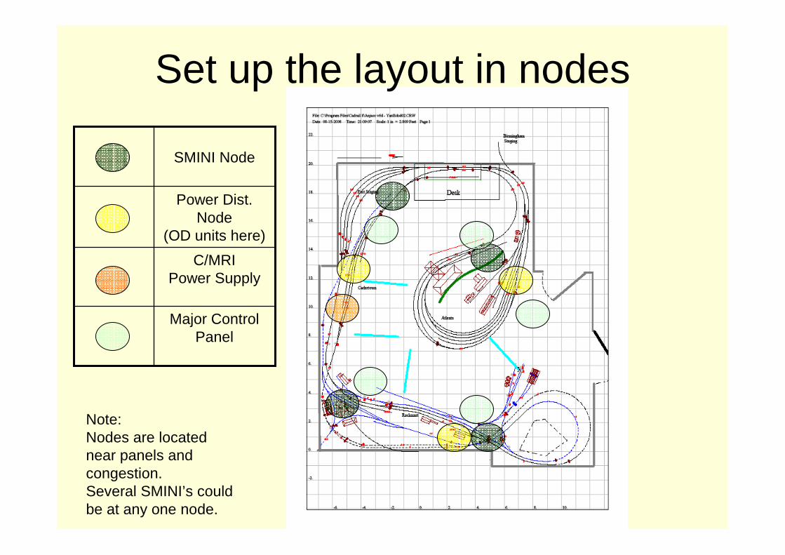
Note:Nodes are locatednear panels and congestion.Several SMINI’s couldbe at any one node.
Major Control Panel
C/MRIPower Supply
Power Dist.Node
(OD units here)
SMINI Node
Set up the layout in nodes

Where do you get this stuff?
• You can build it yourself from parts• You can order and build kits• You can order completed components• You could even etch your own boards if
you really wanted to.

Conclusion
• Computer control is not as difficult as you’d think
• Computer control allows for significant layout operation flexibility and expansion
• Making modular components makes wiring easier
• Document wiring before installation
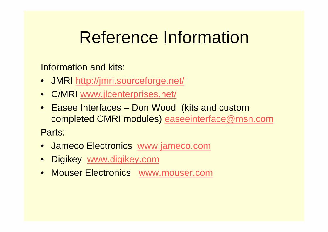
Reference Information
Information and kits:• JMRI http://jmri.sourceforge.net/• C/MRI www.jlcenterprises.net/• Easee Interfaces – Don Wood (kits and custom
completed CMRI modules) [email protected]:• Jameco Electronics www.jameco.com• Digikey www.digikey.com• Mouser Electronics www.mouser.com

Seaboard Air Line – West Georgia Subdivision