how gpon deployment drives the evolution of the … · how gpon deployment drives the evolution of...
TRANSCRIPT
How GPON Deployment Drives the Evolution of the
Packet-Based Network
FUJITSU NETWORK COMMUNICATIONS INC.2801 Telecom Parkway, Richardson, Texas 75082-3515Telephone: (972) 690-6000(800) 777-FAST (U.S.)us.fujitsu.com/telecom
1
IntroductionThe rollout of PON systems in the access market is bringing triple-play services—voice, video, and data—to the residential market. Telecom companies see PON as a means to offer video services and compete with cable/MSO companies. One of the main reasons making PON an effective access technology is that it can push downlink performance into the 2.5 Gbps range. The initial deployments of PON networks have focused on ATM-based BPON and EPON. However, BPON systems can only deliver 155 to 622 Mbps downlink streams while EPON systems are designed to deliver 1.25 Gbps connections only. As a result, many wonder if those PON systems can provide enough bandwidth for the emerging high bandwidth video applications such as HDTV. To address this concern, the FSAN/ITU-T committee has defined the G.984 specifications for the GPON operation.
What is GPON? GPON is the next-generation of PON that follows APON and BPON. The GPON standard G.984 has been approved by the ITU and supports higher data rates than earlier PON technologies, with 2.5 Gbps downstream (to the subscriber) and 1.2 Gbps upstream (away from the subscriber) over a reach of 60 km covering 32, 64 or 128 users per GPON interface. GPON provides several key advantages over other technologies [1]:
• A new framing mechanism called GEM can encapsulate both Ethernet and TDM traffic on a GPON link.• GPON supports both upstream and downstream traffic at gigabit speeds. The G.984 specification
defines GPON downstream speeds at either 1.25 or 2.5 Gbps and upstream speeds of either 155, 622, 1.25 or 2.5 Gbps (both big leaps over existing BPON systems). Most of the telecom service providers in North America have adopted 2.5 Gbps downstream and 1.25 Gbps upstream as the standard speeds for deployment.
• GPON provides better traffic management and security schemes with the new GPON MAC• GPON will be able to support the emerging demand for switched digital video and HDTV.
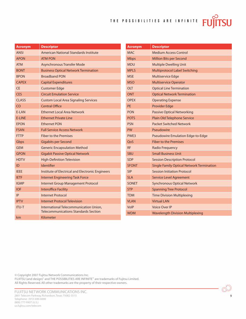
For your convenience, a list of acronyms can be found at the end of this document.
FUJITSU NETWORK COMMUNICATIONS INC.2801 Telecom Parkway, Richardson, Texas 75082-3515Telephone: (972) 690-6000(800) 777-FAST (U.S.)us.fujitsu.com/telecom
2
End Office
MPLS
Headendfor LocalContent
Internet
FLASHWAVE
4 1 0 0O L T
FLASHWAVE
4 1 0 0O L T
FLASHWAVE
6 1 0 0O L T
W D MClass 5
Softswitch
Video Servers
Local Video Routerand Modulator
IP Edge Router
(2) POTS(1) 10/100/1000Base-T Ethernet(1) CATV/MoCA (optional)
(8) POTS(1) 10/100/1000Base-T Ethernet(2) T1 LinesFor single Business applications
(24) POTS(12) 10/100/1000Base-T Ethernetor(12) VDSL2(1) CATV
SFONT
BONT
BONT
SFONT
BONT
BONT
SFONT
SBU
MDU
VoiceGateway
OpticalTransmitter
EDFA
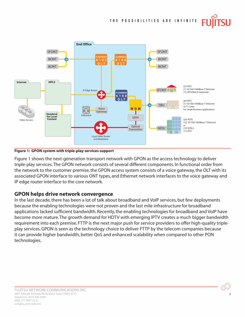
Figure 1: GPON system with triple-play services support
Figure 1 shows the next-generation transport network with GPON as the access technology to deliver triple-play services. The GPON network consists of several different components. In functional order from the network to the customer premise, the GPON access system consists of a voice gateway, the OLT with its associated GPON interface to various ONT types, and Ethernet network interfaces to the voice gateway and IP edge router interface to the core network.
GPON helps drive network convergenceIn the last decade, there has been a lot of talk about broadband and VoIP services, but few deployments because the enabling technologies were not proven and the last mile infrastructure for broadband applications lacked sufficient bandwidth. Recently, the enabling technologies for broadband and VoIP have become more mature. The growth demand for HDTV with emerging IPTV creates a much bigger bandwidth requirement into each premise. FTTP is the next major push for service providers to offer high-quality triple-play services. GPON is seen as the technology choice to deliver FTTP by the telecom companies because it can provide higher bandwidth, better QoS and enhanced scalability when compared to other PON technologies.
FUJITSU NETWORK COMMUNICATIONS INC.2801 Telecom Parkway, Richardson, Texas 75082-3515Telephone: (972) 690-6000(800) 777-FAST (U.S.)us.fujitsu.com/telecom
3
Also, traditional TDM voice traffic is moving to IP packets and TV signals are moving to digital MPEG packets. Most of broadband applications are packet-based, but have a much lower margin of profit for the service providers when compared to traditional voice services. Today’s overlay and traditional circuit-based infrastructure will become less optimal for the new packet-based services as the profit margin decreases. The vision of network convergence is coming back to reduce the cost of the existing network with the focus on packet-based technologies like bridging, VLAN, MPLS and PW.
GPON supports various residential and small/medium business applications. In the next section, a list of the services/applications for the GPON system will be discussed.
GPON Voice ApplicationsThere are two possible ways to handle voice services—H.248 or SIP. The H.248-based POTS voice service uses packetized voice frames and signaling to emulate a subscriber loop. An external or integrated voice gateway system maps packetized voice and voice-signaling frames to a GR-303 interface on Class 5 switches. The voice media channel is cut through all the way to the Class 5 switch as soon as the end user goes off hook. All call progress tones and CLASS features are served from the switch directly and passed transparently through the GPON access network.
When migrating legacy circuit-switched voice communication services to a packet network based on IP, SIP is the preferred call control signaling protocol for VoIP service. Telecom companies plan to eventually replace their current circuit-switched Class 5 switches with packet-based Softswitch platforms. Customer analog lines with RJ-11 connections from the ONT will perform a TDM-to-VoIP function. The VoIP will be carried over Ethernet and GEM in the GPON link and the voice traffic in IP packets across the network to the Softswitch. The primary role of SIP is to allow the caller and the called parties to contact each other and set up, modify, and end various types of communication sessions such as voice calls and video conferencing. The protocol components mentioned above deliver messages embedded with the SDP protocol to define their content and characteristics and complete a SIP session.
GPON Data ApplicationsThe primary GPON data application is high-speed Internet access via the 10/100/1000Base-T Ethernet connections from the ONT. These are standard data connections and are compliant with ANSI/IEEE 802.3.For business DS1 private line applications, GPON uses either CES or traditional SONET for transport. E-Line and E-LAN services are also possible business-oriented services that provide a point-to-point transparent Ethernet connection via the GPON system.
FUJITSU NETWORK COMMUNICATIONS INC.2801 Telecom Parkway, Richardson, Texas 75082-3515Telephone: (972) 690-6000(800) 777-FAST (U.S.)us.fujitsu.com/telecom
4
GPON Video ApplicationsThe delivery of television services over PON networks is accomplished using one of two approaches: video overlay or IPTV.
In the video overlay model, a separate 1550 nm optical wavelength is used on the fiber to transport video services between the OLT at the CO, or headend, and the ONT at the subscriber location. In the IPTV model, video services are transported as digital data in the same digital stream with other voice and data services on the fiber.
The video overlay approach uses WDM to combine the video and other optical transport signals onto a single fiber. The video wavelength (at 1550 nm) carries a broadband analog RF signal containing all TV signals and is independent of any other wavelength used for the PON itself. Some carriers initially chose to deliver broadcast video using an RF overlay network.
The second model for providing TV services is over an IPTV network. Signal transport is initiated automatically when a viewer selects a channel, triggering a request for service back to the system CO.
The IPTV model operates as a bandwidth-on-demand system. When more than one viewer on the PON is watching the same program, the signal need only be sent once over the PON, and multicast techniques are used to connect to the single transport stream as many subscribers as are viewing this signal. IGMP snooping/proxy is required to be supported in the OLT and ONT to provide bandwidth efficiency in the access network.
Also, this approach is more cost-effective than the overlay model because it does not require a separate optical overlay network and all the RF modulators and ONT receivers associated with it.
FUJITSU NETWORK COMMUNICATIONS INC.2801 Telecom Parkway, Richardson, Texas 75082-3515Telephone: (972) 690-6000(800) 777-FAST (U.S.)us.fujitsu.com/telecom
5
Transporting Multiple Broadband Services over the Metro and Core NetworkThus far we have discussed how voice, data and video packets are carried over the access portion of the network by GPON. Now the question becomes how those packets are handed off to the metro and core networks before they arrive at their destination. VLAN tagging and bridging are used as the initial deployment technologies to aggregate triple-play traffic. The ONT performs ingress traffic classification. Classification segregates ingress traffic into different traffic flows by VLAN ID. The flows can be further policed, and scheduled on the ONT with priorities for differentiated levels of services. The VLAN ID or the MAC address is used to identify the destination ONT or flow.
However, there is a limitation on protection, fault tolerance and scalability using this bridged Ethernet method to offer high-speed aggregation and triple play services to residential and business customers.
Bridged Ethernet networks rely on STP to recover from network failures. However, STP recovery time is on the order of seconds, not within the 50 ms window that SONET offers. An MPLS-enhanced metro Ethernet architecture can provide the carrier-grade resiliency with sub-50 ms fail over by the MPLS path protection approaches, global repair and fast re-route.
Bridged Ethernet networks rely on VLAN technology to separate broadcast domains and separate traffic among different customers. With a maximum of 4000 VLANs and limitations regarding the size of the MAC address table, there is a limit to the number of enterprise customers that can be supported in the metro network. MPLS enhanced metro Ethernet networks address these scalability issues by encapsulating the Ethernet frame in MPLS at the edge of the network.
Extending MPLS from the backbone to the metro will give service providers one unifying end-to-end network with better scalability, end-to-end QoS and OA&M diagnostics capabilities.
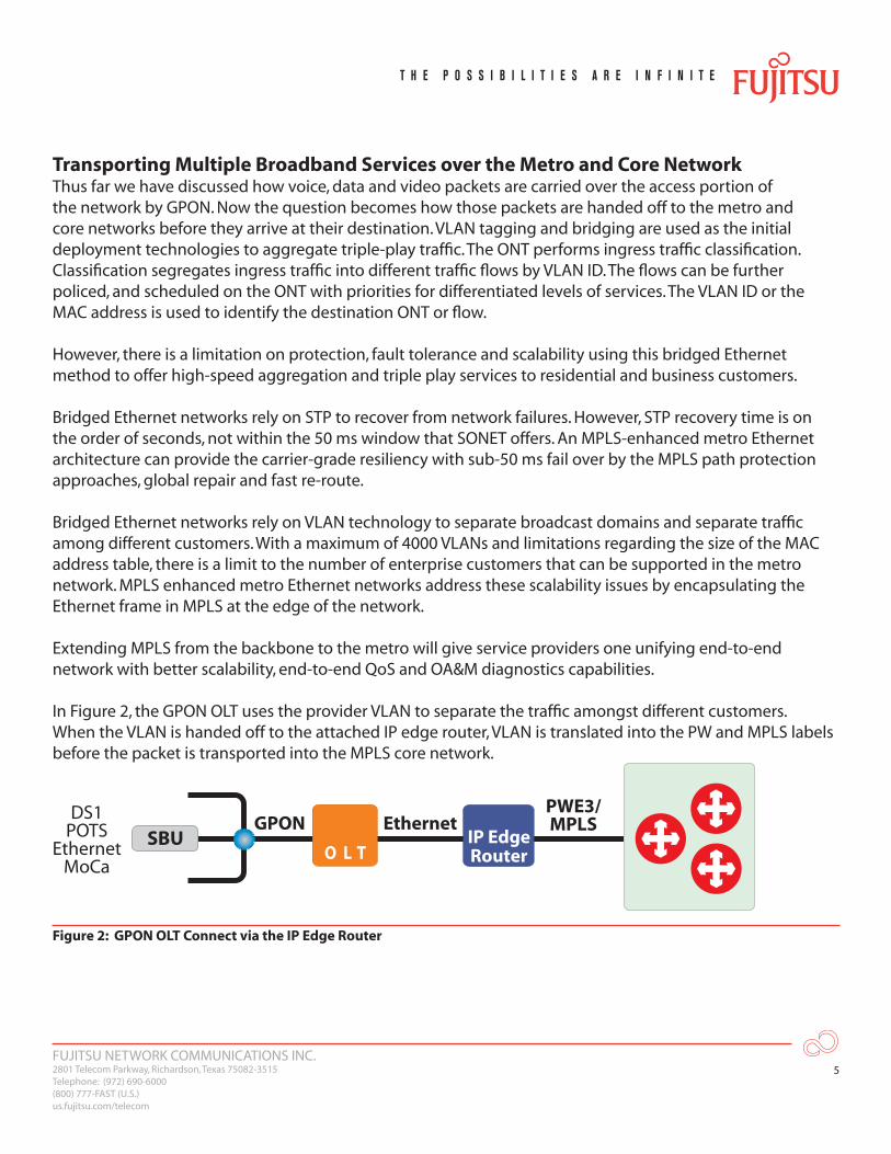
In Figure 2, the GPON OLT uses the provider VLAN to separate the traffic amongst different customers. When the VLAN is handed off to the attached IP edge router, VLAN is translated into the PW and MPLS labels before the packet is transported into the MPLS core network.
PWE3/MPLSEthernetGPON
DS1POTS
EthernetMoCa
IP EdgeRouterO L T
SBU
Figure 2: GPON OLT Connect via the IP Edge Router
FUJITSU NETWORK COMMUNICATIONS INC.2801 Telecom Parkway, Richardson, Texas 75082-3515Telephone: (972) 690-6000(800) 777-FAST (U.S.)us.fujitsu.com/telecom
6
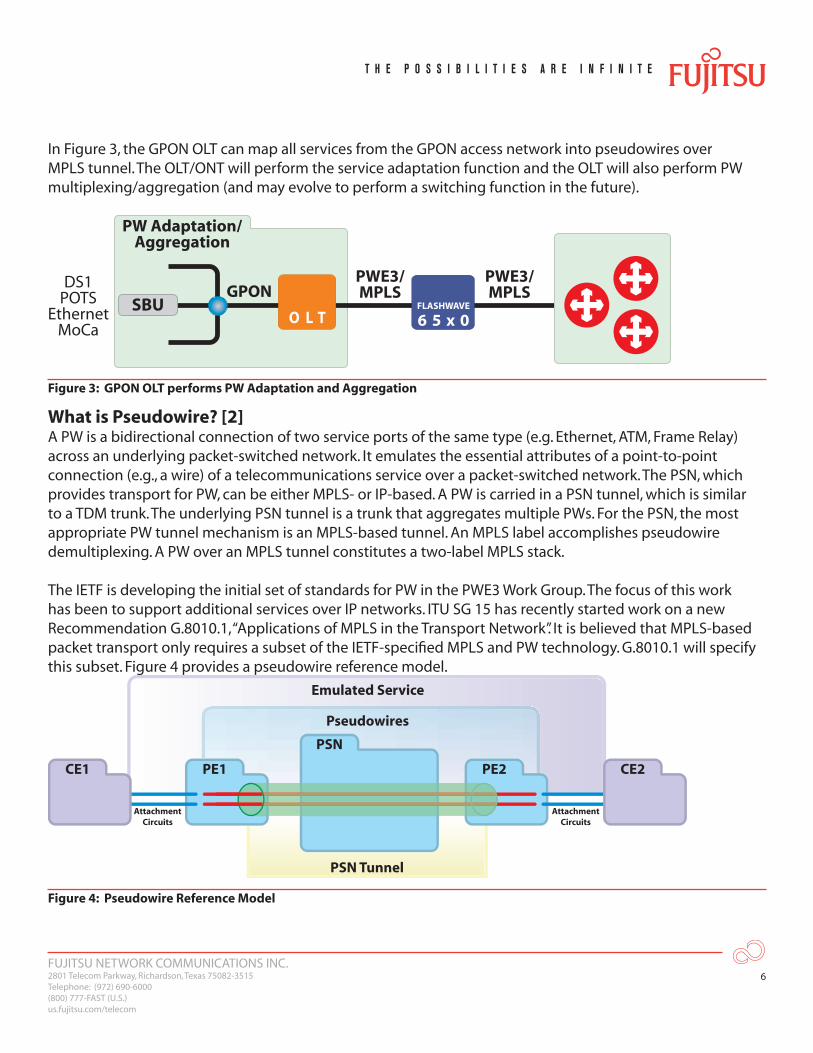
In Figure 3, the GPON OLT can map all services from the GPON access network into pseudowires over MPLS tunnel. The OLT/ONT will perform the service adaptation function and the OLT will also perform PW multiplexing/aggregation (and may evolve to perform a switching function in the future).
PWE3/MPLS
PWE3/MPLSGPON
PW Adaptation/Aggregation
DS1POTS
EthernetMoCa
FLASHWAVE
6 5 x 0O L TSBU
Figure 3: GPON OLT performs PW Adaptation and Aggregation
What is Pseudowire? [2]A PW is a bidirectional connection of two service ports of the same type (e.g. Ethernet, ATM, Frame Relay) across an underlying packet-switched network. It emulates the essential attributes of a point-to-point connection (e.g., a wire) of a telecommunications service over a packet-switched network. The PSN, which provides transport for PW, can be either MPLS- or IP-based. A PW is carried in a PSN tunnel, which is similar to a TDM trunk. The underlying PSN tunnel is a trunk that aggregates multiple PWs. For the PSN, the most appropriate PW tunnel mechanism is an MPLS-based tunnel. An MPLS label accomplishes pseudowire demultiplexing. A PW over an MPLS tunnel constitutes a two-label MPLS stack.
The IETF is developing the initial set of standards for PW in the PWE3 Work Group. The focus of this work has been to support additional services over IP networks. ITU SG 15 has recently started work on a new Recommendation G.8010.1, “Applications of MPLS in the Transport Network”. It is believed that MPLS-based packet transport only requires a subset of the IETF-specified MPLS and PW technology. G.8010.1 will specify this subset. Figure 4 provides a pseudowire reference model.
PE1 PE2
PSN
PSN Tunnel
Emulated Service
Pseudowires
CE1 CE2
Attachment Circuits
Attachment Circuits
Figure 4: Pseudowire Reference Model
FUJITSU NETWORK COMMUNICATIONS INC.2801 Telecom Parkway, Richardson, Texas 75082-3515Telephone: (972) 690-6000(800) 777-FAST (U.S.)us.fujitsu.com/telecom
7
A PW interconnects two attachment circuits of a chosen service across a PSN. An attachment circuit is a physical or virtual circuit that connects a CE node to a PE node. An attachment circuit can be an Ethernet port, a VLAN, a Frame Relay or ATM virtual circuit, a DS1, DS3, or a SONET STS-3.
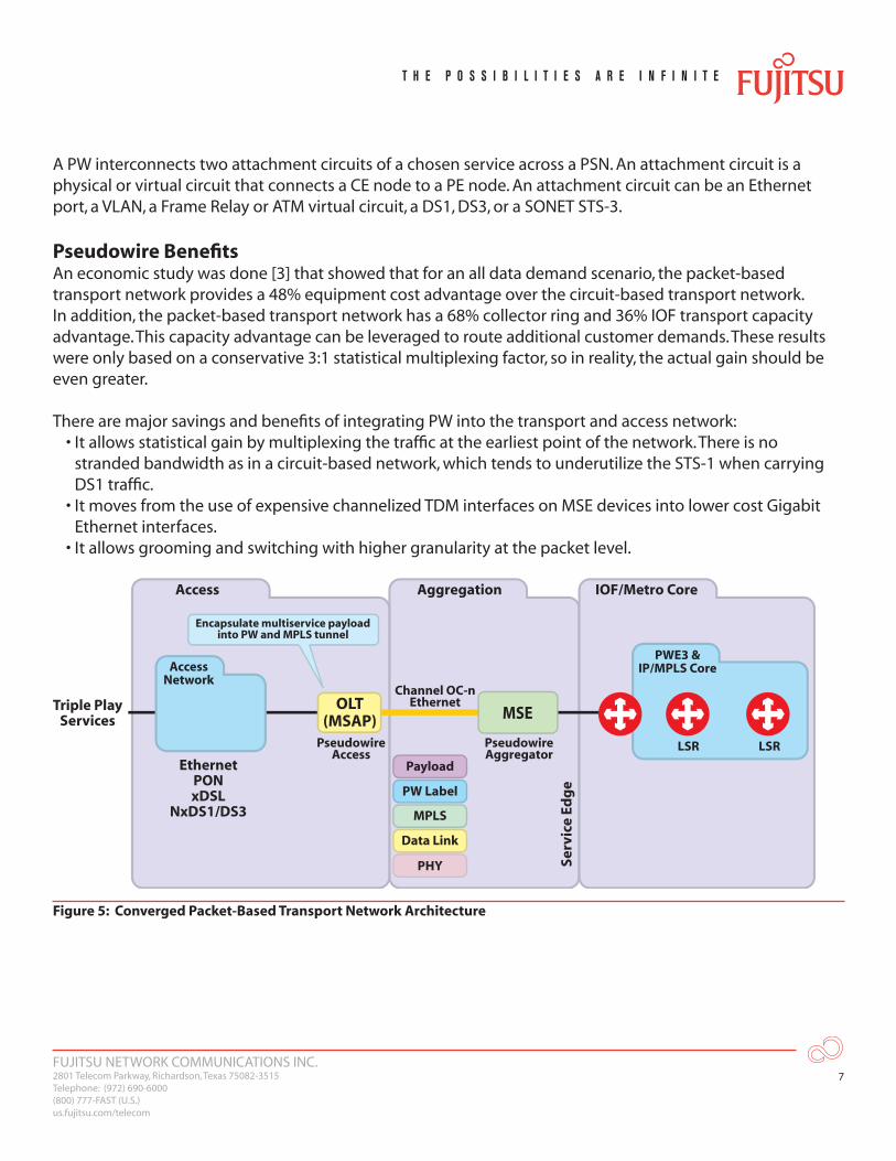
Pseudowire BenefitsAn economic study was done [3] that showed that for an all data demand scenario, the packet-based transport network provides a 48% equipment cost advantage over the circuit-based transport network. In addition, the packet-based transport network has a 68% collector ring and 36% IOF transport capacity advantage. This capacity advantage can be leveraged to route additional customer demands. These results were only based on a conservative 3:1 statistical multiplexing factor, so in reality, the actual gain should be even greater.
There are major savings and benefits of integrating PW into the transport and access network:• It allows statistical gain by multiplexing the traffic at the earliest point of the network. There is no
stranded bandwidth as in a circuit-based network, which tends to underutilize the STS-1 when carrying DS1 traffic.
• It moves from the use of expensive channelized TDM interfaces on MSE devices into lower cost Gigabit Ethernet interfaces.
• It allows grooming and switching with higher granularity at the packet level.
Access Aggregation IOF/Metro Core
Triple PlayServices
EthernetPONxDSL
NxDS1/DS3
Serv
ice
Edg
e
OLT(MSAP) MSE
PseudowireAggregator
Channel OC-nEthernet
LSR LSRPseudowireAccess
AccessNetwork
PWE3 &IP/MPLS Core
Encapsulate multiservice payloadinto PW and MPLS tunnel
Payload
PW Label
MPLS
Data Link
PHY
Figure 5: Converged Packet-Based Transport Network Architecture

FUJITSU NETWORK COMMUNICATIONS INC.2801 Telecom Parkway, Richardson, Texas 75082-3515Telephone: (972) 690-6000(800) 777-FAST (U.S.)us.fujitsu.com/telecom
8
Challenges Ahead for a Converged Packet-Based NetworkThe next-generation, converged packet-based transport market is still in its infancy. Management of the network will be a key issue. Service providers are comfortable with the current mode of operations, and any change will require new training and education.
Proper traffic management for multiple service classes in a large packet-based network will be challenging. Investing in too much silicon will increase the cost, but not investing enough will not be sufficient to provide QoS assurance to support SLAs.
ConclusionGPON is seen as the choice of the future to deliver high-bandwidth and multiple broadband services in the access network. GPON is also seen as a means to a packet-based converged network under unified network management. The IEEE VLAN tagging and bridging model is used initially to provide aggregation and switching services to residential and business customers. However, there is a limitation on protection, fault tolerance and scalability when the bridged Ethernet model is used. As the core network migrates to an MPLS-based network, it makes more sense to extend MPLS and PW support to the edge of the network, and eventually to the end point of the network.
The vision of network convergence is driven by packet-based services and the need for CAPEX and OPEX savings. The evolution of technology and applications is beginning to erase the barriers between different networks. Service providers can regain customers by bundling voice, data, and video services together. The need for a low cost, operationally efficient, and service performance guaranteed network creates a lot of challenges for service providers and equipment vendors. The next-generation, packet-based transport market is still in its early stages. However, the increased penetration of new packet-based broadband wireline technologies such as GPON can help to push the reality of network convergence even closer.
References[1] Sunan Han, William Yue, Stephen Smith, FTTx and xDSL: A Business Case Study of GPON versus Copper for
Broadband Access Networks, submitted to FTTH Conference paper to be published in October, 2006[2] William Yue, The Role of Emerging Broadband Technologies on the Converged Packet-Based Network,
Proceedings of OFC/NFOEC, Anaheim CA, March 2006[3] Sunan Han, Don O’Connor, William Yue, Next-Generation Packet-Based Transport Networks Economic Study,
Proceedings of OFC/NFOEC, Anaheim CA, March 2006
FUJITSU NETWORK COMMUNICATIONS INC.2801 Telecom Parkway, Richardson, Texas 75082-3515Telephone: (972) 690-6000(800) 777-FAST (U.S.)us.fujitsu.com/telecom
9
Acronym Descriptor
ANSI American National Standards Institute
APON ATM PON
ATM Asynchronous Transfer Mode
BONT Business Optical Network Termination
BPON Broadband PON
CAPEX Capital Expenditures
CE Customer Edge
CES Circuit Emulation Service
CLASS Custom Local Area Signaling Services
CO Central Office
E-LAN Ethernet Local Area Network
E-LINE Ethernet Private Line
EPON Ethernet PON
FSAN Full Service Access Network
FTTP Fiber to the Premises
Gbps Gigabits per Second
GEM Generic Encapsulation Method
GPON Gigabit Passive Optical Network
HDTV High-Definition Television
ID Identifier
IEEE Institute of Electrical and Electronic Engineers
IETF Internet Engineering Task Force
IGMP Internet Group Management Protocol
IOF Interoffice Facility
IP Internet Protocol
IPTV Internet Protocol Television
ITU-T International Telecommunication Union, Telecommunications Standards Section
km Kilometer
Acronym Descriptor
MAC Medium Access Control
Mbps Million Bits per Second
MDU Multiple Dwelling Unit
MPLS Multiprotocol Label Switching
MSE Multiservice Edge
MSO Multiservice Operator
OLT Optical Line Termination
ONT Optical Network Termination
OPEX Operating Expense
PE Provider Edge
PON Passive Optical Networking
POTS Plain Old Telephone Service
PSN Packet Switched Network
PW Pseudowire
PWE3 Pseudowire Emulation Edge-to-Edge
QoS Fiber to the Premises
RF Radio Frequency
SBU Small Business Unit
SDP Session Description Protocol
SFONT Single Family Optical Network Termination
SIP Session Initiation Protocol
SLA Service Level Agreement
SONET Synchronous Optical Network
STP Spanning Tree Protocol
TDM Time Division Multiplexing
VLAN Virtual LAN
VoIP Voice Over IP
WDM Wavelength Division Multiplexing
© Copyright 2007 Fujitsu Network Communications Inc.FUJITSU (and design)® and THE POSSIBILITIES ARE INFINITE™ are trademarks of Fujitsu Limited. All Rights Reserved. All other trademarks are the property of their respective owners.