how an induction motor works by equations (and physics) · the three-phase induction motor is the...
TRANSCRIPT
How an Induction Motor Works by Equations (and Physics)
Introduction: Induction motors are the commonest type of motor and account for a very large proportion of
heavy duty motors. Sizes vary from fractional horsepower to several thousand horsepower used for such appli-
cations as diesel-electric locomotives. Until relatively recently most such motors had to operate at fixed speeds
determined by the available line power frequency. Now the availability of power semiconductors and circuits
makes it possible to vary their speed and even in some cases hold them stationary.
All motors require two sets of magnetic fields, one of which might be supplied by a permanent magnet, that in-
teract to drive the rotor. One field acts as a sort of environmental field and the second, a time varying field, re-
acts with the first to drive the rotor. In induction motors the ‘environmental’ field is supplied by one or more
coils in the stator that create a rotating B field in the air gap between rotor and stator.
The distinguishing feature of induction motors is that their rotors have no permanent magnets or any need for
current to be driven into the rotor windings from any direct connection. (A direct connection would require
brushes, a commutator and more power supply connections, raising cost and decreasing reliability. This is why
induction motors are more popular.) Instead the rotor is wound with shorted turns in which the environmental
field induces a current. That current in turn produces a field that interacts with the environment to drive the
rotor.
The three-phase induction motor is the easiest motor of this type to understand so these notes start with that
type. The single-phase induction motor is more subtle and less efficient. It is discussed later.
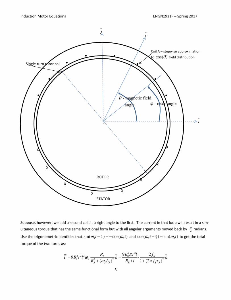
The magnetic field in the air gap from the voltage applied to the stator: The stator has three sets of windings
that are aligned at 120 degrees to each other and are driven by balanced currents that are 120 degrees out of
phase. Call the coils A, B, C and we will work in cylindrical coordinates. (See figure below.) The coils are wound
in such a way as to generate a field that is a rough stepwise approximation to a cos( )θ distribution. The wind-
ings overlap and each winding slot has two windings in it usually from different phases. (See 4 and 6 pole distri-
butions on the handout from class.) Here I assume a two pole distribution because it makes the explanation eas-
ier. Such a motor runs at the nominal speed range of 3500 – 3580 RPM. (Four and six pole motors run at 1720 to
1790 and 1140 to 1190 RPM respectively.)
[ ]10 0 2
cos( ) cos( ) cos( ) cos( )A
B B t r B t t rθ ω θ ω θ ω= = + + −���
ɵ ɵ
2 2 410 03 3 2 3
cos( )cos( ) [cos( ) cos( )]B
B B t r B t t rπ π πθ ω θ ω θ ω= − − = + − + −���
ɵ ɵ
4 4 210 03 3 2 3
cos( )cos( ) [cos( ) cos( )]C
B B t r B t t rπ π πθ ω θ ω θ ω= − − = + − + −���
ɵ ɵ
4 2102 3 3[3cos( ) cos( ) cos( ) cos( )]
A B CB B B B B t t t t rπ πθ ω θ ω θ ω θ ω= + + = − + + + + − + + −�� ��� ��� ���
ɵ
302
cos( )B B t rθ ω= −��
ɵ
Induction Motor Equations ENGN1931F – Spring 2017
2
Let and L R S
ω ω ω be the angular velocities of the magnetic field (line frequency), rotor, and slip respectively.
For convenience we assume that 0ϕ = at t = 0, which implies Rtϕ ω= and
S L Rω ω ω= − .
The flux in the single-turn coil on the rotor surface is
2 2
2 2
3 30 0 02 2
cos( ) cos( ) 3 cos( )ROTOR PEAK L S
B rl d B rl t d B rl t
π π
π π
ϕ ϕ
ϕ ϕ
θ ϕ ϕ ω ϕ ϕ ω
+ +
− −
′ ′ ′ ′Φ = − = − =∫ ∫
The voltage in the loop is 03 sin( )ROTOR S S
dV B rl t
dtω ω
Φ= − =
The current in the loop is:
00 2 2 2 2
3 sin( ) sin( ) cos( )3
( ) ( )
ROTOR S S R S S R SR S
LOOP R R R S R R S R
V B rl t R t L ti B rl
Z R jX R L R L
ω ω ω ω ωω
ω ω
= = = −
+ + +
For use later in calculating the heat wasted in the rotor, we will need the mean square value of this current or:
( )
2 2 2 22 01
2 22
9S
R
R S R
B r li
R L
ω
ω=
+
The B field at the leading edge of the rotor coil is:
3 30 02 2 2 2
( ( )) cos( ) sin( )PEAK L S
B B t r B t rπ πθ θ ϕ ω ϕ ω= − + = − − =���������������������
ɵ ɵ
Also at the leading edge of the rotor coil, the positive sign on the voltage implies that the current is out of the
page along the kɵ axis and therefore the force on the wire from the Lorenz force law is in the k r θ× = +ɵ ɵ ɵ direc-
tion. The rotor is being pushed in the direction of the rotation of the stator magnetic field. The total torque
from both sides of the loop is then
22 2 2
0 2 2 2 2
sin ( ) cos( )sin( )9
( ) ( )
R S S R S SS
R S R R S R
R t L t tT B r l k
R L R L
ω ω ω ωω
ω ω
= −
+ +
��ɵ
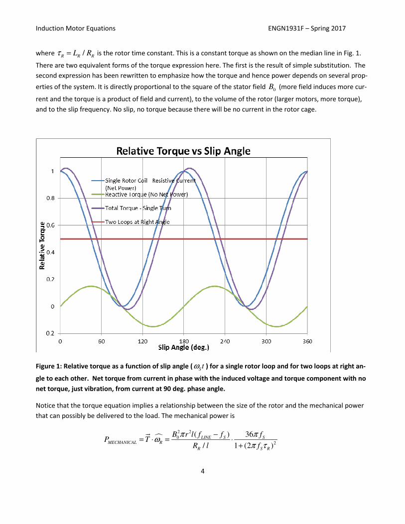
The first term in [ ]2 12
sin ( ) 1 cos(2 )S St tω ω= − gives a net positive average torque but it has 100 % variation in
magnitude from no torque to twice the average torque at twice the slip frequency. The second term has no net
average torque but would also represent vibration at twice the slip frequency. Figure 1 is a graph showing the
two terms and their sum. (The slip frequency is very low, typically 20 – 90 RPM or 0.33 to 1.5 Hz, so this would
be really bad vibration.)
Induction Motor Equations ENGN1931F – Spring 2017
3
Suppose, however, we add a second coil at a right angle to the first. The current in that loop will result in a sim-
ultaneous torque that has the same functional form but with all angular arguments moved back by 2π radians.
Use the trigonometric identities that 2
sin( ) cos( )S St tπω ω− = − and
2cos( ) sin( )
S St tπω ω− = to get the total
torque of the two turns as:
2 22 2 2 00 2 2 2
9 29
( ) / 1 (2 )
SRS
R S R R S R
B r l fRT B r l k k
R L R l f
πω
ω π τ= = ⋅
+ +
��ɵ ɵ
iɵ
X
•
•
•
• •
•
XX
STATOR
X
X
- rotor angleϕ
XX
ROTOR
•
- magnetic field
angle
θ
rɵjɵ
•
•
Single turn rotor coil
X
X
Coil A – stepwise approximation
to cos( )θ field distribution
Induction Motor Equations ENGN1931F – Spring 2017
4
where /R R R
L Rτ = is the rotor time constant. This is a constant torque as shown on the median line in Fig. 1.
There are two equivalent forms of the torque expression here. The first is the result of simple substitution. The
second expression has been rewritten to emphasize how the torque and hence power depends on several prop-
erties of the system. It is directly proportional to the square of the stator field 0B (more field induces more cur-
rent and the torque is a product of field and current), to the volume of the rotor (larger motors, more torque),
and to the slip frequency. No slip, no torque because there will be no current in the rotor cage.
Figure 1: Relative torque as a function of slip angle (Stω ) for a single rotor loop and for two loops at right an-
gle to each other. Net torque from current in phase with the induced voltage and torque component with no
net torque, just vibration, from current at 90 deg. phase angle.
Notice that the torque equation implies a relationship between the size of the rotor and the mechanical power
that can possibly be delivered to the load. The mechanical power is
�2 2
0
2
( ) 36
/ 1 (2 )
LINE S SMECHANICAL R
R S R
B r l f f fP T
R l f
π πω
π τ
−= ⋅ = ⋅
+
��
Induction Motor Equations ENGN1931F – Spring 2017
5
For low slip frequencies, the power of the motor is simply proportional to the product of the square of the gap
field strength with the volume of the rotor and the no-load speed of rotation. To increase motor power, general-
ly you have to increase the rotor volume or the speed of rotation since the B field strength is limited by the
properties of magnet iron and the effective resistance of the rotor is limited by the need to cool the rotor.
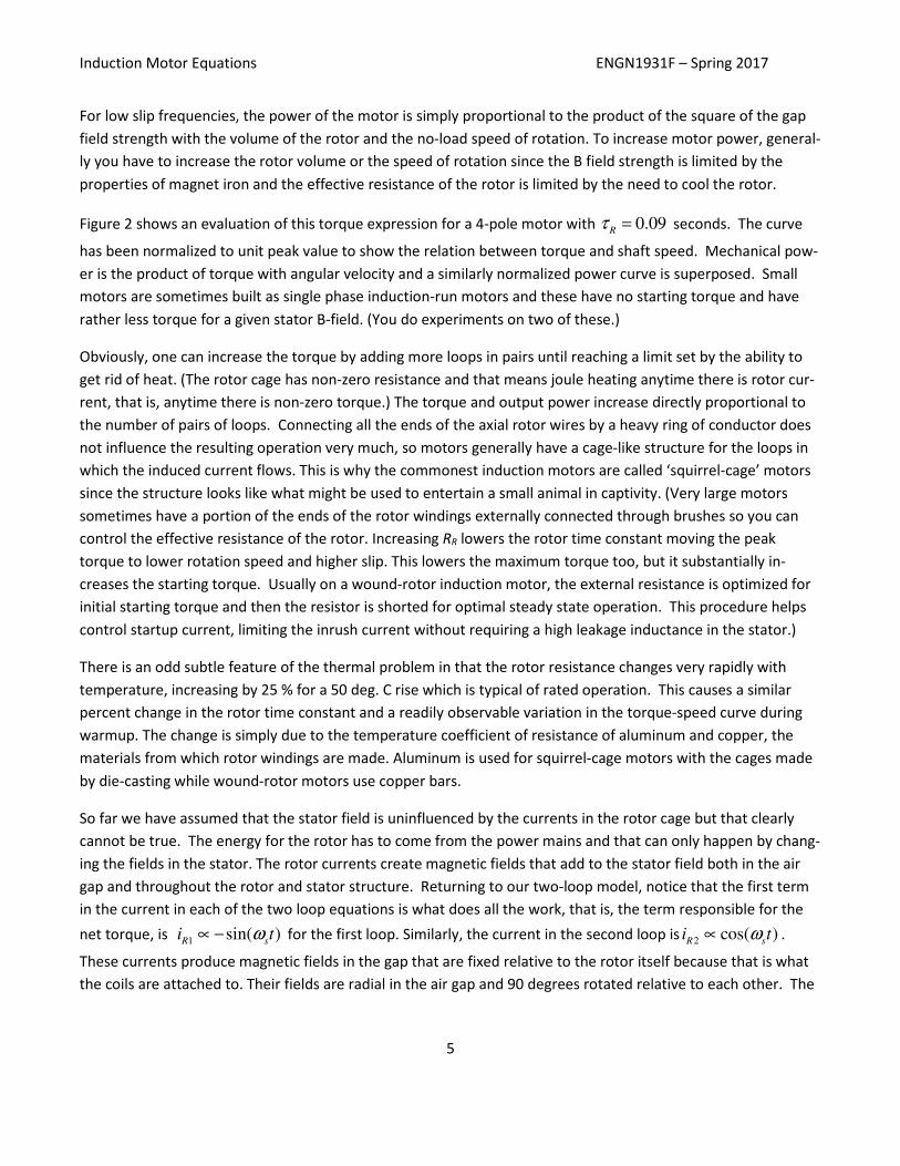
Figure 2 shows an evaluation of this torque expression for a 4-pole motor with 0.09R
τ = seconds. The curve
has been normalized to unit peak value to show the relation between torque and shaft speed. Mechanical pow-
er is the product of torque with angular velocity and a similarly normalized power curve is superposed. Small
motors are sometimes built as single phase induction-run motors and these have no starting torque and have
rather less torque for a given stator B-field. (You do experiments on two of these.)
Obviously, one can increase the torque by adding more loops in pairs until reaching a limit set by the ability to
get rid of heat. (The rotor cage has non-zero resistance and that means joule heating anytime there is rotor cur-
rent, that is, anytime there is non-zero torque.) The torque and output power increase directly proportional to
the number of pairs of loops. Connecting all the ends of the axial rotor wires by a heavy ring of conductor does
not influence the resulting operation very much, so motors generally have a cage-like structure for the loops in
which the induced current flows. This is why the commonest induction motors are called ‘squirrel-cage’ motors
since the structure looks like what might be used to entertain a small animal in captivity. (Very large motors
sometimes have a portion of the ends of the rotor windings externally connected through brushes so you can
control the effective resistance of the rotor. Increasing RR lowers the rotor time constant moving the peak
torque to lower rotation speed and higher slip. This lowers the maximum torque too, but it substantially in-
creases the starting torque. Usually on a wound-rotor induction motor, the external resistance is optimized for
initial starting torque and then the resistor is shorted for optimal steady state operation. This procedure helps
control startup current, limiting the inrush current without requiring a high leakage inductance in the stator.)
There is an odd subtle feature of the thermal problem in that the rotor resistance changes very rapidly with
temperature, increasing by 25 % for a 50 deg. C rise which is typical of rated operation. This causes a similar
percent change in the rotor time constant and a readily observable variation in the torque-speed curve during
warmup. The change is simply due to the temperature coefficient of resistance of aluminum and copper, the
materials from which rotor windings are made. Aluminum is used for squirrel-cage motors with the cages made
by die-casting while wound-rotor motors use copper bars.
So far we have assumed that the stator field is uninfluenced by the currents in the rotor cage but that clearly
cannot be true. The energy for the rotor has to come from the power mains and that can only happen by chang-
ing the fields in the stator. The rotor currents create magnetic fields that add to the stator field both in the air
gap and throughout the rotor and stator structure. Returning to our two-loop model, notice that the first term
in the current in each of the two loop equations is what does all the work, that is, the term responsible for the
net torque, is 1 sin( )R s
i tω∝ − for the first loop. Similarly, the current in the second loop is 2 cos( )R s
i tω∝ .
These currents produce magnetic fields in the gap that are fixed relative to the rotor itself because that is what
the coils are attached to. Their fields are radial in the air gap and 90 degrees rotated relative to each other. The
Induction Motor Equations ENGN1931F – Spring 2017
6
sine and cosine dependence on time means that the sum expresses a radial vector field that rotates relative to
the rotor at the slip frequency in the same direction as the rotor is moving.
Figure 2: Relative torque versus speed of rotation for a 4-pole 3-phase induction motor having a rotor time
constant of 0.09 sec. Power is the product of torque and speed of rotation so vanishes at locked rotor. Single
phase, induction-run motors make less efficient use of the stator B-field so have less torque for the same exci-
tation MMF.
One implication of this is that the rotor field seen by the stator is at the line frequency and has some fixed rela-
tion to the rotating B field the stator produces. By Lenz’s law this rotor field will be opposite to the stator field,
tending to reduce the net field in the stator.
Induction Motor Equations ENGN1931F – Spring 2017
7
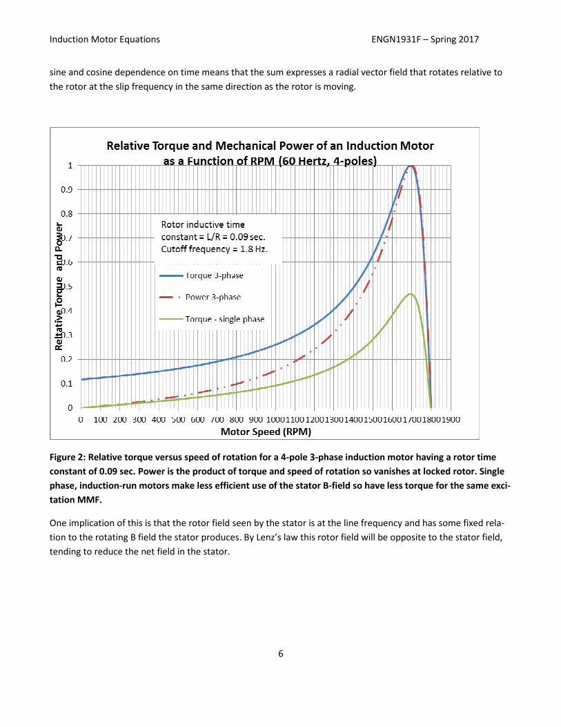
Figure 3: Circumferential B-field about the rotor from the slip frequency currents induced in a pair of current
loops around the rotor. The results do not depend on whether the loops are inset into rotor slots or not. The
direction of rotation of the fields is increasing angle about the rotor or CCW.
The shape of the rotor field is not altogether obvious. Consider a snapshot of the field around the rotor from
the current in one of our two loops. The field at that instant is uniform, that is, constant with angle, on each
side of the loop, whether or not the loop is inset into a slot in the rotor. If the current in the rotor were constant,
the voltage it would induce in a stator coil would be a square wave. With two rotor loops there are two overlap-
ping rectangular field shapes that are weighted by the time functions sin( )stω− and cos( )
stω , Figure 3 below
shows a series of snapshots of the field going counterclockwise around the rotor from one side of one coil at
several successive times corresponding to changes in the slip angle Stω . The fields are still constant for appre-
ciable segments of the rotor and do not resemble sinusoids. However, what should be clear is that the entire
pattern changes continuously in a way that shows CCW rotation (increasing angle about the rotor) at the slip
frequency.
If another pair of coils is added at right angles to each other and at 45 degrees to the first pair, then snapshots of
the field pattern look like Figures 4 and 5. Adding the second pair of rotor loops makes a field pattern that is a
stepwise approximation to a triangle wave. As more pairs are added, the approximation gets better and better.
Induction Motor Equations ENGN1931F – Spring 2017
8
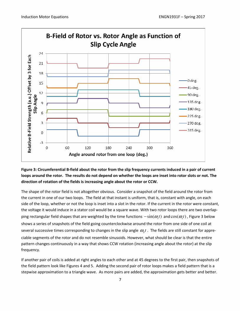
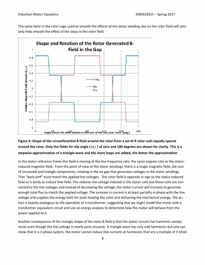
The same twist in the rotor cage used to smooth the effects of the stator winding slot on the rotor field will simi-
larly help smooth the effect of the steps in the rotor field.
Figure 4: Shape of the circumferential B-field around the rotor from a set of 4 rotor coils equally spaced
around the rotor. Only the fields for slip angle (Stω ) of zero and 180 degrees are shown for clarity. This is a
stepwise approximation of a triangle wave and the more loops are added, the better the approximation.
In the stator reference frame this field is moving at the line frequency rate, the same angular rate as the stator-
induced magnetic field. From the point of view of the stator windings, there is a single magnetic field, the sum
of sinusoidal and triangle components, rotating in the air gap that generates voltages in the stator windings.
That “back-emf” must match the applied line voltages. The rotor field is opposite in sign to the stator-induced
field so it tends to reduce that field. This reduces the voltage induced in the stator coils but those coils are con-
nected to the line voltages and instead of decreasing the voltage, the stator current will increase to generate
enough total flux to match the applied voltage. The increase in current is at least partially in phase with the line
voltage and supplies the energy both for joule heating the rotor and delivering the mechanical energy. The ac-
tion is exactly analogous to the operation of a transformer, suggesting that we might model the motor with a
transformer equivalent circuit and use an energy analysis to determine how the motor will behave from the
power applied to it.
Another consequence of the triangle shape of the rotor B-field is that the stator current has harmonic compo-
nents even though the line voltage is nearly pure sinusoid. A triangle wave has only odd harmonics but one can
show that in a 3-phase system, the motor cannot induce line currents at harmonics that are a multiple of 3 times
Induction Motor Equations ENGN1931F – Spring 2017
9
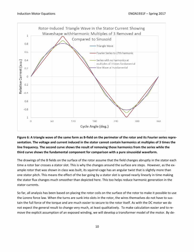
the line frequency. (This is the same reason that generators are wye-wound but connect to the primary of delta-
wound distribution transformers. Wye-wound motors never have their common point connected to the com-
mon point of their source supply.) Figure 6 shows a triangle wave overlaid by its Fourier series representation
with components out to 27 times the fundamental frequency. One cannot see the difference. However, if the
3, 6, 9,… harmonics are removed, a bent sinusoid with only about 6 % total harmonic distortion is formed. The
figure compares the triangle voltage to both the waveshape of its induced currents and a pure sinusoid at the
fundamental.
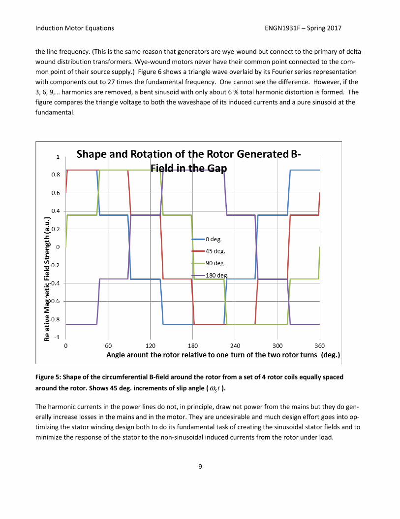
Figure 5: Shape of the circumferential B-field around the rotor from a set of 4 rotor coils equally spaced
around the rotor. Shows 45 deg. increments of slip angle (Stω ).
The harmonic currents in the power lines do not, in principle, draw net power from the mains but they do gen-
erally increase losses in the mains and in the motor. They are undesirable and much design effort goes into op-
timizing the stator winding design both to do its fundamental task of creating the sinusoidal stator fields and to
minimize the response of the stator to the non-sinusoidal induced currents from the rotor under load.
Induction Motor Equations ENGN1931F – Spring 2017
10
Figure 6: A triangle wave of the same form as B-field on the perimeter of the rotor and its Fourier series repre-
sentation. The voltage and current induced in the stator cannot contain harmonics at multiples of 3 times the
line frequency. The second curve shows the result of removing those harmonics from the series while the
third curve shows the fundamental component for comparison with a pure sinusoidal waveform.
The drawings of the B fields on the surface of the rotor assume that the field changes abruptly in the stator each
time a rotor bar crosses a stator slot. This is why the changes around the surface are steps. However, as the ex-
ample rotor that was shown in class was built, its squirrel-cage has an angular twist that is slightly more than
one stator pitch. This means the effect of the bar going by a stator slot is spread nearly linearly in time making
the stator flux changes much smoother than depicted here. This too helps reduce harmonic generation in the
stator currents.
So far, all analysis has been based on placing the rotor coils on the surface of the rotor to make it possible to use
the Lorenz force law. When the turns are sunk into slots in the rotor, the wires themselves do not have to sus-
tain the full force of the torque and are much easier to secure to the rotor itself. As with the DC motor we do
not expect the general result to change very much, at least qualitatively. To make calculation easier and to re-
move the explicit assumption of an exposed winding, we will develop a transformer model of the motor. By de-
Induction Motor Equations ENGN1931F – Spring 2017
11
riving the model parameters experimentally, we can simulate the line current, torque and efficiency as functions
of slip frequency and load by energy arguments.
A formal approach to solving for the steady state currents and power in a motor begins with the observations
that:
• At rest a motor with two rotor turns is a transformer with 5 coils, two of them shorted.
• The self-inductances of the windings are independent of the rotor position
• The mutual inductances of stator to rotor windings are proportional to the sine or cosine of the rotor
angle relative to the magnetic axes of the stator coils.
• All stator windings have one resistance and all rotor windings a different resistance that is the same
for all rotor loops.
• Flux induced in a coil is M PRM
L iΦ = and therefore the induced voltage is ( )M PRM
dv L i
dt= where
PRMi
is the current in the inducing coil. (Note: the usual formula for the voltages in a transformer or even
for a single coil follows from this if the inductance is independent from time, but that is not the case
for a motor.)
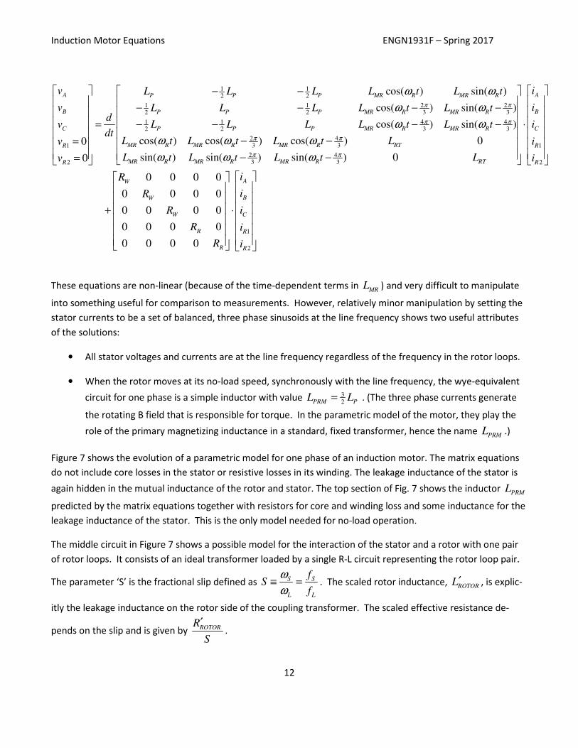
With these observations, the steady state equations for a motor with two rotor turns can be written in matrix
form. In discussing generator design, we found that for sinusoidally wound stator coils, the mutual inductance
between those coils was 12M P
L L= − where the inductance of one stator coil is P
L . The inductance, RT
L , is
the total inductance of a rotor winding including both what is fully coupled to the stator and what is rotor leak-
age current. This is greater than the R
L inductance in the equations for motor power and torque. The latter is
actually a leakage inductance and will be part of a parametric model. R
L appears here through the relationship
between P
L , RT
L andMR
L based on what fraction of the stator flux is captured by the rotor. With these re-
sults, the motor terminal equations become:
Induction Motor Equations ENGN1931F – Spring 2017
12
1 12 2
2 21 12 2 3 3
4 41 12 2 3 3
2 43 31
2
cos( ) sin( )
cos( ) sin( )
cos( ) sin( )
cos( ) cos( ) cos( ) 00
0
A P P P MR R MR R
B P P P MR R MR R
P P P MR R MR RC
MR R MR R MR R RTR
R
v L L L L t L t
v L L L L t L td
L L L L t L tvdt
L t L t L t Lv
Lv
π π
π π
π π
ω ω
ω ω
ω ω
ω ω ω
− −
− − − − − − − −=
− −= =
1
2 43 3 2
1
2
sin( ) sin( ) sin( ) 0
0 0 0 0
0 0 0 0
0 0 0 0
0 0 0 0
0 0 0 0
A
B
C
R
MR R MR R MR R RT R
AW
BW
CW
R R
R R
i
i
i
i
t L t L t L i
iR
iR
iR
R i
R i
π πω ω ω
⋅ − −
+ ⋅
These equations are non-linear (because of the time-dependent terms in MR
L ) and very difficult to manipulate
into something useful for comparison to measurements. However, relatively minor manipulation by setting the
stator currents to be a set of balanced, three phase sinusoids at the line frequency shows two useful attributes
of the solutions:
• All stator voltages and currents are at the line frequency regardless of the frequency in the rotor loops.
• When the rotor moves at its no-load speed, synchronously with the line frequency, the wye-equivalent
circuit for one phase is a simple inductor with value 32PRM P
L L= . (The three phase currents generate
the rotating B field that is responsible for torque. In the parametric model of the motor, they play the
role of the primary magnetizing inductance in a standard, fixed transformer, hence the name PRM
L .)
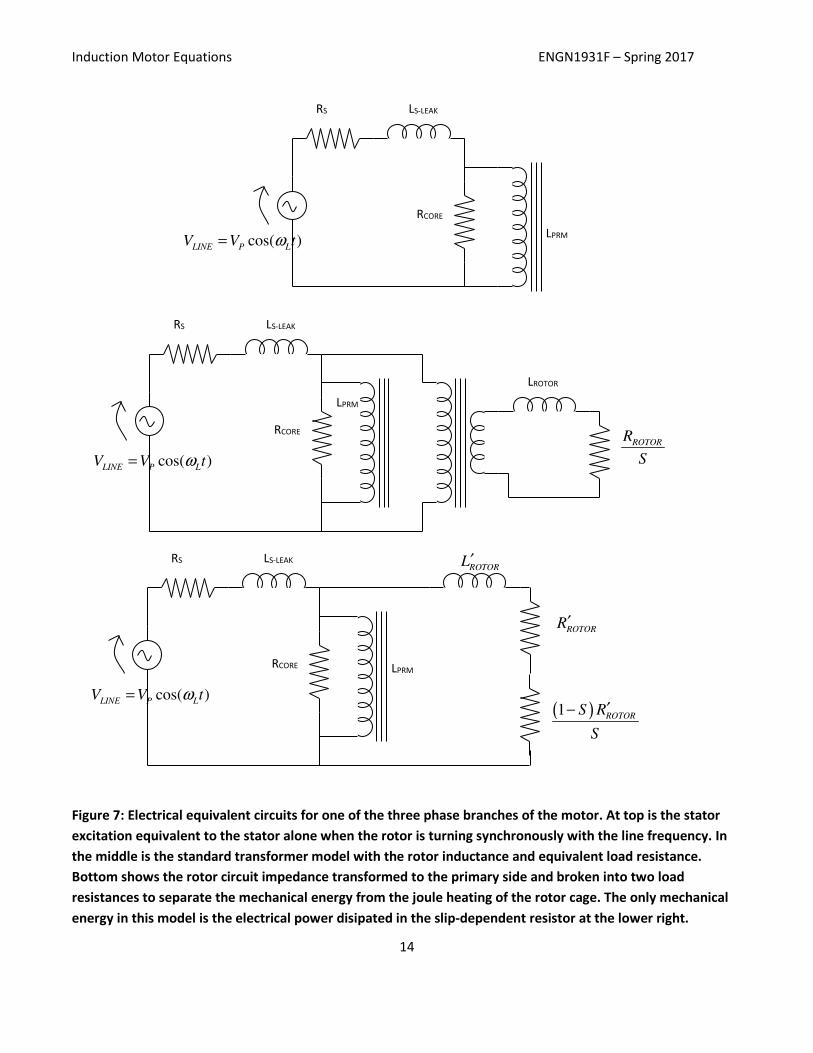
Figure 7 shows the evolution of a parametric model for one phase of an induction motor. The matrix equations
do not include core losses in the stator or resistive losses in its winding. The leakage inductance of the stator is
again hidden in the mutual inductance of the rotor and stator. The top section of Fig. 7 shows the inductor PRM
L
predicted by the matrix equations together with resistors for core and winding loss and some inductance for the
leakage inductance of the stator. This is the only model needed for no-load operation.
The middle circuit in Figure 7 shows a possible model for the interaction of the stator and a rotor with one pair
of rotor loops. It consists of an ideal transformer loaded by a single R-L circuit representing the rotor loop pair.
The parameter ‘S’ is the fractional slip defined as S S
L L
fS
f
ω
ω≡ = . The scaled rotor inductance,
ROTORL′ , is explic-
itly the leakage inductance on the rotor side of the coupling transformer. The scaled effective resistance de-
pends on the slip and is given by ROTORR
S
′.
Induction Motor Equations ENGN1931F – Spring 2017
13
As additional loop pairs are added to a rotor, the power and torque from each pair add directly so the electrical
power both real and reactive in the rotor must increase linearly with the number of such pairs. With a fixed volt-
age, the line voltage across PRM
L , dividing RROTOR and LROTOR by N increases the total power by a factor of N.
Thus, if this is an adequate model of a motor with two rotor loops, then it can be trivially extended to any num-
ber of loop pairs by dividing by the number of loop pairs. It is not necessary to do this division explicitly because
the final model will not include this factor but its parameters will be chosen to match the performance of the
fully assembled motor.
The bottom circuit in Figure 7 shows removing the ideal transformer by scaling the R-L load appropriately. There
is no way to measure the turns ratio externally so there is little benefit in keeping the ideal transformer in the
model. For this final version of a full parametric model to be satisfactory, it must be possible to select its pa-
rameters to predict the power delivered to the rotor for both heat and mechanical energy at all values of slip.
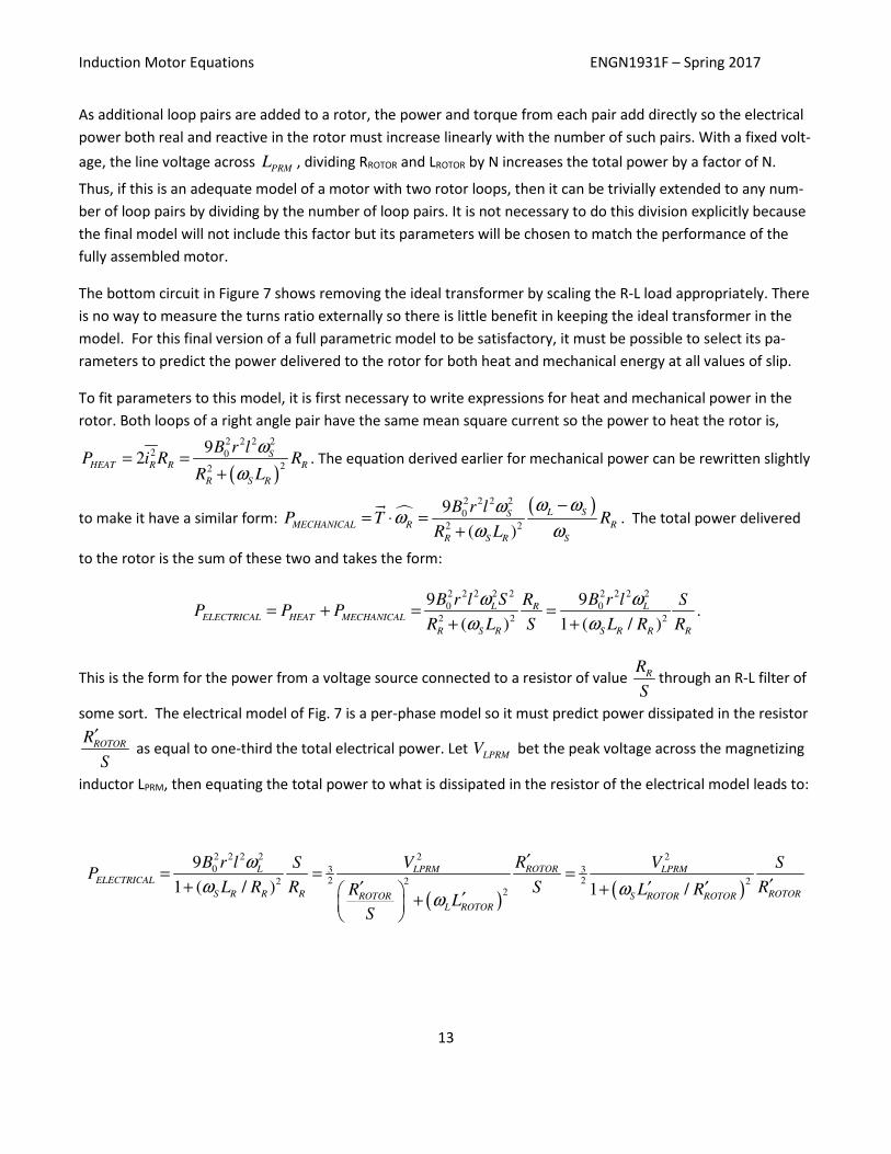
To fit parameters to this model, it is first necessary to write expressions for heat and mechanical power in the
rotor. Both loops of a right angle pair have the same mean square current so the power to heat the rotor is,
( )
2 2 2 22 0
22
92 S
HEAT R R R
R S R
B r lP i R R
R L
ω
ω= =
+. The equation derived earlier for mechanical power can be rewritten slightly
to make it have a similar form: � ( )2 2 2 2
0
2 2
9
( )
L SSMECHANICAL R R
R S R S
B r lP T R
R L
ω ωωω
ω ω
−= ⋅ =
+
��. The total power delivered
to the rotor is the sum of these two and takes the form:
2 2 2 2 2 2 2 2 2
0 0
2 2 2
9 9
( ) 1 ( / )
L LRELECTRICAL HEAT MECHANICAL
R S R S R R R
B r l S B r lR SP P P
R L S L R R
ω ω
ω ω= + = =
+ +.
This is the form for the power from a voltage source connected to a resistor of value RR
Sthrough an R-L filter of
some sort. The electrical model of Fig. 7 is a per-phase model so it must predict power dissipated in the resistor
ROTORR
S
′ as equal to one-third the total electrical power. Let
LPRMV bet the peak voltage across the magnetizing
inductor LPRM, then equating the total power to what is dissipated in the resistor of the electrical model leads to:
( ) ( )
2 2 2 2 2 2
0 3 32 22 22
2
9
1 ( / ) 1 /
L ROTORLPRM LPRMELECTRICAL
S R R R ROTORS ROTOR ROTORROTORL ROTOR
B r l RV VS SP
L R R S RL RRL
S
ω
ω ωω
′= = =
′+ ′ ′′ + ′+
Induction Motor Equations ENGN1931F – Spring 2017
14
Figure 7: Electrical equivalent circuits for one of the three phase branches of the motor. At top is the stator
excitation equivalent to the stator alone when the rotor is turning synchronously with the line frequency. In
the middle is the standard transformer model with the rotor inductance and equivalent load resistance.
Bottom shows the rotor circuit impedance transformed to the primary side and broken into two load
resistances to separate the mechanical energy from the joule heating of the rotor cage. The only mechanical
energy in this model is the electrical power disipated in the slip-dependent resistor at the lower right.
cos( )LINE P L
V V tω=
RS LS-LEAK
RCORE
LPRM
cos( )LINE P L
V V tω=
RS LS-LEAK
RCORE
LPRM
ROTORR
S
LROTOR
cos( )LINE P L
V V tω=
RS LS-LEAK
RCORE LPRM
( )1ROTOR
S R
S
′−
ROTORL′
ROTORR′
Induction Motor Equations ENGN1931F – Spring 2017
15
This result shows that the electrical model has the correct dependence of both mechanical and heating power
on slip frequency when the time constant is chosen properly. The division of power into its thermal and mechan-
ical components is emphasized in Fig. 7 by dividing the equivalent rotor resistance into two parts. Similarly anal-
ysis of the stator coil structure shows that the proportionality of 0LPRM LV B rlω∝ is also correct. Finally choose
the parameter ROTOR
R′ to scale the power for the particular motor.
An empirical fit of parameters is straightforward and is similar to the transformer extraction problem in your lab.
The stator resistance can be measured at DC. The core resistance and LPRM are derived from extrapolating the
line current at low slip to the no-load, synchronous values. The rotor parameters may be found from low-voltage
locked rotor conditions and be checked by curve fitting the slip versus torque and power curves. As the model
for a single phase motor is similar to this one, parameters for that problem are derived similarly.
The Single-phase Induction Motor: Small motors from 1/5 to 2 H.P. are often single phase, having the ad-
vantage of being usable where three phase power is not available. Three phase motors are from 85 % to 97 %
efficient but single phase motors are generally less efficient because they make poorer use of their “environ-
mental” B field. The split-phase motor of your first motor lab is an example of this problem. It is so inefficient
that the sale of newly manufactured motors of this type is no longer permitted under Department of Energy
regulations.
The split-phase motor has a single stator coil that is wound sinusoidally in the same way as one of the stator
coils of the three phase motor. The B field induced by connecting this to the power mains is given by:
[ ]10 0 2
cos( ) cos( ) cos( ) cos( )B B t r B t t rθ ω θ ω θ ω= = + + −��
ɵ ɵ .
Notice that this is a stationary magnetic field but that it can be regarded as two, counter-rotating fields. A rotor
at rest in this field has slip equal to 1 in both directions. There is no applied torque because the two rotating
fields are equal strength pulling in opposite directions. In this condition, the rotor current is very high and the
rotor heats up rapidly.
However, should we find a way to set the rotor into motion even slowly in one direction, say counterclockwise,
the counterclockwise torque from the cos( )Rtθ ω− term increases because the slip is decreasing in that direc-
tion. Similarly the clockwise torque decrease as the clockwise slip is increasing. The difference is now sufficient
to accelerate the rotor in the CCW direction until the motor reaches peak torque. Further acceleration then de-
creases the torque until the motor reaches a balance between torque and load.
In order to be self-starting, single phase motors are equipped with a second set of stator coils.