house wiring 20090305
TRANSCRIPT

7/31/2019 House Wiring 20090305
http://slidepdf.com/reader/full/house-wiring-20090305 1/21
House Electrical Installations and EMFs Alasdair and Jean Philips
House Wiring and EMFs
Introduction
Electric and magnetic fields (EMFs) are produced as a result of the flow of electric current. The
wiring in our houses, the electric appliances and lights we use, all produce EMFs. EMFs can bemeasured using an appropriate meter (for details see end of this article add comment).
At mains-frequency, the magnetic fields and the electric fields need to be considered separately,and there are different safety guidelines for each. At high frequencies, such as those used fortelecommunications, magnetic and electric fields are so linked they are usually consideredtogether as “electromagnetic radiation”. ‘Frequency’ means the number of vibrations per second,so ‘high frequency’ means more vibrations per second.
In our homes we are surrounded by EMFs, both from the house wiring and from the applianceswhich use the electricity supply. This article is about fields from the house wiring. The three
illustrations below show examples of EMFs in the home from a lamp and a transformer. Theelectric and magnetic fields are similar to those produced by house wiring.
Switched off
This picture shows electric fields fromsockets and from the wire to the lamp,even though the light is not switched on.These electric fields are present all thetime electricity is present in the wires,even if it is not actually being used.
Switched on
This picture shows the electric andmagnetic fields from the lamp when it isswitched on. The electric fields nowextend to the lamp. Magnetic fields arealso being produced by the current
flowing along the wire and light bulb –although these usually reduce quicklyas you get further away.
At the socket
This illustration shows a common type of mains-adapter transformerthat converts the 230 volt mains electricity to a lower voltage needed formany, usually portable, electronic devices. Once again, both electric and
magnetic fields are emitted. The magnetic fields are considerable andcan still be high up to half a metre away from the transformer.
Page 1 of 21

7/31/2019 House Wiring 20090305
http://slidepdf.com/reader/full/house-wiring-20090305 2/21
House Electrical Installations and EMFs Alasdair and Jean Philips
Sometimes transformers are built into radios and music players and are actively emittingmagnetic fields all the time the player is plugged into the mains, even when it is not actually inuse.
A magnetic field is produced whenever an electrical current flows. The larger the current, thehigher the magnetic field produced. A mains electricity electrical circuit effectively starts and
ends at the local electricity substation transformer. The supply from the substation feeds thebuilding’s electricity meter, main switch, consumer unit (“fuse box”) and final circuits. If theoutward and return currents are be equal and flow in the same cable (wire bundle), as theyshould be, then the magnetic fields produced in the house rooms should be negligible.
What are normal EMFs?
The magnetic fields in the house, with the electricity switched off, should be as low as possibleand are usually less than the UK average of 0.04 microtelsa (μT). For detached houses set backfrom the road, the average fields from outside sources is about 0.02 μT. For flats and for terracedhouses right up to the pavement have higher fields, however if they are about about 0.1 μT thenan external electrical supply fault should be suspected.
External ‘faults’ are caused by many things, but the commonest are Neutral and Earth currentsflowing in the wrong conductors and in metal water and gas pipes. When all “go” and “return”currents travel together in the same cable, or bundle of cables, then magnetic fields fall off veryrapidly as you move away from the cables. If they don’t run together then much higher thanusual magnetic fields can extend over wide areas. There is little that you can do to reduce such
fields other than pester you local electricity distributor to investigate them and, hopefully, correct
Page 2 of 21

7/31/2019 House Wiring 20090305
http://slidepdf.com/reader/full/house-wiring-20090305 3/21
House Electrical Installations and EMFs Alasdair and Jean Philips
the worst faults. See “External Net Currents” later in this document for more technicalinformation about this.
In most cases, a cable supplying 230 volts single-phase power will have three conductors; phaseand neutral conductors providing the outward and return paths for the current and a safety(protective) earth conductor. The protective conductor usually carries virtually no current except
under fault conditions, although some small currents are to be expected from capacitive circuitdevices. The protective earth conductor is there to provide an alternative path back to the sourcefor the electricity if a fault to earth occurs. This conductor is usually an uninsulated wire innormal circuit cables but is fitted with green and yellow (or just green on older cables) plasticsleeving at its ends.
The Neutral conductor is connected to earth at the local electricity substation (and sometimeselsewhere, too, under “protective multiple earthing” [PME] schemes) and is used to carry thereturning current. This wire is now coloured blue in the UK (compulsory by April 2006 for newinstallations). It used to be black, which is the colour that will be still be found in most buildingwiring (installed in 2005 and earlier).
The third wire is the “Live”, “Line” or “Phase” conductor and this has the electric pressure (i.e.the voltage) on it and it is the source of the current used to power electrical equipment. This wirenow has brown insulation in the UK (compulsory since April 2006 for new installations). It usedto be red, which is the colour that will be still be found in most building wiring (installed in 2005and earlier).
The easiest way for an electrician to check the circuits for current flows is byusing a clamp-ammeter around the cable. Although this is best done around thePhase/Line and Neutral conductors only, this is not always easy to do.However, in practice, a very good indication is usually obtained by using the
clamp-meter around the whole (twin & earth) cable. This is becausediscontinuities in Line or Neutral will still show up and also any leakage toearth rarely stays in that specific earth conductor. The clamp-meter readingshould rarely show more than 0.01 A (10 mA), even when the circuit is loadedusing a high load such as an electric kettle or a 3 kW fan heater. If it does, thenthere is a wiring fault which will be causing elevated magnetic fields.
Final “ring” circuits usually feed the socket-outlets in UK homes. These “rings” of cable alwaysgive rise to higher magnetic fields than simple “radial” or “tree and branch” wiring. A tree orradial circuit forces the return current to travel back down the same piece of cable. A “ring” finalcircuit is not required, but is recognised, in BS7671 (IEE/IET Wiring Regulations) and is what
most electricians traditionally install. They were originally introduced after the second WorldWar in order to minimise the use of copper wire while at the same time allowing for a number ofelectrical heaters, etc, to be used at the same time.
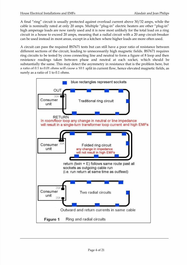
In a “ring” final circuit, the wires are laid out in a circle (more or less), starting and finishing atthe consumer unit (fuse box). This means that current used from a socket-outlet has two possibleways to flow to and from the consumer unit. Currents may not flow equally both ways aroundthe ring, so the magnetic fields produced may not cancel, and the cables then radiate these highermagnetic fields into the room and the adjacent rooms.
At every socket-outlet two cables are joined. A small difference in the impedance back each way
to the consumer unit around the loop will cause a problem almost as bad as a poor connection.
Page 3 of 21
7/31/2019 House Wiring 20090305
http://slidepdf.com/reader/full/house-wiring-20090305 4/21
House Electrical Installations and EMFs Alasdair and Jean Philips
A final “ring” circuit is usually protected against overload current above 30/32 amps, while thecable is nominally rated at only 20 amps. Multiple “plug-in” electric heaters are other “plug-in”high amperage loads are now rarely used and it is now most unlikely for the total load on a ringcircuit in a house to exceed 20 amps, meaning that a radial circuit with a 20 amp circuit-breakercan be used instead in most areas, except in a kitchen where higher loads are more often used.
A circuit can pass the required BS7671 tests but can still have a poor ratio of resistance betweendifferent sections of the circuit, leading to unnecessarily high magnetic fields. BS7671 requiresring circuits to be tested by cross connecting line and neutral to form a figure of 8 loop and thenresistance readings taken between phase and neutral at each socket, which should besubstantially the same. This may detect the asymmetry in resistance that is the problem here, buta ratio of 0.1 to 0.01 ohms will cause a 10:1 split in current flow, hence elevated magnetic fields, assurely as a ratio of 1 to 0.1 ohms.
Page 4 of 21

7/31/2019 House Wiring 20090305
http://slidepdf.com/reader/full/house-wiring-20090305 5/21
House Electrical Installations and EMFs Alasdair and Jean Philips
In the worst case, which is surprisingly common, a Line or Neutral actually gets disconnected(often as a result of incompetent DIY) and this effectively results in a single-turn transformerloop. When a significant load is applied, the magnetic field in rooms throughout the inside of thering can rise to many microtesla.
Comment:
For situation ‘B’ ~ this is with phase and neutral broken towards opposite ends of the ring. Foronly one broken ring conductor, the EMF levels will somewhere between the levels shown as A(perfect condition) and B.
Page 5 of 21

7/31/2019 House Wiring 20090305
http://slidepdf.com/reader/full/house-wiring-20090305 6/21
House Electrical Installations and EMFs Alasdair and Jean Philips
Choosing a consumer unit
The consumer unit is the "fuse box" which goes between theelectricity meter and all the electrical circuits in the house.Modern units do not contain fuses, but miniature
mechanical circuit breakers (MCBs) which have replacedthem. They often also contain an extra protective devicecalled a residual current device RCD, which replaces theisolator switch. Modern consumer units can also containother devices such as time switches and door-belltransformers.
The purpose of the MCB is to protect the wiring of its circuit from excessivecurrent due to an overload or short-circuit - in a similar but more controlled waythan a wire fuse did. If the rated current is exceeded, the MCB will trip, andmerely needs to be switched back on again to re-connect. It is more convenient
than a fuse, and it is more obvious to see which one has tripped after a faultoccurs. Common values are 6A for lighting circuits, 16A or 20A for radial powersocket circuits and immersion heaters, 32A for ring mains, 7kW electric showersand electric cookers, and 40A for 8kW showers and larger electric cookers.
RCDs (sometimes wrongly called Earth Leakage Circuit Breakers - see below)are primarily designed to protect against electrocution (death from electricshock) by detecting current flowing to earth. The RCD monitors the balance ofthe Neutral and Phase currents and disconnects the circuit if any out-of-balance current reaches a pre-set limit. Because under normal circumstancesthere should be very little earth current, they can be made very sensitive:
30 milliamps (0.03 A) is common, with 100 mA (0.1 A) for circuits with motorsand higher current switched loads.
In some cases, the RCD does not protect all the circuits, in which case there is also an overallisolator switch to disconnect everything. This type of arrangement is called a "split load"consumer unit. Under the latest (2008) 17th Edition UK Wiring Regulations (BS 7671) many morecircuits are required to be protected by a 30 mA RCD and some consumer boxes now have twosplit multi-MCB circuit groups each of which is protected by an RCD. It is normal to feed afreezer from an unprotected circuit so that in the event of a trip while the house is unoccupied, itwill continue to function. Garages and outhouses are also often fed in this way if they have theirown RCD, so that the main house RCD will not trip in the event of a fault.
This sensitivity also give the RCD the ability to detect other faults such as partial live-earthbreakdown, which can cause fires, and Neutral-Earth shorts which cause unwanted net currentswhich increase magnetic field levels. However, it cannot protect against the less common live-neutral electric shock and it does not protect against overloads so must always be used inconjunction with MCBs or fuses.
A small amount of earth leakage is to be expected in normal situations, such as from damp, fromfluorescent fittings and mains filters on appliances, and there are all sorts of nasty spikes whichcan occur on the mains supply and be interpreted as a fault. RCDs are therefore designed to offera compromise between the degree of protection offered and the risk of "nuisance tripping".
Page 6 of 21

7/31/2019 House Wiring 20090305
http://slidepdf.com/reader/full/house-wiring-20090305 7/21
House Electrical Installations and EMFs Alasdair and Jean Philips
An RCD usually protects several circuits, any one developing a fault willresult in them all being disconnected. It can be better to use an RCBO (acombined MCB and RCB) for each circuit, though these are significantlymore expensive and physically larger at the present time. Some advancedRCDs/RCBOs have extra features, such as detection of live/neutralreversal or earth disconnection (for which they need an earth sense wire).
RCDs are current operated, but there is also an older voltage operatedEarth Leakage Circuit Breaker (ELCB). There is some confusion overthese names. The voltage operated type has a solenoid connectedbetween the earth of the protected area (e.g. all the sockets and pipes inthe house) and "true" earth (the sheath of the incoming supply cable or anearth rod). When there is sufficient voltage across the solenoid from acurrent flow of a few tens of milliamps, the ELCB will trip, disconnectingthe circuits protected by it. It then has to be reset manually.
Voltage operated devices have the disadvantage that they can only detect leakage to the earth
circuit that passes through them. Thus, they will not detect current passing through the body tothe ground when using equipment outdoors, or to current passing through the body to plumbingif it is connected to the ground and therefore cannot be included in the protection circuit. Theyare now only used when the house is supplied by what is known as a “TT” system where aProtective Earth Conductor is not supplied by the electricity supply company and the house relieson a local Earth Electrode buried in the ground. These are not favoured nowadays (2008) in theUK. Even where TT systems are used, an RCD is generally now preferred to an ELCB.
In order to keep the electric fields in the house low, we strongly recommend a metal consumer
unit (the cheaper ones, often used, are plastic and provide no electric field shielding). We alsorecommend the used of screened wire for the same reason - see the section on “Minimising
Electric Fields”.
Page 7 of 21

7/31/2019 House Wiring 20090305
http://slidepdf.com/reader/full/house-wiring-20090305 8/21
House Electrical Installations and EMFs Alasdair and Jean Philips
Here is a more detailed diagram of a traditional UK final ring circuit:
An alternative for electrical designers and electricians that insist on a “traditional ring finalcircuits” is the “folded ring”. Two cables are taken together around the rooms, one connecting tothe socket outlets and the other connecting to the final socket outlet to complete the loop. Thisuses more cable but avoids the problems described above as the return current path is alwaysclose to the outward current path.
Page 8 of 21

7/31/2019 House Wiring 20090305
http://slidepdf.com/reader/full/house-wiring-20090305 9/21
House Electrical Installations and EMFs Alasdair and Jean Philips
Radial circuits have low emissions of magnetic fields. It is often possible to convert an existing“ring” final circuit into one long radial circuit without major rewiring by removing one endconnection and lowering the value of the protective device to 20 amps. In other cases it is possibleto break the “ring” near its middle and, likewise, protect the two new circuits with either one or
two 20 amp circuit-breakers depending on the expected electrical loading. 2 x 20A radial circuitsprovides for more load than the original ring final circuit.
If a Residual Current protective Device (RCD) is used, any significant imbalance in Line &Neutral currents (i.e. any Net currents, which will almost always raise magnetic field levels) willcause the circuit to trip out and indicate a fault. RCDs are usually double-pole devices that switchboth the “line” and “neutral” conductors. They can cause unnecessary circuit trips when somehigh loads are suddenly applied to the circuit, especially if these are highly inductive orcapacitive loads. An RCD can be combined with an over-current protective device (MCB) in oneunit and it is then known as an RCBO.
It is now a legal requirement that any (newly wired) sockets that might be connected to an
extension cable to be used outside (i.e. if they are close to a garden window) must be protected byand RCD or RCBO.
An earthed metal conduit system (with cables or insulated wires in metal pipes), with radial finalcircuits will always produce the lowest electric and magnetic fields. The earthed metal pipescompletely screen the electric field but, generally, have little effect on the magnetic field.
Page 9 of 21

7/31/2019 House Wiring 20090305
http://slidepdf.com/reader/full/house-wiring-20090305 10/21
House Electrical Installations and EMFs Alasdair and Jean Philips
Another common cause of high magnetic fields comes from poorly laid-out lighting wiring.When possible, Phase (Live) and Neutral conductors should always be run together, keeping the“go” and “return” currents together in the same cables. To minimise magnetic fields, both Liveand Neutral should be taken to each luminaire (light) and then the Live take to-and-from eachswitch as a twin and earth cable. The Live and Neutral conductors should always be connected tothe same circuit from the consumer box and should never be connected between different circuits.
It is not uncommon to find two-way switched lighting circuits that, incorrectly, interconnectdifferent circuits. This is against the requirements of BS7671. It is important that such circuits arefed from only one Live and are kept with their own Neutral; special 3 core + earth cable (easilyavailable) is required to do this satisfactorily.
Electric Fields
Electric fields are present all the time the home circuits are connected to the mains and not justwhen current flows. A common cause of elevated electric fields is from the wiring of lighting
circuits. It is not always obvious that these are the source, and care needs to be taken interpretingelectric field readings taken with hand-held meters.
To track down the source it is worth referencing the meter to a known good electrical earth - itcan then easily be used to pinpoint the live sources. Otherwise it is easy to become confused aselectric fields can travel through conducting bodies (including people) and then return to anearby earth - such as a radiator. It is not uncommon to obtain apparently high electric fieldreadings from a radiator, when the source of the field is actually below the floor and the radiatoris acting as the return Earth, with the circuit connection being supplied by the person holding themeter.
Electric fields are produced by a conductor having a potential (voltage) on it with respect to earth,and here an earthed metal conduit system effectively provides an electrical screen around all suchconductors. However, the electric field from a three-core (twin & earth) cable falls off fairlyrapidly and, by careful routing, fields in critical areas (such as beds) can be kept fairly low evenwith normal unscreened cable. They will always be higher than when screened (or metalconduited) wiring is used because, if not screened, some of the voltage always ‘leaks’ into thebuilding structure (usually capacitively coupled).
Ideally earthed metal conduit piping should be used to carry the cables as this will eliminate theelectric fields from the cables.
The metal mountings for halogen lights should be earthed - this will significantly reduce theelectric fields. Ideally, one side of the secondary of the low-voltage transformer should also beearthed, but this is not always possible with electronic low-voltage adapters that are oftensupplied nowadays.
Metal radiators are normally earthed through the legally required earth bonding to the metalwater pipes. If plastic pipes are used, it is still recommended that most metal radiators areearthed. This will require an earthing lead to the nearest mains electricity safety earthing point(usually at the nearest socket).
Mineral insulated cables (e.g. Pyrotenax) are screened by their metal outer covering, but areexpensive to install. “Armoured” (steel wire screened) cables also emit very little in the way ofelectric or magnetic fields.
Page 10 of 21

7/31/2019 House Wiring 20090305
http://slidepdf.com/reader/full/house-wiring-20090305 11/21
House Electrical Installations and EMFs Alasdair and Jean Philips
There are also screened low-halogen fire-retardant cables available (e.g. “fire-safe” TW950 andMulti-Plus, see below) – mainly intended for critical safety applications, but also suitable for
general wiring as they are available in standard conductor sizes. They are easy to terminate butdo have a larger bending radius requirement than ordinary PVC cable. It is recommended thatthey are protected by an RCD as it is not clear how much current the foil could carry withoutlocal overheating if the cable was mechanically damaged, shorting LIVE to screen.
NOTE: There is a specific British Standard screened cable intended for fixed wiring
installations. The standard is BS 8436:2004, Electric cables. 300/500 V screened electric cableshaving low emission of smoke and corrosive gases when affected by fire. Screened cable to BS8436:2004 is fully approved for domestic building installations. The soft skin fire cables described
below are not intended for this application, although they are satisfactory and may be used toreduce electric fields. The other cables, described below, are approved to installations in the UK,but not specifically for residential installations. They are quite adequate (and maybe better forscreening) but a “Part-P” electrical inspector may query their use. They are legal and suitable!
Most "FP200" type cables use a solid aluminium or copper screening sheath, however some FP-200 cables use a (permitted) polyester screening/fire-protection tape that is not very electricallyconductive and will not provide good electric field screening.
Advice given to Powerwatch by UK cable approvals organisation BASEC is that the correctscreened cable to use is BS 8436 but that is expensive and difficult to get in short lengths.
Prysmian FP200 Gold (to BS 7629-1) (see below) is a good cable to use.
Page 11 of 21

7/31/2019 House Wiring 20090305
http://slidepdf.com/reader/full/house-wiring-20090305 12/21
House Electrical Installations and EMFs Alasdair and Jean Philips
The wires in the cores are identical for BS 7629-1 and BS 8436. The BS 8436 cable has the wiresloose inside a strong circular aluminium circular screen which then has a PVC sheath bonded onto it.
The 7629-1 cable has the screening foil tightly wound around the inner wires and then the outersheath is extruded over the top leaving virtually no internal air spaces at all.
"By choice" you should use the white sheathed cable to distinguish it from red alarm cables, but ifyou used the red cables for general purposes that should be clearly stated next to everyconsumer/distribution box/panel.
‘Prysmian FP200 Gold’ FIRE RESISTANT CABLE
The cable has a low smoke sheathing. It is subject to a special nail penetration test. The purposeof the metal foil tape in the fire performance cables is to retain the cores together during a fire,when the external sheathing has burned away. Although it does act as a electrical screen its mainpurpose is to trigger an RCD in the event of a nail penetration.
Please note that FP200 Gold is a Prysmian registered trade mark product, which complies withBS7629. It should not be used as a generic term for other manufacturer's products, especially asthicknesses and materials are frequently different and may have different characteristics. FP200Gold has an aluminium tape laminated to the LSOH sheath. FP200 Gold is fully compliant withBS7629-1 and is BASEC and LPCB approved.
The Prysmian FP200 Gold (formerly Pirelli FP200) is approved for fire detection and fire alarmcritical signal paths in BS5839-1:2002 'standard' application areas, voice alarm systems to BS5839-8:1998 (and 2006) and emergency lighting systems to BS5266-1:2005. In addition to approvals to
BS7629-1 and BS6387 Category CWZ FP200 Gold has received BASEC and LPCB approval toBS5839-1:2002 for 'standard' applications. If you require a cable to purely reduce the electric field,and this cable is installed such that it is not required to meet clause 522.6.6, then Prysmian FP200Gold can be used in such an application.
Guide trade prices (Autumn 2008) are:
About £45 for 100m of BS 6004 - standard 2.5 mm2 two core PVC flat twin and earth.
About £100 for 100m of BS 7629-1 cable - two core 2.5 mm2 - fire performance cable - FP200 Gold
About £150 for 100m of BS 8436 - screened cable “for general building installations” as above.
Although the screened cables are considerably dearer, the actual cost of the cable is only arelatively small part of the re-wire costs. Labour is usually the largest element.
Page 12 of 21

7/31/2019 House Wiring 20090305
http://slidepdf.com/reader/full/house-wiring-20090305 13/21
House Electrical Installations and EMFs Alasdair and Jean Philips
FIRE-SAFE TW950 FIRE RESISTANT CABLE
This cable has been designed to meet the latest standardsfor fire protection and alarm systems in BS5839 pt1, andfor use in emergency lighting BS5266 pt1, and ismanufactured and tested to BS7629: 1993. Applications:Public Buildings, Schools, Hospitals etc. Fire-Safe TW950 issuitable for use in applications where zero halogen lowsmoke cables are required to maintain circuit integrityduring fire.
• Conductors: Plain annealed copper to BS6360 (1.5mm solid, 2.5mm 7 strands).
• Core Insulation: Silicon rubber to BS7655 and wrapped in glass tape.
• Earth Conductor: Tinned annealed copper to BS6360.
• Electrostatic Screen: Thermoplastic zero halogen low smoke compound.
• Colour: White Clip Needed: C478 Gland Needed: G2528
PYROTENAX Multi-Plus fire resistant cable
Multi-Plus is a multi-purpose screened and fire-proof wiring cable system from Tyco.
MultiPlus is a new generation of high performance cableswhich has been specifically developed to meet the everchanging needs of the modern building services
installation. MultiPlus is a multi-purpose, simple to install,one step cable system. This will effectively reduce electricfields to zero.
http://www.tycothermal.com
Page 13 of 21

7/31/2019 House Wiring 20090305
http://slidepdf.com/reader/full/house-wiring-20090305 14/21
House Electrical Installations and EMFs Alasdair and Jean Philips
There is also suitable, reasonably priced, screened flexible cable now available (types CY and SY),intended for eliminating electrical interference in industrial and commercial use, which can beused instead of conduited cables provided the screens are carefully and effectively terminated.The braided screen is electrically separate from the insulated green/yellow earth conductor and
they need to be connected at every junction point.
This can be used for rewiring anexisting non-conduited house whenelectric fields are to be minimised,though we would recommend that
fire-resistant cables were used as a first choice. This is because they are easier to terminate and areand fully approved way of installing mains wiring within buildings.
Demand Switches
“Demand switches” can be used to minimise electric fields from circuits which are not actuallysupplying power. A Demand Switch is an electronically controlled mechanical circuit breaker(MCB) that replaces the 230 volts AC with a low or a DC voltage that is then used to sense when aswitch is closed, when the 230 volts AC is automatically re-connected to the circuit. These can befitted in consumer units and wired in series with the circuit over-current device (circuit-breakeror fuse).
They are not needed if metal conduited or screened cables are used in the installation, but can beuseful for remedial electric field reduction.
EMFields stock the most commonly used and generally useful one from Gigahertz Solutions
range. It can switch 16 amps and be used for lights (one or two circuits protected at 6A or 10Aand 6A) or radial power circuits (with a 16A MCB in series, one Demand Switch for each circuit)
Page 14 of 21

7/31/2019 House Wiring 20090305
http://slidepdf.com/reader/full/house-wiring-20090305 15/21
House Electrical Installations and EMFs Alasdair and Jean Philips
but not for UK ring final circuits. We do not know of a 30A one suitable for ring final circuits, butwe would anyway always recommend splitting every ring final circuit into two radial circuits.They will each need to be protected with 16A MCBs.
To reduce electric fields in the home, it really is a much better long-term solution to rewire usingscreened cable. However, there are times where this is just too much work and expense and
fitting a few demand switches is an easier and cost-effective solution.
It is usually necessary to install another consumer unit next to the existing one to take thedemand switches. It is often easiest to have all the Demand Switches in the new consumer unitand keep the MCBs and RCDs in the existing one. The demand switches are fitted after the MCBsbefore the cables go off to the lights or to the power sockets. Demand switches do not offeroverload protection.
External ‘faults’ in the supply that can cause high magnetic fields
The Neutral conductor is connected to Earth at the local electricity substations and, withProtective Multiple Earthing (PME), at regular intervals along the low-voltage electricitydistribution system in the locality. This can give rise elevated magnetic field levels, but it isdifficult to get the electricity company to do anything about it as the levels are below the ICNIRPguidance of 100 μT and the electricity supply still seems to work correctly for users.
Generally, if an Earth facility is provided by the local electricity distribution network operator(DNO), the consumer’s Earthing conductor is either connected to the neutral or the cable sheath/armour. Neutral and Earth must not be connected together anywhere else in the building.
An undetected Neutral to Earth short–circuit can cause a high magnetic field within a building.Insulation tests on the Live and Neutral conductors of each circuit will detect such a fault.Insulation tests must officially be performed when any wiring changes are made (though theyoften aren’t as it is extra hassle for the electrician) and, ideally, at suitable periodic intervals whenthe building wiring is checked. A Neutral to Earth short-circuit contravenes the requirements ofthe IEE Wiring Regulations.
One problem that causes high magnetic fields due to external distribution problems, but one thatcan be dealt with by the building owner, are “stray” net currents flowing on incoming metal gasand water pipes. These “stray” currents enter, or leave, the building and then transfer via therequired electrical safety bonding to the electrical safety earth. The currents are easily detected byeither holding a magnetic field meter next to the pipes where they enter the building (the fieldswill rise as you get closer to the pipe) or by using a clamp-ammeter around the pipe. Zero currentshould be flowing in the pipe. If there is more than about 10 or 20 mA (and it can be as high asseveral amps), then a short section of suitable plastic pipe should be inserted into the metal pipe.This will break the circuit and stop the current flowing.
NOTE ! : Internal metal pipework must still be correctly Earth-bonded as per BS7671. Also, theincoming pipe should be isolated as near the ground as possible and any exposed pipe coveredwith insulating tape or sleeving as, under fault conditions, it would be possible for a significantvoltage to exist between the house Electrical Safety Earth and the incoming pipe tail that couldgive rise to a voltage shock hazard.
Page 15 of 21

7/31/2019 House Wiring 20090305
http://slidepdf.com/reader/full/house-wiring-20090305 16/21
House Electrical Installations and EMFs Alasdair and Jean Philips
IMPORTANT NOTES:
Remember that electricity can be lethal, and all wiring installations should be checked by acompetent person with suitable test equipment to ensure that they are safe and that they fullycomply with the UK BS7671 Requirements for Electrical Installations.
The Building Regulations (Part P) set out the latest applicable requirements. It is not worthtaking any risks with electrical safety in the course of trying to reduce EMFs – in the UK, about 20people are killed by accidental electrocution each year.
We are aware that many trades people are set in their normal ways of doing things. Some of thetechniques described in this article will be different from what they are used to doing.
We believe that the techniques and materials described in this leaflet will provide installationsthat comply with the latest thinking and requirements of BS7671.
If any electrician or electrical contractor disputes this then we would like to hear from them.Please email details to [email protected] or [email protected].
It is now illegal for unqualified people to undertake major electrical work without formalindependent third-party inspection and test.
EMFields PRO meters that measure both electric and magnetic fields can be hired or bought fromEMFields www.emfields.org/equipment/pro.asp 3030B
This leaflet has been written in 2007 and revised in March 2009by Alasdair Philips, BSc(Eng), DAgE, MIAgE, MInstPhys, for Powerwatch and EMFIELDS.
Page 16 of 21
7/31/2019 House Wiring 20090305
http://slidepdf.com/reader/full/house-wiring-20090305 17/21
House Electrical Installations and EMFs Alasdair and Jean Philips
Wiring in homes - extract from SAGE Report
This is extracted from the First Report (July 2007) of the UKDepartment of Health’s SAGE working group on ELF EMFs.
3.1 Introduction
In all homes, the internal wiring makes some contribution to the electric and magnetic fields inside thehome. For magnetic fields, however, normal, correctly installed home wiring is rarely a significant sourceof fields, because “go” and “return” currents are usually balanced and close together, resulting in a largedegree of cancellation. Home wiring becomes a significant source of magnetic fields only if one of anumber of specific features is present (described in more detail in Supporting Paper S9):
• A ring-main power circuit where, because of an interrupted conductor or a high-impedance joint, thephase and neutral currents split in different proportions round the two arms of the ring, resulting inunbalanced currents.
• A circuit, usually a two-way switched lighting circuit, where the phase and neutral currents flowdifferent ways round a loop
• An accidental connection between neutral and earth within the wiring which allows some of theneutral current to return via earth and creates an unbalanced current
• Loops of current in the vicinity of the electricity meter and the consumer unit
• The electricity meter itself; traditional rotating disc meters produce relatively high magnetic fields,which fall off over a metre or so but which can be a significant source of exposure eg if a child sleepswith their head close to the meter, including on the other side of a wall.
The best data available in the UK1 suggest that, of the 0.4% of homes (80,000 homes) where fields aregreater than 0.4 µT, perhaps a quarter or 0.1% (20,000 homes) are due to house wiring.
For electric fields, external sources of field are less significant inside the home because they are screened bythe building structure. Wiring in the home is therefore a more significant source of field than for magneticfields. In addition, the cancellation between phase and neutral is not as effective. Electric fields areproduced by all wiring containing a live conductor, unless the wiring is contained in a metal conduit or hasa screen in the sheath, and are present all the time.
For blocks of flats and apartments, we believe our analysis and conclusions about internal wiring stillapply. In addition, however, fields can arise from the way electricity is distributed to the flats within abuilding. These issues will be considered by the next SAGE Working Group, on Distribution, discussed inSection 1.3.
3.2 Options for reducing fields from wiring in the homeWe looked at a long list of possible options for reducing exposures, so as to be sure of covering everythingrelevant, including:
Primarily to reduce magnetic fields
• Changing ring power circuits to radial circuits
• Inserting plastic sections in metal services such as gas and water pipes
• Keep “go” and “return” currents together at all times
• Protect whole installation with a residual current device (RCD, see Supporting Paper S9)
1 http://www.hpa.org.uk/radiation/publications/hpa_rpd_reports/2005/hpa_rpd_005.htm
Page 17 of 21

7/31/2019 House Wiring 20090305
http://slidepdf.com/reader/full/house-wiring-20090305 18/21
House Electrical Installations and EMFs Alasdair and Jean Philips
Primarily to reduce electric fields
• Placing all wiring in metal conduits
• Use all-metal accessories and mounting boxes
• Use cables with a screen
• String-pull or remote control light switches
• Locate sockets away from the bed
• Apply earthed metal screening tape over cables in walls and ceilings
• Use demand switches to disconnect voltage when circuit not in use
For both electric and magnetic fields
• Site the meter and consumer unit appropriately
• Use extra-low-voltage circuits in homes
• Use DC circuits in homes
To allow people to know about and reduce their exposures by their own actions
• Labelling of meter and installed equipment
• Requiring a document in each home recording the fields
We assessed these options against the following criteria:
• Safety
• Effectiveness at reducing fields
• Level of technical difficulty
• Complexity to introduce
• Cost
3.3 Best available options
For wiring in homes, there is no single “best” option, and instead we have identified the following as bestavailable package of options:
To reduce magnetic fields:
• Wire power circuits as radial circuits instead of ring circuits
• Ensure that “go” and “return” currents are kept physically close together at all time, particularly inrelation to two-way switching of lights and to the layout of underfloor heating cables
• Protect the whole electrical installation with a residual current device (RCD)
• Use electronic electricity meters rather than rotating-disc meters• Keep meter tails physically close together
• Position consumer units (and rotating-disc meters) away from high-occupancy areas
To reduce electric fields:
• Wire homes using cable which has a screen within the overall sheath
We have examined these options for their consequences, including safety. None have any seriousproblems, and specifically, we do not believe that any are less safe than at present, and some bring safetyadvantages.
These options could be applied to varying degrees, which we summarise in Table 3.1.
Page 18 of 21

7/31/2019 House Wiring 20090305
http://slidepdf.com/reader/full/house-wiring-20090305 19/21
House Electrical Installations and EMFs Alasdair and Jean Philips
Precautionary Action Implementation Characteristics
Do nothing; no change
to existing situation
No legislation, regulation
or voluntary codesneeded
No cost
Likely continuing dispute Potential political fallout and continuing
criticism
No reduction in exposure levels
Provide information No legislation orregulation needed
Demonstrates acceptance of desirability ofreducing exposures
Empowers people to make a choice
Could either allay or aggravate publicconcern
Low cost
Does nothing directly to reduce exposures
Voluntary testing ofhomes for high fields.Remedial action paidfor by householder.
No legislation orregulation needed.Agreed procedures andtraining for tests.
Empowers people to make a choice
Take up may be low (based on radonexperience)
New wiring practicesfor all new homes
IET guidance toelectricians
Reduces exposures in new homes andwhen homes rewired
Additional cost
Changes to Wiring
Regulations or BuildingRegulations
Mandatory testing ofexisting homes andremediation
Building Regulations orother regulation orsecondary legislation
More effective at reducing high fields now
Considerable extra cost
Training for electricians
(shaded areas show SAGE’s preferred options)
3.4 ConclusionsAs discussed in Section 2.1, our primary focus is to reduce magnetic fields, because it is these which aremost strongly associated with childhood leukaemia. For electric fields, we consider more research wouldbe desirable. To apply our package of options to reduce magnetic fields to a new home or when completelyrewiring an existing home would, we estimate, cost an additional £20. The benefit in terms of reducedcases of childhood leukaemia (“WHO/HPA”), even assuming that magnetic fields are causal, we estimateas £1 per new home (the details of how we derived these figures are in Supporting Paper S10). Consideringother adverse health effects as well as childhood leukaemia (“California”, as discussed in Section 1.1)would strengthen the case for these options, but amongst the stakeholders within SAGE we do not haveagreement on whether this is appropriate. Therefore, we do not have a clear justification for this package ofoptions in health cost-benefit terms. However, in view of the small absolute cost per home, particularly
when seen in the context of the total cost of building a new home, and the fact that there is a trend for some
Page 19 of 21

7/31/2019 House Wiring 20090305
http://slidepdf.com/reader/full/house-wiring-20090305 20/21
House Electrical Installations and EMFs Alasdair and Jean Philips
of these options to happen anyway for other reasons, we nonetheless recommend that this package ofoptions should be implemented.
Therefore we recommend that:
• The IET should issue guidance to electricians (contained either in the On Site Guide or as aseparate Guidance Note) recommending the change to radial power circuits, keeping “go”and “return” currents together, and keeping meter tails together. The IET Wiring Regulations Policy Committee should consider this, and the Government representatives onthis committee should take responsibility for monitoring acceptance and implementation ofthis recommendation. We considered the alternative of recommending a change to BS7671(the “wiring regulations”), but felt that guidance to electricians would be just as effectiveand easier to achieve.
• BS7671 should be changed to require RCDs for the whole installation. We understand thisis likely to happen with the next revision in January 2008 anyway, but if it does not, then theIET should implement it as guidance for electricians as for the previous options.
• Use of rotating-disc electricity meters should be phased out. There is already a strong trendto this and 95% of meters currently being installed in new properties, and to meet re-certification requirement, are electronic. However, it is not clear how this can be mademandatory.
• Alternatively, depending on how effectively a move to electronic meters can occur, CLG(formerly ODPM) should modify the Building Regulations to specify that electricity metersand consumer units for new homes should not be located close to high-occupancy areas.
• HPA should produce information for householders on sources of field and steps that can betaken to reduce them.
These measures would result in the package of options being applied to new homes and when rewiring istaking place anyway. We do not believe it is justifiable to require these options to be appliedretrospectively in all homes. However, if a test shows that high-magnetic fields are present in a home dueto some feature of the wiring, we believe it is sensible to take actions to reduce the field, using whichever ofthese options is appropriate to the source of field that has been identified. Taking such action would alsobe justified in cost-benefit terms as shown in Supporting Paper S10.
We therefore recommend:
• That where high magnetic fields as a result of house wiring are identified in an existing home,the source of those fields should be removed or remediated.
• To identify high fields in existing homes, it should be an option that a simple measurement ofmagnetic fields be performed when either a Periodic Inspection of the house wiring or aBuilding Survey in connection with the sale of the home is being performed.
This would require at least some electricians and surveyors to be suitably trained and equipped. If this test
identified high fields, identification of the source might require a separate visit by a more highly trainedperson. We describe the tests we envisage in Supporting Paper S11. In due course, in the light of
Page 20 of 21

7/31/2019 House Wiring 20090305
http://slidepdf.com/reader/full/house-wiring-20090305 21/21
House Electrical Installations and EMFs Alasdair and Jean Philips
experience, a separate decision could be made as to whether to make this test mandatory, perhaps as partof the home buyer’s report.
Occasionally, high fields in one home arise from a source in the neighbouring home. We recognise that theoptions available to the person affected may be limited in this situation.
In line with Supporting Paper S3, we consider that the measures we propose for homes should also beapplied to schools, similarly applying to new wiring and available as an option for existing wiring, thoughwe recognise this places an extra burden on school budgets.
For electric fields, there is a less strong case for reduction, and we do not recommend that our optionshould be implemented routinely. Rather, it should be available to those householders ordevelopers who wish to use it.
Our option for reducing electric fields requires a type of cable (conventional twin-and-earth but with ascreen inside the sheath) that is available at present only at a considerably higher price than normal cable;we recommend that a cheaper version should be developed. In the interim, we give other methods ofreducing electric fields which householders or developers can use if they wish, in Supporting Paper S12.
The above section (3) is extracted from the First Report (July 2007) of theUK Department of Health’s SAGE working group on ELF EMFs.
The Stakeholder Advisory Group on ELF EMFs (SAGE) was set up by the Department of Healthto explore the implications and to make practical recommendations for a precautionary approachto power frequency electric and magnetic fields. It has now produced its first report, and moreinformation is available from the Department of Health website.
http://www.dh.gov.uk/en/Publichealth/Healthprotection/DH_4089500
The main first report and the supporting papers are worth downloading and reading. Somespecifically relate to house wiring.
his was followed by a "Cross-Party Inquiry into Childhood Leukaemia and Extremely LowFrequency Electric and Magnetic Fields (ELF EMF)", which was set up to allow the five Membersto consider in detail the evidence for an association between Electric and Magnetic Fields (EMF)from High Voltage Overhead Transmission Lines (HVOTL) and an increased risk of childhoodleukaemia and determine what should be done. Their findings and recommendations can befound on the ePolitix.com website.
http://www.epolitix.com/EN/Forums/CPIELFEMF