host lh750
TRANSCRIPT

COULTER® LH 750 WORKSTATION
Host Transmission Specification
� � � � � � � � � � � � � � � �� � �
GEN•S
PN 4277303B (April 2002)
COULTER CORPORATIONA Beckman Coulter CompanyMiami, Florida 33196-2500 USA

LEGAL NOTICES
READ ALL PRODUCT MANUALS AND CONSULT WITH BECKMAN COULTER-TRAINED PERSONNELBEFORE ATTEMPTING TO OPERATE INSTRUMENT.
HAZARDS AND OPERATIONAL PRECAUTIONS AND LIMITATIONS
WARNINGS, CAUTIONS, and IMPORTANTS alert you as follows:
WARNING - Might cause injury.CAUTION - Might cause damage to the instrument.IMPORTANT - Might cause misleading results.
CAUTION System integrity might be compromised and operational failures might occur if:
r This equipment is used in a manner other than specified. Operate the instrument as instructed in the Product Manuals.
r You introduce software that is not authorized by Beckman Coulter into your computer. Only operate your system’s computer with software authorized by Beckman Coulter.
r You install software that is not an original copyrighted version. Only use software that is an original copyrighted version to prevent virus contamination.
Beckman Coulter, Inc. urges its customers to comply with all national health and safety standards such as the use of barrier protection. This may include, but it is not limited to, protective eyewear, gloves, and suitable laboratory attire when operating or maintaining this or any other automated laboratory analyzer.
WARNING Risk of operator injury if all covers are not secured in place prior to instrument operation or you attempt to replace a part without carefully reading the replacement instructions. Do not attempt to replace any component until you carefully read the instructions for replacing the component.
IMPORTANT If you purchased this product from anyone other than Beckman Coulter or an authorized Beckman Coulter distributor, and, if it is not presently under a Beckman Coulter service maintenance agreement, Beckman Coulter cannot guarantee that the product is fitted with the most current mandatory engineering revisions or that you will receive the most current information bulletins concerning the product. If you purchased this product from a third party and would like further information concerning this topic, call your Beckman Coulter Representative.

REVISION STATUS
Initial Issue, 7/01Software Version 1A.
Revision B, 4/02Software Version 2A. Derived from internal Part Number 0302000G.Updated Section 4.3, Dilution Factor field comments.Removed all references to “+ Subset” globally.Added WBC Threshold Full Histogram Group Fields.Added new Section 3.18, Collate the ToDo List.Updated General Information Group Fields from 29 groups to 24 groups.Added notes to Tables 4-3 and 4-15, respectively.Updated the following tables: 4-1; 4-3; 4-6; 4-8; 4-12; 4-13; 4-21; 4-30; 4-31; 4-33; 4-39; 4-41; 4-46; 4-48; 4-52; 5-1; 5-2; 5-4.Removed NRBC note from Tables 4-24 and 4-46.Added “Note: Parameter selection does not affect control transmissions.” to Tables 4-43; 4-44; 4-46; 4-48; and 4-50.Updated Control Information Group 34, removed reference WBC Count Field.Updated Section 6.2, added SOH to table.Updated Section 8.1.
iiiPN 4277303B
This document applies to the latest software listed and higher versions. When a subsequent software version changes the information in this document, a new issue will be released.

REVISION STATUS
PN 4277303B iv

CONTENTS
LEGAL NOTICES, ii
REVISION STATUS, iii
1 INTRODUCTION, 1-1
1.1 PURPOSE, 1-1
2 HARDWARE INTERFACE, 2-1
2.1 HARDWARE HANDSHAKE, 2-1
3 COMMUNICATION PARAMETERS, 3-1
3.1 COMMUNICATION PARAMETERS, 3-1
3.2 COMMUNICATION PROTOCOLS, 3-1Low Level Protocol, 3-1High Level Protocol, 3-1
3.3 TIME-OUT, 3-2
3.4 BAUD RATE, 3-2
3.5 DATA BITS, 3-2
3.6 PARITY, 3-2
3.7 STOP BITS, 3-2
3.8 HANDSHAKE, 3-2
3.9 BLOCK SIZE, 3-2
3.10 GRAPHICS, 3-2
3.11 COMPATIBILITY, 3-3
3.12 SPOOLER, 3-3
3.13 CLEARING THE SPOOLER, 3-3
3.14 REPLACE NULL BY SP, 3-3
3.15 DISABLING HOST COMMUNICATIONS, 3-3
3.16 ENABLE VALIDATION CODES, 3-3
3.17 Replace DLE E with DLE C, 3-4
3.18 Collate the ToDo List, 3-4
PN 4277303B v

CONTENTS
4 LH 750 WORKSTATION TO HOST COMMUNICATIONS, 4-1
4.1 DATA-LINK, 4-1Full Software Handshake, 4-1Software Handshake Action, 4-1No Handshake, 4-2Data Block Structure, 4-2Group Definition Locator Table, 4-3
4.2 1G.1 + RETICS FORMAT, 4-4Message Structure, 4-4
Preamble, 4-4Group, 4-4Field Count, 4-4Fields, 4-5Postamble, 4-5General Information Group Fields, 4-6CBC Parameter Group Fields, 4-9DIFF Count Parameter Group Fields, 4-10DIFF Percent Parameter Group Fields, 4-12Comment Group Fields, 4-13Flag Group Fields, 4-14Demographics Group Fields, 4-17DF1 DataPlot Group Fields, 4-20DF2 DataPlot Group Fields, 4-20DIFF (VCS) Histogram Group Fields, 4-20RBC Histogram Group Fields, 4-20PLT Histogram Group Fields, 4-21RETIC Parameters Group Fields, 4-21DF5 LS DataPlot Group Fields, 4-24DF6 OP DataPlot Group Fields, 4-24RETIC Histogram Group, 4-24
PN 4277303B vi

CONTENTS
4.3 LH 750 WORKSTATION FORMAT, 4-25Message Structure, 4-25Group Definition, 4-28
General Information Group Fields, 4-29, 4-33CBC Parameters Group Fields, 4-33DIFF Count Parameters Group Fields, 4-34DIFF Percent Parameters Group Fields, 4-36Comment Group Fields, 4-38Definitive Flags Group Fields, 4-38Suspect Flags Group Fields, 4-39Conditional Flags Group Fields, 4-40Other Flags Group Fields, 4-42Demographics, 4-43RBC Histogram Group Fields, 4-47PLT Histogram Group Fields, 4-47RETIC Parameters Group Fields, 4-48WBC Threshold Group Fields, 4-49WBC Threshold Full Histogram Group Fields, 4-49DIFF Latex Parameters Group Fields, 4-50RETIC Latex Parameters Group Fields, 4-51Control CBC Parameters Group Fields, 4-55Control DIFF Count Parameters Group Fields, 4-57Control DIFF Percent Parameters Group Fields, 4-58Control RETIC Parameters Group Fields, 4-59DIFF Graphics, 4-61Retic Graphics, 4-61
4.4 HOST PARSING OF TRANSMITTED DATA, 4-62
5 HOST TO LH 750 WORKSTATION COMMUNICATIONS (HOST ToDo LIST), 5-1
5.1 DATA-LINK, 5-1Protocol, 5-1Data Block Structure, 5-4
5.2 PRESENTATION, 5-4Message Structure, 5-4
DLE Responses From The Workstation And Effects After A ToDo List Download, 5-5
5.3 MESSAGE DEFINITION, 5-7
5.4 Delete Message, 5-15
6 ASCII Tables, 6-1
6.1 7-BIT ASCII CODES, 6-1
6.2 VALID HOST COMMUNICATIONS ASCII CODES, 6-1
PN 4277303B vii

CONTENTS
7 CRC, 7-1
7.1 CRC ALGORITHM, 7-1
7.2 CRC EXAMPLE WRITTEN IN ASM86, 7-2
7.3 CRC EXAMPLE WRITTEN IN C, 7-3
8 GRAPHIC RECONSTRUCTION, 8-1
8.1 RBC, WBC THRESHOLD, AND PLT HISTOGRAMS, 8-1
8.2 LH 750 DATAPLOT FORMAT, 8-1Dataplots, 8-1
Dataplot Data Header, 8-2Dataplot Data Header Elements, 8-2Dataplot Data Block, 8-2Dataplot Data Block Header, 8-3Rendering Information Block, 8-3Rendering Information Block Header, 8-4Color Palette, 8-4Dithered Display Bitmap Library, 8-4Dataplot Header, 8-5
TRADEMARKS
PN 4277303B viii

PN 4277303B ix
CONTENTS
ILLUSTRATIONS8.1 Plotting RBC, WBC Threshold and PLT Histograms, 8-18.2 Dataplot Transmission, 8-28.3 Dataplot Data Header, 8-28.4 Dataplot Data Block Format, 8-28.5 Dataplot Data Block Header, 8-38.6 Rendering Information Block, 8-48.7 Rendering Information Block Header Format, 8-48.8 Palette Table Entry, 8-48.9 Bitmap Format, 8-58.10 Dataplot Header, 8-58.11 Dataplot Data Format, 8-6

CONTENTS
TABLES3.1 Communication Parameters Available by Format, 3-13.2 Graphics Options, 3-34.1 Group Definition Locator, 4-34.2 Group Definition: 1G.1 + Retics, 4-54.3 General Information -- Group 1, 4-64.4 CBC Parameters -- Group 2, 4-94.5 Flag Data for CBC Parameter Group Fields, 4-104.6 DIFF Count Parameters -- Group 3, 4-104.7 Flag Data for Diff Count Parameter Group Fields, 4-114.8 DIFF Percent Parameters -- Group 4, 4-124.9 Flag Data for DIFF Percent Parameter Group Fields, 4-134.10 Comment -- Group 5, 4-134.11 Flag -- Group 6, 4-144.12 LH 750 Workstation/STKS 1G.1 + Retics Messages, 4-144.13 Demographics -- Group 7, 4-184.14 RBC Histogram -- Group 11, 4-204.15 PLT Histogram -- Group 12, 4-214.16 RETIC Parameters -- Group 13, 4-214.17 Flag Data for Retic Parameter Group Fields, 4-234.18 Transmission Tests and Test IDs by Test Type, 4-254.19 Transmitted Groups, 4-284.20 General Information -- Group 1, 4-294.21 Possible Values for Sample Status, 4-324.22 CBC Parameters -- Group 2, 4-334.23 Flag Data for CBC Parameter Group Fields, 4-344.24 DIFF Count Parameters -- Group 3, 4-344.25 Flag Data for DIFF Count Parameter Group Fields, 4-364.26 DIFF Percent Parameters -- Group 4, 4-364.27 Flag Data for DIFF Percent Parameter Group Fields, 4-374.28 Comment -- Group 5, 4-384.29 Definitive Flags -- Group 6, 4-384.30 Suspect Flags -- Group 7, 4-394.31 Conditional Flags -- Group 8, 4-404.32 Other Flags -- Group 9, 4-424.33 Demographics -- Group 10, 4-434.34 RBC Histogram -- Group 14, 4-474.35 PLT Histogram -- Group 15, 4-474.36 RETIC Parameters -- Group 16, 4-484.37 Flag Data for Retic Parameter Group Fields, 4-494.38 WBC Threshold Monitor Group 26, 4-494.39 DIFF Latex Parameters -- Group 31, 4-504.40 Flag Data for DIFF Latex Parameters Group Fields, 4-514.41 RETIC Latex Parameters -- Group 32, 4-514.42 Flag Data for RETIC Latex Parameters Group Fields, 4-524.43 Control Information -- Group 34, 4-524.44 Control CBC Parameters -- Group 35, 4-554.45 Flag Data for Control CBC Parameters Group Fields, 4-574.46 Control DIFF Count Parameters -- Group 36, 4-57
PN 4277303B x

CONTENTS
4.47 Flag Data for DIFF Count Parameter Group Fields, 4-584.48 Control DIFF Percent Parameters -- Group 37, 4-584.49 Flag Data for Diff Percent Parameter Group Fields, 4-594.50 Control RETIC Parameters -- Group 38, 4-604.51 Flag Data for Control RETIC Parameter Group Fields, 4-614.52 DIFF DataPlot -- Group 50, 4-614.53 Retic DataPlot -- Group 51, 4-615.1 Message Definition Table, 5-75.2 Possible Values and Examples of Test Requests, 5-145.3 Possible Combinations of Sample Requests with Multiple Test Requests, 5-145.4 Patient ID Deletions, 5-17
114
PN 4277303B xi

CONTENTS
PN 4277303B xii
1
1INTRODUCTION1.1 PURPOSEThis document is the specification for communication between the LH 750 Workstation and a host computer. The functionality will remain backward compatible. This document is intended for use by software engineers needing to either maintain or modify the operation of the LH 750 Workstation Host Communications.
This document describes the transfer of data from the LH 750 Workstation to an LIS/HIS computer in the following formats:
r STKS 1G.1 + Retics
r LH 750 Workstation: host communication protocol which supports transmission of CBC, DIFF and Reticulocytes parameters for samples and control runs as well as collated sample runs. This format is an extension of the STKS 2A and 3A formats.
The LH 750 “STKS 1G.1 + Retics” format is provided for use with existing STKS™ and MAXM™ interfaces. Due to the LH 750 Workstation’s new features and enhancements, STKS and MAXM instrument formats are not completely supported (see details in following sections).
PN 4277303B 1-1

INTRODUCTIONPURPOSE
P/N 4277303B 1-2

2
2HARDWARE INTERFACEThe system is equipped with a Host 1 connector on the rear of the LH 750 Workstation that lets the system interface with a host computer via a Standard EIA-type 25-pin connector and uses EIA Standard RS-232-C signals. This is a Data Terminal Equipment (DTE) configuration.
The LH 750 Workstation/Host communications uses only the following signals:
The LH 750 Workstation is the DTE, by RS-232 standards, which explains the RTS/DTR pin-outs. Whether the HOST is a DTE or DCE will determine its use of CTS/DSR or RTS/DTR. A DTE HOST requires the use of a NULL MODEM Cable.
Note: Pin number 5 CTS must be active for LH 750 Workstation to send any transmissions. If the host computer does not support the above hardware handshake lines, it will be necessary to connect pin 4 to pin 5 and to connect pin 20 to pin 6.
2.1 HARDWARE HANDSHAKEDuring a transmission, the host logically raises CTS to allow the LH 750 Workstation to send data and logically lowers CTS to prevent the LH 750 Workstation from sending data.
Note: If CTS is lowered to hold off the LH 750 Workstation host transmission, it must be raised again within the LH 750 Workstation time-out period. If CTS is not raised within the time-out period, the LH 750 Workstation transmission to the host will time-out and reset, ready for the next transmission.
P3 Pin No. Signal Name Flow Direction
2 Transmit Data From LH 750 Workstation
3 Received Data To LH 750 Workstation
4 Ready To Send (RTS) From LH 750 Workstation
5 Clear To Send (CTS) To LH 750 Workstation
6 Data Set Ready (DSR) To LH 750 Workstation
7 Signal Ground Reference
8 Carrier Detect Reference
20 Data Terminal Ready (DTR) From LH 750 Workstation
22 Ring Indicator Reference
PN 4277303B 2-1

HARDWARE INTERFACEHARDWARE HANDSHAKE
Diagram of Hardware Handshake Mode
LH 750 Workstation (SENDER) Host (RECEIVER)
<-- CTS on (send me data)
send data ----->
send data ----->
send data ----->
<-- CTS off (stop sending data)
wait
• process received data
• •
• •
• •
•
<-- CTS on (send more data)
send data ----->
send data ----->
- etc.-
P/N 4277303B 2-2

3
3COMMUNICATION PARAMETERS3.1 COMMUNICATION PARAMETERSThe LH 750 Workstation allows the user to configure the following communication parameters on the Host Computer Definition screen. These parameters include communication modes, as well as parameters enabling the transmission of graphic data.
3.2 COMMUNICATION PROTOCOLSThe transmission specification consists of data-link (low level) and presentation (high level) protocols. Data-link protocol provides the means of transmitting data without any regard to actual information. Presentation protocol describes the actual information and its format.
Low Level ProtocolThe Host Low Level Communication Protocol will be supported by all formats.
High Level ProtocolThe High Level Communication Protocols currently supported are the “STKS 1G.1 + Retics” and “LH 750 Workstation”. The High Level Communication Protocol is selected using the compatibility field.
Note: To satisfy the host communication requirements, the receiver MUST parse for all of the data.
DO NOT ASSUME FIXED OFFSETS
Table 3.1 lists the communication parameters available by format.
Table 3.1 Communication Parameters Available by Format
Communication Parameter 1G.1 + Retics LH 750 WorkstationTime-out X XBaud Rate X XData Bits X XParity X XStop Bits X XHandshake X XBlock Size X XGraphics X XCompatibility X X
X in 1G.1 + Retics column = Supported by the LH 750 “STKS 1G.1 + Retics ” format.X in LH 750 Workstation column = Supported by the LH 750 Workstation format.
PN 4277303B 3-1

COMMUNICATION PARAMETERSTIME-OUT
3.3 TIME-OUTThe time-out value determines the amount of time the LH 750 Workstation waits for a response from the host before retrying to send data to the host. The LH 750S Workstation continues to transmit at the time-out intervals until the host successfully receives the data.
The time-out values are 30, 60, and 90 seconds. The default value is 90 seconds.
3.4 BAUD RATEThe following baud rates are supported: 2400, 4800, 9600, 19200 and 38400.
Note: The minimum recommended baud rate is 2400 for non-graphic transmissions and 9600 Baud for graphic transmissions.
3.5 DATA BITSHost Communication can be configured for 7 or 8 bit mode.
3.6 PARITYOdd, Even, and Off (None) parity modes are supported. Odd parity is the default value.
3.7 STOP BITSNone, 1, or 2 Stop Bit modes are supported. The default value is 2.
3.8 HANDSHAKEThis option determines whether or not the LH 750 Workstation looks for a handshake from the host computer. See Heading 4.1, Data-Link, for additional information.
3.9 BLOCK SIZEThe LH 750 Workstation/Host Communications support block sizes of 128 and 256 bytes. The default value is 256 bytes.
3.10 GRAPHICSThe LH 750 Workstation allows DIFF and Retic graphic transmission if the compatibility format selected is the LH 750 Workstation format.
Table 3.2 lists the graphic items that can be enabled or disabled for the corresponding test based on the current compatibility format and report profile selected.
P/N 4277303B 3-2

COMMUNICATION PARAMETERSCOMPATIBILITY 3
3.11 COMPATIBILITYThis option determines which transmission format is used by the LH 750 Workstation to send results to an LIS/HIS computer. The Host High Level Communication Protocols supported are: “STKS 1G.1 + Retics” and “LH 750 Workstation”.
3.12 SPOOLERTransmissions to the Host are spooled before sending. When a transmission is sent to the Host, it will be kept on the Spooler and resent until the Host acknowledges that the transmission was successfully received. If the Host is offline when Transmit To Host is enabled, all transmissions intended for the Host will be kept on the Spooler until the Host comes online or the Host Spooler is cleared.
3.13 CLEARING THE SPOOLERSelect the Clear button in the LIS folder on the System Run Configuration screen to clear all spooled transmissions intended for the Host. It should be remembered that new transmissions to the Host will still be subsequently spooled. See Section 3.15 to disable host communications and hence the host spooler.
3.14 REPLACE NULL BY SPThis is no longer an option because NULL characters are not included in the transmission buffer.
3.15 DISABLING HOST COMMUNICATIONSSelect the Disable button in the LIS folder on the System Run Configuration screen to disable all auto transmissions from the LH 750 Workstation to the Host. This will not affect manual transmissions or transmissions from the Host to the LH 750 Workstation.
3.16 ENABLE VALIDATION CODESThis checkbox enables the codes used to identify the validation status of individual test requests on a sample as detailed in Conditional Flags Group Fields under AutoValidation in Chapter 4. If “Enable Validation Codes” in System Setup - [Communications] is checked (default), the individual test group validation status will be transmitted. Applied only to LH 750 format.
Table 3.2 Graphics Options
Test Graphics 1G.1 + Retics LH 750 WorkstationCBC RBC Histogram X X
PLT Histogram X XWBC Threshold N/A X
DIFF DataPlot N/A XRETICS DataPlot N/A X
Subset DataPlot N/A XX in 1G.1 + Retics column = Supported by the LH 750 STKS 1G.1 + Retics ” format.
X in LH 750 Workstation column = Supported by the LH 750 Workstation format.
P/N 4277303B 3-3

COMMUNICATION PARAMETERSReplace DLE E with DLE C
3.17 Replace DLE E with DLE CSelect this checkbox to replace DLE E with DLE C in the standard data set transmitted to your information system.
3.18 Collate the ToDo ListThe ToDo List generation is derived from task pre-assignment, by determining what sets of data are to be collated into a final report, test panels are pre-assigned either manually or by LIS download.
P/N 4277303B 3-4

4
4LH 750 WORKSTATION TO HOST COMMUNICATIONS4.1 DATA-LINKA sample transmission to the Host consists of one or more framed data blocks. See Data Block Structure below. All transmitted data bytes are ASCII characters. All numeric values are ASCII representations of hexadecimal numbers. Hence, for example, the number FF (hex) is represented by the two ASCII bytes "FF" (46H, 46H). The first two bytes of the transmission are the number of blocks to be sent, in ASCII, followed by transmission of data blocks (see format below).
The final block will be padded with ASCII spaces (20H) to fill a whole block.
The LH 750 Workstation supports “full software handshake” and “no software handshake” protocols.
Full Software HandshakeThe LH 750 Workstation sends the following control characters plus data and expects the indicated host response:
Up to 255 blocks of data can be sent. The actual number of blocks sent is specified by the two-byte ASCII Block Count.
Software Handshake ActionIf the host NAKs a data block, the block is retransmitted. It is up to the host to determine how many times it retries receiving a NAKed block before aborting. Typically, the Host will NAK a datablock if the current block number is incorrect(e.g. out of sequence), the Host’s calculated CRC does not match the transmitted block’s CRC or block framing is not recognized as correct.
A SYN sent by the Host after a block has been transmitted by the LH 750 Workstation forces the Workstation to retransmit all data starting with the first block. This does not include the
LH 750 Workstation (SENDER) HOST (RECEIVER)
SYN (ready)------>
<-------SYN (go ahead)
Block Count------>
<-------ACK (ready to receive) or
NAK (receiver abort)
send data blocks
Block ------>
for each block••••
<-------ACK (block received ok) or
NAK (retransmit this block) or
SYN (retransmit all blocks)
SYN (all done)------>
<-------ACK (transmission accepted)
PN 4277303B 4-1

LH 750 WORKSTATION TO HOST COMMUNICATIONSDATA-LINK
initial SYN and block count. It is up to the Host to determine under what conditions to transmit a SYN.
The LH 750 Workstation continues to send the same sample transmission until the Host accepts it entirely (ACKs each block). To abort a transmission, the host must ACK each block of the transmission and discard it locally.
No HandshakeIf “Handshake” option is disabled, the protocol ignores all hardware and software host hanshake responses. In addition, in the No Handshake mode, the LH 750 Workstation does not send a SYN prior to transmitting the data. CTS is always used to indicate that a Host is MS and turned on.
Data Block Structure
Each data block is framed with a Start Of Text(STX = 02H) and an End Of Text(ETX =03H) control character.
The next two bytes after STX have the Current Block Sequence Number(BLK NBR) in ASCII starting with the number 1(MS byte = 30H, LS byte = 31H, to give ‘01’) for the first block. The block number of the last block must equal the Block Count sent at the beginning of the transmission.
Every data block will have either 128 or 256 bytes (whichever is chosen). If there is insufficient data to fill a block, it will be padded with space characters (last block transmitted).
The CRC for the block’s data is calculated by the workstation and sent as the last four bytes of the block before the ETX in the ASCII format shown above. The Most Significant Byte (MSB) is generated as a Most Significant and Least Significant ASCII character (MS and LS CHAR). The same is true for the Least Significant Byte (LSB).
Byte # # of bytes
1 STX 1 byte
2 BLK NBR MS CHAR 1 byte
3 BLK NBR LS CHAR 1 byte
4 DATA BYTES•
•
•
256 (128) C bytes R
C
259 (131)
260 (132) CRC MSB MS CHAR 1 byte
261 (133) CRC MSB LS CHAR 1 byte
262 (134) CRC LSB MS CHAR 1 byte
263 (135) CRC LSB LS CHAR 1 byte
264 (136) ETX 1 byte
P/N 4277303B 4-2

LH 750 WORKSTATION TO HOST COMMUNICATIONSDATA-LINK 4
The algorithm used to calculate the CRC for each block is a modified CCITT CRC16. CRC is only calculated on the data bytes.
Chapter 7 details the CRC algorithm and includes application notes for implementing the algorithm in both C and assembly language.
Group Definition Locator TableTable 4.1 lists the group names for each format.
Table 4.1 Group Definition Locator
Group Name Group Number1G.1 + Retics,Heading 4.2
Group Number
LH 750 Workstation,Heading 4.3
General Information 1 X 1 XCBC Parameters 2 X 2 XDIFF Count Parameters 3 X 3 XDIFF Percent Parameters 4 X 4 XComment 5 X 5 XDefinitive Flags 6 XSuspect Flags 7 XConditional Flags 8 XOther Flags 9 XFlags 6 XDemographics 7 X 10 XDF1 DataPlot 8 X 11DF2 DataPlot 9 X 12DIFF (VCS) Histogram 10 X 13RBC Histogram 11 X 14 XPLT Histogram 12 X 15 XRETICS Parameters 13 X 16 XDF5 LS DataPlot 14 X 17DF6 OP DataPlot 15 X 18RETICS Histogram 16 X 19WBC Threshold 26 XWBC Threshold Full Histogram 27 XDIFF Latex Parameters 31 XRETIC Latex Parameters 32 XControl Information 34 XControl CBC Parameters 35 XControl DIFF Count Parameters 36 XControl DIFF Percent Parameters 37 XControl RETICS Parameters 38 XDIFF graphics 50 XRetic graphics 51 X
X in 1G.1 + Retics column = Described under Heading 4.2, STKS 1G.1 + Retics Format.X in LH 750 Workstation column = Described under Heading 4.3, LH 750 Workstation Format.
P/N 4277303B 4-3

LH 750 WORKSTATION TO HOST COMMUNICATIONS1G.1 + RETICS FORMAT
4.2 1G.1 + RETICS FORMAT
Message StructureThe Presentation deals with the high level format of the message. The data bytes of the transmission blocks, when collected together, exhibit the following high level format.
PreambleThe preamble marks the beginning of a message.
Group
The DC1 (11H) character marks the beginning of a Group. There is no relationship between the order in which the groups are defined in the following sections and the order in which they appear after the preamble. Groups will never be omitted.
Each Group contains a DC1 (11H) character, marking the beginning of the section, a two character field count and a variable number of fields each ending with a CR (0DH) and an LF (0AH).
Note: When there are no data for a Group, the Group will appear as follows:
Field CountEach Group has a Field Count which identifies the number of fields contained within the Group. Valid field counts can be from 0-255. The field count uses two characters to give the ASCII representation of the hexadecimal value.
The field count will reflect the total number of fields transmitted within the Group. The field count will always be the sum of CR/LF pairs within the Group minus one.
PREAMBLE GROUP x1 • • • GROUP xn POSTAMBLE
CR
LF
CR
LF
CR
LF
CR
LF
CR
LF
CR
LF
-
-
-
-
-
-
-
-
-
-
-
-
-
-
CR
LF
DC1
FIELDCOUNT
CR
LF
FIELD1
CR
LF
• • • • FIELDN
CR
LF
DC1
0
0
CR
LF
MSCHAR
LSCHAR
Two-byte ASCII representation of Hex value between 00 and FF (0 to 255)
P/N 4277303B 4-4

LH 750 WORKSTATION TO HOST COMMUNICATIONS1G.1 + RETICS FORMAT 4
Fields Each Group is made up of variable length fields which may or may not be padded with SP (20H) characters. A field may have a variable length tag preceding the data separated with one or more SP (20H) characters. The data portion of a field will only contain ASCII characters in the range of 20H to 7EH inclusive. Chapter 6 tabulates the valid ASCII characters. Fields are separated by a CR (0DH) and an LF (0AH) character.
Note: A field's position within a Group must not be used to identify it. Fields within a Group may appear in any order or may be omitted. The CR/LF should be used to find a field and the Tag used to identify it.
The syntax for the Data Format of a field is:
Postamble
The postamble marks the end of the current message. There are 16 groups defined in the current implementation of the “STKS 1G.1 + Retics” format. Future revisions may include additional groups. Any future additions will not disrupt the numbering of the groups as presently defined.
Group Definition
Table 4.2 lists the groups supported by the 1G.1 + Retics format.
A - Alpha characters (a..z and A..Z and space) or (61H..7AH and 41H..5AH and 20H)
N - Numeric characters (0..9 and + - .) or (30H..39H and 2BH 2DH 2EH)
X - Printable characters (20H..7EH)
Sep - Separator one or more SP characters
SP Space (ASCII 20H). Please note that all field transmissions will include a SP between the tag and data format (this will be implied in the following sections), as illustrated below:
Tag Sep Data Format
T I M E N N : N N : N N
DC1
CR
LF
CR
LF
-
-
-
-
-
-
-
-
-
-
-
-
-
-
CR
LF
Table 4.2 Group Definition: 1G.1 + Retics
GroupNumber Group Name
1G.1 +Retics +Subsets
1 General Information X
2 CBC Parameters X
3 DIFF Count Parameters X
4 DIFF Percent Parameters X
P/N 4277303B 4-5

LH 750 WORKSTATION TO HOST COMMUNICATIONS1G.1 + RETICS FORMAT
General Information Group FieldsTable 4.3 identifies the field names, test types, and applicable format of General Information Group transmissions.
5 Comments X
6 Flags X
7 Demographics X
8 DF1 DataPlot *
9 DF2 DataPlot *
10 DIFF (VCS) Histogram *
11 RBC Histogram X
12 PLT Histogram X
13 Retic Parameter X
14 DF5 DataPlot *
15 DF6 DataPlot *
16 Retic Histogram *
X = Supported by the LH 750, STKS 1G.1 + Retics ” format.* = Not supported the LH 750 “STKS 1G.1 + Retics ” format. The Group is transmitted with a
field count of 00.
Table 4.3 General Information -- Group 1
Field Name Test Type 1G.1 + Retics
Run Date C, CD, CDR, CR, R X
Run Time C, CD, CDR, CR, R X
ID #1 C, CD, CDR, CR, R X
ID #2 C, CD, CDR, CR, R X
Cassette/Position C, CD, CDR, CR, R X
Sequence Number C, CD, CDR, CR, R X
1E Cassette/Position C, CD, CDR, CR, R X
ID #1 Status C, CD, CDR, CR, R X
Cassette/Position Status C, CD, CDR, CR, R X
ToDo List Status C, CD, CDR, CR, R X
X = Supported by the LH 750, “STKS 1G.1 + Retics” format.
Table 4.2 Group Definition: 1G.1 + Retics (Continued)
P/N 4277303B 4-6

LH 750 WORKSTATION TO HOST COMMUNICATIONS1G.1 + RETICS FORMAT 4
Run Date Field:
Run Time Field:
ID #1 Field:
ID #2 Field:
Cassette/Position Field:
Tag Data Format Data Length Comments
D A T E N N / N N / N N 9 bytes Date output is month/day/year, regardless of the system date configuration.
Tag Data Format Data Length Comments
T I M E N N : N N : N N 12 bytes Time output is on 24 hours, regardless of the system time configuration. Time ouput is hours:minutes:seconds..
Tag Data Format Data Length Comments
I D 1 X X X • • • X X X X X 16 bytes SAMPLE ID
Tag Data Format Data Length Comments
I D 2 X X X • • • X X X X X 16 bytes Concatenation of Patient last and first name separated by a comma and a space. Only the first 16 characters of the concatenated string are transmitted.Example: “Doe, John.”
Tag Data Format Data Length Comments
C A S S / P O S X X X X / X X 8 bytes CASS/POS output is cassette number/cassette position. ‘SECONDA’ - Manual sampling mode.
P/N 4277303B 4-7

LH 750 WORKSTATION TO HOST COMMUNICATIONS1G.1 + RETICS FORMAT
Sequence Number:
1E Cassette/Position Field:
ID #1 Status Field:
Cassette/Position Status Field:
ToDo List Status:
Tag Data Format Data Length Comments
S E Q U E N C E X X X X X X 7 bytes Sequence Number
Tag Data Format Data Length Comments
1 E C / P A X X X X X X 8 bytes Date Values:‘S’ - Manual sampling mode‘ ‘ - Automatic sampling mode.
Tag Data Format Data Length Comments
I D 1 S T A T U S A 2 bytes Data Values: ‘P’ - positive ID. ‘E’ - edited ID. ‘ ‘ - not edited and not positive ID. ‘N’ - Auto-numbered.Precedence order is ‘E’, ‘N’, ‘P’ and ‘ ‘.
Tag Data Format Data Length Comments
C / P S T A T U S A 2 bytes Data Values: ‘P’ - positive ID. ‘E’ - edited ID. ‘ ‘ - not edited and not positive ID.Precedence order is: ‘E, ‘P’ and ‘ ‘.
Tag Data Format Data Length Comments
W L S T A T U S A A A A A A A A 9 bytes See note below.*
*Data Values:‘GOOD’ = O.K. (Complete)‘PART ASP’ = Partial aspiration‘NO READ’ = Bar code not read
P/N 4277303B 4-8

LH 750 WORKSTATION TO HOST COMMUNICATIONS1G.1 + RETICS FORMAT 4
CBC Parameter Group FieldsTable 4.4 identifies the field names, test types, and applicable format of CBC Parameter Group transmissions
Each field in the CBC Parameters Group will have the following format:
Result Format:**
The parameter result will be transmitted in the Reporting Units with the extra digit criteria selected on the LH 750 Workstation.
Numeric Data: **
If the numeric data of each format (for example, xx.xx) does not contain a decimal number, then it contains one of the following: Flag Data: **
‘NO MATCH’ = Match not found in ToDo list‘ ’ (20H) = Primary ID is cassette position and sample ID does not match preassigned ID
Table 4.4 CBC Parameters -- Group 2
Field Name Test Type 1G.1 + Retics
WBC C, CD, CDR, CR, Edited XRBC C, CD, CDR, CR, R†, Edited X
HGB C, CD, CDR, CR, Edited XHCT C, CD, CDR, CR, Edited XMCV C, CD, CDR, CR, Edited XMCH C, CD, CDR, CR, Edited XMCHC C, CD, CDR, CR, Edited XRDW C, CD, CDR, CR, Edited XPLT C, CD, CDR, CR, Edited XPCT C, CD, CDR, CR, Edited XMPV C, CD, CDR, CR, Edited XPDW C, CD, CDR, CR, Edited X
X = Supported by the LH 750, “STKS 1G.1 + Retics” format.†For “Retic only” samples, only the RBC parameter is applicable. If the RBC parameter value is not
available, then it will not be transmitted and this group will have a field count of 00.
Tag Data Format Data Length Comments
A A A A X X X X X X A A A See “Data Format” column.
See Below.**
6 char numeric data max.
3 char flag data max.
P/N 4277303B 4-9

LH 750 WORKSTATION TO HOST COMMUNICATIONS1G.1 + RETICS FORMAT
The flag data characters for the CBC Parameter Group Fields are as follows in Table 4.5. Table 4.5 lists all the possible flags generated on the LH 750 Workstation and how they translate to the STKS “1G.1 + Retics” format.
DIFF Count Parameter Group FieldsTable 4.6 identifies the field names, test types, and applicable format of DIFF Count Parameter Group transmissions.
Result Comments
. . . . . Incomplete computation
+ + + + + Parameter overrange
- - - - - Parameter voteout
Table 4.5 Flag Data for CBC Parameter Group Fields
Comments
STKS 1G.1 Formats Translation
(3 characters)
Review parameter. RExceeds reference interval high limit HExceeds reference interval low limit LExceeds action high limit HExceeds action low limit LExceeds critical high limit HExceeds critical low limit LOperator edited result ERecalculated result from edited result eMCV threshold failure * RDelta check failedPartial aspiration/blood detector disabled RResult exceeds linearity* = Not supported by the “STKS 1G.1 + Retics“ format.
Table 4.6 DIFF Count Parameters -- Group 3
Field Name Test Type 1G.1 + Retics
LY# CD, CDR, Edited X
MO# CD, CDR, Edited X
NE# CD, CDR, Edited X
EO# CD, CDR, Edited X
BA# CD, CDR, Edited X
NRBC# CD, CDR, Edited
X = Supported by the “STKS 1G.1 + Retics ” format.
P/N 4277303B 4-10

LH 750 WORKSTATION TO HOST COMMUNICATIONS1G.1 + RETICS FORMAT 4
This group is applicable to “CBC/DIFF” and “CBC/DIFF/Retic” sample runs. For all other sample runs, this group will have a field count of 00.
Each field in the DIFF Count Parameters Group will have the following format:
Result Format: **
The parameter result will be transmitted in the Reporting Units with the extra digit criteria selected on the LH 750 Workstation.
Numeric Data: **
If the numeric data of each format (for example, xx.xx) does not contain a decimal number, then it contains one of the following:
Flag Data: **
The flag data characters for the DIFF Count Parameter Group fields are as follows in Table 4.7:
Tag Data Format Data Length Comments
A A A A X X X X X X A A A See “Data Format” column.
See Below.**
Result Comments
. . . . . Incomplete computation
: : : : : Flow cell clogged (Full clog, Partial clog 1 or Partial clog 2)
????? Invalid data: could not calculate DIFF#.
+ + + + + WBC parameter overrange or sum of DIFF# parameters is greater than 500.0 x 10⁶ cells/µL (whole blood) or sum of DIFF# parameters is greater than 600.0 x 10⁶ cells/µL (predilute).
Table 4.7 Flag Data for Diff Count Parameter Group Fields
Comments
STKS 1G.1 Formats Translation
(3 characters)
Review parameter: WBC threshold failure or WBC exceeds linearity or sum of DIFF% results exceeds 100.
R
Exceeds reference interval high limit HExceeds reference interval low limit LExceeds action high limit HExceeds action low limit LExceeds critical high limit H
6 char numeric data max.
3 char flag data max.
P/N 4277303B 4-11

LH 750 WORKSTATION TO HOST COMMUNICATIONS1G.1 + RETICS FORMAT
DIFF Percent Parameter Group Fields Table 4.8 identifies the field names, test types, and applicable format of DIFF Percent Parameter Group transmissions.
This group is applicable to “CBC/DIFF” and “CBC/DIFF/Retics” sample runs. For all other sample runs, this group will have a field count of 00.
Each field in the DIFF Count Parameters Group will have the following format:
Result Format:**
The parameter result will be transmitted in the Reporting Units with the extra digit criteria selected on the LH 750 Workstation.
Exceeds critical low limit LOperator edited result ERecalculated result from edited result eParameter value exceeds Delta check limitsPartial aspiration/blood detector disabled RResult exceeds linearity
Table 4.8 DIFF Percent Parameters -- Group 4
Field Name Test Type 1G.1 + Retics
LY% CD, CDR, Edited X
MO% CD, CDR, Edited X
NE% CD, CDR, Edited X
EO% CD, CDR, Edited X
BA% CD, CDR, Edited X
NRBC% CD, CDR, Edited
X = Supported by the “STKS 1G.1 + Retics” format.
Tag Data Format Data Length Comments
A A A A X X X X X X A A A See “Data Format” column.
See Below.**
Table 4.7 Flag Data for Diff Count Parameter Group Fields (Continued)
6 char numeric data max.
3 char flag data max.
P/N 4277303B 4-12

LH 750 WORKSTATION TO HOST COMMUNICATIONS1G.1 + RETICS FORMAT 4
Numeric Data: **
If the numeric data of each format (for example, xx.xx) does not contain a decimal number, then it contains one of the following:
Flag Data: **
The flag data characters for the DIFF Percent Parameter Group fields will be as follows in Table 4.9:
Comment Group FieldsTable 4.10 identifies the field names, test types, and applicable format of Comment Group transmissions.
.
Result Comments
. . . . . Incomplete computation
: : : : : Flow cell clogged (Full clog, Partial clog 1 or Partial clog 2)
+ + + + + Sum of DIFF% parameter results is not equal to 100% +0.1, or DIFF# parameters is greater than 600.0 x 10⁶ cells/µL (predilute).
Table 4.9 Flag Data for DIFF Percent Parameter Group Fields
Comments
STKS 1G.1 Formats Translation
(3 characters)
Review parameter R
Exceeds reference interval high limit H
Exceeds reference interval low limit L
Exceeds action high limit H
Exceeds action low limit L
Exceeds critical high limit H
Exceeds critical low limit L
Operator edited result E
Recalculated result from edited result e
Delta check failed
Partial aspiration/blood detector disabled R
Result exceeds linearity
Table 4.10 Comment -- Group 5
Field Name Test Type 1G.1 + Retics
Comment C, CD, CDR, CR, R X
X = Supported by the STKS 1G.1 + Retics ” format.
P/N 4277303B 4-13

LH 750 WORKSTATION TO HOST COMMUNICATIONS1G.1 + RETICS FORMAT
The Comment Group can have a variable number of fields which consist of a variable number of bytes. Each Comment field is made up of an ASCII string identifying the appropriate flag.
Flag Group FieldsTable 4.11 identifies the field names, test types, and applicable format of Flag Group transmissions.
Note: This group will always be transmitted and will only be sent once per sample transmission.
The Flag Group can have a variable number of fields that consist of a variable number of bytes. There are no Tags associated with a Flag field. Each Flag field is made up of an ASCII string identifying the appropriate flag.
Table 4.12 lists all the possible flags generated on the LH 750 Workstation and how they translate to the “STKS 1G.1 + Retics” format. For example, a Low Event # suspect flag message in LH 750 format is a Review message and an Abnormal WBC Pop message in “STKS 1G.1 + Retics ” format.
Data Format Data Length Comments
X X X X X X X X • • • X X X X X X X 64 bytes maximum
Table 4.11 Flag -- Group 6
Field Name Test Type 1G.1 + Retics
Variable C, CD, CDR, CR, R X
X = Supported by the LH 750, “STKS 1G.1 + Retics” format.
Data Format Data Length Comments
X X X X X X X X • • • X X X X X X X Variable
Table 4.12 LH 750 Workstation/STKS 1G.1 + Retics Messages
LH 750 Workstation Message STKS 1G.1 + Retics
Suspect Flags
Low Event # Review Slide Abnormal WBC Pop
Verify Diff Review Slide Abnormal WBC Pop
Ne Blasts Blasts Abnormal WBC Pop
Ly Blasts Blasts Abnormal WBC Pop
Mo Blasts Blasts Abnormal WBC Pop
Imm. NE 1 Imm Grans/Bands 1 Abnormal WBC Pop
Imm. NE 2 Imm Grans/Bands 2 Abnormal WBC Pop
Variant LY Variant Lymphs Abnormal WBC Pop
P/N 4277303B 4-14
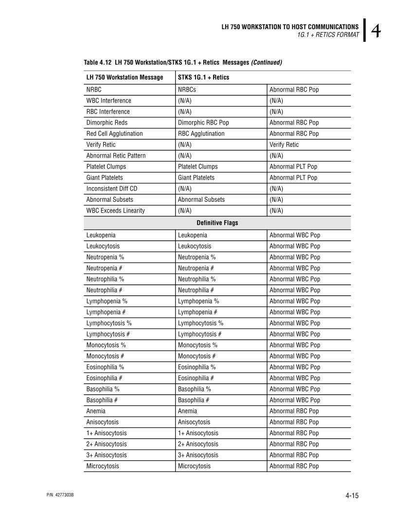
LH 750 WORKSTATION TO HOST COMMUNICATIONS1G.1 + RETICS FORMAT 4
NRBC NRBCs Abnormal RBC Pop
WBC Interference (N/A) (N/A)
RBC Interference (N/A) (N/A)
Dimorphic Reds Dimorphic RBC Pop Abnormal RBC Pop
Red Cell Agglutination RBC Agglutination Abnormal RBC Pop
Verify Retic (N/A) Verify Retic
Abnormal Retic Pattern (N/A) (N/A)
Platelet Clumps Platelet Clumps Abnormal PLT Pop
Giant Platelets Giant Platelets Abnormal PLT Pop
Inconsistent Diff CD (N/A) (N/A)
Abnormal Subsets Abnormal Subsets (N/A)
WBC Exceeds Linearity (N/A) (N/A)
Definitive Flags
Leukopenia Leukopenia Abnormal WBC Pop
Leukocytosis Leukocytosis Abnormal WBC Pop
Neutropenia % Neutropenia % Abnormal WBC Pop
Neutropenia # Neutropenia # Abnormal WBC Pop
Neutrophilia % Neutrophilia % Abnormal WBC Pop
Neutrophilia # Neutrophilia # Abnormal WBC Pop
Lymphopenia % Lymphopenia % Abnormal WBC Pop
Lymphopenia # Lymphopenia # Abnormal WBC Pop
Lymphocytosis % Lymphocytosis % Abnormal WBC Pop
Lymphocytosis # Lymphocytosis # Abnormal WBC Pop
Monocytosis % Monocytosis % Abnormal WBC Pop
Monocytosis # Monocytosis # Abnormal WBC Pop
Eosinophilia % Eosinophilia % Abnormal WBC Pop
Eosinophilia # Eosinophilia # Abnormal WBC Pop
Basophilia % Basophilia % Abnormal WBC Pop
Basophilia # Basophilia # Abnormal WBC Pop
Anemia Anemia Abnormal RBC Pop
Anisocytosis Anisocytosis Abnormal RBC Pop
1+ Anisocytosis 1+ Anisocytosis Abnormal RBC Pop
2+ Anisocytosis 2+ Anisocytosis Abnormal RBC Pop
3+ Anisocytosis 3+ Anisocytosis Abnormal RBC Pop
Microcytosis Microcytosis Abnormal RBC Pop
Table 4.12 LH 750 Workstation/STKS 1G.1 + Retics Messages (Continued)
LH 750 Workstation Message STKS 1G.1 + Retics
P/N 4277303B 4-15

LH 750 WORKSTATION TO HOST COMMUNICATIONS1G.1 + RETICS FORMAT
1+ Microcytosis 1+ Microcytosis Abnormal RBC Pop
2+ Microcytosis 2+ Microcytosis Abnormal RBC Pop
3+ Microcytosis 3+ Microcytosis Abnormal RBC Pop
Macrocytosis Macrocytosis Abnormal RBC Pop
1+ Macrocytosis 1+ Macrocytosis Abnormal RBC Pop
2+ Macrocytosis 2+ Macrocytosis Abnormal RBC Pop
3+ Macrocytosis 3+ Macrocytosis Abnormal RBC Pop
Hypochromia Hypochromia Abnormal RBC Pop
1+ Hypochromia 1+ Hypochromia Abnormal RBC Pop
2+ Hypochromia 2+ Hypochromia Abnormal RBC Pop
3+ Hypochromia 3+ Hypochromia Abnormal RBC Pop
(N/A) 1+ Poikilocytosis Abnormal RBC Pop
(N/A) 2+ Poikilocytosis Abnormal RBC Pop
(N/A) 3+ Poikilocytosis Abnormal RBC Pop
Erythrocytosis Erythrocytosis Abnormal RBC Pop
Pancytopenia Pancytopenia Abnormal WBC Pop andAbnormal RBC Pop andAbnormal PLT Pop
Reticulocytosis (N/A) (N/A)
Thrombocytopenia Thrombocytopenia Abnormal PLT Pop
Thrombocytosis Thrombocytosis Abnormal PLT Pop
Small Platelets Small Platelets Abnormal PLT Pop
Large Platelets Large Platelets Abnormal PLT Pop
H&H Check Failed (N/A) (N/A)
Parameter Flags
. . . . . . . . . . Abnormal WBC Pop and/orAbnormal RBC Pop and/orAbnormal PLT Pop and/orVerify Retic
+ + + + + + + + + + Abnormal WBC Pop and/orAbnormal RBC Pop and/orAbnormal PLT Pop
- - - - - - - - - - Abnormal WBC Pop and/orAbnormal RBC Pop and/orAbnormal PLT Pop and/orVerify Retic
Table 4.12 LH 750 Workstation/STKS 1G.1 + Retics Messages (Continued)
LH 750 Workstation Message STKS 1G.1 + Retics
P/N 4277303B 4-16

LH 750 WORKSTATION TO HOST COMMUNICATIONS1G.1 + RETICS FORMAT 4
Note: These flags will be produced only for the research parameters that are transmitted.
Demographics Group FieldsTable 4.13 identifies the field names, test types, and applicable format of Demographics Group transmissions.
????? ????? Abnormal WBC Pop and/orAbnormal RBC Pop and/orAbnormal PLT Pop and/orVerify Retic
: : : : : : : : : : Abnormal WBC Pop and/orAbnormal RBC Pop and/orAbnormal PLT Pop and/orVerify Retic
R R (N/A)
H H (N/A)
L L (N/A)
E E Edited Data
e e Edited Data
D (N/A) (N/A)
+ +++++ Abnormal WBC Pop and/orAbnormal RBC Pop and/orAbnormal PLT Pop and/orVerify Retic
Other Flags
Edited Data Edited Data (N/A)
Preliminary Report Preliminary Report (N/A)
Additional Test Report (N/A) (N/A)
Incomplete Collation Collate Failed (N/A)
SYSTEM ALARM (N/A) (N/A)
Completed Report (N/A) (N/A)
Blood Detector Disabled (N/A) (N/A)
Sample validated (N/A) (N/A)
Sample not validated (N/A) (N/A)
AutoValidated (N/A) (N/A)
STKS Messages
PCT IS FOR RESEARCH ONLY, NOT FOR DIAGNOSTIC PROCEDURES
PDW IS FOR RESEARCH ONLY, NOT FOR DIAGNOSTIC PROCEDURES
Table 4.12 LH 750 Workstation/STKS 1G.1 + Retics Messages (Continued)
LH 750 Workstation Message STKS 1G.1 + Retics
P/N 4277303B 4-17

LH 750 WORKSTATION TO HOST COMMUNICATIONS1G.1 + RETICS FORMAT
Note: This group will be transmitted only once per sample transmission.
Date of Birth Field:
User Field #1:
User Field #2:
Table 4.13 Demographics -- Group 7
Field Name Test Type 1G.1 + Retics
Date of Birth C, CD, CDR, CR, R X
User Field #1 C, CD, CDR, CR, R X
User Field #2 C, CD, CDR, CR, R X
User Field #3 C, CD, CDR, CR, R X
Sex C, CD, CDR, CR, R X
Location C, CD, CDR, CR, R X
Physician C, CD, CDR, CR, R X
User Date C, CD, CDR, CR, R X
User Time C, CD, CDR, CR, R X
X = Supported by the LH 750, “STKS 1G.1 + Retics” format.
Tag Data Format Data Length Comments
B I R T H N N / N N / N N N N 11 bytes Date of birth output is month/day/year, regardless of the system date configuration.The Date Of Birth Year is Always 4 Characters.
Tag Data Format Data Length Comments
U F 1 X X • • • X X X 17 bytes
Tag Data Format Data Length Comments
U F 2 X X • • • X X X 17 bytes
P/N 4277303B 4-18

LH 750 WORKSTATION TO HOST COMMUNICATIONS1G.1 + RETICS FORMAT 4
User Field #3:
Sex Field:
Location Field:
Physician Field:
User Date Field:
Tag Data Format Data Length Comments
U F 3 X X • • • X X X 17 bytes
Tag Data Format Data Length Comments
S E X A 2 bytes Data Value: ‘M’ Male ‘F’ Female ‘ ’ (20H) Unknown
Tag Data Format Data Length Comments
L O C A T I O N X X X • • • X X X 17 bytes
Tag Data Format Data Length Comments
P H Y S I C I A N X X X • • • X X X 22 bytes Concatenation of Physician last and first name separated by a comma and a space. Only the first 22 characters of the concatenated string are transmitted. Example: “Smith, Peter.”
Tag Data Format Data Length Comments
U D A T E N N / N N / N N 9 bytes Sample Drawn Date. Output format is month/day/year, regardless of the system date configuration.
P/N 4277303B 4-19

LH 750 WORKSTATION TO HOST COMMUNICATIONS1G.1 + RETICS FORMAT
User Time Field:
DF1 DataPlot Group FieldsThe 1G.1 + Retics format does not support transmission of this group. This group will be transmitted with field count of 00.
DF2 DataPlot Group FieldsThe 1G.1 + Retics format does not support transmission of this group. This group will be transmitted with field count of 00.
DIFF (VCS) Histogram Group Fields The 1G.1 + Retics format does not support transmission of this group. This group will be transmitted with field count of 00.
RBC Histogram Group FieldsTable 4.14 identifies the field names, test types, and applicable format of RBC Histogram Group Field transmissions.
If RBC histogram graphic transmission is disabled, this group is transmitted with a field of 00.
RBC Histogram Field:
Tag Data Format Data Length Comments
U T I M E N N : N N : N N 9 bytes Sample Drawn Time. Output is on 24 hours, regardless of the system time configuration. Time output is hours:minutes: seconds.
Table 4.14 RBC Histogram -- Group 11
Field Name Test Type 1G.1 + Retics
RBC Histogram C, CD, CDR, CR X
X = Supported by the LH 750, “STKS 1G.1 + Retics” format.
Tag Data Format Data Length Comments
R B C H H H H • • • H H H 512 bytes See Chapter 8 for graphic reconstruction.
P/N 4277303B 4-20

LH 750 WORKSTATION TO HOST COMMUNICATIONS1G.1 + RETICS FORMAT 4
PLT Histogram Group Fields Table 4.15 identifies the field names, test types, and applicable format of PLT Histogram Group Field transmissions.
If PLT histogram graphic transmission is disabled, this group is transmitted with a field of 00.
Note: When the PLT histogram graphic transmission is enabled the data in the PLTF field is always sent. Ignore the data sent in the PLTF field if an R flag is present for the PLT parameter sent in the CBC Parameter Group.
PLT Histogram Field:
PLT Fit Histogram Field:
RETIC Parameters Group FieldsTable 4.16 identifies the field names, test types, and applicable format of RETIC Parameters Group Field transmissions.
Table 4.15 PLT Histogram -- Group 12
Field Name Test Type 1G.1 + Retics
PLT Histogram C, CD, CDR, CR X
PLT Fit Histogram C, CD, CDR, CR X
X = Supported by the LH 750, “STKS 1G.1 + Retics” format.
Tag Data Format Data Length Comments
P L T H H H H • • • H H H 256 bytes See Chapter 8 for graphic reconstruction.
Tag Data Format Data Length Comments
P L T F H H H • • • H H H 512 bytes See Chapter 8 for graphic reconstruction.
Table 4.16 RETIC Parameters -- Group 13
Field Name Test Type 1G.1 + Retics
Retic Run Date CDR, CR, R X
Retic Run Time CDR, CR, R X
Retic ID CDR, CR, R X
Retic Cassette Position CDR, CR, R X
RET% CDR, CR, R, Edited X
RET# CDR, CR, R, Edited X
MRV CDR, CR, R, Edited X
P/N 4277303B 4-21

LH 750 WORKSTATION TO HOST COMMUNICATIONS1G.1 + RETICS FORMAT
Retic Run Date Field:
Retic Run Time Field:
Retic ID Field:
**Note: In the case of a “CBC/Retic” or “CBC/DIFF/Retic” sample run, the Sample ID transmitted in the ID1 field is duplicated in this field.
MI (now called IRF) CDR, CR, R, Edited X
X = Supported by the LH 750, STKS 1G.1 + Retics ” format.
Tag Data Format Data Length Comments
R E T D A T E N N / N N / N N 9 bytes Retic Run Date. Output is month/day/year, regardless of the system time configuration. Note: In the case of a “CBC/Retic” or “CBC/Diff/Retic” sample run, the Date and Time of the General Information group are duplicated in the RETDATE and RETTIME fields.
Tag Data Format Data Length Comments
R E T T I M E N N : N N : N N 9 bytes Retic Run Time. Output is on 24 hours, regardless of the system time configuration. Time output is hours:minutes:seconds.Note: In the case of a “CBC/Retic” or “CBC/Diff/Retic” sample run, the Date and Time of the General Information group are duplicated in the RETDATE and RETTIME fields.
Tag Data Format Data Length Comments
R I D X X • • • X X X 17 bytes See Note**
Table 4.16 RETIC Parameters -- Group 13 (Continued)
Field Name Test Type 1G.1 + Retics
P/N 4277303B 4-22

LH 750 WORKSTATION TO HOST COMMUNICATIONS1G.1 + RETICS FORMAT 4
Retic Cassette/Position Field:
Retic Parameter Results Field:
Result Format:**
The parameter result will be transmitted in the Reporting Units with the extra digit criteria selected on the LH 750 Workstation.
Numeric Data: **
If the numeric data of each format (for example, xx.xx) does not contain a decimal number, then it contains one of the following:
Flag Data: **
The flag data characters for the Retic Parameter Group fields will be as follows in Table 4.17:
Tag Data Format Data Length Comments
R C A S S / P O S X X X X / X X 8 bytes This field only applies to the 1G.1+ Retics host transmission protocol.
Tag Data Format Data Length Comments
A A A A X X X X X X A A A See “Data Format” column.
See Below.**
Result Comments
. . . . . Incomplete computation
: : : : : Flow cell clogged (Full clog, Partial clog 1 or Partial clog 2)
????? Invalid data: could not calculate RET#.+ + + + + Retic parameter result overrange
RET# > 999.9 x 10⁶cells/µLRET% > 100%
Table 4.17 Flag Data for Retic Parameter Group Fields
LH 750 Workstation Comments STKS 1G.1 + Retics
Review parameter R
Exceeds reference interval high limit H
Exceeds reference interval low limit L
Exceeds action high limit H
6 char numeric data max.
3 char flag data max.
P/N 4277303B 4-23

LH 750 WORKSTATION TO HOST COMMUNICATIONS1G.1 + RETICS FORMAT
If a Retic parameter is disabled, results for that parameter will NOT be transmitted. The IRF parameter result is transmitted with the label MI for backward compatibility reasons.
DF5 LS DataPlot Group Fields1G.1 + Retics format does not support transmission of this group. This group will be transmitted with field count of 00.
DF6 OP DataPlot Group Fields1G.1 + Retics format does not support transmission of this group. This group will be transmitted with field count of 00.
RETIC Histogram Group1G.1 + Retics format does not support transmission of this group. This group will be transmitted with field count of 00.
Exceeds action low limit L
Exceeds critical high limit H
Exceeds critical low limit L
Operator edited result E
Recalculated result from edited result e
Delta check failed
Partial aspiration/blood detector disabled R
Result exceeds linearity
Table 4.17 Flag Data for Retic Parameter Group Fields (Continued)
P/N 4277303B 4-24

LH 750 WORKSTATION TO HOST COMMUNICATIONSLH 750 WORKSTATION FORMAT 4
4.3 LH 750 WORKSTATION FORMAT
Message StructureThe Presentation deals with the high level format of the message. The data bytes of the transmission blocks, when collected together, exhibit the following high level format.
Preamble: The preamble marks the beginning of a message.
Transmission Identification:
The ASCII character "S" marks the beginning of the transmission.
TRANSMISSION TEST COUNT defines the number of tests that will be transmitted in this particular transmission. Not all Test Types are sent in all transmissions.
Each Transmission Test is identified by the order in which it appears after the preamble. The transmission test will never be transmitted out of order.
The Transmission Tests are up to 32 characters long. Table 4.18 lists the available Transmission Tests and Test IDs by Test Type.
Currently only manually entered data is transmitted.
PREAMBLE TRANSMISSION IDENTIFICATION TEST a IDENTIFICATION GROUP x1 • • • •• • • •
GROUP xn • • •
• • • TESTz IDENTIFICATION GROUP x1 • • • •• • • •
GROUP xn POSTAMBLE
CR
LF
CR
LF
CR
LF
CR
LF
CR
LF
CR
LF
-
-
-
-
-
-
-
-
-
-
-
-
-
-
CR
LF
S TRANSMISSIONTEST
COUNT
CR
LF
TRANSMISSIONTEST
1
CR
LF O O O
TRANSMISSIONTEST
N
CR
LF
Table 4.18 Transmission Tests and Test IDs by Test Type
Test Type Transmission Tests Test IDs
C “CBC” “CBC”CD “CBC”, “DIFF” “CBC”, “DIFF”R “RETIC” “RETIC”CR “CBC”, “RETIC” “CBC”, “RETIC”CDR “CBC”, “DIFF”, “RETIC” “CBC”, “DIFF”, “RETIC”C & CD Control “5CC” “CBC”, “DIFF”R Control “RETICC” “RETIC”CR Control “RETICC” “CBC”, “RETIC”CDR Control “RETICC” “CBC”, “DIFF”, “RETIC”CD Latex “DLATEX” “CBC”, “DIFF”CDR Latex “LATEXC” “CBC”, “DIFF”, “RETIC”Retic Latex “RLATEX” “RETIC”
P/N 4277303B 4-25

LH 750 WORKSTATION TO HOST COMMUNICATIONSLH 750 WORKSTATION FORMAT
Test Identification:
The ASCII character "T" marks the beginning of a test identification.
TEST ID, see Table 4.18.
GROUP COUNT defines the number of groups of data in this particular TEST Identification.
Group:
The ASCII character "G" marks the beginning of a group. A group follows the test identification fields.
GROUP NUMBER defines the group number. See Group Definition.
FIELD COUNT defines the number of fields in a particular group. See Field Count.
FIELD defines a field within a group. See Fields.
Note: When there is no data for a Group, the Group will not be sent.
Test Type Count:The transmission identification section has a Test Type Count that identifies the number of tests contained within the transmission. Valid test type count can be from 0-255. The test type count uses two characters to give the ASCII representation of the hexadecimal value.
Group Count:Each test identification has a Group Count that identifies the number of groups contained within the test. Valid group counts can be from 0-255. The group count uses two characters to give the ASCII representation of the hexadecimal value.
Group Number:Each group identifier has a Group Number that identifies the group number contained within the group identifier. Valid group number can be from 0-255. The group number uses two characters to give the ASCII representation of the hexadecimal value.
T TESTID
CR
LF
GROUPCOUNT
CR
LF
G GROUPNUMBER
CR
LF
FIELDCOUNT
CR
LF
FIELD1
CR
LF • • • •
FIELDN
CR
LF
MSCHAR
LSCHAR
Two-byte ASCII representation of Hex value between 00 and FF (0 to 255)
MSCHAR
LSCHAR
Two-byte ASCII representation of Hex value between 00 and FF (0 to 255)
MSCHAR
LSCHAR
Two-byte ASCII representation of Hex value between 00 and FF (0 to 255)
P/N 4277303B 4-26

LH 750 WORKSTATION TO HOST COMMUNICATIONSLH 750 WORKSTATION FORMAT 4
Field Count:Each Group has a Field Count that identifies the number of fields contained within the Group. Valid field counts can be from 0-255. The field count uses two characters to give the ASCII representation of the hexadecimal value.
Fields:Each Group is made up of variable length fields which may or may not be padded with SP (20H), or HT (09H) characters. A field may have a variable length tag preceding the data, separated by one or more SP (20H), or HT (09H) characters. Please note that all field transmissions will include a SP between the tag and data format (this will be implied in the following sections), as illustrated below:
The data portion of a field will only contain ASCII characters in the range of 20H to 7EH inclusive. Heading 6.2, VALID HOST COMMUNICATIONS ASCII CODES identifies the valid ASCII characters. Fields are separated with a CR (0DH) and an LF (0AH) character.
Note: A field's position within a Group must not be used to identify it. Fields within a Group may appear in any order or may be omitted. The CR/LF should be used to find fields and the Tag used to identify it.
ALL FIELDS ARE OF MAXIMUM 32 CHARACTERS LONG UNLESS OTHERWISE NOTED.
The following abbreviations are used to describe the fields:
SEP - one or more SP (20H) or HT (09H) characters.
The syntax for the Data Format of a field is:
Postamble:
The postamble marks the end of the current message.
MSCHAR
LSCHAR
Two-byte ASCII representation of Hex value between 00 and FF (0 to 255)
Tag Sep Data Format
T I M E N N : N N : N N
A - Alpha characters (a..z and A..Z and space) or (61H..7AH and 41H..5AH and 20H)
N - Numeric characters (0..9 and + - .) or (30H..39H and 2BH 2DH 2EH)
X - Printable characters (20H..7EH)
H - Hexadecimal characters
(0..9 and A..F)
O - Other characters (CR and LF) or (0DH and 0AH)
CR
LF
CR
LF
-
-
-
-
-
-
-
-
-
-
-
-
-
-
CR
LF
P/N 4277303B 4-27

LH 750 WORKSTATION TO HOST COMMUNICATIONSLH 750 WORKSTATION FORMAT
There are 24 groups defined in the current implementation of the LH 750 Workstation. Future revisions of LH 750 Workstation may include additional groups. Any future additions will not disrupt the order of the groups as currently defined.
Group Definition The abbreviations used to identify tests the group applies to are:
Table 4-19 lists the groups transmitted under 2A, 3A, GEN•S, and LH 750 Workstation formats.
C CBC
D DIFF
R RETICS
Table 4.19 Transmitted Groups
Group Number Group Name Tests LH 750 Workstation
1 General Information C D R X, *
2 CBC Parameters C X
3 DIFF Count Parameters D X
4 DIFF Percent Parameters D X
5 Comments C D R X, *
6 Definitive Flags C D R X, *
7 Suspect Flags C D R X, *
8 Conditional Flags C D R X, *
9 Other Flags C D R X, *
10 Demographics C D R X, *
14 RBC Histograms C X
15 PLT Histograms C X
16 RETIC Parameters R X
26 WBC Threshold C X
27 WBC Threshold Full Histogram C X
31 DIFF Latex Parameters D X
32 Retic Latex Parameters R X
34 Control Information C D R X
35 Control CBC Parameters C X
36 Control DIFF Count Parameters D X
37 Control DIFF Percent Parameters D X
38 Control Retics Parameters R X
50 DIFF Graphics D X
51 Retic Graphics R X
X = Supported by the LH 750, Workstation format.* = Indicates that the group information will not be repeated with every test.
P/N 4277303B 4-28

LH 750 WORKSTATION TO HOST COMMUNICATIONSLH 750 WORKSTATION FORMAT 4
Details of Group fields are defined in the following sections.
General Information Group FieldsTable 4.20 identifies the field names, test types, and applicable format of General Information transmissions.
Table 4.20 General Information -- Group 1
Field Name Test Type LH 750 Workstation
Run Date C, CD, CDR, CR, R X
Run Time C, CD, CDR, CR, R X
Sample Age C, CD, CDR, CR, R X
Sample ID C, CD, CDR, CR, R X
Pre Assigned Sample ID C, CD, CDR, CR, R X
Cassette / Position C, CD, CDR, CR, R X
Pre Assigned Cassette / Position C, CD, CDR, CR, R X
Sample ID Status C, CD, CDR, CR, R X
Cassette / Position Status C, CD, CDR, CR, R X
Sample Status C, CD, CDR, CR, R X
Instrument ID C, CD, CDR, CR, R X
Operator ID C, CD, CDR, CR, R X
Dilution Factor C ~
X = Supported by the LH 750, Workstation format.~ = New for the LH 750 Workstation format.
P/N 4277303B 4-29

LH 750 WORKSTATION TO HOST COMMUNICATIONSLH 750 WORKSTATION FORMAT
Run Date Field:
Run Time Field:
Sample Age Field:
Sample ID Field:
Tag Data Format Data Length Comments
D A T E N N / N N / N N 8 bytes Run Date. Output is month/day/year, regardless of the system date configuration.
Tag Data Format Data Length Comments
T I M E N N : N N : N N 8 bytes Run Time. Output is on 24 hours, regardless of the system time configuration. Time output is hours:minutes:seconds.
Tag Data Format Data Length Comments
S A N N N N : N N : N N 11 bytes Age of sample at run time. Format is DD HH:MM:SS. Computed from Draw Date and Draw Time. This field will not appear if draw date and time are invalid or after run date and time.
Tag Data Format Data Length Comments
I D 1 X X X • • • X X X X X 16 bytes Bar code read on tube by instrument at aspiration time, entered on the Diluter keypad for Manual mode aspiration, or ID generated by Auto-numbering feature.
P/N 4277303B 4-30

LH 750 WORKSTATION TO HOST COMMUNICATIONSLH 750 WORKSTATION FORMAT 4
Pre Assigned Sample ID Field:
Cassette/Position Field:
Pre-Assigned Cassette/Position Field:
Sample ID Status Field:
Tag Data Format Data Length Comments
P I D 1 X X X • • • X X X 16 bytes PRE ASSIGNED
SAMPLE ID
Tag Data Format Data Length Comments
C A S S P O S A C C C C P P 7 bytes CASS/POS output is cassette number (‘C’)/ cassette position (‘P’).Data values for 'A' are: ‘A’ for Automatic. ‘M’ for Manual.
Tag Data Format Data Length Comments
P C A S S P O S C C C C P P 6 bytes CASS/POS entered through ToDo list. Format is cassette number (‘C’)/ cassette position (‘P’). The sample mode is not specified at preassignment time.
Tag Data Format Data Length Comments
I D 1 S T A T U S A 1 byte Data Values: ‘P’ - positive ID ‘E’ - edited ID ‘N’ - Auto-numbered ID‘ ’ (20H) - not edited, not auto-numbered and not part of positive identification scheme.Precedence order is: ‘E’, ‘N’, ‘P’ and ‘ ’ (20H).
P/N 4277303B 4-31

LH 750 WORKSTATION TO HOST COMMUNICATIONSLH 750 WORKSTATION FORMAT
Cassette/Position Status Field:
Sample Status:
Instrument ID:
Operator ID:
Tag Data Format Data Length Comments
C / P S T A T U S A 1 byte Data Values: ‘P’ - positive ID ‘E’ - edited ID‘ ’ (20H) - not edited and not part of positive identification scheme.Precedence order is: ‘E’, ‘P’ and ‘ ’ (20H).
Tag Data Format Data Length Comments
S A S T A T U S X X • • • X X X 8 bytes See Table 4.21.
Table 4.21 Possible Values for Sample Status
Possible Value LH 750 Workstation Comments
PART ASP X Partial aspiration
NO READ X Bar code not read
NO MATCH X Match not found in ToDo list
MISMATCH X Non positive ID mismatch
INC COL X Incomplete collation
COMPLETE X No ToDo List errors
X in the LH 750 Workstation column = Supported by the LH 750 Workstation format.
Tag Data Format Data Length Comments
I N S T A A A • • • A A 16 bytes Identifies the LH 750 instrument this sample was run on.
Tag Data Format Data Length Comments
O P R A A A • • • A A 14 bytes Identifies the user logged on the LH 750 Workstation at the time this sample run was analyzed.
P/N 4277303B 4-32
LH 750 WORKSTATION TO HOST COMMUNICATIONSLH 750 WORKSTATION FORMAT 4
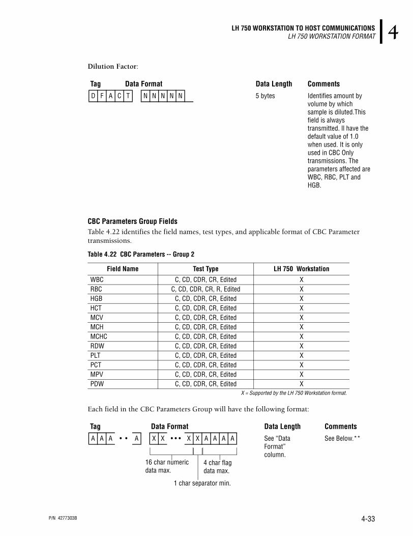
Dilution Factor:
CBC Parameters Group FieldsTable 4.22 identifies the field names, test types, and applicable format of CBC Parameter transmissions.
Each field in the CBC Parameters Group will have the following format:
Tag Data Format Data Length Comments
D F A C T N N N N N 5 bytes Identifies amount by volume by which sample is diluted.This field is always transmitted. ll have the default value of 1.0 when used. It is only used in CBC Only transmissions. The parameters affected are WBC, RBC, PLT and HGB.
Table 4.22 CBC Parameters -- Group 2
Field Name Test Type LH 750 Workstation
WBC C, CD, CDR, CR, Edited XRBC C, CD, CDR, CR, R, Edited XHGB C, CD, CDR, CR, Edited XHCT C, CD, CDR, CR, Edited XMCV C, CD, CDR, CR, Edited XMCH C, CD, CDR, CR, Edited XMCHC C, CD, CDR, CR, Edited XRDW C, CD, CDR, CR, Edited XPLT C, CD, CDR, CR, Edited XPCT C, CD, CDR, CR, Edited XMPV C, CD, CDR, CR, Edited XPDW C, CD, CDR, CR, Edited X
X = Supported by the LH 750 Workstation format.
Tag Data Format Data Length Comments
A A A • • A X X • • • X X A A A A See “Data Format” column.
See Below.**
16 char numeric data max.
4 char flag data max.
1 char separator min.
P/N 4277303B 4-33

LH 750 WORKSTATION TO HOST COMMUNICATIONSLH 750 WORKSTATION FORMAT
Result Format: **
The parameter result will be transmitted in the Reporting Units with the extra digit criteria selected on the LH 750 Workstation.
Numeric Data: **
If the numeric data of each format (for example, xx.xx) does not contain a decimal number, then it contains one of the following:
Flag Data: **
The flag data characters for the CBC Parameter Group Fields are as follows in Table 4.23:
DIFF Count Parameters Group FieldsTable 4.24 identifies the field names, test types, and applicable format of DIFF Count Parameter transmissions.
Result Comments
. . . . . Incomplete computation
+ + + + + Parameter overrange
- - - - - Parameter voteout
Table 4.23 Flag Data for CBC Parameter Group Fields
LH 750 Workstation Flags
4 (characters) Comments
R Review parameterH Exceeds reference interval high limitL Exceeds reference interval low limit
a H Exceeds action high limita L Exceeds action low limitc H Exceeds critical high limitc L Exceeds critical low limit
E Operator edited resulte Recalculated result from edited result* MCV threshold failure
D Delta check failedP Partial aspiration/blood detector disabled
+ Result exceeds linearity
Table 4.24 DIFF Count Parameters -- Group 3
Field Name Test Type LH 750 Workstation
LY# CD, CDR, Edited X
MO# CD, CDR, Edited X
P/N 4277303B 4-34

LH 750 WORKSTATION TO HOST COMMUNICATIONSLH 750 WORKSTATION FORMAT 4
Each field in the DIFF Count Parameters Group will have the following format:
Result Format: **
The parameter result will be transmitted in the Reporting Units with the extra digit criteria selected on the LH 750 Workstation.
Numeric Data: **
If the numeric data of each format (for example, xx.xx) does not contain a decimal number, then it contains one of the following:
Flag Data: **
The flag data characters for the DIFF Count Parameter Group fields are as follows in Table 4.25:
NE# CD, CDR, Edited X
EO# CD, CDR, Edited X
BA# CD, CDR, Edited X
NRBC# CD, CDR, Edited X
X = Supported by the LH 750 Workstation format.
Tag Data Format Data Length Comments
A A A • • A X X • • • X X A A A A See “Data Format” column.
See Below.**
Result Comments
. . . . . Incomplete computation
: : : : : Flow cell clogged (Full clog, Partial clog 1 or Partial clog 2)
????? Invalid data: could not calculate DIFF#.+ + + + + WBC parameter overrange or sum of DIFF# parameters is greater than 500.0 x
106 cells/µL (whole blood) or sum of DIFF# parameters is greater than 600.0 x 10⁶ cells/µL (diluted).
Table 4.24 DIFF Count Parameters -- Group 3 (Continued)
16 char numeric data max.
4 char flag data max.
1 char separator min.
P/N 4277303B 4-35

LH 750 WORKSTATION TO HOST COMMUNICATIONSLH 750 WORKSTATION FORMAT
DIFF Percent Parameters Group FieldsTable 4.26 identifies the field names, test types, and applicable format of DIFF Percent Parameter transmissions.
Each field in the DIFF Percent Parameters Group will have the following format:
Table 4.25 Flag Data for DIFF Count Parameter Group Fields
LH 750 Workstation Flags
(4 characters) Comments
R Review parameter: WBC threshold failure or WBC exceeds linearity or sum of DIFF% results exceeds 100.
H Exceeds reference interval high limitL Exceeds reference interval low limit
a H Exceeds action high limita L Exceeds action low limitc H Exceeds critical high limitc L Exceeds critical low limit
E Operator edited resulte Recalculated result from edited result
D Parameter value exceeds Delta check limitsP Partial aspiration/blood detector disabled
+ Result exceeds linearity
Table 4.26 DIFF Percent Parameters -- Group 4
Field Name Test Type GEN•S Workstation
LY% CD, CDR, Edited X
MO% CD, CDR, Edited X
NE% CD, CDR, Edited X
EO% CD, CDR, Edited X
BA% CD, CDR, Edited X
NRBC% CD, CDR, Edited X
X = Supported by the LH 750 Workstation format.
Tag Data Format Data Length Comments
A A A • • A X X • • • X X A A A A See “Data Format” column.
See Below.**
16 char numeric data max.
4 char flag data max.
1 char separator min.
P/N 4277303B 4-36

LH 750 WORKSTATION TO HOST COMMUNICATIONSLH 750 WORKSTATION FORMAT 4
Result Format: **
The parameter result will be transmitted in the Reporting Units with the extra digit criteria selected on the LH 750 Workstation.
Numeric Data: **
If the numeric data of each format (for example, xx.xx) does not contain a decimal number, then it contains one of the following:
Flag Data: **
The flag data characters for the DIFF Percent Parameter Group fields will be as follows in Table 4.27:
Result Comments
. . . . . Incomplete computation
: : : : : Flow cell clogged (Full clog, Partial clog 1 or Partial clog 2)
+ + + + + Sum of DIFF% parameter results is not equal to 100% +0.1, or DIFF# parameters is greater than 600.0 x 10⁶ cells/µL (predilute).
Table 4.27 Flag Data for DIFF Percent Parameter Group Fields
LH 750 Workstation Flags
(4 characters) Comments
R Review parameter
H Exceeds reference interval high limit
L Exceeds reference interval low limit
a H Exceeds action high limit
a L Exceeds action low limit
c H Exceeds critical high limit
c L Exceeds critical low limit
E Operator edited result
e Recalculated result from edited result
D Delta check failed
P Partial aspiration/blood detector disabled
+ Result exceeds linearity
P/N 4277303B 4-37

LH 750 WORKSTATION TO HOST COMMUNICATIONSLH 750 WORKSTATION FORMAT
Comment Group FieldsTable 4.28 identifies the field names, test types, and applicable format of Comment Group Field transmissions.
Note: This group will be transmitted only once per sample transmission.
The Comment Group can have a variable number of fields which consist of a variable number of bytes. Each Comment field is made up of an ASCII string identifying the appropriate flag.
Definitive Flags Group FieldsTable 4.29 identifies the field names, test types, and applicable format of Definitive Flag transmissions.
Note: This group will always be transmitted and will only be sent once per sample transmission.
** The possible definitive flags generated on the LH 750 Workstation are:
Table 4.28 Comment -- Group 5
Field Name Test Type LH 750 Workstation
Comment C, CD, CDR, CR, R X
X = Supported by the LH 750 Workstation format.
Tag Data Format Data Length Comments
C O M M E N T X X X • • • X X X 254 bytes STKS format is only 64 characters long.
Table 4.29 Definitive Flags -- Group 6
Field Name Test Type LH 750 Workstation
Definitive Flag C, CD, CDR, CR, R X
X = Supported by the LH 750 Workstation format.
Tag Data Format Data Length Comments
D E F I N I T X X X • • • X X X Up to 128 bytes
See Below.**
LH 750 Workstation MessagesLeukopeniaLeukocytosisNeutropenia %Neutropenia #Neutrophilia %Neutrophilia #Lymphopenia %Lymphopenia #Lymphocytosis %
P/N 4277303B 4-38

LH 750 WORKSTATION TO HOST COMMUNICATIONSLH 750 WORKSTATION FORMAT 4
Suspect Flags Group FieldsTable 4.30 identifies the field names, test types, and applicable format of Suspect Flag transmissions.
Note: This group will always be transmitted and will only be sent once per sample transmission.
Lymphocytosis #Monocytosis %Monocytosis #Eosinophilia %Eosinophilia #Basophilia %Basophilia #AnemiaAnisocytosis1+ Anisocytosis2+ Anisocytosis3+ AnisocytosisMicrocytosis1+ Microcytosis2+ Microcytosis3+ MicrocytosisMacrocytosis1+ Macrocytosis2+ Macrocytosis3+ MacrocytosisHypochromia1+ Hypochromia2+ Hypochromia3+ HypochromiaErythrocytosisPancytopeniaReticulocytosisThrombocytopeniaThrombocytosisSmall PlateletsLarge PlateletsH & H Check Failed
Table 4.30 Suspect Flags -- Group 7
Field Name Test Type LH 750 Workstation
Suspect Flag C, CD, CDR, CR, R XX = Supported by the LH 750 Workstation format.
LH 750 Workstation Messages (Continued)
P/N 4277303B 4-39

LH 750 WORKSTATION TO HOST COMMUNICATIONSLH 750 WORKSTATION FORMAT
** The possible Suspect flags generated on the LH 750 Workstation are:
Conditional Flags Group FieldsTable 4.31 identifies the field names, test types, and applicable format of Conditional Flag transmissions.
Note: This group will be transmitted with the first test only in each sample transmission.
Tag Data Format Data Length Comments
S U S P E C T X X X • • • X X X Up to 128 bytes
See Below.**
LH 750 Workstation MessagesLow Event #Verify DiffNe BlastsLy BlastsMo BlastsImm NE 1 Imm NE 2 Variant LY NRBCDimorphic RedsRed Cell AgglutinationVerify ReticAbnormal Retic PatternPlatelet ClumpsGiant PlateletsWBC InterferenceRBC InterferenceInconsistent Diff CD‡
WBC Exceeds Linearity
Table 4.31 Conditional Flags -- Group 8
Field Name Test Type LH 750 Workstation
Conditional Flag C, CD, CDR, CR, R XX = Supported by the LH 750 Workstation format.
Tag Data Format Data Length Comments
C O N D I T I O N X X X • • • X X X Up to 128 bytes
See Below.**
P/N 4277303B 4-40

LH 750 WORKSTATION TO HOST COMMUNICATIONSLH 750 WORKSTATION FORMAT 4
**The possible Conditional flags generated on the LH 750 Workstation are:
AutoValidation:
The auto validation flags show the validation status of test requests for a sample on printouts and within the results transmission. A functional example of the validation codes is described below.
A specimen is run in CDR mode with a CDR report format requested. Suppose results are acceptable for CBC and Retic, but not for the Diff (e.g., a Decision Rule fails, such as “If Blast [suspect flag], Perform Manual Diff”).
Note: The configuration of the Workstation affects the validation messages and codes.
The CBC and Retic test groups are AUTOVALIDATED, but the Diff group is NOT VALIDATED. There are two ways to indicate this. A conditional text message SAMPLE NOT VALIDATED would be transmitted. Additionally, validation codes C AV, R AV, D NV indicate the status of the individual test groups. The Diff can later be validated manually, resulting in SAMPLE VALIDATED, C AV, R AV, D V.
It is possible through use of the report format to have validation messages based on the report profile (report format). For example, using the scenario above, if a CBC report profile was requested, validation would be based solely on the results of the CBC group. For a complete explanation, refer to the LH 750 Workstation on-line help.
LH 750 Workstation Messages
Edited DataPreliminary ReportAdditional Test ReportIncomplete CollationSYSTEM ALARMCompleted ReportBlood Detector DisabledSample validatedSample not validatedAutoValidated
P/N 4277303B 4-41

LH 750 WORKSTATION TO HOST COMMUNICATIONSLH 750 WORKSTATION FORMAT
One of the conditional text messages below will always be transmitted.
r Sample not validated r Sample validated r AutoValidated
If “Enable Validation Codes” in Sytem Setup - [Communications] is checked (as described in Heading 3.16, ENABLE VALIDATION CODES), the individual test group validation status will be transmitted based on the profile selected and test mode run. The following columns display the possible codes transmitted for the individual groups:
Other Flags Group FieldsTable 4.32 identifies the field names, test types, and applicable format of Other Flag transmissions.
Note: This group will be transmitted only once in each sample transmission.
Validation Flags
AV AutoValidatedNV Not ValidatedV Validated (manually)
Validation CodesC CBC parameter blockD Diff parameter blockH H&H parameter blockR Retic parameter blockW WBC/Hgb/Plt parameter block
Sample Not Validated Sample Validated AutoValidated
C NV C V C AV
D NV D V D AV
R NV R V R AV
H NV H V H AV
W NV W V W AV
Table 4.32 Other Flags -- Group 9
Field Name Test Type LH 750 Workstation
Other Flag C, CD, CDR, CR, R XX = Supported by the LH 750 Workstation format.
Tag Data Format Data Length Comments
O T H E R X X X • • • X X X Up to 128 bytes
See Below.**
P/N 4277303B 4-42

LH 750 WORKSTATION TO HOST COMMUNICATIONSLH 750 WORKSTATION FORMAT 4
**The other possible flags generated on the LH 750 Workstation are:
Note: These flags will be produced only for the research parameters that are transmitted.
DemographicsTable 4.33 identifies the field names, test types, and applicable format of Demographics Group Field transmissions.
Note: This group will be transmitted only once per sample transmission.
LH 750 Workstation Messages
HLR% IS FOR RESEARCH ONLY, NOT FOR DIAGNOSTIC PROCEDURES
HLR# IS FOR RESEARCH ONLY, NOT FOR DIAGNOSTIC PROCEDURES
PCT IS FOR RESEARCH ONLY, NOT FOR DIAGNOSTIC PROCEDURES
PDW IS FOR RESEARCH ONLY, NOT FOR DIAGNOSTIC PROCEDURES
MSCV IS FOR RESEARCH ONLY, NOT FOR DIAGNOSTIC PROCEDURES
Table 4.33 Demographics -- Group 10
Field Name Test Type LH 750 Workstation
Date of Birth C, CD, CDR, CR, R X
User Field #1 C, CD, CDR, CR, R X
User Field #2 C, CD, CDR, CR, R X
User Field #3 C, CD, CDR, CR, R X
Sex C, CD, CDR, CR, R X
Location C, CD, CDR, CR, R X
Physician C, CD, CDR, CR, R X
Sample Drawn Date C, CD, CDR, CR, R X
Sample Drawn Time C, CD, CDR, CR, R X
Patient Identification C, CD, CDR, CR, R X
Patient Last Name C, CD, CDR, CR, R X
Patient First Name C, CD, CDR, CR, R X
Sequence Number C, CD, CDR, CR, R X
Profile C, CD, CDR, CR, R X
Number of slides made C, CD, CDR, CR, R X
Number of slides requested C, CD, CDR, CR, R X
Report Profile C, CD, CDR, CR, R XX = Supported by the LH 750 Workstation format.
P/N 4277303B 4-43

LH 750 WORKSTATION TO HOST COMMUNICATIONSLH 750 WORKSTATION FORMAT
Date of Birth Field:
User Field #1:
User Field #2:
User Field #3:
Sex Field:
Location Field:
Tag Data Format Data Length Comments
B I R T H N N / N N / N N N N 10 bytes Date of BirthOutput is month/day/year, regardless of the system date configuration.The Date Of Birth Year is Always 4 Characters.
Tag Data Format Data Length Comments
U F 1 X X X • • • X X X 16 bytes
Tag Data Format Data Length Comments
U F 2 X X X • • • X X X 16 bytes
Tag Data Format Data Length Comments
U F 3 X X X • • • X X X 16 bytes
Tag Data Format Data Length Comments
S E X A 1 byte Data Value: ‘M’ Male ‘F’ Female ‘U’ Unknown
Tag Data Format Data Length Comments
L O C A T I O N X X X • • • X X X 16 bytes
P/N 4277303B 4-44

LH 750 WORKSTATION TO HOST COMMUNICATIONSLH 750 WORKSTATION FORMAT 4
Physician Field:
Sample Drawn Date Field:
Sample Drawn Time Field:
Patient Identification:
Patient Last Name:
Tag Data Format Data Length Comments
P H Y S I C I A N X X X • • • X X X Up to 22 bytes Concatenation of Physician’s last and first name separated by a comma and a space. Example: “Smith, Peter.”
Tag Data Format Data Length Comments
D D N N / N N / N N 8 bytes Sample Drawn Date. Output is month/day/year, regardless of the system date configuration.
Tag Data Format Data Length Comments
D T N N : N N : N N 8 bytes Sample Drawn Time. Output is on 24 hours, regardless of the system time configuration. Time output is hours:minutes:seconds.
Tag Data Format Data Length Comments
P I D X X X • • • X X X 16 bytes
Tag Data Format Data Length Comments
P L N X X X • • • X X X 16 bytes
P/N 4277303B 4-45

LH 750 WORKSTATION TO HOST COMMUNICATIONSLH 750 WORKSTATION FORMAT
Patient First Name:
Sequence Number:
Number of Slides Made:
Number of Slides Requested:
Report Profile Field:
Profile Selection:
Data transmission reflects profile selection. Parameters not in the selected profile will not be transmitted. Test blocks (e.g., CBC, DIFF, etc.) which are not in the current profile will not be transmitted. If a complete test block is omitted from the current profile, the General Information Block (for sample identification) will still be sent.
Tag Data Format Data Length Comments
P F N X X X • • • X X X 16 bytes
Tag Data Format Data Length Comments
S E Q U E N C E X X X X X X 6 bytes
Tag Data Format Data Length Comments
S M N 1 byte Indicates how many slides were made for that sample on the LH 750 SlideMaker. Possible values are: 0 or 1. If 0, this field is not sent.
Tag Data Format Data Length Comments
S R N 1 byte Indicates how many slides were requested through preassignment in the ToDo list for that sample. Possible values are: 0 or 1.
Tag Data Format Data Length Comments
R P N N 2 bytes Report Profile possible values are from “01" to "10". Always transmitted.
P/N 4277303B 4-46

LH 750 WORKSTATION TO HOST COMMUNICATIONSLH 750 WORKSTATION FORMAT 4
RBC Histogram Group FieldsTable 4.34 identifies the field names, test types, and applicable format of RBC Histogram Group Field transmissions.
If CBC histograms graphic transmission is disabled, this group will NOT be transmitted.
RBC Histogram Field:
PLT Histogram Group FieldsTable 4.35 identifies the field names, test types, and applicable format of PLT Histogram Group Field transmissions.
If CBC histograms graphic transmission is disabled, this group will NOT be transmitted.
PLT Histogram Field:
Note: When the PLT histogram graphic transmission is enabled the data in the PLTF field is always sent. Ignore the data sent in the PLTF field if an R flag is present for the PLT parameter sent in the CBC Parameter Group.
PLT Fit Histogram Field:
Table 4.34 RBC Histogram -- Group 14
Field Name Test Type LH 750 Workstation
RBC Histogram C, CD, CDR, CR X
X = Supported by the LH 750 Workstation format.
Tag Data Format Data Length Comments
R B C H H H H • • • H H H 512 bytes See Chapter 8 for graphic construction.
Table 4.35 PLT Histogram -- Group 15
Field Name Test Type LH 750 Workstation
PLT Histogram C, CD, CDR, CR X
PLT Fit Histogram C, CD, CDR, CR X
X = Supported by the LH 750 Workstation format.
Tag Data Format Data Length Comments
P L T H H H H • • • H H H 256 bytes See Chapter 8 for graphic construction.
Tag Data Format Data Length Comments
P L T F H H H • • • H H H 512 bytes See Chapter 8 for graphic construction.
P/N 4277303B 4-47

LH 750 WORKSTATION TO HOST COMMUNICATIONSLH 750 WORKSTATION FORMAT
RETIC Parameters Group FieldsTable 4.36 identifies the field names, test types, and applicable format of RETIC Parameters Group Field transmissions.
Result Format: **
The parameter result will be transmitted in the Reporting Units with the extra digit criteria selected on the LH 750 Workstation.
Numeric Data: **
If the numeric data of each format (for example, xx.xx) does not contain a decimal number, then it contains one of the following:
Flag Data: **
The flag data characters for the Retic Parameter Group fields will be as follows in Table 4.37:
Table 4.36 RETIC Parameters -- Group 16
Field Name Test Type LH 750 Workstation
RET% CDR, CR, R, Edited X
RET# CDR, CR, R, Edited X
MRV CDR, CR, R, Edited X
MSCV CDR, CR, R, Edited X
IRF CDR, CR, R, Edited X
HLR% CDR, CR, R, Edited X
HLR# CDR, CR, R, Edited X
X = Supported by the LH 750 Workstation format.
Tag Data Format Data Length Comments
A A A • • A X X • • • X X A A A A See “Data Format” column.
See Below.**
Result Comments
. . . . . Incomplete computation
: : : : : Flow cell clogged (Full clog, Partial clog 1 or Partial clog 2)
????? Invalid data: could not calculate RET#.+ + + + + Retic parameter result overrange
RET# > 999.9 x 10⁶ cells/µLRET% > 100%
16 char numeric data max.
4 char flag data max.
1 char separator min.
P/N 4277303B 4-48

LH 750 WORKSTATION TO HOST COMMUNICATIONSLH 750 WORKSTATION FORMAT 4
MRV, MSCV, HLR%, HLR# and IRF results will be transmitted only if they have been enabled. If a Retic parameter is disabled, results for that parameter will NOT be transmitted.
The LH 750 Workstation does not support transmission of MI and OTHER fields. These fields will NOT be transmitted.
WBC Threshold Group FieldsTable 4.38 identifies the field names, test types, and applicable format of the WBC Threshold Monitor Group Field transmissions.
If CBC histograms graphic transmission is disabled, this group will NOT be transmitted.
WBC Threshold Monitor Field:
WBC Threshold Full Histogram Group FieldsThis group has the same description as WBC Threshold Group Fields with the exception that additional data elements are added.
Table 4.37 Flag Data for Retic Parameter Group Fields
LH 750 Workstation Flags
(4 characters) Comments
R Review parameter
H Exceeds reference interval high limit
L Exceeds reference interval low limit
a H Exceeds action high limit
a L Exceeds action low limit
c H Exceeds critical high limit
c L Exceeds critical low limit
E Operator edited result
e Recalculated result from edited result
D Delta check failed
P Partial aspiration/blood detector disabled
+ Result exceeds linearity
Table 4.38 WBC Threshold Monitor Group 26
Field Name Test Type LH 750S Workstation
WBC Threshold Monitor C, CD, CDR, CR X
X = Supported by the LH 750 Workstation format.
Tag Data Format Data Length Comments
W B C T H H H • • • H H H 112 bytes See Chapter 8 for graphic construction.
P/N 4277303B 4-49

LH 750 WORKSTATION TO HOST COMMUNICATIONSLH 750 WORKSTATION FORMAT
Table 4.38.1 WBC Full Histogram Monitor Group 27
WBC Threshold Full Monitor Field:
DIFF Latex Parameters Group FieldsTable 4.39 identifies the field names, test types, and applicable format of DIFF Latex Parameters Group transmissions.
Each field in the DIFF Latex Parameters Group will have the following format:
Result Format: **
The parameter result will be transmitted in the Reporting Units with the extra digit criteria selected on the LH 750 Workstation.
Field Name Test Type LH 750S Workstation
WBC Threshold Monitor C, CD, CDR, CR X
X = Supported by the LH 750 Workstation format.
Tag Data Format Data Length Comments
W B C F H H H • • • H H H 512 bytes See Chapter 8 for graphic construction.
Table 4.39 DIFF Latex Parameters -- Group 31
Field Name Test Type LH 750 Workstation
PRIMER F55, F57 X
V_MN F55, F57 X
C_MN F55, F57 X
S_MN F55, F57 X
V_CV F55, F57 X
C_CV F55, F57 X
S_CV F55, F57 X
X = Supported by the LH 750 Workstation format.
Tag Data Format Data Length Comments
A A A • • A X X • • • X X A See “Data Format” column.
See Below.**
16 char numeric data max.
1 char flag data max.
1 char separator min.
P/N 4277303B 4-50

LH 750 WORKSTATION TO HOST COMMUNICATIONSLH 750 WORKSTATION FORMAT 4
Numeric Data: **
If the numeric data of each format (for example, xx.xx) does not contain a decimal number, then it contains one of the following:
Flag Data: **
The flag data characters for the DIFF Latex Parameter Group fields will be as follows as in Table 4.40:
RETIC Latex Parameters Group FieldsTable 4.41 identifies the field names, test types, and applicable format of RETIC Latex Parameters Group transmissions.
Result Comments
. . . . . Incomplete computation
: : : : : Flow cell clogged (Full clog, Partial clog 1 or Partial clog 2)
Table 4.40 Flag Data for DIFF Latex Parameters Group Fields
LH 750 Workstation Flags (1 character) Comments
H Greater than expected value range.
L Less than expected value range.
Table 4.41 RETIC Latex Parameters -- Group 32
Field Name Test TypeLH 750
Workstation
PRIMER F56, F57 X
V_MN F56, F57 X
C_MN F56, F57 X
S_MN F56, F57 X
V_CV F56, F57 X
C_CV F56, F57, X
S_CV F56, F57 X
X = Supported by the LH 750 Workstation format.
P/N 4277303B 4-51

LH 750 WORKSTATION TO HOST COMMUNICATIONSLH 750 WORKSTATION FORMAT
Each field in the RETIC Latex Parameters Group will have the following format:
Result Format: **
The parameter result will be transmitted in the Reporting Units with the extra digit criteria selected on the LH 750 Workstation.
Numeric Data:**
If the numeric data of each format (for example, xx.xx) does not contain a decimal number, then it contains one of the following:
Flag Data: **
The flag data characters for the RETIC Latex Parameter Group fields will be as follows as in Table 4.42:
Table 4.43 identifies the field names, test types, and applicable format of Control Information Group transmissions
NOTE: Parameter selection does not affect control transmissions..
Tag Data Format Data Length Comments
A A A • • A X X • • • X X A See “Data Format” column.
See Below.**
Result Comments
. . . . . Incomplete computation
: : : : : Flow cell clogged (Full clog, Partial clog 1 or Partial clog 2)
Table 4.42 Flag Data for RETIC Latex Parameters Group Fields
LH 750 Workstation Flags (1 character) Comments
H Greater than expected value range.
L Less than expected value range.
Table 4.43 Control Information -- Group 34
Field Name Test Type LH 750 Workstation
Run number C, CD, CDR, CR, R, LATEX *
Lot number C, CD, CDR, CR, R, LATEX X
User Control Name C, CD, CDR, CR, R, LATEX X
Expiration Date C, CD, CDR, CR, R, LATEX X
16 char numeric data max.
1 char flag data max.
1 char separator min.
P/N 4277303B 4-52

LH 750 WORKSTATION TO HOST COMMUNICATIONSLH 750 WORKSTATION FORMAT 4
Run Number Field:
The LH 750 Workstation does not support transmission of this field. This field will NOT be transmitted.
Lot Number Field:
User Control Name Field:
Expiration Date Field:
Run Date C, CD, CDR, CR, R, LATEX X
Run Time C, CD, CDR, CR, R, LATEX X
Operator C, CD, CDR, CR, R, LATEX X
IQAP ID C, CD, CDR, CR, R, LATEX X
Delete Flag C, CD, CDR, CR, R, LATEX X
Shift C, CD, CDR, CR, R, LATEX X
Cassette / Position C, CD, CDR, CR, R, LATEX X
Reference RBC Count R X
X = Supported by the LH 750 Workstation format.* = Not supported by the LH 750 Workstation format.
Tag Data Format Data Length Comments
L O T # N N • • • N N 16 bytes
Tag Data Format Data Length Comments
U C N A M E X X X X X • • • X X 12 bytes
Tag Data Format Data Length Comments
E X P D A T E N N / N N / N N 8 bytes Expiration Date. is month/day/year, regardless of the system date configuration.
Table 4.43 Control Information -- Group 34 (Continued)
P/N 4277303B 4-53

LH 750 WORKSTATION TO HOST COMMUNICATIONSLH 750 WORKSTATION FORMAT
Run Date Field:
Run Time Field:
Operator Field:
IQAP ID Field:
Delete Flag Field:
Tag Data Format Data Length Comments
D A T E N N / N N / N N 8 bytes Run Date. Output is month/day/year, regardless of the system date configuration.
Tag Data Format Data Length Comments
T I M E N N : N N : N N 8 bytes Run Time. Output is on 24 hours, regardless of the system time configuration. Time output is hours:minutes:seconds
Tag Data Format Data Length Comments
O P E R A T O R X X • • • X 14 bytes
Tag Data Format Data Length Comments
I Q A P X X X • • • X 12 bytes
Tag Data Format Data Length Comments
D F L A G X 1 byte Run was excluded from statistical calculation on review screen.’Y’ = Run excluded.SP = Run not excluded.
P/N 4277303B 4-54

LH 750 WORKSTATION TO HOST COMMUNICATIONSLH 750 WORKSTATION FORMAT 4
Shift Field:
Cassette/Position Field:
Reference RBC Count Field:
Reference WBC Count Field:
Control CBC Parameters Group FieldsTable 4.44 identifies the field names, test types, and applicable format of Control CBC Parameters Group transmissions
NOTE: Parameter selection does not affect control transmissions..
Tag Data Format Data Length Comments
S H I F T X 1 byte Possible values are 0, 1, 2, or 3. Reference the Online Help for more information.
Tag Data Format Data Length Comments
C A S S P O S A C C C C P P 7 bytes CASS/POS output is cassette number (‘C’) / cassette position (‘P’).Data values for ‘A’ are: ‘A’ - Automatic sampling ‘M’ - Manual sampling
Tag Data Format Data Length Comments
R R B C X X X X X 5 characters numeric data max.
Tag Data Format Data Length Comments
R W B C X X X X X 5 characters numeric data max.
Table 4.44 Control CBC Parameters -- Group 35
Field Name Test Type LH 750 Workstation
WBC C, CD, CDR, CR X
RBC C, CD, CDR, CR X
P/N 4277303B 4-55

LH 750 WORKSTATION TO HOST COMMUNICATIONSLH 750 WORKSTATION FORMAT
Each field in the Control CBC Parameters Group will have the following format:
Result Format: **
The parameter result will be transmitted in the Reporting Units with the extra digit criteria selected on the LH 750 Workstation.
Numeric Data:**
If the numeric data of each format (for example, xx.xx) does not contain a decimal number, then it contains one of the following:
HGB C, CD, CDR, CR X
HCT C, CD, CDR, CR X
MCV C, CD, CDR, CR X
MCH C, CD, CDR, CR X
MCHC C, CD, CDR, CR X
RDW C, CD, CDR, CR X
PLT C, CD, CDR, CR X
PCT C, CD, CDR, CR X
MPV C, CD, CDR, CR X
PDW C, CD, CDR, CR X
X = Supported by the LH 750 Workstation format.
Tag Data Format Data Length CommentsA A A • • A X X • • • X X A A A A See “Data
Format” column.
See Below.**
Result Comments
. . . . . Incomplete computation
- - - - - Total voteout
+ + + + + Overrange
Table 4.44 Control CBC Parameters -- Group 35 (Continued)
16 char numeric data max.
4 char flag data max.
1 char separator min.
P/N 4277303B 4-56

LH 750 WORKSTATION TO HOST COMMUNICATIONSLH 750 WORKSTATION FORMAT 4
Flag Data: **
The flag data characters for the Control CBC Parameter Group fields will be as follows as in Table 4.45:
Control DIFF Count Parameters Group FieldsTable 4.46 identifies the field names, test types, and applicable format of Control DIFF Count Parameters Group transmissions.
NOTE: Parameter selection does not affect control transmissions.
Each field in the Control DIFF count Parameters Group will have the following format:
Table 4.45 Flag Data for Control CBC Parameters Group Fields
LH 750 Workstation Flags
(4 characters) Comments
R Review parameter.H Exceeds expected range high limitL Exceeds expected range low limit
* MCV threshold failureP Partial aspiration/blood detector disabled
+ Result exceeds linearity
Table 4.46 Control DIFF Count Parameters -- Group 36
Field Name Test Type LH 750 Workstation
LY# CD, CDR XMO# CD, CDR XNE# CD, CDR XEO# CD, CDR XBA# CD, CDR X
NRBC# CD, CDRX = Supported by the LH 750 Workstation format.
Tag Data Format Data Length Comments
A A A • • A X X • • • X X A A A A See “Data Format” column.
See Below.**
16 char numeric data max.
4 char flag data max.
1 char separator min.
P/N 4277303B 4-57

LH 750 WORKSTATION TO HOST COMMUNICATIONSLH 750 WORKSTATION FORMAT
Result Format: **
The parameter result will be transmitted in the Reporting Units with the extra digit criteria selected on the LH 750Workstation.
Numeric Data:**
If the numeric data of each format (for example, xx.xx) does not contain a decimal number, then it contains one of the following:
Flag Data: **
The flag data characters for the DIFF Count Parameter Group fields will be as follows in Table 4.47:
Control DIFF Percent Parameters Group FieldsTable 4.48 identifies the field names, test types, and applicable format of Control DIFF Percent Parameters Group transmissions.
NOTE: Parameter selection does not affect control transmissions.
Result Comments
. . . . . Incomplete computation
????? Invalid data: could not calculate DIFF#.
: : : : : Flow cell clogged (Full clog, Partial clog 1 or Partial clog 2)
Table 4.47 Flag Data for DIFF Count Parameter Group Fields
LH 750 Workstation Flags (4 characters) Comments
R Review parameter.
H Exceeds expected range high limit
L Exceeds expected range low limit
P Partial aspiration/blood detector disabled
+ Result exceeds linearity
Table 4.48 Control DIFF Percent Parameters -- Group 37
Field Name Test Type LH 750 Workstation
LY% CD, CDR X
MO% CD, CDR X
NE% CD, CDR X
EO% CD, CDR X
BA% CD, CDR X
NRBC% CD, CDR
X = Supported by the LH 750 Workstation format.
P/N 4277303B 4-58

LH 750 WORKSTATION TO HOST COMMUNICATIONSLH 750 WORKSTATION FORMAT 4
Each field in the Control DIFF Percent Parameters Group will have the following format:
Result Format: **
The parameter result will be transmitted in the Reporting Units with the extra digit criteria selected on the LH 750 Workstation.
Numeric Data:**
If the numeric data of each format (for example, xx.xx) does not contain a decimal number, then it contains one of the following:
Flag Data: **
The flag data characters for the DIFF percent Parameter Group fields will be as follows in Table 4.49:
Control RETIC Parameters Group FieldsTable 4.50 identifies the field names, test types, and applicable format of Control RETIC Parameters Group transmissions.
Tag Data Format Data Length Comments
A A A • • A X X • • • X X A A A A See “Data Format” column.
See Below.**
Result Comments
. . . . . Incomplete computation
+++++ Sum of DIFF% parameter results not equal to 100% +0.1: : : : : Flow cell clogged (Full clog, Partial clog 1 or Partial clog 2)
Table 4.49 Flag Data for Diff Percent Parameter Group Fields
LH 750 Workstation Flags
(4 characters) Comments
R Review parameter.H Exceeds expected range high limitL Exceeds expected range low limit
P Partial aspiration/blood detector disabled
16 char numeric data max.
4 char flag data max.
1 char separator min.
P/N 4277303B 4-59

LH 750 WORKSTATION TO HOST COMMUNICATIONSLH 750 WORKSTATION FORMAT
NOTE: Parameter selection does not affect control transmissions.
Each field in the Control RETICS Parameters Group will have the following format:
Result Format: **
The parameter result will be transmitted in the Reporting Units with the extra digit criteria selected on the LH 750 Workstation.
Numeric Data:**
If the numeric data of each format (for example, xx.xx) does not contain a decimal number, then it contains one of the following:
Flag Data: **
The flag data characters for the Control RETIC Parameter Group fields will be as follows in Table 4.51:
Table 4.50 Control RETIC Parameters -- Group 38
Field Name Test Type LH 750 Workstation
RET% CDR, CR, R XRET# CDR, CR, R XMRV CDR, CR, R XIRF CDR, CR, R XMI CDR, CR, R *OTHER CDR, CR, R *
X = Supported by the LH 750 Workstation format.* = Not supported by the LH 750 Workstation format.
Tag Data Format Data Length Comments
A A A • • A X X • • • X X A A A A See “Data Format” column.
See Below.**
Result Comments
. . . . . Incomplete computation
????? Invalid data: could not calculate RET#.+ + + + + Retic parameter result overrange
RET# >999.9 x 10⁶cells/µLRET% >100%
: : : : : Flow cell clogged (Full clog, Partial clog 1 or Partial clog 2)
16 char numeric data max.
4 char flag data max.
1 char separator min.
P/N 4277303B 4-60

LH 750 WORKSTATION TO HOST COMMUNICATIONSLH 750 WORKSTATION FORMAT 4
DIFF GraphicsTable 4.52 identifies the field names, test types, and applicable format of DIFF Graphics Group Field transmissions.
If DIFF graphic transmission is disabled, this group will NOT be transmitted.
DIFF Graphics Field:
Retic GraphicsTable 4.53 identifies the field names, test types, and applicable format of Retic Graphics Group Field transmissions.
If Retic graphic transmission is disabled, this group will NOT be transmitted.
Retic Graphics Field:
Table 4.51 Flag Data for Control RETIC Parameter Group Fields
LH 750 Workstation Flags
(4 characters) Comments
R Review parameter.H Exceeds expected range high limitL Exceeds expected range low limit
P Partial aspiration/blood detector disabled
Table 4.52 DIFF DataPlot -- Group 50
Field Name Test Type LH 750 Workstation
DIFF graphics CD, CDR X
X = Supported by the LH 750 Workstation format.
Tag Data Format Data Length Comments
D I F F H H H • • • H H H Variable .
Table 4.53 Retic DataPlot -- Group 51
Field Name Test Type LH 750 Workstation
Retic graphics CDR, CR, R X
X = Supported by the LH 750 Workstation format.
Tag Data Format Data Length Comments
R E T G H H H • • • H H H Variable
P/N 4277303B 4-61

LH 750 WORKSTATION TO HOST COMMUNICATIONSHOST PARSING OF TRANSMITTED DATA
4.4 HOST PARSING OF TRANSMITTED DATACoulter reserves the right to make additions, deletions, and/or change the order of parameters in future releases. However, if the communications protocol is adhered to as specified in this document, future releases will not require reprogramming on the part of the host.
We do not guarantee the appearance of any particular parameter. Neither do we guarantee any particular order to the transmitted data. This ensures that any program written to parse an existing transmission format will not have to be restructured if it is designed properly.
Note that each information item is an ASCII character string. Because of delimiters, field terminators and so on, these information strings may be extracted from the transmitted data block without having to identify the strings at that time.
P/N 4277303B 4-62

5
5HOST TO LH 750 WORKSTATION COMMUNICATIONS (HOST ToDo LIST)5.1 DATA-LINK
ProtocolThe LH 750 Workstation requires full handshaking to receive data. The protocol is similar to that used for LH 750 Workstation to Host transmissions with the SYN character replaced with the ENQ character.
The data is transmitted as a sequence of up to 255 blocks of data of 256 [or 128] bytes each. Generally, these blocks contain 256 data bytes each, but due to the unique needs of differing hosts, the system is configurable to allow shorter blocks with 128 data bytes. The final block must be padded with ASCII spaces (20H) if it has less than the number of data bytes necessary to complete.
.
Host Computer (SENDER) LH 750 Workstation (RECEIVER)SYN indicates receiver busy, prepare to receive sample(s) record.
2-byte data block
(NAK indicates receiver abort}
After each block
“All Done”
ENQ
ENQ/SYN
X XACK/NAK
Send block and await response. Repeat data block and response until done.
STX 2-byteblk number
Exactly 256 or 128 data bytes
4-byteCRC
ETX
ACK/NAK/ENQ
ENQ
ACK/NAK/ENQ
DLE
Accept / Reject
PN 4277303B 5-1

HOST TO LH 750 WORKSTATION COMMUNICATIONS (HOST ToDo LIST)DATA-LINK
The LH 750 Workstation ACKs or NAKs each block sent by the Host. If the LH 750 Workstation NAKs a block, the Host must retransmit that block. If the Workstation NAKs the same block 3 times in a row, the Workstation aborts and is then prepared to receive the next transmission. If the LH 750 Workstation sends an ENQ after the reception of any block, the Host must retransmit all blocks starting with the first, but should not resend the initial ENQ character. Some common reasons why the LH 750 Workstation would NAK a block are: bad block sequence number, incorrect block byte count, CRC mismatch, etc. If the Data Link transmission successfully completes, the LH 750 Workstation then transmits a DLE character followed by a single ASCII character indicating whether the transmission is accepted or rejected at the presentation level. The ASCII characters following the DLE are listed below:
The following demonstrates the above protocol:
Host Computer (SENDER) LH 750 Workstation (RECEIVER)
ENQ (ready)
send data blocks
ENQ (go ahead) orSYN (busy)
# of data blocks(2 bytes)
ACK (read to receive) or NAK (receiver abort)
DataBlock
ACK (block received ok) or for each blockNAK (retransmit this block) orENQ (retransmit all blocks, starting with block #1)
P/N 4277303B 5-2

HOST TO LH 750 WORKSTATION COMMUNICATIONS (HOST ToDo LIST)DATA-LINK 5
Return Codes
For the Delete request, codes A, B, C, and D still apply. In addition to these, the following codes are returned for the Delete Function only:
“G” Error in Patient ID field format
“H” Error in Test field format
“I” ToDo list Item not Deleted
•••
ENQ (all done)
ACK (transmission accepted) orNAK (transmission rejected) (Presentation Level Response)DLE‘A’ (transmission accepted, ready for next) or‘B’ (transmission accepted, do NOT send more) or‘C’ (transmission rejected, retry) or‘D’ (transmission rejected, abandon) or*‘E’ (transmission rejected, at least one duplicate
pending test request in sample request)‘F’ (transmission rejected, patient ID already exists in LH 750 database)
*Please Note: User may select to replace DLE ‘E’ with DLE ‘C’ in the LIS section of the Communications Screen in the LH 750 Workstation System Setup. This option is provided for backward compatibility and is not the optimum configuration for the interface.
P/N 4277303B 5-3

HOST TO LH 750 WORKSTATION COMMUNICATIONS (HOST ToDo LIST)PRESENTATION
Data Block Structure
5.2 PRESENTATION
Message Structure
The data which is blocked for transmission will consist of a sequence of ASCII lines each terminated by a CR/LF pair. The block boundaries for the 256 [or 128] byte blocks would have no special significance with respect to this data. The data may be thought of as a large ASCII buffer which is being sent 256 [or 128] bytes at a time.
Byte # # of bytes
1 STX 1 byte
2 BLK NBR MS CHAR 1 byte
3 BLK NBR LS CHAR 1 byte
4 DATA BYTES•
•
•
256 (128) Cbytes R
C
259 (131)
260 (132) CRC MSB MS CHAR 1 byte
261 (133) CRC MSB LS CHAR 1 byte
262 (134) CRC LSB MS CHAR 1 byte
263 (135) CRC LSB LS CHAR 1 byte
264 (136) ETX 1 byte
PREAMBLE INTRO FIELD 1 0 0 0 FIELD N
PreambleField
SOH CR LF2-bytenum fields
“00” to “FF”
P/N 4277303B 5-4

HOST TO LH 750 WORKSTATION COMMUNICATIONS (HOST ToDo LIST)PRESENTATION 5
The 2-byte num fields indicate the number of fields that follow the preamble field, that is, the intro field plus all data fields.
The record type indicates the target data set, for example, "WL" for ToDo list (TDL).
The operation code indicates the action to be performed:
The ASCII Tag is unique to each field within each record type.
DLE Responses From The Workstation And Effects After A ToDo List DownloadINTRO FIELD: AD Add or Update
1. Conditions prior to ToDo List Download - No samples are in the ToDo list with the same Primary Identifier(s) and no samples are in the ToDo List or Completed list with the same Patient ID.
a. Workstation Response - DLE A or DLE B
b. Effect - Add the downloaded request to the ToDo list.
2. Conditions prior to ToDo List Download - No sample(s) are in the ToDo list with the same Primary Identifier(s) but there are sample(s) are in the ToDo List and/or Completed list with the same Patient ID.
a. Workstation Response - DLE A or DLE B
b. Effect - Add the downloaded request to the ToDo list. Update the Last Name, First Name, Gender and Birth Date for all samples in the ToDo List and/or Completed list that have the same Patient ID.
3. Conditions prior to ToDo List Download - Sample(s) are in the ToDo list with the same Primary Identifier(s) and sample(s) are in the ToDo List and/or Completed list with the same Patient ID.
a. Workstation Response - DLE+E, or DLE+C if the workstation was configured to replace DLE+E with DLE+C
b. Effect - Update the Last Name, First Name, Gender and Birth Date for all samples in the ToDo list and/or Completed List that have the same Patient ID.
IntroField
CR LF2-byterecord type
2-byteoperation
For ToDo list“WL”
“AD” “UN” “RU” “DE”
EachField
ASCIITag
ASCIIData
CR LFRepeat until all fields given.
P/N 4277303B 5-5

HOST TO LH 750 WORKSTATION COMMUNICATIONS (HOST ToDo LIST)PRESENTATION
4. Conditions prior to ToDo List Download - The downloaded ToDo list format is not correct.
a. Workstation Response - DLE+C or DLE+D.
b. Effect - No modifications are made to the ToDo list or to the Completed list.
INTRO FIELD: UN Unique
1. Conditions prior to ToDo List Download - No samples are in the ToDo list with the same Primary Identifier(s) and no samples are in the ToDo List or Completed list with the same Patient ID. If samples are deleted or edited to remove the patient ID then the Workstation will have to be rebooted before downloading a sample with the same patient ID using the Unique intro tag. Logging off and back on is not sufficient to allow the reuse of a patient ID.
a. Workstation Response - DLE A or DLE B
b. Effect - Add the downloaded request to the ToDo list.
2. Conditions prior to ToDo List Download - No sample(s) are in the ToDo list with the same Primary Identifier(s) but there are sample(s) are in the ToDo List and/or Completed list with the same Patient ID.
a. Workstation Response - DLE F
b. Effect - No modifications are made to the ToDo list or to the Completed list.
3. Conditions prior to ToDo List Download - Sample(s) are in the ToDo list with the same Primary Identifier(s) and sample(s) are in the ToDo List and/or Completed list with the same Patient ID.
a. Workstation Response - DLE F
b. Effect - No modifications are made to the ToDo list or to the Completed list.
4. Conditions prior to ToDo List Download - The downloaded ToDo list format is not correct.
a. Workstation Response - DLE+C or DLE+D.
b. Effect - No modifications are made to the ToDo list or to the Completed list.
INTRO FIELD: RU Reuse
1. Conditions prior to ToDo List Download - No samples are in the ToDo list with the same Primary Identifier(s) and no samples are in the ToDo List or Completed list with the same Patient ID.
a. Workstation Response - DLE A or DLE B
b. Effect - Add the downloaded request to the ToDo list.
2. Conditions prior to ToDo List Download - No sample(s) are in the ToDo list with the same Primary Identifier(s) but there are sample(s) in the ToDo List and/or Completed list with the same Patient ID.
a. Workstation Response - DLE A or DLE B
P/N 4277303B 5-6

HOST TO LH 750 WORKSTATION COMMUNICATIONS (HOST ToDo LIST)MESSAGE DEFINITION 5
b. Effect - Add the downloaded request to the ToDo list. Remove the Last Name, First Name, Gender and Birth Date for all samples in the ToDo List and/or Completed list
3. Conditions prior to ToDo List Download - Sample(s) are in the ToDo list with the same Primary Identifier(s) and sample(s) are in the ToDo List and/or Completed list with the same Patient ID.
a. Workstation Response - DLE+E, or DLE+C if the workstation was configured to replace DLE+E with DLE+C
b. Effect - Remove the Last Name, First Name, Gender and Birth Date for all samples in the ToDo list and the Completed list that have the same Patient ID.
4. Conditions prior to ToDo List Download -. The downloaded ToDo list format is not correct.
a. Workstation Response - DLE+C or DLE+D.
b. Effect - No modifications are made to the ToDo list or to the Completed list
INTRO FIELD: DE Delete
DE in this field is a command by the host to delete one or more test entries in the LH 750 Workstation ToDo List. See Section 5.4, Delete Message, for a specification for this function.
5.3 MESSAGE DEFINITIONTable 5.1 lists the fields and the format to which they apply. The table also identifies fields that require data transmission in another field in order to be included in the test request. If data is not in the associated field, the LH 750 Workstation ignores the field. For example, if a Patient ID is not transmitted, the LH 750 Workstation ignores any data included in the Patient Last Name field.
After the Table is the list of possible fields, their field width and the appropriate ASCII Tag to be used for transmission.
A field will have a variable length TAG preceding the data separated by one or more SP (20H) or HT (09H) characters. A field tag must be transmitted with data. If a field tag is transmitted without data, the Workstation rejects the whole sample request. If an invalid or unrecognized tag is transmitted, the LH 750 Workstation will ignore the field and go to the next field provided that the field to be ignored has the correct field format (i.e. is terminated by a CRLF).
Table 5.1 Message Definition Table
Field NameLH 750
WorkstationField
Requires
Patient ID X Test
Patient Last Name X Patient ID
Patient First Name X Patient ID
Sequence Number X Test
Birth Date X Patient ID
P/N 4277303B 5-7

HOST TO LH 750 WORKSTATION COMMUNICATIONS (HOST ToDo LIST)MESSAGE DEFINITION
Only one sample’s demographics can be sent per transmission.
FIELDS CANNOT HAVE LEADING OR TRAILING SPACES (MESSAGE WILL BE REJECTED).
Sex X Patient ID
Location X Test
Physician Last Name X Test
Physician First Name X Test
User Field 1 X Test
User Field 2 X Test
User Field 3 X Test
Comments X Test
Report Profile X Test
Sample Drawn Date X Test
Sample Drawn Time X Test
Test X
Slide Request X Test
X = Supported by the LH 750 Workstation format.
Table 5.1 Message Definition Table (Continued)
P/N 4277303B 5-8

HOST TO LH 750 WORKSTATION COMMUNICATIONS (HOST ToDo LIST)MESSAGE DEFINITION 5
Patient ID Field:
Patient Last Name Field:
Patient First Name Field:
Sequence Number Field:
Tag Data Format Data Length Comments
I D X X X • • • X X 16 bytes Patient ID is 16 characters, alphanumeric.Value in Intro field determines what is done:AD UN RU See Heading 5.2, PRESENTATION for details.
Tag Data Format Data Length Comments
P L X X X • • • X X 16 bytes Patient Last Name is 16 characters, alphanumeric.Requires Patient ID.
Tag Data Format Data Length Comments
P F X X X • • • X X 16 bytes Patient First Name is 16 characters, alphanumeric.Requires Patient ID.
Tag Data Format Data Length Comments
S N N N N N N N 6 bytes Sequence Number
P/N 4277303B 5-9

HOST TO LH 750 WORKSTATION COMMUNICATIONS (HOST ToDo LIST)MESSAGE DEFINITION
Birth Date Field:
Sex Field:
Location Field:
Physician Last Name Field:
Physician First Name Field:
Tag Data Format Data Length Comments
B D N N / N N / N N N N 10 bytes Date format must be the same as the Workstation configuration. Any of the following formats can be used. DD/MM/YYYY, MM/DD/YYYY, or YYYY/MM/DD. Requires Patient ID.
Tag Data Format Data Length Comments
S X A 1 byte Data Value: ‘M’ - Male ‘F’ - Female ‘U’ - Unknown ‘O’ - Other (equivalent to ‘Unknown’)Requires Patient ID.
Tag Data Format Data Length Comments
L N X X X • • • X X 16 bytes
Tag Data Format Data Length Comments
D L X X X • • • X X 16 bytes Physician Last Name is 16 characters, alphanumeric.
Tag Data Format Data Length Comments
D F X X X • • • X X 16 bytes Physician First Name is 16 characters, alphanumeric.
P/N 4277303B 5-10

HOST TO LH 750 WORKSTATION COMMUNICATIONS (HOST ToDo LIST)MESSAGE DEFINITION 5
User Field 1 Field:
User Field 2 Field:
User Field 3 Field:
Comments Field:
Report Profile Field:
Tag Data Format Data Length Comments
U 1 X X X • • • X X 16 bytes Requires Test.
Tag Data Format Data Length Comments
U 2 X X X • • • X X 16 bytes Requires Test.
Tag Data Format Data Length Comments
U 3 X X X • • • X X 16 bytes Requires Test.
Tag Data Format Data Length Comments
C M X X X • • • X X 64 bytes Requires Test.
Tag Data Format Data Length Comments
R P N N 2 bytes Report Profile possible values are from “01" to "10".
P/N 4277303B 5-11

HOST TO LH 750 WORKSTATION COMMUNICATIONS (HOST ToDo LIST)MESSAGE DEFINITION
Sample Drawn Date Field:
Sample Drawn Time Field:
Profile Selection:
Data transmission reflects profile selection. Parameters not in the selected profile will not be transmitted. Test blocks (e.g., CBC, DIFF, etc.) which are not in the current profile will not be transmitted. If a complete test block is omitted from the current profile, the General Information Block (for sample identification) will still be sent.
Tag Data Format Data Length Comments
E D N N / N N / N N 8 bytes Date format must be the same as the Workstation configuration. Any of the following formats can be used. DD/MM/YY, MM/DD/YY, or YY/MM/DD. Requires Test.
Tag Data Format Data Length Comments
E T N N : N N 5 bytes Time output is on 24 hours, regardless of the system time configuration. Time output is hours:minutes.Requires Test.
P/N 4277303B 5-12

HOST TO LH 750 WORKSTATION COMMUNICATIONS (HOST ToDo LIST)MESSAGE DEFINITION 5
Test Field:
Slide Request Field:
Tag Data Format Data Length Comments
T S X X X • • • X X Up to 64 bytes This field indicates test requests. Format for a test request is: ”TEST,TUBE ID,CASS/POS” or ”TEST,TUBE ID,” or ”TEST,CASS/POS” . The commas are required as separators. Note that a comma is required after TUBE ID, even if it is not followed by a CASS/POS.See Table 5.2 for possible values.Required for transmission.The TS tag can repeat itself for as many tests as may be required. Only one test request can be sent per test tag occurrence. See Table 5.3 for sample and text request combinations.
Tag Data Format Data Length Comments
S R N 1 byte Valid entries are 0 and 1. For a Retic Mode request, the only valid entry for the Slide Request field is 0. If a value > 1 is sent, this is converted by the LH 750 Workstation to a value of 1.
P/N 4277303B 5-13

HOST TO LH 750 WORKSTATION COMMUNICATIONS (HOST ToDo LIST)MESSAGE DEFINITION
Table 5.2 Possible Values and Examples of Test Requests
Test Tag LH 750 Workstation Comment Example
CBC X CBC only test. “TS CBC,000101” “TS CBC,123456789012,” “TS CBC,123456789012,000101”
DIFF X CBC/DIFF test “TS DIFF,000101”“TS DIFF,123456789012,”“TS DIFF,123456789012,000101”
CDR X CBC/DIFF/Retic test “TS CDR,000101”“TS CDR,123456789012,”“TS CDR,123456789012,000101”
RETIC X Retic only test “TS RETIC,000101”“TS RETIC,123456789012,”“TS RETIC,123456789012,000101”
CR X CBC/Retic test “TS CR,000101”“TS CR,123456789012,”“TS CR,123456789012,000101”
X = Supported by the LH 750 Workstation format. *CASS POS is six characters TUBEID is no more than 16 characters
Table 5.3 Possible Combinations of Sample Requests with Multiple Test Requests
Test CBC DIFF CDR RETIC CR
CBC NO NO NO YES NO
DIFF NO NO NO YES NO
CDR NO NO NO NO NO
RETIC * YES YES NO NO NO
CR NO NO NO NO NO
* For a Retic Mode request, the only valid entry for the Slide Request field is 0.
P/N 4277303B 5-14

HOST TO LH 750 WORKSTATION COMMUNICATIONS (HOST ToDo LIST)Delete Message 5
A sample request with multiple test requests for CBC+DIFF or Retic only, would appear similar to the following:
.
.
.“TS DIFF,123456,000101”“TS RETIC,123,000203”...
5.4 Delete MessageWhen the Intro Field of a ToDo List upload from the host contains the Operation string “DE” (see page 5-77), the host has requested the deletion of one or more entries from the LH 750 Workstation ToDo List. The LH 750 Workstation allows deletion of preassigned test orders from the ToDo List by the host according to;
Patient ID
Sample ID Number
Cassette Position
Test Type
The Sample ID, Cassette Position and Test Type are part of the Test Field. The formats for the Patient ID and Test fields are described in 5.3 Message Definitions. The Patient ID and Test field are the only fields of the message definition section used in the Deleted Function. All others are ignored and need not be sent.
In the Deleted context, an ID or TS Tag followed by a CRLF will be interpreted as an empty Patient ID or Test Field.
If the Patient ID field and the Test field are empty, the Workstation deletes all entries from the ToDo List.
According to the above definition, these fields are empty when they have the following form:
It is possible for a pre assignment to be made to the ToDo List that has no Patient ID. If the host requests deletion of this pre assignment, or some part of it, the transmission of the deletion request must contain no Patient ID field. Note that this is not the same as an empty Patient ID field. No field with an ID tag should be sent. See example 10.
On page 5-83, the Data Format of the Test field is given as “TEST,TUBE ID, CASS/POS” or “TEST,TUBE ID,” or “TEST,CASS/POS”. The TUBE ID here is the SAMPLE ID. The commas
Patient ID Field: I D CR LF See Pages 5-5 & 5-9
Test Field: T S CR LF See Pages 5-5 & 5-13
P/N 4277303B 5-15

HOST TO LH 750 WORKSTATION COMMUNICATIONS (HOST ToDo LIST)Delete Message
are required as separators. Note that a comma is required after TUBE ID even if it is not followed by a CASS/POS. This Test Field Data Format has additional flexibility in the Delete Function only.
NOTE: “TEST,TUBE ID,” represents an empty CASS/POS indicator and “TEST,CASS/POS” represents and empty TUBE ID indicator.
Additional format flexibility in the Delete Function only is as follows.
“,TUBE,ID,CASS/POS”shall represent an empty TEST indicator.
“,,CASS/POS” shall represent empty TEST and TUBE ID indictors.
“,TUBE ID,” shall represent empty TEST and CASS/POS indicators.
“TEST,,” shall represent empty TUBE ID and CASS/POS indicators.
“,,” shall represent empty TEST,TUBE ID, and CASS/POS indicators.
NOTE: The last entry has the same effect as an empty Test field.
In the Delete context, an Empty Indicator is interpreted to refer to all values of that indicator relative to the next highest indicator in the ToDo List. For example; If the TUBE ID indicator is not empty and the TEST indicator is empty, this is interpreted to mean “delete all TEST’s preassigned to this TUBE ID”. An empty Test field refers to all preassigned tests relative to a given Patient ID (this is also true for the Test Field Data Format”,,”).
It should be noted again, that if there is no Patient ID field, this is not the same as an empty Patient ID field. This is interpreted as referring to a preassignment with no Patient ID.
The following table illustrates the variables.
P/N 4277303B 5-16

HOST TO LH 750 WORKSTATION COMMUNICATIONS (HOST ToDo LIST)Delete Message 5
* This field was not transmitted.
NOTE: TS_<CR><LF> is to TS_, , <CR><LF>
Table 5.4 Patient ID Deletions
Example Patient ID Test ID Action
1 ID_<CR><LF> TS_<CR>< LF> Delete all entries of all types in ToDo list.
2 ID_123456<CR><LF>
TS_<CR><LF> Delete all Patient ID “123456” entries of all test types in ToDo list.
3 ID_<CR><LF> TS_CBC,,<CR><LF> Delete all CBC tests from all Patient ID entries in ToDo list.
4 ID_123456<CR><LF>
TS_CBC,,<CR><LF> Delete all CBC tests from Patient ID 123456.
5 ID_123456<CR><LF>
TS_CDR,987654,<CR>< LF> Delete CDR test from Tube ID “987654”and all Cass/Pos for Patient ID 123456.
6 ID_123456<CR><LF>
TS_CDR,,001001,<CR>< LF> Delete all Patient ID “123456” entries of CDR test type in ToDo list with Cass/Pos “001001”.
7 ID_123456<CR><LF>
TS_CBC,987654,001001, <CR>< LF>
Delete all Patient ID “123456” entries of CBC test type in ToDo list with Tube ID “987654” and Cass/Pos “001001”.
8 ID_<CR><LF> TS_CBC,001001 Delete CBC test for all the Tube IDs with Cass/Pos “001001”for all Patient IDs.
9 ID_<CR><LF> * Delete all entries of all types in ToDo list.
10 * TS_ , ,<CR><LF> Delete all entries in ToDo list without Patient IDs.
11 ID_<CR><LF> TS_ ,ID12345,<CR><LF> Delete Tube ID from all test types.
P/N 4277303B 5-17

HOST TO LH 750 WORKSTATION COMMUNICATIONS (HOST ToDo LIST)Delete Message
P/N 4277303B 5-18

6
6ASCII Tables6.1 7-BIT ASCII CODES
6.2 VALID HOST COMMUNICATIONS ASCII CODES
Bold used only for Data-link control.
+ ) ) ) ) ) ) 0 0 0 0 1 1 1 1* Ú
+) ) ) ) ) 0 0 1 1 0 0 1 1
* +Ú
) ) ) ) 0 1 0 1 0 1 0 1
� � �
7 6 5 4 3 2 1
X X X 0 0 0 0 NUL DLE SP 0 @ P ` pX X X 0 0 0 1 SOH DC1 ! 1 A Q a qX X X 0 0 1 0 STX DC2 “ 2 B R b rX X X 0 0 1 1 ETX DC3 # 3 C S c sX X X 0 1 0 0 EOT DC4 $ 4 D T d tX X X 0 1 0 1 ENQ NAK % 5 E U e uX X X 0 1 1 0 ACK SYN & 6 F V f vX X X 0 1 1 1 BEL ETB ‘ 7 G W g wX X X 1 0 0 0 BS CAN ( 8 H X h xX X X 1 0 0 1 HT EM ) 9 I Y I yX X X 1 0 1 0 LF SUB * : J Z j zX X X 1 0 1 1 VT ESC + ; K [ k {X X X 1 1 0 0 FF FS , < L \ l |X X X 1 1 0 1 CR GS - = M ] m }X X X 1 1 1 0 SO RS . > N ^ n `X X X 1 1 1 1 SI US / ? O _ o DEL
+ ) ) ) ) ) ) 0 0 0 0 1 1 1 1* Ú
+) ) ) ) ) 0 0 1 1 0 0 1 1
* +Ú
) ) ) ) 0 1 0 1 0 1 0 1
� � �
7 6 5 4 3 2 1X X X 0 0 0 0 DLE SP 0 @ P ` pX X X 0 0 0 1 SOH DC1 ! 1 A Q a qX X X 0 0 1 0 STX “ 2 B R b rX X X 0 0 1 1 ETX # 3 C S c sX X X 0 1 0 0 $ 4 D T d tX X X 0 1 0 1 ENQ NAK % 5 E U e uX X X 0 1 1 0 ACK SYN & 6 F V f vX X X 0 1 1 1 ‘ 7 G W g wX X X 1 0 0 0 ( 8 H X h xX X X 1 0 0 1 HT ) 9 I Y I yX X X 1 0 1 0 LF * : J Z j zX X X 1 0 1 1 + ; K [ k {X X X 1 1 0 0 , < L \ l |X X X 1 1 0 1 CR - = M ] m }X X X 1 1 1 0 . > N ^ n `X X X 1 1 1 1 / ? O _ o DEL
PN 4277303B 6-1

ASCII TablesVALID HOST COMMUNICATIONS ASCII CODES
P/N 4277303B 6-2

7
7CRC7.1 CRC ALGORITHMThe CRC algorithm used is a modified CCITT CRC16 algorithm and is the same as used in the STKS™ analyzer.
The polynomial for this algorithm is: X**16 + X**12 + X**5 + 1.
Note: D = current data byte that is input to the algorithm.
CRCLSB,CRCMSB = data byte. Least significant and most significant CRC accumulator bytes.
x>>n means x is shifted n bits to right or is the same as x divided by 2n.
x<<n means x is shifted n bits to left or is the same as x multiplied by 2n.
//------------------------------------------------------------------------------------------------------------------
at beginning,CRCLSB = 0FFH (octal 377) (decimal 255) CRCMSB = 0FFH (octal 377) (decimal 255)
then for each data byte in a block,X = D XOR CRCMSBX = X XOR ( X >> 4 )CRCMSB = CRCLSB XOR ( X >> 3 ) XOR ( X << 4 )CRCLSB = X XOR ( X << 5 )
and at end,CRCLSB = CRCLSB XOR 0FFHCRCMSB = CRCMSB XOR 0FFH
//------------------------------------------------------------------------------------------------------------------
PN 4277303B 7-1

CRCCRC EXAMPLE WRITTEN IN ASM86
7.2 CRC EXAMPLE WRITTEN IN ASM86The following is an example of CRC16 code written in assembler for 8086:
;-------------------------------------------------------------------------------------------------------------------
GET_CRC_BYTES PROCPUSH CX
;;This is the Algorithm used (CCITT CRC16):;; X = D XOR CRCMSB; X = X XOR ( X >> 4 ); CRCMSB = CRCLSB XOR ( X >> 3 ) XOR ( X << 4 ); CRCLSB = X XOR ( X << 5 );;Data arrives in AL.;Finished CRC is in BX ( BH = MSB, BL = LSB );To use this algorithm:; 1. Initialize BX to 0FFFFH.; 2. At end:; CRCLSB = CRCLSB XOR 0FFH.; CRCMSB = CRCMSB XOR OFFH.;
XOR AL,BH ;X=D XOR CRCMSB (AL=X) <--- 1
MOV AH,AL ;Save X for later in AHSHR AL,4 ;Then AL=X >> 4
XOR AL,AH ;X=X XOR ( X >> 4 )<--- 2
MOV AH,AL ;Save XMOV CH,AL ;Save XSHR AL,3 ;Then AL= ( X >> 3 )XOR AL,BL ;AL=CRCLSB XOR ( X >> 3 )SHL AH,4 ;AH=( X << 4 )
XOR AL,AH ;CRCMSB=CRCLSB XORMOV BH,AL ; ( X >> 3 ) XOR ( X << 4 )<--- 3
MOV AL,CH ;Recover X in ALSHL AL,5 ;AL=( X << 5 )XOR AL,CH ;AL=X XOR ( X << 5 )
MOV BL,AL ;CRCLSB=X XOR ( X << 5 )<--- 4
POP CXRET
GET_CRC_BYTES ENDP;-------------------------------------------------------------------------------------------------------------------
P/N 4277303B 7-2

CRCCRC EXAMPLE WRITTEN IN C 7
7.3 CRC EXAMPLE WRITTEN IN CThe following is an example of CRC16 code written in C.//------------------------------------------------------------------------------------------------------------------void calc_crc ( unsigned char DataByte ){DataByte ^= crcmsb;
DataByte ^= ( DataByte / 16 ); crcmsb = crclsb ^ ( DataByte / 8 ) ^ ( DataByte * 16 ); crclsb = DataByte ^ ( DataByte * 32 );
}//------------------------------------------------------------------------------------------------------------------
P/N 4277303B 7-3

CRCCRC EXAMPLE WRITTEN IN C
P/N 4277303B 7-4

8
8GRAPHIC RECONSTRUCTION8.1 RBC, WBC THRESHOLD, AND PLT HISTOGRAMSThe histograms display a simple line graph which is representative of the count of events occurring in each A/D channel (or voltage level). The histograms are transmitted as 512 ASCII bytes for RBC (256 bytes for PLT, 112 bytes for WBC and 512 bytes for WBC Full Histogram) representing a 256-byte for RBC (128-byte for PLT, 56 bytes for WBC and 256 bytes for WBC Full Histogram) Hex array. It takes two ASCII bytes to represent one Hex byte.
Each Hex byte represents a scaled count for each channel 0-255 (14-142 for PLT). The histograms can be constructed by plotting the count for each channel then drawing a line between plots.
To display (or print) the histogram you must plot the channel vs. count. The channel represents the X-axis while the count is the Y-axis (see Figure 8.1). There are 128 channels for the platelet histogram, 256 channels for RBC, 56 channels for WBC and 256 channels for WBC Full Histogram. The value range is 14-255 (0D-FF hex) for the platelet histogram and 0-255 (00-FF hex) for the WBC and RBC histograms.
Figure 8.1 Plotting RBC, WBC Threshold and PLT Histograms
8.2 LH 750 DATAPLOT FORMATThe 2-dimensional dataplots communicate a greater amount of information to the viewer about the events. The following sections describe the format of the dataplot data and provide a how-to example of displaying the dataplot data on a raster device such as a video display or printer.
DataplotsThe dataplots consist of two major components: dataplot data and rendering information. Taken together, these two components allow a receiving application to display the dataplots in the same fashion as the LH 750 Workstation.
The dataplot portion of the host transmission consists of a dataplot data header and one dataplot data block.
CHANNEL
COUNT
<< x
y
PN 4277303B 8-1

GRAPHIC RECONSTRUCTIONLH 750 DATAPLOT FORMAT
Dataplot Data HeaderThe dataplot data header tells the receiving application how large the dataplot transmission is and how many dataplot data blocks are contained in the transmission. A complete dataplot transmission, including the dataplot data header, is illustrated in Figure 8.2.
Figure 8.2 Dataplot Transmission
Dataplot Data Header ElementsThe dataplot data header contains two elements: the total length of the dataplot transmission and the number of dataplot data blocks in the transmission. The data are represented as one 16-bit integer which indicates the total size of the dataplot transmission and one 8-bit integer which indicates the total number of dataplot data blocks in the transmission (between 1 and 4). Only one block is supported currently, but up to four may be used in future software. See Figure 8.3 for details.
Figure 8.3 Dataplot Data Header
Dataplot Data BlockThe dataplot data block contains both the rendering information and the actual 2-dimensional dataplot data. Each dataplot data block is composed of four subsections: dataplot data block header, rendering information block, dataplot header and the dataplot data. Figure 8.4 illustrates the dataplot data block format.
Figure 8.4 Dataplot Data Block Format
Dataplot data header
Dataplot data block
Transmission Length LSB
Transmission Length MSB
Total Number of Dataplot data blocks
Dataplot data block header
Rendering information block
Dataplot header
Dataplot data
P/N 4277303B 8-2
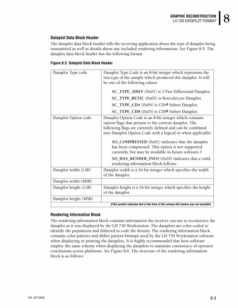
GRAPHIC RECONSTRUCTIONLH 750 DATAPLOT FORMAT 8
Dataplot Data Block HeaderThe dataplot data block header tells the receiving application about the type of dataplot being transmitted as well as details about any included rendering information. See Figure 8.5. The dataplot data block header has the following format:
Figure 8.5 Dataplot Data Block Header
Rendering Information BlockThe rendering information block contains information the receiver can use to reconstruct the dataplot as it was displayed by the LH 750 Workstation. The dataplots are color-coded to identify the population and dithered to code the density. The rendering information block contains color palettes and dither pattern bitmaps used by the LH 750 Workstation software when displaying or printing the dataplots. It is highly recommended that host software employ the same scheme when displaying the dataplots to maintain consistency of operator conclusions across platforms. See Figure 8.6. The structure of the rendering information block is as follows:
Dataplot Type code Dataplot Type Code is an 8-bit integer which represents the run type of the sample which produced this dataplot. It will be one of the following values:
SC_TYPE_5DIFF (0x01) is 5 Part Differential Dataplot.
SC_TYPE_RETIC (0x02) is Reticulocyte Dataplot.
SC_TYPE_CD4 (0x04) is CD4‡ Subset Dataplot.
SC_TYPE_CD8 (0x05) is CD8‡ Subset Dataplot.
Dataplot Option code Dataplot Option Code is an 8-bit integer which contains option flags that pertain to the current dataplot. The following flags are currently defined and can be combined into Dataplot Option Code with a logical or when applicable:
SO_COMPRESSED (0x01) indicates that the dataplot has been compressed. This option is not supported currently, but may be available in future software.‡
SO_HAS_RENDER_INFO (0x02) indicates that a valid rendering information block follows.
Dataplot width (LSB) Dataplot width is a 16-bit integer which specifies the width of the dataplot.
Dataplot width (MSB)
Dataplot height (LSB) Dataplot height is a 16-bit integer which specifies the height of the dataplot.
Dataplot height (MSB)‡This symbol indicates that at the time of this release this feature was not available.
P/N 4277303B 8-3

GRAPHIC RECONSTRUCTIONLH 750 DATAPLOT FORMAT
Figure 8.6 Rendering Information Block
Rendering Information Block HeaderThe rendering information block header contains fields which indicate the size and format of the bitmaps and the color palette. It is sent on the first transmission after a user log-on and a shutdown/restart occurs. As notification is not provided when a shutdown/restart is initiated, the rendering block transmission cannot be predicted in advance. Figure 8.7 is an illustration of the rendering information block header.
Figure 8.7 Rendering Information Block Header Format
Color PaletteEach color palette entry contains three 8-bit integers which represent the red, green and blue values for that index as shown in Figure 8.8.
Figure 8.8 Palette Table Entry
Dithered Display Bitmap LibraryThe dithered display bitmap library contains the dithering bitmaps used by the LH 750 Workstation to display the dataplots. They indicate the density of a specific cell population. Receiving applications should use these bitmaps when generating displays to ensure that host
Rendering information block header
Color palette
Dithered display bitmap library
Rendering information block options
Rendering Information Block Options may be one or more of the following flags:
RH_OPTIONS_NONE (0x00) indicates that no options are set.
It is an 8-bit integer.
Number of color palette table entries
Number of Color Palette Table Entries is the number of entries in the color palette. It is an 8-bit integer.
Number of bitmap library entries
Number of Bitmap Library Entries is the number of bitmap patterns contained in the Dithered display bitmap library. It is an 8-bit integer.
Bitmap width in pixels Bitmap Width in Pixels is the width of each bitmap in pixels. It is an 8-bit integer.
Bitmap height in pixels Bitmap Height in Pixels is the height of each bitmap in pixels. It is an 8-bit integer.
Red Component
Green Component
Blue Component
P/N 4277303B 8-4
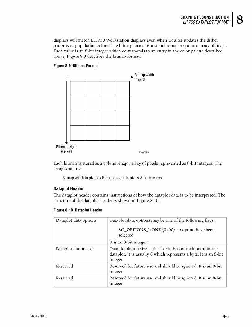
GRAPHIC RECONSTRUCTIONLH 750 DATAPLOT FORMAT 8
displays will match LH 750 Workstation displays even when Coulter updates the dither patterns or population colors. The bitmap format is a standard raster scanned array of pixels. Each value is an 8-bit integer which corresponds to an entry in the color palette described above. Figure 8.9 describes the bitmap format.
Figure 8.9 Bitmap Format
Each bitmap is stored as a column-major array of pixels represented as 8-bit integers. The array contains:
Bitmap width in pixels x Bitmap height in pixels 8-bit integers
Dataplot HeaderThe dataplot header contains instructions of how the dataplot data is to be interpreted. The structure of the dataplot header is shown in Figure 8.10.
Figure 8.10 Dataplot Header
Dataplot data options Dataplot data options may be one of the following flags:
SO_OPTIONS_NONE (0x00) no option have been selected.
It is an 8-bit integer.
Dataplot datum size Dataplot datum size is the size in bits of each point in the dataplot. It is usually 8 which represents a byte. It is an 8-bit integer.
Reserved Reserved for future use and should be ignored. It is an 8-bit integer.
Reserved Reserved for future use and should be ignored. It is an 8-bit integer.
0Bitmap widthin pixels
Bitmap heightin pixels 7306002B
P/N 4277303B 8-5

GRAPHIC RECONSTRUCTIONLH 750 DATAPLOT FORMAT
The format of the dataplot is shown in Figure 8.11.
Figure 8.11 Dataplot Data Format
0 Scatterplotwidth
Scatterplotheight 7306003B
P/N 4277303B 8-6

PN 4277303B
All other trademarks, service marks, products, or services are trademarks or registered trademarks of their respective holders.
TRADEMARKS
5C, AccuGate, the BECKMAN COULTER logo, BECKMAN COULTER, COULTER, COULTER CLENZ, COULTER COUNTER, GEN•S, GEN•S SM, GEN•S ST, LIN-C, LYSE S, ISOTON, S-CAL, ZAP-OGLOBIN and IntelliKinetics are trademarks of Beckman Coulter, Inc.

Copyright © Beckman Coulter, Inc. 2001-2002All Rights ReservedPrinted on Recycled Paper
COULTER CORPORATIONA Beckman Coulter CompanyMiami, Florida 33196-2500 USA
Come visit us at www.beckmancoulter.com
s Getting StartedPN 4277302
Overview of system hardware and software
s Host TransmissionPN 4277303
Specifications for transmitting to a host computer
s ReferencePN 4277248
Use and Function • Installation • Operation Principles • Specifications/Characteristics • Precautions/Hazards • References • Glossary • Index
Available in hard copy by request.
s Operator’s GuidePN 4277249
Controls and Indicators • Startup • QC • Sample Analysis • Data Analysis • Shutdown • Analyzer CRT Functions • Workstation • Run Samples Display • To Do List • Database • Controls • Setup • Appendices
Available in hard copy by request.
s Special Procedures and TroubleshootingPN 4277250
Calibration • Cleaning Procedures • Replace/Adjust Procedures • Troubleshooting • Error Messages
Available in hard copy by request.
s Master IndexPN 4277301
Combined index for Reference, Operator’s Guide, and Special Procedures and Troubleshooting manuals. Comes with hard copy of Operator’s Guide and Special Procedures and Troubleshooting.
s SlideMaker Operator’s GuidePN 4277299
Use and Function • Installation • Operation Principles • Specifications/Characteristics • Operating Procedures • Cleaning and Replacement Procedures • Troubleshooting • References • Index
Available in hard copy by request.
s SlideStainer Operator’s GuidePN 4277300
Use and Function • Installation • Operation Principles • Specifications/Characteristics • Operating Procedures • Cleaning and Replacement Procedures • Troubleshooting • References • Index
Available in hard copy by request.
The Getting Started booklet and the Host Transmission manual come with your LH 750 System.
The information in the Reference manual, Operator’s Guide, Special Procedures and Troubleshooting manual, the SlideMaker Operator’s Guide and the SlideStainer Operator’s Guide comes from the Online Help System. Each of these hard-copy documents comes with a Master Index.
COULTER LH 750 SYSTEM HARD-COPY DOCUMENTATION