horton ht650 fan drive installation...
TRANSCRIPT

HORTON HT650TM FAN DRIVEINSTALLATION INSTRUCTIONS
INSTALACION E INFORMACIONDEL PRODUCTO
32
22772-B-0602 22772-B-0602
Horton, Inc.2565 Walnut St.Roseville, MN 551131-800-621-1320www.hortoninc.com
Factory: Britton, SD 57430-0050
Fábrica: Britton, SD 57430-0050
©2002 Copyright Horton, Inc.All rights reserved. Printed in U.S.A.
©2002 Copyright Horton, Inc.Todos los derechos reservados. Impreso en U.S.A.
22772-B-0602
2
22772-B-0602 22772-B-0602
INTRODUCTION................................................................................................... 2General Information ........................................................................................... 2
PRE-INSTALLATION ............................................................................................ 3INSTALLATION .................................................................................................... 3
Vehicle Preparation ........................................................................................... 3Fan Drive Installation ........................................................................................ 3
ELECTRICAL CONNECTIONS ............................................................................ 6System Wired Normally Closed (N.C.) ............................................................. 6System Wired Normally Open (N.O.) ................................................................ 9
PREVENTIVE MAINTENANCE .........................................................................12Every 25,000 Miles .........................................................................................12
EMERGENCY OPERATION ...............................................................................12TROUBLESHOOTING ........................................................................................13PARTS LIST ........................................................................................................15
INTRODUCTIONGeneral Information
This manual describes the correct fan drive installation procedures. Followingthe instructions carefully will provide the safest and most trouble-free operation.
Horton uses the following special notices to give warning of possible safety relatedproblems which could cause serious injury and provide information to help preventdamage to equipment.
Danger is used to indicate the presence of a hazard which will causesevere personal injury, death, or substantial property damage if the
warning is ignored.
Warning is used to indicate the presence of a hazard which can causesevere personal injury, death, or substantial property damage if the
warning is ignored.
Caution is used to indicate the presence of a hazard which will or cancause minor personal injury or property damage if the warning is ignored.
NOTENote is used to notify people of installation, operation, or maintenance
information which is important but not hazard related.
31

3
PRE-INSTALLATION
You must follow your company safety practices, which should adhere to or be better thanFederal or State approved shop safety practices and procedures. Be sure that youunderstand all the procedures and instructions before you begin work on this unit.
NOTEParts replacement and/or repair of your Horton fan drive should be performedonly by the Horton Factory or an authorized Horton Distributor or Dealer tokeep your warranty coverage intact during the warranty period.
After installation of your Horton fan drive, note the fan drive Serial No., ServicePart No., Date of Installation, and Vehicle Mileage.
Serial No.
Service Part No.
Installation Date
Vehicle Mileage
En
glish
INSTALLATIONVehicle Preparation
1. Turn the vehicle ignition off, apply the vehicle’s parking brake, and block thevehicle’s wheels.
NOTEProtect the radiator from possible damage from the fan during fanremoval and fan and fan drive installation.
2. Remove the fan and place it inside the radiator shroud.
3. Remove the existing fan hub or fan drive assembly, mounting bolts and/ornuts, and belts.
Fan Drive Installation
The maximum fan diameter for the HT650TM fan drive is 26''. If a larger fandiameter is required, contact Horton at 1-800-621-1320.
Avoid damaging the Rotary Air Union during fan installation or whenservicing the fan drive.
ServicePart No.
Fan DriveSerial No.
30
22772-B-0602 22772-B-0602

4
22772-B-0602 22772-B-0602
1. Using supplied nuts and lockwashers, mount the fan onto the fan drive;then, torque the nuts to 10 Ft. Lbs. [13.6 N•m].
2. Using SAE grade 8 bolts, install the fan and fan drive assembly onto the fandrive pulley. Torque the mounting bolts to 25 Ft. Lbs. [33.9 N•m].
3. Remove the pipe plug from the engine coolant manifold and install the ThermalSwitch.
NOTELocate the Thermal Switch as close to the engine coolant thermostat aspossible. The Thermal Switch setting should engage the fan drive at least 10o Fhigher than the engine thermostat setting.
Steps 1-2
Supplied nuts andlockwashers
FanFan
Drive
ThermalSwitch
Step 3
29
Esp
año
l
1527
10
8
1228
13
144
3
1
9
5
LISTA DE PARTES
5
914
1322
Item Descripción Cant
1 Soporte con flecha 13 Cubierta con baleros 14 Disco de fricción 151 Mango de silicón 281 Pistón (incluye pastas 1
de fricción y baleros)91 Resortes de compresión 2101 Aro sello grande 111 Cámara de aire 1
Item Descripción Cant
12 Tornillos torx 613 Tornillos de fijación 2141 Roldana de sello 215 Roldana retén 116 Tornillo de cabeza plana 3221 Tornillo de hombro 227 Unión rotativa ensamblada 128 Aro sello pequeño 1291 Etiqueta de advertencia 1
1 ‘ Denota partes del kit # 994317
22
11
16
29

5
En
glish
4. Mount the Solenoid Valve in an upright position on either the vehicle’s firewall or radiator support, in an area where the Solenoid Valve will not besubjected to engine heat, vibration, or road dirt.
5. Connect an air hose from the vehicle’s air supply to the Solenoid Valve inletport.
The vehicle’s air supply must be clean and free of moisture and oil.
6. Drill a 13/32'' hole in the fan shroud and insert a rubber grommet.
7. Route 1/4'' O.D. tubing through the rubber grommet to within 1/2'' of the RotaryAir Union.
8. Route the 1/8'' O.D. air supply line through the 1/4'' O.D. tubing to the air linefitting on the Rotary Air Union. Route the other end of the 1/8'' O.D. air supplyline to the air line fitting on the Solenoid Valve.
9. Secure the 1/4'' O.D. tubing away from hot or moving parts with a 'P' clamp.
Steps 4-5
Fan Shroud
Fan Drive Rotary AirUnion
Assembly
RubberGrommet
1/8'' O.D.Air Supply Line
1/4'' O.D.Tubing
'P'Clamp
Steps 6-9
28
22772-B-0602 22772-B-0602
CAUSA
Problema Eléctrico
1. Falso contacto de la tierra
2. Temperatura de controlesinadecuada
3. Presión del interruptor depresión inadecuada
4. Obstrucción frente alradiador, bloquea flujode aire.
5. Falla del interruptortérmico
6. Falla del interruptor depresión de aire
Problema de Aire
1. Linea de aire obstruida,no permite la salida deaire del fan drive
2. Válvula solenoide noexhala
PROBLEMA
El fan drive embragapero el motor secalienta.
El fan drive cicleademasiado
SOLUCION
1. Verifique las conexioneseléctricas.
2. Verifique lastemperaturas de diseñode los controles. Elinterruptor térmico debeestar a 10ºF arriba deltermostato.
3. Verifique el interruptor depresión, utilice uno demayor presión.
4. Verifique operación delas cortinas de invierno,o alguna obstrucciónfrente al radiador.
5. Reemplace el interruptortérmico.
6. Reemplace el interruptorde presión de aire.
1. Verifique que la línea deaire no esté doblada ótaponada entre el fandrive y la válvula.
2. Verifique que no existaun taponamiento en elpuerto de salida de laválvula. Limpie óreemplace la válvula.

6
22772-B-0602 22772-B-0602
10. Check for proper air pressure to the fan drive. This measurement shouldalways be taken at the fan drive air inlet port.
NOTETo assure maximum horsepower carrying capacity of the fan drive and toprevent damage to the fan drive, there must be a minimum pressure of 90(normal range is 90 to 120 PSI) PSI to the fan drive upon engagement.
11. Affix the WARNING sticker to a highly visible area of the engine compartment.
Step 11
ELECTRICAL CONNECTIONSNormally Closed (N.C.) (Series Circuit)
NOTEAn electrical system wired N.C. will require a normally open (N.O.) SolenoidValve.
Also note, the N.C. Thermal Switch, N.C. Freon Pressure Switch, and N.O.Solenoid Valve are the only controls absolutely necessary for fan driveoperation. The N.C. Manual Toggle Switch, Air Pressure Switch, and IndicatorLight are all optional controls and may be left out of the circuit.
1. Remove the battery cables from the battery.
2. Install the Air Pressure Switch into the air line between the N.O. SolenoidValve and the fan drive.
3. Mount the Indicator Light and Manual Toggle Switch on the dashboard orother convenient location.
NOTEThe Manual Toggle Switch is stamped OFF and ON. OFF position is forcontinuous operation, ON position is for automatic operation. Set the ManualToggle Switch to ON position and note this position for future reference.
4. Install the N.C. Freon Pressure Switch into the high pressure Freon line of theair conditioning system.
27
Esp
año
l
PROBLEMAS Y SOLUCIONES
CAUSA
Problema Eléctrico
1. Circuito roto (abierto)(N.O.)
2. Alambrado incorrecto
3. Interruptor térmicoimpropio para laaplicación
4. Válvula solenoide mala
Problema de aire
1. Fuga de aire2. Entrada obstruida de aire
3. Válvula solenoide mala
Problema Eléctrico
1. Circuito roto (N.C.)2. Alambrado incorrecto
3. Interruptor Térmico malo
Problema de Aire
1. Línea de aire restringidano permite la salida delaire del fan drive
2. Válvula solenoide mala
1. Restricción de paso deaire a través del radiador
2. Mal funcionamiento delsistema de enfriamiento
PROBLEMA
Fan drive no embraga
El fan drive nodesembraga
El fan drive embragapero el motor secalienta.
SOLUCION
1. Verifique conexioneseléctricas.
2. Compare el alambradocontra el diagrama.
3. Verifique el interruptortérmico.
4. Reemplace la válvulasolenoide.
1. Instale nuevos sellos.2. Verifique la junta rotativa,
fugas de aire órestricciones.
3. Reemplace la válvula.
1. Verifique conexioneseléctricas.
2. Compare alambradocontra el diagrama.
3. Reemplace el interruptortérmico.
1. Revise que no existanobstrucciones en la líneade aire entre fan drive yválvula.
2. Reemplace válvulasolenoide.
1. Verifique operación depersianas, uobstrucciones frente alradiador ó panal deradiador sucio.
2. Verifique el manual delmotor.

7
En
glish
5. Connect the Black lead of the N.O. Solenoid Valve to the vehicle ground.
6. Connect the Red (12 Volt) or Green (24 Volt) lead of the N.O. Solenoid Valveto one lead of the N.C. Freon Pressure Switch.
7. Connect the other lead of the N.C. Freon Pressure Switch to one terminal ofthe N.C. Thermal Switch.
8. Connect the other terminal of the N.C. Thermal Switch to one terminal of theManual Toggle Switch.
9. Connect the other terminal of the Manual Toggle Switch to the vehicleaccessory or ignition terminal.
10. Connect one terminal of the Air Pressure Switch to the vehicle ground.
11. Connect the other terminal of the Air Pressure Switch to the Indicator Light.
12. Connect the other terminal of the Indicator Light to the vehicle accessory orignition terminal.
13. Connect the battery cable to the battery.
Steps 1-13
26
22772-B-0602 22772-B-0602
MANTENIMIENTO PREVENTIVO
1. Antes de realizar ningún trabajo en el fan drive, asegúrese de seguir lasprácticas de seguridad del taller, apague el motor, aplique los frenos deestacionamiento y bloquee las ruedas del vehículo.
2. Antes de realizar algún trabajo en el fan clutch:
• Encienda el motor y aumente la presión de aire a mas de 90 PSI
• Manualmente embrague el fan drive. Observe el ventilador y el fan drive adistancia, verifique que no haya vibración, roce del ventilador, patinamientodel fan drive y que el fan drive opere.
• Apague el motor.
Cada 40,000 kilómetros
Ventilador y Bandas
1. Verifique que el ventilador no esté flojo, dañado como por ejemplo, doblado,fisurado, aspas faltantes, remaches flojos, pesos faltantes. Reapriete si estáflojo, cambie si está dañado.
2. Verifique que exista el claro adecuado entre el ventilador y la tolva u otraspartes del motor. Repare si el claro es inadecuado.
Pastas de Fricción
1. Verifique condiciones de desgaste. Reemplace si tienen un espesor de 1/16”, ó
existe escurrimiento de aceite, ó hay marcas visibles de sobrecalentamiento.
OPERACIÓN DE EMERGENCIA
Los fan drives de Horton están diseñados para permitir una operación contínua,si eventualmente se presentasen fallas en el sistema de aire ó eléctrico.
Si existiese una falla, apriete los dos tornillos de EMERGENCIA a un par de 8.1NM (6 pies lbs)
Esta solución es temporal, debe corregirse la falla lo mas pronto posible.
Tornillos deEMERGENCIA

8
22772-B-0602 22772-B-0602
Steps 1-5
Electrical System Operation Check
1. With the engine temperature below the Thermal Switch setting, turn on theignition and build up air pressure.
2. Disconnect one terminal of the N.C. Thermal Switch. This will engage the fan drive.
Keep hands and tools clear of the fan blades. The fan drive can engage withoutwarning.
3. Reconnect the terminal of the N.C. Thermal Switch. This will exhaust the airand disengage the fan drive.
4. Repeat Steps 1-3 for the N.C. Freon Pressure Switch.
5. Set the Manual Toggle Switch to OFF. This will engage the fan drive. TheIndicator Light will light when the fan drive is engaged. If the Indicator Lightfails to light, check the bulb and the Indicator Light's ground connection.
NOTEON position is for automatic operation, OFF position is for continuousoperation.
25
Esp
año
l
Verificación de operación del sistema eléctrico
1. Con la temperatura del motor debajo de la temperatura del interruptor térmico,arranque el motor para incrementar la presión de aire.
2. Haga un puente entre las terminales del interruptor térmico, esto hará que seembrague el fan drive.
Mantenga sus manos y herramientas fuera del alcance del ventilador, éstepuede operar en cualquier momento.
3. Remueva el puente del interruptor térmico, esto dejará escapar el aire y sedesembragará el fan drive.
4. Repita los pasos 1 a 3 para el interruptor de freón.
5. Coloque el interruptor manual en la posición ON esto hará que el fan driveembrague, el foco indicador encenderá indicando que el fan clutch estáembragado. Si el foco indicador no enciende, verifique que no esté fundido yque no hay falso contacto.
NOTALa posición OFF es para operación automática, la posición ON es paraoperación contínua.
Pasos 1 al 5
9
En
glish
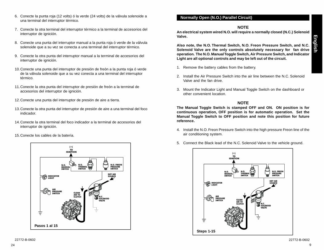
Normally Open (N.O.) Parallel Circuit)
NOTEAn electrical system wired N.O. will require a normally closed (N.C.) SolenoidValve.
Also note, the N.O. Thermal Switch, N.O. Freon Pressure Switch, and N.C.Solenoid Valve are the only controls absolutely necessary for fan driveoperation. The N.O. Manual Toggle Switch, Air Pressure Switch, and IndicatorLight are all optional controls and may be left out of the circuit.
1. Remove the battery cables from the battery.
2. Install the Air Pressure Switch into the air line between the N.C. SolenoidValve and the fan drive.
3. Mount the Indicator Light and Manual Toggle Switch on the dashboard orother convenient location.
NOTEThe Manual Toggle Switch is stamped OFF and ON. ON position is forcontinuous operation, OFF position is for automatic operation. Set theManual Toggle Switch to OFF position and note this position for futurereference.
4. Install the N.O. Freon Pressure Switch into the high pressure Freon line of theair conditioning system.
5. Connect the Black lead of the N.C. Solenoid Valve to the vehicle ground.
Steps 1-15
24
22772-B-0602 22772-B-0602
6. Conecte la punta roja (12 volts) ó la verde (24 volts) de la válvula solenoide auna terminal del interruptor térmico.
7. Conecte la otra terminal del interruptor térmico a la terminal de accesorios delinterruptor de ignición.
8. Conecte una punta del interruptor manual a la punta roja ó verde de la válvulasolenoide que a su vez se conecta a una terminal del interruptor térmico.
9. Conecte la otra punta del interruptor manual a la terminal de accesorios delinterruptor de ignición.
10.Conecte una punta del interruptor de presión de freón a la punta roja ó verdede la válvula solenoide que a su vez conecta a una terminal del interruptortérmico.
11.Conecte la otra punta del interruptor de presión de freón a la terminal deaccesorios del interruptor de ignición.
12.Conecte una punta del interruptor de presión de aire a tierra.
13.Conecte la otra punta del interruptor de presión de aire a una terminal del focoindicador.
14.Conecte la otra terminal del foco indicador a la terminal de accesorios delinterruptor de ignición.
15.Conecte los cables de la batería.
Pasos 1 al 15

10
22772-B-0602 22772-B-0602
6. Connect the Red (12 Volt) or Green (24 Volt) lead of the N.C. Solenoid Valveto one terminal of the N.O. Thermal Switch.
7. Connect the other terminal of the N.O. Thermal Switch to the vehicle accessoryor ignition terminal.
8. Connect one lead of the Manual Toggle Switch to the Red (12 Volt) or Green(24 Volt) lead connecting the N.C. Solenoid Valve to the terminal of the N.O.Thermal Switch.
9. Connect the other lead of the Manual Toggle Switch to the vehicle accessoryor ignition terminal.
10. Connect one lead of the N.O. Freon Pressure Switch to the Red (12 Volt) orGreen (24 Volt) lead connecting the N.C. Solenoid Valve to the terminal of theN.O. Thermal Switch.
11. Connect the other lead of the N.O. Freon Pressure Switch to the vehicleaccessory or ignition terminal.
12. Connect one lead of the Air Pressure Switch to the vehicle ground.
13. Connect the other lead of the Air Pressure Switch to one terminal of theIndicator Light.
14. Connect the other terminal of the Indicator Light to the vehicle accessory orignition terminal.
15. Connect the battery cables to the battery.
Steps 1-15
23
Esp
año
l
Circuito Paralelo Normalmente Abierto N.O.
NOTAUn sistema de alambrado N.O. requiere de una válvula solenoide N.C.Tome en cuenta que el interruptor térmico N.O. el interruptor de presión defreón N.O. y la válvula solenoide N.C. son los únicos controles absolutamentenecesarios para la operación del fan drive. El interruptor manual N.O., elinterruptor de presión y el foco indicador son opcionales y pueden omitirse.
1. Desconecte los cables de la batería.
2. Instale el interruptor de presión de aire en la línea de aire entre el fan drive yla válvula solenoide.
3. Monte el foco indicador y el interruptor manual en el tablero.
NOTAEl interruptor manual está marcado con OFF y ON, la posición ON es paraoperación contínua, la posición OFF es para operación automática. Colóqueloen la posición OFF y anote esta posición para futuras referencias.
4. Instale el interruptor de presión en la línea de alta presión de freón del sistemade aire acondicionado.
5. Conecte la punta negra de la válvula solenoide a tierra.
Pasos 1 al quince

11
En
glish
Electrical System Operation Check
1. With the engine temperature below the Thermal Switch setting, turn on theignition and build up air pressure.
2. Install a jumper wire between the terminals of the N.O. Thermal Switch, this willengage the fan driv e.
Keep hands and tools clear of the fan blades. The fan drive can engage withoutwarning.
3. Remove the jumper wire to exhaust the air and disengage the fan drive.
4. Repeat Steps 1-3 for the N.O. Freon Pressure Switch.
5. Set the Manual Toggle Switch to ON. This will engage the fan drive. TheIndicator Light will light when the Fan Clutch is engaged. If the Indicator Lightfails to light, check the bulb and the Indicator Light’s ground connection.
NOTEOFF position is for automatic operation, ON position is for continuousoperation.
Steps 1-5
22
22772-B-0602 22772-B-0602
Pasos 1 al 5
Verificación de operación del sistema eléctrico
1. Con la temperatura del motor debajo de la temperatura del interruptor térmico,arranque el motor para incrementar la presión de aire.
2. Desconecte una terminal del interruptor térmico, esto hará que se embrague elfan drive.
Mantenga sus manos y herramientas fuera del alcance del ventilador, éstepuede operar en cualquier momento.
3. Reconecte la terminal al interruptor térmico, esto dejará escapar el aire y sedesembragará el fan drive.
4. Repita los pasos 1 a 3 para el interruptor de freón.
5. Coloque el interruptor manual en la posición OFF esto hará que el fan driveembrague, el foco indicador encenderá indicando que el fan drive estáembragado. Si el foco indicador no enciende, verifique que no esté fundido yque no hay falso contacto.
NOTALa posición ON es para operación automática, la posición OFF es paraoperación contínua.

12
22772-B-0602 22772-B-0602
PREVENTIVE MAINTENANCE
1. Before performing work on the fan drive, be sure to follow good shop safetypractices and turn the vehicle ignition off, apply the vehicle's parking brake,and block the vehicle's wheels.
2. Before doing work in the area of the fan:
• Start the vehicle’s engine and build air pressure in excess of 90 PSI.
• Manually engage the fan drive. Observe the fan and fan drive from adistance, look for vibration, fan blade contact, fan drive slippage, and fan
drive operation.
• Turn engine off.
Every 25,000 Miles
Fan and Fan Belt
1. Check the fan for looseness and damage, such as bent, cracked or missingblades, loose rivets or missing weights. Retorque if loose. Replace if damaged.
2. Check for adequate clearance between the fan and the fan shroud or other enginecompartment components. Repair if the clearance is inadequate.
Friction Facing
1. Check for wear condition. Replace when worn to 1/16” thick, oil spotted, or ifburn marks are visible.
EMERGENCY OPERATION
Horton fan drives are designed to permit continued operation in the event of a fandrive air source or electrical control system malfunction.
In the event of a malfunction, torque the two Set Screws to 6 Ft. Lbs. [8.1 N•m] tomanually engage fan drive.
The above procedure is only a temporary solution, the problem must be correctedas soon as possible.
SetScrews
21
Esp
año
l
5. Conecte la punta negra de la válvula solenoide N.O. a tierra.
6. Conecte la punta roja (12 volts) ó la verde (24 volts) de la válvula solenoide auna de las puntas del interruptor de freón.
7. Conecte la otra punta del interruptor de freón a una de las terminales delinterruptor térmico.
8. Conecte la otra terminal del interruptor térmico a una punta del interruptormanual.
9. Conecte la otra punta del interruptor manual a la terminal de accesorios delinterruptor de ignición.
10.Conecte una terminal del interruptor de presión de aire a la tierra.
11.Conecte la otra terminal del interruptor de presión de aire al foco indicador.
12.Conecte la otra terminal del foco indicador a la terminal de accesorios delinterruptor de ignición.
13.Conecte los cables de la batería.
Pasos 1 al 13
13
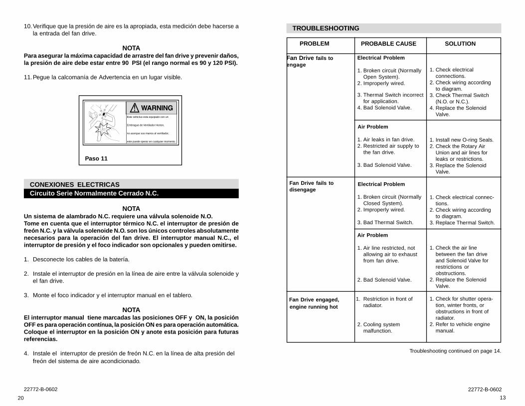
TROUBLESHOOTING
PROBABLE CAUSE
Electrical Problem
1. Broken circuit (NormallyOpen System).
2. Improperly wired.
3. Thermal Switch incorrectfor application.
4. Bad Solenoid Valve.
Air Problem
1. Air leaks in fan drive.2. Restricted air supply to
the fan drive.
3. Bad Solenoid Valve.
Electrical Problem
1. Broken circuit (NormallyClosed System).
2. Improperly wired.
3. Bad Thermal Switch.
Air Problem
1. Air line restricted, notallowing air to exhaustfrom fan drive.
2. Bad Solenoid Valve.
1. Restriction in front ofradiator.
2. Cooling systemmalfunction.
PROBLEM
Fan Drive fails toengage
Fan Drive fails todisengage
Fan Drive engaged, engine running hot
SOLUTION
1. Check electricalconnections.
2. Check wiring accordingto diagram.
3. Check Thermal Switch(N.O. or N.C.).
4. Replace the SolenoidValve.
1. Install new O-ring Seals.2. Check the Rotary Air
Union and air lines forleaks or restrictions.
3. Replace the SolenoidValve.
1. Check electrical connec-tions.
2. Check wiring accordingto diagram.
3. Replace Thermal Switch.
1. Check the air linebetween the fan driveand Solenoid Valve forrestrictions orobstructions.
2. Replace the SolenoidValve.
1. Check for shutter opera-tion, winter fronts, orobstructions in front ofradiator.
2. Refer to vehicle enginemanual.
Troubleshooting continued on page 14.
20
22772-B-0602 22772-B-0602
10.Verifique que la presión de aire es la apropiada, esta medición debe hacerse ala entrada del fan drive.
NOTAPara asegurar la máxima capacidad de arrastre del fan drive y prevenir daños,la presión de aire debe estar entre 90 PSI (el rango normal es 90 y 120 PSI).
11.Pegue la calcomanía de Advertencia en un lugar visible.
Paso 11
CONEXIONES ELECTRICASCircuito Serie Normalmente Cerrado N.C.
NOTAUn sistema de alambrado N.C. requiere una válvula solenoide N.O.Tome en cuenta que el interruptor térmico N.C. el interruptor de presión defreón N.C. y la válvula solenoide N.O. son los únicos controles absolutamentenecesarios para la operación del fan drive. El interruptor manual N.C., elinterruptor de presión y el foco indicador son opcionales y pueden omitirse.
1. Desconecte los cables de la batería.
2. Instale el interruptor de presión en la línea de aire entre la válvula solenoide yel fan drive.
3. Monte el foco indicador y el interruptor manual en el tablero.
NOTAEl interruptor manual tiene marcadas las posiciones OFF y ON, la posiciónOFF es para operación contínua, la posición ON es para operación automática.Coloque el interruptor en la posición ON y anote esta posición para futurasreferencias.
4. Instale el interruptor de presión de freón N.C. en la línea de alta presión delfreón del sistema de aire acondicionado.
Este vehicluo esta equipado con un
Embrague de Ventilador Horton,
no acerque sus manos al ventilador,
este puede operar en cualquier momento.

14
22772-B-0602 22772-B-0602
En
glish
PROBABLE CAUSE
Electrical Problem
1. Poor ground wireconnection.
2. Improper temperaturecontrol settings.
3. A/C Pressure Switchsetting too low.
4. Restriction in front ofradiator, blocking air flow.
5. Faulty Thermal Switch.
6. Faulty Air-Temp Switch.
Air Problem
1. Air line restricted, notallowing air to bereleased from the fandrive.
2. Solenoid Valve notexhausting.
PROBLEM
Fan Drive engaged, engine running hot
(continued)
Fan Drive cycles frequently
SOLUTION
1. Check electricalconnections.
2. Check temperaturesetting of all controls.Thermal Switch settingshould engage the fandrive 10o F higher thanthe full open temperatureof the thermostat.
3. Check the A/C PressureSwitch. Use higherswitch.
4. Check for shutteroperation, winter fronts,or obstructions in front ofthe radiator.
5. Replace the ThermalSwitch.
6. Replace the Air-TempSwitch.
1. Check for pinching orplugging of the air linebetween the fan driveand the Solenoid Valve.
2. Check for a pluggedexhaust port on theSolenoid Valve. Clean orreplace the SolenoidValve.
19
Esp
año
l
4. Monte la válvula solenoide en una posición remota y alta como la pared defuego, en un área donde este libre de vibración, polvo y calor.
5. Conecte la manguera de suministro de aire al puerto de entrada de la válvulasolenoide.
El aire del vehículo debe estar limpio, libre de humedad y aceite.
6. Haga un barreno de 13/32” en la tolva e inserte un grommet de hule.
7. Coloque un tubo de ¼” de diámetro a través del grommet y hasta una distanciaaproximada de ½” de la junta rotativa.
8. Inserte la manguera de 1/8” a través del tubo y conéctelo a la entrada de lajunta rotativa. Conecte el otro extremo de la manguera a la válvula solenoide.
9. Asegure el tubo de ¼” de manera que no toque partes calientes o en movimientocon una abrazadera P.
Pasos 4 y 5
Tolva
Embraque deventilador
Juntarotarivade aire
Grommet dehule
Linea de airede 1/8''
Mangueraprotectora
de 1/4''
Abrazaderatipo “P”
Pasos 6 al 9

15
1527
10
8
1228
13
144
3
29
1
9
5
PARTS LIST
5
914
1322
ITEM DESCRIPTION QTY
1 Mounting Bracket Shaft 13 Drive Sleeve (incl. Bearing) 14 Friction Disc 151 Silicone Sleeve 281 Piston (incl. Friction Facing 1
and Sleeve Bearings)91 Compression Springs 2101 O-ring Seal 111 Air Chamber 1
ITEM DESCRIPTION QTY
12 Socket Head Cap Screw 613 Set Screw 2141 Seal Washer 215 Retaining Washer 116 Pan Head Screw 3221 Shoulder Screw (Locking) 227 Rotary Air Union 1
Assembly28 O-ring Seal 1291 Warning Stcker 1
1 Denotes Repair Kit Item.Repair Kit Part No. 994317.
En
glish
22
11
16
18
22772-B-0602 22772-B-0602
1. Utilizando las tuercas y las roldanas de presión, monte el ventilador en el fandrive, y apriete las tuercas a un par de 13.6 NM (10 pies lbs).
2. Utilizando tornillos SAE grado 8 instale el fan drive en la polea del ventilador.Apriete los tornillos de montaje a un par de 33.9 NM (25 pies lbs).
3. Quite el tapón del múltiple de refrigerante e instale el interruptor térmico.
NOTAColoque el interruptor térmico lo mas cerca posible del termostato. ElInterruptor térmico debe enviar la señal de embrague al fan drive al menos10ºF arriba de la temperatura de apertura del termostato.
Pasos 1 y 2
Se surten las tuercasy roldanas
VentiladorEmbraque
deVentilador
Switchtérmico
Paso 3
16
22772-B-0602 22772-B-0602
INTRODUCCIÓN. ............................................................................................... 16Información General ....................................................................................... 16
PRE-INSTALACION ........................................................................................... 17INSTALACIÓN. ................................................................................................... 17
Preparación del Vehículo ................................................................................ 17Instalación del Fan Drive ................................................................................17
CONEXIONES ELECTRICAS ............................................................................20Circuito Serie Normalmente Cerrado N.C. .....................................................20Circuito Paralelo Normalmente Abierto N.O. ................................................23
MANTENIMIENTO PREVENTIVO ......................................................................26Cada 40,000 kilómetros .................................................................................26
OPERACIÓN DE EMERGENCIA .......................................................................26PROBLEMAS Y SOLUCIONES .........................................................................27LISTA DE PARTES .............................................................................................29
INTRODUCCIÓNInformación general
Este manual describe el procedimiento correcto de la instalación del impulsor deventilador. Siguiendo las instrucciones cuidadosamente se obtendrá la operaciónmas segura y libre de problemas.
Horton utiliza los siguientes avisos, para enfatizar posibles problemas de seguridad,los cuales pueden causar serios daños y provee información para prevenir dañosal equipo.
Se utiliza para indicar la presencia de un riesgo que puede causar Dañospersonales e incluso la muerte, o sustanciales daños al equipo si este seignora.
Se utiliza para indicar la presencia de un riesgo que puede causar dañosseveros, o sustanciales daños al equipo si este se ignora.
Se utiliza para indicar la presencia de un riesgo que puede causar dañosmenores, o daños al equipo si este se ignora.
NOTASe utiliza para notificar a la gente información importante acerca de lainstalación, operación o mantenimiento, pero no hay riesgo involucrado.
17
Esp
año
l
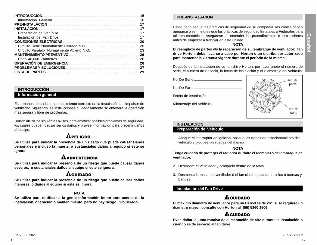
PRE-INSTALACION
Usted debe seguir las prácticas de seguridad de su compañía, las cuales debenapegarse ó ser mejores que las prácticas de seguridad Estatales ó Federales paratalleres mecánicos. Asegúrese de entender los procedimientos e instruccionesantes de empezar a trabajar en esta unidad.
NOTAEl reemplazo de partes y/o la reparación de su (embrague de ventilador) fandrive Horton, debe llevarse a cabo por Horton o un distribuidor autorizadopara mantener la Garantía vigente durante el período de la misma.
Después de la instalación de su fan drive Horton, por favor anote el número deserie, el número de Servicio, la fecha de instalación y el kilometraje del vehículo.
No. De Serie
No. De Parte
Fecha de Instalación
Kilometraje del Vehículo
INSTALACIÓNPreparación del Vehículo
1. Apague el interruptor de ignición, aplique los frenos de estacionamiento delvehículo y bloquee las ruedas del mismo.
NOTATenga cuidado de proteger el radiador durante el reemplazo del embrague deventilador.
2. Desmonte el Ventilador y colóquelo dentro de la tolva
3. Desmonte la masa del ventilador ó el fan clutch quitando tornillos ó tuercas ybandas.
Instalación del Fan Drive
El máximo diámetro de ventilador para un HT650 es de 26”, si se requiere undiámetro mayor, consulte con Horton al (55) 5360 1506
Evite dañar la junta rotativa de alimentación de aire durante la instalación ócuando se dé servicio al fan drive.
No. departe
No. deserie