horn river basin - geoscience bc · pdf filepetrel robertson consulting ltd. ii bh/horn river...
TRANSCRIPT

HORN RIVER BASIN
AQUIFER CHARACTERIZATION
PROJECT
PHASE 2
GEOLOGICAL REPORT
Prepared for:
HORN RIVER BASIN PRODUCERS GROUP GEOSCIENCE B.C.
September, 2011
Petrel Robertson Consulting Ltd. 500, 736 – 8
th Avenue S.W.
Calgary, Alberta T2P 1H4 www.petrelrob.com

Petrel Robertson Consulting Ltd. BH/Horn River Basin Aquifer Project – Phase 2/lps
i
EXECUTIVE SUMMARY
Geoscience BC‟s Phase 1 Horn River Basin Aquifer Characterization Project (PRCL, 2010) concluded that the Mississippian Debolt-Rundle carbonate platform demonstrates the best potential to act as a productive water source and sink for the completions activities of producers in the Horn River Basin. Phase 2 of the study reinforces this conclusion and adds data from new wells drilled since completion of the Phase 1 report. Resulting map revisions increase the overall enhanced reservoir volume, particularly in the centre of the basin, where well control had been sparse. The Debolt-Rundle carbonate platform has been subdivided into four units that are mappable across the basin: the lower, middle and upper Rundle, capped by the Debolt. At the top of the upper Rundle and Debolt, reservoir quality is enhanced by leaching and dolomitization beneath the pre-Cretaceous unconformity, forming a unit referred to as the “Detrital Zone”. The highest-quality and most continuous water-bearing reservoirs thus occur within the upper Rundle and Debolt where they subcrop beneath the pre-Cretaceous unconformity in the eastern part of the Horn River Basin. Reservoir quality mapping was focused on the Debolt-Rundle succession. Net porous reservoir and porosity-thickness maps from the Phase 1 study were updated using sample cuttings observations and well logs from Phase 2 wells. As in Phase 1, approximations regarding reservoir quality had to be applied because of the highly heterogeneous nature of the “Detrital Zone”. These were kept as consistent as possible with the Phase 1 project to ensure continuity. The updates show local increases and decreases in the porosity thickness within the Mississippian detrital zone and the lower enhanced reservoir zone, but there was an overall increase in „confirmed‟ porosity thickness and net porous reservoir. No new fluid and test data were available for the Phase 2 study, but hydrogeological work in the Phase 1 study concluded that more than 10 billion m3 of water is present in the enhanced reservoir portion of Mississippian carbonates, and far greater volumes are present in the lower quality reservoirs. Core and test analyses demonstrate that the good quality reservoirs, in particular in the east of the basin, could support long term high-rate water pumping and injection, but that the regional poorer quality reservoir strata could not support high rates. Data from the Phase 1 study, and from the new Apache/Encana Debolt Water Plant show total dissolved solids within the Debolt-Rundle to be between 15,000 and 40,000 mg/l, and H2S concentrations to be up to 65 mg/L. These values indicate that the water is non-potable, but is suitable for hydraulic fracturing. It should be noted that it was necessary for Apache/Encana to remove the H2S found in the water before use as a hydraulic fracturing fluid.

Petrel Robertson Consulting Ltd. BH/Horn River Basin Aquifer Project – Phase 2/lps
ii
Upper Mississippian Mattson sandstones and basal Cretaceous Gething, Bluesky, and Chinkeh sandstones are considered to have good aquifer potential locally, but their distributions are limited, and test data are scanty. Few wells added for the Phase 2 study contributed significantly to the Phase 1 data already compiled for these units, and therefore, no updates were undertaken for them. The first water production and treatment plant of its kind – the Apache/Encana Debolt Water Plant – is currently producing water from the Debolt aquifer at a rate of 16,000 m3 per day and is predicted to supply at least 90% of the water needs for drilling and completions in the area in 2011 (Waterman, 2011). This plant has provided a successful, economic and environmentally responsible water source, and proves the potential of the Debolt reservoir.

Petrel Robertson Consulting Ltd. BH/Horn River Basin Aquifer Project – Phase 2/lps
iii
TABLE OF CONTENTS
Executive Summary .................................................................................................... i. Table of Contents ........................................................................................................ iii. Illustrations .................................................................................................................. iv. Introduction ................................................................................................................. 1. Study Participants ....................................................................................................... 2. Regional Setting .......................................................................................................... 3. Methodology ................................................................................................................ 9. Geology of Aquifer Wells ............................................................................................. 11. Rundle Group ................................................................................................... 11. Debolt Formation .............................................................................................. 13. “Detrital Zone” ................................................................................................... 13. Mattson Formation and Cretaceous Sandstones.............................................. 14. Reservoir Quality Mapping .......................................................................................... 15. Rundle and Debolt/Detrital Zone ...................................................................... 15. Encana/Apache Debolt water treatment project…………………………………………..19. References ................................................................................................................... 20. Appendix I. Databases (available digitally)
Appendix II. JC Consulting Inc. Report – Drill Cuttings Petrographic Study

Petrel Robertson Consulting Ltd. BH/Horn River Basin Aquifer Project – Phase 2/lps
iv
ILLUSTRATIONS
Map 1. Study area location and index map
Map 2. Structure, basal Cretaceous radioactive marker
Map 3. Depth to pre-Cretaceous unconformity
Map 4. Isopach, pre-Cretaceous unconformity to top Banff
Map 5. Isopach, middle Rundle Group
Map 6. Isopach, upper Rundle Group
Map 7. Isopach, Debolt Formation
Map 8. Isopach, net porous reservoir, Mississippian Detrital Zone
Map 9. Porosity-thickness, Mississippian Detrital Zone
Map 10. Porosity-thickness, Debolt / Rundle enhanced reservoir below Detrital Zone
Map 11. Porosity-thickness, total Mississippian carbonate enhanced reservoir
Figure 1. Schematic stratigraphic cross-section, Horn River Basin and adjacent Liard Basin
Figure 2. Schematic stratigraphic cross-section, showing transition of Mississippian carbonate platform westward and northward to basinal Prophet and Besa River formations (carbonate platform nomenclature from outcrop in Northwest Territories) (from Richards, 1989).
Figure 3. Development of Bovie Fault Zone through time, illustrating structural complexity (from McLean and Morrow, 2004)
Figure 3a. Schematic cross-section across the Liard Basin (from Leckie et al., 1991). Focus is on the Cretaceous section; note that Mississippian through Triassic relationships are not accurately depicted.
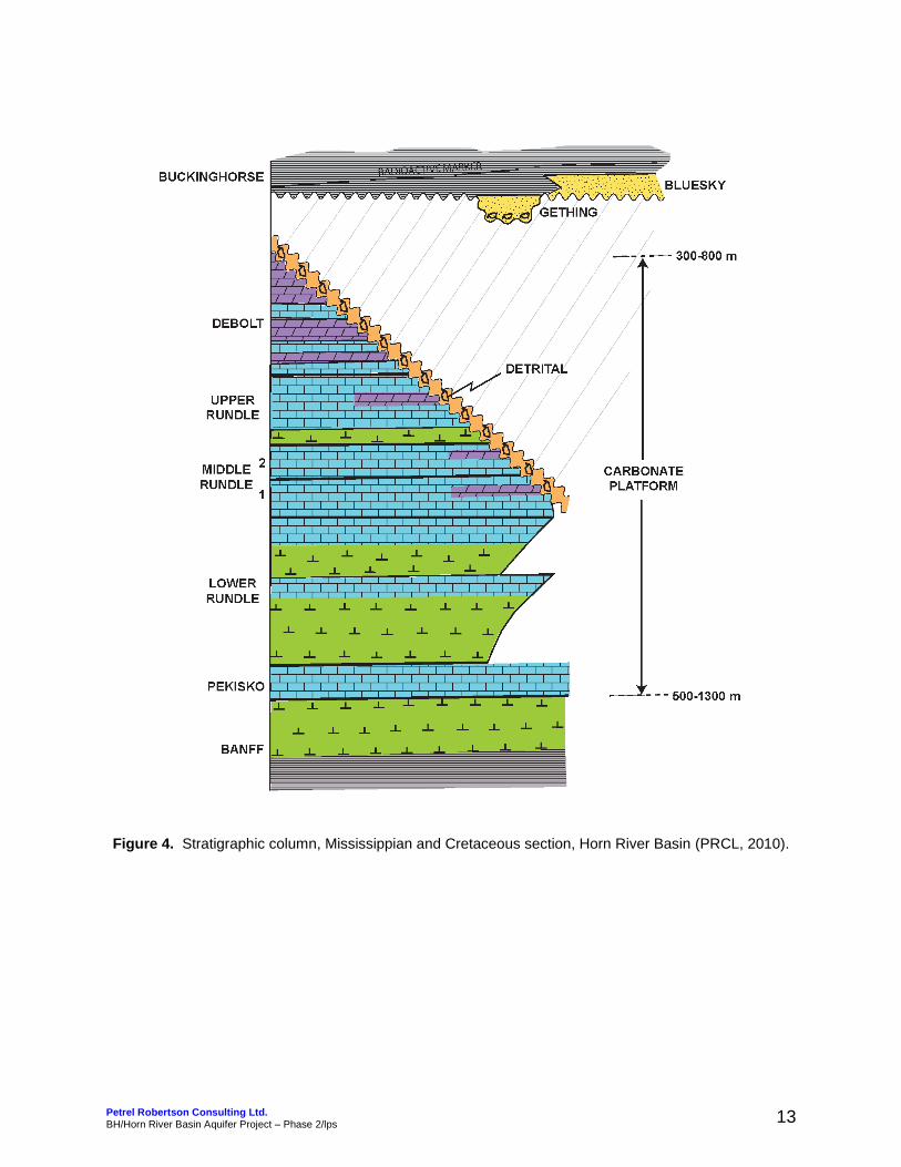
Figure 4. Stratigraphic column, Mississippian and Cretaceous section, Horn River Basin.
Figure RQ1. Density and induction logs for well d-92-H/94-O-9. Note irregular density, neutron, and caliper curves across the “Detrital” zone from 464 to 500 metres.
Regional Cross-Sections
West to east section J-J‟
South to north sections EE-EE‟

Petrel Robertson Consulting Ltd. BH/Horn River Basin Aquifer Project – Phase 2/lps
1
INTRODUCTION
Devonian shales in the Horn River Basin of northeastern British Columbia host one of the largest shale gas plays in North America. Production of this gas requires the drilling of multi-leg horizontal wells, where each leg is stimulated by more than 20 hydraulic fracture stimulation (frac) jobs. Each frac uses up to 4000 m3 of water, which must then be disposed of safely. Deep subsurface aquifers that are found far below both domestic water supplies and the water table are ideal source and disposal sites for this water. The use of non-potable water from deep subsurface aquifers has the potential to drastically reduce the environmental footprint of shale gas development, and to protect fresh water surface aquifers. The huge demand for both water sources and sinks has made the identification and characterization of subsurface aquifers a top priority for those looking to develop the shale gas resource in the Horn River Basin. In October, 2008, in response to requests by the Horn River Basin Producers Group (HRBPG, an assembly of 11 major producers within the basin), Geoscience BC announced a $5 million program to evaluate aquifers within the Horn River Basin. This study, the Horn River Basin Subsurface Aquifer Project (Petrel Robertson Consulting Ltd., 2010), successfully identified and characterized key deep subsurface saline aquifers within the basin; however, it was limited by poor well control in much of the central portion of the basin. In 2011, Geoscience BC arranged funding for a second phase of the original subsurface aquifer characterization project. The target of the Phase 2 study is the Mississippian Debolt / Rundle carbonate platform, which comprises the most extensive and highest quality aquifer. Further development of Horn River Basin gas resources has provided increased well control in previously unconstrained areas of the basin. Where information was available, it was incorporated into the study of the secondary aquifers, such as the basal Cretaceous sandstones and Mattson Formation. Members of the HRBPG were asked to submit any new data not included in the Phase 1 study, including full well log suites, drill cuttings and core across the Cretaceous and Mississippian sections to the base of the Banff Formation. They were also asked to submit any data and results from the testing of shallow aquifers. These data, in addition to that which is publicly available, have been incorporated into a Phase 2 study on the aquifers within the Horn River basin, the results of which are presented in this report.

Petrel Robertson Consulting Ltd. BH/Horn River Basin Aquifer Project – Phase 2/lps
2
STUDY PARTICIPANTS
GEOSCIENCE B.C. is an industry-led, not for profit, applied geoscience organization. They work in collaboration with industry, academia, government, First Nations, and communities to fund projects that will help attract and develop mineral and oil & gas exploration in British Columbia. In 2008 they initiated and managed Phase 1 of the Horn River Basin Aquifer Characterization Project, supported by a targeted grant from the Province of British Columbia. For this Phase 2 project, Geoscience BC has provided additional funding from its own resources, as well as arranging funding from industry participants. The HORN RIVER BASIN PRODUCERS GROUP (HRBPG) is a group of representatives from eleven companies with leases in the Horn River Basin. This group includes Apache, ConocoPhillips, Devon, EnCana, EOG, Imperial Oil, Nexen, Pengrowth, Suncor, Quicksilver and Stone Mountain. Their goal is the responsible development of gas reservoirs in the Horn River Basin. They collectively work to achieve this goal by activities such as minimizing the cumulative environmental impact by multi-well pad drilling, and sharing common infrastructure such as roads, pipe lines and water. They work with First Nations, government and communities to address environmental, social and economic impacts and issues. For both Phase 1 and 2 of the Horn River Basin Aquifer Characterization Project, the HRBPG provided confidential data, including well test data, digital well logs, and drill cuttings. PETREL ROBERTSON CONSULTING LTD. (PRCL) is Canada‟s leading petroleum geoscience and exploration consultancy. They lead projects that range in scale from regional exploration assessments to local reservoir characterization and mapping. PRCL managed both the Phase 1 and 2 Horn River Basin projects, and completed the geoscience work. JC CONSULTING INC. undertakes core and cuttings evaluation for land sale evaluations, exploration, and regional play generation. They evaluate reservoirs for post-drill analysis and formation damage, and specialize in visual permeability estimation from drill cuttings. JC Consulting evaluated and described drill cuttings from 14 wells as part of the Phase 2 project and 63 wells for the Phase 1 project.

Petrel Robertson Consulting Ltd. BH/Horn River Basin Aquifer Project – Phase 2/lps
3
REGIONAL SETTING
This section is taken from the original Horn River Basin Aquifer Characterization Project report (PRCL, 2010). The Horn River Basin (HRB) lies in northeastern British Columbia, and is bounded to the east and south by Devonian carbonate platforms of the Keg River, Sulphur Point, and Slave Point Formations (Map 1). To the west, a major structural feature – the Bovie Fault Zone – separates the HRB from the Liard Basin to the west. The Horn River Basin continues northward into the Northwest Territories, but land, infrastructure, and regulatory issues confine oil and gas activity to the B.C. portion. A structure map of the basal Cretaceous radioactive marker shows a fairly uniform north-northeasterly dip in the eastern half of the basin (Map 2). A closed structural high appears in the southwest, and a closed low in the west to northwest, but these are based on low well control. A high level of structural complexity is evident in the Bovie Fault Zone, and structural elevations are much lower in the Liard Basin to the west (see discussion below). Map 3 illustrates drill depth to the pre-Cretaceous unconformity, which is the level where most aquifer potential is found. Shale gas targets of the HRB occur in the siliceous, organic-rich Evie and Muskwa shale members of the Middle to Upper Devonian Horn River Formation. Westward and northward of the Slave Point / Sulphur Point / Keg River carbonate platform margins, the Horn River Formation forms the basal part of a thick Mississippian – Devonian shale section (Fig. 1). Stacked carbonate ramps/platforms of the Mississippian Rundle Group and Debolt Formation prograde across the Horn River Basin, passing basinward into the Prophet and Besa River formations to the west and north (Richards, 1989; Richards et al., 1993) (Fig. 2). Cretaceous Buckinghorse shales lie unconformably on the Mississippian carbonates, except on the southern and eastern margins of the Basin, where basal Cretaceous sandstones are assigned to the Bluesky and Gething formations, respectively. Quaternary glacial deposits up to 100-150 metres thick cap the Buckinghorse and Upper Cretaceous Dunvegan sandstones and conglomerates, which are preserved locally (Fig. 1). Westward across the Bovie Fault Zone, the top of the Mississippian carbonate ramp drops approximately 1000 metres, and the overlying section thickens correspondingly (Fig. 2; Maps 2, 3). The structural history of the Bovie Fault Zone is complex, as interpreted by McLean and Morrow (2004), so that accurate correlations and mapping require seismic support (e.g., Fig. 3). The uppermost Mississippian Mattson Formation, a sand-dominated deltaic succession, lies on the carbonate platform above

Petrel Robertson Consulting Ltd. BH/Horn River Basin Aquifer Project – Phase 2/lps
4
transgressive Golata shales, and thickens rapidly westward from the BFZ to several hundred metres. Cherts and sandstones of the Permian Fantasque Formation cap an unconformity overlying the Mattson. The Triassic Toad and Grayling formations are primarily siltstone and shale equivalents to the Montney of the Peace River area.

Petrel Robertson Consulting Ltd. BH/Horn River Basin Aquifer Project – Phase 2/lps
5
Figure 1. Schematic stratigraphic cross-section, Horn River Basin and adjacent Liard Basin (From PRCL, 2010).

Petrel Robertson Consulting Ltd. BH/Horn River Basin Aquifer Project – Phase 2/lps
6
Figure 2. Schematic stratigraphic cross-section, showing transition of Mississippian carbonate platform westward and northward to basinal Prophet and Besa River formations (carbonate platform nomenclature from outcrop in Northwest Territories) (from Richards, 1989).

Petrel Robertson Consulting Ltd. BH/Horn River Basin Aquifer Project – Phase 2/lps
7
Figure 3. Development of Bovie Fault Zone through time, illustrating structural complexity (from McLean and Morrow, 2004).
Early Carboniferous: There is neither evidence of Bovie Structure nor Liard Basin on this figure generated by flattening the seismic section on the top of Banff Formation
reflection.
Early Cretaceous: Flattening on the base-Cretaceous unconformity reveals the first phase of Bovie Structure identifiable within the Central zone. The eastern flank of Liard Basin is defined by the abrupt change in Mattson Formation thickness caused by differential erosion across Bovie Fault. Uplift occurred pre-Cretaceous but post-Mattson, possibly coincident with uplift of the nearby
Celibeta High.
Late? Cretaceous: Bovie Fault has been reactivated, possibly as a consequence of stresses imposed during the earliest Laramide. The dashed line marks the yet to be established shallow décollement Bovie Lake Thrust.
Laramide Orogeny: Bovie Lake Thrust has been established as a shallow décollement in the upper Banff Formation and has ‘decapitated’ the hanging-wall block of Bovie Fault. Horizontal translation of about 1.3 km, combined with reactivation of the decapitated portion of the older thrust, has produced today’s subsurface and
surface configurations.

Petrel Robertson Consulting Ltd. BH/Horn River Basin Aquifer Project – Phase 2/lps
8
Overlying the pre-Cretaceous unconformity is the basal Chinkeh sandstone, succeeded by Cretaceous shales, themselves punctuated by widespread, generally low-quality sandstones of the Scatter and Sikanni formations (Fig. 3a). The focus of this report will be on the Debolt/Rundle carbonate ramp/platform, which is the principal aquifer unit within the Horn River Basin. The basal Cretaceous sandstones and the Mattson Formation, which provide more local aquifer capacity were addressed in detail in the Phase 1 report. They will be touched on only briefly in this report.

Petrel Robertson Consulting Ltd. BH/Horn River Basin Aquifer Project – Phase 2/lps
9
Figure 3a. Schematic cross-section across the Liard Basin (from Leckie et al., 1991). Focus is on the Cretaceous section; note that Mississippian through Triassic relationships are not accurately depicted.
Petrel Robertson Consulting Ltd. BH/Horn River Basin Aquifer Project – Phase 2/lps
10
METHODOLOGY
As part of Phase 1 of the Horn River Basin Aquifer Characterization project, well logs, cores, sample cuttings and well test data were incorporated to create stratigraphic maps and develop reservoir characterizations. This original study included a total of 556 wells. Phase 2 adds 272 wells; at the time this report was written, 19 of these wells were on confidential status, and their data were contributed by members of the Horn River Basin Producers Group (HRBPG). The stratigraphic database includes all wells within the study area that penetrate the pre-Cretaceous unconformity. The majority of the wells in the southeast that were drilled to target Jean Marie gas were not logged across the area of interest, and have been excluded. Wells within the Northwest Territories were also excluded from Phase 2 of the study. In order to ensure consistency when picking stratigraphic tops for Phase 2, correlations were made through a series of cross-sections between the Phase 1 and 2 wells. The correlations and picking of units were based on previous studies, literature, and sample cuttings descriptions. Two of these cross-sections have been included as a supplement to the original 16 presented in the Phase 1 report. The stratigraphic tops are also included in a master database (Appendix I). During the original study, cores were logged from 60 wells and provided valuable stratigraphic and reservoir information. Since the Phase 1 study, there has been no additional coring within the interval of interest. In the absence of core, the analysis of drill cuttings has again been used to provide a description of the rock and a semi-quantitative estimate of porosity and permeability. This work was completed by John Clow (JC Consulting), and is described in more detail in Appendix II. Fourteen (14) wells were selected for cuttings descriptions; samples from 11 of these wells were provided by members of the HRBPG. They were selected based on availability, distribution, and proximity to areas with poor sample or well control. Analyses and descriptions were confined to the Cretaceous and Mississippian section (to the base of the Banff Formation), which hosts the best potential reservoirs. As part of the original study, SEM imaging and XRD analyses was performed. This contributed greatly to our current understanding of the prospective reservoirs, but additional work was not determined to be necessary for Phase 2. Canadian Discovery Ltd. compiled well test data for the Phase 1 study to provide maps showing hydraulic head, pressure vs depth, available head, formation water chemistry, H2S chemistry, and resource volumes. Limited public and proprietary well test data was available for the Phase 2 study and as a result, the Phase 1 hydrogeology maps were not revised.

Petrel Robertson Consulting Ltd. BH/Horn River Basin Aquifer Project – Phase 2/lps
11
Phase 2 deliverables include a series of regional maps produced by PRCL. They have been updated from the Phase 1 report to reflect all currently-available data. Important stratigraphic surfaces and intervals associated with the aquifers were mapped and tied with sample data. Estimates of porosity and permeability from samples and logs were incorporated to create reservoir quality maps over the entire study area.

Petrel Robertson Consulting Ltd. BH/Horn River Basin Aquifer Project – Phase 2/lps
12
GEOLOGY OF AQUIFER UNITS
Thorough descriptions and background information on of all the units that were mapped and examined are available in the Phase 1 report (PRCL, 2010). For Phase 2, the focus has been on updating and revising maps on the units that were found in Phase 1 to have the best aquifer potential. Figure 4 shows the stratigraphic relationships of the units that were mapped. Overall, there have been very few revisions made in the far east and south of the study area, where abundant well control provides a confident depiction of the structure. The most notable changes occur within the central basin east of the Bovie Fault system, where several new wells have been drilled in a sparsely-controlled area.
Rundle Group The Rundle Group is found conformably overlying the Pekisko and underlying the Debolt, and comprises the lower portion of the Mississippian carbonate/ramp succession. The Shunda and Elkton subdivisions further south in the Western Canada Sedimentary Basin, as well as stratigraphic units recognized to the north within the Yukon and NWT, cannot be correlated into the Horn River Basin with confidence. We therefore used log markers to subdivide the Rundle into upper, middle and lower units in the Horn River Basin. On a regional scale, the Rundle Group consists of stacked transgressive / regressive cycles that were deposited in an outer ramp through marine shelf to intertidal environments. These cycles prograde northward and westward into the Besa River shale basin (Richards et al., 1994; Richards, 1989; PCRL, 2000; PCRL, 2010). The upper, middle and lower log markers are picked at what are thought to be transgressive surfaces that mark the top of shoaling-upwards cycles. The Rundle succession appears to become cleaner and more proximal upward, with the upper Rundle hosting cleaner carbonates that show less evidence of pronounced shaly transgressive surfaces (PCRL, 2010). The lower Rundle generally does not exhibit good reservoir characteristics and was not mapped separately. Middle Rundle strata are 30-40 m thick throughout the majority of the basin, with restricted areas that are just over 50 m thick in the northwest (Map 5). Pre-Cretaceous erosion cuts the unit to the east to a subcrop edge east of the study area. Revisions to the mapping of the middle Rundle as part of Phase 2 study did little to change its overall appearance. The thickest strata in the northwest appear to be somewhat more aerially restricted and less continuous than originally mapped. Additional well control has also added more constraints to the contours within the central basin, and better defines the relief and the gradual thinning of the unit to the south.
Petrel Robertson Consulting Ltd. BH/Horn River Basin Aquifer Project – Phase 2/lps
13
Figure 4. Stratigraphic column, Mississippian and Cretaceous section, Horn River Basin (PRCL, 2010).
Petrel Robertson Consulting Ltd. BH/Horn River Basin Aquifer Project – Phase 2/lps
14
The upper Rundle is more affected by pre-Cretaceous erosion within the HRB, thinning from just over 100 m to a zero (subcrop) edge in the northeast (Map 6). Erosion is most evident along the eastern edge, beneath a major north-trending pre-Cretaceous valley system. The upper Rundle isopach map shows the greatest overall change in appearance as a result of the additional Phase 2 well control. The isopach is thickest in the north-west corner, it rapidly thins to the east and west, and gradually thins to the south (Map 6).
Debolt Formation
Within the Horn River Basin, the term “Debolt” is commonly used to refer to the entire Mississippian carbonate ramp/platform, but here, we use the term to refer to the clean carbonate that conformably overlays the extensive flooding surface capping the upper Rundle. The Debolt is interpreted to have been deposited in the same progradational carbonate ramp/platform setting as the Rundle Group (PRCL, 2000). Cores from the southwestern part of the study area, taken immediately beneath the pre-Cretaceous unconformity, consist of fractured and rubbled dolomudstones and wackestones, with poor core recovery (PRCL, 2010). Sample cuttings show a range of lithologies from limestone to carbonate mudstones through much of the Debolt, which exhibit poor porosity with isolated moderately porous clean limestones. Much better porosity and permeability are developed in dolomitized sections directly underlying the pre-Cretaceous unconformity and along the eastern subcrop edge, referred to as the “Detrital” zone (discussed in more detail below). These results were observed in the Phase 1 study (PRCL, 2010) and confirmed by additional sample work in Phase 2. The Debolt thins eastward beneath the pre-Cretaceous unconformity (Map 7). In the south, this thinning wraps around and trends in a northward direction. In the southwest corner of the study area, the Debolt is grouped with the undifferentiated Rundle, as correlations cannot be made with confidence. There are no major regional changes between the Phase 1 and 2 maps. The greatest differences are in the northwest corner, where the contours in the Phase 2 map wrap more prominently around to the northwest (showing a local thinning to the south-southwest), and in the central portion of the study area, where increased well control has provided more contour definition.
“Detrital” Zone
The “detrital” zone was first described in Phase 1 of this study. It refers to the intensely leached and dolomitized interval that occurs directly below the pre-Cretaceous unconformity within the Debolt and upper Rundle. This zone has been identified from drill cuttings and in limited areas within core. Very finely crystalline to coarse crystalline dolomites exhibit sucrosic texture, and host pinpoint to large vuggy pores with drusy dolomite linings. Leached cherts and evidence of fracturing is also present (PRCL,
Petrel Robertson Consulting Ltd. BH/Horn River Basin Aquifer Project – Phase 2/lps
15
2010). Further descriptions of sample cuttings from Phase 2 wells covering this zone are available in Appendix II. Porosity values within this zone are estimated to be in excess of 10%, and permeability values up to consistently greater than 50 millidarcies. It should be noted that accurate permeability values are difficult to estimate, particularly in the higher ranges. Due to the highly variable nature of the “detrital” zone and the poor hole conditions that tend to be associated with it, well logs across the zone are difficult to interpret. Often the “detrital” zone is identified by an interval of irregular or off scale responses in the appropriate stratigraphic location (Figure RQ1). Basal Cretaceous Sandstones and the Mattson Formation Basal Cretaceous sandstones, including the Gething and Bluesky and the Chinkeh of the Liard Basin, all exhibit good reservoir quality locally; however, they tend to be relatively thin and laterally heterogeneous. Mississippian Mattson sandstones occur in the extreme west of the Horn River Basin, and abruptly thicken westward into the Liard Basin. They exhibit poor to excellent reservoir quality, and could serve as potential aquifers for producers in that area of the basin (PRCL, 2010). Limited data with respect to these strata were added to the database as part of Phase 2. As a result, there was not enough information for significant updates, and these strata are not reviewed in detail in this report.

Petrel Robertson Consulting Ltd. BH/Horn River Basin Aquifer Project – Phase 2/lps
16
RESERVOIR QUALITY MAPPING
In order to maintain consistency between Phase 1 and 2, the same criteria and methods were used to apply reservoir quality cutoffs to map net reservoir thicknesses and quality. These are laid out below from the Phase 1 study. These simple regional cutoffs serve to outline major trends, and allow for comparisons among different areas. They also allow us to relate hydrogeological data to reservoir presence and continuity. Regional cutoffs are less reliable at a local scale, particularly as mineralogical and particle size reservoir controls cannot be fully assessed.
Rundle and Debolt / Detrital Zone
Reservoir quality mapping in Rundle / Debolt carbonates is focused on specific dolomitized intervals within the platform, and in the capping “detrital zone”. Porosity and permeability are too poor in the unaltered carbonates to be worth systematic regional consideration. Highly variable mineralogy, irregular porosity distribution (intercrystalline, vuggy, fracture), and poor hole conditions make quantitative measurement of porosity from logs virtually impossible (Fig. RQ1). In fact, assigning the weathered interval to the “detrital” versus the Gething is difficult in places, even with sample control. Porosity therefore was estimated in a semi-quantitative fashion, based firstly upon reservoir quality interpretations from sample cuttings:
Excellent: highest-grade porosity, with permeabilities consistently > 50 mD;
Good: good porosity, with permeabilities up to 50 mD;
Poor: limited porosity, with permeabilities generally <1 mD. Log responses were calibrated against Clow sample logs to derive as good a relationship as possible between log response and rock quality. Reliability of the reservoir quality assessment was graded according to the available evidence:
Lithology control:
Good core coverage (best) (actually does not occur in the carbonates);
Clow sample log with good sample quality;
Good wellsite sample log;
Poor wellsite sample log;
No lithological control (worst).

Petrel Robertson Consulting Ltd. BH/Horn River Basin Aquifer Project – Phase 2/lps
17
Figure RQ1. Density and induction logs for well d-92-H/94-O-9. Note irregular density, neutron, and caliper curves across the “Detrital” zone from 464 to 500 metres.
RADIOACTIVE MARKER
GETHING
UPPER RUNDLE
Ø 3%
DETRITAL ZONE
BRC HTR et al OOTLA
D-92-H/94-O-9
MIDDLE RUNDLE 2
MIDDLE RUNDLE 1

Petrel Robertson Consulting Ltd. BH/Horn River Basin Aquifer Project – Phase 2/lps
18
Log control:
Full log suite, including carbonate neutron density and PE curves (best);
Neutron density logs without PE;
Sonic log;
E-logs, gamma-neutron, cased hole logs;
No logs or gamma only (worst). Top, base, and net thickness of the dolomitized/enhanced reservoir zone were picked on sample and/or well logs. Reservoir quality codes were assigned as follows:
E1: excellent reservoir, strong lithology and log support;
E2: excellent reservoir, log evaluation only;
G1: good reservoir, strong lithology and log support;
G2: good reservoir, log evaluation only;
P1: poor reservoir, strong lithology and log support;
P2: poor reservoir, log evaluation only;
CA: enhanced reservoir interval confirmed absent;
ID: insufficient data, cannot confirm presence or absence of reservoir. To provide an estimate of porosity-thickness in support of hydrogeological work and reservoir volumetrics, we assigned excellent reservoir a porosity value of 9%, good reservoir 6%, and poor reservoir 3%. Porosity-thickness values were calculated by assigning a reservoir quality level (E, G, P) to the net reservoir interval in each well, and multiplying by the corresponding porosity value. Thus, for example, a well with 40 net metres of excellent quality reservoir would receive a porosity-thickness value of 40 x 0.09 = 3.6. Reservoir quality codes are posted on each map to give an indication of the reliability of each measurement (thus, an E1 value would receive stronger consideration than an E2 value). We then produced the following reservoir quality maps:
Net porous isopach, “detrital zone” enhanced reservoir (Map 8);
Porosity-thickness, “detrital zone” enhanced reservoir (Map 9);
Porosity-thickness, lower porosity zone enhanced reservoir (Map 10);
Porosity-thickness, enhanced reservoir in total Debolt-Rundle interval (Map 11). These maps provide directional (qualitative to semi-quantitative) measurements of reservoir quality and trends.

Petrel Robertson Consulting Ltd. BH/Horn River Basin Aquifer Project – Phase 2/lps
19
Maps 8 and 9 show enhanced reservoir development in the “detrital” zone focused along the eastern and southern margins of the basin. The thickest and highest-quality rock is in eastern 94-O-9 and 94-O-16. To the south, a narrow trend of higher-quality rock trends slightly southwestward through 94-O-8 and 94-O-1. Additional Phase 2 wells help to better define this trend (c-056-E/094-O-08 and b-035-E/094-O-10), although well control is still fairly sparse. Thinner, somewhat lower-grade reservoir is found to the southeast, and patchily distributed along the southern basin margin. Some poor to moderate enhanced reservoir is seen to the west, but even with additional Phase 2 well control there are not enough wells in this area to confidently define trends. As observed in the Phase 1 study; “Detrital” reservoir quality appears to be developed best in upper Rundle and lower Debolt rocks, particularly near the major north-south Gething valley on the eastern flank of the basin. There is an abundance of relatively clean limestone in these intervals, which appears to be most susceptible to dolomitization and reservoir enhancement (PRCL, 2010). Enhanced reservoir zones below the unconformity are more patchily distributed around the basin, with most occurrences controlled by only a small number of wells (Map 10). Additional Phase 2 wells indicate that the enhanced reservoir along the central south-westerly trend may be more extensive than originally mapped in Phase 1. More well control is needed to fully understand the potential of these zones as water sources and sinks. They could have use as secondary zones to the porosity-enhanced overlying “detrital” zone.

Petrel Robertson Consulting Ltd. BH/Horn River Basin Aquifer Project – Phase 2/lps
20
ENCANA/APACHE
DEBOLT WATER TREATMENT PROJECT
In 2007 Apache and Encana formed a 50/50 joint venture partnership to develop shale gas in the Horn River Basin. They viewed an economic, sustainable and environmentally responsible water source as vital to shale gas development in the area. In the spring of 2009 they began pilot tests on the Debolt Formation and in June of 2010 the Debolt Water Plant was fully operational (Map 1). The Debolt Water Treatment Project won them the Canadian Association of Petroleum Producers 2011 Responsible Canadian Energy Environment Performance Award (Waterman, 2011; CAPP, 2011). The Debolt water treatment plant is the first of its kind. It has the capacity to produce about 16,000 cubic metres of water per day (Waterman, 2011). The goal of the plant is to source at least 90% of the water that Encana and Apache use for fracing from the Debolt. On a nearby multi-well pad, over 96% of the water used for completions was from the Debolt plant. This greatly reduced the environmental impact, and saved over $3 million in water supply costs (Graham, 2011). The water produced is highly saline, with total dissolved solids ranging from 15,000 to 40,000 mg/L and has a H2S concentration of 65 mg/L. The gas is removed in the plant, which operates as a closed system that allows for reuse of the water by reinjection back into the Debolt (Waterman, 2011).
Petrel Robertson Consulting Ltd. BH/Horn River Basin Aquifer Project – Phase 2/lps
21
REFERENCES
Canadian Association of Petroleum Producers, 2011. Water Stewardship in Practice – The Debolt Water
Treatment Project, http://www.capp.ca/energySupply/innovationStories/Water/Pages/debolt.aspx (accessed on September 1, 2011).
Graham, Michael, 2011. Encana‟s CEO Discusses Q1 2011 Results – Earnings Call Transcript, http://seekingalpha.com/article/264609-encana-s-ceo-discusses-q1-2011-results-earnings-call-transcript (accessed on September 1, 2011).
Leckie, D.A., D.J. Potocki, and K. Visser, 1991. The Lower Cretaceous Chinkeh Formation: a frontier type play in the Liard Basin of western Canada. Bulletin of the American Association of Petroleum Geologists, v. 75, p. 1324-1352.
MacLean, B.C., and D.W. Morrow, 2004. Bovie Structure: its evolution and regional context. Bulletin of Canadian Petroleum Geology, v. 52, p. 302-324.
Petrel Robertson Consulting Ltd., 2000. Exploration study of Mississippian and Cretaceous strata, Bivouac area, N.E. British Columbia and N.W. Alberta. Non-exclusive report.
Petrel Robertson Consulting Ltd., 2010. Horn River Basin Subsurface Aquifer Project – Phase 1 Data.. Geoscience BC Report 2010-11 http://www.geosciencebc.com/s/2010-011.asp
Richards, B.C., 1989. Uppermost Devonian and Lower Carboniferous stratigraphy, sedimentation, and diagenesis, southwestern District of Mackenzie and southeastern Yukon Territory. Geological Survey of Canada Bulletin 390
Richards, B.C., E.W. Bamber, A.C. Higgins, and J. Utting, 1993. Carboniferous; Subchapter 4E in Sedimentary Cover of the Craton in Canada, D.F. Stott and J.D. Aitken (ed.); Geological Survey of Canada, Geology of Canada, no. 5, p. 202-271.
Richards, B.C., J.E. Barclay, D. Bryan, A. Hartling, C.M. Henderson and R.C. Hinds, 1994. Carboniferous strata of the Western Canada Sedimentary Basin. In: Geological Atlas of the Western Canada Sedimentary Basin, edited by G.D. Mossop and I. Shetsen. Canadian Society of Petroleum Geologists and Alberta Research Council, Calgary, Alberta, p. 221-250.
Waterman, James, (2011, May 27). Debolt Water Plant. Pipeline News North, Industry News, http://www.pipelinenewsnorth.ca/article/20110527/PIPELINE0118/305279988/debolt-water-plant (accessed on September 5, 2011).

Petrel Robertson Consulting Ltd. bh/Horn River Basin Aquifer Project/lps
APPENDIX I
Databases
(on enclosed CD)

Petrel Robertson Consulting Ltd. bh/Horn River Basin Aquifer Project/lps
APPENDIX II
JC Consulting Inc. Report:
Drill Cuttings Petrographic Study

Petrel Robertson Consulting Ltd. bh/Horn River Basin Aquifer Project/lps
HORN RIVER BASIN AQUIFER CHARACTERIZATION PROJECT DRILL CUTTINGS PETROGRAPHIC STUDY
(JC Consulting Inc.)
METHODOLOGY and GENERAL OVERVIEW
As part of Phase 2 of the Horn River Basin Aquifer Characterization Project our primary purpose was to review rock parameters of potential aquifers through examination of drill cuttings for 20 wells drilled within the Basin, in a manner that was consistent with the work we did in Phase 1. Samples were supplied by the current operators drilling in the area, and by the Geological Survey of Canada‟s Core and Sample Division. We were assigned to determine reservoir quality for the purpose of water disposal potential, or as a water source for drilling and completion operations in the shale basin. Primary targets were the Mississippian Mattson clastics, and the Mississippian Debolt and Rundle carbonates. A rock description strip log was created for each well, using WellSight Systems Strip log program. It facilitates plotting a lithology graphic and written description, along with porosity and permeability estimation values, pore visibility, pore reduction components, hydrocarbon staining and grain size. Drillstem test intervals and results can also be shown. Porosity and permeability estimation is based on a variation of the Sneider1 technique, which compares various measured and observed rock parameters of known rock and compares them to unknown rock. No relevant rock cores were available for this project, and so porosity and permeability estimation was based on previously-viewed rock and work experience. Permeability and porosity values are presented in a more direct format providing estimated value ranges in porosity percentages and permeability in millidarcies rather than „type‟ grouping. The parameters used to identify clastic rock quality and estimate porosity and permeability values are: grain identification, size, shape, consolidation based on quantity and type of intergranular components, primary cements and clay constituents. It is more difficult to determine representative porosity and permeability values for carbonate rocks, because of their heterogeneous nature. Rock type and primary components are described, along with texture, pore type, and alterations such as dolomitization , silicification and leaching. Within the Debolt and Rundle, three main rock types were present:
1 Sneider, R.M., Sneider and Meckel Associates, H. R. King, H. E. Hawkes and T. K. Davis, 1981. “Methods for
Detection and Characterization of Reservoir Rock, Deep Basin Gas Area, Western Canada”, SPE 10072.

Petrel Robertson Consulting Ltd. bh/Horn River Basin Aquifer Project/lps
Porous to predominantly non-porous wackestone / packstone
Porous to very porous dolomite and
Porous silicified/solution zones
Limestones consisted of crypto- to microcrystalline and common fine crystalline limestone, with trace to common bioclastic material, comprising primarily crinoids with common coral and bivalves. Fine to coarse crystalline limestone present in a number of wells had very good intercrystalline porosity, ranging from 3-6%, and permeabilities up to 5+ millidarcies. Dolomitized intervals exhibited excellent porosity and permeability, and are present as very finely crystalline to coarse crystalline dolomite, with common sucrosic texture and pin-point to large vugular pores with drusy dolomite lining. Porosity in this facies ranged from 3-6% to as high as 8-10%, with permeabilities of less than a millidarcy in the fine crystalline rock to several Darcies in the vuggy material. In a number of wells, at least one weathered zone was identified, consisting of silicified and commonly argillaceous crinoidal limestone with common very good dissolution porosity and excellent permeability. The Mattson Formation was also investigated and varied greatly in thickness, from non-existent to very thick, and consisting of very fine- to medium-grained sand, with common carbonate cement and common to abundant glauconite and patchy pyrite. Porosity ranges from 6-12% with permeability ranging from 5-100+ mD, decreasing with depth due to increasing pore-occluding cements. Both the Debolt / Rundle and the Mattson have good potential as either water sources or disposal zones. DST information indicates in numerous wells the zones are wet.

Interpreted Drill Cuttings Description 202/a-052-C / 094-P-04/00Formation: Well Name: ECA ECOG HZ GUNNELL
Status/RR: JN MARIE GAS WELL / 2007TD Depth/Fmn: N/A / N/A / Djn marieExamined: AUG-2011 JC Consulting Inc. J Clow, P Geol 403 651-7890File No: 2011-032
Sample Quality: FAIR TO GOOD - INVERT DRLG MUD resulting in oistained spls and abundant white calcium chloride coating samples.
Krad znKblueskyMu rundle
Dept
h
Grain
Con
glv.
crs
crs
med
Size
fine
v.fin
eSi
lt/ex
tfm
icro
xln
Cla
y/cr
ypto
Lithology
PorosityTotal Poros (%)
Poro
sity
Typ
eOi
l Sho
ws
Perm (mD)Visually Estimated Perm
Core/
DST
Geological Descriptions
5757
558
058
559
059
560
060
561
061
562
062
530
20 Estimated Porosity 0
20 Estimated Porosity 0
photo
6-9%
3-6 to com 8%
1-2%
1-2%
1-2%
? LS/DOL STRAT
1-3%
1-2%
photo
1-2 to tr 3%
Visually Estimated Perm0.01 0.1 1 10 100
Visually Estimated Perm0.01 0.1 1 10 100
0.5-1 to pos 5-10 md
0.05-0.5 to pos 0.5-2 mD
<0.02 md
<0.02 mD
<0.02 mD
0.02-0.05 to pos strky 0.1 or 0,2 mD
<0.02 md
<0.02 to strky <0.05 mD mD
Krad zone
SH, dk gy, blky-fissile, tr SLTST.
SH, as abv, mnr CLYST.
K BlueskySS: vf-u f gr to com l med gr ang-sb ang clr & fros OIL STAINED qtz grs, mod-weakly consolidated, fair to goodgrain relief, tr-com GLAUC, com qtz overgths, sl calc, COMMON VIS POR, 5-9% por, 0.5-1 to pos 5-10 md, weak flor, instant yel blooming cut - NOTE: it appears INVERT DRLG MUD USED - effecting flor, appears to be real oil.
SS: l-u vf gr, tr-com f-l med gr ang-sb ang fros qtz grs, com GLAUC, patchy pyrbit, com qtz rr cht, mod-weakly consolidated, sil, sl calc, TR-com VIS POR, 3-6 to com 8% por, 0.05-0.5 to pos 0.5-2 mD.
M Upper RundleLS: crypto-micro & com f xln, com wh CHERT - siliceousLS, mnr xln por, 1-2%, <0.02 md
LS: crypto-micro xln, P POR/PERM.
LS: crypto-micro xln, P POR/PERM.
DOL: com in spl, vf-f xln, dk brn blk, arg/bituminous, tr vis intxln por, 1-3% por, 0.02-0.05 to pos strky 0.1 or 0,2 mD.
LS: abund in spl, com CHERT - silicified LS, crypto-micro xln, p intxln por.
LS: crypto-micro xln, com vf xln with tr vis intxln por, 1-2 to strky 3%, <0.05 md

Interpreted Drill Cuttings Description 200/a-100-B / 094-O-09/00Formation: Well Name: NEXEN INC. TRAIL
Status/RR: N/A / FEB 2011TD Depth/Fmn: PROJ 2700m / Dkeg riverExamined: AUG-2011 JC Consulting Inc. J Clow, P Geol 403 651-7890File No: 2011-032
Sample Quality: good
MISS DEBOLT
Dept
h
Grain
Con
glv.
crs
crs
med
Size
fine
v.fin
eSi
lt/ex
tfm
icro
xln
Cla
y/cr
ypto
Lithology
PorosityTotal Poros (%)
Poro
sity
Typ
eOi
l Sho
ws
Perm (mD)Visually Estimated Perm
Core/
DST
Geological Descriptions
6060
561
061
562
062
563
063
564
064
565
055
20 Estimated Porosity 0
20 Estimated Porosity 0
1-2%
3-4%
1-3% predom micro earthy por
photo
4-6% to pos strky 8%
1-2%
1-2%
1%
1-2%
1-2%
Visually Estimated Perm0.01 0.1 1 10 100
Visually Estimated Perm0.01 0.1 1 10 100
<0.03 md
<0.05 mD ?
<0.03 md
0.1-0.4 to pos 1-2 md
<0.02 mD
<0.02 md
<0.02 md
<0.02 md
SH, dk gy blk, BLKY, fissile.
K RAD ZONE
SH, com ctgs with spekled calcite.
SH, com SLTST.
MISS DEBOLT
CHT, wh-gy fragments, tr weathered white LS, tr vf xln LS with com MICA, weathered sfc; spl is 95% shale.
CHT, weathered, tr DOL: micro xln, gy, tr vf XL, 1-2 or 3% por, <0.05 md; com LS: chalky, com micro xln,
LS: micro-vf xln, abund dk brn OIL STAINED earthy LS, com GOOD INTXLN POR, tr-com PIN POINT VUGGY POR, 4-6% to pos strky 8%, 0.1-0.4 to pos 1-2 md, dk brnoil stain, good yel flor and instant yel-wh fast blooming solvent cut.
LS: micro-f xln, com chalky texture, com f-med xln with v p intxln por, vf-f xln has fair to good intxln por abund chalky weatherd LS.
LS: crypto-micro xln, sl arg, p intxln por, 1%
LS: crypto-micro xln, sl arg, p intxln por, 1%
LS: crypto-micro xln, sl arg, p intxln por, 1%

Interpreted Drill Cuttings Description 200/a-100-J / 094-O-07/00Formation: Well Name: DEVON NEC TATTOO
Status/RR: N/A / FEB 2010TD Depth/Fmn: N/A / Proj 2930m, Dkeg rExamined: AUG-2011 JC Consulting Inc. J Clow, P Geol 403 651-7890File No: 2011-032
Sample Quality: GOOD
MISS DEBOLT
Dept
h
Grain
Con
glv.
crs
crs
med
Size
fine
v.fin
eSi
lt/ex
tfm
icro
xln
Cla
y/cr
ypto
Lithology
PorosityTotal Poros (%)
Poro
sity
Typ
eOi
l Sho
ws
Perm (mD)Visually Estimated Perm
Core/
DST
Geological Descriptions
5758
058
559
059
560
060
561
061
562
062
563
035
20 Estimated Porosity 0
20 Estimated Porosity 0
4-8%
3-6 to pos 8%
1-2%
2-4 TO POS 6%
1-2%
1-2%
1-2%
1-2%
1-2%
Visually Estimated Perm0.01 0.1 1 10 100
Visually Estimated Perm0.01 0.1 1 10 100
1-3 + mD
0.1-0.5 to pos 1 md
<0.02 mD
<0.1 md
<0.05 md
<0.02 md
<0.02 md
<0.02 md
SH, dk gy blk, blky, fissile, tr SLTST.
SH, dk gy blk, blky, fissile, tr SLTST.
Krad zn
LS: earthy brn, crypto-micro xln & arg, com chalky texture, SS: vf gr, ang clr qtzose, sil, GLAUCONITIC, tr-com vis por, 3-6 to pos 8% por, 0.1-0.5 to pos 1 md; tr SIDERITE NODULES.
MdeboltLS: crypto-micro xln, com f-med xln, sl arg, tr disseminated PYR, silty, P POR, tr SS interbeds: vf-f gr with tr carb mat and GLAUC,
LS: lt brn cryptoxln, com interbedded GLAUCONITE-RICH dk gy SH, com CHERT - LT BRN, BEDDED.LS: lt brn OIL stained EARTHY, tr vf-med xln, RARE PIN PINT VUGGY POR, 2-4 TO POS 6% prdom micro/earthy por, <0.1 mD.
LS: earthy with patchy brn OIL stain, com chalky.
LS: tr lt gy micro xln, com arg earthy material, tr CHERT - SILICEOUS FOSSIFEROUS LS; tr-com vf gr glauconitic SS, sil, no vis por;
LS: dk gy, V ARGILLACEOUS, 1-2% por,
LS: dk gy, V ARGILLACEOUS, 1-2% por,
LS: micro to vf xln, dk gy, V ARGILLACEOUS, 1-2% por,
LS: vf xln, dk gy, v argillaceous.
LS: crypto-micro xln, lt brn, dense.

Interpreted Drill Cuttings Description 200/b-035-E / 094-O-10/00Sample Quality: GOODFormation: Well Name: EOG TATTOO
Status/RR: WATER DISPOSAL / 2010TD Depth/Fmn: 1386m MD, 1299m TVD / MdeboltExamined: JUL-2011 JC Consulting Inc. J Clow, P Geol 403 651-7890File No: 2011-032
KmattsonDdebolt
Samples were described to 1055m in the Debolt. Perf'd interval continues to 1250m and was not described.
Dept
h
Grain
Con
glv.
crs
crs
med
Size
fine
v.fin
eSi
lt/ex
tfm
icro
xln
Cla
y/cr
ypto
Lithology
PorosityTotal Poros (%)
Poro
sity
Typ
eOi
l Sho
ws
Perm (mD)Visually Estimated Perm
Core/
DST
Geological Descriptions
9292
593
093
594
094
595
095
596
096
597
097
598
098
599
099
510
00
20 Estimated Porosity 0
20 Estimated Porosity 0
20 Estimated Porosity 0
3-6%
1-2%
1-2%
6-9 or 10% por
1-2%
PHOTO
6-9%
6-9%
1-3%
PHOTOS 7-9%
1-2%
6-9 or 10%
Visually Estimated Perm0.01 0.1 1 10 100
Visually Estimated Perm0.01 0.1 1 10 100
Visually Estimated Perm0.01 0.1 1 10 100
<0.05-0.3 mD
PERF INTERVAL
<0.02 mD
<0.02 md
3-5 mD
<0.02 mD
0.1-0.5 to com 1-3 to pos 5+ mD
0.05-0.5 to pos1-5+ md
<0.02 mD
5-50+ mD
<0.02 mD
1-3 to pos 5-10+ mD
Sampling begins in the Kmattson abovethe log-porous sands.SH, COAL, tr CLAYST, com SS: vf-f gr angular clr qtzose, tr carb grs, com qtz cmt & tr kao clay, GOOD GRN RELIEF, TR VIS POR, 3-6% por, <0.05-0.3 md.
SH, COAL, com SS: vf gr, ang-sb ang qtzose, sil, NO VISPOR.
SS: vf-u f gr, ang-sb ang qtzose, tr carb mat, abund qtz cmt, RR GLAUC, no grain relief NO VIS POR, 1-2% por, <0.02 md.
SH, com SS: vf, vf-f & tr l med gr, ang qtz grs with com overgrths, abund qz cmt, poor grn relief, 1-2% por, <0.02md.
SS: vf-l f gr, ang qtzose, abund qtz overgths and cmt, TR VIS POR, 1-3 to tr 3-6 to tr 6-8 or 9% por, mod-weaklyconsolidated, 0.02-0.05 to com 0.5 md, strky 1-2 md, lt brn OIL stain, no flor or solvent cut, drlg fluid ?
950 SPL; abund sand in spl, vf, vf-l f gr & com f-l med gang qtz grs with com overgrths, tr LOCAL BIT plugging, gen not a problem, COMLY DISSAGG IN SPL, COM EX VISIBLE POR, 3-6 to 9% por, 0.1-0.5 to com 1-3 to pos 5+mD.
SS: vf-l f gr, ang clr qtzose, lt brn oil stain, weakly consol to predom DISSAGG in spl, few consol ctgs with com qtz cmt/overgths, tr kao clay, good grn relief, 6-9% por, 0.05-0.5 to pos 1-5+ md.
SH & COAL, abund dissagg sd cavings.
SH, COAL.
SH, com COAL, com SS: vf, vf-f gr, sil, no vis por.
SH, COAL, abund dissagg qtz gr cavings.
Spls appear to be 5m low to logs.
990SH, SLTST grading to vf gr SS, sil, no vis por.
995 SPL; SH, COAL, abundant SS: vf-l f gr, ang-sb ang qzose, comly dissagg, consol grs with com consol ctgs mod w consolidated with NO VIS POR.
Mdebolt1000 m SPL; ABUND DISSAGG POROUS SS, TR VERY POROUS DOLOMITE: micro-vf xln-sucrosic, FEW CTGS WITH LARGE DOLOMITE XTLS - VOID/VUG LINING, infer 7-9% POR, 5-50+ mD.SS: abund, f-l med gr, ang clr qtzose, v sil, rr GLAUC, no vis por, FEW CTGS WITH GOOD GRN RELIEF AND NO VIS POR.
SS: abundant in spl, vf-u f and tr l med gr ang qtzose, tr PYRBIT, poor to com very GOOD GRAIN RELIEF, com vis por, EX POR/PERM, 6-9 or 10% por, 1-3 to pos 5-10+ mD.
COM DK BRN-BLK OILY MUD ADDITIVE.
1005 SPL; SS: abund in spl, vf-u f gr, ang clr qtzose, com qtz overgrths and cmt com ctgs with good grn

1005
1010
1015
1020
1025
1030
1035
1040
1045
1050
55
20 Estimated Porosity 0
2-3 to com5-9%
1% to com 3-6 and up to 9%
1-2 or 3%
2-3%
3-6%
PHOTO
1-3% to com 3-6%+, 0.05-0.5 to com 1-5 md
PHOTO
1-3 to pos 5%
1-3%
PHOTO
1-3%
Visually Estimated Perm0.01 0.1 1 10 100
<0.03 mD to com 1-5 md
0.1-0.5 to com1-5 md
<0.03 mD
0.1-0.5 to com 1-5 md
PERF INTERVAL
<0.05-0.5 md
<0.05-0.5 md
<0.05 md
com qtz overgrths and cmt, com ctgs with good grnrelief and GOOD VIS POR, 2-3 to com 5-9% por, <0.03 mD to com 1-5 md.
1010 SPL; abund SS as abv, com DOL and com CHERT -silicified LS, DOL: FEW TO COM CTGS, DOL: cryptoxln to com SUCROSIC - com RHOMBS, COM Micro to very fine xln DOL with com intxln and pin vuggy por, comly biuminous, no porosity indicated on logs, 1% to com 3-6and up to 9% por, <0.02 to com 0.1-0.5 to com 1-5 md, very mixed sample, ?? stratigraphic location.
1015 SPL; DOL: mottled lt-dk gy, crypto-micro xln,
DOL: vf-f and l med xln, mottled off wh-lt brn, tr arg mat,tr-com CHERT, 1-2 or 3% intxln por, <0.05 md, com vf xln wit com patchy SUCROSIC texture, com 3-6% por w0.1-0.5 to com 1-5 md; com SS: in spl, vf-u f gr, ang clr qtzose, mod-weakly consol, sil, good grn relief, tr-com PYRBIT, tr vis por, 2-3% por, <0.03 mD.
DOL: micro-vf xln to com vf xln, tr sucrosic, 1-3 to pos 4-5% pos, <0.05-0.5 md.
DOL: micro-predom vf-f xln, off wh to gy to lt brn, sl arg,tr bit, 1-3%, <0.05 md.
DOL: micro-predom vf-f xln, off wh to gy to lt brn, sl arg,tr bit, 1-3%, <0.05 md.
DOL: micro-predom vf-f xln, off wh to gy to lt brn, sl arg,tr bit, 1-3%, <0.05 md.
PERF'D INTERVAL CONTINUES ON TO 1250m, NOT DESCRIBED.
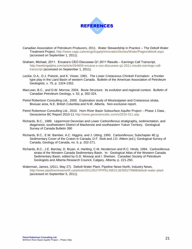
Interpreted Drill Cuttings Description 100/ b-062-C / 094-J-15Formation: Well Name: ALCAN HZ EVIE
Status/RR: SUSP WATER DISP / 2004TD Depth/Fmn: 1300m TVD / Dtrout rvExamined: JUL-2011 JC Consulting Inc. J Clow, P Geol 403 651-7890File No: 2011-032
Sample Quality: GOOD
Krad znMiss DEBOLT
Dept
h
Grain
Con
glv.
crs
crs
med
Size
fine
v.fin
eSi
lt/ex
tfm
icro
xln
Cla
y/cr
ypto
Lithology
PorosityTotal Poros (%)
Poro
sity
Typ
eOi
l Sho
ws
Perm (mD)Visually Estimated Perm
Core/
DST
Geological Descriptions
4950
050
551
051
552
052
553
053
554
054
555
055
556
056
557
057
5
20 Estimated Porosity 0
20 Estimated Porosity 0
1-2%
1-2%
PHOTO3-6 TO POS 8%
EROSIONAL SFCPHOTOS
6-9%+
1-2%
2-3 to 5%PHOTOS
1-2%
1-2%
1-2%
1-2%
1-2%
1-2%
photo3-6%
Visually Estimated Perm0.01 0.1 1 10 100
Visually Estimated Perm0.01 0.1 1 10 100
<0.02 md
<0.02 md
<0.02 TO COM 0.05-0.5 to pos 1-2 md
5-50 mD +
<0.02 md
0.05-0.5 md
<0.02 mD
<0.02 mD
<0.02 md
<0.03 mD
<0.03 mD
<0.03 mD
0.05-0.5 to pso 1-2 md
505 SPL; SH: dk gy brn-brn blk; tr-com CLAYST; TR GLAUC GRS; abund SS: vf-f, com f-u med gr, ang-sb ang trnsluc fros QTZ grs, w cmt'd with QTZ and tr CALCITE, ABUND MICA (Biotite), com PYRITE, NO VIS POR - Krad zn
510 SPL; SH: 95%, mnr SS as descr abv.
ERC top
SS: l vf-l f gr, ang-sb ang mod w sort clr & fros qtz grs, slty, good grain relief, 2-5% GLAUC, tr-com argillaceousmaterial, sil, sl calc, com kao clay, TR-COM VIS POR, 3-6 TO POS 8% POR, <0.02 TO COM 0.05-0.5 to pos 1-2 mD.
SH, lt-med gy, gy brn CLAYSTONE,
MdeboltWeathered sfc, DOL: vf-f xln, med brn, tr BIT, COM INTXLN AND PIN POINT VUGGY POROSITY, 6-9% POR, 5-50 mD +, com microxln lt brn DOl with com attached clr qtz cmt - void-fill, com DOL: cryptoxln, lt brn, v dense
CHT: silicified LS, mottled lt/dk, fossiliferous; LS: mottled lt & dk brn, cryptomicro-xf xln, arg/bituminous, crinoidal wackestone, no vis por, 1-2% intlxn por, <0.02 md.
DOL: micro-l vf xln, sl arg, slty, fair to GOOD INTXLN AND COM PIN POINT VUGGY POR, 2-3 to 5% por, 0.05-0.5 md.
LS: crypto-micro xlh, lt brn, sl arg, slty, NO VIS POR, COM CHERT - silicified LS, 1-2% por, <0.02 md.
LS: crypto-micro xlh, lt brn, sl arg, slty, NO VIS POR, COM CHERT - silicified LS, 1-2% por, <0.02 md.
LS: crypto-micro xln, lt-med brn, sl arg, 1-2% intln por, <0.03 md.
OPEN FRAC - DRUSY CALCITE ON ONE SIDE OF LS CTG
LS: crypto-micro xln, com med xln, lt-med brn, sl arg, tr crinoid, crinoidal wackestone, 1-2% intln por, <0.03 md.
LS: vf-med xln, lt-med brn, 1-2% intlxn por, <0.03 md.
LS: vf-med xln, lt-med brn, 1-2% intlxn por, <0.03 md.
LS: micro-xf xln, tr arg/bit material, COM INTXLN POR, silty, 3-6% por, 0.05-0.5 to pos 1-2 md

580
585
590
595
00
3-5% 0.05-0.5 mD
LS: vf-med xln, p intxln por, <0.02 md
590 spl; abund SH: dk gy brn blk; com f-med xln LS as abv.
LS: micro-vf xln, sl slty, tr bit, FAIR TO GOOD INTXLN POR, 3-5%, <0.05-0.5 mD
HEALED FRAC - com clr xln calcite.
UPPER RUNDLE

Interpreted Drill Cuttings Description 200/b-066-B / 094-O-10/00Formation: Well Name: ECA TATTOO
Status/RR: N/A / MAR2011TD Depth/Fmn: Proj 2746m / Proj Dkeg rExamined: SEP-2011 JC Consulting Inc. J Clow, P Geol 403 651-7890File No: 2011-032
Sample Quality: FAIR, off depth and dirty.
MISS DEBOLT
Dept
h
Grain
Con
glv.
crs
crs
med
Size
fine
v.fin
eSi
lt/ex
tfm
icro
xln
Cla
y/cr
ypto
Lithology
PorosityTotal Poros (%)
Poro
sity
Typ
eOi
l Sho
ws
Perm (mD)Visually Estimated Perm
Core/
DST
Geological Descriptions
6667
067
568
068
569
069
570
070
510
20 Estimated Porosity 0
20 Estimated Porosity 0
3-6 to pos 8%
1-3%
1%
1-3% earthy/chalky
1-3% chalky-earthypor
Visually Estimated Perm0.01 0.1 1 10 100
Visually Estimated Perm0.01 0.1 1 10 100
0.05-0.3 md
<0.05 mD
0.01 md
<0.02 md
<0.02 md
670 SPL; SH: dk gy, gy blk
SAMPLES ARE 5-10m HIGH TO LOG
SS: silt to l vf gr, ang clr qtzose, tr carb mat, com GLAUC, siliceous, TR VIS POR, 3-6 to pos 8% por, 0.05-0.3 md.
M DEBOLT675 SPL; CHT: white-lt brn, bedded, DOL: crypto-micro xln, biege.LS: wh, siliceous weathered - sl porous, sdy with glauconite, 1-2 or 3%, <0.05 md
DOL: crypto-micro xln, sl earthy in part, lt brn, v sl arg, v poor intxln por, 1%
LS: micro-vf xln, com earthy, tr crinoidal wackest, 1-2%, <0.0 2md
LS: chalky-earthy, sl arg, sl-comly fossiliferous.
LS: chalky - earthy, fossiliferous, crinoids, pelecypods.

Interpreted Drill Cuttings Description 200/c-014-G 094-O-09/00Formation: Well Name: EOG HZ TRAIL
Status/RR: POTENTIAL WELLTD Depth/Fmn: 2547m / DmuskwaExamined: JUL-2011 JC Consulting Inc. J Clow, P Geol 403 651-7890File No: 2011-032
Sample Quality: Good
Krad znMdeboltMrundle
Dept
h
Grain
Con
glv.
crs
crs
med
Size
fine
v.fin
eSi
lt/ex
tfm
icro
xln
Cla
y/cr
ypto
Lithology
PorosityTotal Poros (%)
Poro
sity
Typ
eOi
l Sho
ws
Perm (mD)Visually Estimated Perm
Core/
DST
Geological Descriptions
5555
556
056
557
057
558
058
559
059
560
060
561
061
562
062
563
0
20 Estimated Porosity 0
20 Estimated Porosity 0
1-2%
PHOTOS6-9 or 10% por
6-9 or 10% por
1-3%
2-3 to com 4 or5%
2-4%
1-2 or 3%
1-2%
1-2%
photos
3-6 to pos 6-8 or 9%
1-2 to predom 3-6 and 8 or 9%
photos
1-2 to pos tr 3%
Visually Estimated Perm0.01 0.1 1 10 100
Visually Estimated Perm0.01 0.1 1 10 100
<0.02 md
1-5 to 10+ md
1-5 to 10+ md
<0.03 md
<0.5 md
<0.05 mD
<0.05 mD
<0.02 mD
<0.02 mD
0.5-1 to com 1-5 to pos 10+ mD
<0.02 to predom 1-5 to com 10+ mD
<0.02 to pos<0.05 mD
SH; dk gy, gy blk in part, speckled calcite.
Krad znSS: vf-l med gr, ang-sb ang wh translucent qtz, sil, calc, com MICA (biotite), NO VIS POR.
CLAYST: off wh-lt brn.
MdeboltDOL: micro-xf xln, dk brn, arg, com SUCROSIC texture, com intermixed CHERT - weathered sfc, DK BRN OIL STAINED, EXCELLENT POR/PERM, 3-6 to com 9 or 10% por, 1-5 to com 10+ mD, GOLDEN YEL FLOR, INSTANT STREAMING YEL CUT.
DOL: abund as abv (cavings?), com micro-vf xln dk brn oil staining, exc por & perm.
LS: crypto-micro xln, lt brn, chalky in part, 1-2 to pos 3%por, lt brn OIL stained.
LS: vf-f xln, chalky in part, com SANDY INTERBEDS WITH COM GLAUC, vf gr, sil, fair intxln por, 2-3%, OIL STAINED, <0.5 md
LS: vf-f and com med xln, lt brn OIL stained, 1-3% intxln por, <0.05 md, tr-com CHERT - SILICIFIED LS.
LS: micro-xf xln, com vf-f and med xln as abv,
LS: micro-xf xln, off wh-gy, 1-2% micro xln por, sl arg.
SH: dk gy, slty.
U Mrundle
605 spl; LS: crypto-micro xln, lt-dk brn, sl arg, com micro-vf xln, gen p por/perm, 1-2%, <0.02 md.
610 spl; LS: weathered in part, vf-f xln, brn, sl arg, com WEATHERED CHERT - White with com dissolutions por,few ctgs with large drusy calcite on on side - vug lining, com good intxln por, 3-6 to pos 8 or 9% por, 0.5-1 to com 1-5 to pos 10+ mD.
Oil stained, patchy oil stained weathered CHERT, golden yel flor, instant streaming golden yel cut.
LS: com weathered porous patchy OIL stained CHERT, com silicifed LS, com vf & vf-f xln OIL STAINED LS with good intxln por, 1-2 to predom 3-6 and 8 or 9% por, <0.02 to predom 1-5 to com 10+ mD
LS: crypto-microxln, comly siliceous wi intxln and tr pin point vuggy por, tr bit, tr-com CHERT: gy, silicified LS, 1-2 to pos tr 3% intxln por, <0.02 to pos<0.05 mD

35
LS: crypto-micro xln, com chalky texture, tr-com chert (cavings?), 1-2%, <0.02 md.

200/c-015-B / 094-O-16/00Interpreted Drill Cuttings DescriptionFormation: Well Name: DEVON NEC PETITOT
Status/RR: Cased Standing/ Feb 2010TD Depth/Fmn: 2700m / Dkeg riverExamined: AUG-2011 JC Consulting Inc. J Clow, P Geol 403 651-7890File No: 2011-032
Sample Quality: EXCELLENT
MISS DEBOLT
Dept
h
Grain
Con
glv.
crs
crs
med
Size
fine
v.fin
eSi
lt/ex
tfm
icro
xln
Cla
y/cr
ypto
Lithology
PorosityTotal Poros (%)
Poro
sity
Typ
eOi
l Sho
ws
Perm (mD)Visually Estimated Perm
Core/
DST
Geological Descriptions
4040
541
041
542
042
543
043
544
044
545
045
560
20 Estimated Porosity 0
20 Estimated Porosity 0
10-16%photo
WEATHERED SFC
6-10% weathered por
WEATHERED
photos
Weathered LS
12-16%
12-16%
silicifed LS
1-3% to pos 6% earthy por
1-2%
Visually Estimated Perm0.01 0.1 1 10 100
Visually Estimated Perm0.01 0.1 1 10 100
5-50 TO POS 200md +
1-5 mD +
5-50 mD
<0.02 mD
SH: dk gy blk, fissile.
K rad zn
SH: dk gy blk, fissile, blky, sl slty in part.
SS: vf-l med gr, ang-sb ang clr fros qtzose, com overgths and cmt, weakly consolidated - comly dissagg in spl, LT BRN OIL STAIN, exc grn relief, com TRIPOLITIC CHERT, 10-16% POR, 5-50 TO POS 200md +, golden yel flor, instant fast blooming yel solvent cut.
MISS DEBOLT ?
CHERT: wh-dk gy, silicified fossiliferous LS, com chalkyweathered silicifed porous LS, com lt varicol CHT PEBBLES, com weathered dissolution chert with attached SS as descr abv, weathered mixed interval,
CHERT: wh-dk gy, silicified fossiliferous LS, com chalkyweathered silicifed porous LS, com lt varicol CHT PEBBLES,
CHERT: silicified LS & abund SS, pebs, weathered LS asdescribed abv, ABUND SS as descrbed abv, oil stained, exc por/perm.
440 spl is predom DISSAGG SS, OIL STAINED AS ABV, vf-u med gr, ang-sb ang fros qtz with com overgrths, com brkn wh-gy CHERT PEBS OR BEDDED (?), com qtz cmt, exc grn relief, 12-16% POR, 5-50 mD to pos several hundred.
445 spl: abund lt-dk gy, brn CHERT - silicified LS, COM WEATHERED POROUS WEATHERED LS, tr gy-green CLAYSTONE.
LS: vf-med xln with OIL STAINED earthy 'matrix', 2-3% to pos 6% earthy por, com BLK SH.
LS: micro-vf xln, sl arg & bit, p por.

Interpreted Drill Cuttings Description 200/c-044-J / 094-O-07/00Sample Quality: GOODFormation: Well Name: DEVON NEC TATTO
Status/RR: N/A / JAN 2011TD Depth/Fmn: Proj 3005m / Dkeg riverExamined: AUG-2011 JC Consulting Inc. J Clow, P Geol 403 651-7890File No: 2011-032
MISS DEBOLT
Dept
h
Grain
Con
glv.
crs
crs
med
Size
fine
v.fin
eSi
lt/ex
tfm
icro
xln
Cla
y/cr
ypto
Lithology
PorosityTotal Poros (%)
Poro
sity
Typ
eOi
l Sho
ws
Perm (mD)Visually Estimated Perm
Core/
DST
Geological Descriptions
5858
559
059
560
060
561
061
562
062
563
035
20 Estimated Porosity 0
20 Estimated Porosity 0
2-3%
photo3-6 to 8%
1-2%
1-2%
1-2%
Visually Estimated Perm0.01 0.1 1 10 100
Visually Estimated Perm0.01 0.1 1 10 100
<0.03 md
<0.02 to few ctgs with 0.05-0.5 md
<0.02 mD
<0.02 md
<0.02 md
SH, dk gy blk, blocky to fissile, mnr SLTST.
SH: dk gy , blky, fissile, tr SLTST.
Krad zone
Mdebolt
LS: wh, chalky, sil, weatheredLS: micro-vf and vf-f xln, off wh-brn, lt-dk gy, sl arg, sl slty, tr-com CHERT.
CHERT: abund in spl, dk gy blk silicified LS, fossiliferous, com LS: chalky,; SS: few ctgs, vf gr agn clr qtz grs with com qtz cmt, tr-com GLAUC, NO VIS POR to few ctgs with TR VIS POR, 3-6 to tr 8%, <0.02 to few ctgs with 0.05-0.5 md.
CHT: dk gy blk, fossiliferous; LS: chalky.
LS: crypto-micro xln, slty-sdy, sil, NO VIS POR.CHT: tr-com lt gy, brn CHERT.
SH: blky, dk gy, gy blk, com LS: micro xln, 1-2%, <0.02 md.
DOL: micro xln, dk lt-med brn, slty, 1-2%, <0.02 mD.
LS: chalky, com CHERT: silicified fossiliferous LS, DENSE.
LS: chalky, com CHERT: silicified fossiliferous LS, DENSE.

Interpreted Drill Cuttings Description 200/d-039-E / 094-O-16/00Formation: Well Name: QUICKSILVER HZ DIANE
Status/RR: N/A / FEB 2011TD Depth/Fmn: n/a proj depth 4201m, DmuskwaExamined: AUG-2011 JC Consulting Inc. J Clow, P Geol 403 651-7890File No: 2011-032
Sample Quality: Good
Miss Debolt
Dept
h
Grain
Con
glv.
crs
crs
med
Size
fine
v.fin
eSi
lt/ex
tfm
icro
xln
Cla
y/cr
ypto
Lithology
PorosityTotal Poros (%)
Poro
sity
Typ
eOi
l Sho
ws
Perm (mD)Visually Estimated Perm
Core/
DST
Geological Descriptions
3838
539
039
540
040
541
041
542
042
543
043
544
044
545
045
546
0
20 Estimated Porosity 0
20 Estimated Porosity 0
20 Estimated Porosity 02-4%
LOST CIRC - NO SPL
4-8%
5-8 or 9%PHOTO
6-9% por
WEATHERED SFC
1-2% to tr 2-3%
1-2%
1-2%
2-4%
POS WEATHERED SFC
2-4%
4-8%
PHOTO
2-4%
1-2%
1-2%
Visually Estimated Perm0.01 0.1 1 10 100
Visually Estimated Perm0.01 0.1 1 10 100
Visually Estimated Perm0.01 0.1 1 10 1000.05-0.5 to
pos strky 1-5 md ?
0.05-0.5 md
0.1-0.5 to pos 1-3 mD
0.1-0.5 to pos 1-3 mD +
<0.02 to pos 0.05 md
<0.02 mD
0.02-0.05 to pos 0.3 md
0.02-0.05 to pos 0.1 or 0.2 md
1-3 md to 10+ mD
0.05-0.5 mD
<0.02 md
<0.02 md
385 spl: LS: abund in spl, micro-f xln, lt brn, COM INTXLN POR, tr por vug fill - large XLN CALCITE, TR CHERT (siliceous LS), 2-4% +?, 0.05-0.5 to pos 1-5 md - NOTE: no LS ON GAMMA LOG, DEBOLT ?
390 SPL LS: micro-xf xln, dk gy, argillaceous grading to calcareous SH,
SH, v calcareous grading to v argillaceous LS, 1-2% por,<0.02 md.
Krad znSH, dk brn BLK, v calcareous grading to argillaceous LS, com LS: micro-f xln, 1-2% por, <0.02 md.
400 SPL; abund blk calcareous SH grading to argillaceous micor-vf xln LS, tr crinoids, 1-2 % por <0.02mD.
405 SPL: NO SAMPLE - LOST CIRCUATION?MdeboltLCM: sawdust, sb rdd-rdd varicol qtz grs.
410m SPL; SS: silt-vf gr, ang clr qtzose, com GLAUC, OIL STAINED, sil, TR VIS POR, 4-8% POR, 0.05-0.5 mD.DOL: micro-u vf xln, LT BRN OIL STAINED, com vis intxln por, 5-8 or 9%, 0.1-0.5 to pos 1-3 mD +.
DOL: micro-predom l-u vf xln, brn OIL STAINED, sucrosic texture, good intxln por, tr-com scattered pin point vuggy por, 6-9% por, 1-5 to pos 10-20 md
CHT, white & weathered, com lt gy SILICIFIED fossiliferous GRAINST - sl calcareous,
SH, v calcareous grading to ARGILALCEOUS LS; crypto-micro xln, com lt brn med-c xln, rr vis intxln por, 1-2% to tr 2-3% por, <0.02 to pos 0.05 md.
SH: dk gy blk, slty, calcareous grading to v argillaceous LS, TR SOLITARY SEPTATE CORALS, 1-2% por, <0.02 mD
LCM: abundant sawdust
LS: crypto-micro xln, sl-moderately argillaceous, com intebedded calcareous slty SH.
LS: micro-l vf xln, SLTY, lt gy, sl arg, fair-g intxln por, 2-4% por, 0.02-0.05 to pos 0.3 md.
LS: white chalky-weathered with comly silicified - weathered sfc, com LS: micro-vf xln, sl arg, tr bit, 1-2 to com 2-4%, <0.02 to com 0.02-0.05 to pos 0.1 or 0.2 md.
LS: wh chalky - siliceous weathered, com good intxln tov fine vuggy por.
LS: chalky tex, siliceous to very siliceous and cherty, com LS: crypto-micro to xf xln, brn, com interlaminated VF-F XLN with GOOD INTXLN POR, 2-4%, 0.05-0.5 mD.
LCM: abund sawdust
LS: crypto-micro xln, tr xf xln, lt-med brn, sl arg, tr solitary corals, 1-2%, thinly laminated blk bituminous

465
470
475
480
485
490
495
00
1-2%
1-2%
1-2 to 4 or 5%
1-2 or 3%
<0.02 md
0.02-0.05 to com 0.1-0.5 & 1
0.02-0.05 to pos 0.1 md.
SH, p intxln por
CHT: silicified arg/bit fossiliferous LS, dense.LS: micro-vf xln, sl arg-arg, tr bit, 1-2%, <0.02 md.
U Rundle
480 SPL; LS: micro-vf & f-med xln, lt-med brn, sl arg, tr bit material, 1-2 to com 2-4 or 5% por, 0.02-0.05 to strky 0.1-0.5 & 1 mD
CHERT, silicified LS
LS: micro-vf xln, arg, bit, 2-3% intxln por, 0.02-0.05 to pos 0.1 md.
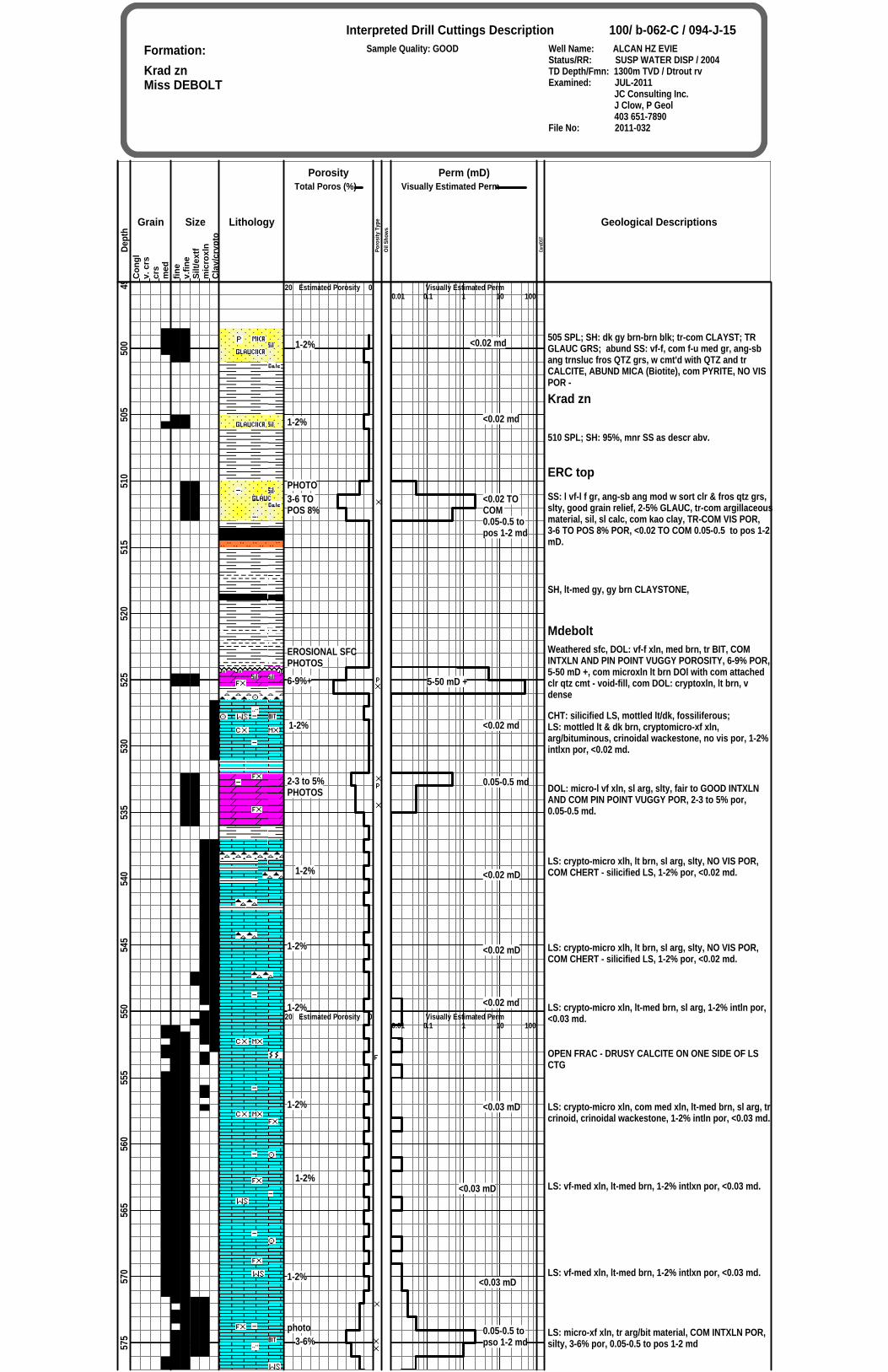
Interpreted Drill Cuttings Description 200/c-056-E / 094-O-08/00Formation: Well Name: ECA ETSHO
Status/RR: N/A / MAR2010TD Depth/Fmn: Proj 2738m / Dkeg rExamined: SEP-2011 JC Consulting Inc. J Clow, P Geol 403 651-7890File No: 2011-032
Sample Quality: GOOD
MISS DEBOLT
Dept
h
Grain
Con
glv.
crs
crs
med
Size
fine
v.fin
eSi
lt/ex
tfm
icro
xln
Cla
y/cr
ypto
Lithology
PorosityTotal Poros (%)
Poro
sity
Typ
eOi
l Sho
ws
Perm (mD)Visually Estimated Perm
Core/
DST
Geological Descriptions
5253
053
554
054
555
055
556
056
557
057
580
20 Estimated Porosity 0
20 Estimated Porosity 0
1-2%
1-2% earthy/intxlnpor
photos
3-6 to pos 8%
1-2 or 3% intlxn por
1-2 or 3% intlxn por
1-3%
Visually Estimated Perm0.01 0.1 1 10 100
Visually Estimated Perm0.01 0.1 1 10 100
<0.01 mD
<0.01 mD
<0.02 md
1-5 to pos 10-50 md
<0.05 md
<0.05 md
<0.05 mD
SH, com SLTST
K RAD ZONE
SH, com white bentonite.
M DEBOLT
CHERT: abund in spl, med-dk gy and com brn, tr attacheXLN CALCITE - POSSIBLE FRAC FILL - NO INDICATION OF POROSITYLS: crypto-microxln, arg, earthy, 1% por, 0.01 md
LS: crypto-micro to com f xln, arg, earthy in part, poor intlxn por, 1-2%, 0.01 md.
LS: micro-vf & f xln, sl arg, sl earthy, 1-2% inxln por, <0.02 md.
DOL: micro-predom vf-f xln, med-dk brn OIL STAINED, sl arg, tr bit, GOOD INTXLN AND PIN POINT VUGGY POR WITH DRUSY LINING, SUCROSIC IN PART, 3-6 to pos 8% por, 1-5 to pos 10-50 mD, golden yel flor and instant fast streaming yellow cut.
DOL: micro-xf xln, com vf-f xln, sl arg-arg, 1-2 or 3% po<0.05 md.
DOL: micro-xf xln, com vf-f xln, sl arg-arg, 1-2 or 3% po<0.05 md.
LS: micro-xf to com vf xln, lt-med brn, comly EARTHY, 1-3% por, <0.05 md.
LS: wh, chalky, to comly earthy as abv, 1-2 or 3% por, <0.03 md.

Interpreted Drill Cuttings Description 200/d-012-L / 094-O-15/00Formation: Sample Quality: good Well Name: EOG MAXHAMISH
Status/RR: POTENTIAL GAS / 2006TD Depth/Fmn: 3103m / Dkeg rExamined: JUL-2011 JC Consulting Inc. J Clow, P Geol 403 651-7890File No: 2011-032
Cretaceous SSMiss Debolt
Dept
h
Grain
Con
glv.
crs
crs
med
Size
fine
v.fin
eSi
lt/ex
tfm
icro
xln
Cla
y/cr
ypto
Lithology
PorosityTotal Poros (%)
Poro
sity
Typ
eOi
l Sho
ws
Perm (mD)Visually Estimated Perm
Core/
DST
Geological Descriptions
5051
051
552
052
553
053
554
054
555
055
556
056
557
057
558
058
5
20 Estimated Porosity 0
20 Estimated Porosity 0
? no sand in spl as suggested bygamma log.
photo3-6 to com 8%
photo
6-9%
8-14%
7-9 to pos 12%
6-9%
7-9 to pos 12%
PHOTO
7-9 to pos 12%
3-6%
1-3 to pos 5% micro clay por, <0.02 mD.
WEATHERED SFC
Visually Estimated Perm0.01 0.1 1 10 100
Visually Estimated Perm0.01 0.1 1 10 100
0.05-0.5 mD to pos 1 mD
1-5 to com 10+ md
10-50 mD
1-5 to pos 5-10 mD
0.05-0.5 topos 1-3 md
1-5 to pos 5-10 mD
1-5 to pos 5-10 mD
0.02-0.05 md
SH: med-dk gy
Krad zn
CRETACEOUS SS
SS: vf-l f gr, ang-sb ang qtzose, com to locally abund GLAUCONITE, weakly consol, sil, sl calc, FAIR TO GOOD GRN RELIEF, TR-COM VIS POR, 3-6 to com 8%, 0.05-0.5 mD to pos 1 or 2 md, lt brn OIL STAIN, instant wh milky cut.
SS: vf-l med gr, ang-sb ang fros qtzsoe, com kao clay and silt, sil, calc, COM VIS INTGR POR, 6-9% por, 1-5 mD to com 10+ mD, lt brn OIL stain, weak milky wh solvent cut.
SS: f-l & com u med gr, ang-sb ang qtz grs with com overgrths, slsty, tr KAO, rr glauc, excellent intgr vis por,8-14% por. 10-50 mD +.
SS: vf-l f gr, ang-sb ang fros qtz grs, rr glauc, com slt & kao clay, good grn relief, mod-weakly consolidated, comly DISSAGG in spl, com vis por, 7-9 to pos 12%, 1-5 to pos 5-10 mD
SS: as abv, incr in KAO clay, 6-9% por, 0.05-0.5 to pos 1-3 md.
SS: vf-l f gr, ang-sb ang fros qtz grs, rr glauc, com slt & kao clay, good grn relief, mod-weakly consolidated, comly DISSAGG in spl, com vis por, 7-9 to pos 12%, 1-5 to pos 5-10 mD
SS: vf-l f gr, ang-sb ang fros qtz grs, rr glauc, com slt & kao clay, good grn relief, mod-weakly consolidated, comly DISSAGG in spl, com vis por, 7-9 to pos 12%, 1-5 to pos 5-10 mD
SS: as abv, increasing amount of KAO clay, RR VIS POR, 3-6% predom micro clay por, 0.02-0.05 md.
SS: as abv, increasing amount of KAO clay, RR VIS POR, 3-6% predom micro clay por, 0.02-0.05 md.
SH, abund loose dissagg sand grains: vf-f & com l med gr, sb ang-sb rdd fros grs, com attached KAO xclay, com glauc, com carb mat, infer no vis por, no vis por.
SH, com varicoloured shale, weathered surface, com SIDERITE SPHERICLES.

590
595
600
605
610
615
620
25
20 Estimated Porosity 0
Photo5-9%
1-2 or 3%
1%
1-2%
1-2%
Visually Estimated Perm0.01 0.1 1 10 100
1-5 to pos 10+ mD
<0.03 md
<0.02 mD
<0.02 md
<0.02 mD
CHERT: com wh-lt gy chert fragments, com white chalkweathered chert, weathered zone.DOL: vf-l f xln, dk brn OIL STAINED, excellent vis por, 5-9% por, 1-5 to pos 10+ mD.
LS: crypto-micro xln, com micro-vf xln, 1-2 or 3% por, <0.03 md.
LS: crypto-micro xln, COM CRINOIDS, crinoidal packstone, sl arg, NO VIS POR, 1-2%, <0.02 md.
LS: crypto-micro xln, COM CRINOIDS, crinoidal packstone, sl arg, NO VIS POR, 1-2%, <0.02 md.
LS: crypto-micro xln, comly argillaceous, 1-2%.

Interpreted Drill Cuttings Description 200/d-075-G / 094-O-08/00Formation: Well Name: DEVON NEC HZ KOMIE
Status/RR: N/A / MAY 2010TD Depth/Fmn: PROJ TD / 4100m / DEVIEExamined: AUG-2011 JC Consulting Inc. J Clow, P Geol 403 651-7890File No: 2011-032
Sample Quality: GOOD
MISS DEBOLT
Dept
h
Grain
Con
glv.
crs
crs
med
Size
fine
v.fin
eSi
lt/ex
tfm
icro
xln
Cla
y/cr
ypto
Lithology
PorosityTotal Poros (%)
Poro
sity
Typ
eOi
l Sho
ws
Perm (mD)Visually Estimated Perm
Core/
DST
Geological Descriptions
5858
559
059
560
060
561
061
562
062
563
063
540
20 Estimated Porosity 0
20 Estimated Porosity 0
3-6%
3-6% predom micro clay por
1-2 to com 3-5%
1%
2-3-6%
1-2%
1-3% to tr 6%
1%
1%
1%
Visually Estimated Perm0.01 0.1 1 10 100
Visually Estimated Perm0.01 0.1 1 10 100
<0.05 mD
<0.02 to strky <0.05 md
0.01 md
<0.5 mD
<0.02 md
0.05-0.3 mD
<0.02 mD
<0.02 md
0.02 md
SH, com white speckled calcite
K rad zone
SS: silt-l vf gr, tr GLAUC, OIL STAINED, sil, com KAO clay, tr vis por, micaceous, 3-6% POR, 0.02-0.1 md; com BLKY WHITE CALCITE - POSSIBLE FRAC FILL ?
SS: vf-f gr with abund OIL stained KAO clay matrix, 3-6% predom micro clay por, <0.05 md?SH: black, blocky.M DEBOLT
DOL: vf-f xln, com vf-med xln, slty-sdy, earthy matrix, heavily OIL stained, 1-2 to com 3-5% por, <0.02 to strky <0.05 md.
LS: crypto-micro xln, comly arg mat, tr bit.
DOL: vf xln, gy, 2-3 to pos 6%, 0.05-0.3 md.
U RUNDLE
CHT: dk brn blk silicified LS.LS: chalky, weathered.
LS: micro-vf xln, lt-vf xln, 1-3%, <0.02 mD; com LS: fossiliferous, arg, p por.
LS: crypto-micro xln, sl arg, tr bit, p intxln por.SH: blk
LS: vf-f xln, lt-dk brn, v sl arg, p intxln por.

Interpreted Drill Cuttings Description 200/d-99-I / 94-O-01/00Formation: Sample Quality: good Well Name: IMP KOMIE
Status/RR: DRLD & ABNDTD Depth/Fmn: 2497m / Dkeg rExamined: JUL-2011 JC Consulting Inc. J Clow, P Geol 403 651-7890File No: 2011-032
K Rad zonK BlueskyM Rundle
Dept
h
Grain
Con
glv.
crs
crs
med
Size
fine
v.fin
eSi
lt/ex
tfm
icro
xln
Cla
y/cr
ypto
Lithology
PorosityTotal Poros (%)
Poro
sity
Typ
eOi
l Sho
ws
Perm (mD)Visually Estimated Perm
Core/
DST
Geological Descriptions
5353
554
054
555
055
556
056
557
057
558
058
559
059
500
20 Estimated Porosity 0
20 Estimated Porosity 0
1-2%
PHOTOweathered
6-10%
3-5 to pos 6-9%
1-2 or 3%
1-2 to pos2-4%
1-2 to pos 2-4%
1-3%
PHOTO
2-3% to 5-9% inxlnpor
1-2%
1-2%
Visually Estimated Perm0.01 0.1 1 10 100
Visually Estimated Perm0.01 0.1 1 10 100
<0.02 mD
1-5 to 10+ mD, com DISSOLUTIOSIL POR
1-5 + mD
<0.02 mD
<0.02 to pos <0.05 mD
<0.02 to pos <0.05 mD
<0.03 mD
10+ mD
<0.02 md
<0.02 md
535 SPL; SH: dk brn blk, blky-fis, com CALCITE; blky, posible FRAC FILL.
Krad zn
540 SPL; SS: vf-f & tr l med gr, clr ang qtzose, abund MICA (biotite), qtzose, com calcite, NO VSI POR.
SH, com SS as abv, tr CLYST.
KblueskyCONGL: abund wh brkn CHERT PEBS, com clr ang qtz grs with abund wh-lt gy CHERT grs, tr-com GY rounded CHERT PEBBLES with com attached vf-med gr porous SS, com qtz/calcite cmt, rr GLAUC, OIL STAINED, COM GOOD INTGRANULAR POROSITY, com weathered DISSOLUTION SIL POR, 6-10% por, 1-5 to 10+ mD, golden yel flor/ streaming solvent cut.
555m SPL; SH, abund chert/qtz as described abv with com dissolution por and OIL staining, com good predom qtz dissoultion porosity,
SS: vf gr clr qtzose, v calcareous grading to sdy LS, com argillaceous material, OIL stained - no flor or solvent cut, rr vis poir 1-3%, <0.02 mD
SH, dk gy blk.
Upper Rundle
LS: crypto-micro to com vf xln, xln, med-dk brn, com crinoidal packstone, sl argillaceous, no vis por.LS: tr-com BRN OIL STAINED EARTHY LS, tr-com oil stained vf xln, com WH CHALKY TEXTURE, 1-2 to pos 2-4%, <0.02 to pos <0.05 mD.
LS: chalky texture, white-off wh to com vf xln, com crinoids - crinoidal whackestone-packst, micro-vf xln, xom f xln, 1-3% intxln por, tr BIT LINED VUG POR, <0.03mD
LS: few ctgs, vf-f xln, SUCROSIC TEXTURE, GOOD INTXLN POR, DK BRN OIL STAINED, 5-9% intxln por, 10+ mD; com LS: micro-vf & f xln, 2-3% intxln por, oil stained, <0.05 md.
LS: crypto-micro xln, lt brn, tr crinoids, sl arg, p intlxn por, 1-2%, <0.02 md
LS: crypto-micro xln, med-dk brn, argillaceous, tr bit, sl slty, p intxln por.