horizontal cable infill - jamvinyl.com
TRANSCRIPT

Cable Needle
• These directions are only a guide and may not address every situation.
• Always wear proper safety equipment while assembling and installing.
• The installer should obtain all required building permits and follow all installation procedures in accordance with applicable building code requirements.
• Key-Link Fencing and Railing Inc. shall not be held liable for improper or unsafe installations.
• Applying paint, other than Key-Link’s touch up paint, will void your warranty.
• To ensure proper coverage by our warranty please visit our website and complete the warranty form and mail to: Key-Link Fencing & Railing, Inc., 150 Orlan Road, New Holland, PA 17557
What's Included• Top Rail & Baluster(s)• Mounting Brackets & Screws
(Predrilled Posts, Caps, & Trim packaged separate)• Stainless Steel Cable Roll (optional)
Quick TipWear clean, new gloves when handling stainless steel parts to prevent corrosion from oil and dirt.
HORIZONTAL
American & Arabian Series
Available from Key-Link
Cable Cutter
Tension Gauge
CABLE INFILL
Recommended Tools• Safety Glasses• Tape Measure & Pencil• Level• Drill & Bits (1/4", 3/16", 17/32")• Hammer Drill (if concrete)• Circular Saw w/ Fine-Tooth
Aluminum Cutting Blade• Rubber Mallet
Top Rail MountCable Receiver
Baluster Mount
Flat Head Screws Pan Head Screws
Post CapPost TrimStai
r Pos
t
Leve
l Pos
t
Cable Release Key
KFRIG161208
Cable Vise Grip
KeyLinkOnline.com
*Reference Local Building Codes for Railing and Cable Installation requirements
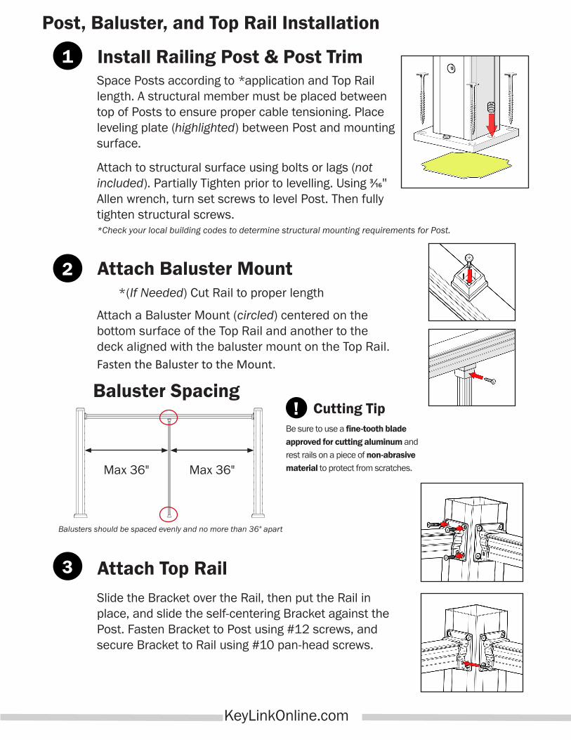
Attach a Baluster Mount (circled) centered on the bottom surface of the Top Rail and another to the deck aligned with the baluster mount on the Top Rail.Fasten the Baluster to the Mount.
Install Railing Post & Post Trim
Slide the Bracket over the Rail, then put the Rail in place, and slide the self-centering Bracket against the Post. Fasten Bracket to Post using #12 screws, and secure Bracket to Rail using #10 pan-head screws.
Attach Baluster Mount
Be sure to use a fine-tooth blade approved for cutting aluminum and rest rails on a piece of non-abrasive material to protect from scratches.
Cutting TipBaluster Spacing
Balusters should be spaced evenly and no more than 36" apart
Max 36" Max 36"
*(If Needed) Cut Rail to proper length
Attach Top Rail
Post, Baluster, and Top Rail Installation
1
2
!
3
Space Posts according to *application and Top Rail length. A structural member must be placed between top of Posts to ensure proper cable tensioning. Place leveling plate (highlighted) between Post and mounting surface.
Attach to structural surface using bolts or lags (not included). Partially Tighten prior to levelling. Using 3/16" Allen wrench, turn set screws to level Post. Then fully tighten structural screws.*Check your local building codes to determine structural mounting requirements for Post.
KeyLinkOnline.com

Thread the cable through all the Posts and balusters starting from one end
Post to the next end Post.
Use a 3/16" Allen Wrench, to tightenTip: Tighten every other row first,
working away from the center.
Place Post Cap on Post and use soft or rubber mallet to set in place. Snap the Post Trim halves together around the
bottom of each Post.
Unwind enough cable to reach to the opposite end Post and pull tight. Removing
all slack from each section.
Remove Cable Slack and cut 1¼" longer than inside face of the end Post Receiver.
Insert Cable into the Receiver by twisting in a clockwise direction. (Optional use Cable
Vice Grip Tool)
1¼"
Cable Rail Installation
Once both cable ends have been inserted; place body weight onto each cable to set/
anchor them firmly inside Receivers. (Before continuing to Step-7) Repeat previous steps for the remaining Post and Baluster rows.
A Tension Gauge (available from Key-Link) can be used to tighten the cable to the desired tension. When tightening cable; watch to ensure the cable is not spinning which could indicate the receiver is fully tightened. Do not overtighten!Cable can release if over tightenedCheck with your local building inspector about local codes regarding cable tension.
Insert the cable into the end Post Receiver as far as it will go. Gently twist clockwise on
the cable to until it is secure.
Check with your local building inspector on how close the cables
should be if drilling the Post yourself.
27/8"
27/8"
23/4"
Typical Spacing
27/8"
5
6
4
21
7
3
KeyLinkOnline.com
Check to make sure the Lock Jaw housing (highlighted) is threaded all the way out to the cap to maximize tensioning capacity.
Before Tensioning
After Tensioning
To use the Cable
Release Key,
slide it over the
cable into the receiver, and push to
release the cable. For use before the
cable is fully tightened.
The Cable
Needle is
used for
threading the cable through
balusters & posts that do not
have fittings.
Cable Release Key Cable Needle

150 Orlan Road ● New Holland, PA 17557
When doing stair sections, mount them as shown below: !
Stair Rail Installation
Use typical spacing (27/8") to mark each additional hole on both sides of the Bottom Stair Post, and
drill a 17/32" level hole at each mark.Note: On a Line Post, or Baluster; 3/16" holes
should be drilled at the appropriate stair angle.
Ensure that the stairs' Top Rail doesn’t exceed the level rail height of the opposite Rail.
Measure from inside edge between Posts (then subtract 1/4")
Attach both Baluster stair mounts, and Up and Down Top rail mount (Refer to pg.2 Step 2 & 3)
Cut Upper and Lower ends of Top rails at opposite angles. To ensure Rails align
properly.(Standard stair angle is 34°)
321
KeyLinkOnline.com
On stairs; use the Post with 5" spacing to the bottom receiver. Standard Posts can only be used on stairs when stair angle is 34°. For
all other angles, blank Posts will need to be used and custom drilled.
4
NOTE: How to Loosen Stuck Jaws
In the event that the jaws of the post receiver become stuck.
Insert an Allen Wrench into the open end of the cable receiver, and press until you can feel the internal spring release.
!
To determine first hole placement; use a straight edge laid flat on the nose of the stairs, and measure off the surface to the first hole on the Level Post, and translate that measurement to each Post/ Baluster.
Typ. Spacing
6Level Post
Mark back side of Bottom Stair Post
Bottom Stair Post
5