horizontal alignments and cross …people.sunyit.edu/~barans/classes/ctc440/pdf/inroads...
TRANSCRIPT
HORIZONTAL ALIGNMENTS
AND CROSS SECTIONS
April 2006
NEW YORK STATE DEPARTMENT OF TRANSPORTATION

This page intentionally left blank
i
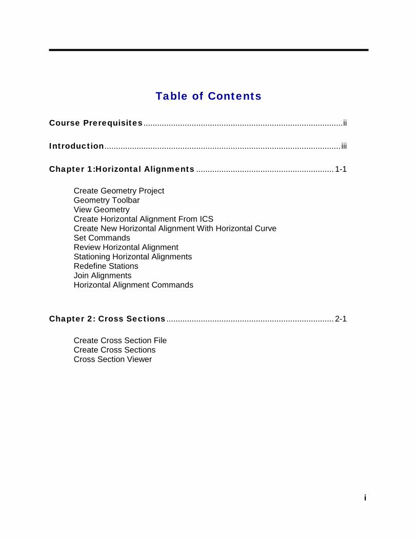
Table of Contents
Course Prerequisites.......................................................................................ii Introduction....................................................................................................... iii Chapter 1:Horizontal Alignments ............................................................ 1-1 Create Geometry Project Geometry Toolbar View Geometry Create Horizontal Alignment From ICS Create New Horizontal Alignment With Horizontal Curve Set Commands Review Horizontal Alignment Stationing Horizontal Alignments Redefine Stations Join Alignments Horizontal Alignment Commands Chapter 2: Cross Sections ......................................................................... 2-1 Create Cross Section File Create Cross Sections Cross Section Viewer

Horizontal Alignments and Cross Sections
ii
Course Prerequisites The following is a list of requirements that must be met by a student before entering class:
√ Should have MicroStation experience.
√ Should have a basic understanding of the InRoads environment.
√ Should have a basic knowledge of design criteria for creating horizontal alignments.

iii
Introduction
In this class we will learn multiple ways of creating a horizontal alignment and the steps required to achieve an accurate alignment. The alignments will be used to create cross sections.

Horizontal Alignments
1- 1
Chapter 1
Chapter 1 Horizontal Alignments
Introduction...
This chapter will demonstrate the multiple tools available to create an accurate and precise horizontal alignment.

Horizontal Alignments and Cross Sections
1- 2
A Geometry Project can also be created by going to File > New or type Ctrl + N Type AZ=0, tag view and turn depth lock on. Turn on pencil and write lock.
*
Horizontal Alignments
1- 3
Chapter 1
Horizontal alignments are used to describe a roadway’s horizontal geometry. In InRoads, horizontal alignments are stored in a geometry file with an *.alg extension. COGO points, vertical alignments and superelevation alignments are also stored in the geometry file.
Horizontal alignments can be created utilizing many different methods. It is very important that the designer know what the alignments will be used for in construction as well as design before alignment creation.
Create an InRoads Workfile in MicroStation
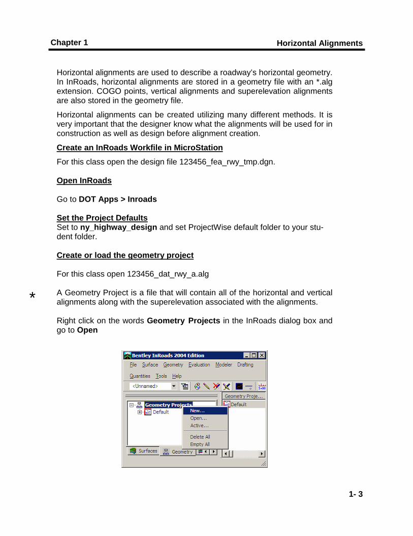
For this class open the design file 123456_fea_rwy_tmp.dgn. Open InRoads Go to DOT Apps > Inroads Set the Project Defaults Set to ny_highway_design and set ProjectWise default folder to your stu-dent folder. Create or load the geometry project For this class open 123456_dat_rwy_a.alg A Geometry Project is a file that will contain all of the horizontal and vertical alignments along with the superelevation associated with the alignments. Right click on the words Geometry Projects in the InRoads dialog box and go to Open
*

Horizontal Alignments and Cross Sections
1- 4
Horizontal Alignments
1- 5
Chapter 1
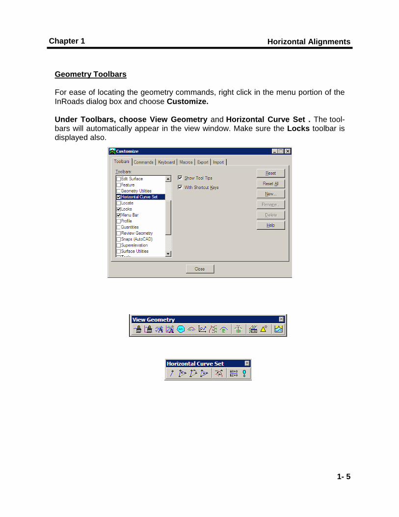
Geometry Toolbars For ease of locating the geometry commands, right click in the menu portion of the InRoads dialog box and choose Customize.
Under Toolbars, choose View Geometry and Horizontal Curve Set . The tool-bars will automatically appear in the view window. Make sure the Locks toolbar is displayed also.
Horizontal Alignments and Cross Sections
1- 6
*
Horizontal Alignments
1- 7
Chapter 1
View Geometry
View Active Horizontal
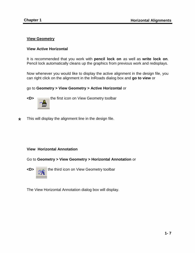
It is recommended that you work with pencil lock on as well as write lock on. Pencil lock automatically cleans up the graphics from previous work and redisplays.
Now whenever you would like to display the active alignment in the design file, you can right click on the alignment in the InRoads dialog box and go to view or
go to Geometry > View Geometry > Active Horizontal or
<D> the first icon on View Geometry toolbar
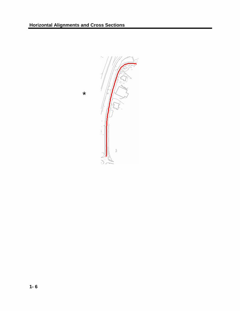
This will display the alignment line in the design file.
View Horizontal Annotation
Go to Geometry > View Geometry > Horizontal Annotation or
<D> the third icon on View Geometry toolbar
The View Horizontal Annotation dialog box will display.
*
Horizontal Alignments and Cross Sections
1- 8
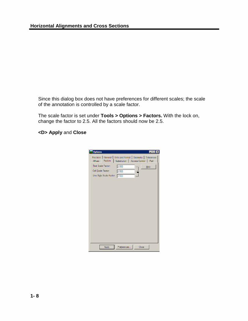
Since this dialog box does not have preferences for different scales; the scale of the annotation is controlled by a scale factor. The scale factor is set under Tools > Options > Factors. With the lock on, change the factor to 2.5. All the factors should now be 2.5. <D> Apply and Close
Horizontal Alignments
1- 9
Chapter 1
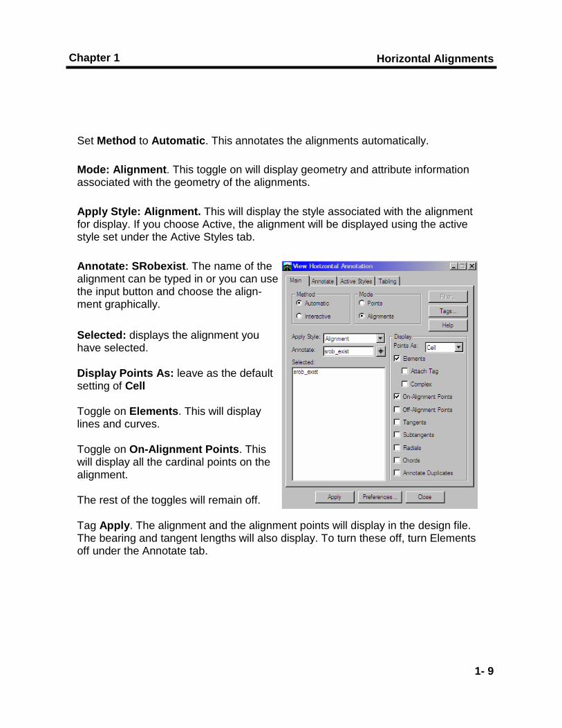
Set Method to Automatic. This annotates the alignments automatically.
Mode: Alignment. This toggle on will display geometry and attribute information associated with the geometry of the alignments.
Apply Style: Alignment. This will display the style associated with the alignment for display. If you choose Active, the alignment will be displayed using the active style set under the Active Styles tab.
Annotate: SRobexist. The name of the alignment can be typed in or you can use the input button and choose the align-ment graphically. Selected: displays the alignment you have selected. Display Points As: leave as the default setting of Cell Toggle on Elements. This will display lines and curves. Toggle on On-Alignment Points. This will display all the cardinal points on the alignment. The rest of the toggles will remain off. Tag Apply. The alignment and the alignment points will display in the design file. The bearing and tangent lengths will also display. To turn these off, turn Elements off under the Annotate tab.

Horizontal Alignments and Cross Sections
1- 10
Horizontal Alignments
1- 11
Chapter 1
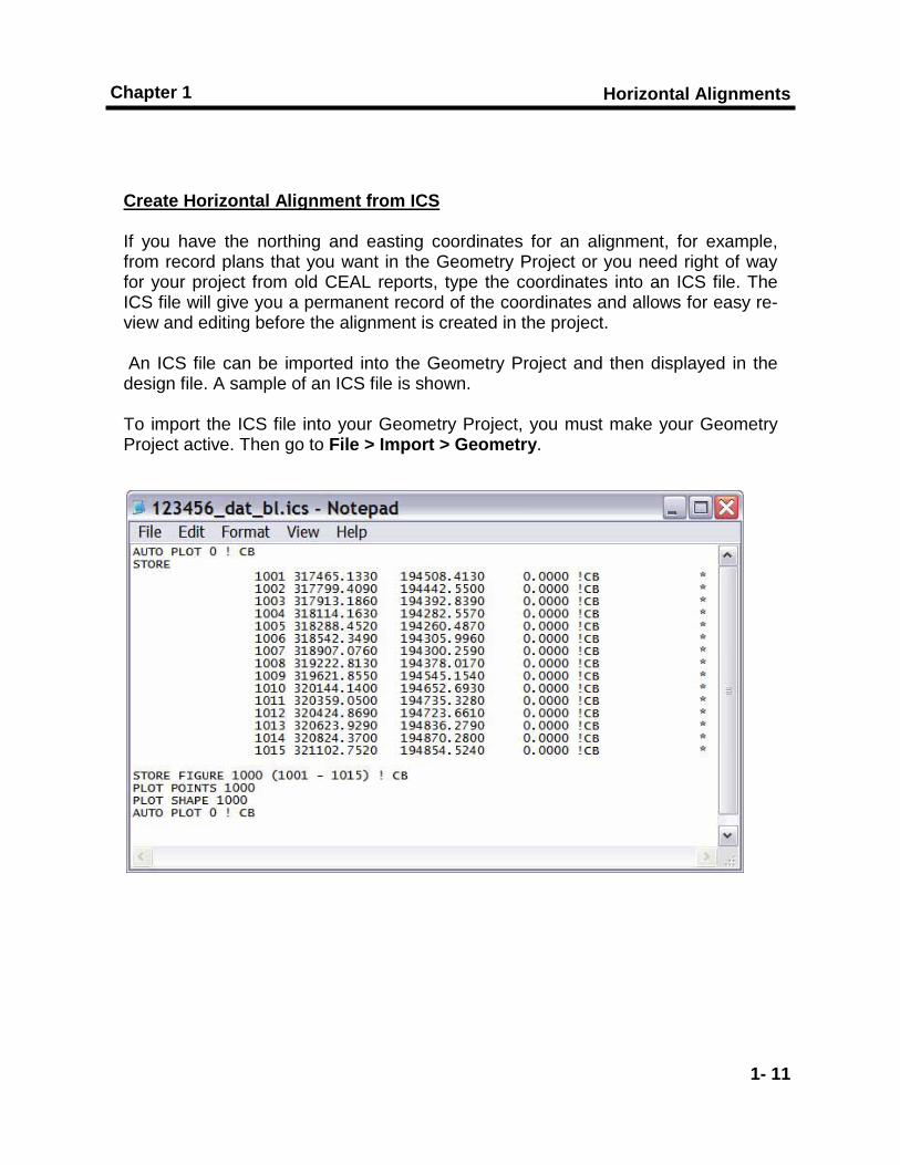
Create Horizontal Alignment from ICS If you have the northing and easting coordinates for an alignment, for example, from record plans that you want in the Geometry Project or you need right of way for your project from old CEAL reports, type the coordinates into an ICS file. The ICS file will give you a permanent record of the coordinates and allows for easy re-view and editing before the alignment is created in the project. An ICS file can be imported into the Geometry Project and then displayed in the design file. A sample of an ICS file is shown. To import the ICS file into your Geometry Project, you must make your Geometry Project active. Then go to File > Import > Geometry.
Horizontal Alignments and Cross Sections
1- 12
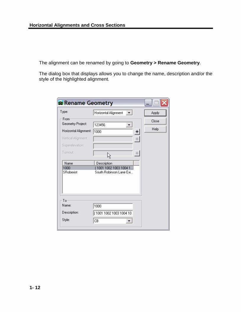
The alignment can be renamed by going to Geometry > Rename Geometry. The dialog box that displays allows you to change the name, description and/or the style of the highlighted alignment.
Horizontal Alignments
1- 13
Chapter 1
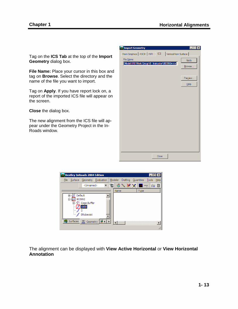
Tag on the ICS Tab at the top of the Import Geometry dialog box. File Name: Place your cursor in this box and tag on Browse. Select the directory and the name of the file you want to import. Tag on Apply. If you have report lock on, a report of the imported ICS file will appear on the screen. Close the dialog box. The new alignment from the ICS file will ap-pear under the Geometry Project in the In-Roads window. The alignment can be displayed with View Active Horizontal or View Horizontal Annotation

Horizontal Alignments and Cross Sections
1- 14
Horizontal Alignments
1- 15
Chapter 1
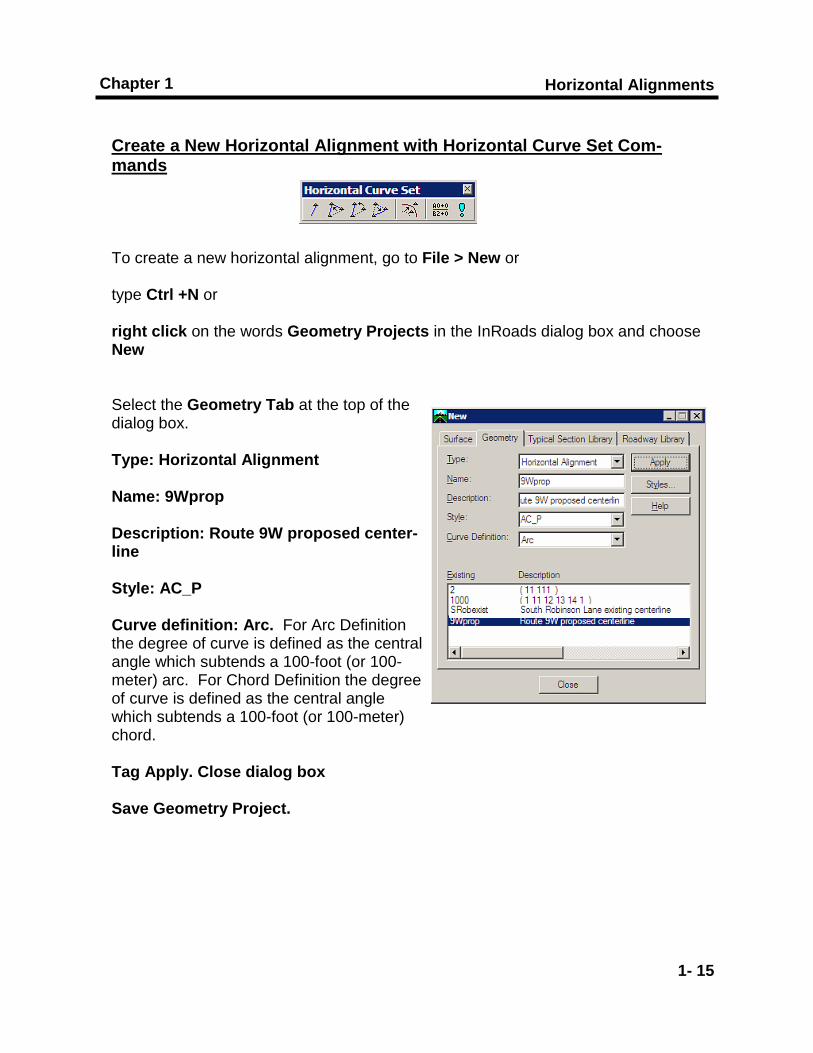
Create a New Horizontal Alignment with Horizontal Curve Set Com-mands To create a new horizontal alignment, go to File > New or type Ctrl +N or right click on the words Geometry Projects in the InRoads dialog box and choose New Select the Geometry Tab at the top of the dialog box. Type: Horizontal Alignment Name: 9Wprop Description: Route 9W proposed center-line Style: AC_P Curve definition: Arc. For Arc Definition the degree of curve is defined as the central angle which subtends a 100-foot (or 100-meter) arc. For Chord Definition the degree of curve is defined as the central angle which subtends a 100-foot (or 100-meter) chord. Tag Apply. Close dialog box Save Geometry Project.

Horizontal Alignments and Cross Sections
1- 16
Horizontal Alignments
1- 17
Chapter 1
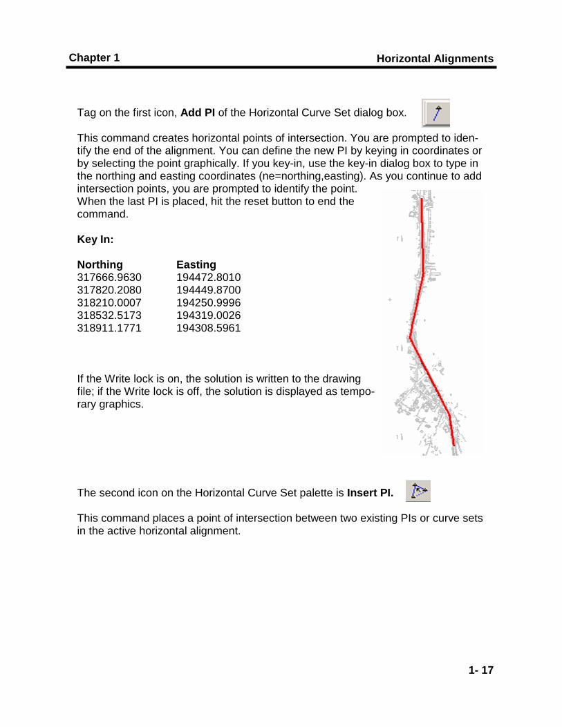
Tag on the first icon, Add PI of the Horizontal Curve Set dialog box. This command creates horizontal points of intersection. You are prompted to iden-tify the end of the alignment. You can define the new PI by keying in coordinates or by selecting the point graphically. If you key-in, use the key-in dialog box to type in the northing and easting coordinates (ne=northing,easting). As you continue to add intersection points, you are prompted to identify the point. When the last PI is placed, hit the reset button to end the command. Key In: Northing Easting 317666.9630 194472.8010 317820.2080 194449.8700 318210.0007 194250.9996 318532.5173 194319.0026 318911.1771 194308.5961 If the Write lock is on, the solution is written to the drawing file; if the Write lock is off, the solution is displayed as tempo-rary graphics. The second icon on the Horizontal Curve Set palette is Insert PI. This command places a point of intersection between two existing PIs or curve sets in the active horizontal alignment.

Horizontal Alignments and Cross Sections
1- 18
Horizontal Alignments
1- 19
Chapter 1
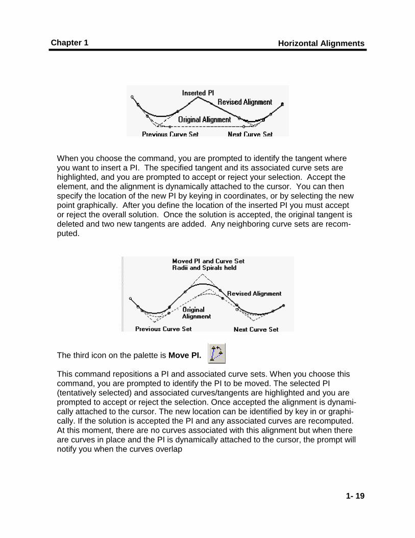
When you choose the command, you are prompted to identify the tangent where you want to insert a PI. The specified tangent and its associated curve sets are highlighted, and you are prompted to accept or reject your selection. Accept the element, and the alignment is dynamically attached to the cursor. You can then specify the location of the new PI by keying in coordinates, or by selecting the new point graphically. After you define the location of the inserted PI you must accept or reject the overall solution. Once the solution is accepted, the original tangent is deleted and two new tangents are added. Any neighboring curve sets are recom-puted. The third icon on the palette is Move PI. This command repositions a PI and associated curve sets. When you choose this command, you are prompted to identify the PI to be moved. The selected PI (tentatively selected) and associated curves/tangents are highlighted and you are prompted to accept or reject the selection. Once accepted the alignment is dynami-cally attached to the cursor. The new location can be identified by key in or graphi-cally. If the solution is accepted the PI and any associated curves are recomputed. At this moment, there are no curves associated with this alignment but when there are curves in place and the PI is dynamically attached to the cursor, the prompt will notify you when the curves overlap

Horizontal Alignments and Cross Sections
1- 20
Horizontal Alignments
1- 21
Chapter 1
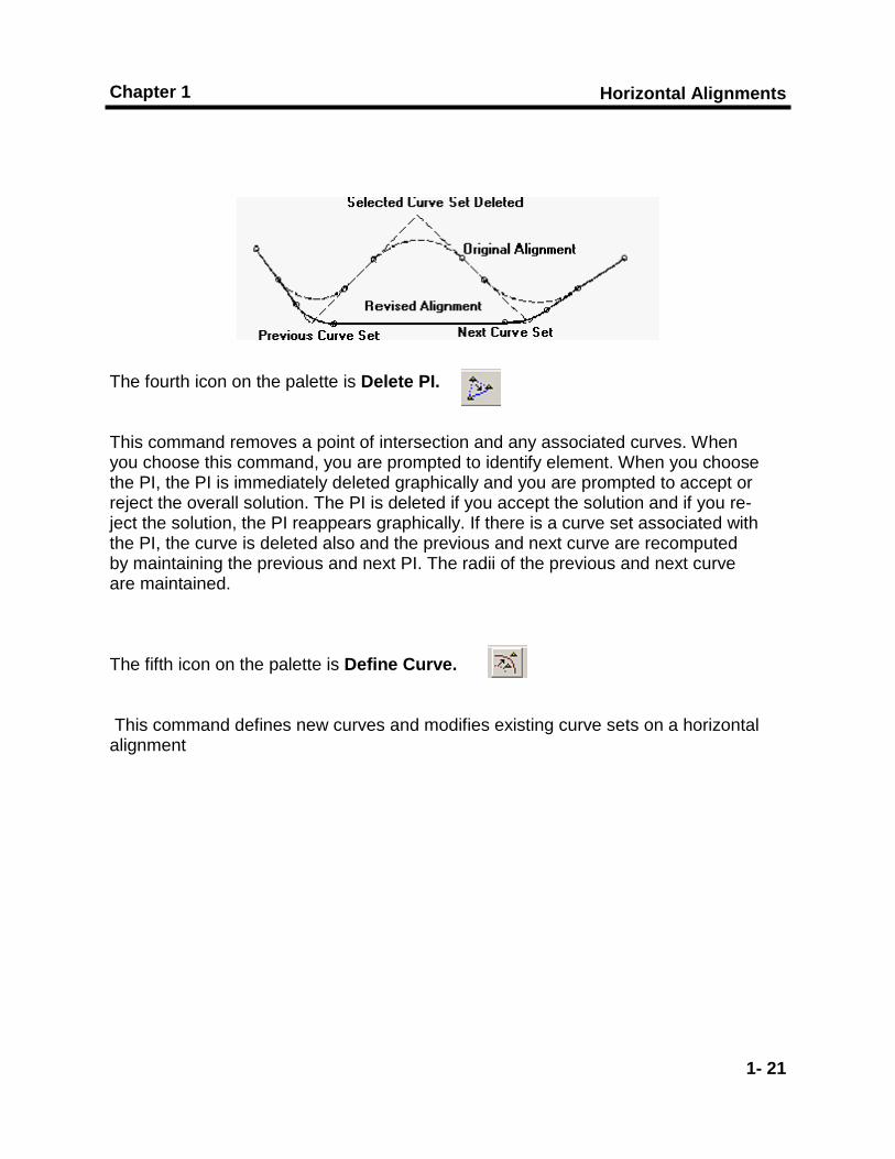
The fourth icon on the palette is Delete PI. This command removes a point of intersection and any associated curves. When you choose this command, you are prompted to identify element. When you choose the PI, the PI is immediately deleted graphically and you are prompted to accept or reject the overall solution. The PI is deleted if you accept the solution and if you re-ject the solution, the PI reappears graphically. If there is a curve set associated with the PI, the curve is deleted also and the previous and next curve are recomputed by maintaining the previous and next PI. The radii of the previous and next curve are maintained. The fifth icon on the palette is Define Curve. This command defines new curves and modifies existing curve sets on a horizontal alignment
Horizontal Alignments and Cross Sections
1- 22
To find the required length of spiral, we will need to know the following from our Design Criteria. For purposes of this lab: Assumed design speed = Vd = 90 km/h Min. Radius of curve = R = 336 E (max) = 6% The proposed roadway will be 2 lanes From Table 5-5 of the Highway Design Manual, the length of the Superelevation
Runoff is 46m.
Horizontal Alignments
1- 23
Chapter 1
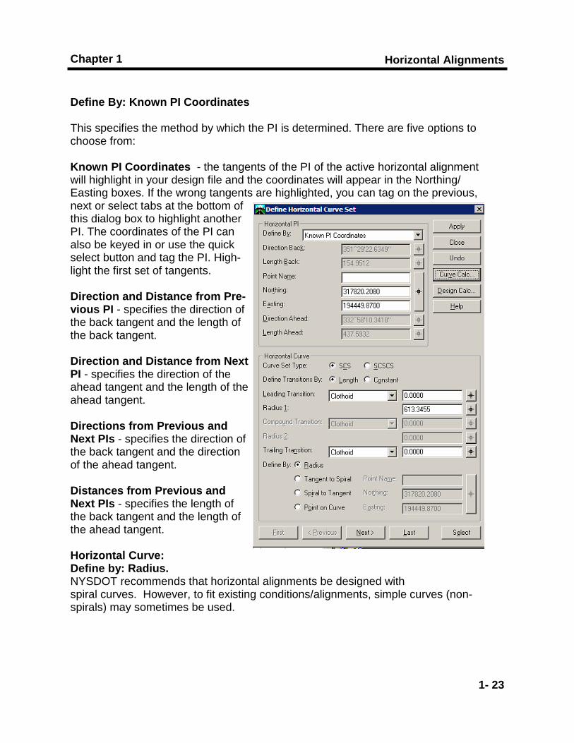
Define By: Known PI Coordinates This specifies the method by which the PI is determined. There are five options to choose from: Known PI Coordinates - the tangents of the PI of the active horizontal alignment will highlight in your design file and the coordinates will appear in the Northing/Easting boxes. If the wrong tangents are highlighted, you can tag on the previous, next or select tabs at the bottom of this dialog box to highlight another PI. The coordinates of the PI can also be keyed in or use the quick select button and tag the PI. High-light the first set of tangents. Direction and Distance from Pre-vious PI - specifies the direction of the back tangent and the length of the back tangent. Direction and Distance from Next PI - specifies the direction of the ahead tangent and the length of the ahead tangent. Directions from Previous and Next PIs - specifies the direction of the back tangent and the direction of the ahead tangent. Distances from Previous and Next PIs - specifies the length of the back tangent and the length of the ahead tangent. Horizontal Curve: Define by: Radius. NYSDOT recommends that horizontal alignments be designed with spiral curves. However, to fit existing conditions/alignments, simple curves (non-spirals) may sometimes be used.

Horizontal Alignments and Cross Sections
1- 24
Horizontal Alignments
1- 25
Chapter 1
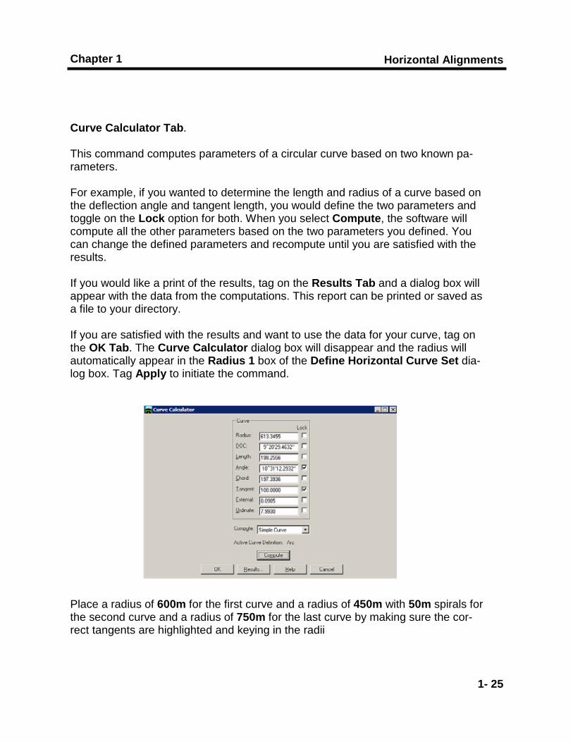
Curve Calculator Tab. This command computes parameters of a circular curve based on two known pa-rameters. For example, if you wanted to determine the length and radius of a curve based on the deflection angle and tangent length, you would define the two parameters and toggle on the Lock option for both. When you select Compute, the software will compute all the other parameters based on the two parameters you defined. You can change the defined parameters and recompute until you are satisfied with the results. If you would like a print of the results, tag on the Results Tab and a dialog box will appear with the data from the computations. This report can be printed or saved as a file to your directory. If you are satisfied with the results and want to use the data for your curve, tag on the OK Tab. The Curve Calculator dialog box will disappear and the radius will automatically appear in the Radius 1 box of the Define Horizontal Curve Set dia-log box. Tag Apply to initiate the command. Place a radius of 600m for the first curve and a radius of 450m with 50m spirals for the second curve and a radius of 750m for the last curve by making sure the cor-rect tangents are highlighted and keying in the radii
Horizontal Alignments and Cross Sections
1- 26
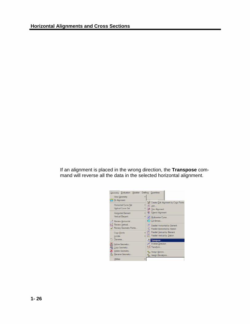
If an alignment is placed in the wrong direction, the Transpose com-mand will reverse all the data in the selected horizontal alignment.
Horizontal Alignments
1- 27
Chapter 1
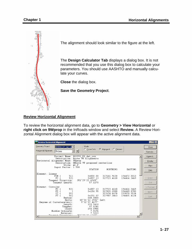
The alignment should look similar to the figure at the left. The Design Calculator Tab displays a dialog box. It is not recommended that you use this dialog box to calculate your parameters. You should use AASHTO and manually calcu-late your curves. Close the dialog box. Save the Geometry Project.
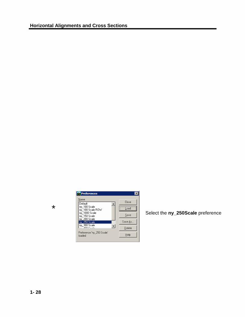
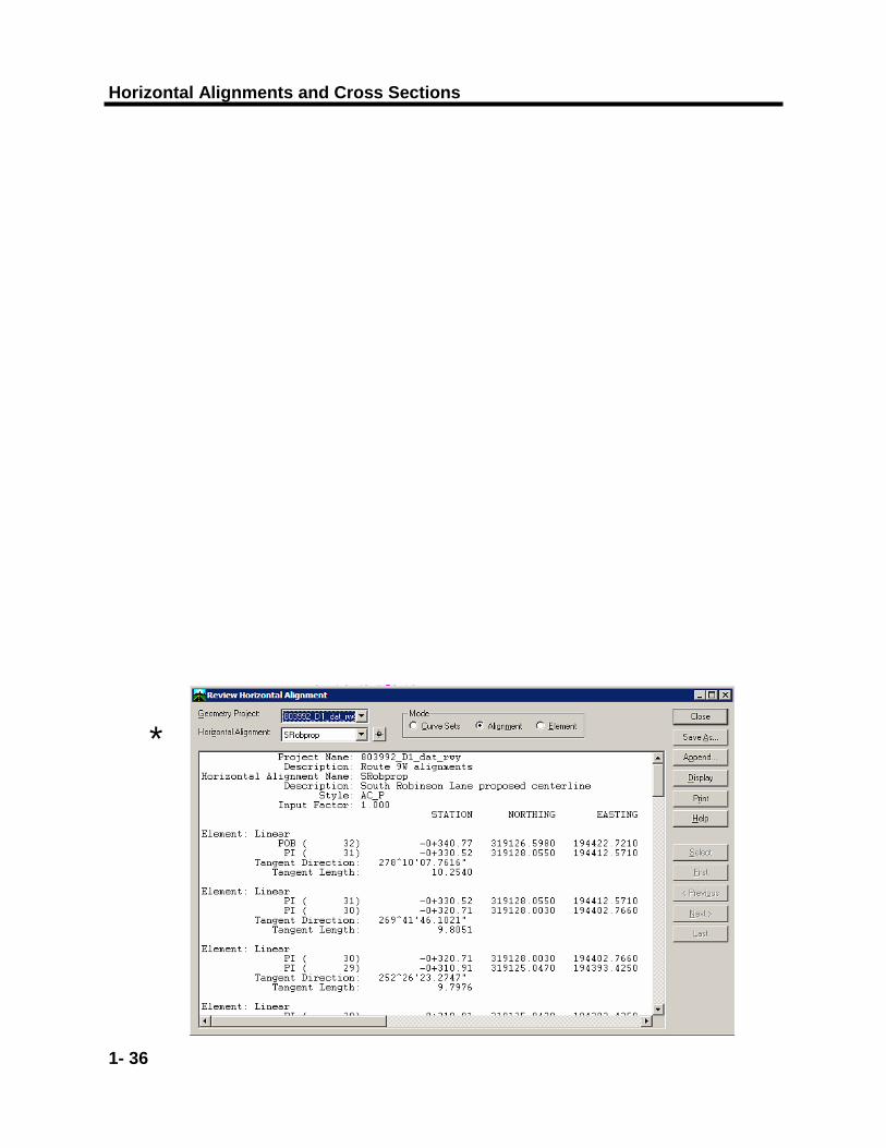
Review Horizontal Alignment To review the horizontal alignment data, go to Geometry > View Horizontal or right click on 9Wprop in the InRoads window and select Review. A Review Hori-zontal Alignment dialog box will appear with the active alignment data.
Horizontal Alignments and Cross Sections
1- 28
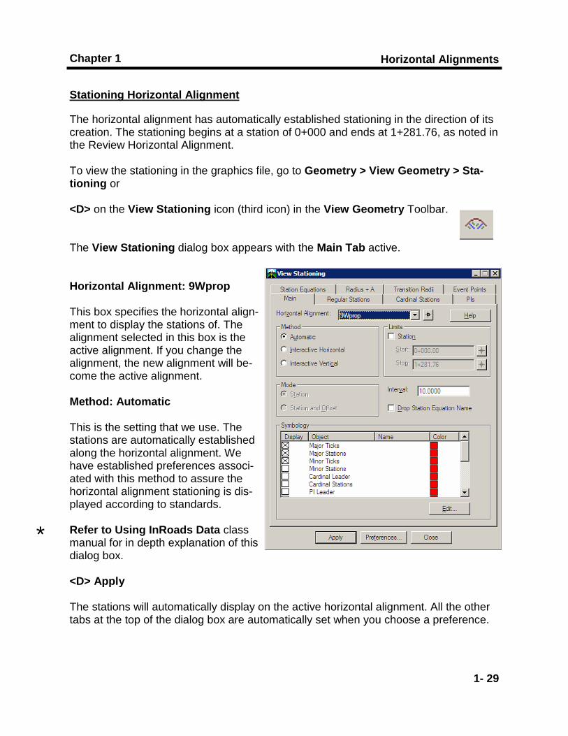
* Select the ny_250Scale preference
Horizontal Alignments
1- 29
Chapter 1
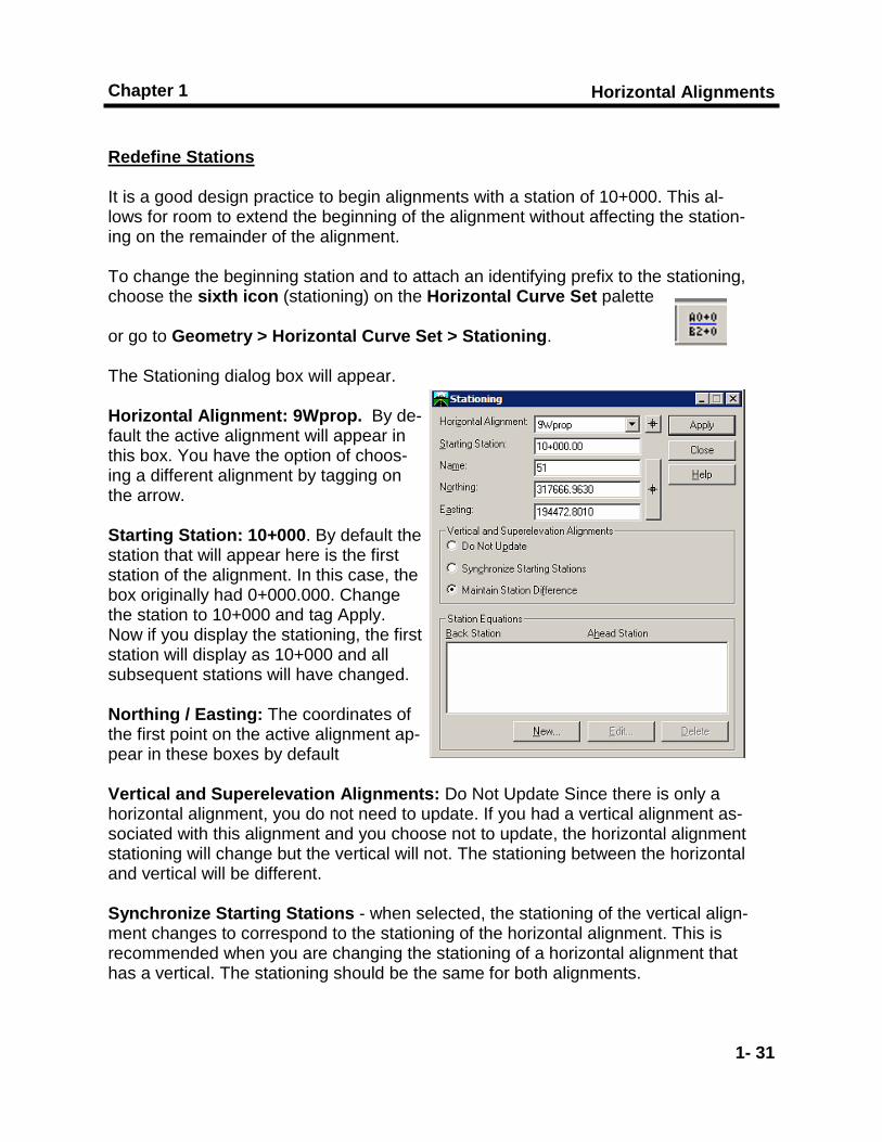
Stationing Horizontal Alignment The horizontal alignment has automatically established stationing in the direction of its creation. The stationing begins at a station of 0+000 and ends at 1+281.76, as noted in the Review Horizontal Alignment. To view the stationing in the graphics file, go to Geometry > View Geometry > Sta-tioning or <D> on the View Stationing icon (third icon) in the View Geometry Toolbar. The View Stationing dialog box appears with the Main Tab active. Horizontal Alignment: 9Wprop This box specifies the horizontal align-ment to display the stations of. The alignment selected in this box is the active alignment. If you change the alignment, the new alignment will be-come the active alignment. Method: Automatic This is the setting that we use. The stations are automatically established along the horizontal alignment. We have established preferences associ-ated with this method to assure the horizontal alignment stationing is dis-played according to standards. Refer to Using InRoads Data class manual for in depth explanation of this dialog box. <D> Apply The stations will automatically display on the active horizontal alignment. All the other tabs at the top of the dialog box are automatically set when you choose a preference.
*

Horizontal Alignments and Cross Sections
1- 30
Horizontal Alignments
1- 31
Chapter 1
Redefine Stations It is a good design practice to begin alignments with a station of 10+000. This al-lows for room to extend the beginning of the alignment without affecting the station-ing on the remainder of the alignment. To change the beginning station and to attach an identifying prefix to the stationing, choose the sixth icon (stationing) on the Horizontal Curve Set palette or go to Geometry > Horizontal Curve Set > Stationing. The Stationing dialog box will appear. Horizontal Alignment: 9Wprop. By de-fault the active alignment will appear in this box. You have the option of choos-ing a different alignment by tagging on the arrow. Starting Station: 10+000. By default the station that will appear here is the first station of the alignment. In this case, the box originally had 0+000.000. Change the station to 10+000 and tag Apply. Now if you display the stationing, the first station will display as 10+000 and all subsequent stations will have changed. Northing / Easting: The coordinates of the first point on the active alignment ap-pear in these boxes by default Vertical and Superelevation Alignments: Do Not Update Since there is only a horizontal alignment, you do not need to update. If you had a vertical alignment as-sociated with this alignment and you choose not to update, the horizontal alignment stationing will change but the vertical will not. The stationing between the horizontal and vertical will be different. Synchronize Starting Stations - when selected, the stationing of the vertical align-ment changes to correspond to the stationing of the horizontal alignment. This is recommended when you are changing the stationing of a horizontal alignment that has a vertical. The stationing should be the same for both alignments.
Horizontal Alignments and Cross Sections
1- 32
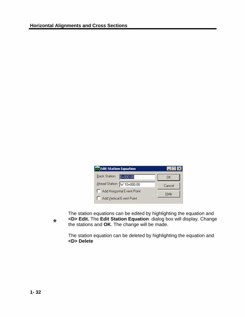
The station equations can be edited by highlighting the equation and <D> Edit. The Edit Station Equation dialog box will display. Change the stations and OK. The change will be made. The station equation can be deleted by highlighting the equation and <D> Delete
*
Horizontal Alignments
1- 33
Chapter 1
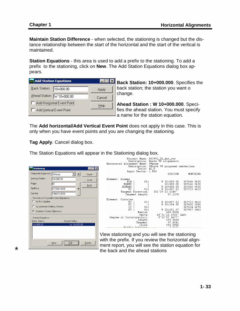
Maintain Station Difference - when selected, the stationing is changed but the dis-tance relationship between the start of the horizontal and the start of the vertical is maintained. Station Equations - this area is used to add a prefix to the stationing. To add a prefix to the stationing, click on New. The Add Station Equations dialog box ap-pears.
Back Station: 10+000.000. Specifies the back station; the station you want o change. Ahead Station : W 10+000.000. Speci-fies the ahead station. You must specify a name for the station equation.
The Add horizontal/Add Vertical Event Point does not apply in this case. This is only when you have event points and you are changing the stationing. Tag Apply. Cancel dialog box. The Station Equations will appear in the Stationing dialog box.
View stationing and you will see the stationing with the prefix. If you review the horizontal align-ment report, you will see the station equation for the back and the ahead stations *
Horizontal Alignments and Cross Sections
1- 34
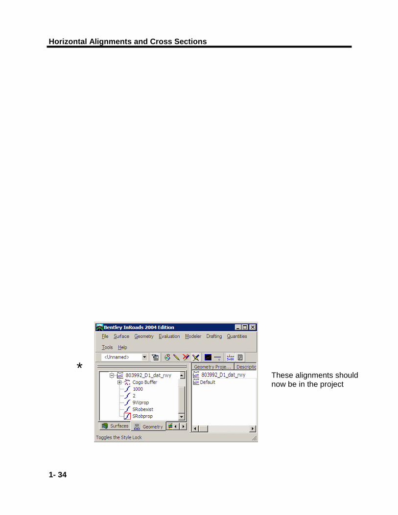
* These alignments should now be in the project
Horizontal Alignments
1- 35
Chapter 1
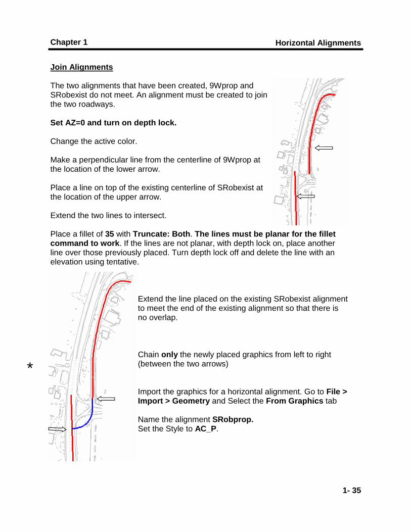
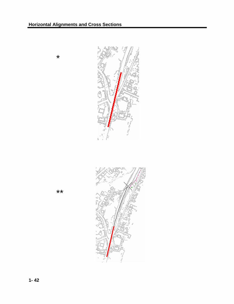
Join Alignments The two alignments that have been created, 9Wprop and SRobexist do not meet. An alignment must be created to join the two roadways. Set AZ=0 and turn on depth lock. Change the active color. Make a perpendicular line from the centerline of 9Wprop at the location of the lower arrow. Place a line on top of the existing centerline of SRobexist at the location of the upper arrow. Extend the two lines to intersect. Place a fillet of 35 with Truncate: Both. The lines must be planar for the fillet command to work. If the lines are not planar, with depth lock on, place another line over those previously placed. Turn depth lock off and delete the line with an elevation using tentative.
Extend the line placed on the existing SRobexist alignment to meet the end of the existing alignment so that there is no overlap. Chain only the newly placed graphics from left to right (between the two arrows) Import the graphics for a horizontal alignment. Go to File > Import > Geometry and Select the From Graphics tab Name the alignment SRobprop. Set the Style to AC_P.
*
Horizontal Alignments and Cross Sections
1- 36
*
Horizontal Alignments
1- 37
Chapter 1
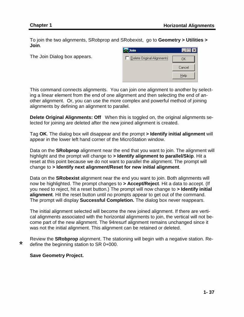
To join the two alignments, SRobprop and SRobexist, go to Geometry > Utilities > Join. The Join Dialog box appears. This command connects alignments. You can join one alignment to another by select-ing a linear element from the end of one alignment and then selecting the end of an-other alignment. Or, you can use the more complex and powerful method of joining alignments by defining an alignment to parallel. Delete Original Alignments: Off When this is toggled on, the original alignments se-lected for joining are deleted after the new joined alignment is created. Tag OK. The dialog box will disappear and the prompt > Identify initial alignment will appear in the lower left hand corner of the MicroStation window. Data on the SRobprop alignment near the end that you want to join. The alignment will highlight and the prompt will change to > Identify alignment to parallel/Skip. Hit a reset at this point because we do not want to parallel the alignment. The prompt will change to > Identify next alignment/Reset for new initial alignment. Data on the SRobexist alignment near the end you want to join. Both alignments will now be highlighted. The prompt changes to > Accept/Reject. Hit a data to accept. (If you need to reject, hit a reset button.) The prompt will now change to > Identify initial alignment. Hit the reset button until no prompts appear to get out of the command. The prompt will display Successful Completion. The dialog box never reappears. The initial alignment selected will become the new joined alignment. If there are verti-cal alignments associated with the horizontal alignments to join, the vertical will not be-come part of the new alignment. The 94resurf alignment remains unchanged since it was not the initial alignment. This alignment can be retained or deleted. Review the SRobprop alignment. The stationing will begin with a negative station. Re-define the beginning station to SR 0+000. Save Geometry Project.
*

Horizontal Alignments and Cross Sections
1- 38
Horizontal Alignments
1- 39
Chapter 1
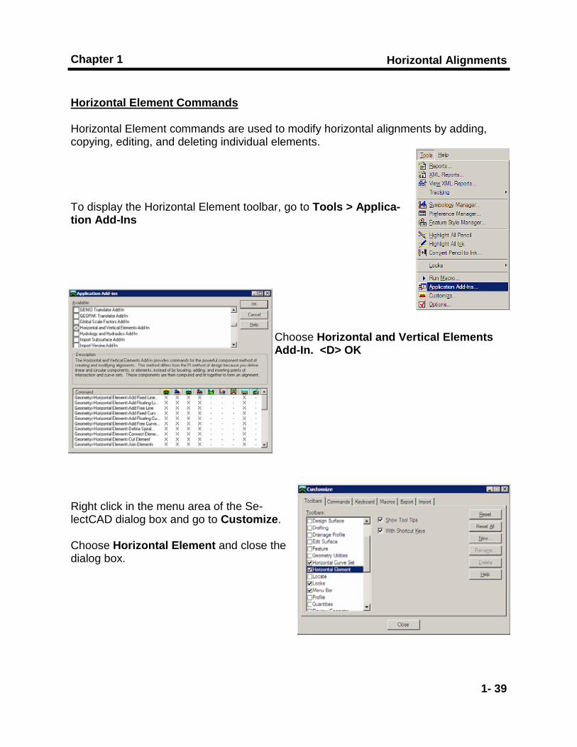
Horizontal Element Commands Horizontal Element commands are used to modify horizontal alignments by adding, copying, editing, and deleting individual elements. To display the Horizontal Element toolbar, go to Tools > Applica-tion Add-Ins
Choose Horizontal and Vertical Elements Add-In. <D> OK
Right click in the menu area of the Se-lectCAD dialog box and go to Customize. Choose Horizontal Element and close the dialog box.

Horizontal Alignments and Cross Sections
1- 40
Horizontal Alignments
1- 41
Chapter 1
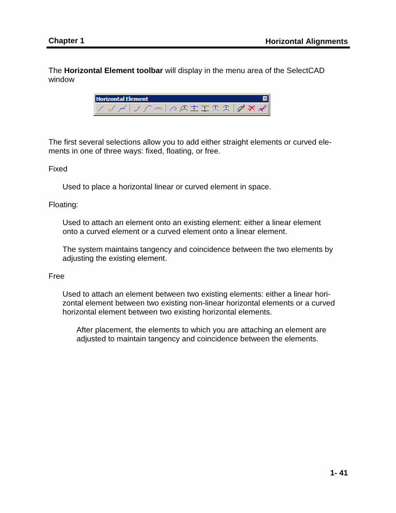
The Horizontal Element toolbar will display in the menu area of the SelectCAD window The first several selections allow you to add either straight elements or curved ele-ments in one of three ways: fixed, floating, or free. Fixed
Used to place a horizontal linear or curved element in space. Floating:
Used to attach an element onto an existing element: either a linear element onto a curved element or a curved element onto a linear element.
The system maintains tangency and coincidence between the two elements by adjusting the existing element.
Free
Used to attach an element between two existing elements: either a linear hori-zontal element between two existing non-linear horizontal elements or a curved horizontal element between two existing horizontal elements.
After placement, the elements to which you are attaching an element are adjusted to maintain tangency and coincidence between the elements.
Horizontal Alignments and Cross Sections
1- 42
*
**
Horizontal Alignments
1- 43
Chapter 1
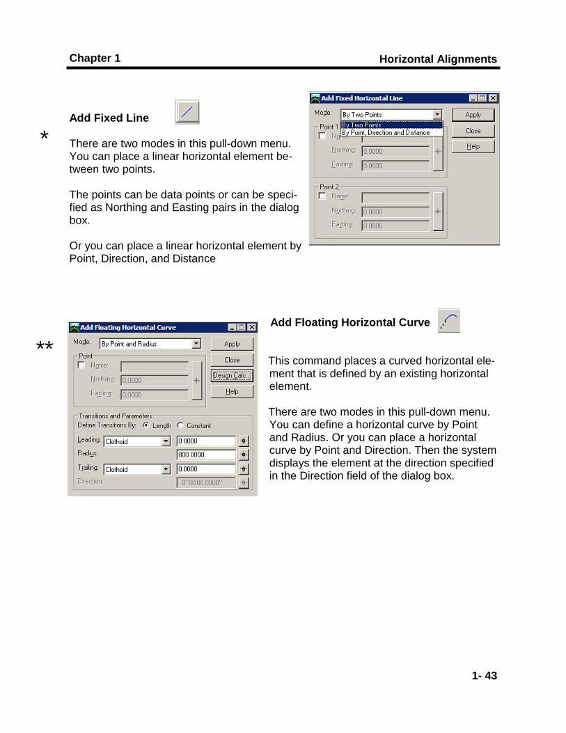
Add Fixed Line There are two modes in this pull-down menu. You can place a linear horizontal element be-tween two points. The points can be data points or can be speci-fied as Northing and Easting pairs in the dialog box. Or you can place a linear horizontal element by Point, Direction, and Distance
Add Floating Horizontal Curve
This command places a curved horizontal ele-ment that is defined by an existing horizontal element.
There are two modes in this pull-down menu. You can define a horizontal curve by Point and Radius. Or you can place a horizontal curve by Point and Direction. Then the system displays the element at the direction specified in the Direction field of the dialog box.
*
**
Horizontal Alignments and Cross Sections
1- 44
*
**
Horizontal Alignments
1- 45
Chapter 1
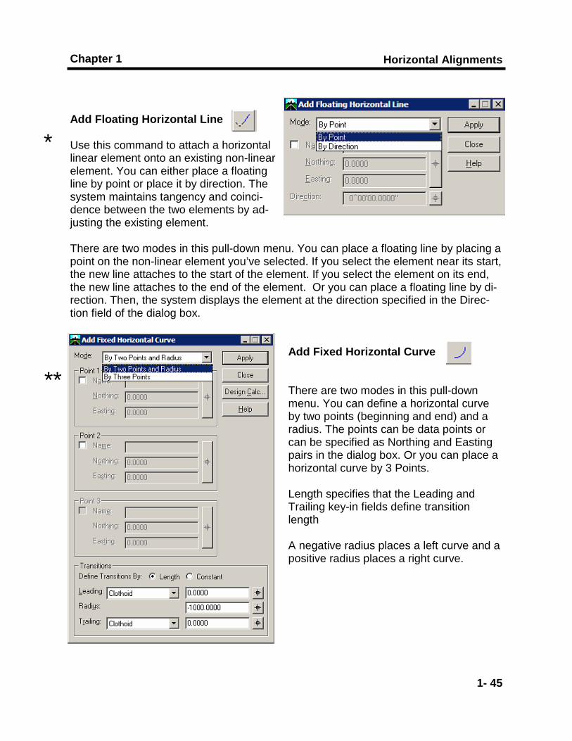
Add Floating Horizontal Line Use this command to attach a horizontal linear element onto an existing non-linear element. You can either place a floating line by point or place it by direction. The system maintains tangency and coinci-dence between the two elements by ad-justing the existing element. There are two modes in this pull-down menu. You can place a floating line by placing a point on the non-linear element you’ve selected. If you select the element near its start, the new line attaches to the start of the element. If you select the element on its end, the new line attaches to the end of the element. Or you can place a floating line by di-rection. Then, the system displays the element at the direction specified in the Direc-tion field of the dialog box.
Add Fixed Horizontal Curve There are two modes in this pull-down menu. You can define a horizontal curve by two points (beginning and end) and a radius. The points can be data points or can be specified as Northing and Easting pairs in the dialog box. Or you can place a horizontal curve by 3 Points. Length specifies that the Leading and Trailing key-in fields define transition length A negative radius places a left curve and a positive radius places a right curve.
*
**
Horizontal Alignments and Cross Sections
1- 46
*
**
Horizontal Alignments
1- 47
Chapter 1
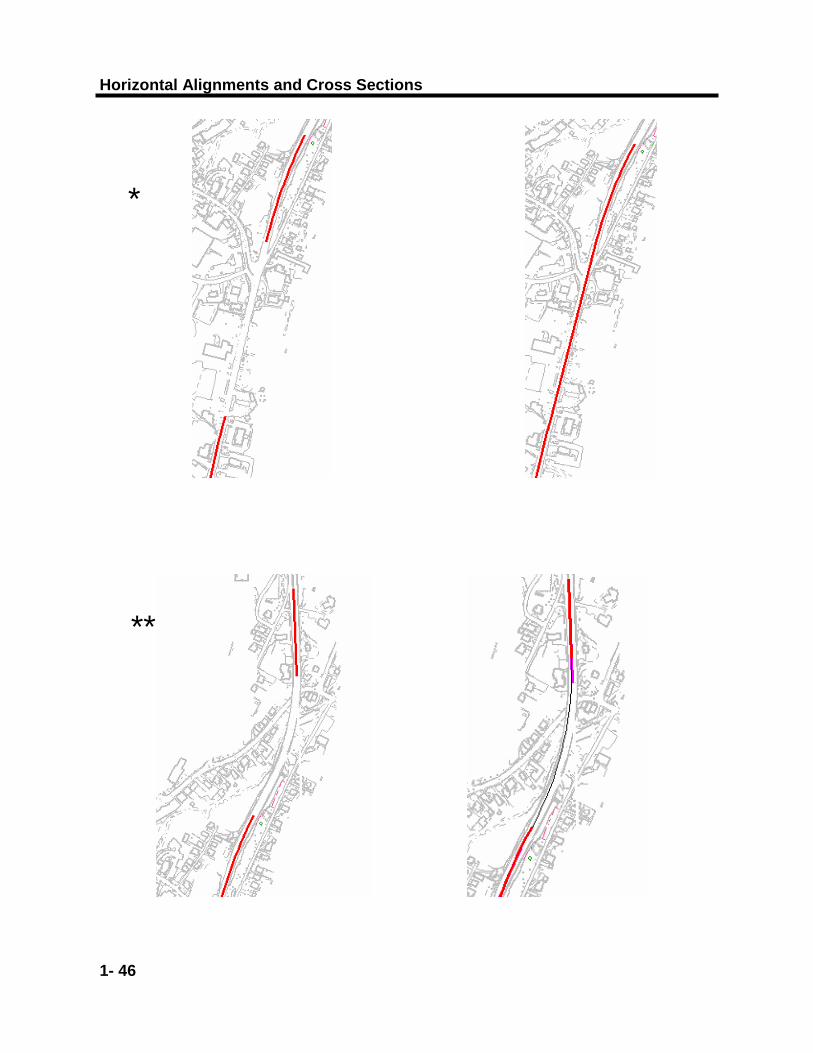
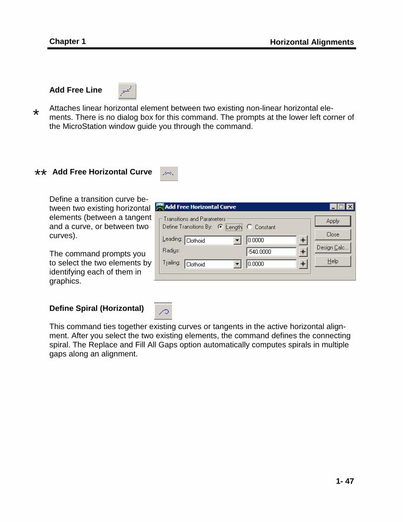
Add Free Line Attaches linear horizontal element between two existing non-linear horizontal ele-ments. There is no dialog box for this command. The prompts at the lower left corner of the MicroStation window guide you through the command. Add Free Horizontal Curve
Define a transition curve be-tween two existing horizontal elements (between a tangent and a curve, or between two curves). The command prompts you to select the two elements by identifying each of them in graphics. Define Spiral (Horizontal) This command ties together existing curves or tangents in the active horizontal align-ment. After you select the two existing elements, the command defines the connecting spiral. The Replace and Fill All Gaps option automatically computes spirals in multiple gaps along an alignment.
*
**
Horizontal Alignments and Cross Sections
1- 48
* Selected end
Selected end
Horizontal Alignments
1- 49
Chapter 1
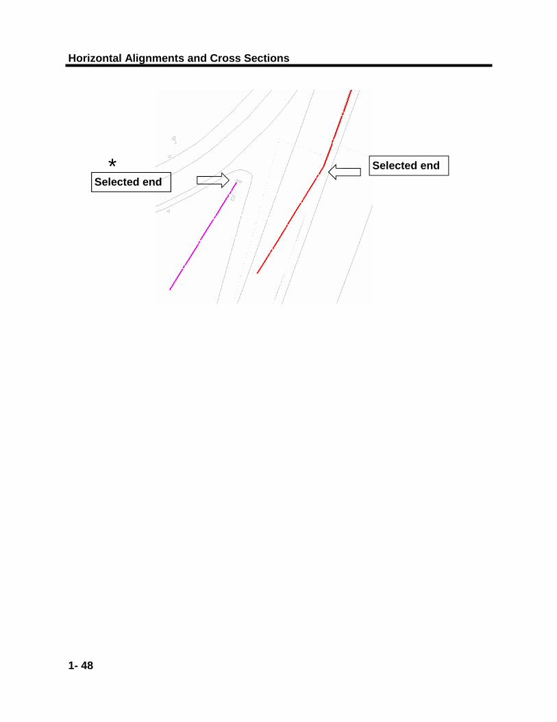
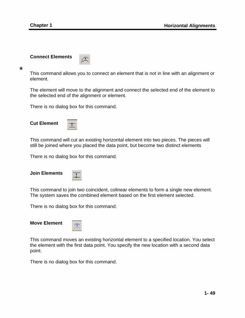
Connect Elements This command allows you to connect an element that is not in line with an alignment or element. The element will move to the alignment and connect the selected end of the element to the selected end of the alignment or element. There is no dialog box for this command. Cut Element This command will cut an existing horizontal element into two pieces. The pieces will still be joined where you placed the data point, but become two distinct elements There is no dialog box for this command. Join Elements This command to join two coincident, colinear elements to form a single new element. The system saves the combined element based on the first element selected. There is no dialog box for this command. Move Element This command moves an existing horizontal element to a specified location. You select the element with the first data point. You specify the new location with a second data point. There is no dialog box for this command.
*

Horizontal Alignments and Cross Sections
1- 50
Horizontal Alignments
1- 51
Chapter 1
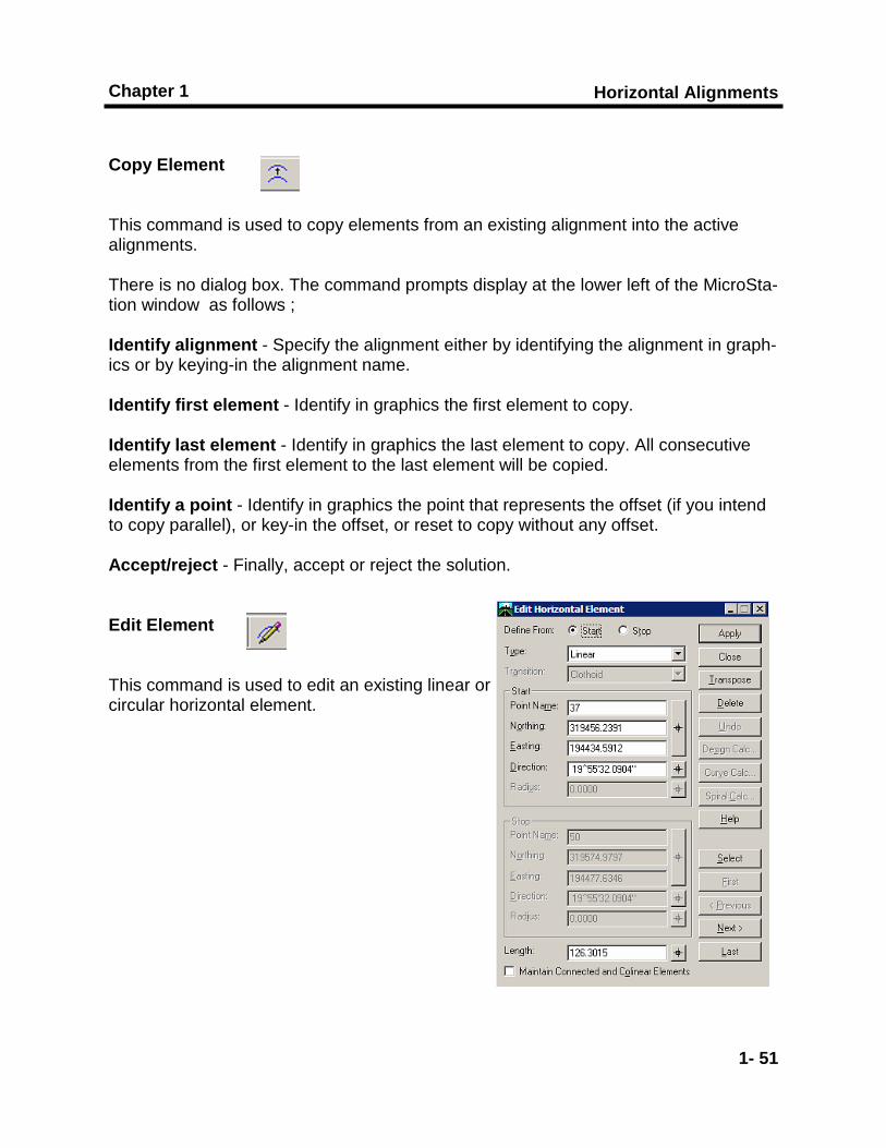
Copy Element This command is used to copy elements from an existing alignment into the active alignments. There is no dialog box. The command prompts display at the lower left of the MicroSta-tion window as follows ; Identify alignment - Specify the alignment either by identifying the alignment in graph-ics or by keying-in the alignment name. Identify first element - Identify in graphics the first element to copy. Identify last element - Identify in graphics the last element to copy. All consecutive elements from the first element to the last element will be copied. Identify a point - Identify in graphics the point that represents the offset (if you intend to copy parallel), or key-in the offset, or reset to copy without any offset. Accept/reject - Finally, accept or reject the solution. Edit Element This command is used to edit an existing linear or circular horizontal element.
Horizontal Alignments and Cross Sections
1- 52
*
Horizontal Alignments
1- 53
Chapter 1
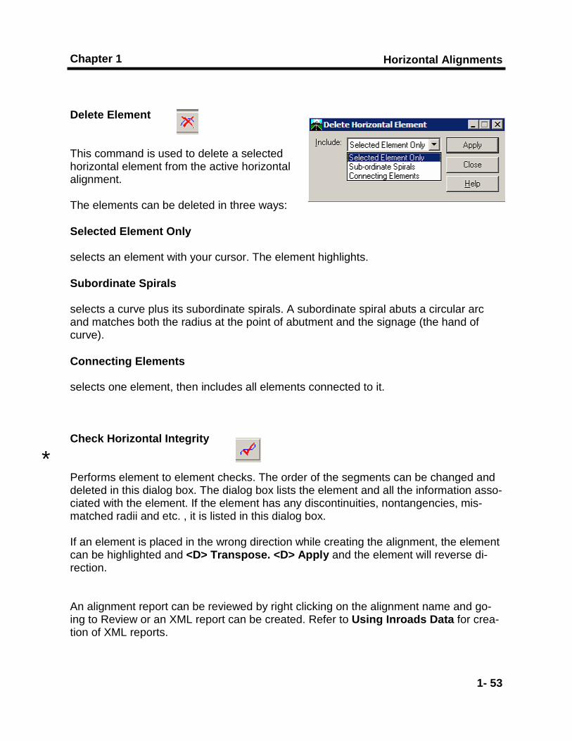
Delete Element This command is used to delete a selected horizontal element from the active horizontal alignment. The elements can be deleted in three ways: Selected Element Only
selects an element with your cursor. The element highlights.
Subordinate Spirals
selects a curve plus its subordinate spirals. A subordinate spiral abuts a circular arc and matches both the radius at the point of abutment and the signage (the hand of curve).
Connecting Elements
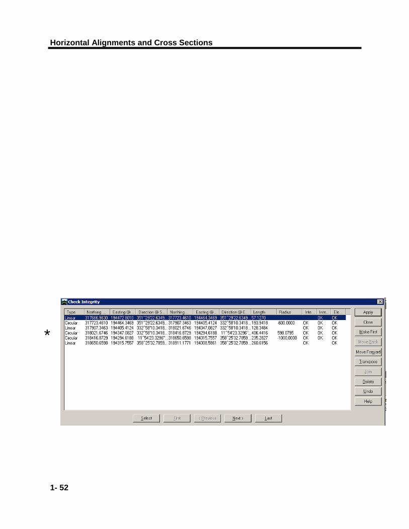
selects one element, then includes all elements connected to it. Check Horizontal Integrity Performs element to element checks. The order of the segments can be changed and deleted in this dialog box. The dialog box lists the element and all the information asso-ciated with the element. If the element has any discontinuities, nontangencies, mis-matched radii and etc. , it is listed in this dialog box. If an element is placed in the wrong direction while creating the alignment, the element can be highlighted and <D> Transpose. <D> Apply and the element will reverse di-rection. An alignment report can be reviewed by right clicking on the alignment name and go-ing to Review or an XML report can be created. Refer to Using Inroads Data for crea-tion of XML reports.
*

Horizontal Alignments and Cross Sections
1- 54
Cross Sections
2- 1
Chapter 2
Chapter 2 Cross Sections
Introduction...
This chapter will display cross sections to check the placement of the alignment and the use of cross section viewer

Horizontal Alignments and Cross Sections
2- 2
Cross Sections
2- 3
Chapter 2
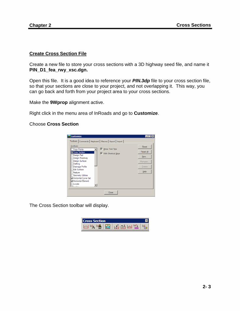
Create Cross Section File Create a new file to store your cross sections with a 3D highway seed file, and name it PIN_D1_fea_rwy_xsc.dgn. Open this file. It is a good idea to reference your PIN.3dp file to your cross section file, so that your sections are close to your project, and not overlapping it. This way, you can go back and forth from your project area to your cross sections. Make the 9Wprop alignment active. Right click in the menu area of InRoads and go to Customize. Choose Cross Section The Cross Section toolbar will display.
Horizontal Alignments and Cross Sections
2- 4
* Refer to the Using InRoads Data training manual for the procedure for dis-playing cross section.
**
Cross Sections
2- 5
Chapter 2
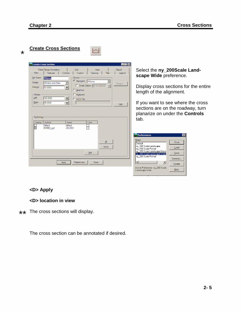
Create Cross Sections
Select the ny_200Scale Land-scape Wide preference.
Display cross sections for the entire length of the alignment. If you want to see where the cross sections are on the roadway, turn planarize on under the Controls tab.
<D> Apply <D> location in view The cross sections will display. The cross section can be annotated if desired.
*
**

Horizontal Alignments and Cross Sections
2- 6
Cross Sections
2- 7
Chapter 2
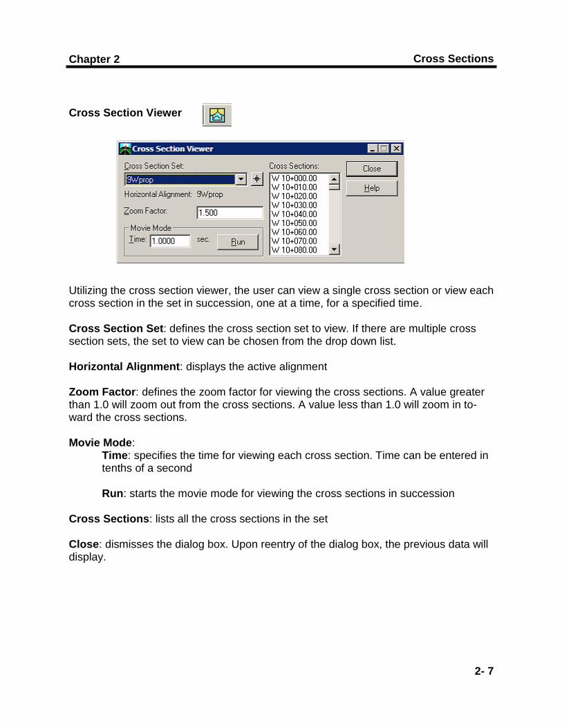
Cross Section Viewer Utilizing the cross section viewer, the user can view a single cross section or view each cross section in the set in succession, one at a time, for a specified time. Cross Section Set: defines the cross section set to view. If there are multiple cross section sets, the set to view can be chosen from the drop down list. Horizontal Alignment: displays the active alignment Zoom Factor: defines the zoom factor for viewing the cross sections. A value greater than 1.0 will zoom out from the cross sections. A value less than 1.0 will zoom in to-ward the cross sections. Movie Mode: Time: specifies the time for viewing each cross section. Time can be entered in tenths of a second Run: starts the movie mode for viewing the cross sections in succession Cross Sections: lists all the cross sections in the set Close: dismisses the dialog box. Upon reentry of the dialog box, the previous data will display.

This page intentionally left blank

End