horizontal air delivery model uhh vertical air delivery...
TRANSCRIPT
Catalog 702
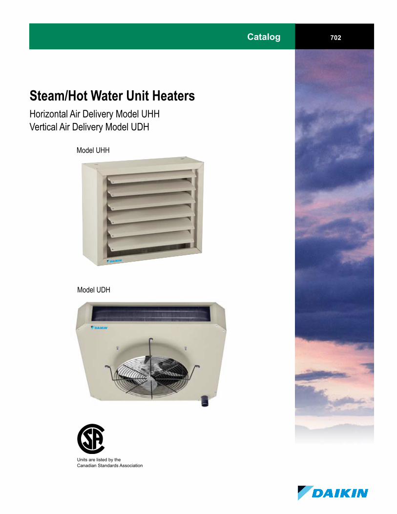
Steam/Hot Water Unit HeatersHorizontal Air Delivery Model UHHVertical Air Delivery Model UDH
Model UHH
Model UDH
Units are listed by the Canadian Standards Association

Catalog 702 / Page 2 of 36
Table of Contents
Design FeaturesHorizontalAirDeliveryModelUHH......................3VerticalAirDeliveryModelUDH..........................4
Dimensional DataHorizontalAirDeliveryModelUHH......................5VerticalAirDeliveryModelUDH..........................6
Performance DataModel UHH
ModelUHHHotWater-HighMotorSpeed..........7ModelUHHHotWater-ReducedMotorSpeed....7ModelUHHSteam-HighMotorSpeed.................8ModelUHHSteam-ReducedMotorSpeed...........8HorizontalModelUHH-MotorData.....................9
Model UDHModelUDHHotWater-HighMotorSpeed........10ModelUDHSteam-HighMotorSpeed...............10VerticalModelUDH-MotorData........................11
Application Guidelines HorizontalAirDeliveryUnitHeaters...................12VerticalAirDeliveryUnitHeaters........................12OtherFactorsThatCanInfluenceSelection..........12SelectionforApplicationsWhereSoundisaFactor..............................................................12BuildingorRoomSoundZones............................12
Locating Unit Heaters ..................................................... 13MonitorTypeBuilding..........................................14MillTypeBuilding................................................14WarehouseBuilding..............................................14Office/ManufacturingBuilding.............................14NarrowBuilding....................................................14
Automatic Control ........................................................... 15
Selection Formulas & Data .......................................... 16- 23Example1: HotWaterCalculation,HorizontalUnit......................................................16HotWaterUnitHeaterMountingHeightCorrectionFactors.................................................16HotWaterCalculationFormulas...........................17
HotWaterHtngCap.ConversionFactors.............18CorrectionFactorsforVaryingWaterTemperatureDrop..................................................18EthyleneGlycolCorrectionFactors......................18Example2:SteamCalculation,HorizontalUnit...19SteamCalculationFormulas.................................20SteamHtngCap.ConversionFactors,HorizontalDelivery...............................................20AirTemperatureRiseConversionFactors,HorizontalDelivery...............................................21PropertiesofSteam...............................................21SteamUnitHeaterMountingHeightCorrectionFactors.................................................21Example3:HotWaterCalculation,VerticalUnit..........................................................22Example4:SteamCalculation,VerticalUnit........22SteamHtngCapacityConversionFactors,VerticalDelivery....................................................23AirTemperatureRiseConversionFactors,VerticalDelivery....................................................23
Motor Data & Power Codes ............................................... 24ModelUHH&UDH.............................................24
Performance Curves ..................................................... 25-28
Options/AccessoriesUnitHeaterFactoryMountedOptions..................29UnitHeaterFieldInstalledOptions.......................29FieldInstalledOptions&AccessoriesforVerticalAirDeliveryModels.......................... 30-31
Piping For Unit Heaters ...................................................... 32
Guide Specifications ..................................................... 33-34HorizontalAirDeliveryModelUHH....................33VerticalAirDeliveryModelUDH........................34
Metric & English Conversion ............................................. 35

Catalog 702 / Page 3 of 36
Design Features
Coil■ Sturdy,mechanicallybondedcopper/aluminum
coilwith12finsperinchwith1/2˝nominaltubes■ HighBtucapacity■ Coilsaretestedat275psigairunderwater.Coils
aresuitableforoperatingupto150psigsteamor220psigwaterand375ºF
■ Finsarecontinuousacrosswidthanddepthofcoilandareverticallyorientedtoresistcollectionofdirtandforeignparticles
Enclosure■ Rugged18-gaugecasingprotectsagainstabuse■ Twopieceenclosureallowsforeaseof
maintenance■ Durableandattractivegraytexturedepoxy
powdercoatingisstandard
Louvers■ Adjustablehorizontallouversarestandardfor
adjustmentofairdistribution■ Constructedofrigid18-gaugesteel■ Colormatchedtoenclosureforconsistent
appearance
Piping Connection■ NPTconnectionspermitquickandeasypiping
withnoadditionalcomponentsneeded■ Mountedtocasingforrigidity
Mounting Hardware■ Heavydutythreadedhardwareallowsunittobe
mountedwiththreadedrod■ Optionalpipehangerkitavailableformounting
unitwiththreadedpipe
Formed Air Inlet/Outlet■ Die-formedventuriinletdrawsairsmoothly
intounitformaximumairflow
Motor■ Allmotorsaretotallyenclosed,permanently
lubricatedforextended,reliablemotorlife■ Lowoperatingcostandquietoperation■ Whenteamedwithvariablespeedcontrol,fan
speedadjustmentisinfinite■ Equippedwiththermaloverloadprotection
Fan■ Lightweightanddynamicallybalanced■ Designedtomoveairefficientlywithminimum
powerrequirement
Finger Proof Fan Guard■ Standardequipmentper(CSA,OSHA)■ Securelymountsmotortounitwhileabsorbing
vibrationwithrubberisolationmounts
Horizontal Air Delivery Model UHH

Catalog 702 / Page � of 36
Design Features
Coil■ Sturdy,mechanicallybondedcopper/aluminum
formedcoilwith12finsperinchwith1/2˝nominaltubesbetweenextra-heavysteelpipeconnections
■ HighBtuCapacity■ Coilsaretestedat275psigairunderwater.Coils
aresuitableforoperatingupto150psigsteamor220psigwaterand375ºF
■ Finsarecontinuousalongwidthanddepthandareverticallyorientedtoresistcollectionofdirtandforeignparticles
Formed Air Inlet/Outlet■ Die-formedventurioutletdrawsairthroughunit
formaximumairflow
Air Diffusion■ Multiplearrangementsavailableforunlimitedair
diffusionpatterns■ Accessoriesarefinishedwithepoxy-based
powdercoatingtomatchunit
Finger Proof Fan Guard■ Standardequipmentper(CSA,OSHA)■ Gives100%safetyconfidenceformountingin
anyarea■ Constructedofpaintedsteelrod
Fan■ Lightweight,dynamicallybalanced■ Designedtomoveairefficientlyandquietlywith
minimumpowerrequirement
Casing■ Rugged16-gaugecasingprotectsagainstabuse■ Separatetopandbottomenclosurepiecesallow
foreaseofmaintenance■ Attractivegraytexturedepoxypowdercoatingis
standardanddurable
Motor■ Allmotorsaretotallyenclosed,permanently
lubricatedforextended,reliablemotorlife■ Lowoperatingcostandquietoperation■ Designedforeasymotorremoval,importantfor
highceilingapplications■ Equippedwiththermaloverloadprotection■ Highefficiency
Mounting Hardware■ Heavydutythreadedhardwareallowsunittobe
mountedwiththreadedrod■ Optionalpipehangerkit(requires2)available
formountingunitwiththreadedpipe
Junction Box■ Allunitwiringiscontainedinanelectrical
junctionboxthatismountedtotheunitheatercasing
Piping Connection■ Durablesteelheaderhasexternal■ NPTthreadsforeasyconnection
Vertical Air Delivery Model UDH

Catalog 702 / Page � of 36
Dimensional Data
Unit Size 18 through 86 Unit Size 108 through 340
Unit Size A B C D E G NPTCONNECTIONS
FAN DIAMETER
APPROX.SHIPPING
WT. LB.
Notes:1. All dimensions in inches.2. UHH-18 through UHH-86 have side NPT female pipe connections.3. UHH-108 through UHH-3�0 have top and bottom NPT male pipe connections.�. Units should be mounted a minimum of �" from wall.
UHH-18UHH-24UHH-33UHH-47UHH-63UHH-86
UHH-108UHH-121UHH-165UHH-193UHH-258UHH-290UHH-340
1�1�1919191927272727333339
16 7/816 7/819 3/�19 3/�2� 3/�2� 3/�2� 7/82� 7/831 7/831 7/8
�0 13/16�0 13/16�0 13/16
7 1/27 1/27 1/27 1/28 1/28 1/29 1/29 1/21010111112
� 1/2� 1/2� 3/�� 3/�� 3/�� 3/�6 1/�6 1/�6 1/�8 3/88 3/88 3/88 3/8
1212121218181818
2� 7/82� 7/832 7/832 7/832 7/8
3 1/23 1/23 1/23 1/23 1/23 1/23 1/23 1/23 1/23 1/23 1/23 1/23 1/2
������
� 1/�� 1/�6 1/�6 1/�6 1/�6 1/�7 1/�
10101�1�1�1�———————
——————2222
2 1/�2 1/�2 1/�
3/� 3/� 3/� 3/� 3/� 3/�
1 1/21 1/21 1/21 1/2
222
99
12121�1�1818202022222�
18193�36�1�276779�96
16�167182
F H J
Table 1. Dimensions – Model UHH
Horizontal Air Delivery Model UHH

Catalog 702 / Page 6 of 36
3-1/�3-1/�3-1.�3-�/83-�/8�-1/2�-1/2�-1/2
13-3/�1�-3/�17-3/�19-3/�21-3/�23-3/�27-3/�29-3/�
232�3�303�3��3�3
1213
1�-7/161920212�27
3-1/83-1/83-1/8
�����
2-3/�2-3/�2-3/�2-3/�2-3/�2-3/�2-3/�2-3/�
Dimensional Data
Unit Size 42, 59 Unit Size 78 through 610
Table 2. Dimensions – Model UDH
UNIT SIZE A B C D E F G MALE NPTCONNECTIONS
FAN DIAMETER
APPROX.SHIPPING
WT. LB.UDH-42, 59UDH-78, 95
UDH-139, 161UDH-193, 212UDH-247, 279UDH-333, 385
UDH-510UDH-610
6-3/86-3/810-3/812-3/812-3/818-3/818-3/818-3/8
1213
1�-7/161718212�27
1�17
18-7/820-7/822-7/82�-3/�28-3/�30-3/�
1-7/81-7/8
222
2-1/22-1/22-1/2
1-1/21-1/21-1/2
22
2-1/22-1/22-1/2
�26�99
1261��189270290
H I
Vertical Air Delivery Model UDH
Note:All dimensions in inches.

Catalog 702 / Page 7 of 36
Performance Data
Horizontal Air Delivery Model UHH (Hot Water)Table 3. Hot Water (High Motor Speed)
Table 4. Hot Water (Reduced Motor Speed)
UnitSize Btu/Hr.
GPM
WATER DATA MOTOR DATA
10,6601�,18620,09027,71638,130�0,7�866,�2073,800109,060127,920
0.�90.830.120.210.�70.790.8�1.0�2.�83.3�
3103�0�90�6�87010�012�01�1�19902310
390��0390����60��0�8�����90680
929898
10�10110�110108111111
91011131�1616171819
131�1618212223262728
IIIIIIIIIIIIIIIIIII
1/301/301/1�1/1�1/101/101/8 1/8 1/� 1/�
UHH-18UHH-24UHH-33UHH-47UHH-63UHH-86
UHH-108UHH-121UHH-165UHH-193
1.31.72.�3.��.76.28.19.013.31�.6
12001200120012001200120087�87�87�87�
PressureDrop
(Ft. of water)SoundClass**
Max.Mounting
Height(ft.)*
HeatSpread@
MaxHeight*
CfmOutlet
VelocityFPM
Final AirTemp. (°F)
HP Approx.RPM
AIR DATA
Btu/Hr. Min./MaxGPM
SoundClass**
Max.Mounting
Height(ft.)*
HeatSpread@
MaxHeight*
CfmOutlet
VelocityFPM
Final AirTemp. (°F)
HPUnitSize Approx.
RPM
WATER DATA MOTOR DATA
13,00017,3002�,�0033,800�6,�0061,90081,00090,000133,0001�6,000198,00022�,000273,000
1.31.72.�3.��.76.28.19.013.31�.619.822.�27.3
0.�90.830.120.210.�70.790.8�1.0�2.�83.3�3.���.��3.2�
0.3/�.00.3/�.00.�/10.00.�/10.00.�/1�.00.�/1�.00.�/20.00.7/20.02.0/30.02.0/30.02.�/�0.02.�/�0.02.�/�0.0
�00��0630730112013�01��0177�2�0029003900�300�130
�00�70�9��80�9071060�69073�8�089�9909��
909696
10398
103108107109110107108109
91011131�1616171819202122
182022263031333638�0�2�6�0
IIIIIIIIIIIIIIIIIIIIIIVIVVVV
1/301/301/1�1/1�1/101/101/8 1/8 1/� 1/� 1/3 1/2 1/2
UHH-18UHH-24UHH-33UHH-47UHH-63UHH-86
UHH-108UHH-121UHH-165UHH-193UHH-258UHH-290UHH-340
HORI
ZONT
AL A
IR D
ELIV
ERY
Model TypeUHH GPM
PressureDrop (Ft. of
water)
AIR DATA
1��01��01��01��01��01��0107�107�107�107�107�107�107�
HORI
ZONT
AL A
IR D
ELIV
ERY
Model TypeUHH
Notes:1. Performance Data at Standard Conditions of 200°F Entering Water, 60°F Entering Air and 20°F Water Temperature Drop.* Units with horizontal louvers open 30° from vertical plane.** See page 12 for Sound Class definitions.

Catalog 702 / Page 8 of 36
Performance Data
Horizontal Air Delivery Model UHH (Steam)Table 5. Steam (High Motor Speed)
Btu/Hr. Sq. Ft.EDR Sound
Class**
Max.Mounting
Height(ft.)*
HeatSpread@
MaxHeight*
CfmOutlet
VelocityFPM
Final AirTemp. (°F)
Condensatelb./hr. HP
UnitSize Approx.
RPM
AIR DATA MOTOR DATA
18,0002�,00033,000�7,00063,00086,000108,000121,00016�,000193,0002�8,000290,0003�0,000
182�3��966891111261702002673003�2
7�1001381962633�8��0�0�68880�107�12081�17
�00��0630730112013�01��0177�2�0029003900�300�130
�10�80�1060060�73062�71�7�0870920
101096�
10210910912011211912�123121122121122121
99
10121�1�1�161718192020
1718202�293132333�37�0���6
IIIIIIIIIIIIIIIIIIIIIIVIVVVV
1/301/301/1�1/1�1/101/101/8 1/8 1/� 1/� 1/3 1/2 1/2
UHH-18UHH-24UHH-33UHH-47UHH-63UHH-86
UHH-108UHH-121UHH-165UHH-193UHH-258UHH-290UHH-340
HORI
ZONT
AL A
IR D
ELIV
ERY
Model TypeUHH
1��01��01��01��01��01��0107�107�107�107�107�11001100
Notes:1. Performance Data at Standard Conditions of 2 lb. Steam and 60°F Entering Air.* Units with horizontal louvers open 30° from vertical plane.** See page 12 for Sound Class definitions.
Table 6. Steam (Reduced Motor Speed)
Btu/Hr. Sq. Ft.EDR Sound
Class**
Max.Mounting
Height(ft.)*
HeatSpread@
MaxHeight*
CfmOutlet
VelocityFPM
Final AirTemp. (°F)
Condensatelb./hr. HP
UnitSize Approx.
RPM
AIR DATA MOTOR DATA
1�,80019,70027,10038,�00�1,70070,�0088,60099,20013�,3001�8,300
1�2129�0��739110313916�
628211316121629�369�13�6�6�9
3103�0�90�6�870
10�012�01�1�19902310
39����39��6��70�70�00�7060069�
10�11211112311�12312612�123123
99
10121�1�1�161718
12131�18212223232�26
IIIIIIIIIIIIIIIIIII
1/301/301/1�1/1�1/101/101/81/81/�1/�
UHH-18UHH-24UHH-33UHH-47UHH-63UHH-86
UHH-108UHH-121UHH-165UHH-193HO
RIZO
NTAL
AIR
DEL
IVER
Y
Model TypeUHH
12001200120012001200120087�87�87�87�

Catalog 702 / Page 9 of 36
�.8/2.3-2.��.8/2.3-2.��.8/2.3-2.��.8/2.3-2.��.8/2.3-2.��.8/2.3-2.�6.8/3.1-3.�6.8/3.1-3.�6.8/3.1-3.�6.8/3.1-3.�7.8/3.6-3.99.6/�.7-�.89.6/�.7-�.8
VOLTAGE, MOTOR TYPE AND POWER CODE115/60/1 230/60/1 230/460/60/3 115/208-230/60/1
Motor HPUnit Size
AAmps
GAmps
IAmps
VAmps
UHH-18UHH-24UHH-33UHH-47UHH-63UHH-86
UHH-108UHH-121UHH-165UHH-193UHH-258UHH-290UHH-340
1/301/301/1�1/1�1/101/101/81/81/�1/�1/31/21/2
0.700.700.720.721.301.301.�81.�82.6�2.7�3.60�.68�.68
0.220.220.�00.�00.�90.�90.800.801.�01.�02.002.202.20
N/AN/AN/AN/A
1.�/0.71.�/0.72.2/1.12.2/1.12.2/1.12.2/1.12.2/1.12.2/1.12.2/1.1
Totally Enclosed w/ Thermal Overload
Totally Enclosed w/ Thermal Overload Totally Enclosed Explosion Proof w/ Thermal
Overload
Performance Data
Horizontal Air Delivery Model UHHTable 7. Motor Data
Power Code A:Motorsare115volt,60Hertz,singlephase,totallyenclosedwithbuilt-inthermaloverloadprotectionandapermanentsplitcapacitortominimizecurrentdraw.
Power Code G:Motorsare230volt,60Hertz,singlephase,totallyenclosedwithbuilt-inthermaloverloadprotectionandapermanentsplitcapacitortominimizecurrentdraw.
Power Code I:Motorsare230/460volt,60Hertz,threephase,totallyenclosedpolyphaseinductiontype.
Power Code V:Motorsare115/208-230volt,60Hertz,singlephase,explosion-proof,totallyenclosedwithbuilt-inthermaloverloadprotectionsplitphasetype.
Explosion proof motorsaresuitableforClassI,GroupC&D;ClassII,GroupsF&G;ClassIII.CanadianStandardAssociation(CSA)require-mentsstatethattheexplosionproofunitsmaynotbeusedwithafluidtemperatureinexcessof329˚Forpressuresgreaterthan87psigandstillmaintaintheirexplosionproofratingforNationalElectricCodeignitiontemperatureratingT3Bforgraindust.ClassI,GroupDMotorsareforoperationsinareascontaininggasoline,petroleum,naphtha,benzene,butane,propane,alcohol,acetone,lacquersolventornaturalgas.ClassII,GroupFmotorsareforoperationsinareascontainingcarbonblack,coalorcokedust.ClassII,GroupGmotorsareforoperationsinareascontainingflour,starchorgraindust.ClassIIImotorsareforoperationsinareascontainingeasilyignitablefibersandflyings.

Catalog 702 / Page 10 of 36
30,�00��,300�8,�0071,000111,000128,8001�2,7001�9,000197,000220,00026�,000308,000�03,000��9,000
3.1�.�6.07.211.313.11�.�16.119.922.226.731.1�0.9�6.3
0.090.180.�30.610.8�1.110.810.981.6�2.011.271.682.322.�2
0.�/10.00.8/1�.01.0/20.01.3/2�.01.0/30.01.3/�0.01.�/�0.02.0/60.02.0/60.02.3/7�.02.8/7�.03.3/7�.03.0/100.06.0/100.0
IIIIIIIIIIIIIIIVIVIVVVVIVIVI
111�1�1718222�2�27313033�039
1519212325303335363938404847
1721232�28333637�0�7�6�960�8
9�011�01��0177�2�0029003900�300�130�80066007860
10790123�0
7769�0990113212811�8816�0180918032037196619282�8723�3
91979699
1031039�96979799979�97
1/101/101/61/61/�1/�1/21/2�/8�/811
1-1/21-1/2
1��01��01��01��0107�107�900
107�900
107�107�11�011�011�0
Vertical Air Delivery Model UDHTable 8. Hot Water (High Motor Speed)
Btu/Hr. Min./MaxGPM
SoundClass**
Max.Mounting
Height(ft.)*
HeatSpread@
MaxHeight*
CfmOutlet
VelocityFPM
Final AirTemp. (°F)
HPUnitSize Approx.
RPM
WATER DATA MOTOR DATAModel TypeUDH GPM
PressureDrop (Ft. of
water)
AIR DATA
UDH-42UDH-59UDH-78UDH-95
UDH-139UDH-161UDH-193UDH-212UDH-247UDH-279UDH-333UDH-385UDH-500UDH-610
VERT
ICAL
AIR
DEL
IVER
Y
Notes:1. Performance Data at Standard Conditions of 200°F Entering Water, 60°F Entering Air and 20°F Water Temperature Drop. * Equipped with cone jet deflector, blades fully opened are shown in bold. Non-bolded mounting height/spread data is for units without deflectors. Please see page 31 for additional outlet accessory performance data.** See page 12 for Sound Class definitions.
1115161719212425273130334040
1518192124283133343737364443
�2,000�9,00078,0009�,000
139,000161,000193,000212,0002�7,000279,000333,00038�,000�00,000610,000
17�2�632�396�7967180�883
102911631388160�20832��2
IIIIIIIIIIIIIIIVIVIVVVVIVIVI
9�011�01��0177�2�0029003900�300�130�80066007860
10790123�0
7799�39921136128�1�9016�31812180�20�0196819302�9023��
10311111011311611�109109107107110106103106
�36181991��1672002192�62883��398�18631
Table 9. Steam (High Motor Speed)
Btu/Hr. Sq. Ft.EDR Sound
Class**
Max.Mounting
Height(ft.)*
HeatSpread@
MaxHeight*
CfmOutlet
VelocityFPM
Final AirTemp. (°F)
Condensatelb./hr. HP
UnitSize Approx.
RPM
AIR DATA MOTOR DATA
UDH-42UDH-59UDH-78UDH-95
UDH-139UDH-161UDH-193UDH-212UDH-247UDH-279UDH-333UDH-385UDH-500UDH-610
VERT
ICAL
AIR
DEL
IVER
Y
Model TypeUDH
11131�161821232�263030303736
1720222�27313�3739�������6��
1113141618212325263030303736
1/101/101/61/61/�1/�1/21/2�/8�/811
1-1/21-1/2
1��01��01��01��0107�107�900
107�900
107�107�11�011�011�0
Notes:1. Performance Data at Standard Conditions of 2 lb. Steam and 60°F Entering Air - High Motor Speed* Equipped with cone jet deflector, blades fully opened are shown in bold. Non-bolded mounting height/spread data is for units without deflectors. Please see page 31 for additional outlet accessory performance data.** See page 12 for Sound Class definitions.
Performance Data

Catalog 702 / Page 11 of 36
Performance Data
�.8/2.3-2.��.8/2.3-2.��.8/2.3-2.��.8/2.3-2.�6.6/3.1-3.36.6/3.1-3.39.6/�.7-�.89.6/�.7-�.89.6/�.7-�.89.6/�.7-�.8
————
VOLTAGE, MOTOR TYPE AND POWER CODE115/60/1 230/60/1 230/460/60/3 115/208-230/60/1
Motor HPUnit Size
AAmps
GAmps
IAmps
VAmps
UDH-42UDH-59UDH-78UDH-95
UDH-139UDH-161UDH-193UDH-212UDH-247UDH-279UDH-333UDH-385UDH-500UDH-610
1/101/101/61/61/�1/�1/21/2�/8�/811
1-1/21-1/2
1.301.302.202.202.7�2.7��.68�.68�.8��.8�8.9�———
0.�90.�91.101.101.�01.�02.202.203.�03.�0�.�0———
1.�/0.71.�/0.71.�/0.71.�/0.72.2/1.12.2/1.12.2/1.12.2/1.1�.2/2.1�.2/2.1�.2/2.1�.2/2.1�.0/2.��.0/2.�
Totally Enclosed w/ Thermal Overload
Totally Enclosed w/ Thermal Overload Totally Enclosed Explosion Proof w/ Thermal
Overload
Vertical Air Delivery Model UDH Table 10. Motor Data
Power Code A:Motorsare115volt,60Hertz,singlephase,totallyenclosedwithbuilt-inthermaloverloadprotectionandapermanentsplitcapacitortominimizecurrentdraw.
Power Code G:Motorsare230volt,60Hertz,singlephase,totallyenclosedwithbuilt-inthermaloverloadprotectionandapermanentsplitcapacitortominimizecurrentdraw.
Power Code I:Motorsare230/460volt,60Hertz,threephase,totallyenclosedpolyphaseinductiontype.
Power Code V:Motorsare115/208-230volt,60Hertz,singlephase,explosion-proof,totallyenclosedwithbuilt-inthermaloverloadprotectionsplitphasetype.
Explosion proof motorsaresuitableforClassI,GroupC&D;ClassII,GroupsF&G;ClassIII.CanadianStandardAssociation(CSA)require-mentsstatethattheexplosionproofunitsmaynotbeusedwithafluidtemperatureinexcessof329˚Forpressuresgreaterthan87psigandstillmaintaintheirexplosionproofratingforNationalElectricCodeignitiontemperatureratingT3Bforgraindust.ClassI,GroupDMotorsareforoperationsinareascontaininggasoline,petroleum,naphtha,benzene,butane,propane,alcohol,acetone,lacquersolventornaturalgas.ClassII,GroupFmotorsareforoperationsinareascontainingcarbonblack,coalorcokedust.ClassII,GroupGmotorsareforoperationsinareascontainingflour,starchorgraindust.ClassIIImotorsareforoperationsinareascontainingeasilyignitablefibersandflyings.

Catalog 702 / Page 12 of 36
Application Guidelines for heat loss calculations should reference the ASHRAE Guide or other recognized HVAC engineering publication (or other authoritative source). Essential engineering data should include design conditions for the following:
• BTU requirements• CFM• Final air temperature• Steam or hot water applications• Building type (architectural special needs, if any)• Location and spacing of units• Mounting heights• Heat throw or air diffusion• Sound classifications
Horizontal Delivery Unit HeatersCharacterizedbyitshorizontalairdelivery,thisunitheateriswidelyusedforgeneralindustrialandcommer-cialheating.Horizontallypositionedlouvers(standard)attachedtotheair-dischargesideoftheunitcanbead-justedtolengthenorshortenheatthrowand/ordecreaseorincreasethemountingheight.Adjustableverticallou-vers(optional)whenusedincombinationwithhorizontallouverspermitcompletedirectionalcontrolofheatedair.
Vertical Delivery Unit HeatersDuetotheirdirectlydownwardairdischarge,verticalunitsareparticularlydesirableforheatingareaswithhighceilingsandwherecranewaysandotherobstruc-tionsdictatehighermountingofheatingequipment.Fourairdistributiondevicesprovidingdistinctivelydifferentheat-throwpatternsareofferedtomeetspecificheat-throwandheat-spreadrequirements(seeVerticalAirOutletOptionspage30).
Other Factors Which Can Influence SelectionWhereitisnecessarytomountunitslow,selectmod-elswithlowercfmratingsasthegreatervolumesofairhandledbylargerunitscancreateexcessiveairmove-mentwhenmountedlow.Betterairdistributionandeconomyofheating-systemoperationisrealizedwhenagreaternumberofsmallerunitheatersareusedinsteadofafewernumberoflargerunits.Soundratingsofcertainmodelsmaylimittheiruseforcertainapplications.Insuchinstances,selectunitsbysizesuchthatthetotalnumberofunitsmeettheheatlossandsoundcriteria.CanadianStandardsAssociation(CSA)requirementsstatethatexplosion-proofunitsmaynotbeusedwithafluidtemperatureinexcessof329°For87psiandstillmaintaintheirexplosion-proofrating.
Application Guidelines
Selection for Applications Where Sound is a FactorWhereverfansandmotorsareusedtomoveair,soundisgenerated.Such,ofcourse,isthecasewithunitheaters.Soundemissionsofacertainlargeunitheatermodelmaylimititsuseinapplicationswheresoundlevelrequire-mentsmaybecritical.Insuchinstances,smallermodelsshouldbeselectedwhichintotalmeettheheat-loadcrite-riaofalargersingleunitheater.Cfmandvelocity(fpm)ratingsaregenerallyindicativeofsoundlevels,i.e.,thehigherthecfmandvelocityratingofaunitheater,thegreaterthesoundemissionsfromtheunit.
Sound Classification:DaikinUnitHeatersaredesignedtominimizesoundcreatedbyairflowandmotoroperationbycarefulcomponentselectionandinletgeometry.TheSoundClassificationlistbelowshowstypicalroomsandtheircorrespondingsoundclassrating.Whenplacedinthepairedroom,theunit’ssoundlevelshouldberelativelycomparabletotheambientsoundlevel.
Building or Room Sound ZonesType of Building or Sound Room Sound Zone Zone Apartments, Class Rooms, Court Rooms, Executive Offices, Hospitals, Libraries, Museums, Residences .........................................................I
General Offices, Hotel Dining Rooms, Private Offices, Recreation Rooms, Show Rooms, Small Stores, Tea Rooms, Upper Floors at Department Stores ............................................ II
Bank Lobbies, Cafeterias, Drug Stores, General Offices, Grocery Stores, Gymnasiums, Main Floors at Department Stores, Public Buildings, Post Offices, Restaurants, Service Stations.................................................III
Factories, Foundries, Garages, Machine Shops, Office Machinery Rooms,Packing Plants, Shipping Platforms, Steel Mills, Stadium Common Areas .............. II-VII
Boiler Works, Forge Shops, Round Houses, Steel Fabricating Shops..........VII

Catalog 702 / Page 13 of 36
Application Guidelines
Locating Unit Heaters1. Alwaysdirectairflowtoregionsofgreatestheatloss.
2. More,smallerunitswillprovidebetterheatdistribu-tionthanfewerlargerunits.
3. Thenumberofunitsuseddependsontheheatthroworheatspreadoftheindividualheaters.Arrangeunitheaterstominimizepipingcosts.
4. Morethananyothersinglefactor,impropermount-ingheightisresponsibleformostunsatisfactoryunitheaterinstallations.Whenheatersaremountedhigherthanrecommended,improperheatdistributionistheresultandcomfortisreduced.
• Mountunitsatthelowestpracticalandallowablelevel.
• Watchfinalairtemperatureonunitsmountedatlowerlevelsorinheavilyoccupiedareastoensurethatairiswarmenoughtoavoidnoticeabledrafts.
5. Itisadvisabletolocateunitheaterssothattheirairstreamsaresubjectedtoaminimumofinterferencefromcolumns,machinery,partitionsandotherobstacles.
6. Unitheatersinstalledinabuildingexposedtoapre-vailingwindshouldbelocatedsoastodirectalargeportionoftheheatedairalongthewindwardsideofthebuilding.
7. Horizontaldeliveryunitheatersshouldbelocatedsothattheairstreamsoftheindividualunitswipetheexposedwallsofthebuildingwitheitherparallelfloworangularflowwithoutblowingdirectlyagainstthewalls.Heatersshouldbespacedsothateachsup-portstheairstreamfromanotherheater.Thissetsupacirculatoryairmovementwhichproducesablanketofwarmairalongthecoldwall.
8. Horizontalunitsshouldbearrangedsotheydonotblowdirectlyatworkers.Theirairstreamsshouldbedirecteddownaisles,intoopenspacesonthefloor,oralongexteriorwallsofthebuilding.
10. Largeexpansesofglassorlargedoorsthatarefrequentlyopenedshouldbecoveredbylong-throwunitheaterssuchaslargehorizontaldeliveryunitheaters.
11. Inbuildingshavinghighceilings,verticaldeliveryunitheatersequippedwiththecorrectair-distribu-tiondevicesarerecommendedtoproducecomfortincentralareasofthesamebuilding.
12. Whenonlyverticaldeliveryheatersareused,theyshouldbelocatedsothatexposedwallsareblanketedwiththewarmairtheydeliver.
13. Severalunitheatersmaybeoperatedbyasinglether-mostat.Inlargeopenspaceswherevariousactivitiesarecarriedon,zonalheatingwillimprovecomfortandgenerallyreducefuelcosts.Unitheatersmayalsobecontrolledindividually,eithermanuallyorbyathermostat.
14. Unitheaterfansmaybeoperatedduringwarmweathertomaintainaircirculation.Ifthisisdesired,unitsshouldbeequippedwithfanswitcheswhentheyareinstalled.
15. Illustrations appearing on page 14 & 15 suggestvarious spacing and arrangements of unit heatersfor providing adequate heating coverage.Properplacementofunitheatersinaspacetobeheatedwillalsosimplifypipingandreduceinstallationcosts.

Catalog 702 / Page 1� of 36
Application Guidelines
Monitor-Type BuildingThisapplicationutilizesbothhorizontalandvertical deliveryunitheaters.Verticalunitslocatedinthecentralhigh-ceilingareaclearthecranewaybelowthem.Horizontalunitsareusedinthelow-ceilingareas.
Mill Type BuildingHereeachhorizontaldeliveryunitheatersupportstheairstreamfromanothertosetupacirculatoryairmove-mentwithinthespacetobeheated.Thisarrangementillustratesthebasicprincipleofunitheaterlocation.
Warehouse BuildingThistypicalaapplicationofhorizontalunitheatersillustratesthemaximumheatcoveragewithaminimumnumberofunits.
Narrow BuildingHeatspreadfromverticalunitssuppliesgoodcoverageoftheentirefloorspaceandblanketswallswithwarmedair.
Office/Manufacturing Building

Catalog 702 / Page 1� of 36
Application Guidelines
Automatic ControlControl SequencesThefollowingcontrolsequencedescriptionsarecommonplaceforsteam/hotwaterhorizontalandverticalairdeliveryunitheaters.
Continuous Fan Operation - Intermittent Hot/Cold Coil - Aroomthermostatcontrolsavalvewhichopenstoallowsteamorhotwatertosupplytheunitandclosestoshutoffthesupplywhenthethermostatissatisfied.Thefanrunscontinuously.
Intermittent Fan Operation - Hot Coil - Aroomthermostatstartsandstopsthemotorwhenathermostatcallsforheat,themotorisenergized.Anaquastatissometimesstrappedtothesupplyorreturnpipingtopre-ventfanoperationwhenheatisnotbeingsuppliedtotheunitheater.Theheatingfluidiscontinuouslysuppliedtotheunitheaterevenwiththemotoroff.Afterthermostatissatisfied,motorisde-engergized.
Intermittent Fan Operation - Intermittent Hot/Cold Coil - Topreventaunitheaterfromdeliver-ingcoldairwhenthethermostatis“callingfor”heat,anaquastatpreventsfanoperationwhentheheatsupplytothecoilisinterrupted.Conversely,theaquastatenergizesthefanwhentheautomaticsupplyvalveopenstoallowtheheatingmediumtoentertheunitheatercoil.
Energy Saver – Optional ControlAn“EnergyStar”controlusedwithverticalairdeliveryunitheaterscanautomaticallydeliverwarmstratifiedairtothezoneofoccupancy,minimizeceilingheatlossandoverallenergyconsumption.Twothermostatsandanauxiliaryswitcharerequiredforoneormoreunitheat-ers,plusatwo-positionsupplyvalveforeachunitheater.Theroomthermostatcontrolsthetwo-positionsupplyvalvetoeachunitheater.Anauxiliaryfanswitchstopstheunitheaterfanwhenthesupplyvalveisclosed.Theotherthermostat(“EnergySaver”Control)islocatedneartheverticalunitheaterattheceilingorroofwherewarmairtendstostratify.
Theroomthermostatwillautomaticallysignalthesupplyvalvetoclosewhenitssettinghasbeen“satisfied,”How-ever,thethermostatmountedneartheunitheatercanoverridetheauxiliaryswitchtoallowtheunitheaterfantorunwiththesupplyvalveclosed,untilthetemperatureatthehigherlevelfallsbelowtheset-pointofthehighermountedthermostat.
Additionally,airdeliveredbyaverticalunitheaterlocatedinhighambienttemperaturesprevalentattheupperlevelswithinabuildingisexcessivelybuoyantandfrequentlypreventstheunitheaterfanfromdeliveringtheheatedairtotheoccupancylevelofthebuilding.Byrecyclingtheheatwhichbuildsupatthesehigherlevels,thetwo-thermostatcontrolarrangementcontributestoincreasedcomfortandlowerheatingcosts.
Catalog 702 / Page 16 of 36
Selection Formulas & Data
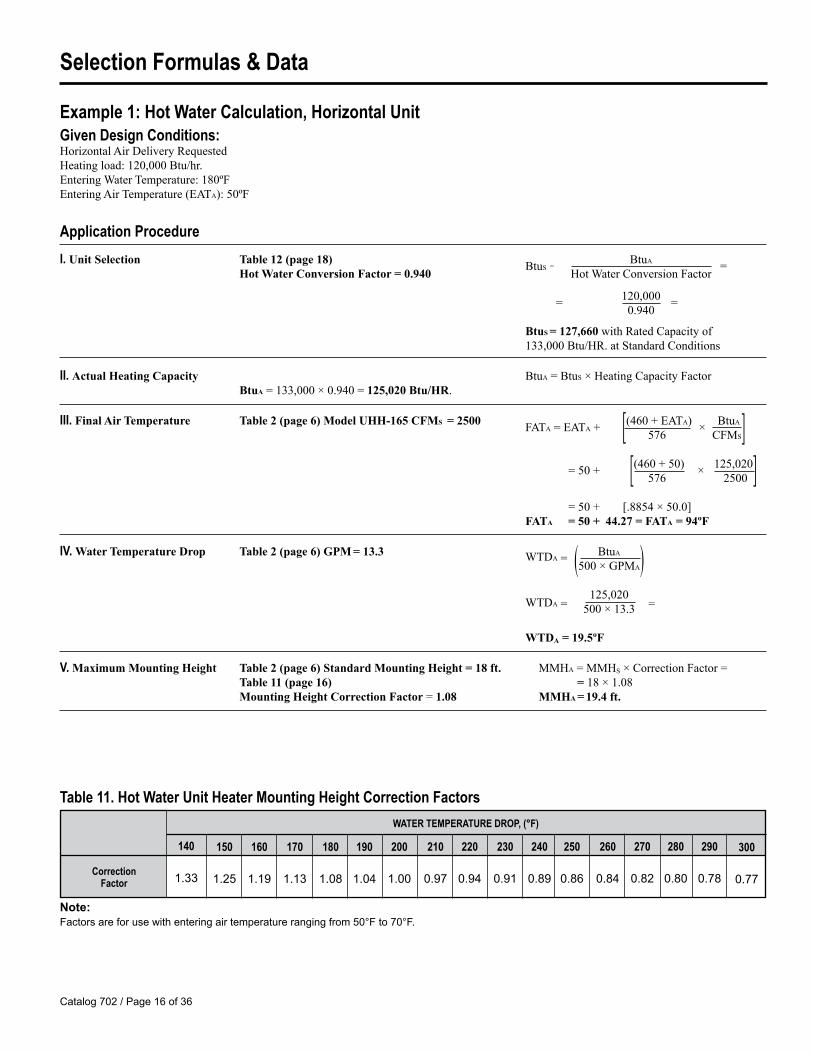
Example 1: Hot Water Calculation, Horizontal Unit Given Design Conditions:HorizontalAirDeliveryRequestedHeatingload:120,000Btu/hr.EnteringWaterTemperature:180ºFEnteringAirTemperature(EATA):50ºF
Application ProcedureI. Unit Selection Table 12 (page 18) BtuS
= BtuA =Hot Water Conversion Factor = 0.940 HotWaterConversionFactor
= 120,000 =0.940
BtuS = 127,660withRatedCapacityof133,000Btu/HR.atStandardConditions
II. Actual Heating Capacity BtuA=BtuS×HeatingCapacityFactorBtuA=133,000×0.940=125,020 Btu/HR.
III. Final Air Temperature Table 2 (page 6)Model UHH-165 CFMS = 2500 FATA=EATA+ [(460+EATA) × BtuA 576 CFMS]
=50+ [(460+50) × 125,020] 576 2500
=50+ [.8854×50.0]FATA = 50 + 44.27 = FATA = 94ºF
IV. Water Temperature Drop Table 2 (page 6) GPM = 13.3 WTDA = BtuA
(500×GPMA)WTDA =
125,020 500×13.3 =
WTDA = 19.5ºF
V. Maximum Mounting Height Table 2 (page 6) Standard Mounting Height = 18 ft. MMHA=MMHS×CorrectionFactor=Table 11 (page 16) = 18×1.08Mounting Height Correction Factor=1.08 MMHA = 19.4 ft.
Table 11. Hot Water Unit Heater Mounting Height Correction Factors
Note:Factors are for use with entering air temperature ranging from �0°F to 70°F.
WATER TEMPERATURE DROP, (°F)
Correction Factor
150
1.2�
160
1.19
170
1.13
180
1.08
190
1.0�
200
1.00
210
0.97
220
0.9�
230
0.91
240
0.89
250
0.86
260
0.8�
270
0.82
280
0.80
290
0.78
300
0.77
140
1.33
Catalog 702 / Page 17 of 36
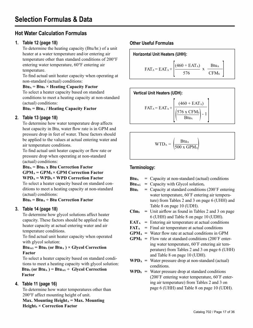
Other Useful Formulas
Horizontal Unit Heaters (UHH):
FATA=EATA+ [ ]
Vertical Unit Heaters (UDH):
FATA=EATA+ [ ]
Terminology:
BtuA = Capacityatnon-standard(actual)conditionsBtuAG = CapacitywithGlycolsolution.BtuS = Capacityatstandardconditions(200˚Fentering
watertemperature,60˚Fenteringairtempera-ture)fromTables2and3onpage6(UHH)andTable8onpage10(UDH).
CfmS = UnitairflowasfoundinTables2and3onpage6(UHH)andTable8onpage10(UDH).
EATA = EnteringairtemperatureatactualconditionsFATA = FinalairtemperatureatactualconditionsGPMA = WaterflowrateatactualconditionsinGPMGPMS = Flowrateatstandardconditions(200˚Fenter-
ingwatertemperature,60˚Fenteringairtem-perature)fromTables2and3onpage6(UHH)andTable8onpage10(UDH).
WPDA = Waterpressuredropatnon-standard(actual)conditions.
WPDS = Waterpressuredropatstandardconditions(200˚Fenteringwatertemperature,60˚Fenter-ingairtemperature)fromTables2and3onpage6(UHH)andTable8onpage10(UDH).
1. Table 12 (page 18)Todeterminetheheatingcapacity(Btu/hr.)ofaunitheateratawatertemperatureand/orenteringairtemperatureotherthanstandardconditionsof200°Fenteringwatertemperature,60°Fenteringairtemperature.Tofindactualunitheatercapacitywhenoperatingatnon-standard(actual)conditions:BtuA = BtuS × Heating Capacity FactorToselectaheatercapacitybasedonstandardconditionstomeetaheatingcapacityatnon-standard(actual)conditions:BtuS = BtuA / Heating Capacity Factor
2. Table 13 (page 18)TodeterminehowwatertemperaturedropaffectsheatcapacityinBtu,waterflowrateisinGPMandpressuredropinfeetofwater.Thesefactorsshouldbeappliedtothevaluesatactualenteringwaterandairtemperatureconditions.Tofindactualunitheatercapacityorflowrateorpressuredropwhenoperatingatnon-standard(actual)conditions:BtuA = BtuS x Btu Correction FactorGPMA = GPMS × GPM Correction FactorWPDA = WPDS × WPD Correction FactorToselectaheatercapacitybasedonstandardcon-ditionstomeetaheatingcapacityatnon-standard(actual)conditions:BtuS = BtuA ÷ Btu Correction Factor
3. Table 14 (page 18)Todeterminehowglycolsolutionsaffectheatercapacity.Thesefactorsshouldbeappliedtotheheatercapacityatactualenteringwaterandairtemperatureconditions.Tofindactualunitheatercapacitywhenoperatedwithglycolsolution:BtuAG = BtuS (or BtuA ) × Glycol CorrectionFactorToselectaheatercapacitybasedonstandardcondi-tionstomeetaheatingcapacitywithglycolsolution:BtuS (or BtuA ) = BtuAG ÷ Glycol CorrectionFactor
4. Table 11 (page 16)Todeterminehowwatertemperaturesotherthan200°Faffectmountingheightofunit.Max. Mounting HeightA = Max. MountingHeightS × Correction Factor
(460+EATA)x
BtuA
576 CFMS
(576xCFMS)-1
BtuA
(460+EATA)
WTDA= ( BtuA )500xGPMA
Hot Water Calculation Formulas
Selection Formulas & Data

Catalog 702 / Page 18 of 36
5
1.23
�.6�
17.2�
To obtain Btu for other Water Temperature Drops, multiply basic Btu rating by applicable Factor.
To obtain GPM for other Water Temperature Drops,multiply basic GPM rating by applicable Factor.
To obtain Pressure Loss Feet of Water for other Tempera-ture Drops, multiply Basic Loss at 20° drop by Factor.
ENTERING WATER TEMPERATURE, °F
100110120130140150160170180190200210220230240250260270280290300
0.0000.0680.1370.20�0.2730.3�20.�100.�780.��70.61�0.68�0.7�20.8200.8890.9�71.02�1.09�1.1621.2301.3001.367
0.6830.7�90.83�0.9110.9871.0631.1391.21�1.2911.3671.��31.�191.�9�1.6701.7�61.8221.8981.97�2.0�02.1262.202
0.�180.�920.6660.7�00.81�0.8880.9621.0361.1101.18�1.2�81.3321.�061.�801.���1.6281.7021.7761.8�01.92�1.998
0.3610.�3�0.�060.�780.6�10.7230.79�0.8670.9�01.0121.08�1.1�71.2291.3011.3731.��61.�181.�901.6631.73�1.807
0.2120.2830.3�30.�2�0.�9�0.�6�0.6360.7060.7770.8�80.9180.9891.0601.1301.2011.2721.3�21.�131.�831.���1.62�
0.0690.1380.2070.2760.3��0.�1�0.�830.��20.6210.6900.7�90.8280.8970.9661.03�1.10�1.1731.2�21.3111.3801.��9
Table 12 – Hot Water Heating Capacity Conversion Factors
0 10 20 30 40 50 60 70 80 90
EnteringWater Temp.
(°F) 1000.7690.8�60.9231.0001.0771.1��1.2311.3081.38�1.�921.�391.61�1.9621.7691.8�61.9232.0002.0772.1��2.2312.308
0.�990.67�0.7�90.82�0.8990.97�1.0�91.12�1.1991.27�1.3�91.�2�1.�991.�731.6�91.7231.7981.8731.9�82.0232.098
0.�390.�120.�8�0.6�80.7310.80�0.8780.9�01.02�1.0971.1701.2�31.3121.3901.�631.�361.6091.6821.7��1.8291.902
0.2860.3�70.�290.�000.�710.6�30.71�0.7860.8�70.9291.0001.0711.1�31.2�11.2861.3�71.�291.�001.�711.6�31.71�
0.1�00.2100.2790.3�90.�190.�890.��90.6290.6990.7680.8380.9080.9781.0�81.1181.1881.2�71.3271.3971.�671.�37
USE FACTORS FROM THIS TABLE TO OBTAINAPPROXIMATE RESULTS 10
1.13
2.21
�.32
15
1.06
1.�0
1.8�
20
1.00
1.00
1.00
25
0.9�
0.76
0.61
30
0.90
0.61
0.�1
35
0.86
0.�0
0.30
40
0.82
0.�2
0.22
45
0.78
0.36
0.18
50
0.72
0.30
0.1�
55
0.69
0.26
0.12
60
0.67
0.23
0.11
Table 13. Correction Factors for Varying Water Temperature Drop (See Note)
Note:Water temperature drop correction factors valid only for standard 200°F entering water and 60°F air temperature conditions.
Entering Air Temperature, (°F)
Table 14. Ethylene Glycol Correction Factors
Note:For Propylene Glycol solution correction factor, multiply Ethylene Glycol correction factor by 0.9�.
ETHYLENE GLYCOL SOLUTION %SolutionTemperature (°F)
100150200
250
30%0.960.960.970.96
40%0.930.9�0.9�0.9�
50%0.890.900.920.92
60%0.8�0.870.880.89
70%0.810.830.8�0.86
20%0.990.990.990.98
80%0.760.780.810.82
Selection Formulas & Data

Catalog 702 / Page 19 of 36
Application Procedure
I. Capacity -atstandardconditions 2lbs.Steam,60ºEnteringAir(EATS). Table 4 (page 7)BtuS = 63,000 Btu/HR.
Capacity -atnon-standardconditions Table 15 (page 20)Heating Capacity Factor = 1.0610lbs.Steam,70ºEnteringAir(EATA). BtuA=BtuS×HeatingCapacityFactor=63,000×1.06=BtuA = 66,780 Btu/HR.
II. Final Air Temperature Table 4 (page 7) FATS = 112ºFAirTempRiseCalculations ATRA=(FTAS-EATS)×AirTempRiseFactor(Table 21-1.)=(112ºF-60ºF)×1.07=ATRA = 55.64ºF
FATACalculations FATA=(EATA+ATRA)=70ºF+55.64ºF=FATA = 125.64ºF
II. Final Air Temperature Table 4 (page 7) CFM = 1120FATACalculations
FATA= (BtuA)
+ EATA =66,780
+70ºF=55ºF+70ºF=FATA = 125ºF
1.085×CFM 1.085×1120 (Comparedto125.64ºFinMethodA)
III.Condensate -atstandardconditions Table 4 (page 7)Standard Conditions =66 LB./HR.
Condensate(A) Table 17 (page 21)Latent Heat of Steam = 952.5
Condensate= BtuA 66,780 LatentHeatofSteam= 952.5
= 70.11 LB./HR.
Condensate(B): BtuA (EquivalentDirect) 66,780240
=EDR Radiation=
240= 278.5
EDR 278.5Condensate =4
=4
= 69.56 LB./HR.
IV. Final Air Volume-atstandardconditions Table 4 (page 7)Final Air Temp. FATS = 112ºF, Nominal Cfm = 11202lbs.steam,60ºFEnteringAir(EATS)
Final AV = (460+FATS)×Cfm=(460+112) × 1120=1.08×1120=1210 Cfm530 530
V. Final Air Volume10lbs.steam,70ºFEnteringAir(EATA) Final AV = (460+FATA)×Cfm=(460+125.64)×1120=1.10×1120=1232 Cfm530 530
VI. Maximum Mounting Height Table 4 (page 7) Max. Mounting Height = 14 ft.Table 18 (page 21) Mounting Height Correction Factor = 0.94MMHA=MMHS×CorrectionFactor=14×0.94=MMHA = 13.16 ft.
Example 2: Steam Calculation, Horizontal UnitGiven Design Conditions:UnitHeaterModel:UHH-63SteamPressure:10lbs.EnteringAirTemperature(EATA):70ºF
Meth
od A
Meth
od B
Selection Formulas & Data

Catalog 702 / Page 20 of 36
Steam Calculation Formulas1. Table 15
Todeterminetheheatingcapacity(Btu/hr.)ofaunitheateratasteampressureand/orenteringairtemperatureotherthanstandardconditionsof2lb.Steamand60°Fenteringairtemperature.
Tofindactualunitheatercapacitywhenoperatingatnon-standard(actual)conditions:BtuA = BtuS × Heating Capacity Factor
Toselectaheatercapacitybasedonstandardcon-ditionstomeetaheatingcapacityatnon-standard(actual)conditions:BtuS = BtuA ÷ Heating Capacity Factor
2. Table 16 (page 21)Todeterminetheairtemperatureriseofaunitheateratasteampressureand/orenteringairtemperatureotherthanstandardconditionsof2lb.Steam,60°Fenteringairtemperature.
Tofindactualairtemperatureriseofunitheaterwhenoperatingatnon-standard(actual)conditions:ATRA = (FATS - EATS) × Air Temperature RiseFactor
Tofindactualfinalairtemperatureofunitheaterwhenoperatingatnon-standard(actual)conditions:FATA = EATA + ATRA
3. Table 18 (page 21)Todeterminehownon-standardsteampressures(otherthan2lb.)affectmountingheight.Max. Mounting HeightA = Max. MountingHeightS × Correction Factor
4. Table 17 (page 21)Todeterminetherateofcondensateproductionatsteampressuresotherthan2lb.Condensate Rate = BtuA ÷ Latent Heat of Steam
5. Btu ÷ 240 = EDR (Equivalent Direct Radiation)
6. EDR ÷ 4 = LBS./HR. Condensate
7. ATRA =BtuA(Cfm x 1.085)
TerminologyATRA = Airtemperatureriseatnon-standard(actual)
conditionsBtuA = CapacityatactualoperatingconditionsBtuS = Capacityatstandardconditions(2lb.Steam,
60°Fenteringairtemperature)fromTables4and5onpage7
EATA = Enteringairtemperatureatnon-standard(actual)conditions
EATS = Enteringairtemperatureatstandardconditions(60°F)
FATA = Finalairtemperatureatnon-standard(actual)conditions
FATS = FinalairtemperatureatstandardconditionsfromTables4and5onpage7
Max. Mounting HeightA = Maximummountingheightatactualconditions
Max. Mounting HeightS = Maximummountingheightatstandardconditions
-100102030�0�060708090100
STEAM PRESSURE (PSIG)0 2 5 10 15 20 30 40 50 60 70 75 80 90 100 125 150
Entering Air
Temp. (°F)1.��1.��1.371.271.191.111.030.960.880.810.7�0.67
1.�91.�01.�11.321.2�1.161.081.000.930.8�0.780.71
1.6�1.��1.�61.371.291.211.131.0�0.970.900.830.76
1.731.6�1.��1.�61.381.291.211.131.060.980.910.8�
1.801.711.611.�31.��1.3�1.281.191.121.0�0.970.90
1.861.771.681.�81.�01.�21.331.2�1.171.101.020.9�
1.971.871.781.681.601.�11.�31.3�1.271.191.121.0�
2.061.961.861.771.681.601.�11.�31.3�1.271.191.12
2.132.0�1.9�1.8�1.761.671.�81.�01.�21.3�1.261.19
2.202.092.001.901.811.731.6�1.�61.�71.391.311.2�
2.262.162.061.961.871.781.701.611.�31.��1.371.29
2.282.182.091.991.901.811.721.6�1.��1.�71.�01.32
2.312.212.112.021.931.8�1.7�1.661.�81.�01.�21.3�
2.362.262.162.061.971.881.791.711.621.��1.�61.38
2.�12.312.202.112.021.931.8�1.7�1.661.�81.�01.�2
2.�12.�12.312.212.112.021.931.8�1.761.681.�91.�1
2.602.�02.�02.302.202.112.021.931.8�1.761.671.�9
HORI
ZONT
AL D
ELIV
ERY
ModelUHH
Table 15. - Steam Heating Capacity Conversion Factors, Horizontal Delivery
Selection Formulas & Data

Catalog 702 / Page 21 of 36
-100102030�0�060708090100
STEAM PRESSURE (PSIG)0 2 5 10 15 20 30 40 50 60 70 75 80 90 100 125 150
Entering Air
Temp. (°F)1.331.281.2�1.171.121.071.010.960.900.8�0.780.72
1.381.331.271.221.171.111.061.000.9�0.880.830.76
1.�31.381.331.271.211.161.111.0�1.000.930.880.82
1.�01.��1.�01.3�1.291.2�1.191.131.071.020.9�0.90
1.�61.�11.�61.�21.361.101.2�1.191.1�1.081.020.97
1.611.�61.�21.�61.�11.361.301.2�1.191.1�1.081.02
1.701.6�1.601.��1.�11.�61.�01.3�1.291.2�1.181.12
1.781.731.681.621.�81.��1.�81.�31.381.321.261.21
1.8�1.791.7�1.691.6�1.601.��1.�01.��1.391.331.28
1.911.861.811.7�1.711.661.611.�61.�01.��1.�01.33
1.9�1.911.861.811.761.711.661.611.�61.�11.��1.39
1.971.931.891.8�1.791.7�1.691.6�1.�81.�31.�71.�2
2.001.9�1.911.861.821.761.721.661.611.�61.�91.��
2.0�2.001.9�1.901.861.811.7�1.701.6�1.601.��1.�9
2.082.0�1.991.9�1.891.8�1.791.7�1.691.6�1.�91.�3
2.172.132.092.0�1.991.9�1.891.8�1.791.7�1.681.63
2.2�2.212.172.122.072.031.981.931.871.831.771.71
HORI
ZONT
AL D
ELIV
ERY
ModelUHH
Steam ApplicationTable 16. - Air Temperature Rise Conversion Factors, Horizontal Delivery
970.3966.2962.�960.69�8.89��.69�2.�9�9.69�6.89��.29�1.7939.3936.993�.7932.�930.�928.�926.6
279.�281.928�.3286.7289.0291.3293.�29�.6297.7299.7301.7303.630�.�307.3309.1310.9312.631�.�
70727�767880828�868890929�9698
100103106
897.3896.089�.8893.�892.3891.1889.9888.8887.6886.�88�.�88�.3883.2882.1881.1880.0878.�876.9
3�3.63��.�3�7.23�8.93�0.73�2.�3�2.93��.03��.73�7.33�8.9360.�362.0363.�36�.9377.�387.9397.3
Table 17. – Properties of Steam
Temp (°F)
LatentHeat
(Btu/lb.)
GaugePressure
(PSIG)Temp. (°F)
LatentHeat
(Btu/lb.)
GaugePressure
(PSIG)Temp. (°F)
LatentHeat
(Btu/lb.)
GaugePressure
(PSIG)Temp. (°F)
Gauge Pressure
(PSIG)
LatentHeat
(Btu/lb.)
02��6810121�161820222�26283032
212.0218.�22�.�227.2229.823�.8239.�2�3.72�7.82�1.62��.32�8.8262.126�.3268.3271.327�.1276.8
3�3638�0�2���6�8�0�2���6�860626�6668
92�.7922.9921.1919.3917.691�.991�.3912.7911.2909.7908.2906.790�.3903.9902.�901.2899.9898.6
316.0317.7319.3320.9322.�323.932�.�326.9328.�329.8331.2332.�333.933�.2336.6337.9339.83�1.7
10911211�11812112�12�1271301331361391�21��1�017�20022�
87�.�873.9872.�871.0869.6868.2867.8866.986�.�86�.1862.9861.�860.38�9.08�6.98�6.8837.2828.�
Table 18. – Steam Unit Heater Mounting Height Correction Factors
Steam Pressure(PSIG)
Correction Factor
2
1.00
�
0.97
10
0.9�
1�
0.92
20
0.89
30
0.86
�0
0.8�
�0
0.82
60
0.80
70
0.79
80
0.77
90
0.76
100
0.7�
12�
0.7�
1�0
0.72
17�
0.71
Selection Formulas & Data

Catalog 702 / Page 22 of 36
Example 3: Hot Water Calculation, Vertical UnitWater Design Conditions:VerticalModelUDH-059GivenHotWaterDesignConditionsEnteringWaterTemperature:250ºFEnteringAirTemperature(EATA):70ºF
Application Procedure
I. Capacity - atstandardconditions Table 8 (page 10) = 44,300 200ºFEnteringWaterTemperature, BtuS = 44, 300 Btu/HR.60ºFEnteringAir,20ºFWaterTemperatureDrop
Capacity - atnon-standardconditions Table 12 (page 18) Water Capacity Conversion = 1.272250ºFEnteringWaterTemperature BtuA=BtuS×HeatingCapacityFactor70ºFEnteringAir(EATA) BtuA=44,300×1.272=Btu/HR.=56,350
II. A. Water Flow Rate (GPM) Table 8 (page 10)GPM = 4.5
B. GPM - atother TD’s Table 12 (page 18) ForGPMCorrectionFactor(Not20ºFTD) ( Table8) × ( Table12)Standard Correction
III. Final Air Temperature Table 8 (page 10)GPM = 4.5 orCalculatedGPM(seeprocedureII-B.)[(460+EATA)
=70+[ (460+70)]FATA =EATA+ (576×CFMS)−1] (576×1150)−1=70+ 530 =70+49.26=FATA = 119.26ºF
BtuA 56350 (11.76-1.0)
IV. Water Temperature Drop WTDA= BtuA 56,350 (500×GPMA) = 500×4.5
= 25.0ºF
V. Maximum Mounting Height Table 8 (page 10) StandardMountingHeight=14 ft.Table 11 (page 16) Mounting Height Correction Factor =0.86MMHA=MMHS×CorrectionFactor=14×0.86=MMHA = 12 ft.
Example 4: Steam Calculation, Vertical Unit Given Design Conditions:VerticalAirDeliveryRequestedHeatingLoad:100,000Btu/HREnteringAirTemperature(EATA):50ºFSteamPressure:2lbs.
Application Procedure
I. Unit Selection Table 19 (page 23) Heating Capacity Factor = 1.07
BtuS =BtuA
= 100,000
HeatingCapacityFactor 1.07= BtuS = 93,458
Reference Table 8 (page 10) UDH-95 will meet the heating requirements with rated capacity of 95,000 Btu/HR. at standard conditions (BtuS)
II. Actual Heating Capacity BtuA=BtuS×HeatingCapacityFactor=95,000×1.07= 101,650 BtuA
Selection Formulas & Data

Catalog 702 / Page 23 of 36
STEAM PRESSURE (PSIG)0 2 5 10 15 20 30 40 50 60 70 75 80 90 100 125 150
Entering Air
Temp. (°F)ModelUDH
Model UDH Steam Application Table 19. Steam Heating Capacity Conversion Factors, Vertical Delivery
VERT
ICAL
DEL
IVER
Y
-100102030�0�060708090100
1.�91.�11.331.2�1.181.111.030.960.900.830.760.69
1.�21.��1.371.291.221.1�1.071.000.930.860.800.73
1.�81.�01.�21.3�1.271.201.121.0�0.980.910.8�0.78
1.6�1.�71.�91.�11.3�1.271.191.121.0�0.980.910.8�
1.701.621.��1.�71.�01.321.2�1.181.111.0�0.970.90
1.7�1.671.601.�21.��1.371.301.231.161.091.020.96
1.831.7�1.681.611.�31.�61.391.321.2�1.181.111.0�
1.901.821.7�1.681.611.�31.�61.391.321.2�1.181.11
1.961.871.811.7�1.671.�91.�21.��1.381.311.2�1.17
2.021.9�1.871.791.721.6�1.�71.�01.�31.361.291.22
2.071.991.921.8�1.761.691.621.��1.�71.�01.331.27
2.102.021.9�1.861.791.711.6�1.�71.�91.�21.361.29
2.112.0�1.961.881.801.731.661.�91.�11.��1.381.31
2.1�2.082.001.921.8�1.771.691.621.��1.�81.�11.3�
2.192.112.031.9�1.881.801.731.661.�91.�21.��1.38
2.272.192.111.991.911.881.811.7�1.671.601.�31.�6
2.3�2.262.182.102.031.9�1.881.811.7�1.671.601.�3
STEAM PRESSURE (PSIG)0 2 5 10 15 20 30 40 50 60 70 75 80 90 100 125 150
Entering Air
Temp. (°F)ModelUDH
Table 20. Air Temperature Rise Conversion Factors, Vertical Delivery
VERT
ICAL
DEL
IVER
Y
-100102030�0�060708090100
1.361.311.2�1.191.131.081.020.960.900.8�0.780.72
1.�11.3�1.291.2�1.181.121.061.000.9�0.880.820.76
1.�61.�01.3�1.291.231.171.121.061.000.9�0.880.82
1.��1.�81.�31.371.311.2�1.201.1�1.081.020.960.89
1.611.��1.�91.��1.381.321.261.201.1�1.091.020.97
1.671.611.��1.�01.��1.381.321.261.201.1�1.081.02
1.771.711.6�1.601.��1.�81.�21.361.301.2�1.181.12
1.8�1.791.7�1.681.621.�61.�11.��1.391.331.271.21
1.921.861.811.7�1.691.6�1.�81.�21.�61.�01.3�1.28
1.991.931.881.821.761.701.6�1.�81.�31.�71.�11.3�
2.0�1.991.9�1.881.821.761.701.6�1.�91.�31.�71.�1
2.082.021.961.911.8�1.791.731.671.621.�61.�01.�3
2.102.0�1.991.931.871.811.7�1.701.6�1.�81.�21.�6
2.1�2.092.0�2.001.921.861.801.7�1.691.631.�71.�1
2.192.1�2.082.021.971.911.8�1.791.731.671.611.��
2.292.2�2.182.122.072.011.9�1.891.831.771.711.6�
2.392.332.272.222.162.102.0�1.991.931.871.811.7�
Selection Formulas & Data

Catalog 702 / Page 2� of 36
N/AN/AN/AN/A
1.�/0.71.�/0.72.2/1.12.2/1.12.2/1.12.2/1.12.2/1.12.2/1.12.2/1.1
1.�/0.71.�/0.71.�/0.71.�/0.72.2/1.12.2/1.12.2/1.12.2/1.1�.2/2.1�.2/2.1�.2/2.1�.2/2.1�.0/2.��.0/2.�
0.700.700.720.721.301.301.�81.�82.6�2.7�3.60�.68�.68
1.301.302.202.202.7�2.7��.68�.68�.8��.8�8.9�———
Table 21. Motor Data
�.8/2.3-2.��.8/2.3-2.��.8/2.3-2.��.8/2.3-2.��.8/2.3-2.��.8/2.3-2.�6.8/3.1-3.�6.8/3.1-3.�6.8/3.1-3.�6.8/3.1-3.�7.8/3.6-3.99.6/�.7-�.89.6/�.7-�.8
�.8/2.3-2.��.8/2.3-2.��.8/2.3-2.��.8/2.3-2.�6.6/3.1-3.36.6/3.1-3.39.6/�.7-�.89.6/�.7-�.89.6/�.7-�.89.6/�.7-�.8
————
VOLTAGE, MOTOR TYPE AND POWER CODE115/60/1 230/60/1 230/460/60/3 115/208-230/60/1
Motor HPModel TypeA
AmpsG
AmpsI
AmpsV
AmpsUHH-18UHH-24UHH-33UHH-47UHH-63UHH-86
UHH-108UHH-121UHH-165UHH-193UHH-258UHH-290UHH-340
UDH-42UDH-59UDH-78UDH-95
UDH-139UDH-161UDH-193UDH-212UDH-247UDH-279UDH-333UDH-385UDH-500UDH-610
1/301/301/1�1/1�1/101/101/81/81/�1/�1/31/21/2
1/101/101/61/61/�1/�1/21/2�/8�/811
1-1/21-1/2
0.220.220.�00.�00.�90.�90.800.801.�01.�02.002.202.20
0.�90.�91.101.101.�01.�02.202.203.�03.�0�.�0———
Totally Enclosed w/ Thermal Overload
Totally Enclosed w/ Thermal Overload Totally Enclosed Explosion Proof w/ Thermal
Overload
Motor Data & Power CodesHo
rizon
tal M
odel
UHH
Verti
cal M
odel
UDH
Power Code A:Motorsare115volt,60Hertz,singlephase,totallyenclosedwithbuilt-inthermaloverloadprotectionandapermanentsplitcapacitortominimizecurrentdraw.
Power Code G:Motorsare230volt,60Hertz,singlephase,totallyenclosedwithbuilt-inthermaloverloadprotectionandapermanentsplitcapacitortominimizecurrentdraw.
Power Code I:Motorsare230/460volt,60Hertz,threephase,totallyenclosedpolyphaseinductiontype.
Power Code V:Motorsare115/208-230volt,60Hertz,singlephase,explosion-proof,totallyenclosedwithbuilt-inthermaloverloadprotectionsplitphasetype.
Explosion proof motorsaresuitableforClassI,GroupC&D;ClassII,GroupsF&G;ClassIII.CanadianStandardAssociation(CSA)require-mentsstatethattheexplosionproofunitsmaynotbeusedwithafluidtemperatureinexcessof329˚Forpressuresgreaterthan87psigandstillmaintaintheirexplosionproofratingforNationalElectricCodeignitiontemperatureratingT3Bforgraindust.ClassI,GroupDMotorsareforoperationsinareascontaininggasoline,petroleum,naphtha,benzene,butane,propane,alcohol,acetone,lacquersolventornaturalgas.ClassII,GroupFmotorsareforoperationsinareascontainingcarbonblack,coalorcokedust.ClassII,GroupGmotorsareforoperationsinareascontainingflour,starchorgraindust.ClassIIImotorsareforoperationsinareascontainingeasilyignitablefibersandflyings.

Catalog 702 / Page 2� of 36
Performance Curves – Horizontal Model UHH200ºF Entering Water Temperature / 60ºF Entering Air Temperature
Mode
l UHH
-18,
UHH-
24, U
HH 33
, UHH
-47
Mode
l UHH
-63,
UHH-
85, U
HH 10
8, UH
H-12
1
■ Indicates point of 40°F water temperature drop ● Indicates point of 20°F water temperature drop ▲ Indicates point of 10°F water temperature drop
Water Flow (GPM)
Water Flow (GPM)
Pres
sure
Dro
p(F
t. of
H2O)
Btu/
Hr. x
1000
Pres
sure
Dro
p(F
t. of
H2O)
Btu/
Hr. x
1000

Catalog 702 / Page 26 of 36
Water Flow (GPM)
Water Flow (GPM)
Pres
sure
Dro
p(F
t. of
H2O)
Btu/
Hr. x
1000
Pres
sure
Dro
p(F
t. of
H2O)
Btu/
Hr. x
1000
Performance Curves – Horizontal Model UHH200ºF Entering Water Temperature / 60ºF Entering Air Temperature
Mode
l UHH
-165
, UHH
-193
, UHH
33, U
HH-2
58Mo
del U
HH-2
90, U
HH-3
40
■ Indicates point of 40°F water temperature drop ● Indicates point of 20°F water temperature drop ▲ Indicates point of 10°F water temperature drop

Catalog 702 / Page 27 of 36
Performance Curves – Horizontal Model UDH200ºF Entering Water Temperature / 60ºF Entering Air Temperature
Mode
l UDH
-42,
UDH-
59, U
DH-7
8, UD
H-95
Mode
l UDH
-139
, UHH
-161
, UDH
-193
■ Indicates point of 40°F water temperature drop ● Indicates point of 20°F water temperature drop ▲ Indicates point of 10°F water temperature drop
Water Flow (GPM)
Water Flow (GPM)
Pres
sure
Dro
p(F
t. of
H2O)
Btu/
Hr. x
1000
Pres
sure
Dro
p(F
t. of
H2O)
Btu/
Hr. x
1000

Catalog 702 / Page 28 of 36
Performance Curves – Horizontal Model UDH200ºF Entering Water Temperature / 60ºF Entering Air Temperature
Mode
l UDH
-212
, UDH
-247
, UDH
-279
Mode
l UDH
-333
, UHH
-385
, UDH
-500
, UDH
-610
■ Indicates point of 40°F water temperature drop ● Indicates point of 20°F water temperature drop ▲ Indicates point of 10°F water temperature drop
Water Flow (GPM)
Water Flow (GPM)
Pres
sure
Dro
p(F
t. of
H2O)
Btu/
Hr. x
1000
Pres
sure
Dro
p(F
t. of
H2O)
Btu/
Hr. x
1000

Catalog 702 / Page 29 of 36
Factory Mounted Option Description
Disconnect UnitMountedtoggleswitchforon/offcontroloffanoperation,onlyforPower Code A.
Speed Controller UnitMountedspeedcontrollerallowsinfiniteadjustmentoffanspeed,(Variable speed) controllingairflowvolume,availableonlywithPower Code A.
UnitMountedThermostatturnsfanonafterairtemperaturefallsbelowsetpoint.Unit Mounted Thermostat LineVoltageHeatingThermostatRange50˚Fto90˚F25A@120V/240V,only
forPower Codes A and G.
UnitMountedtoggleswitchstarterwiththermaloverloadprotection foron/offManual Starter fancontrol.Startercomeswithafusedoverloadthatprotectsunitupto125%
load,onlyforPower Codes A and G.
Diffuser Blades Diffuserbladesareattachedtolouvertodeflectairflowindirectionsleftorrightoftheheater.
Note: Contact factory for options requiring different voltages than listed above.
Field Installed Options Description
Thermostat LineVoltageHeatingThermostatRange50˚Fto90˚F25A@120V/240V,onlyforPower Codes A and G.
Explosion-Resistant Thermostat 46˚Fto84˚Frange10.2A@115V,6.5A@230V.
Aquastat SurfaceMountedAquastatRange100˚Fto240˚F.Itwilldelaythemotoruntilapredeterminedwatertemperatureisreached.
Speed Controller WallMountedspeedcontrollerallowsremoteinfiniteadjustmentoffanspeed,(Variable speed) controllingairflowvolume,availableonlywithPower Code A.
Thermostat Guard Clearplasticlockingguardwithlockandkeystodeterunwantedadjustmentofsettemperature.
Pipe Hanger Kit Allowsunittobesuspendedfromceilingbythreadedpipeinsteadofthreadedrod.
WallMountedtoggleswitchstarterwiththermaloverloadprotectionforremoteManual Starter on/offcontroloffan.Startercomeswithafusedoverloadthatprotectsunitupto
125%load,onlyforPower Codes A and G.
Disconnect WallMounteddisconnectallowson/offcontroloffanoperation,onlyforPower Code A.
Options/Accessories
Unit Heater Options
Notes:1. Contact factory for options requiring different voltages than listed above.2. See Control Sequences on page 1�.

Catalog 702 / Page 30 of 36
Options/Accessories
Cone-Jet
H
S
Truncone
H
S
Anemostat
H
S
No Deflector
H
S
Louvers
H
S
Vertical Air Outlet – Model UDH
Field Installed Options for Vertical Models Description
Thecone-jetallowstheunit’sdischargedairtobeadjustedfromadirecthighCone-Jet velocitystreamtoabroadenedstreamthatcancoveralargerarea.Seepage31for
additionalinformation.
Truncone Thetrunconeallowsforabroadairstreamcoveringalargerareathanpossiblewithacone-jet.Seepage31foradditionalinformation.
One-Way Louver Theone-waylouverallowsforaonedirectionaldischargeofair.Seepage31foradditionalinformation.
Two-Way Louver Thetwo-waylouverallowsforabi-directionaldischargeofair.Seepage31foradditionalinformation.
3-Cone Anemostat The3-coneanemostatallowsforanevenairstreamcoveringalargerareathanpossiblewiththetruncone.Seetables22and23onpage31foradditionalinformation.
4-Cone Anemostat The4-coneanemostatallowsforanevenairstreamcoveringalargerareathanpossiblewiththe3-coneanemostat.Seepage31foradditionalinformation.

Catalog 702 / Page 31 of 36
11131�161821232�263030303736
192�2626323�3939�6�3�3�36�63
111�1�1�182022222630303037�1
2228303036�0�����26060607�72
2228303036�0�����26060607�—
283�3030���0����6�7�7�7�93—
2�272931333�39�1
16-1/218-1/220-1/222-1/22�-1/226-1/230-1/232-1/2
Model Size
16-1/218-1/220-1/222-1/22�-1/226-1/230-1/232-1/2
101012121�1�1818
2�2�292933333739
6-1/26-1/2
8899
1010
12-1/212-1/2
1�1�1�1�1616
22-1/22�-1/226-1/228-1/230-1/232-1/236-1/238-1/2
1�1�
1�-1/21�-1/216-1/216-1/217-1/217-1/2
UDH-42–59UDH-78–95
UDH-139–161UDH-193–212UDH-247–279UDH-333–385
UDH-500UDH-610
6-1/26-1/2
88991010
Cone Jet Truncone Louvers 3 - Cone Anemostat 4 - Cone Anemostat
L T M X P Z N AA N EE
* All dimensions in inches.
Table 23 - Vertical Air Outlet Accessory Dimensions
Table 22 – Vertical Air Outlet Accessory Maximum Height and Spread1,2,3
ModelSize
UDH-42UDH-59UDH-78UDH-95
UDH-139UDH-161UDH-193UDH-212UDH-247UDH-279UDH-333UDH-385UDH-500UDH-610
Standard
Truncone One-Way Louvers 3-Cone Anemostat
S H S H S H S H S HH
Cone-Jet
Standard Standard
Two-Way Louvers
Standard
4-Cone Anemostat
Standard Standard
S1�1819212�2831333�373736���3
891111131�1616171817171919
1316171721232�2�303�3�3��2�1
8101111131�1�1�18212121262�
891111131�16161718171719—
88889
1012121313131313—
Data shown for standard 2 lb. Steam. 60°F entering air temperature conditions. For louvers or cone-jet, data shown for deflectors in fully-opened position. For mounting height/spread at steam pressure other than 2 lb., multiply the value by the correction factor in Table 18 on page 21.For mounting height and spread for hot water, multiply the value above by 1.06 to approximate the mounting height and spread at 200°F entering water temperature. For entering water temperature other than 200°F, multiply the value above by 1.06 and then multiply the correction factor in Table 18 on page 21.All dimensions in feet.
1
2
3
Cone-Jet Truncone Louvers 3-Cone Anemostat 4-Cone Anemostat
Options/Accessories

Catalog 702 / Page 32 of 36
Horizontal Unit Heater Connected to Overhead Hot Water Mains Vertical Unit Heater Connected to Lower Hot Water Mains
Piping For Unit HeatersSuggested Piping Arrangements – Hot Water SystemsSuggestedtypicalpipingarrangementsshouldbeverifiedbasedonthebestindustrypracticesperASHRAEandASMEGuidelineswhenselectedorapprovedbyaqualifiedengineer.Inaddition,pipingspecialtymanufacturer’sinstallation,operatingandmaintenanceliteratureshouldbereferenced.(SeeIM907).
Horizontal Unit Heater Side Connection for High Pressure Steam Horizontal Unit Heater Side Connection for Low Pressure Steam Open Gravity or Vacuum Return Steam
Steam Systems (UHH-18 through 86)
Horizontal Unit Heater Top/Bottom Connection for High Pressure Steam Horizontal Unit Heater Top/Bottom Connection for Low Pressure Steam Open Gravity or Vacuum Return Steam
Steam Systems (UHH-108 through 340)
Catalog 702 / Page 33 of 36
Horizontal Air Delivery Model UHHGeneralContractorsshallfurnishandinstallDaikinModelUHHHorizontalUnitHeatersasindicatedorscheduledontheplans.Unitstobeinstalledperjobspecificationsinaneat,orderlymannerperindustrystandardsandthemanufacturer’sinstallationinstructions.MaterialstobeassembledinconformancewithISO-9001:2000Standards.
CasingCasingsonallhorizontalunitsare18-gaugesteelandconsistoftop/backandsidehalves.BothhalvesarejoinedontopandbackwithPhillipsheadscrews.Topcasingisfurnishedwiththreadedhangerconnectionsforsuspensionofunit.Fanventuriisdie-formedonbackhalf.Allmodelsshallbedegreasedandchemicallyphosphatizedpriortotheapplicationofastandardtexturedgrayepoxypowdercoating.
CoilsHeatingelementisdesignedforeithertwo-pipesteamorhotwaterheatingsystem.Coilsaremadeupof1/2"nominaldiameterseamlesscoppertubingandaluminumfins(12finsperinch)whicharedie-formedwithathicknessofnolessthan.010inches.Thefinshaveintegralcollars,whichprovidemaximumheattransferbetweenthetubesandfin.Thetubesaremechanicallybondedtothefinstoensurepermanentcontact.Finsarecontinuousacrosswidthanddepthofcoilandareverticallyorientedtoresistcollectionofdirtandforeignparticles.Coilsareofnon-ferrousconstructionandsteelheaderdesignforlowerpressuredrops.HeadershaveexternalthreadedNPTconnectionsforeaseofinstallation.UHH-18toUHH-86have0.020"tubethickness.ModelsUHH-108toUHH-340have0.028"tubethickness.Coilsaretestedat275psigairunderwater.Coilsaresuitableforoperatingupto150psigsteamor220psigwaterand375ºF.CoilshaveCRNpressurevesselcertificationforOntarioandQuebecprovinces.
FansMotor/fancombinationiscarefullychosentominimizenoisewhilemaximizingairdelivery.Fanshavenon-conduct-ingaluminumblades,withasteelhub.Eachfanbladeisbalancedanddesignedspecificallyfortheunitofwhichitisinstalledwithin.MotoronUHHmodelsareattachedtoastandard(CSA,OSHA)finger-prooffanguard,constructedofsteelrod.AirdiffusiononUHHmodelsisaccomplishedthroughhorizontallouvers.
MotorsStandardmotorsare115/60/1,totallyenclosed;permanentsplitcapacitorwiththermaloverloadprotectionandULCertification.Motorsaredesignedtohandleupto104ºFmaximumconstantambienttemperature.Allmotorsaredesignedforhorizontalmounting,permanentlylubricatedforextendedreliablemotorlife.Explosion-proofand3-phasemotorsareavailableforspecialneedsapplications.Explosion-proofratingsperNationalElectricCodeandCanadianStandardAssociation(CSA)apply.
LouversUnitstohaveadjustablehorizontallouvers,18-gaugesteel,colormatchedwiththeunitcasing.Optionalverticallouversareavailableforlateralairflowdeflection.
Mounting HardwareHeavy-dutythreadedhardwareallowsunittomountedwiththreadedrod.Optionalpipehangerkitsavailableformountingunitwiththreadedpipe.
Guide Specifications

Catalog 702 / Page 3� of 36
Vertical Air Delivery Model UDHGeneralContractorshallfurnishandinstallDaikinModelUDHVerticalUnitHeatersasindicatedorscheduledontheplans.Unitstobeinstalledperjobspecificationsperindustrystandardsandthemanufacturer’sinstallationinstructions.MaterialstobeassembledinconformancewithISO-9001:2000Standards.
CasingCasingsareformedfromrugged16-gaugesteel.Casingonallverticalunitsaretopandbottompiecesjoinedbycornersandadditionalhardware.Topcasingisfurnishedwiththreadedhangerconnectionsforsuspensionofunit.Die-formedventurioutletdrawsairthroughunitformaximumairflow.Allmodelsshallbedegreasedandchemicallyphosphatizedpriortotheapplicationofastandardtexturedgrayepoxypowdercoating.
CoilsHeatingelementisdesignedforeithertwo-pipesteamorhotwaterheatingsystem.Coilsaremadeupof1/2"nominaldiameterseamlesscoppertubingandaluminumfins(12finsperinch)whicharedie-formedwithathicknessofnolessthan.010inches.Thefinshaveintegralcollars,whichprovidemaximumheattransferbetweenthetubesandfin.Thetubesaremechanicallybondedtothefinstoensurepermanentcontact.Finsarecontinuousacrosswidthanddepthofcoilandareverticallyorientedtoresistcollectionofdirtandforeignparticles.Coilsareofnon-ferrousconstructionwithasteelheaderforlowerpressuredrops.AllUDHunitshavesteelheadertubes.HeadershaveexternalthreadedNPTconnections.Allmodelhave0.028"tubethickness.Coilsaretestedat275psigairunderwater.Coilsaresuitableforoperatingupto150psigsteamor220psigwaterand375°F.CoilshaveCRNpressurevesselcertificationforOntarioandQuebecprovinces.
FansTohavenon-conductingaluminumblades,withasteelhub.Eachfanbladeisbalancedanddesignedspecificallyfortheunitofwhichitisinstalledwithin.Fansdesignedtomoveairefficientlyandquietlywithminimumpowerrequirements.AllUDHmodelshaveaCSAandOSHAfinger-prooffanguardovertheairoutletopening.
MotorsStandardmotorsare115/60/1,totallyenclosed;permanentsplitcapacitorwiththermaloverloadprotectionandULCertification.Motorsaredesignedtohandleupto104°Fmaximumconstantambienttemperature.Allmotorsaredesignedforverticalmounting,permanentlylubricatedforextendedreliablemotorlife.Explosion-proofand3-phasemotorsareavailableforspecialneedsapplications.NationalElectricCodeandCanadianStandardAssociation(CSA)apply.
Junction BoxAllunitwiringiscontainedinanelectricaljunctionboxthatismountedtotheunitheatercasing.
Air DiffusionMultiplearrangementsavailableforunlimitedairdiffusionpatterns.Accessoriesarefinishedwithaepoxy-basedpow-dercoatingtomatchunit.
LouversUnitstohaveadjustablehorizontallouvers,18-gaugesteel,colormatchedwiththeunitcasing.Optionalverticallouversareavailableforlateralairflowdeflection.
Mounting HardwareHeavy-dutythreadedhardwareallowsunittomountedwiththreadedrod.Optionalpipehangerkitsavailableformount-ingunitwiththreadedpipe.
Guide Specifications

Catalog 702 / Page 3� of 36
Dimension Multiply By To obtainft 0.3048 mm 3.28 ft
Length in 2.54 cmin 25.4 mmcm 0.3937 inTon 12000 Btu/hrTon 3.517 kWkW 0.2843 Ton
Heat Btu/hr 0.2931 WW 3.413 Btu/hrkW 3413 Btu/hrhp 2545 Btu/hr
hp 0.7457 kWPower kW 1.341 hpCFM 0.000472 m3/sm3/s 2118.9 CFM
CFM(ft3/min) 0.47195 L/s GPM(gal/min) 0.0631 L/sVolume U.S.gal 3.785 L
L 0.264 U.S.galL/s 2.119 CFML/s 15.85 GPMft/s 0.3048 m/s
Velocity ft/min 0.00508 m/sm/s 196.85 ft/mininWG 0.2491 kPainWG 0.03602 Psi
Pascals 0.00403 inWGPressure kPascals 0.145 PsiPsi 27.761 inWGPsi 6.895 kPascals
Weight lbs 0.4536 kg
Metric & English Conversion
HVAC Conversion Factors (English Units & S.I. Metric)Symbol DefinitionBtu BritishThermalUnitsC Celcius(centigrade)CFM CubicFeetperMinutecm CentimetersF Fahrenheitft Feethp Horsepowerhr Hoursin Incheskg KilogramskW KilowattsL Literslb Poundsm Metersmm Millimetersmin MinutesPa Pascalspsi PoundsperSquareInchs SecondsTon TonsRefrigerationW WattsWG WaterGauge
ºF = 9/5 C + 32 ºC = 5/9 (F - 32)

©2013 Daikin Applied • www.DaikinApplied.com • 800-�32-13�2 Catalog 702 / Page 36 of 36 (10/13)
DaikinTrainingandDevelopmentNow that you have made an investment in modern, efficient Daikin equipment, its care should be a high priority. For training information on all Daikin HVAC products, please visit us at www.DaikinApplied.com and click on training, or call ��0-2�8-96�6 and ask for the Training Department.
WarrantyAll Daikin equipment is sold pursuant to its standard terms and conditions of sale, including Limited Product Warranty. Consult your local Daikin representative for warranty details. Refer to Form 933-430285Y. To find your local Daikin representative, go to www.DaikinApplied.com.
This document contains the most current product information as of this printing. For the most up-to-date product information, please go towww.DaikinApplied.com.