hooks & swivels · hooks & swivels s-3322b swivel hooks ... with the schedule in ansi...
TRANSCRIPT
Copyright © 2016 The Crosby Group LLC All Rights Reserved 117
HO
OK
S &
SW
IVEL
S
S-3322B Swivel Hooks with Bearing
* Proofload is 2.5 times working load limit. Designed with a 4.5 to 1 design factor. ** Deformation Indicators. † Supplied with latch attached.
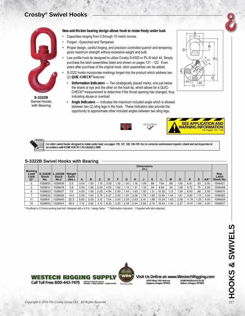
S-3322BSwivel Hookswith Bearing
Crosby® Swivel Hooks
Working Load Limit(t)*
S-3322BStock
No.
L-3322BStock No.†
WeightEach(lbs.)
Dimensions(in.)
Rep. Latch
Stock No.A B C D F G H J K L M O R S AA**2 1028605 1028609 2.5 3.00 1.50 1.75 3.59 1.50 1.00 1.16 1.06 .88 7.64 .88 1.00 6.01 .63 2.00 1096421
3 1028614 1028618 3.8 3.50 1.56 2.00 4.00 1.62 1.13 1.31 1.19 .94 8.60 .94 1.09 6.72 .75 2.00 1096468
5 1028623 1028627 7.0 4.00 1.56 2.25 4.84 2.00 1.44 1.63 1.50 1.31 10.32 1.13 1.36 8.00 .88 2.50 1096515
7 1028632 1028636 14.0 5.00 1.94 2.75 6.27 2.50 1.81 2.06 1.78 1.66 12.84 1.44 1.61 9.90 1.13 3.00 1096562
11 1028641 1028645 22.3 5.62 2.05 3.12 7.54 3.00 2.25 2.63 2.41 1.88 15.24 1.63 2.08 11.74 1.25 4.00 1096609
15 1028650 1028654 36.0 7.12 3.62 4.10 8.33 3.25 2.59 2.94 2.62 2.19 18.64 1.94 2.27 14.41 1.50 4.00 1096657
On Pages 144 - 145
SEE APPLICATION AND WARNING INFORMATION
New anti-friction bearing design allows hook to rotate freely under load.• Capacities ranging from 2 through 15 metric tonnes.• Forged - Quenched and Tempered.• Proper design, careful forging, and precision controlled quench and tempering
gives maximum strength without excessive weight and bulk.• Low profile hook tip designed to utilize Crosby S-4320 or PL-N latch kit. Simply
purchase the latch assemblies listed and shown on pages 121 - 122. Evenyears after purchase of the original hook, latch assemblies can be added.
• S-3322 hooks incorporate markings forged into the product which address two(2) QUIC-CHECK® features:• Deformation Indicators — Two strategically placed marks, one just below
the shank or eye and the other on the hook tip, which allows for a QUIC-CHECK® measurement to determine if the throat opening has changed, thusindicating abuse or overload
• Angle Indicators — Indicates the maximum included angle which is allowedbetween two (2) sling legs in the hook. These indicators also provide theopportunity to approximate other included angles between two sling legs.
For other swivel hooks designed to rotate under load, see pages 119, 127, 128, 136-139. Use in corrosive environment requires shank and nut inspection in accordance with ASME B30.10-1.10.4 (b)(5)(c) 2009.
Copyright © 2016 The Crosby Group LLC All Rights Reserved144
WARNING• Loads may disengage from hook if proper procedures are
not followed.• A falling load may cause serious injury or death.• See OSHA Rule 1926.1431(g)(1)(i)(A) and 1926.1501(g)(4)(iv)(B)
for personnel hoisting by cranes and derricks, and OSHADirective CPL 2-1.36 - Interim Inspection Procedures DuringCommunication Tower Construction Activities. A Crosby 319, 320 or 322 hook with a PL latch attached and securedwith a bolt, nut and cotter pin (or toggle pin) may be usedfor lifting personnel. A Crosby 319N, 320N or 322N hookwith an S-4320 latch attached and secured with cotter pinor bolt, nut and pin; or a PL-N latch attached and securedwith toggle pin may be used for lifting personnel. A hookwith a Crosby SS-4055 latch attached shall NOT be used forpersonnel lifting.
• See OSHA Directive CPL 2-1.36 - Crosby does notrecommend the placement of lanyards directly into thepositive locking Crosby hook when hoisting personnel. Crosby requires that all suspension systems (verticallifelines / lanyard) shall be gathered at the positive lockedload hook by use of a master link, or a bolt-type shacklesecured with cotter pin.
• Threads or Split-Nut may corrode and/or strip and drop the load.• Remove securement nut to inspect or to replace S-322 and
S-3319 bearing washers (2).• Hook must always support the load. The load must never be
supported by the latch.• Never apply more force than the hook’s assigned Working
Load Limit (WLL) rating.• Read and understand these instructions before using hook.
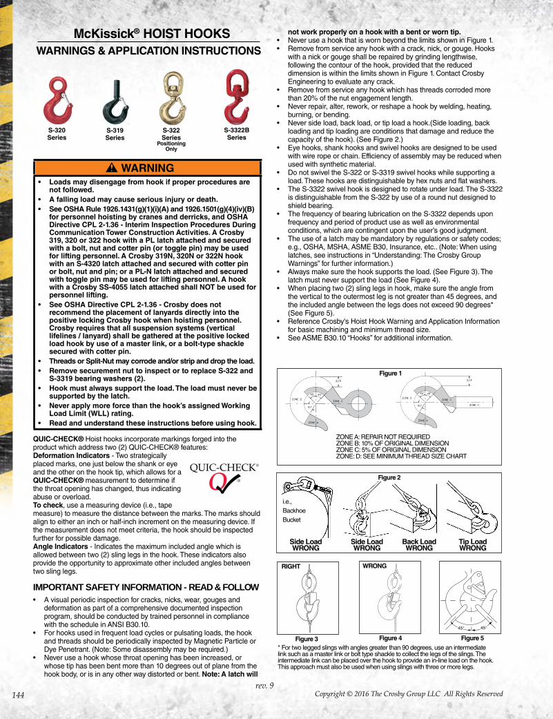
S-319 Series
S-320 Series
S-3322BSeries
ZONE A: REPAIR NOT REQUIREDZONE B: 10% OF ORIGINAL DIMENSIONZONE C: 5% OF ORIGINAL DIMENSIONZONE: D: SEE MINIMUM THREAD SIZE CHART
* For two legged slings with angles greater than 90 degrees, use an intermediate link such as a master link or bolt type shackle to collect the legs of the slings. The intermediate link can be placed over the hook to provide an in-line load on the hook. This approach must also be used when using slings with three or more legs.
Figure 3 Figure 4 Figure 5
RIGHT WRONG
QUIC-CHECK® Hoist hooks incorporate markings forged into the product which address two (2) QUIC-CHECK® features:Deformation Indicators - Two strategically placed marks, one just below the shank or eye and the other on the hook tip, which allows for a QUIC-CHECK® measurement to determine if the throat opening has changed, thus indicating abuse or overload.To check, use a measuring device (i.e., tape measure) to measure the distance between the marks. The marks should align to either an inch or half-inch increment on the measuring device. If the measurement does not meet criteria, the hook should be inspected further for possible damage.Angle Indicators - Indicates the maximum included angle which is allowed between two (2) sling legs in the hook. These indicators also provide the opportunity to approximate other included angles between two sling legs.
IMPORTANT SAFETY INFORMATION - READ & FOLLOW• A visual periodic inspection for cracks, nicks, wear, gouges and
deformation as part of a comprehensive documented inspectionprogram, should be conducted by trained personnel in compliancewith the schedule in ANSI B30.10.
• For hooks used in frequent load cycles or pulsating loads, the hookand threads should be periodically inspected by Magnetic Particle orDye Penetrant. (Note: Some disassembly may be required.)
• Never use a hook whose throat opening has been increased, orwhose tip has been bent more than 10 degrees out of plane from thehook body, or is in any other way distorted or bent. Note: A latch will
not work properly on a hook with a bent or worn tip.• Never use a hook that is worn beyond the limits shown in Figure 1.• Remove from service any hook with a crack, nick, or gouge. Hooks
with a nick or gouge shall be repaired by grinding lengthwise,following the contour of the hook, provided that the reduceddimension is within the limits shown in Figure 1. Contact CrosbyEngineering to evaluate any crack.
• Remove from service any hook which has threads corroded morethan 20% of the nut engagement length.
• Never repair, alter, rework, or reshape a hook by welding, heating,burning, or bending.
• Never side load, back load, or tip load a hook.(Side loading, backloading and tip loading are conditions that damage and reduce thecapacity of the hook). (See Figure 2.)
• Eye hooks, shank hooks and swivel hooks are designed to be usedwith wire rope or chain. Efficiency of assembly may be reduced whenused with synthetic material.
• Do not swivel the S-322 or S-3319 swivel hooks while supporting aload. These hooks are distinguishable by hex nuts and flat washers.
• The S-3322 swivel hook is designed to rotate under load. The S-3322is distinguishable from the S-322 by use of a round nut designed toshield bearing.
• The frequency of bearing lubrication on the S-3322 depends uponfrequency and period of product use as well as environmentalconditions, which are contingent upon the user’s good judgment.
• The use of a latch may be mandatory by regulations or safety codes; e.g., OSHA, MSHA, ASME B30, Insurance, etc.. (Note: When usinglatches, see instructions in “Understanding: The Crosby GroupWarnings” for further information.)
• Always make sure the hook supports the load. (See Figure 3). Thelatch must never support the load (See Figure 4).
• When placing two (2) sling legs in hook, make sure the angle fromthe vertical to the outermost leg is not greater than 45 degrees, andthe included angle between the legs does not exceed 90 degrees*(See Figure 5).
• Reference Crosby's Hoist Hook Warning and Application Informationfor basic machining and minimum thread size.
• See ASME B30.10 “Hooks” for additional information.
Figure 2
Side LoadWRONG
i.e.,BackhoeBucket
Side LoadWRONG
Back LoadWRONG
Tip LoadWRONG
rev. 9
S-322 Series
Positioning Only
McKissick® HOIST HOOKS WARNINGS & APPLICATION INSTRUCTIONS
Figure 1
Copyright © 2016 The Crosby Group LLC All Rights Reserved 145
HO
OK
S &
SW
IVE
LS
Warning and Application Instructions For McKISSICK® Hook Latch Kit
WARNING• Loads may disengage from hook if proper procedures are
not followed.• A falling load may cause serious injury or death.• See OSHA Rule 1926.1431(g)(1)(i)(A) and 1926.1501(g)(4)(iv)
(B) for personnel hoisting for cranes and derricks. Only aCrosby or McKissick hook with a PL Latch attached andsecured with bolt, nut and cotter (or Crosby Toggle Pin) ora Crosby hook with a S-4320 Latch attached and securedwith a cotter pin, or a Crosby SHUR-LOC® hook in thelocked position may be used for any personnel hoisting. A hook with a Crosby SS-4055 latch attached shall NOT beused for personnel lifting.
• Hook must always support the load. The load must neverbe supported by the latch.
• Do not use this latch in applications requiring non-sparking. • Read and understand these instructions before using hook
and latch.
IMPORTANT SAFETY INFORMATION - READ & FOLLOW• Always inspect hook and latch before using.• Never use a latch that is distorted or bent.• Always make sure spring will force the latch against the tip of the
hook.• Always make sure hook supports the load. The latch must never
support the load. (See Figures 1 & 2)• When placing two (2) sling legs in hooks, make sure the angle
between the legs is less the 90° and if the hook or load is tilted,nothing bears against the bottom of this latch. (See Figures 3 & 4)
• Latches are intended to retain loose sling or devices underslack conditions.
• Latches are not intended to be an anti-fouling device.
RIGHT WRONG WRONG
Figure 2Figure 1 Figure 4Figure 3
RIGHT
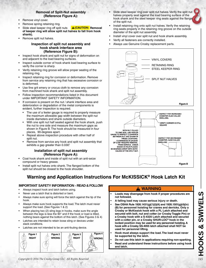
Removal of Split-Nut assembly (Reference Figure A):
• Remove vinyl cover. • Remove spring retaining ring.• Slide steel keeper ring off split nuts Removal
of keeper ring will allow split nut halves to fall from hook shank).
• Remove split nut halves.
Inspection of split nut assembly and hook shank interface area
(Reference Figure B):• Inspect hook shank and split nut for signs of deformation on
and adjacent to the load bearing surfaces.• Inspect outside corner of hook shank load bearing surface to
verify the corner is sharp. • Verify retaining ring groove will allow proper seating of the
retaining ring.• Inspect retaining ring for corrosion or deformation. Remove
from service any retaining ring that has excessive corrosion oris deformed.
• Use fine grit emery or crocus cloth to remove any corrosionfrom machined hook shank and split nut assembly.
• Follow inspection recommendations listed in this documentunder IMPORTANT SAFETY INFORMATION.
• If corrosion is present on the nut / shank interface area anddeterioration or degradation of the metal components isevident, further inspection is required.• The use of a feeler gauge is required to properly measure
the maximum allowable gap width between the split nutinside diameters and shank outside diameters.
• With one split nut half seated against the hook shank, pushthe nut to one side and measure the maximum gaps asshown in Figure B. The hook should be measured in fourplaces, 90-degrees apart.
• Repeat above inspection procedure with other half ofsplit nut.
• Remove from service any hook and split nut assembly thatexhibits a gap greater than 0.030”.
Installation of split nut assembly (Reference Figure A):
• Coat hook shank and inside of split nut with an anti-seizecompound or heavy grease.
• Install split nut halves onto shank. The flanged bottom of thesplit nut should be closest to the hook shoulder.
• Slide steel keeper ring over split nut halves. Verify the split nuthalves properly seat against the load bearing surface of thehook shank and the steel keeper ring seats against the flangeof the split nut.
• Install retaining ring onto split nut halves. Verify the retainingring seats properly in the retaining ring groove on the outsidediameter of the split nut assembly.
• Install vinyl cover over split nut and hook shank assembly.• Verify all fasteners are correctly installed. • Always use Genuine Crosby replacement parts.
VINYL COVERS
RETAINING RINGSTEEL KEEPER RING
SPLIT NUT HALVES
Figure A
Figure B
(CAUTION: