honeywell udc2500
TRANSCRIPT
UDC2500 Universal Digital Controller
Product Manual
51-52-25-135 August 2005
8/05 UDC2500 Universal Digital Controller Product Manual ii
About This Document
Abstract This document provides descriptions and procedures for the Installation, Configuration, Operation, and Troubleshooting of your UDC2500 Controller.
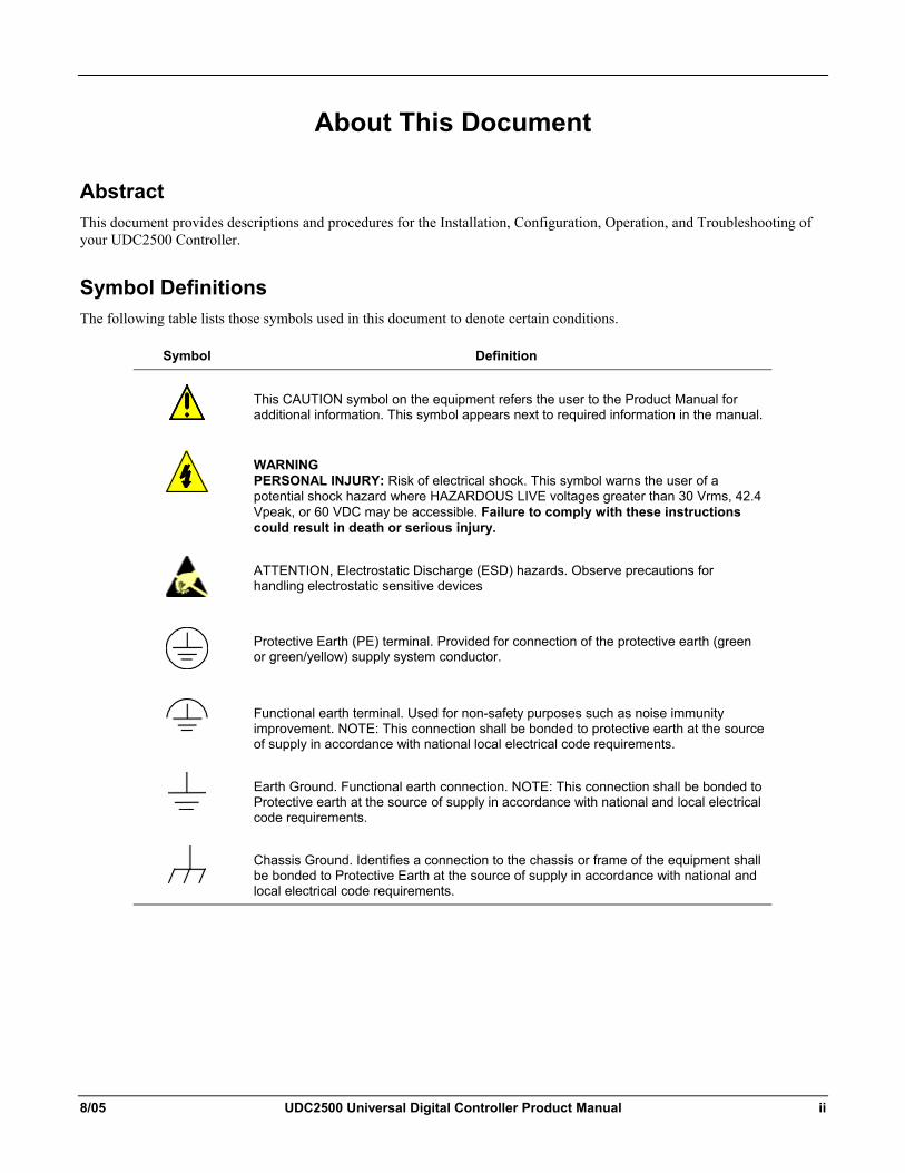
Symbol Definitions The following table lists those symbols used in this document to denote certain conditions.
Symbol Definition
This CAUTION symbol on the equipment refers the user to the Product Manual for additional information. This symbol appears next to required information in the manual.
WARNING PERSONAL INJURY: Risk of electrical shock. This symbol warns the user of a potential shock hazard where HAZARDOUS LIVE voltages greater than 30 Vrms, 42.4 Vpeak, or 60 VDC may be accessible. Failure to comply with these instructions could result in death or serious injury.
ATTENTION, Electrostatic Discharge (ESD) hazards. Observe precautions for handling electrostatic sensitive devices
Protective Earth (PE) terminal. Provided for connection of the protective earth (green or green/yellow) supply system conductor.
Functional earth terminal. Used for non-safety purposes such as noise immunity improvement. NOTE: This connection shall be bonded to protective earth at the source of supply in accordance with national local electrical code requirements.
Earth Ground. Functional earth connection. NOTE: This connection shall be bonded to Protective earth at the source of supply in accordance with national and local electrical code requirements.
Chassis Ground. Identifies a connection to the chassis or frame of the equipment shall be bonded to Protective Earth at the source of supply in accordance with national and local electrical code requirements.
iii UDC2500 Universal Digital Controller Product Manual 8/05
Contents
1 INTRODUCTION ...................................................................................................1 1.1 Overview.........................................................................................................................................1 1.2 Function of Displays and Keys .......................................................................................................3 1.3 Process Instrument Explorer Software............................................................................................4 1.4 CE Conformity (Europe).................................................................................................................5
2 INSTALLATION.....................................................................................................7 2.1 Overview.........................................................................................................................................7 2.2 Condensed Specifications ...............................................................................................................8 2.3 Model Number Interpretation .......................................................................................................11 2.4 Control and Alarm Relay Contact Information.............................................................................13 2.5 Mounting.......................................................................................................................................14 2.6 Wiring ...........................................................................................................................................16
2.6.1 Electrical Considerations ...................................................................................................16 2.7 Wiring Diagrams...........................................................................................................................18
3 CONFIGURATION...............................................................................................31 3.1 Overview.......................................................................................................................................31 3.2 Configuration Prompt Hierarchy ..................................................................................................32 3.3 Configuration Procedure...............................................................................................................33 3.4 Tuning Set Up Group....................................................................................................................34 3.5 SP Ramp Set Up Group ................................................................................................................38 3.6 Accutune Set Up Group ................................................................................................................42 3.7 Algorithm Set Up Group...............................................................................................................45 3.8 Output Set Up Group ....................................................................................................................50 3.9 Input 1 Set Up Group....................................................................................................................54 3.10 Input 2 Set Up Group ................................................................................................................58 3.11 Control Set Up Group ...............................................................................................................60 3.12 Options Group ...........................................................................................................................66 3.13 Communications Group ............................................................................................................72 3.14 Alarms Set Up Group ................................................................................................................75 3.15 Display Set Up Group ...............................................................................................................81 3.16 Configuration Record Sheet ......................................................................................................83
8/05 UDC2500 Universal Digital Controller Product Manual iv
4 MONITORING AND OPERATING THE CONTROLLER.....................................85 4.1 Overview.......................................................................................................................................85 4.2 Operator Interface .........................................................................................................................86 4.3 Entering a Security Code ..............................................................................................................86 4.4 Lockout Feature ............................................................................................................................87 4.5 Monitoring Your Controller..........................................................................................................89
4.5.1 Annunciators ......................................................................................................................89 4.5.2 Viewing the operating parameters......................................................................................90 4.5.3 Diagnostic Messages..........................................................................................................91
4.6 Single Display Functionality.........................................................................................................93 4.7 Start Up Procedure for Operation .................................................................................................95 4.8 Control Modes ..............................................................................................................................96
4.8.1 Mode Definitions ...............................................................................................................96 4.8.2 What happens when you change modes.............................................................................97
4.9 Setpoints........................................................................................................................................97 4.10 Timer .........................................................................................................................................98 4.11 Accutune III.............................................................................................................................100
4.11.1 Tune for Simplex Outputs ............................................................................................101 4.11.2 Tune for Duplex (Heat/Cool) .......................................................................................101 4.11.3 Using AUTOMATIC TUNE at start-up for Duplex (Heat/Cool).................................102 4.11.4 Using BLENDED TUNE at start-up for Duplex (Heat/Cool)......................................102 4.11.5 Using MANUAL TUNE at start-up for Duplex (Heat/Cool) .......................................103 4.11.6 Error Codes...................................................................................................................105
4.12 Fuzzy Overshoot Suppression .................................................................................................106 4.13 Using Two Sets of Tuning Constants......................................................................................106 4.14 Alarm Setpoints.......................................................................................................................108 4.15 Three Position Step Control Algorithm...................................................................................109 4.16 Setting a Failsafe Output Value for Restart After a Power Loss.............................................110 4.17 Setting Failsafe Mode..............................................................................................................111 4.18 Setpoint Rate/Ramp/Program Overview .................................................................................111 4.19 Setpoint Ramp .........................................................................................................................112 4.20 Setpoint Rate ...........................................................................................................................113 4.21 Setpoint Ramp/Soak Programming .........................................................................................114
5 INPUT CALIBRATION.......................................................................................121 5.1 Overview.....................................................................................................................................121 5.2 Minimum and Maximum Range Values .....................................................................................122 5.3 Preliminary Information..............................................................................................................124 5.4 Input 1 Set Up Wiring.................................................................................................................125 5.5 Input 1 Calibration Procedure .....................................................................................................129 5.6 Input 2 Set Up Wiring.................................................................................................................131
v UDC2500 Universal Digital Controller Product Manual 8/05
5.7 Input 2 Calibration Procedure .....................................................................................................132 5.8 Restore Input Factory Calibration...............................................................................................134
6 OUTPUT CALIBRATION...................................................................................137 6.1 Overview.....................................................................................................................................137 6.2 Current Output Calibration .........................................................................................................138 6.3 Auxiliary Output Calibration ......................................................................................................140 6.4 Restore Output Factory Calibration Procedure ...........................................................................142
7 TROUBLESHOOTING/SERVICE......................................................................144 7.1 Overview.....................................................................................................................................144 7.2 Troubleshooting Aids..................................................................................................................145 7.3 Power-up Tests............................................................................................................................147 7.4 Status Tests .................................................................................................................................147 7.5 Background Tests........................................................................................................................148 7.6 Controller Failure Symptoms......................................................................................................150 7.7 Troubleshooting Procedures .......................................................................................................151 7.8 Restoring Factory Configuration ................................................................................................160
8 PARTS LIST ......................................................................................................161 8.1 Exploded View............................................................................................................................161 8.2 Removing the chassis..................................................................................................................163
9 MODBUS RTU FUNCTION CODES..................................................................164 9.1 Overview.....................................................................................................................................164 9.2 General Information....................................................................................................................164 9.3 Function Code 20 (14h) - Read Configuration Reference Data..................................................166
9.3.1 Read Configuration Examples .........................................................................................168 9.4 Function Code 21 (15h) - Write Configuration Reference Data.................................................170
9.4.1 Write Configuration Examples ........................................................................................172
10 MODBUS READ, WRITE AND OVERRIDE PARAMETERS PLUS EXCEPTION CODES........................................................................................................................173
10.1 Overview .................................................................................................................................173 10.2 Reading Control Data..............................................................................................................174 10.3 Read Software Options Status .................................................................................................175 10.4 Miscellaneous Read Onlys ......................................................................................................176
10.4.1 Register Addresses for Read Onlys ..............................................................................176 10.4.2 SetPoint Program Read Only Information....................................................................176
10.5 Setpoints ..................................................................................................................................177
8/05 UDC2500 Universal Digital Controller Product Manual vi
10.6 Using a Computer Setpoint (Overriding Controller Setpoint) ................................................178 10.7 Configuration Parameters........................................................................................................180
10.7.1 Tuning ..........................................................................................................................180 10.7.2 SP Ramp/Rate/Program................................................................................................182 10.7.3 Accutune.......................................................................................................................185 10.7.4 Algorithm .....................................................................................................................186 10.7.5 Output Algorithms........................................................................................................187 10.7.6 Input 1...........................................................................................................................188 10.7.7 Input 2...........................................................................................................................191 10.7.8 Control..........................................................................................................................193 10.7.9 Options .........................................................................................................................195 10.7.10 Communications...........................................................................................................197 10.7.11 Alarms ..........................................................................................................................198 10.7.12 Display..........................................................................................................................201
10.8 Modbus RTU Exception Codes...............................................................................................202
11 ETHERNET TCP/IP ...........................................................................................204 11.1 Overview .................................................................................................................................204
12 FURTHER INFORMATION................................................................................205 12.1 Modbus RTU Serial Communications ....................................................................................205 12.2 Modbus Messaging on TCP/IP................................................................................................205 12.3 How to Apply Digital Instrumentation in Severe Electrical Noise Environments ..................205
13 INDEX................................................................................................................207
vii UDC2500 Universal Digital Controller Product Manual 8/05
Tables Table 2-1 Condensed Specifications _____________________________________________________ 8 Table 2-2 Control Relay Contact Information _____________________________________________ 13 Table 2-3 Alarm Relay Contact Information ______________________________________________ 13 Table 2-4 Mounting Procedure_________________________________________________________ 15 Table 2-5 Permissible Wiring Bundling__________________________________________________ 17 Table 2-6 Universal Output Functionality and Restrictions___________________________________ 19 Table 2-7 Terminals for connecting a UDC to a MDI Compliant Hub or Switch __________________ 29 Table 2-8 Terminals for connecting a UDC directly to a PC utilizing a straight-through cable ________ 29 Table 3-1 Configuration Topics ________________________________________________________ 31 Table 3-2 Configuration Prompt Hierarchy _______________________________________________ 32 Table 3-3 Configuration Procedure _____________________________________________________ 33 Table 3-4 TUNING Group (Numeric Code 100) Function Prompts ____________________________ 34 Table 3-5 SPRAMP Group (Numeric Code 200) Function Prompts ____________________________ 38 Table 3-6 ATUNE Group (Numeric Code 300) Function Prompts _____________________________ 43 Table 3-7 ALGOR Group (Numeric Code 400) Function Prompts _____________________________ 45 Table 3-8 OUTPUT Group (Numeric Code 500) Function Prompts ____________________________ 50 Table 3-9 INPUT 1 Group (Numeric Code 600) Function Prompts ____________________________ 54 Table 3-10 INPUT2 Group (Numeric Code 700) Function Prompts ____________________________ 58 Table 3-11 Table 3-12 CONTRL Group (Numeric Code 800) Function Prompts _________________ 60 Table 3-13 OPTION Group (Numeric Code 900) Function Prompts ___________________________ 66 Table 3-14 Communications Group (Numeric Code 1000) Function Prompts ____________________ 72 Table 3-15 ALARMS Group (Numeric Code 1100) Function Prompts _________________________ 75 Table 3-16 DISPLY Group (Numeric Code 1200) Function Prompts___________________________ 81 Table 4-1 Procedure to Enter a Security Code _____________________________________________ 87 Table 4-2 Annunciators ______________________________________________________________ 89 Table 4-3 Lower Display Key Parameter Prompts__________________________________________ 90 Table 4-4 Diagnostic Messages_________________________________________________________ 91 Table 4-5 Single Display Parameters ____________________________________________________ 94 Table 4-6 Procedure for Starting Up the Controller_________________________________________ 95 Table 4-7 Control Mode Definitions ____________________________________________________ 96 Table 4-8 Changing Control Modes (Dual Display Only) ____________________________________ 97 Table 4-9 Procedure for Changing the Local Setpoints ______________________________________ 97 Table 4-10 Procedure for Switching Between Setpoints _____________________________________ 98 Table 4-11 Procedure for Starting “TUNE”______________________________________________ 101 Table 4-12 Procedure for Using AUTOMATIC TUNE at Start-up for Duplex Control ____________ 102 Table 4-13 Procedure for Using BLENDED TUNE at Start-up for Duplex Control_______________ 103 Table 4-14 Procedure for Using MANUAL TUNE for Heat side of Duplex Control ______________ 103 Table 4-15 Procedure for Using MANUAL TUNE for Cool side of Duplex Control ______________ 104 Table 4-16 Procedure for Accessing Accutune Error Codes _________________________________ 105 Table 4-17 Accutune Error Codes _____________________________________________________ 105 Table 4-18 Set Up Procedure _________________________________________________________ 107 Table 4-19 Procedure for Switching PID SETS from the Keyboard ___________________________ 108 Table 4-20 Procedure for Displaying Alarm Setpoints _____________________________________ 108 Table 4-21 Procedure for Displaying 3Pstep Motor Position_________________________________ 109 Table 4-22 Procedure for Setting a Failsafe Value_________________________________________ 110 Table 4-23 Procedure for Setting a Failsafe Mode_________________________________________ 111 Table 4-24 Running A Setpoint Ramp __________________________________________________ 112 Table 4-25 Program Contents_________________________________________________________ 114
8/05 UDC2500 Universal Digital Controller Product Manual viii
Table 4-26 Run/Monitor Functions ____________________________________________________ 119 Table 5-1 Voltage, Milliamp and Resistance Equivalents for Input 1 Range Values ______________ 122 Table 5-2 Voltage and Milliamp Equivalents for Input 2 Range Values ________________________ 124 Table 5-3 Equipment Needed_________________________________________________________ 124 Table 5-4 Set Up Wiring Procedure for Thermocouple Inputs Using an Ice Bath ________________ 125 Table 5-5 Set Up Wiring Procedure for Thermocouple Inputs using Thermocouple Source ________ 126 Table 5-6 Set Up Wiring Procedure for RTD Inputs _______________________________________ 126 Table 5-7 Set Up Wiring Procedure for Radiamatic, Millivolts, Volts or Thermocouple Differential Inputs
(Except 0-10 Volts) _____________________________________________________________ 127 Table 5-8 Set Up Wiring Procedure for 0 to 10 Volts ______________________________________ 128 Table 5-9 Set Up Wiring Procedure for Milliampere Inputs _________________________________ 128 Table 5-10 Input 1 Calibration Procedure (Numeric Code 10000) ____________________________ 129 Table 5-11 Set Up Wiring Procedure for 0 to 20 mA or 4 to 20 mA Inputs – Input 2______________ 131 Table 5-12 Set Up Wiring Procedure for 0 to 2 Volts, 0 to 5 Volts, or 1 to 5 Volts – Input 2________ 132 Table 5-13 Input 2 Calibration Procedure (Numeric Code 20000) ____________________________ 133 Table 5-14 Restore Factory Calibration _________________________________________________ 134 Table 6-1 Set Up Wiring Procedure for Current Output ____________________________________ 138 Table 6-2 Current Output Calibration Procedure (Numeric Code 30000) ______________________ 139 Table 6-3 Set Up Wiring Procedure for Auxiliary Output ___________________________________ 140 Table 6-4 Auxiliary Output Calibration Procedure (Numeric Code 50000) _____________________ 141 Table 6-5 Restore Factory Calibration Procedure _________________________________________ 142 Table 7-1 Procedure for Identifying the Software Version __________________________________ 146 Table 7-2 Procedure for Displaying the Status Test (Numeric Code 1200) Results _______________ 147 Table 7-3 Background Tests__________________________________________________________ 148 Table 7-4 Controller Failure Symptoms_________________________________________________ 150 Table 7-5 Troubleshooting Power Failure Symptoms ______________________________________ 152 Table 7-6 Troubleshooting Current Output Failure ________________________________________ 152 Table 7-7 Troubleshooting Three Position Step Control Output Failure ________________________ 153 Table 7-8 Troubleshooting Time Proportional Output Failure _______________________________ 154 Table 7-9 Troubleshooting Current/Time or Time/Current Proportional Output Failure ___________ 155 Table 7-10 Troubleshooting Alarm Relay Output Failure ___________________________________ 156 Table 7-11 Troubleshooting a Keyboard Failure __________________________________________ 157 Table 7-12 Troubleshooting a RS-485 Communications Failure______________________________ 158 Table 7-13 Troubleshooting an Ethernet Communications Failure ___________________________ 159 Table 7-14 Troubleshooting Auxiliary Output Failure _____________________________________ 159 Table 7-15 Restoring Factory Configuration _____________________________________________ 160 Table 8-1 Parts Identification _________________________________________________________ 162 Table 8-2 Parts Not Shown___________________________________________________________ 162 Table 8-3 Software Upgrades (see Section Error! Reference source not found.)__________________ 162 Table 9-1 Integer Parameter Type _____________________________________________________ 165 Table 9-2 Floating Point Parameter Type________________________________________________ 165 Table 9-3 Register Address Format for Function Code 20___________________________________ 167 Table 9-4 Register Address Format for Function Code 21___________________________________ 171 Table 10-1 Control Data Parameters ___________________________________________________ 175 Table 10-2 Option Status ____________________________________________________________ 175 Table 10-3 Miscellaneous Read Onlys__________________________________________________ 176 Table 10-4 SetPoint Program Read Only Information ______________________________________ 176 Table 10-5 Setpoint Code Selections ___________________________________________________ 177 Table 10-6 Setpoint Associated Parameters ______________________________________________ 177 Table 10-7 Computer Setpoint Selection ________________________________________________ 178
ix UDC2500 Universal Digital Controller Product Manual 8/05
Table 10-8 Computer Setpoint Associated Parameters _____________________________________ 179 Table 10-9 Set-up Group – Tuning ____________________________________________________ 180 Table 10-10 Set-up Group – Setpoint Ramp/Rate _________________________________________ 182 Table 10-11 Set-up Group – Accutune__________________________________________________ 185 Table 10-12 Set-up Group – Algorithm _________________________________________________ 186 Table 10-13 Set-up Group – Output____________________________________________________ 187 Table 10-14 Set-up Group – Input 1____________________________________________________ 188 Table 10-15 Set-up Group – Input 2____________________________________________________ 191 Table 10-16 Set-up Group – Control ___________________________________________________ 193 Table 10-17 Set-up Group – Options ___________________________________________________ 195 Table 10-18 Set-up Group – Communications____________________________________________ 197 Table 10-19 Set-up Group – Alarms ___________________________________________________ 198 Table 10-20 Set-up Group – Display ___________________________________________________ 201 Table 10-21 Modbus RTU Data Layer Status Exception Codes ______________________________ 203
8/05 UDC2500 Universal Digital Controller Product Manual x
Figures Figure 1-1 UDC2500 Operator Interface (all display items shown) _____________________________ 2 Figure 1-2 Screen capture of Process Instrument Explorer running on a Pocket PC _________________ 4 Figure 1-3 Depiction of infrared communications ___________________________________________ 5 Figure 2-1 Model Number Interpretation _________________________________________________ 12 Figure 2-2 Mounting Dimensions (not to scale)____________________________________________ 14 Figure 2-3 Mounting Methods _________________________________________________________ 15 Figure 2-4 Composite Wiring Diagram __________________________________________________ 20 Figure 2-5 Mains Power Supply________________________________________________________ 21 Figure 2-6 Input 1 Connections ________________________________________________________ 22 Figure 2-7 Input 2 Connections ________________________________________________________ 23 Figure 2-8 Electromechanical Relay Output ______________________________________________ 23 Figure 2-9 Solid State Relay Output ____________________________________________________ 24 Figure 2-10 Open Collector Output _____________________________________________________ 25 Figure 2-11 Dual Electromechanical Relay Option Output ___________________________________ 26 Figure 2-12 Current Output ___________________________________________________________ 26 Figure 2-13 Three Position Step Control Connections w/o Dual Relay Option____________________ 27 Figure 2-14 Three Position Step Control Connections with Dual Relay Option ___________________ 27 Figure 2-15 RS-422/485 Communications Option Connections _______________________________ 28 Figure 2-16 Ethernet Communications Option Connections __________________________________ 28 Figure 2-17 Auxiliary Output and Digital Inputs Option Connections __________________________ 29 Figure 2-18 Transmitter Power for 4-20 mA — 2 wire Transmitter Using Open Collector Alarm 2 Output30 Figure 2-19 Transmitter Power for 4-20 mA — 2 Wire Transmitter Using Auxiliary Output ________ 30 Figure 4-1 Operator Interface__________________________________________________________ 86 Figure 4-2 Functional Overview Block Diagram of the UDC2500 Controller ____________________ 92 Figure 4-3 Ramp/Soak Profile Example_________________________________________________ 117 Figure 4-4 Program Record Sheet _____________________________________________________ 118 Figure 5-1 Input 1 and Input 2 Wiring Terminals _________________________________________ 124 Figure 5-2 Wiring Connections for Thermocouple Inputs Using an Ice Bath ____________________ 125 Figure 5-3 Wiring Connections for Thermocouple Inputs Using Thermocouple Source ___________ 126 Figure 5-4 Wiring Connections for RTD (Resistance Thermometer Device) ____________________ 126 Figure 5-5 Wiring Connections for Radiamatic, Thermocouple Differential, Millivolts or Volts (Except 0 to 10
Volts) ________________________________________________________________________ 127 Figure 5-6 Wiring Connections for 0 to 10 Volts__________________________________________ 128 Figure 5-7 Wiring Connections for 0 to 20 mA or 4 to 20 mA Inputs__________________________ 128 Figure 5-8 Wiring Connections for 0 to 20 mA or 4 to 20 mA Input – Input 2 ___________________ 131 Figure 5-9 Wiring Connections for 0 to 2 Volts, 0 to 5 Volts or 1 to 5 Volts Input – Input 2________ 132 Figure 6-1 Wiring Connections for Calibrating Current Output ______________________________ 138 Figure 6-2 Wiring Connections for Calibrating Auxiliary Output_____________________________ 140 Figure 8-1 UDC2500 Exploded View __________________________________________________ 161 Figure 10-1 Software Option Status Information__________________________________________ 175
Introduction
8/05 UDC2500 Universal Digital Controller Product Manual 1
1 Introduction
1.1 Overview
Function The UDC2500 is a microprocessor-based stand-alone controller. It combines a high degree of functionality and operating simplicity in a 1/4 DIN size controller. This instrument is an ideal controller for regulating temperature and other process variables in numerous heating and cooling applications, as well as in metal working, food, pharmaceuticals, semiconductor, testing and environmental work.
The UDC2500 monitors and controls temperatures and other variables in applications such as environmental chambers, plastic processing machines, furnaces and ovens, and packaging machinery.
Features • 90 – 264 Vac or 24 Vac/dc Power Supply
• Input/Output Isolation
• Isolated Auxiliary Current Output / Digital Inputs
• Modbus RS-485, Infrared, or Ethernet TCP/IP Communications
• Infrared interface
• Timer
• Accutune III Tuning with Fuzzy Logic Overshoot Suppression.
• 2nd Input (Remote Setpoint)
• Setpoint Ramp/Rate/Program
• Three Position Step Control
• Duplex (Heat/Cool)
Easy to Read Displays The dedicated vacuum fluorescent displays with multi-language prompts make the operator interface easy to read, understand and operate. Programmed sequences of displays assure quick and accurate entry of all configurable parameters.
Easy to Operate Simple keystrokes let you select input and range configuration, set the operating parameters that meet you process control needs now, and change them later to meet new ones.
Introduction
2 UDC2500 Universal Digital Controller Product Manual 8/05
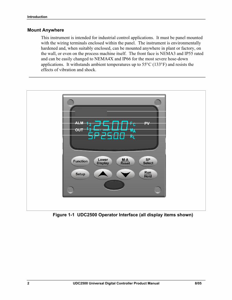
Mount Anywhere This instrument is intended for industrial control applications. It must be panel mounted with the wiring terminals enclosed within the panel. The instrument is environmentally hardened and, when suitably enclosed, can be mounted anywhere in plant or factory, on the wall, or even on the process machine itself. The front face is NEMA3 and IP55 rated and can be easily changed to NEMA4X and IP66 for the most severe hose-down applications. It withstands ambient temperatures up to 55°C (133°F) and resists the effects of vibration and shock.
Figure 1-1 UDC2500 Operator Interface (all display items shown)
Introduction
8/05 UDC2500 Universal Digital Controller Product Manual 3
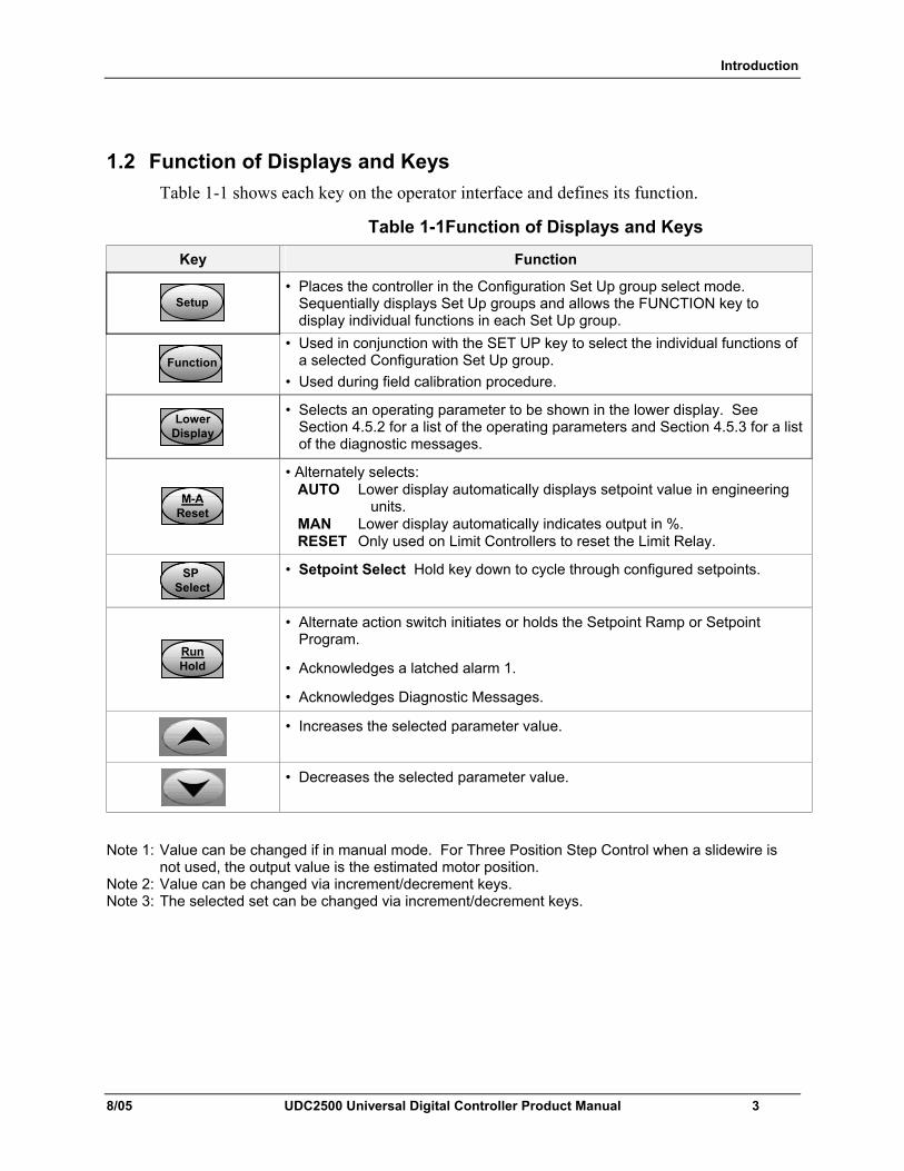
1.2 Function of Displays and Keys Table 1-1 shows each key on the operator interface and defines its function.
Table 1-1Function of Displays and Keys
Key Function
SetupSetup
• Places the controller in the Configuration Set Up group select mode. Sequentially displays Set Up groups and allows the FUNCTION key to display individual functions in each Set Up group.
FunctionFunctionFunction
• Used in conjunction with the SET UP key to select the individual functions of a selected Configuration Set Up group.
• Used during field calibration procedure.
LowerDisplayLower
DisplayLower
Display
• Selects an operating parameter to be shown in the lower display. See Section 4.5.2 for a list of the operating parameters and Section 4.5.3 for a list of the diagnostic messages.
M-AResetM-A
ResetM-A
Reset
• Alternately selects: AUTO Lower display automatically displays setpoint value in engineering
units. MAN Lower display automatically indicates output in %. RESET Only used on Limit Controllers to reset the Limit Relay.
SP Select
SP Select
SP Select
• Setpoint Select Hold key down to cycle through configured setpoints.
RunHoldRunHoldRunHold
• Alternate action switch initiates or holds the Setpoint Ramp or Setpoint Program.
• Acknowledges a latched alarm 1.
• Acknowledges Diagnostic Messages.
• Increases the selected parameter value.
• Decreases the selected parameter value.
Note 1: Value can be changed if in manual mode. For Three Position Step Control when a slidewire is
not used, the output value is the estimated motor position. Note 2: Value can be changed via increment/decrement keys. Note 3: The selected set can be changed via increment/decrement keys.
Introduction
4 UDC2500 Universal Digital Controller Product Manual 8/05
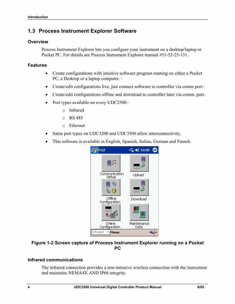
1.3 Process Instrument Explorer Software
Overview Process Instrument Explorer lets you configure your instrument on a desktop/laptop or Pocket PC. For details see Process Instrument Explorer manual #51-52-25-131.
Features • Create configurations with intuitive software program running on either a Pocket
PC, a Desktop or a laptop computer. ·
• Create/edit configurations live, just connect software to controller via comm port.·
• Create/edit configurations offline and download to controller later via comm. port.·
• Port types available on every UDC2500:·
o Infrared
o RS 485
o Ethernet
• Same port types on UDC3200 and UDC3500 allow interconnectivity.
• This software is available in English, Spanish, Italian, German and French.
Figure 1-2 Screen capture of Process Instrument Explorer running on a Pocket PC
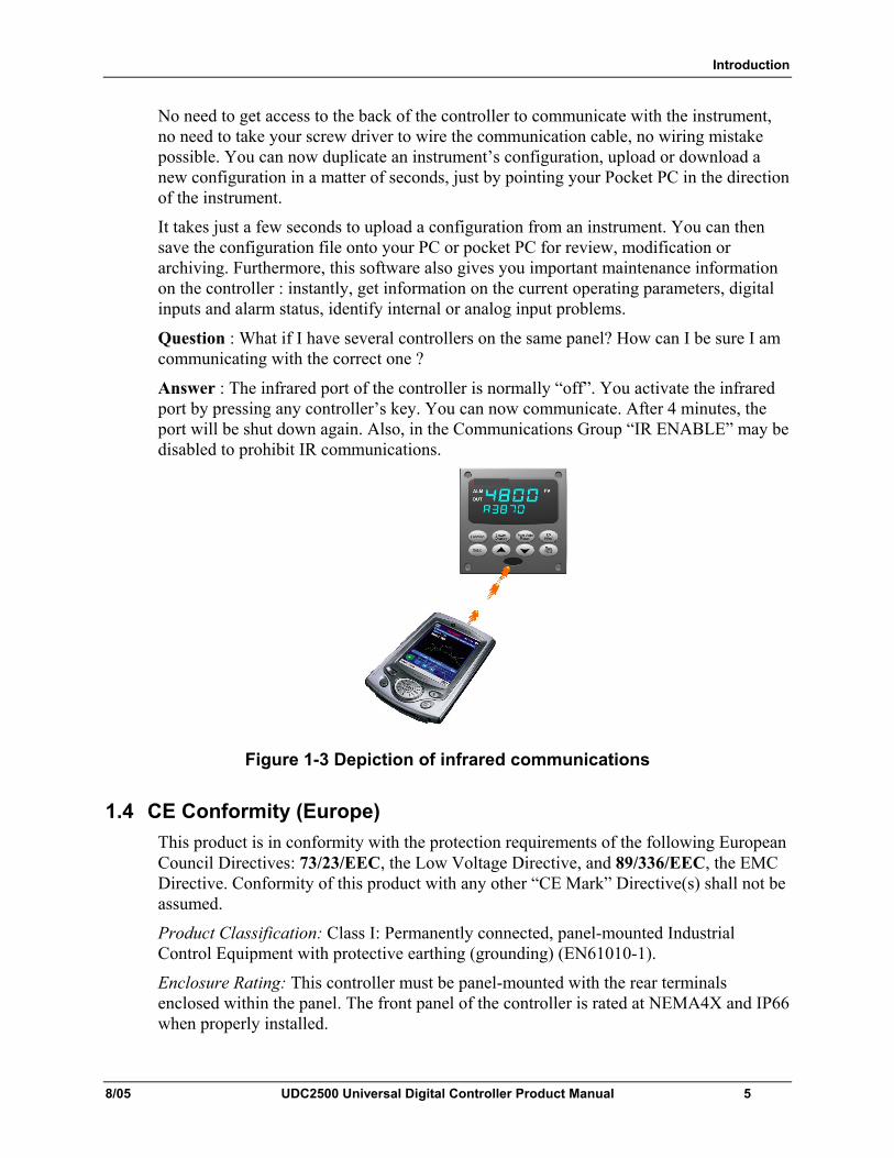
Infrared communications The infrared connection provides a non-intrusive wireless connection with the instrument and maintains NEMA4X AND IP66 integrity.
Introduction
8/05 UDC2500 Universal Digital Controller Product Manual 5
No need to get access to the back of the controller to communicate with the instrument, no need to take your screw driver to wire the communication cable, no wiring mistake possible. You can now duplicate an instrument’s configuration, upload or download a new configuration in a matter of seconds, just by pointing your Pocket PC in the direction of the instrument.
It takes just a few seconds to upload a configuration from an instrument. You can then save the configuration file onto your PC or pocket PC for review, modification or archiving. Furthermore, this software also gives you important maintenance information on the controller : instantly, get information on the current operating parameters, digital inputs and alarm status, identify internal or analog input problems.
Question : What if I have several controllers on the same panel? How can I be sure I am communicating with the correct one ?
Answer : The infrared port of the controller is normally “off”. You activate the infrared port by pressing any controller’s key. You can now communicate. After 4 minutes, the port will be shut down again. Also, in the Communications Group “IR ENABLE” may be disabled to prohibit IR communications.
Figure 1-3 Depiction of infrared communications
1.4 CE Conformity (Europe) This product is in conformity with the protection requirements of the following European Council Directives: 73/23/EEC, the Low Voltage Directive, and 89/336/EEC, the EMC Directive. Conformity of this product with any other “CE Mark” Directive(s) shall not be assumed.
Product Classification: Class I: Permanently connected, panel-mounted Industrial Control Equipment with protective earthing (grounding) (EN61010-1).
Enclosure Rating: This controller must be panel-mounted with the rear terminals enclosed within the panel. The front panel of the controller is rated at NEMA4X and IP66 when properly installed.
Introduction
6 UDC2500 Universal Digital Controller Product Manual 8/05
Installation Category (Overvoltage Category): Category II (EN61010-1)
Pollution Degree: Pollution Degree 2: Normally non-conductive pollution with occasional conductivity caused by condensation. (Ref. IEC 664-1)
EMC Classification: Group 1, Class A, ISM Equipment (EN61326, emissions), Industrial Equipment (EN61326, immunity)
Method of EMC Assessment: Technical File (TF)
Declaration of Conformity: 51453655
Deviation from the installation conditions specified in this manual, and the special conditions for CE conformity in Subsection 2.1, may invalidate this product’s conformity with the Low Voltage and EMC Directives.
ATTENTION
The emission limits of EN61326 are designed to provide reasonable protection against harmful interference when this equipment is operated in an industrial environment. Operation of this equipment in a residential area may cause harmful interference. This equipment generates, uses, and can radiate radio frequency energy and may cause interference to radio and television reception when the equipment is used closer than 30 meters (98 feet) to the antenna(e). In special cases, when highly susceptible apparatus is used in close proximity, the user may have to employ additional mitigating measures to further reduce the electromagnetic emissions of this equipment.
WARNING
If this equipment is used in a manner not specified by the manufacturer, the protection provided by the equipment may be impaired.
Installation
8/05 UDC2500 Universal Digital Controller Product Manual 7
2 Installation
2.1 Overview
Introduction Installation of the UDC2500 consists of mounting and wiring the controller according to the instructions given in this section. Read the pre-installation information, check the model number interpretation (Subsection 2.3), and become familiar with your model selections, then proceed with installation.
What’s in this section? The following topics are covered in this section.
TOPIC See Page
2.1 Overview 7
2.2 Condensed Specifications 8
2.3 Model Number Interpretation 11
2.4 Control and Alarm Relay Contact Information 13
2.5 Mounting 14
2.6 Wiring 16
2.7 Wiring Diagrams Composite Wiring Diagram AC Line Voltage Input 1 Connections Input 2 Connections Relay Output Electromechanical Solid State Open Collector Dual Electromechanical Relay Current Output Connections Three Position Step Control Connections w/o Dual Relay Three Position Step Control Connections with Dual Relay RS-422/485 Communications Option Ethernet Communications Option Auxiliary Output and Digital Inputs Option Transmitter Power using Open Collector Output Transmitter Power using Auxiliary Output
18 20 21 22 23
23 24 25 26 26 27 27 28 28 29 30 30
Installation
8 UDC2500 Universal Digital Controller Product Manual 8/05
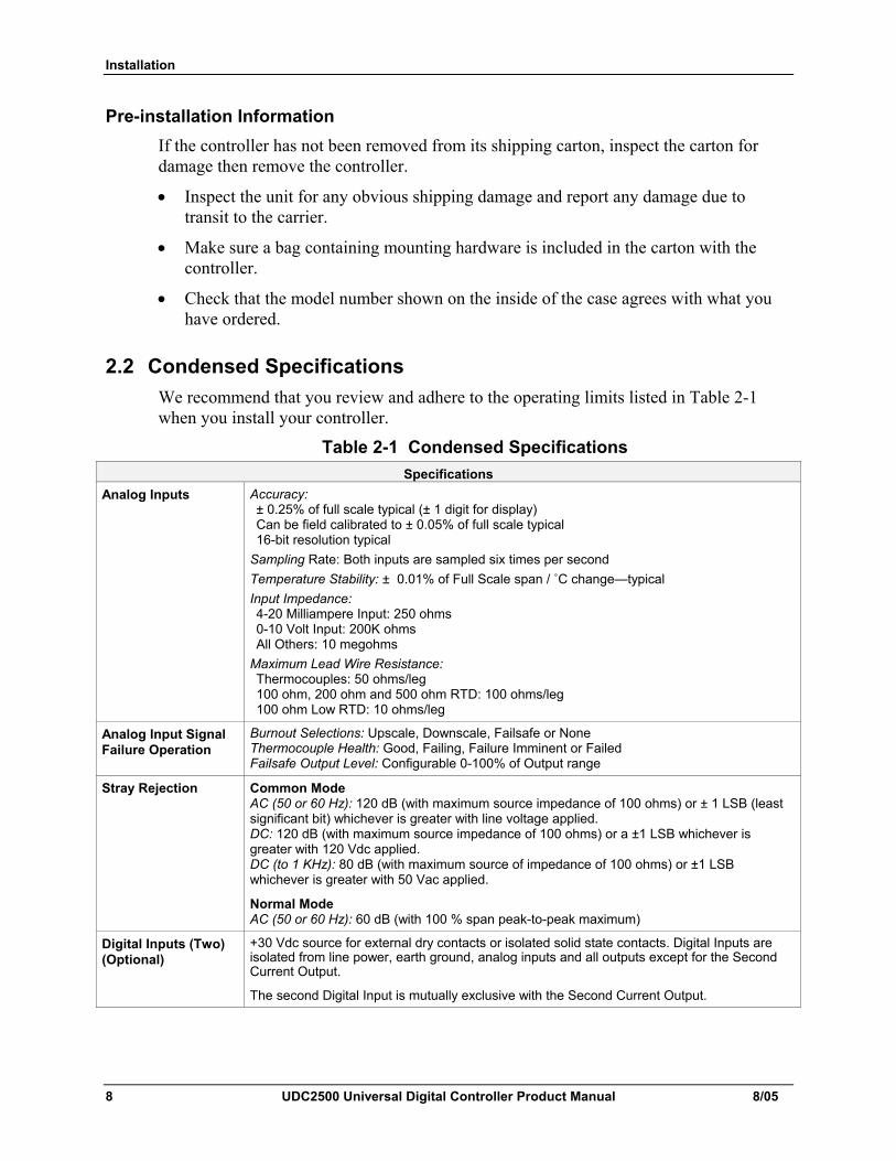
Pre-installation Information If the controller has not been removed from its shipping carton, inspect the carton for damage then remove the controller.
• Inspect the unit for any obvious shipping damage and report any damage due to transit to the carrier.
• Make sure a bag containing mounting hardware is included in the carton with the controller.
• Check that the model number shown on the inside of the case agrees with what you have ordered.
2.2 Condensed Specifications We recommend that you review and adhere to the operating limits listed in Table 2-1 when you install your controller.
Table 2-1 Condensed Specifications Specifications
Analog Inputs Accuracy: ± 0.25% of full scale typical (± 1 digit for display) Can be field calibrated to ± 0.05% of full scale typical 16-bit resolution typical
Sampling Rate: Both inputs are sampled six times per second Temperature Stability: ± 0.01% of Full Scale span / ˚C change—typical Input Impedance: 4-20 Milliampere Input: 250 ohms 0-10 Volt Input: 200K ohms All Others: 10 megohms
Maximum Lead Wire Resistance: Thermocouples: 50 ohms/leg 100 ohm, 200 ohm and 500 ohm RTD: 100 ohms/leg 100 ohm Low RTD: 10 ohms/leg
Analog Input Signal Failure Operation
Burnout Selections: Upscale, Downscale, Failsafe or None Thermocouple Health: Good, Failing, Failure Imminent or Failed Failsafe Output Level: Configurable 0-100% of Output range
Stray Rejection Common Mode AC (50 or 60 Hz): 120 dB (with maximum source impedance of 100 ohms) or ± 1 LSB (least significant bit) whichever is greater with line voltage applied. DC: 120 dB (with maximum source impedance of 100 ohms) or a ±1 LSB whichever is greater with 120 Vdc applied. DC (to 1 KHz): 80 dB (with maximum source of impedance of 100 ohms) or ±1 LSB whichever is greater with 50 Vac applied.
Normal Mode AC (50 or 60 Hz): 60 dB (with 100 % span peak-to-peak maximum)
Digital Inputs (Two) (Optional)
+30 Vdc source for external dry contacts or isolated solid state contacts. Digital Inputs are isolated from line power, earth ground, analog inputs and all outputs except for the Second Current Output.
The second Digital Input is mutually exclusive with the Second Current Output.
Installation
8/05 UDC2500 Universal Digital Controller Product Manual 9
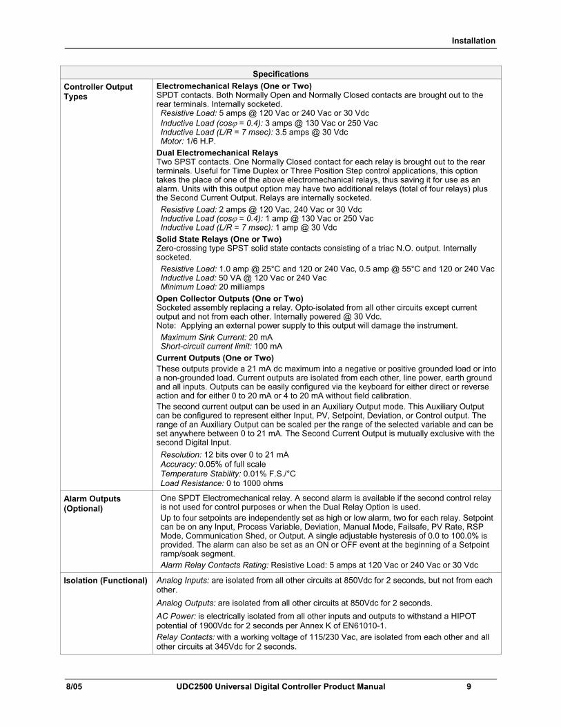
Specifications Controller Output Types
Electromechanical Relays (One or Two) SPDT contacts. Both Normally Open and Normally Closed contacts are brought out to the rear terminals. Internally socketed. Resistive Load: 5 amps @ 120 Vac or 240 Vac or 30 Vdc Inductive Load (cosϕ = 0.4): 3 amps @ 130 Vac or 250 Vac Inductive Load (L/R = 7 msec): 3.5 amps @ 30 Vdc Motor: 1/6 H.P.
Dual Electromechanical Relays Two SPST contacts. One Normally Closed contact for each relay is brought out to the rear terminals. Useful for Time Duplex or Three Position Step control applications, this option takes the place of one of the above electromechanical relays, thus saving it for use as an alarm. Units with this output option may have two additional relays (total of four relays) plus the Second Current Output. Relays are internally socketed. Resistive Load: 2 amps @ 120 Vac, 240 Vac or 30 Vdc Inductive Load (cosϕ = 0.4): 1 amp @ 130 Vac or 250 Vac Inductive Load (L/R = 7 msec): 1 amp @ 30 Vdc
Solid State Relays (One or Two) Zero-crossing type SPST solid state contacts consisting of a triac N.O. output. Internally socketed. Resistive Load: 1.0 amp @ 25°C and 120 or 240 Vac, 0.5 amp @ 55°C and 120 or 240 Vac Inductive Load: 50 VA @ 120 Vac or 240 Vac Minimum Load: 20 milliamps
Open Collector Outputs (One or Two) Socketed assembly replacing a relay. Opto-isolated from all other circuits except current output and not from each other. Internally powered @ 30 Vdc. Note: Applying an external power supply to this output will damage the instrument. Maximum Sink Current: 20 mA Short-circuit current limit: 100 mA
Current Outputs (One or Two) These outputs provide a 21 mA dc maximum into a negative or positive grounded load or into a non-grounded load. Current outputs are isolated from each other, line power, earth ground and all inputs. Outputs can be easily configured via the keyboard for either direct or reverse action and for either 0 to 20 mA or 4 to 20 mA without field calibration. The second current output can be used in an Auxiliary Output mode. This Auxiliary Output can be configured to represent either Input, PV, Setpoint, Deviation, or Control output. The range of an Auxiliary Output can be scaled per the range of the selected variable and can be set anywhere between 0 to 21 mA. The Second Current Output is mutually exclusive with the second Digital Input. Resolution: 12 bits over 0 to 21 mA Accuracy: 0.05% of full scale Temperature Stability: 0.01% F.S./°C Load Resistance: 0 to 1000 ohms
Alarm Outputs (Optional)
One SPDT Electromechanical relay. A second alarm is available if the second control relay is not used for control purposes or when the Dual Relay Option is used. Up to four setpoints are independently set as high or low alarm, two for each relay. Setpoint can be on any Input, Process Variable, Deviation, Manual Mode, Failsafe, PV Rate, RSP Mode, Communication Shed, or Output. A single adjustable hysteresis of 0.0 to 100.0% is provided. The alarm can also be set as an ON or OFF event at the beginning of a Setpoint ramp/soak segment. Alarm Relay Contacts Rating: Resistive Load: 5 amps at 120 Vac or 240 Vac or 30 Vdc
Isolation (Functional) Analog Inputs: are isolated from all other circuits at 850Vdc for 2 seconds, but not from each other. Analog Outputs: are isolated from all other circuits at 850Vdc for 2 seconds. AC Power: is electrically isolated from all other inputs and outputs to withstand a HIPOT potential of 1900Vdc for 2 seconds per Annex K of EN61010-1. Relay Contacts: with a working voltage of 115/230 Vac, are isolated from each other and all other circuits at 345Vdc for 2 seconds.
Installation
10 UDC2500 Universal Digital Controller Product Manual 8/05
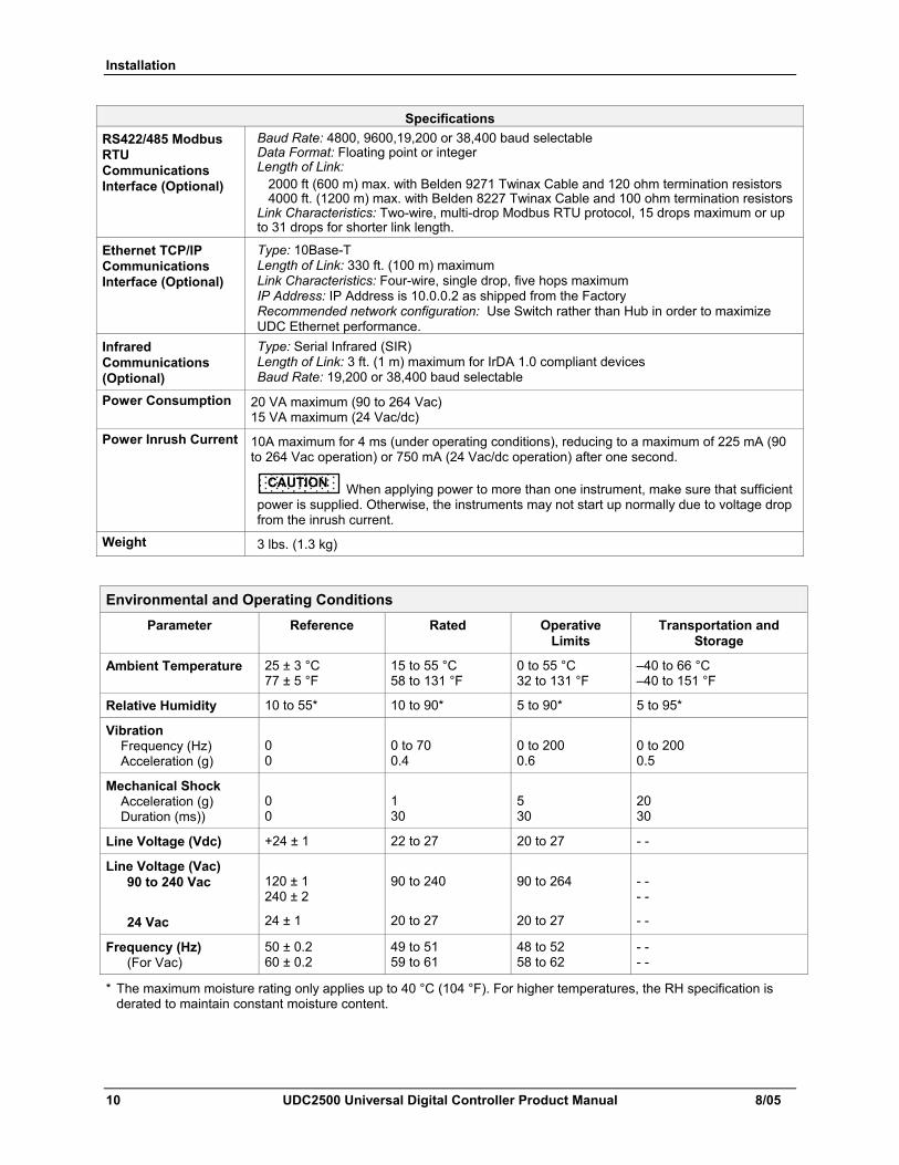
Specifications RS422/485 Modbus RTU Communications Interface (Optional)
Baud Rate: 4800, 9600,19,200 or 38,400 baud selectable Data Format: Floating point or integer Length of Link: 2000 ft (600 m) max. with Belden 9271 Twinax Cable and 120 ohm termination resistors 4000 ft. (1200 m) max. with Belden 8227 Twinax Cable and 100 ohm termination resistorsLink Characteristics: Two-wire, multi-drop Modbus RTU protocol, 15 drops maximum or up to 31 drops for shorter link length.
Ethernet TCP/IP Communications Interface (Optional)
Type: 10Base-T Length of Link: 330 ft. (100 m) maximum Link Characteristics: Four-wire, single drop, five hops maximum IP Address: IP Address is 10.0.0.2 as shipped from the Factory Recommended network configuration: Use Switch rather than Hub in order to maximize UDC Ethernet performance.
Infrared Communications (Optional)
Type: Serial Infrared (SIR) Length of Link: 3 ft. (1 m) maximum for IrDA 1.0 compliant devices Baud Rate: 19,200 or 38,400 baud selectable
Power Consumption 20 VA maximum (90 to 264 Vac) 15 VA maximum (24 Vac/dc)
Power Inrush Current 10A maximum for 4 ms (under operating conditions), reducing to a maximum of 225 mA (90 to 264 Vac operation) or 750 mA (24 Vac/dc operation) after one second.
CAUTION When applying power to more than one instrument, make sure that sufficient power is supplied. Otherwise, the instruments may not start up normally due to voltage drop from the inrush current.
Weight 3 lbs. (1.3 kg)
Environmental and Operating Conditions
Parameter Reference Rated Operative Limits
Transportation and Storage
Ambient Temperature 25 ± 3 °C 77 ± 5 °F
15 to 55 °C 58 to 131 °F
0 to 55 °C 32 to 131 °F
–40 to 66 °C –40 to 151 °F
Relative Humidity 10 to 55* 10 to 90* 5 to 90* 5 to 95*
Vibration Frequency (Hz) Acceleration (g)
0 0
0 to 70 0.4
0 to 200 0.6
0 to 200 0.5
Mechanical Shock Acceleration (g) Duration (ms))
0 0
1 30
5 30
20 30
Line Voltage (Vdc) +24 ± 1 22 to 27 20 to 27 - -
Line Voltage (Vac) 90 to 240 Vac
24 Vac
120 ± 1 240 ± 2
24 ± 1
90 to 240
20 to 27
90 to 264
20 to 27
- - - -
- -
Frequency (Hz) (For Vac)
50 ± 0.2 60 ± 0.2
49 to 51 59 to 61
48 to 52 58 to 62
- - - -
* The maximum moisture rating only applies up to 40 °C (104 °F). For higher temperatures, the RH specification is derated to maintain constant moisture content.
Installation
8/05 UDC2500 Universal Digital Controller Product Manual 11
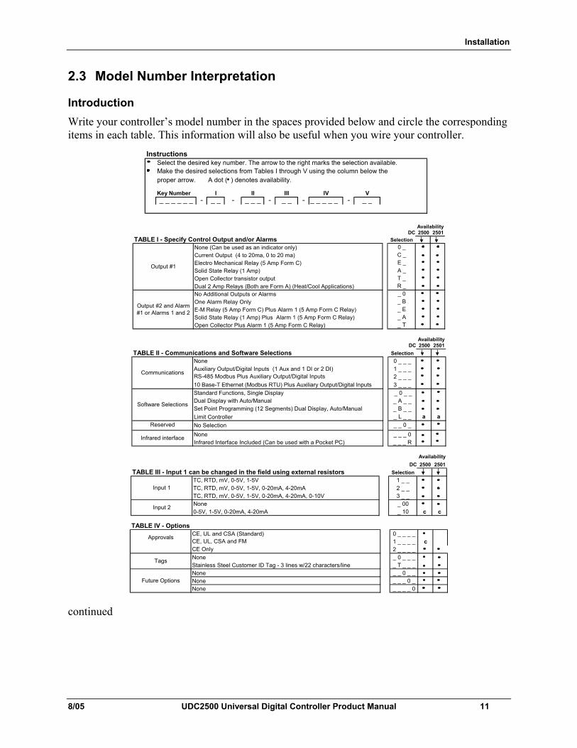
2.3 Model Number Interpretation
Introduction Write your controller’s model number in the spaces provided below and circle the corresponding items in each table. This information will also be useful when you wire your controller.
InstructionsSelect the desired key number. The arrow to the right marks the selection available.Make the desired selections from Tables I through V using the column below the proper arrow. A dot ( ) denotes availability.
Key Number- - - - _ _ _ _ _ -
_ _ _ _ _ _ _ _I
_ _IIIII IV
_ _V
_ _ _
DC 2500 2501TABLE I - Specify Control Output and/or Alarms Selection
Availability
One Alarm Relay Only
0 _C _E _
None (Can be used as an indicator only)Current Output (4 to 20ma, 0 to 20 ma)
Output #1
_ A_ T
Output #2 and Alarm #1 or Alarms 1 and 2
A _T _R _
_ E
Open Collector Plus Alarm 1 (5 Amp Form C Relay)
_ B_ 0
E-M Relay (5 Amp Form C) Plus Alarm 1 (5 Amp Form C Relay)Solid State Relay (1 Amp) Plus Alarm 1 (5 Amp Form C Relay)
Electro Mechanical Relay (5 Amp Form C)Solid State Relay (1 Amp)
No Additional Outputs or Alarms
Open Collector transistor outputDual 2 Amp Relays (Both are Form A) (Heat/Cool Applications)
DC 2500 2501
TABLE II - Communications and Software Selections Selection0 _ _ _1 _ _ _2 _ _ _
10 Base-T Ethernet (Modbus RTU) Plus Auxiliary Output/Digital Inputs 3 _ _ _ _ 0 _ __ A _ __ B _ __ L _ _ a a
No Selection _ _ 0 __ _ _ 0_ _ _ R
Availability
Software Selections
Standard Functions, Single DisplayDual Display with Auto/ManualSet Point Programming (12 Segments) Dual Display, Auto/ManualLimit Controller
Communications
None
Infrared interfaceInfrared Interface Included (Can be used with a Pocket PC)
Auxiliary Output/Digital Inputs (1 Aux and 1 DI or 2 DI)RS-485 Modbus Plus Auxiliary Output/Digital Inputs
None
Reserved
DC 2500 2501TABLE III - Input 1 can be changed in the field using external resistors Selection
1 _ _2 _ _3 _ __ 00_ 10 c c
Input 2 NoneTC, RTD, mV, 0-5V, 1-5V, 0-20mA, 4-20mA, 0-10V
Availability
Input 1TC, RTD, mV, 0-5V, 1-5VTC, RTD, mV, 0-5V, 1-5V, 0-20mA, 4-20mA
0-5V, 1-5V, 0-20mA, 4-20mA TABLE IV - Options
0 _ _ _ _1 _ _ _ _ c2 _ _ _ __ 0 _ _ __ T _ _ __ _ 0 _ __ _ _ 0 __ _ _ _ 0
Approvals CE, UL and CSA (Standard)
Stainless Steel Customer ID Tag - 3 lines w/22 characters/line
CE, UL, CSA and FM
Tags
Future Options None
None
None
None
CE Only
continued
Installation
12 UDC2500 Universal Digital Controller Product Manual 8/05
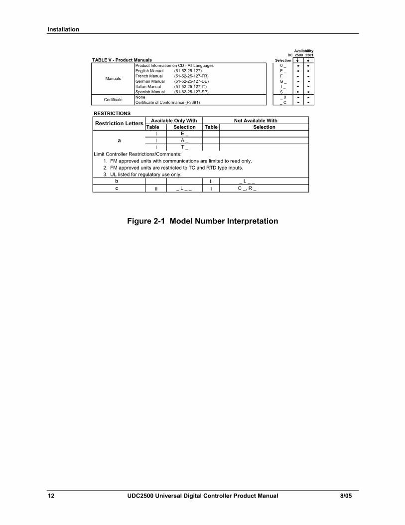
DC 2500 2501TABLE V - Product Manuals Selection
Product Information on CD - All Languages 0 _English Manual (51-52-25-127) E _French Manual (51-52-25-127-FR) F _German Manual (51-52-25-127-DE) G _Italian Manual (51-52-25-127-IT) I _Spanish Manual (51-52-25-127-SP) S _
_ 0_ C
Availability
Certificate of Conformance (F3391)Certificate None
Manuals
RESTRICTIONS
Table
Limit Controller Restrictions/Comments:1. FM approved units with communications are limited to read only.2. FM approved units are restricted to TC and RTD type inputs.3. UL listed for regulatory use only.
II _ L _ _
A _
II _ L _ _I
I
Table Selection
a
Restriction Letters
I
Not Available WithAvailable Only WithSelection
I T _
E _
C _, R _bc
Figure 2-1 Model Number Interpretation
Installation
8/05 UDC2500 Universal Digital Controller Product Manual 13
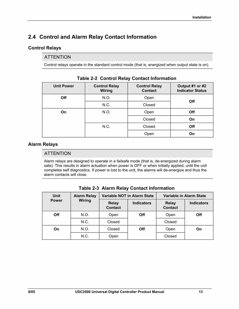
2.4 Control and Alarm Relay Contact Information
Control Relays
ATTENTION Control relays operate in the standard control mode (that is, energized when output state is on).
Table 2-2 Control Relay Contact Information
Unit Power Control Relay Wiring
Control Relay Contact
Output #1 or #2 Indicator Status
N.O. Open Off
N.C. Closed
Off
Open Off N.O.
Closed On
Closed Off
On
N.C.
Open On
Alarm Relays
ATTENTION Alarm relays are designed to operate in a failsafe mode (that is, de-energized during alarm sate). This results in alarm actuation when power is OFF or when initially applied, until the unit completes self diagnostics. If power is lost to the unit, the alarms will de-energize and thus the alarm contacts will close.
Table 2-3 Alarm Relay Contact Information
Variable NOT in Alarm State Variable in Alarm State Unit Power
Alarm Relay Wiring Relay
Contact Indicators Relay
Contact Indicators
N.O. Open Open Off
N.C. Closed
Off
Closed
Off
N.O. Closed Open On
N.C. Open
Off
Closed
On
Installation
14 UDC2500 Universal Digital Controller Product Manual 8/05
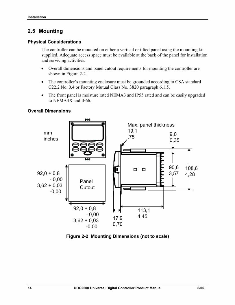
2.5 Mounting
Physical Considerations The controller can be mounted on either a vertical or tilted panel using the mounting kit supplied. Adequate access space must be available at the back of the panel for installation and servicing activities.
• Overall dimensions and panel cutout requirements for mounting the controller are shown in Figure 2-2.
• The controller’s mounting enclosure must be grounded according to CSA standard C22.2 No. 0.4 or Factory Mutual Class No. 3820 paragraph 6.1.5.
• The front panel is moisture rated NEMA3 and IP55 rated and can be easily upgraded to NEMA4X and IP66.
Overall Dimensions
Max. panel thickness19,1.75
PanelCutout
92,0 + 0,8- 0,00
3,62 + 0,03-0,00
92,0 + 0,8- 0,00
3,62 + 0,03-0,00
mminches
17,90,70
113,14,45
90,63,57
108,64,28
9,00,35
Figure 2-2 Mounting Dimensions (not to scale)
Installation
8/05 UDC2500 Universal Digital Controller Product Manual 15
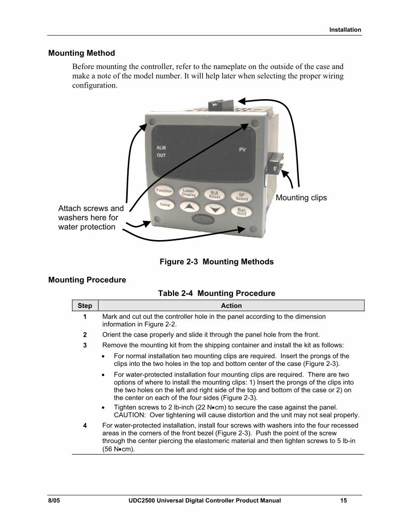
Mounting Method Before mounting the controller, refer to the nameplate on the outside of the case and make a note of the model number. It will help later when selecting the proper wiring configuration.
Figure 2-3 Mounting Methods
Mounting Procedure Table 2-4 Mounting Procedure
Step Action 1 Mark and cut out the controller hole in the panel according to the dimension
information in Figure 2-2. 2 Orient the case properly and slide it through the panel hole from the front. 3 Remove the mounting kit from the shipping container and install the kit as follows:
• For normal installation two mounting clips are required. Insert the prongs of the clips into the two holes in the top and bottom center of the case (Figure 2-3).
• For water-protected installation four mounting clips are required. There are two options of where to install the mounting clips: 1) Insert the prongs of the clips into the two holes on the left and right side of the top and bottom of the case or 2) on the center on each of the four sides (Figure 2-3).
• Tighten screws to 2 lb-inch (22 N•cm) to secure the case against the panel. CAUTION: Over tightening will cause distortion and the unit may not seal properly.
4 For water-protected installation, install four screws with washers into the four recessed areas in the corners of the front bezel (Figure 2-3). Push the point of the screw through the center piercing the elastomeric material and then tighten screws to 5 lb-in (56 N•cm).
Attach screws and washers here for water protection
Mounting clips
Installation
16 UDC2500 Universal Digital Controller Product Manual 8/05
2.6 Wiring 2.6.1 Electrical Considerations
Line voltage wiring This controller is considered “rack and panel mounted equipment” per EN61010-1, Safety Requirements for Electrical Equipment for Measurement, Control, and Laboratory Use, Part 1: General Requirements. Conformity with 72/23/EEC, the Low Voltage Directive requires the user to provide adequate protection against a shock hazard. The user shall install this controller in an enclosure that limits OPERATOR access to the rear terminals.
Mains Power Supply This equipment is suitable for connection to 90 to 264 Vac or to 24 Vac/dc 50/60 Hz, power supply mains. It is the user’s responsibility to provide a switch and non-time delay (North America), quick-acting, high breaking capacity, Type F (Europe), 1/2A, 250V fuse(s), or circuit-breaker for 90-264 Vac applications; or 1 A, 125 V fuse or circuit breaker for 24 Vac/dc applications, as part of the installation. The switch or circuit-breaker shall be located in close proximity to the controller, within easy reach of the OPERATOR. The switch or circuit-breaker shall be marked as the disconnecting device for the controller. CAUTION Applying 90-264 Vac to an instrument rated for 24 Vac/dc will severely
damage the instrument and is a fire and smoke hazard. When applying power to multiple instruments, make certain that sufficient current is supplied. Otherwise, the instruments may not start up normally due to the voltage drop caused by the in-rush current.
Controller Grounding PROTECTIVE BONDING (grounding) of this controller and the enclosure in which it is installed shall be in accordance with National and Local electrical codes. To minimize electrical noise and transients that may adversely affect the system, supplementary bonding of the controller enclosure to a local ground, using a No. 12 (4 mm2) copper conductor, is recommended.
Control/Alarm Circuit Wiring The insulation of wires connected to the Control/Alarm terminals shall be rated for the highest voltage involved. Extra Low Voltage (ELV) wiring (input, current output, and low voltage Control/Alarm circuits) shall be separated from HAZARDOUS LIVE (>30 Vac, 42.4 Vpeak, or 60 Vdc) wiring per Permissible Wiring Bundling, Table 2-5.
Installation
8/05 UDC2500 Universal Digital Controller Product Manual 17
Electrical Noise Precautions Electrical noise is composed of unabated electrical signals which produce undesirable effects in measurements and control circuits. Digital equipment is especially sensitive to the effects of electrical noise. Your controller has built-in circuits to reduce the effect of electrical noise from various sources. If there is a need to further reduce these effects:
• Separate External Wiring—Separate connecting wires into bundles (See Permissible Wiring Bundling - Table 2-5) and route the individual bundles through separate conduit metal trays. Use Suppression Devices—For additional noise protection, you may want to add suppression devices at the external source. Appropriate suppression devices are commercially available.
ATTENTION For additional noise information, refer to document number 51-52-05-01, How to Apply Digital Instrumentation in Severe Electrical Noise Environments.
Permissible Wiring Bundling
Table 2-5 Permissible Wiring Bundling Bundle No. Wire Functions
1 • Line power wiring • Earth ground wiring • Line voltage control relay output wiring • Line voltage alarm wiring
2 Analog signal wire, such as: • Input signal wire (thermocouple, 4 to 20 mA, etc.) • 4-20 mA output signal wiring Digital input signals
3 • Low voltage alarm relay output wiring • Low voltage wiring to solid state type control circuits • Low voltage wiring to open collector type control circuits

Installation
18 UDC2500 Universal Digital Controller Product Manual 8/05
2.7 Wiring Diagrams
Identify Your Wiring Requirements To determine the appropriate diagrams for wiring your controller, refer to the model number interpretation in this section. The model number of the controller is on the outside of the case.
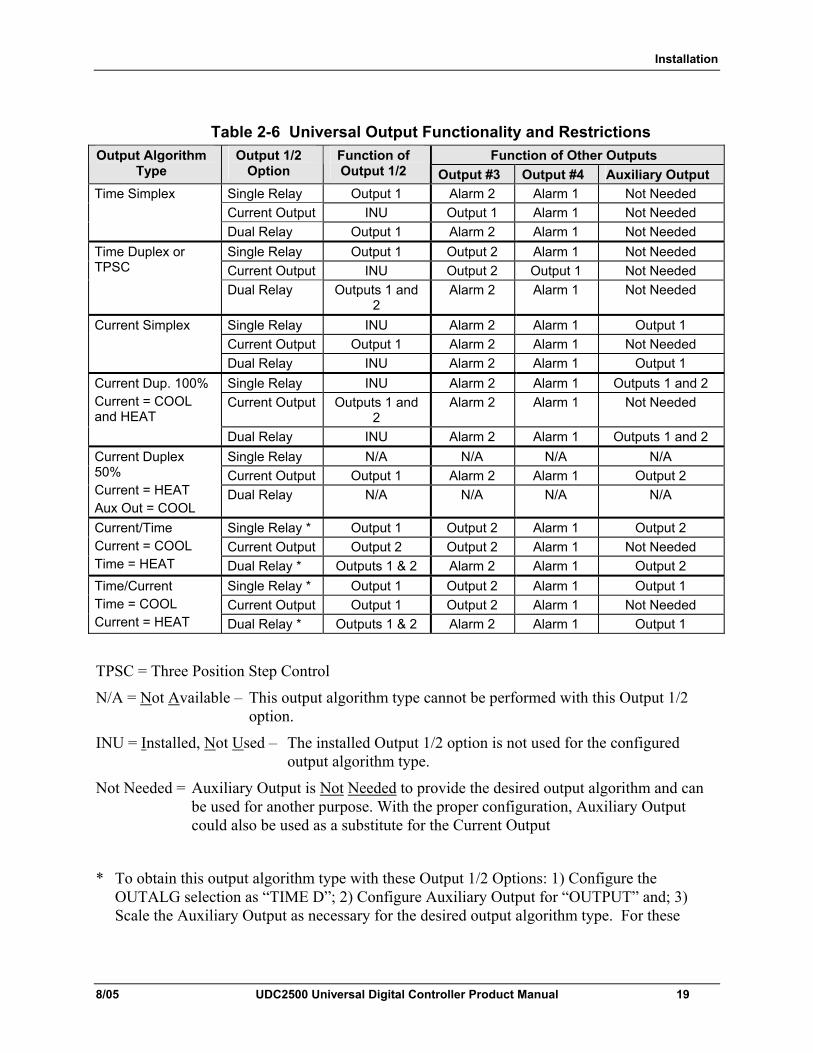
Universal Output Functionality and Restrictions Instruments with multiple outputs can be configured to perform a variety of output types and alarms. For example, an instrument with a current output and two relays can be configured to perform any of the following: 1) Current Simplex with two alarm relays; 2) Current Duplex 100% with two alarm relays (requires auxiliary output); 3) Time Simplex with one alarm relay; 4) Time Duplex with no alarm relays; or 5) Three Position Step Control with no alarm relays. These selections may all be made via the keyboard and by wiring to the appropriate output terminals, there are no internal jumpers or switches to change. This flexibility allows a customer to stock a single instrument which is able to handle a variety of applications. Table 2-6 shows what control types and alarms are available based upon the installed outputs. In this table, when Duplex Control and Reverse Action are configured, “Output 1” is HEAT while “Output 2” is COOL. When Three Position Step Control is configured, “Output 1” is OPEN while “Output 2” is CLOSE. The Output 1/2 option “Single Relay” can be any of the following selections: Electro-Mechanical Relay, Solid-State Relay or Open Collector Output.
Installation
8/05 UDC2500 Universal Digital Controller Product Manual 19
Table 2-6 Universal Output Functionality and Restrictions Function of Other Outputs Output Algorithm
Type Output 1/2
Option Function of Output 1/2 Output #3 Output #4 Auxiliary Output
Single Relay Output 1 Alarm 2 Alarm 1 Not Needed Current Output INU Output 1 Alarm 1 Not Needed
Time Simplex
Dual Relay Output 1 Alarm 2 Alarm 1 Not Needed Single Relay Output 1 Output 2 Alarm 1 Not Needed Current Output INU Output 2 Output 1 Not Needed
Time Duplex or TPSC
Dual Relay Outputs 1 and 2
Alarm 2 Alarm 1 Not Needed
Single Relay INU Alarm 2 Alarm 1 Output 1 Current Output Output 1 Alarm 2 Alarm 1 Not Needed
Current Simplex
Dual Relay INU Alarm 2 Alarm 1 Output 1 Single Relay INU Alarm 2 Alarm 1 Outputs 1 and 2 Current Output Outputs 1 and
2 Alarm 2 Alarm 1 Not Needed
Current Dup. 100% Current = COOL and HEAT
Dual Relay INU Alarm 2 Alarm 1 Outputs 1 and 2 Single Relay N/A N/A N/A N/A Current Output Output 1 Alarm 2 Alarm 1 Output 2
Current Duplex 50% Current = HEAT Aux Out = COOL
Dual Relay N/A N/A N/A N/A
Single Relay * Output 1 Output 2 Alarm 1 Output 2 Current Output Output 2 Output 2 Alarm 1 Not Needed
Current/Time Current = COOL Time = HEAT Dual Relay * Outputs 1 & 2 Alarm 2 Alarm 1 Output 2
Single Relay * Output 1 Output 2 Alarm 1 Output 1 Current Output Output 1 Output 2 Alarm 1 Not Needed
Time/Current Time = COOL Current = HEAT Dual Relay * Outputs 1 & 2 Alarm 2 Alarm 1 Output 1
TPSC = Three Position Step Control
N/A = Not Available – This output algorithm type cannot be performed with this Output 1/2 option.
INU = Installed, Not Used – The installed Output 1/2 option is not used for the configured output algorithm type.
Not Needed = Auxiliary Output is Not Needed to provide the desired output algorithm and can be used for another purpose. With the proper configuration, Auxiliary Output could also be used as a substitute for the Current Output
* To obtain this output algorithm type with these Output 1/2 Options: 1) Configure the OUTALG selection as “TIME D”; 2) Configure Auxiliary Output for “OUTPUT” and; 3) Scale the Auxiliary Output as necessary for the desired output algorithm type. For these
Installation
20 UDC2500 Universal Digital Controller Product Manual 8/05
selections, the Output 1 (HEAT) and Output 2 (COOL) signals will be present both on the Auxiliary Output and on the two relays normally used for Time Duplex.
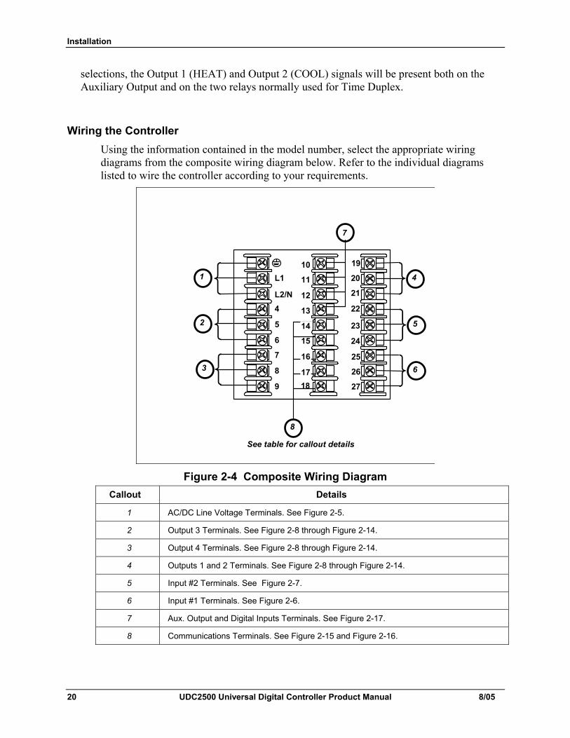
Wiring the Controller Using the information contained in the model number, select the appropriate wiring diagrams from the composite wiring diagram below. Refer to the individual diagrams listed to wire the controller according to your requirements.
L1
L2/N
4
5
6
7
1 10
11
12
13
14
15
16
17
7
8
9
20
21
22
23
24
25
26
27 18
19
See table for callout details
2
3
4
5
6
8
Figure 2-4 Composite Wiring Diagram Callout Details
1 AC/DC Line Voltage Terminals. See Figure 2-5.
2 Output 3 Terminals. See Figure 2-8 through Figure 2-14.
3 Output 4 Terminals. See Figure 2-8 through Figure 2-14.
4 Outputs 1 and 2 Terminals. See Figure 2-8 through Figure 2-14.
5 Input #2 Terminals. See Figure 2-7.
6 Input #1 Terminals. See Figure 2-6.
7 Aux. Output and Digital Inputs Terminals. See Figure 2-17.
8 Communications Terminals. See Figure 2-15 and Figure 2-16.
Installation
8/05 UDC2500 Universal Digital Controller Product Manual 21
4
5
6
7
8
9
10
11
12
13
14
15
16
17
L1
L2/N 22
23
24
25
26
27
Earth Ground
Hot
Neutral AC/DC Line
Voltage
1 2
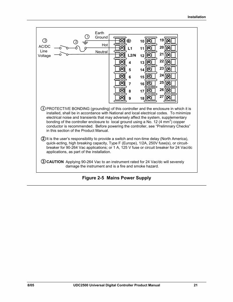
PROTECTIVE BONDING (grounding) of this controller and the enclosure in which it is installed, shall be in accordance with National and local electrical codes. To minimize electrical noise and transients that may adversely affect the system, supplementary bonding of the controller enclosure to local ground using a No. 12 (4 mm2) copper conductor is recommended. Before powering the controller, see “Prelimnary Checks” in this section of the Product Manual.
1
It is the user’s responsibility to provide a switch and non-time delay (North America), quick-acting, high breaking capacity, Type F (Europe), 1/2A, 250V fuse(s), or circuit-breaker for 90-264 Vac applications; or 1 A, 125 V fuse or circuit breaker for 24 Vac/dc applications, as part of the installation.
18
19
20
21
CAUTION Applying 90-264 Vac to an instrument rated for 24 Vac/dc will severely damage the instrument and is a fire and smoke hazard.
3
2
3
Figure 2-5 Mains Power Supply
Installation
22 UDC2500 Universal Digital Controller Product Manual 8/05
25
26
27
Use Thermocouple extension wire only
Thermocouple RTDMillivolt or Volts except 0-10 Volts
source
0-10 Volts Milliamps
–
++
R
–
1 2
3 –
0–10 Volt
source
+ 100K
100K Power
Supply–+
Xmitter+–
250 Ω
25
26
27
+
R
–
25
26
27
+
R
–
25
26
27
+
R
–
1
25
26
27
+
R
–
1
Input #1
mV or Volt
source
25
26
27
Use Thermocouple extension wire only
+
R
–
Thermocouple Differential
+
+
––
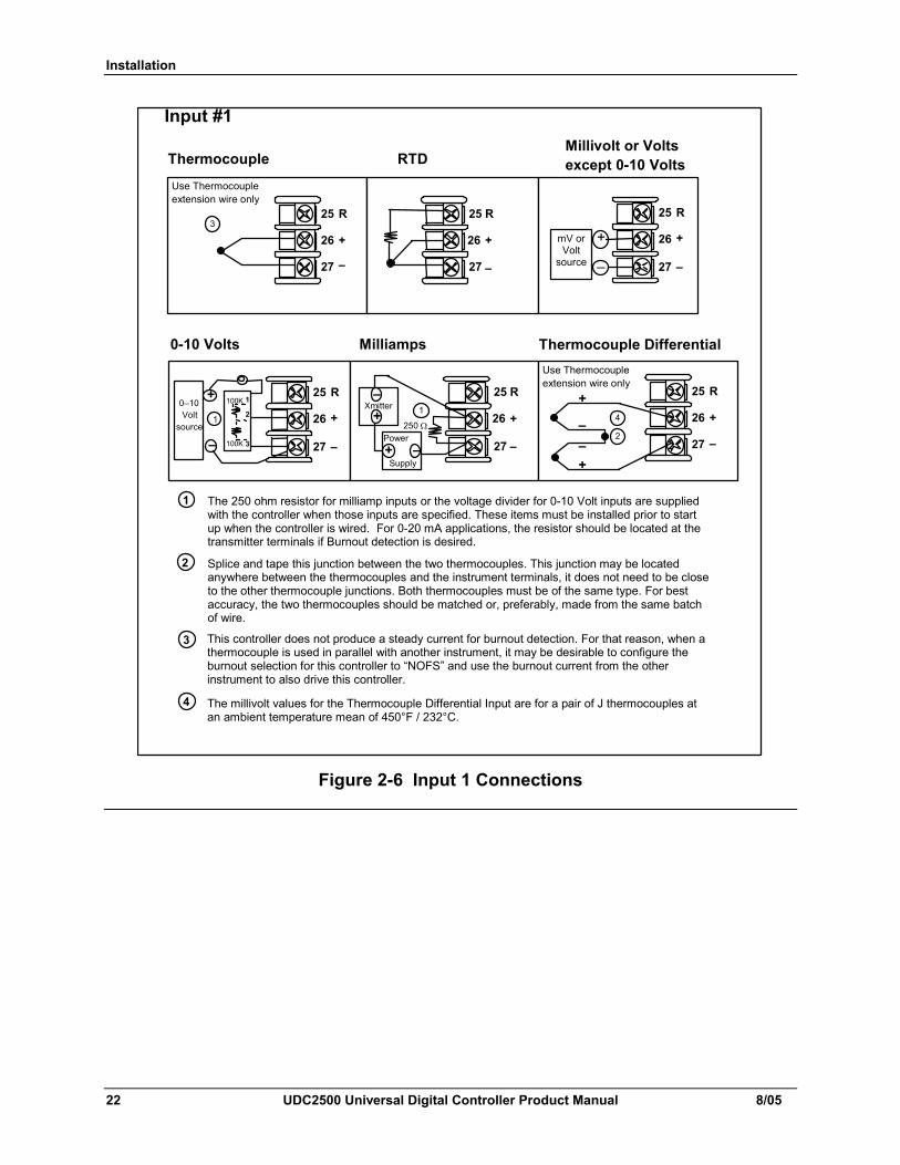
The 250 ohm resistor for milliamp inputs or the voltage divider for 0-10 Volt inputs are supplied with the controller when those inputs are specified. These items must be installed prior to start up when the controller is wired. For 0-20 mA applications, the resistor should be located at the transmitter terminals if Burnout detection is desired.
1
2
Splice and tape this junction between the two thermocouples. This junction may be located anywhere between the thermocouples and the instrument terminals, it does not need to be close to the other thermocouple junctions. Both thermocouples must be of the same type. For best accuracy, the two thermocouples should be matched or, preferably, made from the same batch of wire.
2
This controller does not produce a steady current for burnout detection. For that reason, when a thermocouple is used in parallel with another instrument, it may be desirable to configure the burnout selection for this controller to “NOFS” and use the burnout current from the other instrument to also drive this controller.
3
3
4
The millivolt values for the Thermocouple Differential Input are for a pair of J thermocouples at an ambient temperature mean of 450°F / 232°C.
4
Figure 2-6 Input 1 Connections
Installation
8/05 UDC2500 Universal Digital Controller Product Manual 23
Volts Input
mV or Volt source
Milliamps Input
–
+
22 mA+
23 V+
24 –
1
Input #2
Voltage source
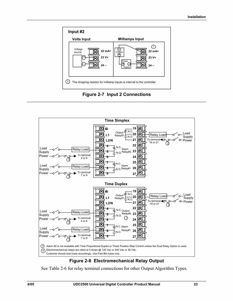
The dropping resistor for milliamp inputs is internal to the controller.1
22 mA+
23 V+
24 –Power
Supply–+
Xmitter+–
Figure 2-7 Input 2 Connections
Alarm Relay#1
OutputRelay#1L1
L2/N
4
5
8
9
N.O.
N.C.
N.O.
Relay Load Load Supply Power
Time Simplex
1 2
2
Alarm #2 is not available with Time Proportional Duplex or Three Position Step Control unless the Dual Relay Option is used. Electromechanical relays are rated at 5 Amps @ 120 Vac or 240 Vac or 30 Vdc.Customer should size fuses accordingly. Use Fast Blo fuses only.
N.C.19
20
21
22
23
24
25
26
27
Time Duplex
Alarm Relay#2
N.C.
N.O.
6
To terminal19 or 21
Alarm Relay#1
Output Relay#1L1
L2/N
4
5
7
8
9
N.O.
N.C.
N.O.
N.C.19
20
21
22
23
24
25
26
27
Output Relay#2
N.C.
N.O.
6
Relay Load Load Supply Power
2 To terminal
19 or 21
7
To terminal 4 or 6
Relay Load
To terminal 7 or 9
Relay Load
2
2
Load Supply Power
Load Supply Power
To terminal 4 or 6
Relay Load
To terminal 7 or 9
Relay Load
2
2
Load Supply Power
Load Supply Power
1
Figure 2-8 Electromechanical Relay Output
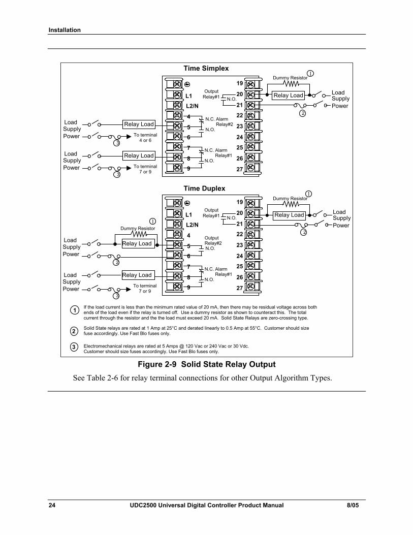
See Table 2-6 for relay terminal connections for other Output Algorithm Types.
Installation
24 UDC2500 Universal Digital Controller Product Manual 8/05
If the load current is less than the minimum rated value of 20 mA, then there may be residual voltage across both ends of the load even if the relay is turned off. Use a dummy resistor as shown to counteract this. The total current through the resistor and the the load must exceed 20 mA. Solid State Relays are zero-crossing type.
2
1
Solid State relays are rated at 1 Amp at 25°C and derated linearly to 0.5 Amp at 55°C. Customer should size fuse accordingly. Use Fast Blo fuses only.
Dummy Resistor
2
Alarm Relay#1
Output Relay#1L1
L2/N
4
5
7
8
9
N.O.
N.C.
N.O.
Relay Load Load Supply Power
Time Simplex
19
20
21
22
23
24
25
26
27
Time Duplex
Alarm Relay#2
N.C.
N.O.
6
Alarm Relay#1
Output Relay#1L1
L2/N
4
5
7
8
9
N.O.
N.C.
N.O.
19
20
21
22
23
24
25
26
27
2
Output Relay#2N.O.
6
Relay Load
To terminal 7 or 9
Relay Load
Load Supply Power
2
3
Load Supply Power
Load Supply Power
Dummy Resistor
Dummy Resistor
1
Relay Load
Electromechanical relays are rated at 5 Amps @ 120 Vac or 240 Vac or 30 Vdc. Customer should size fuses accordingly. Use Fast Blo fuses only.
3
1
1
To terminal 4 or 6
Relay Load
To terminal 7 or 9
Relay Load
3
3
Load Supply Power
Load Supply Power
Figure 2-9 Solid State Relay Output
See Table 2-6 for relay terminal connections for other Output Algorithm Types.
Installation
8/05 UDC2500 Universal Digital Controller Product Manual 25
Alarm Relay#1
L1
L2/N
4
5
7
8
9
N.C.
N.O.
Time Simplex
2 3
Alarm #2 is not available with Time Proportional Duplex or Three Position Step Control unless the Dual Relay option is used. Electromechanical relays are rated at 5 Amps @ 120 Vac or 240 Vac or 30 Vdc. Customer should size fuses accordingly. Use Fast Blo fuses only.
19
20
21
22
23
24
25
26
27
Time Duplex
Alarm Relay#2
N.C.
N.O.
6
Alarm Relay#1
L1
L2/N
4
5
7
8
9
N.C.
N.O.
19
20
21
22
23
24
25
26
27
6
To terminal 7 or 9
Relay Load
3
Load Supply Power
–
+ +–
Output #11
+
–
Customer Supplied Electromechanical relay
Customer Supplied Solid-State relay
–
++–
Output #11
+
–
Customer Supplied Electromechanical relay
Customer Supplied Solid-State relay
– ++
– Output #2
1
+
–
Customer Supplied Electromechanical relay
Customer Supplied Solid-State relay
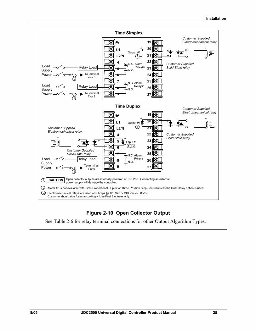
CAUTION Open collector outputs are internally powered at +30 Vdc. Connecting an external power supply will damage the controller. 1
2
To terminal 4 or 6
Relay Load
To terminal 7 or 9
Relay Load
3
3
Load Supply Power
Load Supply Power
Figure 2-10 Open Collector Output See Table 2-6 for relay terminal connections for other Output Algorithm Types.
Installation
26 UDC2500 Universal Digital Controller Product Manual 8/05
Alarm Relay#1
Out Relay#1L1
L2/N
4
5
7
8
9
N.O.
N.C.
N.O.
Cool Relay Load Load
Supply Power
Time Duplex with a Dual Relay Board
1
1
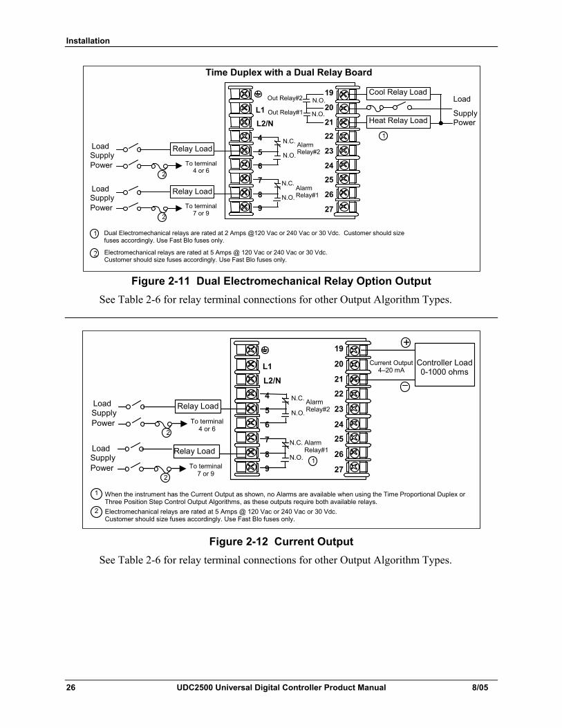
Dual Electromechanical relays are rated at 2 Amps @120 Vac or 240 Vac or 30 Vdc. Customer should size fuses accordingly. Use Fast Blo fuses only.
N.O.19
20
21
22
23
24
25
26
27
To terminal 4 or 6
Alarm Relay#2
N.C.
N.O.
6
Relay Load
To terminal 7 or 9
Relay Load
2
2
Load Supply Power
Load Supply Power
Heat Relay Load
Out Relay#2
2 Electromechanical relays are rated at 5 Amps @ 120 Vac or 240 Vac or 30 Vdc. Customer should size fuses accordingly. Use Fast Blo fuses only.
Figure 2-11 Dual Electromechanical Relay Option Output
See Table 2-6 for relay terminal connections for other Output Algorithm Types.
Alarm Relay#1
L1
L2/N
4
5
7
8
9
N.C.
N.O.
2
When the instrument has the Current Output as shown, no Alarms are available when using the Time Proportional Duplex or Three Position Step Control Output Algorithms, as these outputs require both available relays. Electromechanical relays are rated at 5 Amps @ 120 Vac or 240 Vac or 30 Vdc. Customer should size fuses accordingly. Use Fast Blo fuses only.
19
20
21
22
23
24
25
26
27
6
To terminal 7 or 9
Relay Load
2
Load Supply Power
+
Controller Load0-1000 ohms
–
Current Output 4–20 mA
1
1
To terminal 4 or 6
Alarm Relay#2
N.C.
N.O. Relay Load
2
Load Supply Power
Figure 2-12 Current Output See Table 2-6 for relay terminal connections for other Output Algorithm Types.
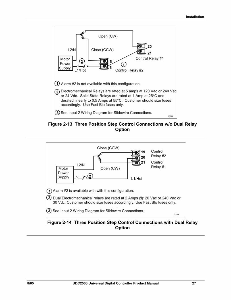
Installation
8/05 UDC2500 Universal Digital Controller Product Manual 27
20
21
5 6
Control Relay #1 Motor Power Supply
Close (CCW)
Open (CW)
Control Relay #2
xxxx
Alarm #2 is not available with this configuration.
1 L1/Hot
L2/N
2
2
See Input 2 Wi ring Diagram for Slidewire Connections.
1
3
Electromechanical Relays are rated at 5 amps at 120 Vac or 240 Vac or 24 Vdc. Solid State Relays are rated at 1 Amp at 25°C and derated linearly to 0.5 Amps at 55°C. Customer should size fuses accordingly. Use Fast Blo fuses only.
Figure 2-13 Three Position Step Control Connections w/o Dual Relay Option
19 20 21
Motor Power Supply
Close (CCW)
Open (CW) Control Relay #1
Control Relay #2
L2/N
L1/Hot
Alarm #2 is available with with this configuration.
2 Dual Electromechanical relays are rated at 2 Amps @120 Vac or 240 Vac or 30 Vdc. Customer should size fuses accordingly. Use Fast Blo fuses only.
2
xxxx See Input 2 Wiring Diagram for Slidewire Connections.
1
3
Figure 2-14 Three Position Step Control Connections with Dual Relay Option
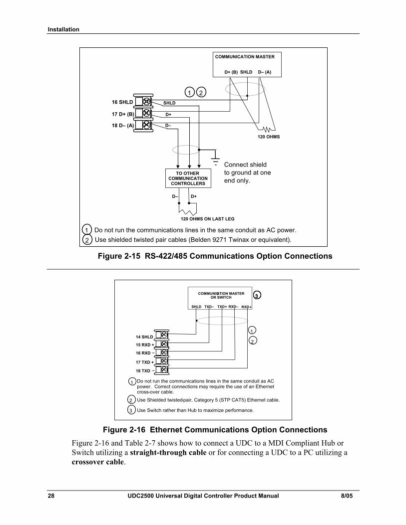
Installation
28 UDC2500 Universal Digital Controller Product Manual 8/05
1 Do not run the communications lines in the same conduit as AC power.
D–
D+
COMMUNICATION MASTER
D+ (B) SHLD D– (A)
120 OHMS
TO OTHER COMMUNICATION
CONTROLLERS
D+D–
120 OHMS ON LAST LEG
16 SHLD
17 D+ (B)
18 D– (A)
Connect shield to ground at one end only.
SHLD
2 Use shielded twisted pair cables (Belden 9271 Twinax or equivalent).
2 1
Figure 2-15 RS-422/485 Communications Option Connections
1 Do not run the communications lines in the same conduit as AC power. Correct connections may require the use of an Ethernet cross-over cable.
COMMUNICATION MASTER OR SWITCH
RXD+SHLD
16 RXD-
17 TXD+
18 TXD-
14 SHLD
15 RXD+
RXD- TXD+ TXD-
1
2 Use Shielded twisted-pair, Category 5 (STP CAT5) Ethernet cable.
2
3 Use Switch rather than Hub to maximize performance.
3
1 Do not run the communications lines in the same conduit as AC power. Correct connections may require the use of an Ethernet cross-over cable.
COMMUNICATION MASTER OR SWITCH
TXD–SHLD
16 RXD –
17 TXD +
18 TXD –
14 SHLD
15 RXD +
TXD+ RXD– RXD+
1
2 Use Shielded twisted-pair, Category 5 (STP CAT5) Ethernet cable.
2
3 Use Switch rather than Hub to maximize performance.
33
1 Do not run the communications lines in the same conduit as AC power. Correct connections may require the use of an Ethernet cross-over cable.
COMMUNICATION MASTER OR SWITCH
RXD+SHLD
16 RXD-
17 TXD+
18 TXD-
14 SHLD
15 RXD+
RXD- TXD+ TXD-
1
2 Use Shielded twisted-pair, Category 5 (STP CAT5) Ethernet cable.
2
3 Use Switch rather than Hub to maximize performance.
33
1 Do not run the communications lines in the same conduit as AC power. Correct connections may require the use of an Ethernet cross-over cable.
COMMUNICATION MASTER OR SWITCH
TXD–SHLD
16 RXD –
17 TXD +
18 TXD –
14 SHLD
15 RXD +
TXD+ RXD– RXD+
1
2 Use Shielded twisted-pair, Category 5 (STP CAT5) Ethernet cable.
2
3 Use Switch rather than Hub to maximize performance.
3333
Figure 2-16 Ethernet Communications Option Connections Figure 2-16 and Table 2-7 shows how to connect a UDC to a MDI Compliant Hub or Switch utilizing a straight-through cable or for connecting a UDC to a PC utilizing a crossover cable.
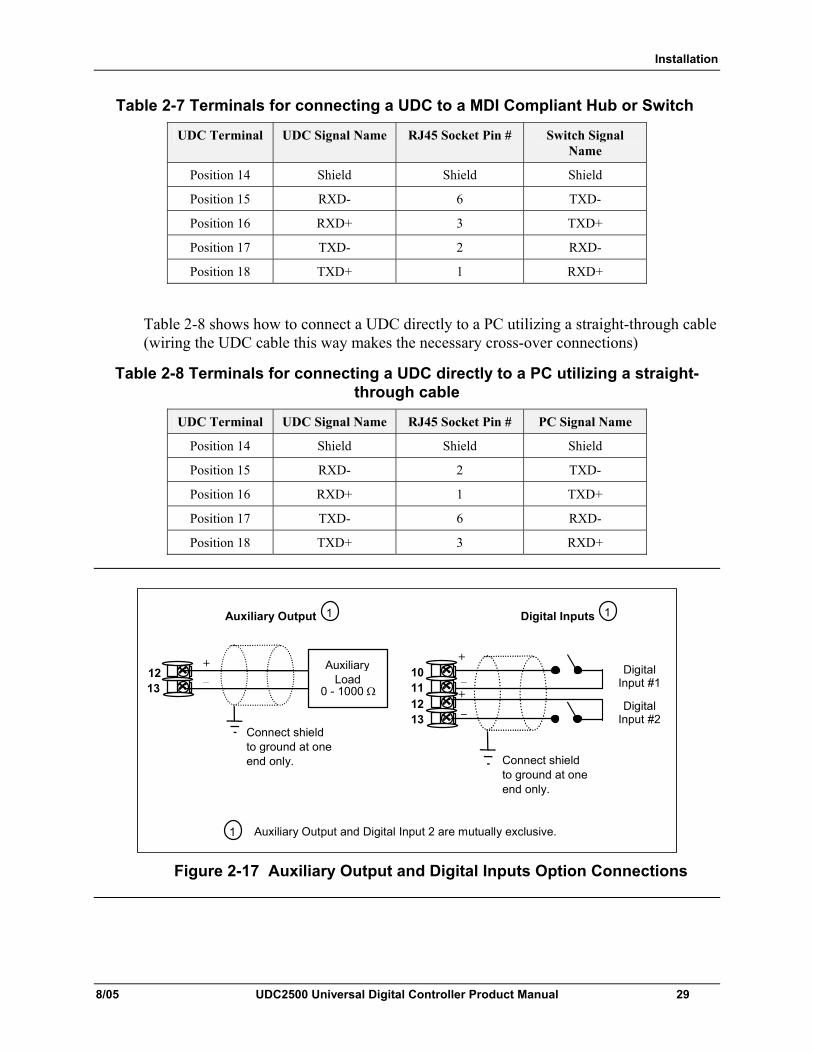
Installation
8/05 UDC2500 Universal Digital Controller Product Manual 29
Table 2-7 Terminals for connecting a UDC to a MDI Compliant Hub or Switch
UDC Terminal UDC Signal Name RJ45 Socket Pin # Switch Signal Name
Position 14 Shield Shield Shield
Position 15 RXD- 6 TXD-
Position 16 RXD+ 3 TXD+
Position 17 TXD- 2 RXD-
Position 18 TXD+ 1 RXD+
Table 2-8 shows how to connect a UDC directly to a PC utilizing a straight-through cable (wiring the UDC cable this way makes the necessary cross-over connections)
Table 2-8 Terminals for connecting a UDC directly to a PC utilizing a straight-through cable
UDC Terminal UDC Signal Name RJ45 Socket Pin # PC Signal Name
Position 14 Shield Shield Shield
Position 15 RXD- 2 TXD-
Position 16 RXD+ 1 TXD+
Position 17 TXD- 6 RXD-
Position 18 TXD+ 3 RXD+
12 13
+ _
Auxiliary Load
0 - 1000 Ω
Connect shield to ground at one end only.
1
1 Auxiliary Output and Digital Input 2 are mutually exclusive.
Auxiliary Output
10 11
+
_ Digital Input #1
Connect shield to ground at one end only.
Digital Inputs 1
12 13
+ _ Digital
Input #2
Figure 2-17 Auxiliary Output and Digital Inputs Option Connections
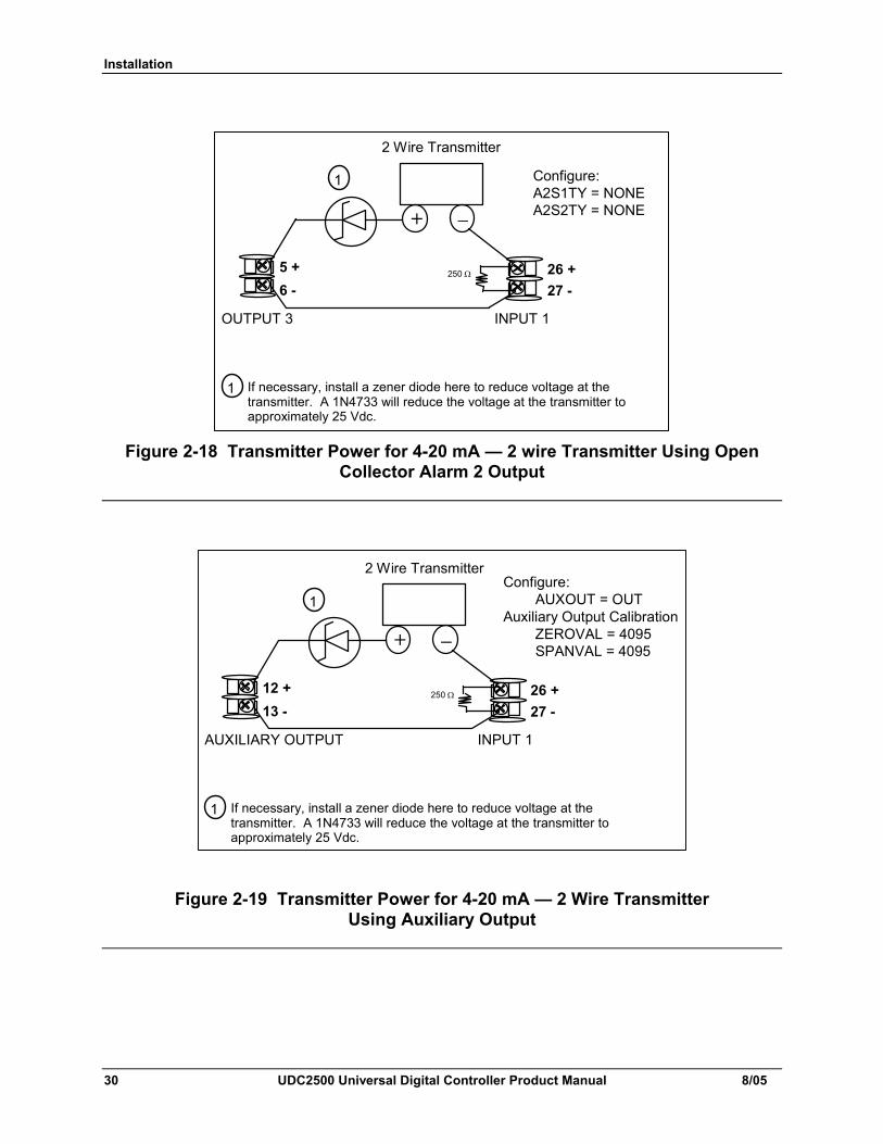
Installation
30 UDC2500 Universal Digital Controller Product Manual 8/05
Configure:A2S1TY = NONE A2S2TY = NONE
2 Wire Transmitter
_ +
INPUT 1OUTPUT 3
250 Ω 26 +27 -
5 + 6 -
If necessary, install a zener diode here to reduce voltage at the transmitter. A 1N4733 will reduce the voltage at the transmitter to approximately 25 Vdc.
1
1
Figure 2-18 Transmitter Power for 4-20 mA — 2 wire Transmitter Using Open Collector Alarm 2 Output
2 Wire Transmitter
_ +
INPUT 1AUXILIARY OUTPUT
250 Ω 26 +27 -
12 + 13 -
Configure: AUXOUT = OUT Auxiliary Output Calibration ZEROVAL = 4095 SPANVAL = 4095
If necessary, install a zener diode here to reduce voltage at the transmitter. A 1N4733 will reduce the voltage at the transmitter to approximately 25 Vdc.
1
1
Figure 2-19 Transmitter Power for 4-20 mA — 2 Wire Transmitter Using Auxiliary Output
Configuration
8/05 UDC2500 Universal Digital Controller Product Manual 31
3 Configuration
3.1 Overview
Introduction Configuration is a dedicated operation where you use straightforward keystroke sequences to select and establish (configure) pertinent control data best suited for your application.
To assist you in the configuration process, there are prompts that appear in the upper and lower displays. These prompts let you know what group of configuration data (Set Up prompts) you are working with and also, the specific parameters (Function prompts) associated with each group.
Table 3-1 shows an overview of the prompt hierarchy as it appears in the controller.
What’s in this section? The following topics are covered in this section.
Table 3-1 Configuration Topics TOPIC See Page
3.1 Overview 31 3.2 Configuration Prompt Hierarchy 32 3.3 Configuration Procedure 33 3.4 Tuning Set Up Group 34 3.5 SP Ramp Set Up Group 38 3.6 Accutune Set Up Group 42 3.7 Algorithm Set Up Group 45 3.8 Output Set Up Group 50 3.9 Input 1 Set Up Group 54 3.10 Input 2 Set Up Group 58 3.11 Control Set Up Group 60 3.12 Options Set Up Group 66 3.13 Communications Set Up Group 72 3.14 Alarms Set Up Group 75 3.15 Display Set Up Group 81 3.16 Configuration Record Sheet 83
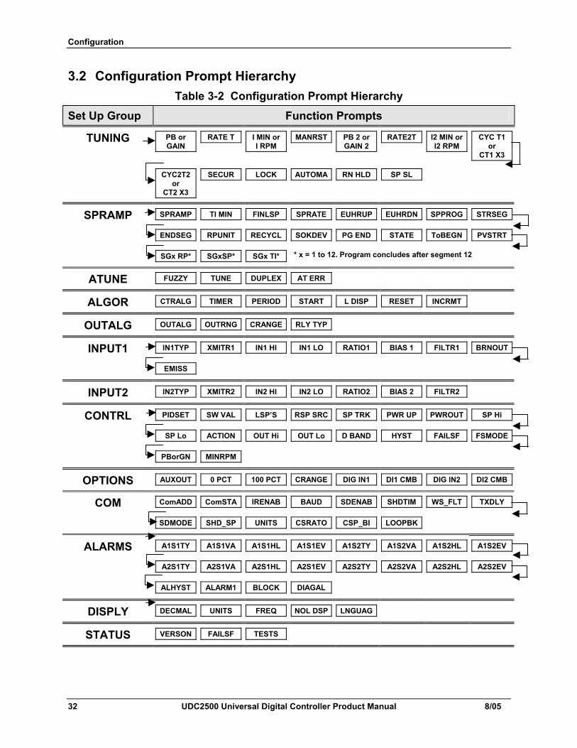
Configuration
32 UDC2500 Universal Digital Controller Product Manual 8/05
3.2 Configuration Prompt Hierarchy Table 3-2 Configuration Prompt Hierarchy
Set Up Group Function Prompts
TUNING PB or GAIN
RATE T I MIN or I RPM
MANRST PB 2 or GAIN 2
RATE2T I2 MIN or I2 RPM
CYC T1 or
CT1 X3
CYC2T2 or
CT2 X3
SECUR LOCK AUTOMA RN HLD SP SL
SPRAMP SPRAMP TI MIN FINLSP SPRATE EUHRUP EUHRDN SPPROG STRSEG
ENDSEG RPUNIT RECYCL SOKDEV PG END STATE ToBEGN PVSTRT
SGx RP* SGxSP* SGx TI* * x = 1 to 12. Program concludes after segment 12
ATUNE FUZZY TUNE DUPLEX AT ERR
ALGOR CTRALG TIMER PERIOD START L DISP RESET INCRMT
OUTALG OUTALG OUTRNG CRANGE RLY TYP
INPUT1 IN1TYP XMITR1 IN1 HI IN1 LO RATIO1 BIAS 1 FILTR1 BRNOUT
EMISS
INPUT2 IN2TYP XMITR2 IN2 HI IN2 LO RATIO2 BIAS 2 FILTR2
CONTRL PIDSET SW VAL LSP’S RSP SRC SP TRK PWR UP PWROUT SP Hi
SP Lo ACTION OUT Hi OUT Lo D BAND HYST FAILSF FSMODE
PBorGN MINRPM
OPTIONS AUXOUT 0 PCT 100 PCT CRANGE DIG IN1 DI1 CMB DIG IN2 DI2 CMB
COM ComADD ComSTA IRENAB BAUD SDENAB SHDTIM WS_FLT TXDLY
SDMODE SHD_SP UNITS CSRATO CSP_BI LOOPBK
ALARMS A1S1TY A1S1VA A1S1HL A1S1EV A1S2TY A1S2VA A1S2HL A1S2EV
A2S1TY A2S1VA A2S1HL A2S1EV A2S2TY A2S2VA A2S2HL A2S2EV
ALHYST ALARM1 BLOCK DIAGAL
DISPLY DECMAL UNITS FREQ NOL DSP LNGUAG
STATUS VERSON FAILSF TESTS
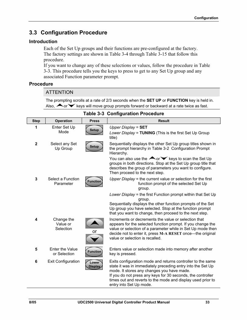
Configuration
8/05 UDC2500 Universal Digital Controller Product Manual 33
3.3 Configuration Procedure Introduction
Each of the Set Up groups and their functions are pre-configured at the factory. The factory settings are shown in Table 3-4 through Table 3-15 that follow this procedure. If you want to change any of these selections or values, follow the procedure in Table 3-3. This procedure tells you the keys to press to get to any Set Up group and any associated Function parameter prompt.
Procedure ATTENTION The prompting scrolls at a rate of 2/3 seconds when the SET UP or FUNCTION key is held in. Also, or keys will move group prompts forward or backward at a rate twice as fast.
Table 3-3 Configuration Procedure Step Operation Press Result
1 Enter Set Up Mode SetupSetup
Upper Display = SET Lower Display = TUNING (This is the first Set Up Group title)
2 Select any Set Up Group SetupSetup
Sequentially displays the other Set Up group titles shown in the prompt hierarchy in Table 3-2 Configuration Prompt Hierarchy. You can also use the or keys to scan the Set Up groups in both directions. Stop at the Set Up group title that describes the group of parameters you want to configure. Then proceed to the next step.
3 Select a Function Parameter FunctionFunctionFunction
Upper Display = the current value or selection for the first function prompt of the selected Set Up group.
Lower Display = the first Function prompt within that Set Up group.
Sequentially displays the other function prompts of the Set Up group you have selected. Stop at the function prompt that you want to change, then proceed to the next step.
4 Change the Value or Selection or
Increments or decrements the value or selection that appears for the selected function prompt. If you change the value or selection of a parameter while in Set Up mode then decide not to enter it, press M-A RESET once—the original value or selection is recalled.
5 Enter the Value or Selection FunctionFunctionFunction
Enters value or selection made into memory after another key is pressed.
6 Exit Configuration LowerDisplayLower
DisplayLower
Display
Exits configuration mode and returns controller to the same state it was in immediately preceding entry into the Set Up mode. It stores any changes you have made. If you do not press any keys for 30 seconds, the controller times out and reverts to the mode and display used prior to entry into Set Up mode.
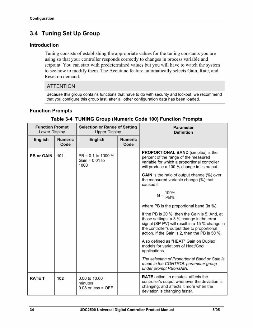
Configuration
34 UDC2500 Universal Digital Controller Product Manual 8/05
3.4 Tuning Set Up Group
Introduction Tuning consists of establishing the appropriate values for the tuning constants you are using so that your controller responds correctly to changes in process variable and setpoint. You can start with predetermined values but you will have to watch the system to see how to modify them. The Accutune feature automatically selects Gain, Rate, and Reset on demand.
ATTENTION Because this group contains functions that have to do with security and lockout, we recommend that you configure this group last, after all other configuration data has been loaded.
Function Prompts Table 3-4 TUNING Group (Numeric Code 100) Function Prompts
Function Prompt Lower Display
Selection or Range of Setting Upper Display
English Numeric Code
English Numeric Code
Parameter Definition
PB or GAIN 101 PB = 0.1 to 1000 %Gain = 0.01 to 1000
PROPORTIONAL BAND (simplex) is the percent of the range of the measured variable for which a proportional controller will produce a 100 % change in its output.
GAIN is the ratio of output change (%) over the measured variable change (%) that caused it.
G = 100%PB%
where PB is the proportional band (in %)
If the PB is 20 %, then the Gain is 5. And, at those settings, a 3 % change in the error signal (SP-PV) will result in a 15 % change in the controller's output due to proportional action. If the Gain is 2, then the PB is 50 %.
Also defined as "HEAT" Gain on Duplex models for variations of Heat/Cool applications.
The selection of Proportional Band or Gain is made in the CONTROL parameter group under prompt PBorGAIN.
RATE T 102 0.00 to 10.00 minutes 0.08 or less = OFF
RATE action, in minutes, affects the controller's output whenever the deviation is changing; and affects it more when the deviation is changing faster.
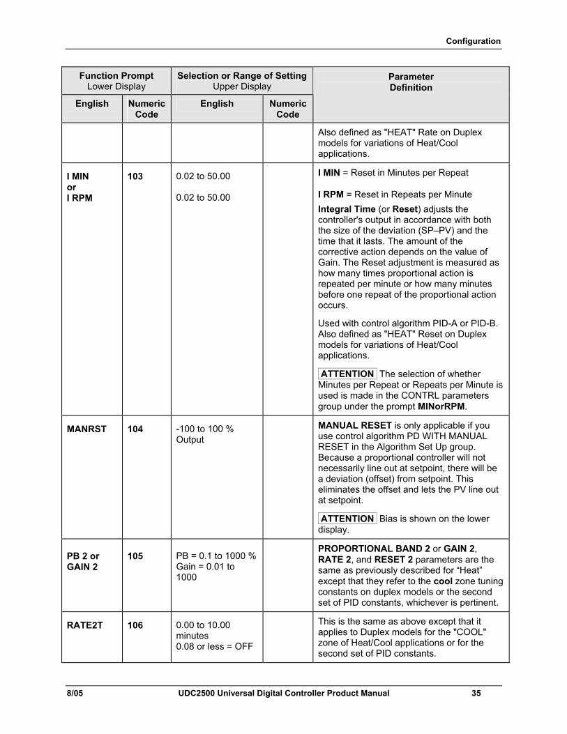
Configuration
8/05 UDC2500 Universal Digital Controller Product Manual 35
Function Prompt Lower Display
Selection or Range of Setting Upper Display
English Numeric Code
English Numeric Code
Parameter Definition
Also defined as "HEAT" Rate on Duplex models for variations of Heat/Cool applications.
I MIN or I RPM
103 0.02 to 50.00 0.02 to 50.00
I MIN = Reset in Minutes per Repeat I RPM = Reset in Repeats per Minute Integral Time (or Reset) adjusts the controller's output in accordance with both the size of the deviation (SP–PV) and the time that it lasts. The amount of the corrective action depends on the value of Gain. The Reset adjustment is measured as how many times proportional action is repeated per minute or how many minutes before one repeat of the proportional action occurs.
Used with control algorithm PID-A or PID-B. Also defined as "HEAT" Reset on Duplex models for variations of Heat/Cool applications.
ATTENTION The selection of whether Minutes per Repeat or Repeats per Minute is used is made in the CONTRL parameters group under the prompt MINorRPM.
MANRST 104 -100 to 100 % Output
MANUAL RESET is only applicable if you use control algorithm PD WITH MANUAL RESET in the Algorithm Set Up group. Because a proportional controller will not necessarily line out at setpoint, there will be a deviation (offset) from setpoint. This eliminates the offset and lets the PV line out at setpoint.
ATTENTION Bias is shown on the lower display.
PB 2 or GAIN 2
105 PB = 0.1 to 1000 %Gain = 0.01 to 1000
PROPORTIONAL BAND 2 or GAIN 2, RATE 2, and RESET 2 parameters are the same as previously described for “Heat” except that they refer to the cool zone tuning constants on duplex models or the second set of PID constants, whichever is pertinent.
RATE2T 106 0.00 to 10.00 minutes 0.08 or less = OFF
This is the same as above except that it applies to Duplex models for the "COOL" zone of Heat/Cool applications or for the second set of PID constants.
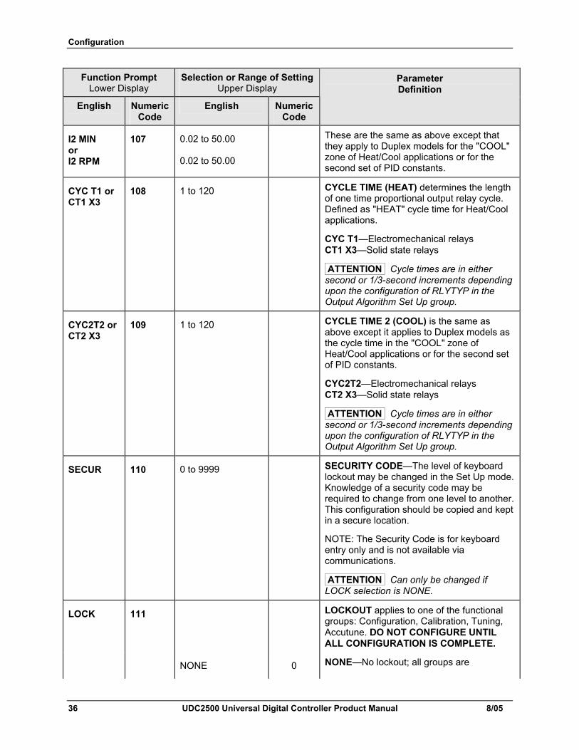
Configuration
36 UDC2500 Universal Digital Controller Product Manual 8/05
Function Prompt Lower Display
Selection or Range of Setting Upper Display
English Numeric Code
English Numeric Code
Parameter Definition
I2 MIN or I2 RPM
107 0.02 to 50.00 0.02 to 50.00
These are the same as above except that they apply to Duplex models for the "COOL" zone of Heat/Cool applications or for the second set of PID constants.
CYC T1 or CT1 X3
108 1 to 120 CYCLE TIME (HEAT) determines the length of one time proportional output relay cycle. Defined as "HEAT" cycle time for Heat/Cool applications.
CYC T1—Electromechanical relays CT1 X3—Solid state relays
ATTENTION Cycle times are in either second or 1/3-second increments depending upon the configuration of RLYTYP in the Output Algorithm Set Up group.
CYC2T2 or CT2 X3
109 1 to 120 CYCLE TIME 2 (COOL) is the same as above except it applies to Duplex models as the cycle time in the "COOL" zone of Heat/Cool applications or for the second set of PID constants.
CYC2T2—Electromechanical relays CT2 X3—Solid state relays
ATTENTION Cycle times are in either second or 1/3-second increments depending upon the configuration of RLYTYP in the Output Algorithm Set Up group.
SECUR 110 0 to 9999 SECURITY CODE—The level of keyboard lockout may be changed in the Set Up mode. Knowledge of a security code may be required to change from one level to another. This configuration should be copied and kept in a secure location.
NOTE: The Security Code is for keyboard entry only and is not available via communications.
ATTENTION Can only be changed if LOCK selection is NONE.
LOCK 111 LOCKOUT applies to one of the functional groups: Configuration, Calibration, Tuning, Accutune. DO NOT CONFIGURE UNTIL ALL CONFIGURATION IS COMPLETE.
NONE 0 NONE—No lockout; all groups are
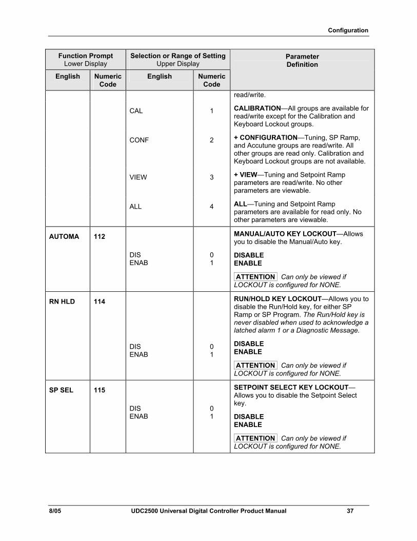
Configuration
8/05 UDC2500 Universal Digital Controller Product Manual 37
Function Prompt Lower Display
Selection or Range of Setting Upper Display
English Numeric Code
English Numeric Code
Parameter Definition
read/write.
CAL 1 CALIBRATION—All groups are available for read/write except for the Calibration and Keyboard Lockout groups.
CONF 2 + CONFIGURATION—Tuning, SP Ramp, and Accutune groups are read/write. All other groups are read only. Calibration and Keyboard Lockout groups are not available.
VIEW 3 + VIEW—Tuning and Setpoint Ramp parameters are read/write. No other parameters are viewable.
ALL 4 ALL—Tuning and Setpoint Ramp parameters are available for read only. No other parameters are viewable.
AUTOMA 112 DIS ENAB
0 1
MANUAL/AUTO KEY LOCKOUT—Allows you to disable the Manual/Auto key.
DISABLE ENABLE
ATTENTION Can only be viewed if LOCKOUT is configured for NONE.
RN HLD 114
DIS ENAB
0 1
RUN/HOLD KEY LOCKOUT—Allows you to disable the Run/Hold key, for either SP Ramp or SP Program. The Run/Hold key is never disabled when used to acknowledge a latched alarm 1 or a Diagnostic Message.
DISABLE ENABLE
ATTENTION Can only be viewed if LOCKOUT is configured for NONE.
SP SEL 115
DIS ENAB
0 1
SETPOINT SELECT KEY LOCKOUT—Allows you to disable the Setpoint Select key.
DISABLE ENABLE
ATTENTION Can only be viewed if LOCKOUT is configured for NONE.
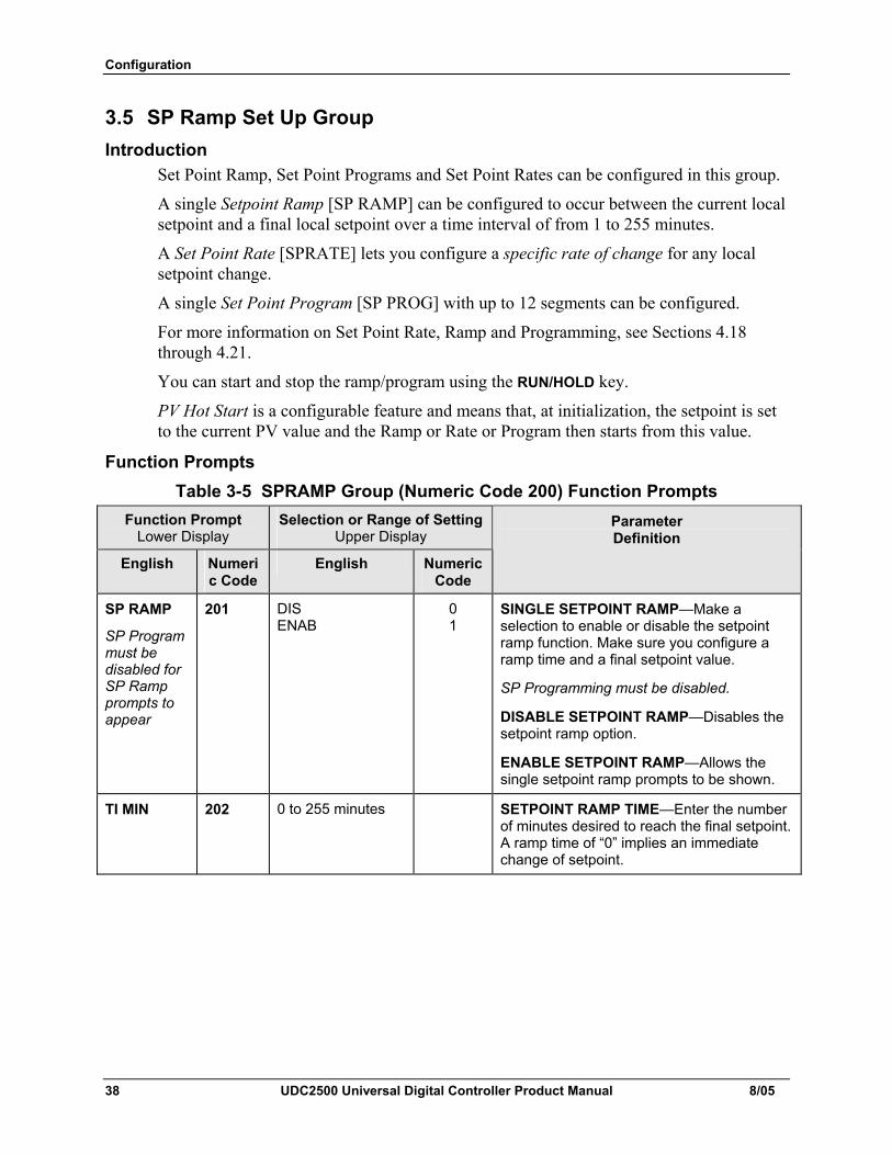
Configuration
38 UDC2500 Universal Digital Controller Product Manual 8/05
3.5 SP Ramp Set Up Group Introduction
Set Point Ramp, Set Point Programs and Set Point Rates can be configured in this group.
A single Setpoint Ramp [SP RAMP] can be configured to occur between the current local setpoint and a final local setpoint over a time interval of from 1 to 255 minutes.
A Set Point Rate [SPRATE] lets you configure a specific rate of change for any local setpoint change.
A single Set Point Program [SP PROG] with up to 12 segments can be configured.
For more information on Set Point Rate, Ramp and Programming, see Sections 4.18 through 4.21.
You can start and stop the ramp/program using the RUN/HOLD key.
PV Hot Start is a configurable feature and means that, at initialization, the setpoint is set to the current PV value and the Ramp or Rate or Program then starts from this value.
Function Prompts Table 3-5 SPRAMP Group (Numeric Code 200) Function Prompts
Function Prompt Lower Display
Selection or Range of Setting Upper Display
English Numeric Code
English Numeric Code
Parameter Definition
SP RAMP
SP Program must be disabled for SP Ramp prompts to appear
201 DIS ENAB
0 1
SINGLE SETPOINT RAMP—Make a selection to enable or disable the setpoint ramp function. Make sure you configure a ramp time and a final setpoint value.
SP Programming must be disabled.
DISABLE SETPOINT RAMP—Disables the setpoint ramp option.
ENABLE SETPOINT RAMP—Allows the single setpoint ramp prompts to be shown.
TI MIN 202 0 to 255 minutes SETPOINT RAMP TIME—Enter the number of minutes desired to reach the final setpoint. A ramp time of “0” implies an immediate change of setpoint.
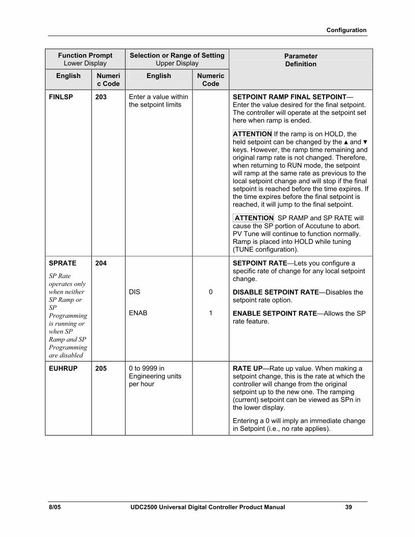
Configuration
8/05 UDC2500 Universal Digital Controller Product Manual 39
Function Prompt Lower Display
Selection or Range of Setting Upper Display
English Numeric Code
English Numeric Code
Parameter Definition
FINLSP 203 Enter a value within the setpoint limits
SETPOINT RAMP FINAL SETPOINT—Enter the value desired for the final setpoint. The controller will operate at the setpoint set here when ramp is ended.
ATTENTION If the ramp is on HOLD, the held setpoint can be changed by the and keys. However, the ramp time remaining and original ramp rate is not changed. Therefore, when returning to RUN mode, the setpoint will ramp at the same rate as previous to the local setpoint change and will stop if the final setpoint is reached before the time expires. If the time expires before the final setpoint is reached, it will jump to the final setpoint.
ATTENTION SP RAMP and SP RATE will cause the SP portion of Accutune to abort. PV Tune will continue to function normally. Ramp is placed into HOLD while tuning (TUNE configuration).
SPRATE
SP Rate operates only when neither SP Ramp or SP Programming is running or when SP Ramp and SP Programming are disabled
204
DIS
ENAB
0
1
SETPOINT RATE—Lets you configure a specific rate of change for any local setpoint change.
DISABLE SETPOINT RATE—Disables the setpoint rate option.
ENABLE SETPOINT RATE—Allows the SP rate feature.
EUHRUP 205 0 to 9999 in Engineering units per hour
RATE UP—Rate up value. When making a setpoint change, this is the rate at which the controller will change from the original setpoint up to the new one. The ramping (current) setpoint can be viewed as SPn in the lower display.
Entering a 0 will imply an immediate change in Setpoint (i.e., no rate applies).
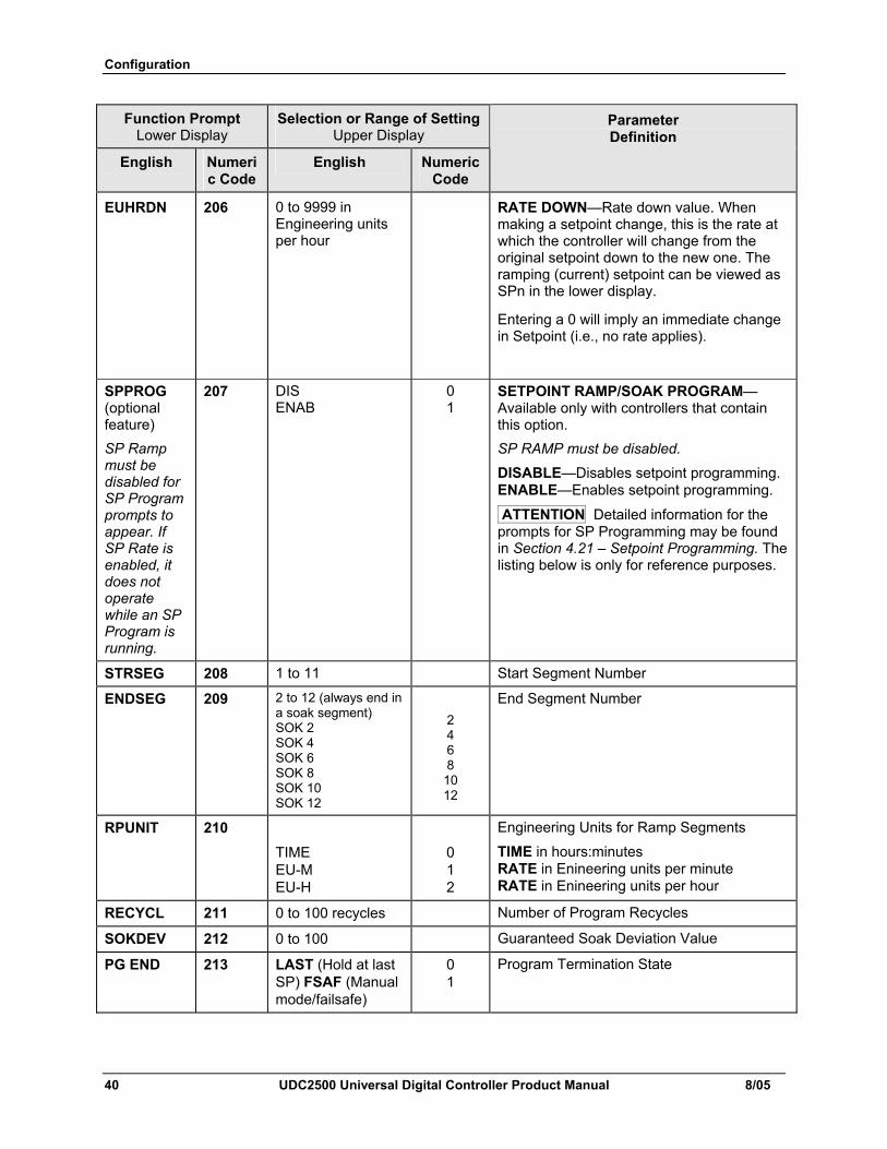
Configuration
40 UDC2500 Universal Digital Controller Product Manual 8/05
Function Prompt Lower Display
Selection or Range of Setting Upper Display
English Numeric Code
English Numeric Code
Parameter Definition
EUHRDN 206 0 to 9999 in Engineering units per hour
RATE DOWN—Rate down value. When making a setpoint change, this is the rate at which the controller will change from the original setpoint down to the new one. The ramping (current) setpoint can be viewed as SPn in the lower display.
Entering a 0 will imply an immediate change in Setpoint (i.e., no rate applies).
SPPROG (optional feature) SP Ramp must be disabled for SP Program prompts to appear. If SP Rate is enabled, it does not operate while an SP Program is running.
207 DIS ENAB
0 1
SETPOINT RAMP/SOAK PROGRAM—Available only with controllers that contain this option. SP RAMP must be disabled. DISABLE—Disables setpoint programming. ENABLE—Enables setpoint programming.
ATTENTION Detailed information for the prompts for SP Programming may be found in Section 4.21 – Setpoint Programming. The listing below is only for reference purposes.
STRSEG 208 1 to 11 Start Segment Number
ENDSEG 209 2 to 12 (always end in a soak segment) SOK 2 SOK 4 SOK 6 SOK 8 SOK 10 SOK 12
2 4 6 8 10 12
End Segment Number
RPUNIT 210
TIME EU-M EU-H
0 1 2
Engineering Units for Ramp Segments
TIME in hours:minutes RATE in Enineering units per minute RATE in Enineering units per hour
RECYCL 211 0 to 100 recycles Number of Program Recycles
SOKDEV 212 0 to 100 Guaranteed Soak Deviation Value
PG END 213 LAST (Hold at last SP) FSAF (Manual mode/failsafe)
0 1
Program Termination State
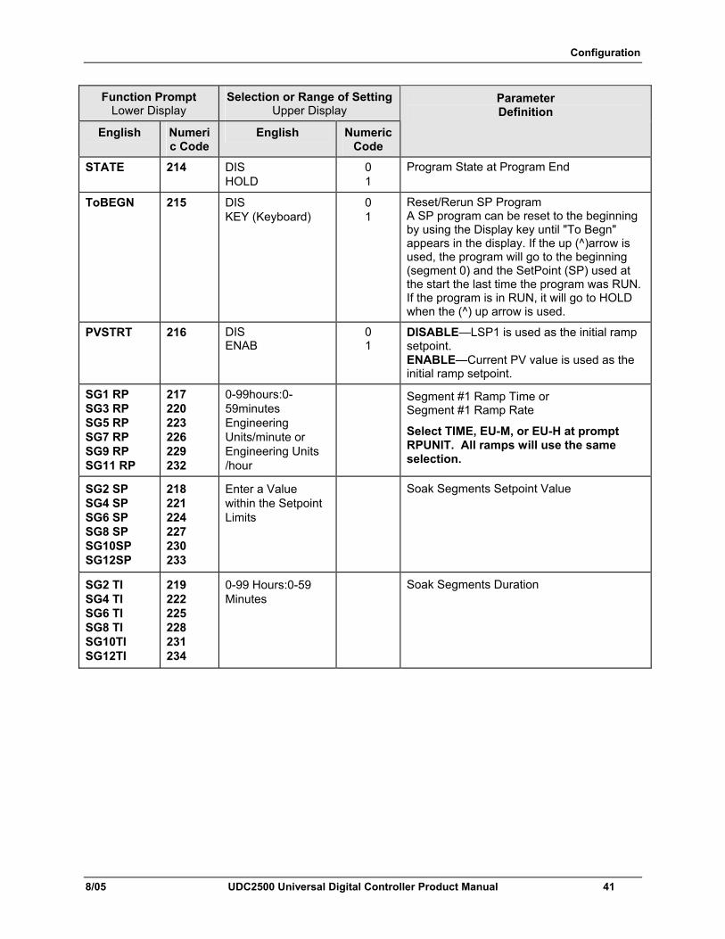
Configuration
8/05 UDC2500 Universal Digital Controller Product Manual 41
Function Prompt Lower Display
Selection or Range of Setting Upper Display
English Numeric Code
English Numeric Code
Parameter Definition
STATE 214 DIS HOLD
0 1
Program State at Program End
ToBEGN 215 DIS KEY (Keyboard)
0 1
Reset/Rerun SP Program A SP program can be reset to the beginning by using the Display key until "To Begn" appears in the display. If the up (^)arrow is used, the program will go to the beginning (segment 0) and the SetPoint (SP) used at the start the last time the program was RUN. If the program is in RUN, it will go to HOLD when the (^) up arrow is used.
PVSTRT 216 DIS ENAB
0 1
DISABLE—LSP1 is used as the initial ramp setpoint. ENABLE—Current PV value is used as the initial ramp setpoint.
SG1 RP SG3 RP SG5 RP SG7 RP SG9 RP SG11 RP
217 220 223 226 229 232
0-99hours:0-59minutes Engineering Units/minute or Engineering Units /hour
Segment #1 Ramp Time or Segment #1 Ramp Rate
Select TIME, EU-M, or EU-H at prompt RPUNIT. All ramps will use the same selection.
SG2 SP SG4 SP SG6 SP SG8 SP SG10SP SG12SP
218 221 224 227 230 233
Enter a Value within the Setpoint Limits
Soak Segments Setpoint Value
SG2 TI SG4 TI SG6 TI SG8 TI SG10TI SG12TI
219 222 225 228 231 234
0-99 Hours:0-59 Minutes
Soak Segments Duration
Configuration
42 UDC2500 Universal Digital Controller Product Manual 8/05
3.6 Accutune Set Up Group
Introduction Accutune III automatically calculates GAIN, RATE, and RESET TIME (PID) tuning constants for your control loop. When initiated on demand, the Accutune algorithm measures a process step response and automatically generates the PID tuning constants needed for no overshoot on your process. Fuzzy, Fuzzy Overshoot Suppression: When enabled, this configuration will suppress or eliminate any overshoot that may occur as a result of the existing tuning parameters, as the PV approaches the setpoint. Tune, Demand Tuning: The tuning process is initiated through the operator interface keys or via a digital input (if configured). The algorithm then calculates new tuning parameters and enters them in the tuning group. Tune will operate with PIDA, PIDB, PD+MR and Three Position Step Control algorithms. SP, SP Tuning: SP tuning continuously adjusts the PID parameters in response to setpoint changes. You can select tuning on minimum setpoint changes of 5 % up to 15 % span. Perform SP tuning after you have configured the controller. SP Tuning does not operate with the Three Position Step Control algorithm. Simplex Tuning is used when a Simplex Control Algorithm is configured and uses the current SP value and alters the output over the Output Limit Range. Duplex Tuning is used when a Duplex Control Algorithm is configured. To perform a Duplex Tune, Two Local Setpoints must be configured per the Control Group in Section 3.11.
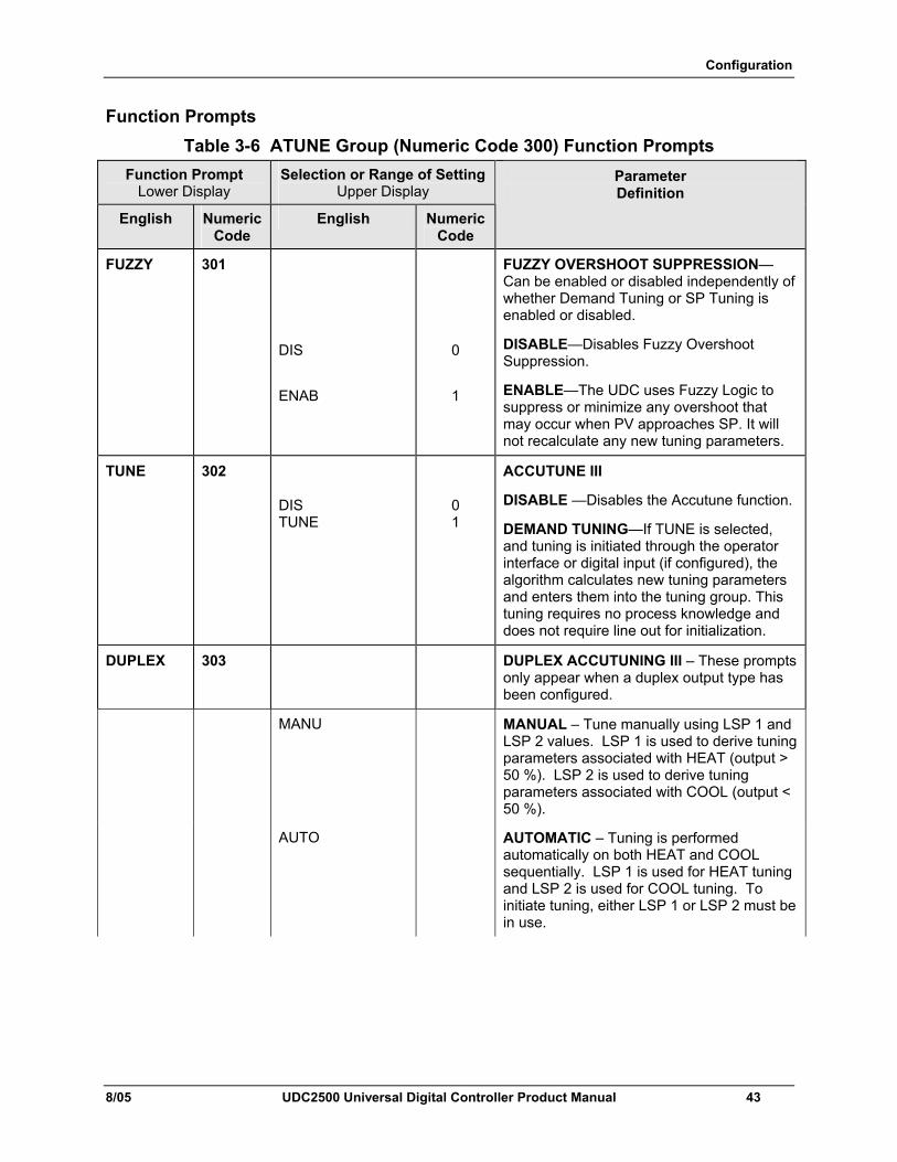
Configuration
8/05 UDC2500 Universal Digital Controller Product Manual 43
Function Prompts Table 3-6 ATUNE Group (Numeric Code 300) Function Prompts
Function Prompt Lower Display
Selection or Range of Setting Upper Display
English Numeric Code
English Numeric Code
Parameter Definition
FUZZY 301
DIS
ENAB
0
1
FUZZY OVERSHOOT SUPPRESSION—Can be enabled or disabled independently of whether Demand Tuning or SP Tuning is enabled or disabled.
DISABLE—Disables Fuzzy Overshoot Suppression.
ENABLE—The UDC uses Fuzzy Logic to suppress or minimize any overshoot that may occur when PV approaches SP. It will not recalculate any new tuning parameters.
TUNE 302
DIS TUNE
0 1
ACCUTUNE III
DISABLE —Disables the Accutune function.
DEMAND TUNING—If TUNE is selected, and tuning is initiated through the operator interface or digital input (if configured), the algorithm calculates new tuning parameters and enters them into the tuning group. This tuning requires no process knowledge and does not require line out for initialization.
DUPLEX 303 DUPLEX ACCUTUNING III – These prompts only appear when a duplex output type has been configured.
MANU
MANUAL – Tune manually using LSP 1 and LSP 2 values. LSP 1 is used to derive tuning parameters associated with HEAT (output > 50 %). LSP 2 is used to derive tuning parameters associated with COOL (output < 50 %).
AUTO
AUTOMATIC – Tuning is performed automatically on both HEAT and COOL sequentially. LSP 1 is used for HEAT tuning and LSP 2 is used for COOL tuning. To initiate tuning, either LSP 1 or LSP 2 must be in use.
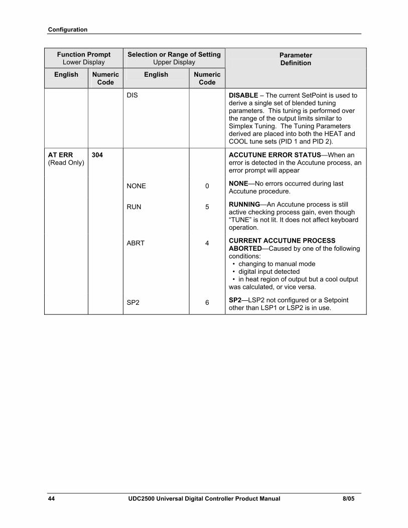
Configuration
44 UDC2500 Universal Digital Controller Product Manual 8/05
Function Prompt Lower Display
Selection or Range of Setting Upper Display
English Numeric Code
English Numeric Code
Parameter Definition
DIS DISABLE – The current SetPoint is used to derive a single set of blended tuning parameters. This tuning is performed over the range of the output limits similar to Simplex Tuning. The Tuning Parameters derived are placed into both the HEAT and COOL tune sets (PID 1 and PID 2).
AT ERR (Read Only)
304 ACCUTUNE ERROR STATUS—When an error is detected in the Accutune process, an error prompt will appear
NONE 0 NONE—No errors occurred during last Accutune procedure.
RUN 5 RUNNING—An Accutune process is still active checking process gain, even though “TUNE” is not lit. It does not affect keyboard operation.
ABRT 4 CURRENT ACCUTUNE PROCESS ABORTED—Caused by one of the following conditions: • changing to manual mode • digital input detected • in heat region of output but a cool output was calculated, or vice versa.
SP2 6 SP2—LSP2 not configured or a Setpoint other than LSP1 or LSP2 is in use.
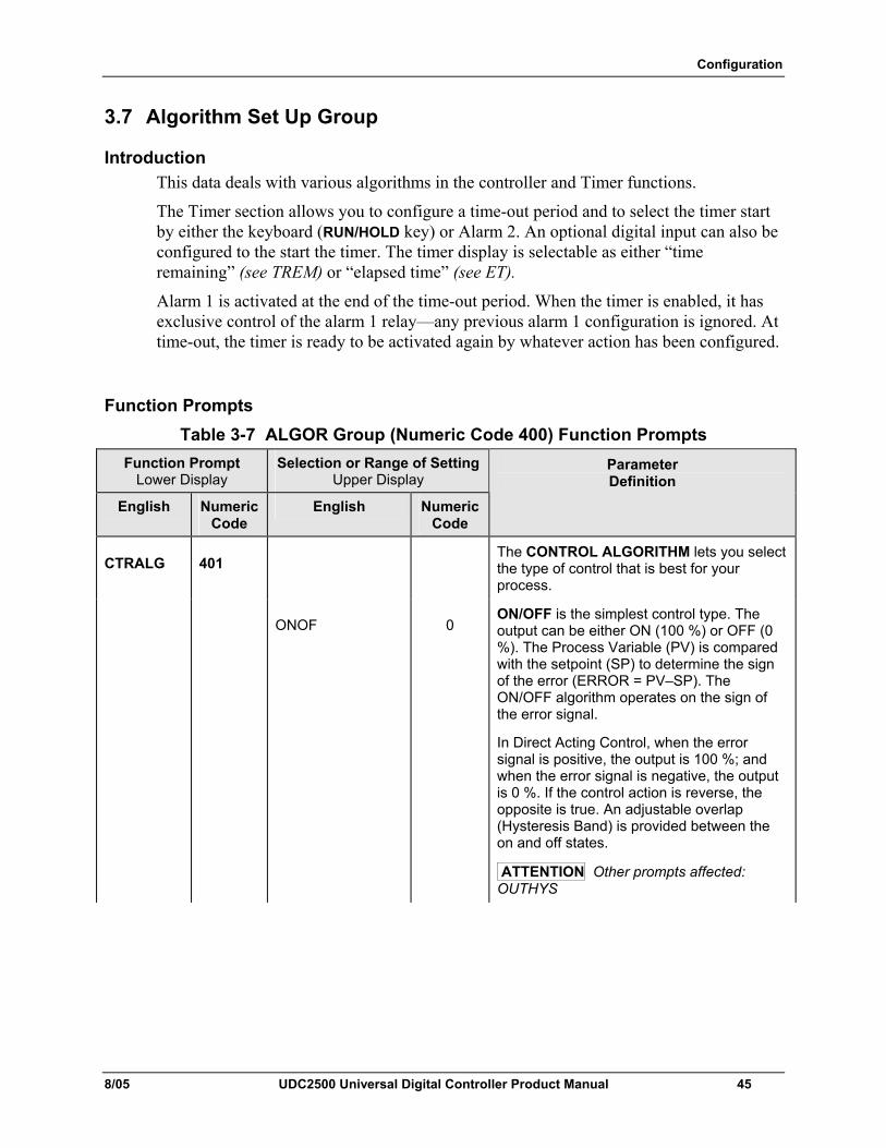
Configuration
8/05 UDC2500 Universal Digital Controller Product Manual 45
3.7 Algorithm Set Up Group
Introduction This data deals with various algorithms in the controller and Timer functions.
The Timer section allows you to configure a time-out period and to select the timer start by either the keyboard (RUN/HOLD key) or Alarm 2. An optional digital input can also be configured to the start the timer. The timer display is selectable as either “time remaining” (see TREM) or “elapsed time” (see ET).
Alarm 1 is activated at the end of the time-out period. When the timer is enabled, it has exclusive control of the alarm 1 relay—any previous alarm 1 configuration is ignored. At time-out, the timer is ready to be activated again by whatever action has been configured.
Function Prompts Table 3-7 ALGOR Group (Numeric Code 400) Function Prompts
Function Prompt Lower Display
Selection or Range of Setting Upper Display
English Numeric Code
English Numeric Code
Parameter Definition
CTRALG 401 The CONTROL ALGORITHM lets you select the type of control that is best for your process.
ONOF 0 ON/OFF is the simplest control type. The output can be either ON (100 %) or OFF (0 %). The Process Variable (PV) is compared with the setpoint (SP) to determine the sign of the error (ERROR = PV–SP). The ON/OFF algorithm operates on the sign of the error signal.
In Direct Acting Control, when the error signal is positive, the output is 100 %; and when the error signal is negative, the output is 0 %. If the control action is reverse, the opposite is true. An adjustable overlap (Hysteresis Band) is provided between the on and off states.
ATTENTION Other prompts affected: OUTHYS
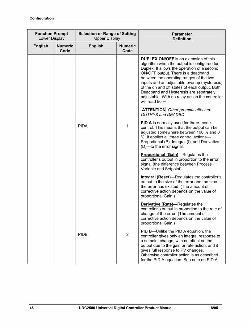
Configuration
46 UDC2500 Universal Digital Controller Product Manual 8/05
Function Prompt Lower Display
Selection or Range of Setting Upper Display
English Numeric Code
English Numeric Code
Parameter Definition
DUPLEX ON/OFF is an extension of this algorithm when the output is configured for Duplex. It allows the operation of a second ON/OFF output. There is a deadband between the operating ranges of the two inputs and an adjustable overlap (hysteresis) of the on and off states of each output. Both Deadband and Hysteresis are separately adjustable. With no relay action the controller will read 50 %.
ATTENTION Other prompts affected: OUTHYS and DEADBD
PIDA 1 PID A is normally used for three-mode control. This means that the output can be adjusted somewhere between 100 % and 0 %. It applies all three control actions—Proportional (P), Integral (I), and Derivative (D)—to the error signal.
Proportional (Gain)—Regulates the controller’s output in proportion to the error signal (the difference between Process Variable and Setpoint).
Integral (Reset)—Regulates the controller’s output to the size of the error and the time the error has existed. (The amount of corrective action depends on the value of proportional Gain.)
Derivative (Rate)—Regulates the controller’s output in proportion to the rate of change of the error. (The amount of corrective action depends on the value of proportional Gain.)
PIDB 2 PID B—Unlike the PID A equation, the controller gives only an integral response to a setpoint change, with no effect on the output due to the gain or rate action, and it gives full response to PV changes. Otherwise controller action is as described for the PID A equation. See note on PID A.
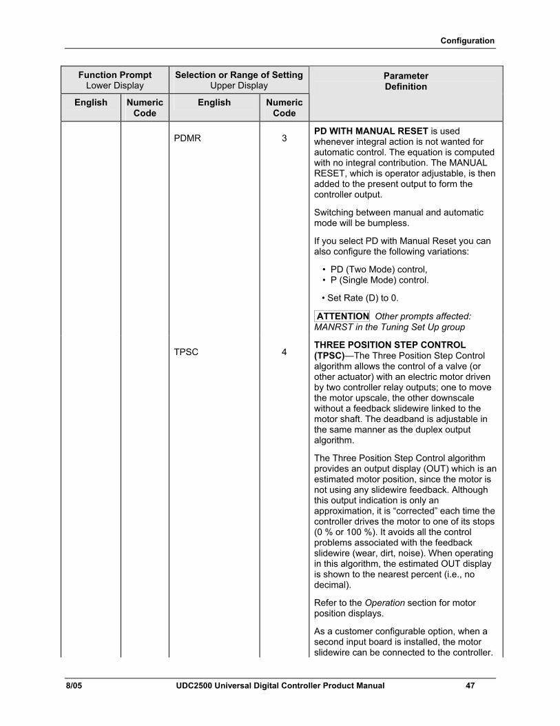
Configuration
8/05 UDC2500 Universal Digital Controller Product Manual 47
Function Prompt Lower Display
Selection or Range of Setting Upper Display
English Numeric Code
English Numeric Code
Parameter Definition
PDMR 3 PD WITH MANUAL RESET is used whenever integral action is not wanted for automatic control. The equation is computed with no integral contribution. The MANUAL RESET, which is operator adjustable, is then added to the present output to form the controller output.
Switching between manual and automatic mode will be bumpless.
If you select PD with Manual Reset you can also configure the following variations:
• PD (Two Mode) control, • P (Single Mode) control.
• Set Rate (D) to 0.
ATTENTION Other prompts affected: MANRST in the Tuning Set Up group
TPSC 4 THREE POSITION STEP CONTROL (TPSC)—The Three Position Step Control algorithm allows the control of a valve (or other actuator) with an electric motor driven by two controller relay outputs; one to move the motor upscale, the other downscale without a feedback slidewire linked to the motor shaft. The deadband is adjustable in the same manner as the duplex output algorithm.
The Three Position Step Control algorithm provides an output display (OUT) which is an estimated motor position, since the motor is not using any slidewire feedback. Although this output indication is only an approximation, it is “corrected” each time the controller drives the motor to one of its stops (0 % or 100 %). It avoids all the control problems associated with the feedback slidewire (wear, dirt, noise). When operating in this algorithm, the estimated OUT display is shown to the nearest percent (i.e., no decimal).
Refer to the Operation section for motor position displays.
As a customer configurable option, when a second input board is installed, the motor slidewire can be connected to the controller.
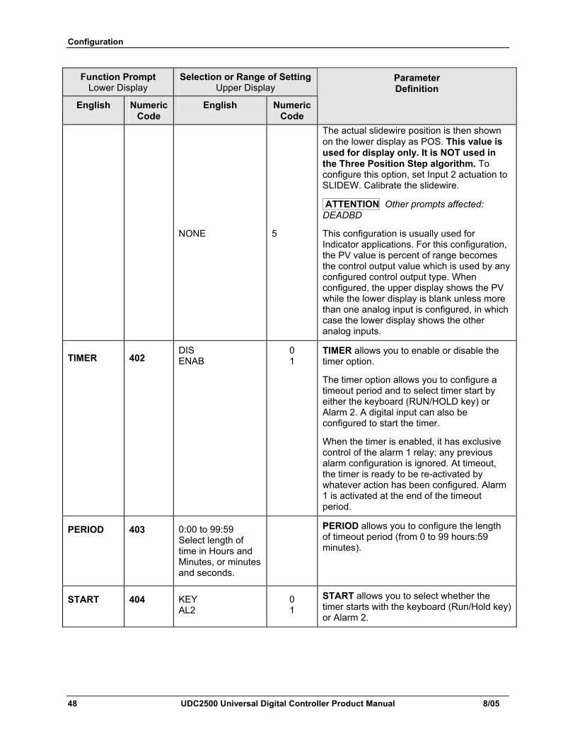
Configuration
48 UDC2500 Universal Digital Controller Product Manual 8/05
Function Prompt Lower Display
Selection or Range of Setting Upper Display
English Numeric Code
English Numeric Code
Parameter Definition
The actual slidewire position is then shown on the lower display as POS. This value is used for display only. It is NOT used in the Three Position Step algorithm. To configure this option, set Input 2 actuation to SLIDEW. Calibrate the slidewire.
ATTENTION Other prompts affected: DEADBD
NONE 5 This configuration is usually used for Indicator applications. For this configuration, the PV value is percent of range becomes the control output value which is used by any configured control output type. When configured, the upper display shows the PV while the lower display is blank unless more than one analog input is configured, in which case the lower display shows the other analog inputs.
TIMER 402 DIS ENAB
0 1
TIMER allows you to enable or disable the timer option.
The timer option allows you to configure a timeout period and to select timer start by either the keyboard (RUN/HOLD key) or Alarm 2. A digital input can also be configured to start the timer.
When the timer is enabled, it has exclusive control of the alarm 1 relay; any previous alarm configuration is ignored. At timeout, the timer is ready to be re-activated by whatever action has been configured. Alarm 1 is activated at the end of the timeout period.
PERIOD 403 0:00 to 99:59 Select length of time in Hours and Minutes, or minutes and seconds.
PERIOD allows you to configure the length of timeout period (from 0 to 99 hours:59 minutes).
START 404 KEY AL2
0 1
START allows you to select whether the timer starts with the keyboard (Run/Hold key) or Alarm 2.
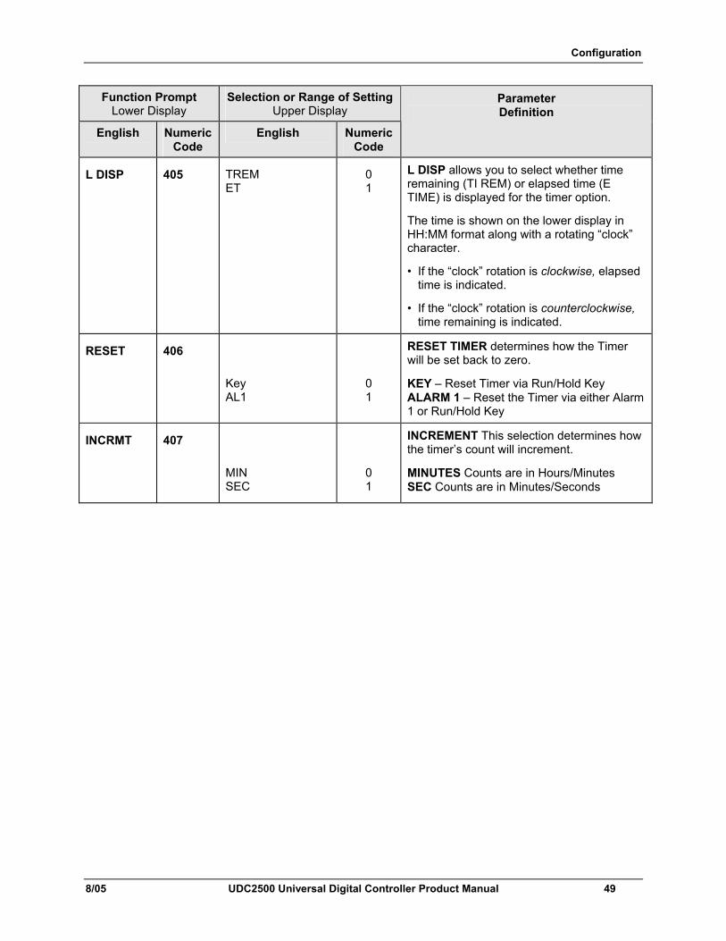
Configuration
8/05 UDC2500 Universal Digital Controller Product Manual 49
Function Prompt Lower Display
Selection or Range of Setting Upper Display
English Numeric Code
English Numeric Code
Parameter Definition
L DISP 405 TREM ET
0 1
L DISP allows you to select whether time remaining (TI REM) or elapsed time (E TIME) is displayed for the timer option.
The time is shown on the lower display in HH:MM format along with a rotating “clock” character.
• If the “clock” rotation is clockwise, elapsed time is indicated.
• If the “clock” rotation is counterclockwise, time remaining is indicated.
RESET 406
Key AL1
0 1
RESET TIMER determines how the Timer will be set back to zero.
KEY – Reset Timer via Run/Hold Key ALARM 1 – Reset the Timer via either Alarm 1 or Run/Hold Key
INCRMT 407
MIN SEC
0 1
INCREMENT This selection determines how the timer’s count will increment.
MINUTES Counts are in Hours/Minutes SEC Counts are in Minutes/Seconds
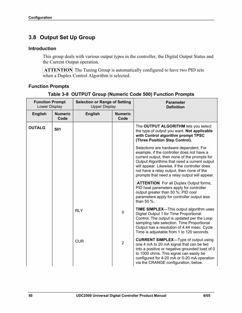
Configuration
50 UDC2500 Universal Digital Controller Product Manual 8/05
3.8 Output Set Up Group
Introduction This group deals with various output types in the controller, the Digital Output Status and the Current Output operation.
ATTENTION The Tuning Group is automatically configured to have two PID sets when a Duplex Control Algorithm is selected.
Function Prompts Table 3-8 OUTPUT Group (Numeric Code 500) Function Prompts
Function Prompt Lower Display
Selection or Range of Setting Upper Display
English Numeric Code
English Numeric Code
Parameter Definition
OUTALG 501 The OUTPUT ALGORITHM lets you select the type of output you want. Not applicable with Control algorithm prompt TPSC (Three Position Step Control).
Selections are hardware dependent. For example, if the controller does not have a current output, then none of the prompts for Output Algorithms that need a current output will appear. Likewise, if the controller does not have a relay output, then none of the prompts that need a relay output will appear.
ATTENTION For all Duplex Output forms, PID heat parameters apply for controller output greater than 50 %; PID cool parameters apply for controller output less than 50 %.
RLY 0 TIME SIMPLEX—This output algorithm uses Digital Output 1 for Time Proportional Control. The output is updated per the Loop sampling rate selection. Time Proportional Output has a resolution of 4.44 msec. Cycle Time is adjustable from 1 to 120 seconds.
CUR 2 CURRENT SIMPLEX—Type of output using one 4 mA to 20 mA signal that can be fed into a positive or negative grounded load of 0 to 1000 ohms. This signal can easily be configured for 4-20 mA or 0-20 mA operation via the CRANGE configuration, below.
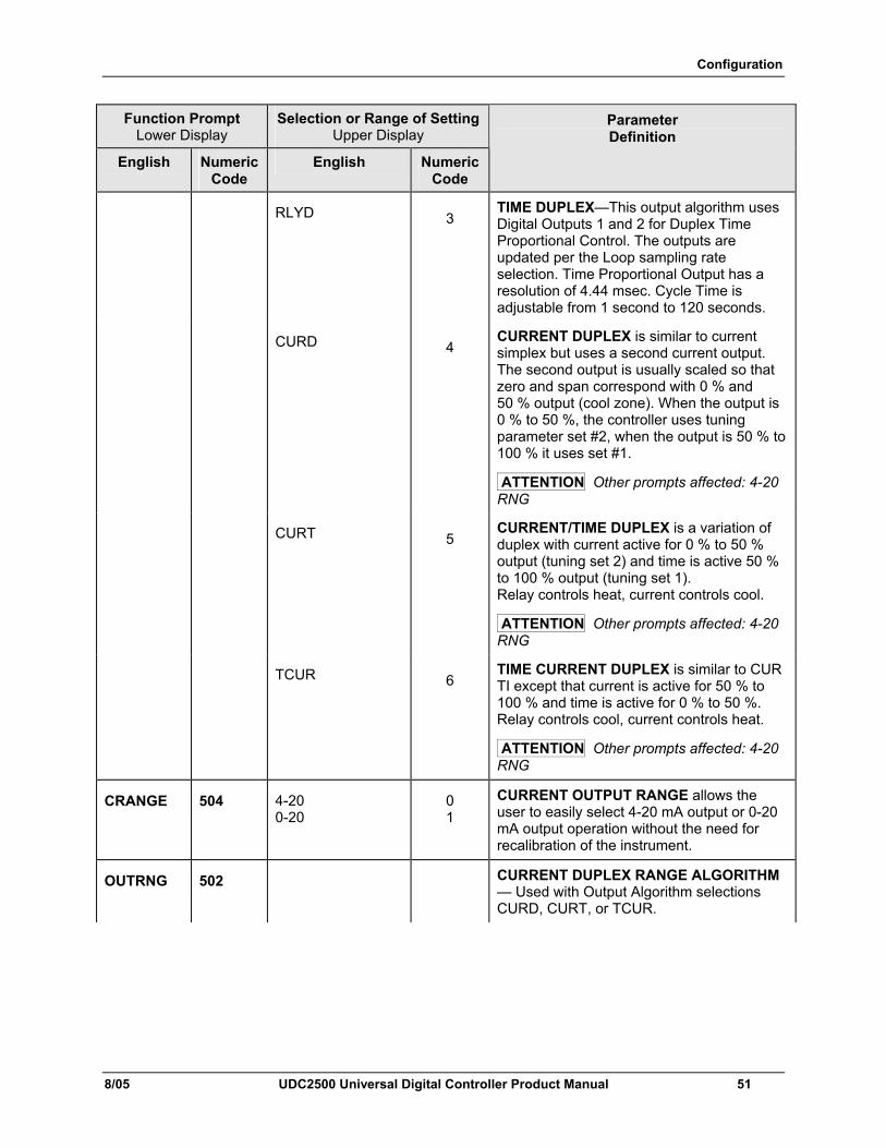
Configuration
8/05 UDC2500 Universal Digital Controller Product Manual 51
Function Prompt Lower Display
Selection or Range of Setting Upper Display
English Numeric Code
English Numeric Code
Parameter Definition
RLYD 3 TIME DUPLEX—This output algorithm uses Digital Outputs 1 and 2 for Duplex Time Proportional Control. The outputs are updated per the Loop sampling rate selection. Time Proportional Output has a resolution of 4.44 msec. Cycle Time is adjustable from 1 second to 120 seconds.
CURD 4 CURRENT DUPLEX is similar to current simplex but uses a second current output. The second output is usually scaled so that zero and span correspond with 0 % and 50 % output (cool zone). When the output is 0 % to 50 %, the controller uses tuning parameter set #2, when the output is 50 % to 100 % it uses set #1.
ATTENTION Other prompts affected: 4-20 RNG
CURT 5 CURRENT/TIME DUPLEX is a variation of duplex with current active for 0 % to 50 % output (tuning set 2) and time is active 50 % to 100 % output (tuning set 1). Relay controls heat, current controls cool.
ATTENTION Other prompts affected: 4-20 RNG
TCUR 6 TIME CURRENT DUPLEX is similar to CUR TI except that current is active for 50 % to 100 % and time is active for 0 % to 50 %. Relay controls cool, current controls heat.
ATTENTION Other prompts affected: 4-20 RNG
CRANGE 504 4-20 0-20
0 1
CURRENT OUTPUT RANGE allows the user to easily select 4-20 mA output or 0-20 mA output operation without the need for recalibration of the instrument.
OUTRNG 502 CURRENT DUPLEX RANGE ALGORITHM — Used with Output Algorithm selections CURD, CURT, or TCUR.
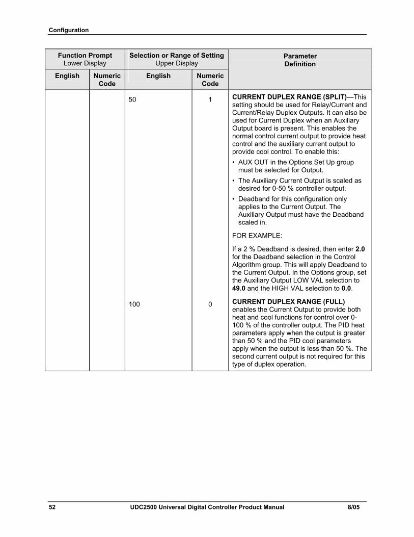
Configuration
52 UDC2500 Universal Digital Controller Product Manual 8/05
Function Prompt Lower Display
Selection or Range of Setting Upper Display
English Numeric Code
English Numeric Code
Parameter Definition
50 1 CURRENT DUPLEX RANGE (SPLIT)—This setting should be used for Relay/Current and Current/Relay Duplex Outputs. It can also be used for Current Duplex when an Auxiliary Output board is present. This enables the normal control current output to provide heat control and the auxiliary current output to provide cool control. To enable this: • AUX OUT in the Options Set Up group
must be selected for Output. • The Auxiliary Current Output is scaled as
desired for 0-50 % controller output. • Deadband for this configuration only
applies to the Current Output. The Auxiliary Output must have the Deadband scaled in.
FOR EXAMPLE:
If a 2 % Deadband is desired, then enter 2.0 for the Deadband selection in the Control Algorithm group. This will apply Deadband to the Current Output. In the Options group, set the Auxiliary Output LOW VAL selection to 49.0 and the HIGH VAL selection to 0.0.
100 0 CURRENT DUPLEX RANGE (FULL) enables the Current Output to provide both heat and cool functions for control over 0-100 % of the controller output. The PID heat parameters apply when the output is greater than 50 % and the PID cool parameters apply when the output is less than 50 %. The second current output is not required for this type of duplex operation.
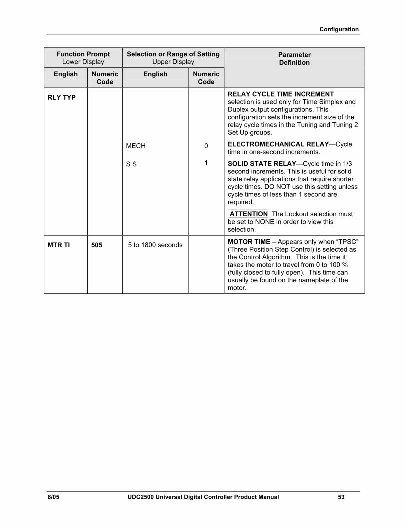
Configuration
8/05 UDC2500 Universal Digital Controller Product Manual 53
Function Prompt Lower Display
Selection or Range of Setting Upper Display
English Numeric Code
English Numeric Code
Parameter Definition
RLY TYP
MECH
S S
0
1
RELAY CYCLE TIME INCREMENT selection is used only for Time Simplex and Duplex output configurations. This configuration sets the increment size of the relay cycle times in the Tuning and Tuning 2 Set Up groups.
ELECTROMECHANICAL RELAY—Cycle time in one-second increments.
SOLID STATE RELAY—Cycle time in 1/3 second increments. This is useful for solid state relay applications that require shorter cycle times. DO NOT use this setting unless cycle times of less than 1 second are required.
ATTENTION The Lockout selection must be set to NONE in order to view this selection.
MTR TI 505 5 to 1800 seconds MOTOR TIME – Appears only when “TPSC” (Three Position Step Control) is selected as the Control Algorithm. This is the time it takes the motor to travel from 0 to 100 % (fully closed to fully open). This time can usually be found on the nameplate of the motor.
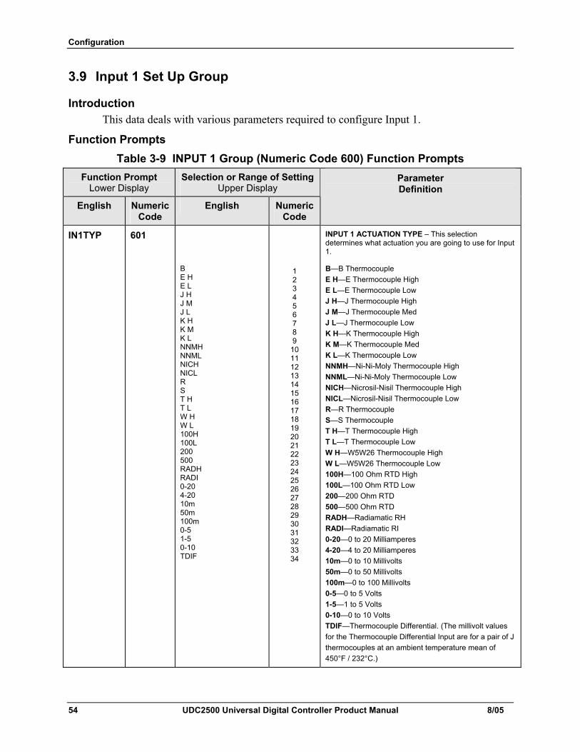
Configuration
54 UDC2500 Universal Digital Controller Product Manual 8/05
3.9 Input 1 Set Up Group
Introduction This data deals with various parameters required to configure Input 1.
Function Prompts Table 3-9 INPUT 1 Group (Numeric Code 600) Function Prompts
Function Prompt Lower Display
Selection or Range of Setting Upper Display
English Numeric Code
English Numeric Code
Parameter Definition
IN1TYP 601
B E H E L J H J M J L K H K M K L NNMH NNML NICH NICL R S T H T L W H W L 100H 100L 200 500 RADH RADI 0-20 4-20 10m 50m 100m 0-5 1-5 0-10 TDIF
1 2 3 4 5 6 7 8 9
10 11 12 13 14 15 16 17 18 19 20 21 22 23 24 25 26 27 28 29 30 31 32 33 34
INPUT 1 ACTUATION TYPE – This selection determines what actuation you are going to use for Input 1.
B—B Thermocouple E H—E Thermocouple High E L—E Thermocouple Low J H—J Thermocouple High J M—J Thermocouple Med J L—J Thermocouple Low K H—K Thermocouple High K M—K Thermocouple Med K L—K Thermocouple Low NNMH—Ni-Ni-Moly Thermocouple High NNML—Ni-Ni-Moly Thermocouple Low NICH—Nicrosil-Nisil Thermocouple High NICL—Nicrosil-Nisil Thermocouple Low R—R Thermocouple S—S Thermocouple T H—T Thermocouple High T L—T Thermocouple Low W H—W5W26 Thermocouple High W L—W5W26 Thermocouple Low 100H—100 Ohm RTD High 100L—100 Ohm RTD Low 200—200 Ohm RTD 500—500 Ohm RTD RADH—Radiamatic RH RADI—Radiamatic RI 0-20—0 to 20 Milliamperes 4-20—4 to 20 Milliamperes 10m—0 to 10 Millivolts 50m—0 to 50 Millivolts 100m—0 to 100 Millivolts 0-5—0 to 5 Volts 1-5—1 to 5 Volts 0-10—0 to 10 Volts TDIF—Thermocouple Differential. (The millivolt values for the Thermocouple Differential Input are for a pair of J thermocouples at an ambient temperature mean of 450°F / 232°C.)
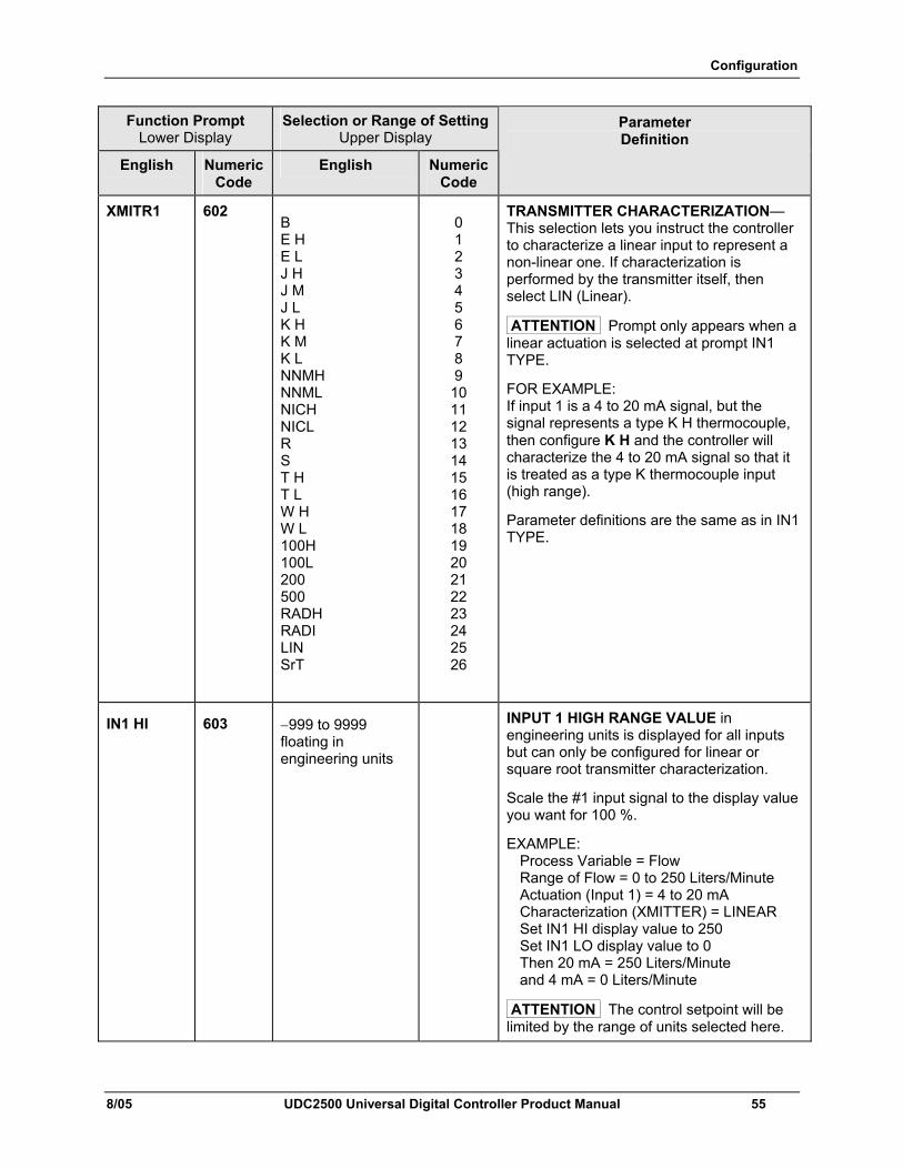
Configuration
8/05 UDC2500 Universal Digital Controller Product Manual 55
Function Prompt Lower Display
Selection or Range of Setting Upper Display
English Numeric Code
English Numeric Code
Parameter Definition
XMITR1 602 B E H E L J H J M J L K H K M K L NNMH NNML NICH NICL R S T H T L W H W L 100H 100L 200 500 RADH RADI LIN SrT
0 1 2 3 4 5 6 7 8 9 10 11 12 13 14 15 16 17 18 19 20 21 22 23 24 25 26
TRANSMITTER CHARACTERIZATION—This selection lets you instruct the controller to characterize a linear input to represent a non-linear one. If characterization is performed by the transmitter itself, then select LIN (Linear).
ATTENTION Prompt only appears when a linear actuation is selected at prompt IN1 TYPE.
FOR EXAMPLE: If input 1 is a 4 to 20 mA signal, but the signal represents a type K H thermocouple, then configure K H and the controller will characterize the 4 to 20 mA signal so that it is treated as a type K thermocouple input (high range).
Parameter definitions are the same as in IN1 TYPE.
IN1 HI 603 −999 to 9999 floating in engineering units
INPUT 1 HIGH RANGE VALUE in engineering units is displayed for all inputs but can only be configured for linear or square root transmitter characterization.
Scale the #1 input signal to the display value you want for 100 %.
EXAMPLE: Process Variable = Flow Range of Flow = 0 to 250 Liters/Minute Actuation (Input 1) = 4 to 20 mA Characterization (XMITTER) = LINEAR Set IN1 HI display value to 250 Set IN1 LO display value to 0 Then 20 mA = 250 Liters/Minute and 4 mA = 0 Liters/Minute
ATTENTION The control setpoint will be limited by the range of units selected here.
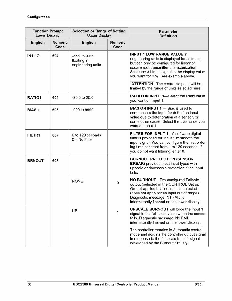
Configuration
56 UDC2500 Universal Digital Controller Product Manual 8/05
Function Prompt Lower Display
Selection or Range of Setting Upper Display
English Numeric Code
English Numeric Code
Parameter Definition
IN1 LO 604 −999 to 9999 floating in engineering units
INPUT 1 LOW RANGE VALUE in engineering units is displayed for all inputs but can only be configured for linear or square root transmitter characterization. Scale the #1 input signal to the display value you want for 0 %. See example above.
ATTENTION The control setpoint will be limited by the range of units selected here.
RATIO1 605 -20.0 to 20.0 RATIO ON INPUT 1—Select the Ratio value you want on Input 1.
BIAS 1 606 -999 to 9999 BIAS ON INPUT 1 — Bias is used to compensate the input for drift of an input value due to deterioration of a sensor, or some other cause. Select the bias value you want on Input 1.
FILTR1 607 0 to 120 seconds 0 = No Filter
FILTER FOR INPUT 1—A software digital filter is provided for Input 1 to smooth the input signal. You can configure the first order lag time constant from 1 to 120 seconds. If you do not want filtering, enter 0.
BRNOUT 608 BURNOUT PROTECTION (SENSOR BREAK) provides most input types with upscale or downscale protection if the input fails.
NONE 0 NO BURNOUT—Pre-configured Failsafe output (selected in the CONTROL Set up Group) applied if failed input is detected (does not apply for an input out of range). Diagnostic message IN1 FAIL is intermittently flashed on the lower display.
UP 1 UPSCALE BURNOUT will force the Input 1 signal to the full scale value when the sensor fails. Diagnostic message IN1 FAIL intermittently flashed on the lower display.
The controller remains in Automatic control mode and adjusts the controller output signal in response to the full scale Input 1 signal developed by the Burnout circuitry.
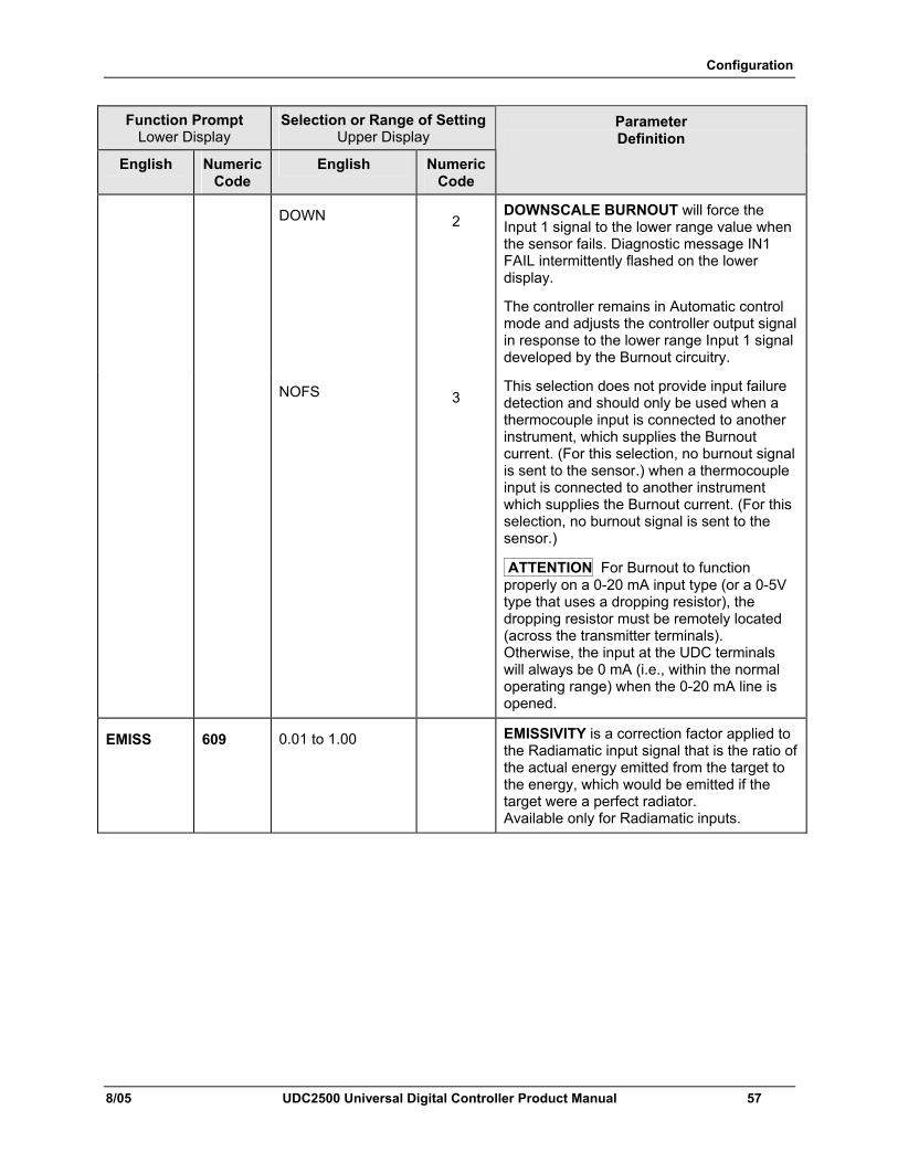
Configuration
8/05 UDC2500 Universal Digital Controller Product Manual 57
Function Prompt Lower Display
Selection or Range of Setting Upper Display
English Numeric Code
English Numeric Code
Parameter Definition
DOWN 2 DOWNSCALE BURNOUT will force the Input 1 signal to the lower range value when the sensor fails. Diagnostic message IN1 FAIL intermittently flashed on the lower display.
The controller remains in Automatic control mode and adjusts the controller output signal in response to the lower range Input 1 signal developed by the Burnout circuitry.
NOFS 3 This selection does not provide input failure detection and should only be used when a thermocouple input is connected to another instrument, which supplies the Burnout current. (For this selection, no burnout signal is sent to the sensor.) when a thermocouple input is connected to another instrument which supplies the Burnout current. (For this selection, no burnout signal is sent to the sensor.)
ATTENTION For Burnout to function properly on a 0-20 mA input type (or a 0-5V type that uses a dropping resistor), the dropping resistor must be remotely located (across the transmitter terminals). Otherwise, the input at the UDC terminals will always be 0 mA (i.e., within the normal operating range) when the 0-20 mA line is opened.
EMISS 609 0.01 to 1.00 EMISSIVITY is a correction factor applied to the Radiamatic input signal that is the ratio of the actual energy emitted from the target to the energy, which would be emitted if the target were a perfect radiator. Available only for Radiamatic inputs.
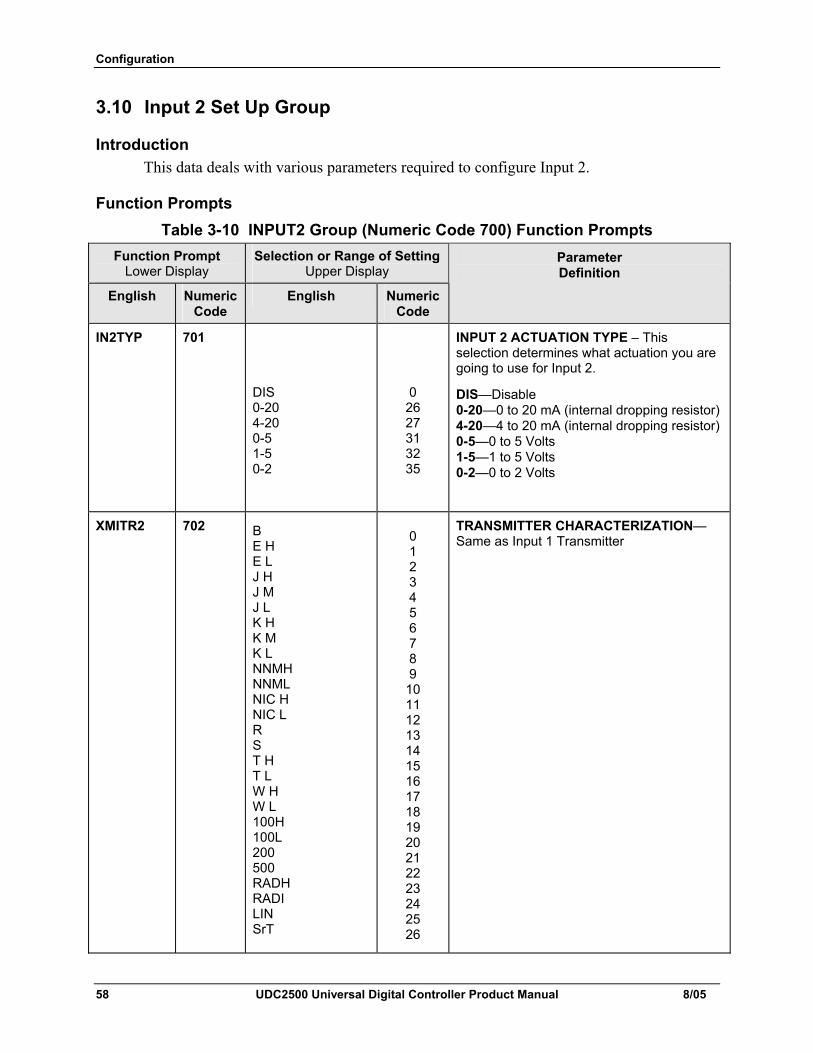
Configuration
58 UDC2500 Universal Digital Controller Product Manual 8/05
3.10 Input 2 Set Up Group
Introduction This data deals with various parameters required to configure Input 2.
Function Prompts Table 3-10 INPUT2 Group (Numeric Code 700) Function Prompts
Function Prompt Lower Display
Selection or Range of Setting Upper Display
English Numeric Code
English Numeric Code
Parameter Definition
IN2TYP 701
DIS 0-20 4-20 0-5 1-5 0-2
0 26 27 31 32 35
INPUT 2 ACTUATION TYPE – This selection determines what actuation you are going to use for Input 2.
DIS—Disable 0-20—0 to 20 mA (internal dropping resistor)4-20—4 to 20 mA (internal dropping resistor)0-5—0 to 5 Volts 1-5—1 to 5 Volts 0-2—0 to 2 Volts
XMITR2 702 B E H E L J H J M J L K H K M K L NNMH NNML NIC H NIC L R S T H T L W H W L 100H 100L 200 500 RADH RADI LIN SrT
0 1 2 3 4 5 6 7 8 9 10 11 12 13 14 15 16 17 18 19 20 21 22 23 24 25 26
TRANSMITTER CHARACTERIZATION—Same as Input 1 Transmitter
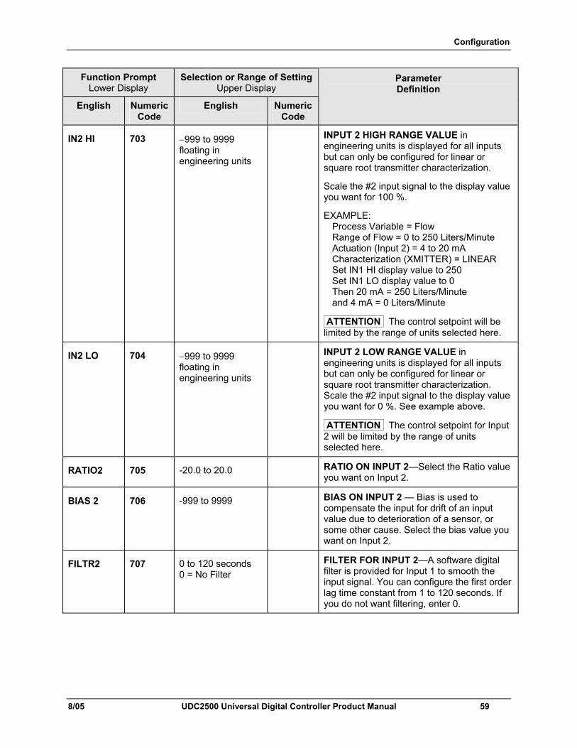
Configuration
8/05 UDC2500 Universal Digital Controller Product Manual 59
Function Prompt Lower Display
Selection or Range of Setting Upper Display
English Numeric Code
English Numeric Code
Parameter Definition
IN2 HI 703 −999 to 9999 floating in engineering units
INPUT 2 HIGH RANGE VALUE in engineering units is displayed for all inputs but can only be configured for linear or square root transmitter characterization.
Scale the #2 input signal to the display value you want for 100 %.
EXAMPLE: Process Variable = Flow Range of Flow = 0 to 250 Liters/Minute Actuation (Input 2) = 4 to 20 mA Characterization (XMITTER) = LINEAR Set IN1 HI display value to 250 Set IN1 LO display value to 0 Then 20 mA = 250 Liters/Minute and 4 mA = 0 Liters/Minute
ATTENTION The control setpoint will be limited by the range of units selected here.
IN2 LO 704 −999 to 9999 floating in engineering units
INPUT 2 LOW RANGE VALUE in engineering units is displayed for all inputs but can only be configured for linear or square root transmitter characterization. Scale the #2 input signal to the display value you want for 0 %. See example above.
ATTENTION The control setpoint for Input 2 will be limited by the range of units selected here.
RATIO2 705 -20.0 to 20.0 RATIO ON INPUT 2—Select the Ratio value you want on Input 2.
BIAS 2 706 -999 to 9999 BIAS ON INPUT 2 — Bias is used to compensate the input for drift of an input value due to deterioration of a sensor, or some other cause. Select the bias value you want on Input 2.
FILTR2 707 0 to 120 seconds 0 = No Filter
FILTER FOR INPUT 2—A software digital filter is provided for Input 1 to smooth the input signal. You can configure the first order lag time constant from 1 to 120 seconds. If you do not want filtering, enter 0.
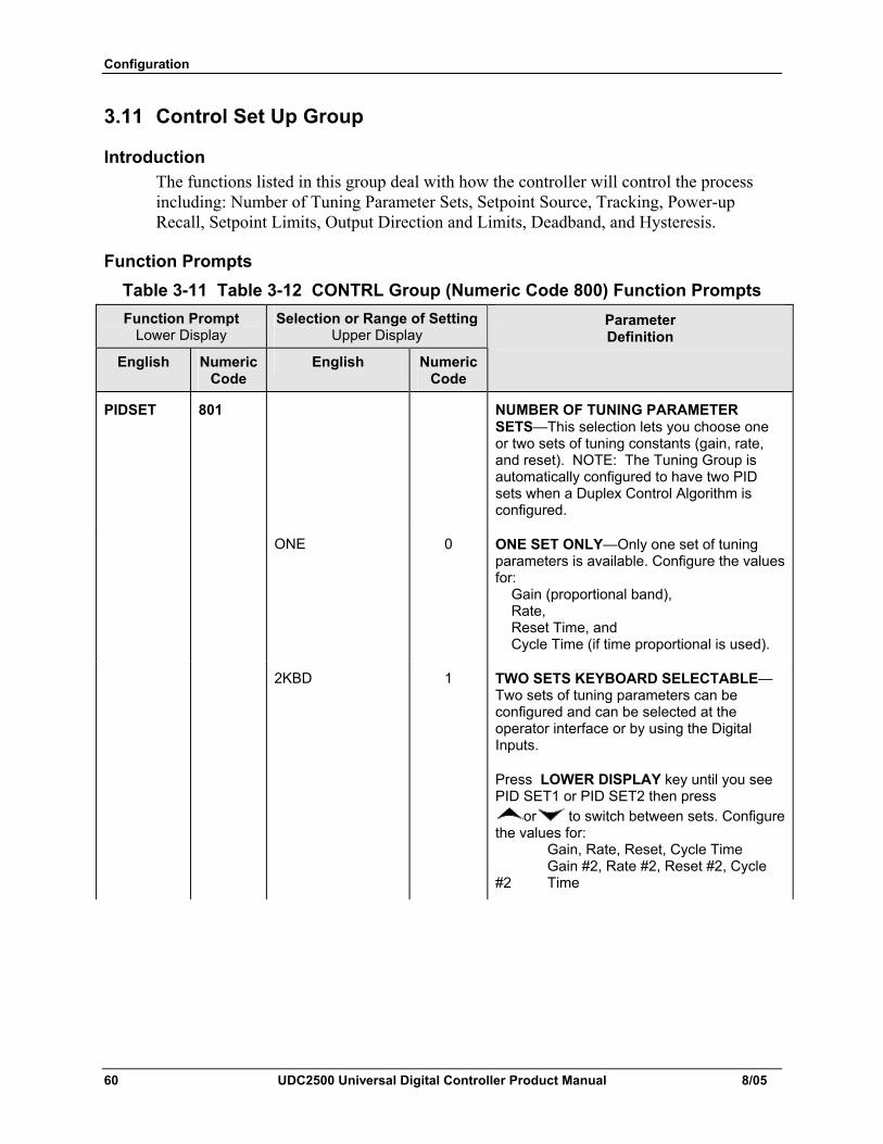
Configuration
60 UDC2500 Universal Digital Controller Product Manual 8/05
3.11 Control Set Up Group
Introduction The functions listed in this group deal with how the controller will control the process including: Number of Tuning Parameter Sets, Setpoint Source, Tracking, Power-up Recall, Setpoint Limits, Output Direction and Limits, Deadband, and Hysteresis.
Function Prompts Table 3-11 Table 3-12 CONTRL Group (Numeric Code 800) Function Prompts Function Prompt
Lower Display Selection or Range of Setting
Upper Display
English Numeric Code
English Numeric Code
Parameter Definition
PIDSET 801 NUMBER OF TUNING PARAMETER SETS—This selection lets you choose one or two sets of tuning constants (gain, rate, and reset). NOTE: The Tuning Group is automatically configured to have two PID sets when a Duplex Control Algorithm is configured.
ONE 0 ONE SET ONLY—Only one set of tuning parameters is available. Configure the values for: Gain (proportional band), Rate, Reset Time, and Cycle Time (if time proportional is used).
2KBD 1 TWO SETS KEYBOARD SELECTABLE—Two sets of tuning parameters can be configured and can be selected at the operator interface or by using the Digital Inputs.
Press LOWER DISPLAY key until you see PID SET1 or PID SET2 then press
or to switch between sets. Configure the values for: Gain, Rate, Reset, Cycle Time Gain #2, Rate #2, Reset #2, Cycle #2 Time
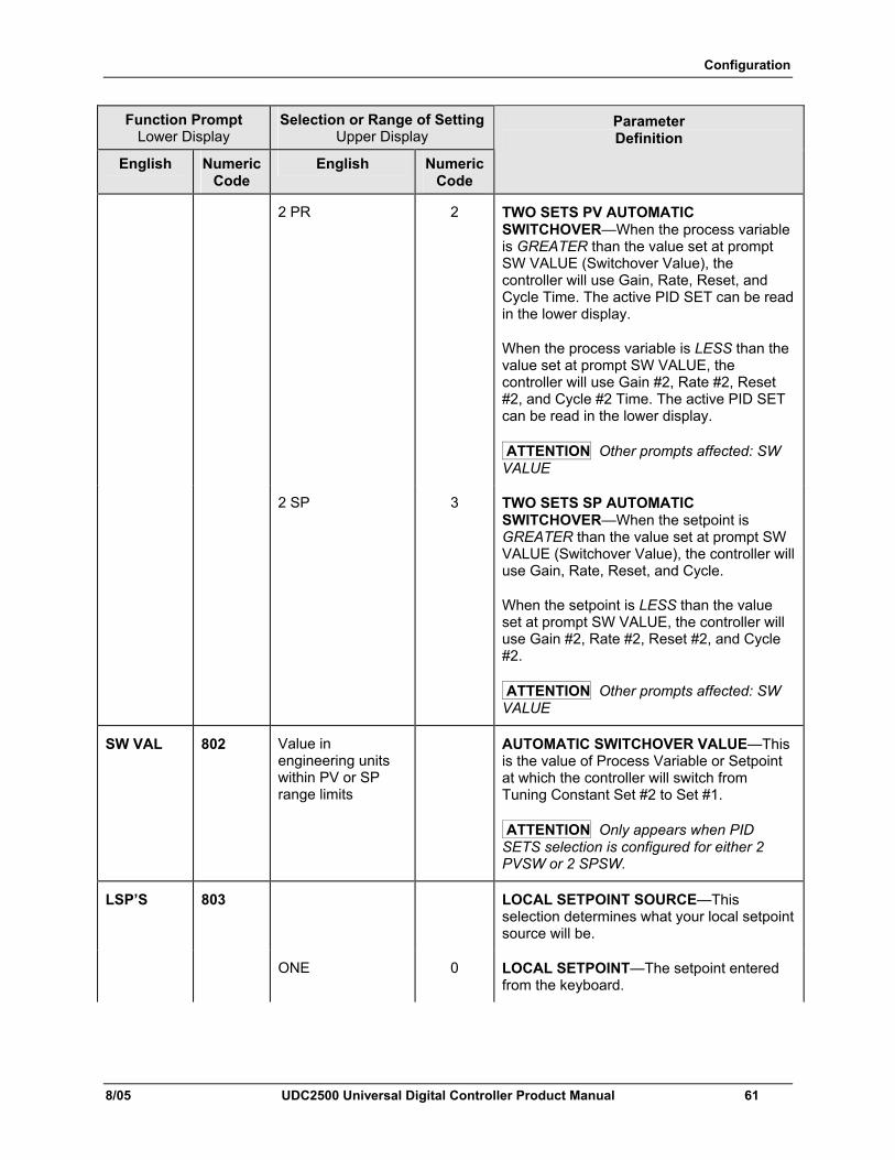
Configuration
8/05 UDC2500 Universal Digital Controller Product Manual 61
Function Prompt Lower Display
Selection or Range of Setting Upper Display
English Numeric Code
English Numeric Code
Parameter Definition
2 PR 2 TWO SETS PV AUTOMATIC SWITCHOVER—When the process variable is GREATER than the value set at prompt SW VALUE (Switchover Value), the controller will use Gain, Rate, Reset, and Cycle Time. The active PID SET can be read in the lower display.
When the process variable is LESS than the value set at prompt SW VALUE, the controller will use Gain #2, Rate #2, Reset #2, and Cycle #2 Time. The active PID SET can be read in the lower display.
ATTENTION Other prompts affected: SW VALUE
2 SP 3 TWO SETS SP AUTOMATIC SWITCHOVER—When the setpoint is GREATER than the value set at prompt SW VALUE (Switchover Value), the controller will use Gain, Rate, Reset, and Cycle.
When the setpoint is LESS than the value set at prompt SW VALUE, the controller will use Gain #2, Rate #2, Reset #2, and Cycle #2.
ATTENTION Other prompts affected: SW VALUE
SW VAL 802 Value in engineering units within PV or SP range limits
AUTOMATIC SWITCHOVER VALUE—This is the value of Process Variable or Setpoint at which the controller will switch from Tuning Constant Set #2 to Set #1.
ATTENTION Only appears when PID SETS selection is configured for either 2 PVSW or 2 SPSW.
LSP’S 803 LOCAL SETPOINT SOURCE—This selection determines what your local setpoint source will be.
ONE 0 LOCAL SETPOINT—The setpoint entered from the keyboard.
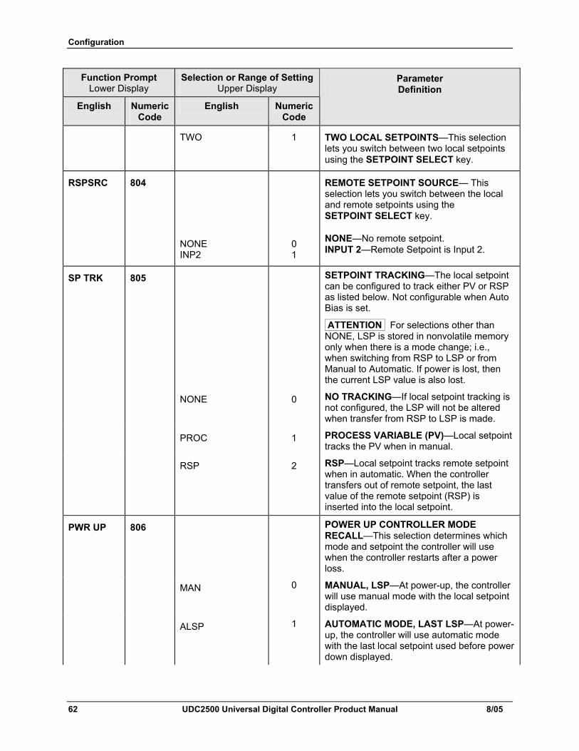
Configuration
62 UDC2500 Universal Digital Controller Product Manual 8/05
Function Prompt Lower Display
Selection or Range of Setting Upper Display
English Numeric Code
English Numeric Code
Parameter Definition
TWO 1 TWO LOCAL SETPOINTS—This selection lets you switch between two local setpoints using the SETPOINT SELECT key.
RSPSRC 804
NONE INP2
0 1
REMOTE SETPOINT SOURCE— This selection lets you switch between the local and remote setpoints using the SETPOINT SELECT key.
NONE—No remote setpoint. INPUT 2—Remote Setpoint is Input 2.
SP TRK 805 SETPOINT TRACKING—The local setpoint can be configured to track either PV or RSP as listed below. Not configurable when Auto Bias is set.
ATTENTION For selections other than NONE, LSP is stored in nonvolatile memory only when there is a mode change; i.e., when switching from RSP to LSP or from Manual to Automatic. If power is lost, then the current LSP value is also lost.
NONE 0 NO TRACKING—If local setpoint tracking is not configured, the LSP will not be altered when transfer from RSP to LSP is made.
PROC 1 PROCESS VARIABLE (PV)—Local setpoint tracks the PV when in manual.
RSP 2 RSP—Local setpoint tracks remote setpoint when in automatic. When the controller transfers out of remote setpoint, the last value of the remote setpoint (RSP) is inserted into the local setpoint.
PWR UP 806 POWER UP CONTROLLER MODE RECALL—This selection determines which mode and setpoint the controller will use when the controller restarts after a power loss.
MAN 0 MANUAL, LSP—At power-up, the controller will use manual mode with the local setpoint displayed.
ALSP 1 AUTOMATIC MODE, LAST LSP—At power-up, the controller will use automatic mode with the last local setpoint used before power down displayed.
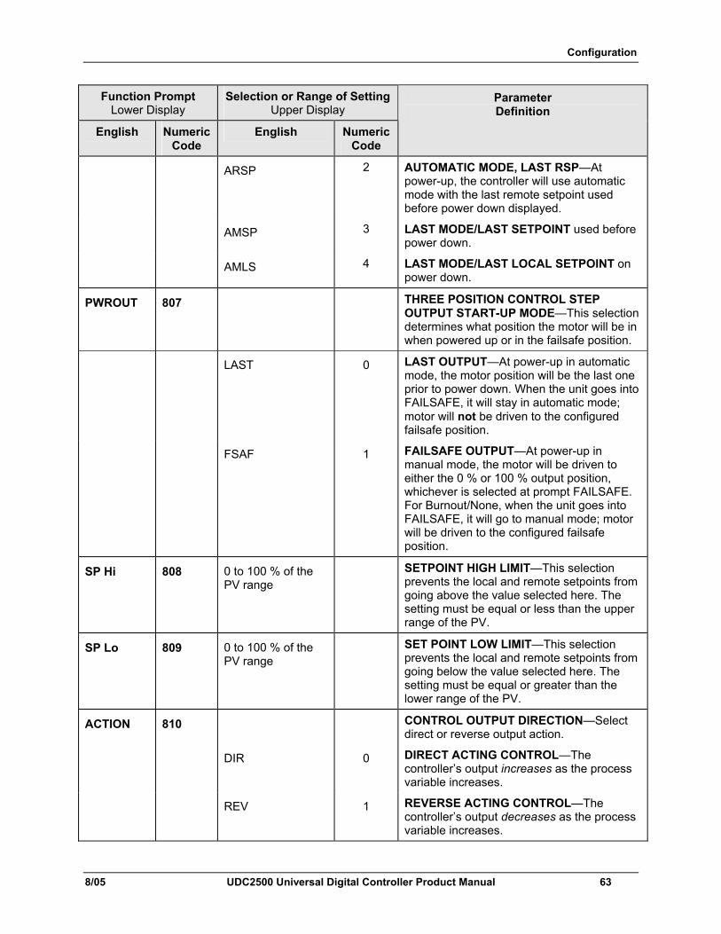
Configuration
8/05 UDC2500 Universal Digital Controller Product Manual 63
Function Prompt Lower Display
Selection or Range of Setting Upper Display
English Numeric Code
English Numeric Code
Parameter Definition
ARSP 2 AUTOMATIC MODE, LAST RSP—At power-up, the controller will use automatic mode with the last remote setpoint used before power down displayed.
AMSP 3 LAST MODE/LAST SETPOINT used before power down.
AMLS 4 LAST MODE/LAST LOCAL SETPOINT on power down.
PWROUT 807 THREE POSITION CONTROL STEP OUTPUT START-UP MODE—This selection determines what position the motor will be in when powered up or in the failsafe position.
LAST 0 LAST OUTPUT—At power-up in automatic mode, the motor position will be the last one prior to power down. When the unit goes into FAILSAFE, it will stay in automatic mode; motor will not be driven to the configured failsafe position.
FSAF 1 FAILSAFE OUTPUT—At power-up in manual mode, the motor will be driven to either the 0 % or 100 % output position, whichever is selected at prompt FAILSAFE. For Burnout/None, when the unit goes into FAILSAFE, it will go to manual mode; motor will be driven to the configured failsafe position.
SP Hi 808 0 to 100 % of the PV range
SETPOINT HIGH LIMIT—This selection prevents the local and remote setpoints from going above the value selected here. The setting must be equal or less than the upper range of the PV.
SP Lo 809 0 to 100 % of the PV range
SET POINT LOW LIMIT—This selection prevents the local and remote setpoints from going below the value selected here. The setting must be equal or greater than the lower range of the PV.
ACTION 810 CONTROL OUTPUT DIRECTION—Select direct or reverse output action.
DIR 0 DIRECT ACTING CONTROL—The controller’s output increases as the process variable increases.
REV 1 REVERSE ACTING CONTROL—The controller’s output decreases as the process variable increases.
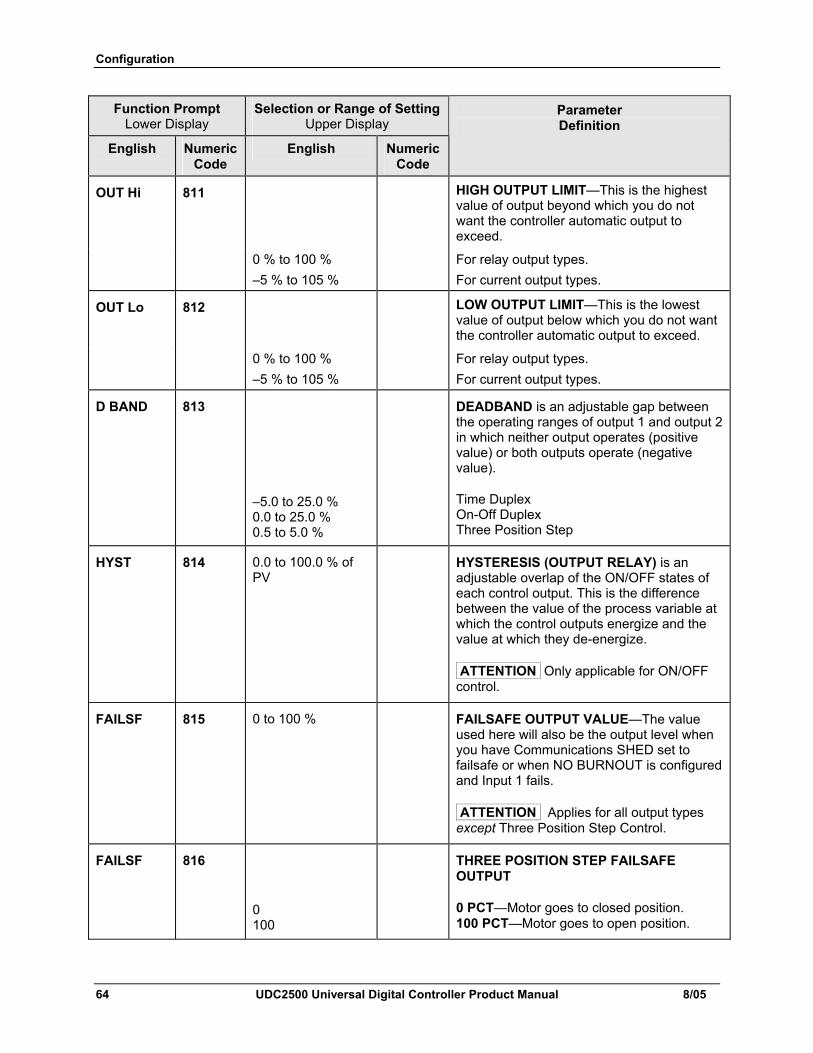
Configuration
64 UDC2500 Universal Digital Controller Product Manual 8/05
Function Prompt Lower Display
Selection or Range of Setting Upper Display
English Numeric Code
English Numeric Code
Parameter Definition
OUT Hi 811
HIGH OUTPUT LIMIT—This is the highest value of output beyond which you do not want the controller automatic output to exceed.
0 % to 100 % –5 % to 105 %
For relay output types. For current output types.
OUT Lo 812 LOW OUTPUT LIMIT—This is the lowest value of output below which you do not want the controller automatic output to exceed.
0 % to 100 % –5 % to 105 %
For relay output types. For current output types.
D BAND 813
–5.0 to 25.0 % 0.0 to 25.0 % 0.5 to 5.0 %
DEADBAND is an adjustable gap between the operating ranges of output 1 and output 2 in which neither output operates (positive value) or both outputs operate (negative value).
Time Duplex On-Off Duplex Three Position Step
HYST 814 0.0 to 100.0 % of PV
HYSTERESIS (OUTPUT RELAY) is an adjustable overlap of the ON/OFF states of each control output. This is the difference between the value of the process variable at which the control outputs energize and the value at which they de-energize.
ATTENTION Only applicable for ON/OFF control.
FAILSF 815 0 to 100 % FAILSAFE OUTPUT VALUE—The value used here will also be the output level when you have Communications SHED set to failsafe or when NO BURNOUT is configured and Input 1 fails.
ATTENTION Applies for all output types except Three Position Step Control.
FAILSF 816
0 100
THREE POSITION STEP FAILSAFE OUTPUT
0 PCT—Motor goes to closed position. 100 PCT—Motor goes to open position.
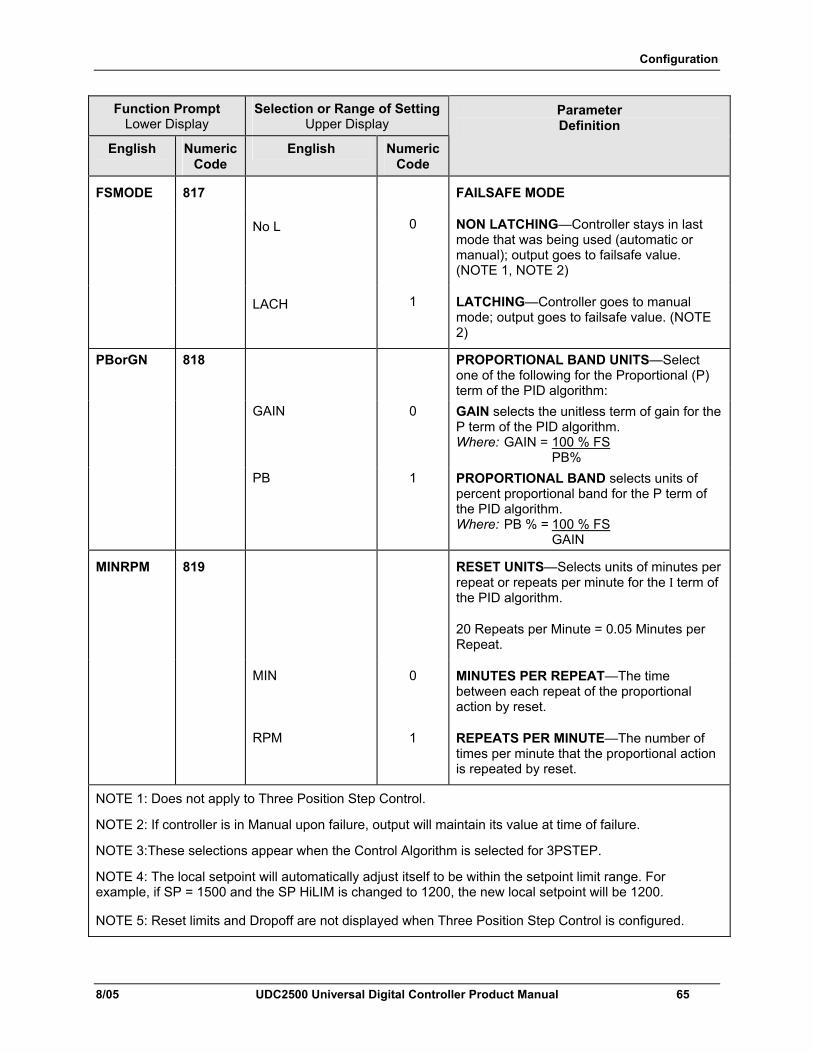
Configuration
8/05 UDC2500 Universal Digital Controller Product Manual 65
Function Prompt Lower Display
Selection or Range of Setting Upper Display
English Numeric Code
English Numeric Code
Parameter Definition
FSMODE 817 FAILSAFE MODE
No L 0 NON LATCHING—Controller stays in last mode that was being used (automatic or manual); output goes to failsafe value. (NOTE 1, NOTE 2)
LACH 1 LATCHING—Controller goes to manual mode; output goes to failsafe value. (NOTE 2)
PBorGN 818 PROPORTIONAL BAND UNITS—Select one of the following for the Proportional (P) term of the PID algorithm:
GAIN 0 GAIN selects the unitless term of gain for the P term of the PID algorithm. Where: GAIN = 100 % FS PB%
PB 1 PROPORTIONAL BAND selects units of percent proportional band for the P term of the PID algorithm. Where: PB % = 100 % FS GAIN
MINRPM 819 RESET UNITS—Selects units of minutes per repeat or repeats per minute for the I term of the PID algorithm.
20 Repeats per Minute = 0.05 Minutes per Repeat.
MIN 0 MINUTES PER REPEAT—The time between each repeat of the proportional action by reset.
RPM 1 REPEATS PER MINUTE—The number of times per minute that the proportional action is repeated by reset.
NOTE 1: Does not apply to Three Position Step Control.
NOTE 2: If controller is in Manual upon failure, output will maintain its value at time of failure.
NOTE 3:These selections appear when the Control Algorithm is selected for 3PSTEP.
NOTE 4: The local setpoint will automatically adjust itself to be within the setpoint limit range. For example, if SP = 1500 and the SP HiLIM is changed to 1200, the new local setpoint will be 1200.
NOTE 5: Reset limits and Dropoff are not displayed when Three Position Step Control is configured.
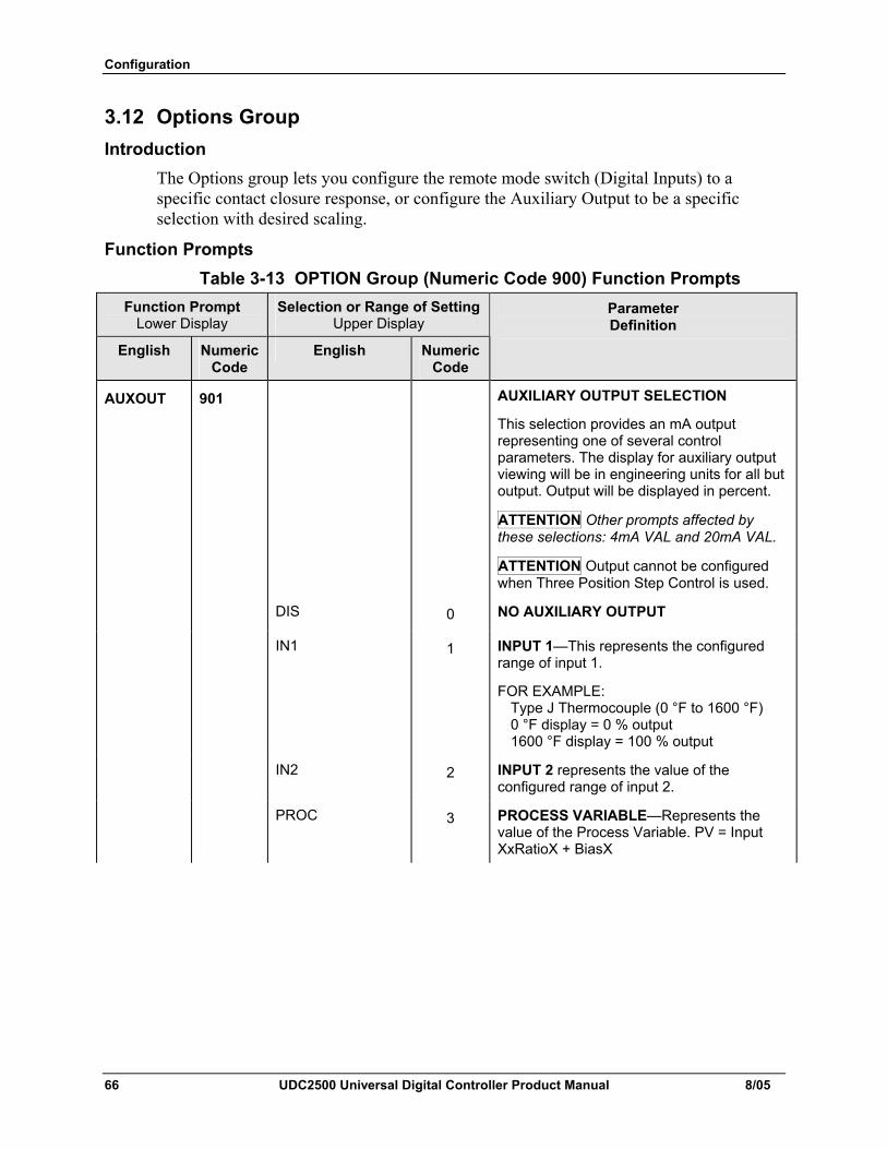
Configuration
66 UDC2500 Universal Digital Controller Product Manual 8/05
3.12 Options Group Introduction
The Options group lets you configure the remote mode switch (Digital Inputs) to a specific contact closure response, or configure the Auxiliary Output to be a specific selection with desired scaling.
Function Prompts Table 3-13 OPTION Group (Numeric Code 900) Function Prompts
Function Prompt Lower Display
Selection or Range of Setting Upper Display
English Numeric Code
English Numeric Code
Parameter Definition
AUXOUT 901 AUXILIARY OUTPUT SELECTION
This selection provides an mA output representing one of several control parameters. The display for auxiliary output viewing will be in engineering units for all but output. Output will be displayed in percent.
ATTENTION Other prompts affected by these selections: 4mA VAL and 20mA VAL.
ATTENTION Output cannot be configured when Three Position Step Control is used.
DIS 0 NO AUXILIARY OUTPUT
IN1 1 INPUT 1—This represents the configured range of input 1.
FOR EXAMPLE: Type J Thermocouple (0 °F to 1600 °F) 0 °F display = 0 % output 1600 °F display = 100 % output
IN2 2 INPUT 2 represents the value of the configured range of input 2.
PROC 3 PROCESS VARIABLE—Represents the value of the Process Variable. PV = Input XxRatioX + BiasX
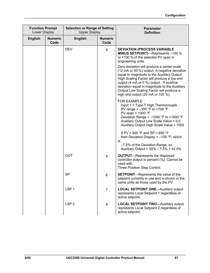
Configuration
8/05 UDC2500 Universal Digital Controller Product Manual 67
Function Prompt Lower Display
Selection or Range of Setting Upper Display
English Numeric Code
English Numeric Code
Parameter Definition
DEV 4 DEVIATION (PROCESS VARIABLE MINUS SETPOINT)—Represents –100 % to +100 % of the selected PV span in engineering units. Zero deviation will produce a center scale (12 mA or 50 %) output. A negative deviation equal in magnitude to the Auxiliary Output High Scaling Factor will produce a low end output (4 mA or 0 %) output. A positive deviation equal in magnitude to the Auxiliary Output Low Scaling Factor will produce a high end output (20 mA or 100 %).
FOR EXAMPLE: Input 1 = Type T High Thermocouple PV range = –300 °F to +700 °F PV span = 1000 °F Deviation Range = –1000 °F to +1000 °F Auxiliary Output Low Scale Value = 0.0 Auxiliary Output High Scale Value = 1000 If PV = 500 °F and SP = 650 °F then Deviation Display = –150 °F, which is –7.5% of the Deviation Range, so Auxiliary Output = 50% – 7.5% = 42.5%
OUT 5 OUTPUT—Represents the displayed controller output in percent (%). Cannot be used with Three Position Step Control.
SP 6 SETPOINT—Represents the value of the setpoint currently in use and is shown in the same units as those used by the PV.
LSP 1 7 LOCAL SETPOINT ONE—Auxiliary output represents Local Setpoint 1 regardless of active setpoint.
LSP 2 8 LOCAL SETPOINT TWO—Auxiliary output represents Local Setpoint 2 regardless of active setpoint.
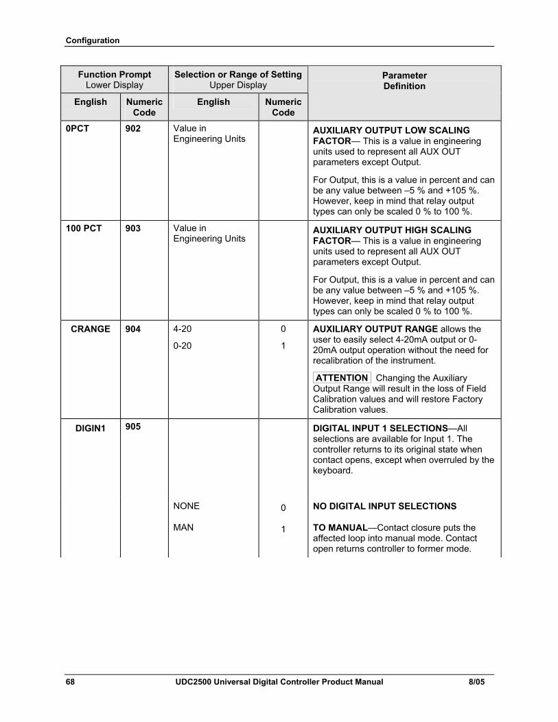
Configuration
68 UDC2500 Universal Digital Controller Product Manual 8/05
Function Prompt Lower Display
Selection or Range of Setting Upper Display
English Numeric Code
English Numeric Code
Parameter Definition
0PCT 902 Value in Engineering Units
AUXILIARY OUTPUT LOW SCALING FACTOR— This is a value in engineering units used to represent all AUX OUT parameters except Output.
For Output, this is a value in percent and can be any value between –5 % and +105 %. However, keep in mind that relay output types can only be scaled 0 % to 100 %.
100 PCT 903 Value in Engineering Units
AUXILIARY OUTPUT HIGH SCALING FACTOR— This is a value in engineering units used to represent all AUX OUT parameters except Output.
For Output, this is a value in percent and can be any value between –5 % and +105 %. However, keep in mind that relay output types can only be scaled 0 % to 100 %.
CRANGE 904 4-20
0-20
0
1
AUXILIARY OUTPUT RANGE allows the user to easily select 4-20mA output or 0-20mA output operation without the need for recalibration of the instrument.
ATTENTION Changing the Auxiliary Output Range will result in the loss of Field Calibration values and will restore Factory Calibration values.
DIGIN1 905 DIGITAL INPUT 1 SELECTIONS—All selections are available for Input 1. The controller returns to its original state when contact opens, except when overruled by the keyboard.
NONE 0 NO DIGITAL INPUT SELECTIONS
MAN 1 TO MANUAL—Contact closure puts the affected loop into manual mode. Contact open returns controller to former mode.
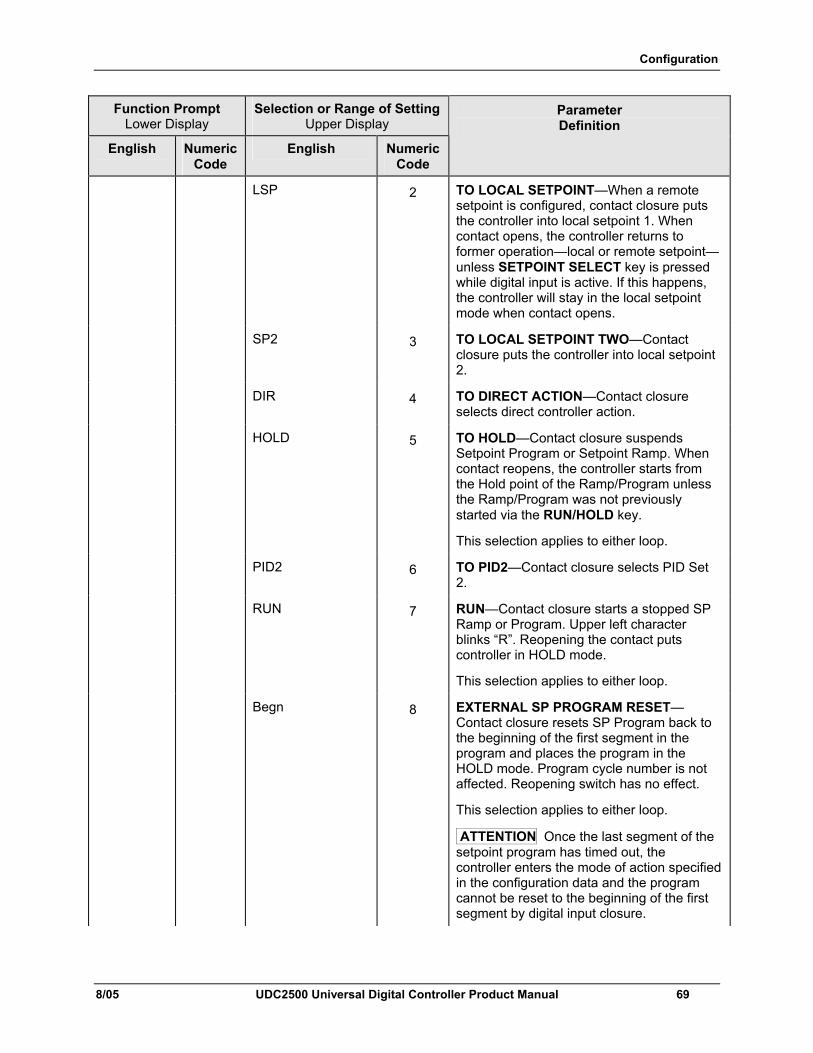
Configuration
8/05 UDC2500 Universal Digital Controller Product Manual 69
Function Prompt Lower Display
Selection or Range of Setting Upper Display
English Numeric Code
English Numeric Code
Parameter Definition
LSP 2 TO LOCAL SETPOINT—When a remote setpoint is configured, contact closure puts the controller into local setpoint 1. When contact opens, the controller returns to former operation—local or remote setpoint—unless SETPOINT SELECT key is pressed while digital input is active. If this happens, the controller will stay in the local setpoint mode when contact opens.
SP2 3 TO LOCAL SETPOINT TWO—Contact closure puts the controller into local setpoint 2.
DIR 4 TO DIRECT ACTION—Contact closure selects direct controller action.
HOLD 5 TO HOLD—Contact closure suspends Setpoint Program or Setpoint Ramp. When contact reopens, the controller starts from the Hold point of the Ramp/Program unless the Ramp/Program was not previously started via the RUN/HOLD key.
This selection applies to either loop.
PID2 6 TO PID2—Contact closure selects PID Set 2.
RUN 7 RUN—Contact closure starts a stopped SP Ramp or Program. Upper left character blinks “R”. Reopening the contact puts controller in HOLD mode.
This selection applies to either loop.
Begn 8 EXTERNAL SP PROGRAM RESET—Contact closure resets SP Program back to the beginning of the first segment in the program and places the program in the HOLD mode. Program cycle number is not affected. Reopening switch has no effect.
This selection applies to either loop.
ATTENTION Once the last segment of the setpoint program has timed out, the controller enters the mode of action specified in the configuration data and the program cannot be reset to the beginning of the first segment by digital input closure.
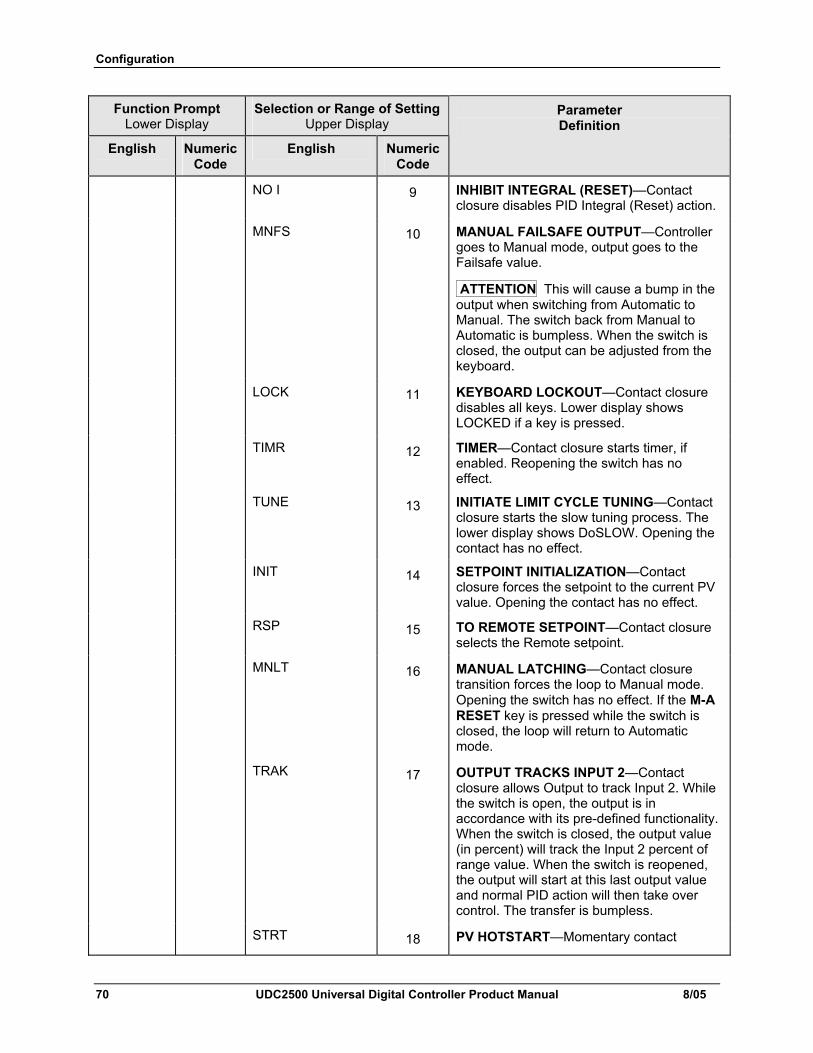
Configuration
70 UDC2500 Universal Digital Controller Product Manual 8/05
Function Prompt Lower Display
Selection or Range of Setting Upper Display
English Numeric Code
English Numeric Code
Parameter Definition
NO I 9 INHIBIT INTEGRAL (RESET)—Contact closure disables PID Integral (Reset) action.
MNFS 10 MANUAL FAILSAFE OUTPUT—Controller goes to Manual mode, output goes to the Failsafe value.
ATTENTION This will cause a bump in the output when switching from Automatic to Manual. The switch back from Manual to Automatic is bumpless. When the switch is closed, the output can be adjusted from the keyboard.
LOCK 11 KEYBOARD LOCKOUT—Contact closure disables all keys. Lower display shows LOCKED if a key is pressed.
TIMR 12 TIMER—Contact closure starts timer, if enabled. Reopening the switch has no effect.
TUNE 13 INITIATE LIMIT CYCLE TUNING—Contact closure starts the slow tuning process. The lower display shows DoSLOW. Opening the contact has no effect.
INIT 14 SETPOINT INITIALIZATION—Contact closure forces the setpoint to the current PV value. Opening the contact has no effect.
RSP 15 TO REMOTE SETPOINT—Contact closure selects the Remote setpoint.
MNLT 16 MANUAL LATCHING—Contact closure transition forces the loop to Manual mode. Opening the switch has no effect. If the M-A RESET key is pressed while the switch is closed, the loop will return to Automatic mode.
TRAK 17 OUTPUT TRACKS INPUT 2—Contact closure allows Output to track Input 2. While the switch is open, the output is in accordance with its pre-defined functionality. When the switch is closed, the output value (in percent) will track the Input 2 percent of range value. When the switch is reopened, the output will start at this last output value and normal PID action will then take over control. The transfer is bumpless.
STRT 18 PV HOTSTART—Momentary contact
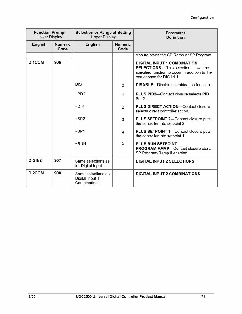
Configuration
8/05 UDC2500 Universal Digital Controller Product Manual 71
Function Prompt Lower Display
Selection or Range of Setting Upper Display
English Numeric Code
English Numeric Code
Parameter Definition
closure starts the SP Ramp or SP Program.
DI1COM 906 DIGITAL INPUT 1 COMBINATION SELECTIONS —This selection allows the specified function to occur in addition to the one chosen for DIG IN 1.
DIS 0 DISABLE—Disables combination function.
+PD2 1 PLUS PID2—Contact closure selects PID Set 2.
+DIR 2 PLUS DIRECT ACTION—Contact closure selects direct controller action.
+SP2 3 PLUS SETPOINT 2—Contact closure puts the controller into setpoint 2.
+SP1 4 PLUS SETPOINT 1—Contact closure puts the controller into setpoint 1.
+RUN 5 PLUS RUN SETPOINT PROGRAM/RAMP—Contact closure starts SP Program/Ramp if enabled.
DIGIN2 907 Same selections as for Digital Input 1
DIGITAL INPUT 2 SELECTIONS
DI2COM 908 Same selections as Digital Input 1 Combinations
DIGITAL INPUT 2 COMBINATIONS
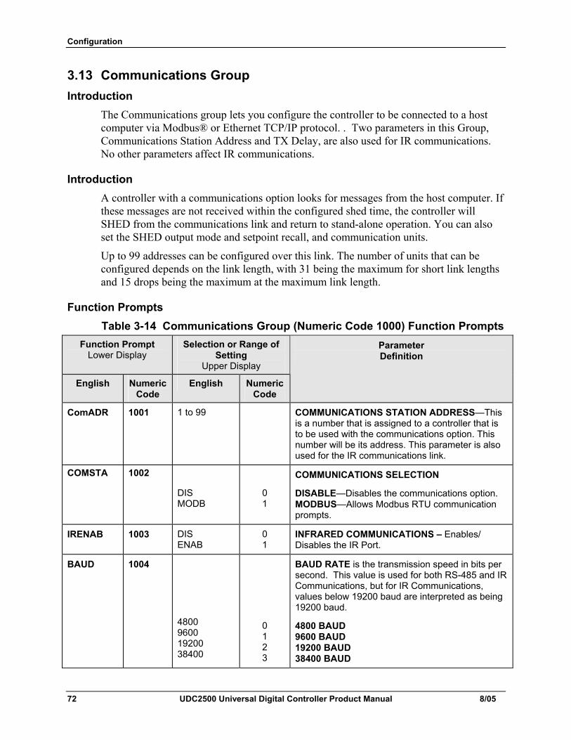
Configuration
72 UDC2500 Universal Digital Controller Product Manual 8/05
3.13 Communications Group Introduction
The Communications group lets you configure the controller to be connected to a host computer via Modbus® or Ethernet TCP/IP protocol. . Two parameters in this Group, Communications Station Address and TX Delay, are also used for IR communications. No other parameters affect IR communications.
Introduction A controller with a communications option looks for messages from the host computer. If these messages are not received within the configured shed time, the controller will SHED from the communications link and return to stand-alone operation. You can also set the SHED output mode and setpoint recall, and communication units.
Up to 99 addresses can be configured over this link. The number of units that can be configured depends on the link length, with 31 being the maximum for short link lengths and 15 drops being the maximum at the maximum link length.
Function Prompts Table 3-14 Communications Group (Numeric Code 1000) Function Prompts
Function Prompt Lower Display
Selection or Range of Setting
Upper Display
English Numeric Code
English Numeric Code
Parameter Definition
ComADR 1001 1 to 99 COMMUNICATIONS STATION ADDRESS—This is a number that is assigned to a controller that is to be used with the communications option. This number will be its address. This parameter is also used for the IR communications link.
COMSTA 1002
DIS MODB
0 1
COMMUNICATIONS SELECTION
DISABLE—Disables the communications option. MODBUS—Allows Modbus RTU communication prompts.
IRENAB 1003 DIS ENAB
0 1
INFRARED COMMUNICATIONS – Enables/ Disables the IR Port.
BAUD 1004 BAUD RATE is the transmission speed in bits per second. This value is used for both RS-485 and IR Communications, but for IR Communications, values below 19200 baud are interpreted as being 19200 baud.
4800 9600 19200 38400
0 1 2 3
4800 BAUD 9600 BAUD 19200 BAUD 38400 BAUD
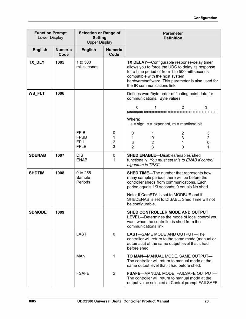
Configuration
8/05 UDC2500 Universal Digital Controller Product Manual 73
Function Prompt Lower Display
Selection or Range of Setting
Upper Display
English Numeric Code
English Numeric Code
Parameter Definition
TX_DLY 1005 1 to 500 milliseconds
TX DELAY—Configurable response-delay timer allows you to force the UDC to delay its response for a time period of from 1 to 500 milliseconds compatible with the host system hardware/software. This parameter is also used for the IR communications link.
WS_FLT 1006
FP B FPBB FP L FPLB
0 1 2 3
Defines word/byte order of floating point data for communications. Byte values: 0 1 2 3 seeeeeee emmmmmmm mmmmmmmm mmmmmmmm
Where: s = sign, e = exponent, m = mantissa bit 0 1 2 3 1 0 3 2 3 2 1 0 2 3 0 1
SDENAB 1007 DIS ENAB
0 1
SHED ENABLE—Disables/enables shed functionaliy. You must set this to ENAB if control algorithm is TPSC.
SHDTIM 1008 0 to 255 Sample Periods
SHED TIME—The number that represents how many sample periods there will be before the controller sheds from communications. Each period equals 1/3 seconds; 0 equals No shed.
Note: If ComSTA is set to MODBUS and if SHEDENAB is set to DISABL, Shed Time will not be configurable.
SDMODE 1009 SHED CONTROLLER MODE AND OUTPUT LEVEL—Determines the mode of local control you want when the controller is shed from the communications link.
LAST 0 LAST—SAME MODE AND OUTPUT—The controller will return to the same mode (manual or automatic) at the same output level that it had before shed.
MAN 1 TO MAN—MANUAL MODE, SAME OUTPUT—The controller will return to manual mode at the same output level that it had before shed.
FSAFE 2 FSAFE—MANUAL MODE, FAILSAFE OUTPUT—The controller will return to manual mode at the output value selected at Control prompt FAILSAFE.
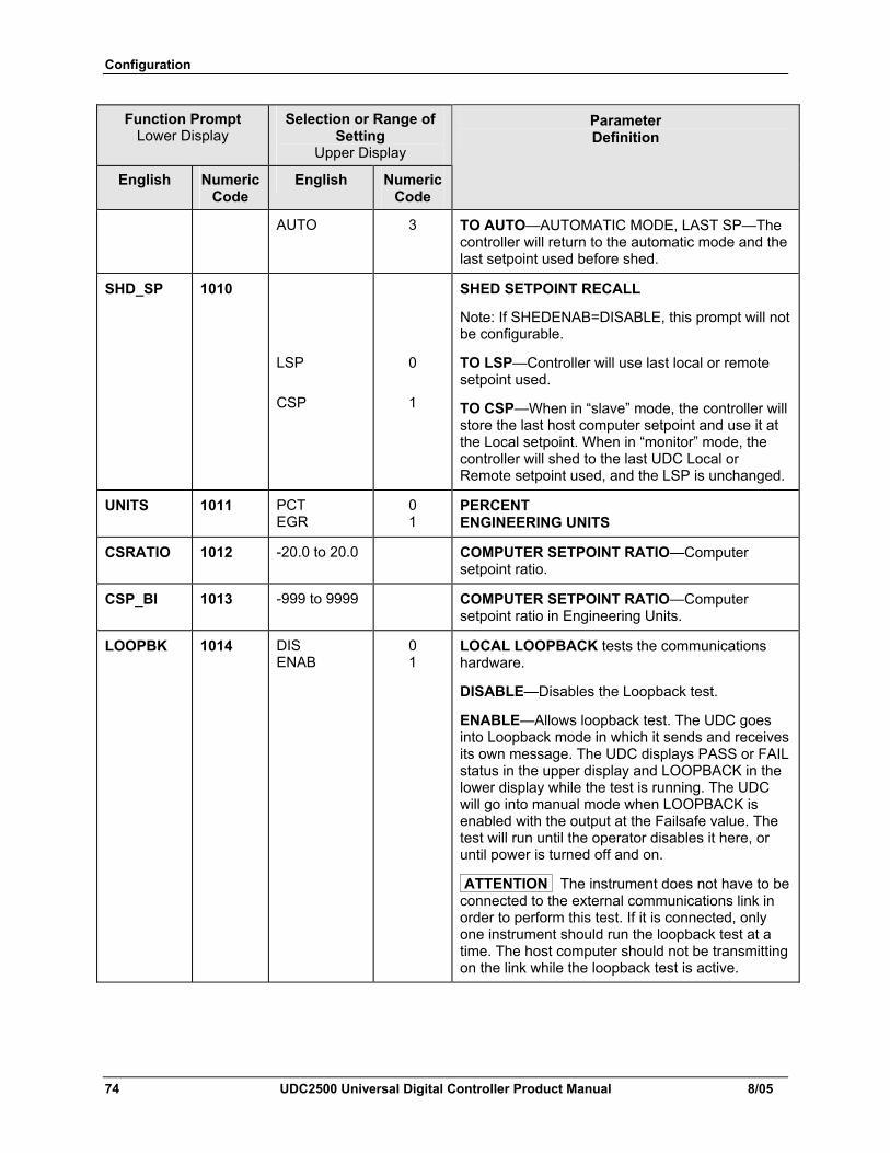
Configuration
74 UDC2500 Universal Digital Controller Product Manual 8/05
Function Prompt Lower Display
Selection or Range of Setting
Upper Display
English Numeric Code
English Numeric Code
Parameter Definition
AUTO 3 TO AUTO—AUTOMATIC MODE, LAST SP—The controller will return to the automatic mode and the last setpoint used before shed.
SHD_SP 1010
LSP
CSP
0
1
SHED SETPOINT RECALL
Note: If SHEDENAB=DISABLE, this prompt will not be configurable.
TO LSP—Controller will use last local or remote setpoint used.
TO CSP—When in “slave” mode, the controller will store the last host computer setpoint and use it at the Local setpoint. When in “monitor” mode, the controller will shed to the last UDC Local or Remote setpoint used, and the LSP is unchanged.
UNITS 1011 PCT EGR
0 1
PERCENT ENGINEERING UNITS
CSRATIO 1012 -20.0 to 20.0 COMPUTER SETPOINT RATIO—Computer setpoint ratio.
CSP_BI 1013 -999 to 9999 COMPUTER SETPOINT RATIO—Computer setpoint ratio in Engineering Units.
LOOPBK 1014 DIS ENAB
0 1
LOCAL LOOPBACK tests the communications hardware.
DISABLE—Disables the Loopback test.
ENABLE—Allows loopback test. The UDC goes into Loopback mode in which it sends and receives its own message. The UDC displays PASS or FAIL status in the upper display and LOOPBACK in the lower display while the test is running. The UDC will go into manual mode when LOOPBACK is enabled with the output at the Failsafe value. The test will run until the operator disables it here, or until power is turned off and on.
ATTENTION The instrument does not have to be connected to the external communications link in order to perform this test. If it is connected, only one instrument should run the loopback test at a time. The host computer should not be transmitting on the link while the loopback test is active.
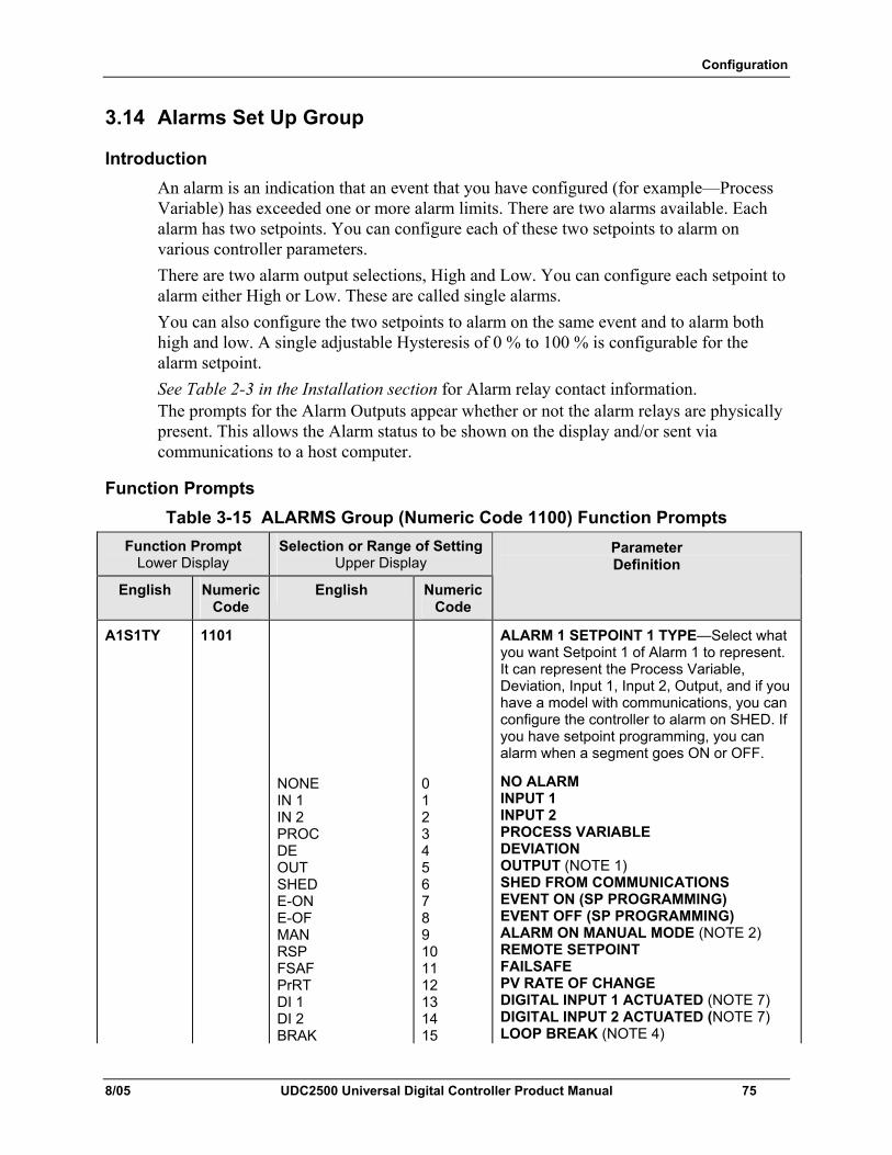
Configuration
8/05 UDC2500 Universal Digital Controller Product Manual 75
3.14 Alarms Set Up Group
Introduction An alarm is an indication that an event that you have configured (for example—Process Variable) has exceeded one or more alarm limits. There are two alarms available. Each alarm has two setpoints. You can configure each of these two setpoints to alarm on various controller parameters. There are two alarm output selections, High and Low. You can configure each setpoint to alarm either High or Low. These are called single alarms. You can also configure the two setpoints to alarm on the same event and to alarm both high and low. A single adjustable Hysteresis of 0 % to 100 % is configurable for the alarm setpoint. See Table 2-3 in the Installation section for Alarm relay contact information. The prompts for the Alarm Outputs appear whether or not the alarm relays are physically present. This allows the Alarm status to be shown on the display and/or sent via communications to a host computer.
Function Prompts Table 3-15 ALARMS Group (Numeric Code 1100) Function Prompts
Function Prompt Lower Display
Selection or Range of Setting Upper Display
English Numeric Code
English Numeric Code
Parameter Definition
A1S1TY 1101
NONE IN 1 IN 2 PROC DE OUT SHED E-ON E-OF MAN RSP FSAF PrRT DI 1 DI 2 BRAK
0 1 2 3 4 5 6 7 8 9 10 11 12 13 14 15
ALARM 1 SETPOINT 1 TYPE—Select what you want Setpoint 1 of Alarm 1 to represent. It can represent the Process Variable, Deviation, Input 1, Input 2, Output, and if you have a model with communications, you can configure the controller to alarm on SHED. If you have setpoint programming, you can alarm when a segment goes ON or OFF.
NO ALARM INPUT 1 INPUT 2 PROCESS VARIABLE DEVIATION OUTPUT (NOTE 1) SHED FROM COMMUNICATIONS EVENT ON (SP PROGRAMMING) EVENT OFF (SP PROGRAMMING) ALARM ON MANUAL MODE (NOTE 2) REMOTE SETPOINT FAILSAFE PV RATE OF CHANGE DIGITAL INPUT 1 ACTUATED (NOTE 7) DIGITAL INPUT 2 ACTUATED (NOTE 7) LOOP BREAK (NOTE 4)
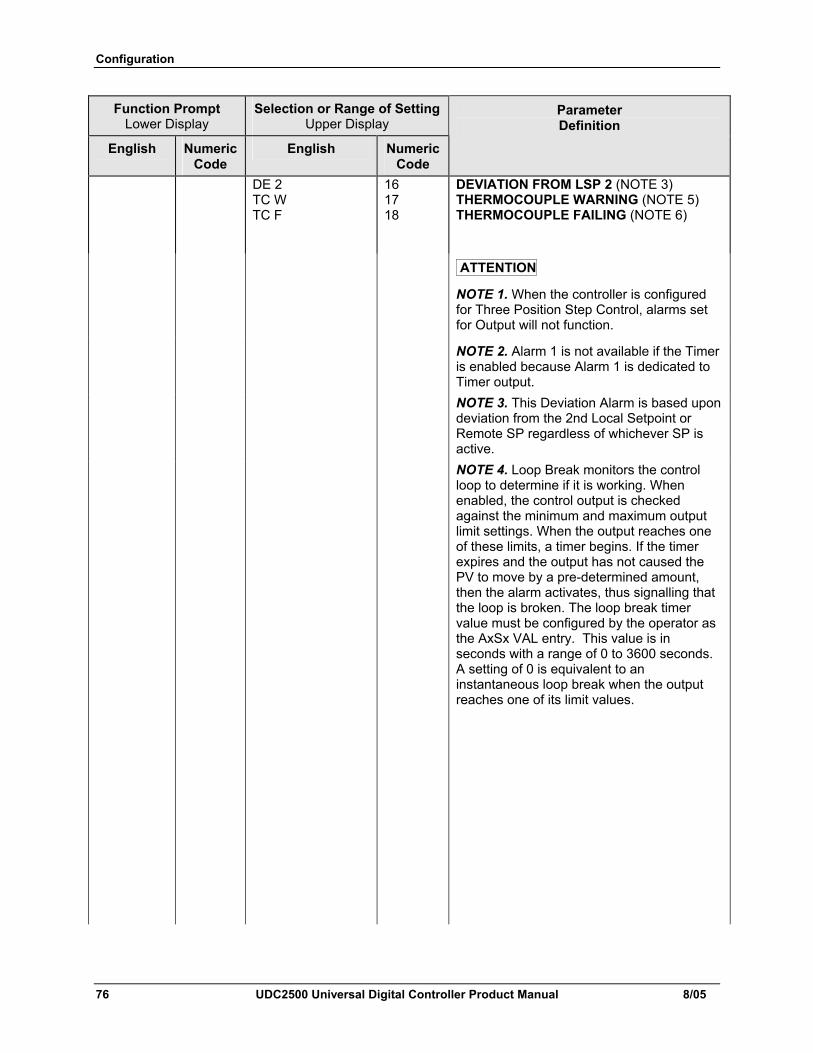
Configuration
76 UDC2500 Universal Digital Controller Product Manual 8/05
Function Prompt Lower Display
Selection or Range of Setting Upper Display
English Numeric Code
English Numeric Code
Parameter Definition
DE 2 TC W TC F
16 17 18
DEVIATION FROM LSP 2 (NOTE 3) THERMOCOUPLE WARNING (NOTE 5) THERMOCOUPLE FAILING (NOTE 6)
ATTENTION
NOTE 1. When the controller is configured for Three Position Step Control, alarms set for Output will not function.
NOTE 2. Alarm 1 is not available if the Timer is enabled because Alarm 1 is dedicated to Timer output.
NOTE 3. This Deviation Alarm is based upon deviation from the 2nd Local Setpoint or Remote SP regardless of whichever SP is active.
NOTE 4. Loop Break monitors the control loop to determine if it is working. When enabled, the control output is checked against the minimum and maximum output limit settings. When the output reaches one of these limits, a timer begins. If the timer expires and the output has not caused the PV to move by a pre-determined amount, then the alarm activates, thus signalling that the loop is broken. The loop break timer value must be configured by the operator as the AxSx VAL entry. This value is in seconds with a range of 0 to 3600 seconds. A setting of 0 is equivalent to an instantaneous loop break when the output reaches one of its limit values.
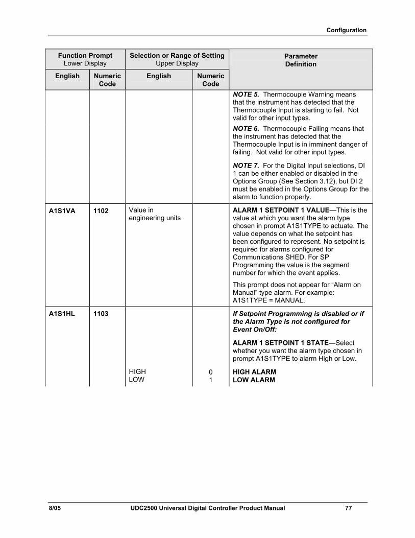
Configuration
8/05 UDC2500 Universal Digital Controller Product Manual 77
Function Prompt Lower Display
Selection or Range of Setting Upper Display
English Numeric Code
English Numeric Code
Parameter Definition
NOTE 5. Thermocouple Warning means that the instrument has detected that the Thermocouple Input is starting to fail. Not valid for other input types.
NOTE 6. Thermocouple Failing means that the instrument has detected that the Thermocouple Input is in imminent danger of failing. Not valid for other input types.
NOTE 7. For the Digital Input selections, DI 1 can be either enabled or disabled in the Options Group (See Section 3.12), but DI 2 must be enabled in the Options Group for the alarm to function properly.
A1S1VA 1102
Value in engineering units
ALARM 1 SETPOINT 1 VALUE—This is the value at which you want the alarm type chosen in prompt A1S1TYPE to actuate. The value depends on what the setpoint has been configured to represent. No setpoint is required for alarms configured for Communications SHED. For SP Programming the value is the segment number for which the event applies.
This prompt does not appear for “Alarm on Manual” type alarm. For example: A1S1TYPE = MANUAL.
A1S1HL 1103
HIGH LOW
0 1
If Setpoint Programming is disabled or if the Alarm Type is not configured for Event On/Off:
ALARM 1 SETPOINT 1 STATE—Select whether you want the alarm type chosen in prompt A1S1TYPE to alarm High or Low.
HIGH ALARM LOW ALARM
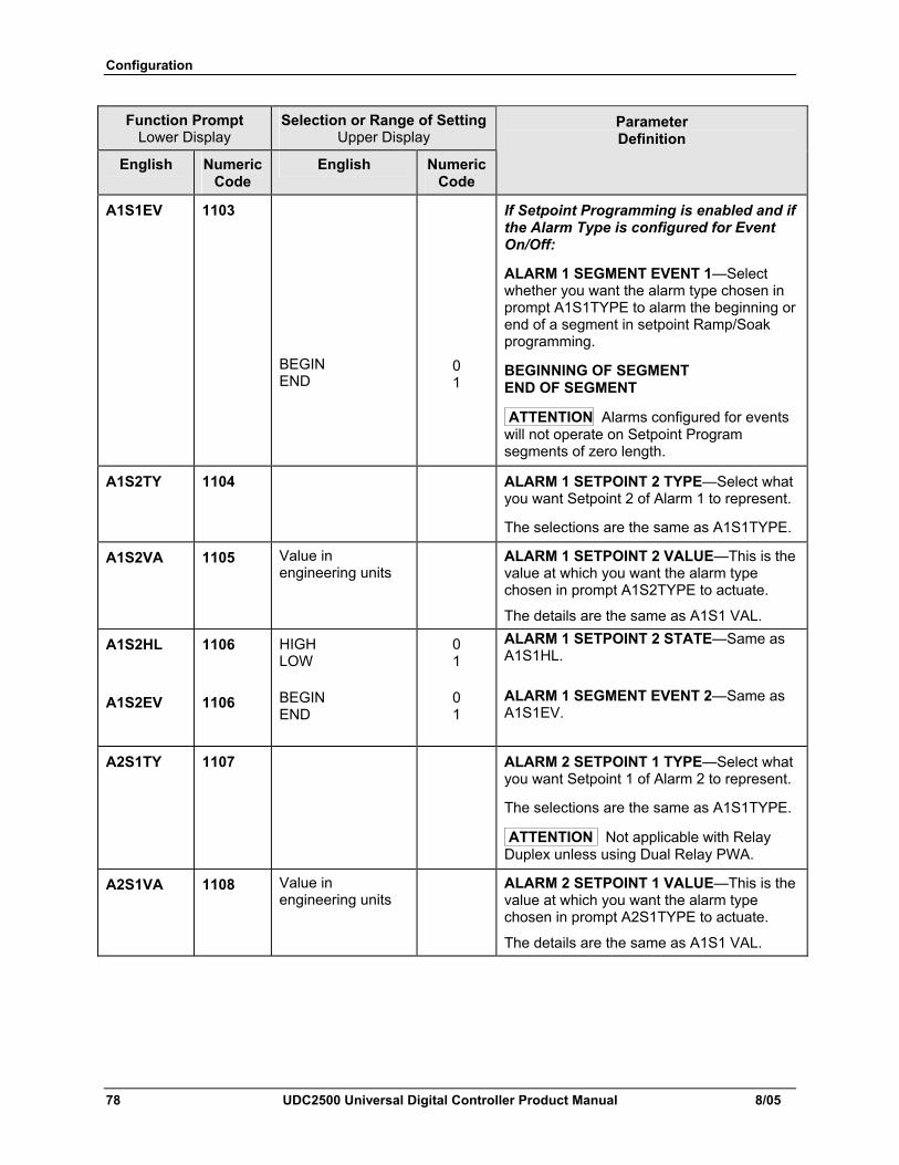
Configuration
78 UDC2500 Universal Digital Controller Product Manual 8/05
Function Prompt Lower Display
Selection or Range of Setting Upper Display
English Numeric Code
English Numeric Code
Parameter Definition
A1S1EV 1103
BEGIN END
0 1
If Setpoint Programming is enabled and if the Alarm Type is configured for Event On/Off:
ALARM 1 SEGMENT EVENT 1—Select whether you want the alarm type chosen in prompt A1S1TYPE to alarm the beginning or end of a segment in setpoint Ramp/Soak programming.
BEGINNING OF SEGMENT END OF SEGMENT
ATTENTION Alarms configured for events will not operate on Setpoint Program segments of zero length.
A1S2TY 1104 ALARM 1 SETPOINT 2 TYPE—Select what you want Setpoint 2 of Alarm 1 to represent.
The selections are the same as A1S1TYPE.
A1S2VA 1105 Value in engineering units
ALARM 1 SETPOINT 2 VALUE—This is the value at which you want the alarm type chosen in prompt A1S2TYPE to actuate.
The details are the same as A1S1 VAL.
A1S2HL
A1S2EV
1106
1106
HIGH LOW
BEGIN END
0 1
0 1
ALARM 1 SETPOINT 2 STATE—Same as A1S1HL. ALARM 1 SEGMENT EVENT 2—Same as A1S1EV.
A2S1TY 1107 ALARM 2 SETPOINT 1 TYPE—Select what you want Setpoint 1 of Alarm 2 to represent.
The selections are the same as A1S1TYPE.
ATTENTION Not applicable with Relay Duplex unless using Dual Relay PWA.
A2S1VA 1108 Value in engineering units
ALARM 2 SETPOINT 1 VALUE—This is the value at which you want the alarm type chosen in prompt A2S1TYPE to actuate.
The details are the same as A1S1 VAL.
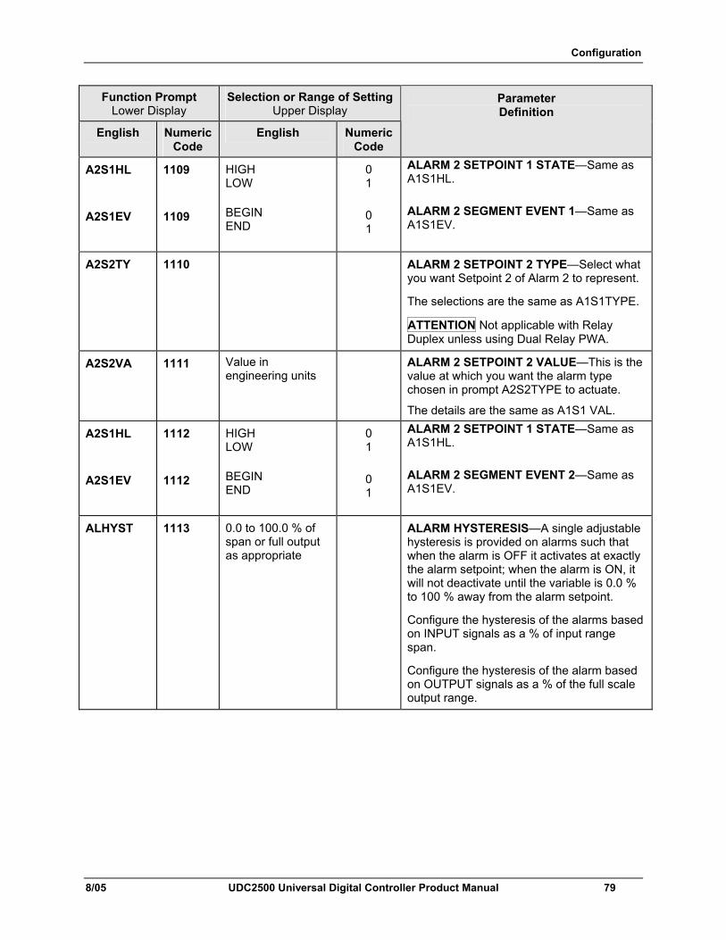
Configuration
8/05 UDC2500 Universal Digital Controller Product Manual 79
Function Prompt Lower Display
Selection or Range of Setting Upper Display
English Numeric Code
English Numeric Code
Parameter Definition
A2S1HL
A2S1EV
1109
1109
HIGH LOW
BEGIN END
0 1
0 1
ALARM 2 SETPOINT 1 STATE—Same as A1S1HL. ALARM 2 SEGMENT EVENT 1—Same as A1S1EV.
A2S2TY 1110 ALARM 2 SETPOINT 2 TYPE—Select what you want Setpoint 2 of Alarm 2 to represent.
The selections are the same as A1S1TYPE.
ATTENTION Not applicable with Relay Duplex unless using Dual Relay PWA.
A2S2VA 1111 Value in engineering units
ALARM 2 SETPOINT 2 VALUE—This is the value at which you want the alarm type chosen in prompt A2S2TYPE to actuate.
The details are the same as A1S1 VAL.
A2S1HL
A2S1EV
1112
1112
HIGH LOW
BEGIN END
0 1
0 1
ALARM 2 SETPOINT 1 STATE—Same as A1S1HL. ALARM 2 SEGMENT EVENT 2—Same as A1S1EV.
ALHYST 1113 0.0 to 100.0 % of span or full output as appropriate
ALARM HYSTERESIS—A single adjustable hysteresis is provided on alarms such that when the alarm is OFF it activates at exactly the alarm setpoint; when the alarm is ON, it will not deactivate until the variable is 0.0 % to 100 % away from the alarm setpoint.
Configure the hysteresis of the alarms based on INPUT signals as a % of input range span.
Configure the hysteresis of the alarm based on OUTPUT signals as a % of the full scale output range.
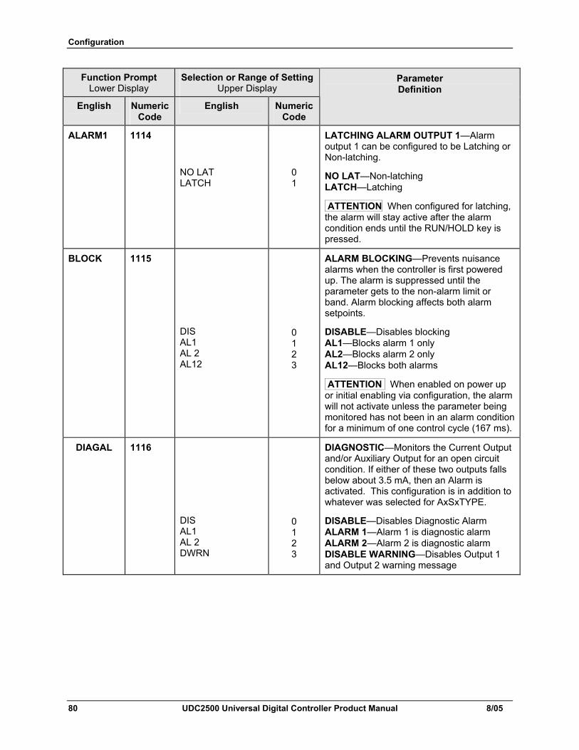
Configuration
80 UDC2500 Universal Digital Controller Product Manual 8/05
Function Prompt Lower Display
Selection or Range of Setting Upper Display
English Numeric Code
English Numeric Code
Parameter Definition
ALARM1 1114
NO LAT LATCH
0 1
LATCHING ALARM OUTPUT 1—Alarm output 1 can be configured to be Latching or Non-latching.
NO LAT—Non-latching LATCH—Latching
ATTENTION When configured for latching, the alarm will stay active after the alarm condition ends until the RUN/HOLD key is pressed.
BLOCK 1115 DIS AL1 AL 2 AL12
0 1 2 3
ALARM BLOCKING—Prevents nuisance alarms when the controller is first powered up. The alarm is suppressed until the parameter gets to the non-alarm limit or band. Alarm blocking affects both alarm setpoints.
DISABLE—Disables blocking AL1—Blocks alarm 1 only AL2—Blocks alarm 2 only AL12—Blocks both alarms
ATTENTION When enabled on power up or initial enabling via configuration, the alarm will not activate unless the parameter being monitored has not been in an alarm condition for a minimum of one control cycle (167 ms).
DIAGAL 1116 DIS AL1 AL 2 DWRN
0 1 2 3
DIAGNOSTIC—Monitors the Current Output and/or Auxiliary Output for an open circuit condition. If either of these two outputs falls below about 3.5 mA, then an Alarm is activated. This configuration is in addition to whatever was selected for AxSxTYPE.
DISABLE—Disables Diagnostic Alarm ALARM 1—Alarm 1 is diagnostic alarm ALARM 2—Alarm 2 is diagnostic alarm DISABLE WARNING—Disables Output 1 and Output 2 warning message
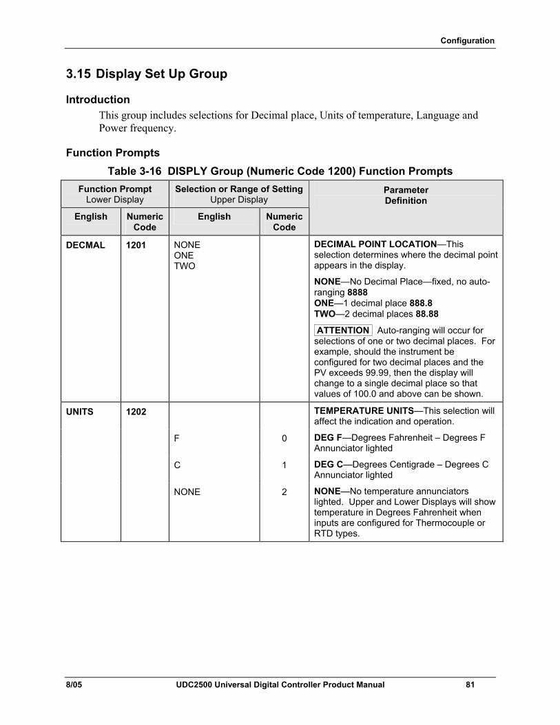
Configuration
8/05 UDC2500 Universal Digital Controller Product Manual 81
3.15 Display Set Up Group
Introduction This group includes selections for Decimal place, Units of temperature, Language and Power frequency.
Function Prompts Table 3-16 DISPLY Group (Numeric Code 1200) Function Prompts
Function Prompt Lower Display
Selection or Range of Setting Upper Display
English Numeric Code
English Numeric Code
Parameter Definition
DECMAL 1201 NONE ONE TWO
DECIMAL POINT LOCATION—This selection determines where the decimal point appears in the display.
NONE—No Decimal Place—fixed, no auto-ranging 8888 ONE—1 decimal place 888.8 TWO—2 decimal places 88.88
ATTENTION Auto-ranging will occur for selections of one or two decimal places. For example, should the instrument be configured for two decimal places and the PV exceeds 99.99, then the display will change to a single decimal place so that values of 100.0 and above can be shown.
UNITS 1202 TEMPERATURE UNITS—This selection will affect the indication and operation.
F 0 DEG F—Degrees Fahrenheit – Degrees F Annunciator lighted
C 1 DEG C—Degrees Centigrade – Degrees C Annunciator lighted
NONE 2 NONE—No temperature annunciators lighted. Upper and Lower Displays will show temperature in Degrees Fahrenheit when inputs are configured for Thermocouple or RTD types.
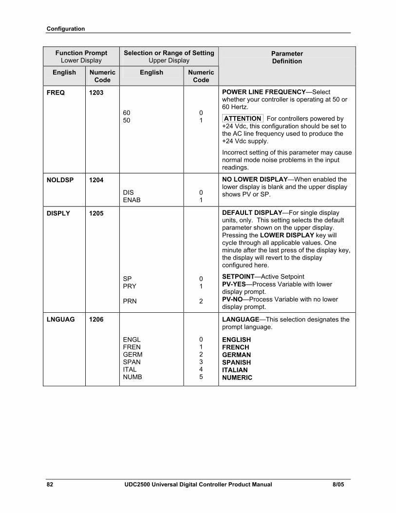
Configuration
82 UDC2500 Universal Digital Controller Product Manual 8/05
Function Prompt Lower Display
Selection or Range of Setting Upper Display
English Numeric Code
English Numeric Code
Parameter Definition
FREQ 1203
60 50
0 1
POWER LINE FREQUENCY—Select whether your controller is operating at 50 or 60 Hertz.
ATTENTION For controllers powered by +24 Vdc, this configuration should be set to the AC line frequency used to produce the +24 Vdc supply.
Incorrect setting of this parameter may cause normal mode noise problems in the input readings.
NOLDSP 1204
DIS ENAB
0 1
NO LOWER DISPLAY—When enabled the lower display is blank and the upper display shows PV or SP.
DISPLY 1205
SP PRY PRN
0 1
2
DEFAULT DISPLAY—For single display units, only. This setting selects the default parameter shown on the upper display. Pressing the LOWER DISPLAY key will cycle through all applicable values. One minute after the last press of the display key, the display will revert to the display configured here.
SETPOINT—Active Setpoint PV-YES—Process Variable with lower display prompt. PV-NO—Process Variable with no lower display prompt.
LNGUAG 1206
ENGL FREN GERM SPAN ITAL NUMB
0 1 2 3 4 5
LANGUAGE—This selection designates the prompt language.
ENGLISH FRENCH GERMAN SPANISH ITALIAN NUMERIC
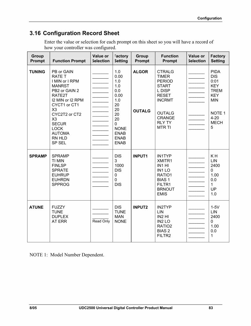
Configuration
8/05 UDC2500 Universal Digital Controller Product Manual 83
3.16 Configuration Record Sheet Enter the value or selection for each prompt on this sheet so you will have a record of how your controller was configured.
Group Prompt
Function Prompt
Value or Selection
Factory Setting
Group Prompt
Function Prompt
Value or Selection
Factory Setting
TUNING PB or GAIN RATE T I MIN or I RPM MANRST PB2 or GAIN 2 RATE2T I2 MIN or I2 RPM CYCT1 or CT1 X3 CYC2T2 or CT2 X3 SECUR LOCK AUTOMA RN HLD SP SEL
_______ _______ _______ _______ _______ _______ _______ _______ _______ _______ _______ _______ _______ _______ _______ _______
1.0 0.00 1.0 1.0 0.0 0.00 1.0 20 20 20 20 0 NONE ENAB ENAB ENAB
ALGOR
OUTALG
CTRALG TIMER PERIOD START L DISP RESET INCRMT
OUTALG CRANGE RLY TY MTR TI
_______ _______ _______ _______ _______ _______ _______
_______ _______ _______ _______
PIDA DIS 0:01 KEY TREM KEY MIN
NOTE 1 4-20 MECH 5
SPRAMP SPRAMP TI MIN FINLSP SPRATE EUHRUP EUHRDN SPPROG
_______ _______ _______ _______ _______ _______ _______
DIS 3 1000 DIS 0 0 DIS
INPUT1 IN1TYP XMITR1 IN1 HI IN1 LO RATIO1 BIAS 1 FILTR1 BRNOUT EMIS
_______ _______ _______ _______ _______ _______ _______ _______ _______
K H LIN 2400 0 1.00 0.0 1 UP 1.0
ATUNE FUZZY TUNE DUPLEX AT ERR
_______ _______ _______ Read Only
DIS TUNE MAN NONE
INPUT2 IN2TYP LIN IN2 HI IN2 LO RATIO2 BIAS 2 FILTR2
_______ _______ _______ _______ _______ _______ _______
1-5V LIN 2400 0 1.00 0.0 1
NOTE 1: Model Number Dependent.
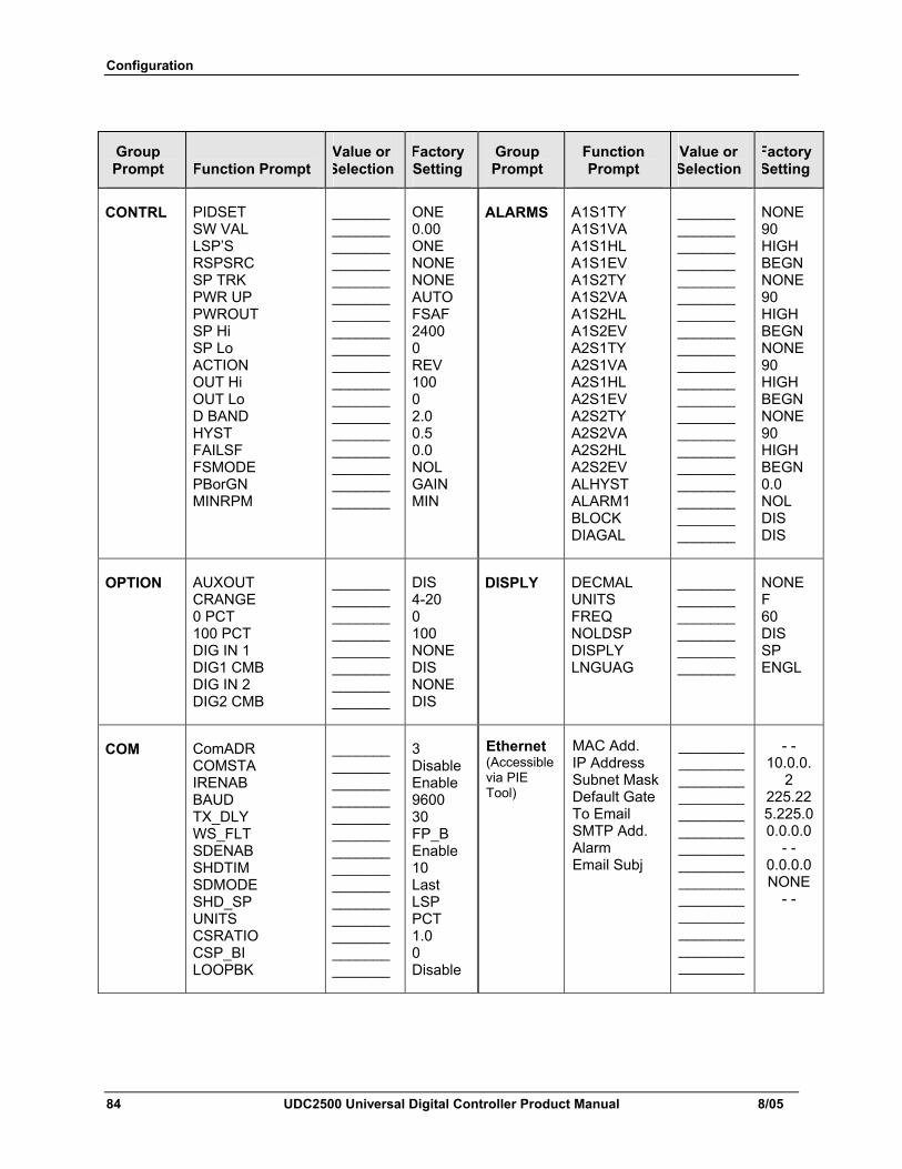
Configuration
84 UDC2500 Universal Digital Controller Product Manual 8/05
Group Prompt
Function Prompt
Value or Selection
Factory Setting
Group Prompt
Function Prompt
Value or Selection
Factory Setting
CONTRL PIDSET SW VAL LSP’S RSPSRC SP TRK PWR UP PWROUT SP Hi SP Lo ACTION OUT Hi OUT Lo D BAND HYST FAILSF FSMODE PBorGN MINRPM
_______ _______ _______ _______ _______ _______ _______ _______ _______ _______ _______ _______ _______ _______ _______ _______ _______ _______
ONE 0.00 ONE NONE NONE AUTO FSAF 2400 0 REV 100 0 2.0 0.5 0.0 NOL GAIN MIN
ALARMS A1S1TY A1S1VA A1S1HL A1S1EV A1S2TY A1S2VA A1S2HL A1S2EV A2S1TY A2S1VA A2S1HL A2S1EV A2S2TY A2S2VA A2S2HL A2S2EV ALHYST ALARM1 BLOCK DIAGAL
_______ _______ _______ _______ _______ _______ _______ _______ _______ _______ _______ _______ _______ _______ _______ _______ _______ _______ _______ _______
NONE 90 HIGH BEGN NONE 90 HIGH BEGN NONE 90 HIGH BEGN NONE 90 HIGH BEGN 0.0 NOL DIS DIS
OPTION AUXOUT CRANGE 0 PCT 100 PCT DIG IN 1 DIG1 CMB DIG IN 2 DIG2 CMB
_______ _______ _______ _______ _______ _______ _______ _______
DIS 4-20 0 100 NONE DIS NONE DIS
DISPLY DECMAL UNITS FREQ NOLDSP DISPLY LNGUAG
_______ _______ _______ _______ _______ _______
NONE F 60 DIS SP ENGL
COM ComADR COMSTA IRENAB BAUD TX_DLY WS_FLT SDENAB SHDTIM SDMODE SHD_SP UNITS CSRATIO CSP_BI LOOPBK
_______ _______ _______ _______ _______ _______ _______ _______ _______ _______ _______ _______ _______ _______
3 DisableEnable 9600 30 FP_B Enable 10 Last LSP PCT 1.0 0 Disable
Ethernet (Accessible via PIE Tool)
MAC Add. IP Address Subnet Mask Default Gate To Email SMTP Add. Alarm Email Subj
________________________________________________________________________________________________________________
- - 10.0.0.
2 225.225.225.00.0.0.0
- - 0.0.0.0NONE
- -
Monitoring and Operating the Controller
8/05 UDC2500 Universal Digital Controller Product Manual 85
4 Monitoring and Operating the Controller
4.1 Overview
Introduction This section gives you all the information necessary to help you monitor and operate your controller including an Operator Interface overview, how to lockout changes to the controller, entering a security code, and monitoring the displays.
What's in this section? The following topics are covered in this section.
TOPIC See Page 4.1 Overview 85 4.2 Operator Interface 86 4.3 Entering A Security Code 86 4.4 Lockout Feature 87 4.5 Monitoring The Controller 89 4.6 Single Display Functionality 93 4.7 Start Up Procedure for Operation 92 4.8 Control Modes 96 4.9 Setpoints 97 4.10 Timer 98 4.11 Accutune 100 4.12 Fuzzy Overshoot Suppression 106 4.13 Using Two Sets Of Tuning Constants 106 4.14 Alarm Setpoints 108 4.15 Three Position Step Control Algorithm 109 4.16 Setting A Failsafe Output Value For Restart After A Power Loss 110 4.17 Setting Failsafe Mode 111 4.18 Setpoint Rate/Ramp/Program Overview 111 4.20 Setpoint Rate 113 4.19 Setpoint Ramp 112 4.21 Setpoint Ramp/Soak Programming 114
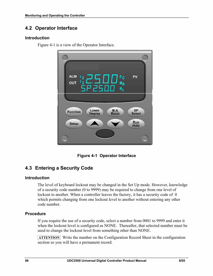
Monitoring and Operating the Controller
86 UDC2500 Universal Digital Controller Product Manual 8/05
4.2 Operator Interface
Introduction Figure 4-1 is a view of the Operator Interface.
Figure 4-1 Operator Interface
4.3 Entering a Security Code
Introduction The level of keyboard lockout may be changed in the Set Up mode. However, knowledge of a security code number (0 to 9999) may be required to change from one level of lockout to another. When a controller leaves the factory, it has a security code of 0 which permits changing from one lockout level to another without entering any other code number.
Procedure If you require the use of a security code, select a number from 0001 to 9999 and enter it when the lockout level is configured as NONE. Thereafter, that selected number must be used to change the lockout level from something other than NONE.
ATTENTION Write the number on the Configuration Record Sheet in the configuration section so you will have a permanent record.
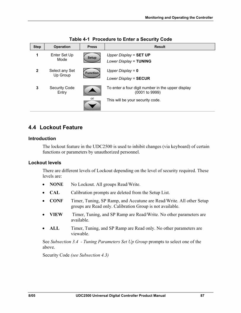
Monitoring and Operating the Controller
8/05 UDC2500 Universal Digital Controller Product Manual 87
Table 4-1 Procedure to Enter a Security Code Step Operation Press Result
1 Enter Set Up Mode SetupSetup
Upper Display = SET UP Lower Display = TUNING
2 Select any Set Up Group FunctionFunctionFunction
Upper Display = 0
Lower Display = SECUR
3 Security Code Entry
or
To enter a four digit number in the upper display (0001 to 9999)
This will be your security code.
4.4 Lockout Feature
Introduction The lockout feature in the UDC2500 is used to inhibit changes (via keyboard) of certain functions or parameters by unauthorized personnel.
Lockout levels There are different levels of Lockout depending on the level of security required. These levels are:
• NONE No Lockout. All groups Read/Write.
• CAL Calibration prompts are deleted from the Setup List.
• CONF Timer, Tuning, SP Ramp, and Accutune are Read/Write. All other Setup groups are Read only. Calibration Group is not available.
• VIEW Timer, Tuning, and SP Ramp are Read/Write. No other parameters are available.
• ALL Timer, Tuning, and SP Ramp are Read only. No other parameters are viewable.
See Subsection 3.4 - Tuning Parameters Set Up Group prompts to select one of the above.
Security Code (see Subsection 4.3)
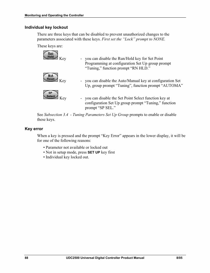
Monitoring and Operating the Controller
88 UDC2500 Universal Digital Controller Product Manual 8/05
Individual key lockout There are three keys that can be disabled to prevent unauthorized changes to the parameters associated with these keys. First set the “Lock” prompt to NONE.
These keys are:
RunHoldRunHoldRunHold Key - you can disable the Run/Hold key for Set Point
Programming at configuration Set Up group prompt “Tuning,” function prompt “RN HLD.”
M-AResetM-A
ResetM-A
Reset Key - you can disable the Auto/Manual key at configuration Set Up, group prompt “Tuning”, function prompt “AUTOMA”
SP Select
SP Select
SP Select Key - you can disable the Set Point Select function key at
configuration Set Up group prompt “Tuning,” function prompt “SP SEL.”
See Subsection 3.4 - Tuning Parameters Set Up Group prompts to enable or disable these keys.
Key error When a key is pressed and the prompt “Key Error” appears in the lower display, it will be for one of the following reasons:
• Parameter not available or locked out • Not in setup mode, press SET UP key first • Individual key locked out.
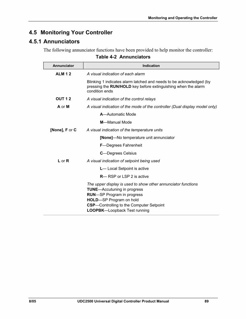
Monitoring and Operating the Controller
8/05 UDC2500 Universal Digital Controller Product Manual 89
4.5 Monitoring Your Controller 4.5.1 Annunciators
The following annunciator functions have been provided to help monitor the controller: Table 4-2 Annunciators
Annunciator Indication
ALM 1 2
A visual indication of each alarm
Blinking 1 indicates alarm latched and needs to be acknowledged (by pressing the RUN/HOLD key before extinguishing when the alarm condition ends
OUT 1 2 A visual indication of the control relays
A or M A visual indication of the mode of the controller (Dual display model only)
A—Automatic Mode
M—Manual Mode
[None], F or C A visual indication of the temperature units
[None]—No temperature unit annunciator
F—Degrees Fahrenheit
C—Degrees Celsius
L or R A visual indication of setpoint being used
L— Local Setpoint is active
R— RSP or LSP 2 is active
The upper display is used to show other annunciator functions TUNE—Accutuning in progress RUN—SP Program in progress HOLD—SP Program on hold CSP—Controlling to the Computer Setpoint LOOPBK—Loopback Test running
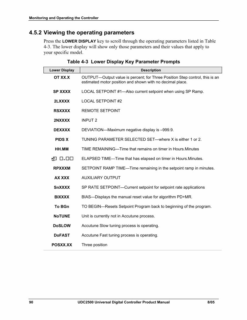
Monitoring and Operating the Controller
90 UDC2500 Universal Digital Controller Product Manual 8/05
4.5.2 Viewing the operating parameters Press the LOWER DISPLAY key to scroll through the operating parameters listed in Table 4-3. The lower display will show only those parameters and their values that apply to your specific model.
Table 4-3 Lower Display Key Parameter Prompts Lower Display Description
OT XX.X OUTPUT—Output value is percent; for Three Position Step control, this is an estimated motor position and shown with no decimal place.
SP XXXX LOCAL SETPOINT #1—Also current setpoint when using SP Ramp.
2LXXXX LOCAL SETPOINT #2
RSXXXX REMOTE SETPOINT
2NXXXX INPUT 2
DEXXXX DEVIATION—Maximum negative display is –999.9.
PIDS X TUNING PARAMETER SELECTED SET—where X is either 1 or 2.
HH.MM TIME REMAINING—Time that remains on timer in Hours.Minutes
ELAPSED TIME—Time that has elapsed on timer in Hours.Minutes.
RPXXXM SETPOINT RAMP TIME—Time remaining in the setpoint ramp in minutes.
AX XXX AUXILIARY OUTPUT
SnXXXX SP RATE SETPOINT—Current setpoint for setpoint rate applications
BIXXXX BIAS—Displays the manual reset value for algorithm PD+MR.
To BGn TO BEGIN—Resets Setpoint Program back to beginning of the program.
NoTUNE Unit is currently not in Accutune process.
DoSLOW Accutune Slow tuning process is operating.
DoFAST Accutune Fast tuning process is operating.
POSXX.XX Three position
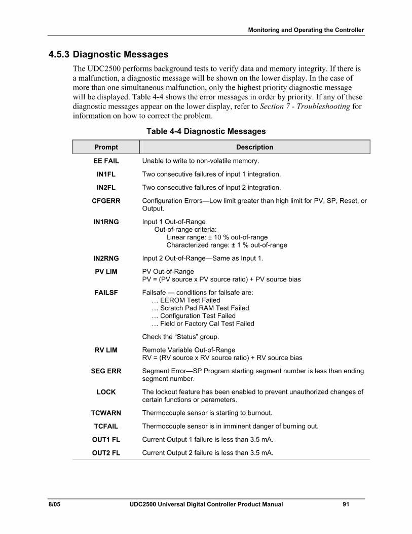
Monitoring and Operating the Controller
8/05 UDC2500 Universal Digital Controller Product Manual 91
4.5.3 Diagnostic Messages The UDC2500 performs background tests to verify data and memory integrity. If there is a malfunction, a diagnostic message will be shown on the lower display. In the case of more than one simultaneous malfunction, only the highest priority diagnostic message will be displayed. Table 4-4 shows the error messages in order by priority. If any of these diagnostic messages appear on the lower display, refer to Section 7 - Troubleshooting for information on how to correct the problem.
Table 4-4 Diagnostic Messages
Prompt Description
EE FAIL Unable to write to non-volatile memory.
IN1FL Two consecutive failures of input 1 integration.
IN2FL Two consecutive failures of input 2 integration.
CFGERR Configuration Errors—Low limit greater than high limit for PV, SP, Reset, or Output.
IN1RNG Input 1 Out-of-Range Out-of-range criteria: Linear range: ± 10 % out-of-range Characterized range: ± 1 % out-of-range
IN2RNG Input 2 Out-of-Range—Same as Input 1.
PV LIM PV Out-of-Range PV = (PV source x PV source ratio) + PV source bias
FAILSF Failsafe — conditions for failsafe are: … EEROM Test Failed … Scratch Pad RAM Test Failed … Configuration Test Failed … Field or Factory Cal Test Failed
Check the “Status” group.
RV LIM Remote Variable Out-of-Range RV = (RV source x RV source ratio) + RV source bias
SEG ERR Segment Error—SP Program starting segment number is less than ending segment number.
LOCK The lockout feature has been enabled to prevent unauthorized changes of certain functions or parameters.
TCWARN Thermocouple sensor is starting to burnout.
TCFAIL Thermocouple sensor is in imminent danger of burning out.
OUT1 FL Current Output 1 failure is less than 3.5 mA.
OUT2 FL Current Output 2 failure is less than 3.5 mA.
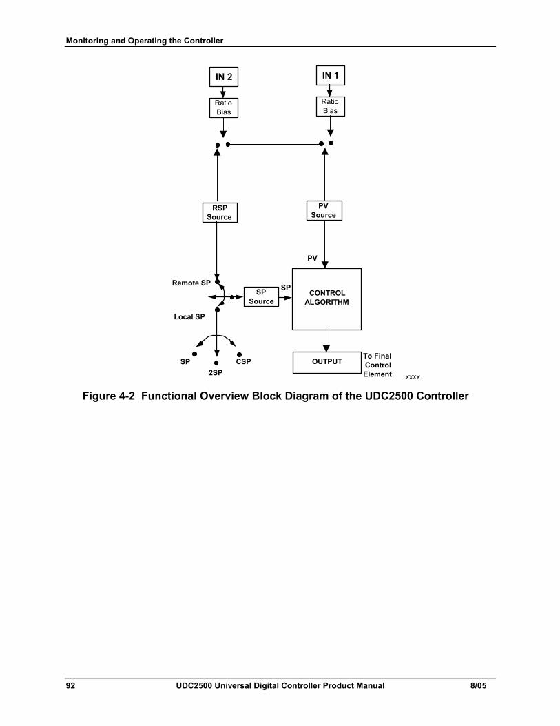
Monitoring and Operating the Controller
92 UDC2500 Universal Digital Controller Product Manual 8/05
XXXX
IN 1
Ratio Bias
IN 2
Ratio Bias
PV Source
RSP Source
SP Source
SP
PV
Remote SP
Local SP
SP 2SP
CONTROL ALGORITHM
OUTPUTTo Final Control Element
CSP
Figure 4-2 Functional Overview Block Diagram of the UDC2500 Controller
Monitoring and Operating the Controller
8/05 UDC2500 Universal Digital Controller Product Manual 93
4.6 Single Display Functionality
Introduction This means that the displayed value of PV, Setpoint, Setpoint2, Remote Setpoint, Input 2, Output, Bias, Aux Out, and Deviation will appear on the top display and a prompt identifying the value will appear on the bottom display.
Access the Values Pressing the LOWER DISPLAY key will cycle through all applicable values (configuration dependent). One minute after the last press of the display key, the display will revert back to a configured default display. The default display is configured in the Input 1 Setup Group, and has three selections:
• Active Setpoint (SP)
• Process Variable (PR Y)
• Process Variable with no bottom display prompt (PR n).
Exceptions There are three exceptions to the above rules. The displays for PID SET, Timer and Setpoint Ramp will appear the same as on a dual display model and, when displaying Timer or Ramp values, the default display switchover feature is disabled.
Auto-only Mode The single display model is Auto only mode. The Auto/Manual key has no effect on controller mode. As a result of this, the failsafe mode is always non-latching.
While a failsafe condition exists, the controller output will assume the failsafe value. When the failsafe condition goes away, normal automatic operation continues.
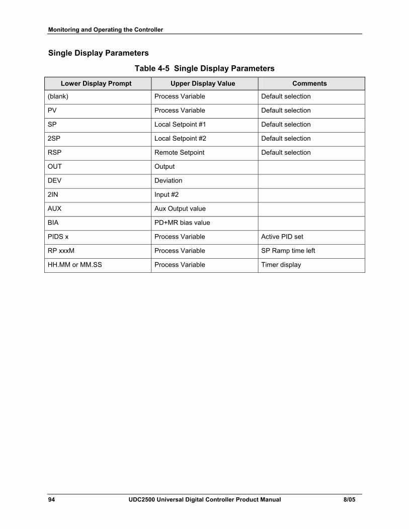
Monitoring and Operating the Controller
94 UDC2500 Universal Digital Controller Product Manual 8/05
Single Display Parameters
Table 4-5 Single Display Parameters
Lower Display Prompt Upper Display Value Comments
(blank) Process Variable Default selection
PV Process Variable Default selection
SP Local Setpoint #1 Default selection
2SP Local Setpoint #2 Default selection
RSP Remote Setpoint Default selection
OUT Output
DEV Deviation
2IN Input #2
AUX Aux Output value
BIA PD+MR bias value
PIDS x Process Variable Active PID set
RP xxxM Process Variable SP Ramp time left
HH.MM or MM.SS Process Variable Timer display
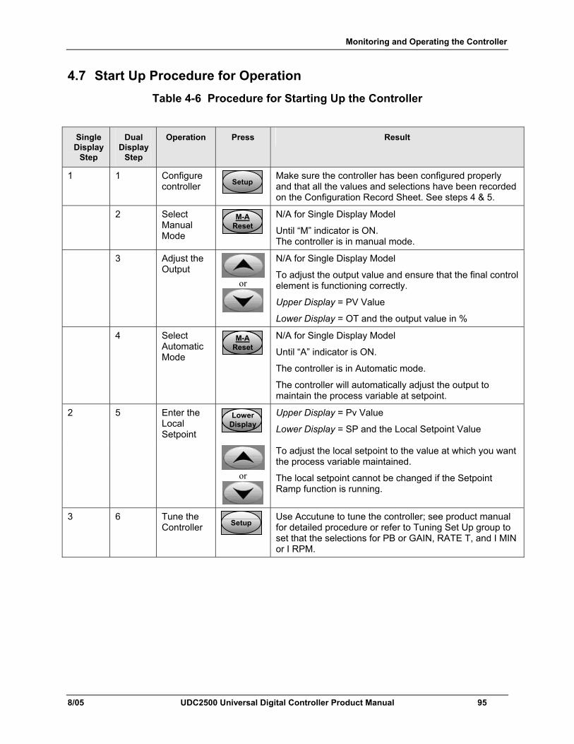
Monitoring and Operating the Controller
8/05 UDC2500 Universal Digital Controller Product Manual 95
4.7 Start Up Procedure for Operation Table 4-6 Procedure for Starting Up the Controller
Single Display
Step
Dual Display
Step
Operation Press Result
1 1 Configure controller SetupSetup
Make sure the controller has been configured properly and that all the values and selections have been recorded on the Configuration Record Sheet. See steps 4 & 5.
2 Select Manual Mode
M-AResetM-A
ResetM-A
Reset
N/A for Single Display Model
Until “M” indicator is ON. The controller is in manual mode.
3 Adjust the Output
or
N/A for Single Display Model
To adjust the output value and ensure that the final control element is functioning correctly.
Upper Display = PV Value
Lower Display = OT and the output value in %
4 Select Automatic Mode
M-AResetM-A
ResetM-A
Reset
N/A for Single Display Model
Until “A” indicator is ON.
The controller is in Automatic mode.
The controller will automatically adjust the output to maintain the process variable at setpoint.
2 5 Enter the Local Setpoint
LowerDisplayLower
DisplayLower
Display
Upper Display = Pv Value
Lower Display = SP and the Local Setpoint Value
or
To adjust the local setpoint to the value at which you want the process variable maintained.
The local setpoint cannot be changed if the Setpoint Ramp function is running.
3 6 Tune the Controller SetupSetup
Use Accutune to tune the controller; see product manual for detailed procedure or refer to Tuning Set Up group to set that the selections for PB or GAIN, RATE T, and I MIN or I RPM.
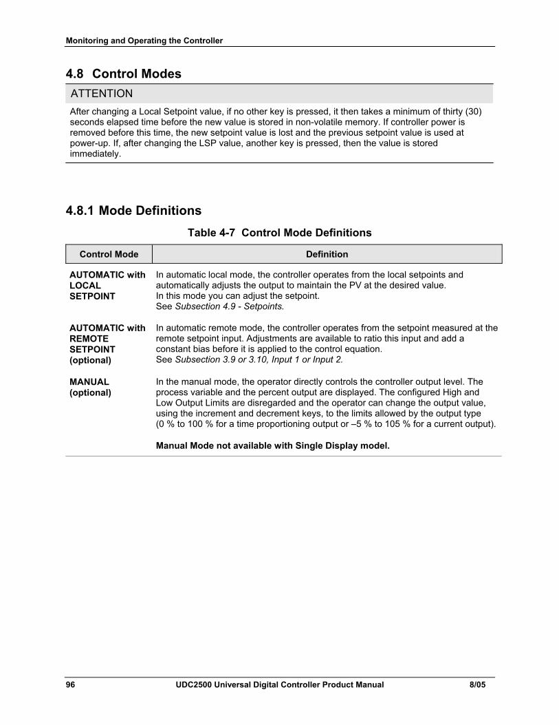
Monitoring and Operating the Controller
96 UDC2500 Universal Digital Controller Product Manual 8/05
4.8 Control Modes ATTENTION After changing a Local Setpoint value, if no other key is pressed, it then takes a minimum of thirty (30) seconds elapsed time before the new value is stored in non-volatile memory. If controller power is removed before this time, the new setpoint value is lost and the previous setpoint value is used at power-up. If, after changing the LSP value, another key is pressed, then the value is stored immediately.
4.8.1 Mode Definitions Table 4-7 Control Mode Definitions
Control Mode Definition
AUTOMATIC with LOCAL SETPOINT
In automatic local mode, the controller operates from the local setpoints and automatically adjusts the output to maintain the PV at the desired value. In this mode you can adjust the setpoint. See Subsection 4.9 - Setpoints.
AUTOMATIC with REMOTE SETPOINT (optional)
In automatic remote mode, the controller operates from the setpoint measured at the remote setpoint input. Adjustments are available to ratio this input and add a constant bias before it is applied to the control equation. See Subsection 3.9 or 3.10, Input 1 or Input 2.
MANUAL (optional)
In the manual mode, the operator directly controls the controller output level. The process variable and the percent output are displayed. The configured High and Low Output Limits are disregarded and the operator can change the output value, using the increment and decrement keys, to the limits allowed by the output type (0 % to 100 % for a time proportioning output or –5 % to 105 % for a current output).
Manual Mode not available with Single Display model.
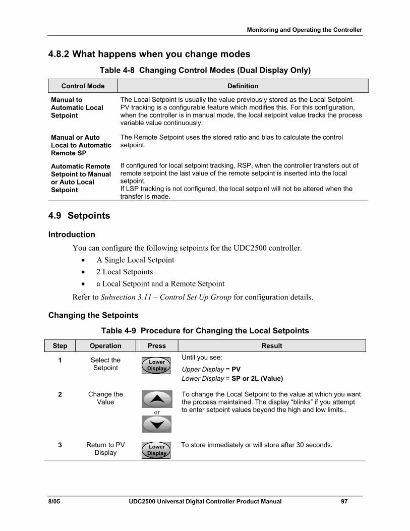
Monitoring and Operating the Controller
8/05 UDC2500 Universal Digital Controller Product Manual 97
4.8.2 What happens when you change modes Table 4-8 Changing Control Modes (Dual Display Only)
Control Mode Definition
Manual to Automatic Local Setpoint
The Local Setpoint is usually the value previously stored as the Local Setpoint. PV tracking is a configurable feature which modifies this. For this configuration, when the controller is in manual mode, the local setpoint value tracks the process variable value continuously.
Manual or Auto Local to Automatic Remote SP
The Remote Setpoint uses the stored ratio and bias to calculate the control setpoint.
Automatic Remote Setpoint to Manual or Auto Local Setpoint
If configured for local setpoint tracking, RSP, when the controller transfers out of remote setpoint the last value of the remote setpoint is inserted into the local setpoint. If LSP tracking is not configured, the local setpoint will not be altered when the transfer is made.
4.9 Setpoints
Introduction You can configure the following setpoints for the UDC2500 controller.
• A Single Local Setpoint • 2 Local Setpoints • a Local Setpoint and a Remote Setpoint
Refer to Subsection 3.11 – Control Set Up Group for configuration details.
Changing the Setpoints
Table 4-9 Procedure for Changing the Local Setpoints
Step Operation Press Result
1 Select the Setpoint
LowerDisplayLower
DisplayLower
Display
Until you see:
Upper Display = PV Lower Display = SP or 2L (Value)
2 Change the Value
or
To change the Local Setpoint to the value at which you want the process maintained. The display “blinks” if you attempt to enter setpoint values beyond the high and low limits..
3 Return to PV Display
LowerDisplayLower
DisplayLower
Display
To store immediately or will store after 30 seconds.
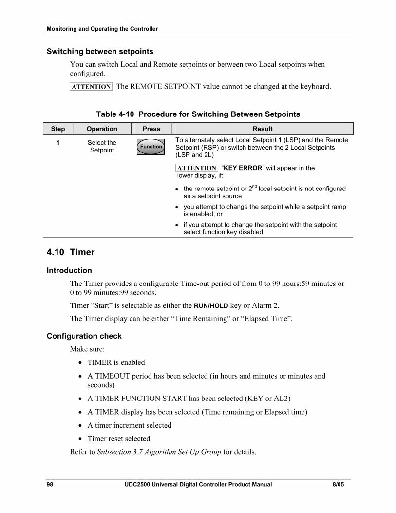
Monitoring and Operating the Controller
98 UDC2500 Universal Digital Controller Product Manual 8/05
Switching between setpoints You can switch Local and Remote setpoints or between two Local setpoints when configured.
ATTENTION The REMOTE SETPOINT value cannot be changed at the keyboard.
Table 4-10 Procedure for Switching Between Setpoints
Step Operation Press Result
1 Select the Setpoint FunctionFunctionFunction
To alternately select Local Setpoint 1 (LSP) and the Remote Setpoint (RSP) or switch between the 2 Local Setpoints (LSP and 2L)
ATTENTION “KEY ERROR” will appear in the lower display, if:
• the remote setpoint or 2nd local setpoint is not configured as a setpoint source
• you attempt to change the setpoint while a setpoint ramp is enabled, or
• if you attempt to change the setpoint with the setpoint select function key disabled.
4.10 Timer
Introduction The Timer provides a configurable Time-out period of from 0 to 99 hours:59 minutes or 0 to 99 minutes:99 seconds.
Timer “Start” is selectable as either the RUN/HOLD key or Alarm 2.
The Timer display can be either “Time Remaining” or “Elapsed Time”.
Configuration check Make sure:
• TIMER is enabled
• A TIMEOUT period has been selected (in hours and minutes or minutes and seconds)
• A TIMER FUNCTION START has been selected (KEY or AL2)
• A TIMER display has been selected (Time remaining or Elapsed time)
• A timer increment selected
• Timer reset selected
Refer to Subsection 3.7 Algorithm Set Up Group for details.
Monitoring and Operating the Controller
8/05 UDC2500 Universal Digital Controller Product Manual 99
Viewing Times The times are viewed on the lower display as follows:
TIME REMAINING will show as a decreasing Hrs:Min value (HH:MM) or Min:Sec value (MM:SS) plus a counterclockwise rotating clock face.
ELAPSED TIME will show as an increasing Hrs:Min value(HH:MM) or Min:Sec value (MM:SS) plus a clockwise rotating clock face.
Operation When the Timer is enabled (RUN/HOLD key or ALARM 2), it has exclusive control of Alarm 1 relay.
At “TIME-OUT:
• Alarm 1 is active
• The clock character has stopped moving
• The Time display shows either 00:00 or the time-out period depending on the configuration selection
• The Timer is ready to be reset
At “RESET”:
• Alarm 1 relay is inactive
• The time display shows the time-out period
• The time-out period can be changed at this time using the or keys.
• The Timer is ready to be activated
Monitoring and Operating the Controller
100 UDC2500 Universal Digital Controller Product Manual 8/05
4.11 Accutune III
Introduction Accutune III (TUNE) may be used for self-regulating and single integrating processes. This autotuning method is initiated on-demand, typically at initial start-up.
There are no other requirements necessary, such as prior knowledge to the process dynamics or initial or post tune process line-out to setpoint or manual output.
Also, the setpoint value is not required to change in order to initiate the tuning process, but the controller must be in the Automatic mode to start tuning. The process need not be in a static (lined out) state and may be dynamic (changing with a steady output).
Configuration check Make sure:
• TUNE has been enabled see to Subsection 3.6 - Accutune Set Up Group for details.
Tuning indicators “TUNE” will flash in the upper display until tuning is completed.
Operation The “TUNE” (Accutune II) algorithm provides user-friendly, on-demand tuning in this controller. No knowledge of the process is required at start-up. The operator simply initiates the tuning while in the automatic mode.
Once Accutune III has been enabled in the TUNE setup group, either “SLOW” or “FAST” tuning may be used. Which one is used is selected via the lower display during normal operation.
For the SLOW selection, the controller calculates conservative tuning constants with the objective of minimizing overshoot. If the controller determines that the process has appreciable dead time, it will automatically default to use Dahlin Tuning, which produces very conservative tuning constants. The SLOW selection may be useful for TPSC applications, as it reduces any “hunt” problems for the motor.
For the FAST selection, the controller calculates aggressive tuning constants with the objective of producing quarter damped response. Depending upon the process, this selection will usually result in some overshoot. For this reason, it may be desireable to enable the FUZZY tune selection. See Section 4.12. When Fuzzy tune is enabled, it will work to suppress or eliminate any overshoot that may occur as a result of the calculated tuning parameters as the PV approaches the setpoint.
The TUNE process will cycle the controller’s output two full cycles between the low and high output limits while allowing only a very small Process Variable change above and below the SP during each cycle. “TUNE” flashes in the upper display until tuning is completed.
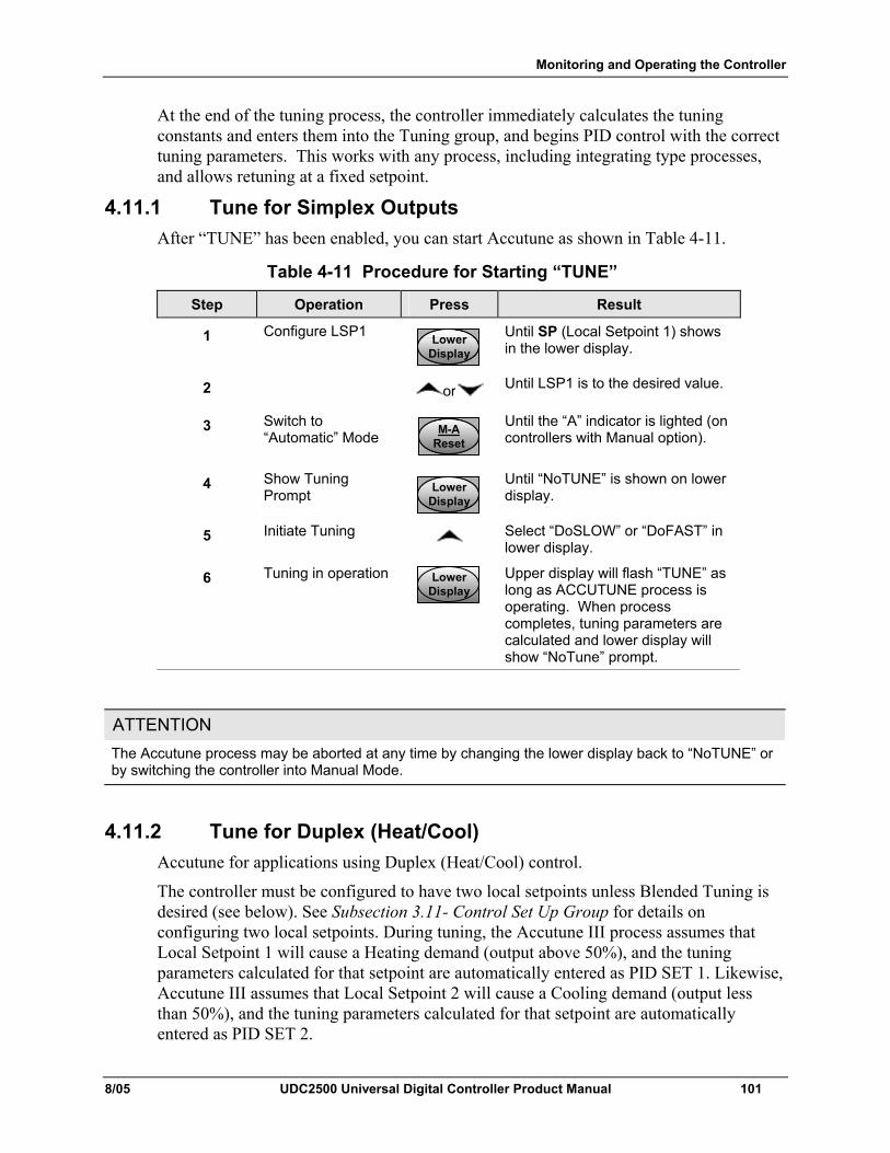
Monitoring and Operating the Controller
8/05 UDC2500 Universal Digital Controller Product Manual 101
At the end of the tuning process, the controller immediately calculates the tuning constants and enters them into the Tuning group, and begins PID control with the correct tuning parameters. This works with any process, including integrating type processes, and allows retuning at a fixed setpoint.
4.11.1 Tune for Simplex Outputs After “TUNE” has been enabled, you can start Accutune as shown in Table 4-11.
Table 4-11 Procedure for Starting “TUNE”
Step Operation Press Result
1 Configure LSP1 LowerDisplayLower
DisplayLower
Display
Until SP (Local Setpoint 1) shows in the lower display.
2 or Until LSP1 is to the desired value.
3 Switch to “Automatic” Mode M-A
ResetM-A
ResetM-A
Reset
Until the “A” indicator is lighted (on controllers with Manual option).
4 Show Tuning Prompt Lower
DisplayLower
DisplayLower
Display
Until “NoTUNE” is shown on lower display.
5 Initiate Tuning Select “DoSLOW” or “DoFAST” in lower display.
6 Tuning in operation LowerDisplayLower
DisplayLower
Display
Upper display will flash “TUNE” as long as ACCUTUNE process is operating. When process completes, tuning parameters are calculated and lower display will show “NoTune” prompt.
ATTENTION The Accutune process may be aborted at any time by changing the lower display back to “NoTUNE” or by switching the controller into Manual Mode.
4.11.2 Tune for Duplex (Heat/Cool) Accutune for applications using Duplex (Heat/Cool) control.
The controller must be configured to have two local setpoints unless Blended Tuning is desired (see below). See Subsection 3.11- Control Set Up Group for details on configuring two local setpoints. During tuning, the Accutune III process assumes that Local Setpoint 1 will cause a Heating demand (output above 50%), and the tuning parameters calculated for that setpoint are automatically entered as PID SET 1. Likewise, Accutune III assumes that Local Setpoint 2 will cause a Cooling demand (output less than 50%), and the tuning parameters calculated for that setpoint are automatically entered as PID SET 2.
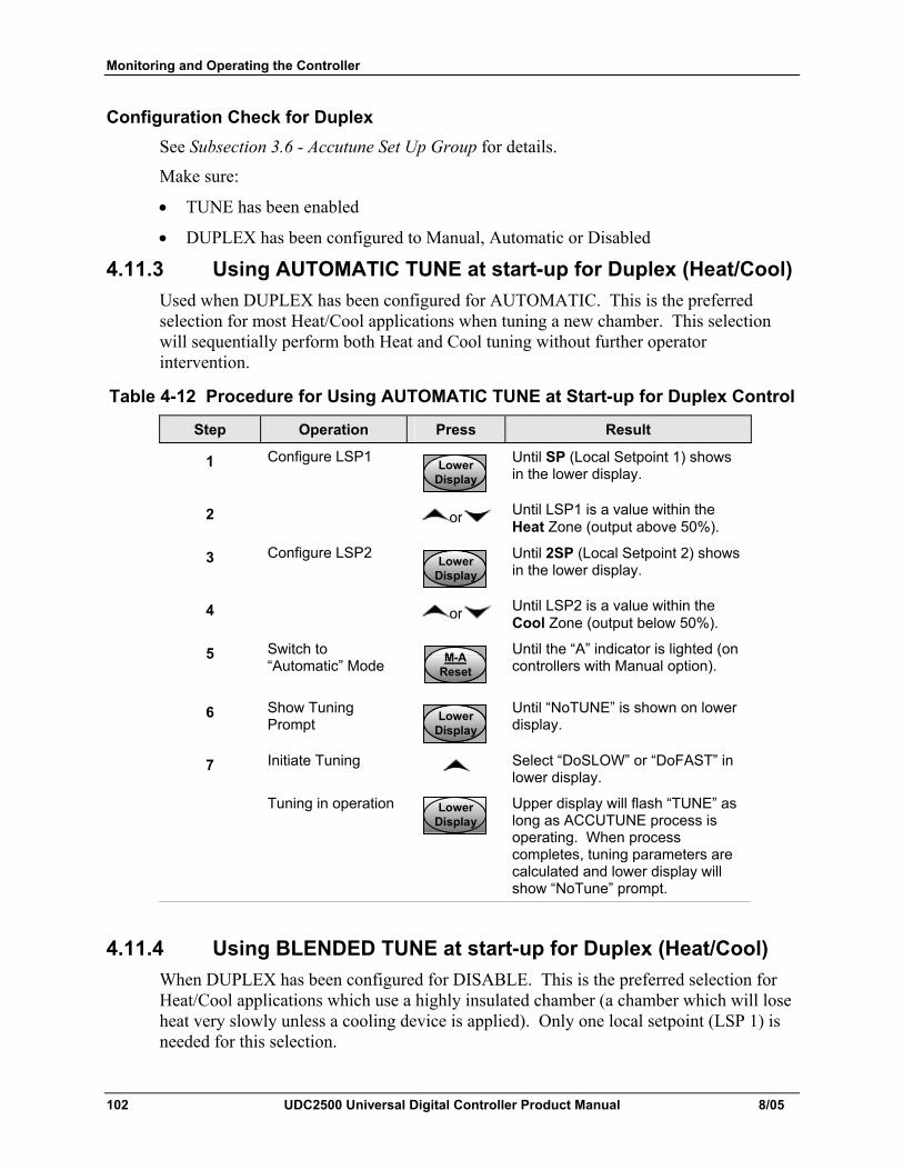
Monitoring and Operating the Controller
102 UDC2500 Universal Digital Controller Product Manual 8/05
Configuration Check for Duplex See Subsection 3.6 - Accutune Set Up Group for details.
Make sure:
• TUNE has been enabled
• DUPLEX has been configured to Manual, Automatic or Disabled
4.11.3 Using AUTOMATIC TUNE at start-up for Duplex (Heat/Cool) Used when DUPLEX has been configured for AUTOMATIC. This is the preferred selection for most Heat/Cool applications when tuning a new chamber. This selection will sequentially perform both Heat and Cool tuning without further operator intervention.
Table 4-12 Procedure for Using AUTOMATIC TUNE at Start-up for Duplex Control
Step Operation Press Result
1 Configure LSP1 LowerDisplayLower
DisplayLower
Display
Until SP (Local Setpoint 1) shows in the lower display.
2 or Until LSP1 is a value within the Heat Zone (output above 50%).
3 Configure LSP2 LowerDisplayLower
DisplayLower
Display
Until 2SP (Local Setpoint 2) shows in the lower display.
4 or Until LSP2 is a value within the Cool Zone (output below 50%).
5 Switch to “Automatic” Mode M-A
ResetM-A
ResetM-A
Reset
Until the “A” indicator is lighted (on controllers with Manual option).
6 Show Tuning Prompt Lower
DisplayLower
DisplayLower
Display
Until “NoTUNE” is shown on lower display.
7 Initiate Tuning Select “DoSLOW” or “DoFAST” in lower display.
Tuning in operation LowerDisplayLower
DisplayLower
Display
Upper display will flash “TUNE” as long as ACCUTUNE process is operating. When process completes, tuning parameters are calculated and lower display will show “NoTune” prompt.
4.11.4 Using BLENDED TUNE at start-up for Duplex (Heat/Cool) When DUPLEX has been configured for DISABLE. This is the preferred selection for Heat/Cool applications which use a highly insulated chamber (a chamber which will lose heat very slowly unless a cooling device is applied). Only one local setpoint (LSP 1) is needed for this selection.
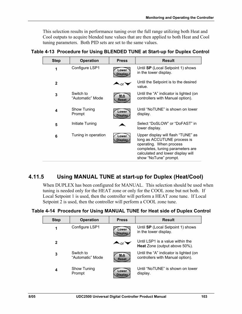
Monitoring and Operating the Controller
8/05 UDC2500 Universal Digital Controller Product Manual 103
This selection results in performance tuning over the full range utilizing both Heat and Cool outputs to acquire blended tune values that are then applied to both Heat and Cool tuning parameters. Both PID sets are set to the same values.
Table 4-13 Procedure for Using BLENDED TUNE at Start-up for Duplex Control
Step Operation Press Result
1 Configure LSP1 LowerDisplayLower
DisplayLower
Display
Until SP (Local Setpoint 1) shows in the lower display.
2 or Until the Setpoint is to the desired value.
3 Switch to “Automatic” Mode M-A
ResetM-A
ResetM-A
Reset
Until the “A” indicator is lighted (on controllers with Manual option).
4 Show Tuning Prompt Lower
DisplayLower
DisplayLower
Display
Until “NoTUNE” is shown on lower display.
5 Initiate Tuning Select “DoSLOW” or “DoFAST” in lower display.
6 Tuning in operation LowerDisplayLower
DisplayLower
Display
Upper display will flash “TUNE” as long as ACCUTUNE process is operating. When process completes, tuning parameters are calculated and lower display will show “NoTune” prompt.
4.11.5 Using MANUAL TUNE at start-up for Duplex (Heat/Cool) When DUPLEX has been configured for MANUAL. This selection should be used when tuning is needed only for the HEAT zone or only for the COOL zone but not both. If Local Setpoint 1 is used, then the controller will perform a HEAT zone tune. If Local Setpoint 2 is used, then the controller will perform a COOL zone tune.
Table 4-14 Procedure for Using MANUAL TUNE for Heat side of Duplex Control
Step Operation Press Result
1 Configure LSP1 LowerDisplayLower
DisplayLower
Display
Until SP (Local Setpoint 1) shows in the lower display.
2 or Until LSP1 is a value within the Heat Zone (output above 50%).
3 Switch to “Automatic” Mode M-A
ResetM-A
ResetM-A
Reset
Until the “A” indicator is lighted (on controllers with Manual option).
4 Show Tuning Prompt Lower
DisplayLower
DisplayLower
Display
Until “NoTUNE” is shown on lower display.

Monitoring and Operating the Controller
104 UDC2500 Universal Digital Controller Product Manual 8/05
Step Operation Press Result
5 Initiate Tuning Select “DoSLOW” or “DoFAST” in lower display.
6 Tuning in operation LowerDisplayLower
DisplayLower
Display
Upper display will flash “TUNE” as long as ACCUTUNE process is operating. When process completes, tuning parameters are calculated and lower display will show “NoTune” prompt.
Table 4-15 Procedure for Using MANUAL TUNE for Cool side of Duplex Control
Step Operation Press Result
1 Configure LSP2 LowerDisplayLower
DisplayLower
Display
Until 2SP (Local Setpoint 2) shows in the lower display.
2 or Until LSP2 is a value within the Cool Zone (output below 50%).
3 Switch to “Automatic” Mode M-A
ResetM-A
ResetM-A
Reset
Until the “A” indicator is lighted (on controllers with Manual option).
4 Show Tuning Prompt Lower
DisplayLower
DisplayLower
Display
Until “NoTUNE” is shown on lower display.
5 Initiate Tuning Select “DoSLOW” or “DoFAST” in lower display.
6 Tuning in operation LowerDisplayLower
DisplayLower
Display
Upper display will flash “TUNE” as long as ACCUTUNE process is operating. When process completes, tuning parameters are calculated and lower display will show “NoTune” prompt.
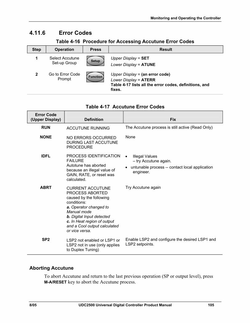
Monitoring and Operating the Controller
8/05 UDC2500 Universal Digital Controller Product Manual 105
4.11.6 Error Codes Table 4-16 Procedure for Accessing Accutune Error Codes
Step Operation Press Result
1 Select Accutune Set-up Group SetupSetup
Upper Display = SET Lower Display = ATUNE
2 Go to Error Code Prompt FunctionFunctionFunction
Upper Display = (an error code) Lower Display = ATERR Table 4-17 lists all the error codes, definitions, and fixes.
Table 4-17 Accutune Error Codes Error Code
(Upper Display)
Definition
Fix
RUN ACCUTUNE RUNNING The Accutune process is still active (Read Only)
NONE NO ERRORS OCCURRED DURING LAST ACCUTUNE PROCEDURE
None
IDFL PROCESS IDENTIFICATION FAILURE Autotune has aborted because an illegal value of GAIN, RATE, or reset was calculated.
• Illegal Values – try Accutune again.
• untunable process -- contact local application engineer.
ABRT CURRENT ACCUTUNE PROCESS ABORTED caused by the following conditions: a. Operator changed to Manual mode b. Digital Input detected c. In Heat region of output and a Cool output calculated or vice versa.
Try Accutune again
SP2 LSP2 not enabled or LSP1 or LSP2 not in use (only applies to Duplex Tuning)
Enable LSP2 and configure the desired LSP1 and LSP2 setpoints.
Aborting Accutune To abort Accutune and return to the last previous operation (SP or output level), press M-A/RESET key to abort the Accutune process.
Monitoring and Operating the Controller
106 UDC2500 Universal Digital Controller Product Manual 8/05
Completing Accutune When Accutune is complete, the calculated tuning parameters are stored in their proper memory location and can be viewed in the TUNING Set up Group, and the controller will control at the local setpoint using these newly calculated tuning constants.
4.12 Fuzzy Overshoot Suppression
Introduction Fuzzy Overshoot Suppression minimizes Process Variable overshoot following a setpoint change or a process disturbance. This is especially useful in processes which experience load changes or where even a small overshoot beyond the setpoint may result in damage or lost product.
How it works The fuzzy logic observes the speed and direction of the PV signal as it approaches the setpoint and temporarily modifies the internal controller response action as necessary to avoid an overshoot. There is no change to the PID algorithm, and the fuzzy logic does not alter the PID tuning parameters. This feature can be independently Enabled or Disabled as required by the application to work with “TUNE” (On-Demand) Accutune III tuning algorithm.
Configuration To configure this item, refer to Section 3 - Configuration:
Set Up Group “ATUNE” Function Prompt “FUZZY” Select “ENAB”(enable) or “DIS” (disable) - Use or .
4.13 Using Two Sets of Tuning Constants
Introduction You can use two sets of tuning constants for single output types and choose the way they are to be switched. (Does not apply for Duplex control.)
The sets can be:
• keyboard selected,
• automatically switched when a predetermined process variable value is reached,
• automatically switched when a predetermined setpoint value is reached.
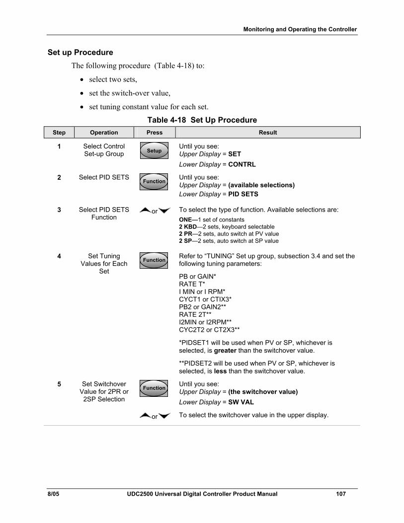
Monitoring and Operating the Controller
8/05 UDC2500 Universal Digital Controller Product Manual 107
Set up Procedure The following procedure (Table 4-18) to:
• select two sets,
• set the switch-over value,
• set tuning constant value for each set.
Table 4-18 Set Up Procedure Step Operation Press Result
1 Select Control Set-up Group SetupSetup
Until you see: Upper Display = SET Lower Display = CONTRL
2 Select PID SETS FunctionFunctionFunction
Until you see: Upper Display = (available selections) Lower Display = PID SETS
3 Select PID SETS Function
or To select the type of function. Available selections are: ONE—1 set of constants 2 KBD—2 sets, keyboard selectable 2 PR—2 sets, auto switch at PV value 2 SP—2 sets, auto switch at SP value
4 Set Tuning Values for Each
Set
FunctionFunctionFunction
Refer to “TUNING” Set up group, subsection 3.4 and set the following tuning parameters:
PB or GAIN* RATE T* I MIN or I RPM* CYCT1 or CTIX3* PB2 or GAIN2** RATE 2T** I2MIN or I2RPM** CYC2T2 or CT2X3**
*PIDSET1 will be used when PV or SP, whichever is selected, is greater than the switchover value.
**PIDSET2 will be used when PV or SP, whichever is selected, is less than the switchover value.
5 Set Switchover Value for 2PR or
2SP Selection
FunctionFunctionFunction
Until you see: Upper Display = (the switchover value) Lower Display = SW VAL
or To select the switchover value in the upper display.
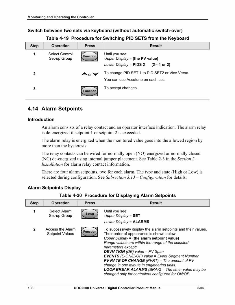
Monitoring and Operating the Controller
108 UDC2500 Universal Digital Controller Product Manual 8/05
Switch between two sets via keyboard (without automatic switch-over) Table 4-19 Procedure for Switching PID SETS from the Keyboard
Step Operation Press Result
1 Select Control Set-up Group FunctionFunctionFunction
Until you see: Upper Display = (the PV value) Lower Display = PIDS X (X= 1 or 2)
2 or To change PID SET 1 to PID SET2 or Vice Versa.
You can use Accutune on each set.
3 FunctionFunctionFunction
To accept changes.
4.14 Alarm Setpoints
Introduction An alarm consists of a relay contact and an operator interface indication. The alarm relay is de-energized if setpoint 1 or setpoint 2 is exceeded.
The alarm relay is energized when the monitored value goes into the allowed region by more than the hysteresis.
The relay contacts can be wired for normally open (NO) energized or normally closed (NC) de-energized using internal jumper placement. See Table 2-3 in the Section 2 – Installation for alarm relay contact information.
There are four alarm setpoints, two for each alarm. The type and state (High or Low) is selected during configuration. See Subsection 3.13 – Configuration for details.
Alarm Setpoints Display Table 4-20 Procedure for Displaying Alarm Setpoints
Step Operation Press Result
1 Select Alarm Set-up Group SetupSetup
Until you see: Upper Display = SET Lower Display = ALARMS
2 Access the Alarm Setpoint Values FunctionFunctionFunction
To successively display the alarm setpoints and their values. Their order of appearance is shown below. Upper Display = (the alarm setpoint value) Range values are within the range of the selected parameters except: DEVIATION (DE) value = PV Span EVENTS (E-ON/E-OF) value = Event Segment Number PV RATE OF CHANGE (PVRT) = The amount of PV change in one minute in engineering units. LOOP BREAK ALARMS (BRAK) = The timer value may be changed only for controllers configured for ON/OF.
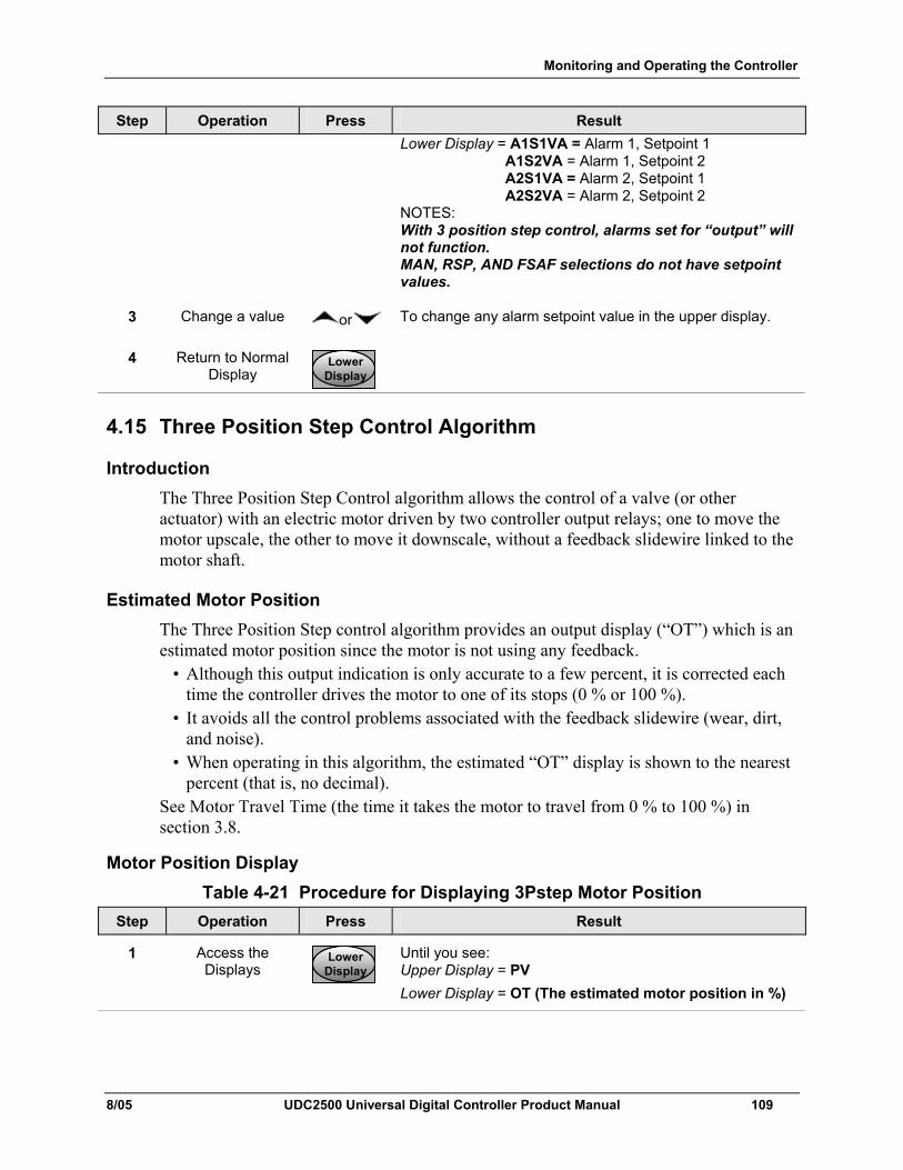
Monitoring and Operating the Controller
8/05 UDC2500 Universal Digital Controller Product Manual 109
Step Operation Press Result Lower Display = A1S1VA = Alarm 1, Setpoint 1 A1S2VA = Alarm 1, Setpoint 2 A2S1VA = Alarm 2, Setpoint 1 A2S2VA = Alarm 2, Setpoint 2 NOTES: With 3 position step control, alarms set for “output” will not function. MAN, RSP, AND FSAF selections do not have setpoint values.
3 Change a value or To change any alarm setpoint value in the upper display.
4 Return to Normal Display
LowerDisplayLower
DisplayLower
Display
4.15 Three Position Step Control Algorithm
Introduction The Three Position Step Control algorithm allows the control of a valve (or other actuator) with an electric motor driven by two controller output relays; one to move the motor upscale, the other to move it downscale, without a feedback slidewire linked to the motor shaft.
Estimated Motor Position The Three Position Step control algorithm provides an output display (“OT”) which is an estimated motor position since the motor is not using any feedback.
• Although this output indication is only accurate to a few percent, it is corrected each time the controller drives the motor to one of its stops (0 % or 100 %).
• It avoids all the control problems associated with the feedback slidewire (wear, dirt, and noise).
• When operating in this algorithm, the estimated “OT” display is shown to the nearest percent (that is, no decimal).
See Motor Travel Time (the time it takes the motor to travel from 0 % to 100 %) in section 3.8.
Motor Position Display Table 4-21 Procedure for Displaying 3Pstep Motor Position
Step Operation Press Result
1 Access the Displays
LowerDisplayLower
DisplayLower
Display
Until you see: Upper Display = PV Lower Display = OT (The estimated motor position in %)
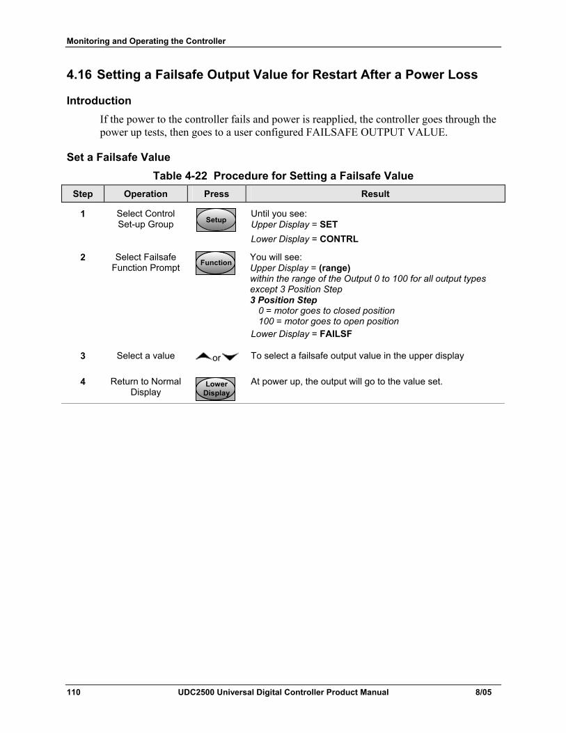
Monitoring and Operating the Controller
110 UDC2500 Universal Digital Controller Product Manual 8/05
4.16 Setting a Failsafe Output Value for Restart After a Power Loss
Introduction If the power to the controller fails and power is reapplied, the controller goes through the power up tests, then goes to a user configured FAILSAFE OUTPUT VALUE.
Set a Failsafe Value Table 4-22 Procedure for Setting a Failsafe Value
Step Operation Press Result
1 Select Control Set-up Group SetupSetup
Until you see: Upper Display = SET Lower Display = CONTRL
2 Select Failsafe Function Prompt FunctionFunctionFunction
You will see: Upper Display = (range) within the range of the Output 0 to 100 for all output types except 3 Position Step 3 Position Step 0 = motor goes to closed position 100 = motor goes to open position Lower Display = FAILSF
3 Select a value or To select a failsafe output value in the upper display
4 Return to Normal Display
LowerDisplayLower
DisplayLower
Display
At power up, the output will go to the value set.
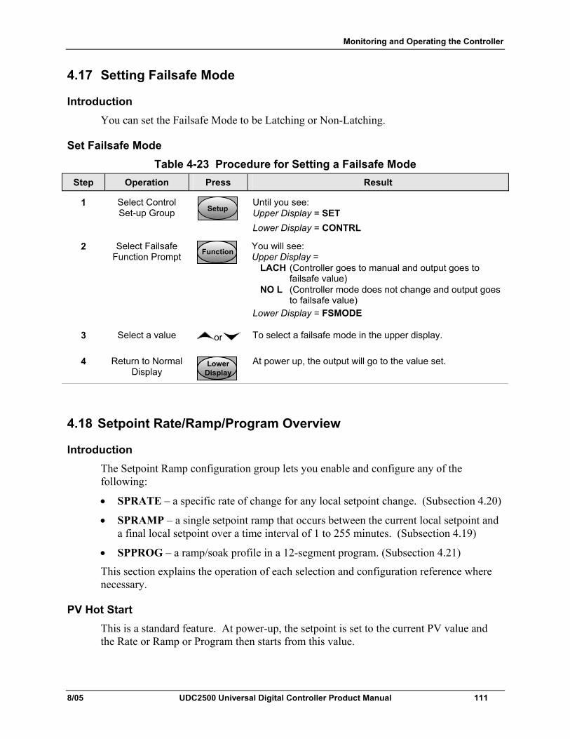
Monitoring and Operating the Controller
8/05 UDC2500 Universal Digital Controller Product Manual 111
4.17 Setting Failsafe Mode
Introduction You can set the Failsafe Mode to be Latching or Non-Latching.
Set Failsafe Mode Table 4-23 Procedure for Setting a Failsafe Mode
Step Operation Press Result
1 Select Control Set-up Group SetupSetup
Until you see: Upper Display = SET Lower Display = CONTRL
2 Select Failsafe Function Prompt FunctionFunctionFunction
You will see: Upper Display = LACH (Controller goes to manual and output goes to failsafe value) NO L (Controller mode does not change and output goes to failsafe value) Lower Display = FSMODE
3 Select a value or To select a failsafe mode in the upper display.
4 Return to Normal Display
LowerDisplayLower
DisplayLower
Display
At power up, the output will go to the value set.
4.18 Setpoint Rate/Ramp/Program Overview
Introduction The Setpoint Ramp configuration group lets you enable and configure any of the following:
• SPRATE – a specific rate of change for any local setpoint change. (Subsection 4.20)
• SPRAMP – a single setpoint ramp that occurs between the current local setpoint and a final local setpoint over a time interval of 1 to 255 minutes. (Subsection 4.19)
• SPPROG – a ramp/soak profile in a 12-segment program. (Subsection 4.21)
This section explains the operation of each selection and configuration reference where necessary.
PV Hot Start This is a standard feature. At power-up, the setpoint is set to the current PV value and the Rate or Ramp or Program then starts from this value.
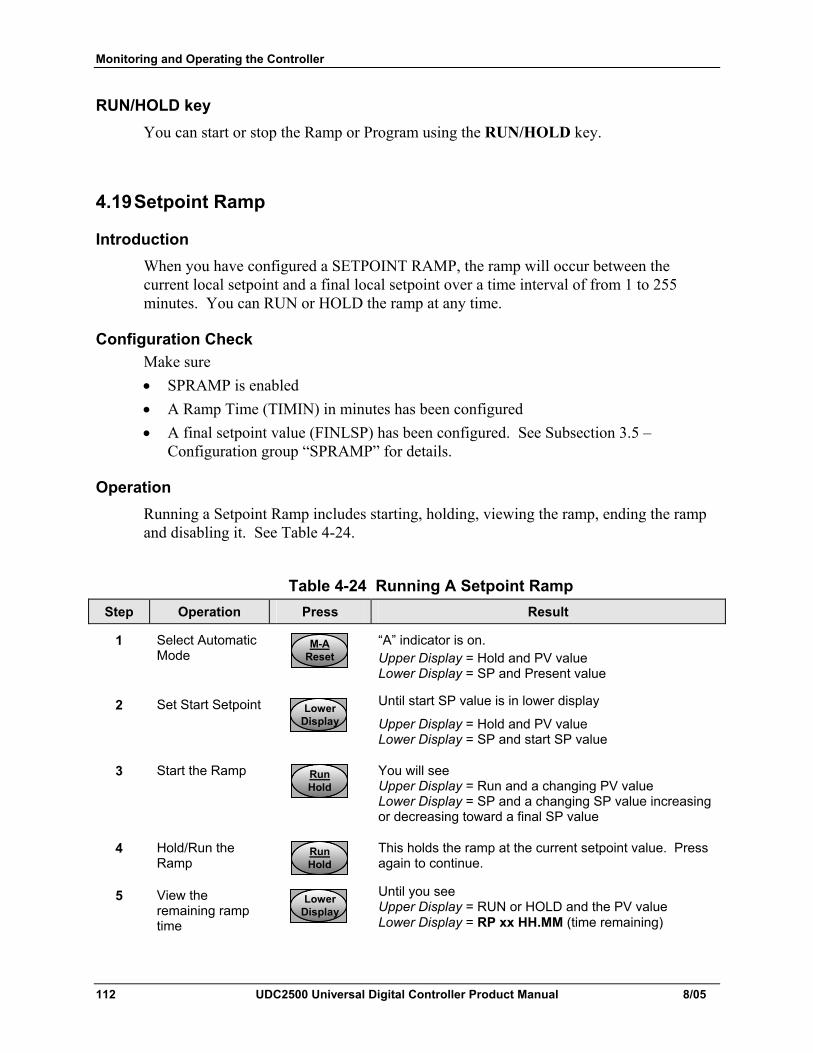
Monitoring and Operating the Controller
112 UDC2500 Universal Digital Controller Product Manual 8/05
RUN/HOLD key You can start or stop the Ramp or Program using the RUN/HOLD key.
4.19 Setpoint Ramp
Introduction When you have configured a SETPOINT RAMP, the ramp will occur between the current local setpoint and a final local setpoint over a time interval of from 1 to 255 minutes. You can RUN or HOLD the ramp at any time.
Configuration Check Make sure • SPRAMP is enabled • A Ramp Time (TIMIN) in minutes has been configured • A final setpoint value (FINLSP) has been configured. See Subsection 3.5 –
Configuration group “SPRAMP” for details.
Operation Running a Setpoint Ramp includes starting, holding, viewing the ramp, ending the ramp and disabling it. See Table 4-24.
Table 4-24 Running A Setpoint Ramp
Step Operation Press Result
1 Select Automatic Mode
M-AResetM-A
ResetM-A
Reset
“A” indicator is on. Upper Display = Hold and PV value Lower Display = SP and Present value
2 Set Start Setpoint LowerDisplayLower
DisplayLower
Display
Until start SP value is in lower display
Upper Display = Hold and PV value Lower Display = SP and start SP value
3 Start the Ramp RunHoldRunHoldRunHold
You will see Upper Display = Run and a changing PV value Lower Display = SP and a changing SP value increasing or decreasing toward a final SP value
4 Hold/Run the Ramp
RunHoldRunHoldRunHold
This holds the ramp at the current setpoint value. Press again to continue.
5 View the remaining ramp time
LowerDisplayLower
DisplayLower
Display
Until you see Upper Display = RUN or HOLD and the PV value Lower Display = RP xx HH.MM (time remaining)
Monitoring and Operating the Controller
8/05 UDC2500 Universal Digital Controller Product Manual 113
Step Operation Press Result
6 End the Ramp When the final setpoint is reached, “RUN” changes to “HOLD” in the upper display and the controller operates at the new final setpoint.
7 Disable SPRAMP See Section 3 – Configuration group “SPRAMP” for details.
Power Outage If power is lost during a ramp, upon power-up the controller will be in HOLD and the setpoint value will be the setpoint value prior to the beginning of the setpoint ramp.
The ramp is placed in hold at the beginning.
Configure the mode at Set Up Group “CONTROL”, function prompt “PWRUP”. See Subsection 3.11 – CONTRL GROUP FUNCTION Prompts.
4.20 Setpoint Rate
Introduction When you have configured a SETPOINT RATE, it will apply immediately to local setpoint change.
Configuration check Make sure:
• SPRATE is enabled • SP RATE and SPPROG are not running.
• A Rate Up (EUHRUP) or Rate Down (EUHRDN) value has been configured in Engineering units per hour.
ATTENTION A value of 0 will imply an immediate change in setpoint, that is, NO RATE applies. See Subsection 3.5 – Configuration group “SPRAMP” for details.)
Operation When a change to local setpoint is made, this controller will ramp from the original setpoint to the “target” setpoint at the rate specified.
The current setpoint value can be viewed at Sn on the lower display.
Power outages If power is lost before the “target” setpoint is reached, upon power recovery, the controller powers up with Sn = Current PV value and it automatically “Restarts” from Sn = current PV value up to the original “target” setpoint.
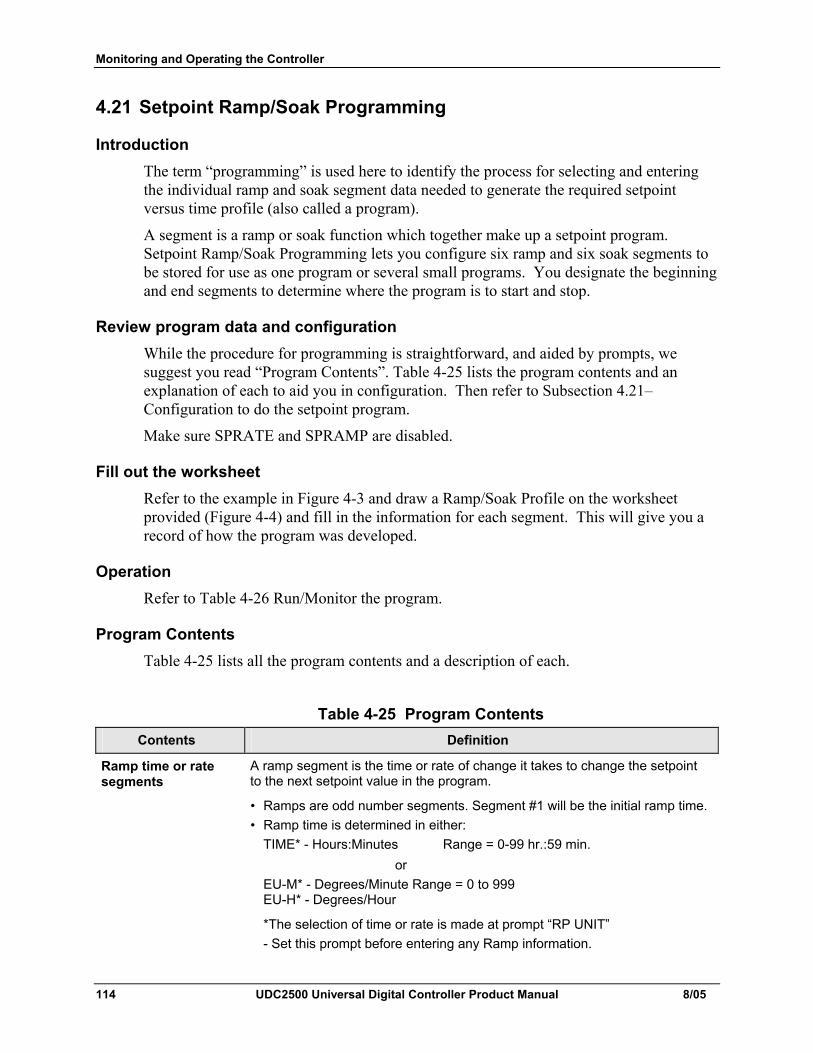
Monitoring and Operating the Controller
114 UDC2500 Universal Digital Controller Product Manual 8/05
4.21 Setpoint Ramp/Soak Programming
Introduction The term “programming” is used here to identify the process for selecting and entering the individual ramp and soak segment data needed to generate the required setpoint versus time profile (also called a program).
A segment is a ramp or soak function which together make up a setpoint program. Setpoint Ramp/Soak Programming lets you configure six ramp and six soak segments to be stored for use as one program or several small programs. You designate the beginning and end segments to determine where the program is to start and stop.
Review program data and configuration While the procedure for programming is straightforward, and aided by prompts, we suggest you read “Program Contents”. Table 4-25 lists the program contents and an explanation of each to aid you in configuration. Then refer to Subsection 4.21– Configuration to do the setpoint program.
Make sure SPRATE and SPRAMP are disabled.
Fill out the worksheet Refer to the example in Figure 4-3 and draw a Ramp/Soak Profile on the worksheet provided (Figure 4-4) and fill in the information for each segment. This will give you a record of how the program was developed.
Operation Refer to Table 4-26 Run/Monitor the program.
Program Contents Table 4-25 lists all the program contents and a description of each.
Table 4-25 Program Contents Contents Definition
Ramp time or rate segments
A ramp segment is the time or rate of change it takes to change the setpoint to the next setpoint value in the program.
• Ramps are odd number segments. Segment #1 will be the initial ramp time. • Ramp time is determined in either: TIME* - Hours:Minutes Range = 0-99 hr.:59 min. or EU-M* - Degrees/Minute Range = 0 to 999 EU-H* - Degrees/Hour
*The selection of time or rate is made at prompt “RP UNIT” - Set this prompt before entering any Ramp information.
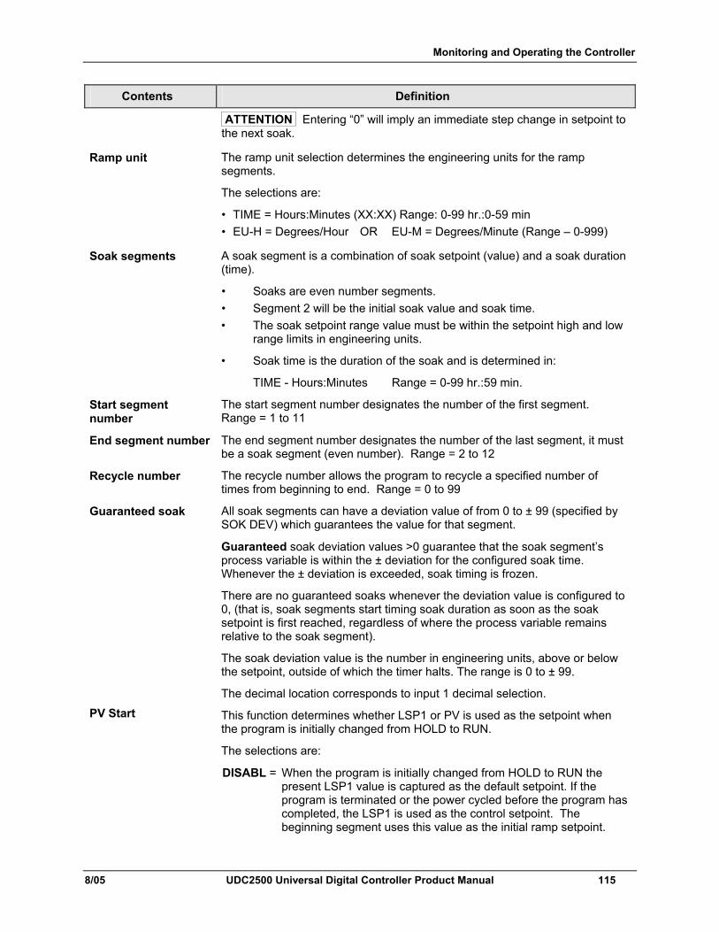
Monitoring and Operating the Controller
8/05 UDC2500 Universal Digital Controller Product Manual 115
Contents Definition
ATTENTION Entering “0” will imply an immediate step change in setpoint to the next soak.
Ramp unit The ramp unit selection determines the engineering units for the ramp segments.
The selections are:
• TIME = Hours:Minutes (XX:XX) Range: 0-99 hr.:0-59 min • EU-H = Degrees/Hour OR EU-M = Degrees/Minute (Range – 0-999)
Soak segments A soak segment is a combination of soak setpoint (value) and a soak duration (time).
• Soaks are even number segments. • Segment 2 will be the initial soak value and soak time. • The soak setpoint range value must be within the setpoint high and low range limits in engineering units.
• Soak time is the duration of the soak and is determined in:
TIME - Hours:Minutes Range = 0-99 hr.:59 min.
Start segment number
The start segment number designates the number of the first segment. Range = 1 to 11
End segment number The end segment number designates the number of the last segment, it must be a soak segment (even number). Range = 2 to 12
Recycle number The recycle number allows the program to recycle a specified number of times from beginning to end. Range = 0 to 99
Guaranteed soak All soak segments can have a deviation value of from 0 to ± 99 (specified by SOK DEV) which guarantees the value for that segment.
Guaranteed soak deviation values >0 guarantee that the soak segment’s process variable is within the ± deviation for the configured soak time. Whenever the ± deviation is exceeded, soak timing is frozen.
There are no guaranteed soaks whenever the deviation value is configured to 0, (that is, soak segments start timing soak duration as soon as the soak setpoint is first reached, regardless of where the process variable remains relative to the soak segment).
The soak deviation value is the number in engineering units, above or below the setpoint, outside of which the timer halts. The range is 0 to ± 99.
The decimal location corresponds to input 1 decimal selection.
PV Start This function determines whether LSP1 or PV is used as the setpoint when the program is initially changed from HOLD to RUN.
The selections are:
DISABL = When the program is initially changed from HOLD to RUN the present LSP1 value is captured as the default setpoint. If the program is terminated or the power cycled before the program has completed, the LSP1 is used as the control setpoint. The beginning segment uses this value as the initial ramp setpoint.
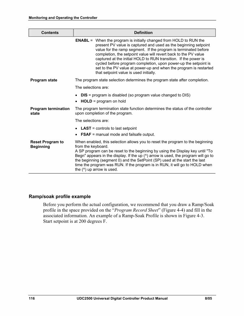
Monitoring and Operating the Controller
116 UDC2500 Universal Digital Controller Product Manual 8/05
Contents Definition
ENABL = When the program is initially changed from HOLD to RUN the present PV value is captured and used as the beginning setpoint value for the ramp segment. If the program is terminated before completion, the setpoint value will revert back to the PV value captured at the initial HOLD to RUN transition. If the power is cycled before program completion, upon power-up the setpoint is set to the PV value at power-up and when the program is restarted that setpoint value is used initially.
Program state The program state selection determines the program state after completion.
The selections are:
• DIS = program is disabled (so program value changed to DIS) • HOLD = program on hold
Program termination state
The program termination state function determines the status of the controller upon completion of the program.
The selections are:
• LAST = controls to last setpoint • FSAF = manual mode and failsafe output.
Reset Program to Beginning
When enabled, this selection allows you to reset the program to the beginning from the keyboard. A SP program can be reset to the beginning by using the Display key until "To Begn" appears in the display. If the up (^) arrow is used, the program will go to the beginning (segment 0) and the SetPoint (SP) used at the start the last time the program was RUN. If the program is in RUN, it will go to HOLD when the (^) up arrow is used.
Ramp/soak profile example Before you perform the actual configuration, we recommend that you draw a Ramp/Soak profile in the space provided on the “Program Record Sheet” (Figure 4-4) and fill in the associated information. An example of a Ramp-Soak Profile is shown in Figure 4-3. Start setpoint is at 200 degrees F.
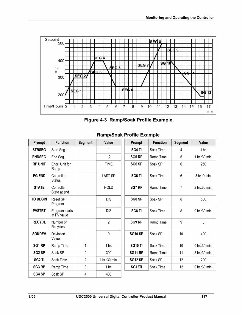
Monitoring and Operating the Controller
8/05 UDC2500 Universal Digital Controller Product Manual 117
500
400
200
300
°F
Time/Hours 0 1 2 3 4 5 6 7 8 9 10 11 12 13 14 15 16 17
SEG 2SEG 3
SEG 4
SEG 5
SEG 6
SEG 7
SEG 8
SEG 9
SG 10
SG 11
SG 12SEG 1
F
20765
Setpoint
Figure 4-3 Ramp/Soak Profile Example
Ramp/Soak Profile Example Prompt Function Segment Value Prompt Function Segment Value
STRSEG Start Seg. 1 SG4 TI Soak Time 4 1 hr.
ENDSEG End Seg. 12 SG5 RP Ramp Time 5 1 hr.:30 min.
RP UNIT Engr. Unit for Ramp
TIME SG6 SP Soak SP 6 250
PG END Controller Status
LAST SP SG6 TI Soak Time 6 3 hr.:0 min.
STATE Controller State at end
HOLD SG7 RP Ramp Time 7 2 hr.:30 min.
TO BEGIN Reset SP Program
DIS SG8 SP Soak SP 8 500
PVSTRT Program starts at PV value
DIS SG8 TI Soak Time 8 0 hr.:30 min.
RECYCL Number of Recycles
2 SG9 RP Ramp Time 9 0
SOKDEV Deviation Value
0 SG10 SP Soak SP 10 400
SG1 RP Ramp Time 1 1 hr. SG10 TI Soak Time 10 0 hr.:30 min.
SG2 SP Soak SP 2 300 SG11 RP Ramp Time 11 3 hr.:30 min.
SG2 TI Soak Time 2 1 hr.:30 min. SG12 SP Soak SP 12 200
SG3 RP Ramp Time 3 1 hr. SG12TI Soak Time 12 0 hr.:30 min.
SG4 SP Soak SP 4 400
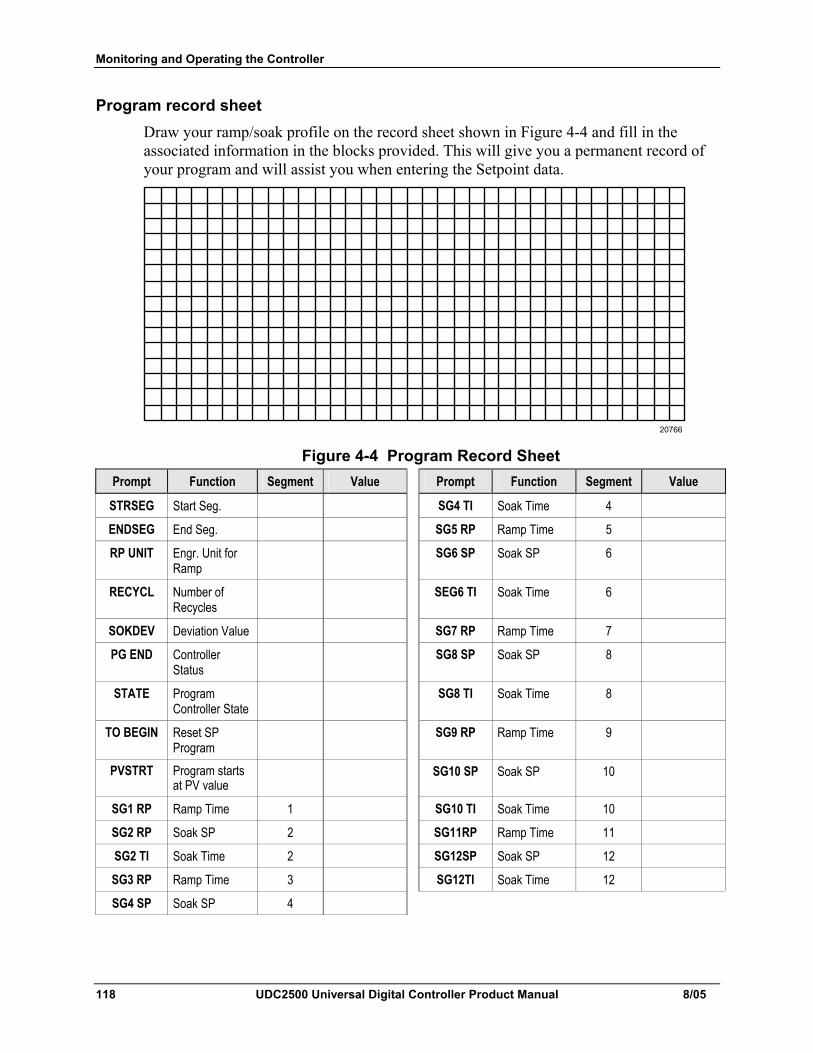
Monitoring and Operating the Controller
118 UDC2500 Universal Digital Controller Product Manual 8/05
Program record sheet Draw your ramp/soak profile on the record sheet shown in Figure 4-4 and fill in the associated information in the blocks provided. This will give you a permanent record of your program and will assist you when entering the Setpoint data.
20766 Figure 4-4 Program Record Sheet
Prompt Function Segment Value Prompt Function Segment Value
STRSEG Start Seg. SG4 TI Soak Time 4
ENDSEG End Seg. SG5 RP Ramp Time 5
RP UNIT Engr. Unit for Ramp
SG6 SP Soak SP 6
RECYCL Number of Recycles
SEG6 TI Soak Time 6
SOKDEV Deviation Value SG7 RP Ramp Time 7
PG END Controller Status
SG8 SP Soak SP 8
STATE Program Controller State
SG8 TI Soak Time 8
TO BEGIN Reset SP Program
SG9 RP Ramp Time 9
PVSTRT Program starts at PV value
SG10 SP Soak SP 10
SG1 RP Ramp Time 1 SG10 TI Soak Time 10
SG2 RP Soak SP 2 SG11RP Ramp Time 11
SG2 TI Soak Time 2 SG12SP Soak SP 12
SG3 RP Ramp Time 3 SG12TI Soak Time 12
SG4 SP Soak SP 4
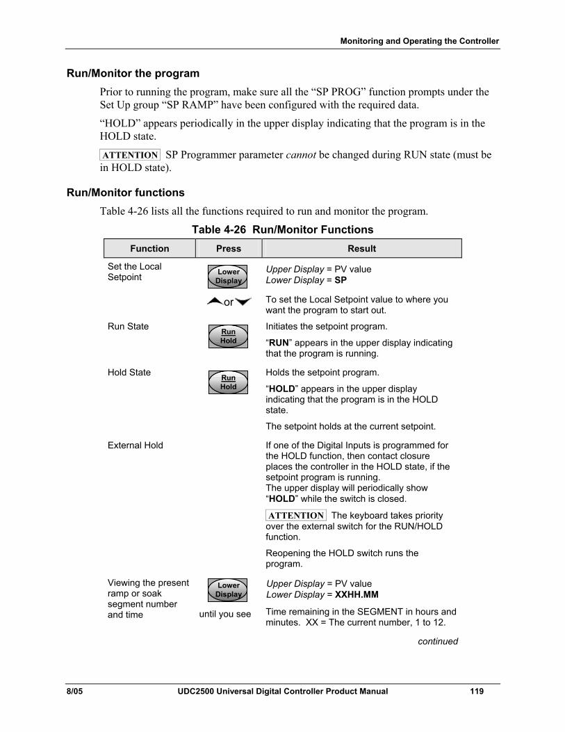
Monitoring and Operating the Controller
8/05 UDC2500 Universal Digital Controller Product Manual 119
Run/Monitor the program Prior to running the program, make sure all the “SP PROG” function prompts under the Set Up group “SP RAMP” have been configured with the required data.
“HOLD” appears periodically in the upper display indicating that the program is in the HOLD state.
ATTENTION SP Programmer parameter cannot be changed during RUN state (must be in HOLD state).
Run/Monitor functions Table 4-26 lists all the functions required to run and monitor the program.
Table 4-26 Run/Monitor Functions Function Press Result
Set the Local Setpoint Lower
DisplayLower
DisplayLower
Display
Upper Display = PV value Lower Display = SP
or To set the Local Setpoint value to where you want the program to start out.
Run State RunHoldRunHoldRunHold
Initiates the setpoint program.
“RUN” appears in the upper display indicating that the program is running.
Hold State RunHoldRunHoldRunHold
Holds the setpoint program.
“HOLD” appears in the upper display indicating that the program is in the HOLD state.
The setpoint holds at the current setpoint.
External Hold If one of the Digital Inputs is programmed for the HOLD function, then contact closure places the controller in the HOLD state, if the setpoint program is running. The upper display will periodically show “HOLD” while the switch is closed.
ATTENTION The keyboard takes priority over the external switch for the RUN/HOLD function.
Reopening the HOLD switch runs the program.
Viewing the present ramp or soak segment number and time
LowerDisplayLower
DisplayLower
Display until you see
Upper Display = PV value Lower Display = XXHH.MM
Time remaining in the SEGMENT in hours and minutes. XX = The current number, 1 to 12.
continued
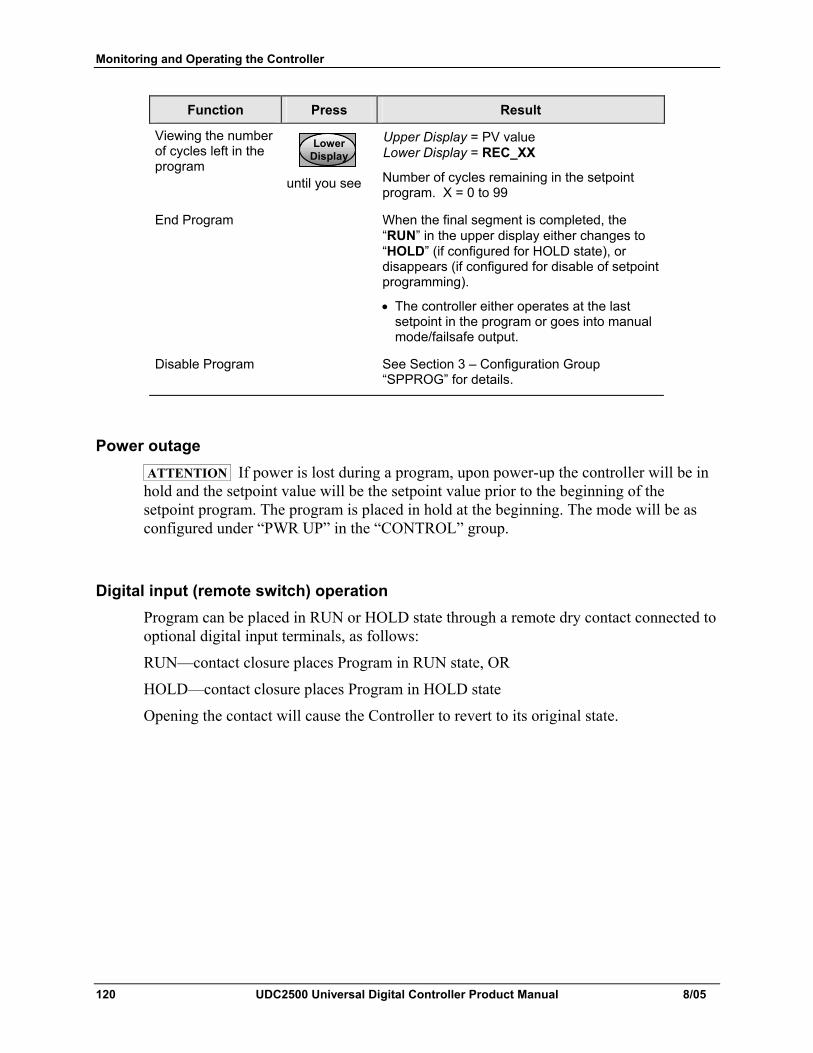
Monitoring and Operating the Controller
120 UDC2500 Universal Digital Controller Product Manual 8/05
Function Press Result
Viewing the number of cycles left in the program
LowerDisplayLower
DisplayLower
Display until you see
Upper Display = PV value Lower Display = REC_XX
Number of cycles remaining in the setpoint program. X = 0 to 99
End Program When the final segment is completed, the “RUN” in the upper display either changes to “HOLD” (if configured for HOLD state), or disappears (if configured for disable of setpoint programming).
• The controller either operates at the last setpoint in the program or goes into manual mode/failsafe output.
Disable Program See Section 3 – Configuration Group “SPPROG” for details.
Power outage ATTENTION If power is lost during a program, upon power-up the controller will be in hold and the setpoint value will be the setpoint value prior to the beginning of the setpoint program. The program is placed in hold at the beginning. The mode will be as configured under “PWR UP” in the “CONTROL” group.
Digital input (remote switch) operation Program can be placed in RUN or HOLD state through a remote dry contact connected to optional digital input terminals, as follows:
RUN—contact closure places Program in RUN state, OR
HOLD—contact closure places Program in HOLD state
Opening the contact will cause the Controller to revert to its original state.
Input Calibration
8/05 UDC2500 Universal Digital Controller Product Manual 121
5 Input Calibration
WARNING—SHOCK HAZARD INPUT CALIBRATION MAY REQUIRE ACCESS TO HAZARDOUS LIVE CIRCUITS, AND SHOULD ONLY BE PERFORMED BY QUALIFIED SERVICE PERSONNEL. MORE THAN ONE SWITCH MAY BE REQUIRED TO DE-ENERGIZE UNIT BEFORE CALIBRATION.
5.1 Overview
Introduction This section describes the field calibration procedures for Input 1 and Input 2.
• All input actuations in every UDC2500 controller are fully factory-calibrated and are ready for configuration by the user.
• Field Calibration can improve the accuracy of the Controller if necessary for a particular application.
CAUTION The field calibration will be lost if a change in input type configuration is implemented at a later time. The original factory calibration data remains available for later use after a field calibration is done. See subsection 0 if you want to restore factory calibration values.
What's in this section? The following topics are covered in this section.
TOPIC See Page
5.1 Overview 121
5.2 Minimum and Maximum Range Values 122
5.3 Preliminary Information 124
5.4 Input #1 Set Up Wiring 125
5.5 Input #1 Calibration Procedure 129
5.6 Input #2 Set Up Wiring 131
5.7 Input #2 Calibration Procedure 132
0 Restore Factory Calibration 134
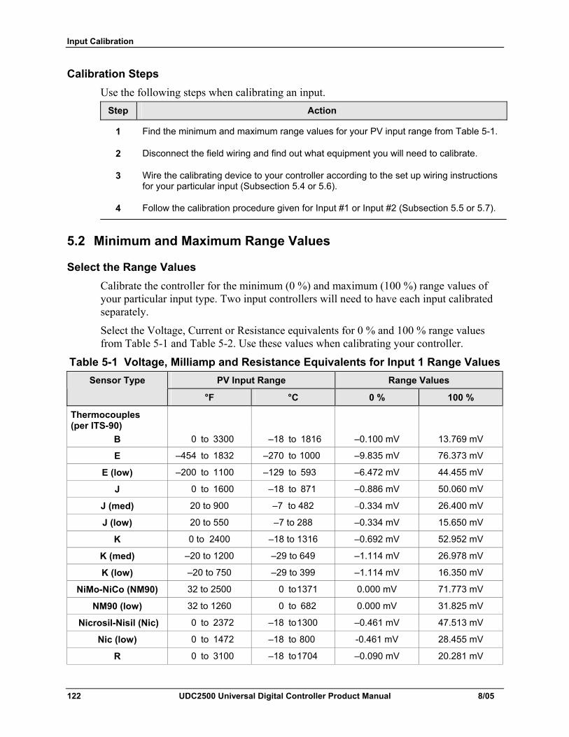
Input Calibration
122 UDC2500 Universal Digital Controller Product Manual 8/05
Calibration Steps Use the following steps when calibrating an input.
Step Action
1 Find the minimum and maximum range values for your PV input range from Table 5-1.
2 Disconnect the field wiring and find out what equipment you will need to calibrate.
3 Wire the calibrating device to your controller according to the set up wiring instructions for your particular input (Subsection 5.4 or 5.6).
4 Follow the calibration procedure given for Input #1 or Input #2 (Subsection 5.5 or 5.7).
5.2 Minimum and Maximum Range Values
Select the Range Values Calibrate the controller for the minimum (0 %) and maximum (100 %) range values of your particular input type. Two input controllers will need to have each input calibrated separately.
Select the Voltage, Current or Resistance equivalents for 0 % and 100 % range values from Table 5-1 and Table 5-2. Use these values when calibrating your controller.
Table 5-1 Voltage, Milliamp and Resistance Equivalents for Input 1 Range Values PV Input Range Range Values Sensor Type
°F °C 0 % 100 %
Thermocouples (per ITS-90)
B 0 to 3300 –18 to 1816 –0.100 mV 13.769 mV
E –454 to 1832 –270 to 1000 –9.835 mV 76.373 mV
E (low) –200 to 1100 –129 to 593 –6.472 mV 44.455 mV
J 0 to 1600 –18 to 871 –0.886 mV 50.060 mV
J (med) 20 to 900 –7 to 482 –0.334 mV 26.400 mV
J (low) 20 to 550 –7 to 288 –0.334 mV 15.650 mV
K 0 to 2400 –18 to 1316 –0.692 mV 52.952 mV
K (med) –20 to 1200 –29 to 649 –1.114 mV 26.978 mV
K (low) –20 to 750 –29 to 399 –1.114 mV 16.350 mV
NiMo-NiCo (NM90) 32 to 2500 0 to 1371 0.000 mV 71.773 mV
NM90 (low) 32 to 1260 0 to 682 0.000 mV 31.825 mV
Nicrosil-Nisil (Nic) 0 to 2372 –18 to 1300 –0.461 mV 47.513 mV
Nic (low) 0 to 1472 –18 to 800 -0.461 mV 28.455 mV
R 0 to 3100 –18 to 1704 –0.090 mV 20.281 mV
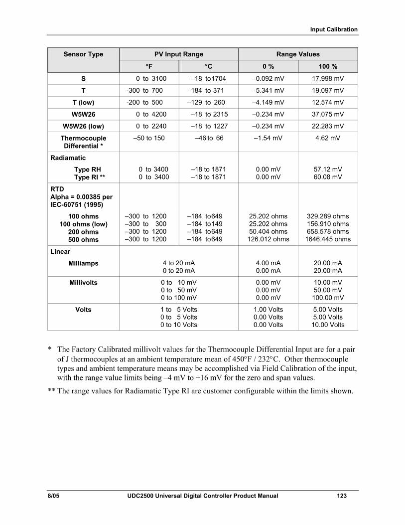
Input Calibration
8/05 UDC2500 Universal Digital Controller Product Manual 123
PV Input Range Range Values Sensor Type
°F °C 0 % 100 %
S 0 to 3100 –18 to 1704 –0.092 mV 17.998 mV
T -300 to 700 –184 to 371 –5.341 mV 19.097 mV
T (low) -200 to 500 –129 to 260 –4.149 mV 12.574 mV
W5W26 0 to 4200 –18 to 2315 –0.234 mV 37.075 mV
W5W26 (low) 0 to 2240 –18 to 1227 –0.234 mV 22.283 mV
Thermocouple Differential *
–50 to 150 –46 to 66 –1.54 mV 4.62 mV
Radiamatic
Type RH Type RI **
0 to 3400 0 to 3400
–18 to 1871 –18 to 1871
0.00 mV 0.00 mV
57.12 mV 60.08 mV
RTD Alpha = 0.00385 per IEC-60751 (1995)
100 ohms 100 ohms (low)
200 ohms 500 ohms
–300 to 1200 –300 to 300 –300 to 1200 –300 to 1200
–184 to 649 –184 to 149 –184 to 649 –184 to 649
25.202 ohms 25.202 ohms 50.404 ohms 126.012 ohms
329.289 ohms 156.910 ohms 658.578 ohms
1646.445 ohms
Linear
Milliamps
4 to 20 mA 0 to 20 mA
4.00 mA 0.00 mA
20.00 mA 20.00 mA
Millivolts 0 to 10 mV 0 to 50 mV 0 to 100 mV
0.00 mV 0.00 mV 0.00 mV
10.00 mV 50.00 mV 100.00 mV
Volts 1 to 5 Volts 0 to 5 Volts 0 to 10 Volts
1.00 Volts 0.00 Volts 0.00 Volts
5.00 Volts 5.00 Volts 10.00 Volts
* The Factory Calibrated millivolt values for the Thermocouple Differential Input are for a pair of J thermocouples at an ambient temperature mean of 450°F / 232°C. Other thermocouple types and ambient temperature means may be accomplished via Field Calibration of the input, with the range value limits being –4 mV to +16 mV for the zero and span values.
** The range values for Radiamatic Type RI are customer configurable within the limits shown.
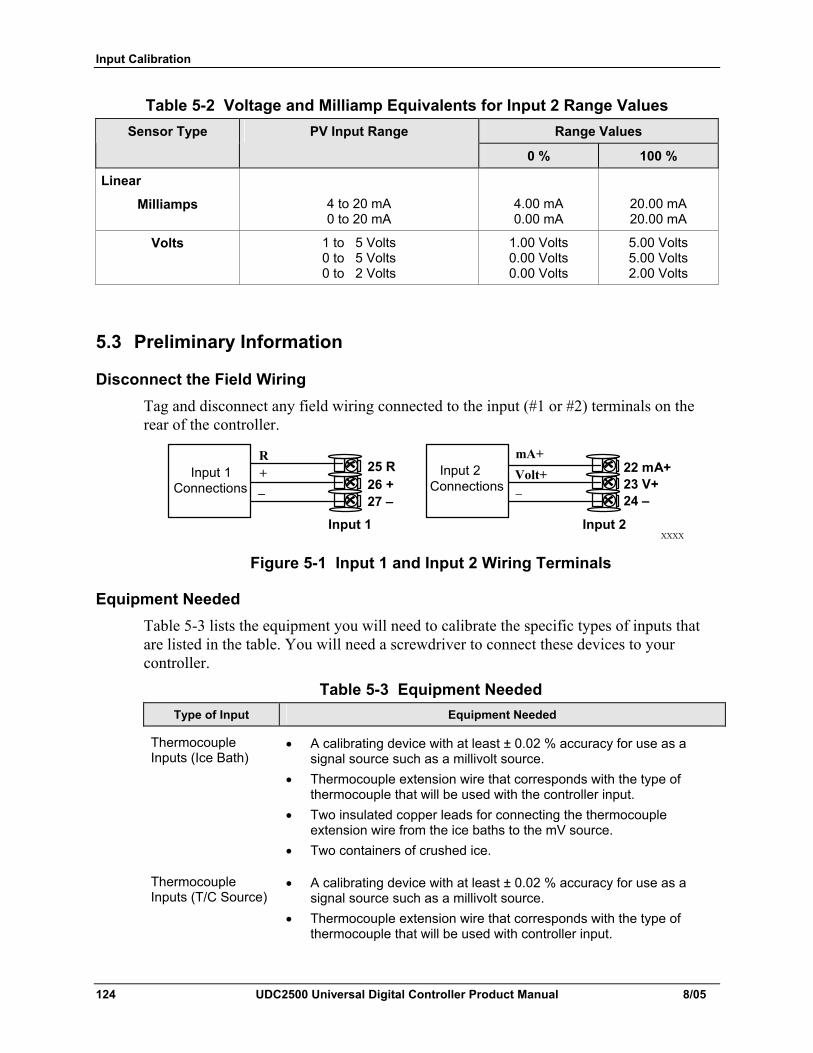
Input Calibration
124 UDC2500 Universal Digital Controller Product Manual 8/05
Table 5-2 Voltage and Milliamp Equivalents for Input 2 Range Values Range Values Sensor Type PV Input Range
0 % 100 %
Linear
Milliamps
4 to 20 mA 0 to 20 mA
4.00 mA 0.00 mA
20.00 mA 20.00 mA
Volts 1 to 5 Volts 0 to 5 Volts 0 to 2 Volts
1.00 Volts 0.00 Volts 0.00 Volts
5.00 Volts 5.00 Volts 2.00 Volts
5.3 Preliminary Information
Disconnect the Field Wiring Tag and disconnect any field wiring connected to the input (#1 or #2) terminals on the rear of the controller.
XXXX
R + _
Input 1 Connections
25 R26 +27 –
mA+Volt+Input 2
Connections 22 mA+23 V+ 24 –
_
Input 1 Input 2
Figure 5-1 Input 1 and Input 2 Wiring Terminals
Equipment Needed Table 5-3 lists the equipment you will need to calibrate the specific types of inputs that are listed in the table. You will need a screwdriver to connect these devices to your controller.
Table 5-3 Equipment Needed Type of Input Equipment Needed
Thermocouple Inputs (Ice Bath)
• A calibrating device with at least ± 0.02 % accuracy for use as a signal source such as a millivolt source.
• Thermocouple extension wire that corresponds with the type of thermocouple that will be used with the controller input.
• Two insulated copper leads for connecting the thermocouple extension wire from the ice baths to the mV source.
• Two containers of crushed ice.
Thermocouple Inputs (T/C Source)
• A calibrating device with at least ± 0.02 % accuracy for use as a signal source such as a millivolt source.
• Thermocouple extension wire that corresponds with the type of thermocouple that will be used with controller input.
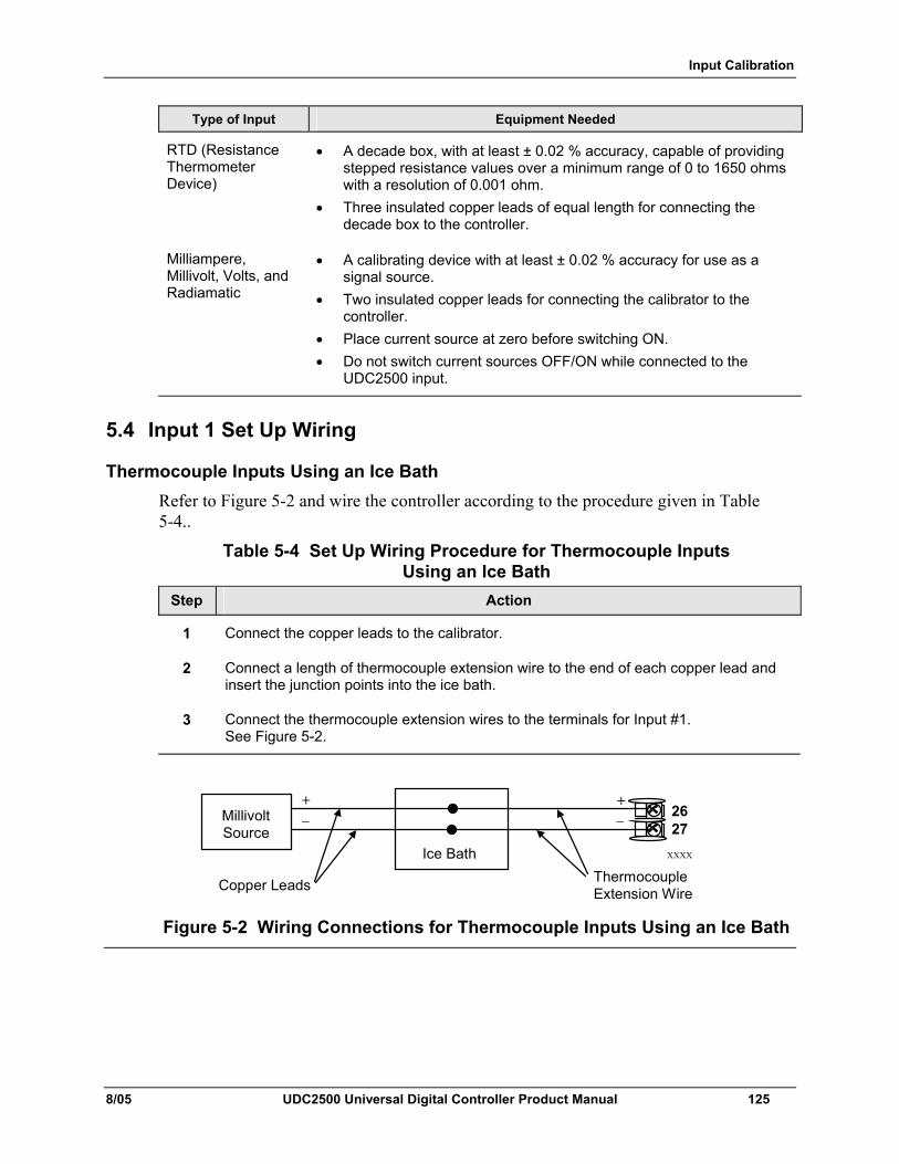
Input Calibration
8/05 UDC2500 Universal Digital Controller Product Manual 125
Type of Input Equipment Needed
RTD (Resistance Thermometer Device)
• A decade box, with at least ± 0.02 % accuracy, capable of providing stepped resistance values over a minimum range of 0 to 1650 ohms with a resolution of 0.001 ohm.
• Three insulated copper leads of equal length for connecting the decade box to the controller.
Milliampere, Millivolt, Volts, and Radiamatic
• A calibrating device with at least ± 0.02 % accuracy for use as a signal source.
• Two insulated copper leads for connecting the calibrator to the controller.
• Place current source at zero before switching ON. • Do not switch current sources OFF/ON while connected to the
UDC2500 input.
5.4 Input 1 Set Up Wiring
Thermocouple Inputs Using an Ice Bath Refer to Figure 5-2 and wire the controller according to the procedure given in Table 5-4..
Table 5-4 Set Up Wiring Procedure for Thermocouple Inputs Using an Ice Bath
Step Action
1 Connect the copper leads to the calibrator.
2 Connect a length of thermocouple extension wire to the end of each copper lead and insert the junction points into the ice bath.
3 Connect the thermocouple extension wires to the terminals for Input #1. See Figure 5-2.
XXXX
+ _ Millivolt
Source 26 27
+
Ice Bath
Copper Leads Thermocouple Extension Wire
_
Figure 5-2 Wiring Connections for Thermocouple Inputs Using an Ice Bath
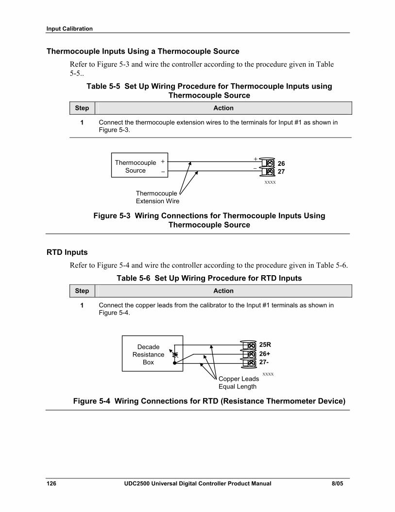
Input Calibration
126 UDC2500 Universal Digital Controller Product Manual 8/05
Thermocouple Inputs Using a Thermocouple Source Refer to Figure 5-3 and wire the controller according to the procedure given in Table 5-5..
Table 5-5 Set Up Wiring Procedure for Thermocouple Inputs using Thermocouple Source
Step Action
1 Connect the thermocouple extension wires to the terminals for Input #1 as shown in Figure 5-3.
XXXX
Thermocouple Source
Thermocouple Extension Wire
+ _
26 27
+ _
Figure 5-3 Wiring Connections for Thermocouple Inputs Using Thermocouple Source
RTD Inputs Refer to Figure 5-4 and wire the controller according to the procedure given in Table 5-6.
Table 5-6 Set Up Wiring Procedure for RTD Inputs Step Action
1 Connect the copper leads from the calibrator to the Input #1 terminals as shown in Figure 5-4.
XXXX
Decade Resistance
Box
25R 26+27-
Copper Leads Equal Length
Figure 5-4 Wiring Connections for RTD (Resistance Thermometer Device)
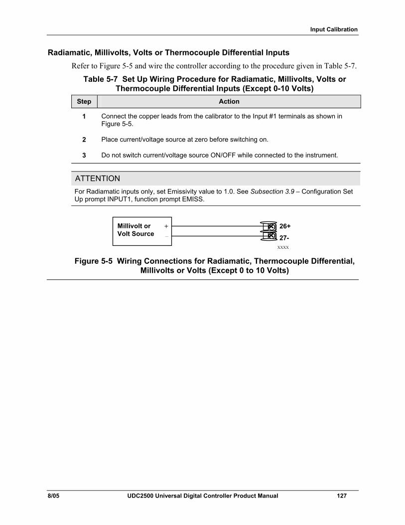
Input Calibration
8/05 UDC2500 Universal Digital Controller Product Manual 127
Radiamatic, Millivolts, Volts or Thermocouple Differential Inputs Refer to Figure 5-5 and wire the controller according to the procedure given in Table 5-7.
Table 5-7 Set Up Wiring Procedure for Radiamatic, Millivolts, Volts or Thermocouple Differential Inputs (Except 0-10 Volts)
Step Action
1 Connect the copper leads from the calibrator to the Input #1 terminals as shown in Figure 5-5.
2 Place current/voltage source at zero before switching on.
3 Do not switch current/voltage source ON/OFF while connected to the instrument.
ATTENTION For Radiamatic inputs only, set Emissivity value to 1.0. See Subsection 3.9 – Configuration Set Up prompt INPUT1, function prompt EMISS.
XXXX
Millivolt or Volt Source
26+
27-
+ _
Figure 5-5 Wiring Connections for Radiamatic, Thermocouple Differential, Millivolts or Volts (Except 0 to 10 Volts)
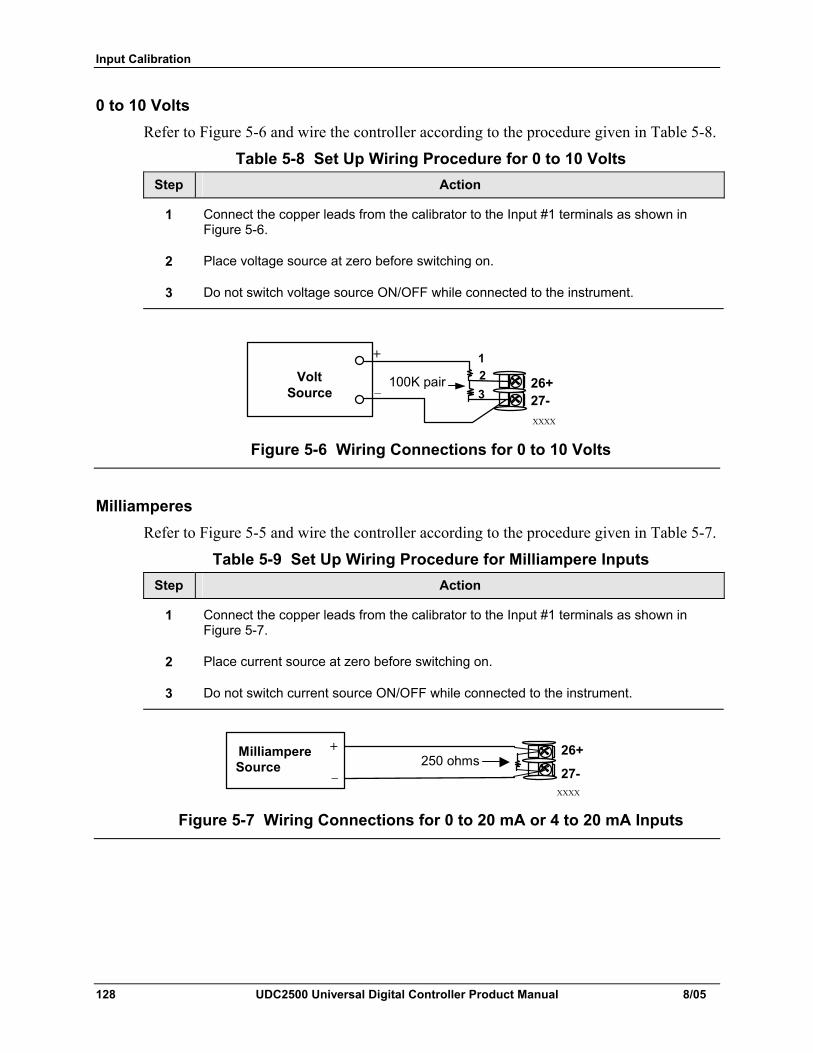
Input Calibration
128 UDC2500 Universal Digital Controller Product Manual 8/05
0 to 10 Volts Refer to Figure 5-6 and wire the controller according to the procedure given in Table 5-8.
Table 5-8 Set Up Wiring Procedure for 0 to 10 Volts Step Action
1 Connect the copper leads from the calibrator to the Input #1 terminals as shown in Figure 5-6.
2 Place voltage source at zero before switching on.
3 Do not switch voltage source ON/OFF while connected to the instrument.
XXXX
Volt Source _
+ 123
100K pair 26+ 27-
Figure 5-6 Wiring Connections for 0 to 10 Volts
Milliamperes Refer to Figure 5-5 and wire the controller according to the procedure given in Table 5-7.
Table 5-9 Set Up Wiring Procedure for Milliampere Inputs Step Action
1 Connect the copper leads from the calibrator to the Input #1 terminals as shown in Figure 5-7.
2 Place current source at zero before switching on.
3 Do not switch current source ON/OFF while connected to the instrument.
XXXX
Milliampere Source
26+
27-
+
_250 ohms
Figure 5-7 Wiring Connections for 0 to 20 mA or 4 to 20 mA Inputs
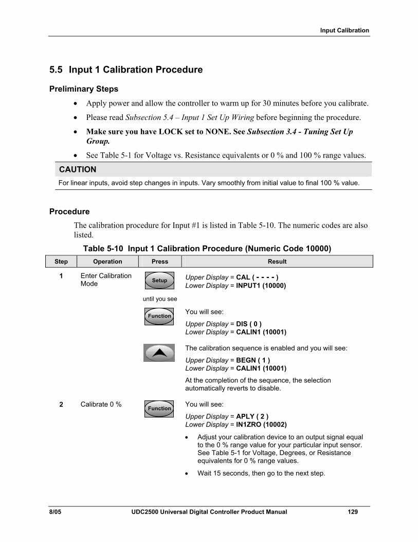
Input Calibration
8/05 UDC2500 Universal Digital Controller Product Manual 129
5.5 Input 1 Calibration Procedure
Preliminary Steps • Apply power and allow the controller to warm up for 30 minutes before you calibrate.
• Please read Subsection 5.4 – Input 1 Set Up Wiring before beginning the procedure.
• Make sure you have LOCK set to NONE. See Subsection 3.4 - Tuning Set Up Group.
• See Table 5-1 for Voltage vs. Resistance equivalents or 0 % and 100 % range values.
CAUTION For linear inputs, avoid step changes in inputs. Vary smoothly from initial value to final 100 % value.
Procedure The calibration procedure for Input #1 is listed in Table 5-10. The numeric codes are also listed.
Table 5-10 Input 1 Calibration Procedure (Numeric Code 10000) Step Operation Press Result
1 Enter Calibration Mode SetupSetup
until you see
Upper Display = CAL ( - - - - ) Lower Display = INPUT1 (10000)
FunctionFunctionFunction
You will see:
Upper Display = DIS ( 0 ) Lower Display = CALIN1 (10001)
The calibration sequence is enabled and you will see:
Upper Display = BEGN ( 1 ) Lower Display = CALIN1 (10001)
At the completion of the sequence, the selection automatically reverts to disable.
2 Calibrate 0 % FunctionFunctionFunction
You will see:
Upper Display = APLY ( 2 ) Lower Display = IN1ZRO (10002)
• Adjust your calibration device to an output signal equal to the 0 % range value for your particular input sensor. See Table 5-1 for Voltage, Degrees, or Resistance equivalents for 0 % range values.
• Wait 15 seconds, then go to the next step.
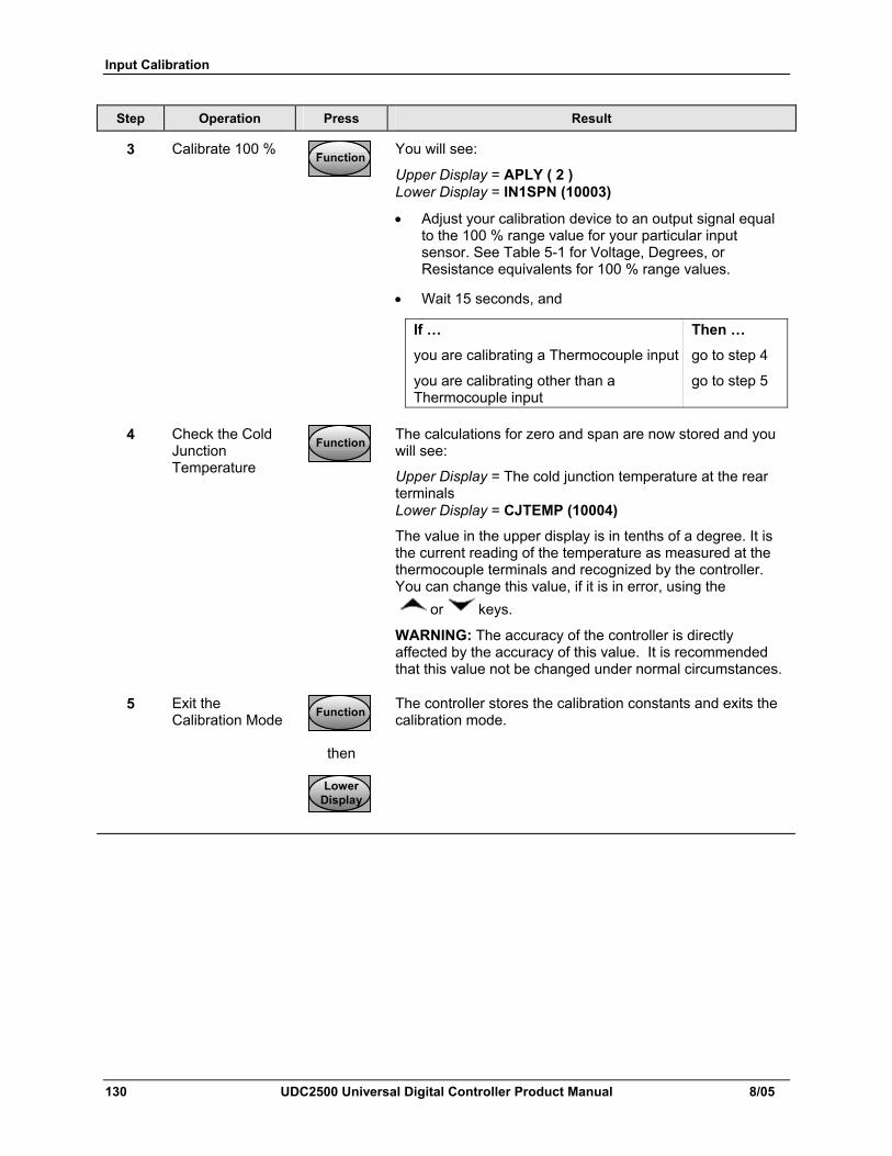
Input Calibration
130 UDC2500 Universal Digital Controller Product Manual 8/05
Step Operation Press Result
3 Calibrate 100 % FunctionFunctionFunction
You will see:
Upper Display = APLY ( 2 ) Lower Display = IN1SPN (10003)
• Adjust your calibration device to an output signal equal to the 100 % range value for your particular input sensor. See Table 5-1 for Voltage, Degrees, or Resistance equivalents for 100 % range values.
• Wait 15 seconds, and
If … Then …
you are calibrating a Thermocouple input go to step 4
you are calibrating other than a go to step 5 Thermocouple input
4 Check the Cold Junction Temperature
FunctionFunctionFunction
The calculations for zero and span are now stored and you will see:
Upper Display = The cold junction temperature at the rear terminals Lower Display = CJTEMP (10004)
The value in the upper display is in tenths of a degree. It is the current reading of the temperature as measured at the thermocouple terminals and recognized by the controller. You can change this value, if it is in error, using the
or keys.
WARNING: The accuracy of the controller is directly affected by the accuracy of this value. It is recommended that this value not be changed under normal circumstances.
5 Exit the Calibration Mode FunctionFunctionFunction
then
The controller stores the calibration constants and exits the calibration mode.
LowerDisplayLower
DisplayLower
Display
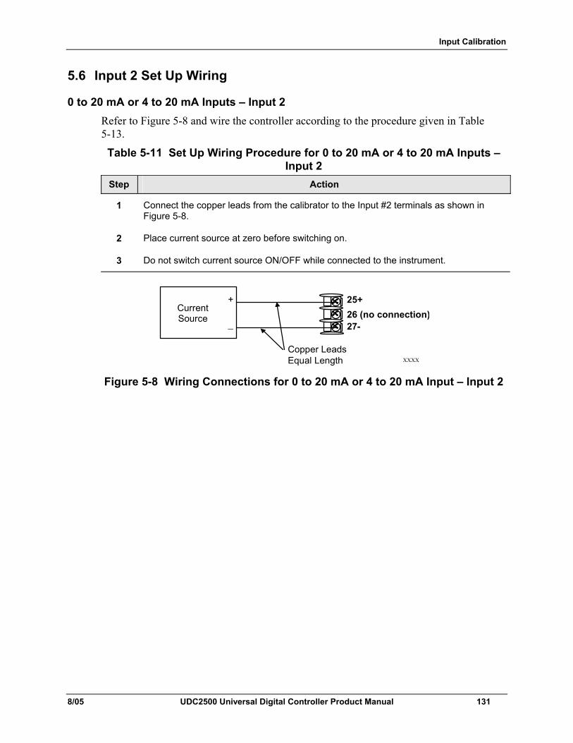
Input Calibration
8/05 UDC2500 Universal Digital Controller Product Manual 131
5.6 Input 2 Set Up Wiring
0 to 20 mA or 4 to 20 mA Inputs – Input 2 Refer to Figure 5-8 and wire the controller according to the procedure given in Table 5-13.
Table 5-11 Set Up Wiring Procedure for 0 to 20 mA or 4 to 20 mA Inputs – Input 2
Step Action
1 Connect the copper leads from the calibrator to the Input #2 terminals as shown in Figure 5-8.
2 Place current source at zero before switching on.
3 Do not switch current source ON/OFF while connected to the instrument.
XXXX
25+ 26 (no connection)27-
Copper Leads Equal Length
Current Source
+
_
Figure 5-8 Wiring Connections for 0 to 20 mA or 4 to 20 mA Input – Input 2
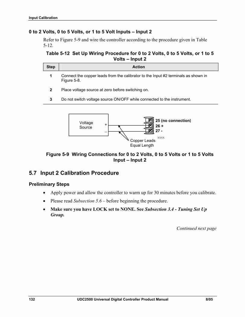
Input Calibration
132 UDC2500 Universal Digital Controller Product Manual 8/05
0 to 2 Volts, 0 to 5 Volts, or 1 to 5 Volt Inputs – Input 2 Refer to Figure 5-9 and wire the controller according to the procedure given in Table 5-12.
Table 5-12 Set Up Wiring Procedure for 0 to 2 Volts, 0 to 5 Volts, or 1 to 5 Volts – Input 2
Step Action
1 Connect the copper leads from the calibrator to the Input #2 terminals as shown in Figure 5-8.
2 Place voltage source at zero before switching on.
3 Do not switch voltage source ON/OFF while connected to the instrument.
XXXX
Voltage Source 26 +
27 -
Copper Leads Equal Length
+_
25 (no connection)
Figure 5-9 Wiring Connections for 0 to 2 Volts, 0 to 5 Volts or 1 to 5 Volts
Input – Input 2
5.7 Input 2 Calibration Procedure
Preliminary Steps • Apply power and allow the controller to warm up for 30 minutes before you calibrate.
• Please read Subsection 5.6 – before beginning the procedure.
• Make sure you have LOCK set to NONE. See Subsection 3.4 - Tuning Set Up Group.
Continued next page
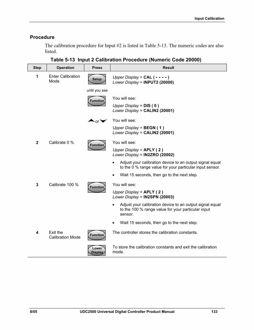
Input Calibration
8/05 UDC2500 Universal Digital Controller Product Manual 133
Procedure The calibration procedure for Input #2 is listed in Table 5-13. The numeric codes are also listed.
Table 5-13 Input 2 Calibration Procedure (Numeric Code 20000) Step Operation Press Result
1 Enter Calibration Mode SetupSetup
until you see
Upper Display = CAL ( - - - - ) Lower Display = INPUT2 (20000)
FunctionFunctionFunction
You will see:
Upper Display = DIS ( 0 ) Lower Display = CALIN2 (20001)
or You will see:
Upper Display = BEGN ( 1 ) Lower Display = CALIN2 (20001)
2 Calibrate 0 % FunctionFunctionFunction
You will see:
Upper Display = APLY ( 2 ) Lower Display = IN2ZRO (20002)
• Adjust your calibration device to an output signal equal to the 0 % range value for your particular input sensor.
• Wait 15 seconds, then go to the next step.
3 Calibrate 100 % FunctionFunctionFunction
You will see:
Upper Display = APLY ( 2 ) Lower Display = IN2SPN (20003)
• Adjust your calibration device to an output signal equal to the 100 % range value for your particular input sensor.
• Wait 15 seconds, then go to the next step.
4 FunctionFunctionFunction
The controller stores the calibration constants.
Exit the Calibration Mode
LowerDisplayLower
DisplayLower
Display
To store the calibration constants and exit the calibration mode.
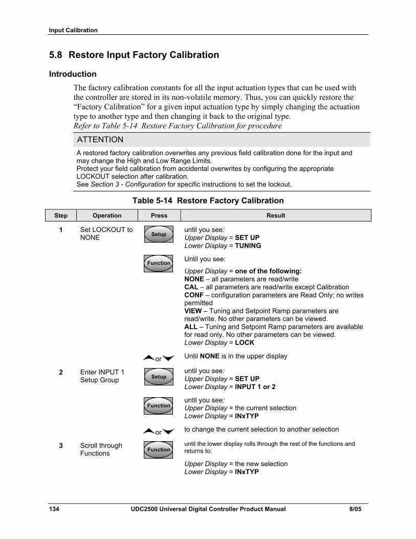
Input Calibration
134 UDC2500 Universal Digital Controller Product Manual 8/05
5.8 Restore Input Factory Calibration
Introduction The factory calibration constants for all the input actuation types that can be used with the controller are stored in its non-volatile memory. Thus, you can quickly restore the “Factory Calibration” for a given input actuation type by simply changing the actuation type to another type and then changing it back to the original type. Refer to Table 5-14 Restore Factory Calibration for procedure
ATTENTION A restored factory calibration overwrites any previous field calibration done for the input and may change the High and Low Range Limits. Protect your field calibration from accidental overwrites by configuring the appropriate LOCKOUT selection after calibration. See Section 3 - Configuration for specific instructions to set the lockout.
Table 5-14 Restore Factory Calibration
Step Operation Press Result
1 Set LOCKOUT to NONE SetupSetup
until you see: Upper Display = SET UP Lower Display = TUNING
FunctionFunctionFunction
Until you see:
Upper Display = one of the following: NONE – all parameters are read/write CAL – all parameters are read/write except Calibration CONF – configuration parameters are Read Only; no writes permitted VIEW – Tuning and Setpoint Ramp parameters are read/write. No other parameters can be viewed. ALL – Tuning and Setpoint Ramp parameters are available for read only. No other parameters can be viewed. Lower Display = LOCK
or Until NONE is in the upper display
2 Enter INPUT 1 Setup Group SetupSetup
until you see: Upper Display = SET UP Lower Display = INPUT 1 or 2
FunctionFunctionFunction
until you see: Upper Display = the current selection Lower Display = INxTYP
or to change the current selection to another selection
3 Scroll through Functions FunctionFunctionFunction
until the lower display rolls through the rest of the functions and returns to:
Upper Display = the new selection Lower Display = INxTYP
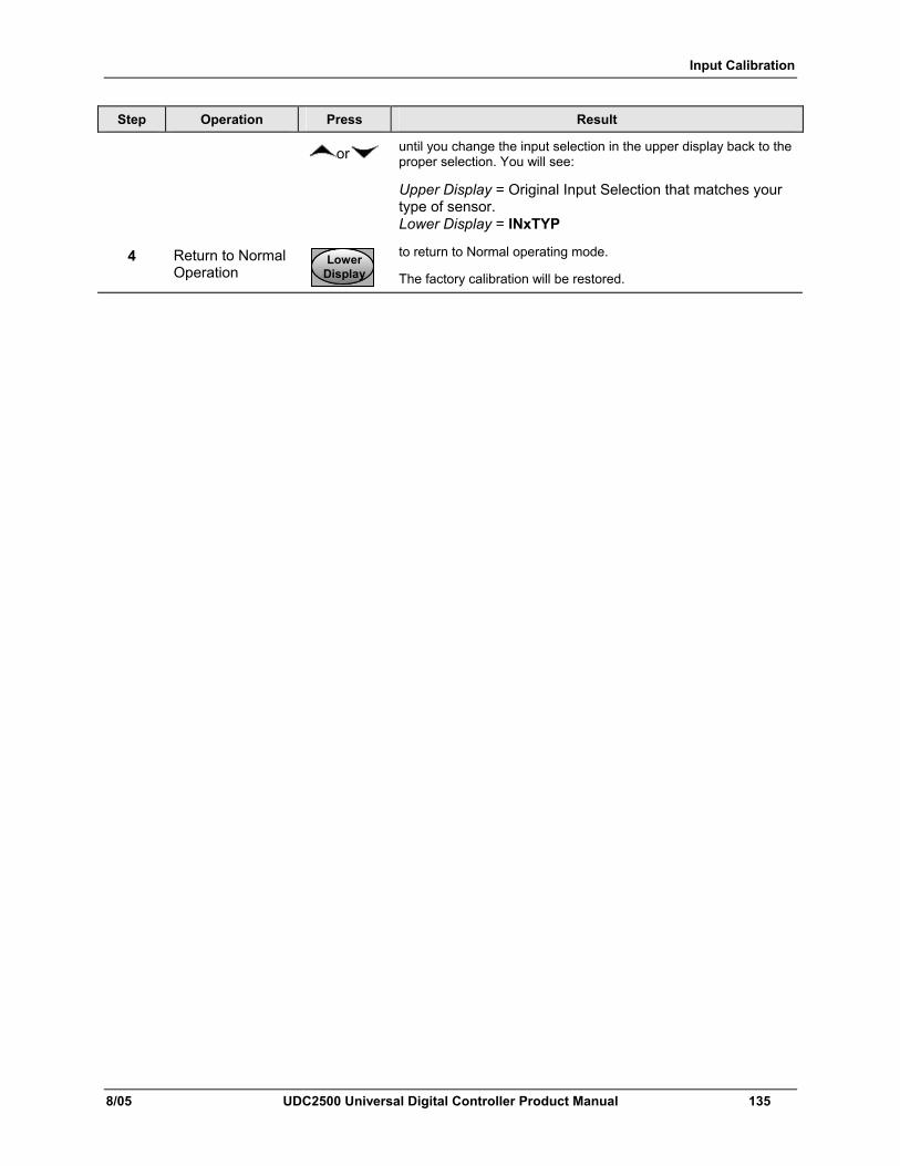
Input Calibration
8/05 UDC2500 Universal Digital Controller Product Manual 135
Step Operation Press Result
or until you change the input selection in the upper display back to the proper selection. You will see:
Upper Display = Original Input Selection that matches your type of sensor. Lower Display = INxTYP
4 Return to Normal Operation
LowerDisplayLower
DisplayLower
Display
to return to Normal operating mode.
The factory calibration will be restored.

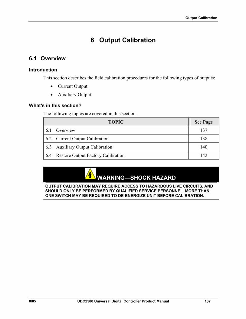
Output Calibration
8/05 UDC2500 Universal Digital Controller Product Manual 137
6 Output Calibration
6.1 Overview
Introduction This section describes the field calibration procedures for the following types of outputs:
• Current Output
• Auxiliary Output
What's in this section? The following topics are covered in this section.
TOPIC See Page
6.1 Overview 137
6.2 Current Output Calibration 138
6.3 Auxiliary Output Calibration 140
6.4 Restore Output Factory Calibration 142
WARNING—SHOCK HAZARD
OUTPUT CALIBRATION MAY REQUIRE ACCESS TO HAZARDOUS LIVE CIRCUITS, AND SHOULD ONLY BE PERFORMED BY QUALIFIED SERVICE PERSONNEL. MORE THAN ONE SWITCH MAY BE REQUIRED TO DE-ENERGIZE UNIT BEFORE CALIBRATION.
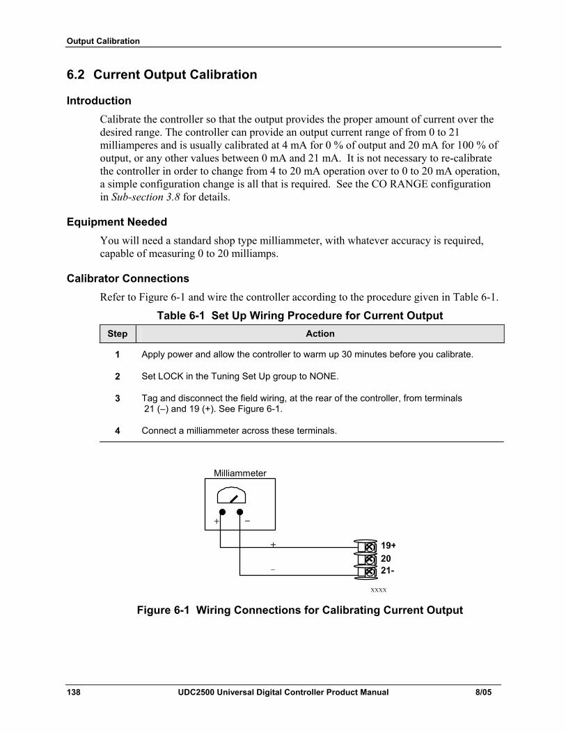
Output Calibration
138 UDC2500 Universal Digital Controller Product Manual 8/05
6.2 Current Output Calibration
Introduction Calibrate the controller so that the output provides the proper amount of current over the desired range. The controller can provide an output current range of from 0 to 21 milliamperes and is usually calibrated at 4 mA for 0 % of output and 20 mA for 100 % of output, or any other values between 0 mA and 21 mA. It is not necessary to re-calibrate the controller in order to change from 4 to 20 mA operation over to 0 to 20 mA operation, a simple configuration change is all that is required. See the CO RANGE configuration in Sub-section 3.8 for details.
Equipment Needed You will need a standard shop type milliammeter, with whatever accuracy is required, capable of measuring 0 to 20 milliamps.
Calibrator Connections Refer to Figure 6-1 and wire the controller according to the procedure given in Table 6-1.
Table 6-1 Set Up Wiring Procedure for Current Output Step Action
1 Apply power and allow the controller to warm up 30 minutes before you calibrate.
2 Set LOCK in the Tuning Set Up group to NONE.
3 Tag and disconnect the field wiring, at the rear of the controller, from terminals 21 (–) and 19 (+). See Figure 6-1.
4 Connect a milliammeter across these terminals.
XXXX
Milliammeter
+ _
+
_
19+20 21-
Figure 6-1 Wiring Connections for Calibrating Current Output
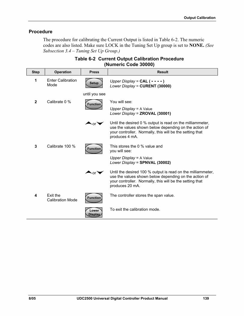
Output Calibration
8/05 UDC2500 Universal Digital Controller Product Manual 139
Procedure The procedure for calibrating the Current Output is listed in Table 6-2. The numeric codes are also listed. Make sure LOCK in the Tuning Set Up group is set to NONE. (See Subsection 3.4 – Tuning Set Up Group.)
Table 6-2 Current Output Calibration Procedure (Numeric Code 30000)
Step Operation Press Result
1 Enter Calibration Mode SetupSetup
until you see
Upper Display = CAL ( - - - - ) Lower Display = CURENT (30000)
2 Calibrate 0 % FunctionFunctionFunction
You will see:
Upper Display = A Value Lower Display = ZROVAL (30001)
or
Until the desired 0 % output is read on the milliammeter, use the values shown below depending on the action of your controller. Normally, this will be the setting that produces 4 mA.
3 Calibrate 100 % FunctionFunctionFunction
This stores the 0 % value and you will see:
Upper Display = A Value Lower Display = SPNVAL (30002)
or
Until the desired 100 % output is read on the milliammeter, use the values shown below depending on the action of your controller. Normally, this will be the setting that produces 20 mA.
4 FunctionFunctionFunction
The controller stores the span value.
Exit the Calibration Mode
LowerDisplayLower
DisplayLower
Display
To exit the calibration mode.
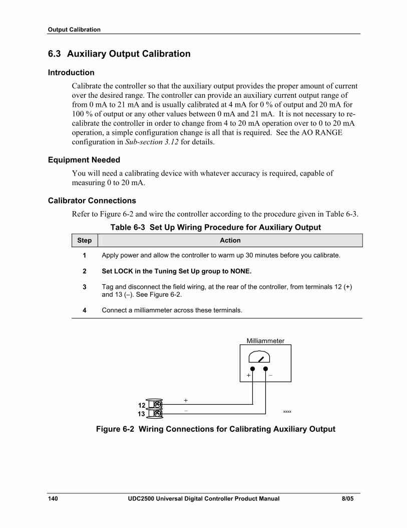
Output Calibration
140 UDC2500 Universal Digital Controller Product Manual 8/05
6.3 Auxiliary Output Calibration
Introduction Calibrate the controller so that the auxiliary output provides the proper amount of current over the desired range. The controller can provide an auxiliary current output range of from 0 mA to 21 mA and is usually calibrated at 4 mA for 0 % of output and 20 mA for 100 % of output or any other values between 0 mA and 21 mA. It is not necessary to re-calibrate the controller in order to change from 4 to 20 mA operation over to 0 to 20 mA operation, a simple configuration change is all that is required. See the AO RANGE configuration in Sub-section 3.12 for details.
Equipment Needed You will need a calibrating device with whatever accuracy is required, capable of measuring 0 to 20 mA.
Calibrator Connections Refer to Figure 6-2 and wire the controller according to the procedure given in Table 6-3.
Table 6-3 Set Up Wiring Procedure for Auxiliary Output Step Action
1 Apply power and allow the controller to warm up 30 minutes before you calibrate.
2 Set LOCK in the Tuning Set Up group to NONE.
3 Tag and disconnect the field wiring, at the rear of the controller, from terminals 12 (+) and 13 (–). See Figure 6-2.
4 Connect a milliammeter across these terminals.
xxxx 12 13
Milliammeter
+ _
+_
Figure 6-2 Wiring Connections for Calibrating Auxiliary Output
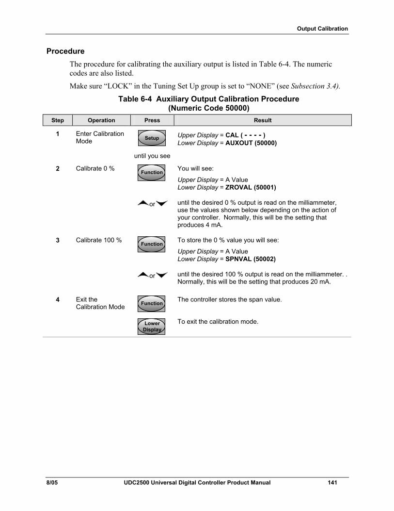
Output Calibration
8/05 UDC2500 Universal Digital Controller Product Manual 141
Procedure The procedure for calibrating the auxiliary output is listed in Table 6-4. The numeric codes are also listed.
Make sure “LOCK” in the Tuning Set Up group is set to “NONE” (see Subsection 3.4).
Table 6-4 Auxiliary Output Calibration Procedure (Numeric Code 50000)
Step Operation Press Result
1 Enter Calibration Mode SetupSetup
until you see
Upper Display = CAL ( - - - - ) Lower Display = AUXOUT (50000)
2 Calibrate 0 % FunctionFunctionFunction
You will see:
Upper Display = A Value Lower Display = ZROVAL (50001)
or until the desired 0 % output is read on the milliammeter, use the values shown below depending on the action of your controller. Normally, this will be the setting that produces 4 mA.
3 Calibrate 100 % FunctionFunctionFunction
To store the 0 % value you will see:
Upper Display = A Value Lower Display = SPNVAL (50002)
or until the desired 100 % output is read on the milliammeter. . Normally, this will be the setting that produces 20 mA.
4 FunctionFunctionFunction
The controller stores the span value.
Exit the Calibration Mode
LowerDisplayLower
DisplayLower
Display
To exit the calibration mode.
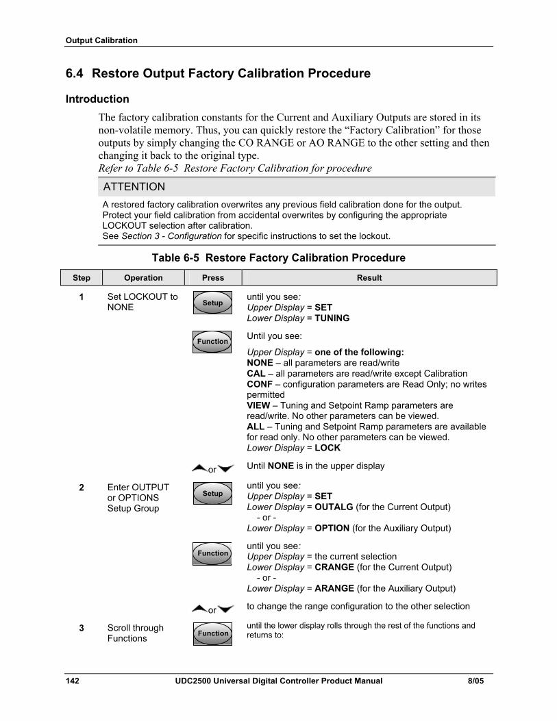
Output Calibration
142 UDC2500 Universal Digital Controller Product Manual 8/05
6.4 Restore Output Factory Calibration Procedure
Introduction The factory calibration constants for the Current and Auxiliary Outputs are stored in its non-volatile memory. Thus, you can quickly restore the “Factory Calibration” for those outputs by simply changing the CO RANGE or AO RANGE to the other setting and then changing it back to the original type. Refer to Table 6-5 Restore Factory Calibration for procedure
ATTENTION A restored factory calibration overwrites any previous field calibration done for the output. Protect your field calibration from accidental overwrites by configuring the appropriate LOCKOUT selection after calibration. See Section 3 - Configuration for specific instructions to set the lockout.
Table 6-5 Restore Factory Calibration Procedure
Step Operation Press Result
1 Set LOCKOUT to NONE SetupSetup
until you see: Upper Display = SET Lower Display = TUNING
FunctionFunctionFunction
Until you see:
Upper Display = one of the following: NONE – all parameters are read/write CAL – all parameters are read/write except Calibration CONF – configuration parameters are Read Only; no writes permitted VIEW – Tuning and Setpoint Ramp parameters are read/write. No other parameters can be viewed. ALL – Tuning and Setpoint Ramp parameters are available for read only. No other parameters can be viewed. Lower Display = LOCK
or Until NONE is in the upper display
2 Enter OUTPUT or OPTIONS Setup Group
SetupSetup
until you see: Upper Display = SET Lower Display = OUTALG (for the Current Output) - or - Lower Display = OPTION (for the Auxiliary Output)
FunctionFunctionFunction
until you see: Upper Display = the current selection Lower Display = CRANGE (for the Current Output) - or - Lower Display = ARANGE (for the Auxiliary Output)
or to change the range configuration to the other selection
3 Scroll through Functions FunctionFunctionFunction
until the lower display rolls through the rest of the functions and returns to:
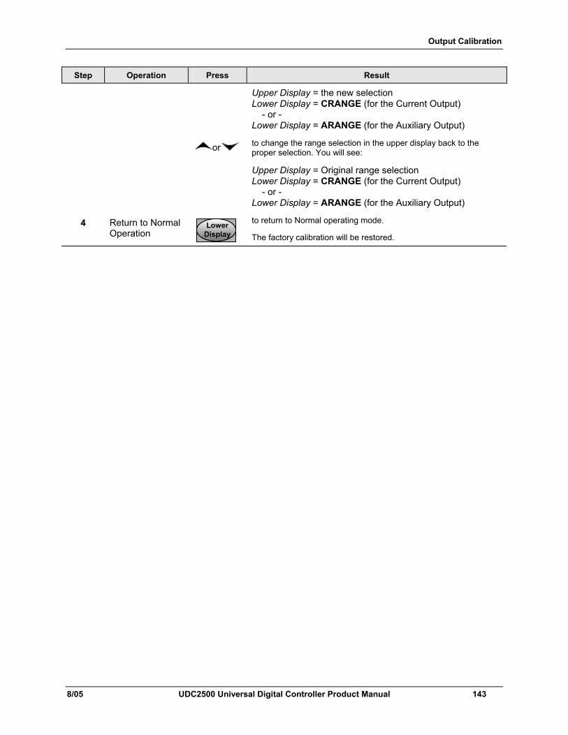
Output Calibration
8/05 UDC2500 Universal Digital Controller Product Manual 143
Step Operation Press Result
Upper Display = the new selection Lower Display = CRANGE (for the Current Output) - or - Lower Display = ARANGE (for the Auxiliary Output)
or to change the range selection in the upper display back to the proper selection. You will see:
Upper Display = Original range selection Lower Display = CRANGE (for the Current Output) - or - Lower Display = ARANGE (for the Auxiliary Output)
4 Return to Normal Operation
LowerDisplayLower
DisplayLower
Display
to return to Normal operating mode.
The factory calibration will be restored.
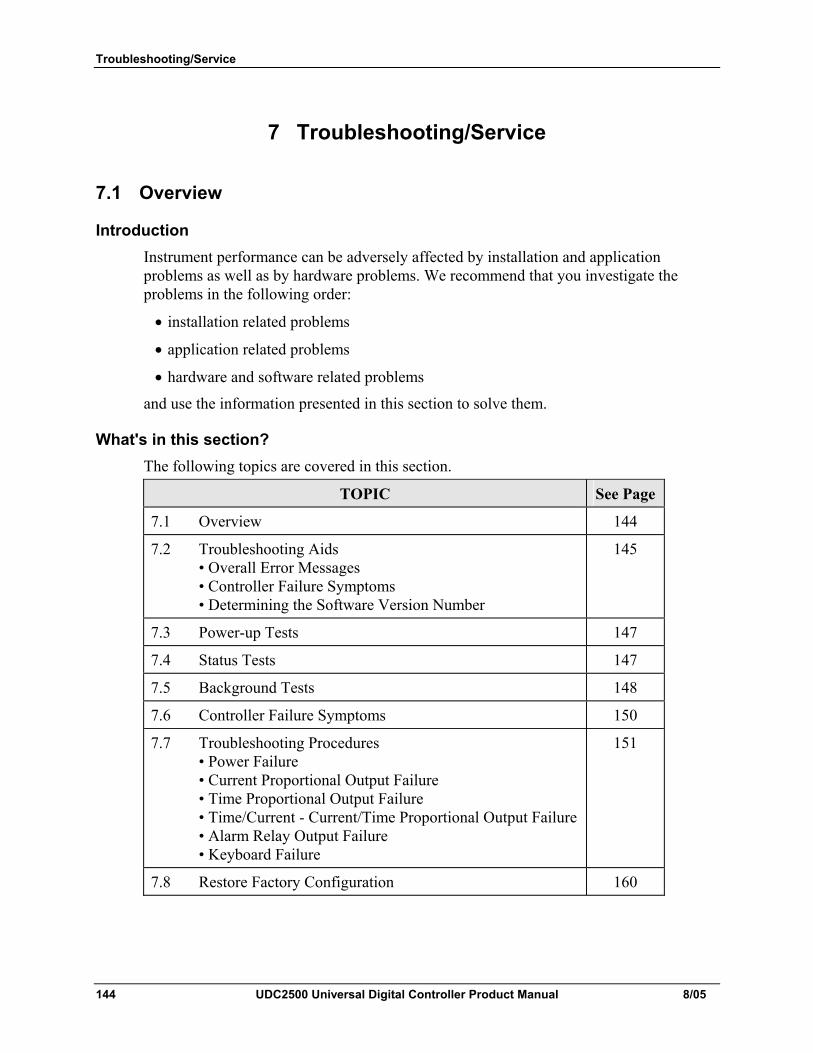
Troubleshooting/Service
144 UDC2500 Universal Digital Controller Product Manual 8/05
7 Troubleshooting/Service
7.1 Overview
Introduction Instrument performance can be adversely affected by installation and application problems as well as by hardware problems. We recommend that you investigate the problems in the following order:
• installation related problems
• application related problems
• hardware and software related problems
and use the information presented in this section to solve them.
What's in this section? The following topics are covered in this section.
TOPIC See Page
7.1 Overview 144
7.2 Troubleshooting Aids • Overall Error Messages • Controller Failure Symptoms • Determining the Software Version Number
145
7.3 Power-up Tests 147
7.4 Status Tests 147
7.5 Background Tests 148
7.6 Controller Failure Symptoms 150
7.7 Troubleshooting Procedures • Power Failure • Current Proportional Output Failure • Time Proportional Output Failure • Time/Current - Current/Time Proportional Output Failure • Alarm Relay Output Failure • Keyboard Failure
151
7.8 Restore Factory Configuration 160
Troubleshooting/Service
8/05 UDC2500 Universal Digital Controller Product Manual 145
Installation related problems Read the Installation section in this manual to make sure the UDC2500 has been properly installed. The installation section provides information on protection against electrical noise, connecting external equipment to the controller, and shielding and routing external wiring.
ATTENTION System noise induced into the controller will result in diagnostic error messages recurring. If the diagnostic error messages can be cleared, it indicates a “soft” failure and is probably noise related.
If system noise is suspected, completely isolate the controller from all field wiring. Use calibration sources to simulate PV and check all controller functions; i.e. Gain, Rate, Reset, Output, Alarms, etc.
Application related problems Review the application of the controller; then, if necessary, direct your questions to the local sales office.
Hardware and software related problems Use the troubleshooting error message prompts and controller failure symptoms to identify typical failures, which may occur in the controller. Follow the troubleshooting procedures to correct them.
7.2 Troubleshooting Aids
Overall error messages An error message can occur:
• At power-up. See Subsection 7.3.
• When the Status Tests are requested. See Subsection 7.4.
• During continuous background tests while in normal operation. See Subsection 7.5.
Controller failure symptoms Other failures may occur that deal with the Power, Output, or Alarms. Refer to the controller failure symptom in Table 7-4 to determine what is wrong and the troubleshooting procedures to use to correct the problem.
Check installation If a set of symptoms still persists, refer to Section 2 - Installation and ensure proper installation and proper use of the controller in the system.
Determining the software version Table 7-1 lists the procedure for identifying the software version number.
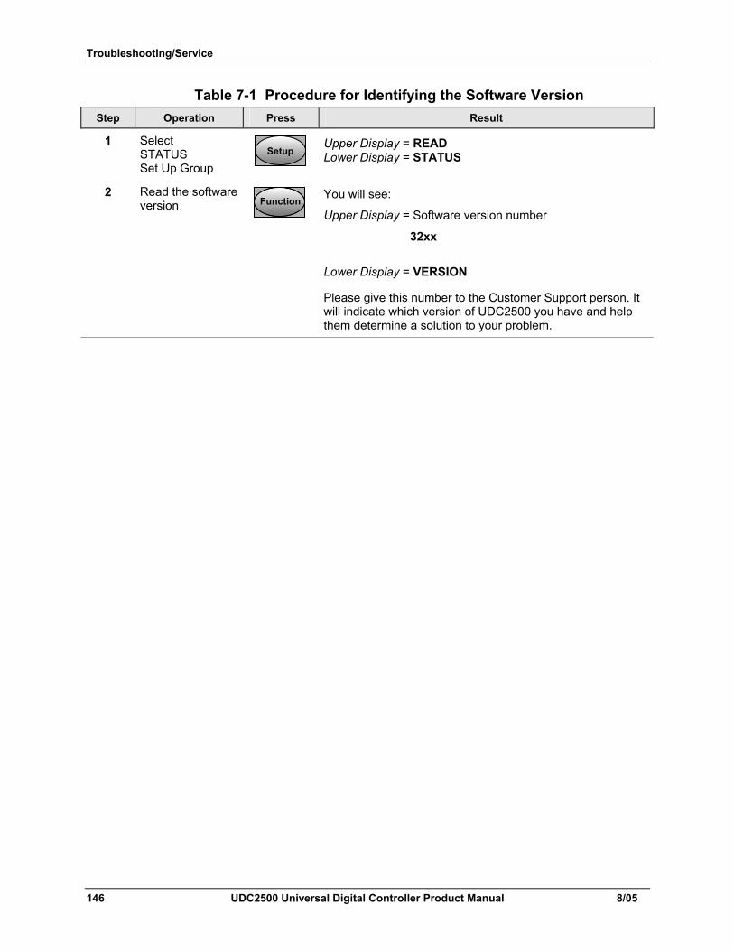
Troubleshooting/Service
146 UDC2500 Universal Digital Controller Product Manual 8/05
Table 7-1 Procedure for Identifying the Software Version Step Operation Press Result
1 Select STATUS Set Up Group
SetupSetup
Upper Display = READ Lower Display = STATUS
2 Read the software version FunctionFunctionFunction
You will see:
Upper Display = Software version number
32xx
Lower Display = VERSION
Please give this number to the Customer Support person. It will indicate which version of UDC2500 you have and help them determine a solution to your problem.
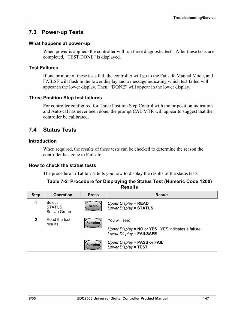
Troubleshooting/Service
8/05 UDC2500 Universal Digital Controller Product Manual 147
7.3 Power-up Tests
What happens at power-up When power is applied, the controller will run three diagnostic tests. After these tests are completed, “TEST DONE” is displayed.
Test Failures If one or more of these tests fail, the controller will go to the Failsafe Manual Mode, and FAILSF will flash in the lower display and a message indicating which test failed will appear in the lower display. Then, “DONE” will appear in the lower display.
Three Position Step test failures For controller configured for Three Position Step Control with motor position indication and Auto-cal has never been done, the prompt CAL MTR will appear to suggest that the controller be calibrated.
7.4 Status Tests
Introduction When required, the results of these tests can be checked to determine the reason the controller has gone to Failsafe.
How to check the status tests The procedure in Table 7-2 tells you how to display the results of the status tests.
Table 7-2 Procedure for Displaying the Status Test (Numeric Code 1200) Results
Step Operation Press Result
1 Select STATUS Set Up Group
SetupSetup
Upper Display = READ Lower Display = STATUS
2 Read the test results FunctionFunctionFunction
You will see:
Upper Display = NO or YES YES indicates a failure Lower Display = FAILSAFE
FunctionFunctionFunction
Upper Display = PASS or FAIL Lower Display = TEST
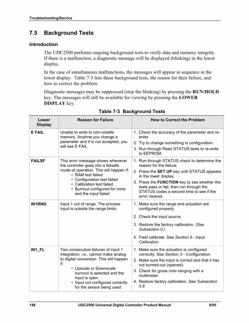
Troubleshooting/Service
148 UDC2500 Universal Digital Controller Product Manual 8/05
7.5 Background Tests
Introduction The UDC2500 performs ongoing background tests to verify data and memory integrity. If there is a malfunction, a diagnostic message will be displayed (blinking) in the lower display.
In the case of simultaneous malfunctions, the messages will appear in sequence in the lower display. Table 7-3 lists these background tests, the reason for their failure, and how to correct the problem.
Diagnostic messages may be suppressed (stop the blinking) by pressing the RUN/HOLD key. The messages will still be available for viewing by pressing the LOWER DISPLAY key.
Table 7-3 Background Tests Lower
Display Reason for Failure How to Correct the Problem
E FAIL Unable to write to non-volatile memory. Anytime you change a parameter and it is not accepted, you will see E FAIL.
1. Check the accuracy of the parameter and re-enter.
2. Try to change something in configuration. 3. Run through Read STATUS tests to re-write
to EEPROM.
FAILSF This error message shows whenever the controller goes into a failsafe mode of operation. This will happen if: • RAM test failed • Configuration test failed • Calibration test failed • Burnout configured for none
and the input failed.
1. Run through STATUS check to determine the reason for the failure.
2. Press the SET UP key until STATUS appears in the lower display.
3. Press the FUNCTION key to see whether the tests pass or fail, then run through the STATUS codes a second time to see if the error cleared.
IN1RNG Input 1 out of range. The process input is outside the range limits.
1. Make sure the range and actuation are configured properly.
2. Check the input source.
3. Restore the factory calibration. (See Subsection 0.)
4. Field calibrate. See Section 5 - Input Calibration.
IN1_FL Two consecutive failures of input 1 integration; i.e., cannot make analog to digital conversion. This will happen if: • Upscale or Downscale
burnout is selected and the input is open
• Input not configured correctly for the sensor being used
1. Make sure the actuation is configured correctly. See Section 3 - Configuration.
2. Make sure the input is correct and that it has not burned-out (opened).
3. Check for gross over-ranging with a multimeter.
4. Restore factory calibration. See Subsection 5.8
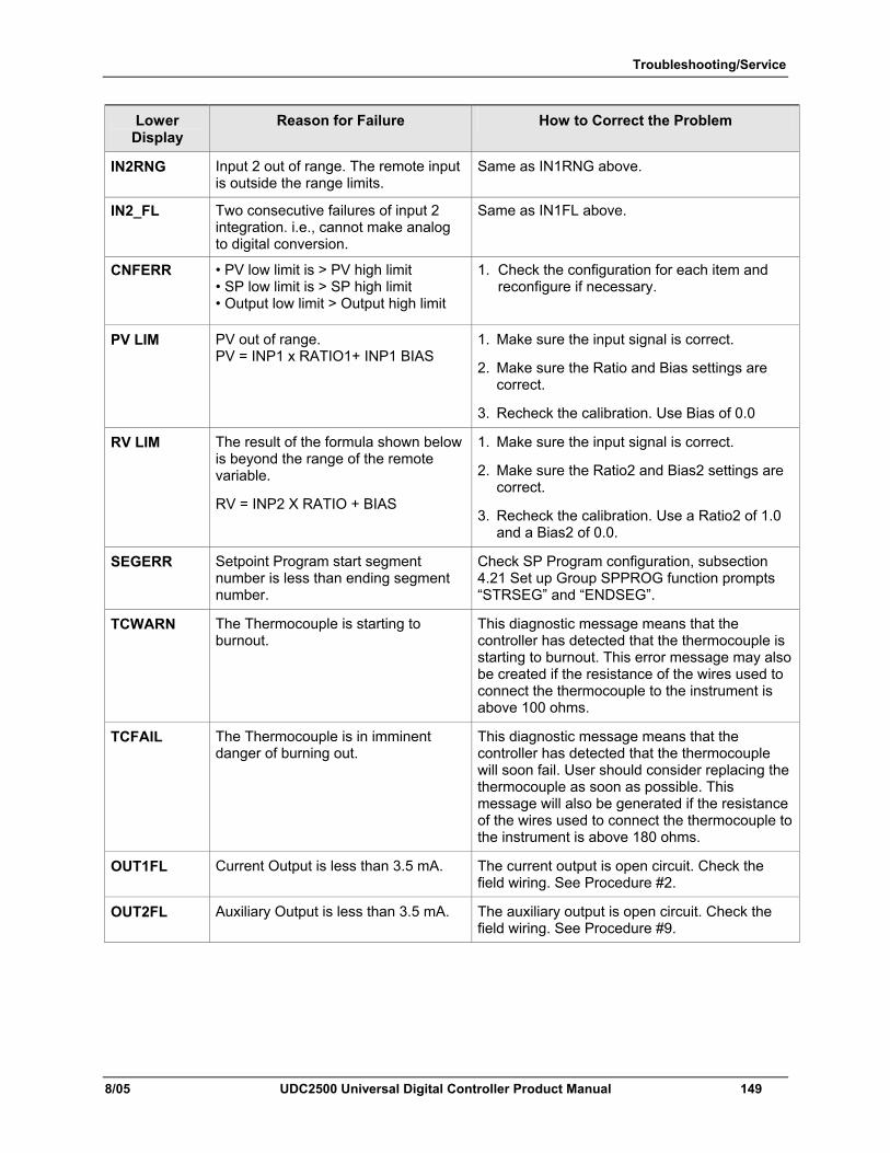
Troubleshooting/Service
8/05 UDC2500 Universal Digital Controller Product Manual 149
Lower Display
Reason for Failure How to Correct the Problem
IN2RNG Input 2 out of range. The remote input is outside the range limits.
Same as IN1RNG above.
IN2_FL Two consecutive failures of input 2 integration. i.e., cannot make analog to digital conversion.
Same as IN1FL above.
CNFERR • PV low limit is > PV high limit • SP low limit is > SP high limit • Output low limit > Output high limit
1. Check the configuration for each item and reconfigure if necessary.
PV LIM PV out of range. PV = INP1 x RATIO1+ INP1 BIAS
1. Make sure the input signal is correct.
2. Make sure the Ratio and Bias settings are correct.
3. Recheck the calibration. Use Bias of 0.0
RV LIM The result of the formula shown below is beyond the range of the remote variable.
RV = INP2 X RATIO + BIAS
1. Make sure the input signal is correct.
2. Make sure the Ratio2 and Bias2 settings are correct.
3. Recheck the calibration. Use a Ratio2 of 1.0 and a Bias2 of 0.0.
SEGERR Setpoint Program start segment number is less than ending segment number.
Check SP Program configuration, subsection 4.21 Set up Group SPPROG function prompts “STRSEG” and “ENDSEG”.
TCWARN The Thermocouple is starting to burnout.
This diagnostic message means that the controller has detected that the thermocouple is starting to burnout. This error message may also be created if the resistance of the wires used to connect the thermocouple to the instrument is above 100 ohms.
TCFAIL The Thermocouple is in imminent danger of burning out.
This diagnostic message means that the controller has detected that the thermocouple will soon fail. User should consider replacing the thermocouple as soon as possible. This message will also be generated if the resistance of the wires used to connect the thermocouple to the instrument is above 180 ohms.
OUT1FL Current Output is less than 3.5 mA. The current output is open circuit. Check the field wiring. See Procedure #2.
OUT2FL Auxiliary Output is less than 3.5 mA. The auxiliary output is open circuit. Check the field wiring. See Procedure #9.
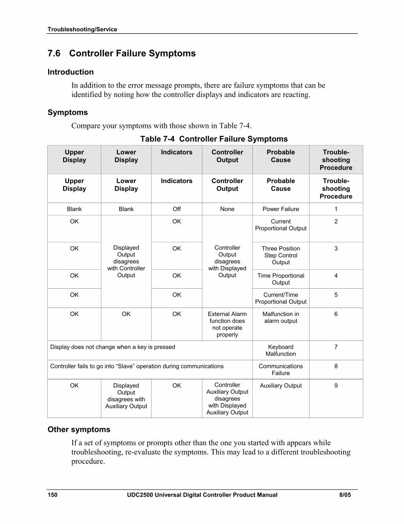
Troubleshooting/Service
150 UDC2500 Universal Digital Controller Product Manual 8/05
7.6 Controller Failure Symptoms
Introduction In addition to the error message prompts, there are failure symptoms that can be identified by noting how the controller displays and indicators are reacting.
Symptoms Compare your symptoms with those shown in Table 7-4.
Table 7-4 Controller Failure Symptoms Upper
Display Lower
Display Indicators Controller
Output Probable
Cause Trouble- shooting
Procedure
Upper Display
Lower Display
Indicators Controller Output
Probable Cause
Trouble- shooting
Procedure
Blank Blank Off None Power Failure 1
OK OK Current Proportional Output
2
OK OK Three Position Step Control
Output
3
OK OK Time Proportional Output
4
OK
Displayed Output
disagrees with Controller
Output
OK
Controller Output
disagrees with Displayed
Output
Current/Time Proportional Output
5
OK OK OK External Alarm function does not operate
properly
Malfunction in alarm output
6
Display does not change when a key is pressed Keyboard Malfunction
7
Controller fails to go into “Slave” operation during communications Communications Failure
8
OK Displayed Output
disagrees with Auxiliary Output
OK Controller Auxiliary Output
disagrees with Displayed
Auxiliary Output
Auxiliary Output 9
Other symptoms If a set of symptoms or prompts other than the one you started with appears while troubleshooting, re-evaluate the symptoms. This may lead to a different troubleshooting procedure.
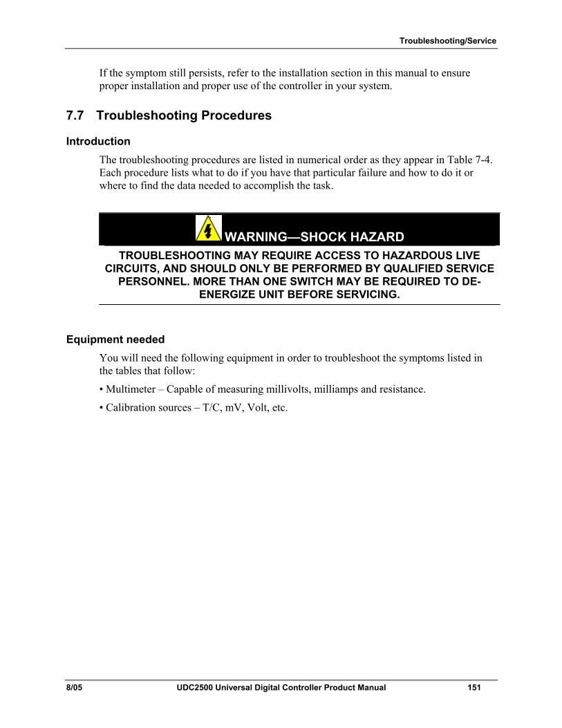
Troubleshooting/Service
8/05 UDC2500 Universal Digital Controller Product Manual 151
If the symptom still persists, refer to the installation section in this manual to ensure proper installation and proper use of the controller in your system.
7.7 Troubleshooting Procedures
Introduction The troubleshooting procedures are listed in numerical order as they appear in Table 7-4. Each procedure lists what to do if you have that particular failure and how to do it or where to find the data needed to accomplish the task.
WARNING—SHOCK HAZARD TROUBLESHOOTING MAY REQUIRE ACCESS TO HAZARDOUS LIVE
CIRCUITS, AND SHOULD ONLY BE PERFORMED BY QUALIFIED SERVICE PERSONNEL. MORE THAN ONE SWITCH MAY BE REQUIRED TO DE-
ENERGIZE UNIT BEFORE SERVICING.
Equipment needed You will need the following equipment in order to troubleshoot the symptoms listed in the tables that follow:
• Multimeter – Capable of measuring millivolts, milliamps and resistance.
• Calibration sources – T/C, mV, Volt, etc.
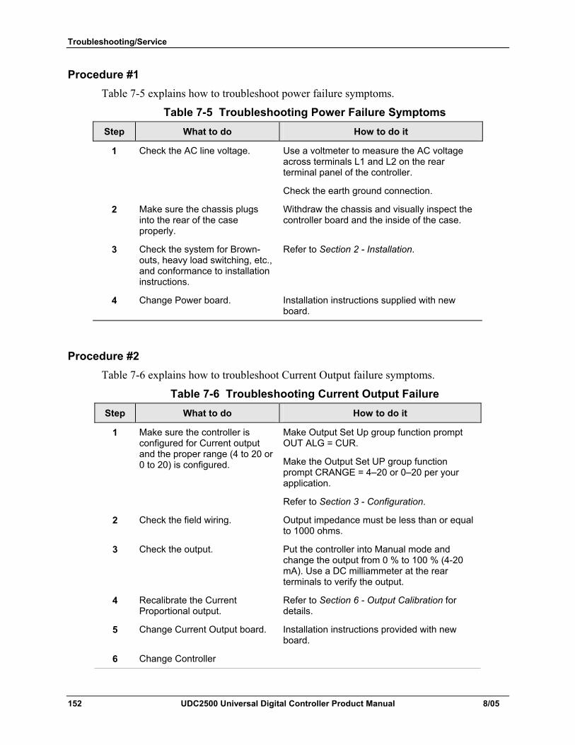
Troubleshooting/Service
152 UDC2500 Universal Digital Controller Product Manual 8/05
Procedure #1 Table 7-5 explains how to troubleshoot power failure symptoms.
Table 7-5 Troubleshooting Power Failure Symptoms Step What to do How to do it
1 Check the AC line voltage. Use a voltmeter to measure the AC voltage across terminals L1 and L2 on the rear terminal panel of the controller.
Check the earth ground connection.
2 Make sure the chassis plugs into the rear of the case properly.
Withdraw the chassis and visually inspect the controller board and the inside of the case.
3 Check the system for Brown-outs, heavy load switching, etc., and conformance to installation instructions.
Refer to Section 2 - Installation.
4 Change Power board. Installation instructions supplied with new board.
Procedure #2 Table 7-6 explains how to troubleshoot Current Output failure symptoms.
Table 7-6 Troubleshooting Current Output Failure Step What to do How to do it
1 Make sure the controller is configured for Current output and the proper range (4 to 20 or 0 to 20) is configured.
Make Output Set Up group function prompt OUT ALG = CUR.
Make the Output Set UP group function prompt CRANGE = 4–20 or 0–20 per your application.
Refer to Section 3 - Configuration.
2 Check the field wiring. Output impedance must be less than or equal to 1000 ohms.
3 Check the output. Put the controller into Manual mode and change the output from 0 % to 100 % (4-20 mA). Use a DC milliammeter at the rear terminals to verify the output.
4 Recalibrate the Current Proportional output.
Refer to Section 6 - Output Calibration for details.
5 Change Current Output board. Installation instructions provided with new board.
6 Change Controller
Troubleshooting/Service
8/05 UDC2500 Universal Digital Controller Product Manual 153
Procedure #3 Table 7-7 explains how to troubleshoot Position Proportional Output failure symptoms.
Table 7-7 Troubleshooting Three Position Step Control Output Failure Step What to do How to do it
1 Make certain that the controller is configured for Three Position Step control.
Make Output Algorithm Set Up group function prompt OUT ALG = TPSC.
Refer to Section 3.8.
2 Check the field wiring. Refer to Section 2 - Installation for details.
3 Check the output. Put the controller into Manual mode and change the output from 0 % to 100 %.
4 Check whether the motor drives in both directions.
Remove controller and short out Output 1 or Output 2. The motor should go to either open or closed. If it does controller is ok. If not, repeat Step 1.
5 Check whether the motor drives in either direction. If the motor does not drive in either direction, check the motor. If the motor drives in one direction but not the other, go to Step 6
Refer to the motor instructions.
6 Make sure the output relays are actuating properly.
Put the controller into Manual mode. Vary the output above and below the present value. Observe “OT” in the Lower Display and the Relay Annunciators on the operator interface.
If they are not working properly, check the field wiring, then go to Step 5.
If they are, go to Step 7.
7 Change the two Output Relays or the Dual Relay Board (depending upon unit)
Installation instructions supplied with the new relays or board.
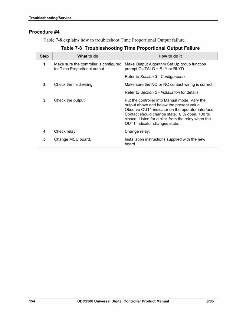
Troubleshooting/Service
154 UDC2500 Universal Digital Controller Product Manual 8/05
Procedure #4 Table 7-8 explains how to troubleshoot Time Proportional Output failure.
Table 7-8 Troubleshooting Time Proportional Output Failure Step What to do How to do it
1 Make sure the controller is configured for Time Proportional output.
Make Output Algorithm Set Up group function prompt OUTALG = RLY or RLYD.
Refer to Section 3 - Configuration.
2 Check the field wiring. Make sure the NO or NC contact wiring is correct.
Refer to Section 2 - Installation for details.
3 Check the output. Put the controller into Manual mode. Vary the output above and below the present value. Observe OUT1 indicator on the operator interface. Contact should change state. 0 % open, 100 % closed. Listen for a click from the relay when the OUT1 indicator changes state.
4 Check relay. Change relay.
5 Change MCU board. Installation instructions supplied with the new board.
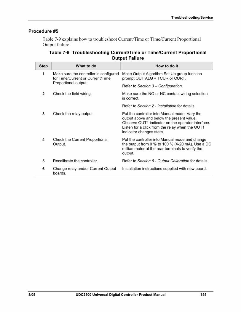
Troubleshooting/Service
8/05 UDC2500 Universal Digital Controller Product Manual 155
Procedure #5 Table 7-9 explains how to troubleshoot Current/Time or Time/Current Proportional Output failure.
Table 7-9 Troubleshooting Current/Time or Time/Current Proportional Output Failure
Step What to do How to do it
1 Make sure the controller is configured for Time/Current or Current/Time Proportional output.
Make Output Algorithm Set Up group function prompt OUT ALG = TCUR or CURT.
Refer to Section 3 – Configuration.
2 Check the field wiring. Make sure the NO or NC contact wiring selection is correct.
Refer to Section 2 - Installation for details.
3 Check the relay output. Put the controller into Manual mode. Vary the output above and below the present value. Observe OUT1 indicator on the operator interface. Listen for a click from the relay when the OUT1 indicator changes state.
4 Check the Current Proportional Output.
Put the controller into Manual mode and change the output from 0 % to 100 % (4-20 mA). Use a DC milliammeter at the rear terminals to verify the output.
5 Recalibrate the controller. Refer to Section 6 - Output Calibration for details.
6 Change relay and/or Current Output boards.
Installation instructions supplied with new board.
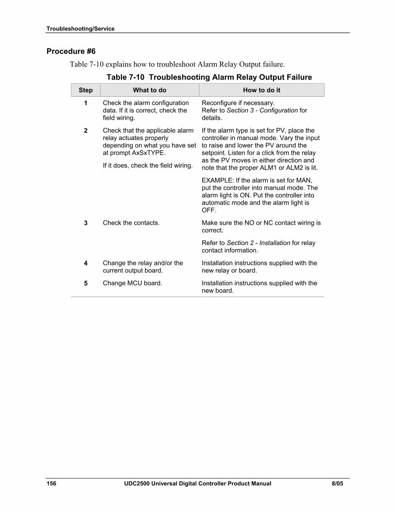
Troubleshooting/Service
156 UDC2500 Universal Digital Controller Product Manual 8/05
Procedure #6 Table 7-10 explains how to troubleshoot Alarm Relay Output failure.
Table 7-10 Troubleshooting Alarm Relay Output Failure Step What to do How to do it
1 Check the alarm configuration data. If it is correct, check the field wiring.
Reconfigure if necessary. Refer to Section 3 - Configuration for details.
2 Check that the applicable alarm relay actuates properly depending on what you have set at prompt AxSxTYPE.
If it does, check the field wiring.
If the alarm type is set for PV, place the controller in manual mode. Vary the input to raise and lower the PV around the setpoint. Listen for a click from the relay as the PV moves in either direction and note that the proper ALM1 or ALM2 is lit.
EXAMPLE: If the alarm is set for MAN, put the controller into manual mode. The alarm light is ON. Put the controller into automatic mode and the alarm light is OFF.
3 Check the contacts. Make sure the NO or NC contact wiring is correct.
Refer to Section 2 - Installation for relay contact information.
4 Change the relay and/or the current output board.
Installation instructions supplied with the new relay or board.
5 Change MCU board. Installation instructions supplied with the new board.
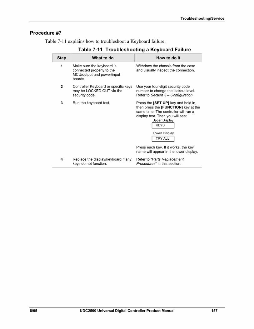
Troubleshooting/Service
8/05 UDC2500 Universal Digital Controller Product Manual 157
Procedure #7 Table 7-11 explains how to troubleshoot a Keyboard failure.
Table 7-11 Troubleshooting a Keyboard Failure Step What to do How to do it
1 Make sure the keyboard is connected properly to the MCU/output and power/input boards.
Withdraw the chassis from the case and visually inspect the connection.
2 Controller Keyboard or specific keys may be LOCKED OUT via the security code.
Use your four-digit security code number to change the lockout level. Refer to Section 3 – Configuration.
3 Run the keyboard test. Press the [SET UP] key and hold in, then press the [FUNCTION] key at the same time. The controller will run a display test. Then you will see:
TRY ALLLower Display
KEYSUpper Display
Press each key. If it works, the key name will appear in the lower display.
4 Replace the display/keyboard if any keys do not function.
Refer to “Parts Replacement Procedures” in this section.
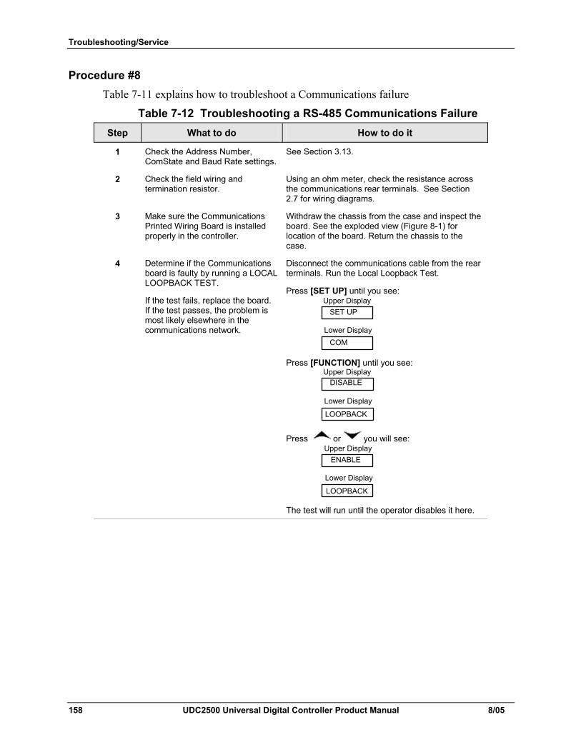
Troubleshooting/Service
158 UDC2500 Universal Digital Controller Product Manual 8/05
Procedure #8 Table 7-11 explains how to troubleshoot a Communications failure
Table 7-12 Troubleshooting a RS-485 Communications Failure Step What to do How to do it
1 Check the Address Number, ComState and Baud Rate settings.
See Section 3.13.
2 Check the field wiring and termination resistor.
Using an ohm meter, check the resistance across the communications rear terminals. See Section 2.7 for wiring diagrams.
3 Make sure the Communications Printed Wiring Board is installed properly in the controller.
Withdraw the chassis from the case and inspect the board. See the exploded view (Figure 8-1) for location of the board. Return the chassis to the case.
4 Determine if the Communications board is faulty by running a LOCAL LOOPBACK TEST.
If the test fails, replace the board. If the test passes, the problem is most likely elsewhere in the communications network.
Disconnect the communications cable from the rear terminals. Run the Local Loopback Test.
Press [SET UP] until you see:
COMLower Display
SET UPUpper Display
Press [FUNCTION] until you see:
LOOPBACK
Lower Display
DISABLEUpper Display
Press or you will see:
LOOPBACK
Lower Display
ENABLEUpper Display
The test will run until the operator disables it here.
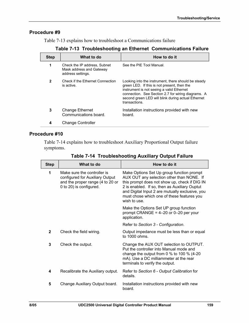
Troubleshooting/Service
8/05 UDC2500 Universal Digital Controller Product Manual 159
Procedure #9 Table 7-13 explains how to troubleshoot a Communications failure
Table 7-13 Troubleshooting an Ethernet Communications Failure Step What to do How to do it
1 Check the IP address, Subnet Mask address and Gateway address settings.
See the PIE Tool Manual.
2 Check if the Ethernet Connection is active.
Looking into the instrument, there should be steady green LED. If this is not present, then the instrument is not seeing a valid Ethernet connection. See Section 2.7 for wiring diagrams. A second green LED will blink during actual Ethernet transactions.
3 Change Ethernet Communications board.
Installation instructions provided with new board.
4 Change Controller
Procedure #10 Table 7-14 explains how to troubleshoot Auxiliary Proportional Output failure symptoms.
Table 7-14 Troubleshooting Auxiliary Output Failure Step What to do How to do it
1 Make sure the controller is configured for Auxiliary Output and the proper range (4 to 20 or 0 to 20) is configured.
Make Options Set Up group function prompt AUX OUT any selection other than NONE. If this prompt does not show up, check if DIG IN 2 is enabled. If so, then as Auxiliary Ouptut and Digital Input 2 are mutually exclusive, you must chose which one of these features you wish to use.
Make the Options Set UP group function prompt CRANGE = 4–20 or 0–20 per your application.
Refer to Section 3 - Configuration.
2 Check the field wiring. Output impedance must be less than or equal to 1000 ohms.
3 Check the output. Change the AUX OUT selection to OUTPUT. Put the controller into Manual mode and change the output from 0 % to 100 % (4-20 mA). Use a DC milliammeter at the rear terminals to verify the output.
4 Recalibrate the Auxiliary output. Refer to Section 6 - Output Calibration for details.
5 Change Auxiliary Output board. Installation instructions provided with new board.
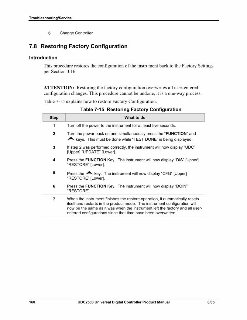
Troubleshooting/Service
160 UDC2500 Universal Digital Controller Product Manual 8/05
6 Change Controller
7.8 Restoring Factory Configuration
Introduction This procedure restores the configuration of the instrument back to the Factory Settings per Section 3.16.
ATTENTION: Restoring the factory configuration overwrites all user-entered configuration changes. This procedure cannot be undone, it is a one-way process.
Table 7-15 explains how to restore Factory Configuration.
Table 7-15 Restoring Factory Configuration Step What to do
1 Turn off the power to the instrument for at least five seconds.
2 Turn the power back on and simultaneously press the “FUNCTION” and keys. This must be done while “TEST DONE” is being displayed.
3 If step 2 was performed correctly, the instrument will now display “UDC” [Upper] “UPDATE” [Lower].
4 Press the FUNCTION Key. The instrument will now display “DIS” [Upper] “RESTORE” [Lower].
5 Press the key. The instrument will now display “CFG” [Upper] “RESTORE” [Lower].
6 Press the FUNCTION Key. The instrument will now display “DOIN” “RESTORE”
7 When the instrument finishes the restore operation, it automatically resets itself and restarts in the product mode. The instrument configuration will now be the same as it was when the instrument left the factory and all user-entered configurations since that time have been overwritten.
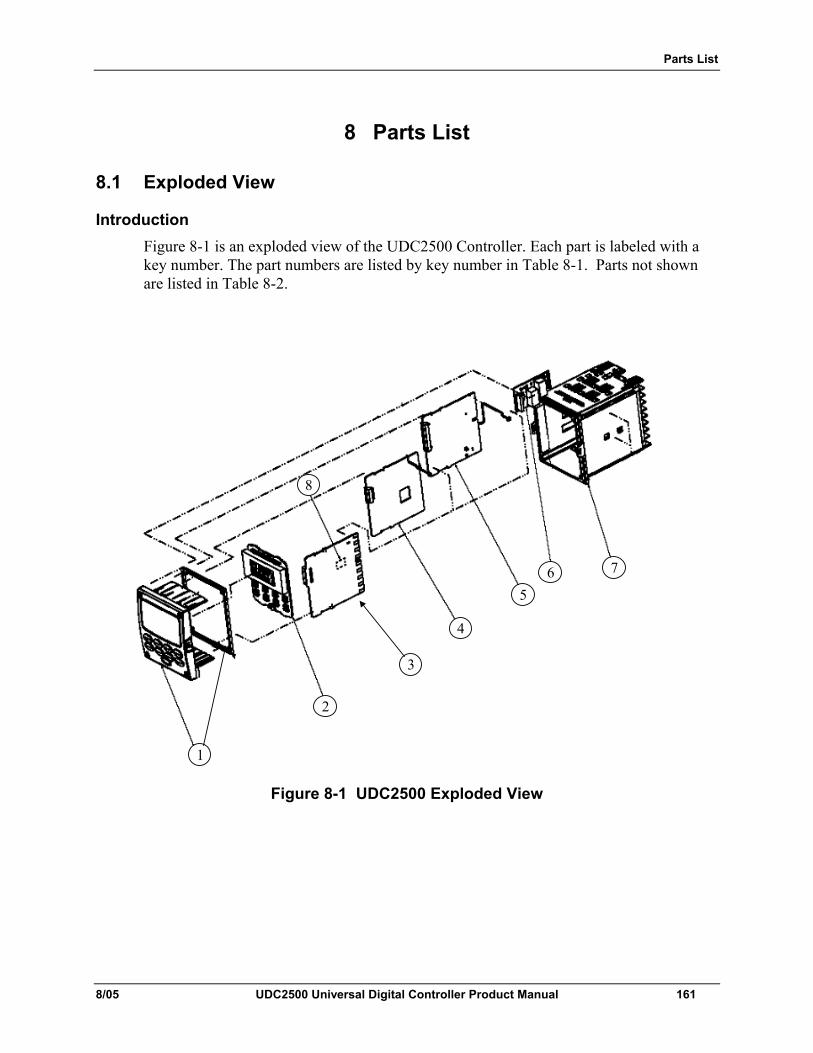
Parts List
8/05 UDC2500 Universal Digital Controller Product Manual 161
8 Parts List
8.1 Exploded View
Introduction Figure 8-1 is an exploded view of the UDC2500 Controller. Each part is labeled with a key number. The part numbers are listed by key number in Table 8-1. Parts not shown are listed in Table 8-2.
4
1
2
3
56 7
8
Figure 8-1 UDC2500 Exploded View
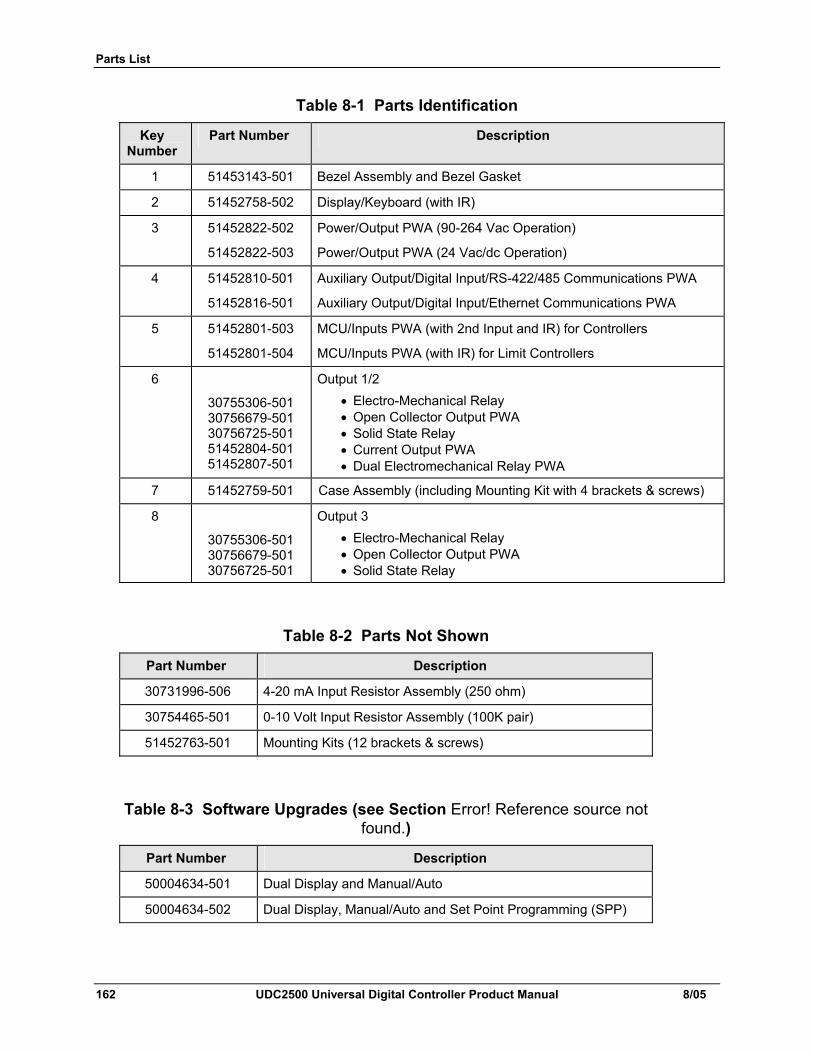
Parts List
162 UDC2500 Universal Digital Controller Product Manual 8/05
Table 8-1 Parts Identification
Key Number
Part Number Description
1 51453143-501 Bezel Assembly and Bezel Gasket
2 51452758-502 Display/Keyboard (with IR)
3 51452822-502
51452822-503
Power/Output PWA (90-264 Vac Operation)
Power/Output PWA (24 Vac/dc Operation)
4 51452810-501
51452816-501
Auxiliary Output/Digital Input/RS-422/485 Communications PWA
Auxiliary Output/Digital Input/Ethernet Communications PWA
5 51452801-503
51452801-504
MCU/Inputs PWA (with 2nd Input and IR) for Controllers
MCU/Inputs PWA (with IR) for Limit Controllers
6 30755306-501 30756679-501 30756725-501 51452804-501 51452807-501
Output 1/2 • Electro-Mechanical Relay • Open Collector Output PWA • Solid State Relay • Current Output PWA • Dual Electromechanical Relay PWA
7 51452759-501 Case Assembly (including Mounting Kit with 4 brackets & screws)
8 30755306-501 30756679-501 30756725-501
Output 3 • Electro-Mechanical Relay • Open Collector Output PWA • Solid State Relay
Table 8-2 Parts Not Shown
Part Number Description
30731996-506 4-20 mA Input Resistor Assembly (250 ohm)
30754465-501 0-10 Volt Input Resistor Assembly (100K pair)
51452763-501 Mounting Kits (12 brackets & screws)
Table 8-3 Software Upgrades (see Section Error! Reference source not found.)
Part Number Description
50004634-501 Dual Display and Manual/Auto
50004634-502 Dual Display, Manual/Auto and Set Point Programming (SPP)
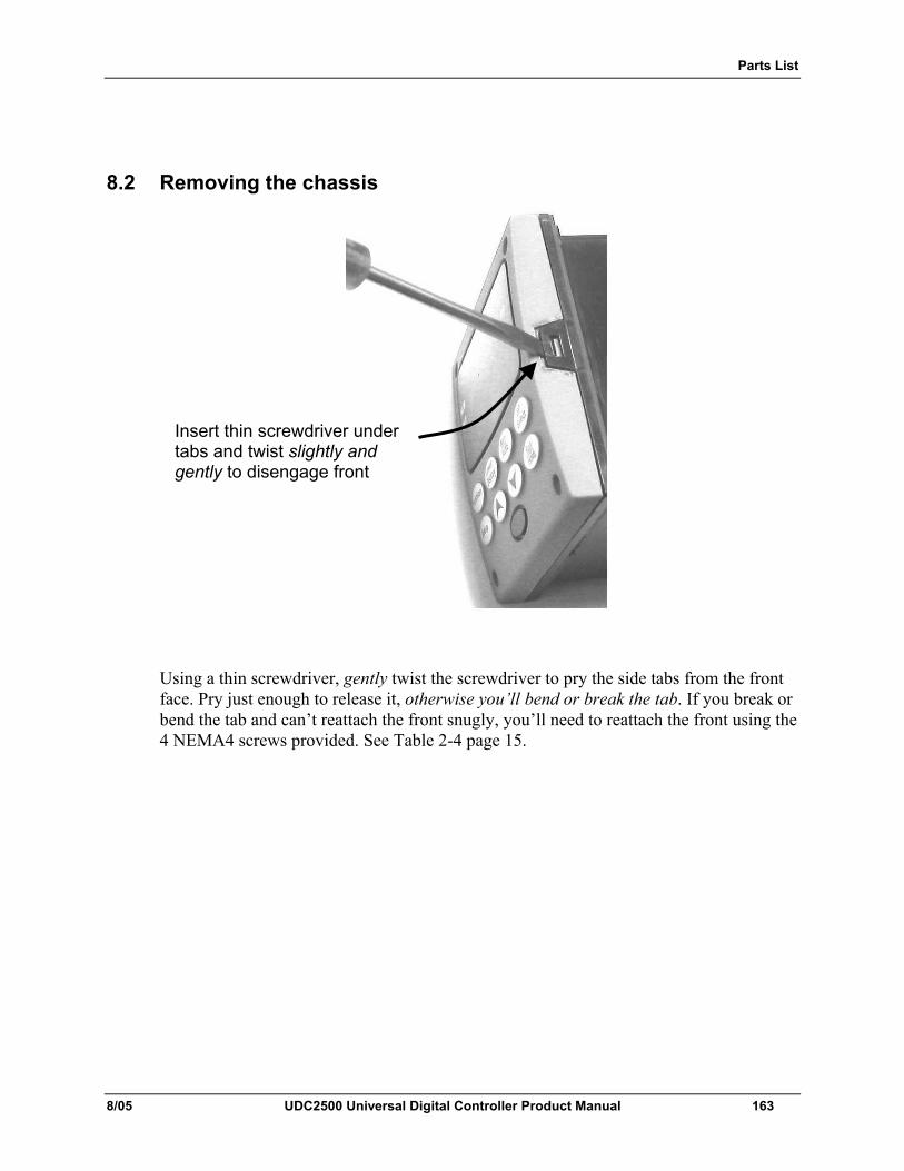
Parts List
8/05 UDC2500 Universal Digital Controller Product Manual 163
8.2 Removing the chassis
Using a thin screwdriver, gently twist the screwdriver to pry the side tabs from the front face. Pry just enough to release it, otherwise you’ll bend or break the tab. If you break or bend the tab and can’t reattach the front snugly, you’ll need to reattach the front using the 4 NEMA4 screws provided. See Table 2-4 page 15.
Insert thin screwdriver under tabs and twist slightly and gently to disengage front
Modbus RTU Function Codes
164 UDC2500 Universal Digital Controller Product Manual 8/05
9 Modbus RTU Function Codes
9.1 Overview This section describes the function codes needed to upload and download the configuration from a host computer into this instrument.
What's in this section? The following topics are covered in this section.
TOPIC See Page
9.1 Overview 164
9.2 General Information 164
9.3 Function Code 20 166
9.4 Function Code 21 170
9.2 General Information This instrument uses a subset of the standard Modbus RTU function codes to provide access to process-related information. Several MODICON function codes are implemented. It is appropriate to define instrument-specific "user-defined" function codes. Where differences occur between the two protocols it will be noted. Several standard Modbus RTU function codes are supported.
Configuration ID Tags Function codes 20 and 21 use the RS422/485 tag IDs for accessing configuration and process-related data. These tags are fully explained in Section 10.
The tag IDs represent the register addresses used in the Request Message.
Other Modbus Codes For Modbus codes other than for accessing configuration and process-related data for this controller, refer to the Modbus RTU Serial Communications User Manual # 51-55-25-66M.
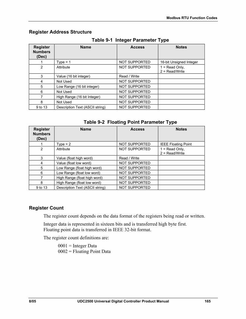
Modbus RTU Function Codes
8/05 UDC2500 Universal Digital Controller Product Manual 165
Register Address Structure Table 9-1 Integer Parameter Type
Register Numbers
(Dec)
Name Access Notes
1 Type = 1 NOT SUPPORTED 16-bit Unsigned Integer 2 Attribute NOT SUPPORTED 1 = Read Only,
2 = Read/Write 3 Value (16 bit integer) Read / Write 4 Not Used NOT SUPPORTED 5 Low Range (16 bit integer) NOT SUPPORTED 6 Not Used NOT SUPPORTED 7 High Range (16 bit Integer) NOT SUPPORTED 8 Not Used NOT SUPPORTED
9 to 13 Description Text (ASCII string) NOT SUPPORTED
Table 9-2 Floating Point Parameter Type
Register Numbers
(Dec)
Name Access Notes
1 Type = 2 NOT SUPPORTED IEEE Floating Point 2 Attribute NOT SUPPORTED 1 = Read Only,
2 = Read/Write 3 Value (float high word) Read / Write 4 Value (float low word) NOT SUPPORTED 5 Low Range (float high word) NOT SUPPORTED 6 Low Range (float low word) NOT SUPPORTED 7 High Range (float high word) NOT SUPPORTED 8 High Range (float low word) NOT SUPPORTED
9 to 13 Description Text (ASCII string) NOT SUPPORTED
Register Count The register count depends on the data format of the registers being read or written.
Integer data is represented in sixteen bits and is transferred high byte first. Floating point data is transferred in IEEE 32-bit format.
The register count definitions are:
0001 = Integer Data 0002 = Floating Point Data
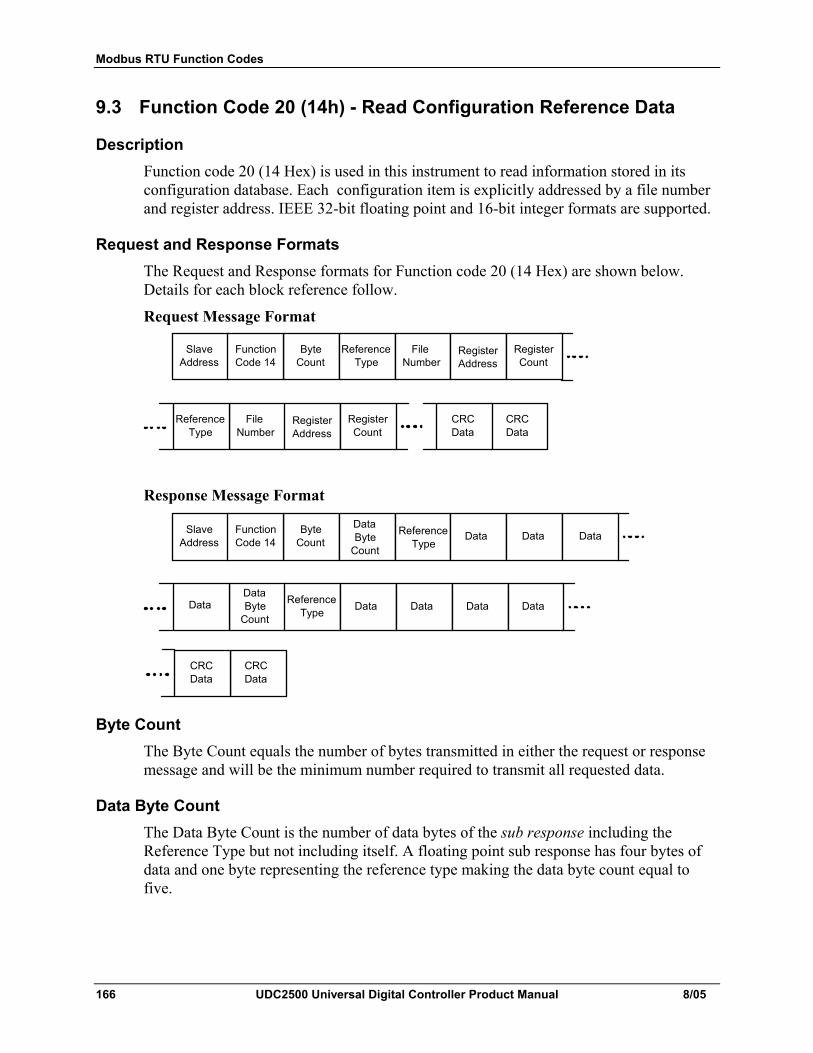
Modbus RTU Function Codes
166 UDC2500 Universal Digital Controller Product Manual 8/05
9.3 Function Code 20 (14h) - Read Configuration Reference Data
Description Function code 20 (14 Hex) is used in this instrument to read information stored in its configuration database. Each configuration item is explicitly addressed by a file number and register address. IEEE 32-bit floating point and 16-bit integer formats are supported.
Request and Response Formats The Request and Response formats for Function code 20 (14 Hex) are shown below. Details for each block reference follow.
Request Message Format
Slave Address
Byte Count
Reference Type
Function Code 14
Reference Type
File Number
Register Count
Register Address
Reference Type
File Number
Register Count
Register Address
CRC Data
CRC Data
Response Message Format
Slave Address
Byte Count
Reference Type
Function Code 14
Reference Type
Data
Reference Type
Data Byte
CountData Data
DataData Byte
CountData Data Data Data
CRC Data
CRC Data
Byte Count The Byte Count equals the number of bytes transmitted in either the request or response message and will be the minimum number required to transmit all requested data.
Data Byte Count The Data Byte Count is the number of data bytes of the sub response including the Reference Type but not including itself. A floating point sub response has four bytes of data and one byte representing the reference type making the data byte count equal to five.
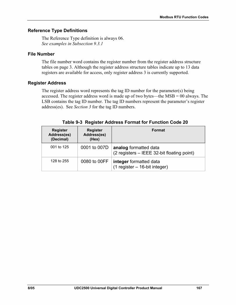
Modbus RTU Function Codes
8/05 UDC2500 Universal Digital Controller Product Manual 167
Reference Type Definitions The Reference Type definition is always 06. See examples in Subsection 9.3.1
File Number The file number word contains the register number from the register address structure tables on page 3. Although the register address structure tables indicate up to 13 data registers are available for access, only register address 3 is currently supported.
Register Address The register address word represents the tag ID number for the parameter(s) being accessed. The register address word is made up of two bytes—the MSB = 00 always. The LSB contains the tag ID number. The tag ID numbers represent the parameter’s register address(es). See Section 3 for the tag ID numbers.
Table 9-3 Register Address Format for Function Code 20 Register
Address(es) (Decimal)
Register Address(es)
(Hex)
Format
001 to 125 0001 to 007D analog formatted data (2 registers – IEEE 32-bit floating point)
128 to 255 0080 to 00FF integer formatted data (1 register – 16-bit integer)
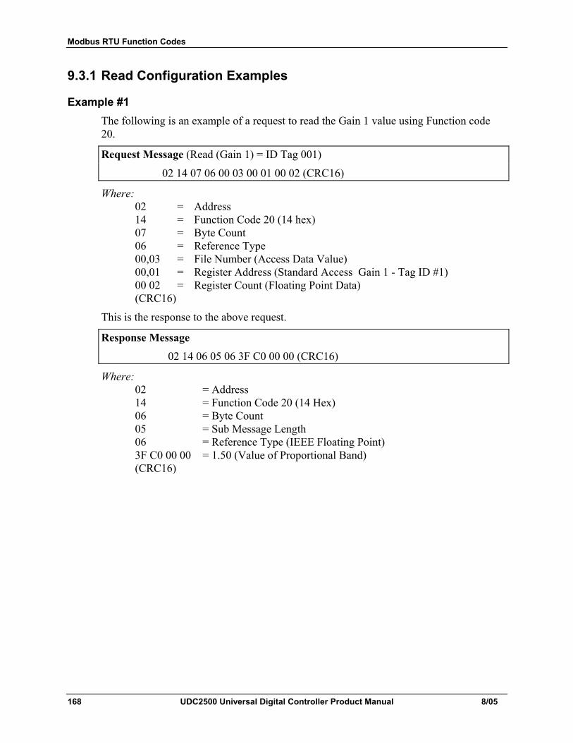
Modbus RTU Function Codes
168 UDC2500 Universal Digital Controller Product Manual 8/05
9.3.1 Read Configuration Examples
Example #1 The following is an example of a request to read the Gain 1 value using Function code 20.
Request Message (Read (Gain 1) = ID Tag 001)
02 14 07 06 00 03 00 01 00 02 (CRC16)
Where: 02 = Address 14 = Function Code 20 (14 hex) 07 = Byte Count 06 = Reference Type 00,03 = File Number (Access Data Value) 00,01 = Register Address (Standard Access Gain 1 - Tag ID #1) 00 02 = Register Count (Floating Point Data) (CRC16)
This is the response to the above request.
Response Message
02 14 06 05 06 3F C0 00 00 (CRC16)
Where: 02 = Address 14 = Function Code 20 (14 Hex) 06 = Byte Count 05 = Sub Message Length 06 = Reference Type (IEEE Floating Point) 3F C0 00 00 = 1.50 (Value of Proportional Band) (CRC16)
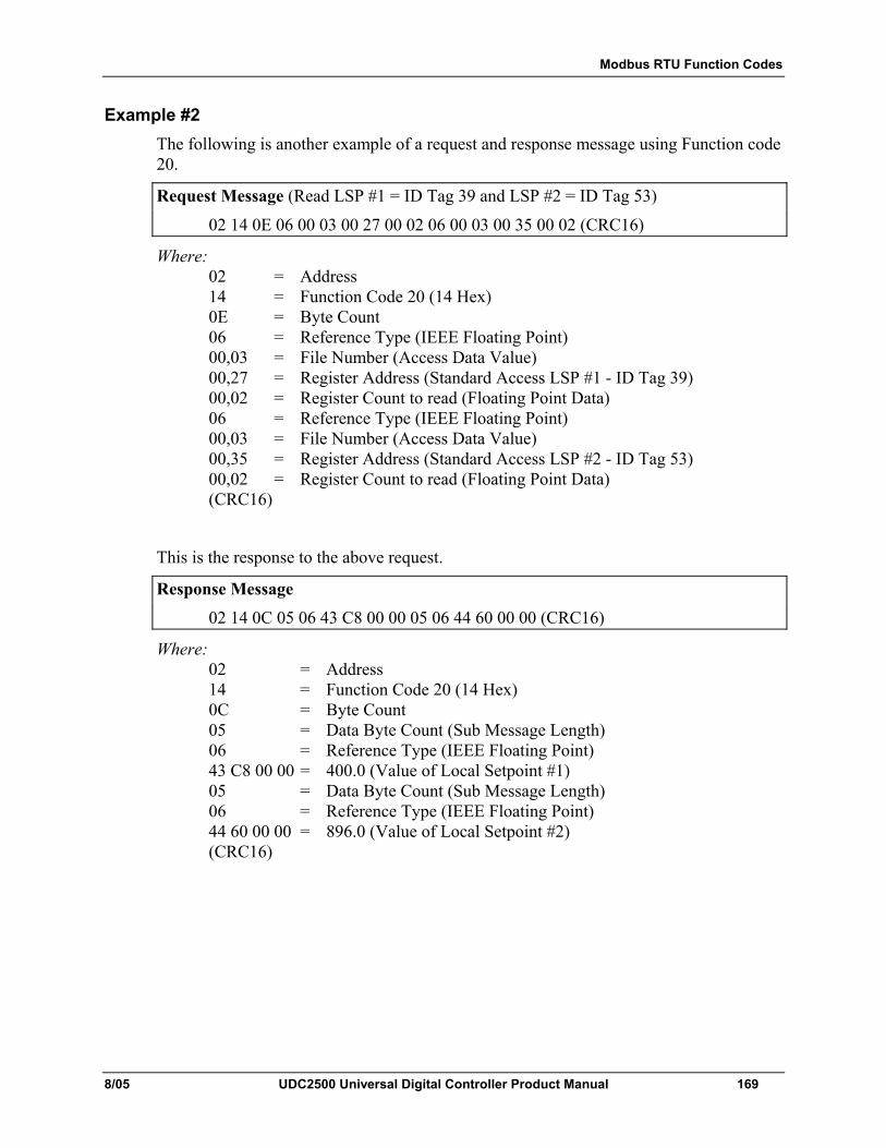
Modbus RTU Function Codes
8/05 UDC2500 Universal Digital Controller Product Manual 169
Example #2 The following is another example of a request and response message using Function code 20.
Request Message (Read LSP #1 = ID Tag 39 and LSP #2 = ID Tag 53)
02 14 0E 06 00 03 00 27 00 02 06 00 03 00 35 00 02 (CRC16)
Where: 02 = Address 14 = Function Code 20 (14 Hex) 0E = Byte Count 06 = Reference Type (IEEE Floating Point) 00,03 = File Number (Access Data Value) 00,27 = Register Address (Standard Access LSP #1 - ID Tag 39) 00,02 = Register Count to read (Floating Point Data) 06 = Reference Type (IEEE Floating Point) 00,03 = File Number (Access Data Value) 00,35 = Register Address (Standard Access LSP #2 - ID Tag 53) 00,02 = Register Count to read (Floating Point Data) (CRC16)
This is the response to the above request.
Response Message
02 14 0C 05 06 43 C8 00 00 05 06 44 60 00 00 (CRC16)
Where: 02 = Address 14 = Function Code 20 (14 Hex) 0C = Byte Count 05 = Data Byte Count (Sub Message Length) 06 = Reference Type (IEEE Floating Point) 43 C8 00 00 = 400.0 (Value of Local Setpoint #1) 05 = Data Byte Count (Sub Message Length) 06 = Reference Type (IEEE Floating Point) 44 60 00 00 = 896.0 (Value of Local Setpoint #2) (CRC16)
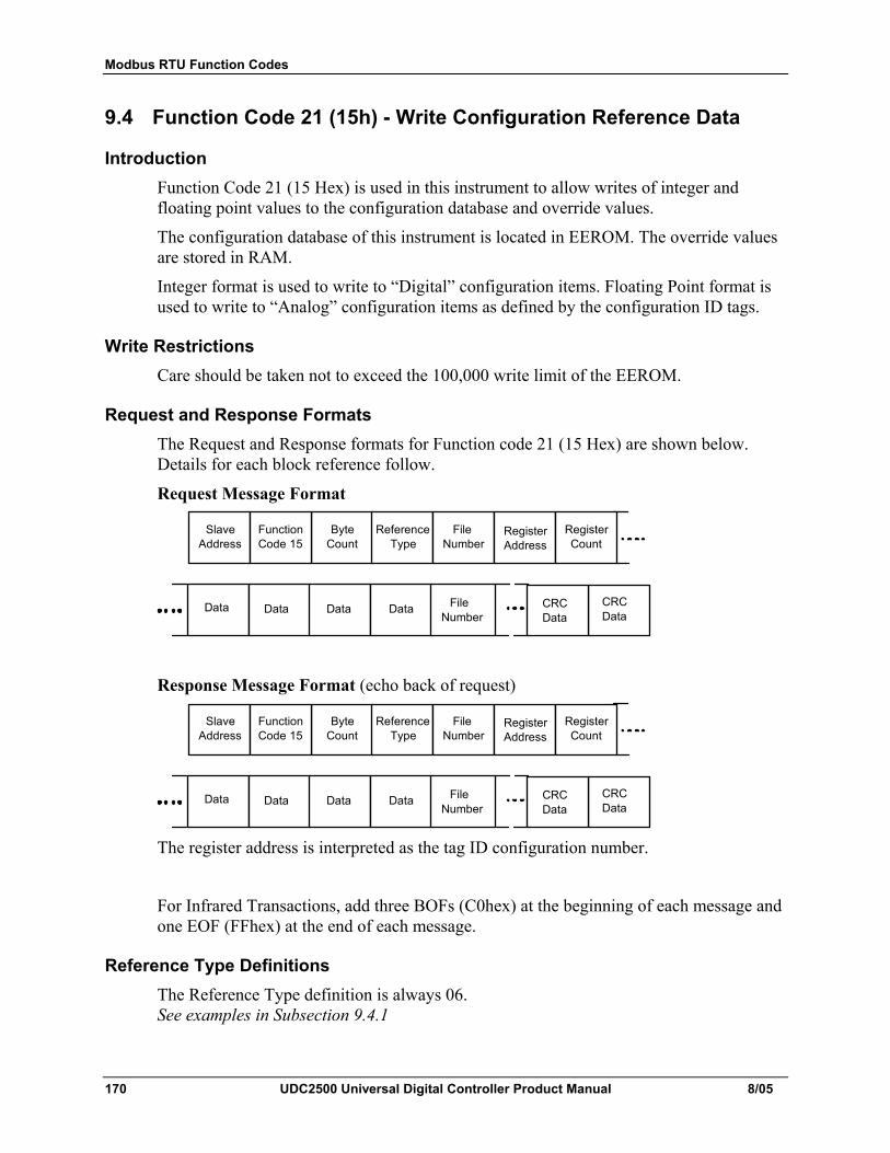
Modbus RTU Function Codes
170 UDC2500 Universal Digital Controller Product Manual 8/05
9.4 Function Code 21 (15h) - Write Configuration Reference Data
Introduction Function Code 21 (15 Hex) is used in this instrument to allow writes of integer and floating point values to the configuration database and override values.
The configuration database of this instrument is located in EEROM. The override values are stored in RAM.
Integer format is used to write to “Digital” configuration items. Floating Point format is used to write to “Analog” configuration items as defined by the configuration ID tags.
Write Restrictions Care should be taken not to exceed the 100,000 write limit of the EEROM.
Request and Response Formats The Request and Response formats for Function code 21 (15 Hex) are shown below. Details for each block reference follow.
Request Message Format
Slave Address
Byte Count
Function Code 15
Reference Type
File Number
Register Count
Register Address
CRC Data
CRC Data
Data Data Data Data File Number
Response Message Format (echo back of request)
Slave Address
Byte Count
Function Code 15
Reference Type
File Number
Register Count
Register Address
CRC Data
CRC Data
Data Data Data Data File Number
The register address is interpreted as the tag ID configuration number.
For Infrared Transactions, add three BOFs (C0hex) at the beginning of each message and one EOF (FFhex) at the end of each message.
Reference Type Definitions The Reference Type definition is always 06. See examples in Subsection 9.4.1
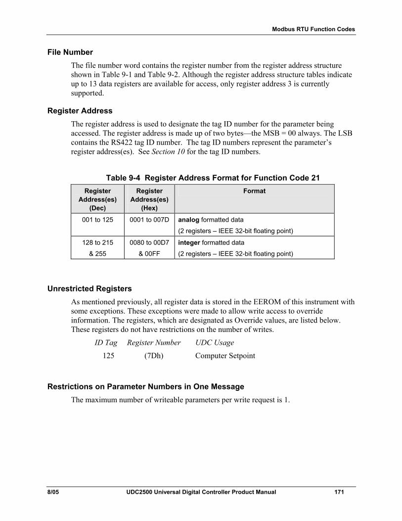
Modbus RTU Function Codes
8/05 UDC2500 Universal Digital Controller Product Manual 171
File Number The file number word contains the register number from the register address structure shown in Table 9-1 and Table 9-2. Although the register address structure tables indicate up to 13 data registers are available for access, only register address 3 is currently supported.
Register Address The register address is used to designate the tag ID number for the parameter being accessed. The register address is made up of two bytes—the MSB = 00 always. The LSB contains the RS422 tag ID number. The tag ID numbers represent the parameter’s register address(es). See Section 10 for the tag ID numbers.
Table 9-4 Register Address Format for Function Code 21 Register
Address(es) (Dec)
Register Address(es)
(Hex)
Format
001 to 125 0001 to 007D analog formatted data
(2 registers – IEEE 32-bit floating point)
128 to 215
& 255
0080 to 00D7
& 00FF
integer formatted data
(2 registers – IEEE 32-bit floating point)
Unrestricted Registers As mentioned previously, all register data is stored in the EEROM of this instrument with some exceptions. These exceptions were made to allow write access to override information. The registers, which are designated as Override values, are listed below. These registers do not have restrictions on the number of writes.
ID Tag Register Number UDC Usage
125 (7Dh) Computer Setpoint
Restrictions on Parameter Numbers in One Message The maximum number of writeable parameters per write request is 1.

Modbus RTU Function Codes
172 UDC2500 Universal Digital Controller Product Manual 8/05
9.4.1 Write Configuration Examples
Example #1 The following is an example of a request to write the Gain 1 value using Function code 21 (15 Hex).
Request Message (Write Gain 1= 1.5 “ID Tag 1”)
02 15 0B 06 00 03 00 01 00 02 3F C0 00 00 (CRC16)
Where: 02 = Address 15 = Function Code 21 (15 Hex) 0B = Byte Count 06 = Reference Type (IEEE Floating Point) 00 03 = File Number (Access Data Value) 00 01 = Register Address (Standard Access - Gain 1 - ID Tag 1) 00 02 = Register Count (Floating Point Data) 3F C0 00 00 = 1.50 (CRC16)
This is the response to the above request.
Response Message (The response is an echo of the request)
02 15 0B 06 00 01 00 02 00 02 3F C0 00 00 (CRC16)
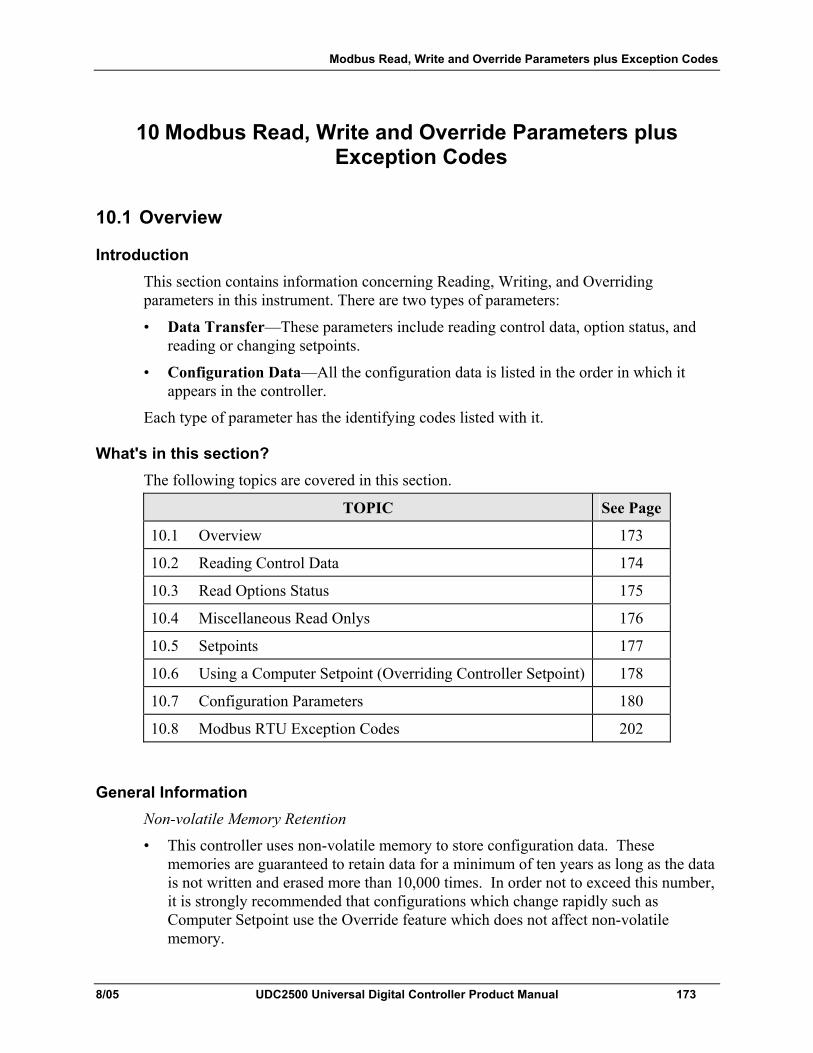
Modbus Read, Write and Override Parameters plus Exception Codes
8/05 UDC2500 Universal Digital Controller Product Manual 173
10 Modbus Read, Write and Override Parameters plus Exception Codes
10.1 Overview
Introduction This section contains information concerning Reading, Writing, and Overriding parameters in this instrument. There are two types of parameters:
• Data Transfer—These parameters include reading control data, option status, and reading or changing setpoints.
• Configuration Data—All the configuration data is listed in the order in which it appears in the controller.
Each type of parameter has the identifying codes listed with it.
What's in this section? The following topics are covered in this section.
TOPIC See Page
10.1 Overview 173
10.2 Reading Control Data 174
10.3 Read Options Status 175
10.4 Miscellaneous Read Onlys 176
10.5 Setpoints 177
10.6 Using a Computer Setpoint (Overriding Controller Setpoint) 178
10.7 Configuration Parameters 180
10.8 Modbus RTU Exception Codes 202
General Information Non-volatile Memory Retention
• This controller uses non-volatile memory to store configuration data. These memories are guaranteed to retain data for a minimum of ten years as long as the data is not written and erased more than 10,000 times. In order not to exceed this number, it is strongly recommended that configurations which change rapidly such as Computer Setpoint use the Override feature which does not affect non-volatile memory.
Modbus Read, Write and Override Parameters plus Exception Codes
174 UDC2500 Universal Digital Controller Product Manual 8/05
Analog Parameters
• Whenever analog register addresses 0001 through 0074 (those that can be changed via communications) are changed, a Write cycle occurs after receipt of the message and the response is returned.
Override Parameters
• Override analog register address 007D (computer setpoint) is not stored in non-volatile memory. It can be changed as frequently as desired with no effect on non-volatile memory retentivity, but the controller must remain in the slave mode.
Digital Parameters
• Whenever digital configuration register addresses 0080 through 00FA are updated via communications, the non-volatile memory is updated as soon as the message is received.
Communications Transfer Rates
• Reads minimum 20mS and writes minimum 200mS
Supported Function Codes
• IR port 20 and 21
• RS485 and Ethernet ports 1,2,3,4,6,16,17,20,21
Communications Modes of Operation
• When the Shed Timer is enabled and a write or override occurs the controller will enter Slave Mode. The keypad is locked from the operator. The purpose of this mode is that if communications is lost and the shed timer times out then the controller will enter a known state of operation. The configuration of the “Shed Mode and Output” and Shed Setpoint Recall are used to configure the controller’s shed state. While in Slave Mode pushing the MAN/AUTO key enters Emergency Manual mode. The local operator then has control of the output. The controller is in Monitor Mode if the Shed timer is disabled.
10.2 Reading Control Data
Overview The following control data can be read from this instrument:
• Input 1 • Input 2 • PV, SP, Output
Register Addresses Use the identifying codes listed in Table 10-1 to read the specific items.
A Write request for these codes will result in an Error message.
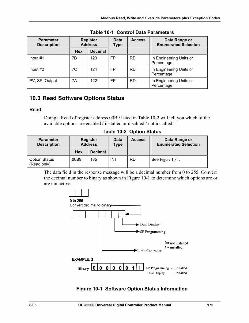
Modbus Read, Write and Override Parameters plus Exception Codes
8/05 UDC2500 Universal Digital Controller Product Manual 175
Table 10-1 Control Data Parameters Parameter
Description Register Address
Data Type
Access Data Range or Enumerated Selection
Hex Decimal Input #1 7B 123 FP RD In Engineering Units or
Percentage Input #2 7C 124 FP RD In Engineering Units or
Percentage PV, SP, Output 7A 122 FP RD In Engineering Units or
Percentage
10.3 Read Software Options Status
Read Doing a Read of register address 00B9 listed in Table 10-2 will tell you which of the available options are enabled / installed or disabled / not installed.
Table 10-2 Option Status Parameter
Description Register Address
Data Type
Access Data Range or Enumerated Selection
Hex Decimal
Option Status (Read only)
00B9 185 INT RD See Figure 10-1.
The data field in the response message will be a decimal number from 0 to 255. Convert the decimal number to binary as shown in Figure 10-1.to determine which options are or are not active.
0 to 255 Convert decimal to binary
0 = not installed 1 = installed
EXAMPLE: 3
Binary SP Programming – installed 0 0 0 0 0 1 1 0 Dual Display – installed
SP Programming
0 to 255 Convert decimal to binary
0 = not installed 1 = installed
EXAMPLE:
Binary SP Programming – installed 0 0 0 0 0 1 1 0 – installed
EXAMPLE:
Binary SP Programming – installed 0 0 0 0 0 0 1 1 – installed
SP Programming
Dual Display
Limit Controller
Figure 10-1 Software Option Status Information
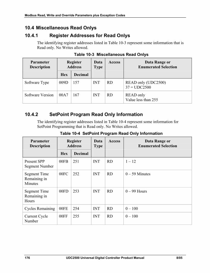
Modbus Read, Write and Override Parameters plus Exception Codes
176 UDC2500 Universal Digital Controller Product Manual 8/05
10.4 Miscellaneous Read Onlys 10.4.1 Register Addresses for Read Onlys
The identifying register addresses listed in Table 10-3 represent some information that is Read only. No Writes allowed.
Table 10-3 Miscellaneous Read Onlys
Parameter Description
Register Address
Data Type
Access Data Range or Enumerated Selection
Hex Decimal
Software Type 009D 157 INT RD READ only (UDC2500) 37 = UDC2500
Software Version 00A7 167 INT RD READ only Value less than 255
10.4.2 SetPoint Program Read Only Information The identifying register addresses listed in Table 10-4 represent some information for SetPoint Programming that is Read only. No Writes allowed.
Table 10-4 SetPoint Program Read Only Information
Parameter Description
Register Address
Data Type
Access Data Range or Enumerated Selection
Hex Decimal
Present SPP Segment Number
00FB 251 INT RD 1 – 12
Segment Time Remaining in Minutes
00FC 252 INT RD 0 – 59 Minutes
Segment Time Remaining in Hours
00FD 253 INT RD 0 – 99 Hours
Cycles Remaining 00FE 254 INT RD 0 – 100
Current Cycle Number
00FF 255 INT RD 0 – 100
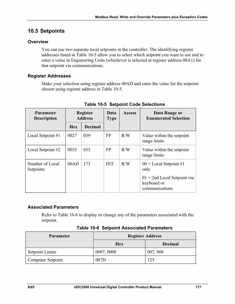
Modbus Read, Write and Override Parameters plus Exception Codes
8/05 UDC2500 Universal Digital Controller Product Manual 177
10.5 Setpoints
Overview You can use two separate local setpoints in the controller. The identifying register addresses listed in Table 10-5 allow you to select which setpoint you want to use and to enter a value in Engineering Units (whichever is selected at register address 00A1) for that setpoint via communications.
Register Addresses Make your selection using register address 00AD and enter the value for the setpoint chosen using register address in Table 10-5.
Table 10-5 Setpoint Code Selections
Parameter Description
Register Address
Data Type
Access Data Range or Enumerated Selection
Hex Decimal
Local Setpoint #1 0027 039 FP R/W Value within the setpoint range limits
Local Setpoint #2 0035 053 FP R/W Value within the setpoint range limits
Number of Local Setpoints
00AD 173 INT R/W 00 = Local Setpoint #1 only
01 = 2nd Local Setpoint via keyboard or communications
Associated Parameters Refer to Table 10-6 to display or change any of the parameters associated with the setpoint.
Table 10-6 Setpoint Associated Parameters
Parameter Register Address
Hex Decimal
Setpoint Limits 0007, 0008 007, 008
Computer Setpoint 007D 125
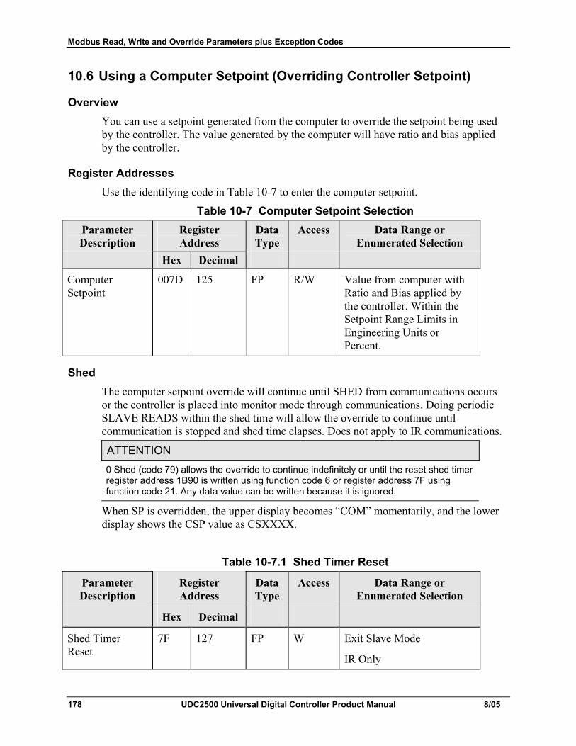
Modbus Read, Write and Override Parameters plus Exception Codes
178 UDC2500 Universal Digital Controller Product Manual 8/05
10.6 Using a Computer Setpoint (Overriding Controller Setpoint)
Overview You can use a setpoint generated from the computer to override the setpoint being used by the controller. The value generated by the computer will have ratio and bias applied by the controller.
Register Addresses Use the identifying code in Table 10-7 to enter the computer setpoint.
Table 10-7 Computer Setpoint Selection Parameter Description
Register Address
Data Type
Access Data Range or Enumerated Selection
Hex Decimal
Computer Setpoint
007D 125 FP R/W Value from computer with Ratio and Bias applied by the controller. Within the Setpoint Range Limits in Engineering Units or Percent.
Shed The computer setpoint override will continue until SHED from communications occurs or the controller is placed into monitor mode through communications. Doing periodic SLAVE READS within the shed time will allow the override to continue until communication is stopped and shed time elapses. Does not apply to IR communications.
ATTENTION 0 Shed (code 79) allows the override to continue indefinitely or until the reset shed timer register address 1B90 is written using function code 6 or register address 7F using function code 21. Any data value can be written because it is ignored.
When SP is overridden, the upper display becomes “COM” momentarily, and the lower display shows the CSP value as CSXXXX.
Table 10-7.1 Shed Timer Reset
Parameter Description
Register Address
Data Type
Access Data Range or Enumerated Selection
Hex Decimal
Shed Timer Reset
7F 127 FP W Exit Slave Mode
IR Only
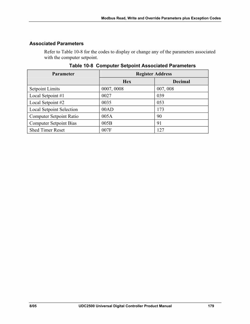
Modbus Read, Write and Override Parameters plus Exception Codes
8/05 UDC2500 Universal Digital Controller Product Manual 179
Associated Parameters Refer to Table 10-8 for the codes to display or change any of the parameters associated with the computer setpoint.
Table 10-8 Computer Setpoint Associated Parameters Parameter Register Address
Hex Decimal Setpoint Limits 0007, 0008 007, 008 Local Setpoint #1 0027 039 Local Setpoint #2 0035 053 Local Setpoint Selection 00AD 173 Computer Setpoint Ratio 005A 90 Computer Setpoint Bias 005B 91 Shed Timer Reset 007F 127
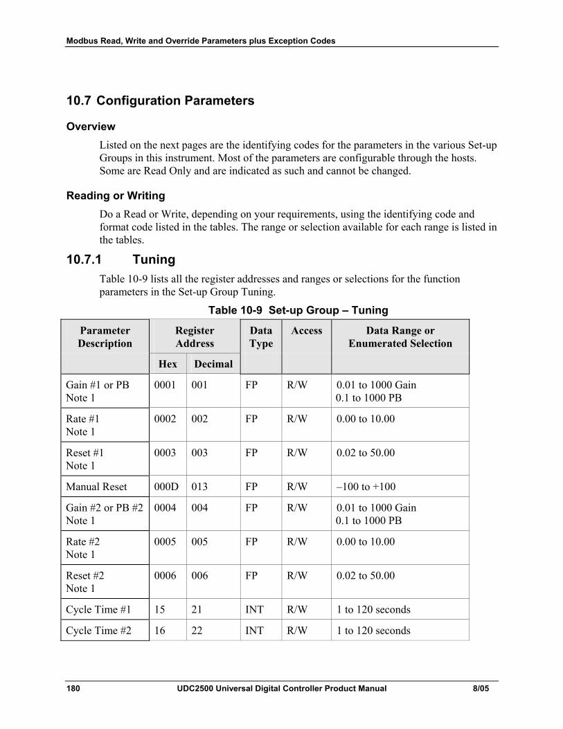
Modbus Read, Write and Override Parameters plus Exception Codes
180 UDC2500 Universal Digital Controller Product Manual 8/05
10.7 Configuration Parameters
Overview Listed on the next pages are the identifying codes for the parameters in the various Set-up Groups in this instrument. Most of the parameters are configurable through the hosts. Some are Read Only and are indicated as such and cannot be changed.
Reading or Writing Do a Read or Write, depending on your requirements, using the identifying code and format code listed in the tables. The range or selection available for each range is listed in the tables.
10.7.1 Tuning Table 10-9 lists all the register addresses and ranges or selections for the function parameters in the Set-up Group Tuning.
Table 10-9 Set-up Group – Tuning
Parameter Description
Register Address
Data Type
Access Data Range or Enumerated Selection
Hex Decimal
Gain #1 or PB Note 1
0001 001 FP R/W 0.01 to 1000 Gain 0.1 to 1000 PB
Rate #1 Note 1
0002 002 FP R/W 0.00 to 10.00
Reset #1 Note 1
0003 003 FP R/W 0.02 to 50.00
Manual Reset 000D 013 FP R/W –100 to +100
Gain #2 or PB #2 Note 1
0004 004 FP R/W 0.01 to 1000 Gain 0.1 to 1000 PB
Rate #2 Note 1
0005 005 FP R/W 0.00 to 10.00
Reset #2 Note 1
0006 006 FP R/W 0.02 to 50.00
Cycle Time #1 15 21 INT R/W 1 to 120 seconds
Cycle Time #2 16 22 INT R/W 1 to 120 seconds
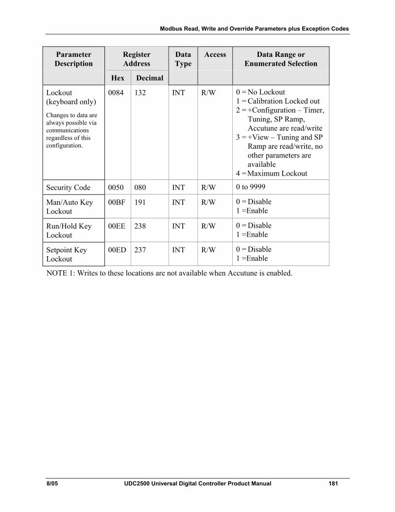
Modbus Read, Write and Override Parameters plus Exception Codes
8/05 UDC2500 Universal Digital Controller Product Manual 181
Parameter Description
Register Address
Data Type
Access Data Range or Enumerated Selection
Hex Decimal
Lockout (keyboard only)
Changes to data are always possible via communications regardless of this configuration.
0084 132 INT R/W 0 = No Lockout 1 = Calibration Locked out 2 = +Configuration – Timer,
Tuning, SP Ramp, Accutune are read/write
3 = +View – Tuning and SP Ramp are read/write, no other parameters are available
4 = Maximum Lockout
Security Code 0050 080 INT R/W 0 to 9999
Man/Auto Key Lockout
00BF 191 INT R/W 0 = Disable 1 =Enable
Run/Hold Key Lockout
00EE 238 INT R/W 0 = Disable 1 =Enable
Setpoint Key Lockout
00ED 237 INT R/W 0 = Disable 1 =Enable
NOTE 1: Writes to these locations are not available when Accutune is enabled.
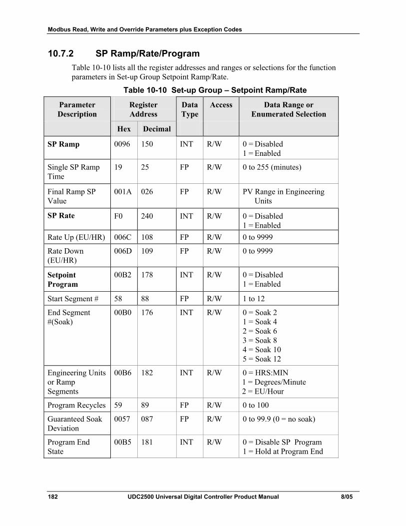
Modbus Read, Write and Override Parameters plus Exception Codes
182 UDC2500 Universal Digital Controller Product Manual 8/05
10.7.2 SP Ramp/Rate/Program Table 10-10 lists all the register addresses and ranges or selections for the function parameters in Set-up Group Setpoint Ramp/Rate.
Table 10-10 Set-up Group – Setpoint Ramp/Rate
Parameter Description
Register Address
Data Type
Access Data Range or Enumerated Selection
Hex Decimal
SP Ramp 0096 150 INT R/W 0 = Disabled 1 = Enabled
Single SP Ramp Time
19 25 FP R/W 0 to 255 (minutes)
Final Ramp SP Value
001A 026 FP R/W PV Range in Engineering Units
SP Rate F0 240 INT R/W 0 = Disabled 1 = Enabled
Rate Up (EU/HR) 006C 108 FP R/W 0 to 9999
Rate Down (EU/HR)
006D 109 FP R/W 0 to 9999
Setpoint Program
00B2 178 INT R/W 0 = Disabled 1 = Enabled
Start Segment # 58 88 FP R/W 1 to 12
End Segment #(Soak)
00B0 176 INT R/W 0 = Soak 2 1 = Soak 4 2 = Soak 6 3 = Soak 8 4 = Soak 10 5 = Soak 12
Engineering Units or Ramp Segments
00B6 182 INT R/W 0 = HRS:MIN 1 = Degrees/Minute 2 = EU/Hour
Program Recycles 59 89 FP R/W 0 to 100
Guaranteed Soak Deviation
0057 087 FP R/W 0 to 99.9 (0 = no soak)
Program End State
00B5 181 INT R/W 0 = Disable SP Program 1 = Hold at Program End
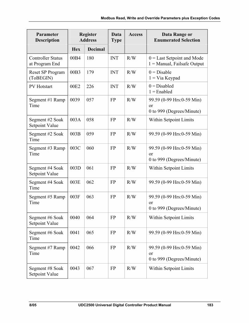
Modbus Read, Write and Override Parameters plus Exception Codes
8/05 UDC2500 Universal Digital Controller Product Manual 183
Parameter Description
Register Address
Data Type
Access Data Range or Enumerated Selection
Hex Decimal
Controller Status at Program End
00B4 180 INT R/W 0 = Last Setpoint and Mode 1 = Manual, Failsafe Output
Reset SP Program (ToBEGIN)
00B3 179 INT R/W 0 = Disable 1 = Via Keypad
PV Hotstart 00E2 226 INT R/W 0 = Disabled 1 = Enabled
Segment #1 Ramp Time
0039 057 FP R/W 99.59 (0-99 Hrs:0-59 Min) or 0 to 999 (Degrees/Minute)
Segment #2 Soak Setpoint Value
003A 058 FP R/W Within Setpoint Limits
Segment #2 Soak Time
003B 059 FP R/W 99.59 (0-99 Hrs:0-59 Min)
Segment #3 Ramp Time
003C 060 FP R/W 99.59 (0-99 Hrs:0-59 Min) or 0 to 999 (Degrees/Minute)
Segment #4 Soak Setpoint Value
003D 061 FP R/W Within Setpoint Limits
Segment #4 Soak Time
003E 062 FP R/W 99.59 (0-99 Hrs:0-59 Min)
Segment #5 Ramp Time
003F 063 FP R/W 99.59 (0-99 Hrs:0-59 Min) or 0 to 999 (Degrees/Minute)
Segment #6 Soak Setpoint Value
0040 064 FP R/W Within Setpoint Limits
Segment #6 Soak Time
0041 065 FP R/W 99.59 (0-99 Hrs:0-59 Min)
Segment #7 Ramp Time
0042 066 FP R/W 99.59 (0-99 Hrs:0-59 Min) or 0 to 999 (Degrees/Minute)
Segment #8 Soak Setpoint Value
0043 067 FP R/W Within Setpoint Limits
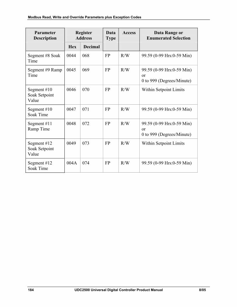
Modbus Read, Write and Override Parameters plus Exception Codes
184 UDC2500 Universal Digital Controller Product Manual 8/05
Parameter Description
Register Address
Data Type
Access Data Range or Enumerated Selection
Hex Decimal
Segment #8 Soak Time
0044 068 FP R/W 99.59 (0-99 Hrs:0-59 Min)
Segment #9 Ramp Time
0045 069 FP R/W 99.59 (0-99 Hrs:0-59 Min) or 0 to 999 (Degrees/Minute)
Segment #10 Soak Setpoint Value
0046 070 FP R/W Within Setpoint Limits
Segment #10 Soak Time
0047 071 FP R/W 99.59 (0-99 Hrs:0-59 Min)
Segment #11 Ramp Time
0048 072 FP R/W 99.59 (0-99 Hrs:0-59 Min) or 0 to 999 (Degrees/Minute)
Segment #12 Soak Setpoint Value
0049 073 FP R/W Within Setpoint Limits
Segment #12 Soak Time
004A 074 FP R/W 99.59 (0-99 Hrs:0-59 Min)
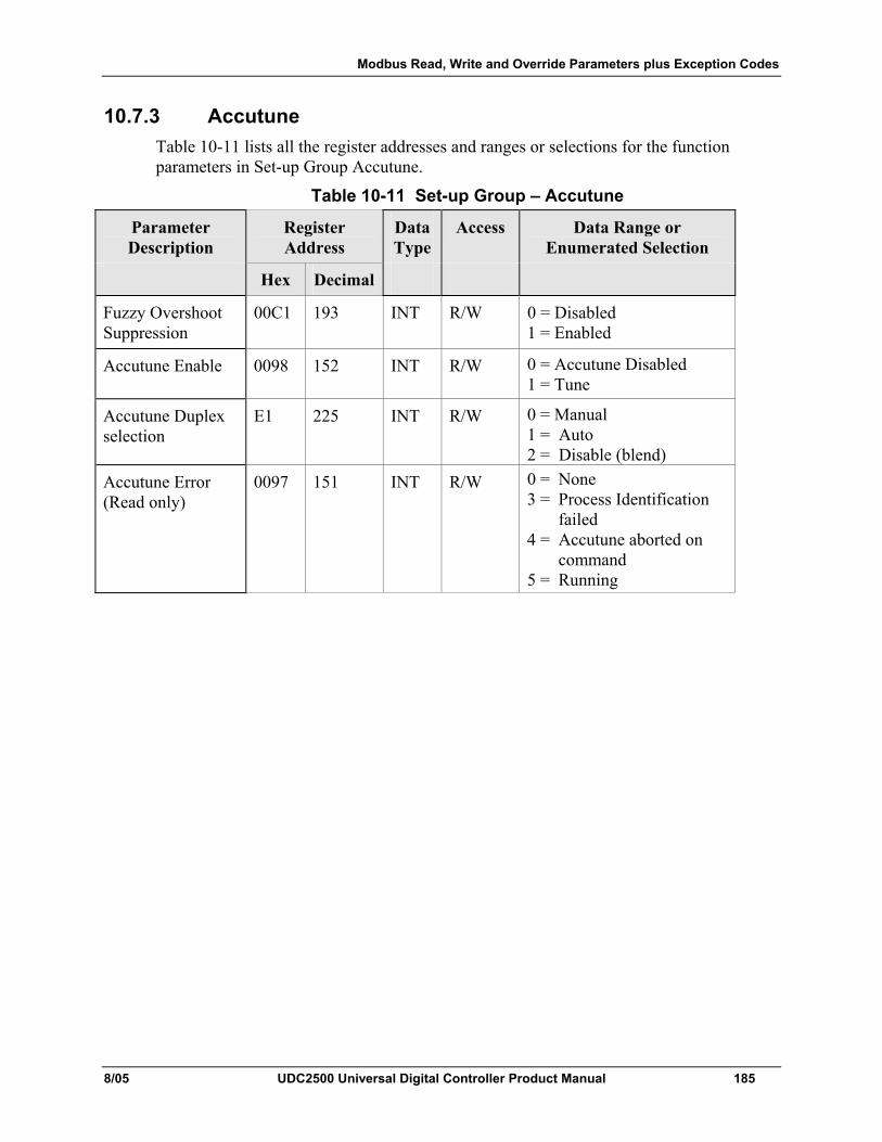
Modbus Read, Write and Override Parameters plus Exception Codes
8/05 UDC2500 Universal Digital Controller Product Manual 185
10.7.3 Accutune Table 10-11 lists all the register addresses and ranges or selections for the function parameters in Set-up Group Accutune.
Table 10-11 Set-up Group – Accutune
Parameter Description
Register Address
Data Type
Access Data Range or Enumerated Selection
Hex Decimal
Fuzzy Overshoot Suppression
00C1 193 INT R/W 0 = Disabled 1 = Enabled
Accutune Enable 0098 152 INT R/W 0 = Accutune Disabled 1 = Tune
Accutune Duplex selection
E1 225 INT R/W 0 = Manual 1 = Auto 2 = Disable (blend)
Accutune Error (Read only)
0097 151 INT R/W 0 = None 3 = Process Identification
failed 4 = Accutune aborted on
command 5 = Running
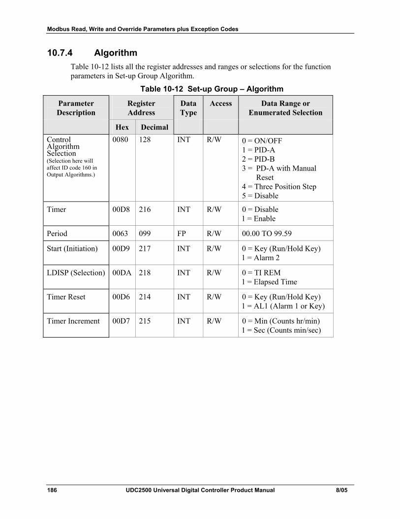
Modbus Read, Write and Override Parameters plus Exception Codes
186 UDC2500 Universal Digital Controller Product Manual 8/05
10.7.4 Algorithm Table 10-12 lists all the register addresses and ranges or selections for the function parameters in Set-up Group Algorithm.
Table 10-12 Set-up Group – Algorithm
Parameter Description
Register Address
Data Type
Access Data Range or Enumerated Selection
Hex Decimal Control Algorithm Selection (Selection here will affect ID code 160 in Output Algorithms.)
0080 128 INT R/W 0 = ON/OFF 1 = PID-A 2 = PID-B 3 = PD-A with Manual
Reset 4 = Three Position Step 5 = Disable
Timer 00D8 216 INT R/W 0 = Disable 1 = Enable
Period 0063 099 FP R/W 00.00 TO 99.59
Start (Initiation) 00D9 217 INT R/W 0 = Key (Run/Hold Key) 1 = Alarm 2
LDISP (Selection) 00DA 218 INT R/W 0 = TI REM 1 = Elapsed Time
Timer Reset 00D6 214 INT R/W 0 = Key (Run/Hold Key) 1 = AL1 (Alarm 1 or Key)
Timer Increment 00D7 215 INT R/W 0 = Min (Counts hr/min) 1 = Sec (Counts min/sec)
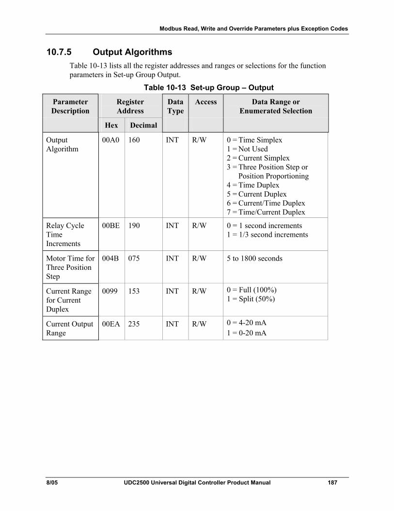
Modbus Read, Write and Override Parameters plus Exception Codes
8/05 UDC2500 Universal Digital Controller Product Manual 187
10.7.5 Output Algorithms Table 10-13 lists all the register addresses and ranges or selections for the function parameters in Set-up Group Output.
Table 10-13 Set-up Group – Output
Parameter Description
Register Address
Data Type
Access Data Range or Enumerated Selection
Hex Decimal
Output Algorithm
00A0 160 INT R/W 0 = Time Simplex 1 = Not Used 2 = Current Simplex 3 = Three Position Step or
Position Proportioning 4 = Time Duplex 5 = Current Duplex 6 = Current/Time Duplex 7 = Time/Current Duplex
Relay Cycle Time Increments
00BE 190 INT R/W 0 = 1 second increments 1 = 1/3 second increments
Motor Time for Three Position Step
004B 075 INT R/W 5 to 1800 seconds
Current Range for Current Duplex
0099 153 INT R/W 0 = Full (100%) 1 = Split (50%)
Current Output Range
00EA 235 INT R/W 0 = 4-20 mA 1 = 0-20 mA
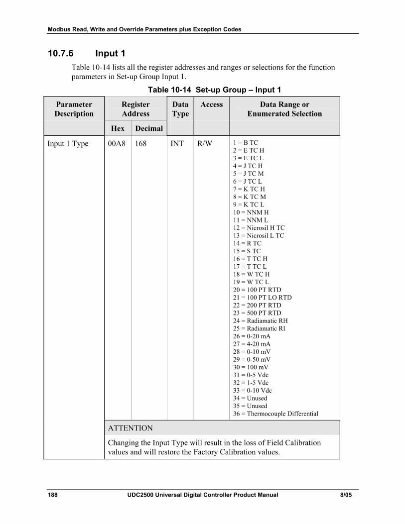
Modbus Read, Write and Override Parameters plus Exception Codes
188 UDC2500 Universal Digital Controller Product Manual 8/05
10.7.6 Input 1 Table 10-14 lists all the register addresses and ranges or selections for the function parameters in Set-up Group Input 1.
Table 10-14 Set-up Group – Input 1
Parameter Description
Register Address
Data Type
Access Data Range or Enumerated Selection
Hex Decimal
Input 1 Type 00A8 168 INT R/W 1 = B TC 2 = E TC H 3 = E TC L 4 = J TC H 5 = J TC M 6 = J TC L 7 = K TC H 8 = K TC M 9 = K TC L 10 = NNM H 11 = NNM L 12 = Nicrosil H TC 13 = Nicrosil L TC 14 = R TC 15 = S TC 16 = T TC H 17 = T TC L 18 = W TC H 19 = W TC L 20 = 100 PT RTD 21 = 100 PT LO RTD 22 = 200 PT RTD 23 = 500 PT RTD 24 = Radiamatic RH 25 = Radiamatic RI 26 = 0-20 mA 27 = 4-20 mA 28 = 0-10 mV 29 = 0-50 mV 30 = 100 mV 31 = 0-5 Vdc 32 = 1-5 Vdc 33 = 0-10 Vdc 34 = Unused 35 = Unused 36 = Thermocouple Differential
ATTENTION
Changing the Input Type will result in the loss of Field Calibration values and will restore the Factory Calibration values.
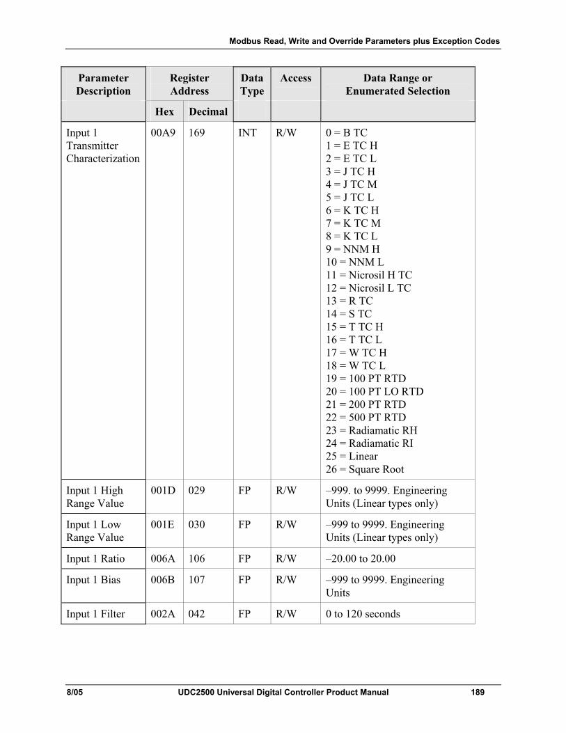
Modbus Read, Write and Override Parameters plus Exception Codes
8/05 UDC2500 Universal Digital Controller Product Manual 189
Parameter Description
Register Address
Data Type
Access Data Range or Enumerated Selection
Hex Decimal
Input 1 Transmitter Characterization
00A9 169 INT R/W 0 = B TC 1 = E TC H 2 = E TC L 3 = J TC H 4 = J TC M 5 = J TC L 6 = K TC H 7 = K TC M 8 = K TC L 9 = NNM H 10 = NNM L 11 = Nicrosil H TC 12 = Nicrosil L TC 13 = R TC 14 = S TC 15 = T TC H 16 = T TC L 17 = W TC H 18 = W TC L 19 = 100 PT RTD 20 = 100 PT LO RTD 21 = 200 PT RTD 22 = 500 PT RTD 23 = Radiamatic RH 24 = Radiamatic RI 25 = Linear 26 = Square Root
Input 1 High Range Value
001D 029 FP R/W –999. to 9999. Engineering Units (Linear types only)
Input 1 Low Range Value
001E 030 FP R/W –999 to 9999. Engineering Units (Linear types only)
Input 1 Ratio 006A 106 FP R/W –20.00 to 20.00
Input 1 Bias 006B 107 FP R/W –999 to 9999. Engineering Units
Input 1 Filter 002A 042 FP R/W 0 to 120 seconds
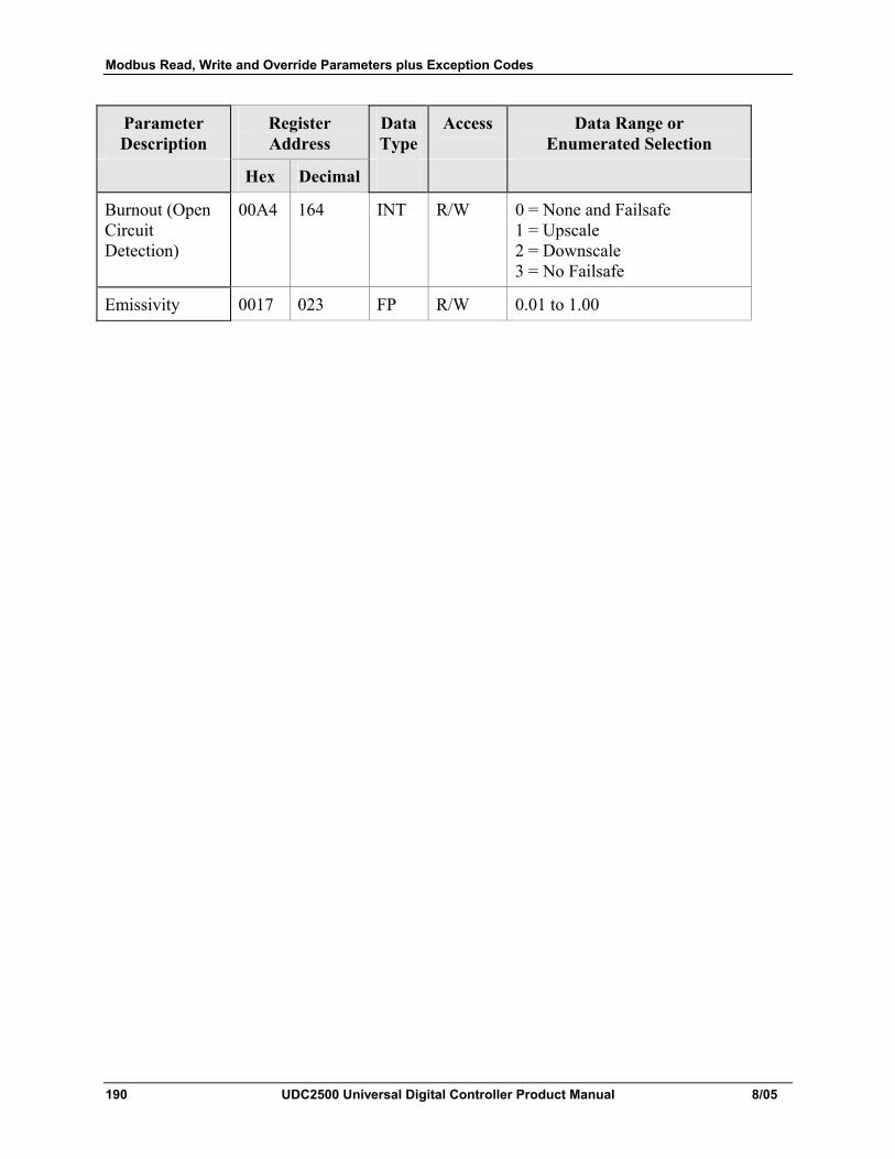
Modbus Read, Write and Override Parameters plus Exception Codes
190 UDC2500 Universal Digital Controller Product Manual 8/05
Parameter Description
Register Address
Data Type
Access Data Range or Enumerated Selection
Hex Decimal
Burnout (Open Circuit Detection)
00A4 164 INT R/W 0 = None and Failsafe 1 = Upscale 2 = Downscale 3 = No Failsafe
Emissivity 0017 023 FP R/W 0.01 to 1.00
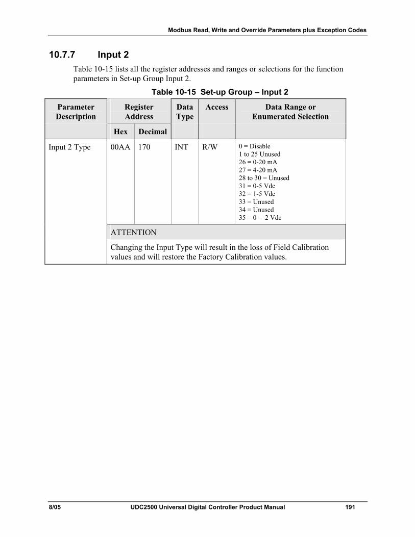
Modbus Read, Write and Override Parameters plus Exception Codes
8/05 UDC2500 Universal Digital Controller Product Manual 191
10.7.7 Input 2 Table 10-15 lists all the register addresses and ranges or selections for the function parameters in Set-up Group Input 2.
Table 10-15 Set-up Group – Input 2
Parameter Description
Register Address
Data Type
Access Data Range or Enumerated Selection
Hex Decimal
Input 2 Type 00AA 170 INT R/W 0 = Disable 1 to 25 Unused 26 = 0-20 mA 27 = 4-20 mA 28 to 30 = Unused 31 = 0-5 Vdc 32 = 1-5 Vdc 33 = Unused 34 = Unused 35 = 0 – 2 Vdc
ATTENTION
Changing the Input Type will result in the loss of Field Calibration values and will restore the Factory Calibration values.
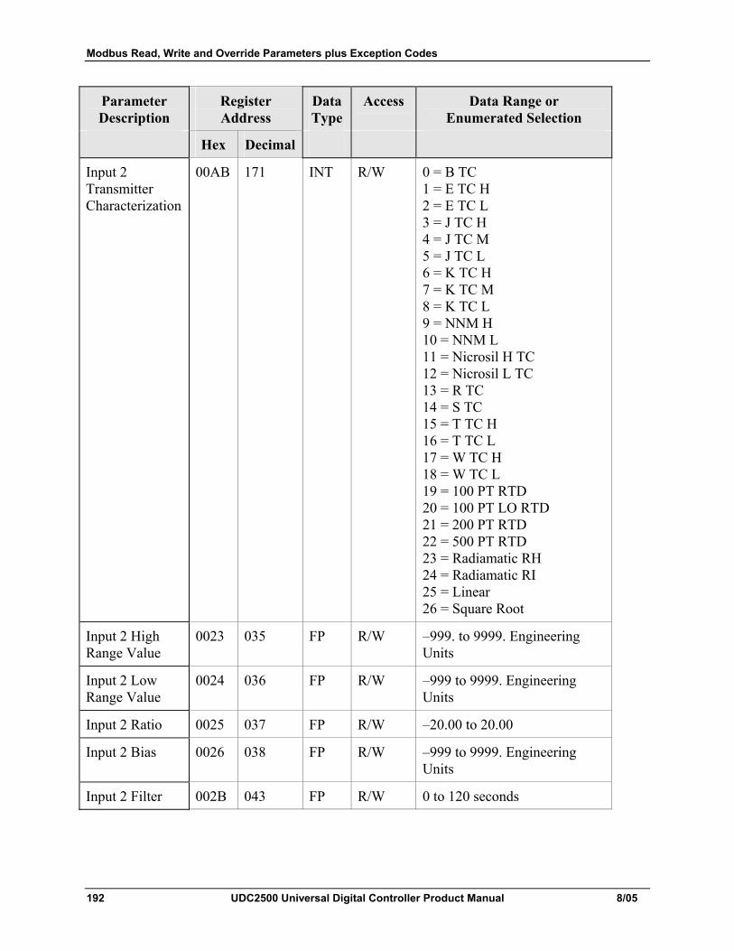
Modbus Read, Write and Override Parameters plus Exception Codes
192 UDC2500 Universal Digital Controller Product Manual 8/05
Parameter Description
Register Address
Data Type
Access Data Range or Enumerated Selection
Hex Decimal
Input 2 Transmitter Characterization
00AB 171 INT R/W 0 = B TC 1 = E TC H 2 = E TC L 3 = J TC H 4 = J TC M 5 = J TC L 6 = K TC H 7 = K TC M 8 = K TC L 9 = NNM H 10 = NNM L 11 = Nicrosil H TC 12 = Nicrosil L TC 13 = R TC 14 = S TC 15 = T TC H 16 = T TC L 17 = W TC H 18 = W TC L 19 = 100 PT RTD 20 = 100 PT LO RTD 21 = 200 PT RTD 22 = 500 PT RTD 23 = Radiamatic RH 24 = Radiamatic RI 25 = Linear 26 = Square Root
Input 2 High Range Value
0023 035 FP R/W –999. to 9999. Engineering Units
Input 2 Low Range Value
0024 036 FP R/W –999 to 9999. Engineering Units
Input 2 Ratio 0025 037 FP R/W –20.00 to 20.00
Input 2 Bias 0026 038 FP R/W –999 to 9999. Engineering Units
Input 2 Filter 002B 043 FP R/W 0 to 120 seconds
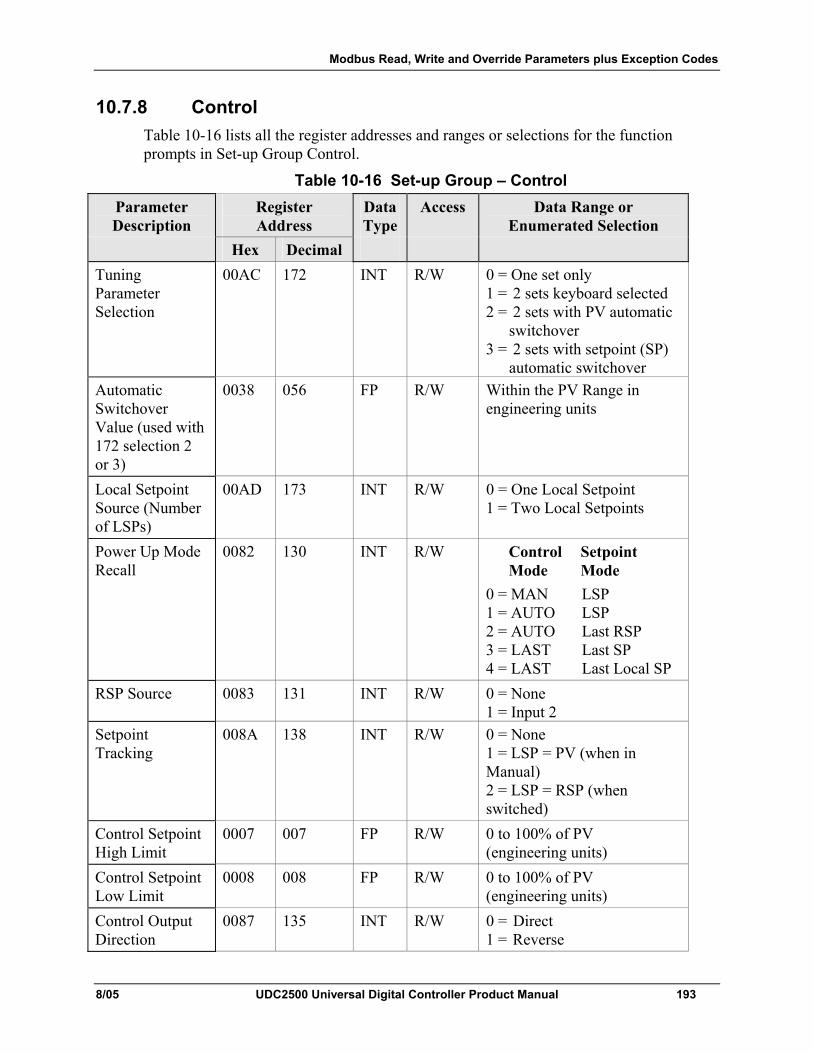
Modbus Read, Write and Override Parameters plus Exception Codes
8/05 UDC2500 Universal Digital Controller Product Manual 193
10.7.8 Control Table 10-16 lists all the register addresses and ranges or selections for the function prompts in Set-up Group Control.
Table 10-16 Set-up Group – Control Parameter Description
Register Address
Data Type
Access Data Range or Enumerated Selection
Hex Decimal Tuning Parameter Selection
00AC 172 INT R/W 0 = One set only 1 = 2 sets keyboard selected 2 = 2 sets with PV automatic
switchover 3 = 2 sets with setpoint (SP)
automatic switchover Automatic Switchover Value (used with 172 selection 2 or 3)
0038 056 FP R/W Within the PV Range in engineering units
Local Setpoint Source (Number of LSPs)
00AD 173 INT R/W 0 = One Local Setpoint 1 = Two Local Setpoints
Power Up Mode Recall
0082 130 INT R/W Control Setpoint Mode Mode 0 = MAN LSP 1 = AUTO LSP 2 = AUTO Last RSP 3 = LAST Last SP 4 = LAST Last Local SP
RSP Source 0083 131 INT R/W 0 = None 1 = Input 2
Setpoint Tracking
008A 138 INT R/W 0 = None 1 = LSP = PV (when in Manual) 2 = LSP = RSP (when switched)
Control Setpoint High Limit
0007 007 FP R/W 0 to 100% of PV (engineering units)
Control Setpoint Low Limit
0008 008 FP R/W 0 to 100% of PV (engineering units)
Control Output Direction
0087 135 INT R/W 0 = Direct 1 = Reverse
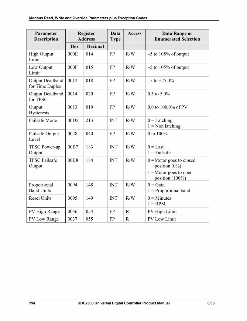
Modbus Read, Write and Override Parameters plus Exception Codes
194 UDC2500 Universal Digital Controller Product Manual 8/05
Parameter Description
Register Address
Data Type
Access Data Range or Enumerated Selection
Hex Decimal High Output Limit
000E 014 FP R/W –5 to 105% of output
Low Output Limit
000F 015 FP R/W –5 to 105% of output
Output Deadband for Time Duplex
0012 018 FP R/W –5 to +25.0%
Output Deadband for TPSC
0014 020 FP R/W 0.5 to 5.0%
Output Hysteresis
0013 019 FP R/W 0.0 to 100.0% of PV
Failsafe Mode 00D5 213 INT R/W 0 = Latching 1 = Non latching
Failsafe Output Level
0028 040 FP R/W 0 to 100%
TPSC Power-up Output
00B7 183 INT R/W 0 = Last 1 = Failsafe
TPSC Failsafe Output
00B8 184 INT R/W 0 = Motor goes to closed position (0%)
1 = Motor goes to open position (100%)
Proportional Band Units
0094 148 INT R/W 0 = Gain 1 = Proportional band
Reset Units 0095 149 INT R/W 0 = Minutes 1 = RPM
PV High Range 0036 054 FP R PV High Limit PV Low Range 0037 055 FP R PV Low Limit
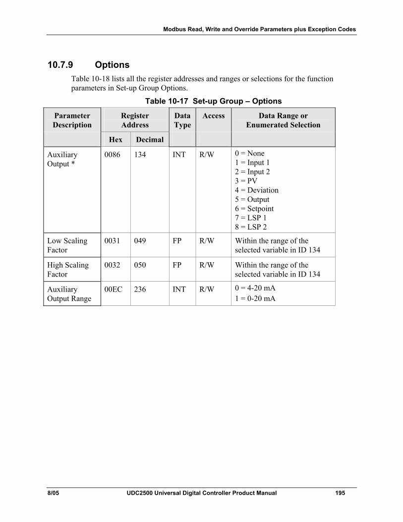
Modbus Read, Write and Override Parameters plus Exception Codes
8/05 UDC2500 Universal Digital Controller Product Manual 195
10.7.9 Options Table 10-18 lists all the register addresses and ranges or selections for the function parameters in Set-up Group Options.
Table 10-17 Set-up Group – Options
Parameter Description
Register Address
Data Type
Access Data Range or Enumerated Selection
Hex Decimal
Auxiliary Output *
0086 134 INT R/W 0 = None 1 = Input 1 2 = Input 2 3 = PV 4 = Deviation 5 = Output 6 = Setpoint 7 = LSP 1 8 = LSP 2
Low Scaling Factor
0031 049 FP R/W Within the range of the selected variable in ID 134
High Scaling Factor
0032 050 FP R/W Within the range of the selected variable in ID 134
Auxiliary Output Range
00EC 236 INT R/W 0 = 4-20 mA 1 = 0-20 mA
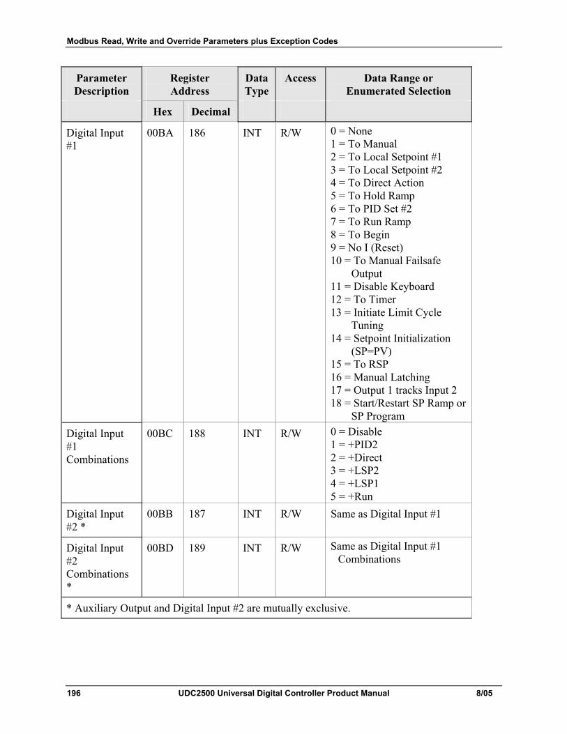
Modbus Read, Write and Override Parameters plus Exception Codes
196 UDC2500 Universal Digital Controller Product Manual 8/05
Parameter Description
Register Address
Data Type
Access Data Range or Enumerated Selection
Hex Decimal
Digital Input #1
00BA 186 INT R/W 0 = None 1 = To Manual 2 = To Local Setpoint #1 3 = To Local Setpoint #2 4 = To Direct Action 5 = To Hold Ramp 6 = To PID Set #2 7 = To Run Ramp 8 = To Begin 9 = No I (Reset) 10 = To Manual Failsafe
Output 11 = Disable Keyboard 12 = To Timer 13 = Initiate Limit Cycle
Tuning 14 = Setpoint Initialization
(SP=PV) 15 = To RSP 16 = Manual Latching 17 = Output 1 tracks Input 2 18 = Start/Restart SP Ramp or
SP Program Digital Input #1 Combinations
00BC 188 INT R/W 0 = Disable 1 = +PID2 2 = +Direct 3 = +LSP2 4 = +LSP1 5 = +Run
Digital Input #2 *
00BB 187 INT R/W Same as Digital Input #1
Digital Input #2 Combinations *
00BD 189 INT R/W Same as Digital Input #1 Combinations
* Auxiliary Output and Digital Input #2 are mutually exclusive.
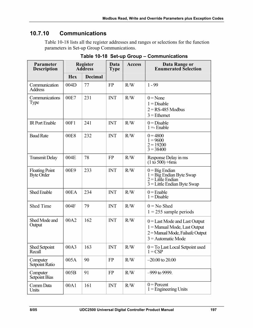
Modbus Read, Write and Override Parameters plus Exception Codes
8/05 UDC2500 Universal Digital Controller Product Manual 197
10.7.10 Communications Table 10-18 lists all the register addresses and ranges or selections for the function parameters in Set-up Group Communications.
Table 10-18 Set-up Group – Communications Parameter Description
Register Address
Data Type
Access Data Range or Enumerated Selection
Hex Decimal
CommunicationAddress
004D 77 FP R/W 1 - 99
Communications Type
00E7 231 INT R/W 0 = None 1 = Disable 2 = RS-485 Modbus 3 = Ethernet
IR Port Enable 00F1 241 INT R/W 0 = Disable 1 =- Enable
Baud Rate 00E8 232 INT R/W 0 = 4800 1 = 9600 2 = 19200 3 = 38400
Transmit Delay 004E 78 FP R/W Response Delay in ms (1 to 500) +6ms
Floating Point Byte Order
00E9 233 INT R/W 0 = Big Endian 1 = Big Endian Byte Swap 2 = Little Endian 3 = Little Endian Byte Swap
Shed Enable 00EA 234 INT R/W 0 = Enable 1 = Disable
Shed Time 004F 79 INT R/W 0 = No Shed 1 = 255 sample periods
Shed Mode and Output
00A2 162 INT R/W 0 = Last Mode and Last Output 1 = Manual Mode, Last Output 2 = Manual Mode, Failsafe Output 3 = Automatic Mode
Shed Setpoint Recall
00A3 163 INT R/W 0 = To Last Local Setpoint used 1 = CSP
Computer Setpoint Ratio
005A 90 FP R/W –20.00 to 20.00
Computer Setpoint Bias
005B 91 FP R/W –999 to 9999.
Comm Data Units
00A1 161 INT R/W 0 = Percent 1 = Engineering Units
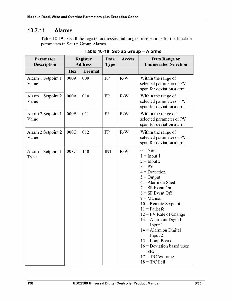
Modbus Read, Write and Override Parameters plus Exception Codes
198 UDC2500 Universal Digital Controller Product Manual 8/05
10.7.11 Alarms Table 10-19 lists all the register addresses and ranges or selections for the function parameters in Set-up Group Alarms.
Table 10-19 Set-up Group – Alarms Parameter Description
Register Address
Data Type
Access Data Range or Enumerated Selection
Hex Decimal Alarm 1 Setpoint 1 Value
0009 009 FP R/W Within the range of selected parameter or PV span for deviation alarm
Alarm 1 Setpoint 2 Value
000A 010 FP R/W Within the range of selected parameter or PV span for deviation alarm
Alarm 2 Setpoint 1 Value
000B 011 FP R/W Within the range of selected parameter or PV span for deviation alarm
Alarm 2 Setpoint 2 Value
000C 012 FP R/W Within the range of selected parameter or PV span for deviation alarm
Alarm 1 Setpoint 1 Type
008C 140 INT R/W 0 = None 1 = Input 1 2 = Input 2 3 = PV 4 = Deviation 5 = Output 6 = Alarm on Shed 7 = SP Event On 8 = SP Event Off 9 = Manual 10 = Remote Setpoint 11 = Failsafe 12 = PV Rate of Change 13 = Alarm on Digital
Input 1 14 = Alarm on Digital
Input 2 15 = Loop Break 16 = Deviation based upon
SP2 17 = T/C Warning 18 = T/C Fail
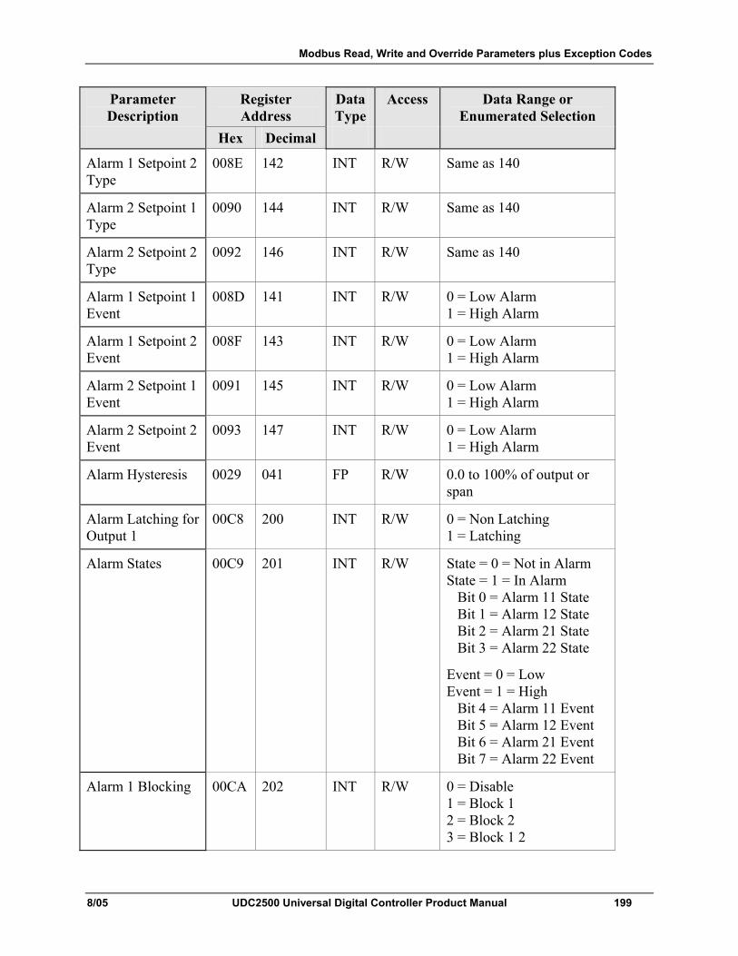
Modbus Read, Write and Override Parameters plus Exception Codes
8/05 UDC2500 Universal Digital Controller Product Manual 199
Parameter Description
Register Address
Data Type
Access Data Range or Enumerated Selection
Hex Decimal
Alarm 1 Setpoint 2 Type
008E 142 INT R/W Same as 140
Alarm 2 Setpoint 1 Type
0090 144 INT R/W Same as 140
Alarm 2 Setpoint 2 Type
0092 146 INT R/W Same as 140
Alarm 1 Setpoint 1 Event
008D 141 INT R/W 0 = Low Alarm 1 = High Alarm
Alarm 1 Setpoint 2 Event
008F 143 INT R/W 0 = Low Alarm 1 = High Alarm
Alarm 2 Setpoint 1 Event
0091 145 INT R/W 0 = Low Alarm 1 = High Alarm
Alarm 2 Setpoint 2 Event
0093 147 INT R/W 0 = Low Alarm 1 = High Alarm
Alarm Hysteresis 0029 041 FP R/W 0.0 to 100% of output or span
Alarm Latching for Output 1
00C8 200 INT R/W 0 = Non Latching 1 = Latching
Alarm States 00C9 201 INT R/W State = 0 = Not in Alarm State = 1 = In Alarm Bit 0 = Alarm 11 State Bit 1 = Alarm 12 State Bit 2 = Alarm 21 State Bit 3 = Alarm 22 State
Event = 0 = Low Event = 1 = High Bit 4 = Alarm 11 Event Bit 5 = Alarm 12 Event Bit 6 = Alarm 21 Event Bit 7 = Alarm 22 Event
Alarm 1 Blocking 00CA 202 INT R/W 0 = Disable 1 = Block 1 2 = Block 2 3 = Block 1 2
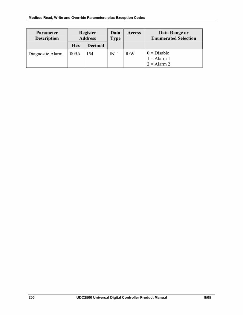
Modbus Read, Write and Override Parameters plus Exception Codes
200 UDC2500 Universal Digital Controller Product Manual 8/05
Parameter Description
Register Address
Data Type
Access Data Range or Enumerated Selection
Hex Decimal
Diagnostic Alarm 009A 154 INT R/W 0 = Disable 1 = Alarm 1 2 = Alarm 2
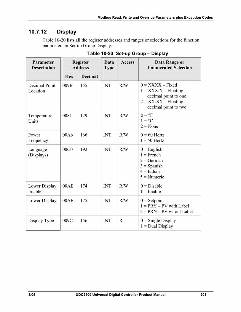
Modbus Read, Write and Override Parameters plus Exception Codes
8/05 UDC2500 Universal Digital Controller Product Manual 201
10.7.12 Display Table 10-20 lists all the register addresses and ranges or selections for the function parameters in Set-up Group Display.
Table 10-20 Set-up Group – Display
Parameter Description
Register Address
Data Type
Access Data Range or Enumerated Selection
Hex Decimal
Decimal Point Location
009B 155 INT R/W 0 = XXXX – Fixed 1 = XXX.X – Floating
decimal point to one 2 = XX.XX – Floating
decimal point to two
Temperature Units
0081 129 INT R/W 0 = °F 1 = °C 2 = None
Power Frequency
00A6 166 INT R/W 0 = 60 Hertz 1 = 50 Hertz
Language (Displays)
00C0 192 INT R/W 0 = English 1 = French 2 = German 3 = Spanish 4 = Italian 5 = Numeric
Lower Display Enable
00AE 174 INT R/W 0 = Disable 1 = Enable
Lower Display 00AF 175 INT R/W 0 = Setpoint 1 = PRY – PV with Label 2 = PRN – PV witout Label
Display Type 009C 156 INT R 0 = Single Display 1 = Dual Display
Modbus Read, Write and Override Parameters plus Exception Codes
202 UDC2500 Universal Digital Controller Product Manual 8/05
10.8 Modbus RTU Exception Codes
Introduction When a master device sends a query to a slave device it expects a normal response. One of four possible events can occur from the master’s query:
• Slave device receives the query without a communication error and can handle the query normally. It returns a normal response.
• Slave does not receive the query due to a communication error. No response is returned. The master program will eventually process a time-out condition for the query.
• Slave receives the query but detects a communication error (parity, LRC or CRC). No response is returned. The master program will eventually process a time-out condition for the query.
• Slave receives the query without a communication error but cannot handle it (i.e., request is to a non-existent coil or register). The slave will return with an exception response informing the master of the nature of the error (Illegal Data Address.)
The exception response message has two fields that differentiate it from a normal response:
Function Code Field: In a normal response, the slave echoes the function code of the original query in the function code field of the response. All function codes have a most-significant bit (MSB) of 0 (their values are below 80 hex). In an exception response, the slave sets the MSB of the function code to 1. This makes the function code value in an exception response exactly 80 hex higher than the value would be for a normal response.
With the function code’s MSB set, the master’s application program can recognize the exception response and can examine the data field for the exception code.
Data Field: In a normal response, the slave may return data or statistics in the data field. In an exception response, the slave returns an exception code in the data field. This defines the slave condition that caused the exception.
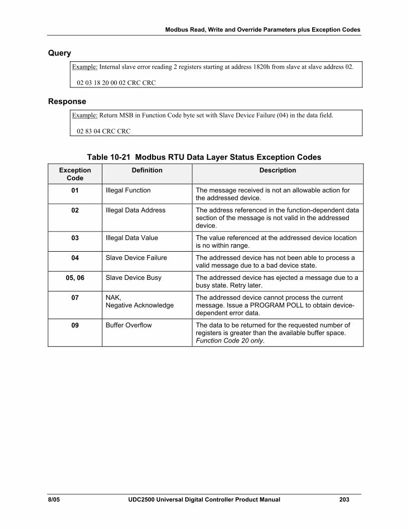
Modbus Read, Write and Override Parameters plus Exception Codes
8/05 UDC2500 Universal Digital Controller Product Manual 203
Query Example: Internal slave error reading 2 registers starting at address 1820h from slave at slave address 02. 02 03 18 20 00 02 CRC CRC
Response Example: Return MSB in Function Code byte set with Slave Device Failure (04) in the data field. 02 83 04 CRC CRC
Table 10-21 Modbus RTU Data Layer Status Exception Codes Exception
Code Definition Description
01 Illegal Function The message received is not an allowable action for the addressed device.
02 Illegal Data Address The address referenced in the function-dependent data section of the message is not valid in the addressed device.
03 Illegal Data Value The value referenced at the addressed device location is no within range.
04 Slave Device Failure The addressed device has not been able to process a valid message due to a bad device state.
05, 06 Slave Device Busy The addressed device has ejected a message due to a busy state. Retry later.
07 NAK, Negative Acknowledge
The addressed device cannot process the current message. Issue a PROGRAM POLL to obtain device-dependent error data.
09 Buffer Overflow The data to be returned for the requested number of registers is greater than the available buffer space. Function Code 20 only.
Ethernet TCP/IP
204 UDC2500 Universal Digital Controller Product Manual 8/05
11 Ethernet TCP/IP
11.1 Overview Ethernet parameters can only be configured via the Process Instrument Explorer software.
Ethernet IP Address is 10.0.0.2 as shipped from the Factory.
The MAC address is printed on the case label of each instrument.
When constructing a network, it is recommended that a Switch be used to connect UDCs to a LAN rather than using a Hub. This is because a Switch passes only those messages for IP addresses that are connected to the Switch while a Hub passes all message traffic. Using a Switch thus improves the overall throughput of the traffic to and from the UDCs.
Further information
8/05 UDC2500 Universal Digital Controller Product Manual 205
12 Further information
12.1 Modbus RTU Serial Communications Refer to document 51-52-25-66 Modbus RTU Serial Communications User Manual.
12.2 Modbus Messaging on TCP/IP Refer to document 51-52-25-121 MODBUS Messaging on TCP/IP Implementation Guide.
12.3 How to Apply Digital Instrumentation in Severe Electrical Noise Environments
Refer to document 51-52-05-01 How to Apply Digital Instrumentation in Severe Electrical Noise Environments.

206 UDC2500 Universal Digital Controller Product Manual 8/05
8/05 UDC2500 Universal Digital Controller Product Manual 207
13 Index
A Aborting Accutune, 114 Accutune Error Codes, 114 Accutune Error Status, 49 Accutune III, 109 Accutune Set Up Group, 47, 89 Adaptive tune, 48 Alarm blocking, 88 Alarm Hysteresis, 87 Alarm Outputs, 9 Alarm Relay Output failure, 164 Alarm Relays, 14 Alarm Setpoints, 117 Alarm Setpoints Display, 117 Alarms Set Up Group, 83 Algorithm Set Up Group, 50 Analog Inputs, 8 Annunciators, 97 Application related problems, 153 ATUNE Group, 48, 89 Auto/Manual key, 96 Automatic with local setpoint, 104 Automatic with remote setpoint, 104 Auto-only Mode, 101 Autotune is complete, 115 Auxiliary Output Calibration, 148 Auxiliary Output Calibration Procedure, 149 Auxiliary Output Connections, 32 Auxiliary Output Failure, 167 B Background Tests, 156 Baud Rate, 79 Bias, 61, 65 Blended Tune, 112 Burnout protection, 61 C Calibration Mode, 143, 150 Calibration Steps, 131 CE Conformity (Europe), 5 Changing Control Modes, 105 Changing the Local Setpoints, 105 Communications failure, 166, 167 Communications Interface, 10 Composite Wiring Diagram, 21 Computer Setpoint, 187 Computer setpoint ratio, 81 Configuration, 34 Configuration Parameters, 189 Configuration Procedure, 37 Configuration Prompt Hierarchy, 35
Control algorithm, 50 Control and Alarm Relay Contact Information, 14 Control Modes, 104 Control Relays, 14 Control Set Up Group, 66, 73, 79 Control/Alarm Circuit Wiring, 17 Controller Failure Symptoms, 158 Controller Grounding, 17 Controller Output Types, 9 Current duplex, 56 Current Output, 28 Current Output Calibration, 146 Current Output Calibration Procedure, 147 Current Output Failure, 160 Current simplex, 56 Current/time duplex, 56 Current/Time or Time/Current Proportional Output
failure, 163 Cycle time (cool), 40 Cycle time (heat), 40 D Deadband, 70 Decimal Places, 89 Demand Tuning, 47 Diagnostic Alarm, 88 Diagnostic Message, 99 Digital input (remote) operation, 129 Digital input selections, 75 Digital Inputs, 8 Digital Inputs Option Connections, 32 Dimensions, 15 Direct acting control, 69 Displays, 3 Dual Electromechanical Relay Option Output, 28 Duplex Control, 111, 113 E Elapsed Time, 108 Electrical Considerations, 17 Electrical Noise Precautions, 18 Electromechanical Relay Output, 25 Emissivity, 62 End segment number, 124 Environmental and Operating Conditions, 10 Equipment You Will Need To Calibrate, 133 Error Codes, 114 Error Messages, 99 Estimated Motor Position, 118 Ethernet TCP/IP, 213 Ethernet Tcp/Ip Communications Interface, 10 External Interface Option Connections, 30, 32
208 UDC2500 Universal Digital Controller Product Manual 8/05
External setpoint program reset, 76 External Wiring, 18 F Factory calibration, 143, 150 Failsafe Function Prompt, 119, 120 Failsafe Manual Mode, 155 Failsafe mode, 72 Failsafe Mode, 120 Failsafe output value, 70 Failsafe Output Value, 119 Failsafe Output Value for Restart After a Power
Loss, 119 Field Wiring, 133 Filter, 61, 65 Floating Point Parameter Type, 173 Function code 20, 174 Function Code 21, 178 function codes 20 and 21, 172 Function Prompts, 35 Fuzzy Overshoot Suppression, 47, 115 Fuzzy Overshoot Suppression, 48 G Gain, 38 Gain 2, 39 Guaranteed soak, 124 H Hotstart, 77 Hysteresis (output relay), 70 I,J Infrared communications, 5 Infrared Communications, 10 Infrared Communications, 79 Input 1 actuation type, 59, 63 Input 1 and Input 2 Wiring Terminals, 133 Input 1 Calibration Procedure, 138 Input 1 Connections, 23 Input 1 high range value, 60, 64 Input 1 low range value, 61, 65 Input 1 Set Up Group, 59 Input 1 Set Up Wiring, 134 Input 2 Calibration Procedure, 141 Input 2 Connections, 24 Input 2 Set Up Group, 63 Input 2 Set Up Wiring, 140, 141 Input Calibration, 130 Installation, 7 Installation related problems, 153 Integer Parameter Type, 173 Isolation, 9 K Key error, 96 key lockout, 96 Keyboard failure, 165 Keys, 3
L Latching, 120 Local setpoint source, 67 Lockout, 41 Lockout Feature, 95 Lockout levels, 95 Loopback Test, 82 Lower Display Key Parameter Prompts, 98 M Mains Power Supply, 17, 22 Manual, 104 Manual reset, 39 Manual Tune, 112 Manual/Auto key lockout, 41 Minimum and Maximum Range Values, 131 Modbus Read, Write and Override Parameters, 181 Modbus RTU Exception Codes, 211 Modbus RTU Function Codes, 172 Model Number Interpretation, 12 Monitoring t, 93 Motor Position Display, 118 Motor Time, 58 Mounting, 15 Mounting Method, 16 Mounting Procedure, 16 N Non-Latching, 120 O Open Collector Output, 27 Operating Parameters, 98 Operator Interface, 94 Option Status, 183 Output Algorithm, 55 Output Calibration, 145 Output Limit, 70 Output Set Up Group, 55 Overriding Controller Setpoint, 187 P,Q Parts Identification, 170 Parts List, 169 PD with manual reset, 52 Permissible Wiring Bundling, 18 Physical Considerations, 15 PID A, 51 PID B, 51 Position proportional or 3 position step test failures,
155 Power Consumption, 10 Power Failure Symptoms, 160 Power Inrush Current, 10 Power Line Frequency, 90 Power outage, 129 Power Outage, 122 Power-up Tests, 155
8/05 UDC2500 Universal Digital Controller Product Manual 209
Pre-installation Information, 8 Process Instrument Explorer, 4 Program Contents, 123 Program record sheet, 127 Program state, 125 Program termination state, 125 Proportional band, 38 Proportional band 2, 39 Proportional band units, 72 PV Hot Start, 120 R Ramp time or rate segments, 123 Ramp unit, 124 Ramp/soak profile example, 125 Rate, 38 Rate 2, 39 Ratio, 61, 65 Read Onlys, 184 Reading Control Data, 182 Recycle number, 124 Register Address Structure, 173 Register Count, 173 Relay Cycle Times, 58 Remote setpoint source, 68 Removing the chassis, 171 Reset, 39 Reset 2, 39 Reset Program to Beginning, 125 Reset units, 72 Restore Factory Calibration, 143 Restore Output Factory Calibration, 150 Restoring Factory Configuration, 168 Reverse acting control, 70 RTD Inputs, 135 Run/Hold key, 96 RUN/HOLD key, 121 Run/Hold key lockout, 41 Run/Monitor the program, 128 S Security code, 40 Security Code, 94 Set Point Select function key, 96 Set Up Group, 35 Set Up Wiring Procedure for Auxiliary Output, 148 Setpoint Code Selections, 185 Setpoint high limit, 69 Setpoint low limit, 69 Setpoint ramp, 43 Setpoint Ramp, 121 Setpoint ramp final setpoint, 44 Setpoint ramp time, 43 Setpoint Ramp/Soak Programming, 123 Setpoint rate, 44 Setpoint Rate, 122
Setpoint Select key lockout, 41 Setpoint tracking, 68 Setpoints, 105, 185 Set-up Group Accutune, 194 Set-up Group Alarms, 207 Set-up Group Algorithm, 195 Set-up Group Communications, 206 Set-up Group Control, 202 Set-up Group Display, 210 Set-up Group Input 1, 197 Set-up Group Input 2, 200 Set-up Group Options, 204 Set-up Group Output, 196 Set-up Group Setpoint Ramp/Rate, 191 Set-up Group Tuning, 189 Shed Time, 80 Single Display Functionality, 101 Single Display Parameters, 102 Soak segments, 124 Software Options Status, 183 Software Type, 184, 185 Software Version, 184, 185 Software Version Number, 154 Solid State Relay Output, 26 SP Ramp Set Up Group, 43 SP Tuning, 47 Specifications, 8 SPPROG, 45 SPRATE, 44 Start segment number, 124 Start Up Procedure for Operation, 103 Station Address, 79 Status Tests, 155 Stray Rejection, 8 Suppression Devices, 18 Switch between two sets via keyboard, 117 Switching between setpoints, 107 T Temperature Units, 89 Test Failures, 155 Thermocouple Inputs Using a Thermocouple Source,
135 Thermocouple Inputs Using an Ice Bath, 134 Three Position Step, 52 Three Position Step Control algorithm, 118 Three Position Step Control Connections, 29 Three Position Step Control Output Failure, 161 Time Current Duplex, 56 Time duplex, 56 Time proportional output, 55 Time Proportional Output failure, 162 Time Remaining, 108 Time simplex, 55 Time-Out, 108 Timer, 107
210 UDC2500 Universal Digital Controller Product Manual 8/05
Timer, 53 Transmitter characterization, 60 Transmitter Power for 4-20 mA, 32, 33 Troubleshooting Aids, 153 Troubleshooting Procedures, 159 Troubleshooting/Service, 152 Tune, 48, 109 Tune for Duplex (Heat/Cool), 110 Tuning, 38 Tuning indicators, 109 Tuning parameter sets, 66 Tuning Set Up Group, 38 Two Sets of Tuning Constants, 115 TX DELAY, 80 U Universal Output Functionality and Restrictions, 20
V Voltage and Resistance Equivalents for 0% and
100% Range Values, 131, 133 W,X,Y,Z Weigh, 10 Wiring, 17 Wiring Bundling, 18 Wiring Connections for 1 to 5 Volt Input – Input 2,
141 Wiring Connections for 4 to 20 mA Input – Input 2,
140 Wiring Connections for Calibrating Auxiliary
Output, 148 Wiring Connections for Calibrating Current Output,
146 Wiring Connections for Radiamatic, Milliampere,
Millivolts, or Volts (Except 0 to 10 Volts), 136, 137
Wiring Connections for RTD (Resistance Thermometer Device), 135
Wiring Diagrams, 19 Wiring the Controller, 21 Worksheet, 123

