honeywell hts-900-2-1d engine installation bell 407 …eaglecopters-documents.com/fms-e407-789-1 rev...
TRANSCRIPT
• COPYRIGHT © 2013 BY EAGLE COPTERS LTD • This document is private and confidential and is supplied on the express condition that it is not to be used for any
purpose or copied or communicated to any other person without written permission from Eagle Copters Ltd.
Revision: 2 Unapproved Date: 23 JAN 2018
Eagle Copters Ltd. 823 McTavish Road NE Calgary, Alberta, Canada T2E 7G9 Tel: 1 403 250 7370 Fax: 1 403 250 7110 http://www.eaglecopters.com
ROTORCRAFT FLIGHT MANUAL SUPPLEMENT FMS-E407-789-1
Honeywell HTS-900-2-1D Engine Installation
Bell 407 Models

FMS-E407-789-1 Page Intro-1
• COPYRIGHT © 2014 BY EAGLE COPTERS LTD • This document is private and confidential and is supplied on the express condition that it is not to be used for any
purpose or copied or communicated to any other person without written permission from Eagle Copters Ltd.
Revision: 2 TCCA Approved Date: 23 JAN 2018
Eagle Copters Ltd. 823 McTavish Road NE Calgary, Alberta, Canada T2E 7G9 Tel: 1 403 250 7370 Fax: 1 403 250 7110 http://www.eaglecopters.com
ROTORCRAFT FLIGHT MANUAL SUPPLEMENT FMS-E407-789-1
Honeywell HTS900-2-1D Engine Installation
Bell 407 Models SH14-47
Sections 1 – 4 of this document comprise the Approved Flight Manual Supplement. Compliance with Section1, Limitations is mandatory. Section 5 is unapproved and is provided for information only.
Prepared By: H. Siemens
Dart Aerospace
Reviewed By: D. Shepherd
Chief Engineer Dart Aerospace

FMS-E407-789-1 Page Intro-2
• COPYRIGHT © 2014 BY EAGLE COPTERS LTD • This document is private and confidential and is supplied on the express condition that it is not to be used for any
purpose or copied or communicated to any other person without written permission from Eagle Copters Ltd.
Revision: 2 TCCA Approved Date: 23 JAN 2018
This page intentionally left blank
FMS-E407-789-1 Page Intro-3
• COPYRIGHT © 2014 BY EAGLE COPTERS LTD • This document is private and confidential and is supplied on the express condition that it is not to be used for any
purpose or copied or communicated to any other person without written permission from Eagle Copters Ltd.
Revision: 2 TCCA Approved Date: 23 JAN 2018
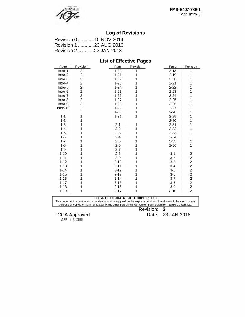
Log of Revisions Revision 0 ............ 10 NOV 2014 Revision 1 ............ 23 AUG 2016 Revision 2 ……….23 JAN 2018
List of Effective Pages Page Revision
Intro-1 2 Intro-2 2 Intro-3 2 Intro-4 2 Intro-5 2 Intro-6 2 Intro-7 2 Intro-8 2 Intro-9 2
Intro-10 2
1-1 1 1-2 1 1-3 1 1-4 1 1-5 1 1-6 1 1-7 1 1-8 1 1-9 1 1-10 1 1-11 1 1-12 1 1-13 1 1-14 1 1-15 1 1-16 1 1-17 1 1-18 1 1-19 1
Page Revision 1-20 1 1-21 1 1-22 1 1-23 1 1-24 1 1-25 1 1-26 1 1-27 1 1-28 1 1-29 1 1-30 1 1-31 1
2-1 1 2-2 1 2-3 1 2-4 1 2-5 1 2-6 1 2-7 1 2-8 1 2-9 1 2-10 1 2-11 1 2-12 1 2-13 1 2-14 1 2-15 1 2-16 1 2-17 1
Page Revision 2-18 1 2-19 1 2-20 1 2-21 1 2-22 1 2-23 1 2-24 1 2-25 1 2-26 1 2-27 1 2-28 1 2-29 1 2-30 1 2-31 1 2-32 1 2-33 1 2-34 1 2-35 1 2-36 1
3-1 2 3-2 2 3-3 2 3-4 2 3-5 2 3-6 2 3-7 2 3-8 2 3-9 2 3-10 2
FMS-E407-789-1 Page Intro-4
• COPYRIGHT © 2014 BY EAGLE COPTERS LTD • This document is private and confidential and is supplied on the express condition that it is not to be used for any
purpose or copied or communicated to any other person without written permission from Eagle Copters Ltd.
Revision: 2 TCCA Approved Date: 23 JAN 2018
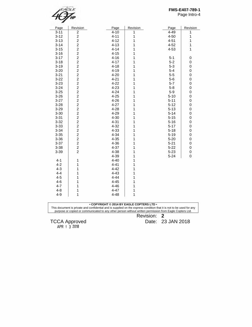
Page Revision 3-11 2 3-12 2 3-13 2 3-14 2 3-15 2 3-16 2 3-17 2 3-18 2 3-19 2 3-20 2 3-21 2 3-22 2 3-23 2 3-24 2 3-25 2 3-26 2 3-27 2 3-28 2 3-29 2 3-30 2 3-31 2 3-32 2 3-33 2 3-34 2 3-35 2 3-36 2 3-37 2 3-38 2 3-39 2
4-1 1 4-2 1 4-3 1 4-4 1 4-5 1 4-6 1 4-7 1 4-8 1 4-9 1
Page Revision 4-10 1 4-11 1 4-12 1 4-13 1 4-14 1 4-15 1 4-16 1 4-17 1 4-18 1 4-19 1 4-20 1 4-21 1 4-22 1 4-23 1 4-24 1 4-25 1 4-26 1 4-27 1 4-28 1 4-29 1 4-30 1 4-31 1 4-32 1 4-33 1 4-34 1 4-35 1 4-36 1 4-37 1 4-38 1 4-39 1 4-40 1 4-41 1 4-42 1 4-43 1 4-44 1 4-45 1 4-46 1 4-47 1 4-48 1
Page Revision 4-49 1 4-50 1 4-51 1 4-52 1 4-53 1
5-1 0 5-2 0 5-3 0 5-4 0 5-5 0 5-6 0 5-7 0 5-8 0 5-9 0 5-10 0 5-11 0 5-12 0 5-13 0 5-14 0 5-15 0 5-16 0 5-17 0 5-18 0 5-19 0 5-20 0 5-21 0 5-22 0 5-23 0 5-24 0
FMS-E407-789-1 Page Intro-5
• COPYRIGHT © 2014 BY EAGLE COPTERS LTD • This document is private and confidential and is supplied on the express condition that it is not to be used for any
purpose or copied or communicated to any other person without written permission from Eagle Copters Ltd.
Revision: 2 TCCA Approved Date: 23 JAN 2018
Note Revised text is indicated by a black vertical line. A revised page with only a vertical line next
to the page number indicates that text has shifted or that non-technical correction(s) were made on that page. Insert latest revision pages; dispose of superseded pages.
General Information This manual is a Flight Manual Supplement (FMS) to the basic Bell 407 Flight Manual, however, unlike most Flight Manual Supplements, all relevant information from the basic Bell 407 Flight Manual has been incorporated into this FMS for the convenience of the pilot. Therefore, there is no need to refer to the basic Bell 407 Flight Manual. To indicate which sections are original from the Bell 407 Flight Manual and which sections are specific to this Flight Manual Supplement the following indication has been used. If the section or paragraph is from the Bell 407 Flight Manual it has an ivory background. If the section or paragraph is part of the amended information that forms the Flight Manual Supplement it has no special formatting. Only the material altered/changed/deleted due to the modification is approved by TCCA for this STC program. The remaining material remains TCCA approved per the Bell 407 type certificate. This FMS is required when the aircraft has been modified with the installation of a Honeywell HTS900-2-1D engine as per TCCA STC SH14-47 (FAA STC SR03496NY) and shall be in the helicopter during all operations. This flight manual is divided into five sections as follows: Section 1 Limitations Section 2 Normal Procedures
FMS-E407-789-1 Page Intro-6
• COPYRIGHT © 2014 BY EAGLE COPTERS LTD • This document is private and confidential and is supplied on the express condition that it is not to be used for any
purpose or copied or communicated to any other person without written permission from Eagle Copters Ltd.
Revision: 2 TCCA Approved Date: 23 JAN 2018
Section 3 Emergency and Malfunction Procedures Section 4 Performance Data Section 5 Weight and Balance Data Sections 1 through 4 contain TCCA approved data necessary to operate the helicopter in a safe and efficient manner. Section 5 provides weight and balance data essential for safe operation of the helicopter. The Manufacturer’s Data Manual (MD-E407-789-1) consists of additional information to be used in conjunction with this Flight Manual Supplement. This manual contains useful information to familiarize the operator with the helicopter and its systems, to facilitate ground handling and servicing and assist in flight planning and operations. The Manufacturer’s data is divided into three sections: Section 1 – Systems Description Section 2 – Handling and Servicing Section 3 – Conversion Charts and Tables
Terminology Warnings, cautions and notes are used throughout this manual to emphasize important and critical instructions and are used as follows:
WARNING
AN OPERATING PROCEDURE, PRACTICE ETC., WHICH IF NOT CORRECTLY FOLLOWED, COULD RESULT IN PERSONAL INJURY OR LOSS OF LIFE.
FMS-E407-789-1 Page Intro-7
• COPYRIGHT © 2014 BY EAGLE COPTERS LTD • This document is private and confidential and is supplied on the express condition that it is not to be used for any
purpose or copied or communicated to any other person without written permission from Eagle Copters Ltd.
Revision: 2 TCCA Approved Date: 23 JAN 2018
CAUTION
AN OPERATING PROCEDURE, PRACTICE ETC., WHICH, IF NOT STRICTLY OBSERVED, COULD RESULT IN DAMAGE TO OR DESTRUCTION OF EQUIPMENT.
NOTE
An operating procedure condition etc., which is essential to highlight.
Use of Procedural Words Concept of procedural word usage and intended meaning which has been adhered to in preparing this manual is as follows: SHALL has been used only when application of a procedure is mandatory. SHOULD has been used only when application of a procedure is recommended. MAY and NEED NOT have been used only when application of a procedure is optional. WILL has been used only to indicate futurity, never to indicate a mandatory procedure. Abbreviations and acronyms used throughout this manual are defined as follows: ADF Automatic Direction Finder AIR COND Air Conditioner A/F Airframe ALT Altimeter ANTI COLL LT Anticollision Light
FMS-E407-789-1 Page Intro-8
• COPYRIGHT © 2014 BY EAGLE COPTERS LTD • This document is private and confidential and is supplied on the express condition that it is not to be used for any
purpose or copied or communicated to any other person without written permission from Eagle Copters Ltd.
Revision: 2 TCCA Approved Date: 23 JAN 2018
ATT Attitude AUTO Automatic AUX Auxiliary BATT Battery BIT Built In Test BL Buttock Line BLO Blower BRT Bright °C Degrees Celsius CAUT Caution CAUT LT Caution Lights CG Center of Gravity CKPT Cockpit CM Centimeter (s) COMM Communication CONT Control dBA Decibel, “0” Type Filter DG Directional Gyro DOT Department of Transport ECS Environmental Control System ECU Engine Control Unit ELT Emergency Locator Transmitter ENCDG Encoding ENG Engine ENG ANTI ICE Engine Anti Icing °F Degrees Fahrenheit FADEC Full Authority Digital Engine Control FS Fuselage Station FT or ft Foot, Feet FWD Forward GEN Generator GOV Governor GPS Global Positioning System GPU Ground Power Unit GW Gross Weight HD Density Altitude
FMS-E407-789-1 Page Intro-9
• COPYRIGHT © 2014 BY EAGLE COPTERS LTD • This document is private and confidential and is supplied on the express condition that it is not to be used for any
purpose or copied or communicated to any other person without written permission from Eagle Copters Ltd.
Revision: 2 TCCA Approved Date: 23 JAN 2018
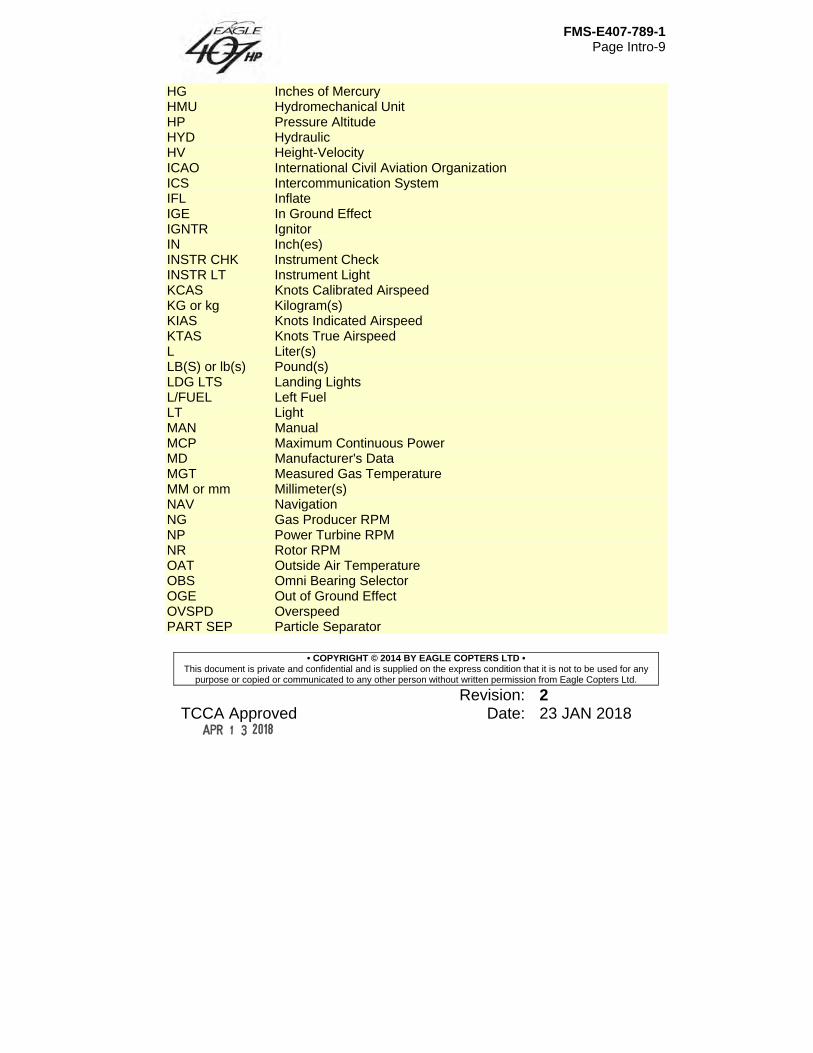
HG Inches of Mercury HMU Hydromechanical Unit HP Pressure Altitude HYD Hydraulic HV Height-Velocity ICAO International Civil Aviation Organization ICS Intercommunication System IFL Inflate IGE In Ground Effect IGNTR Ignitor IN Inch(es) INSTR CHK Instrument Check INSTR LT Instrument Light KCAS Knots Calibrated Airspeed KG or kg Kilogram(s) KIAS Knots Indicated Airspeed KTAS Knots True Airspeed L Liter(s) LB(S) or lb(s) Pound(s) LDG LTS Landing Lights L/FUEL Left Fuel LT Light MAN Manual MCP Maximum Continuous Power MD Manufacturer's Data MGT Measured Gas Temperature MM or mm Millimeter(s) NAV Navigation NG Gas Producer RPM NP Power Turbine RPM NR Rotor RPM OAT Outside Air Temperature OBS Omni Bearing Selector OGE Out of Ground Effect OVSPD Overspeed PART SEP Particle Separator
FMS-E407-789-1 Page Intro-10
• COPYRIGHT © 2014 BY EAGLE COPTERS LTD • This document is private and confidential and is supplied on the express condition that it is not to be used for any
purpose or copied or communicated to any other person without written permission from Eagle Copters Ltd.
Revision: 2 TCCA Approved Date: 23 JAN 2018
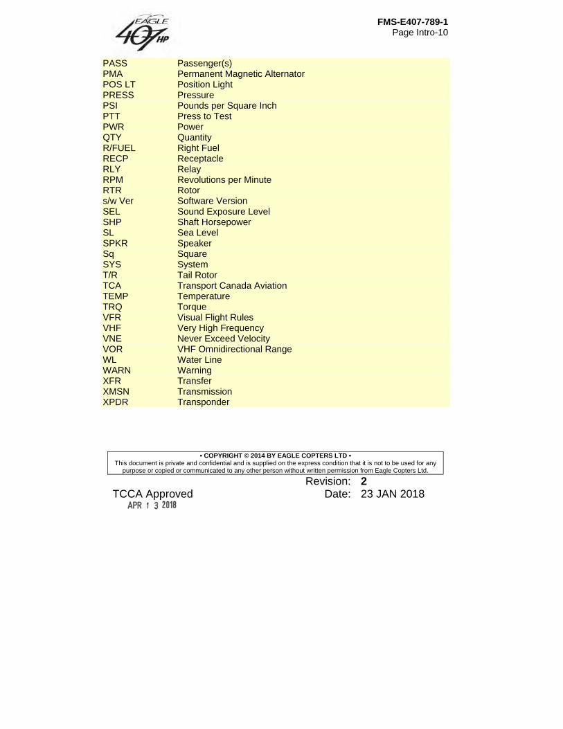
PASS Passenger(s) PMA Permanent Magnetic Alternator POS LT Position Light PRESS Pressure PSI Pounds per Square Inch PTT Press to Test PWR Power QTY Quantity R/FUEL Right Fuel RECP Receptacle RLY Relay RPM Revolutions per Minute RTR Rotor s/w Ver Software Version SEL Sound Exposure Level SHP Shaft Horsepower SL Sea Level SPKR Speaker Sq Square SYS System T/R Tail Rotor TCA Transport Canada Aviation TEMP Temperature TRQ Torque VFR Visual Flight Rules VHF Very High Frequency VNE Never Exceed Velocity VOR VHF Omnidirectional Range WL Water Line WARN Warning XFR Transfer XMSN Transmission XPDR Transponder
FMS-E407-789-1 Page 1-1
• COPYRIGHT © 2014 BY EAGLE COPTERS LTD • This document is private and confidential and is supplied on the express condition that it is not to be used for any
purpose or copied or communicated to any other person without written permission from Eagle Copters Ltd.
Revision: 1 TCCA Approved Date: 23 AUG 2016
Section 1 Limitations
Table of Contents
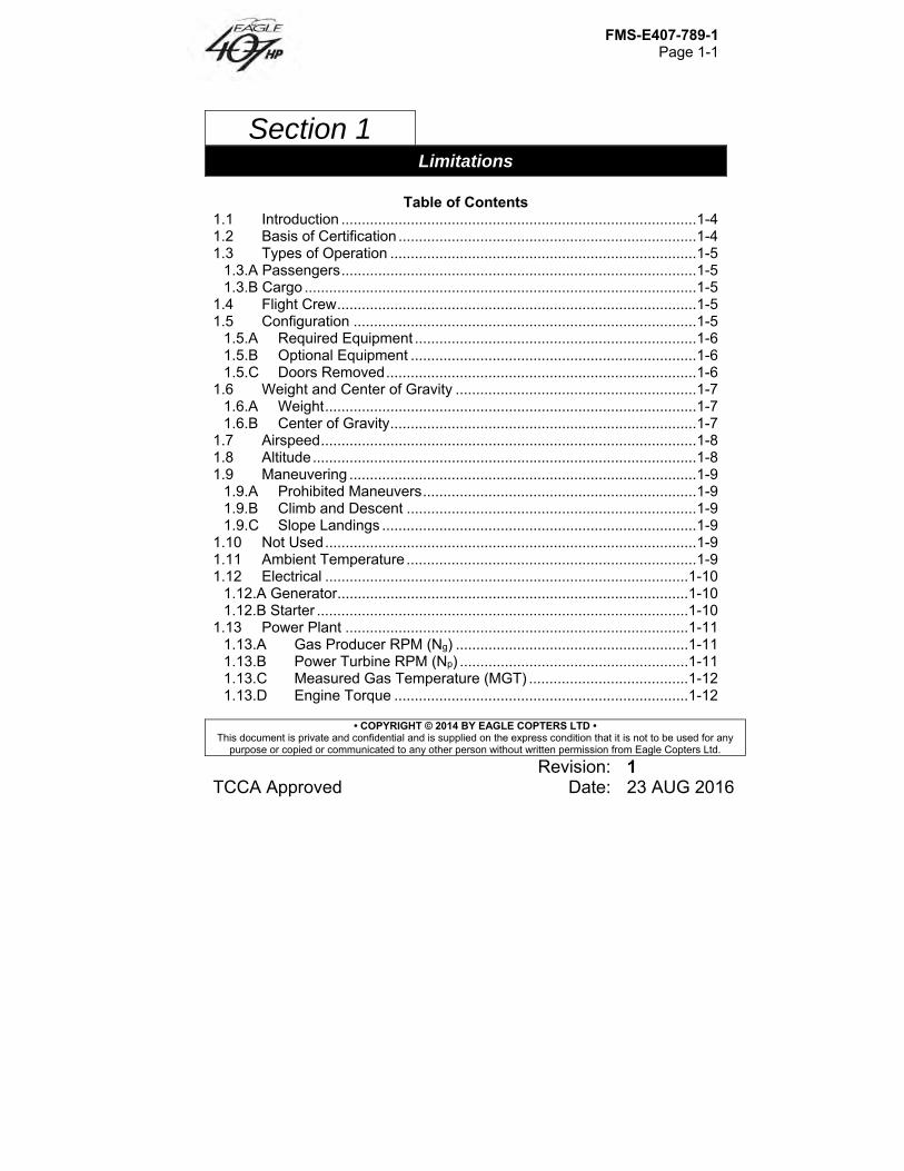
1.1 Introduction ....................................................................................... 1-4 1.2 Basis of Certification ......................................................................... 1-4 1.3 Types of Operation ........................................................................... 1-5
1.3.A Passengers ....................................................................................... 1-5 1.3.B Cargo ................................................................................................ 1-5
1.4 Flight Crew ........................................................................................ 1-5 1.5 Configuration .................................................................................... 1-5
1.5.A Required Equipment ..................................................................... 1-6 1.5.B Optional Equipment ...................................................................... 1-6 1.5.C Doors Removed ............................................................................ 1-6
1.6 Weight and Center of Gravity ........................................................... 1-7 1.6.A Weight ........................................................................................... 1-7 1.6.B Center of Gravity ........................................................................... 1-7
1.7 Airspeed ............................................................................................ 1-8 1.8 Altitude .............................................................................................. 1-8 1.9 Maneuvering ..................................................................................... 1-9
1.9.A Prohibited Maneuvers ................................................................... 1-9 1.9.B Climb and Descent ....................................................................... 1-9 1.9.C Slope Landings ............................................................................. 1-9
1.10 Not Used ........................................................................................... 1-9 1.11 Ambient Temperature ....................................................................... 1-9 1.12 Electrical ......................................................................................... 1-10
1.12.A Generator ...................................................................................... 1-10 1.12.B Starter ........................................................................................... 1-10
1.13 Power Plant .................................................................................... 1-11 1.13.A Gas Producer RPM (Ng) ......................................................... 1-11 1.13.B Power Turbine RPM (Np) ........................................................ 1-11 1.13.C Measured Gas Temperature (MGT) ....................................... 1-12 1.13.D Engine Torque ........................................................................ 1-12
FMS-E407-789-1 Page 1-2
• COPYRIGHT © 2014 BY EAGLE COPTERS LTD • This document is private and confidential and is supplied on the express condition that it is not to be used for any
purpose or copied or communicated to any other person without written permission from Eagle Copters Ltd.
Revision: 1 TCCA Approved Date: 23 AUG 2016
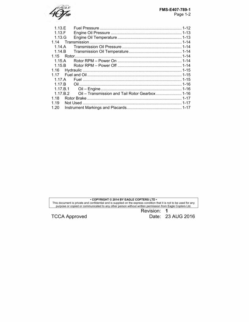
1.13.E Fuel Pressure ......................................................................... 1-12 1.13.F Engine Oil Pressure ............................................................... 1-13 1.13.G Engine Oil Temperature ......................................................... 1-13
1.14 Transmission .................................................................................. 1-14 1.14.A Transmission Oil Pressure ..................................................... 1-14 1.14.B Transmission Oil Temperature ............................................... 1-14
1.15 Rotor ............................................................................................... 1-14 1.15.A Rotor RPM – Power On ......................................................... 1-14 1.15.B Rotor RPM – Power Off ......................................................... 1-14
1.16 Hydraulic ........................................................................................ 1-15 1.17 Fuel and Oil .................................................................................... 1-15
1.17.A Fuel ........................................................................................ 1-15 1.17.B Oil ........................................................................................... 1-16 1.17.B.1 Oil – Engine ........................................................................ 1-16 1.17.B.2 Oil – Transmission and Tail Rotor Gearbox ....................... 1-16
1.18 Rotor Brake .................................................................................... 1-17 1.19 Not Used ........................................................................................ 1-17 1.20 Instrument Markings and Placards ................................................. 1-17
FMS-E407-789-1 Page 1-3
• COPYRIGHT © 2014 BY EAGLE COPTERS LTD • This document is private and confidential and is supplied on the express condition that it is not to be used for any
purpose or copied or communicated to any other person without written permission from Eagle Copters Ltd.
Revision: 1 TCCA Approved Date: 23 AUG 2016
List of Figures Figure 1-1 – Gross weight longitudinal center of gravity limits (Sheet 1 of 2) .. 1-18 Figure 1-1 – Gross weight longitudinal center of gravity limits (Sheet 2 of 2) .. 1-19 Figure 1-2 – Gross weight lateral center of gravity limits (Sheet 1 of 2) .......... 1-20 Figure 1-2 – Gross weight lateral center of gravity limits (Sheet 2 of 2) .......... 1-21 Figure 1-3 – Placards and Decals (Sheet 1 of 4) ............................................. 1-22 Figure 1-3 – Placards and Decals (Sheet 2 of 4) ............................................. 1-23 Figure 1-3 – Placards and Decals (Sheet 3 of 4) ............................................. 1-24 Figure 1-3 – Placards and Decals (Sheet 4 of 4) ............................................. 1-25 Figure 1-4 – Ambient air temperature limitations ............................................. 1-26 Figure 1-5 – Instrument Markings (Sheet 1 of 5) .............................................. 1-27 Figure 1-5 – Instrument Markings (Sheet 2 of 5) .............................................. 1-28 Figure 1-5 – Instrument Markings (Sheet 3 of 5) .............................................. 1-29 Figure 1-5 – Instrument Markings (Sheet 4 of 5) .............................................. 1-30 Figure 1-5 – Instrument Markings (Sheet 5 of 5) .............................................. 1-31
FMS-E407-789-1 Page 1-4
• COPYRIGHT © 2014 BY EAGLE COPTERS LTD • This document is private and confidential and is supplied on the express condition that it is not to be used for any
purpose or copied or communicated to any other person without written permission from Eagle Copters Ltd.
Revision: 1 TCCA Approved Date: 23 AUG 2016
Section 1 Limitations
1.1 Introduction Compliance with limitations in this section is required by appropriate operating rules. Anytime an operating limitation is exceeded, an appropriate entry shall be made in helicopter logbook. Entry shall state which limit was exceeded, duration of time, extreme value attained, and any additional information essential in determining maintenance action required. Intentional use of transient limits is prohibited. Torque events shall be recorded. A torque event is defined as a takeoff or lift, internal or external load (MD-E407-789-1). Landings shall be recorded. Run-on landings shall be recorded separately. A run-on landing is defined as one where there is forward ground travel of the helicopter greater than 3 feet with the weight on the skids.
1.2 Basis of Certification This helicopter is certified under FARs Parts 27 and 36, Appendix J. Additionally, it is approved under Canadian Airworthiness Manual Chapters 516 (ICAO Chapter 11) and 527, Sections 1093 (b) (1) (ii) and (iii), 1301-1, 1557 (c) (3), 1581 (e) and 1583 (h). Additionally, the certification basis of the Eagle 407HP modification includes an equivalent level of safety (ELOS) with respect to FAR 27.917 @ 27-11, FAR 27.923 @ 27-29, FAR 27.927 @ 27-23, and FAR 27.571 @ 27-26, and compliance has been demonstrated for 27.1195 at amendment 27-5.
FMS-E407-789-1 Page 1-5
• COPYRIGHT © 2014 BY EAGLE COPTERS LTD • This document is private and confidential and is supplied on the express condition that it is not to be used for any
purpose or copied or communicated to any other person without written permission from Eagle Copters Ltd.
Revision: 1 TCCA Approved Date: 23 AUG 2016
1.3 Types of Operation
1.3.A Passengers Basic configured helicopter is approved for seven place seating and is certified for land operations under day or night VFR non-icing conditions.
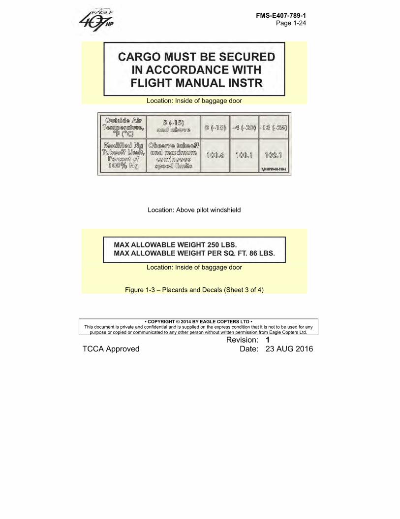
1.3.B Cargo The maximum allowable cabin deck loading for cargo is 75 pounds per square foot (3.7 kg per 100 cm2). The maximum allowable baggage compartment deck loading is 86 pounds per square foot (4.2 kg per 100 cm2) with a maximum allowable weight of 250 pounds (113.4 kg). Refer to MD-E407-789-1 for cargo restraint and tie-down locations. Cargo must be properly secured by tie-down devices to prevent the load from shifting under anticipated flight and ground operations. If the mission requires both passengers and cargo to be transported together, the cargo must be loaded and secured so that it does not obstruct passenger access to exits.
1.4 Flight Crew Minimum flight crew consists of one pilot who shall operate helicopter from the right crew seat. Left crew seat may be used for an additional pilot for VFR day and night operations when approved dual controls are installed.
1.5 Configuration The Eagle 407HP modification is only eligible on Bell 407 S/N 53000 to 54299.
FMS-E407-789-1 Page 1-6
• COPYRIGHT © 2014 BY EAGLE COPTERS LTD • This document is private and confidential and is supplied on the express condition that it is not to be used for any
purpose or copied or communicated to any other person without written permission from Eagle Copters Ltd.
Revision: 1 TCCA Approved Date: 23 AUG 2016
1.5.A Required Equipment A functional flashlight is required for night flights. A functional Outside Air Temperature gauge. Bell Kit 407-706-020 for gross weight increase to 5250 lb FADEC system software shall be version 10.0.
1.5.B Optional Equipment The snow deflector kit (BHT-407-FMS-4) shall be installed when conducting flight operations in falling and/or blowing snow. With the Eagle 407HP modification, Cargo Hook Kit P/N 206-706-341, Cargo Hook Retrofit Kit P/N 407-704-023 and RFMS BHT-407-FMS-5 are still applicable. Refer to appropriate flight manual supplement(s) (FMS) for additional limitations, procedures, and performance data required for optional equipment.
1.5.C Doors Removed NOTE
Indicated altitude may be up to 100 feet lower than actual altitude with crew door(s) removed.
Flight with any combination of doors removed is approved. With litter door removed, left passenger door shall be removed. Refer to Airspeed limitations. With door(s) removed, determine weight change and adjust ballast if necessary. Refer to Section 5.
FMS-E407-789-1 Page 1-7
• COPYRIGHT © 2014 BY EAGLE COPTERS LTD • This document is private and confidential and is supplied on the express condition that it is not to be used for any
purpose or copied or communicated to any other person without written permission from Eagle Copters Ltd.
Revision: 1 TCCA Approved Date: 23 AUG 2016
NOTE
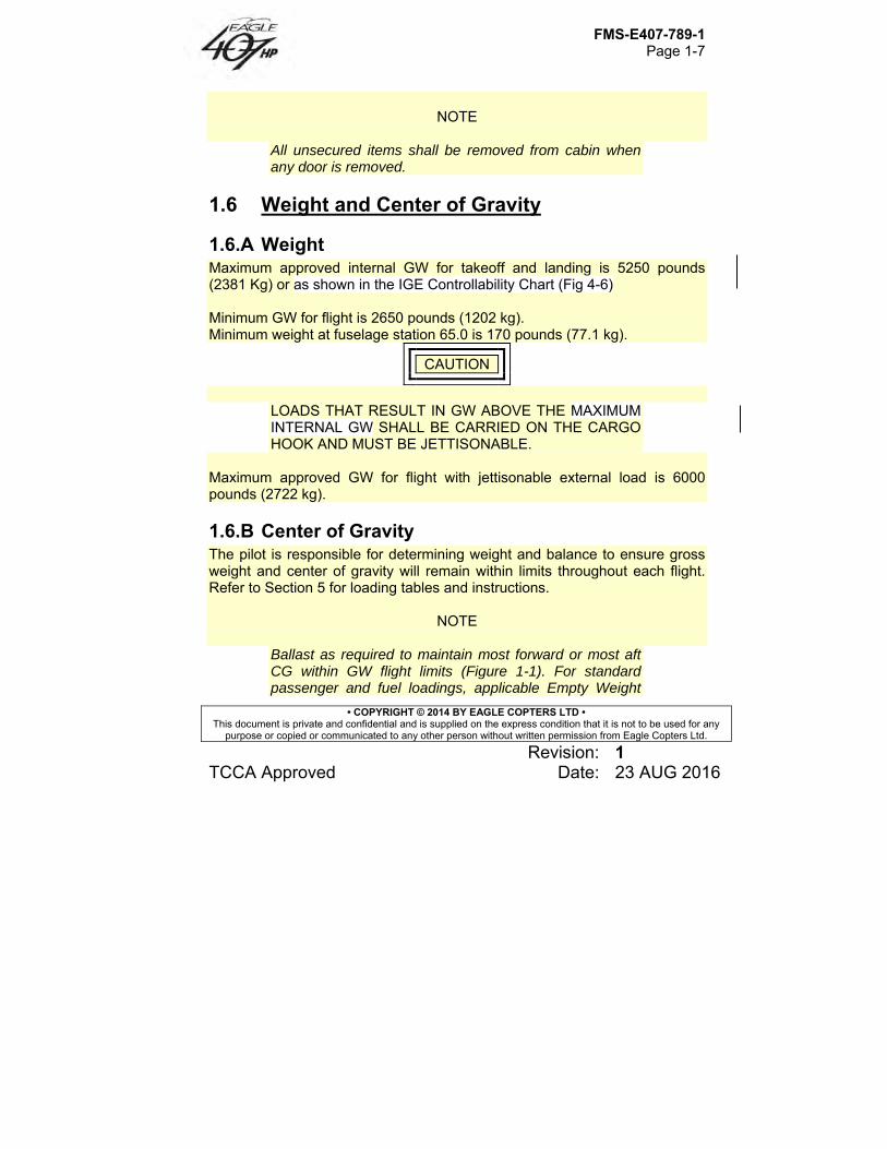
All unsecured items shall be removed from cabin when any door is removed.
1.6 Weight and Center of Gravity
1.6.A Weight Maximum approved internal GW for takeoff and landing is 5250 pounds (2381 Kg) or as shown in the IGE Controllability Chart (Fig 4-6) Minimum GW for flight is 2650 pounds (1202 kg). Minimum weight at fuselage station 65.0 is 170 pounds (77.1 kg).
CAUTION
LOADS THAT RESULT IN GW ABOVE THE MAXIMUM INTERNAL GW SHALL BE CARRIED ON THE CARGO HOOK AND MUST BE JETTISONABLE.
Maximum approved GW for flight with jettisonable external load is 6000 pounds (2722 kg).
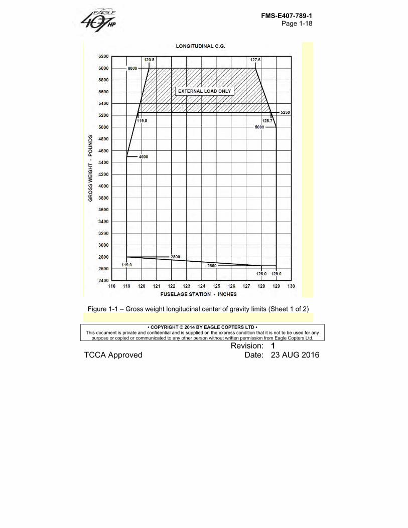
1.6.B Center of Gravity The pilot is responsible for determining weight and balance to ensure gross weight and center of gravity will remain within limits throughout each flight. Refer to Section 5 for loading tables and instructions.
NOTE
Ballast as required to maintain most forward or most aft CG within GW flight limits (Figure 1-1). For standard passenger and fuel loadings, applicable Empty Weight
FMS-E407-789-1 Page 1-8
• COPYRIGHT © 2014 BY EAGLE COPTERS LTD • This document is private and confidential and is supplied on the express condition that it is not to be used for any
purpose or copied or communicated to any other person without written permission from Eagle Copters Ltd.
Revision: 1 TCCA Approved Date: 23 AUG 2016
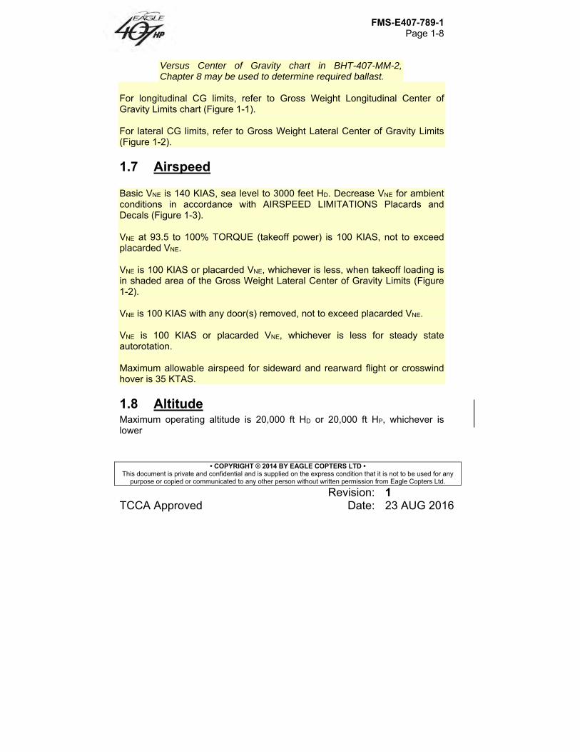
Versus Center of Gravity chart in BHT-407-MM-2, Chapter 8 may be used to determine required ballast.
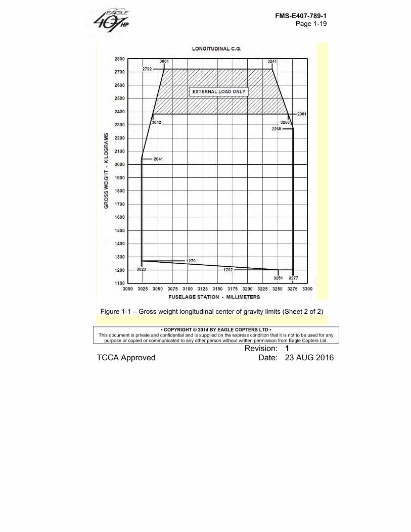
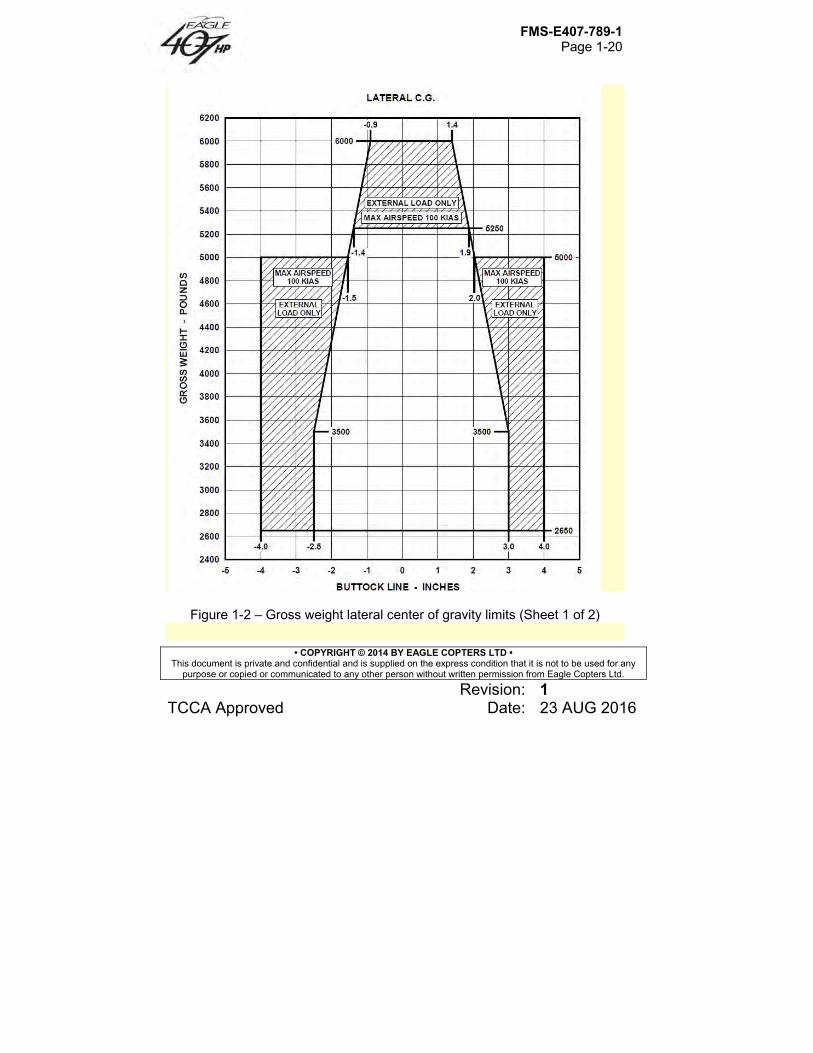
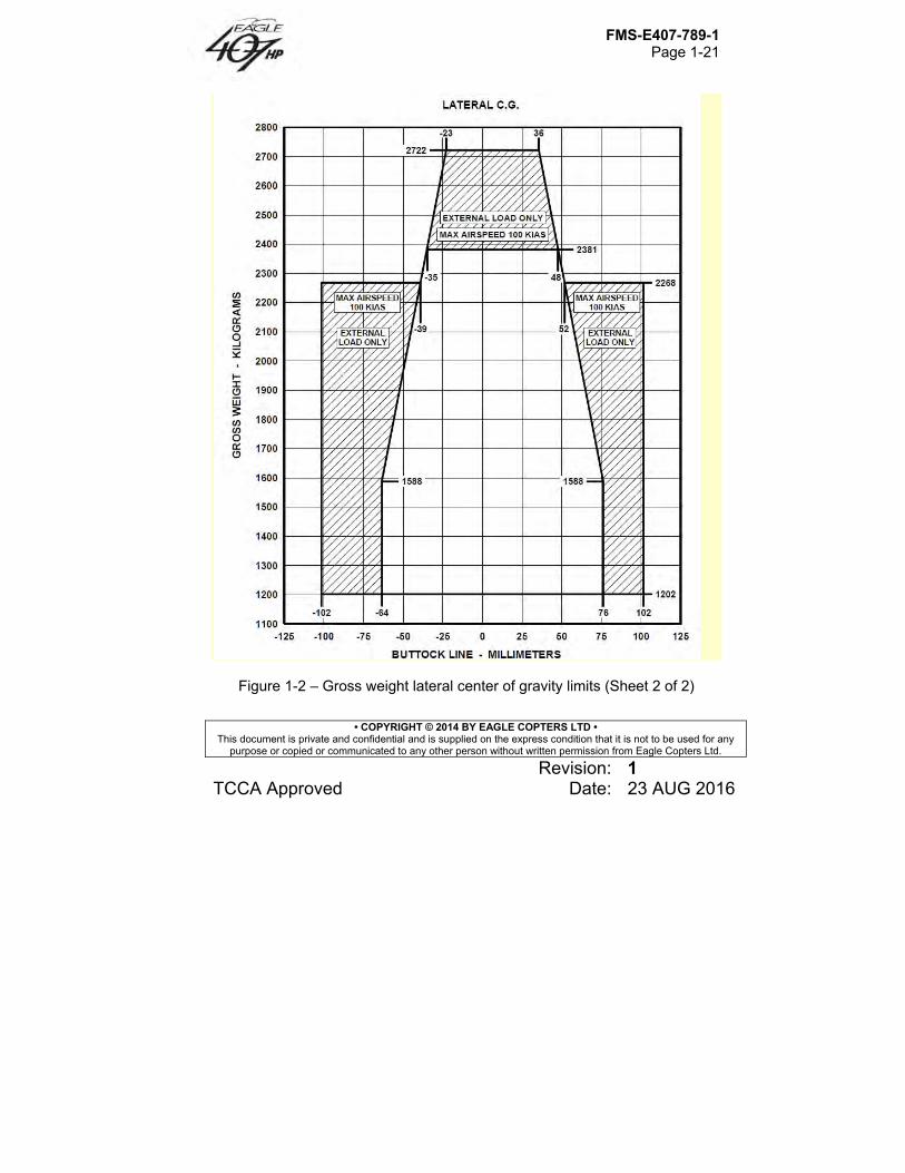
For longitudinal CG limits, refer to Gross Weight Longitudinal Center of Gravity Limits chart (Figure 1-1). For lateral CG limits, refer to Gross Weight Lateral Center of Gravity Limits (Figure 1-2).
1.7 Airspeed Basic VNE is 140 KIAS, sea level to 3000 feet HD. Decrease VNE for ambient conditions in accordance with AIRSPEED LIMITATIONS Placards and Decals (Figure 1-3). VNE at 93.5 to 100% TORQUE (takeoff power) is 100 KIAS, not to exceed placarded VNE. VNE is 100 KIAS or placarded VNE, whichever is less, when takeoff loading is in shaded area of the Gross Weight Lateral Center of Gravity Limits (Figure 1-2). VNE is 100 KIAS with any door(s) removed, not to exceed placarded VNE. VNE is 100 KIAS or placarded VNE, whichever is less for steady state autorotation. Maximum allowable airspeed for sideward and rearward flight or crosswind hover is 35 KTAS.
1.8 Altitude Maximum operating altitude is 20,000 ft HD or 20,000 ft HP, whichever is lower
FMS-E407-789-1 Page 1-9
• COPYRIGHT © 2014 BY EAGLE COPTERS LTD • This document is private and confidential and is supplied on the express condition that it is not to be used for any
purpose or copied or communicated to any other person without written permission from Eagle Copters Ltd.
Revision: 1 TCCA Approved Date: 23 AUG 2016
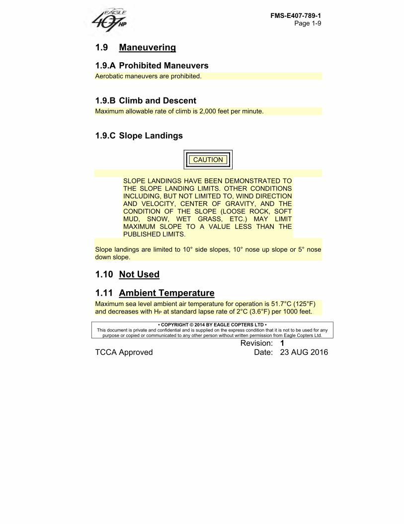
1.9 Maneuvering
1.9.A Prohibited Maneuvers Aerobatic maneuvers are prohibited.
1.9.B Climb and Descent Maximum allowable rate of climb is 2,000 feet per minute.
1.9.C Slope Landings
CAUTION
SLOPE LANDINGS HAVE BEEN DEMONSTRATED TO THE SLOPE LANDING LIMITS. OTHER CONDITIONS INCLUDING, BUT NOT LIMITED TO, WIND DIRECTION AND VELOCITY, CENTER OF GRAVITY, AND THE CONDITION OF THE SLOPE (LOOSE ROCK, SOFT MUD, SNOW, WET GRASS, ETC.) MAY LIMIT MAXIMUM SLOPE TO A VALUE LESS THAN THE PUBLISHED LIMITS.
Slope landings are limited to 10° side slopes, 10° nose up slope or 5° nose down slope.
1.10 Not Used
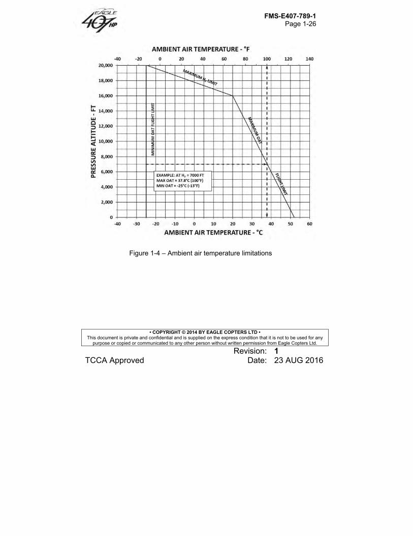
1.11 Ambient Temperature Maximum sea level ambient air temperature for operation is 51.7°C (125°F) and decreases with HP at standard lapse rate of 2°C (3.6°F) per 1000 feet.
FMS-E407-789-1 Page 1-10
• COPYRIGHT © 2014 BY EAGLE COPTERS LTD • This document is private and confidential and is supplied on the express condition that it is not to be used for any
purpose or copied or communicated to any other person without written permission from Eagle Copters Ltd.
Revision: 1 TCCA Approved Date: 23 AUG 2016
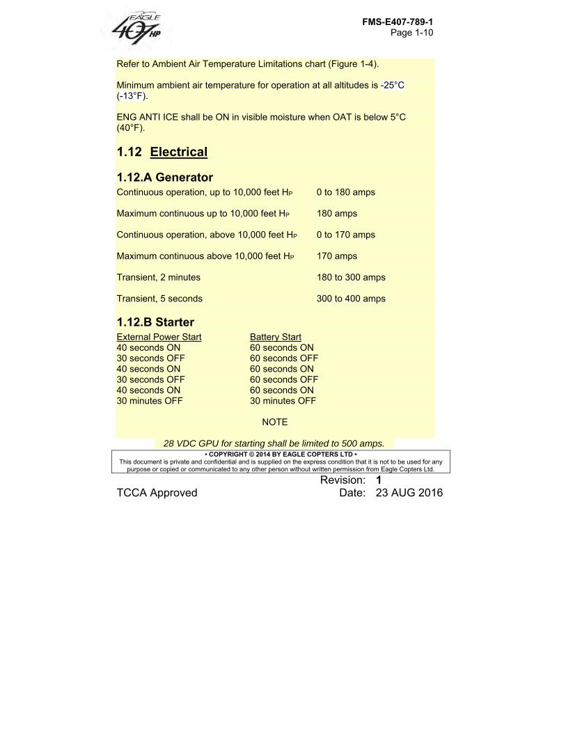
Refer to Ambient Air Temperature Limitations chart (Figure 1-4). Minimum ambient air temperature for operation at all altitudes is -25°C (-13°F). ENG ANTI ICE shall be ON in visible moisture when OAT is below 5°C (40°F).
1.12 Electrical
1.12.A Generator Continuous operation, up to 10,000 feet HP 0 to 180 amps Maximum continuous up to 10,000 feet HP 180 amps Continuous operation, above 10,000 feet HP 0 to 170 amps Maximum continuous above 10,000 feet HP 170 amps Transient, 2 minutes 180 to 300 amps Transient, 5 seconds 300 to 400 amps
1.12.B Starter External Power Start Battery Start 40 seconds ON 60 seconds ON 30 seconds OFF 60 seconds OFF 40 seconds ON 60 seconds ON 30 seconds OFF 60 seconds OFF 40 seconds ON 60 seconds ON 30 minutes OFF 30 minutes OFF
NOTE
28 VDC GPU for starting shall be limited to 500 amps.
FMS-E407-789-1 Page 1-11
• COPYRIGHT © 2014 BY EAGLE COPTERS LTD • This document is private and confidential and is supplied on the express condition that it is not to be used for any
purpose or copied or communicated to any other person without written permission from Eagle Copters Ltd.
Revision: 1 TCCA Approved Date: 23 AUG 2016
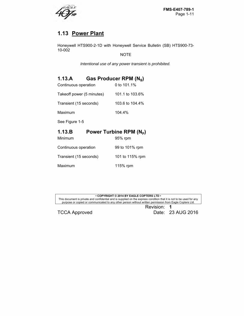
1.13 Power Plant Honeywell HTS900-2-1D with Honeywell Service Bulletin (SB) HTS900-73-10-002
NOTE
Intentional use of any power transient is prohibited.
1.13.A Gas Producer RPM (Ng) Continuous operation 0 to 101.1% Takeoff power (5 minutes) 101.1 to 103.6% Transient (15 seconds) 103.6 to 104.4% Maximum 104.4% See Figure 1-5
1.13.B Power Turbine RPM (Np) Minimum 95% rpm Continuous operation 99 to 101% rpm Transient (15 seconds) 101 to 115% rpm Maximum 115% rpm
FMS-E407-789-1 Page 1-12
• COPYRIGHT © 2014 BY EAGLE COPTERS LTD • This document is private and confidential and is supplied on the express condition that it is not to be used for any
purpose or copied or communicated to any other person without written permission from Eagle Copters Ltd.
Revision: 1 TCCA Approved Date: 23 AUG 2016
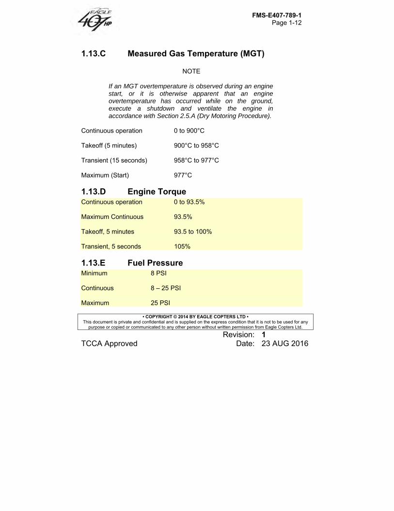
1.13.C Measured Gas Temperature (MGT)
NOTE
If an MGT overtemperature is observed during an engine start, or it is otherwise apparent that an engine overtemperature has occurred while on the ground, execute a shutdown and ventilate the engine in accordance with Section 2.5.A (Dry Motoring Procedure).
Continuous operation 0 to 900°C
Takeoff (5 minutes) 900°C to 958°C
Transient (15 seconds) 958°C to 977°C
Maximum (Start) 977°C
1.13.D Engine Torque Continuous operation 0 to 93.5% Maximum Continuous 93.5% Takeoff, 5 minutes 93.5 to 100% Transient, 5 seconds 105%
1.13.E Fuel Pressure Minimum 8 PSI Continuous 8 – 25 PSI Maximum 25 PSI
FMS-E407-789-1 Page 1-13
• COPYRIGHT © 2014 BY EAGLE COPTERS LTD • This document is private and confidential and is supplied on the express condition that it is not to be used for any
purpose or copied or communicated to any other person without written permission from Eagle Copters Ltd.
Revision: 1 TCCA Approved Date: 23 AUG 2016
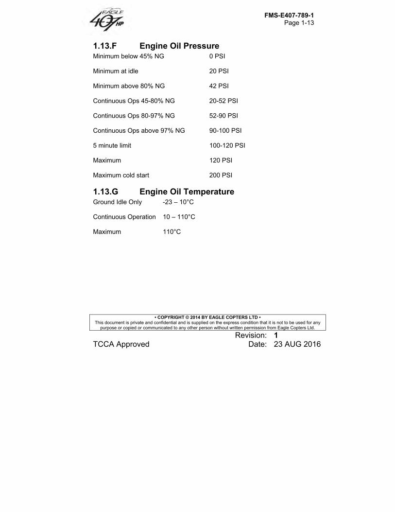
1.13.F Engine Oil Pressure Minimum below 45% NG 0 PSI Minimum at idle 20 PSI Minimum above 80% NG 42 PSI Continuous Ops 45-80% NG 20-52 PSI Continuous Ops 80-97% NG 52-90 PSI Continuous Ops above 97% NG 90-100 PSI 5 minute limit 100-120 PSI Maximum 120 PSI Maximum cold start 200 PSI
1.13.G Engine Oil Temperature Ground Idle Only -23 – 10°C Continuous Operation 10 – 110°C Maximum 110°C
FMS-E407-789-1 Page 1-14
• COPYRIGHT © 2014 BY EAGLE COPTERS LTD • This document is private and confidential and is supplied on the express condition that it is not to be used for any
purpose or copied or communicated to any other person without written permission from Eagle Copters Ltd.
Revision: 1 TCCA Approved Date: 23 AUG 2016
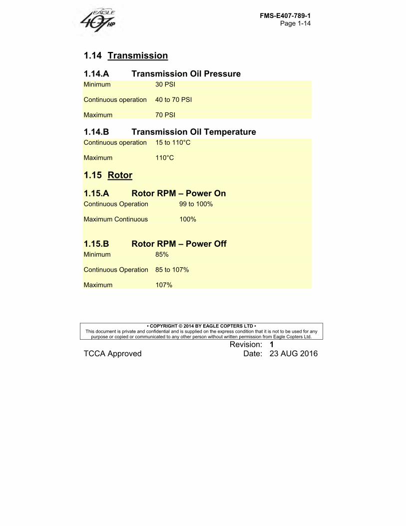
1.14 Transmission
1.14.A Transmission Oil Pressure Minimum 30 PSI Continuous operation 40 to 70 PSI Maximum 70 PSI
1.14.B Transmission Oil Temperature Continuous operation 15 to 110°C Maximum 110°C
1.15 Rotor
1.15.A Rotor RPM – Power On Continuous Operation 99 to 100% Maximum Continuous 100%
1.15.B Rotor RPM – Power Off Minimum 85% Continuous Operation 85 to 107% Maximum 107%
FMS-E407-789-1 Page 1-15
• COPYRIGHT © 2014 BY EAGLE COPTERS LTD • This document is private and confidential and is supplied on the express condition that it is not to be used for any
purpose or copied or communicated to any other person without written permission from Eagle Copters Ltd.
Revision: 1 TCCA Approved Date: 23 AUG 2016
CAUTION
FOR AUTOROTATIVE TRAINING, MAINTAIN STEADY STATE NR ABOVE 90%.
1.16 Hydraulic Hydraulic fluid type MIL-H-5606 (NATO H-515) shall be used at all ambient temperatures.
1.17 Fuel and Oil
1.17.A Fuel Fuel conforming to following specifications may be used at all ambient temperatures: ASTM-D-6615, Jet B MIL-DTL-5624, Grade JP-4 (NATO F-40) Fuels conforming to following specifications are limited to ambient temperatures of -32°C (-25°F) and above: ASTM-D-1655, Jet A or A-1 MIL-DTL-5624, Grade JP-5 (NATO F-44) MIL-DTL-83133, Grade JP-8 (NATO F-34)
FMS-E407-789-1 Page 1-16
• COPYRIGHT © 2014 BY EAGLE COPTERS LTD • This document is private and confidential and is supplied on the express condition that it is not to be used for any
purpose or copied or communicated to any other person without written permission from Eagle Copters Ltd.
Revision: 1 TCCA Approved Date: 23 AUG 2016
1.17.B Oil
1.17.B.1 Oil – Engine Oil conforming MIL-PRF-23699 (NATO O-156) is limited to ambient temperatures above -40°C (-40°F).
NOTE
Refer to Honeywell Light Maintenance Manual for HTS900-2-1D and MD-E407-789-1 for approved oils and mixing of oils of different brands, types, and manufacturers.
1.17.B.2 Oil – Transmission and Tail Rotor Gearbox
NOTE
It is recommended DOD-PRF-85734 oil be used in transmission and tail rotor gearbox to maximum extent allowed by temperature limitations.
Oil conforming to DOD-PRF-85734 is limited to ambient temperatures above -40°C (-40°F). Oil conforming to MIL-PRF-7808 (NATO O-148) is limited to ambient temperatures below -18°C (0°F).
FMS-E407-789-1 Page 1-17
• COPYRIGHT © 2014 BY EAGLE COPTERS LTD • This document is private and confidential and is supplied on the express condition that it is not to be used for any
purpose or copied or communicated to any other person without written permission from Eagle Copters Ltd.
Revision: 1 TCCA Approved Date: 23 AUG 2016
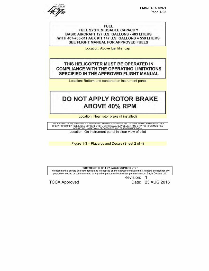
1.18 Rotor Brake Rotor brake application is limited to ground operation after engine has been shut down and NR has decreased to 40% or lower. For emergency stops, apply rotor brake any time after engine is shut down. Engine starts with rotor brake engaged are prohibited.
1.19 Not Used
1.20 Instrument Markings and Placards
Refer to Figure 1-3 for Placards and Decals. Refer to Figure 1-5 for Instrument Markings. Illustrations shown in Figure 1-5 are artist representations and may or may not depict actual approved instruments due to printing limitations. Instrument operating ranges and limits shall agree with those presented in this section.
FMS-E407-789-1 Page 1-18
• COPYRIGHT © 2014 BY EAGLE COPTERS LTD • This document is private and confidential and is supplied on the express condition that it is not to be used for any
purpose or copied or communicated to any other person without written permission from Eagle Copters Ltd.
Revision: 1 TCCA Approved Date: 23 AUG 2016
Figure 1-1 – Gross weight longitudinal center of gravity limits (Sheet 1 of 2)
FMS-E407-789-1 Page 1-19
• COPYRIGHT © 2014 BY EAGLE COPTERS LTD • This document is private and confidential and is supplied on the express condition that it is not to be used for any
purpose or copied or communicated to any other person without written permission from Eagle Copters Ltd.
Revision: 1 TCCA Approved Date: 23 AUG 2016
Figure 1-1 – Gross weight longitudinal center of gravity limits (Sheet 2 of 2)
FMS-E407-789-1 Page 1-20
• COPYRIGHT © 2014 BY EAGLE COPTERS LTD • This document is private and confidential and is supplied on the express condition that it is not to be used for any
purpose or copied or communicated to any other person without written permission from Eagle Copters Ltd.
Revision: 1 TCCA Approved Date: 23 AUG 2016
Figure 1-2 – Gross weight lateral center of gravity limits (Sheet 1 of 2)
FMS-E407-789-1 Page 1-21
• COPYRIGHT © 2014 BY EAGLE COPTERS LTD • This document is private and confidential and is supplied on the express condition that it is not to be used for any
purpose or copied or communicated to any other person without written permission from Eagle Copters Ltd.
Revision: 1 TCCA Approved Date: 23 AUG 2016
Figure 1-2 – Gross weight lateral center of gravity limits (Sheet 2 of 2)
FMS-E407-789-1 Page 1-22
• COPYRIGHT © 2014 BY EAGLE COPTERS LTD • This document is private and confidential and is supplied on the express condition that it is not to be used for any
purpose or copied or communicated to any other person without written permission from Eagle Copters Ltd.
Revision: 1 TCCA Approved Date: 23 AUG 2016
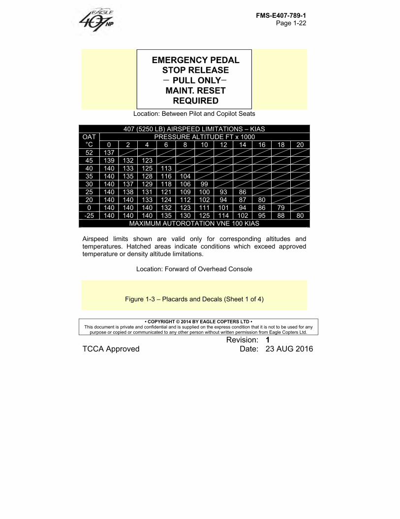
Location: Between Pilot and Copilot Seats
407 (5250 LB) AIRSPEED LIMITATIONS – KIAS
OAT °C
PRESSURE ALTITUDE FT x 1000 0 2 4 6 8 10 12 14 16 18 20
52 137 45 139 132 123 40 140 133 125 113 35 140 135 128 116 104 30 140 137 129 118 106 99 25 140 138 131 121 109 100 93 86 20 140 140 133 124 112 102 94 87 80 0 140 140 140 132 123 111 101 94 86 79
-25 140 140 140 135 130 125 114 102 95 88 80 MAXIMUM AUTOROTATION VNE 100 KIAS
Airspeed limits shown are valid only for corresponding altitudes and temperatures. Hatched areas indicate conditions which exceed approved temperature or density altitude limitations.
Location: Forward of Overhead Console
Figure 1-3 – Placards and Decals (Sheet 1 of 4)
FMS-E407-789-1 Page 1-23
• COPYRIGHT © 2014 BY EAGLE COPTERS LTD • This document is private and confidential and is supplied on the express condition that it is not to be used for any
purpose or copied or communicated to any other person without written permission from Eagle Copters Ltd.
Revision: 1 TCCA Approved Date: 23 AUG 2016
Location: Above fuel filler cap
Location: Bottom and centered on instrument panel
Location: Near rotor brake (if installed)
THIS AIRCRAFT IS EQUIPPED WITH A HONEYWELL HTS900-2-1D ENGINE AND IS APPROVED FOR DAY/NIGHT VFR OPERATIONS ONLY. SEE EAGLE COPTERS LTD FLIGHT MANUAL SUPPLEMENT FMS-E407-789-1 FOR MODIFIED
OPERATING LIMITATIONS, PROCEDURES AND PERFORMANCE DATA.
Location: On instrument panel in clear view of pilot
Figure 1-3 – Placards and Decals (Sheet 2 of 4)
FMS-E407-789-1 Page 1-24
• COPYRIGHT © 2014 BY EAGLE COPTERS LTD • This document is private and confidential and is supplied on the express condition that it is not to be used for any
purpose or copied or communicated to any other person without written permission from Eagle Copters Ltd.
Revision: 1 TCCA Approved Date: 23 AUG 2016
Location: Inside of baggage door
Location: Above pilot windshield
Location: Inside of baggage door
Figure 1-3 – Placards and Decals (Sheet 3 of 4)
FMS-E407-789-1 Page 1-25
• COPYRIGHT © 2014 BY EAGLE COPTERS LTD • This document is private and confidential and is supplied on the express condition that it is not to be used for any
purpose or copied or communicated to any other person without written permission from Eagle Copters Ltd.
Revision: 1 TCCA Approved Date: 23 AUG 2016
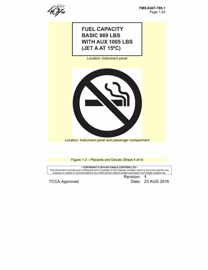
Location: Instrument panel
Location: Instrument panel and passenger compartment
Figure 1-3 – Placards and Decals (Sheet 4 of 4)
FMS-E407-789-1 Page 1-26
• COPYRIGHT © 2014 BY EAGLE COPTERS LTD • This document is private and confidential and is supplied on the express condition that it is not to be used for any
purpose or copied or communicated to any other person without written permission from Eagle Copters Ltd.
Revision: 1 TCCA Approved Date: 23 AUG 2016
Figure 1-4 – Ambient air temperature limitations
FMS-E407-789-1 Page 1-27
• COPYRIGHT © 2014 BY EAGLE COPTERS LTD • This document is private and confidential and is supplied on the express condition that it is not to be used for any
purpose or copied or communicated to any other person without written permission from Eagle Copters Ltd.
Revision: 1 TCCA Approved Date: 23 AUG 2016
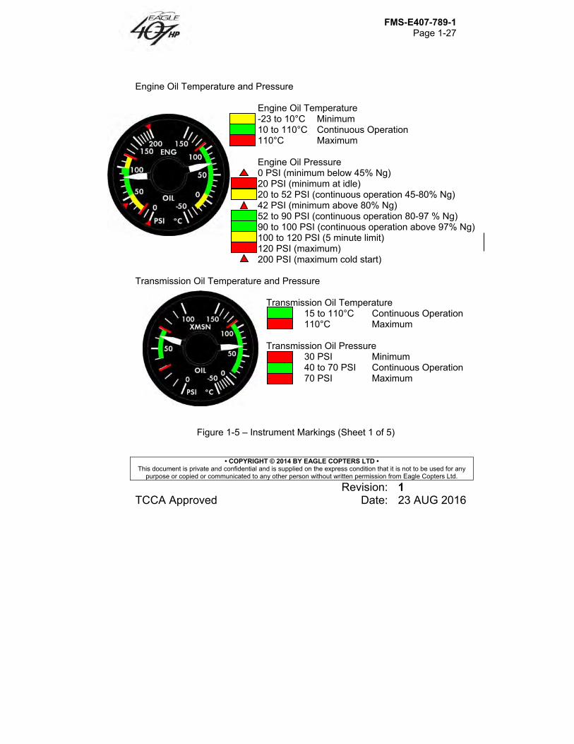
Engine Oil Temperature and Pressure Engine Oil Temperature -23 to 10°C Minimum 10 to 110°C Continuous Operation 110°C Maximum Engine Oil Pressure 0 PSI (minimum below 45% Ng) 20 PSI (minimum at idle) 20 to 52 PSI (continuous operation 45-80% Ng) 42 PSI (minimum above 80% Ng) 52 to 90 PSI (continuous operation 80-97 % Ng) 90 to 100 PSI (continuous operation above 97% Ng) 100 to 120 PSI (5 minute limit) 120 PSI (maximum) 200 PSI (maximum cold start) Transmission Oil Temperature and Pressure Transmission Oil Temperature 15 to 110°C Continuous Operation 110°C Maximum Transmission Oil Pressure 30 PSI Minimum 40 to 70 PSI Continuous Operation 70 PSI Maximum
Figure 1-5 – Instrument Markings (Sheet 1 of 5)
FMS-E407-789-1 Page 1-28
• COPYRIGHT © 2014 BY EAGLE COPTERS LTD • This document is private and confidential and is supplied on the express condition that it is not to be used for any
purpose or copied or communicated to any other person without written permission from Eagle Copters Ltd.
Revision: 1 TCCA Approved Date: 23 AUG 2016
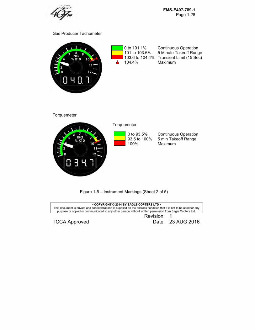
Gas Producer Tachometer 0 to 101.1% Continuous Operation 101 to 103.6% 5 Minute Takeoff Range 103.6 to 104.4% Transient Limit (15 Sec) 104.4% Maximum
Torquemeter Torquemeter 0 to 93.5% Continuous Operation 93.5 to 100% 5 min Takeoff Range 100% Maximum
Figure 1-5 – Instrument Markings (Sheet 2 of 5)
FMS-E407-789-1 Page 1-29
• COPYRIGHT © 2014 BY EAGLE COPTERS LTD • This document is private and confidential and is supplied on the express condition that it is not to be used for any
purpose or copied or communicated to any other person without written permission from Eagle Copters Ltd.
Revision: 1 TCCA Approved Date: 23 AUG 2016
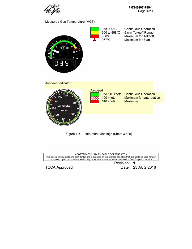
Measured Gas Temperature (MGT) 0 to 900°C Continuous Operation
900 to 958°C 5 min Takeoff Range 958°C Maximum for Takeoff
977°C Maximum for Start
Airspeed Indicator Airspeed 0 to 140 knots Continuous Operation 100 knots Maximum for autorotation 140 knots Maximum
Figure 1-5 – Instrument Markings (Sheet 3 of 5)
FMS-E407-789-1 Page 1-30
• COPYRIGHT © 2014 BY EAGLE COPTERS LTD • This document is private and confidential and is supplied on the express condition that it is not to be used for any
purpose or copied or communicated to any other person without written permission from Eagle Copters Ltd.
Revision: 1 TCCA Approved Date: 23 AUG 2016
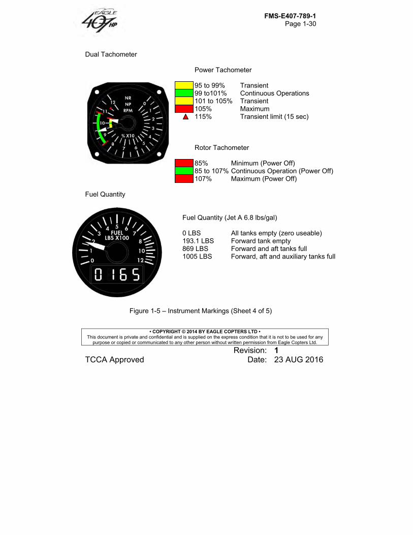
Dual Tachometer Power Tachometer 95 to 99% Transient 99 to101% Continuous Operations 101 to 105% Transient 105% Maximum 115% Transient limit (15 sec) Rotor Tachometer 85% Minimum (Power Off) 85 to 107% Continuous Operation (Power Off) 107% Maximum (Power Off)
Fuel Quantity Fuel Quantity (Jet A 6.8 lbs/gal) 0 LBS All tanks empty (zero useable) 193.1 LBS Forward tank empty 869 LBS Forward and aft tanks full 1005 LBS Forward, aft and auxiliary tanks full
Figure 1-5 – Instrument Markings (Sheet 4 of 5)
FMS-E407-789-1 Page 1-31
• COPYRIGHT © 2014 BY EAGLE COPTERS LTD • This document is private and confidential and is supplied on the express condition that it is not to be used for any
purpose or copied or communicated to any other person without written permission from Eagle Copters Ltd.
Revision: 1 TCCA Approved Date: 23 AUG 2016
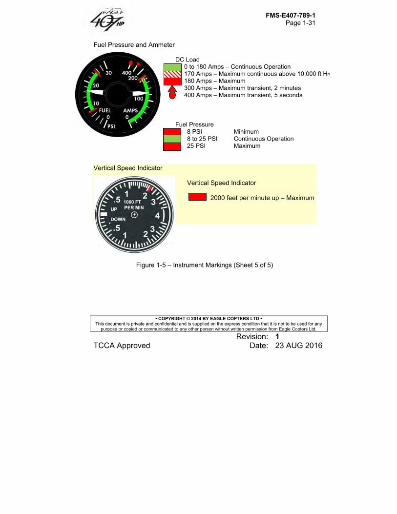
Fuel Pressure and Ammeter DC Load 0 to 180 Amps – Continuous Operation 170 Amps – Maximum continuous above 10,000 ft HP 180 Amps – Maximum 300 Amps – Maximum transient, 2 minutes 400 Amps – Maximum transient, 5 seconds Fuel Pressure 8 PSI Minimum 8 to 25 PSI Continuous Operation 25 PSI Maximum Vertical Speed Indicator Vertical Speed Indicator 2000 feet per minute up – Maximum
Figure 1-5 – Instrument Markings (Sheet 5 of 5)

FMS-E407-789-1 Page 2-1
• COPYRIGHT © 2014 BY EAGLE COPTERS LTD • This document is private and confidential and is supplied on the express condition that it is not to be used for any
purpose or copied or communicated to any other person without written permission from Eagle Copters Ltd.
Revision: 1 TCCA Approved Date: 23 AUG 2016
Section 2 Normal Procedures
Table of Contents
2.1 Introduction ........................................................................................ 2-3
2.1.A Cold Weather Operations .............................................................. 2-3 2.1.B Hot Weather Operations ................................................................ 2-4
2.2 Flight Planning ................................................................................... 2-4 2.3 Preflight Check ................................................................................... 2-5
2.3.A Before Exterior Check .................................................................... 2-5 2.3.B Exterior Check ................................................................................ 2-5
2.4 Interior and Prestart Check .............................................................. 2-13 2.5 Engine Start ..................................................................................... 2-18
2.5.A Dry Motoring Run – No Ignition .................................................... 2-22 2.5.B Wet Motoring Run – No Ignition ................................................... 2-23
2.6 Systems Check ................................................................................ 2-24 2.6.A Preliminary Hydraulic Systems Check ......................................... 2-24 2.6.B Deleted ......................................................................................... 2-25 2.6.C Engine Run-Up ............................................................................. 2-25 2.6.D Hydraulic Systems Check ............................................................ 2-26
2.7 Before Takeoff.................................................................................. 2-27 2.8 Takeoff ............................................................................................. 2-29 2.9 In-Flight Operations ......................................................................... 2-29 2.10 Descent and Landing ....................................................................... 2-30 2.11 Engine Shutdown ............................................................................. 2-31 2.12 Postflight Check ............................................................................... 2-35
FMS-E407-789-1 Page 2-2
• COPYRIGHT © 2014 BY EAGLE COPTERS LTD • This document is private and confidential and is supplied on the express condition that it is not to be used for any
purpose or copied or communicated to any other person without written permission from Eagle Copters Ltd.
Revision: 1 TCCA Approved Date: 23 AUG 2016
List of Figures
Figure 2-1 – Preflight Check Sequence ....................................................... 2-36

FMS-E407-789-1 Page 2-3
• COPYRIGHT © 2014 BY EAGLE COPTERS LTD • This document is private and confidential and is supplied on the express condition that it is not to be used for any
purpose or copied or communicated to any other person without written permission from Eagle Copters Ltd.
Revision: 1 TCCA Approved Date: 23 AUG 2016
Section 2 Normal Procedures
2.1 Introduction This section contains instructions and procedures for operating the helicopter from planning stage, through actual flight conditions, to securing helicopter after landing. Normal and standard conditions are assumed in these procedures. Pertinent data in other sections is referenced when applicable. Instructions and procedures contained herein are written for purpose of standardization and are not applicable to all situations.
2.1.A Cold Weather Operations Battery starts have been demonstrated to -5°C (23°F) with 34 amp-hour battery. APU starts have been demonstrated between -5°C (23°F) and -25°C (-13°F). Aircraft operation has been demonstrated down to -25°C (-13°F).
CAUTION
PERMANENT ENGINE DAMAGE MAY OCCUR IF ENGINE OIL TEMPERATURE IS NOT MAINTAINED AT OR ABOVE -10°F (-23°C) DURING COLD WEATHER STARTING.
Cold weather starting at ambient temperatures below -10°F (-23°C) requires
FMS-E407-789-1 Page 2-4
• COPYRIGHT © 2014 BY EAGLE COPTERS LTD • This document is private and confidential and is supplied on the express condition that it is not to be used for any
purpose or copied or communicated to any other person without written permission from Eagle Copters Ltd.
Revision: 1 TCCA Approved Date: 23 AUG 2016
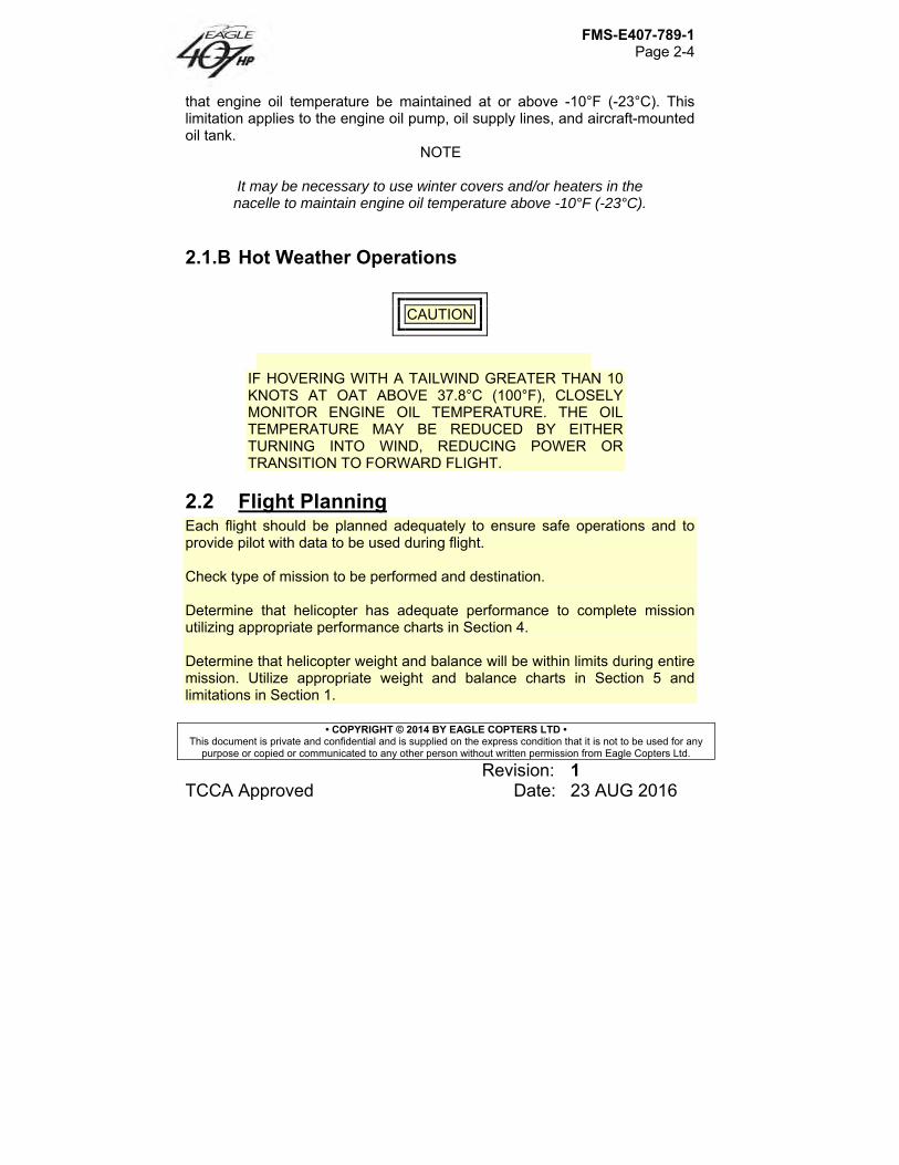
that engine oil temperature be maintained at or above -10°F (-23°C). This limitation applies to the engine oil pump, oil supply lines, and aircraft-mounted oil tank.
NOTE
It may be necessary to use winter covers and/or heaters in the nacelle to maintain engine oil temperature above -10°F (-23°C).
2.1.B Hot Weather Operations
CAUTION
IF HOVERING WITH A TAILWIND GREATER THAN 10 KNOTS AT OAT ABOVE 37.8°C (100°F), CLOSELY MONITOR ENGINE OIL TEMPERATURE. THE OIL TEMPERATURE MAY BE REDUCED BY EITHER TURNING INTO WIND, REDUCING POWER OR TRANSITION TO FORWARD FLIGHT.
2.2 Flight Planning Each flight should be planned adequately to ensure safe operations and to provide pilot with data to be used during flight. Check type of mission to be performed and destination. Determine that helicopter has adequate performance to complete mission utilizing appropriate performance charts in Section 4. Determine that helicopter weight and balance will be within limits during entire mission. Utilize appropriate weight and balance charts in Section 5 and limitations in Section 1.
FMS-E407-789-1 Page 2-5
• COPYRIGHT © 2014 BY EAGLE COPTERS LTD • This document is private and confidential and is supplied on the express condition that it is not to be used for any
purpose or copied or communicated to any other person without written permission from Eagle Copters Ltd.
Revision: 1 TCCA Approved Date: 23 AUG 2016
2.3 Preflight Check Pilot is responsible for determining whether helicopter is in condition for safe flight. Refer to Figure 2-1 for preflight check sequence.
NOTE Preflight check is not intended to be a detailed mechanical inspection but a guide to check condition of helicopter. This check may be made as comprehensive as conditions warrant at the discretion of pilot. All areas checked shall include a visual check for evidence of corrosion, particularly when helicopter is flown near or over salt water or in areas of high industrial emissions.
2.3.A Before Exterior Check 1. Flight planning – Completed. 2. Publications – Check. 3. GW and CG – Computed. 4. Helicopter servicing - Completed. 5. Battery – Connected.
2.3.B Exterior Check 2.3.B.1 FUSELAGE – CABIN RIGHT SIDE
FMS-E407-789-1 Page 2-6
• COPYRIGHT © 2014 BY EAGLE COPTERS LTD • This document is private and confidential and is supplied on the express condition that it is not to be used for any
purpose or copied or communicated to any other person without written permission from Eagle Copters Ltd.
Revision: 1 TCCA Approved Date: 23 AUG 2016
WARNING
FAILURE TO REMOVE ROTOR TIEDOWNS BEFORE ENGINE STARTING MAY RESULT IN SEVERE DAMAGE AND POSSIBLE INJURY.
1. All main rotor blades — Tiedowns removed, condition. 2. Right static port — Condition. 3. Cabin doors and hinge bolts — Condition and security. 4. Windows — Condition and security. 5. Landing gear — Condition. Ground handling wheel removed. 6. Forward and aft crosstube fairings (if installed) — Secured, condition, and aligned. 2.3.B.2 FUSELAGE – CENTER RIGHT SIDE 1. Engine inlet — Condition; remove inlet covers. 2. Cabin roof, transmission cowling, and engine air inlet area — Cleaned of all debris, accumulated snow and ice; cowling secured. 3. Forward fairing — Secured. 4. Transmission — Check oil level. Check oil level within OIL LEVEL markings 5. Transmission oil cooler lines — Condition and security. 6. Transmission mounts — Condition and security.
7. Main driveshaft — Condition.
FMS-E407-789-1 Page 2-7
• COPYRIGHT © 2014 BY EAGLE COPTERS LTD • This document is private and confidential and is supplied on the express condition that it is not to be used for any
purpose or copied or communicated to any other person without written permission from Eagle Copters Ltd.
Revision: 1 TCCA Approved Date: 23 AUG 2016
8. Access door — Secured. 9. Fuel filler cap — Visually check fuel level and cap secured.
NOTE
If helicopter is not parked on a level surface, fuel sump may not properly drain contaminants.
10. Fuel sump — Drain fuel sample as follows:
a. RIGHT and LEFT FUEL BOOST/ XFR circuit breaker switches — OFF.
b. BATT switch — BATT (on). c. EMERG. FUEL VALVE switch — OFF. d. FWD and AFT FUEL SUMP drain buttons — Press, drain sample,
then release. 11. Airframe fuel filter — Drain and check before first flight of day as follows:
a. RIGHT and LEFT FUEL BOOST/ XFR circuit breaker switches — LEFT and RIGHT (on).
b. EMERG. FUEL VALVE switch — ON. c. Fuel filter drain valve — Open, drain sample, then close.
12. Airframe Fuel filter test switch — Press and check A/F FUEL FILTER caution light illuminates. Release switch and check light extinguishes. 13. EMERG. FUEL VALVE switch — ON. 14. LEFT and RIGHT FUEL BOOST/XFR circuit breaker switches — OFF. 15. BATT switch — OFF. 16. Power plant area:
FMS-E407-789-1 Page 2-8
• COPYRIGHT © 2014 BY EAGLE COPTERS LTD • This document is private and confidential and is supplied on the express condition that it is not to be used for any
purpose or copied or communicated to any other person without written permission from Eagle Copters Ltd.
Revision: 1 TCCA Approved Date: 23 AUG 2016
a. Main driveshaft aft flexure — Condition. b. Engine and accessories — Condition, security of attachments,
evidence of oil leakage, cracks or damage. c. Engine mounts — Condition and security. d. Engine fuel pump — Security and condition, evidence of leakage. e. FMU — Security and condition, evidence of leakage. f. Combustion Housing and exhaust duct – Condition and security,
foreign matter, cracks, damage, dryness, hot spots, buckling. Remove covers and plugs.
g. Oil Filter Bypass Indicator – Check retracted h. Hoses and tubing — Chafing, security, condition, verify no leaks. i. Oil and Fuel drains – Clear. j. Wire harness – Chafing, security, condition. k. Power Turbine Rotor – Check for foreign matter and damage. l. Oil cooler blower inlet duct and screen — Clear obstructions,
condition and security.
17. Engine cowl — Secured. 18. Oil tank — Leaks, security, cap secured and correct quantity. 19. Access door — Secured. 20. Aft and upper fairing — Secured. 2.3.B.3 FUSELAGE – AFT RIGHT SIDE 1. Fuselage — Condition. 2. Tail rotor driveshaft cover — Condition and security. 3. Tailboom — Condition. 4. Horizontal stabilizer area:
a. Horizontal stabilizer — General condition and security of attachment.
FMS-E407-789-1 Page 2-9
• COPYRIGHT © 2014 BY EAGLE COPTERS LTD • This document is private and confidential and is supplied on the express condition that it is not to be used for any
purpose or copied or communicated to any other person without written permission from Eagle Copters Ltd.
Revision: 1 TCCA Approved Date: 23 AUG 2016
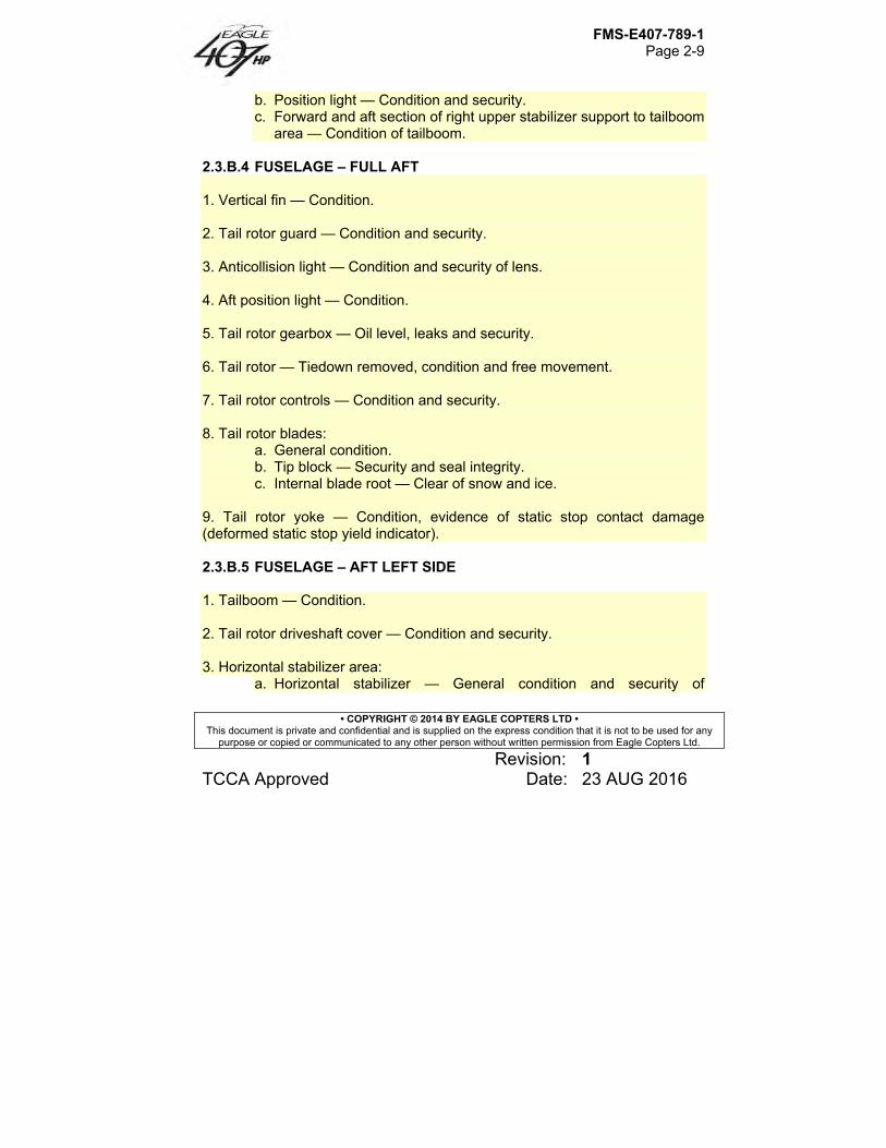
b. Position light — Condition and security. c. Forward and aft section of right upper stabilizer support to tailboom
area — Condition of tailboom. 2.3.B.4 FUSELAGE – FULL AFT 1. Vertical fin — Condition. 2. Tail rotor guard — Condition and security. 3. Anticollision light — Condition and security of lens. 4. Aft position light — Condition. 5. Tail rotor gearbox — Oil level, leaks and security. 6. Tail rotor — Tiedown removed, condition and free movement. 7. Tail rotor controls — Condition and security. 8. Tail rotor blades:
a. General condition. b. Tip block — Security and seal integrity. c. Internal blade root — Clear of snow and ice.
9. Tail rotor yoke — Condition, evidence of static stop contact damage (deformed static stop yield indicator). 2.3.B.5 FUSELAGE – AFT LEFT SIDE 1. Tailboom — Condition. 2. Tail rotor driveshaft cover — Condition and security. 3. Horizontal stabilizer area:
a. Horizontal stabilizer — General condition and security of
FMS-E407-789-1 Page 2-10
• COPYRIGHT © 2014 BY EAGLE COPTERS LTD • This document is private and confidential and is supplied on the express condition that it is not to be used for any
purpose or copied or communicated to any other person without written permission from Eagle Copters Ltd.
Revision: 1 TCCA Approved Date: 23 AUG 2016
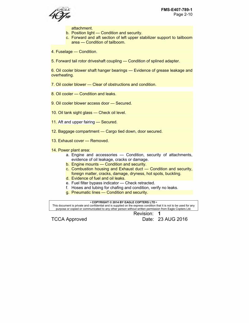
attachment. b. Position light — Condition and security. c. Forward and aft section of left upper stabilizer support to tailboom
area — Condition of tailboom.
4. Fuselage — Condition. 5. Forward tail rotor driveshaft coupling — Condition of splined adapter. 6. Oil cooler blower shaft hanger bearings — Evidence of grease leakage and overheating. 7. Oil cooler blower — Clear of obstructions and condition. 8. Oil cooler — Condition and leaks. 9. Oil cooler blower access door — Secured. 10. Oil tank sight glass — Check oil level. 11. Aft and upper fairing — Secured. 12. Baggage compartment — Cargo tied down, door secured. 13. Exhaust cover — Removed. 14. Power plant area:
a. Engine and accessories — Condition, security of attachments, evidence of oil leakage, cracks or damage.
b. Engine mounts — Condition and security. c. Combustion housing and Exhaust duct — Condition and security,
foreign matter, cracks, damage, dryness, hot spots, buckling. d. Evidence of fuel and oil leaks. e. Fuel filter bypass indicator — Check retracted. f. Hoses and tubing for chafing and condition, verify no leaks. g. Pneumatic lines — Condition and security.
FMS-E407-789-1 Page 2-11
• COPYRIGHT © 2014 BY EAGLE COPTERS LTD • This document is private and confidential and is supplied on the express condition that it is not to be used for any
purpose or copied or communicated to any other person without written permission from Eagle Copters Ltd.
Revision: 1 TCCA Approved Date: 23 AUG 2016
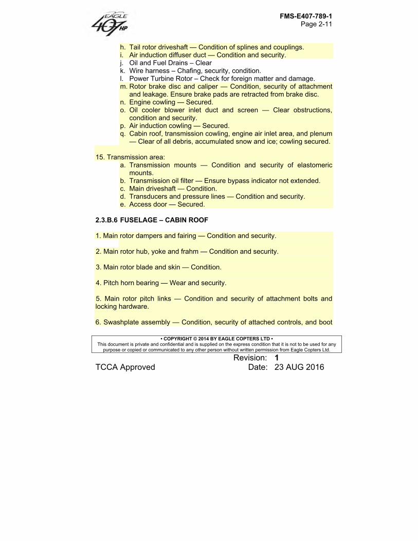
h. Tail rotor driveshaft — Condition of splines and couplings. i. Air induction diffuser duct — Condition and security. j. Oil and Fuel Drains – Clear k. Wire harness – Chafing, security, condition. l. Power Turbine Rotor – Check for foreign matter and damage. m. Rotor brake disc and caliper — Condition, security of attachment
and leakage. Ensure brake pads are retracted from brake disc. n. Engine cowling — Secured. o. Oil cooler blower inlet duct and screen — Clear obstructions,
condition and security. p. Air induction cowling — Secured. q. Cabin roof, transmission cowling, engine air inlet area, and plenum
— Clear of all debris, accumulated snow and ice; cowling secured. 15. Transmission area:
a. Transmission mounts — Condition and security of elastomeric mounts.
b. Transmission oil filter — Ensure bypass indicator not extended. c. Main driveshaft — Condition. d. Transducers and pressure lines — Condition and security. e. Access door — Secured.
2.3.B.6 FUSELAGE – CABIN ROOF
1. Main rotor dampers and fairing — Condition and security.
2. Main rotor hub, yoke and frahm — Condition and security. 3. Main rotor blade and skin — Condition. 4. Pitch horn bearing — Wear and security. 5. Main rotor pitch links — Condition and security of attachment bolts and locking hardware. 6. Swashplate assembly — Condition, security of attached controls, and boot
FMS-E407-789-1 Page 2-12
• COPYRIGHT © 2014 BY EAGLE COPTERS LTD • This document is private and confidential and is supplied on the express condition that it is not to be used for any
purpose or copied or communicated to any other person without written permission from Eagle Copters Ltd.
Revision: 1 TCCA Approved Date: 23 AUG 2016
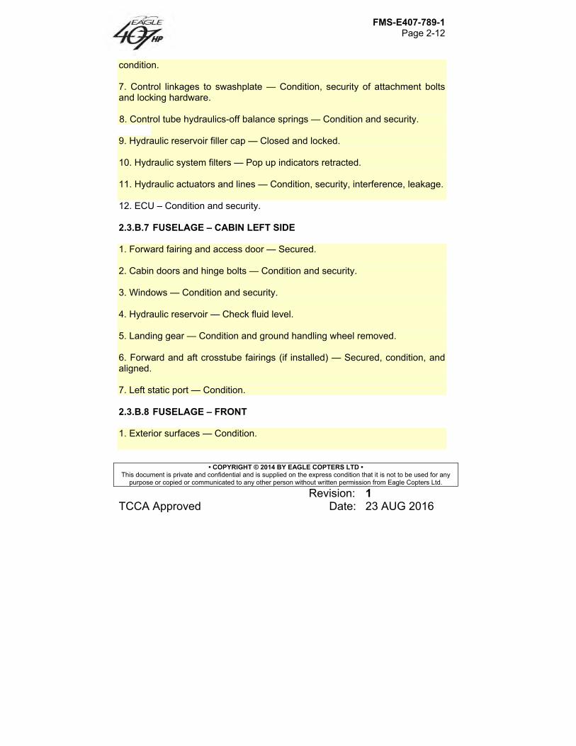
condition. 7. Control linkages to swashplate — Condition, security of attachment bolts and locking hardware. 8. Control tube hydraulics-off balance springs — Condition and security.
9. Hydraulic reservoir filler cap — Closed and locked. 10. Hydraulic system filters — Pop up indicators retracted. 11. Hydraulic actuators and lines — Condition, security, interference, leakage. 12. ECU – Condition and security. 2.3.B.7 FUSELAGE – CABIN LEFT SIDE
1. Forward fairing and access door — Secured. 2. Cabin doors and hinge bolts — Condition and security. 3. Windows — Condition and security. 4. Hydraulic reservoir — Check fluid level. 5. Landing gear — Condition and ground handling wheel removed. 6. Forward and aft crosstube fairings (if installed) — Secured, condition, and aligned. 7. Left static port — Condition. 2.3.B.8 FUSELAGE – FRONT 1. Exterior surfaces — Condition.
FMS-E407-789-1 Page 2-13
• COPYRIGHT © 2014 BY EAGLE COPTERS LTD • This document is private and confidential and is supplied on the express condition that it is not to be used for any
purpose or copied or communicated to any other person without written permission from Eagle Copters Ltd.
Revision: 1 TCCA Approved Date: 23 AUG 2016
2. Windshield — Condition and cleanliness. 3. Battery and vent lines — Condition and security. 4. HOUR METER circuit breaker — In. 5. Battery access door — Secured. 6. Pitot tube — Cover removed, clear of obstructions. 7. External power door — Condition and security. 8. Landing light lamps — Condition. 9. Antennas — Condition and security.
2.4 Interior and Prestart Check
1. Cabin interior — Clean, equipment secured. 2. Fire extinguisher — Installed and secured. 3. Cabin loading — Maintain CG within limits. 4. Passenger seat belts — Secured. 5. Copilot seat belt — Secured (if solo). 6. Doors — Secured. 7. Emergency Pedal Stop Release – Down and witness wired 8. Throttle — Closed. 9. LDG LTS switch — OFF.
FMS-E407-789-1 Page 2-14
• COPYRIGHT © 2014 BY EAGLE COPTERS LTD • This document is private and confidential and is supplied on the express condition that it is not to be used for any
purpose or copied or communicated to any other person without written permission from Eagle Copters Ltd.
Revision: 1 TCCA Approved Date: 23 AUG 2016
10. Communications switches — Set. 11. Emergency Fuel Valve - ON 12. Altimeter — Set. 13. Instruments — Correct indications. 14. Overhead switches — Set:
a. BATT switch — OFF. b. GEN switch — OFF. c. PART SEP switch (if installed) — OFF. d. ANTI COLL LT switch — ANTI COLL LT (on). e. HYD SYS switch — HYD SYS (on). f. CABIN LT/PASS switch — OFF. g. POS LT switch — As desired. h. DEFOG switch — OFF. i. PITOT HEATER switch — OFF. j. ENG ANTI ICE switch — OFF. k. AVIONICS MASTER switch — OFF. l. HEATER switch (if installed) — OFF. m. INSTR LT rheostat — OFF.
15. Overhead circuit breaker switches — OFF. 16. Overhead circuit breakers — In. 17. Rotor brake handle — Up and latched.
CAUTION
28 VDC EXTERNAL POWER SOURCE SHALL BE 500 AMPERES OR LESS TO REDUCE RISK OF STARTER DAMAGE FROM OVERHEATING.
FMS-E407-789-1 Page 2-15
• COPYRIGHT © 2014 BY EAGLE COPTERS LTD • This document is private and confidential and is supplied on the express condition that it is not to be used for any
purpose or copied or communicated to any other person without written permission from Eagle Copters Ltd.
Revision: 1 TCCA Approved Date: 23 AUG 2016
18. EXTERNAL POWER — Connected (if used). 19. BATT switch — ON for battery start, ON for GPU start, OFF for battery cart start. Observe the following:
a. Low rotor rpm, engine out and FADEC fail audio horn activated. b. MGT, Fuel Qty, Tq and Ng Indicators
Display 8.8.8.8. Display software version Display 0.0
c. MGT, Tq and Ng Indicators Display 0 – indicates no exceedance Display 0E – indicates an exceedance Display details of exceedance
d. MGT, Ng Indicators Display last flight cycle count for power turbine and gas
generator respectively.
NOTE
Np/Nr Fuel Pressure, Ammeter, Xmsn Oil Pressure and Engine Oil pressure and temperature needles move from park position to 0.0 or ambient.
NOTE
As part of the instrument self-test FADEC warning/caution lights/horn will cycle on and off.
NOTE
After instrument build-in test, no engine related caution/warning should be annunciated.
20. HORN MUTE button — Press to mute.
FMS-E407-789-1 Page 2-16
• COPYRIGHT © 2014 BY EAGLE COPTERS LTD • This document is private and confidential and is supplied on the express condition that it is not to be used for any
purpose or copied or communicated to any other person without written permission from Eagle Copters Ltd.
Revision: 1 TCCA Approved Date: 23 AUG 2016
21. Caution lights — ENG OUT, XMSN OIL PRESS, RPM, HYDRAULIC SYSTEM, GEN FAIL, L/FUEL BOOST, R/FUEL BOOST, L/FUEL XFR, R/FUEL XFR and ENG OIL PRESS will be illuminated.
NOTE
L/FUEL XFR and R/FUEL XFR will not be illuminated when forward fuel tank is empty.
22. PEDAL STOP PTT switch annunciator:
Pedals — Centered. Press — Verify PEDAL STOP caution and ENGAGED annunciator illuminated and left pedal travel restricted. Release — Verify PEDAL STOP caution and ENGAGED annunciator extinguished and both pedals travel unrestricted.
23. Flight controls — Loosen frictions; check travel and verify CYCLIC CENTERING light operation; position for start. Tighten friction as desired. 24. Throttle — Check freedom of travel and appropriate operation at OFF, IDLE, and FLY positions. Return throttle to OFF position.
NOTE
With INSTR LT rheostat on and CAUT LT switch positioned to DIM, caution lights are dimmed to a fixed intensity and cannot be adjusted by INSTR LT rheostat.
25. INSTR LT rheostat — As desired. 26. CAUT LT switch — As desired. 27. FUEL BOOST/XFR circuit breaker switches — LEFT (on) and RIGHT (on) and verify all boost and transfer caution lights extinguish.
FMS-E407-789-1 Page 2-17
• COPYRIGHT © 2014 BY EAGLE COPTERS LTD • This document is private and confidential and is supplied on the express condition that it is not to be used for any
purpose or copied or communicated to any other person without written permission from Eagle Copters Ltd.
Revision: 1 TCCA Approved Date: 23 AUG 2016
CAUTION
IT IS REQUIRED TO HAVE THE BOOST PUMPS ON FOR ALL PHASES OF FLIGHT.
28. FUEL pressure — Check. 29. CAUTION LT TEST button — Press to test. 30. LCD TEST button — Press to test, if desired. 31. FADEC FAIL TEST button — Press to test. 32. FIRE DETECT TEST button – Press to test. 33. CHIP DETECTOR TEST button – Press to test. 34. EMERG FUEL VALVE switch — ON, guard closed, FUEL VALVE light illuminates then extinguishes. 35. FUEL QTY — Check TOTAL and FWD tank quantity. 36. OAT/VOLTS display — Check OAT and select VOLTS.

FMS-E407-789-1 Page 2-18
• COPYRIGHT © 2014 BY EAGLE COPTERS LTD • This document is private and confidential and is supplied on the express condition that it is not to be used for any
purpose or copied or communicated to any other person without written permission from Eagle Copters Ltd.
Revision: 1 TCCA Approved Date: 23 AUG 2016
2.5 Engine Start
CAUTION
ANY ATTEMPT TO START ENGINE WHEN VOLTAGE IS BELOW 24 VOLTS MAY RESULT IN A HOT START. MONITOR FOR FADEC FAILURE. IF FADEC FAILS (FADEC FAIL WARNING LIGHT), ABORT START BY ROLLING THROTTLE TO OFF AND ENGAGE STARTER TO REDUCE MGT.
CAUTION
ABORT START IMMEDIATELY (SEE SECTION 3.3.L) IF ANY OF THE FOLLOWING EVENTS OCCURS: 1) Ng STOPS INCREASING PRIOR TO IDLE RPM. 2) ANY UNUSUAL NOISE OR VIBRATION OCCURS. 3) THE ECU FAILS. 4) THE ROTORCRAFT DC ELECTRICAL POWER
FAILS OR DROPS BELOW 18 VDC. The following normal start procedure is applicable for engine starts to IDLE or FLY. Ground idle is approximately 58 to 64 percent Ng. Starts accomplished with the engine throttle in the FLY position will result in engine acceleration up to the normal operating 100% Np/Nr.
FMS-E407-789-1 Page 2-19
• COPYRIGHT © 2014 BY EAGLE COPTERS LTD • This document is private and confidential and is supplied on the express condition that it is not to be used for any
purpose or copied or communicated to any other person without written permission from Eagle Copters Ltd.
Revision: 1 TCCA Approved Date: 23 AUG 2016
NOTE
ECU power-up testing will be terminated if the engine start sequence is initiated prior to the completion of BIT testing. If power-up testing is interrupted, FADEC warnings, cautions, and advisories will not be displayed.
NOTE
No cockpit indication of Ng is displayed until Ng is greater than 5 percent, and no cockpit indication of Np is displayed until Np is greater than 5 percent.
1. Collective — Minimum pitch 2. Rotorcraft electrical power — ON
NOTE
Allow 20 seconds for the ECU to complete its power-up testing prior to proceeding. Observe warnings, cautions, and advisories panel and verify that no engine indications are illuminated.
3. Anti-ice switch — OFF 4. Both Fuel pump switches — ON 5. Bleed air switch — OFF 6. Generator switch — OFF 7. Cyclic and pedals — Centered and CYCLIC CENTERING light extinguished.
FMS-E407-789-1 Page 2-20
• COPYRIGHT © 2014 BY EAGLE COPTERS LTD • This document is private and confidential and is supplied on the express condition that it is not to be used for any
purpose or copied or communicated to any other person without written permission from Eagle Copters Ltd.
Revision: 1 TCCA Approved Date: 23 AUG 2016
8. Throttle — IDLE or FLY 9. Warning, caution, advisory panel — NORMAL No warnings or cautions 10. Starter switch — Hold for > 0.5 seconds (Activate within 60 seconds of PLA movement.) 11. Warning, caution, advisory panel — START After this sequence has been completed, the engine ECU will provide automatic sequencing and control of the engine starter/ignition relay, providing electrical power to the starter during the engine starting cycle. Engine fuel flow is automatically regulated to control the Ng rate of acceleration and to maintain turbine temperature within limits. The engine should accelerate to IDLE or FLY, as selected, and stabilize within 1 minute. 12. Ng, Np, MGT, OP, and OT – NORMAL
NOTE
The ECU will automatically cut off fuel flow: (a) in the event of a failure that results in turbine
overtemperature during a start attempt, (b) if Ng does not reach 10 percent in 10 seconds, (c) if light-off does not occur within 35 seconds, or (d) if idle speeds are not achieved in 60 seconds.
NOTE
To reinitiate the start sequence, it will be necessary to terminate the start sequence by returning the engine PLA to OFF.
13. Warning, caution, advisory panel – NORMAL
FMS-E407-789-1 Page 2-21
• COPYRIGHT © 2014 BY EAGLE COPTERS LTD • This document is private and confidential and is supplied on the express condition that it is not to be used for any
purpose or copied or communicated to any other person without written permission from Eagle Copters Ltd.
Revision: 1 TCCA Approved Date: 23 AUG 2016
NOTE
Dispatching the aircraft with any FADEC system faults illuminated is not permitted, except as noted in ICA-E407-789 Chapter 76-00-00 paragraph 76.4.3.
14. Engine and transmission oil pressures — Check.
NOTE
If dual controls are installed, guard throttle to prevent inadvertent manipulation from co-pilot position.
15. BATT switch — ON (if applicable).
NOTE
Ensure BATT switch is positioned to ON prior to disconnecting external power source.
16. EXTERNAL POWER — Disconnect and close door (if applicable). 17. GEN switch — GEN (on); observe GEN FAIL light extinguishes.
NOTE
Turn generator OFF if ammeter indication drops to zero amps after an initial full scale indication. One reset is allowed. RESET generator and then turn generator back ON.
18. Voltmeter — 28.5 ±0.5 volts. 19. FADEC Reset – Test fluctuations on gauges

FMS-E407-789-1 Page 2-22
• COPYRIGHT © 2014 BY EAGLE COPTERS LTD • This document is private and confidential and is supplied on the express condition that it is not to be used for any
purpose or copied or communicated to any other person without written permission from Eagle Copters Ltd.
Revision: 1 TCCA Approved Date: 23 AUG 2016
20. FLIGHT INSTR circuit breaker switches (3) (if installed) — DG, ATT and TURN (on).
NOTE
If dual controls are installed, guard throttle to prevent inadvertent manipulation from co-pilot position.
2.5.A Dry Motoring Run – No Ignition
The following procedure is used for checks that require core engine rotation but do not require fuel flow. 1. Inlet and exhaust – Clear 2. Oil quantity – Adequate 3. Collective – Minimum pitch 4. Rotorcraft electrical power – ON
5. Ignition circuit breaker – Pulled 6. Starter switch – OFF 7. Throttle – OFF 8. Fuel pump switch – ON (for fuel pump lubrication) 9. Starter switch – START (switch held) 10. Ng and Np rpm – Indicating 11. Oil pressure – Positive indication

FMS-E407-789-1 Page 2-23
• COPYRIGHT © 2014 BY EAGLE COPTERS LTD • This document is private and confidential and is supplied on the express condition that it is not to be used for any
purpose or copied or communicated to any other person without written permission from Eagle Copters Ltd.
Revision: 1 TCCA Approved Date: 23 AUG 2016
NOTE
A 15- to 30-second cranking period is recommended for ventilating the engine immediately after a hot shutdown or a start abort due to overtemperature. Longer cranking is acceptable for ventilating the engine depending on starter duty cycle and available power. Additional ventilation motoring cycles spaced 2 to 3 minutes apart are recommended if not limited by starter duty cycle and available power.
12. Starter switch – OFF 13. Fuel Pump switch – OFF (after coast down)
2.5.B Wet Motoring Run – No Ignition The following procedure is used for checks requiring core engine rotation and fuel flow but no ignition. Failure to disconnect the fuel manifold before performing a wet motoring run may result in an over-temperature event or engine fire. 1. Inlet and exhaust – Clear 2. Oil quantity – Adequate 3. Collective – Minimum pitch 4. Rotorcraft electrical power – ON 5. Ignition circuit breaker – Pulled 6. Starter switch – OFF
FMS-E407-789-1 Page 2-24
• COPYRIGHT © 2014 BY EAGLE COPTERS LTD • This document is private and confidential and is supplied on the express condition that it is not to be used for any
purpose or copied or communicated to any other person without written permission from Eagle Copters Ltd.
Revision: 1 TCCA Approved Date: 23 AUG 2016
7. Throttle – IDLE 8. Both Fuel pump switches – ON 9. Starter switch – START (switch held) 10. Ng and Np rpm – Indicating 11. Oil pressure – Positive indication
12. Fuel Flow – Positive indication
The engine may be motored with fuel ON for 15 seconds. Observe starter limits.
13. Throttle – OFF
Check that fuel flow drops to zero, ensuring positive fuel shutoff.
Continue motoring for 1 minute to purge the engine of residual fuel. Observe starter duty cycle. 14. Starter switch – OFF
15. Both Fuel pump switches – OFF (after coast down)
2.6 Systems Check
2.6.A Preliminary Hydraulic Systems Check
NOTE
Uncommanded control movement or motoring with hydraulic system off may indicate hydraulic system
FMS-E407-789-1 Page 2-25
• COPYRIGHT © 2014 BY EAGLE COPTERS LTD • This document is private and confidential and is supplied on the express condition that it is not to be used for any
purpose or copied or communicated to any other person without written permission from Eagle Copters Ltd.
Revision: 1 TCCA Approved Date: 23 AUG 2016
malfunction. 1. HYD SYS switch — OFF. 2. HYDRAULIC SYSTEM caution light — Illuminated. 3. HYD SYS switch — HYD SYS (on). 4. HYDRAULIC SYSTEM caution light — Extinguished.
2.6.B Deleted
2.6.C Engine Run-Up 1. Throttle — Increase smoothly to FLY detent position while monitoring torque below 40%. Check RPM warning light extinguished at 95% NR. 2. NR and NP needles — Check matching and indicating 100%.
NOTE
Overhead circuit breakers highlighted with arrow graphic; are powered through AVIONICS MASTER switch.
3. AVIONICS MASTER switch — AVIONICS MASTER (on). 4. ELT (if installed) — Check for inadvertent transmission. 5. Flight controls — Check freedom with minimum friction. 6. ENG ANTI ICE switch — ENG ANTI ICE (on); check for MGT increase and illumination of ENGINE ANTI-ICE light.
FMS-E407-789-1 Page 2-26
• COPYRIGHT © 2014 BY EAGLE COPTERS LTD • This document is private and confidential and is supplied on the express condition that it is not to be used for any
purpose or copied or communicated to any other person without written permission from Eagle Copters Ltd.
Revision: 1 TCCA Approved Date: 23 AUG 2016
NOTE
If temperature is below 5°C (40°F) and visible moisture is present, ENG ANTI ICE shall be on.
7. ENG ANTI ICE switch — OFF; check MGT returns to normal and ENGINE ANTI-ICE light extinguishes; then ENG ANTI ICE (on) if required.
8. PITOT HEATER — Confirm operation (increase in ammeter load).
2.6.D Hydraulic Systems Check
NOTE
Hydraulic systems check is to determine proper operation of hydraulic actuators for each flight control system. If abnormal forces, unequal forces, control binding, or motoring are encountered, it may be an indication of a malfunctioning flight control actuator.
1. Collective — Full down. 2. NR — 100% RPM. 3. HYD SYS switch — OFF. 4. HYDRAULIC SYSTEM caution light — Illuminated. 5. Cyclic — Centered. 6. Cyclic control — Check normal operation by moving cyclic forward and aft, then left and right (approximately 1 inch). Center cyclic. 7. Collective — Check normal operation by increasing collective slightly (1 to 2 inches). Repeat two to three times as required. Return to full down position.
FMS-E407-789-1 Page 2-27
• COPYRIGHT © 2014 BY EAGLE COPTERS LTD • This document is private and confidential and is supplied on the express condition that it is not to be used for any
purpose or copied or communicated to any other person without written permission from Eagle Copters Ltd.
Revision: 1 TCCA Approved Date: 23 AUG 2016
8. Pedals — Check normal operation by displacing pedals slightly (1 inch). 9. HYD SYS switch — HYD SYS (on). 10. HYDRAULIC SYSTEM caution light — Extinguished. 11. Cyclic and collective friction — Set as desired.
2.7 Before Takeoff 1. ENG ANTI ICE switch — As required. 2. PITOT HEATER switch — As required. 3. Light switches — As required. 4. INSTR LT rheostat — As desired.
NOTE
For night flight, it is recommended to point the map light at the flight instruments and set to a low intensity. Sufficient night lighting will be provided in the event of an instrument lighting failure.
5. Radio(s) — Check as required. 6. Flight controls — Position and adjust frictions for takeoff.
CAUTION
FAILURE TO POSITION AND MAINTAIN THROTTLE IN
FMS-E407-789-1 Page 2-28
• COPYRIGHT © 2014 BY EAGLE COPTERS LTD • This document is private and confidential and is supplied on the express condition that it is not to be used for any
purpose or copied or communicated to any other person without written permission from Eagle Copters Ltd.
Revision: 1 TCCA Approved Date: 23 AUG 2016
FLY DETENT POSITION PRIOR TO TAKEOFF AND DURING NORMAL FLIGHT OPERATIONS CAN LIMIT AVAILABLE ENGINE POWER.
NOTE
The time required for moving collective from takeoff to the no-load position must be greater than 0.5 seconds. Collective movements of a shorter duration may result in Np overspeed.
NOTE
Dispatching the aircraft with any FADEC system faults is not permitted, except as noted in ICA-E407-789 Chapter 76-00-00 paragraph 76.4.3.
7. Throttle — Open to FLY detent position. Check 99 to 100% NR/NP. 8. Engine, transmission, and electrical instruments — Within limits. 9. Flight and navigation instruments — Check. 10. FUEL QTY — Note indication. 11. FUEL QTY FWD TANK button — Press, note fuel remaining in forward cell.
CAUTION
IN REARWARDS FLIGHT (OR WITH WIND UP THE TAIL) BETWEEN 135 deg AND 225 deg AZIMUTHS, THERE IS A POSSIBILITY OF GAS RE-INGESTION WHICH COULD RESULT IN A SUDDEN RISE IN MGT AND/OR NG.
FMS-E407-789-1 Page 2-29
• COPYRIGHT © 2014 BY EAGLE COPTERS LTD • This document is private and confidential and is supplied on the express condition that it is not to be used for any
purpose or copied or communicated to any other person without written permission from Eagle Copters Ltd.
Revision: 1 TCCA Approved Date: 23 AUG 2016
2.8 Takeoff 1. Rear facing seat headrests — Adjusted to proper position.
NOTE
During takeoffs disregard CYCLIC CENTERING light and position cyclic as required.
2. Collective — Increase to hover. 3. Directional control — As required to maintain desired heading. 4. Cyclic — Apply as required to accelerate smoothly. 5. Increase collective, up to 5% torque above hover power, to obtain desired rate of climb and airspeed. Once clear of the HV diagram shaded areas, adjust power and airspeed as desired. 6. PEDAL STOP PTT switch — Check ENGAGED annunciator illuminated above 55 ±5 KIAS.
2.9 In-Flight Operations 1. AIRSPEED — As desired (not to exceed VNE at flight altitude).
CAUTION
AT HIGH POWER AND HIGH AIRSPEED, CYCLIC ONLY ACCELERATIONS AND MANEUVERING MAY SIGNIFICANTLY INCREASE MGT AND TORQUE WITH
FMS-E407-789-1 Page 2-30
• COPYRIGHT © 2014 BY EAGLE COPTERS LTD • This document is private and confidential and is supplied on the express condition that it is not to be used for any
purpose or copied or communicated to any other person without written permission from Eagle Copters Ltd.
Revision: 1 TCCA Approved Date: 23 AUG 2016
NO COLLECTIVE INPUT. THIS INCREASE IS MORE RAPID AT LOWER OAT.
NOTE
Pilot shall keep feet on tail rotor pedals at all times. Do not press PEDAL STOP PTT switch in flight.
2. PEDAL STOP PTT switch — Check ENGAGED annunciator illuminated above 55 ±5 KIAS. 3. ENG ANTI ICE and PITOT HEATER switches — ENG ANTI ICE and PITOT HEATER switches on in visible moisture when ambient temperature is at or below 5°C (40°F). 4. Altimeter — Within limits. 5. FUEL QTY FWD TANK button — Press, note forward fuel tank indication.
NOTE
Full forward fuel tank quantity (approximately 256.0 pounds) will be indicated at approximately 770.0 pounds or greater total fuel. Fuel transfer will be complete at approximately 193.1 pounds total fuel.
2.10 Descent and Landing
NOTE
Large reductions in collective pitch at heavy GW may permit NR to increase independent of NP (needles split). Main rotor may be reengaged with a smooth increase in collective pitch.
FMS-E407-789-1 Page 2-31
• COPYRIGHT © 2014 BY EAGLE COPTERS LTD • This document is private and confidential and is supplied on the express condition that it is not to be used for any
purpose or copied or communicated to any other person without written permission from Eagle Copters Ltd.
Revision: 1 TCCA Approved Date: 23 AUG 2016
1. Rear facing seat headrests — Adjusted to proper position. 2. Flight controls — Adjust friction as desired. 3. Throttle — Fly detent position. Check 99 to 100% NP. 4. Flight path — As required for type of approach. 5. ENG ANTI ICE — As required. 6. LDG LTS switch — As desired.
NOTE
During run-on or slope landings, disregard CYCLIC CENTERING light and position cyclic as required. After landing is completed and collective is full down, reposition cyclic so that CYCLIC CENTERING light is extinguished.
7. PEDAL STOP PTT switch — Check ENGAGED annunciator extinguished below 50 ±5 KIAS.
2.11 Engine Shutdown 1. Collective — Full down. 2. Cyclic and pedals — Centered and CYCLIC CENTERING light extinguished. 3. Cyclic friction — Increase so that cyclic maintains centered position. 4. LDG LTS switch — OFF. 5. Throttle — IDLE. Check RPM warning light illuminated and audio on at
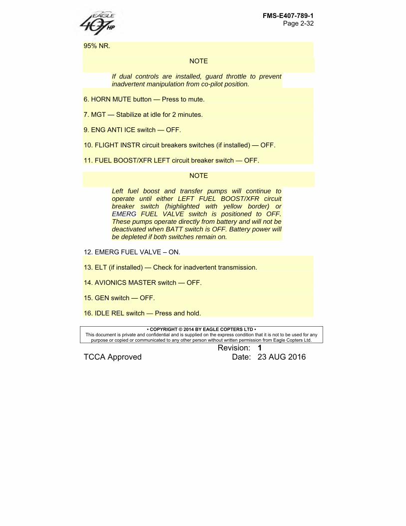
FMS-E407-789-1 Page 2-32
• COPYRIGHT © 2014 BY EAGLE COPTERS LTD • This document is private and confidential and is supplied on the express condition that it is not to be used for any
purpose or copied or communicated to any other person without written permission from Eagle Copters Ltd.
Revision: 1 TCCA Approved Date: 23 AUG 2016
95% NR.
NOTE
If dual controls are installed, guard throttle to prevent inadvertent manipulation from co-pilot position.
6. HORN MUTE button — Press to mute. 7. MGT — Stabilize at idle for 2 minutes. 9. ENG ANTI ICE switch — OFF. 10. FLIGHT INSTR circuit breakers switches (if installed) — OFF. 11. FUEL BOOST/XFR LEFT circuit breaker switch — OFF.
NOTE
Left fuel boost and transfer pumps will continue to operate until either LEFT FUEL BOOST/XFR circuit breaker switch (highlighted with yellow border) or EMERG FUEL VALVE switch is positioned to OFF. These pumps operate directly from battery and will not be deactivated when BATT switch is OFF. Battery power will be depleted if both switches remain on.
12. EMERG FUEL VALVE – ON. 13. ELT (if installed) — Check for inadvertent transmission. 14. AVIONICS MASTER switch — OFF. 15. GEN switch — OFF. 16. IDLE REL switch — Press and hold.
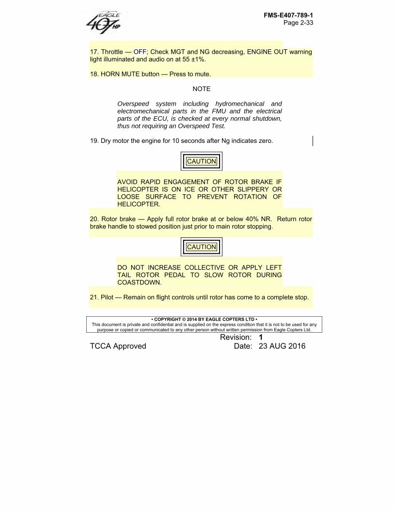
FMS-E407-789-1 Page 2-33
• COPYRIGHT © 2014 BY EAGLE COPTERS LTD • This document is private and confidential and is supplied on the express condition that it is not to be used for any
purpose or copied or communicated to any other person without written permission from Eagle Copters Ltd.
Revision: 1 TCCA Approved Date: 23 AUG 2016
17. Throttle — OFF; Check MGT and NG decreasing, ENGINE OUT warning light illuminated and audio on at 55 ±1%. 18. HORN MUTE button — Press to mute.
NOTE
Overspeed system including hydromechanical and electromechanical parts in the FMU and the electrical parts of the ECU, is checked at every normal shutdown, thus not requiring an Overspeed Test.
19. Dry motor the engine for 10 seconds after Ng indicates zero.
CAUTION
AVOID RAPID ENGAGEMENT OF ROTOR BRAKE IF HELICOPTER IS ON ICE OR OTHER SLIPPERY OR LOOSE SURFACE TO PREVENT ROTATION OF HELICOPTER.
20. Rotor brake — Apply full rotor brake at or below 40% NR. Return rotor brake handle to stowed position just prior to main rotor stopping.
CAUTION
DO NOT INCREASE COLLECTIVE OR APPLY LEFT TAIL ROTOR PEDAL TO SLOW ROTOR DURING COASTDOWN.
21. Pilot — Remain on flight controls until rotor has come to a complete stop.
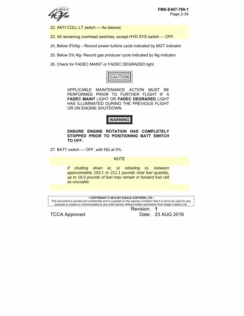
FMS-E407-789-1 Page 2-34
• COPYRIGHT © 2014 BY EAGLE COPTERS LTD • This document is private and confidential and is supplied on the express condition that it is not to be used for any
purpose or copied or communicated to any other person without written permission from Eagle Copters Ltd.
Revision: 1 TCCA Approved Date: 23 AUG 2016
22. ANTI COLL LT switch — As desired. 23. All remaining overhead switches, except HYD SYS switch — OFF. 24. Below 5%Ng – Record power turbine cycle indicated by MGT indicator 25. Below 5% Ng- Record gas producer cycle indicated by Ng indicator. 26. Check for FADEC MAINT or FADEC DEGRADED light.
CAUTION
APPLICABLE MAINTENANCE ACTION MUST BE PERFORMED PRIOR TO FURTHER FLIGHT IF A FADEC MAINT LIGHT OR FADEC DEGRADED LIGHT HAS ILLUMINATED DURING THE PREVIOUS FLIGHT OR ON ENGINE SHUTDOWN.
WARNING
ENSURE ENGINE ROTATION HAS COMPLETELY STOPPED PRIOR TO POSITIONING BATT SWITCH TO OFF.
27. BATT switch — OFF, with NG at 0%.
NOTE
If shutting down at, or refueling to, between approximately 193.1 to 211.1 pounds total fuel quantity, up to 18.0 pounds of fuel may remain in forward fuel cell as unusable.
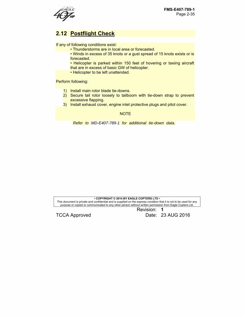
FMS-E407-789-1 Page 2-35
• COPYRIGHT © 2014 BY EAGLE COPTERS LTD • This document is private and confidential and is supplied on the express condition that it is not to be used for any
purpose or copied or communicated to any other person without written permission from Eagle Copters Ltd.
Revision: 1 TCCA Approved Date: 23 AUG 2016
2.12 Postflight Check If any of following conditions exist:
• Thunderstorms are in local area or forecasted. • Winds in excess of 35 knots or a gust spread of 15 knots exists or is forecasted. • Helicopter is parked within 150 feet of hovering or taxiing aircraft that are in excess of basic GW of helicopter. • Helicopter to be left unattended.
Perform following:
1) Install main rotor blade tie-downs. 2) Secure tail rotor loosely to tailboom with tie-down strap to prevent
excessive flapping. 3) Install exhaust cover, engine inlet protective plugs and pitot cover.
NOTE
Refer to MD-E407-789-1 for additional tie-down data.
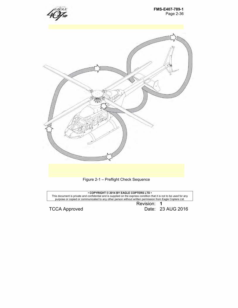
FMS-E407-789-1 Page 2-36
• COPYRIGHT © 2014 BY EAGLE COPTERS LTD • This document is private and confidential and is supplied on the express condition that it is not to be used for any
purpose or copied or communicated to any other person without written permission from Eagle Copters Ltd.
Revision: 1 TCCA Approved Date: 23 AUG 2016
Figure 2-1 – Preflight Check Sequence
FMS-E407-789-1 Page 3-1
• COPYRIGHT © 2014 BY EAGLE COPTERS LTD • This document is private and confidential and is supplied on the express condition that it is not to be used for any
purpose or copied or communicated to any other person without written permission from Eagle Copters Ltd.
Revision: 2 TCCA Approved Date: 23 JAN 2018
Section 3 Emergency/Malfunction Procedures
Table of Contents
3.1 Introduction .......................................................................................... 3 3.2 Definitions ............................................................................................ 3 3.3 Engine .................................................................................................. 4 3.3.A Engine Failure ................................................................................. 4
3.3.A.1 Engine Failure – Hovering ........................................................... 4 3.3.A.2 Engine Failure – In Flight ............................................................. 5
3.3.B Engine Restart In Flight ................................................................... 6 3.3.C Engine Underspeed ......................................................................... 8 3.3.D Engine Overspeed ........................................................................... 8 3.3.E Engine Compressor Stall ................................................................. 9 3.3.F Engine Hot Start/Shutdown ........................................................... 10 3.3.G Engine Oil Pressure Low, High or Fluctuating .............................. 10 3.3.H Engine Oil Temperature High ........................................................ 11 3.3.J Driveshaft Failure .......................................................................... 11 3.3.K FADEC Failures ............................................................................ 13
3.3.K.1 FADEC CH FAIL (Single Ch FADEC Failure) ........................... 13 3.3.K.2 FADEC FAIL (Dual Ch FADEC Failure) .................................... 13 3.3.K.3 FADEC DEGRADED (In Flight) ................................................. 14 3.3.K.4 FADEC MAINT (In Flight) .......................................................... 15
3.3.L Emergency Shutdown ................................................................... 15 3.4 Fire ..................................................................................................... 15 3.4.A Engine Fire On Ground ................................................................. 15 3.4.B Engine Fire During Flight ............................................................... 16 3.4.C Cabin Smoke or Fumes ................................................................. 17 3.4.D Electrical Fire ................................................................................. 17 3.5 Tail Rotor ........................................................................................... 19 3.5.A Complete Loss of Tail Rotor Thrust .............................................. 19
3.5.A.1 Hovering..................................................................................... 19 3.5.A.2 In Flight ...................................................................................... 20
3.5.B Fixed Pitch Failures ....................................................................... 20
FMS-E407-789-1 Page 3-2
• COPYRIGHT © 2014 BY EAGLE COPTERS LTD • This document is private and confidential and is supplied on the express condition that it is not to be used for any
purpose or copied or communicated to any other person without written permission from Eagle Copters Ltd.
Revision: 2 TCCA Approved Date: 23 JAN 2018
3.5.B.1 Hovering .................................................................................... 21 3.5.B.2 In Flight – Left Pedal Applied .................................................... 21 3.5.B.3 In Flight – Right Pedal Applied .................................................. 22
3.6 Hydraulic System .............................................................................. 22 3.6.A Loss of Hydraulic Pressure ........................................................... 22 3.6.B Flight Control Actuator Malfunction ............................................... 22 3.7 Electrical System ............................................................................... 23 3.7.A Generator Failure .......................................................................... 23 3.7.B Excessive Electrical Load ............................................................. 24 3.8 Fuel System ...................................................................................... 25 3.8.A Dual Fuel Transfer Failure ............................................................ 25 3.9 Cyclic Cam Jam ................................................................................ 26 3.10 Warning, Caution and Advisory Lights/Messages ............................ 26
List of Tables
Table 3-1: Warning (Red) Lights ................................................................... 27 Table 3-2: Caution (Amber) and Advisory (White/Green) Lights .................. 30
FMS-E407-789-1 Page 3-3
• COPYRIGHT © 2014 BY EAGLE COPTERS LTD • This document is private and confidential and is supplied on the express condition that it is not to be used for any
purpose or copied or communicated to any other person without written permission from Eagle Copters Ltd.
Revision: 2 TCCA Approved Date: 23 JAN 2018
Section 3 Emergency/Malfunction Procedures
3.1 Introduction Following procedures contain indications of failures or malfunctions which affect safety of crew, helicopter, ground personnel or property; use of emergency features of primary and backup systems; and appropriate warnings, cautions, and explanatory notes. Tables 3-1 and 3-2 list fault conditions and corrective actions for warning lights and caution/advisory lights respectively.
NOTE
All corrective action procedures listed herein assume pilot gives first priority to helicopter control and a safe flight path. A tripped circuit breaker should not be reset in flight unless deemed necessary for safe completion of the flight. If a tripped circuit breaker is deemed necessary for safe completion of the flight, it should only be reset one time.
Helicopter should not be operated following any precautionary landing until cause of malfunction has been determined and corrective maintenance action taken.
3.2 Definitions Following terms indicate degree of urgency in landing helicopter. LAND AS SOON Land without delay at nearest suitable area AS POSSIBLE (i.e., open field) at which a safe approach and
landing is reasonably assured.
FMS-E407-789-1 Page 3-4
• COPYRIGHT © 2014 BY EAGLE COPTERS LTD • This document is private and confidential and is supplied on the express condition that it is not to be used for any
purpose or copied or communicated to any other person without written permission from Eagle Copters Ltd.
Revision: 2 TCCA Approved Date: 23 JAN 2018
LAND AS SOON Landing site and duration of flight are at AS PRACTICAL discretion of pilot. Extended flight beyond
nearest approved landing area is not recommended.
Following terms are used to describe operating condition of a system, subsystem, assembly, or component. Affected Fails to operate in intended or usual
manner. Normal Operates in intended or usual manner.
3.3 Engine
3.3.A Engine Failure
3.3.A.1 Engine Failure – Hovering Indications:
1. Left Yaw 2. ENGINE OUT and RPM warning lights illuminated 3. Engine instruments indicate power loss. 4. Engine out audio activated when NG drops below 55%. 5. NR decreasing with RPM warning light and audio on when NR drops
below 95%. Procedure:
1. Maintain heading and attitude control. 2. Collective – Adjust to control NR and rate of descent.
Increase prior to ground contact to cushion landing.
FMS-E407-789-1 Page 3-5
• COPYRIGHT © 2014 BY EAGLE COPTERS LTD • This document is private and confidential and is supplied on the express condition that it is not to be used for any
purpose or copied or communicated to any other person without written permission from Eagle Copters Ltd.
Revision: 2 TCCA Approved Date: 23 JAN 2018
NOTE
Amplitude of collective movement is a function of height above ground. Any forward airspeed will aid in ability to cushion landing.
3. Deleted 4. Complete helicopter shut down.
3.3.A.2 Engine Failure – In Flight Indications:
1. Left yaw. 2. ENGINE OUT and RPM warning lights illuminated. 3. Engine instruments indicate power loss. 4. Engine out audio activated when NG drops below 55%. 5. NR decreasing with RPM warning light and audio on when NR drops
below 95%.
Procedure: 1. Maintain heading and attitude control. 2. Collective – Adjust as required to maintain 85 to 107% NR.
NOTE
Maintaining NR at high end of operating range will provide maximum rotor energy to accomplish landing, but will cause an increased rate of descent.
3. Cyclic – Adjust to obtain desired autorotative AIRSPEED.
FMS-E407-789-1 Page 3-6
• COPYRIGHT © 2014 BY EAGLE COPTERS LTD • This document is private and confidential and is supplied on the express condition that it is not to be used for any
purpose or copied or communicated to any other person without written permission from Eagle Copters Ltd.
Revision: 2 TCCA Approved Date: 23 JAN 2018
NOTE
Maximum AIRSPEED for steady state autorotation is 100 KIAS. Minimum rate of descent airspeed is 55 KIAS. Maximum glide distance airspeed is 80 KIAS.
4. Attempt engine restart if ample altitude remains. (Refer to ENGINE
RESTART, paragraph 3.3.B).
If engine restart is not attempted or not successful: 5. EMER. FUEL VALVE switch – OFF. 6. At low altitude:
a. Throttle – closed. b. Flare to lose airspeed
7. Apply collective as flare effect decreases to further reduce forward speed and cushion landing. Upon ground contact, collective shall be reduced smoothly while maintaining cyclic in neutral or centered position.
8. Complete helicopter shutdown.
3.3.B Engine Restart In Flight An engine restart may be attempted in flight if time and altitude permit.
CAUTION
TO INITIATE AN IN-FLIGHT RESTART, Ng MUST BE LESS THAN 10 PERCENT AND THROTTLE MUST BE CYCLED THROUGH THE OFF POSITION.
FMS-E407-789-1 Page 3-7
• COPYRIGHT © 2014 BY EAGLE COPTERS LTD • This document is private and confidential and is supplied on the express condition that it is not to be used for any
purpose or copied or communicated to any other person without written permission from Eagle Copters Ltd.
Revision: 2 TCCA Approved Date: 23 JAN 2018
CAUTION
ABORT START IMMEDIATELY IF ANY OF THE FOLLOWING EVENTS OCCURS: 1) Ng STOPS INCREASING PRIOR TO IDLE RPM. 2) ANY UNUSUAL NOISE OR VIBRATION OCCURS. 3) THE FADEC FAIL WARNING LIGHT ILLUMINATES. 4) THE ROTORCRAFT DC ELECTRICAL POWER
FAILS OR DROPS BELOW 18 VDC.
CAUTION
IF CAUSE OF FAILURE IS OBVIOUSLY MECHANICAL, AS EVIDENCED BY ABNORMAL METALLIC OR GRINDING SOUNDS, DO NOT ATTEMPT A RESTART.
Procedure:
1. Anti-ice switch – OFF 2. Generator switch – OFF 3. Ng – Less than 10 percent 4. EMERG. FUEL VALVE – ON 5. Throttle – IDLE (Cycle through OFF first.) 6. Starter switch – Hold for > 0.5 second 7. START advisory light – ILLUMINATED 8. Throttle – Advance smoothly to FLY detent position
If restart is unsuccessful, abort start and secure engine as follows:
9. Throttle – OFF 10. EMERG. FUEL VALVE switch – OFF. 11. Accomplish autorotative descent and landing.
FMS-E407-789-1 Page 3-8
• COPYRIGHT © 2014 BY EAGLE COPTERS LTD • This document is private and confidential and is supplied on the express condition that it is not to be used for any
purpose or copied or communicated to any other person without written permission from Eagle Copters Ltd.
Revision: 2 TCCA Approved Date: 23 JAN 2018
3.3.C Engine Underspeed No Caution/Warning/Advisory lights illuminated Indications:
1. Decrease in NG 2. Subsequent decrease in NP 3. Possible decrease in NR 4. Decrease in TRQ
Procedure:
1. Collective – Adjust as required to maintain 85 to 107% NR 2. Throttle – Confirm in FLY detent position 3. NR – Maintain 95 to 100% with collective 4. Land as soon as practical
3.3.D Engine Overspeed Indications:
1. ENGINE OVSPD warning annunciator is on. 2. Increase in NR. 3. Increase in NP. 4. Increase in NG. 5. Increase in TRQ.
Procedure:
1. Adjust throttle and collective as necessary 2. Monitor gauges. 3. Land as soon as possible.
CAUTION
IF UNABLE TO MAINTAIN NR, NP, NG OR MGT, PREPARE FOR A POWER OFF LANDING BY
FMS-E407-789-1 Page 3-9
• COPYRIGHT © 2014 BY EAGLE COPTERS LTD • This document is private and confidential and is supplied on the express condition that it is not to be used for any
purpose or copied or communicated to any other person without written permission from Eagle Copters Ltd.
Revision: 2 TCCA Approved Date: 23 JAN 2018
LOWERING COLLECTIVE AND SHUTTING DOWN ENGINE.
3.3.E Engine Compressor Stall Indications:
1. Engine pops 2. High or erratic MGT 3. Decreasing or erratic NG or NP 4. TRQ oscillations
Procedure:
1. Collective – Reduce power, maintain slow cruise flight 2. MGT and NG – Check for normal indications 3. ENG ANTI ICE switch – ON 4. PART SEP switch (if installed) – ON 5. HEATER switch (if installed) – ON
NOTE
Severity of compressor stalls will dictate if engine should be shut down and treated as an engine failure. Violent stalls can cause damage to engine and drive system components, and must be handled as an emergency condition. Stalls of a less severe nature (one or two low intensity pops) may permit continued operation of engine at a reduced power level, avoiding condition that result in compressor stall.
If pilot elects to continue flight: 6. Collective – Increase slowly to achieve desired power level. 7. MGT and NG – Monitor for normal response. 8. Land as soon as practical.
FMS-E407-789-1 Page 3-10
• COPYRIGHT © 2014 BY EAGLE COPTERS LTD • This document is private and confidential and is supplied on the express condition that it is not to be used for any
purpose or copied or communicated to any other person without written permission from Eagle Copters Ltd.
Revision: 2 TCCA Approved Date: 23 JAN 2018
If pilot elects to shut down engine: 9. Enter autorotation 10. Throttle – OFF 11. EMERG. FUEL VALVE switch – OFF 12. Collective – Adjust as required to maintain 85 to 107% NR 13. Cyclic – Adjust as required to maintain desired airspeed 14. Prepare for power-off landing
3.3.F Engine Hot Start/Shutdown Indications:
1. Excessive MGT 2. Visible smoke or fire
Procedure:
1. Throttle – OFF 2. EMERG. FUEL VALVE switch – OFF 3. STARTER switch – Ensure starter is motoring engine until
MGT stabilizes at normal temperature. 4. Shut helicopter down.
3.3.G Engine Oil Pressure Low, High or Fluctuating Indications:
1. Engine oil pressure below minimum. 2. Engine oil pressure above maximum or fluctuating abnormally. 3. CHECK INSTR caution annunciator is on. 4. ENG OIL PRESS caution annunciator illuminated
Procedure:
1. Engine oil pressure below minimum: a. Monitor engine oil pressure and temperature. b. Land as soon as possible.
2. Engine oil pressure above maximum or fluctuating abnormally. a. Operate at the lowest practical power setting.
FMS-E407-789-1 Page 3-11
• COPYRIGHT © 2014 BY EAGLE COPTERS LTD • This document is private and confidential and is supplied on the express condition that it is not to be used for any
purpose or copied or communicated to any other person without written permission from Eagle Copters Ltd.
Revision: 2 TCCA Approved Date: 23 JAN 2018
b. Monitor engine oil pressure and temperature. c. Land as soon as practical.
3.3.H Engine Oil Temperature High Indications:
1. Engine oil temperature increasing above normal. 2. Engine oil temperature above maximum. 3. CHECK INSTR caution annunciator is on.
Procedure:
1. Reduce to the lowest practical power setting. 2. If temperature remains above the maximum limit even after reducing
power, land as soon as possible. 3. If the temperature normalizes, monitor gauge and land as soon as
practical.
3.3.J Driveshaft Failure
WARNING
FAILURE OF MAIN DRIVESHAFT TO TRANSMISSION WILL RESULT IN COMPLETE LOSS OF POWER TO THE MAIN ROTOR. ALTHOUGH COCKPIT INDICATIONS FOR A DRIVESHAFT FAILURE ARE SIMILAR TO AN ENGINE OVERSPEED, IT IS IMPERATIVE THAT AUTOROTATIVE FLIGHT PROCEDURES BE ESTABLISHED IMMEDIATELY. FAILURE TO REACT IMMEDIATELY TO ROTOR RPM AUDIO, RPM LIGHT AND NP/NR TACHOMETER INDICATIONS CAN RESULT IN LOSS OF CONTROL.
Indications:
1. Left yaw
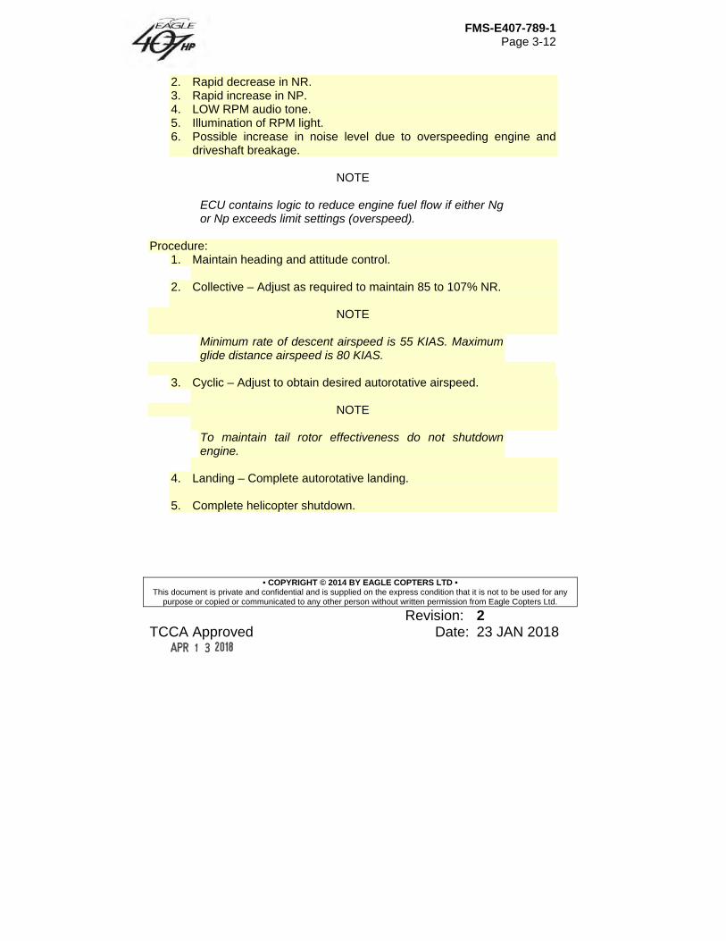
FMS-E407-789-1 Page 3-12
• COPYRIGHT © 2014 BY EAGLE COPTERS LTD • This document is private and confidential and is supplied on the express condition that it is not to be used for any
purpose or copied or communicated to any other person without written permission from Eagle Copters Ltd.
Revision: 2 TCCA Approved Date: 23 JAN 2018
2. Rapid decrease in NR. 3. Rapid increase in NP. 4. LOW RPM audio tone. 5. Illumination of RPM light. 6. Possible increase in noise level due to overspeeding engine and
driveshaft breakage.
NOTE
ECU contains logic to reduce engine fuel flow if either Ng or Np exceeds limit settings (overspeed).
Procedure:
1. Maintain heading and attitude control.
2. Collective – Adjust as required to maintain 85 to 107% NR.
NOTE
Minimum rate of descent airspeed is 55 KIAS. Maximum glide distance airspeed is 80 KIAS.
3. Cyclic – Adjust to obtain desired autorotative airspeed.
NOTE
To maintain tail rotor effectiveness do not shutdown engine.
4. Landing – Complete autorotative landing. 5. Complete helicopter shutdown.
FMS-E407-789-1 Page 3-13
• COPYRIGHT © 2014 BY EAGLE COPTERS LTD • This document is private and confidential and is supplied on the express condition that it is not to be used for any
purpose or copied or communicated to any other person without written permission from Eagle Copters Ltd.
Revision: 2 TCCA Approved Date: 23 JAN 2018
3.3.K FADEC Failures
3.3.K.1 FADEC CH FAIL (Single Ch FADEC Failure) Indications:
1. FADEC CH FAIL warning light is on. 2. FADEC DEGRADED warning light may illuminate.
Procedure:
1. Press and release FADEC RESET switch.
NOTE
During FADEC RESET, engine instruments may fluctuate.
2. If the FADEC CH FAIL caution clears, continue the flight. 3. If the FADEC CH FAIL reappears, stabilize the rotorcraft,
avoid abrupt control inputs, and land as soon as practical.
3.3.K.2 FADEC FAIL (Dual Ch FADEC Failure)
Indications: 1. FADEC FAIL audio activated. 2. FADEC FAIL warning light illuminated. 3. FADEC CH FAIL warning light illuminated 4. Fuel flow fixed at its last commanded value.
Procedure:
1. Maintain collective position. 2. Press and release FADEC RESET switch.
FMS-E407-789-1 Page 3-14
• COPYRIGHT © 2014 BY EAGLE COPTERS LTD • This document is private and confidential and is supplied on the express condition that it is not to be used for any
purpose or copied or communicated to any other person without written permission from Eagle Copters Ltd.
Revision: 2 TCCA Approved Date: 23 JAN 2018
NOTE
During FADEC RESET, engine instruments may fluctuate.
3. If FADEC FAIL warning light extinguishes, land as soon as possible. 4. If FADEC FAIL warning light remains illuminated, then depending on
power setting, pilot may choose to perform a run-on landing or an auto-rotation.
WARNING
THE THROTTLE WILL BE INOPERATIVE. USE EMERG. FUEL VALVE SWITCH TO SHUT OFF FUEL.
3.3.K.3 FADEC DEGRADED (In Flight) Indications:
1. FADEC DEGRADED warning light is on. 2. Engine response may be reduced.
Procedure:
1. Stabilize the rotorcraft and avoid abrupt control inputs to minimize possible Np/Nr variations.
2. Press and release FADEC RESET switch.
NOTE
During FADEC RESET, engine instruments may fluctuate.
3. If the FADEC DEGRADED caution clears, continue the flight. 4. If the FADEC DEGRADED reappears, stabilize the rotorcraft,
avoid abrupt control inputs, and land as soon as practical.
FMS-E407-789-1 Page 3-15
• COPYRIGHT © 2014 BY EAGLE COPTERS LTD • This document is private and confidential and is supplied on the express condition that it is not to be used for any
purpose or copied or communicated to any other person without written permission from Eagle Copters Ltd.
Revision: 2 TCCA Approved Date: 23 JAN 2018
3.3.K.4 FADEC MAINT (In Flight) Indications:
1. FADEC MAINT warning light is on.
NOTE
A FADEC MAINT light in flight is an indication of a frangible fuse fault
Procedure:
1. Stabilize the rotorcraft and avoid abrupt control inputs to minimize possible Np/Nr variations.
2. Land as soon as practical.
3.3.L Emergency Shutdown Procedure:
1. Throttle – OFF. 2. EMERG. FUEL VALVE switch – OFF. 3. Generator Switch – OFF. 4. Fuel BOOST/XFR – OFF. 5. Complete helicopter shutdown.
3.4 Fire
3.4.A Engine Fire On Ground Indications:
1. Smoke. 2. Fumes. 3. Fire. 4. ENGINE FIRE warning annunciator illuminated.
FMS-E407-789-1 Page 3-16
• COPYRIGHT © 2014 BY EAGLE COPTERS LTD • This document is private and confidential and is supplied on the express condition that it is not to be used for any
purpose or copied or communicated to any other person without written permission from Eagle Copters Ltd.
Revision: 2 TCCA Approved Date: 23 JAN 2018
Procedure: 1. Throttle – OFF 2. EMERG. FUEL VALVE – OFF 3. Fuel BOOST/XFR – OFF 4. GEN Switch – OFF 5. BATT Switch – OFF 6. Rotor brake – Engage 7. Exit helicopter.
3.4.B Engine Fire During Flight Indications:
1. Smoke. 2. Fumes. 3. Fire. 4. ENGINE FIRE warning annunciator illuminated.
Procedure:
1. In-flight – Immediately enter autorotation. 2. Throttle – OFF 3. EMERG. FUEL VALVE – OFF 4. Fuel BOOST/XFR – OFF 5. Execute autorotative descent and landing. 6. BATT switch – OFF.
NOTE
Do not restart engine until corrective maintenance has been performed.
FMS-E407-789-1 Page 3-17
• COPYRIGHT © 2014 BY EAGLE COPTERS LTD • This document is private and confidential and is supplied on the express condition that it is not to be used for any
purpose or copied or communicated to any other person without written permission from Eagle Copters Ltd.
Revision: 2 TCCA Approved Date: 23 JAN 2018
3.4.C Cabin Smoke or Fumes Indications:
1. Smoke. 2. Fumes.
Procedure:
1. In-flight – Start descent. 2. AIR COND BLO switch (if installed) – OFF. 3. HEATER switch (if installed) – OFF. 4. All vents – Open. 5. Side windows – Open.
If time and altitude permits:
6. Source – Attempt to identify and secure. 7. If source is identified and smoke and/or fumes still persist – Land as
soon as possible. 8. If source is identified and smoke and/or fumes are cleared – Land as
soon as practical.
3.4.D Electrical Fire Indications:
1. Smoke fumes or fire. 2. Possible indication of abnormal amps.
Procedure:
1. Vents/side windows – Open, as required; ventilate cabin. 2. Begin descent.
NOTE
Maintain safe flight condition and land as soon as possible.
FMS-E407-789-1 Page 3-18
• COPYRIGHT © 2014 BY EAGLE COPTERS LTD • This document is private and confidential and is supplied on the express condition that it is not to be used for any
purpose or copied or communicated to any other person without written permission from Eagle Copters Ltd.
Revision: 2 TCCA Approved Date: 23 JAN 2018
If source of smoke or fire can be positively identified, remove electrical power from the affected equipment by switching it off via switch or circuit breaker.
If source of the smoke or fire cannot be positively identified:
3. GEN switch – OFF. 4. Land as soon as practical.
If smoke/fumes do not decrease:
5. Airspeed – 60 knots or less. 6. BATT switch – OFF. 7. FUEL BOOST/XFR LEFT circuit breaker switch – LEFT (on).
If smoke/fumes do not decrease:
8. Land as soon as possible.
WARNING
PRIOR TO BATTERY DEPLETION, ALTITUDE MUST BE REDUCED BELOW 8000 FEET Hp (JET A) OR 4000 FEET Hp (JET B). UNUSABLE FUEL MAY BE AS HIGH AS 151.0 POUNDS AFTER THE BATTERY IS DEPLETED DUE TO INABILITY TO TRANSFER FUEL FROM FORWARD CELLS.
NOTE
With battery and generator OFF, an 80% charged battery will operate left fuel boost pump and left fuel transfer pump for approximately 3.4 hours with installed 34 amp-hour battery.
FMS-E407-789-1 Page 3-19
• COPYRIGHT © 2014 BY EAGLE COPTERS LTD • This document is private and confidential and is supplied on the express condition that it is not to be used for any
purpose or copied or communicated to any other person without written permission from Eagle Copters Ltd.
Revision: 2 TCCA Approved Date: 23 JAN 2018
NOTE
Pedal stop disengages with loss of electrical power. When throttle is repositioned to the idle stop (during engine shutdown), the PMA will go offline and the engine may flameout.
3.5 Tail Rotor There is no single emergency procedure for all types of antitorque malfunctions. One key to a pilot successfully handling a tail rotor emergency lies in the ability to quickly recognize the type of malfunction that has occurred.
3.5.A Complete Loss of Tail Rotor Thrust This is a situation involving a break in drive system, (eg. severed driveshaft) wherein tail rotor stops turning and delivers no thrust. Indications:
1. Uncontrollable yawing to right (left side slip). 2. Nose down tucking. 3. Possible roll of fuselage.
NOTE
Severity of initial reaction of helicopter will be affected by AIRSPEED, CG, power being used and HD.
Procedure:
3.5.A.1 Hovering Close throttle and perform a hovering autorotation landing. A slight rotation can be expected on touchdown.

FMS-E407-789-1 Page 3-20
• COPYRIGHT © 2014 BY EAGLE COPTERS LTD • This document is private and confidential and is supplied on the express condition that it is not to be used for any
purpose or copied or communicated to any other person without written permission from Eagle Copters Ltd.
Revision: 2 TCCA Approved Date: 23 JAN 2018
3.5.A.2 In Flight Reduce throttle to idle, immediately enter autorotation, and maintain a minimum AIRSPEED of 55 KIAS during descent.
NOTE
When a suitable landing site is not available, vertical fin may permit controlled flight at low power levels and sufficient AIRSPEED. During final stages of approach, a mild flare should be executed, making sure all power to rotor is off. Maintain helicopter in a slight flare and smoothly use collective to execute a soft, slightly nose-high landing. Landing on aft portion of skids will tend to correct side drift. This technique will, in most cases, result in a run-on type landing.
CAUTION
IN A RUN-ON TYPE LANDING AFTER TOUCHING DOWN, DO NOT USE CYCLIC TO REDUCE FORWARD SPEED.
3.5.B Fixed Pitch Failures This is a situation involving inability to change tail rotor thrust (blade angle) with anti-torque pedals. Indications:
1. Lack of directional response. 2. Locked pedals.
FMS-E407-789-1 Page 3-21
• COPYRIGHT © 2014 BY EAGLE COPTERS LTD • This document is private and confidential and is supplied on the express condition that it is not to be used for any
purpose or copied or communicated to any other person without written permission from Eagle Copters Ltd.
Revision: 2 TCCA Approved Date: 23 JAN 2018
NOTE
If pedals cannot be moved with a moderate amount of force, do not attempt to apply a maximum effort, since a more serious malfunction could result. If helicopter is in a trimmed condition when malfunction occurs, TRQ and AIRSPEED should be noted and helicopter flown to a suitable landing area. Certain combinations of TRQ, NR, and AIRSPEED will correct a yaw attitude, and these combinations should be used to land helicopter.
Procedure:
NOTE
Pull pedal stop emergency release to ensure pedal stop is retracted.
3.5.B.1 Hovering Do not close throttle unless a severe right yaw occurs. If pedals lock in any position at a hover, landing from a hover can be accomplished with greater safety under power controlled flight rather than by closing throttle and entering autorotation.
3.5.B.2 In Flight – Left Pedal Applied In a high power condition, helicopter will yaw to left when power is reduced. Power and AIRSPEED should be adjusted to a value where a comfortable yaw angle can be maintained. If AIRSPEED is increased, vertical fin will become more effective and an increased left yaw attitude will develop. To accomplish landing, establish a power-on approach with sufficiently low AIRSPEED (zero if necessary) to attain a rate of descent with a comfortable sideslip angle. (A decrease in NP decreases tail rotor thrust.) As collective is increased just before touchdown, left yaw will be reduced.
FMS-E407-789-1 Page 3-22
• COPYRIGHT © 2014 BY EAGLE COPTERS LTD • This document is private and confidential and is supplied on the express condition that it is not to be used for any
purpose or copied or communicated to any other person without written permission from Eagle Copters Ltd.
Revision: 2 TCCA Approved Date: 23 JAN 2018
3.5.B.3 In Flight – Right Pedal Applied In cruise flight or reduced power situation, helicopter will yaw to right when power is increased. A low power, run-on type landing will be necessary by gradually reducing throttle to maintain heading while adding collective to cushion landing. If right yaw becomes excessive, close throttle completely.
3.6 Hydraulic System
3.6.A Loss of Hydraulic Pressure Indications:
1. HYDRAULIC SYSTEM caution light illuminated. 2. Grinding or howling noise from pump. 3. Increase in force required to move flight controls. 4. Feedback forces may be evident during flight control movement.
Procedure:
1. Reduce AIRSPEED to 70 to 100 KIAS. 2. HYD SYSTEM circuit breaker – Out. If hydraulic power is not
restored, push breaker in. 3. HYD SYS switch – HYD SYS; OFF if hydraulic power is not restored. 4. For extended flight set comfortable AIRSPEED, up to 120 KIAS, to
minimize control forces. 5. Land as soon as practical. 6. A run-on landing at effective translational lift and speed
(approximately 15 knots) is recommended.
3.6.B Flight Control Actuator Malfunction An actuator hardover can occur in any flight control axis, but a cyclic cam jam will only occur in the fore and aft axis. An actuator hardover is manifested by uncommanded movements of one or two flight controls. If two controls move, the pilot will find one of these controls will require a higher than normal
FMS-E407-789-1 Page 3-23
• COPYRIGHT © 2014 BY EAGLE COPTERS LTD • This document is private and confidential and is supplied on the express condition that it is not to be used for any
purpose or copied or communicated to any other person without written permission from Eagle Copters Ltd.
Revision: 2 TCCA Approved Date: 23 JAN 2018
control force to oppose the movement. This force cannot be “trimmed” to zero without turning the HYD SYS switch OFF. Once the hydraulic boost is OFF, the forces on the affected flight control will be similar to the “normal” hydraulic off forces. Indications:
1. Uncommaned flight control movements. 2. High flight control forces to oppose movement in one axis. 3. Feedback forces only in affected flight control axis. 4. Flight control forces normal in unaffected axis.
Procedure:
1. Attitude – Maintain. 2. HYD SYS switch – OFF. 3. AIRSPEED – Set to 70 to 100 KIAS. 4. Land as soon as possible using procedure from Paragraph 3.6.A.
3.7 Electrical System
3.7.A Generator Failure Indications:
1. GEN FAIL caution light illuminated. 2. AMPS indicates 0. 3. Voltmeter — Approximately 24 volts.
Procedure:
1. GENERATOR FIELD and GENERATOR RESET circuit breakers — Check in. 2. GEN switch — RESET; then GEN. 3. If power is not restored, place GEN switch to OFF; land as soon as practical.
FMS-E407-789-1 Page 3-24
• COPYRIGHT © 2014 BY EAGLE COPTERS LTD • This document is private and confidential and is supplied on the express condition that it is not to be used for any
purpose or copied or communicated to any other person without written permission from Eagle Copters Ltd.
Revision: 2 TCCA Approved Date: 23 JAN 2018
NOTE
With generator OFF, a fully charged battery will provide approximately 30 minutes of power for basic helicopter and one VHF COMM radio with 34 Amp/hour battery installed.
3.7.B Excessive Electrical Load Indications:
1. AMPS indicates excessive load. 2. CHECK INSTR caution annunciator is on. 3. Smoke or fumes.
Procedure:
1. GEN switch – OFF. 2. BATT switch – OFF. 3. FUEL BOOST/XFR LEFT circuit breaker switch – LEFT (on)
WARNING
PRIOR TO BATTERY DEPLETION, ALTITUDE MUST BE REDUCED BELOW 8000 FEET HP (JET A) OR 4000 FEET HP (JET B). UNUSABLE FUEL MAY BE AS HIGH AS 151.0 POUNDS AFTER THE BATTERY IS DEPLETED DUE TO INABILITY TO TRANSFER FUEL FROM FORWARD CELLS.
NOTE
With battery and generator OFF, an 80% charged battery will operate left fuel boost pump and left fuel transfer pump for approximately 3.4 hours installed 34 ampere/ hour battery.

FMS-E407-789-1 Page 3-25
• COPYRIGHT © 2014 BY EAGLE COPTERS LTD • This document is private and confidential and is supplied on the express condition that it is not to be used for any
purpose or copied or communicated to any other person without written permission from Eagle Copters Ltd.
Revision: 2 TCCA Approved Date: 23 JAN 2018
4. Airspeed – 60 KIAS
NOTE
Pedal stop disengages with loss of electrical power.
5. Land as soon as practical.
NOTE
When throttle is repositioned to the idle stop (during engine shutdown) the PMA will go offline and the engine may flame out.
3.8 Fuel System
3.8.A Dual Fuel Transfer Failure Indications:
1. L/FUEL XFR and R/FUEL XFR caution lights illuminate. 2. Last 151.0 pounds of fuel in forward cell may not be usable. 3. Fuel will stop transferring from forward to aft cell at approximately
344.1 pounds total indicated fuel.
Procedure: 1. LEFT and RIGHT FUEL BOOST/XFR circuit breaker switches –
Check ON. 2. Determine FUEL QTY in forward cell. 3. Subtract quantity of fuel trapped in forward cell from total to
determine usable fuel remaining. 4. Plan landing accordingly.
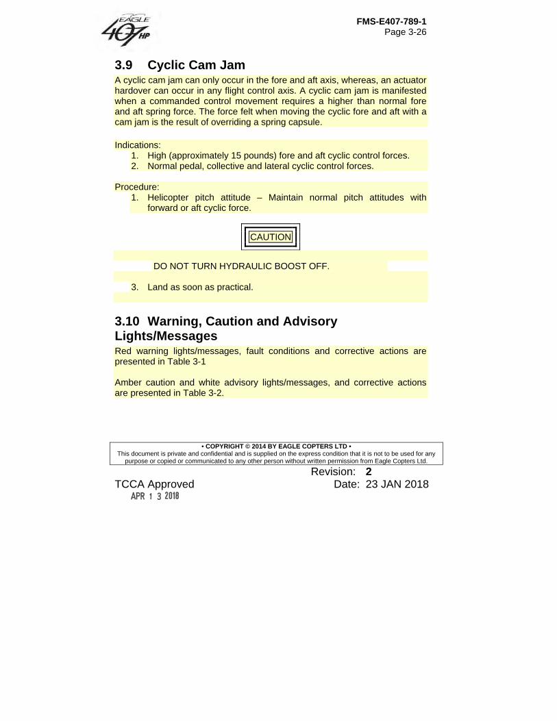
FMS-E407-789-1 Page 3-26
• COPYRIGHT © 2014 BY EAGLE COPTERS LTD • This document is private and confidential and is supplied on the express condition that it is not to be used for any
purpose or copied or communicated to any other person without written permission from Eagle Copters Ltd.
Revision: 2 TCCA Approved Date: 23 JAN 2018
3.9 Cyclic Cam Jam A cyclic cam jam can only occur in the fore and aft axis, whereas, an actuator hardover can occur in any flight control axis. A cyclic cam jam is manifested when a commanded control movement requires a higher than normal fore and aft spring force. The force felt when moving the cyclic fore and aft with a cam jam is the result of overriding a spring capsule. Indications:
1. High (approximately 15 pounds) fore and aft cyclic control forces. 2. Normal pedal, collective and lateral cyclic control forces.
Procedure:
1. Helicopter pitch attitude – Maintain normal pitch attitudes with forward or aft cyclic force.
CAUTION
DO NOT TURN HYDRAULIC BOOST OFF.
3. Land as soon as practical.
3.10 Warning, Caution and Advisory Lights/Messages Red warning lights/messages, fault conditions and corrective actions are presented in Table 3-1 Amber caution and white advisory lights/messages, and corrective actions are presented in Table 3-2.
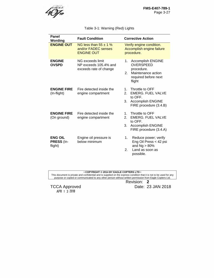
FMS-E407-789-1 Page 3-27
• COPYRIGHT © 2014 BY EAGLE COPTERS LTD • This document is private and confidential and is supplied on the express condition that it is not to be used for any
purpose or copied or communicated to any other person without written permission from Eagle Copters Ltd.
Revision: 2 TCCA Approved Date: 23 JAN 2018
Table 3-1: Warning (Red) Lights
Panel Wording
Fault Condition Corrective Action
ENGINE OUT NG less than 55 ± 1 % and/or FADEC senses ENGINE OUT
Verify engine condition. Accomplish engine failure procedure.
ENGINE OVSPD
NG exceeds limit NP exceeds 105.4% and exceeds rate of change
1. Accomplish ENGINE OVERSPEED procedure.
2. Maintenance action required before next flight
ENGINE FIRE (In-flight)
Fire detected inside the engine compartment
1. Throttle to OFF 2. EMERG. FUEL VALVE
to OFF. 3. Accomplish ENGINE
FIRE procedure (3.4.B)
ENGINE FIRE (On ground)
Fire detected inside the engine compartment
1. Throttle to OFF 2. EMERG. FUEL VALVE
to OFF. 3. Accomplish ENGINE
FIRE procedure (3.4.A)
ENG OIL PRESS (In-flight)
Engine oil pressure is below minimum
1. Reduce power; verify Eng Oil Press < 42 psi and Ng > 80%
2. Land as soon as possible.
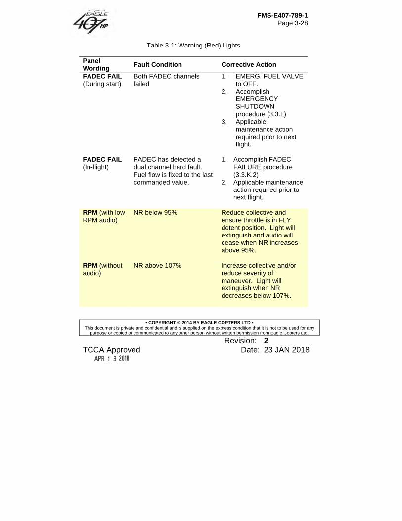
FMS-E407-789-1 Page 3-28
• COPYRIGHT © 2014 BY EAGLE COPTERS LTD • This document is private and confidential and is supplied on the express condition that it is not to be used for any
purpose or copied or communicated to any other person without written permission from Eagle Copters Ltd.
Revision: 2 TCCA Approved Date: 23 JAN 2018
Table 3-1: Warning (Red) Lights
Panel Wording
Fault Condition Corrective Action
FADEC FAIL (During start)
Both FADEC channels failed
1. EMERG. FUEL VALVE to OFF.
2. Accomplish EMERGENCY SHUTDOWN procedure (3.3.L)
3. Applicable maintenance action required prior to next flight.
FADEC FAIL (In-flight)
FADEC has detected a dual channel hard fault. Fuel flow is fixed to the last commanded value.
1. Accomplish FADEC FAILURE procedure (3.3.K.2)
2. Applicable maintenance action required prior to next flight.
RPM (with low RPM audio)
NR below 95% Reduce collective and ensure throttle is in FLY detent position. Light will extinguish and audio will cease when NR increases above 95%.
RPM (without audio)
NR above 107% Increase collective and/or reduce severity of maneuver. Light will extinguish when NR decreases below 107%.
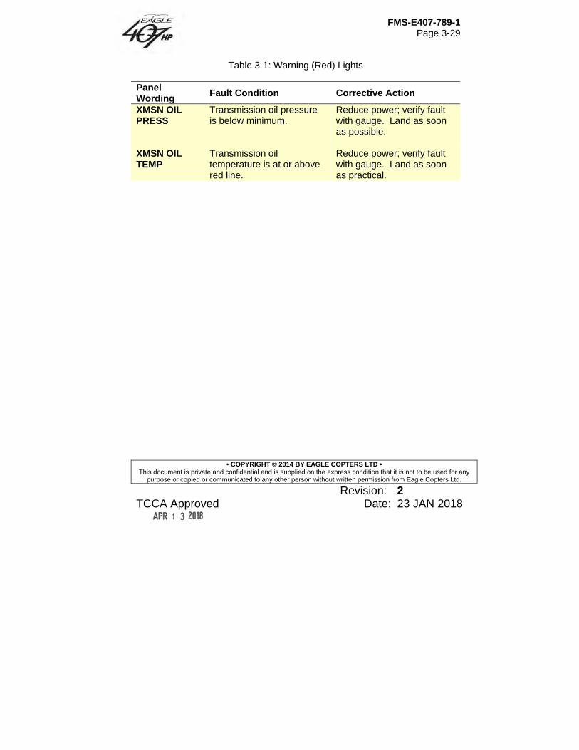
FMS-E407-789-1 Page 3-29
• COPYRIGHT © 2014 BY EAGLE COPTERS LTD • This document is private and confidential and is supplied on the express condition that it is not to be used for any
purpose or copied or communicated to any other person without written permission from Eagle Copters Ltd.
Revision: 2 TCCA Approved Date: 23 JAN 2018
Table 3-1: Warning (Red) Lights
Panel Wording
Fault Condition Corrective Action
XMSN OIL PRESS
Transmission oil pressure is below minimum.
Reduce power; verify fault with gauge. Land as soon as possible.
XMSN OIL TEMP
Transmission oil temperature is at or above red line.
Reduce power; verify fault with gauge. Land as soon as practical.
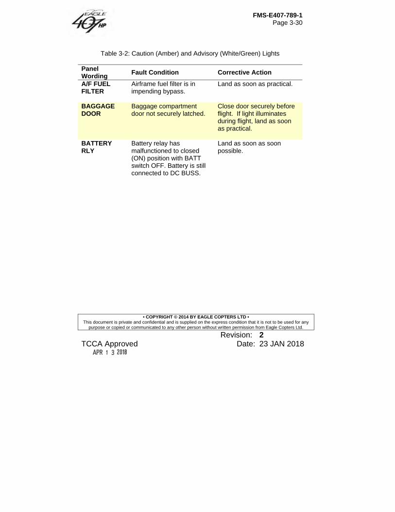
FMS-E407-789-1 Page 3-30
• COPYRIGHT © 2014 BY EAGLE COPTERS LTD • This document is private and confidential and is supplied on the express condition that it is not to be used for any
purpose or copied or communicated to any other person without written permission from Eagle Copters Ltd.
Revision: 2 TCCA Approved Date: 23 JAN 2018
Table 3-2: Caution (Amber) and Advisory (White/Green) Lights
Panel Wording
Fault Condition Corrective Action
A/F FUEL FILTER
Airframe fuel filter is in impending bypass.
Land as soon as practical.
BAGGAGE DOOR
Baggage compartment door not securely latched.
Close door securely before flight. If light illuminates during flight, land as soon as practical.
BATTERY RLY
Battery relay has malfunctioned to closed (ON) position with BATT switch OFF. Battery is still connected to DC BUSS.
Land as soon as soon possible.
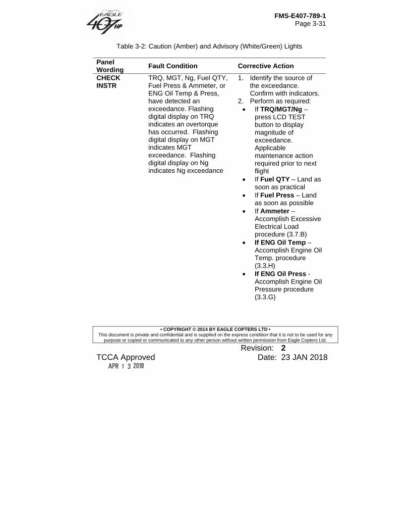
FMS-E407-789-1 Page 3-31
• COPYRIGHT © 2014 BY EAGLE COPTERS LTD • This document is private and confidential and is supplied on the express condition that it is not to be used for any
purpose or copied or communicated to any other person without written permission from Eagle Copters Ltd.
Revision: 2 TCCA Approved Date: 23 JAN 2018
Table 3-2: Caution (Amber) and Advisory (White/Green) Lights
Panel Wording
Fault Condition Corrective Action
CHECK INSTR
TRQ, MGT, Ng, Fuel QTY, Fuel Press & Ammeter, or ENG Oil Temp & Press, have detected an exceedance. Flashing digital display on TRQ indicates an overtorque has occurred. Flashing digital display on MGT indicates MGT exceedance. Flashing digital display on Ng indicates Ng exceedance
1. Identify the source of the exceedance. Confirm with indicators.
2. Perform as required: If TRQ/MGT/Ng –
press LCD TEST button to display magnitude of exceedance. Applicable maintenance action required prior to next flight
If Fuel QTY – Land as soon as practical
If Fuel Press – Land as soon as possible
If Ammeter – Accomplish Excessive Electrical Load procedure (3.7.B)
If ENG Oil Temp – Accomplish Engine Oil Temp. procedure (3.3.H)
If ENG Oil Press -Accomplish Engine Oil Pressure procedure (3.3.G)
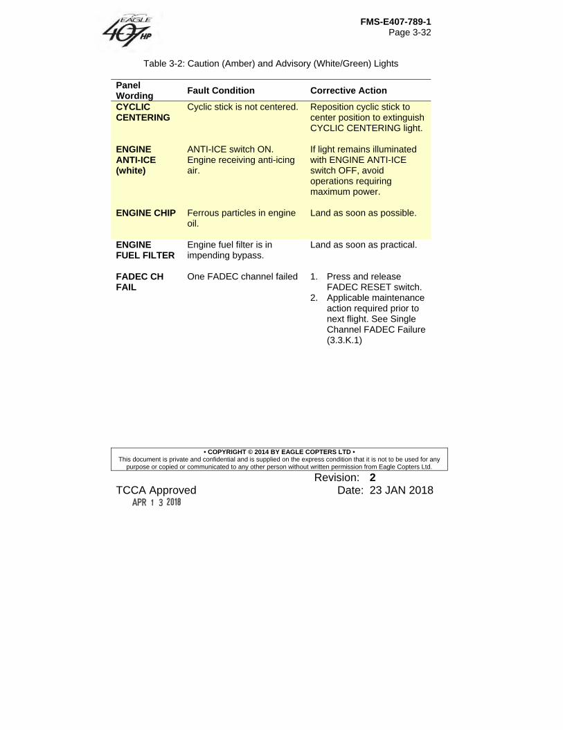
FMS-E407-789-1 Page 3-32
• COPYRIGHT © 2014 BY EAGLE COPTERS LTD • This document is private and confidential and is supplied on the express condition that it is not to be used for any
purpose or copied or communicated to any other person without written permission from Eagle Copters Ltd.
Revision: 2 TCCA Approved Date: 23 JAN 2018
Table 3-2: Caution (Amber) and Advisory (White/Green) Lights
Panel Wording
Fault Condition Corrective Action
CYCLIC CENTERING
Cyclic stick is not centered. Reposition cyclic stick to center position to extinguish CYCLIC CENTERING light.
ENGINE ANTI-ICE (white)
ANTI-ICE switch ON. Engine receiving anti-icing air.
If light remains illuminated with ENGINE ANTI-ICE switch OFF, avoid operations requiring maximum power.
ENGINE CHIP Ferrous particles in engine
oil. Land as soon as possible.
ENGINE FUEL FILTER
Engine fuel filter is in impending bypass.
Land as soon as practical.
FADEC CH FAIL
One FADEC channel failed
1. Press and release FADEC RESET switch.
2. Applicable maintenance action required prior to next flight. See Single Channel FADEC Failure (3.3.K.1)

FMS-E407-789-1 Page 3-33
• COPYRIGHT © 2014 BY EAGLE COPTERS LTD • This document is private and confidential and is supplied on the express condition that it is not to be used for any
purpose or copied or communicated to any other person without written permission from Eagle Copters Ltd.
Revision: 2 TCCA Approved Date: 23 JAN 2018
Table 3-2: Caution (Amber) and Advisory (White/Green) Lights
Panel Wording
Fault Condition Corrective Action
FADEC DEGRADED (In-flight)
FADEC transient operation is degraded which may result in NR (NP) droops and overshoots.
1. Make smooth, non-aggressive control movement.
2. Accomplish FADEC DEGRADED procedure (3.3.K.3)
3. Applicable maintenance action required prior to next flight.
FADEC DEGRADED (With engine shutdown)
FADEC has recorded a fault during previous flight or a current fault has been detected.
Applicable maintenance action required prior to next flight.
FADEC MAINT (In-flight)
Frangible fuse fault. 1. Accomplish FADEC MAINT procedure (3.3.K.4)
2. Applicable maintenance action required prior to next flight
FADEC MAINT (With engine shutdown)
Engine maintenance is required.
Applicable maintenance action required prior to next flight.
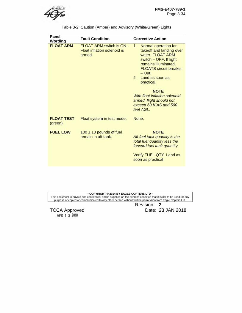
FMS-E407-789-1 Page 3-34
• COPYRIGHT © 2014 BY EAGLE COPTERS LTD • This document is private and confidential and is supplied on the express condition that it is not to be used for any
purpose or copied or communicated to any other person without written permission from Eagle Copters Ltd.
Revision: 2 TCCA Approved Date: 23 JAN 2018
Table 3-2: Caution (Amber) and Advisory (White/Green) Lights
Panel Wording
Fault Condition Corrective Action
FLOAT ARM FLOAT ARM switch is ON. Float inflation solenoid is armed.
1. Normal operation for takeoff and landing over water. FLOAT ARM switch – OFF. If light remains illuminated, FLOATS circuit breaker – Out.
2. Land as soon as practical.
NOTE
With float inflation solenoid armed, flight should not exceed 60 KIAS and 500 feet AGL.
FLOAT TEST (green)
Float system in test mode.
None.
FUEL LOW 100 ± 10 pounds of fuel
remain in aft tank. NOTE
Aft fuel tank quantity is the total fuel quantity less the forward fuel tank quantity Verify FUEL QTY. Land as soon as practical
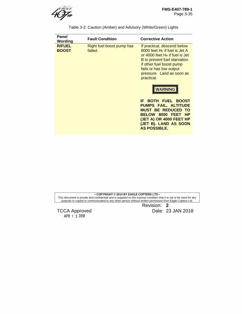
FMS-E407-789-1 Page 3-35
• COPYRIGHT © 2014 BY EAGLE COPTERS LTD • This document is private and confidential and is supplied on the express condition that it is not to be used for any
purpose or copied or communicated to any other person without written permission from Eagle Copters Ltd.
Revision: 2 TCCA Approved Date: 23 JAN 2018
Table 3-2: Caution (Amber) and Advisory (White/Green) Lights
Panel Wording
Fault Condition Corrective Action
R/FUEL BOOST
Right fuel boost pump has failed.
If practical, descend below 8000 feet HP if fuel is Jet A or 4000 feet HP if fuel is Jet B to prevent fuel starvation if other fuel boost pump fails or has low output pressure. Land as soon as practical.
WARNING
IF BOTH FUEL BOOST PUMPS FAIL, ALTITUDE MUST BE REDUCED TO BELOW 8000 FEET HP (JET A) OR 4000 FEET HP (JET B). LAND AS SOON AS POSSIBLE.
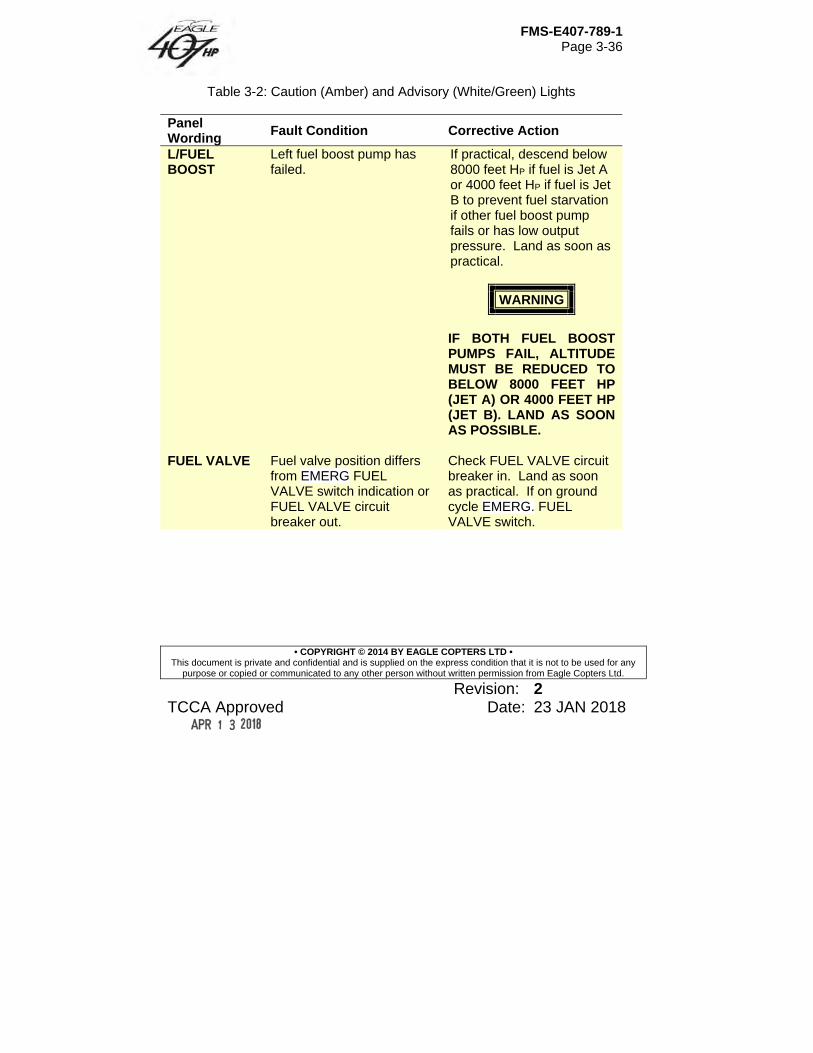
FMS-E407-789-1 Page 3-36
• COPYRIGHT © 2014 BY EAGLE COPTERS LTD • This document is private and confidential and is supplied on the express condition that it is not to be used for any
purpose or copied or communicated to any other person without written permission from Eagle Copters Ltd.
Revision: 2 TCCA Approved Date: 23 JAN 2018
Table 3-2: Caution (Amber) and Advisory (White/Green) Lights
Panel Wording
Fault Condition Corrective Action
L/FUEL BOOST
Left fuel boost pump has failed.
If practical, descend below 8000 feet HP if fuel is Jet A or 4000 feet HP if fuel is Jet B to prevent fuel starvation if other fuel boost pump fails or has low output pressure. Land as soon as practical.
WARNING
IF BOTH FUEL BOOST PUMPS FAIL, ALTITUDE MUST BE REDUCED TO BELOW 8000 FEET HP (JET A) OR 4000 FEET HP (JET B). LAND AS SOON AS POSSIBLE.
FUEL VALVE Fuel valve position differs from EMERG FUEL VALVE switch indication or FUEL VALVE circuit breaker out.
Check FUEL VALVE circuit breaker in. Land as soon as practical. If on ground cycle EMERG. FUEL VALVE switch.
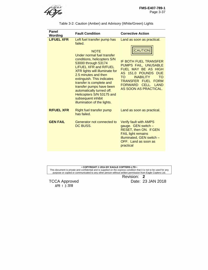
FMS-E407-789-1 Page 3-37
• COPYRIGHT © 2014 BY EAGLE COPTERS LTD • This document is private and confidential and is supplied on the express condition that it is not to be used for any
purpose or copied or communicated to any other person without written permission from Eagle Copters Ltd.
Revision: 2 TCCA Approved Date: 23 JAN 2018
Table 3-2: Caution (Amber) and Advisory (White/Green) Lights
Panel Wording
Fault Condition Corrective Action
L/FUEL XFR Left fuel transfer pump has failed.
NOTE Under normal fuel transfer conditions, helicopters S/N 53000 through 53174 L/FUEL XFR and R/FUEL XFR lights will illuminate for 2.5 minutes and then extinguish. This indicates transfer is complete and transfer pumps have been automatically turned off. Helicopters S/N 53175 and subsequent inhibit illumination of the lights.
Land as soon as practical.
CAUTION
IF BOTH FUEL TRANSFER PUMPS FAIL, UNUSABLE FUEL MAY BE AS HIGH AS 151.0 POUNDS DUE TO INABILITY TO TRANSFER FUEL FORM FORWARD CELL. LAND AS SOON AS PRACTICAL.
R/FUEL XFR Right fuel transfer pump has failed.
Land as soon as practical.
GEN FAIL Generator not connected to
DC BUSS. Verify fault with AMPS gauge. GEN switch – RESET, then ON. If GEN FAIL light remains illuminated, GEN switch – OFF. Land as soon as practical
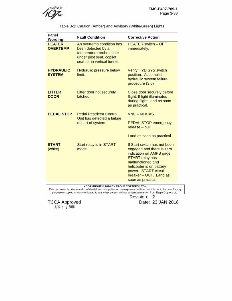
FMS-E407-789-1 Page 3-38
• COPYRIGHT © 2014 BY EAGLE COPTERS LTD • This document is private and confidential and is supplied on the express condition that it is not to be used for any
purpose or copied or communicated to any other person without written permission from Eagle Copters Ltd.
Revision: 2 TCCA Approved Date: 23 JAN 2018
Table 3-2: Caution (Amber) and Advisory (White/Green) Lights
Panel Wording
Fault Condition Corrective Action
HEATER OVERTEMP
An overtemp condition has been detected by a temperature probe either under pilot seat, copilot seat, or in vertical tunnel.
HEATER switch – OFF immediately.
HYDRAULIC SYSTEM
Hydraulic pressure below limit.
Verify HYD SYS switch position. Accomplish hydraulic system failure procedure (3.6)
LITTER DOOR
Litter door not securely latched.
Close door securely before flight. If light illuminates during flight, land as soon as practical.
PEDAL STOP Pedal Restrictor Control
Unit has detected a failure of part of system.
VNE – 60 KIAS PEDAL STOP emergency release – pull. Land as soon as practical.
START (white)
Start relay is in START mode.
If Start switch has not been engaged and there is zero indication on AMPS gage; START relay has malfunctioned and helicopter is on battery power. START circuit breaker – OUT. Land as soon as practical

FMS-E407-789-1 Page 3-39
• COPYRIGHT © 2014 BY EAGLE COPTERS LTD • This document is private and confidential and is supplied on the express condition that it is not to be used for any
purpose or copied or communicated to any other person without written permission from Eagle Copters Ltd.
Revision: 2 TCCA Approved Date: 23 JAN 2018
Table 3-2: Caution (Amber) and Advisory (White/Green) Lights
Panel Wording
Fault Condition Corrective Action
START FAULT
Indicates a starter relay failure. Engine may not start.
Throttle to OFF.
T/R CHIP Ferrous particles in tail rotor gearbox oil.
Land as soon as possible.
XMSN CHIP Ferrous particles in
transmission oil. Land as soon as possible.

FMS-E407-789-1 Page 4-1
• COPYRIGHT © 2014 BY EAGLE COPTERS LTD • This document is private and confidential and is supplied on the express condition that it is not to be used for any
purpose or copied or communicated to any other person without written permission from Eagle Copters Ltd.
Revision: 1 TCCA Approved Date: 23 AUG 2016
Section 4 Performance Data
Table of Contents
4.1 Introduction .......................................................................................... 3 4.2 Power Assurance Check ..................................................................... 3 4.3 Density Altitude .................................................................................... 5 4.4 Height Velocity Envelope ..................................................................... 6 4.5 Hover Ceiling ....................................................................................... 7 4.6 Not Used .............................................................................................. 9 4.7 Climb and Descent .............................................................................. 9 4.7.A Climb ................................................................................................ 9 4.7.B Autorotation.................................................................................... 10 4.8 Airspeed Calibration .......................................................................... 10 4.9 Not Used ............................................................................................ 10 4.10 Noise Levels ...................................................................................... 11 4.10.A FAR Part 36 Stage 2 Noise Level .................................................. 11 4.10.B Canadian Airworthiness Manual Chapter 516 and ICAO Annex 16 Noise Level .................................................................................................... 12
List of Figures Figure 4-1A – Power Assurance Check, Level Flight MGT Chart ................. 13 Figure 4-1B – Power Assurance Check, Level Flight NG Chart.................... 14 Figure 4-2 – Density Altitude ......................................................................... 15 Figure 4-3 – Altitude Versus Gross Weight for Height Velocity Diagram ...... 16 Figure 4-4 – Height Velocity Chart ................................................................ 17 Figure 4-5 ............................................................................................. Deleted Figure 4-6 – IGE Hover Controllability Chart ................................................. 18 Figure 4-7 – OGE Hover Controllability Chart ............................................... 19 Figure 4-8 – Hover Ceiling IGE (Sheet 1 of 4) .............................................. 20 Figure 4-8 – Hover Ceiling IGE (Sheet 2 of 4) .............................................. 21 Figure 4-8 – Hover Ceiling IGE (Sheet 3 of 4) .............................................. 22 Figure 4-8 – Hover Ceiling IGE (Sheet 4 of 4) .............................................. 23 Figure 4-9 – Hover Ceiling OGE (Sheet 1 of 4) ............................................. 24 Figure 4-9 – Hover Ceiling OGE (Sheet 2 of 4) ............................................. 25
FMS-E407-789-1 Page 4-2
• COPYRIGHT © 2014 BY EAGLE COPTERS LTD • This document is private and confidential and is supplied on the express condition that it is not to be used for any
purpose or copied or communicated to any other person without written permission from Eagle Copters Ltd.
Revision: 1 TCCA Approved Date: 23 AUG 2016
Figure 4-9 – Hover Ceiling OGE (Sheet 3 of 4) ............................................. 26 Figure 4-9 – Hover Ceiling OGE (Sheet 4 of 4) ............................................. 27 Figure 4-10 – Rate of Climb – Takeoff Power (Sheet 1 of 12) ...................... 28 Figure 4-10 – Rate of Climb – Takeoff Power (Sheet 2 of 12) ...................... 29 Figure 4-10 – Rate of Climb – Takeoff Power (Sheet 3 of 12) ...................... 30 Figure 4-10 – Rate of Climb – Takeoff Power (Sheet 4 of 12) ...................... 31 Figure 4-10 – Rate of Climb – Takeoff Power (Sheet 5 of 12) ...................... 32 Figure 4-10 – Rate of Climb – Takeoff Power (Sheet 6 of 12) ...................... 33 Figure 4-10 – Rate of Climb – Takeoff Power (Sheet 7 of 12) ...................... 34 Figure 4-10 – Rate of Climb – Takeoff Power (Sheet 8 of 12) ...................... 35 Figure 4-10 – Rate of Climb – Takeoff Power (Sheet 9 of 12) ...................... 36 Figure 4-10 – Rate of Climb – Takeoff Power (Sheet 10 of 12) .................... 37 Figure 4-10 – Rate of Climb – Takeoff Power (Sheet 11 of 12) .................... 38 Figure 4-10 – Rate of Climb – Takeoff Power (Sheet 12 of 12) .................... 39 Figure 4-11 – Rate of Climb – Max Continuous Power (Sheet 1 of 12) ........ 40 Figure 4-11 – Rate of Climb – Max Continuous Power (Sheet 2 of 12) ........ 41 Figure 4-12 – Rate of Climb – Max Continuous Power (Sheet 3 of 12) ........ 42 Figure 4-11 – Rate of Climb – Max Continuous Power (Sheet 4 of 12) ........ 43 Figure 4-11 – Rate of Climb – Max Continuous Power (Sheet 5 of 12) ........ 44 Figure 4-11 – Rate of Climb – Max Continuous Power (Sheet 6 of 12) ........ 45 Figure 4-11 – Rate of Climb – Max Continuous Power (Sheet 7 of 12) ........ 46 Figure 4-11 – Rate of Climb – Max Continuous Power (Sheet 8 of 12) ........ 47 Figure 4-11 – Rate of Climb – Max Continuous Power (Sheet 9 of 12) ........ 48 Figure 4-11 – Rate of Climb – Max Continuous Power (Sheet 10 of 12) ...... 49 Figure 4-11 – Rate of Climb – Max Continuous Power (Sheet 11 of 12) ...... 50 Figure 4-11 – Rate of Climb – Max Continuous Power (Sheet 12 of 12) ...... 51 Figure 4-12 – Autorotation Glide Distance .................................................... 52 Figure 4-13 – Airspeed Installation Correction .............................................. 53
FMS-E407-789-1 Page 4-3
• COPYRIGHT © 2014 BY EAGLE COPTERS LTD • This document is private and confidential and is supplied on the express condition that it is not to be used for any
purpose or copied or communicated to any other person without written permission from Eagle Copters Ltd.
Revision: 1 TCCA Approved Date: 23 AUG 2016
Section 4 Performance Data
4.1 Introduction Performance data presented herein are derived from engine manufacturer's specification power for engine less installation losses. These data are applicable to basic helicopter without any optional equipment that would appreciably affect lift, drag, or power available.
4.2 Power Assurance Check Power Assurance Check Charts (Figure 4-1A and Figure 4-1B) are provided for the Honeywell HTS900-2-1D engine. These charts indicate the maximum allowable MGT and NG for an engine meeting minimum Honeywell specification. Engine must develop required torque without exceeding chart MGT/NG in order to meet performance data contained in this manual. Figure 4-1A is used for checking MGT while in level flight and Figure 4-1B is used for checking NG while in level flight. The charts are applicable with or without the IBF installed per TCCA STC SH16-9/FAA STC SR03706NY. To perform power assurance check, turn off all sources of bleed air, including ENGINE ANTI-ICING. Establish level flight at an airspeed of 85 to 105 KIAS or VNE, whichever is lower.
NOTE
Be sure to dwell at the applicable power conditions in stabilized level flight before taking data.
FMS-E407-789-1 Page 4-4
• COPYRIGHT © 2014 BY EAGLE COPTERS LTD • This document is private and confidential and is supplied on the express condition that it is not to be used for any
purpose or copied or communicated to any other person without written permission from Eagle Copters Ltd.
Revision: 1 TCCA Approved Date: 23 AUG 2016
NOTE
Record pressure altitude to the nearest 100 ft increment.
NOTE
Record OAT and Torque to the most significant digit of the gauges.
NOTE
If PAC value is low, be sure to verify accuracy of aircraft
OAT indication by comparing with airfield data. MGT PAC margin is most sensitive to OAT and Torque
indication errors.
NOTE
Operators are permitted to use the Excel spreadsheet supplied with the aircraft to ease the calculation of PAC
margins. If PAC margins are close to the limits the manual reading of the chart will take precedence.
EXAMPLE: (See Figure 4-1A and 4-1B) Record following information from cockpit instruments:
A. TRQ – 69% B. HP – 3,700 ft C. OAT – 24°C D. MGT – Actual reading E. NG – Actual reading
SOLUTION: Enter Power Assurance Check chart (Figure 4-1A, Power Assurance Check, Level Flight, MGT Chart) at observed Torque (TRQ – 69%), proceed vertically down to intersect HP (3,700 feet), follow horizontally to intersect
FMS-E407-789-1 Page 4-5
• COPYRIGHT © 2014 BY EAGLE COPTERS LTD • This document is private and confidential and is supplied on the express condition that it is not to be used for any
purpose or copied or communicated to any other person without written permission from Eagle Copters Ltd.
Revision: 1 TCCA Approved Date: 23 AUG 2016
indicated OAT (24°C), then drop vertically to read maximum allowable MGT. If actual MGT is less than or equal to chart MGT, engine performance equals or exceeds minimum specification and performance data contained in this manual can be achieved. If actual MGT is greater than chart MGT, engine performance is less than minimum specification and performance data contained in this manual may not be achievable. Refer to ICA-E407-789 to determine cause of low power (high MGT). Enter the Power Assurance Check chart (Figure 4-1B Power Assurance Check, Level Flight NG Chart) at observed Torque (TRQ – 69%), proceed vertically down to intersect HP (3,700 ft), follow horizontally to intersect indicated OAT (24°C), then drop vertically to read maximum NG. If actual NG is less than or equal to chart NG, engine performance equals or exceeds minimum specification and performance data contained in this manual can be achieved. If actual NG is greater than chart NG, engine performance is less than minimum specification and performance data contained in this manual may not be achievable. Refer to ICA-E407-789 to determine cause of low power (high NG).
4.3 Density Altitude A Density Altitude chart (Figure 4-2) is provided to aid in calculation of performance and limitations. HD is an expression of density of air in terms of height above sea level; hence, the less dense the air, the higher the HD. For standard conditions of temperature and pressure, HD is same as HP. As temperature increases above standard for an altitude, HD will also increase to values higher than HP. Figure 4-2 expresses HD as a function of HP and temperature.
FMS-E407-789-1 Page 4-6
• COPYRIGHT © 2014 BY EAGLE COPTERS LTD • This document is private and confidential and is supplied on the express condition that it is not to be used for any
purpose or copied or communicated to any other person without written permission from Eagle Copters Ltd.
Revision: 1 TCCA Approved Date: 23 AUG 2016
Density altitude chart also includes inverse of square root of density ratio:
1
√
which is used to calculate true airspeed (KTAS) by relation:
1
√
EXAMPLE: If ambient temperature is -15°C and pressure altitude is 7000 feet, find density altitude, and true airspeed for 100 KCAS. SOLUTION: Enter bottom of chart at -15°C. Move vertically upward to 7000 foot pressure altitude line. From intersection point, move horizontally left and read density altitude value of 5000 feet.
Move horizontally right and read: √
True airspeed: 100 1.08 108
4.4 Height Velocity Envelope The height-velocity envelope diagrams (Figure 4-3 and Figure 4-4) define conditions from which a safe landing can be made on a smooth, level, firm surface following an engine failure. The Height-Velocity Diagram (Figure 4-3) is valid only when helicopter gross weight does not exceed limits of the Altitude Versus Gross Weight for Height-Velocity Diagram (Figure 4-3). Four envelopes (gross weight regions) are specified. Each gross weight region applies for all gross weights within its boundaries. No interpolation is allowed.
FMS-E407-789-1 Page 4-7
• COPYRIGHT © 2014 BY EAGLE COPTERS LTD • This document is private and confidential and is supplied on the express condition that it is not to be used for any
purpose or copied or communicated to any other person without written permission from Eagle Copters Ltd.
Revision: 1 TCCA Approved Date: 23 AUG 2016
For a given ambient outside air temperature, pressure altitude, and gross weight, the appropriate limiting envelope (Region A, B, C, or D) can be determined. Using Altitude Versus Gross Weight for Height-Velocity Diagram (Figure 4-3), move upward vertically from entry OAT to pressure altitude. From that point, move right horizontally to determine the correct weight region. (Examples: 15°C at sea level at 5000 pounds GW = Region B, and 30°C at 2000 feet pressure altitude at 5000 pounds GW = Region D). Once the correct weight region has been determined (A, B, C, or D), the corresponding avoid area is selected from the Height-Velocity Diagram (Figure 4-4).
4.5 Hover Ceiling NOTE
Hover performance charts are based on 100% rotor
RPM. Hover Ceiling IGE charts (Figure 4-8) and Hover Ceiling OGE charts (Figure 4-9) present hover performance as allowable gross weight for conditions of HP and OAT. These hovering weights are obtainable in zero wind conditions and assume that the heater is not on above 20°C and anti-ice is not on above 5°C. Satisfactory stability and control have been demonstrated in each area of the hover ceiling charts with winds as depicted on the IGE Hover Ceiling Controllability Chart (Figure 4-6) or OGE Hover Ceiling Controllability Chart (Figure 4-7) as applicable. Area A (un-highlighted) of the controllability charts presents hover performance (relative to GW) for conditions where adequate control for all relative wind conditions up to 35 knots for lateral CG not exceeding ±2.5 inches (±63 mm); and up to 17 knots, for lateral CG not exceeding ±4.0 inches (±102 mm); for hover, takeoff and landing. Area B (shaded grey) of the controllability charts present hover performance (relative to CG) for
FMS-E407-789-1 Page 4-8
• COPYRIGHT © 2014 BY EAGLE COPTERS LTD • This document is private and confidential and is supplied on the express condition that it is not to be used for any
purpose or copied or communicated to any other person without written permission from Eagle Copters Ltd.
Revision: 1 TCCA Approved Date: 23 AUG 2016
conditions where adequate control margins exist for relative winds within ±45° of the nose of the helicopter up to 35 knots for lateral CG not exceeding ±2.5 inches (±63 mm); and up to 17 knots for lateral CG not exceeding ±4.0 inches (±102 mm); for hover, takeoff, and landing. Area C (un-highlighted) of the controllability charts present hover performance (relative to C of G) for conditions where adequate control margins exist for winds directly off the helicopter nose for hovering, takeoffs and landings.
NOTE
If lateral CG exceeds ±2.5 inches (±63 mm) and density altitude is above 14,000 feet, all winds should be directly
off the nose of the helicopter; for hover, takeoff and landing.
The following example uses a hover ceiling chart at takeoff power. The example is typical for use with all other hover ceiling charts. EXAMPLE: What guaranteed OGE GW hover capability could be expected for the following conditions: A. HEATER and ANTI ICE — OFF B. HP — 10,000 feet C. OAT — +20°C D. TAKEOFF POWER
FMS-E407-789-1 Page 4-9
• COPYRIGHT © 2014 BY EAGLE COPTERS LTD • This document is private and confidential and is supplied on the express condition that it is not to be used for any
purpose or copied or communicated to any other person without written permission from Eagle Copters Ltd.
Revision: 1 TCCA Approved Date: 23 AUG 2016
SOLUTION: 1) Use Hover Ceiling OGE (Takeoff Power) chart (Figure 4-9, Sheet 1).
A. Enter OAT scale at +20°C. B. Move upward to 10,000 feet HP curve. C. Move horizontally to read maximum gross weight of 5150 Lbs
2) Use the Density Altitude chart (Figure 4-2) A. Enter OAT scale at 20°C B. Move vertically upward to 10,000 ft HP curve C. Move horizontally left to read 12,750 ft HD
3) Use OGE Controllability chart (Figure 4-7) A. Enter DA scale at 12,750 ft HD B. Move horizontally right to the boundary lines C. Move vertically down to read controllability limits for areas A, B and C
Resulting GWs are:
Area A: up to 4550 lbs Area B: 4550 to 4825 lbs Area C: 4825 to 5150 lbs
4.6 Not Used
4.7 Climb and Descent
4.7.A Climb Rate of Climb charts (Figure 4-10 and Figure 4-11) are presented for various combinations of power settings and ENG ANTI ICE switch positions. Recommended best rate of climb airspeed is 60 KIAS. Reduce rate of climb data 100 feet per minute when operating with any combination of door(s) removed.
FMS-E407-789-1 Page 4-10
• COPYRIGHT © 2014 BY EAGLE COPTERS LTD • This document is private and confidential and is supplied on the express condition that it is not to be used for any
purpose or copied or communicated to any other person without written permission from Eagle Copters Ltd.
Revision: 1 TCCA Approved Date: 23 AUG 2016
The following example uses a rate of climb chart at takeoff power. The example is typical for use with all other rate of climb charts. EXAMPLE: Find the maximum rate of climb that can be attained using takeoff power under the following conditions: A. Heater — OFF B. Engine Anti-icing — OFF C. OAT — 10°C D. HP — 14,000 feet E. GW — 3500 pounds SOLUTION: Enter appropriate Rate of Climb Gross Weight chart (Figure 4-10, Sheet 3). At HP scale of 14,000 feet, proceed horizontally to temperature of 10°C. Drop down vertically and read a rate of climb of 1700 feet per minute.
4.7.B Autorotation Refer to Figure 4-12 for autorotational glide distance as a function of altitude.
4.8 Airspeed Calibration Refer to Figure 4-13 for airspeed installation correction during level flight and climb.
4.9 Not Used
FMS-E407-789-1 Page 4-11
• COPYRIGHT © 2014 BY EAGLE COPTERS LTD • This document is private and confidential and is supplied on the express condition that it is not to be used for any
purpose or copied or communicated to any other person without written permission from Eagle Copters Ltd.
Revision: 1 TCCA Approved Date: 23 AUG 2016
4.10 Noise Levels
4.10.A FAR Part 36 Stage 2 Noise Level This aircraft is certified as a Stage 2 helicopter as prescribed in FAR Part 36, Subpart H, for gross weights up to and including the certificated maximum takeoff and landing weight of 5250 pounds (2381 kg) per Bell kit 407-706-020. There are no operating limitations to meet any of the noise requirements. The following noise level complies with FAR Part 36, Appendix J, Stage 2 noise level requirements. It was obtained by analysis of approved data from noise tests conducted under the provisions of FAR Part 36, Amendment 36-20. The certified flyover noise level for the Model 407 is 85.5 dBA SEL (per Bell kit 407-706-020).
NOTE
No determination has been made by the certifying authorities that the noise levels of this helicopter are or should be acceptable or unacceptable for operations at,
into, or out of any airport. VH is defined as the airspeed in level flight obtained using the minimum specification engine torque corresponding to maximum continuous power available for sea level, 25°C (77°F) ambient conditions at the relevant maximum certificated weight. The value of VH thus defined for this helicopter is 127 KTAS.
FMS-E407-789-1 Page 4-12
• COPYRIGHT © 2014 BY EAGLE COPTERS LTD • This document is private and confidential and is supplied on the express condition that it is not to be used for any
purpose or copied or communicated to any other person without written permission from Eagle Copters Ltd.
Revision: 1 TCCA Approved Date: 23 AUG 2016
4.10.B Canadian Airworthiness Manual Chapter 516 and ICAO Annex 16 Noise Level This helicopter complies with the noise emission standards applicable to the aircraft as set out by the International Civil Aviation Organization (ICAO) in Annex 16, Volume 1, Chapter 11, for gross weights up to and including the certificated maximum takeoff and landing weight of 5250 pounds (2381 kg) per Bell kit 407-706-020. There are no operating limitations to meet any of the noise requirements. The following noise level complies with ICAO Annex 16, Volume 1, Chapter 11 noise level requirements. It was obtained by analysis of approved data from noise tests conducted under the provisions of ICAO Annex 16, Volume 1, Third Edition-1993. The flyover noise level for the Model 407 is 85.5 dBA SEL (per Bell kit 407-706-020).
NOTE
ICAO Annex 16, Volume 1, Chapter 11 approval is applicable only after endorsement by the Civil Aviation
Authority of the country of aircraft registration.
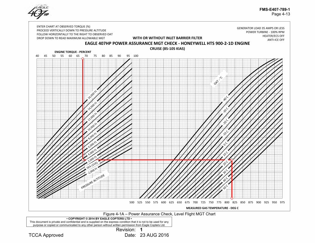
FMS-E407-789-1 Page 4-13
• COPYRIGHT © 2014 BY EAGLE COPTERS LTD • This document is private and confidential and is supplied on the express condition that it is not to be used for any
purpose or copied or communicated to any other person without written permission from Eagle Copters Ltd.
Revision: 1 TCCA Approved Date: 23 AUG 2016
Figure 4-1A – Power Assurance Check, Level Flight MGT Chart
200 225 250 275 300 325 350 375 400 425 450 475 500 525 550 575 600 625 650 675 700 725 750 775 800 825 850 875 900 925 950 975
MEASURED GAS TEMPERATURE ‐ DEG C
WITH OR WITHOUT INLET BARRIER FILTEREAGLE 407HP POWER ASSURANCE MGT CHECK ‐ HONEYWELL HTS 900‐2‐1D ENGINE
CRUISE (85‐105 KIAS)
GENERATOR LOAD 35 AMPS OR LESSPOWER TURBINE ‐ 100% RPM
HEATER/ECS OFFANTI‐ICE OFF
ENTER CHART AT OBSERVED TORQUE (%)PROCEED VERTICALLY DOWN TO PRESSURE ALTITUDEFOLLOW HORIZONTALLY TO THE RIGHT TO OBSERVED OATDROP DOWN TO READ MAXIMUM ALLOWABLE MGT
ENGINE TORQUE ‐ PERCENT40 45 50 55 60 65 70 75 80 85 90 95 100
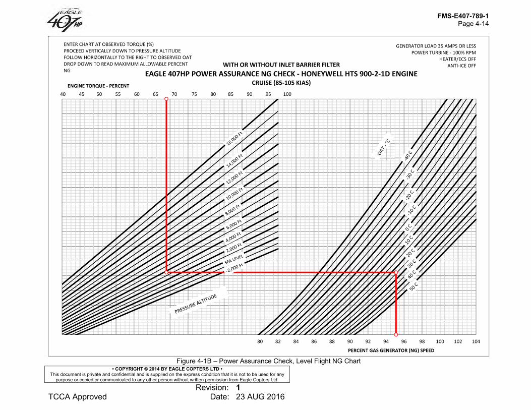
FMS-E407-789-1 Page 4-14
• COPYRIGHT © 2014 BY EAGLE COPTERS LTD • This document is private and confidential and is supplied on the express condition that it is not to be used for any
purpose or copied or communicated to any other person without written permission from Eagle Copters Ltd.
Revision: 1 TCCA Approved Date: 23 AUG 2016
Figure 4-1B – Power Assurance Check, Level Flight NG Chart
58 60 62 64 66 68 70 72 74 76 78 80 82 84 86 88 90 92 94 96 98 100 102 104
PERCENT GAS GENERATOR (NG) SPEED
WITH OR WITHOUT INLET BARRIER FILTEREAGLE 407HP POWER ASSURANCE NG CHECK ‐ HONEYWELL HTS 900‐2‐1D ENGINE
CRUISE (85‐105 KIAS)
GENERATOR LOAD 35 AMPS OR LESSPOWER TURBINE ‐ 100% RPM
HEATER/ECS OFFANTI‐ICE OFF
ENTER CHART AT OBSERVED TORQUE (%)PROCEED VERTICALLY DOWN TO PRESSURE ALTITUDEFOLLOW HORIZONTALLY TO THE RIGHT TO OBSERVED OATDROP DOWN TO READ MAXIMUM ALLOWABLE PERCENT NG
ENGINE TORQUE ‐ PERCENT40 45 50 55 60 65 70 75 80 85 90 95 100
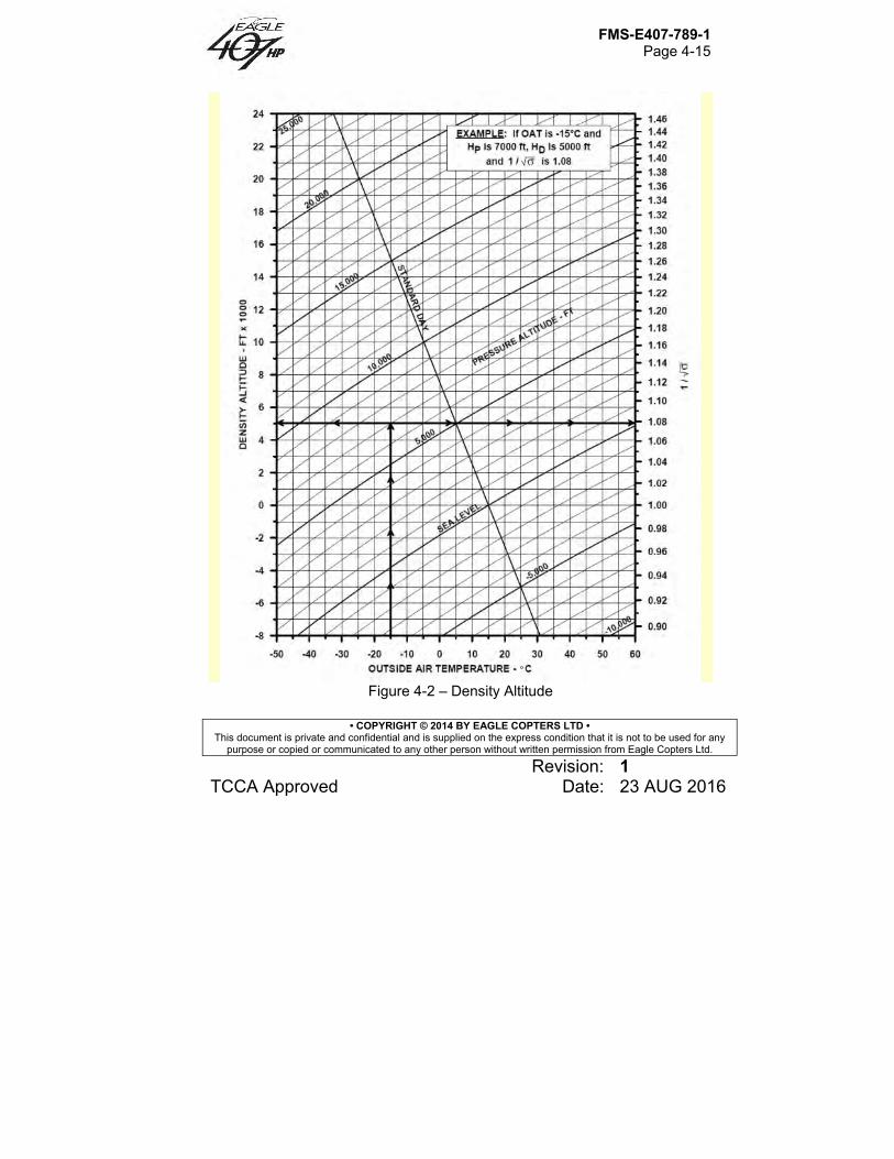
FMS-E407-789-1 Page 4-15
• COPYRIGHT © 2014 BY EAGLE COPTERS LTD • This document is private and confidential and is supplied on the express condition that it is not to be used for any
purpose or copied or communicated to any other person without written permission from Eagle Copters Ltd.
Revision: 1 TCCA Approved Date: 23 AUG 2016
Figure 4-2 – Density Altitude
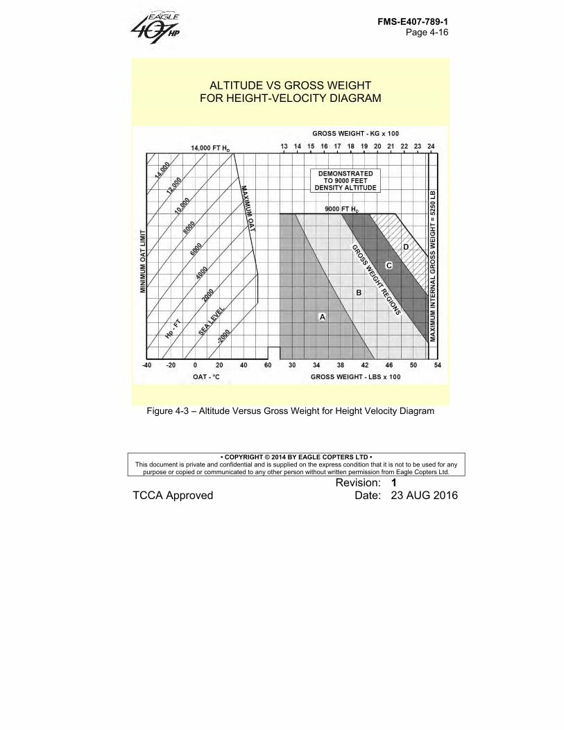
FMS-E407-789-1 Page 4-16
• COPYRIGHT © 2014 BY EAGLE COPTERS LTD • This document is private and confidential and is supplied on the express condition that it is not to be used for any
purpose or copied or communicated to any other person without written permission from Eagle Copters Ltd.
Revision: 1 TCCA Approved Date: 23 AUG 2016
ALTITUDE VS GROSS WEIGHT FOR HEIGHT-VELOCITY DIAGRAM
Figure 4-3 – Altitude Versus Gross Weight for Height Velocity Diagram
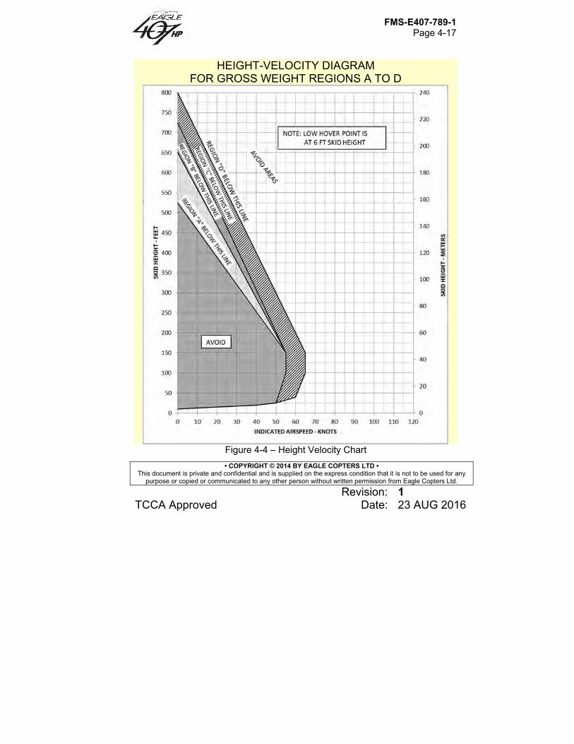
FMS-E407-789-1 Page 4-17
• COPYRIGHT © 2014 BY EAGLE COPTERS LTD • This document is private and confidential and is supplied on the express condition that it is not to be used for any
purpose or copied or communicated to any other person without written permission from Eagle Copters Ltd.
Revision: 1 TCCA Approved Date: 23 AUG 2016
HEIGHT-VELOCITY DIAGRAM FOR GROSS WEIGHT REGIONS A TO D
Figure 4-4 – Height Velocity Chart
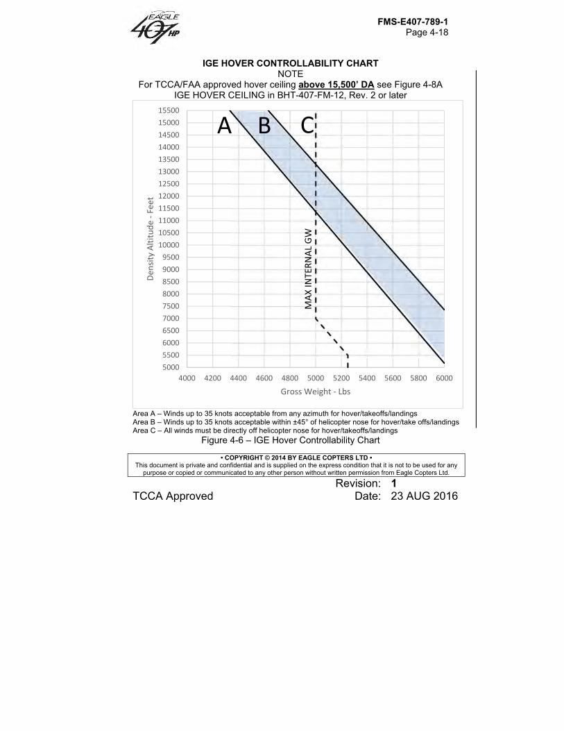
FMS-E407-789-1 Page 4-18
• COPYRIGHT © 2014 BY EAGLE COPTERS LTD • This document is private and confidential and is supplied on the express condition that it is not to be used for any
purpose or copied or communicated to any other person without written permission from Eagle Copters Ltd.
Revision: 1 TCCA Approved Date: 23 AUG 2016
IGE HOVER CONTROLLABILITY CHART NOTE
For TCCA/FAA approved hover ceiling above 15,500’ DA see Figure 4-8A IGE HOVER CEILING in BHT-407-FM-12, Rev. 2 or later
Area A – Winds up to 35 knots acceptable from any azimuth for hover/takeoffs/landings Area B – Winds up to 35 knots acceptable within ±45° of helicopter nose for hover/take offs/landings Area C – All winds must be directly off helicopter nose for hover/takeoffs/landings
Figure 4-6 – IGE Hover Controllability Chart
5000
5500
6000
6500
7000
7500
8000
8500
9000
9500
10000
10500
11000
11500
12000
12500
13000
13500
14000
14500
15000
15500
4000 4200 4400 4600 4800 5000 5200 5400 5600 5800 6000
Den
sity Altitude ‐Feet
Gross Weight ‐ Lbs
A B C
MAXINTERNAL GW
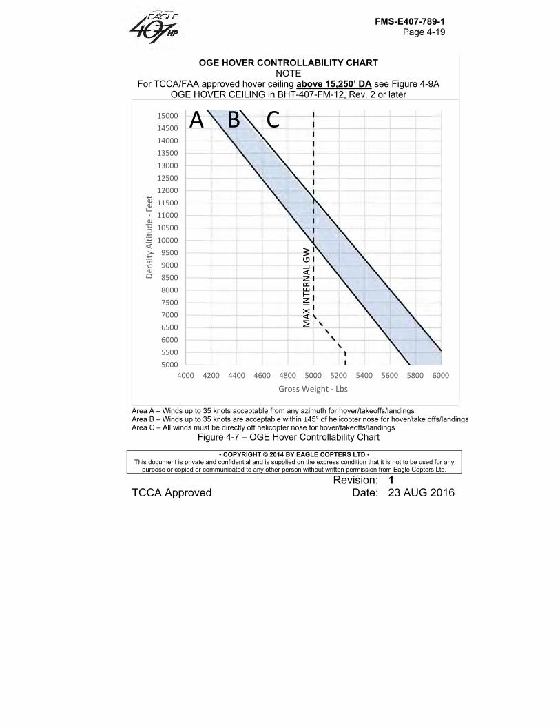
FMS-E407-789-1 Page 4-19
• COPYRIGHT © 2014 BY EAGLE COPTERS LTD • This document is private and confidential and is supplied on the express condition that it is not to be used for any
purpose or copied or communicated to any other person without written permission from Eagle Copters Ltd.
Revision: 1 TCCA Approved Date: 23 AUG 2016
OGE HOVER CONTROLLABILITY CHART NOTE
For TCCA/FAA approved hover ceiling above 15,250’ DA see Figure 4-9A OGE HOVER CEILING in BHT-407-FM-12, Rev. 2 or later
Area A – Winds up to 35 knots acceptable from any azimuth for hover/takeoffs/landings Area B – Winds up to 35 knots are acceptable within ±45° of helicopter nose for hover/take offs/landings Area C – All winds must be directly off helicopter nose for hover/takeoffs/landings
Figure 4-7 – OGE Hover Controllability Chart
5000
5500
6000
6500
7000
7500
8000
8500
9000
9500
10000
10500
11000
11500
12000
12500
13000
13500
14000
14500
15000
4000 4200 4400 4600 4800 5000 5200 5400 5600 5800 6000
Den
sity Altitude ‐Feet
Gross Weight ‐ Lbs
A B C
MAXINTERNAL GW

FMS-E407-789-1 Page 4-20
• COPYRIGHT © 2014 BY EAGLE COPTERS LTD • This document is private and confidential and is supplied on the express condition that it is not to be used for any
purpose or copied or communicated to any other person without written permission from Eagle Copters Ltd.
Revision: 1 TCCA Approved Date: 23 AUG 2016
HOVER CEILING IN GROUND EFFECT
TAKEOFF POWER SKID HEIGHT 4 FT (1.2 METERS) ROTOR RPM 100% HEATER OFF / ANTI-ICE OFF GENERATOR 50 AMPS BASIC INLET
NOTE For TCCA/FAA approved hover ceiling above 15,500’ DA see Figure 4-8A IGE HOVER CEILING (Sheet 1 of 32) in BHT-407-FM-12 Rev. 2 or later
Figure 4-8 – Hover Ceiling IGE (Sheet 1 of 4)
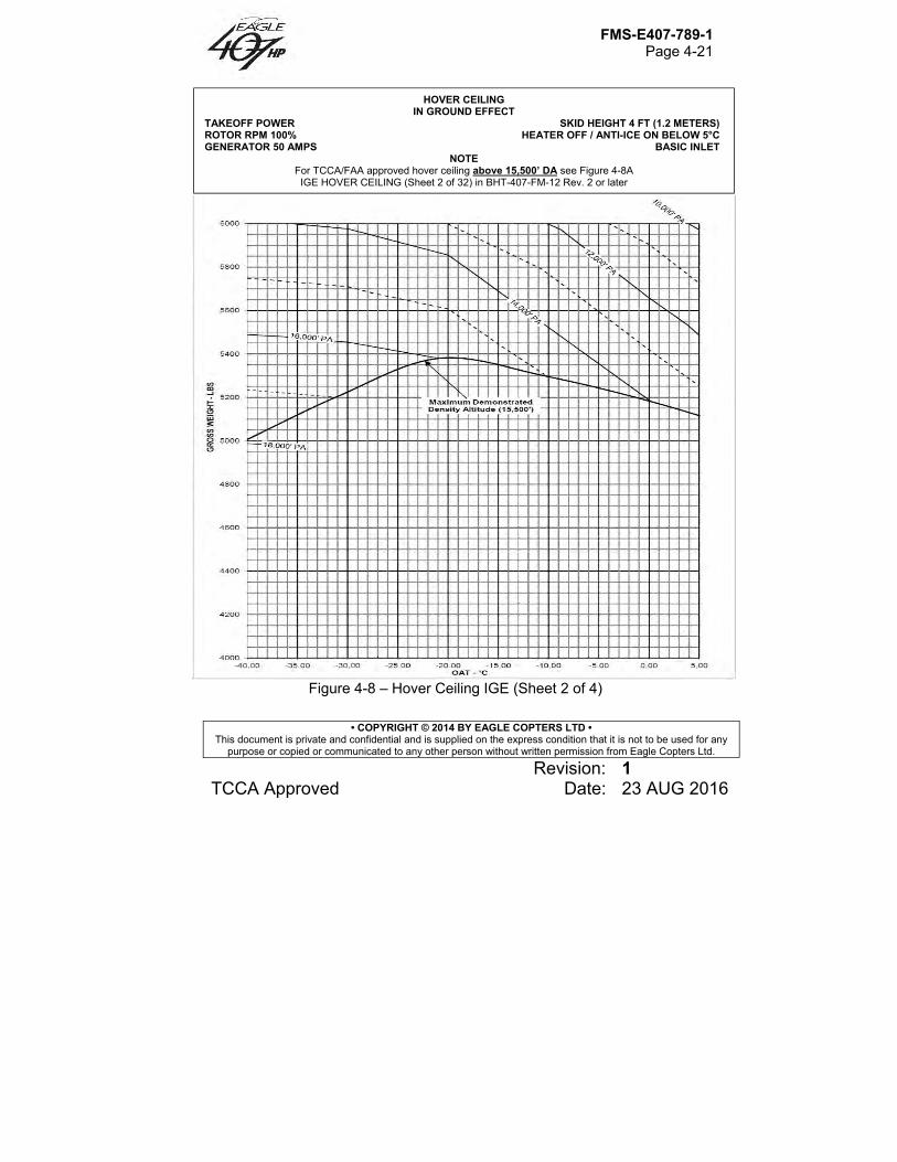
FMS-E407-789-1 Page 4-21
• COPYRIGHT © 2014 BY EAGLE COPTERS LTD • This document is private and confidential and is supplied on the express condition that it is not to be used for any
purpose or copied or communicated to any other person without written permission from Eagle Copters Ltd.
Revision: 1 TCCA Approved Date: 23 AUG 2016
Figure 4-8 – Hover Ceiling IGE (Sheet 2 of 4)
HOVER CEILING IN GROUND EFFECT
TAKEOFF POWER SKID HEIGHT 4 FT (1.2 METERS) ROTOR RPM 100% HEATER OFF / ANTI-ICE ON BELOW 5°C GENERATOR 50 AMPS BASIC INLET
NOTE For TCCA/FAA approved hover ceiling above 15,500’ DA see Figure 4-8A IGE HOVER CEILING (Sheet 2 of 32) in BHT-407-FM-12 Rev. 2 or later
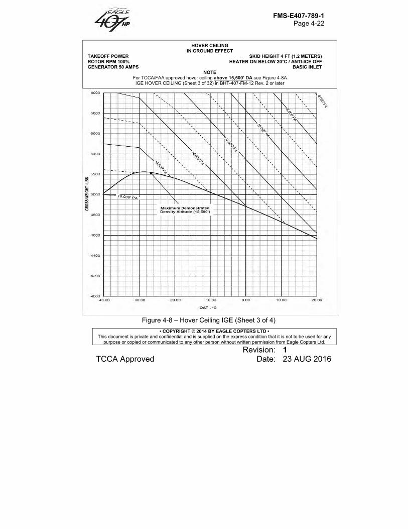
FMS-E407-789-1 Page 4-22
• COPYRIGHT © 2014 BY EAGLE COPTERS LTD • This document is private and confidential and is supplied on the express condition that it is not to be used for any
purpose or copied or communicated to any other person without written permission from Eagle Copters Ltd.
Revision: 1 TCCA Approved Date: 23 AUG 2016
Figure 4-8 – Hover Ceiling IGE (Sheet 3 of 4)
HOVER CEILING IN GROUND EFFECT
TAKEOFF POWER SKID HEIGHT 4 FT (1.2 METERS) ROTOR RPM 100% HEATER ON BELOW 20°C / ANTI-ICE OFF GENERATOR 50 AMPS BASIC INLET
NOTE For TCCA/FAA approved hover ceiling above 15,500’ DA see Figure 4-8A IGE HOVER CEILING (Sheet 3 of 32) in BHT-407-FM-12 Rev. 2 or later
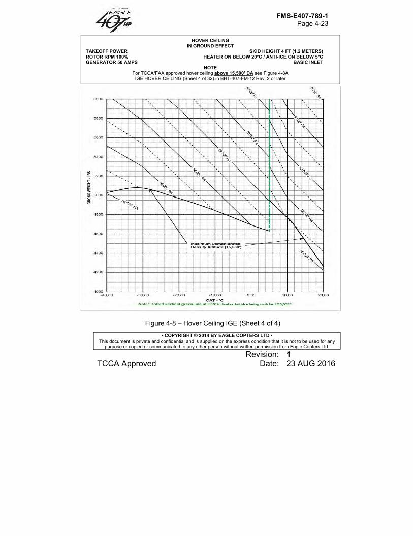
FMS-E407-789-1 Page 4-23
• COPYRIGHT © 2014 BY EAGLE COPTERS LTD • This document is private and confidential and is supplied on the express condition that it is not to be used for any
purpose or copied or communicated to any other person without written permission from Eagle Copters Ltd.
Revision: 1 TCCA Approved Date: 23 AUG 2016
Figure 4-8 – Hover Ceiling IGE (Sheet 4 of 4)
HOVER CEILING IN GROUND EFFECT
TAKEOFF POWER SKID HEIGHT 4 FT (1.2 METERS) ROTOR RPM 100% HEATER ON BELOW 20°C / ANTI-ICE ON BELOW 5°C GENERATOR 50 AMPS BASIC INLET
NOTE For TCCA/FAA approved hover ceiling above 15,500’ DA see Figure 4-8A IGE HOVER CEILING (Sheet 4 of 32) in BHT-407-FM-12 Rev. 2 or later
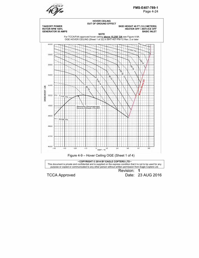
FMS-E407-789-1 Page 4-24
• COPYRIGHT © 2014 BY EAGLE COPTERS LTD • This document is private and confidential and is supplied on the express condition that it is not to be used for any
purpose or copied or communicated to any other person without written permission from Eagle Copters Ltd.
Revision: 1 TCCA Approved Date: 23 AUG 2016
Figure 4-9 – Hover Ceiling OGE (Sheet 1 of 4)
HOVER CEILING OUT OF GROUND EFFECT
TAKEOFF POWER SKID HEIGHT 40 FT (12.2 METERS) ROTOR RPM 100% HEATER OFF / ANTI-ICE OFF GENERATOR 50 AMPS BASIC INLET
NOTE For TCCA/FAA approved hover ceiling above 15,250’ DA see Figure 4-9A OGE HOVER CEILING (Sheet 1 of 32) in BHT-407-FM-12 Rev. 2 or later
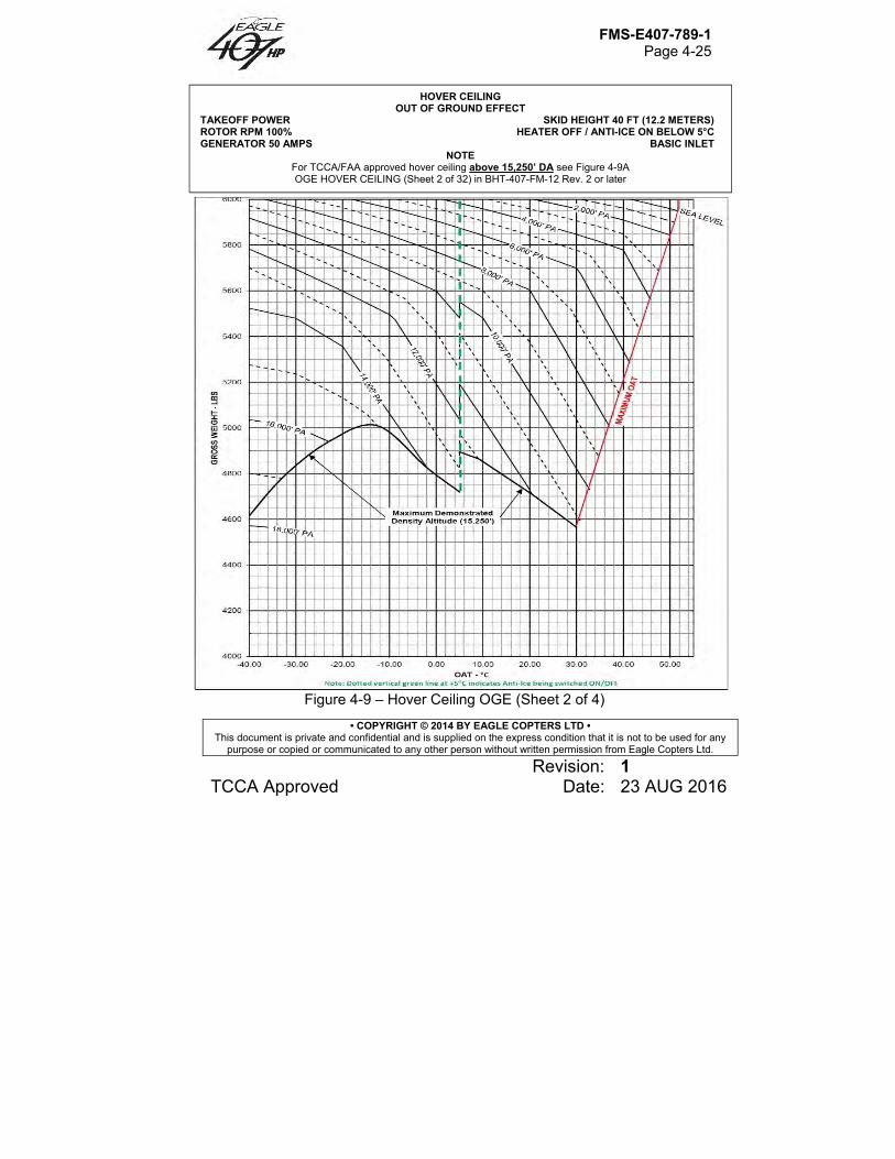
FMS-E407-789-1 Page 4-25
• COPYRIGHT © 2014 BY EAGLE COPTERS LTD • This document is private and confidential and is supplied on the express condition that it is not to be used for any
purpose or copied or communicated to any other person without written permission from Eagle Copters Ltd.
Revision: 1 TCCA Approved Date: 23 AUG 2016
Figure 4-9 – Hover Ceiling OGE (Sheet 2 of 4)
HOVER CEILING OUT OF GROUND EFFECT
TAKEOFF POWER SKID HEIGHT 40 FT (12.2 METERS) ROTOR RPM 100% HEATER OFF / ANTI-ICE ON BELOW 5°C GENERATOR 50 AMPS BASIC INLET
NOTE For TCCA/FAA approved hover ceiling above 15,250’ DA see Figure 4-9A OGE HOVER CEILING (Sheet 2 of 32) in BHT-407-FM-12 Rev. 2 or later
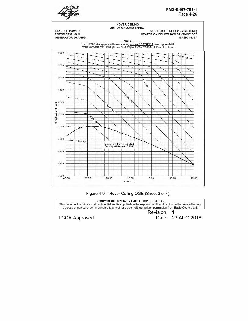
FMS-E407-789-1 Page 4-26
• COPYRIGHT © 2014 BY EAGLE COPTERS LTD • This document is private and confidential and is supplied on the express condition that it is not to be used for any
purpose or copied or communicated to any other person without written permission from Eagle Copters Ltd.
Revision: 1 TCCA Approved Date: 23 AUG 2016
Figure 4-9 – Hover Ceiling OGE (Sheet 3 of 4)
HOVER CEILING OUT OF GROUND EFFECT
TAKEOFF POWER SKID HEIGHT 40 FT (12.2 METERS) ROTOR RPM 100% HEATER ON BELOW 20°C / ANTI-ICE OFF GENERATOR 50 AMPS BASIC INLET
NOTE For TCCA/FAA approved hover ceiling above 15,250’ DA see Figure 4-9A OGE HOVER CEILING (Sheet 3 of 32) in BHT-407-FM-12 Rev. 2 or later
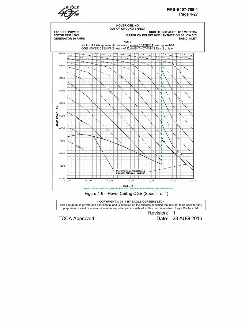
FMS-E407-789-1 Page 4-27
• COPYRIGHT © 2014 BY EAGLE COPTERS LTD • This document is private and confidential and is supplied on the express condition that it is not to be used for any
purpose or copied or communicated to any other person without written permission from Eagle Copters Ltd.
Revision: 1 TCCA Approved Date: 23 AUG 2016
Figure 4-9 – Hover Ceiling OGE (Sheet 4 of 4)
HOVER CEILING OUT OF GROUND EFFECT
TAKEOFF POWER SKID HEIGHT 40 FT (12.2 METERS) ROTOR RPM 100% HEATER ON BELOW 20°C / ANTI-ICE ON BELOW 5°C GENERATOR 50 AMPS BASIC INLET
NOTE For TCCA/FAA approved hover ceiling above 15,250’ DA see Figure 4-9A OGE HOVER CEILING (Sheet 4 of 32) in BHT-407-FM-12 Rev. 2 or later
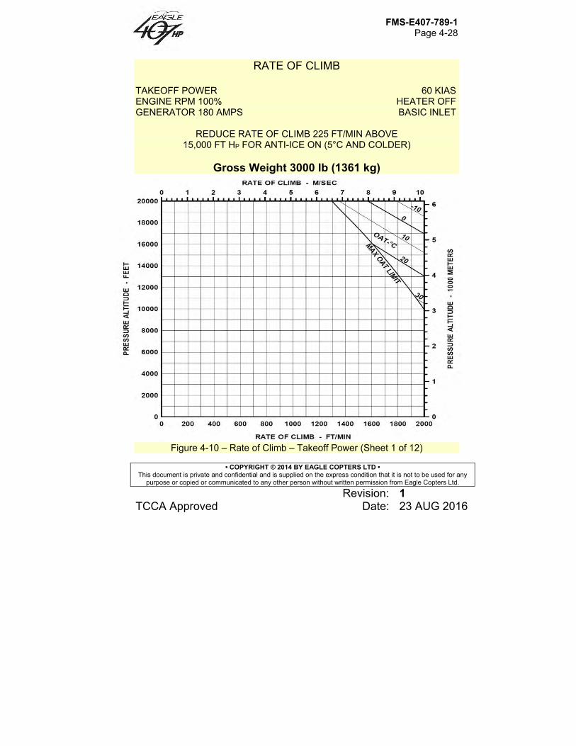
FMS-E407-789-1 Page 4-28
• COPYRIGHT © 2014 BY EAGLE COPTERS LTD • This document is private and confidential and is supplied on the express condition that it is not to be used for any
purpose or copied or communicated to any other person without written permission from Eagle Copters Ltd.
Revision: 1 TCCA Approved Date: 23 AUG 2016
RATE OF CLIMB TAKEOFF POWER 60 KIAS ENGINE RPM 100% HEATER OFF GENERATOR 180 AMPS BASIC INLET
REDUCE RATE OF CLIMB 225 FT/MIN ABOVE 15,000 FT HP FOR ANTI-ICE ON (5°C AND COLDER)
Gross Weight 3000 lb (1361 kg)
Figure 4-10 – Rate of Climb – Takeoff Power (Sheet 1 of 12)
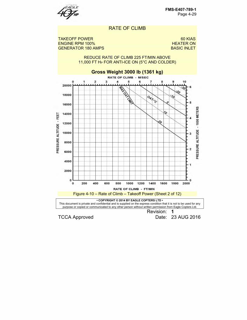
FMS-E407-789-1 Page 4-29
• COPYRIGHT © 2014 BY EAGLE COPTERS LTD • This document is private and confidential and is supplied on the express condition that it is not to be used for any
purpose or copied or communicated to any other person without written permission from Eagle Copters Ltd.
Revision: 1 TCCA Approved Date: 23 AUG 2016
RATE OF CLIMB TAKEOFF POWER 60 KIAS ENGINE RPM 100% HEATER ON GENERATOR 180 AMPS BASIC INLET
REDUCE RATE OF CLIMB 225 FT/MIN ABOVE 11,000 FT HP FOR ANTI-ICE ON (5°C AND COLDER)
Gross Weight 3000 lb (1361 kg)
Figure 4-10 – Rate of Climb – Takeoff Power (Sheet 2 of 12)
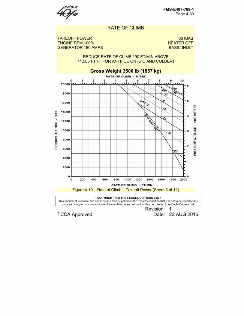
FMS-E407-789-1 Page 4-30
• COPYRIGHT © 2014 BY EAGLE COPTERS LTD • This document is private and confidential and is supplied on the express condition that it is not to be used for any
purpose or copied or communicated to any other person without written permission from Eagle Copters Ltd.
Revision: 1 TCCA Approved Date: 23 AUG 2016
RATE OF CLIMB TAKEOFF POWER 60 KIAS ENGINE RPM 100% HEATER OFF GENERATOR 180 AMPS BASIC INLET
REDUCE RATE OF CLIMB 190 FT/MIN ABOVE 11,500 FT HP FOR ANTI-ICE ON (5°C AND COLDER)
Gross Weight 3500 lb (1857 kg)
Figure 4-10 – Rate of Climb – Takeoff Power (Sheet 3 of 12)
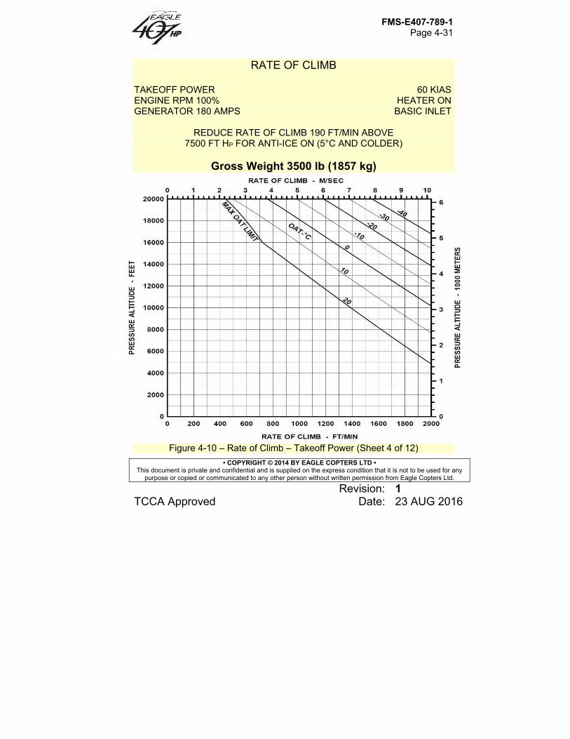
FMS-E407-789-1 Page 4-31
• COPYRIGHT © 2014 BY EAGLE COPTERS LTD • This document is private and confidential and is supplied on the express condition that it is not to be used for any
purpose or copied or communicated to any other person without written permission from Eagle Copters Ltd.
Revision: 1 TCCA Approved Date: 23 AUG 2016
RATE OF CLIMB TAKEOFF POWER 60 KIAS ENGINE RPM 100% HEATER ON GENERATOR 180 AMPS BASIC INLET
REDUCE RATE OF CLIMB 190 FT/MIN ABOVE 7500 FT HP FOR ANTI-ICE ON (5°C AND COLDER)
Gross Weight 3500 lb (1857 kg)
Figure 4-10 – Rate of Climb – Takeoff Power (Sheet 4 of 12)
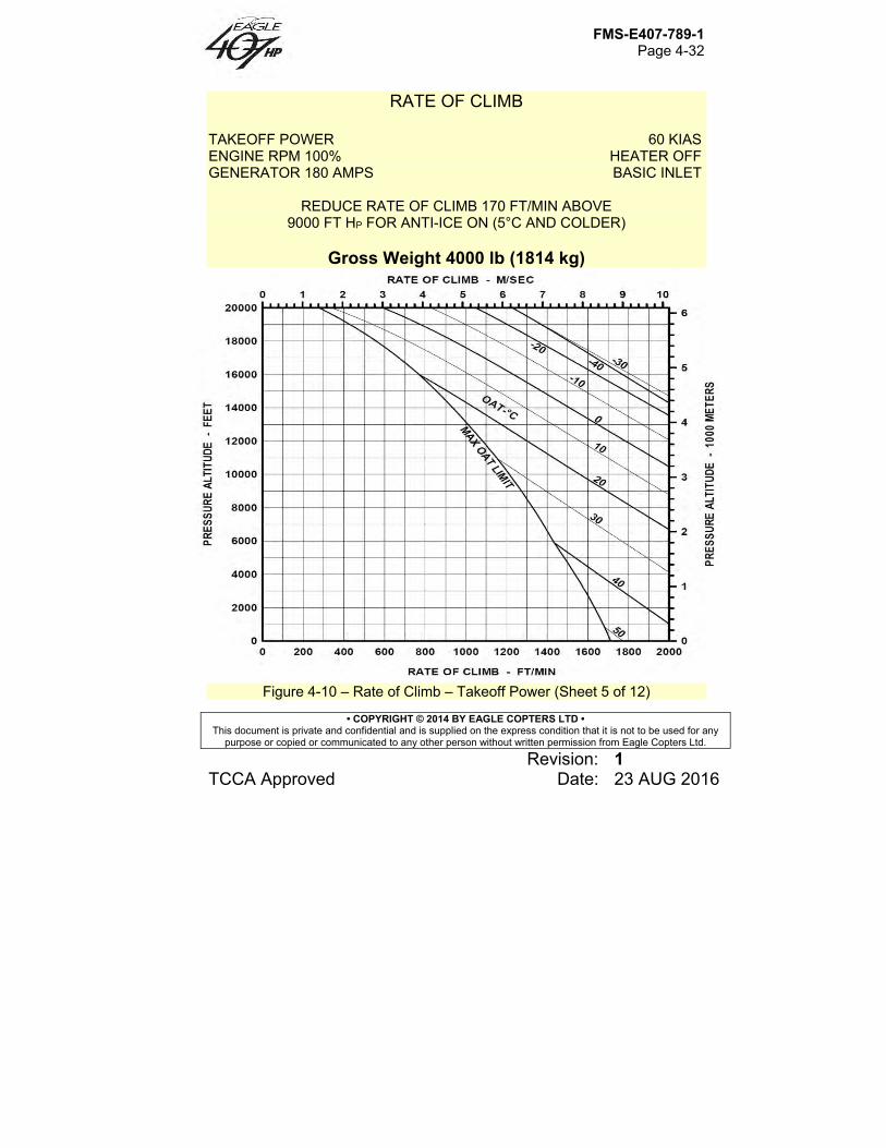
FMS-E407-789-1 Page 4-32
• COPYRIGHT © 2014 BY EAGLE COPTERS LTD • This document is private and confidential and is supplied on the express condition that it is not to be used for any
purpose or copied or communicated to any other person without written permission from Eagle Copters Ltd.
Revision: 1 TCCA Approved Date: 23 AUG 2016
RATE OF CLIMB TAKEOFF POWER 60 KIAS ENGINE RPM 100% HEATER OFF GENERATOR 180 AMPS BASIC INLET
REDUCE RATE OF CLIMB 170 FT/MIN ABOVE 9000 FT HP FOR ANTI-ICE ON (5°C AND COLDER)
Gross Weight 4000 lb (1814 kg)
Figure 4-10 – Rate of Climb – Takeoff Power (Sheet 5 of 12)
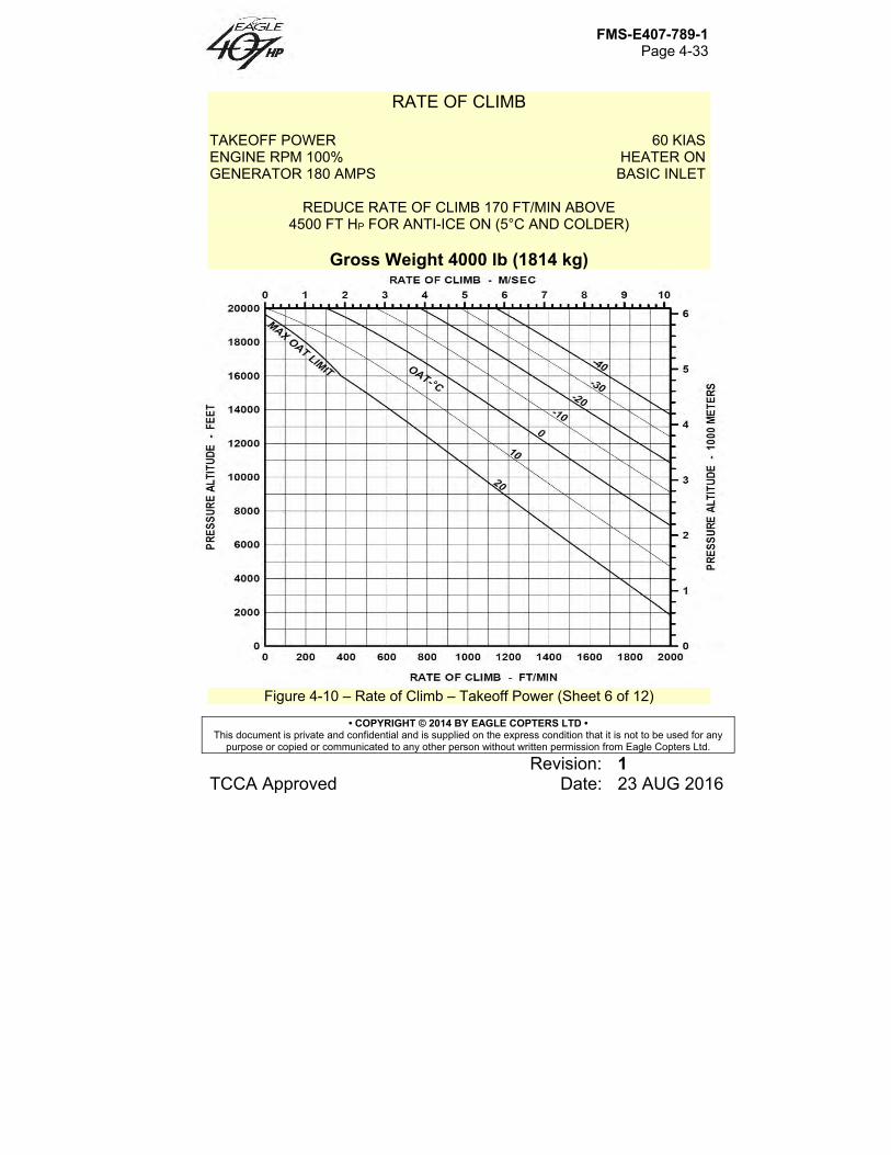
FMS-E407-789-1 Page 4-33
• COPYRIGHT © 2014 BY EAGLE COPTERS LTD • This document is private and confidential and is supplied on the express condition that it is not to be used for any
purpose or copied or communicated to any other person without written permission from Eagle Copters Ltd.
Revision: 1 TCCA Approved Date: 23 AUG 2016
RATE OF CLIMB TAKEOFF POWER 60 KIAS ENGINE RPM 100% HEATER ON GENERATOR 180 AMPS BASIC INLET
REDUCE RATE OF CLIMB 170 FT/MIN ABOVE 4500 FT HP FOR ANTI-ICE ON (5°C AND COLDER)
Gross Weight 4000 lb (1814 kg)
Figure 4-10 – Rate of Climb – Takeoff Power (Sheet 6 of 12)
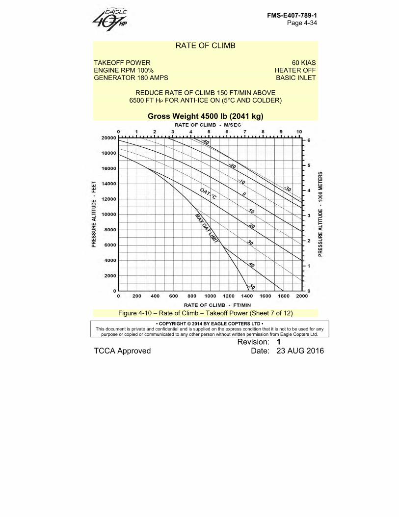
FMS-E407-789-1 Page 4-34
• COPYRIGHT © 2014 BY EAGLE COPTERS LTD • This document is private and confidential and is supplied on the express condition that it is not to be used for any
purpose or copied or communicated to any other person without written permission from Eagle Copters Ltd.
Revision: 1 TCCA Approved Date: 23 AUG 2016
RATE OF CLIMB TAKEOFF POWER 60 KIAS ENGINE RPM 100% HEATER OFF GENERATOR 180 AMPS BASIC INLET
REDUCE RATE OF CLIMB 150 FT/MIN ABOVE 6500 FT HP FOR ANTI-ICE ON (5°C AND COLDER)
Gross Weight 4500 lb (2041 kg)
Figure 4-10 – Rate of Climb – Takeoff Power (Sheet 7 of 12)
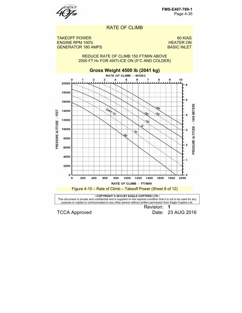
FMS-E407-789-1 Page 4-35
• COPYRIGHT © 2014 BY EAGLE COPTERS LTD • This document is private and confidential and is supplied on the express condition that it is not to be used for any
purpose or copied or communicated to any other person without written permission from Eagle Copters Ltd.
Revision: 1 TCCA Approved Date: 23 AUG 2016
RATE OF CLIMB TAKEOFF POWER 60 KIAS ENGINE RPM 100% HEATER ON GENERATOR 180 AMPS BASIC INLET
REDUCE RATE OF CLIMB 150 FT/MIN ABOVE 2000 FT HP FOR ANTI-ICE ON (5°C AND COLDER)
Gross Weight 4500 lb (2041 kg)
Figure 4-10 – Rate of Climb – Takeoff Power (Sheet 8 of 12)
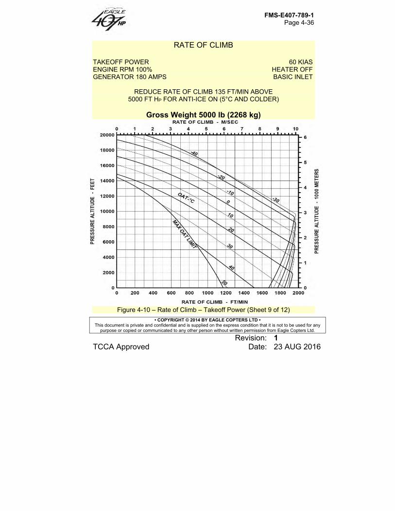
FMS-E407-789-1 Page 4-36
• COPYRIGHT © 2014 BY EAGLE COPTERS LTD • This document is private and confidential and is supplied on the express condition that it is not to be used for any
purpose or copied or communicated to any other person without written permission from Eagle Copters Ltd.
Revision: 1 TCCA Approved Date: 23 AUG 2016
RATE OF CLIMB TAKEOFF POWER 60 KIAS ENGINE RPM 100% HEATER OFF GENERATOR 180 AMPS BASIC INLET
REDUCE RATE OF CLIMB 135 FT/MIN ABOVE 5000 FT HP FOR ANTI-ICE ON (5°C AND COLDER)
Gross Weight 5000 lb (2268 kg)
Figure 4-10 – Rate of Climb – Takeoff Power (Sheet 9 of 12)
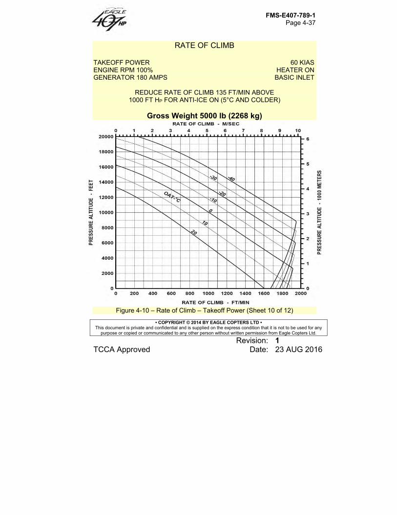
FMS-E407-789-1 Page 4-37
• COPYRIGHT © 2014 BY EAGLE COPTERS LTD • This document is private and confidential and is supplied on the express condition that it is not to be used for any
purpose or copied or communicated to any other person without written permission from Eagle Copters Ltd.
Revision: 1 TCCA Approved Date: 23 AUG 2016
RATE OF CLIMB TAKEOFF POWER 60 KIAS ENGINE RPM 100% HEATER ON GENERATOR 180 AMPS BASIC INLET
REDUCE RATE OF CLIMB 135 FT/MIN ABOVE 1000 FT HP FOR ANTI-ICE ON (5°C AND COLDER)
Gross Weight 5000 lb (2268 kg)
Figure 4-10 – Rate of Climb – Takeoff Power (Sheet 10 of 12)

FMS-E407-789-1 Page 4-38
• COPYRIGHT © 2014 BY EAGLE COPTERS LTD • This document is private and confidential and is supplied on the express condition that it is not to be used for any
purpose or copied or communicated to any other person without written permission from Eagle Copters Ltd.
Revision: 1 TCCA Approved Date: 23 AUG 2016
RATE OF CLIMB TAKEOFF POWER 60 KIAS ENGINE RPM 100% HEATER OFF GENERATOR 180 AMPS BASIC INLET
REDUCE RATE OF CLIMB 130 FT/MIN ABOVE 4000 FT HP FOR ANTI-ICE ON (5°C AND COLDER)
Gross Weight 5250 lb (2381 kg)
Figure 4-10 – Rate of Climb – Takeoff Power (Sheet 11 of 12)
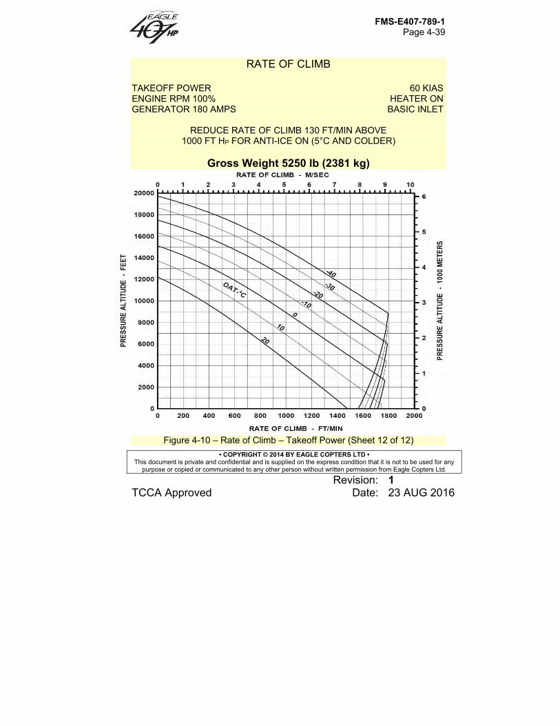
FMS-E407-789-1 Page 4-39
• COPYRIGHT © 2014 BY EAGLE COPTERS LTD • This document is private and confidential and is supplied on the express condition that it is not to be used for any
purpose or copied or communicated to any other person without written permission from Eagle Copters Ltd.
Revision: 1 TCCA Approved Date: 23 AUG 2016
RATE OF CLIMB TAKEOFF POWER 60 KIAS ENGINE RPM 100% HEATER ON GENERATOR 180 AMPS BASIC INLET
REDUCE RATE OF CLIMB 130 FT/MIN ABOVE 1000 FT HP FOR ANTI-ICE ON (5°C AND COLDER)
Gross Weight 5250 lb (2381 kg)
Figure 4-10 – Rate of Climb – Takeoff Power (Sheet 12 of 12)
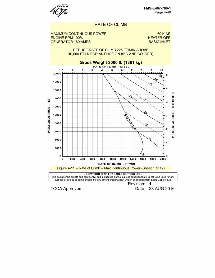
FMS-E407-789-1 Page 4-40
• COPYRIGHT © 2014 BY EAGLE COPTERS LTD • This document is private and confidential and is supplied on the express condition that it is not to be used for any
purpose or copied or communicated to any other person without written permission from Eagle Copters Ltd.
Revision: 1 TCCA Approved Date: 23 AUG 2016
RATE OF CLIMB MAXIMUM CONTINUOUS POWER 60 KIAS ENGINE RPM 100% HEATER OFF GENERATOR 180 AMPS BASIC INLET
REDUCE RATE OF CLIMB 225 FT/MIN ABOVE 10,000 FT HP FOR ANTI-ICE ON (5°C AND COLDER)
Gross Weight 3000 lb (1361 kg)
Figure 4-11 – Rate of Climb – Max Continuous Power (Sheet 1 of 12)
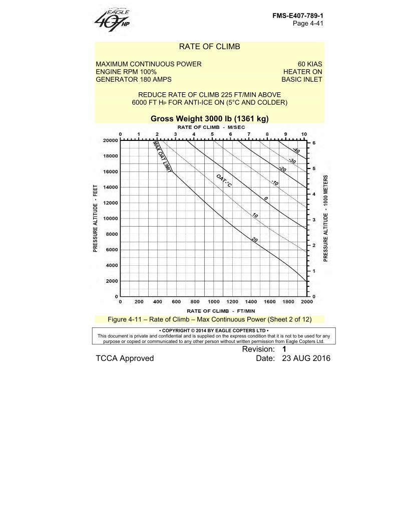
FMS-E407-789-1 Page 4-41
• COPYRIGHT © 2014 BY EAGLE COPTERS LTD • This document is private and confidential and is supplied on the express condition that it is not to be used for any
purpose or copied or communicated to any other person without written permission from Eagle Copters Ltd.
Revision: 1 TCCA Approved Date: 23 AUG 2016
RATE OF CLIMB MAXIMUM CONTINUOUS POWER 60 KIAS ENGINE RPM 100% HEATER ON GENERATOR 180 AMPS BASIC INLET
REDUCE RATE OF CLIMB 225 FT/MIN ABOVE 6000 FT HP FOR ANTI-ICE ON (5°C AND COLDER)
Gross Weight 3000 lb (1361 kg)
Figure 4-11 – Rate of Climb – Max Continuous Power (Sheet 2 of 12)
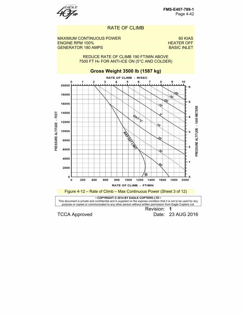
FMS-E407-789-1 Page 4-42
• COPYRIGHT © 2014 BY EAGLE COPTERS LTD • This document is private and confidential and is supplied on the express condition that it is not to be used for any
purpose or copied or communicated to any other person without written permission from Eagle Copters Ltd.
Revision: 1 TCCA Approved Date: 23 AUG 2016
RATE OF CLIMB MAXIMUM CONTINUOUS POWER 60 KIAS ENGINE RPM 100% HEATER OFF GENERATOR 180 AMPS BASIC INLET
REDUCE RATE OF CLIMB 190 FT/MIN ABOVE 7500 FT HP FOR ANTI-ICE ON (5°C AND COLDER)
Gross Weight 3500 lb (1587 kg)
Figure 4-12 – Rate of Climb – Max Continuous Power (Sheet 3 of 12)

FMS-E407-789-1 Page 4-43
• COPYRIGHT © 2014 BY EAGLE COPTERS LTD • This document is private and confidential and is supplied on the express condition that it is not to be used for any
purpose or copied or communicated to any other person without written permission from Eagle Copters Ltd.
Revision: 1 TCCA Approved Date: 23 AUG 2016
RATE OF CLIMB MAXIMUM CONTINUOUS POWER 60 KIAS ENGINE RPM 100% HEATER ON GENERATOR 180 AMPS BASIC INLET
REDUCE RATE OF CLIMB 190 FT/MIN ABOVE 2500 FT HP FOR ANTI-ICE ON (5°C AND COLDER)
Gross Weight 3500 lb (1587 kg)
Figure 4-11 – Rate of Climb – Max Continuous Power (Sheet 4 of 12)
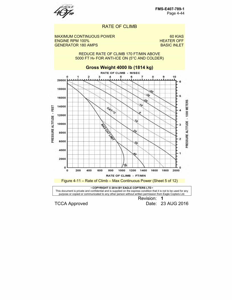
FMS-E407-789-1 Page 4-44
• COPYRIGHT © 2014 BY EAGLE COPTERS LTD • This document is private and confidential and is supplied on the express condition that it is not to be used for any
purpose or copied or communicated to any other person without written permission from Eagle Copters Ltd.
Revision: 1 TCCA Approved Date: 23 AUG 2016
RATE OF CLIMB MAXIMUM CONTINUOUS POWER 60 KIAS ENGINE RPM 100% HEATER OFF GENERATOR 180 AMPS BASIC INLET
REDUCE RATE OF CLIMB 170 FT/MIN ABOVE 5000 FT HP FOR ANTI-ICE ON (5°C AND COLDER)
Gross Weight 4000 lb (1814 kg)
Figure 4-11 – Rate of Climb – Max Continuous Power (Sheet 5 of 12)
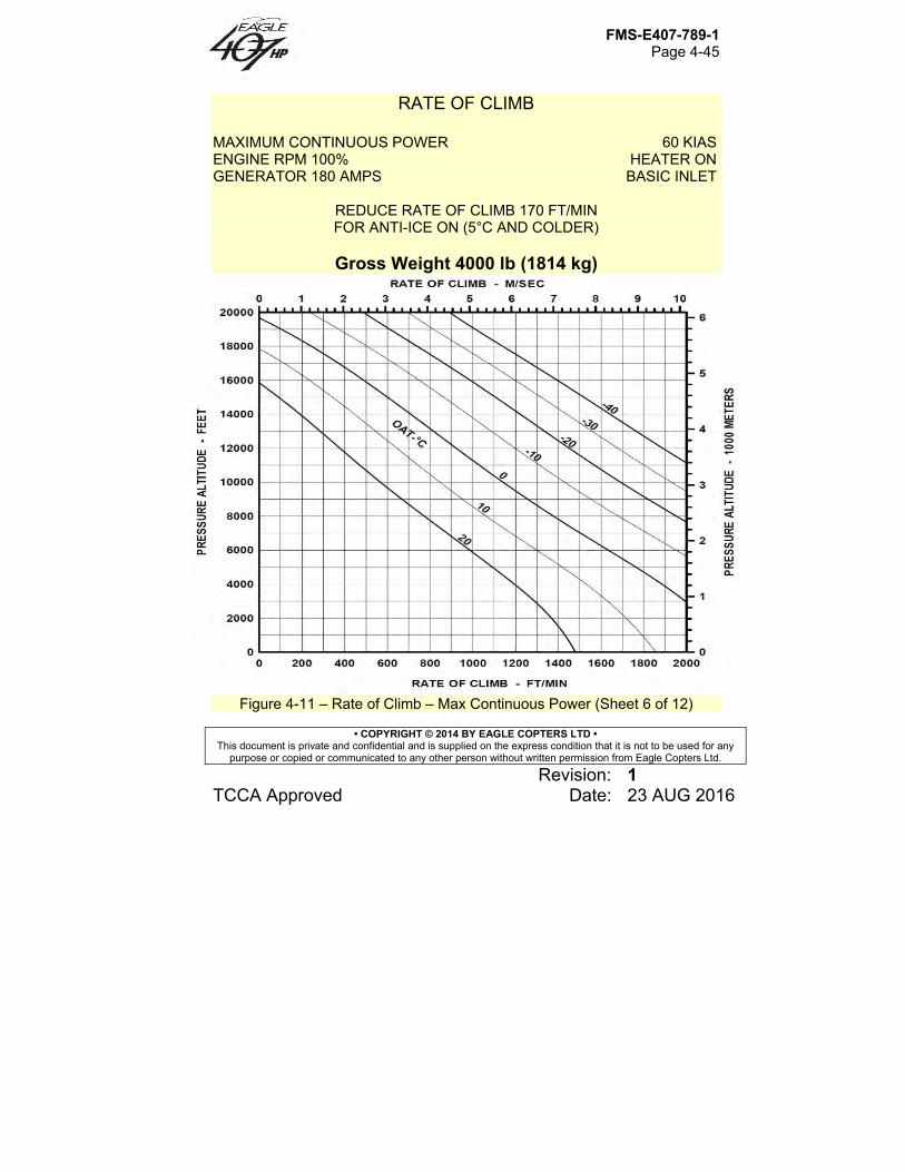
FMS-E407-789-1 Page 4-45
• COPYRIGHT © 2014 BY EAGLE COPTERS LTD • This document is private and confidential and is supplied on the express condition that it is not to be used for any
purpose or copied or communicated to any other person without written permission from Eagle Copters Ltd.
Revision: 1 TCCA Approved Date: 23 AUG 2016
RATE OF CLIMB MAXIMUM CONTINUOUS POWER 60 KIAS ENGINE RPM 100% HEATER ON GENERATOR 180 AMPS BASIC INLET
REDUCE RATE OF CLIMB 170 FT/MIN FOR ANTI-ICE ON (5°C AND COLDER)
Gross Weight 4000 lb (1814 kg)
Figure 4-11 – Rate of Climb – Max Continuous Power (Sheet 6 of 12)
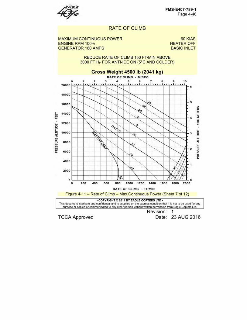
FMS-E407-789-1 Page 4-46
• COPYRIGHT © 2014 BY EAGLE COPTERS LTD • This document is private and confidential and is supplied on the express condition that it is not to be used for any
purpose or copied or communicated to any other person without written permission from Eagle Copters Ltd.
Revision: 1 TCCA Approved Date: 23 AUG 2016
RATE OF CLIMB MAXIMUM CONTINUOUS POWER 60 KIAS ENGINE RPM 100% HEATER OFF GENERATOR 180 AMPS BASIC INLET
REDUCE RATE OF CLIMB 150 FT/MIN ABOVE 3000 FT HP FOR ANTI-ICE ON (5°C AND COLDER)
Gross Weight 4500 lb (2041 kg)
Figure 4-11 – Rate of Climb – Max Continuous Power (Sheet 7 of 12)
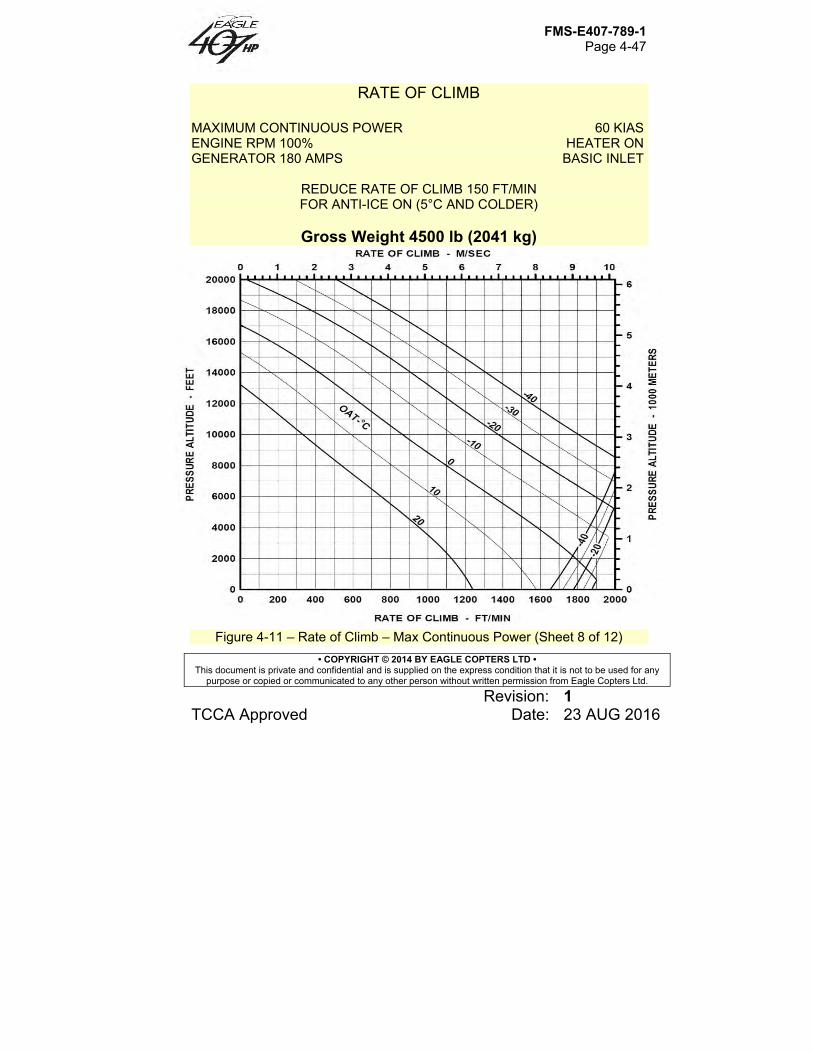
FMS-E407-789-1 Page 4-47
• COPYRIGHT © 2014 BY EAGLE COPTERS LTD • This document is private and confidential and is supplied on the express condition that it is not to be used for any
purpose or copied or communicated to any other person without written permission from Eagle Copters Ltd.
Revision: 1 TCCA Approved Date: 23 AUG 2016
RATE OF CLIMB MAXIMUM CONTINUOUS POWER 60 KIAS ENGINE RPM 100% HEATER ON GENERATOR 180 AMPS BASIC INLET
REDUCE RATE OF CLIMB 150 FT/MIN FOR ANTI-ICE ON (5°C AND COLDER)
Gross Weight 4500 lb (2041 kg)
Figure 4-11 – Rate of Climb – Max Continuous Power (Sheet 8 of 12)
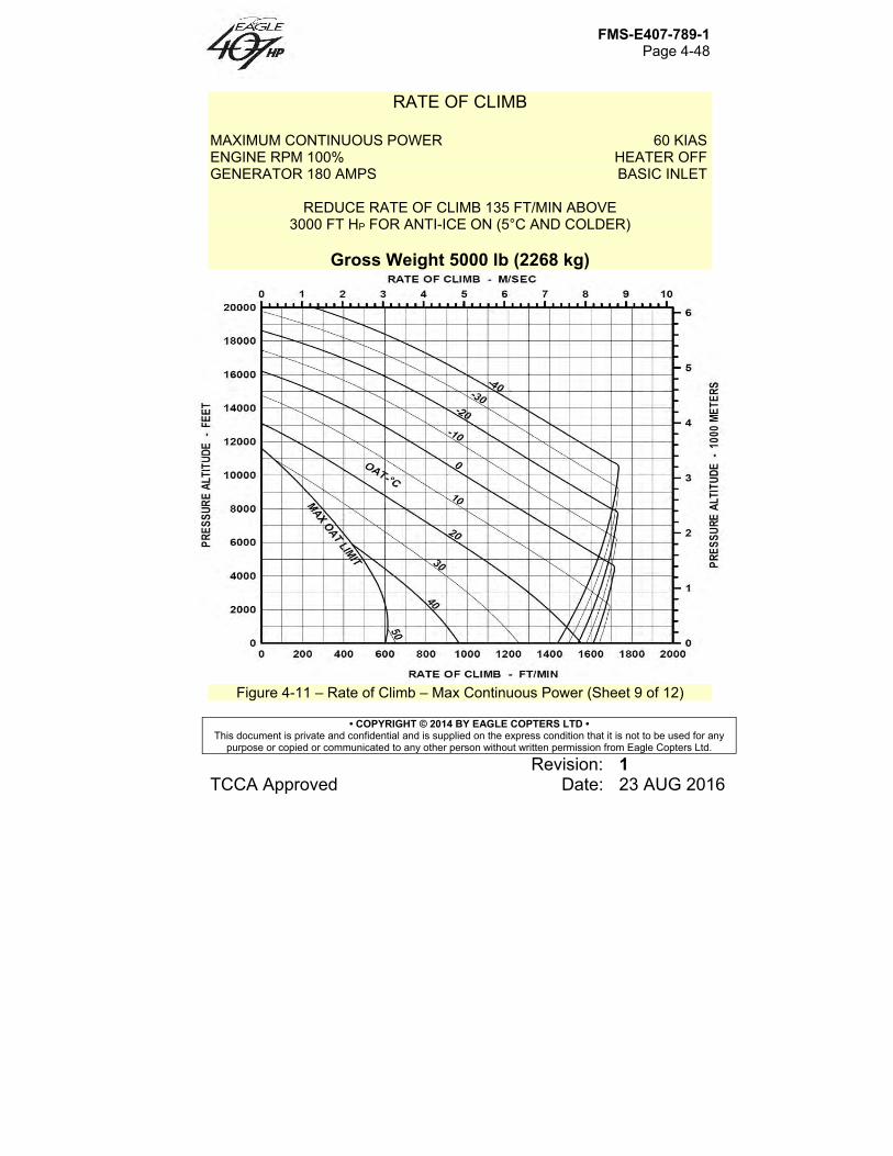
FMS-E407-789-1 Page 4-48
• COPYRIGHT © 2014 BY EAGLE COPTERS LTD • This document is private and confidential and is supplied on the express condition that it is not to be used for any
purpose or copied or communicated to any other person without written permission from Eagle Copters Ltd.
Revision: 1 TCCA Approved Date: 23 AUG 2016
RATE OF CLIMB MAXIMUM CONTINUOUS POWER 60 KIAS ENGINE RPM 100% HEATER OFF GENERATOR 180 AMPS BASIC INLET
REDUCE RATE OF CLIMB 135 FT/MIN ABOVE 3000 FT HP FOR ANTI-ICE ON (5°C AND COLDER)
Gross Weight 5000 lb (2268 kg)
Figure 4-11 – Rate of Climb – Max Continuous Power (Sheet 9 of 12)
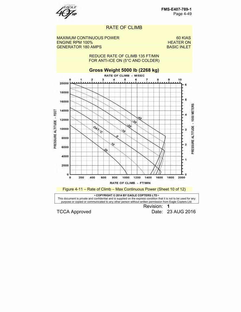
FMS-E407-789-1 Page 4-49
• COPYRIGHT © 2014 BY EAGLE COPTERS LTD • This document is private and confidential and is supplied on the express condition that it is not to be used for any
purpose or copied or communicated to any other person without written permission from Eagle Copters Ltd.
Revision: 1 TCCA Approved Date: 23 AUG 2016
RATE OF CLIMB MAXIMUM CONTINUOUS POWER 60 KIAS ENGINE RPM 100% HEATER ON GENERATOR 180 AMPS BASIC INLET
REDUCE RATE OF CLIMB 135 FT/MIN FOR ANTI-ICE ON (5°C AND COLDER)
Gross Weight 5000 lb (2268 kg)
Figure 4-11 – Rate of Climb – Max Continuous Power (Sheet 10 of 12)
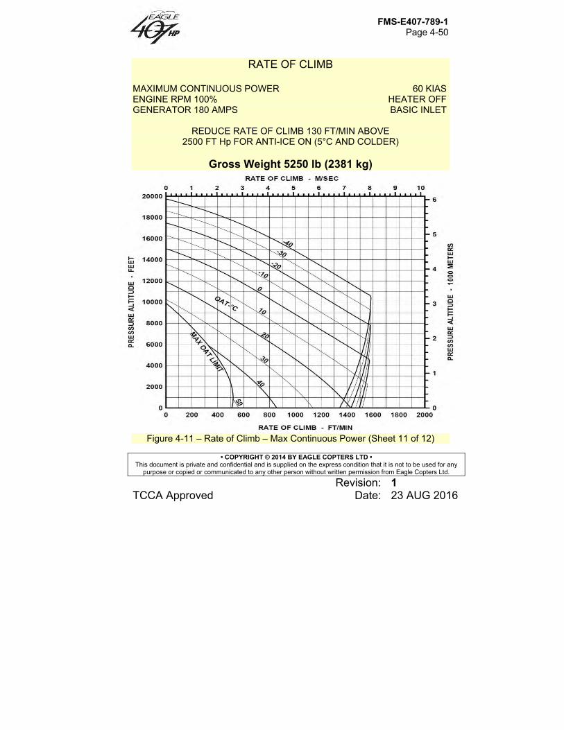
FMS-E407-789-1 Page 4-50
• COPYRIGHT © 2014 BY EAGLE COPTERS LTD • This document is private and confidential and is supplied on the express condition that it is not to be used for any
purpose or copied or communicated to any other person without written permission from Eagle Copters Ltd.
Revision: 1 TCCA Approved Date: 23 AUG 2016
RATE OF CLIMB MAXIMUM CONTINUOUS POWER 60 KIAS ENGINE RPM 100% HEATER OFF GENERATOR 180 AMPS BASIC INLET
REDUCE RATE OF CLIMB 130 FT/MIN ABOVE 2500 FT Hp FOR ANTI-ICE ON (5°C AND COLDER)
Gross Weight 5250 lb (2381 kg)
Figure 4-11 – Rate of Climb – Max Continuous Power (Sheet 11 of 12)
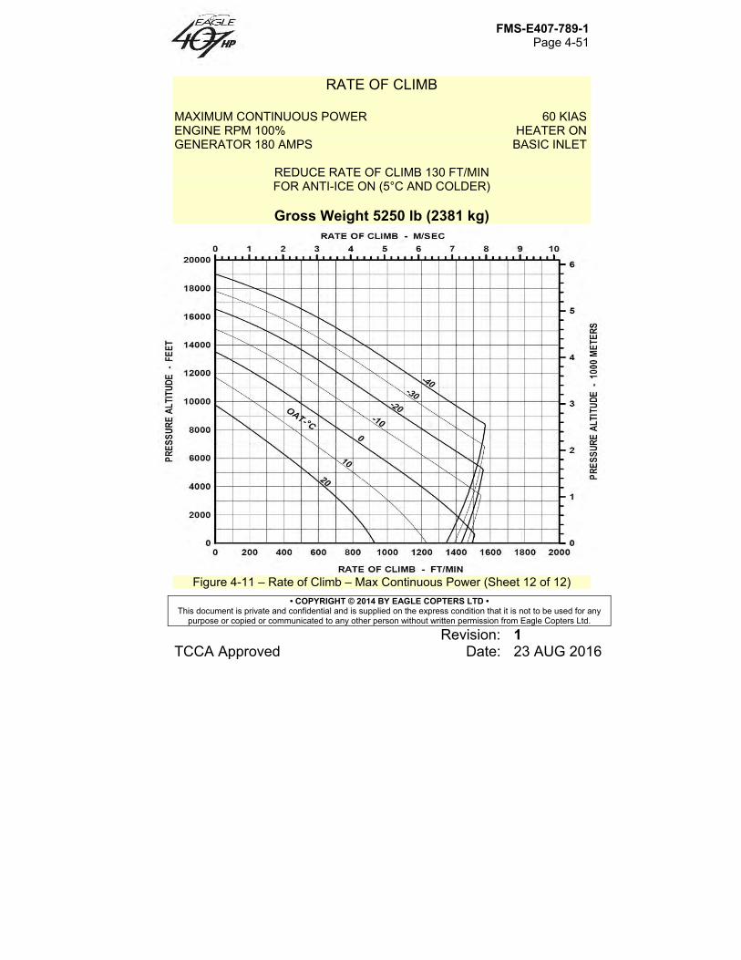
FMS-E407-789-1 Page 4-51
• COPYRIGHT © 2014 BY EAGLE COPTERS LTD • This document is private and confidential and is supplied on the express condition that it is not to be used for any
purpose or copied or communicated to any other person without written permission from Eagle Copters Ltd.
Revision: 1 TCCA Approved Date: 23 AUG 2016
RATE OF CLIMB MAXIMUM CONTINUOUS POWER 60 KIAS ENGINE RPM 100% HEATER ON GENERATOR 180 AMPS BASIC INLET
REDUCE RATE OF CLIMB 130 FT/MIN FOR ANTI-ICE ON (5°C AND COLDER)
Gross Weight 5250 lb (2381 kg)
Figure 4-11 – Rate of Climb – Max Continuous Power (Sheet 12 of 12)
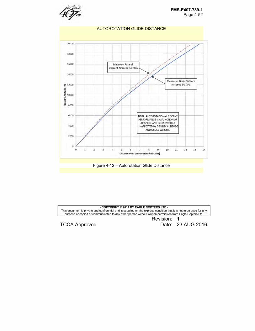
FMS-E407-789-1 Page 4-52
• COPYRIGHT © 2014 BY EAGLE COPTERS LTD • This document is private and confidential and is supplied on the express condition that it is not to be used for any
purpose or copied or communicated to any other person without written permission from Eagle Copters Ltd.
Revision: 1 TCCA Approved Date: 23 AUG 2016
AUTOROTATION GLIDE DISTANCE
Figure 4-12 – Autorotation Glide Distance
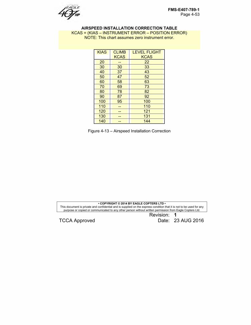
FMS-E407-789-1 Page 4-53
• COPYRIGHT © 2014 BY EAGLE COPTERS LTD • This document is private and confidential and is supplied on the express condition that it is not to be used for any
purpose or copied or communicated to any other person without written permission from Eagle Copters Ltd.
Revision: 1 TCCA Approved Date: 23 AUG 2016
AIRSPEED INSTALLATION CORRECTION TABLE KCAS = (KIAS – INSTRUMENT ERROR – POSITION ERROR)
NOTE: This chart assumes zero instrument error.
KIAS CLIMB KCAS
LEVEL FLIGHT KCAS
20 -- 22 30 30 33 40 37 43 50 47 52 60 58 63 70 69 73 80 78 82 90 87 92
100 95 100 110 -- 110 120 -- 121 130 -- 131 140 -- 144
Figure 4-13 – Airspeed Installation Correction

FMS-E407-789-1 Page 5-1
• COPYRIGHT © 2014 BY EAGLE COPTERS LTD • This document is private and confidential and is supplied on the express condition that it is not to be used for any
purpose or copied or communicated to any other person without written permission from Eagle Copters Ltd.
Revision: 0 Unapproved Date: 10 NOV 2014
Section 5 Weight and Balance Data
Table of Contents
5.1 Introduction ......................................................................................... 5-3 5.2 Empty Weight Center of Gravity ......................................................... 5-3
5.2.A Empty Weight ..................................................................................... 5-3 5.2.B Center of Gravity ................................................................................ 5-3
5.3 Gross Weight Center of Gravity .......................................................... 5-4 5.3.A Useful Loads ....................................................................................... 5-4 5.3.B Center of Gravity ................................................................................ 5-5
5.4 Doors Open or Removed .................................................................... 5-5 5.4.A Door Weights and Moments ............................................................... 5-5 5.4.B Ballast Adjustment .............................................................................. 5-6
5.5 Cockpit and Cabin Loading ................................................................ 5-6 5.5.A Longitudinal Loading .......................................................................... 5-7 5.5.B Most Forward and Most Aft CG .......................................................... 5-7 5.5.C Alternate Loading ............................................................................... 5-8 5.5.D Cabin Floor Loading ........................................................................... 5-8
5.6 Baggage Compartment Loading ......................................................... 5-8 5.7 Fuel Loading ....................................................................................... 5-9 5.8 Sample Loading Problem ................................................................... 5-9
FMS-E407-789-1 Page 5-2
• COPYRIGHT © 2014 BY EAGLE COPTERS LTD • This document is private and confidential and is supplied on the express condition that it is not to be used for any
purpose or copied or communicated to any other person without written permission from Eagle Copters Ltd.
Revision: 0 Unapproved Date: 10 NOV 2014
List of Figures and Tables Figure 5-1 – Fuselage Stations ..................................................................... 5-10 Figure 5-2 – Buttock Lines Inches (Millimeters) ............................................ 5-11 Figure 5-3 – Fuel Center of Gravity .............................................................. 5-12 Table 5-1 – Door Weights and Moments (US) .............................................. 5-13 Table 5-2 – Cabin and Baggage Loading (U.S.) ........................................... 5-14 Table 5-2M – Cabin and Baggage Loading (Metric) ..................................... 5-15 Table 5-3 – Fuel Loading (U.S.) .................................................................... 5-16 Table 5-3M – Fuel Loading (Metric) .............................................................. 5-17 Table 5-4 – Fuel Density Versus Temperature ............................................. 5-18 Table 5-5 – Sample Loading Problem (US) .................................................. 5-19 Table 5-5M – Sample Loading Problem (Metric) .......................................... 5-21 Table 5-6 – Weight and Balance Worksheet (US) ........................................ 5-23 Table 5-6M – Weight and Balance Worksheet (Metric) ................................ 5-24
FMS-E407-789-1 Page 5-3
• COPYRIGHT © 2014 BY EAGLE COPTERS LTD • This document is private and confidential and is supplied on the express condition that it is not to be used for any
purpose or copied or communicated to any other person without written permission from Eagle Copters Ltd.
Revision: 0 Unapproved Date: 10 NOV 2014
Section 5 Weight and Balance Data
5.1 Introduction This section provides loading information and instructions necessary to ensure that flight can be performed within the approved gross weight and center of gravity limitations, as defined in Section 1.
5.2 Empty Weight Center of Gravity
5.2.A Empty Weight The empty weight condition consists of the basic helicopter with required equipment, optional equipment kits, transmission and gearbox oils, hydraulic fluid, unusable fuel, undrainable engine oil and fixed ballast. The empty weight and center of gravity are recorded on the Actual Weight Record, a copy of which should be carried in the helicopter to enable weight and balance computations.
5.2.B Center of Gravity An Empty Weight vs. Center of Gravity chart is provided in ICA-E407-789 Chapter 8 as a guide to simplify computing ballast requirements. This chart was derived from gross weight longitudinal center of gravity limits shown in Section 1, using most forward and most aft useful loads for standard seating and fuel.
FMS-E407-789-1 Page 5-4
• COPYRIGHT © 2014 BY EAGLE COPTERS LTD • This document is private and confidential and is supplied on the express condition that it is not to be used for any
purpose or copied or communicated to any other person without written permission from Eagle Copters Ltd.
Revision: 0 Unapproved Date: 10 NOV 2014
Note
Empty weight center of gravity chart is not valid if helicopter has a non-standard fuel system or seating arrangement.
5.3 Gross Weight Center of Gravity Gross weight condition is empty weight condition plus useful load.
5.3.A Useful Loads Useful load consists of usable fuel, engine oil, crew, passengers, baggage and cargo. Combinations of these items, which have most adverse effect on helicopter center of gravity, are known as most forward and most aft useful loads. Whenever cargo and/or baggage are carried, these useful loads may be different for each flight, and weight and balance must be computed to ensure gross weight and center of gravity will remain within limits throughout flight. Standard most forward and most aft useful loads are combinations of fuel, crew and passenger loading only. These loads, in conjunction with empty weight center of gravity chart, allow passengers only (no baggage or other cargo) to be carried within appropriate weight limitations without computing center of gravity for each flight. If helicopter has a non-standard fuel system or seating arrangement, or is not ballasted in accordance with the Empty Weight Versus Center of Gravity chart in ICA-E407-789, Chapter 8, pilot must determine weight and balance to ensure gross weight and center of gravity will remain within limits throughout each flight.
FMS-E407-789-1 Page 5-5
• COPYRIGHT © 2014 BY EAGLE COPTERS LTD • This document is private and confidential and is supplied on the express condition that it is not to be used for any
purpose or copied or communicated to any other person without written permission from Eagle Copters Ltd.
Revision: 0 Unapproved Date: 10 NOV 2014
5.3.B Center of Gravity It is the responsibility of the pilot to ensure that helicopter is properly loaded to maintain center of gravity throughout each flight within gross weight center of gravity limits shown in Section 1 or appropriate supplement. Gross weight longitudinal and lateral center of gravity can be calculated using Actual Weight Record, diagrams and loading tables in this section, and loading tables in applicable Flight Manual Supplements. When carrying baggage, cargo, or non-standard loads, effects of fuel consumption and addition/deletion of passengers, baggage, or cargo at intermediate points should be checked prior to flight. Significant fuselage stations and buttock lines are shown in Figure 5-1 and Figure 5-2 to aid in weight and balance computations.
5.4 Doors Open or Removed When one or more cabin doors are removed, helicopter may exceed gross weight center of gravity limits during flight. If using the Empty Weight Versus Center of Gravity chart (refer to ICA-E407-789, Chapter 8), a ballast adjustment to offset moment change is necessary (Table 5-1). Otherwise, gross weight center of gravity should be computed for each flight.
5.4.A Door Weights and Moments Following table provides weight and moment adjustments for cabin doors. Sign convention for buttock lines used to compute lateral moments are: 1. Left is negative. 2. Right is positive.
FMS-E407-789-1 Page 5-6
• COPYRIGHT © 2014 BY EAGLE COPTERS LTD • This document is private and confidential and is supplied on the express condition that it is not to be used for any
purpose or copied or communicated to any other person without written permission from Eagle Copters Ltd.
Revision: 0 Unapproved Date: 10 NOV 2014
ACTION MOMENT CHANGE LEFT DOOR RIGHT DOOR Remove Positive (+) Negative (-) Install Negative (-) Positive (+) Example: When removing a left door only, subtract positive weight value and negative moment value shown in table. Net effect on helicopter is a reduction in weight and a shift in lateral CG to right (positive direction).
5.4.B Ballast Adjustment Following check can be made to determine if a ballast adjustment is necessary after doors are removed or installed. 1. For helicopters without ballast or with nose ballast, apply weight and moment changes to most aft useful load condition to determine if an increase in nose ballast is required, or a reduction is allowed. 2. For helicopters with tail ballast, apply weight and moment changes to most forward useful load condition to determine if a reduction in tail ballast is allowed, or an increase is required.
Note
Ballast changes are performed by maintenance personnel. After any ballast change, Actual Weight Record must be revised to show new empty weight condition.
5.5 Cockpit and Cabin Loading Loading tables (Table 5-2 and Table 5-2M) provide weights and moments for each passenger location, litter patient, and baggage compartment in both U.S. and metric units.
FMS-E407-789-1 Page 5-7
• COPYRIGHT © 2014 BY EAGLE COPTERS LTD • This document is private and confidential and is supplied on the express condition that it is not to be used for any
purpose or copied or communicated to any other person without written permission from Eagle Copters Ltd.
Revision: 0 Unapproved Date: 10 NOV 2014
To find moments for weights in excess of those shown on tables, multiply weight by fuselage station at which center of gravity of the object is located. An alternate method is to calculate amount of weight in excess of maximum weight listed on table, then read moment for this excess weight from table and add it to moment for maximum weight shown on table. This will give desired moment for the object.
5.5.A Longitudinal Loading 1. A minimum weight of 170 pounds (77.1 kg) is required in cockpit at fuselage station 65.0 when the empty weight center of gravity chart is used. 2. Passenger seating is unrestricted. 3. Cargo loading is restricted only by floor load limit. Refer to Section 1.
5.5.B Most Forward and Most Aft CG When using empty weight center of gravity chart, following combinations of crew, fuel and passenger loading will have most extreme effects on longitudinal center of gravity, assuming standard weights for all crew and passengers. 1. Most forward CG will occur with forward and mid seats occupied and fuel quantity of 74.8 gallons (283.0 L). 2. Most aft CG will occur with one forward seat occupied (pilot) and fuel quantity of 28.4 gallons (107.5 L). Since center of gravity of aft passengers is on aft limit, weight of passengers is not included in most aft useful load. However when most aft center of gravity of a configuration is forward of aft limit, addition of aft passengers will shift center of gravity further aft, and should be included in computation.
FMS-E407-789-1 Page 5-8
• COPYRIGHT © 2014 BY EAGLE COPTERS LTD • This document is private and confidential and is supplied on the express condition that it is not to be used for any
purpose or copied or communicated to any other person without written permission from Eagle Copters Ltd.
Revision: 0 Unapproved Date: 10 NOV 2014
5.5.C Alternate Loading Gross weight center of gravity chart must be used to determine cabin loading requirements under following conditions: 1. Whenever cargo and/or baggage are carried. 2. When actual passenger weights are used. 3. When seating arrangement and/or fuel system are non-standard. 4. When performing specialty missions, such as hoisting or rappelling.
5.5.D Cabin Floor Loading Cabin floor is structurally designed for 75 pounds per square foot (3.7 kg per 100 cm2).
5.6 Baggage Compartment Loading When weight is loaded into baggage compartment, the pilot is required to compute weight and balance, regardless of passenger loading. Baggage compartment is structurally designed for 86 pounds per square foot (4.2 kg per 100 cm2) for a total weight of 250 pounds (113.4 kg). Loading of baggage compartment should be from front to rear. Load shall be secured to tie-down fittings if shifting of load in flight could result in structural damage to baggage compartment or in gross weight center of gravity being exceeded. If load is not secured, center of gravity must be computed with load in most adverse position.
FMS-E407-789-1 Page 5-9
• COPYRIGHT © 2014 BY EAGLE COPTERS LTD • This document is private and confidential and is supplied on the express condition that it is not to be used for any
purpose or copied or communicated to any other person without written permission from Eagle Copters Ltd.
Revision: 0 Unapproved Date: 10 NOV 2014
5.7 Fuel Loading Longitudinal center of gravity of fuel shifts as it is consumed (Figure 5-3). Extreme effects of fuel consumption on helicopter center of gravity for standard fuel system are as follows: 1. Critical fuel for computing most forward useful load is 74.8 gallons (283.0 L). 2. Critical fuel for computing most aft useful load is 28.4 gallons (107.5 L). Fuel loading tables (Table 5-3 and Table 5-3M) list usable fuel quantities, weight and moments in both U.S. and metric units. Fuel density versus temperature (Table 5-4), is provided to calculate fuel weight variation for equivalent volumes of fuel caused by a change in temperature. For example weight of 127.8 gallons (full fuel) of JP-5 at -40°F is 913.8 pounds (414.5 kg) versus 869.0 pounds (394.1 kg) shown on Fuel loading chart (Table 5-3 and Table 5-3M).
5.8 Sample Loading Problem A sample loading problem showing derivation of critical gross weights and center of gravity locations for a typical mission is presented in U.S. and metric units (Table 5-5 and Table 5-5M). Method shown derives a gross weight with zero fuel for each load condition to be checked, then adds appropriate fuel weight and moment read directly from fuel loading table. Center of gravity for each condition is calculated by dividing total moment by total weight. Forms have been provided (Table 5-6 and Table 5-6M) in both U.S. and metric units, to aid in computing critical load conditions for a flight.
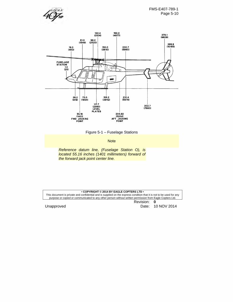
FMS-E407-789-1 Page 5-10
• COPYRIGHT © 2014 BY EAGLE COPTERS LTD • This document is private and confidential and is supplied on the express condition that it is not to be used for any
purpose or copied or communicated to any other person without written permission from Eagle Copters Ltd.
Revision: 0 Unapproved Date: 10 NOV 2014
Figure 5-1 – Fuselage Stations
Note
Reference datum line, (Fuselage Station O), is located 55.16 inches (1401 millimeters) forward of the forward jack point center line.
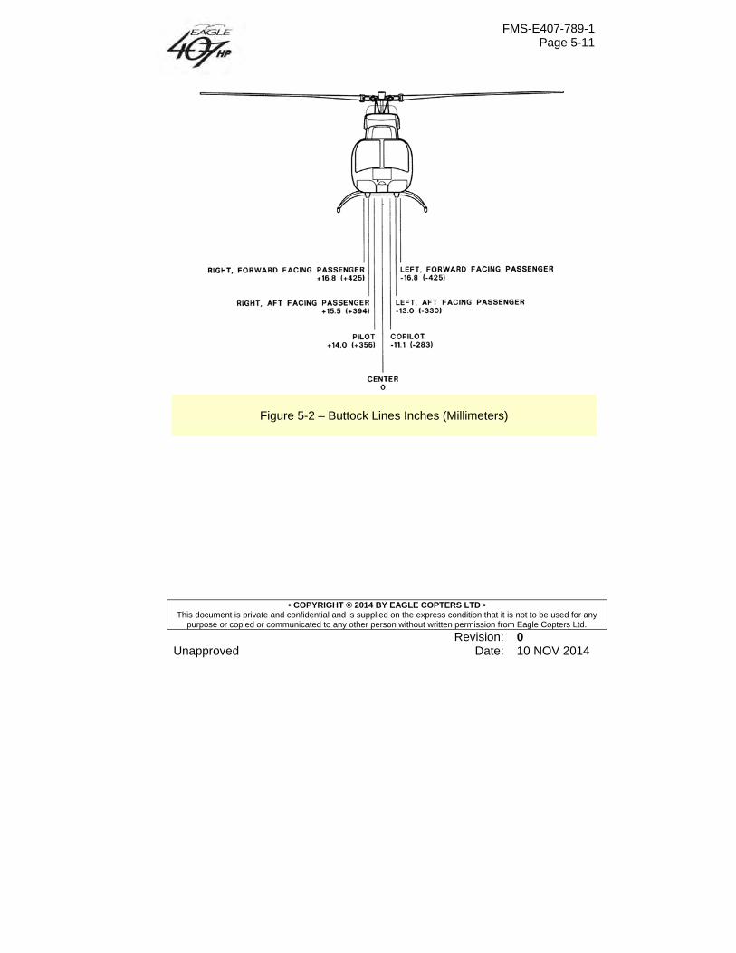
FMS-E407-789-1 Page 5-11
• COPYRIGHT © 2014 BY EAGLE COPTERS LTD • This document is private and confidential and is supplied on the express condition that it is not to be used for any
purpose or copied or communicated to any other person without written permission from Eagle Copters Ltd.
Revision: 0 Unapproved Date: 10 NOV 2014
Figure 5-2 – Buttock Lines Inches (Millimeters)
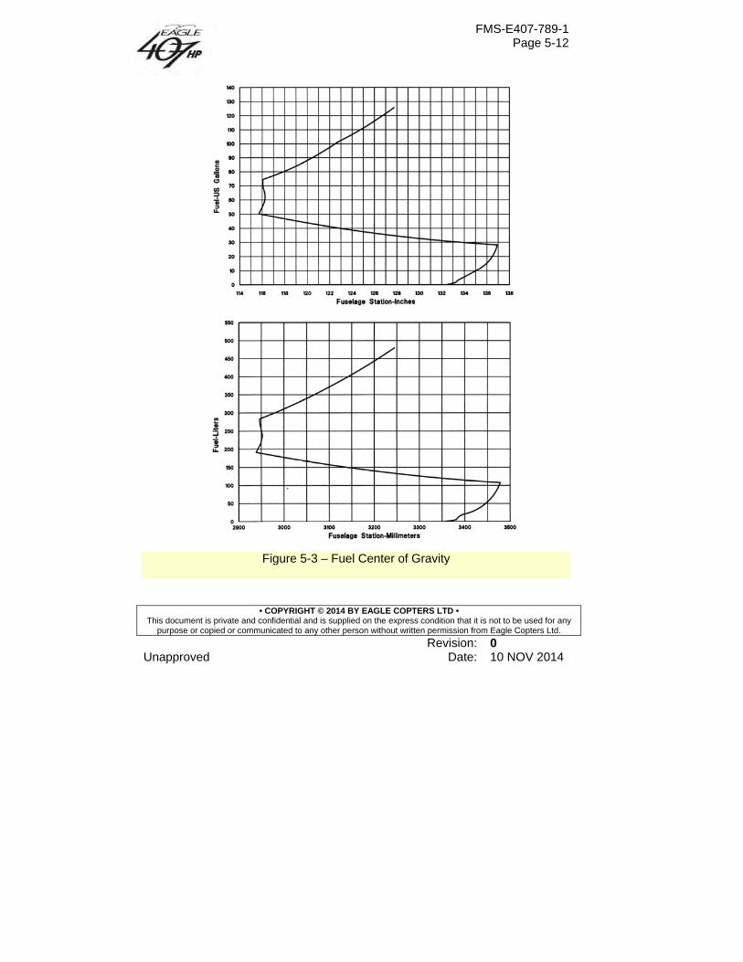
FMS-E407-789-1 Page 5-12
• COPYRIGHT © 2014 BY EAGLE COPTERS LTD • This document is private and confidential and is supplied on the express condition that it is not to be used for any
purpose or copied or communicated to any other person without written permission from Eagle Copters Ltd.
Revision: 0 Unapproved Date: 10 NOV 2014
Figure 5-3 – Fuel Center of Gravity
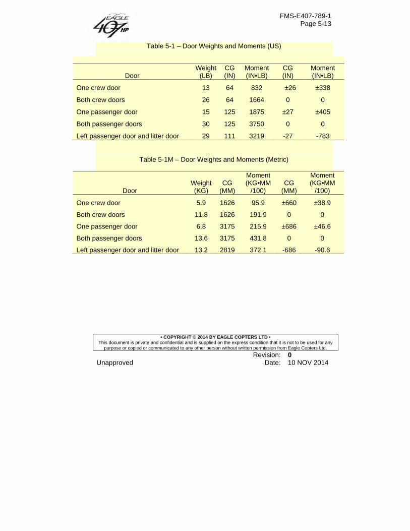
FMS-E407-789-1 Page 5-13
• COPYRIGHT © 2014 BY EAGLE COPTERS LTD • This document is private and confidential and is supplied on the express condition that it is not to be used for any
purpose or copied or communicated to any other person without written permission from Eagle Copters Ltd.
Revision: 0 Unapproved Date: 10 NOV 2014
Table 5-1 – Door Weights and Moments (US)
Door Weight
(LB) CG (IN)
Moment (IN•LB)
CG (IN)
Moment (IN•LB)
One crew door 13 64 832 �±26 ±338
Both crew doors 26 64 1664 0 0
One passenger door 15 125 1875 ±27 ±405
Both passenger doors 30 125 3750 0 0
Left passenger door and litter door 29 111 3219 -27 -783
Table 5-1M – Door Weights and Moments (Metric)
Door Weight (KG)
CG (MM)
Moment (KG•MM
/100) CG
(MM)
Moment (KG•MM
/100)
One crew door 5.9 1626 95.9 ±660 ±38.9
Both crew doors 11.8 1626 191.9 0 0
One passenger door 6.8 3175 215.9 ±686 ±46.6
Both passenger doors 13.6 3175 431.8 0 0
Left passenger door and litter door 13.2 2819 372.1 -686 -90.6
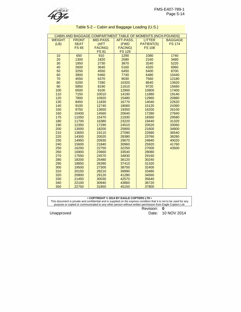
FMS-E407-789-1 Page 5-14
• COPYRIGHT © 2014 BY EAGLE COPTERS LTD • This document is private and confidential and is supplied on the express condition that it is not to be used for any
purpose or copied or communicated to any other person without written permission from Eagle Copters Ltd.
Revision: 0 Unapproved Date: 10 NOV 2014
Table 5-2 – Cabin and Baggage Loading (U.S.)
CABIN AND BAGGAGE COMPARTMENT TABLE OF MOMENTS (INCH-POUNDS) WEIGHT
(LB) FRONT SEAT FS 65
MID-PASS. (AFT
FACING) FS 91
AFT-PASS. (FWD
FACING) FS 129
LITTER PATIENT(S)
FS 108
BAGGAGE FS 174
10 650 910 1290 1080 1740 20 1300 1820 2580 2160 3480 30 1950 2730 3870 3240 5220 40 2600 3640 5160 4320 6960 50 3250 4550 6450 5400 8700 60 3900 5460 7740 6480 10440 70 4550 6370 9030 7560 12180 80 5200 7280 10320 8640 13920 90 5850 8190 11610 9720 15660 100 6500 9100 12900 10800 17400 110 7150 10010 14190 11880 19140 120 7800 10920 15480 12960 20880 130 8450 11830 16770 14040 22620 140 9100 12740 18060 15120 24360 150 9750 13650 19350 16200 26100 160 10400 14560 20640 17280 27840 170 11050 15470 21930 18360 29580 180 11700 16380 23220 19440 31320 190 12350 17290 24510 20520 33060 200 13000 18200 25800 21600 34800 210 13650 19110 27090 22680 36540 220 14300 20020 28380 23760 38280 230 14950 20930 29670 24840 40020 240 15600 21840 30960 25920 41760 250 16250 22750 32250 27000 43500 260 16900 23660 33540 28080 270 17550 24570 34830 29160 280 18200 25480 36120 30240 290 18850 26390 37410 31320 300 19500 27300 38700 32400 310 20150 28210 39990 33480 320 20800 29120 41280 34560 330 21450 30030 42570 35640 340 22100 30940 43860 36720 350 22750 31850 45150 37800
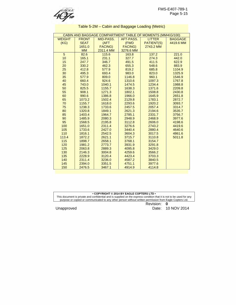
FMS-E407-789-1 Page 5-15
• COPYRIGHT © 2014 BY EAGLE COPTERS LTD • This document is private and confidential and is supplied on the express condition that it is not to be used for any
purpose or copied or communicated to any other person without written permission from Eagle Copters Ltd.
Revision: 0 Unapproved Date: 10 NOV 2014
Table 5-2M – Cabin and Baggage Loading (Metric)
CABIN AND BAGGAGE COMPARTMENT TABLE OF MOMENTS (MM•KG/100) WEIGHT
(KG) FRONT SEAT 1651.0
MM
MID-PASS. (AFT
FACING) 2311.4 MM
AFT-PASS. (FWD
FACING) 3276.6 MM
LITTER PATIENT(S) 2743.2 MM
BAGGAGE 4419.6 MM
5 82.6 115.6 163.8 137.2 221.0 10 165.1 231.1 327.7 274.3 442.0 15 247.7 346.7 491.5 411.5 622.9 20 330.2 462.3 655.3 548.6 883.9 25 412.8 577.9 819.2 685.8 1104.9 30 495.3 693.4 983.0 823.0 1325.9 35 577.9 809.0 1146.8 960.1 1546.9 40 660.4 924.6 1310.6 1097.3 1767.8 45 743.0 1040.1 1474.5 1234.4 1988.8 50 825.5 1155.7 1638.3 1371.6 2209.8 55 908.1 1271.3 1802.1 1508.8 2430.8 60 990.6 1386.8 1966.0 1645.9 2651.8 65 1073.2 1502.4 2129.8 1783.1 2872.7 70 1155.7 1618.0 2293.6 1920.2 3093.7 75 1238.3 1733.6 2457.5 2057.4 3314.7 80 1320.8 1849.1 2621.3 2194.6 3535.7 85 1403.4 1964.7 2785.1 2331.7 3756.7 90 1485.9 2080.3 2948.9 2468.9 3977.6 95 1568.5 2195.8 3112.8 2606.0 4198.6 100 1651.0 2311.4 3276.6 2743.2 4419.6 105 1733.6 2427.0 3440.4 2880.4 4640.6 110 1816.1 2542.5 3604.3 3017.5 4861.6
113.4 1872.2 2621.1 3715.7 3110.8 5011.8 115 1898.7 2658.1 3768.1 3154.7 120 1981.2 2773.7 3931.9 3291.8 125 2063.8 2889.3 4095.8 3429.0 130 2146.3 3004.8 4259.6 3566.2 135 2228.9 3120.4 4423.4 3703.3 140 2311.4 3236.0 4587.2 3840.5 145 2394.0 3351.5 4751.1 3977.6 150 2476.5 3467.1 4914.9 4114.8
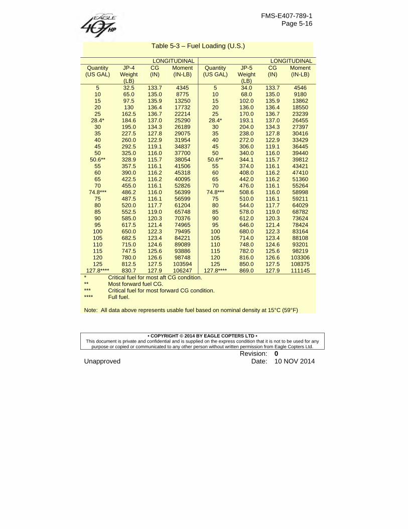
FMS-E407-789-1 Page 5-16
• COPYRIGHT © 2014 BY EAGLE COPTERS LTD • This document is private and confidential and is supplied on the express condition that it is not to be used for any
purpose or copied or communicated to any other person without written permission from Eagle Copters Ltd.
Revision: 0 Unapproved Date: 10 NOV 2014
Table 5-3 – Fuel Loading (U.S.)
LONGITUDINAL LONGITUDINAL Quantity
(US GAL) JP-4
Weight (LB)
CG (IN)
Moment (IN-LB)
Quantity (US GAL)
JP-5 Weight
(LB)
CG (IN)
Moment (IN-LB)
5 32.5 133.7 4345 5 34.0 133.7 4546 10 65.0 135.0 8775 10 68.0 135.0 9180 15 97.5 135.9 13250 15 102.0 135.9 13862 20 130 136.4 17732 20 136.0 136.4 18550 25 162.5 136.7 22214 25 170.0 136.7 23239
28.4* 184.6 137.0 25290 28.4* 193.1 137.0 26455 30 195.0 134.3 26189 30 204.0 134.3 27397 35 227.5 127.8 29075 35 238.0 127.8 30416 40 260.0 122.9 31954 40 272.0 122.9 33429 45 292.5 119.1 34837 45 306.0 119.1 36445 50 325.0 116.0 37700 50 340.0 116.0 39440
50.6** 328.9 115.7 38054 50.6** 344.1 115.7 39812 55 357.5 116.1 41506 55 374.0 116.1 43421 60 390.0 116.2 45318 60 408.0 116.2 47410 65 422.5 116.2 40095 65 442.0 116.2 51360 70 455.0 116.1 52826 70 476.0 116.1 55264
74.8*** 486.2 116.0 56399 74.8*** 508.6 116.0 58998 75 487.5 116.1 56599 75 510.0 116.1 59211 80 520.0 117.7 61204 80 544.0 117.7 64029 85 552.5 119.0 65748 85 578.0 119.0 68782 90 585.0 120.3 70376 90 612.0 120.3 73624 95 617.5 121.4 74965 95 646.0 121.4 78424 100 650.0 122.3 79495 100 680.0 122.3 83164 105 682.5 123.4 84221 105 714.0 123.4 88108 110 715.0 124.6 89089 110 748.0 124.6 93201 115 747.5 125.6 93886 115 782.0 125.6 98219 120 780.0 126.6 98748 120 816.0 126.6 103306 125 812.5 127.5 103594 125 850.0 127.5 108375
127.8**** 830.7 127.9 106247 127.8**** 869.0 127.9 111145 * Critical fuel for most aft CG condition. ** Most forward fuel CG. *** Critical fuel for most forward CG condition. **** Full fuel. Note: All data above represents usable fuel based on nominal density at 15°C (59°F)
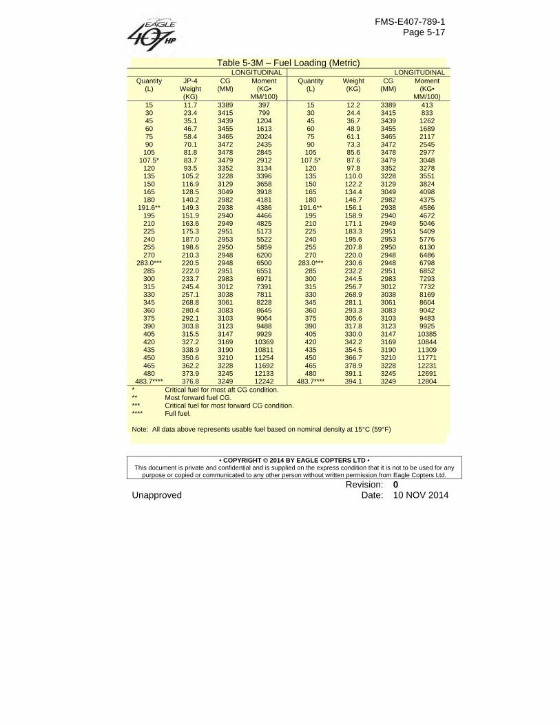
FMS-E407-789-1 Page 5-17
• COPYRIGHT © 2014 BY EAGLE COPTERS LTD • This document is private and confidential and is supplied on the express condition that it is not to be used for any
purpose or copied or communicated to any other person without written permission from Eagle Copters Ltd.
Revision: 0 Unapproved Date: 10 NOV 2014
Table 5-3M – Fuel Loading (Metric) LONGITUDINAL LONGITUDINAL
Quantity (L)
JP-4 Weight (KG)
CG (MM)
Moment (KG•
MM/100)
Quantity (L)
Weight (KG)
CG (MM)
Moment (KG•
MM/100) 15 11.7 3389 397 15 12.2 3389 413 30 23.4 3415 799 30 24.4 3415 833 45 35.1 3439 1204 45 36.7 3439 1262 60 46.7 3455 1613 60 48.9 3455 1689 75 58.4 3465 2024 75 61.1 3465 2117 90 70.1 3472 2435 90 73.3 3472 2545
105 81.8 3478 2845 105 85.6 3478 2977 107.5* 83.7 3479 2912 107.5* 87.6 3479 3048
120 93.5 3352 3134 120 97.8 3352 3278 135 105.2 3228 3396 135 110.0 3228 3551 150 116.9 3129 3658 150 122.2 3129 3824 165 128.5 3049 3918 165 134.4 3049 4098 180 140.2 2982 4181 180 146.7 2982 4375
191.6** 149.3 2938 4386 191.6** 156.1 2938 4586 195 151.9 2940 4466 195 158.9 2940 4672 210 163.6 2949 4825 210 171.1 2949 5046 225 175.3 2951 5173 225 183.3 2951 5409 240 187.0 2953 5522 240 195.6 2953 5776 255 198.6 2950 5859 255 207.8 2950 6130 270 210.3 2948 6200 270 220.0 2948 6486
283.0*** 220.5 2948 6500 283.0*** 230.6 2948 6798 285 222.0 2951 6551 285 232.2 2951 6852 300 233.7 2983 6971 300 244.5 2983 7293 315 245.4 3012 7391 315 256.7 3012 7732 330 257.1 3038 7811 330 268.9 3038 8169 345 268.8 3061 8228 345 281.1 3061 8604 360 280.4 3083 8645 360 293.3 3083 9042 375 292.1 3103 9064 375 305.6 3103 9483 390 303.8 3123 9488 390 317.8 3123 9925 405 315.5 3147 9929 405 330.0 3147 10385 420 327.2 3169 10369 420 342.2 3169 10844 435 338.9 3190 10811 435 354.5 3190 11309 450 350.6 3210 11254 450 366.7 3210 11771 465 362.2 3228 11692 465 378.9 3228 12231 480 373.9 3245 12133 480 391.1 3245 12691
483.7**** 376.8 3249 12242 483.7**** 394.1 3249 12804 * Critical fuel for most aft CG condition. ** Most forward fuel CG. *** Critical fuel for most forward CG condition. **** Full fuel. Note: All data above represents usable fuel based on nominal density at 15°C (59°F)

FMS-E407-789-1 Page 5-18
• COPYRIGHT © 2014 BY EAGLE COPTERS LTD • This document is private and confidential and is supplied on the express condition that it is not to be used for any
purpose or copied or communicated to any other person without written permission from Eagle Copters Ltd.
Revision: 0 Unapproved Date: 10 NOV 2014
Table 5-4 – Fuel Density Versus Temperature
TEMPERATURE (°F)
DENSITY LB/GAL
JP-4
DENSITYLB/GAL
JP-5
TEMPERATURE(°C)
DENSITY KG/L JP-4
DENSITYKG/L JP-5
120 6.27 6.59 40 0.759 0.797 100 6.35 6.66 30 0.767 0.805 80 6.42 6.73 20 0.775 0.812 60* 6.50 6.80 15.56* 0.779 0.815 40 6.58 6.87 10 0.784 0.820 20 6.65 6.94 0 0.792 0.827 0 6.73 7.01 -10 0.800 0.835
-20 6.80 7.08 -20 0.808 0.842 -40 6.88 7.15 -30 0.816 0.850
-40 0.824 0.857 * Standard density, used to derive fuel burn curves.
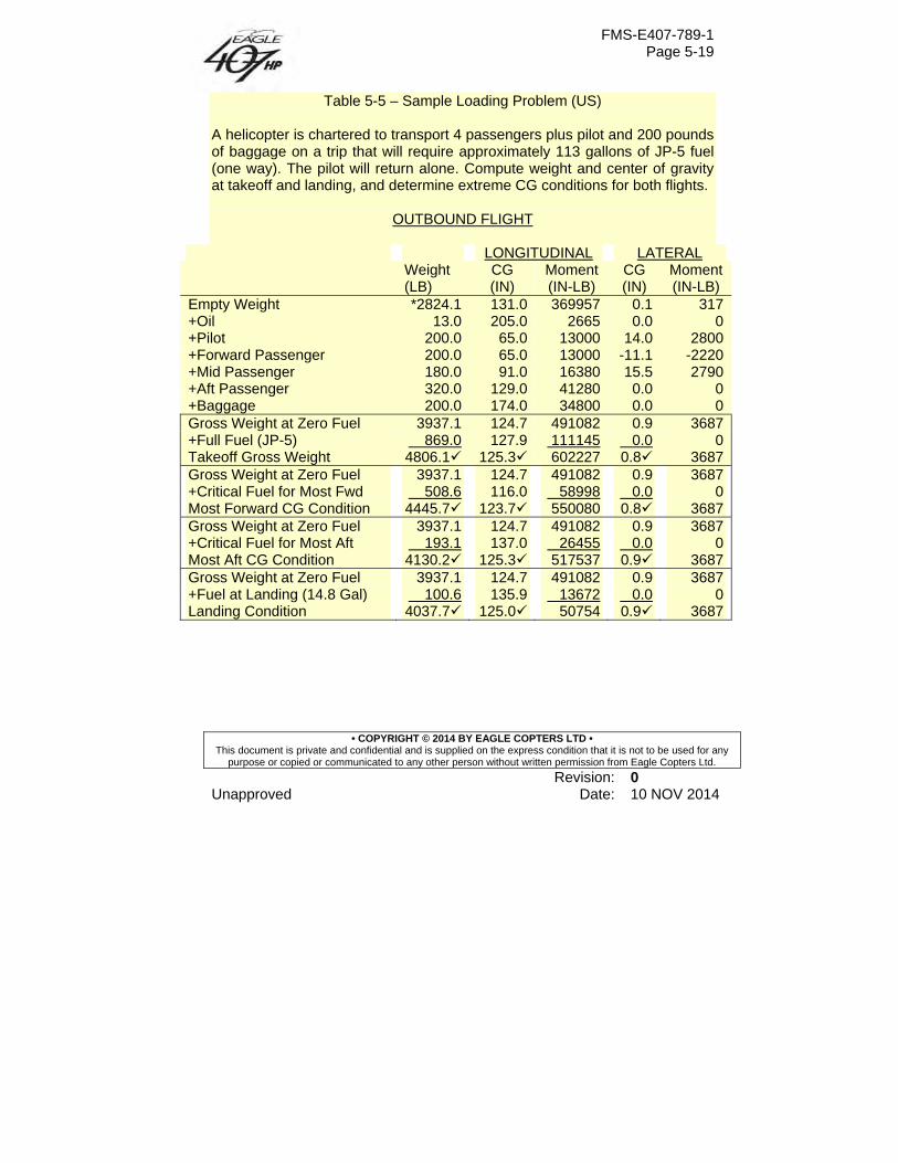
FMS-E407-789-1 Page 5-19
• COPYRIGHT © 2014 BY EAGLE COPTERS LTD • This document is private and confidential and is supplied on the express condition that it is not to be used for any
purpose or copied or communicated to any other person without written permission from Eagle Copters Ltd.
Revision: 0 Unapproved Date: 10 NOV 2014
Table 5-5 – Sample Loading Problem (US) A helicopter is chartered to transport 4 passengers plus pilot and 200 pounds of baggage on a trip that will require approximately 113 gallons of JP-5 fuel (one way). The pilot will return alone. Compute weight and center of gravity at takeoff and landing, and determine extreme CG conditions for both flights.
OUTBOUND FLIGHT
LONGITUDINAL LATERAL Weight
(LB) CG (IN)
Moment (IN-LB)
CG (IN)
Moment (IN-LB)
Empty Weight *2824.1 131.0 369957 0.1 317+Oil 13.0 205.0 2665 0.0 0+Pilot 200.0 65.0 13000 14.0 2800+Forward Passenger 200.0 65.0 13000 -11.1 -2220+Mid Passenger 180.0 91.0 16380 15.5 2790+Aft Passenger 320.0 129.0 41280 0.0 0+Baggage 200.0 174.0 34800 0.0 0Gross Weight at Zero Fuel 3937.1 124.7 491082 0.9 3687+Full Fuel (JP-5) 869.0 127.9 111145 0.0 0Takeoff Gross Weight 4806.1 125.3 602227 0.8 3687Gross Weight at Zero Fuel 3937.1 124.7 491082 0.9 3687+Critical Fuel for Most Fwd 508.6 116.0 58998 0.0 0Most Forward CG Condition 4445.7 123.7 550080 0.8 3687Gross Weight at Zero Fuel 3937.1 124.7 491082 0.9 3687+Critical Fuel for Most Aft 193.1 137.0 26455 0.0 0Most Aft CG Condition 4130.2 125.3 517537 0.9 3687Gross Weight at Zero Fuel 3937.1 124.7 491082 0.9 3687+Fuel at Landing (14.8 Gal) 100.6 135.9 13672 0.0 0Landing Condition 4037.7 125.0 50754 0.9 3687
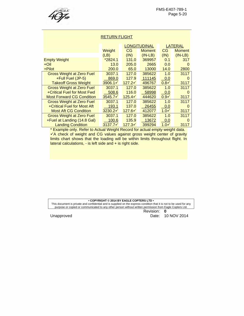
FMS-E407-789-1 Page 5-20
• COPYRIGHT © 2014 BY EAGLE COPTERS LTD • This document is private and confidential and is supplied on the express condition that it is not to be used for any
purpose or copied or communicated to any other person without written permission from Eagle Copters Ltd.
Revision: 0 Unapproved Date: 10 NOV 2014
RETURN FLIGHT
LONGITUDINAL LATERAL Weight
(LB) CG (IN)
Moment (IN-LB)
CG (IN)
Moment (IN-LB)
Empty Weight *2824.1 131.0 369957 0.1 317 +Oil 13.0 205.0 2665 0.0 0 +Pilot 200.0 65.0 13000 14.0 2800
Gross Weight at Zero Fuel 3037.1 127.0 385622 1.0 3117 +Full Fuel (JP-5) 869.0 127.9 111145 0.0 0
Takeoff Gross Weight 3906.1 127.2 496767 0.8 3117 Gross Weight at Zero Fuel 3037.1 127.0 385622 1.0 3117 +Critical Fuel for Most Fwd 508.6 116.0 58998 0.0 0 Most Forward CG Condition 3545.7 125.4 444620 0.9 3117 Gross Weight at Zero Fuel 3037.1 127.0 385622 1.0 3117 +Critical Fuel for Most Aft 193.1 137.0 26455 0.0 0
Most Aft CG Condition 3230.2 127.6 412077 1.0 3117 Gross Weight at Zero Fuel 3037.1 127.0 385622 1.0 3117 +Fuel at Landing (14.8 Gal) 100.6 135.9 13672 0.0 0
Landing Condition 3137.7 127.3 399294 1.0 3117 * Example only. Refer to Actual Weight Record for actual empty weight data. A check of weight and CG values against gross weight center of gravity limits chart shows that the loading will be within limits throughout flight. In lateral calculations, - is left side and + is right side.
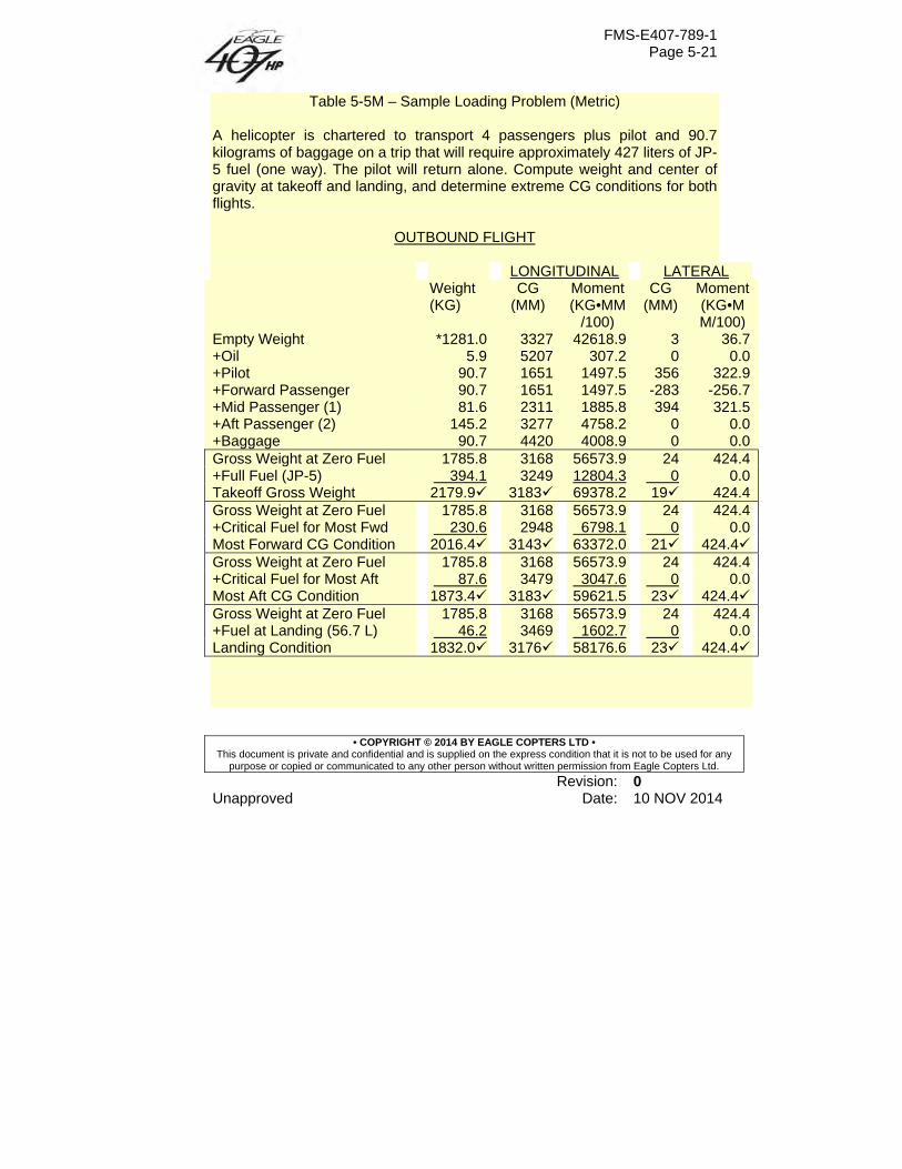
FMS-E407-789-1 Page 5-21
• COPYRIGHT © 2014 BY EAGLE COPTERS LTD • This document is private and confidential and is supplied on the express condition that it is not to be used for any
purpose or copied or communicated to any other person without written permission from Eagle Copters Ltd.
Revision: 0 Unapproved Date: 10 NOV 2014
Table 5-5M – Sample Loading Problem (Metric) A helicopter is chartered to transport 4 passengers plus pilot and 90.7 kilograms of baggage on a trip that will require approximately 427 liters of JP-5 fuel (one way). The pilot will return alone. Compute weight and center of gravity at takeoff and landing, and determine extreme CG conditions for both flights.
OUTBOUND FLIGHT LONGITUDINAL LATERAL Weight
(KG) CG
(MM) Moment (KG•MM
/100)
CG (MM)
Moment (KG•MM/100)
Empty Weight *1281.0 3327 42618.9 3 36.7+Oil 5.9 5207 307.2 0 0.0+Pilot 90.7 1651 1497.5 356 322.9+Forward Passenger 90.7 1651 1497.5 -283 -256.7+Mid Passenger (1) 81.6 2311 1885.8 394 321.5+Aft Passenger (2) 145.2 3277 4758.2 0 0.0+Baggage 90.7 4420 4008.9 0 0.0Gross Weight at Zero Fuel 1785.8 3168 56573.9 24 424.4+Full Fuel (JP-5) 394.1 3249 12804.3 0 0.0Takeoff Gross Weight 2179.9 3183 69378.2 19 424.4Gross Weight at Zero Fuel 1785.8 3168 56573.9 24 424.4+Critical Fuel for Most Fwd 230.6 2948 6798.1 0 0.0Most Forward CG Condition 2016.4 3143 63372.0 21 424.4Gross Weight at Zero Fuel 1785.8 3168 56573.9 24 424.4+Critical Fuel for Most Aft 87.6 3479 3047.6 0 0.0Most Aft CG Condition 1873.4 3183 59621.5 23 424.4Gross Weight at Zero Fuel 1785.8 3168 56573.9 24 424.4+Fuel at Landing (56.7 L) 46.2 3469 1602.7 0 0.0Landing Condition 1832.0 3176 58176.6 23 424.4
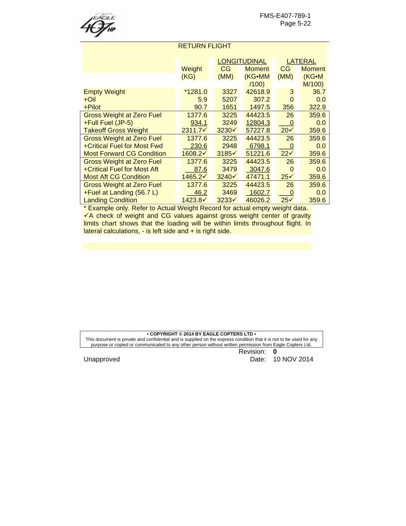
FMS-E407-789-1 Page 5-22
• COPYRIGHT © 2014 BY EAGLE COPTERS LTD • This document is private and confidential and is supplied on the express condition that it is not to be used for any
purpose or copied or communicated to any other person without written permission from Eagle Copters Ltd.
Revision: 0 Unapproved Date: 10 NOV 2014
RETURN FLIGHT
LONGITUDINAL LATERAL Weight
(KG) CG
(MM) Moment (KG•MM
/100)
CG (MM)
Moment (KG•MM/100)
Empty Weight *1281.0 3327 42618.9 3 36.7 +Oil 5.9 5207 307.2 0 0.0 +Pilot 90.7 1651 1497.5 356 322.9 Gross Weight at Zero Fuel 1377.6 3225 44423.5 26 359.6 +Full Fuel (JP-5) 934.1 3249 12804.3 0 0.0 Takeoff Gross Weight 2311.7 3230 57227.8 20 359.6 Gross Weight at Zero Fuel 1377.6 3225 44423.5 26 359.6 +Critical Fuel for Most Fwd 230.6 2948 6798.1 0 0.0 Most Forward CG Condition 1608.2 3185 51221.6 22 359.6 Gross Weight at Zero Fuel 1377.6 3225 44423.5 26 359.6 +Critical Fuel for Most Aft 87.6 3479 3047.6 0 0.0 Most Aft CG Condition 1465.2 3240 47471.1 25 359.6 Gross Weight at Zero Fuel 1377.6 3225 44423.5 26 359.6 +Fuel at Landing (56.7 L) 46.2 3469 1602.7 0 0.0 Landing Condition 1423.8 3233 46026.2 25 359.6 * Example only. Refer to Actual Weight Record for actual empty weight data. A check of weight and CG values against gross weight center of gravity limits chart shows that the loading will be within limits throughout flight. In lateral calculations, - is left side and + is right side.
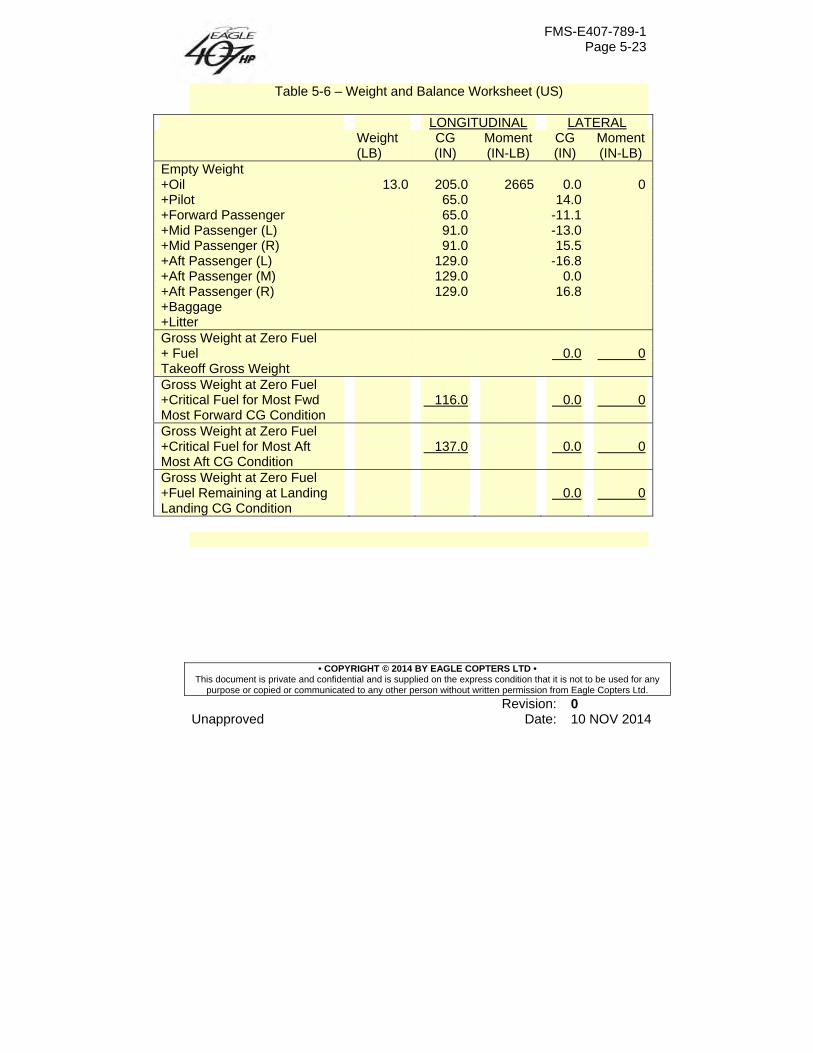
FMS-E407-789-1 Page 5-23
• COPYRIGHT © 2014 BY EAGLE COPTERS LTD • This document is private and confidential and is supplied on the express condition that it is not to be used for any
purpose or copied or communicated to any other person without written permission from Eagle Copters Ltd.
Revision: 0 Unapproved Date: 10 NOV 2014
Table 5-6 – Weight and Balance Worksheet (US)
LONGITUDINAL LATERAL Weight
(LB) CG (IN)
Moment (IN-LB)
CG (IN)
Moment (IN-LB)
Empty Weight +Oil 13.0 205.0 2665 0.0 0 +Pilot 65.0 14.0 +Forward Passenger 65.0 -11.1 +Mid Passenger (L) 91.0 -13.0 +Mid Passenger (R) 91.0 15.5 +Aft Passenger (L) 129.0 -16.8 +Aft Passenger (M) 129.0 0.0 +Aft Passenger (R) 129.0 16.8 +Baggage +Litter Gross Weight at Zero Fuel + Fuel 0.0 0 Takeoff Gross Weight Gross Weight at Zero Fuel +Critical Fuel for Most Fwd 116.0 0.0 0 Most Forward CG Condition Gross Weight at Zero Fuel +Critical Fuel for Most Aft 137.0 0.0 0 Most Aft CG Condition Gross Weight at Zero Fuel +Fuel Remaining at Landing 0.0 0 Landing CG Condition
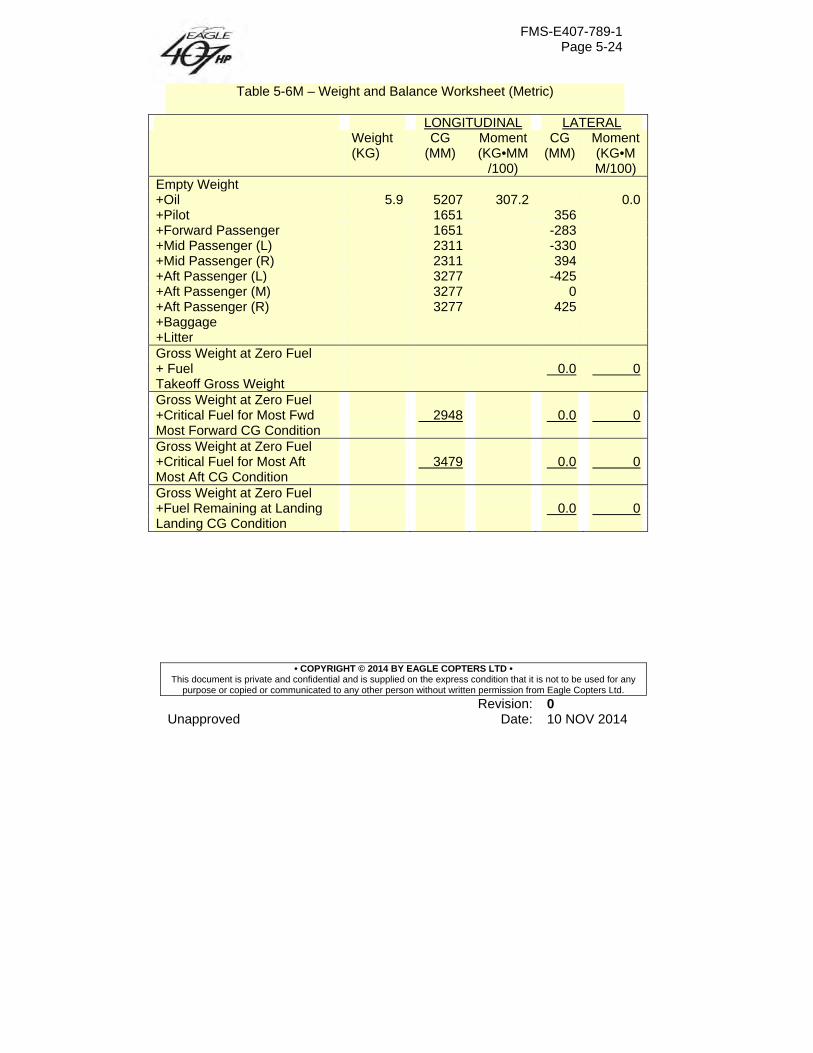
FMS-E407-789-1 Page 5-24
• COPYRIGHT © 2014 BY EAGLE COPTERS LTD • This document is private and confidential and is supplied on the express condition that it is not to be used for any
purpose or copied or communicated to any other person without written permission from Eagle Copters Ltd.
Revision: 0 Unapproved Date: 10 NOV 2014
Table 5-6M – Weight and Balance Worksheet (Metric)
LONGITUDINAL LATERAL Weight
(KG) CG
(MM) Moment (KG•MM
/100)
CG (MM)
Moment (KG•MM/100)
Empty Weight +Oil 5.9 5207 307.2 0.0 +Pilot 1651 356 +Forward Passenger 1651 -283 +Mid Passenger (L) 2311 -330 +Mid Passenger (R) 2311 394 +Aft Passenger (L) 3277 -425 +Aft Passenger (M) 3277 0 +Aft Passenger (R) 3277 425 +Baggage +Litter Gross Weight at Zero Fuel + Fuel 0.0 0 Takeoff Gross Weight Gross Weight at Zero Fuel +Critical Fuel for Most Fwd 2948 0.0 0 Most Forward CG Condition Gross Weight at Zero Fuel +Critical Fuel for Most Aft 3479 0.0 0 Most Aft CG Condition Gross Weight at Zero Fuel +Fuel Remaining at Landing 0.0 0 Landing CG Condition