honeywell gsmvlp-install-guide
TRANSCRIPT

GSMVLP/GSMVLPCNGSMVLP/GSMVLPCNGSMVLP/GSMVLPCNGSMVLP/GSMVLPCN GSM Module with 2GSM Module with 2GSM Module with 2GSM Module with 2----Way VoiceWay VoiceWay VoiceWay Voice
Installation and Programming Guide
800-04954V4 7/11 Rev. A
– 2 –
Table of Contents
– 3 –
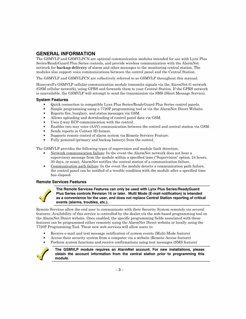
GENERAL INFORMATION
System Features • • • • • • • • •
•
•
Remote Services Features
The Remote Services Features can only be used with Lynx Plus Series/ReadyGuard Plus Series controls Revision 16 or later. Multi Mode (E-mail notification) is intended as a convenience for the user, and does not replace Central Station reporting of critical events (alarms, troubles, etc.).
• • •
The GSMVLP module requires an AlarmNet account. For new installations, please obtain the account information from the central station prior to programming this module.
– 4 –
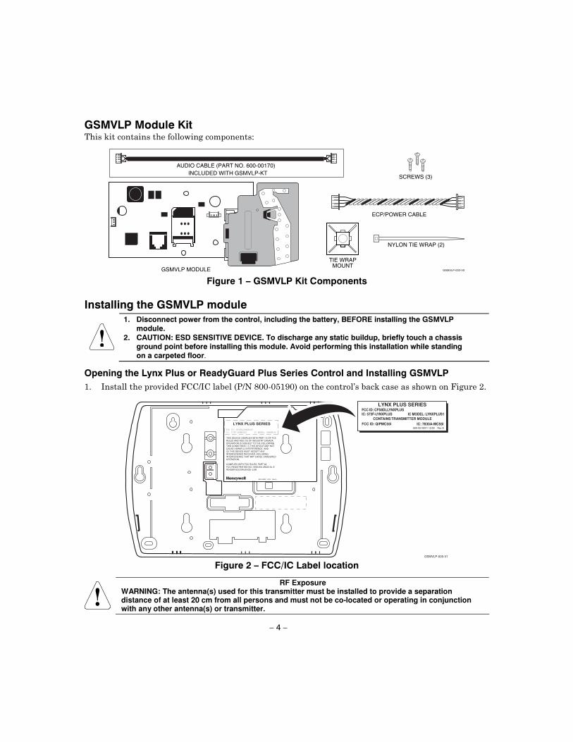
GSMVLP Module Kit
AUDIO CABLE (PART NO. 600-00170)
GSMVLP-003-V0
ECP/POWER CABLE
TIE WRAPMOUNT
NYLON TIE WRAP (2)
SCREWS (3)
GSMVLP MODULE
INCLUDED WITH GSMVLP-KT
Figure 1 – GSMVLP Kit Components
Installing the GSMVLP module
1. Disconnect power from the control, including the battery, BEFORE installing the GSMVLP module.
2. CAUTION: ESD SENSITIVE DEVICE. To discharge any static buildup, briefly touch a chassis ground point before installing this module. Avoid performing this installation while standing on a carpeted floor.
Opening the Lynx Plus or ReadyGuard Plus Series Control and Installing GSMVLP
GSMVLP-005-V1
FCC ID: CFS8DLLYNXPLUS
IC: 573F-LYNXPLUS
THIS DEVICE COMPLIES WITH PART 15 OF FCCRULES AND RSS 210 OF INDUSTRY CANADA.OPERATION IS SUBJECT TO THE FOLLOWINGTWO CONDITIONS: (1) THIS DEVICE MAY NOTCAUSE HARMFUL INTERFERENCE, AND(2) THIS DEVICE MUST ACCEPT ANYINTERFERENCE RECEIVED, INCLUDINGINTERFERENCE THAT MAY CAUSE UNDESIREDOPERATION.
800-04399 9/09 Rev A
LYNX PLUS SERIES
COMPLIES WITH FCC RULES, PART 68FCC REGISTRATION NO.: 5GBUSA-25623-AL-ERINGER EQUIVALENCE: 0.6B
IC MODEL: LYNXPLUS
CONTAINS TRANSMITTER MODULE
IC: 7830A-MC55IFCC ID: QIPMC55I800-05190V1 12/09 Rev A
FCC ID: CFS8DLLYNXPLUSIC: 573F-LYNXPLUS
LYNX PLUS SERIES
IC MODEL: LYNXPLUS1
Figure 2 – FCC/IC Label location
RF Exposure WARNING: The antenna(s) used for this transmitter must be installed to provide a separation distance of at least 20 cm from all persons and must not be co-located or operating in conjunction with any other antenna(s) or transmitter.
– 5 –
BACKCASE
GSMVLP-002-V0
TAPE
WIRE STRAINRELIEF CLIP
FRONTCASE
LOCKING TABS
TIE WRAPMOUNT
SCREW(3)
GSMVLP
ECP/POWERCABLE
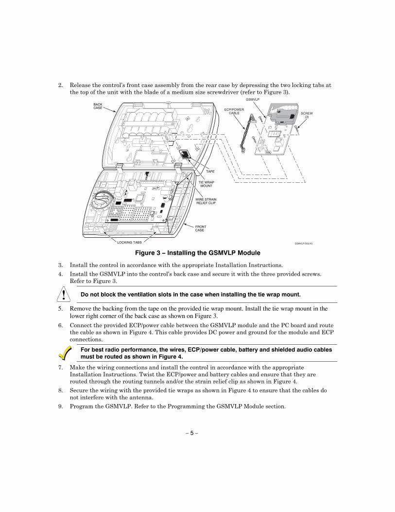
Figure 3 – Installing the GSMVLP Module
Do not block the ventilation slots in the case when installing the tie wrap mount.
5. Remove the backing from the tape on the provided tie wrap mount. Install the tie wrap mount in the lower right corner of the back case as shown on Figure 3.
For best radio performance, the wires, ECP/power cable, battery and shielded audio cables must be routed as shown in Figure 4.

– 6 –
BACK CASE
GSMVLP-001-V1
AUDIOCABLE
MOUNTINGHOOK
7720PPROGRAMMINGJACK
TIE-WRAPPOINT
WIREROUTINGTUNNELS
TIE WRAP
TIE WRAP
FRONT CASE
ECP/POWER CABLE
BATTERY CABLE
TIE WRAP MOUNT
MOUNTING HOOK
NOTEENSURE ALL WIRING IS
ROUTED THROUGH WIRESTRAIN RELIEF CLIP
Figure 4 – GSMVLP Wiring Connections and Routing
Programming the GSMVLP Module
• •
Using the AlarmNet Direct website
https://services.alarmnet.com/AlarmNetDirect/userlogin.aspx

– 7 –
Using a 7720P Programming Tool • •
7720P PROGRAMMING JACK
MESSAGE STATUS LEDs
MINIMUM SIGNAL STRENGTH LED
GS
MV
LP
-004-V
1
A B C
D E F
S T X
Xmit
Shift
Space EnterShift
N / Y
BS / ESC
/
7720 PROGRAMMING TOOL
#0
1 2 3
4 5 6
987
Figure 5 – 7720P Connection
Table 1 – 7720P Normal and Shift Key (shift LED lit) Functions
KEY NORMAL KEY FUNCTION SHIFT KEY FUNCTION BS/ESC [BS]: Press to delete entry [ESC]: Press to quit program mode; also can reset
programming defaults*
!/" [!]: Scroll down programming ["]: Scroll up programming N/Y [N]: Press for "NO" answer [Y]: Press SHIFT-Y for "YES" answer SHIFT Press before pressing a SHIFT key function. Will light SHIFT LED. LED goes out once a key is pressed.
Press again for each SHIFT function desired. 1/A [1]: For entering the number 1 [A]: For entering letter A 2/B [2]: For entering the number 2 [B]: For entering letter B 3/C [3]: For entering the number 3 [C]: For entering letter C 4/D [4]: For entering the number 4 [D]: For entering letter D 5/E [5]: For entering the number 5 [E]: For entering letter E 6/F [6]: For entering the number 6 [F]: For entering letter F 7/S [7]: For entering the number 7 [S]: For entering letter S 8/T [8]: For entering the number 8 [T]: For entering letter T 9/X [9]: For entering the number 9 [X]: For entering letter X SPACE [SPACE]: For scrolling option list No SHIFT function 0 [0]: For entering the number 0 No SHIFT function #/ENTER [#/ENTER]: Starts programming
mode; Press to accept entries No SHIFT function
– 8 –
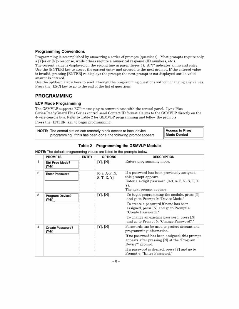
Programming Conventions
PROGRAMMING
ECP Mode Programming
NOTE: The central station can remotely block access to local device programming. If this has been done, the following prompt appears:
Access to Prog Mode Denied
Table 2 – Programming the GSMVLP Module
NOTE: The default programming values are listed in the prompts below.
PROMPTS ENTRY OPTIONS DESCRIPTION
1
Strt Prog Mode? (Y/N)_
2
Enter Password
3
Program Device? (Y/N)_
4 Create Password? (Y/N)_
– 9 –
PROMPTS ENTRY OPTIONS DESCRIPTION
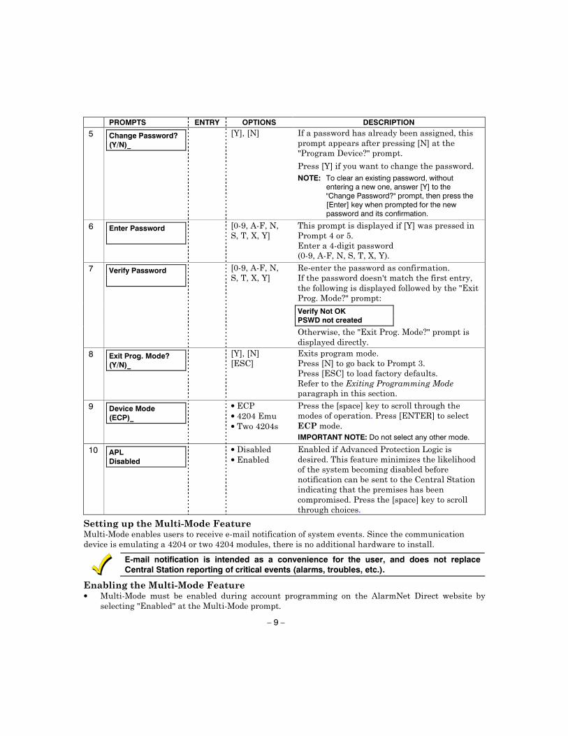
5 Change Password? (Y/N)_
NOTE: To clear an existing password, without
entering a new one, answer [Y] to the "Change Password?" prompt, then press the [Enter] key when prompted for the new password and its confirmation.
6 Enter Password
7
Verify Not OK PSWD not created
Verify Password
8 Exit Prog. Mode? (Y/N)_
9
Device Mode (ECP)_
•••
IMPORTANT NOTE: Do not select any other mode.
10
APL Disabled
••
E-mail notification is intended as a convenience for the user, and does not replace Central Station reporting of critical events (alarms, troubles, etc.).
•
– 10 –
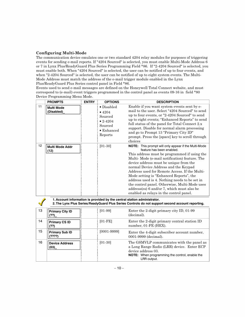
PROMPTS ENTRY OPTIONS DESCRIPTION
11
Multi Mode (Disabled)_
••••
12
Multi Mode Addr (12)
NOTE: This prompt will only appear if the Multi-Mode feature has been enabled.
1. Account information is provided by the central station administrator. 2. The Lynx Plus Series/ReadyGuard Plus Series Controls do not support second account reporting.
13 Primary City ID (??)_
14
Primary CS ID (??)
15
Primary Sub ID (????)
16
Device Address (03)_
NOTE: When programming the control, enable the
LRR output.

– 11 –
•
•
PROMPTS ENTRY OPTIONS DESCRIPTION
17
Remote Access Y/N (N)_
18
Keypad Address (28)_
NOTE: This prompt will only appear if the Remote Access feature has been enabled.
NOTE: This address must be set to “1”.
19
Supervision (24 Hours)_
•••
UL NOTE: Must be 24 hour.
20
Old Alarm Time (10 Minutes)_
•••••••••
UL NOTE: Must be 10 minutes.
21
GSM Flt Time (00 mins)_
UL NOTE: Must be one (01) minute.
– 12 –
PROMPTS ENTRY OPTIONS DESCRIPTION
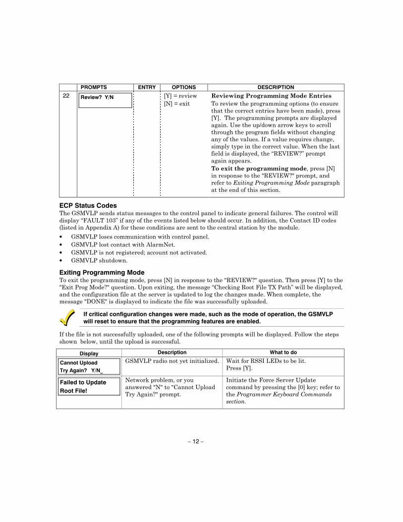
22
Review? Y/N
ECP Status Codes • • • •
Exiting Programming Mode
If critical configuration changes were made, such as the mode of operation, the GSMVLP will reset to ensure that the programming features are enabled.
Display Description What to do
Cannot Upload
Try Again? Y/N_
Failed to Update
Root File!
– 13 –
Setting Factory Defaults
Set Default? Y/N_
IMPORTANT NOTE: THIS WILL ERASE ANY PASSWORD THAT MAY HAVE BEEN ENTERED.
REGISTRATION
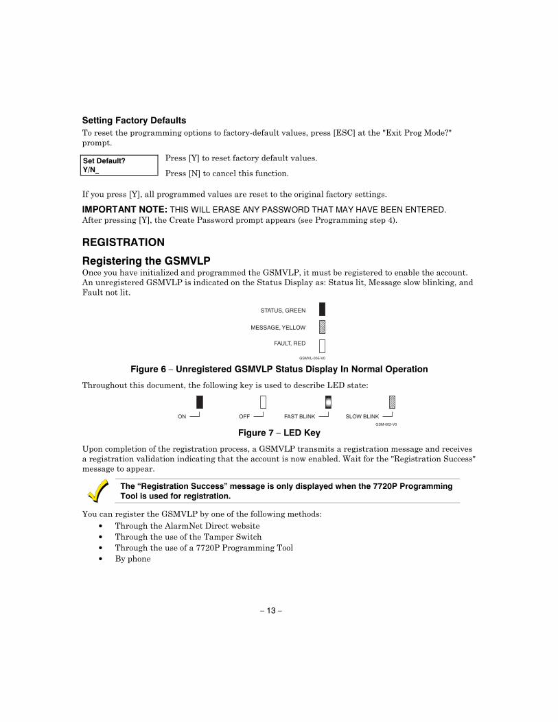
Registering the GSMVLP
GSMVL-005-V0
FAULT, RED
MESSAGE, YELLOW
STATUS, GREEN
Figure 6 – Unregistered GSMVLP Status Display In Normal Operation
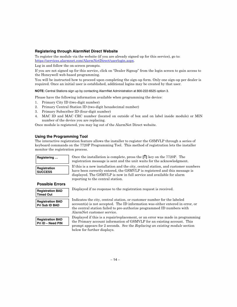
ON
GSM-002-V0
OFF FAST BLINK SLOW BLINK
Figure 7 – LED Key
The “Registration Success” message is only displayed when the 7720P Programming Tool is used for registration.
• • • •
– 14 –
Registering through AlarmNet Direct Website
NOTE: Central Stations sign up by contacting AlarmNet Administration at 800-222-6525 option 3.
Using the Programming Tool
Registering …
""""
Registration SUCCESS
Possible Errors
Registration BAD Timed Out
Registration BAD Pri Sub ID BAD
Registration BAD Pri ID – Need PIN
– 15 –
Replacing an existing module using the programming tool
Enter PIN#
!!!!NOTE: If you are replacing an existing "C Series" radio, you can enter the last four-digits of
the "C Series" MIN number.
Registering …
Registration SUCCESS
Registration BAD
NOTE: Each attempt causes a substitution alarm to be sent to the central station.
Register by Phone • •
•
– 16 –
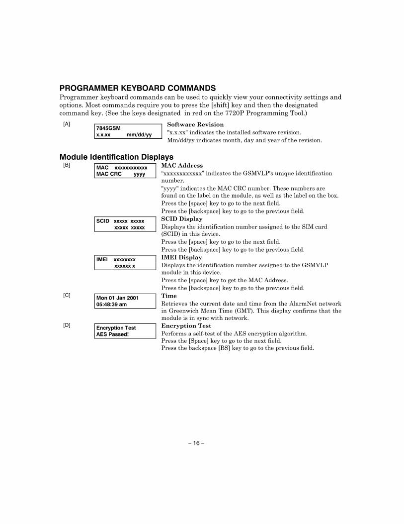
PROGRAMMER KEYBOARD COMMANDS
[A]
7845GSM x.x.xx mm/dd/yy
Module Identification Displays [B]
MAC xxxxxxxxxxxx MAC CRC yyyy
SCID xxxxx xxxxx xxxxx xxxxx
IMEI xxxxxxxx xxxxxx x
[C]
Mon 01 Jan 2001 05:48:39 am
[D]
Encryption Test AES Passed!
– 17 –
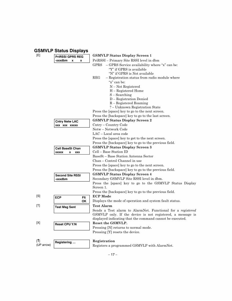
GSMVLP Status Displays [E]
PriRSSI GPRS REG -xxxdbm x x
Cntry Netw LAC xxx xxx xxxxx
Cell BaseSt Chan xxxxx x xxx
Second Site RSSI -xxxdbm
[S]
ECP Flt OK
[T]
Test Msg Sent
[X]
Reset CPU Y/N
[""""]
(UP arrow)
Registering …
– 18 –
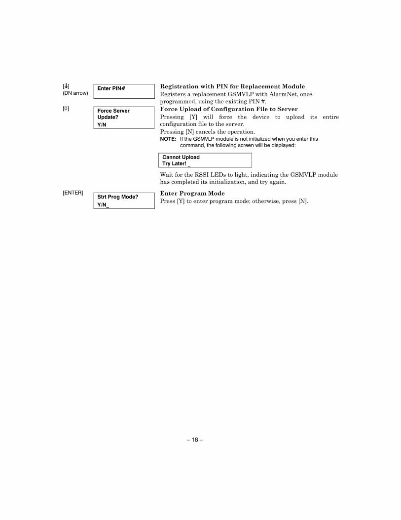
[!!!!]
(DN arrow)
Enter PIN#
NOTE: If the GSMVLP module is not initialized when you enter this
command, the following screen will be displayed:
Cannot Upload Try Later! _
[0]
Force Server Update?
Y/N
[ENTER]
Strt Prog Mode?
Y/N_
– 19 –
APPENDIX A
SUMMARY OF LED OPERATION
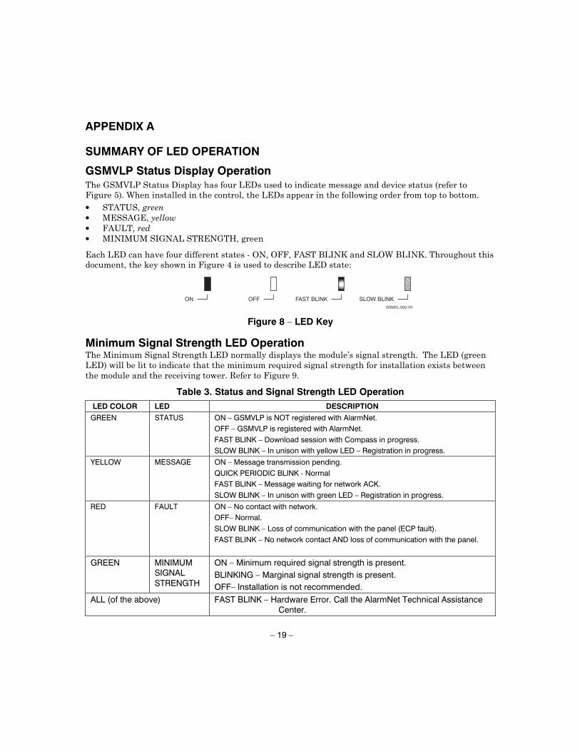
GSMVLP Status Display Operation • • • •
ON
GSMVL-002-V0
OFF FAST BLINK SLOW BLINK
Figure 8 – LED Key
Minimum Signal Strength LED Operation
Table 3. Status and Signal Strength LED Operation
LED COLOR LED DESCRIPTION
GREEN STATUS ON – GSMVLP is NOT registered with AlarmNet.
OFF – GSMVLP is registered with AlarmNet.
FAST BLINK – Download session with Compass in progress.
SLOW BLINK – In unison with yellow LED – Registration in progress.
YELLOW MESSAGE ON – Message transmission pending.
QUICK PERIODIC BLINK - Normal
FAST BLINK – Message waiting for network ACK.
SLOW BLINK – In unison with green LED – Registration in progress.
RED FAULT ON – No contact with network.
OFF– Normal.
SLOW BLINK – Loss of communication with the panel (ECP fault).
FAST BLINK – No network contact AND loss of communication with the panel.
GREEN MINIMUM SIGNAL STRENGTH
ON – Minimum required signal strength is present.
BLINKING – Marginal signal strength is present.
OFF– Installation is not recommended.
ALL (of the above) FAST BLINK – Hardware Error. Call the AlarmNet Technical Assistance Center.
– 20 –
FAULT, RED
MESSAGE, YELLOW
STATUS, GREEN
GSMVL-003-V0
A
FAULT, RED
MESSAGE, YELLOW
STATUS, GREEN
B
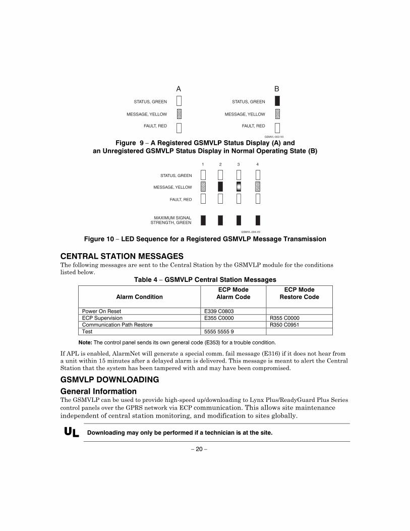
Figure 9 – A Registered GSMVLP Status Display (A) and
an Unregistered GSMVLP Status Display in Normal Operating State (B)
FAULT, RED
MESSAGE, YELLOW
STATUS, GREEN
GSMVL-004-V0
4321
MAXIMUM SIGNALSTRENGTH, GREEN
Figure 10 – LED Sequence for a Registered GSMVLP Message Transmission
CENTRAL STATION MESSAGES
Table 4 – GSMVLP Central Station Messages
Alarm Condition ECP Mode
Alarm Code
ECP Mode Restore Code
Power On Reset E339 C0803 ECP Supervision E355 C0000 R355 C0000 Communication Path Restore R350 C0951 Test 5555 5555 9
Note: The control panel sends its own general code (E353) for a trouble condition.
GSMVLP DOWNLOADING
General Information
UUUULLLL Downloading may only be performed if a technician is at the site.
– 21 –
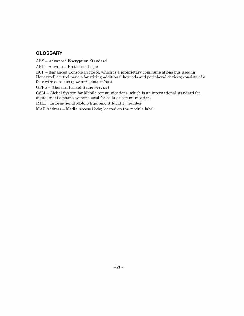
GLOSSARY
– 22 –
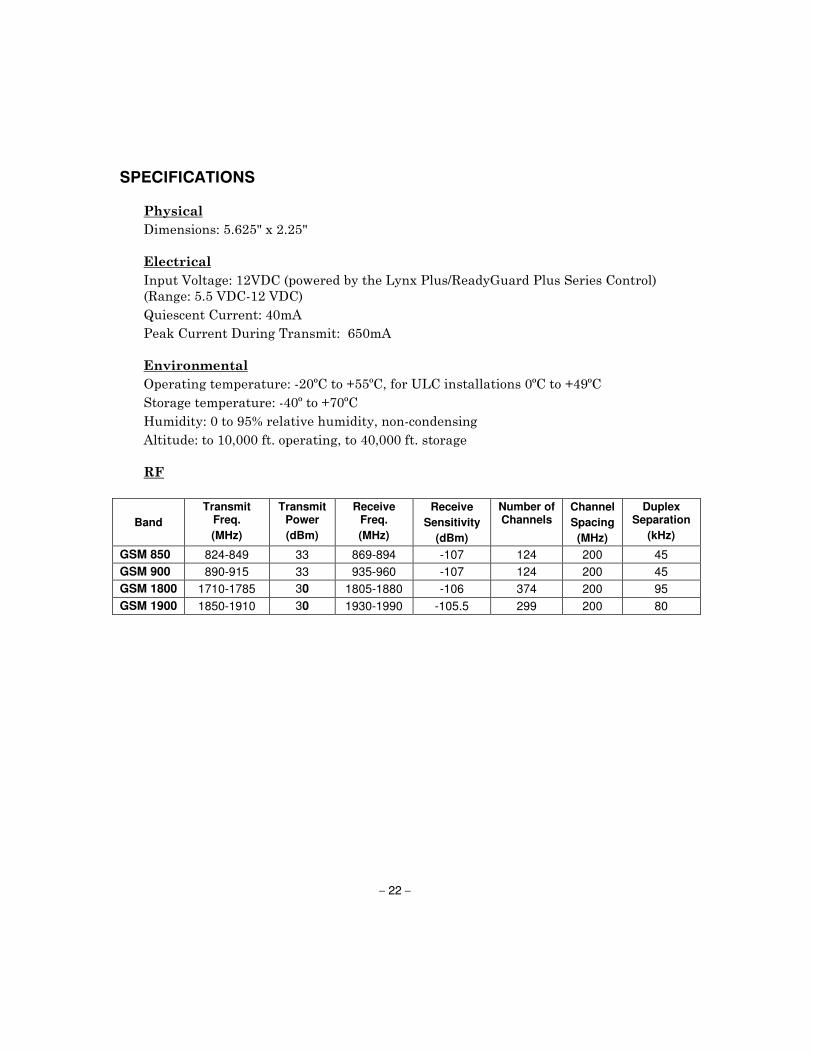
SPECIFICATIONS
Band
Transmit Freq.
(MHz)
Transmit Power
(dBm)
Receive Freq.
(MHz)
Receive
Sensitivity
(dBm)
Number of Channels
Channel
Spacing
(MHz)
Duplex Separation
(kHz)
GSM 850 824-849 33 869-894 -107 124 200 45
GSM 900 890-915 33 935-960 -107 124 200 45
GSM 1800 1710-1785 30 1805-1880 -106 374 200 95
GSM 1900 1850-1910 30 1930-1990 -105.5 299 200 80
– 23 –
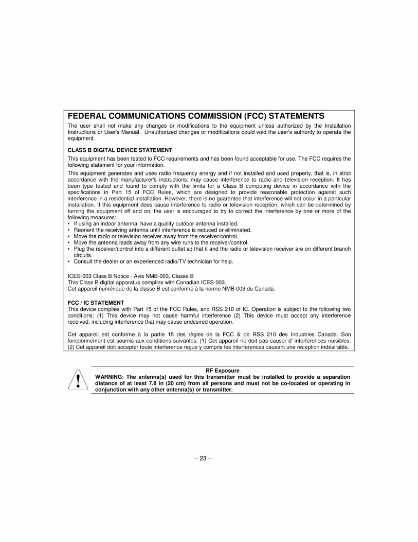
FEDERAL COMMUNICATIONS COMMISSION (FCC) STATEMENTS The user shall not make any changes or modifications to the equipment unless authorized by the Installation Instructions or User's Manual. Unauthorized changes or modifications could void the user's authority to operate the equipment.
CLASS B DIGITAL DEVICE STATEMENT
This equipment has been tested to FCC requirements and has been found acceptable for use. The FCC requires the following statement for your information.
This equipment generates and uses radio frequency energy and if not installed and used properly, that is, in strict accordance with the manufacturer's instructions, may cause interference to radio and television reception. It has been type tested and found to comply with the limits for a Class B computing device in accordance with the specifications in Part 15 of FCC Rules, which are designed to provide reasonable protection against such interference in a residential installation. However, there is no guarantee that interference will not occur in a particular installation. If this equipment does cause interference to radio or television reception, which can be determined by turning the equipment off and on, the user is encouraged to try to correct the interference by one or more of the following measures: • If using an indoor antenna, have a quality outdoor antenna installed. • Reorient the receiving antenna until interference is reduced or eliminated. • Move the radio or television receiver away from the receiver/control. • Move the antenna leads away from any wire runs to the receiver/control. • Plug the receiver/control into a different outlet so that it and the radio or television receiver are on different branch
circuits. • Consult the dealer or an experienced radio/TV technician for help.
ICES-003 Class B Notice - Avis NMB-003, Classe B This Class B digital apparatus complies with Canadian ICES-003. Cet appareil numérique de la classe B est conforme à la norme NMB-003 du Canada.
FCC / IC STATEMENT This device complies with Part 15 of the FCC Rules, and RSS 210 of IC. Operation is subject to the following two conditions: (1) This device may not cause harmful interference (2) This device must accept any interference received, including interference that may cause undesired operation. Cet appareil est conforme à la partie 15 des règles de la FCC & de RSS 210 des Industries Canada. Son fonctionnement est soumis aux conditions suivantes: (1) Cet appareil ne doit pas causer d' interferences nuisibles. (2) Cet appareil doit accepter toute interference reçue y compris les interferences causant une reception indésirable.
RF Exposure WARNING: The antenna(s) used for this transmitter must be installed to provide a separation distance of at least 7.8 in (20 cm) from all persons and must not be co-located or operating in conjunction with any other antenna(s) or transmitter.
DOCUMENTATION AND ONLINE SUPPORT For the latest documentation and online support information, please go to:
http://www.security.honeywell.com/hsc/resources/MyWebTech/
WARRANTY For the latest warranty information, please go to:
http://www.security.honeywell.com/hsc/resources/wa/
2 Corporate Center Drive, Suite 100P.O. Box 9040, Melville, NY 11747
Copyright © 2011 Honeywell International Inc.
www.honeywell.com/security
800-04954V4 7/11 Rev A