honeywell dpr100
TRANSCRIPT

DPR100 C - DPR100 D
PRODUCT MANUAL�
��
��
�
Better Record Your World
PRODUCT OF FRANCE Ref : EN1I-6137
DPR 100 C - DPR 100 D
PRODUCT MANUAL
Ref. : EN1I-6137
Issue : 18 July, 1999


Thank you for choosing a HONEYWELL DPR100 Recorder.
The product, designed and produced to ISO 9001, will serve you well and continue HONEYWELLS' traditionas a supplier of quality instrumentation.
To fully benefit from its many features and functions, we would ask you to carefully read this manual. Itdescribes how to prepare, install, configure and use your new recorder.
From first use, we are confident you will appreciate the user-friendly configuration, flexibility andcompleteness of chart information. Should you require further information, please do not hesitate to contactyour nearest HONEYWELL sales office.
If ever you should need assistance, we would ask you to have available the product model number, serialnumber and date code. This information is printed on a label attached to the case. We recommend tocomplete the table below with the same information.
A listing of HONEYWELL Sales and Service Offices is given at the end of this manual.
Product model number :
Serial number :
Date code :
Service department telephone number :
TABLE OF CONTENTS
1 OVERVIEW . . . . . . . . . . . . . . . . . . . . . . . . . . . . . . . . . . . . . . . . . . . . . . . . . . . . . . . . . . . . . . 1-1
1.1 RECORDER OVERVIEW . . . . . . . . . . . . . . . . . . . . . . . . . . . . . . . . . . . . . . . . . . . . . . . . . . . 1-1
2 INSTALLATION . . . . . . . . . . . . . . . . . . . . . . . . . . . . . . . . . . . . . . . . . . . . . . . . . . . . . . . . . . . 2-1
2.1 WARNING . . . . . . . . . . . . . . . . . . . . . . . . . . . . . . . . . . . . . . . . . . . . . . . . . . . . . . . . . . . . . 2-1
2.2 UNPACKING . . . . . . . . . . . . . . . . . . . . . . . . . . . . . . . . . . . . . . . . . . . . . . . . . . . . . . . . . . . 2-2
2.3 PANEL MOUNTING THE RECORDER . . . . . . . . . . . . . . . . . . . . . . . . . . . . . . . . . . . . . . . . . . 2-32.3.1 Recommendations . . . . . . . . . . . . . . . . . . . . . . . . . . . . . . . . . . . . . . . . . . . . . . . . . 2-32.3.2 External dimensions and cut-out. . . . . . . . . . . . . . . . . . . . . . . . . . . . . . . . . . . . . . . . 2-32.3.3 Installing the recorder . . . . . . . . . . . . . . . . . . . . . . . . . . . . . . . . . . . . . . . . . . . . . . . 2-4
2.4 WIRING THE RECORDER . . . . . . . . . . . . . . . . . . . . . . . . . . . . . . . . . . . . . . . . . . . . . . . . . . 2-52.4.1 Recommendations . . . . . . . . . . . . . . . . . . . . . . . . . . . . . . . . . . . . . . . . . . . . . . . . . 2-5
2.5 TERMINAL CONNECTIONS . . . . . . . . . . . . . . . . . . . . . . . . . . . . . . . . . . . . . . . . . . . . . . . . . 2-7
2.6 FITTING THE CHART . . . . . . . . . . . . . . . . . . . . . . . . . . . . . . . . . . . . . . . . . . . . . . . . . . . . . 2-82.6.1 Roll chart . . . . . . . . . . . . . . . . . . . . . . . . . . . . . . . . . . . . . . . . . . . . . . . . . . . . . . . 2-82.6.2 Fanfold chart. . . . . . . . . . . . . . . . . . . . . . . . . . . . . . . . . . . . . . . . . . . . . . . . . . . . . 2-9
2.7 INSTALLING THE PRINTING SYSTEM . . . . . . . . . . . . . . . . . . . . . . . . . . . . . . . . . . . . . . . . . . 2-10
2.8 CHECK LIST . . . . . . . . . . . . . . . . . . . . . . . . . . . . . . . . . . . . . . . . . . . . . . . . . . . . . . . . . . . 2-18
3 OPERATION . . . . . . . . . . . . . . . . . . . . . . . . . . . . . . . . . . . . . . . . . . . . . . . . . . . . . . . . . . . . . 3-1
3.1 OPERATOR INTERFACE EXPLANATION . . . . . . . . . . . . . . . . . . . . . . . . . . . . . . . . . . . . . . . . 3-1
3.2 BASIC ACTIONS . . . . . . . . . . . . . . . . . . . . . . . . . . . . . . . . . . . . . . . . . . . . . . . . . . . . . . . . . 3-23.2.1 Operators keys . . . . . . . . . . . . . . . . . . . . . . . . . . . . . . . . . . . . . . . . . . . . . . . . . . . 3-23.2.2 How to select the display type. . . . . . . . . . . . . . . . . . . . . . . . . . . . . . . . . . . . . . . . . . 3-3
4 PARTS LIST . . . . . . . . . . . . . . . . . . . . . . . . . . . . . . . . . . . . . . . . . . . . . . . . . . . . . . . . . . . . . 4-1
4.1 TO ORDER CONSUMABLES . . . . . . . . . . . . . . . . . . . . . . . . . . . . . . . . . . . . . . . . . . . . . . . . 4-1
1
TABLE OF CONTENTS
5 MODEL SELECTION GUIDE . . . . . . . . . . . . . . . . . . . . . . . . . . . . . . . . . . . . . . . . . . . . . . . . . . 5-1
5.1 PRODUCT IDENTIFICATION . . . . . . . . . . . . . . . . . . . . . . . . . . . . . . . . . . . . . . . . . . . . . . . . 5-1
6 PRODUCT SPECIFICATION SHEET . . . . . . . . . . . . . . . . . . . . . . . . . . . . . . . . . . . . . . . . . . . . . 6-1
7 CONFIGURATION . . . . . . . . . . . . . . . . . . . . . . . . . . . . . . . . . . . . . . . . . . . . . . . . . . . . . . . . . 7-1
7.1 OPERATOR INTERFACE . . . . . . . . . . . . . . . . . . . . . . . . . . . . . . . . . . . . . . . . . . . . . . . . . . . 7-1
7.2 ONE EXAMPLE : HOW TO SET THE CHART SPEED . . . . . . . . . . . . . . . . . . . . . . . . . . . . . . . . 7-5
7.3 PROMPTS EXPLANATION . . . . . . . . . . . . . . . . . . . . . . . . . . . . . . . . . . . . . . . . . . . . . . . . . . 7-6
8 DETAILED CONFIGURATION . . . . . . . . . . . . . . . . . . . . . . . . . . . . . . . . . . . . . . . . . . . . . . . . . 8-1
8.1 PARAMETERS LIST . . . . . . . . . . . . . . . . . . . . . . . . . . . . . . . . . . . . . . . . . . . . . . . . . . . . . . 8-1
9 SERVICE . . . . . . . . . . . . . . . . . . . . . . . . . . . . . . . . . . . . . . . . . . . . . . . . . . . . . . . . . . . . . . . 9-1
9.1 OPERATOR INTERFACE . . . . . . . . . . . . . . . . . . . . . . . . . . . . . . . . . . . . . . . . . . . . . . . . . . . 9-19.1.1 ACCESS TO SERVICE . . . . . . . . . . . . . . . . . . . . . . . . . . . . . . . . . . . . . . . . . . . . . . 9-19.1.2 PASSWORDS . . . . . . . . . . . . . . . . . . . . . . . . . . . . . . . . . . . . . . . . . . . . . . . . . . . . 9-19.1.3 MAIN FUNCTION . . . . . . . . . . . . . . . . . . . . . . . . . . . . . . . . . . . . . . . . . . . . . . . . . 9-19.1.4 ACCESS TO FUNCTIONS DURING SERVICE . . . . . . . . . . . . . . . . . . . . . . . . . . . . . . 9-3
9.2 LIST OF SERVICES. . . . . . . . . . . . . . . . . . . . . . . . . . . . . . . . . . . . . . . . . . . . . . . . . . . . . . . 9-4
10 PC LOADER . . . . . . . . . . . . . . . . . . . . . . . . . . . . . . . . . . . . . . . . . . . . . . . . . . . . . . . . . . . . . 10-1
10.1 OVERVIEW . . . . . . . . . . . . . . . . . . . . . . . . . . . . . . . . . . . . . . . . . . . . . . . . . . . . . . . . . . . . 10-1
10.2 REQUIRED MATERIAL . . . . . . . . . . . . . . . . . . . . . . . . . . . . . . . . . . . . . . . . . . . . . . . . . . . . 10-1
10.3 PRODUCT FEATURES . . . . . . . . . . . . . . . . . . . . . . . . . . . . . . . . . . . . . . . . . . . . . . . . . . . . 10-1
10.4 INSTALLATION . . . . . . . . . . . . . . . . . . . . . . . . . . . . . . . . . . . . . . . . . . . . . . . . . . . . . . . . . . 10-210.4.1 Copying your master floppy disk . . . . . . . . . . . . . . . . . . . . . . . . . . . . . . . . . . . . . . . . 10-210.4.2 Installing the software on the hard disk. . . . . . . . . . . . . . . . . . . . . . . . . . . . . . . . . . . . 10-210.4.3 Use . . . . . . . . . . . . . . . . . . . . . . . . . . . . . . . . . . . . . . . . . . . . . . . . . . . . . . . . . . . 10-3
2
TABLE OF CONTENTS
10 PC LOADER (continued)10.4.3.1 Operating the application software . . . . . . . . . . . . . . . . . . . . . . . . . . . . . . . . . . . . . 10-310.4.3.2 Using the keyboard or the mouse . . . . . . . . . . . . . . . . . . . . . . . . . . . . . . . . . . . . . 10-3
10.5 SET UP COMM . . . . . . . . . . . . . . . . . . . . . . . . . . . . . . . . . . . . . . . . . . . . . . . . . . . . . . . . . . 10-4
10.6 CONFIGURATION. . . . . . . . . . . . . . . . . . . . . . . . . . . . . . . . . . . . . . . . . . . . . . . . . . . . . . . . 10-510.6.1 Read and modify . . . . . . . . . . . . . . . . . . . . . . . . . . . . . . . . . . . . . . . . . . . . . . . . . . 10-510.6.2 User actuation . . . . . . . . . . . . . . . . . . . . . . . . . . . . . . . . . . . . . . . . . . . . . . . . . . . . 10-5
10.6.2.1 Definition of a user actuation. . . . . . . . . . . . . . . . . . . . . . . . . . . . . . . . . . . . . . . . . 10-510.6.2.2 Select the type of sensor . . . . . . . . . . . . . . . . . . . . . . . . . . . . . . . . . . . . . . . . . . . 10-5
10.7 "SERVICE" PARAMETERS . . . . . . . . . . . . . . . . . . . . . . . . . . . . . . . . . . . . . . . . . . . . . . . . . . 10-6
10.8 MONITORING. . . . . . . . . . . . . . . . . . . . . . . . . . . . . . . . . . . . . . . . . . . . . . . . . . . . . . . . . . . 10-910.8.1 PARAMETERS INITIALIZATION . . . . . . . . . . . . . . . . . . . . . . . . . . . . . . . . . . . . . . . . 10-910.8.2 REAL TIME DISPLAY . . . . . . . . . . . . . . . . . . . . . . . . . . . . . . . . . . . . . . . . . . . . . . . 10-910.8.3 START/STOP ARCHIVING . . . . . . . . . . . . . . . . . . . . . . . . . . . . . . . . . . . . . . . . . . . 10-9
10.9 UPDATE SOFTWARE (FOR JACK ONLY) . . . . . . . . . . . . . . . . . . . . . . . . . . . . . . . . . . . . . . . 10-10
11 TROUBLESHOOTING . . . . . . . . . . . . . . . . . . . . . . . . . . . . . . . . . . . . . . . . . . . . . . . . . . . . . . . 11-1
11.1 FAILURE SYMPTOMS AND TROUBLESHOOTING PROCEDURES . . . . . . . . . . . . . . . . . . . . . . 11-1
11.2 TROUBLESHOOTING LIST . . . . . . . . . . . . . . . . . . . . . . . . . . . . . . . . . . . . . . . . . . . . . . . . . . 11-111.2.1 SELF-TEST MODE PEN RECORDER . . . . . . . . . . . . . . . . . . . . . . . . . . . . . . . . . . . 11-1
11.2.1.1 Diagnostic pen recorder. . . . . . . . . . . . . . . . . . . . . . . . . . . . . . . . . . . . . . . . . . . . 11-111.2.1.2 Running in pen recorder . . . . . . . . . . . . . . . . . . . . . . . . . . . . . . . . . . . . . . . . . . . 11-211.2.1.3 APPENDIX . . . . . . . . . . . . . . . . . . . . . . . . . . . . . . . . . . . . . . . . . . . . . . . . . . . . 11-3
11.2.2 SELF-TEST MODE FOR MULTIPOINT RECORDER. . . . . . . . . . . . . . . . . . . . . . . . . . 11-511.2.2.1 Multipoint recorder diagnostic . . . . . . . . . . . . . . . . . . . . . . . . . . . . . . . . . . . . . . . . 11-511.2.2.2 Running in multipoint recorder . . . . . . . . . . . . . . . . . . . . . . . . . . . . . . . . . . . . . . . 11-611.2.2.3 APPENDIX . . . . . . . . . . . . . . . . . . . . . . . . . . . . . . . . . . . . . . . . . . . . . . . . . . . . 11-7
11.2.3 SYMPTOM : The recorder is inoperative. . . . . . . . . . . . . . . . . . . . . . . . . . . . . . . . . . . 11-811.2.4 SYMPTOM : The display is inoperative . . . . . . . . . . . . . . . . . . . . . . . . . . . . . . . . . . . . 11-811.2.5 SYMPTOM : The chart is inoperative . . . . . . . . . . . . . . . . . . . . . . . . . . . . . . . . . . . . . 11-911.2.6 SYMPTOM : The print carriage is inoperative . . . . . . . . . . . . . . . . . . . . . . . . . . . . . . . 11-911.2.7 SYMPTOM : The print head is inoperative . . . . . . . . . . . . . . . . . . . . . . . . . . . . . . . . . 11-1011.2.8 SYMPTOM : Printing incorrect color (only for the
multipoint recorder) . . . . . . . . . . . . . . . . . . . . . . . . . . . . . . . . . . . . . . . . . . . . . . . 11-1011.2.9 SYMPTOM : Wrong date/time. . . . . . . . . . . . . . . . . . . . . . . . . . . . . . . . . . . . . . . . . 11-1111.2.10 SYMPTOM : The alarm relay is inoperative or does not
have the desired effect . . . . . . . . . . . . . . . . . . . . . . . . . . . . . . . . . . . . . . . . . . . . . 11-11
3
TABLE OF CONTENTS
11 TROUBLESHOOTING (continued)11.2.11 SYMPTOM : Analog input records outside specified
accuracy tolerance . . . . . . . . . . . . . . . . . . . . . . . . . . . . . . . . . . . . . . . . . . . . . . . . 11-1111.2.12 SYMPTOM : Too much space between points (Multipoint
recorder only) . . . . . . . . . . . . . . . . . . . . . . . . . . . . . . . . . . . . . . . . . . . . . . . . . . . 11-1211.2.13 SYMPTOM : No communication with PC loader . . . . . . . . . . . . . . . . . . . . . . . . . . . . . 11-1211.2.14 SYMPTOM : The printed traces are unstable . . . . . . . . . . . . . . . . . . . . . . . . . . . . . . . 11-1211.2.15 SYMPTOM : The chart illumination failed. . . . . . . . . . . . . . . . . . . . . . . . . . . . . . . . . . 11-1311.2.16 SYMPTOM : The current output failed . . . . . . . . . . . . . . . . . . . . . . . . . . . . . . . . . . . 11-13
12 KITS LIST . . . . . . . . . . . . . . . . . . . . . . . . . . . . . . . . . . . . . . . . . . . . . . . . . . . . . . . . . . . . . . . 12-1
13 PROMPTS TRANSLATIONS . . . . . . . . . . . . . . . . . . . . . . . . . . . . . . . . . . . . . . . . . . . . . . . . . . 13-1
13.1 MATRICES. . . . . . . . . . . . . . . . . . . . . . . . . . . . . . . . . . . . . . . . . . . . . . . . . . . . . . . . . . . . . 13-1
13.2 SERVICE . . . . . . . . . . . . . . . . . . . . . . . . . . . . . . . . . . . . . . . . . . . . . . . . . . . . . . . . . . . . . 13-9
13.3 MESSAGES DURING RUN DISPLAY . . . . . . . . . . . . . . . . . . . . . . . . . . . . . . . . . . . . . . . . . . 13-12
14 CONFIGURATION WORKSHEET . . . . . . . . . . . . . . . . . . . . . . . . . . . . . . . . . . . . . . . . . . . . . . . 14-1
14.1 ANALOG INPUTS . . . . . . . . . . . . . . . . . . . . . . . . . . . . . . . . . . . . . . . . . . . . . . . . . . . . . . . . 14-1
14.2 ANALOG ALARMS . . . . . . . . . . . . . . . . . . . . . . . . . . . . . . . . . . . . . . . . . . . . . . . . . . . . . . . 14-1
14.3 MATH . . . . . . . . . . . . . . . . . . . . . . . . . . . . . . . . . . . . . . . . . . . . . . . . . . . . . . . . . . . . . . . . 14-2
14.4 DIGITAL INPUTS. . . . . . . . . . . . . . . . . . . . . . . . . . . . . . . . . . . . . . . . . . . . . . . . . . . . . . . . . 14-2
14.5 MESSAGES . . . . . . . . . . . . . . . . . . . . . . . . . . . . . . . . . . . . . . . . . . . . . . . . . . . . . . . . . . . . 14-3
14.6 CHART . . . . . . . . . . . . . . . . . . . . . . . . . . . . . . . . . . . . . . . . . . . . . . . . . . . . . . . . . . . . . . . 14-3
14.7 MISCELLANEOUS . . . . . . . . . . . . . . . . . . . . . . . . . . . . . . . . . . . . . . . . . . . . . . . . . . . . . . . 14-4
14.8 BATCH . . . . . . . . . . . . . . . . . . . . . . . . . . . . . . . . . . . . . . . . . . . . . . . . . . . . . . . . . . . . . . . 14-4
14.9 PRINTER . . . . . . . . . . . . . . . . . . . . . . . . . . . . . . . . . . . . . . . . . . . . . . . . . . . . . . . . . . . . . . 14-5
14.10 EVENT . . . . . . . . . . . . . . . . . . . . . . . . . . . . . . . . . . . . . . . . . . . . . . . . . . . . . . . . . . . . . . . 14-6
4

TABLE OF CONTENTS
14 CONFIGURATION WORKSHEET (continued)
14.11 MMI . . . . . . . . . . . . . . . . . . . . . . . . . . . . . . . . . . . . . . . . . . . . . . . . . . . . . . . . . . . . . . . . . 14-6
14.12 CURRENT OUTPUT . . . . . . . . . . . . . . . . . . . . . . . . . . . . . . . . . . . . . . . . . . . . . . . . . . . . . . 14-6
5

TABLE OF CONTENTS
LIST OF FIGURES
11-1 . . . . . . . . . . . . . . . . . . . . . . . . . . . . . . . . . . . . . . . . . . . . . . . . 11-311-2 . . . . . . . . . . . . . . . . . . . . . . . . . . . . . . . . . . . . . . . . . . . . . . . . 11-411-3 . . . . . . . . . . . . . . . . . . . . . . . . . . . . . . . . . . . . . . . . . . . . . . . . 11-7
6

1. OVERVIEW
1.1 RECORDER OVERVIEW
This recorder is a precision measuring instrument with many features.
2 Up to 3 pens for the pen recorder or up to 6 channels for the multipoint recorder,
2 Compact size : 245 mm depth,
2 100 mm chart in either roll or fanfold presentation,
2 Universal power supply :with optional 24 Vdc output voltage to supply up to 2 transmitters,
2 IP54 front of panel protection,
2 Universal input with wide choice of actuation/range,
2 High accuracy : 0.1 % F.S.,
2 Easy interactive product configuration,
2 Large, clear operator display,
2 Fast scanning rate : 330 ms for 3 channels, 640 ms for 6 channels,
2 Alphanumeric chart documentation,
2 Up to 12 alarm setpoints with a wide choice of alarm types,
2 Event alarm : end of chart paper, sensor burnout, clock battery low, etc.,
2 Up to 12 customer messages,
2 4 Batch messages,
2 Event precursor,
2 Standard chart illumination,
2 Up to 4 digital inputs,
2 Product configurability and service diagnostic with PC software,
2 Supervision display via PC software,
2 Chart zoning configurable,
1-1

1. OVERVIEW
2 Complies with IEC348 and IEC1010 safety requirements,
OPTIONS :
2 Up to 12 alarm relay outputs,
2 Maths functions,
2 Up to 2 current output channels (4 to 20 mA).
1-2

2. INSTALLATION
2.1 WARNING
To avoid the risk of electrical shock which could cause personal injury, follow all safety notices in thisdocumentation.
Protective earth terminal. Provided for connection of the protective earth supply system conductor.
9 POWER SUPPLYEnsure the source voltage matches the supply voltage of the recorder before power on.
9 PROTECTIVE GROUNDINGMake sure to connect the protective grounding to prevent an electric shock before power on.
9 NECESSITY OF PROTECTIVE GROUNDINGTo avoid a potential shock hazard, never cut off the internal or external protective grounding wire or disconnectthe wiring of protective grounding terminal.
9 DEFECT OF PROTECTIVE GROUNDING AND FUSEDo not operate the instrument when protective grounding or fuse might be defective.
9 FUSETo prevent a fire, make sure to use the fuse with specified standard (current voltage, type). Before replacingthe fuse, turn off the power and disconnect the power source. Do not use a different fuse or short-circuit thefuse holder.
9 DO NOT OPERATE IN AN EXPLOSIVE ATMOSPHEREDo not operate the instrument in the presence of flammable liquids or vapors. Operation of any electricalinstrument in such an environment constitutes a safety hazard.
9 NEVER TOUCH THE INTERIOR OF THE INSTRUMENTInside this instrument there are areas of high voltage ; therefore, never touch the interior if the power supply isconnected. This instrument has an internal changeable system ; however, internal inspection and adjustmentsshould be done by qualified personnel only.
9 EXTERNAL CONNECTIONTo ground securely, connect the protective grounding before connecting to measurement or control unit.
9 If the equipment is used in a manner not specified by the manufacturer, the protection provided by theequipment may be impaired.
9 Do not replace any component (or part) not explicitly specified as replaceable by your supplier.
2-1

2. INSTALLATION
2.2 UNPACKING
Remove the accessories and check them against the figure below.
1. Ink cartridge(s) (A) or ink wheel (B)
2. Fuse (Spare) (Use only 1 A T. fuses)
3. Roll (R) or fan fold (Z) chart
4. Mounting brackets with nuts
5. Operator manual
6. Front label
NOTE: In case of missing item, please contact your nearest sales office.
2-2
2. INSTALLATION
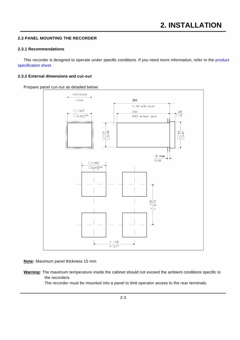
2.3 PANEL MOUNTING THE RECORDER
2.3.1 Recommendations
This recorder is designed to operate under specific conditions. If you need more information, refer to the productspecification sheet.
2.3.2 External dimensions and cut-out
Prepare panel cut-out as detailed below:����������
����������
����������
����������
����������
����������
����������
����������
����������
����������
��
��
Note: Maximum panel thickness 15 mm
Warning: The maximum temperature inside the cabinet should not exceed the ambient conditions specific tothe recorders.The recorder must be mounted into a panel to limit operator access to the rear terminals.
2-3
2. INSTALLATION
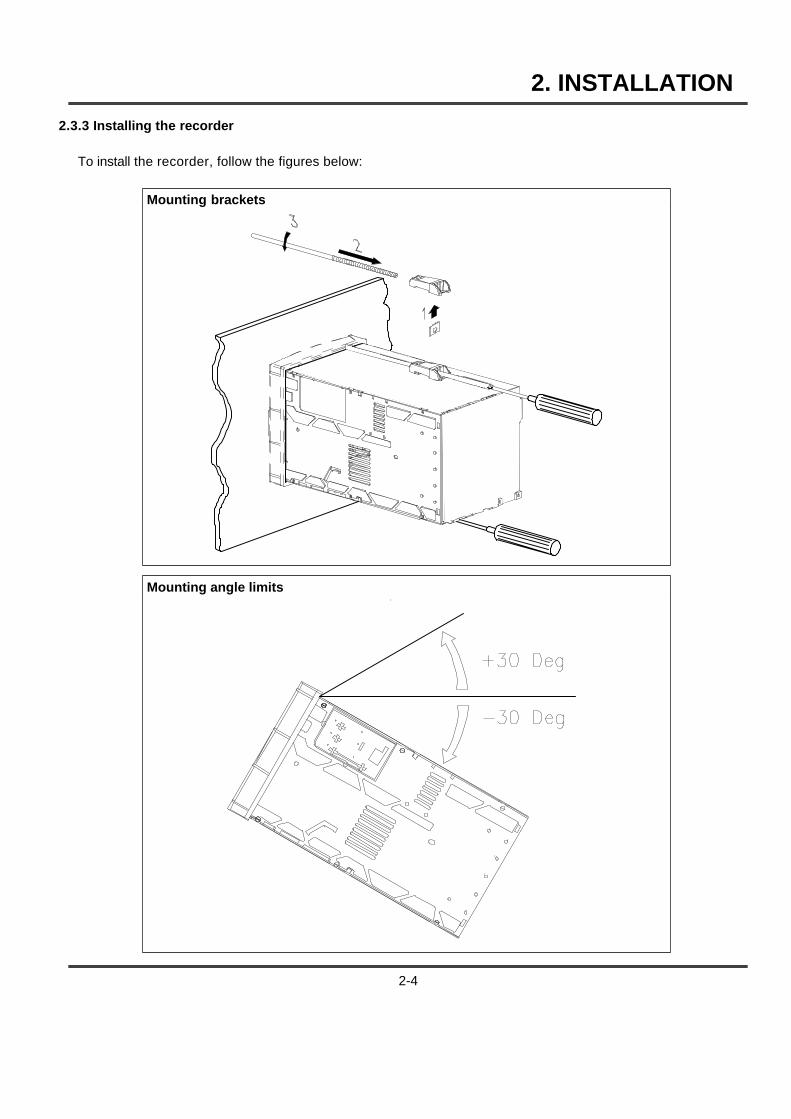
2.3.3 Installing the recorder
To install the recorder, follow the figures below:
Mounting brackets
Mounting angle limits
2-4

2. INSTALLATION
2.4 WIRING THE RECORDER
2.4.1 Recommendations
5 All wiring must be in accordance with local norms and carried out by authorized experienced personnel.
5 The ground terminal must be connected before any other wiring (and disconnected last).
5 A switch in the main supply is required near the equipment.
5 If an external fuse is used to protect the line supply to the recorder, the fuse should match the recorderfuse rating (fuse type) as well as for the fuseholder.
5 Sensor wiring should be run as far as possible from power wiring.
5 To reduce stray pick-up, we recommend the use of twisted pair sensor wiring.
5 EMI effects can be further reduced by the use of shielded cable sensor wiring. The shield must beconnected to the ground terminal.
����
��������
������
������
������
������
������
������
������
������
������
������
A: Square of screening recapture (46210075-501)
5 The use of spade terminals on all wiring is recommended.
2-5
2. INSTALLATION
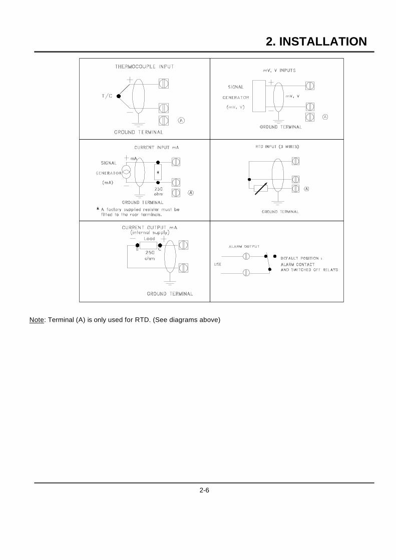
Note: Terminal (A) is only used for RTD. (See diagrams above)
2-6
2. INSTALLATION
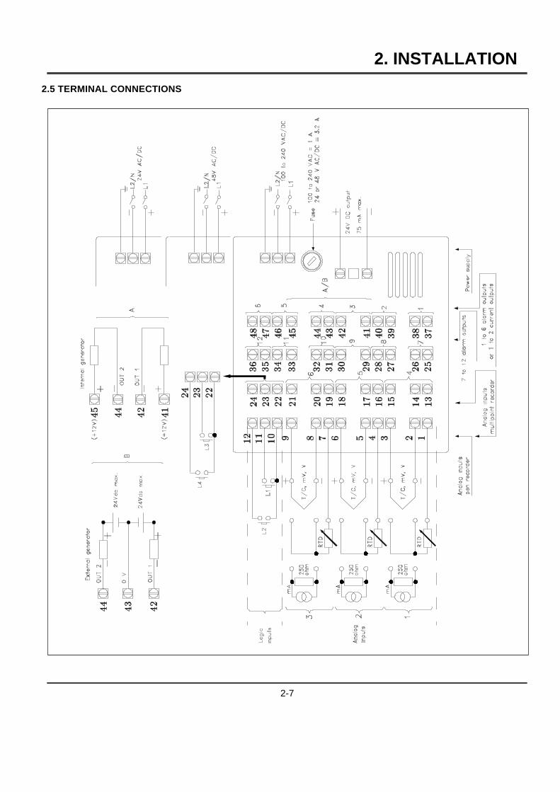
2.5 TERMINAL CONNECTIONS
2-7

2. INSTALLATION
2.6 FITTING THE CHART
2.6.1 Roll chart
Open the chart cassette as shown below and install the chart using the figure on the cassette.
Note 1: To maintain print quality, the print carriage guide rods should be cleaned at six-monthly intervals with adry cotton cloth. Lubricant should NOT be used.If required, the chart cassette can be cleaned with a damp cotton cloth.
Note 2: After the installation of a new chart, close the display and reinsert the chart cassette.
WARNING: Reset the paper length if configured after installing the new chart. See paragraph 3.2.1 "Operatorskeys".
2-8
2. INSTALLATION
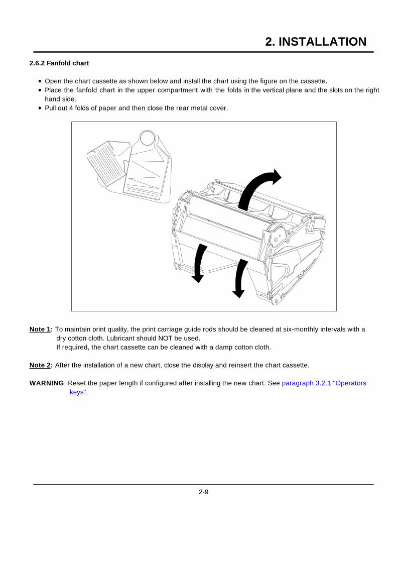
2.6.2 Fanfold chart
1 Open the chart cassette as shown below and install the chart using the figure on the cassette.1 Place the fanfold chart in the upper compartment with the folds in the vertical plane and the slots on the right
hand side.1 Pull out 4 folds of paper and then close the rear metal cover.
Note 1: To maintain print quality, the print carriage guide rods should be cleaned at six-monthly intervals with adry cotton cloth. Lubricant should NOT be used.If required, the chart cassette can be cleaned with a damp cotton cloth.
Note 2: After the installation of a new chart, close the display and reinsert the chart cassette.
WARNING: Reset the paper length if configured after installing the new chart. See paragraph 3.2.1 "Operatorskeys".
2-9
2. INSTALLATION
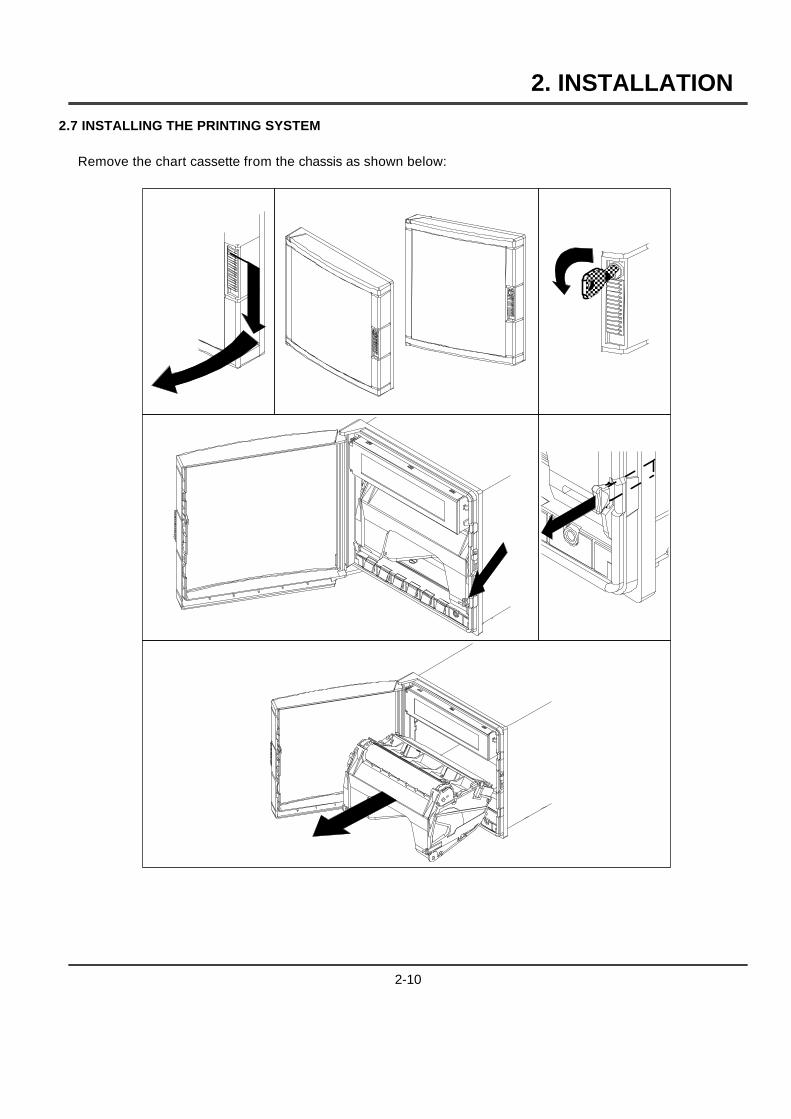
2.7 INSTALLING THE PRINTING SYSTEM
Remove the chart cassette from the chassis as shown below:
���
��� ����
2-10
2. INSTALLATION
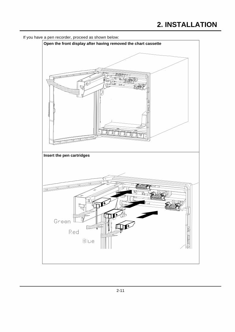
If you have a pen recorder, proceed as shown below:
Open the front display after having removed the chart cassette
������
������
������
������
������
������
������
������
������
������
������
Insert the pen cartridges
���
���
���
���
���
���
���
���
���
���
���
���
���
���
���
���
���
���
���
���
���
���
���
���
2-11
2. INSTALLATION
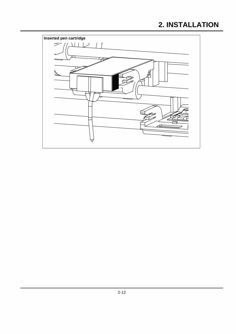
Inserted pen cartridge
2-12
2. INSTALLATION
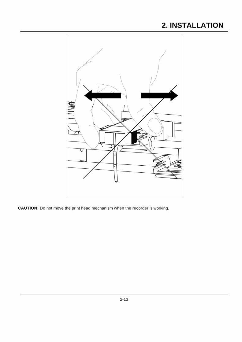
CAUTION: Do not move the print head mechanism when the recorder is working.
2-13
2. INSTALLATION
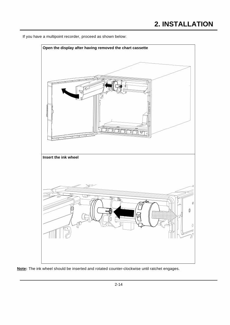
If you have a multipoint recorder, proceed as shown below:
Open the display after having removed the chart cassette
Insert the ink wheel
�����
�����
�����
�����
�����
�����
�����
�����
�����
Note: The ink wheel should be inserted and rotated counter-clockwise until ratchet engages.
2-14
2. INSTALLATION
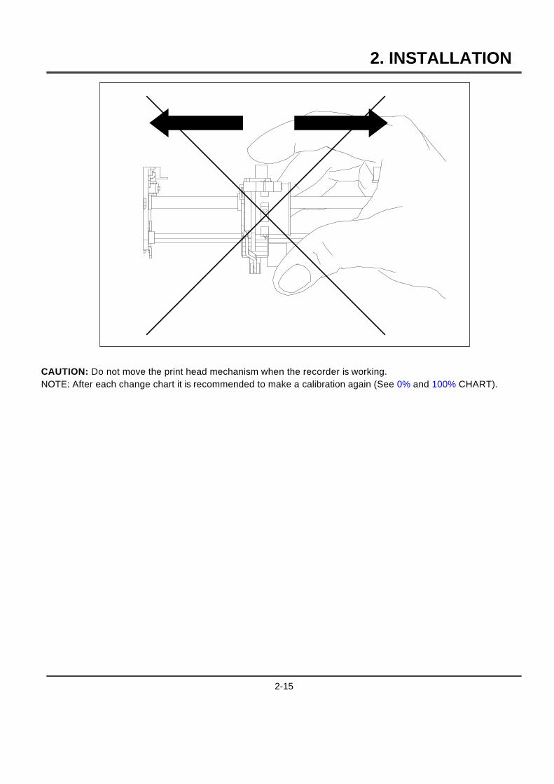
CAUTION: Do not move the print head mechanism when the recorder is working.NOTE: After each change chart it is recommended to make a calibration again (See 0% and 100% CHART).
2-15

2. INSTALLATION
FUNCTION TYPE OF SERVICE
PRINTER 0% CHART
DEFINITION : Chart certification to show the current 0% chart position with 0% print carriage.This is a mechanical adjustment.
HOW TO USE/EXECUTE IT : The message "(channel nb) CAL 0%" with a flashing number. This numbercorresponds to the present adjustment (= step motor).
To move to the right, increase this number or to the left, decrease the number.(You may introduce a negative number.)
You can change the distance value by pressing the[ ] keys.
You accept the value by pressingAYB .
You can leave the 0% chart service by pressingAZB
NOTE :When you pressAYB , the head moves and prints at the new 0% chartcalibration.
2-16

2. INSTALLATION
FUNCTION TYPE OF SERVICE
PRINTER 100% CHT
DEFINITION : Chart certification to show the current 100% chart position with 100% printcarriage.This is a mechanical adjustment.
HOW TO USE/EXECUTE IT : The message "(channel nb) CAL 100%" with a flashing number. This numbercorresponds to the present adjustment (= step motor).
To move to the right, increase this number or to the left, decrease the number.(You may introduce a negative number.)
You can change the distance value by pressing the[ ] keys.
You accept the value by pressingAYB .
You can leave the 100% chart service by pressingAZB
NOTE :When you pressAYB , the head moves and prints at the new 100%chart calibration.
2-17

2. INSTALLATION
2.8 CHECK LIST
Have you connected the ground terminal ?1
Have you connected the sensor(s) correctly ? (Wire type, polarity, etc)2
Have you tightened all terminal screws ?3
Have you installed the ink cartridge(s) or wheel ?(See figures on pages 2-11 to 2-15)4
Have you installed the chart correctly ?(See figures on pages 2-8 and 2-9)5
Have you closed the display ?6
Have you fitted the chart cassette in the recorder ?7
2-18

3. OPERATION
3.1 OPERATOR INTERFACE EXPLANATION
The operator interface comprises the display and keypad.
DISPLAY
The display gives a clear indication of action prompts by means of one line of 12 characters.
KEYPAD
The keypad consists of 6 keys :
2 TheAZBkey allows you to escape from any action menu and return to normal operating mode.
2[ allows you to HOLD or SCAN the channel display.
2] allows you to select the DISPLAY TYPE desired.
2{ allows you to select the PRINT action desired.
2} allows you to select the MATH or BATCH action desired.
2 TheAYBkey allows you to confirm your selected action.
3-1
3. OPERATION
3.2 BASIC ACTIONS
Basic actions are executed by using the [ ] { } keys without entering the configuration mode. Noconfiguration parameter can be modified.
NOTE :
The [ ] { keys are enabled and the} key is disabled by the default
factory configuration. See MMI sub-matrix in the "CONFIGURATION" chapter to
modify the actions above.
.
3.2.1 Operators keys
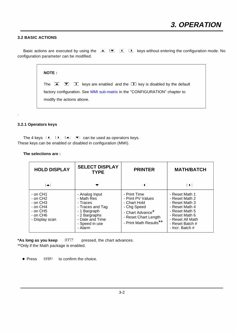
The 4 keys { } [ ] can be used as operators keys.These keys can be enabled or disabled in configuration (MMI).
The selections are :
HOLD DISPLAY SELECT DISPLAYTYPE PRINTER MATH/BATCH
[ ] { }- on CH1- on CH2- on CH3- on CH4- on CH5- on CH6- Display scan
- Analog Input- Math Res- Traces- Traces and Tag- 1 Bargraph- 2 Bargraphs- Date and Time- Speed in use- Alarm
- Print Time- Print PV Values- Chart Hold- Chg Speed- Chart Advance*- Reset Chart Length- Print Math Results**
- Reset Math 1- Reset Math 2- Reset Math 3- Reset Math 4- Reset Math 5- Reset Math 6- Reset All Math- Reset Batch #- Incr. Batch #
*As long as you keepAYB pressed, the chart advances.**Only if the Math package is enabled.
2 PressAYBto confirm the choice.
3-2
3. OPERATION
3.2.2 How to select the display type
Ten display types are available :
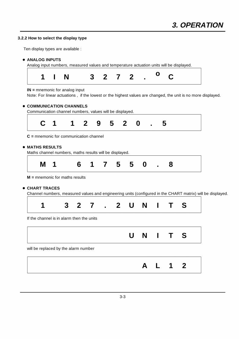
2 ANALOG INPUTSAnalog input numbers, measured values and temperature actuation units will be displayed.
1 I N 3 2 7 2 . o C
IN = mnemonic for analog inputNote: For linear actuations , if the lowest or the highest values are changed, the unit is no more displayed.
2 COMMUNICATION CHANNELSCommunication channel numbers, values will be displayed.
C 1 1 2 9 5 2 0 . 5
C = mnemonic for communication channel
2 MATHS RESULTSMaths channel numbers, maths results will be displayed.
M 1 6 1 7 5 5 0 . 8
M = mnemonic for maths results
2 CHART TRACESChannel numbers, measured values and engineering units (configured in the CHART matrix) will be displayed.
1 3 2 7 . 2 U N I T S
If the channel is in alarm then the units
U N I T S
will be replaced by the alarm number
A L 1 2
3-3
3. OPERATION
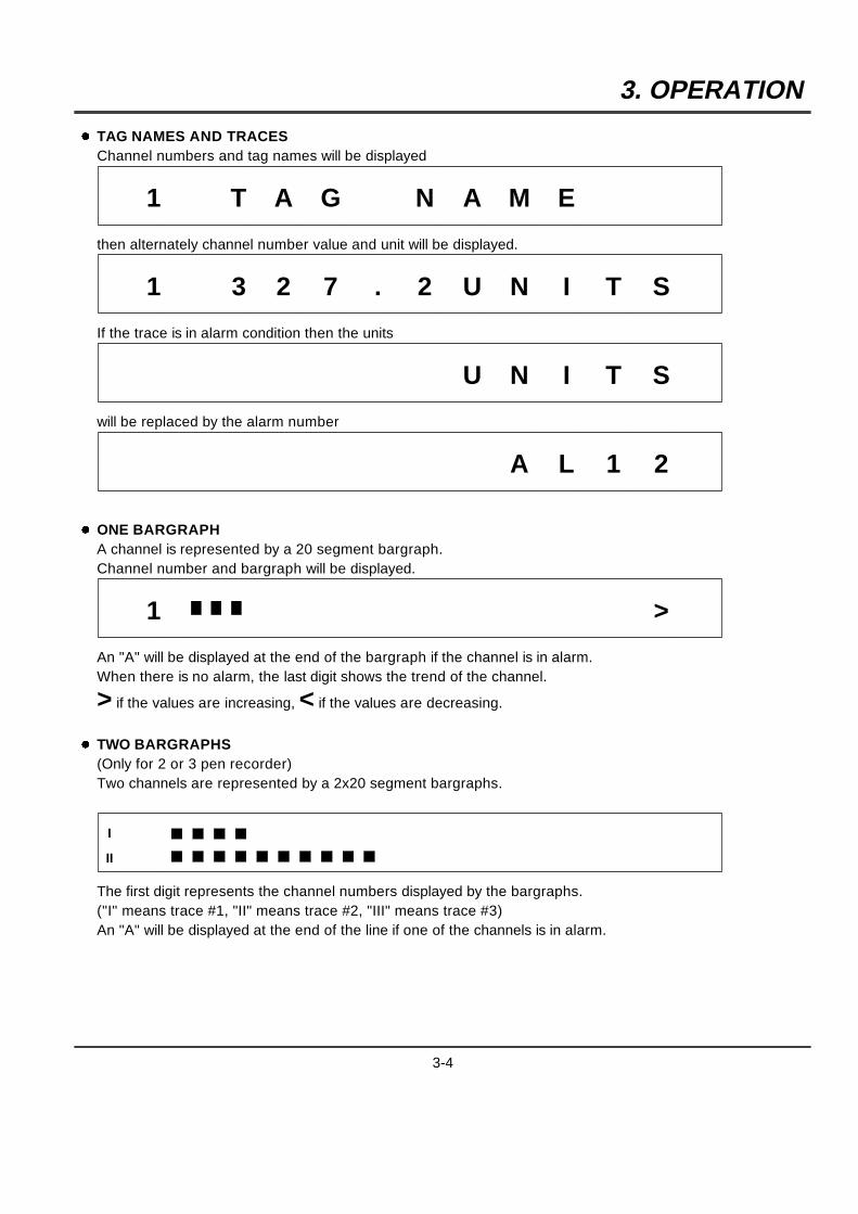
2 TAG NAMES AND TRACESChannel numbers and tag names will be displayed
1 T A G N A M E
then alternately channel number value and unit will be displayed.
1 3 2 7 . 2 U N I T S
If the trace is in alarm condition then the units
U N I T S
will be replaced by the alarm number
A L 1 2
2 ONE BARGRAPHA channel is represented by a 20 segment bargraph.Channel number and bargraph will be displayed.
1 >
An "A" will be displayed at the end of the bargraph if the channel is in alarm.When there is no alarm, the last digit shows the trend of the channel.
> if the values are increasing, < if the values are decreasing.
2 TWO BARGRAPHS(Only for 2 or 3 pen recorder)Two channels are represented by a 2x20 segment bargraphs.
I
II
The first digit represents the channel numbers displayed by the bargraphs.("I" means trace #1, "II" means trace #2, "III" means trace #3)An "A" will be displayed at the end of the line if one of the channels is in alarm.
3-4
3. OPERATION
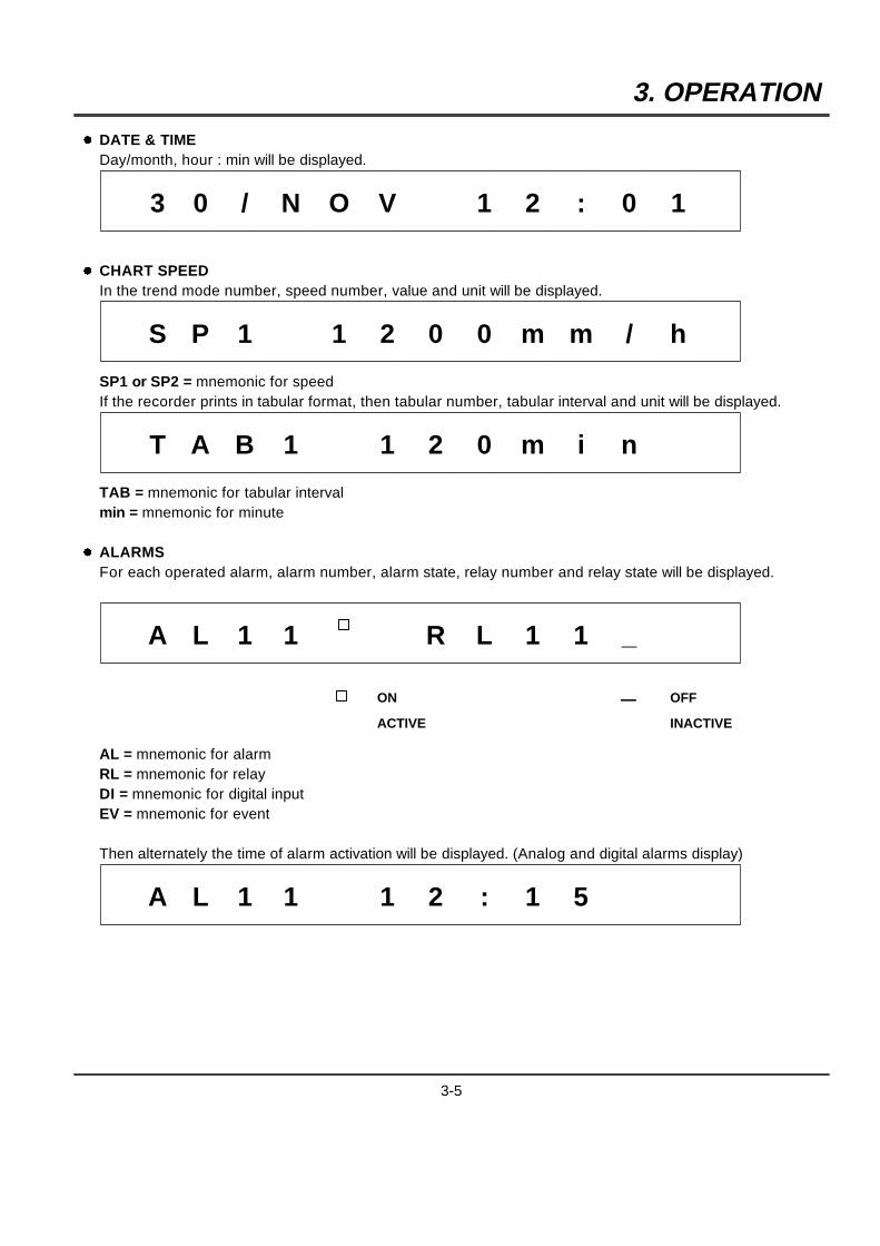
2 DATE & TIMEDay/month, hour : min will be displayed.
3 0 / N O V 1 2 : 0 1
2 CHART SPEEDIn the trend mode number, speed number, value and unit will be displayed.
S P 1 1 2 0 0 m m / h
SP1 or SP2 = mnemonic for speedIf the recorder prints in tabular format, then tabular number, tabular interval and unit will be displayed.
T A B 1 1 2 0 m i n
TAB = mnemonic for tabular intervalmin = mnemonic for minute
2 ALARMSFor each operated alarm, alarm number, alarm state, relay number and relay state will be displayed.
A L 1 1 R L 1 1 _
ON
ACTIVE
_ OFF
INACTIVE
AL = mnemonic for alarmRL = mnemonic for relayDI = mnemonic for digital inputEV = mnemonic for event
Then alternately the time of alarm activation will be displayed. (Analog and digital alarms display)
A L 1 1 1 2 : 1 5
3-5

3. OPERATION
3-6
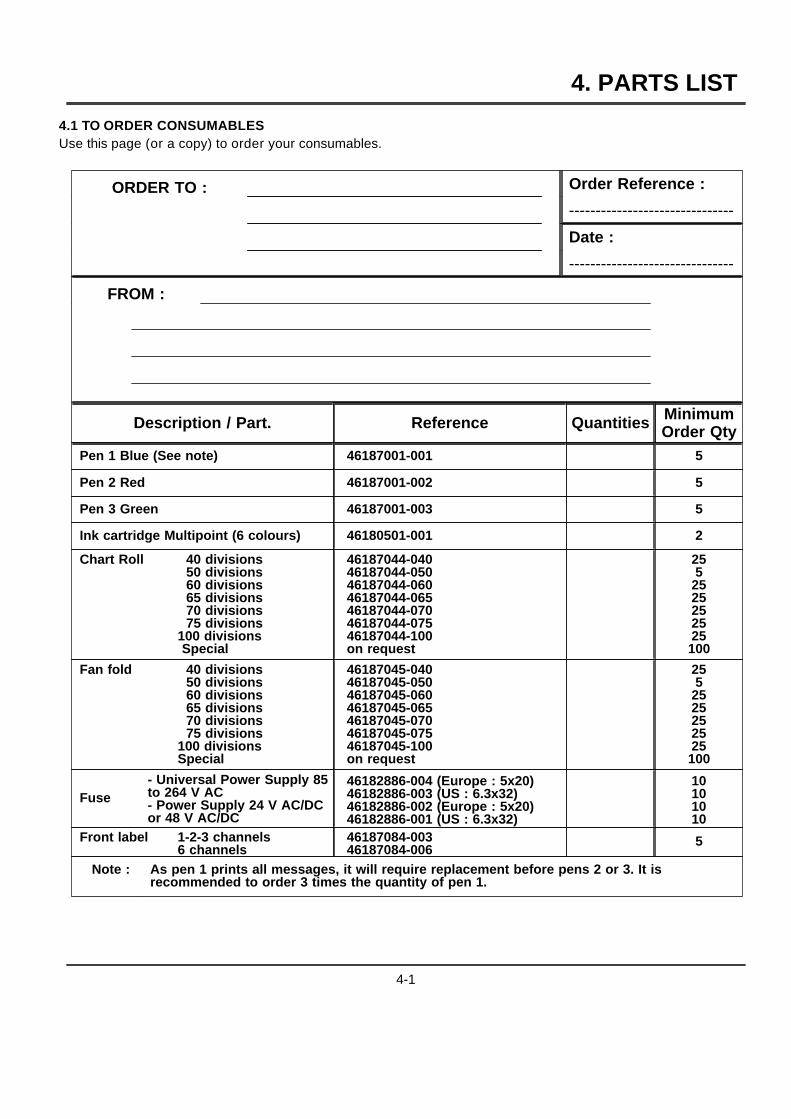
4. PARTS LIST
4.1 TO ORDER CONSUMABLESUse this page (or a copy) to order your consumables.
ORDER TO : Order Reference :
-------------------------------
Date :
-------------------------------
FROM :
Description / Part. Reference Quantities MinimumOrder Qty
Pen 1 Blue (See note) 46187001-001 5
Pen 2 Red 46187001-002 5
Pen 3 Green 46187001-003 5
Ink cartridge Multipoint (6 colours) 46180501-001 2
Chart Roll 40 divisions50 divisions60 divisions65 divisions70 divisions75 divisions
100 divisionsSpecial
46187044-04046187044-05046187044-06046187044-06546187044-07046187044-07546187044-100on request
255
2525252525100
Fan fold 40 divisions50 divisions60 divisions65 divisions70 divisions75 divisions
100 divisionsSpecial
46187045-04046187045-05046187045-06046187045-06546187045-07046187045-07546187045-100on request
255
2525252525100
Fuse- Universal Power Supply 85to 264 V AC- Power Supply 24 V AC/DCor 48 V AC/DC
46182886-004 (Europe : 5x20)46182886-003 (US : 6.3x32)46182886-002 (Europe : 5x20)46182886-001 (US : 6.3x32)
10101010
Front label 1-2-3 channels6 channels
46187084-00346187084-006
5
Note : As pen 1 prints all messages, it will require replacement before pens 2 or 3. It isrecommended to order 3 times the quantity of pen 1.
4-1

4. PARTS LIST
4-2
5. MODEL SELECTION GUIDE
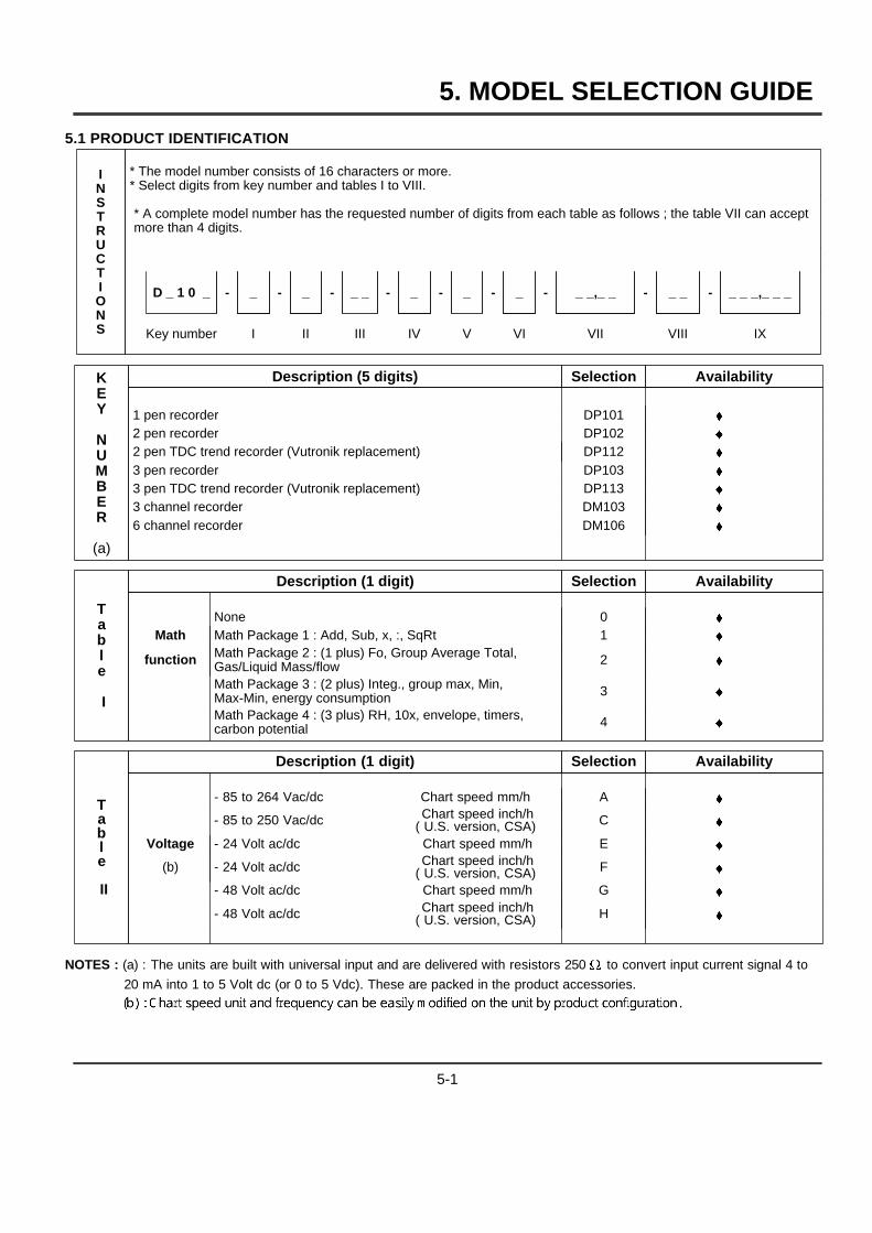
5.1 PRODUCT IDENTIFICATION
INSTRUCTIONS
* The model number consists of 16 characters or more.* Select digits from key number and tables I to VIII.
* A complete model number has the requested number of digits from each table as follows ; the table VII can acceptmore than 4 digits.
D _ 1 0 _ - _ - _ - _ _ - _ - _ - _ - _ _,_ _ - _ _ - _ _ _,_ _ _
Key number I II III IV V VI VII VIII IX
KEY
NUMBER
(a)
Description (5 digits) Selection Availability
1 pen recorder DP101 }2 pen recorder DP102 }2 pen TDC trend recorder (Vutronik replacement) DP112 }3 pen recorder DP103 }3 pen TDC trend recorder (Vutronik replacement) DP113 }3 channel recorder DM103 }6 channel recorder DM106 }
Table
I
Description (1 digit) Selection Availability
None 0 }Math Math Package 1 : Add, Sub, x, :, SqRt 1 }
function Math Package 2 : (1 plus) Fo, Group Average Total,Gas/Liquid Mass/flow 2 }
Math Package 3 : (2 plus) Integ., group max, Min,Max-Min, energy consumption 3 }
Math Package 4 : (3 plus) RH, 10x, envelope, timers,carbon potential 4 }
Table
II
Description (1 digit) Selection Availability
- 85 to 264 Vac/dc Chart speed mm/h A }
- 85 to 250 Vac/dc Chart speed inch/h( U.S. version, CSA) C }
Voltage - 24 Volt ac/dc Chart speed mm/h E }
(b) - 24 Volt ac/dc Chart speed inch/h( U.S. version, CSA) F }
- 48 Volt ac/dc Chart speed mm/h G }
- 48 Volt ac/dc Chart speed inch/h( U.S. version, CSA) H }
NOTES : (a) : The units are built with universal input and are delivered with resistors 250 W to convert input current signal 4 to
20 mA into 1 to 5 Volt dc (or 0 to 5 Vdc). These are packed in the product accessories.
5-1
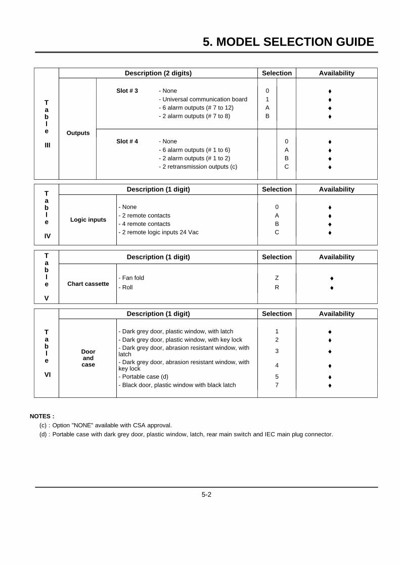
5. MODEL SELECTION GUIDE
Table
III
Description (2 digits) Selection Availability
Slot # 3 - None 0 }- Universal communication board 1 }- 6 alarm outputs (# 7 to 12) A }- 2 alarm outputs (# 7 to 8) B }
OutputsSlot # 4 - None 0 }
- 6 alarm outputs (# 1 to 6) A }- 2 alarm outputs (# 1 to 2) B }- 2 retransmission outputs (c) C }
Table
IV
Description (1 digit) Selection Availability
Logic inputs
- None 0 }- 2 remote contacts A }- 4 remote contacts B }- 2 remote logic inputs 24 Vac C }
Table
V
Description (1 digit) Selection Availability
Chart cassette- Fan fold Z }- Roll R }
Table
VI
Description (1 digit) Selection Availability
Doorandcase
- Dark grey door, plastic window, with latch 1 }- Dark grey door, plastic window, with key lock 2 }- Dark grey door, abrasion resistant window, withlatch 3 }
- Dark grey door, abrasion resistant window, withkey lock 4 }
- Portable case (d) 5 }- Black door, plastic window with black latch 7 }
NOTES :
(c) : Option "NONE" available with CSA approval.
(d) : Portable case with dark grey door, plastic window, latch, rear main switch and IEC main plug connector.
5-2
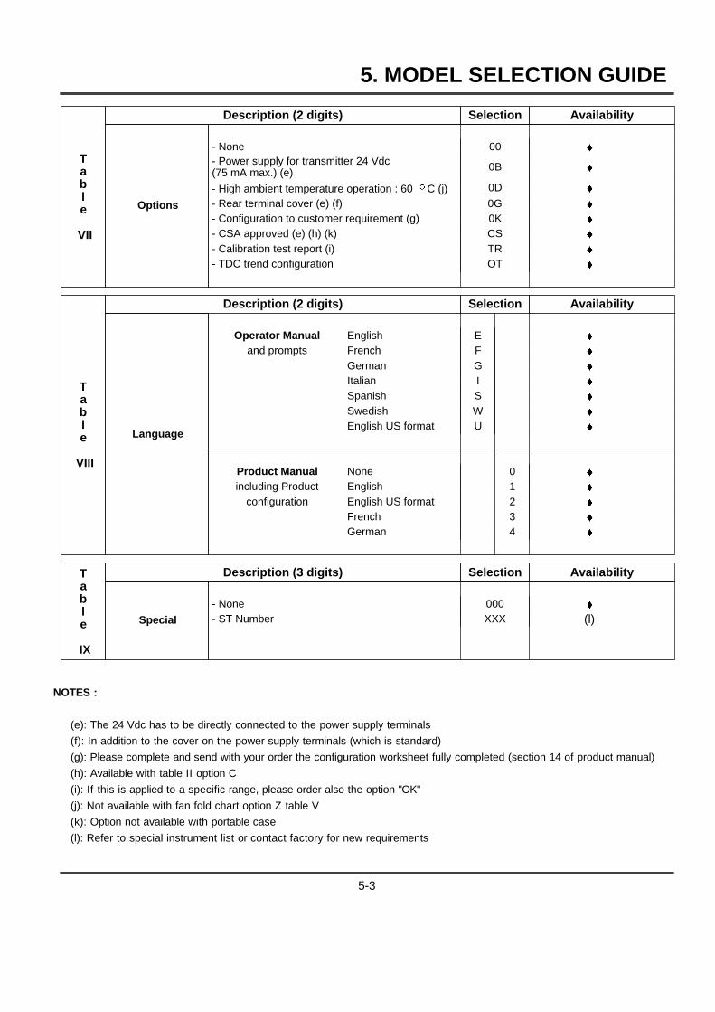
5. MODEL SELECTION GUIDE
Table
VII
Description (2 digits) Selection Availability
Options
- None 00 }- Power supply for transmitter 24 Vdc(75 mA max.) (e) 0B }
- High ambient temperature operation : 60 oC (j) 0D }- Rear terminal cover (e) (f) 0G }- Configuration to customer requirement (g) 0K }- CSA approved (e) (h) (k) CS }- Calibration test report (i) TR }- TDC trend configuration OT }
Table
VIII
Description (2 digits) Selection Availability
Language
Operator Manual English E }and prompts French F }
German G }Italian I }Spanish S }Swedish W }English US format U }
Product Manual None 0 }including Product English 1 }
configuration English US format 2 }French 3 }German 4 }
Table
IX
Description (3 digits) Selection Availability
Special
- None 000 }- ST Number XXX (l)
NOTES :
(e): The 24 Vdc has to be directly connected to the power supply terminals
(f): In addition to the cover on the power supply terminals (which is standard)
(g): Please complete and send with your order the configuration worksheet fully completed (section 14 of product manual)
(h): Available with table II option C
(i): If this is applied to a specific range, please order also the option "OK"
(j): Not available with fan fold chart option Z table V
(k): Option not available with portable case
(l): Refer to special instrument list or contact factory for new requirements
5-3

5. MODEL SELECTION GUIDE
5-4
6. PRODUCT SPECIFICATION SHEET
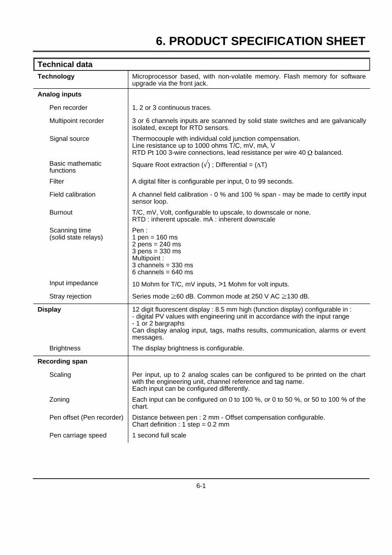
Technical dataTechnology Microprocessor based, with non-volatile memory. Flash memory for software
upgrade via the front jack.
Analog inputs
Pen recorder 1, 2 or 3 continuous traces.
Multipoint recorder 3 or 6 channels inputs are scanned by solid state switches and are galvanicallyisolated, except for RTD sensors.
Signal source Thermocouple with individual cold junction compensation.Line resistance up to 1000 ohms T/C, mV, mA, VRTD Pt 100 3-wire connections, lead resistance per wire 40 W balanced.
Basic mathematicfunctions
Square Root extraction (i) ; Differential = (DT)
Filter A digital filter is configurable per input, 0 to 99 seconds.
Field calibration A channel field calibration - 0 % and 100 % span - may be made to certify inputsensor loop.
Burnout T/C, mV, Volt, configurable to upscale, to downscale or none.RTD : inherent upscale. mA : inherent downscale
Scanning time(solid state relays)
Pen :1 pen = 160 ms2 pens = 240 ms3 pens = 330 msMultipoint :3 channels = 330 ms6 channels = 640 ms
Input impedance 10 Mohm for T/C, mV inputs, >1 Mohm for volt inputs.
Stray rejection Series mode .60 dB. Common mode at 250 V AC .130 dB.
Display 12 digit fluorescent display : 8.5 mm high (function display) configurable in :- digital PV values with engineering unit in accordance with the input range- 1 or 2 bargraphsCan display analog input, tags, maths results, communication, alarms or eventmessages.
Brightness The display brightness is configurable.
Recording span
Scaling Per input, up to 2 analog scales can be configured to be printed on the chartwith the engineering unit, channel reference and tag name.Each input can be configured differently.
Zoning Each input can be configured on 0 to 100 %, or 0 to 50 %, or 50 to 100 % of thechart.
Pen offset (Pen recorder) Distance between pen : 2 mm - Offset compensation configurable.Chart definition : 1 step = 0.2 mm
Pen carriage speed 1 second full scale
6-1
6. PRODUCT SPECIFICATION SHEET
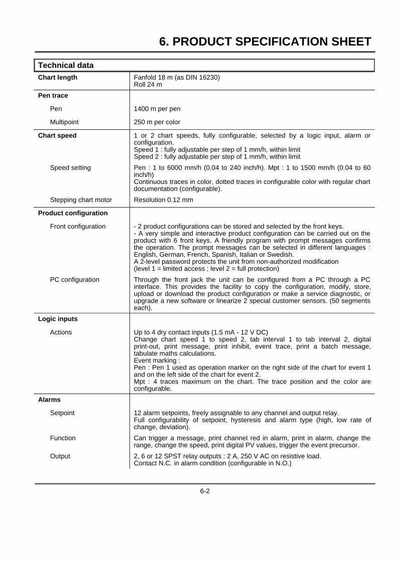
Technical dataChart length Fanfold 18 m (as DIN 16230)
Roll 24 m
Pen trace
Pen 1400 m per pen
Multipoint 250 m per color
Chart speed 1 or 2 chart speeds, fully configurable, selected by a logic input, alarm orconfiguration.Speed 1 : fully adjustable per step of 1 mm/h, within limitSpeed 2 : fully adjustable per step of 1 mm/h, within limit
Speed setting Pen : 1 to 6000 mm/h (0.04 to 240 inch/h). Mpt : 1 to 1500 mm/h (0.04 to 60inch/h)Continuous traces in color, dotted traces in configurable color with regular chartdocumentation (configurable).
Stepping chart motor Resolution 0.12 mm
Product configuration
Front configuration - 2 product configurations can be stored and selected by the front keys.- A very simple and interactive product configuration can be carried out on theproduct with 6 front keys. A friendly program with prompt messages confirmsthe operation. The prompt messages can be selected in different languages :English, German, French, Spanish, Italian or Swedish.A 2-level password protects the unit from non-authorized modification(level 1 = limited access ; level 2 = full protection)
PC configuration Through the front jack the unit can be configured from a PC through a PCinterface. This provides the facility to copy the configuration, modify, store,upload or download the product configuration or make a service diagnostic, orupgrade a new software or linearize 2 special customer sensors. (50 segmentseach).
Logic inputs
Actions Up to 4 dry contact inputs (1.5 mA - 12 V DC)Change chart speed 1 to speed 2, tab interval 1 to tab interval 2, digitalprint-out, print message, print inhibit, event trace, print a batch message,tabulate maths calculations.Event marking :Pen : Pen 1 used as operation marker on the right side of the chart for event 1and on the left side of the chart for event 2.Mpt : 4 traces maximum on the chart. The trace position and the color areconfigurable.
Alarms
Setpoint 12 alarm setpoints, freely assignable to any channel and output relay.Full configurability of setpoint, hysteresis and alarm type (high, low rate ofchange, deviation).
Function Can trigger a message, print channel red in alarm, print in alarm, change therange, change the speed, print digital PV values, trigger the event precursor.
Output 2, 6 or 12 SPST relay outputs : 2 A, 250 V AC on resistive load.Contact N.C. in alarm condition (configurable in N.O.)
6-2

6. PRODUCT SPECIFICATION SHEET
Technical dataAlphanumeric documentation
Messages 12 freely assignable and configurable messages of 14 characters each,including the specific German and Swedish letters.Can be printed with the date/time on top of the traces by alarms, logic inputs orcommunication.
Batch header One batch message of 4 lines of 14 characters, fully configurable, withincremented batch numbers and date/time. Printed through digital input andsaved upon power interruption.
Process variable The traces can be assigned to analog input, mathematics calculations orcommunication inputs, and are printed in channel color. Periodic digital printingat time intervals configurable from 1 to 1440 minutes. Digital print-out of PVvalues through alarms, digital inputs, communication or front keyboard.
Tag name Each channel can be named by 8 characters.
Event precursor
Stand-by The acquisition data is stored in a buffer memory. (FiFo)A stand-by message is periodically printed.
Downloading On event (alarm, digital input, front key, communication) the data is downloadedto be printed on the chart at pre-configured speed.The history before and after the event represents about 50 mm of chart paper.
Mathematics package(optional)
Many functions are available such as :- Basic mathematics functions- Square root- Fo sterilization- Totalization- Mass flows- Energy consumption- Vacuum pressure- Averages- Min., max.- Timers- Carbon potentialThe maths calculations and results are stored during power interruptions.
Digital communication(optional)
Protocols RS232 ASCII communication to PC application. RS422 or RS485 ASCIIcommunication output. RS422 or RS485 Modbus RTU communication output.
PC supervision Through ASCII communication, application software gives the facility to readPV's, alarms or event status, to store the information on a file, to send amessage to the recorder or to modify the product configuration.
Autodial The RS232 ASCII communication can dial automatically a phone number of aremote station to send via modem an alarm message or a periodic report.
Event The recorder can be configured to deliver an output signal (alarm relay) on arecorder event such as burnout, paper cassette out, battery fail, alarm condition,communication interrupted.
6-3
6. PRODUCT SPECIFICATION SHEET
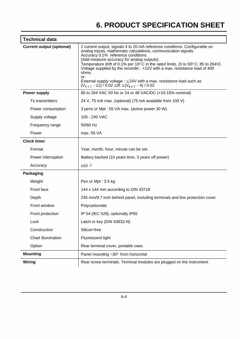
Technical dataCurrent output (optional) 2 current output, signals 4 to 20 mA reference conditions. Configurable on
analog inputs, mathematic calculations, communication signals.Accuracy 0.1% reference conditions.(Add measure accuracy for analog outputs).Temperature drift of 0.1% per 10oC in the rated limits. (0 to 50oC; 85 to 264V).Voltage supplied by the recorder : +12V with a max. resistance load of 400ohms.orExternal supply voltage : ,24V with a max. resistance load such as(Vext
- 12) / 0.02 ,R ,(Vext
- 4) / 0.02
Power supply 85 to 264 VAC 50 Hz or 24 or 48 VAC/DC (+10-15% nominal)
To transmitters 24 V, 75 mA max. (optional) (75 mA available from 100 V)
Power consumption 3 pens or Mpt : 55 VA max. (active power 30 W).
Supply voltage 100 - 240 VAC
Frequency range 50/60 Hz
Power max. 55 VA
Clock timer
Format Year, month, hour, minute can be set.
Power interruption Battery backed (10 years time, 3 years off power)
Accuracy &10 -5
Packaging
Weight Pen or Mpt : 3.5 kg
Front face 144 x 144 mm according to DIN 43718
Depth 245 mm/9.7 inch behind panel, including terminals and line protection cover
Front window Polycarbonate
Front protection IP 54 (IEC 529), optionally IP55
Lock Latch or key (DIN 43832-N)
Construction Silicon-free
Chart illumination Fluorescent light
Option Rear terminal cover, portable case.
Mounting Panel mounting &30o from horizontal
Wiring Rear screw terminals. Terminal modules are plugged on the instrument.
6-4
6. PRODUCT SPECIFICATION SHEET
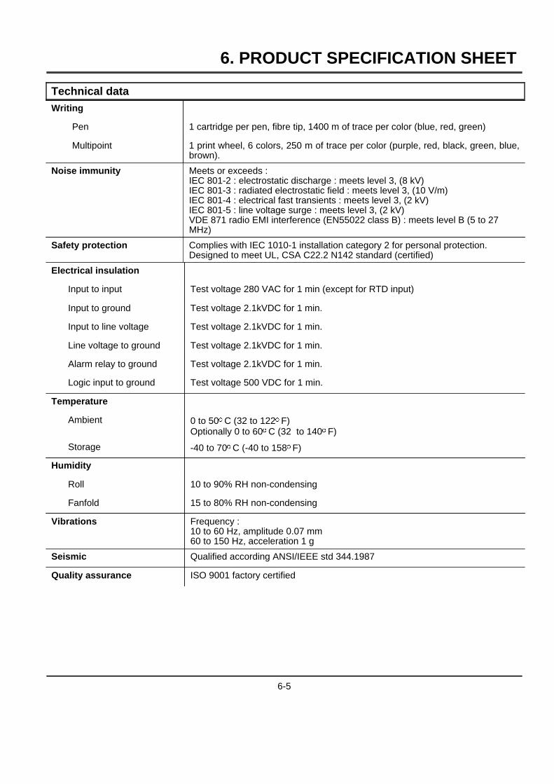
Technical dataWriting
Pen 1 cartridge per pen, fibre tip, 1400 m of trace per color (blue, red, green)
Multipoint 1 print wheel, 6 colors, 250 m of trace per color (purple, red, black, green, blue,brown).
Noise immunity Meets or exceeds :IEC 801-2 : electrostatic discharge : meets level 3, (8 kV)IEC 801-3 : radiated electrostatic field : meets level 3, (10 V/m)IEC 801-4 : electrical fast transients : meets level 3, (2 kV)IEC 801-5 : line voltage surge : meets level 3, (2 kV)VDE 871 radio EMI interference (EN55022 class B) : meets level B (5 to 27MHz)
Safety protection Complies with IEC 1010-1 installation category 2 for personal protection.Designed to meet UL, CSA C22.2 N142 standard (certified)
Electrical insulation
Input to input Test voltage 280 VAC for 1 min (except for RTD input)
Input to ground Test voltage 2.1kVDC for 1 min.
Input to line voltage Test voltage 2.1kVDC for 1 min.
Line voltage to ground Test voltage 2.1kVDC for 1 min.
Alarm relay to ground Test voltage 2.1kVDC for 1 min.
Logic input to ground Test voltage 500 VDC for 1 min.
Temperature
Ambient 0 to 50oC (32 to 122oF)Optionally 0 to 60oC (32 to 140oF)
Storage -40 to 70oC (-40 to 158oF)
Humidity
Roll 10 to 90% RH non-condensing
Fanfold 15 to 80% RH non-condensing
Vibrations Frequency :10 to 60 Hz, amplitude 0.07 mm60 to 150 Hz, acceleration 1 g
Seismic Qualified according ANSI/IEEE std 344.1987
Quality assurance ISO 9001 factory certified
6-5
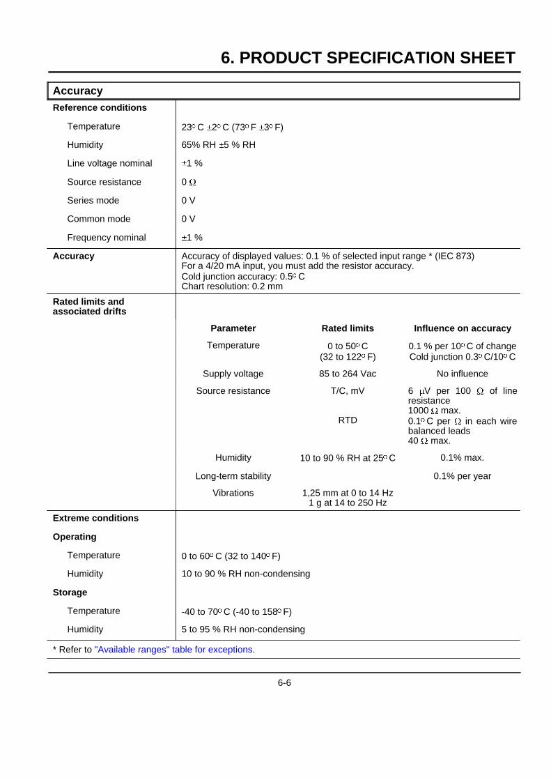
6. PRODUCT SPECIFICATION SHEET
AccuracyReference conditions
Temperature 23oC &2oC (73oF &3oF)
Humidity 65% RH &5 % RH
Line voltage nominal &1 %
Source resistance 0 W
Series mode 0 V
Common mode 0 V
Frequency nominal &1 %
Accuracy Accuracy of displayed values: 0.1 % of selected input range * (IEC 873)For a 4/20 mA input, you must add the resistor accuracy.Cold junction accuracy: 0.5oCChart resolution: 0.2 mm
Rated limits andassociated drifts
Parameter Rated limits Influence on accuracy
Temperature 0 to 50oC(32 to 122oF)
0.1 % per 10oC of changeCold junction 0.3oC/10oC
Supply voltage 85 to 264 Vac No influence
Source resistance T/C, mV
RTD
6 mV per 100 W of lineresistance1000 W max.0.1oC per W in each wirebalanced leads40 W max.
Humidity 10 to 90 % RH at 25oC 0.1% max.
Long-term stability 0.1% per year
Vibrations 1,25 mm at 0 to 14 Hz1 g at 14 to 250 Hz
Extreme conditions
Operating
Temperature 0 to 60oC (32 to 140oF)
Humidity 10 to 90 % RH non-condensing
Storage
Temperature -40 to 70oC (-40 to 158oF)
Humidity 5 to 95 % RH non-condensing
* Refer to "Available ranges" table for exceptions.
6-6
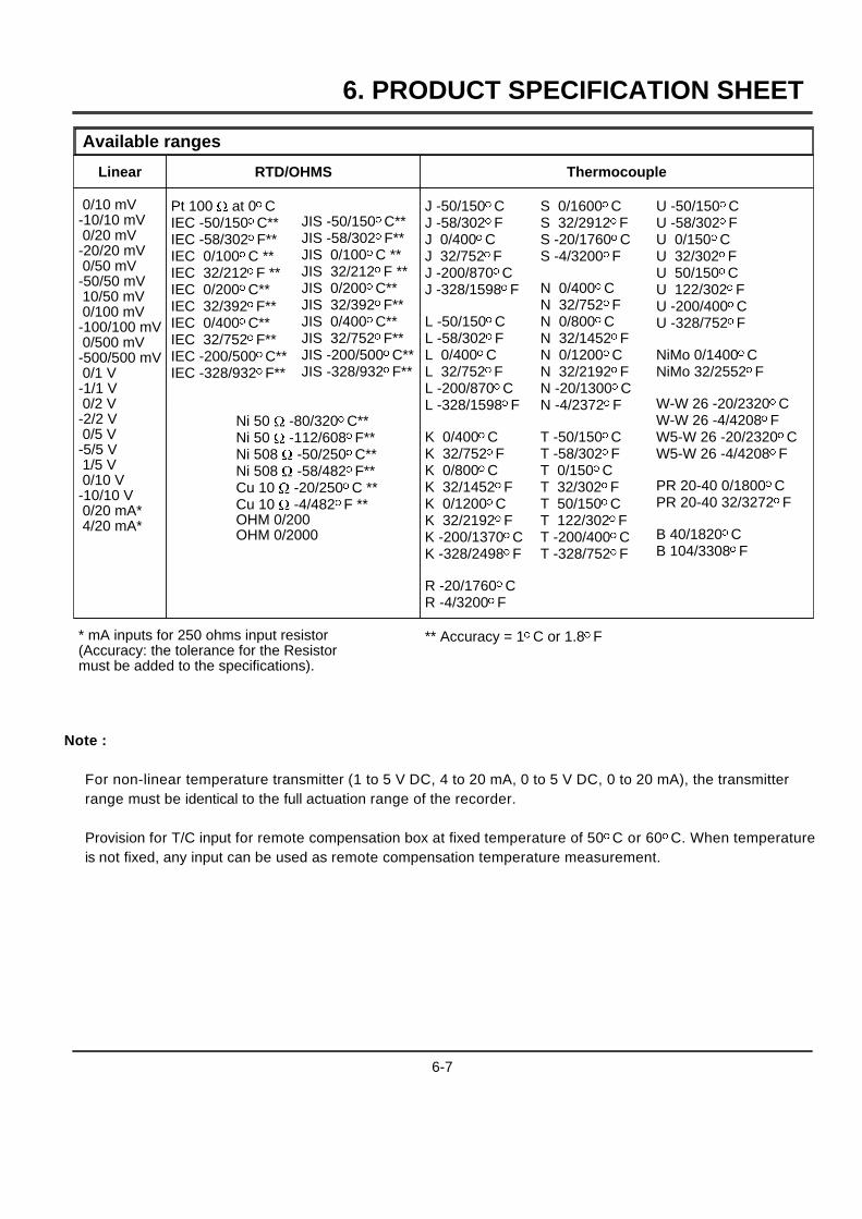
6. PRODUCT SPECIFICATION SHEET
Available ranges
Linear RTD/OHMS Thermocouple
0/10 mV-10/10 mV0/20 mV
-20/20 mV0/50 mV
-50/50 mV10/50 mV0/100 mV
-100/100 mV0/500 mV
-500/500 mV0/1 V
-1/1 V0/2 V
-2/2 V0/5 V
-5/5 V1/5 V0/10 V
-10/10 V0/20 mA*4/20 mA*
Pt 100 W at 0oCIEC -50/150oC**IEC -58/302oF**IEC 0/100oC **IEC 32/212oF **IEC 0/200oC**IEC 32/392oF**IEC 0/400oC**IEC 32/752oF**IEC -200/500oC**IEC -328/932oF**
JIS -50/150oC**JIS -58/302oF**JIS 0/100oC **JIS 32/212oF **JIS 0/200oC**JIS 32/392oF**JIS 0/400oC**JIS 32/752oF**JIS -200/500oC**JIS -328/932oF**
J -50/150oCJ -58/302oFJ 0/400oCJ 32/752oFJ -200/870oCJ -328/1598oF
L -50/150oCL -58/302oFL 0/400oCL 32/752oFL -200/870oCL -328/1598oF
K 0/400oCK 32/752oFK 0/800oCK 32/1452oFK 0/1200oCK 32/2192oFK -200/1370oCK -328/2498oF
R -20/1760oCR -4/3200oF
S 0/1600oCS 32/2912oFS -20/1760oCS -4/3200oF
N 0/400oCN 32/752oFN 0/800oCN 32/1452oFN 0/1200oCN 32/2192oFN -20/1300oCN -4/2372oF
T -50/150oCT -58/302oFT 0/150oCT 32/302oFT 50/150oCT 122/302oFT -200/400oCT -328/752oF
U -50/150oCU -58/302oFU 0/150oCU 32/302oFU 50/150oCU 122/302oFU -200/400oCU -328/752oF
NiMo 0/1400oCNiMo 32/2552oF
W-W 26 -20/2320oCW-W 26 -4/4208oFW5-W 26 -20/2320oCW5-W 26 -4/4208oF
PR 20-40 0/1800oCPR 20-40 32/3272oF
B 40/1820oCB 104/3308oF
Ni 50 W -80/320oC**Ni 50 W -112/608oF**Ni 508 W -50/250oC**Ni 508 W -58/482oF**Cu 10 W -20/250oC **Cu 10 W -4/482oF **OHM 0/200OHM 0/2000
* mA inputs for 250 ohms input resistor(Accuracy: the tolerance for the Resistormust be added to the specifications).
** Accuracy = 1oC or 1.8oF
Note :
For non-linear temperature transmitter (1 to 5 V DC, 4 to 20 mA, 0 to 5 V DC, 0 to 20 mA), the transmitterrange must be identical to the full actuation range of the recorder.
Provision for T/C input for remote compensation box at fixed temperature of 50oC or 60oC. When temperatureis not fixed, any input can be used as remote compensation temperature measurement.
6-7

6. PRODUCT SPECIFICATION SHEET
6-8
7. CONFIGURATION
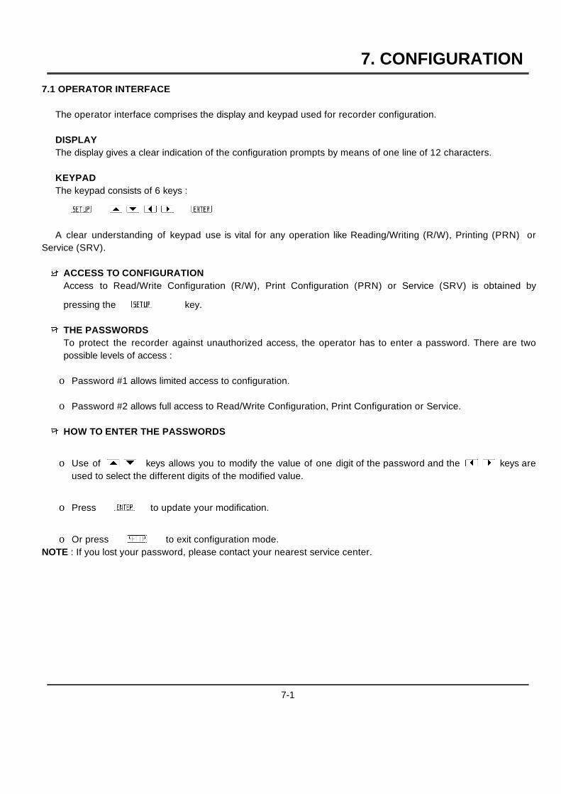
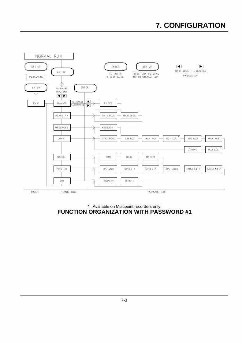
7.1 OPERATOR INTERFACE
The operator interface comprises the display and keypad used for recorder configuration.
DISPLAYThe display gives a clear indication of the configuration prompts by means of one line of 12 characters.
KEYPADThe keypad consists of 6 keys :
AZB[]{}AYB
A clear understanding of keypad use is vital for any operation like Reading/Writing (R/W), Printing (PRN) orService (SRV).
9 ACCESS TO CONFIGURATIONAccess to Read/Write Configuration (R/W), Print Configuration (PRN) or Service (SRV) is obtained by
pressing theAZB key.
9 THE PASSWORDSTo protect the recorder against unauthorized access, the operator has to enter a password. There are twopossible levels of access :
o Password #1 allows limited access to configuration.
o Password #2 allows full access to Read/Write Configuration, Print Configuration or Service.
9 HOW TO ENTER THE PASSWORDS
o Use of[] keys allows you to modify the value of one digit of the password and the{} keys areused to select the different digits of the modified value.
o PressAYBto update your modification.
o Or pressAZB to exit configuration mode.NOTE : If you lost your password, please contact your nearest service center.
7-1
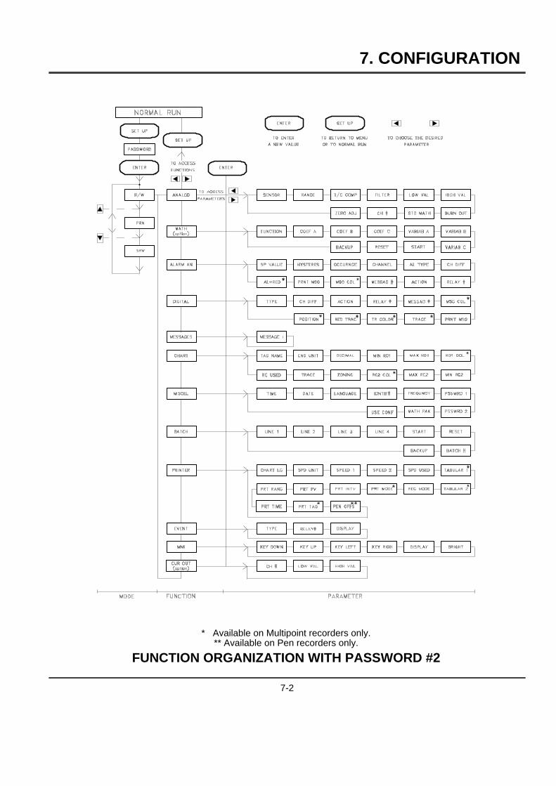
7. CONFIGURATION
* Available on Multipoint recorders only.** Available on Pen recorders only.
FUNCTION ORGANIZATION WITH PASSWORD #2
7-2
7. CONFIGURATION
* Available on Multipoint recorders only.FUNCTION ORGANIZATION WITH PASSWORD #1
7-3

7. CONFIGURATION
9 READ/WRITE ACCESS TO PARAMETER VALUES
o Parameter selection
Use of { } keys allows you to select the parameter you want to read/write.
Use of [ ] keys allows you to select the channel on which you want to read/write the parameter.
Press AYB to confirm your selection, or press AZB to return to main function.
If necessary, the recorder stops measuring and printing during configuration access. In this case, the
"CONFIRM." message will be displayed. PressAYB to confirm or pressAZB to escape.
o Value of parameterIf you leave a key for a few seconds, the recorder will display alternately the name and the current value.
o Parameter modification
PressAYB to begin the modification of a parameter.The current value blinks.
Some parameters require text selection while others require numerical values.
[ and ] keys permit, as applicable, the selection of desired text or increment/decrement of numericalvalue.
{ and } keys can be used to shift the position of the digit to be changed.
Press AYB to confirm your change.
Or press AZB to come back to parameter selection.
7-4

7. CONFIGURATION
7.2 ONE EXAMPLE : HOW TO SET THE CHART SPEED
9 PressAZB key.9 Enter password #1.
9 PressAYB9 Use of[ ] keys allows you to select the R/W configuration mode (read/write configuration)
9 Use of{ } keys allows you to select the PRINTER function.
9 PressAYBto confirm your function type selection.
9 Parameter selection
Use of{ } keys allows you to select SPEED 1.
PressAYBto confirm your selection.
Use of[ ] keys allows you to modify the value of one digit. If necessary, the{ } keys areused to shift the position of the digit to be changed.
PressAYBto confirm your modification.
PressAZB to come back to main function.
PressAZB to return in normal operation.
7-5
7. CONFIGURATION
7.3 PROMPTS EXPLANATION
A N A L O G FUNCTION
PARAMETERS :
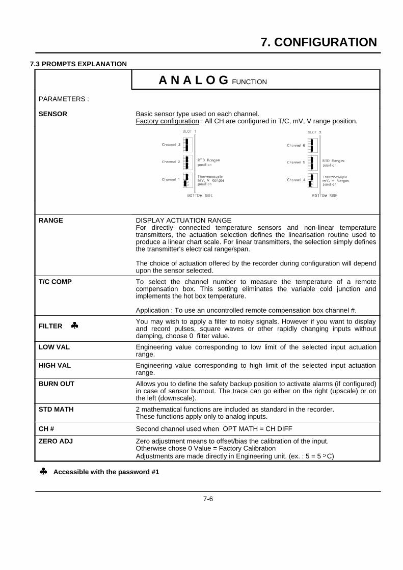
SENSOR Basic sensor type used on each channel.Factory configuration : All CH are configured in T/C, mV, V range position.
RANGE DISPLAY ACTUATION RANGEFor directly connected temperature sensors and non-linear temperaturetransmitters, the actuation selection defines the linearisation routine used toproduce a linear chart scale. For linear transmitters, the selection simply definesthe transmitter's electrical range/span.
The choice of actuation offered by the recorder during configuration will dependupon the sensor selected.
T/C COMP To select the channel number to measure the temperature of a remotecompensation box. This setting eliminates the variable cold junction andimplements the hot box temperature.
Application : To use an uncontrolled remote compensation box channel #.
FILTER [You may wish to apply a filter to noisy signals. However if you want to displayand record pulses, square waves or other rapidly changing inputs withoutdamping, choose 0 filter value.
LOW VAL Engineering value corresponding to low limit of the selected input actuationrange.
HIGH VAL Engineering value corresponding to high limit of the selected input actuationrange.
BURN OUT Allows you to define the safety backup position to activate alarms (if configured)in case of sensor burnout. The trace can go either on the right (upscale) or onthe left (downscale).
STD MATH 2 mathematical functions are included as standard in the recorder.These functions apply only to analog inputs.
CH # Second channel used when OPT MATH = CH DIFF
ZERO ADJ Zero adjustment means to offset/bias the calibration of the input.Otherwise chose 0 Value = Factory CalibrationAdjustments are made directly in Engineering unit. (ex. : 5 = 5 oC)
[ Accessible with the password #1
7-6
7. CONFIGURATION
A L A R M A N FUNCTION
PARAMETERS :
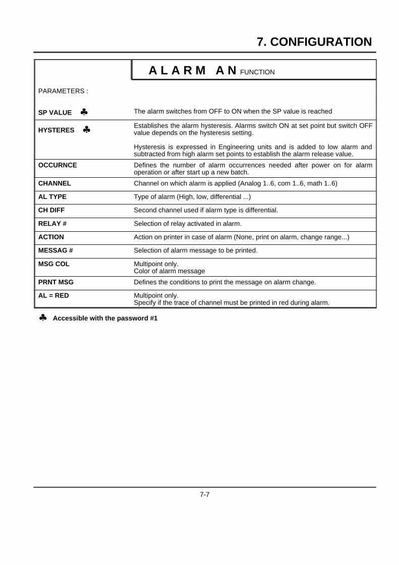
SP VALUE [ The alarm switches from OFF to ON when the SP value is reached
HYSTERES [Establishes the alarm hysteresis. Alarms switch ON at set point but switch OFFvalue depends on the hysteresis setting.
Hysteresis is expressed in Engineering units and is added to low alarm andsubtracted from high alarm set points to establish the alarm release value.
OCCURNCE Defines the number of alarm occurrences needed after power on for alarmoperation or after start up a new batch.
CHANNEL Channel on which alarm is applied (Analog 1..6, com 1..6, math 1..6)
AL TYPE Type of alarm (High, low, differential ...)
CH DIFF Second channel used if alarm type is differential.
RELAY # Selection of relay activated in alarm.
ACTION Action on printer in case of alarm (None, print on alarm, change range...)
MESSAG # Selection of alarm message to be printed.
MSG COL Multipoint only.Color of alarm message
PRNT MSG Defines the conditions to print the message on alarm change.
AL = RED Multipoint only.Specify if the trace of channel must be printed in red during alarm.
[ Accessible with the password #1
7-7

7. CONFIGURATION
D I G I T A L FUNCTION
PARAMETERS :
TYPE Type of digital input.
CH DIFF Second digital input to use if the type is differential.
ACTION Action on printer in case of digital input change.
RELAY # Selection of relay activated.
MESSAG # Selection of message to be printed.
MSG COL Multipoint only.Color of the message.
PRNT MSG Defines the condition to print the message on Event Change.
TRACE Enable/disable the trace of the event.
TR COLOR Multipoint only.Defines color of trace.
RED TRAC Multipoint only.Specify if digital input trace must be printed in red on event.
POSITION Multipoint only.Defines the trace position (open contact) on the chart. (in %)
M E S S A G E S FUNCTION
PARAMETERS :
MESSAGE [ To configure the messages (14 characters)
[ Accessible with the password #1
7-8
7. CONFIGURATION
C H A R T FUNCTION
PARAMETERS :
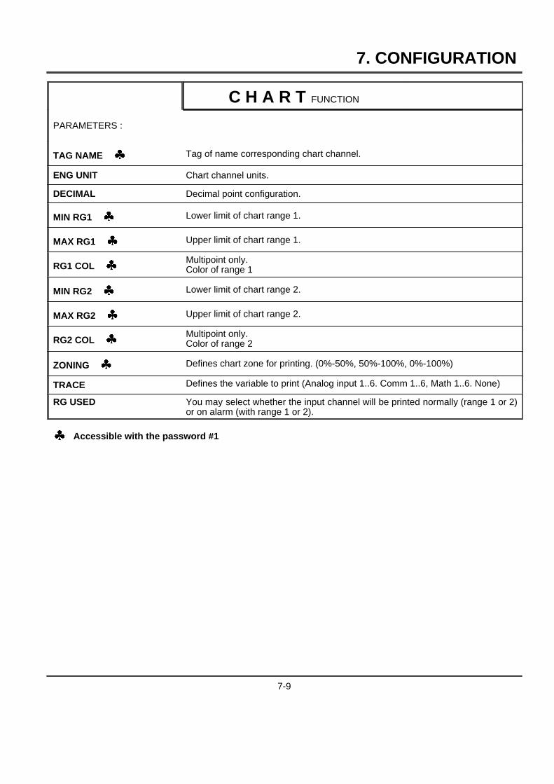
TAG NAME [ Tag of name corresponding chart channel.
ENG UNIT Chart channel units.
DECIMAL Decimal point configuration.
MIN RG1 [ Lower limit of chart range 1.
MAX RG1 [ Upper limit of chart range 1.
RG1 COL [Multipoint only.Color of range 1
MIN RG2 [ Lower limit of chart range 2.
MAX RG2 [ Upper limit of chart range 2.
RG2 COL [Multipoint only.Color of range 2
ZONING [ Defines chart zone for printing. (0%-50%, 50%-100%, 0%-100%)
TRACE Defines the variable to print (Analog input 1..6. Comm 1..6, Math 1..6. None)
RG USED You may select whether the input channel will be printed normally (range 1 or 2)or on alarm (with range 1 or 2).
[ Accessible with the password #1
7-9
7. CONFIGURATION
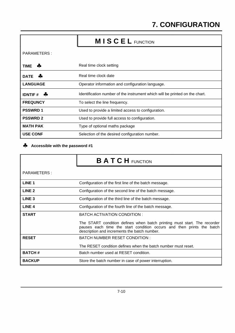
M I S C E L FUNCTION
PARAMETERS :
TIME [ Real time clock setting
DATE [ Real time clock date
LANGUAGE Operator information and configuration language.
IDNTIF # [ Identification number of the instrument which will be printed on the chart.
FREQUNCY To select the line frequency.
PSSWRD 1 Used to provide a limited access to configuration.
PSSWRD 2 Used to provide full access to configuration.
MATH PAK Type of optional maths package
USE CONF Selection of the desired configuration number.
[ Accessible with the password #1
B A T C H FUNCTION
PARAMETERS :
LINE 1 Configuration of the first line of the batch message.
LINE 2 Configuration of the second line of the batch message.
LINE 3 Configuration of the third line of the batch message.
LINE 4 Configuration of the fourth line of the batch message.
START BATCH ACTIVATION CONDITION :
The START condition defines when batch printing must start. The recorderpauses each time the start condition occurs and then prints the batchdescription and increments the batch number.
RESET BATCH NUMBER RESET CONDITION :
The RESET condition defines when the batch number must reset.
BATCH # Batch number used at RESET condition.
BACKUP Store the batch number in case of power interruption.
7-10

7. CONFIGURATION
P R I N T E R FUNCTION
PARAMETERS :
CHART LG Total chart length of the chart roll or fanfold
SPD UNIT [ Speed unit. (mm/h or inch/h)
SPEED1 [ Value of speed 1. (Using speed unit)
SPEED2 [ Value of speed 2.
SPD USED [ Defines the speed in use or the tabular in use.
TABULAR 1 [Multipoint only.Tab 1 prints interval. (In minute)
TABULAR 2 [Multipoint only.Tab 2 prints interval.
REC MODE Recording mode allows you to print normally, to stop the printer, to trigger theprinter on alarm with (or without) return to stand-by.
PRT MODE Multipoint only.Under this heading you must choose whether recording will be in trend mode ortabular mode.
PRT INTV Separation (in millimeters) of PRT PV interval for periodic printing.
PRINT PV Periodic printing of PV values, time and digital input status.
PRT RANG Periodic printing of the chart ranges.
PRT TIME Periodic printing of "TIME, DATE, SPEED, CHANNEL ID"
PRT TAG Multipoint only.Printing of the tag name with the channel number.
PEN OFFS Pen only.Pen offset.
[ Accessible with the password #1
E V E N T FUNCTION
PARAMETERS :
TYPE Type of event.
RELAY # Selection of relay activated in event condition.
DISPLAY Enable/disable a display warning in event occurrence.
7-11
7. CONFIGURATION
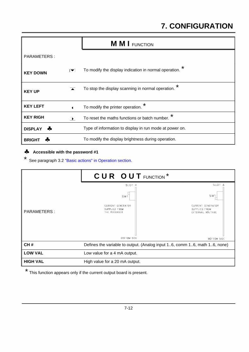
M M I FUNCTION
PARAMETERS :
KEY DOWN ] To modify the display indication in normal operation. *
KEY UP [ To stop the display scanning in normal operation. *
KEY LEFT { To modify the printer operation. *KEY RIGH } To reset the maths functions or batch number. *
DISPLAY [ Type of information to display in run mode at power on.
BRIGHT [ To modify the display brightness during operation.
[ Accessible with the password #1
* See paragraph 3.2 "Basic actions" in Operation section.
C U R O U T FUNCTION *
PARAMETERS :
CH # Defines the variable to output. (Analog input 1..6, comm 1..6, math 1..6, none)
LOW VAL Low value for a 4 mA output.
HIGH VAL High value for a 20 mA output.
* This function appears only if the current output board is present.
7-12

8. DETAILED CONFIGURATION
8.1 PARAMETERS LIST
FUNCTION PARAMETER CLASSIFICATION
NAME OF THEFUNCTION
NAME OF THEPARAMETER
IMPORTANCE OF THEPARAMETER :
}RARELY USED
}}NOT OFTEN USED
}}}OFTEN USED
DEFINITION : EXPLAIN THE ROLE OF THE PARAMETER
HOW TO MODIFY IT : 2 POSSIBILITIES :
- BY SELECTING A NEW VALUE I.E. USING THE][ KEYS
- BY ENTERING A NEW VALUE
POSSIBLE VALUES : LIST OF POSSIBLE VALUES OR LIMITS
SEE ALSO :
EXAMPLE :
NOTE :
WARNING :
8-1
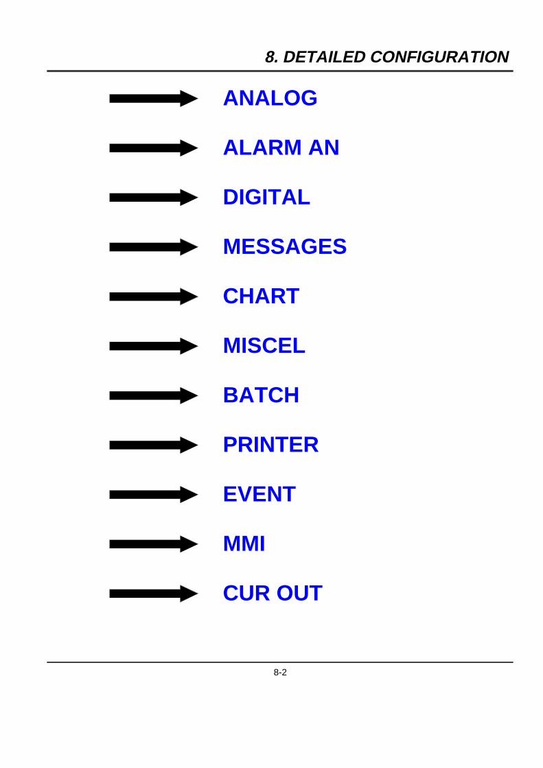
8. DETAILED CONFIGURATION
ANALOG
ALARM AN
DIGITAL
MESSAGES
CHART
MISCEL
BATCH
PRINTER
EVENT
MMI
CUR OUT
8-2
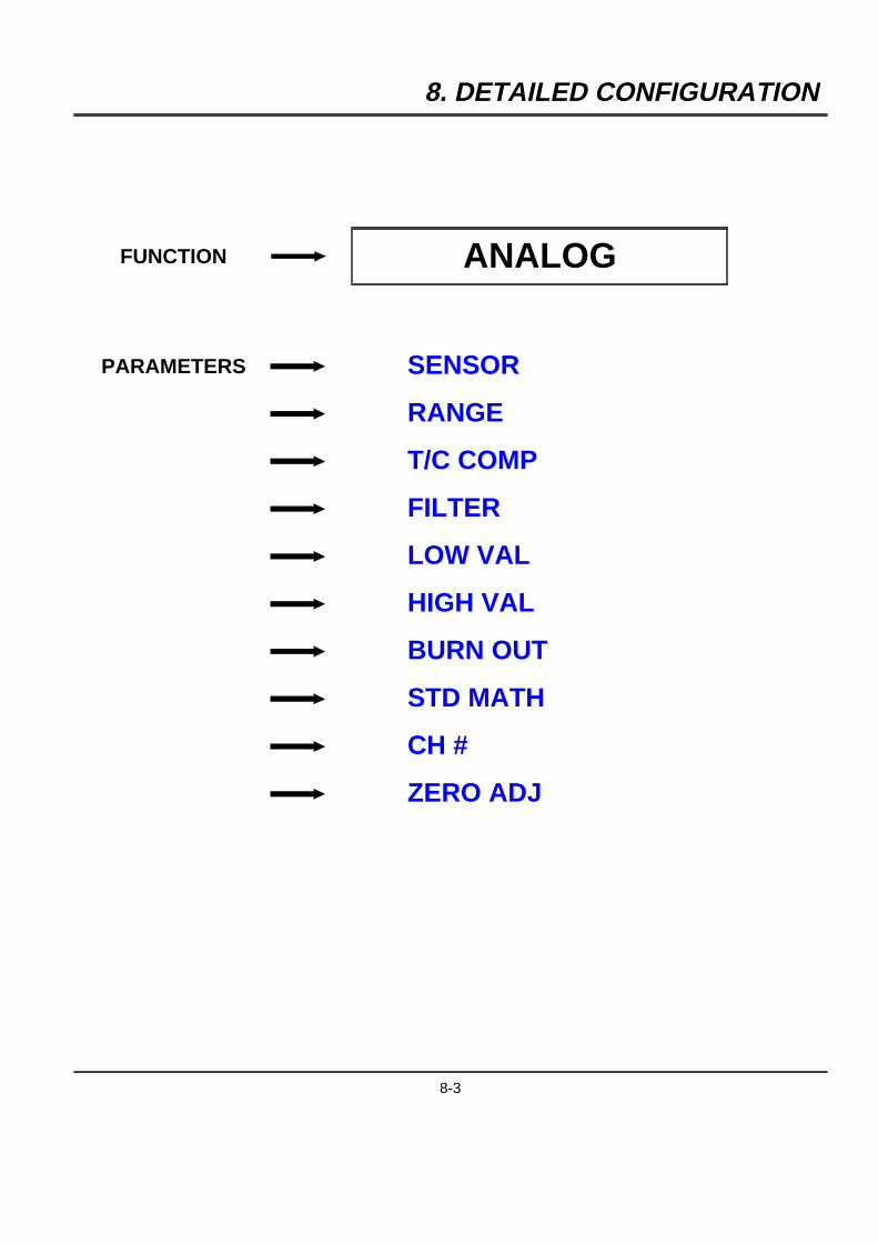
8. DETAILED CONFIGURATION
FUNCTION ANALOG
PARAMETERS SENSOR
RANGE
T/C COMP
FILTER
LOW VAL
HIGH VAL
BURN OUT
STD MATH
CH #
ZERO ADJ
8-3
8. DETAILED CONFIGURATION
FUNCTION PARAMETER CLASSIFICATION
ANALOG S E N S O R }}}
DEFINITION : Basic sensor type used on each channel.
HOW TO MODIFY IT : Select a new sensor.
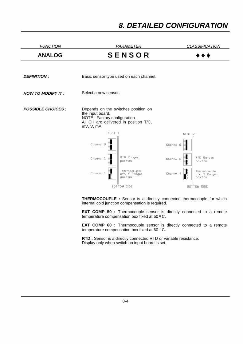
POSSIBLE CHOICES : Depends on the switches position onthe input board.NOTE : Factory configuration.All CH are delivered in position T/C,mV, V, mA
THERMOCOUPLE : Sensor is a directly connected thermocouple for whichinternal cold junction compensation is required.
EXT COMP 50 : Thermocouple sensor is directly connected to a remotetemperature compensation box fixed at 50 oC.
EXT COMP 60 : Thermocouple sensor is directly connected to a remotetemperature compensation box fixed at 60 oC.
RTD : Sensor is a directly connected RTD or variable resistance.Display only when switch on input board is set.
8-4
8. DETAILED CONFIGURATION
FUNCTION PARAMETER CLASSIFICATION
ANALOG S E N S O R }}}
TR NL 0-5V : Sensor is a temperature transmitter; signal range of 0-5V is notlinear with temperature.
TR NL 1-5V : Sensor is a temperature transmitter; signal range of 1-5V is notlinear with temperature.
TR NL 0-20mA : Sensor is a temperature transmitter; signal range of 0-20mA isnot linear with temperature.
TR NL 4-20mA : Sensor is a temperature transmitter; signal range of 4-20mA isnot linear with temperature.
LINEAR : Sensor is a transmitter; output is linear with process variable.
SPECIAL : Special sensor connected. Must be specified by special order.
NO ENTRY : No sensor connected or unused input.
SEE ALSO : RANGE in this function.
NOTE : Changing the sensor type will automatically change RANGE, LOW VAL, HIGHVAL into predefined values.
8-5
8. DETAILED CONFIGURATION
FUNCTION PARAMETER CLASSIFICATION
ANALOG R A N G E }}}
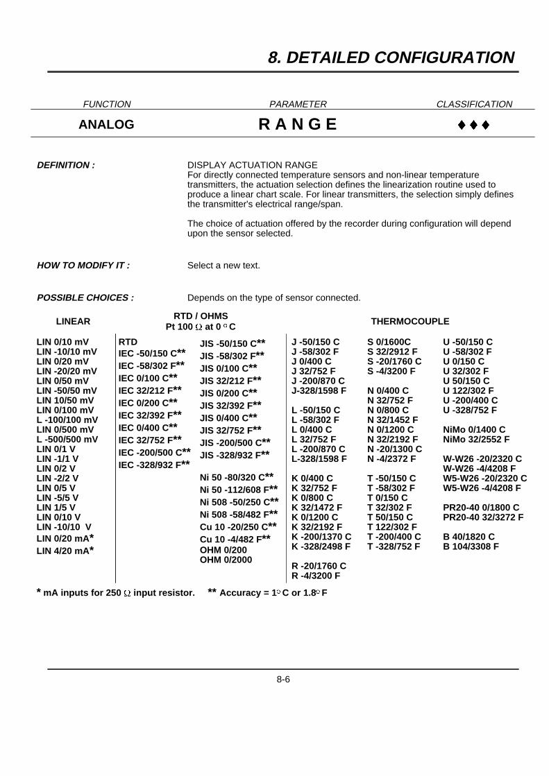
DEFINITION : DISPLAY ACTUATION RANGEFor directly connected temperature sensors and non-linear temperaturetransmitters, the actuation selection defines the linearization routine used toproduce a linear chart scale. For linear transmitters, the selection simply definesthe transmitter's electrical range/span.
The choice of actuation offered by the recorder during configuration will dependupon the sensor selected.
HOW TO MODIFY IT : Select a new text.
POSSIBLE CHOICES : Depends on the type of sensor connected.
LINEAR RTD / OHMSPt 100 W at 0 oC THERMOCOUPLE
LIN 0/10 mVLIN -10/10 mVLIN 0/20 mVLIN -20/20 mVLIN 0/50 mVLIN -50/50 mVLIN 10/50 mVLIN 0/100 mVL -100/100 mVLIN 0/500 mVL -500/500 mVLIN 0/1 VLIN -1/1 VLIN 0/2 VLIN -2/2 VLIN 0/5 VLIN -5/5 VLIN 1/5 VLIN 0/10 VLIN -10/10 VLIN 0/20 mA*LIN 4/20 mA*
RTDIEC -50/150 C**IEC -58/302 F**IEC 0/100 C**IEC 32/212 F**IEC 0/200 C**IEC 32/392 F**IEC 0/400 C**IEC 32/752 F**IEC -200/500 C**IEC -328/932 F**
JIS -50/150 C**JIS -58/302 F**JIS 0/100 C**JIS 32/212 F**JIS 0/200 C**JIS 32/392 F**JIS 0/400 C**JIS 32/752 F**JIS -200/500 C**JIS -328/932 F**
Ni 50 -80/320 C**Ni 50 -112/608 F**Ni 508 -50/250 C**Ni 508 -58/482 F**Cu 10 -20/250 C**Cu 10 -4/482 F**OHM 0/200OHM 0/2000
J -50/150 CJ -58/302 FJ 0/400 CJ 32/752 FJ -200/870 CJ-328/1598 F
L -50/150 CL -58/302 FL 0/400 CL 32/752 FL -200/870 CL-328/1598 F
K 0/400 CK 32/752 FK 0/800 CK 32/1472 FK 0/1200 CK 32/2192 FK -200/1370 CK -328/2498 F
R -20/1760 CR -4/3200 F
S 0/1600CS 32/2912 FS -20/1760 CS -4/3200 F
N 0/400 CN 32/752 FN 0/800 CN 32/1452 FN 0/1200 CN 32/2192 FN -20/1300 CN -4/2372 F
T -50/150 CT -58/302 FT 0/150 CT 32/302 FT 50/150 CT 122/302 FT -200/400 CT -328/752 F
U -50/150 CU -58/302 FU 0/150 CU 32/302 FU 50/150 CU 122/302 FU -200/400 CU -328/752 F
NiMo 0/1400 CNiMo 32/2552 F
W-W26 -20/2320 CW-W26 -4/4208 FW5-W26 -20/2320 CW5-W26 -4/4208 F
PR20-40 0/1800 CPR20-40 32/3272 F
B 40/1820 CB 104/3308 F
* mA inputs for 250 W input resistor. ** Accuracy = 1oC or 1.8oF
8-6

8. DETAILED CONFIGURATION
FUNCTION PARAMETER CLASSIFICATION
ANALOG R A N G E }}}
NOTE : For non-linear temperature transmitter 1 to 5 VDC or 4 to 20 mA or 0 to 5 VDC or 0to 20 mA. The transmitter range must be identical to the actuation/displays shownabove.
Provision for T/C input, for remote compensation box :- at fixed temperature 50 oC or 60 oC.- or at not fixed temperature, one input used as remote compensation temperaturemeasurement.
WARNING : F is used for oFahrenheit; C is used for oCelcius.
8-7
8. DETAILED CONFIGURATION
FUNCTION PARAMETER CLASSIFICATION
ANALOG T / C COMP }
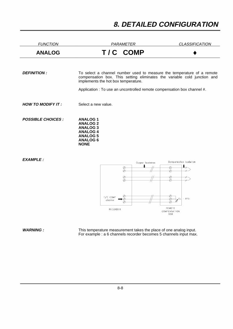
DEFINITION : To select a channel number used to measure the temperature of a remotecompensation box. This setting eliminates the variable cold junction andimplements the hot box temperature.
Application : To use an uncontrolled remote compensation box channel #.
HOW TO MODIFY IT : Select a new value.
POSSIBLE CHOICES : ANALOG 1ANALOG 2ANALOG 3ANALOG 4ANALOG 5ANALOG 6NONE
EXAMPLE :
WARNING : This temperature measurement takes the place of one analog input.For example : a 6 channels recorder becomes 5 channels input max.
8-8
8. DETAILED CONFIGURATION
FUNCTION PARAMETER CLASSIFICATION
ANALOG F I L T E R }
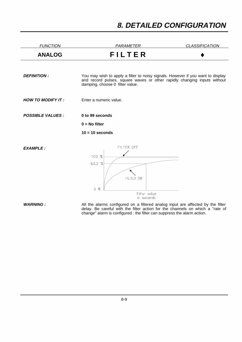
DEFINITION : You may wish to apply a filter to noisy signals. However if you want to displayand record pulses, square waves or other rapidly changing inputs withoutdamping, choose 0 filter value.
HOW TO MODIFY IT : Enter a numeric value.
POSSIBLE VALUES : 0 to 99 seconds
0 = No filter
10 = 10 seconds
EXAMPLE :
WARNING : All the alarms configured on a filtered analog input are affected by the filterdelay. Be careful with the filter action for the channels on which a "rate ofchange" alarm is configured : the filter can suppress the alarm action.
8-9
8. DETAILED CONFIGURATION
FUNCTION PARAMETER CLASSIFICATION
ANALOG L O W V A L }}
DEFINITION : Engineering value corresponding to low limit of the selected input actuationrange.
HOW TO MODIFY IT : Enter a numeric value.
POSSIBLE VALUES : Up to 6 digits including negative sign and decimal point.[-9999 ... 9999]
WARNING : Modification is not available for any directly connected temperature sensors, asthis would adversely affect the linearization.
For linear and non-linear transmitters choose the value in engineering units,which corresponds to the low range limit of the transmitter.
FUNCTION PARAMETER CLASSIFICATION
ANALOG H I G H V A L }}
DEFINITION : Engineering value corresponding to high limit of the selected input actuationrange.
HOW TO MODIFY IT : Enter a numeric value.
POSSIBLE VALUES : Up to 6 digits including negative sign and decimal point.[-9999 ... 9999]
WARNING : Modification is not available for any directly connected temperature sensors, asthis would adversely affect the linearization.
For linear and non-linear transmitters choose the value in engineering units,which corresponds to the high range limit of the transmitter.
8-10
8. DETAILED CONFIGURATION
FUNCTION PARAMETER CLASSIFICATION
ANALOG B U R N O U T }
DEFINITION : Allows you to define the safety backup position to activate alarms (if configured)in case of sensor burnout. The trace can go either on the right (upscale) or onthe left (downscale).
HOW TO MODIFY IT : Select new text.
POSSIBLE CHOICES : NO B.OUT : No burn out.
B.OUT LOW : Burn out configureddownscale.
B.OUT HIGH : Burn out configuredupscale.
FIX LOW : Burn out fixed low.
FIX HIGH : Burn out fixed high.(RTD/OHMS)
FIX NONE : Burn out fixed none.(Linear sensors)-10 10 V / 0 10 V / -5 5 V / -2 2 V /-1 1 V / -500 500 mV
Not configurable
NOTE : For some sensors, burn out is not configurable but fixed and display will showFIX LOW, FIX HIGH (RTD/OHMS) or FIX NONE.
WARNING For configurable burnout, be aware that a current of 0.125 mA will occurregularly and may disturb other devices connected to the same sensor.
8-11

8. DETAILED CONFIGURATION
FUNCTION PARAMETER CLASSIFICATION
ANALOG S T D M A T H }
DEFINITION : 2 mathematical functions are included as standard in the recorder.These functions apply only to analog inputs.
HOW TO MODIFY IT : Select new math function.
POSSIBLE CHOICES : NO OPT MATH : No math function configured.
SQUARE ROOT : Square root applies to analog input.
CHANNEL DIFF : Difference between the current analog input and the oneconfigured in "CH#".
SEE ALSO : -CH# in this sub-matrix for CHANNEL DIFF.
NOTE : The function result is displayed and printed on the concerned analog channel.
- For the square root (SQUARE),the formula is :
PV =(S - Smin) (HIGH VAL2 - LOW VAL2)
+ LOW VAL2(Smax - Smin)
Smin = min. sensor input valueSmax = max. sensor input valueS = current sensor input valueHIGH = high scale valueLOW = low scale value
- For CHANNEL DIFF, the formula is :PV = PV
A- PV
BA and B are any analog input.
8-12
8. DETAILED CONFIGURATION
FUNCTION PARAMETER CLASSIFICATION
ANALOG C H # }
DEFINITION : Second channel used when OPT MATH = CH DIFF
HOW TO MODIFY IT : Select a new value.
POSSIBLE CHOICES : ANALOG 1ANALOG 2ANALOG 3ANALOG 4ANALOG 5ANALOG 6NONE
NOTE : Analog input must be already configured to be accepted by the software.
8-13
8. DETAILED CONFIGURATION
FUNCTION PARAMETER CLASSIFICATION
ANALOG Z E R O A D J }
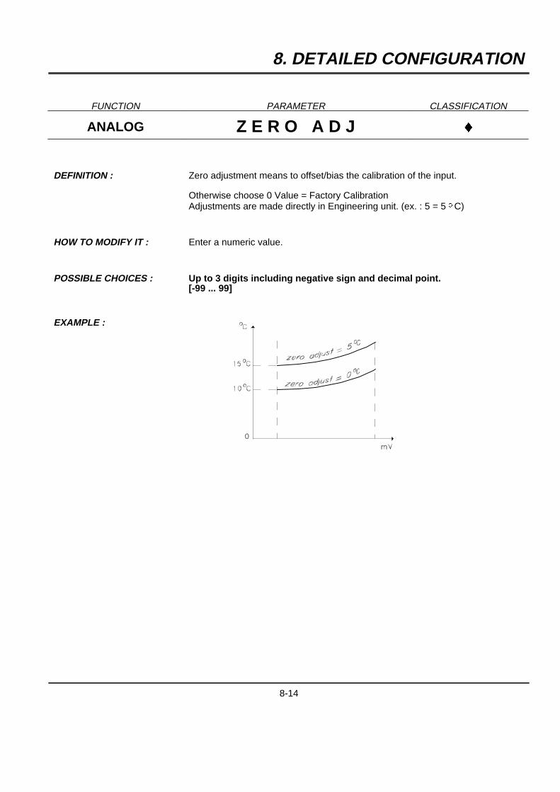
DEFINITION : Zero adjustment means to offset/bias the calibration of the input.
Otherwise choose 0 Value = Factory CalibrationAdjustments are made directly in Engineering unit. (ex. : 5 = 5 oC)
HOW TO MODIFY IT : Enter a numeric value.
POSSIBLE CHOICES : Up to 3 digits including negative sign and decimal point.[-99 ... 99]
EXAMPLE :
8-14
8. DETAILED CONFIGURATION
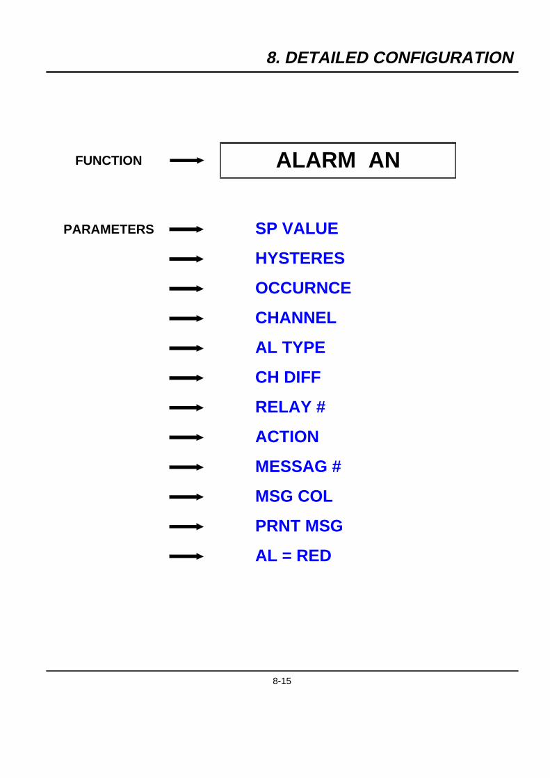
FUNCTION ALARM AN
PARAMETERS SP VALUE
HYSTERES
OCCURNCE
CHANNEL
AL TYPE
CH DIFF
RELAY #
ACTION
MESSAG #
MSG COL
PRNT MSG
AL = RED
8-15
8. DETAILED CONFIGURATION
FUNCTION PARAMETER CLASSIFICATION
ALARM AN S P V A L U E }}}
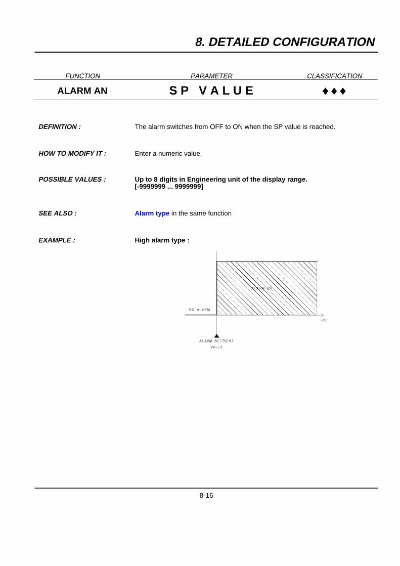
DEFINITION : The alarm switches from OFF to ON when the SP value is reached.
HOW TO MODIFY IT : Enter a numeric value.
POSSIBLE VALUES : Up to 8 digits in Engineering unit of the display range.[-9999999 ... 9999999]
SEE ALSO : Alarm type in the same function
EXAMPLE : High alarm type :
�����������
�����������
�����������
�����������
�����������
�����������
�����������
�����������
�����������
�����������
�����������
�����������
�����������
�����������
�����������
�����������
�����������
�����������
�����������
�����������
8-16
8. DETAILED CONFIGURATION
FUNCTION PARAMETER CLASSIFICATION
ALARM AN H Y S T E R E S }}
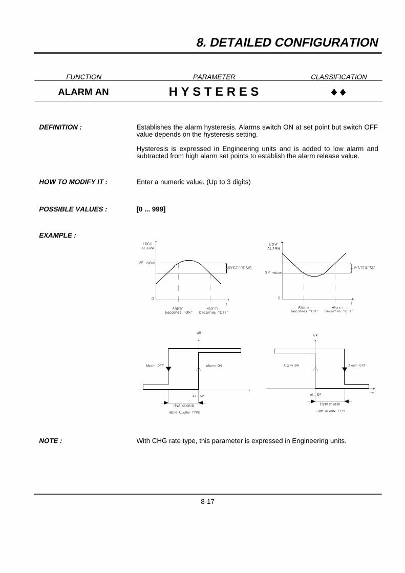
DEFINITION : Establishes the alarm hysteresis. Alarms switch ON at set point but switch OFFvalue depends on the hysteresis setting.
Hysteresis is expressed in Engineering units and is added to low alarm andsubtracted from high alarm set points to establish the alarm release value.
HOW TO MODIFY IT : Enter a numeric value. (Up to 3 digits)
POSSIBLE VALUES : [0 ... 999]
EXAMPLE :
NOTE : With CHG rate type, this parameter is expressed in Engineering units.
8-17
8. DETAILED CONFIGURATION
FUNCTION PARAMETER CLASSIFICATION
ALARM AN O C C U R N C E }
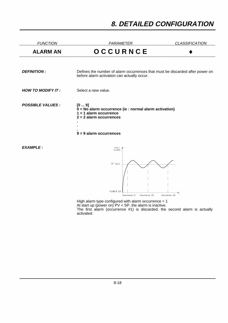
DEFINITION : Defines the number of alarm occurrences that must be discarded after power onbefore alarm activation can actually occur.
HOW TO MODIFY IT : Select a new value.
POSSIBLE VALUES : [0 ... 9]0 = No alarm occurrence (ie : normal alarm activation)1 = 1 alarm occurrence2 = 2 alarm occurrences...9 = 9 alarm occurrences
EXAMPLE :
High alarm type configured with alarm occurrence = 1At start up (power on) PV < SP, the alarm is inactive.The first alarm (occurrence #1) is discarded, the second alarm is actuallyactivated.
8-18
8. DETAILED CONFIGURATION
FUNCTION PARAMETER CLASSIFICATION
ALARM AN C H A N N E L }}}
DEFINITION : Channel on which alarm is applied. (Analog 1..6, com 1..6, math 1..6)
HOW TO MODIFY IT : Select a new value.
POSSIBLE CHOICES : ANALOG 1ANALOG 2ANALOG 3ANALOG 4ANALOG 5ANALOG 6
COMM 1COMM 2COMM 3COMM 4COMM 5COMM 6
MATH 1MATH 2MATH 3MATH 4MATH 5MATH 6
8-19
8. DETAILED CONFIGURATION
FUNCTION PARAMETER CLASSIFICATION
ALARM AN A L T Y P E }}}
DEFINITION : Type of alarm (High, low, differential ...)
HOW TO MODIFY IT : Select a new alarm type.
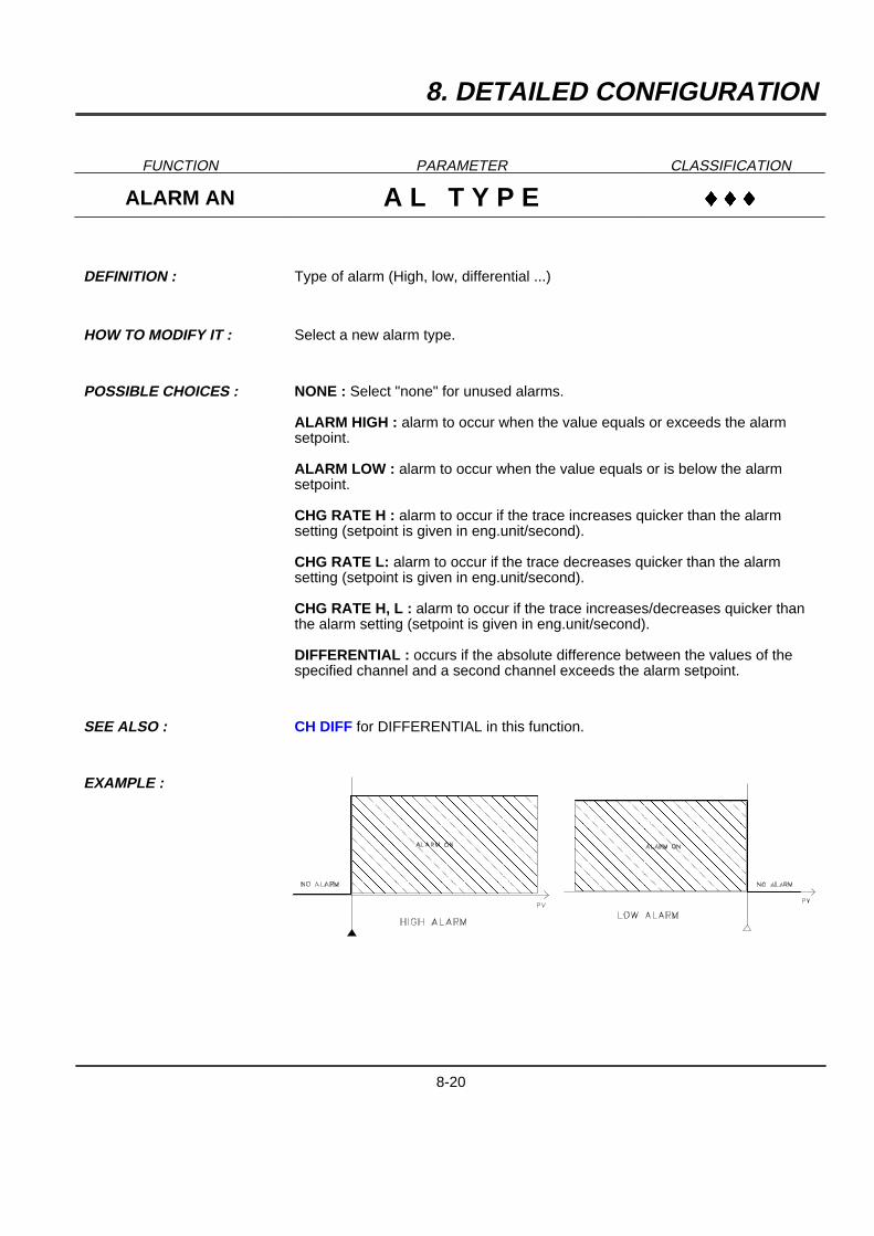
POSSIBLE CHOICES : NONE : Select "none" for unused alarms.
ALARM HIGH : alarm to occur when the value equals or exceeds the alarmsetpoint.
ALARM LOW : alarm to occur when the value equals or is below the alarmsetpoint.
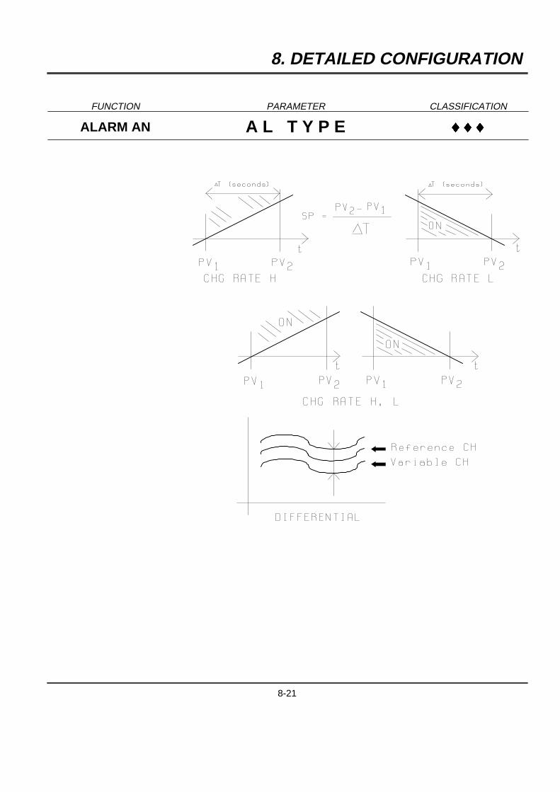
CHG RATE H : alarm to occur if the trace increases quicker than the alarmsetting (setpoint is given in eng.unit/second).
CHG RATE L: alarm to occur if the trace decreases quicker than the alarmsetting (setpoint is given in eng.unit/second).
CHG RATE H, L : alarm to occur if the trace increases/decreases quicker thanthe alarm setting (setpoint is given in eng.unit/second).
DIFFERENTIAL : occurs if the absolute difference between the values of thespecified channel and a second channel exceeds the alarm setpoint.
SEE ALSO : CH DIFF for DIFFERENTIAL in this function.
EXAMPLE :
���������
���������
���������
���������
���������
���������
���������
���������
���������
���������
���������
���������
���������
���������
���������
���������
���������
��������
��������
��������
��������
��������
��������
��������
��������
��������
��������
��������
��������
��������
��������
��������
��������
8-20
8. DETAILED CONFIGURATION
FUNCTION PARAMETER CLASSIFICATION
ALARM AN A L T Y P E }}}
8-21
8. DETAILED CONFIGURATION
FUNCTION PARAMETER CLASSIFICATION
ALARM AN A L T Y P E }}}
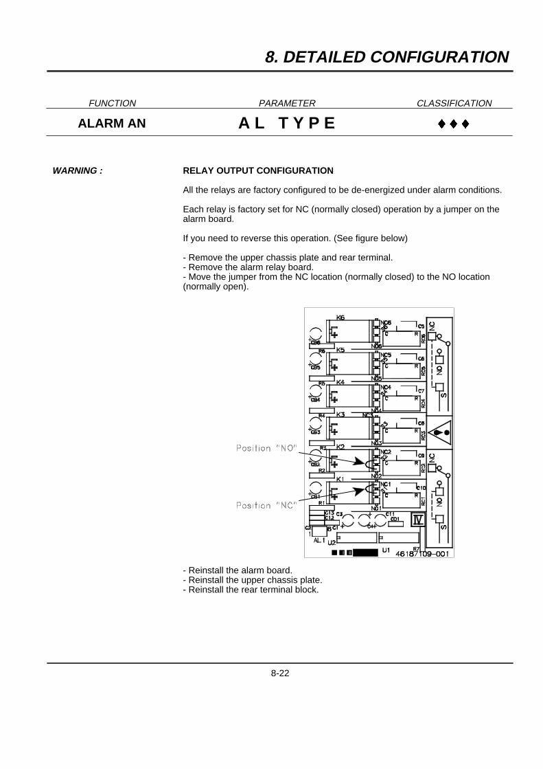
WARNING : RELAY OUTPUT CONFIGURATION
All the relays are factory configured to be de-energized under alarm conditions.
Each relay is factory set for NC (normally closed) operation by a jumper on thealarm board.
If you need to reverse this operation. (See figure below)
- Remove the upper chassis plate and rear terminal.- Remove the alarm relay board.- Move the jumper from the NC location (normally closed) to the NO location(normally open).
- Reinstall the alarm board.- Reinstall the upper chassis plate.- Reinstall the rear terminal block.
8-22
8. DETAILED CONFIGURATION
FUNCTION PARAMETER CLASSIFICATION
ALARM AN C H D I F F }
DEFINITION : Second channel to use if alarm type is differential.
HOW TO MODIFY IT : Select a new value.
POSSIBLE CHOICES : The same as those for alarm channel.
ANALOG 1ANALOG 2ANALOG 3ANALOG 4ANALOG 5ANALOG 6
COMM 1COMM 2COMM 3COMM 4COMM 5COMM 6
MATH 1MATH 2MATH 3MATH 4MATH 5MATH 6
8-23
8. DETAILED CONFIGURATION
FUNCTION PARAMETER CLASSIFICATION
ALARM AN R E L A Y # }}}
DEFINITION : Selection of relay to activate in alarm.
HOW TO MODIFY IT : Select a new relay number.
POSSIBLE CHOICES : NO RELAYRELAY 1RELAY 2RELAY 3RELAY 4RELAY 5RELAY 6RELAY 7RELAY 8RELAY 9RELAY 10RELAY 11RELAY 12
8-24
8. DETAILED CONFIGURATION
FUNCTION PARAMETER CLASSIFICATION
ALARM AN A C T I O N }}}
DEFINITION : Action on printer or on math functions in case of alarm (None, print on al.,change range...)
HOW TO MODIFY IT : Select a new alarm action.
POSSIBLE CHOICES :
*
*
*
**
************
NO ACTION : No effect on printing
CHG SPD/TAB2 : Change to chart speed/print interval 2 if SPD USED =SPD/TAB1 and to speed/print interval 1 if SPD USED = SPD/TAB2.
CHG RANGE 2 : Change to range 2 if RG USED = with R1 and to range 1 ifRG USED = with R2
PRINT ON AL : Print the channel in alarm condition.
PRN INHIBIT : Stop all printing
PV TAB TRACE : Print one tabular snapshot of values superposed ontraces.
PV TAB BLANK : Print one tabular snapshot of values on blank paper.
TRIG EV PREC : Triggers "event precursor" printing
PRT MATH LOG : Print one tabular snapshot of math results
HOLD MATH1 : Hold Math1 calculationHOLD MATH2 : Hold Math2 calculationHOLD MATH3 : Hold Math3 calculationHOLD MATH4 : Hold Math4 calculationHOLD MATH5 : Hold Math5 calculationHOLD MATH6 : Hold Math6 calculation
SEE ALSO : RG USED in CHART FUNCTION for PRINT ON AL
REC MODE in PRINTER FUNCTION for TRIG EV PREC
NOTE : ***
Available only on Multipoint recorders.Available only if the Math functions are released.
WARNING : When the alarm state switches from ON to OFF or conversely and whenrecorder is configured with PRN INHIBIT : the messages, the PV printout andthe batch messages are not printed.
8-25
8. DETAILED CONFIGURATION
FUNCTION PARAMETER CLASSIFICATION
ALARM AN M E S S A G # }}}
DEFINITION : Selection of alarm message to be printed.
HOW TO MODIFY IT : Select a new message number.
POSSIBLE CHOICES : MESSAGE #1MESSAGE #2MESSAGE #3MESSAGE #4MESSAGE #5MESSAGE #6MESSAGE #7MESSAGE #8MESSAGE #9MESSAGE #10MESSAGE #11MESSAGE #12
SEE ALSO : PRNT MSG in this function
WARNING : Be sure the selected message is already configured. (See Matrix Message)
8-26
8. DETAILED CONFIGURATION
FUNCTION PARAMETER CLASSIFICATION
ALARM AN M S G C O L }}
DEFINITION : Color of alarm message
HOW TO MODIFY IT : Select a new color.
POSSIBLE CHOICES : PURPLE
RED
BLACK
GREEN
BLUE
BROWN
WARNING THIS FUNCTION IS ONLY AVAILABLE FOR MULTIPOINT RECORDERS.
8-27
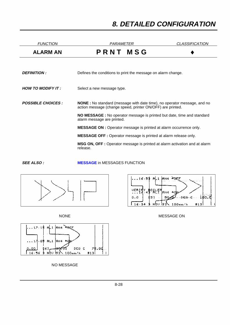
8. DETAILED CONFIGURATION
FUNCTION PARAMETER CLASSIFICATION
ALARM AN P R N T M S G }
DEFINITION : Defines the conditions to print the message on alarm change.
HOW TO MODIFY IT : Select a new message type.
POSSIBLE CHOICES : NONE : No standard (message with date time), no operator message, and noaction message (change speed, printer ON/OFF) are printed.
NO MESSAGE : No operator message is printed but date, time and standardalarm message are printed.
MESSAGE ON : Operator message is printed at alarm occurrence only.
MESSAGE OFF : Operator message is printed at alarm release only.
MSG ON, OFF : Operator message is printed at alarm activation and at alarmrelease.
SEE ALSO : MESSAGE in MESSAGES FUNCTION
NONE
NO MESSAGE
MESSAGE ON
8-28
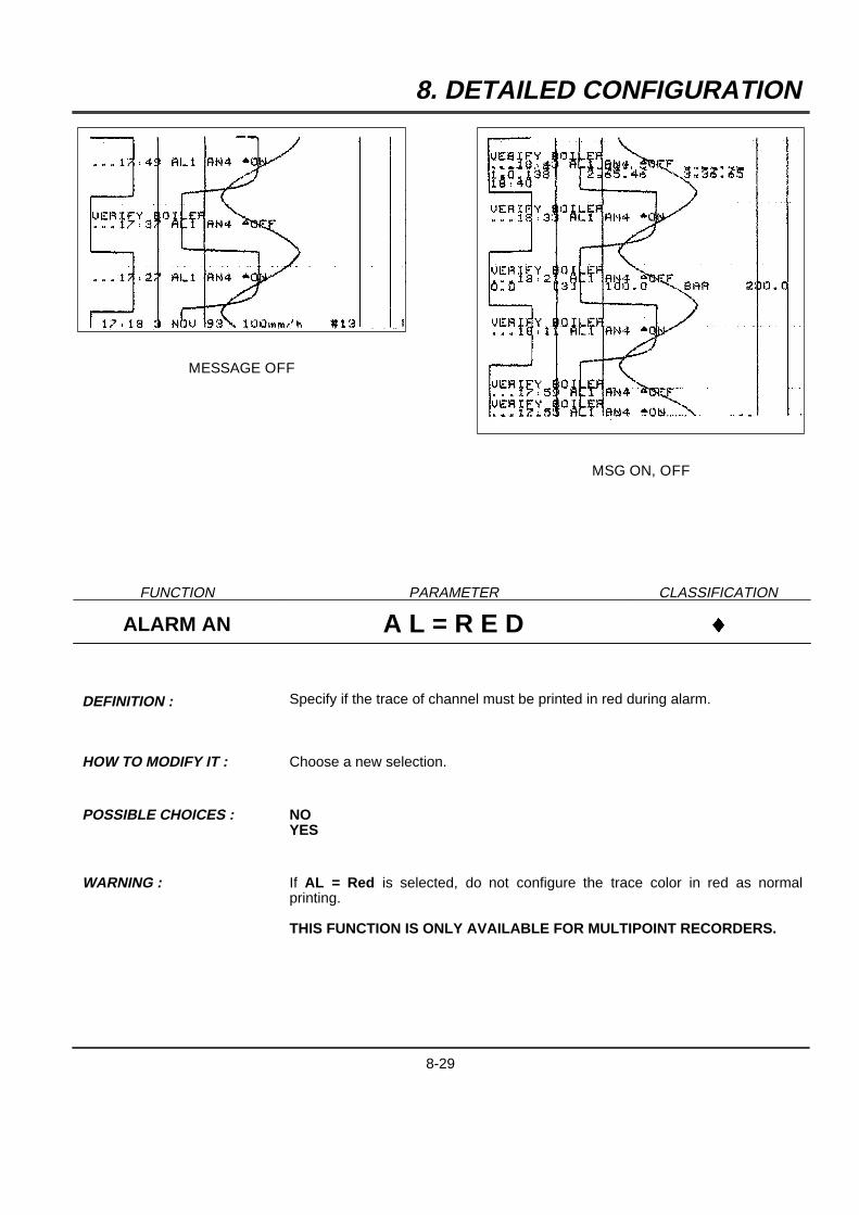
8. DETAILED CONFIGURATION
MESSAGE OFF
MSG ON, OFF
FUNCTION PARAMETER CLASSIFICATION
ALARM AN A L = R E D }
DEFINITION : Specify if the trace of channel must be printed in red during alarm.
HOW TO MODIFY IT : Choose a new selection.
POSSIBLE CHOICES : NOYES
WARNING : If AL = Red is selected, do not configure the trace color in red as normalprinting.
THIS FUNCTION IS ONLY AVAILABLE FOR MULTIPOINT RECORDERS.
8-29
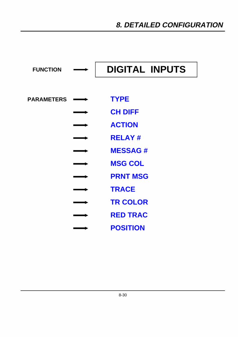
8. DETAILED CONFIGURATION
FUNCTION DIGITAL INPUTS
PARAMETERS TYPE
CH DIFF
ACTION
RELAY #
MESSAG #
MSG COL
PRNT MSG
TRACE
TR COLOR
RED TRAC
POSITION
8-30
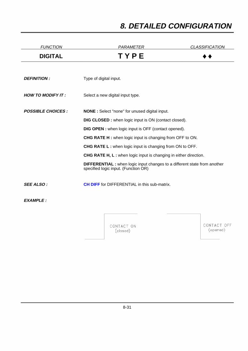
8. DETAILED CONFIGURATION
FUNCTION PARAMETER CLASSIFICATION
DIGITAL T Y P E }}
DEFINITION : Type of digital input.
HOW TO MODIFY IT : Select a new digital input type.
POSSIBLE CHOICES : NONE : Select "none" for unused digital input.
DIG CLOSED : when logic input is ON (contact closed).
DIG OPEN : when logic input is OFF (contact opened).
CHG RATE H : when logic input is changing from OFF to ON.
CHG RATE L : when logic input is changing from ON to OFF.
CHG RATE H, L : when logic input is changing in either direction.
DIFFERENTIAL : when logic input changes to a different state from anotherspecified logic input. (Function OR)
SEE ALSO : CH DIFF for DIFFERENTIAL in this sub-matrix.
EXAMPLE :
8-31
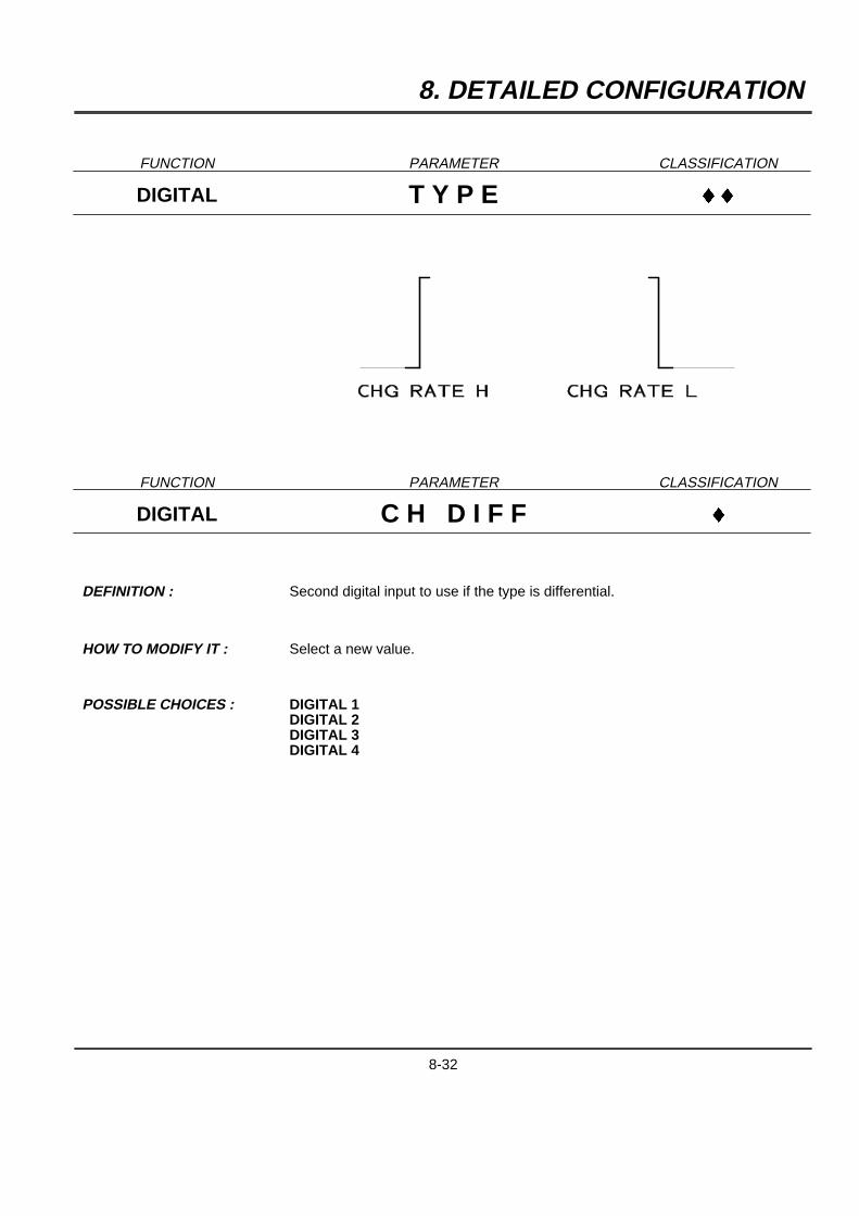
8. DETAILED CONFIGURATION
FUNCTION PARAMETER CLASSIFICATION
DIGITAL T Y P E }}
FUNCTION PARAMETER CLASSIFICATION
DIGITAL C H D I F F }
DEFINITION : Second digital input to use if the type is differential.
HOW TO MODIFY IT : Select a new value.
POSSIBLE CHOICES : DIGITAL 1DIGITAL 2DIGITAL 3DIGITAL 4
8-32
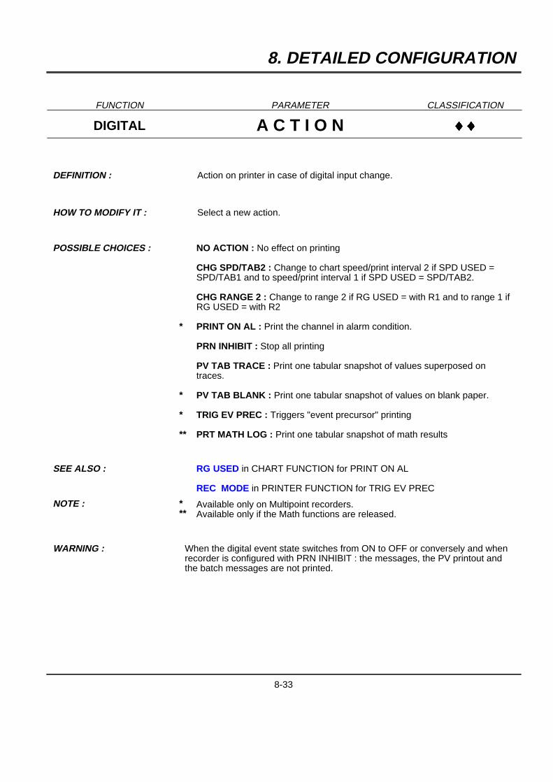
8. DETAILED CONFIGURATION
FUNCTION PARAMETER CLASSIFICATION
DIGITAL A C T I O N }}
DEFINITION : Action on printer in case of digital input change.
HOW TO MODIFY IT : Select a new action.
POSSIBLE CHOICES :
*
*
*
**
NO ACTION : No effect on printing
CHG SPD/TAB2 : Change to chart speed/print interval 2 if SPD USED =SPD/TAB1 and to speed/print interval 1 if SPD USED = SPD/TAB2.
CHG RANGE 2 : Change to range 2 if RG USED = with R1 and to range 1 ifRG USED = with R2
PRINT ON AL : Print the channel in alarm condition.
PRN INHIBIT : Stop all printing
PV TAB TRACE : Print one tabular snapshot of values superposed ontraces.
PV TAB BLANK : Print one tabular snapshot of values on blank paper.
TRIG EV PREC : Triggers "event precursor" printing
PRT MATH LOG : Print one tabular snapshot of math results
SEE ALSO : RG USED in CHART FUNCTION for PRINT ON AL
REC MODE in PRINTER FUNCTION for TRIG EV PREC
NOTE : ***
Available only on Multipoint recorders.Available only if the Math functions are released.
WARNING : When the digital event state switches from ON to OFF or conversely and whenrecorder is configured with PRN INHIBIT : the messages, the PV printout andthe batch messages are not printed.
8-33

8. DETAILED CONFIGURATION
FUNCTION PARAMETER CLASSIFICATION
DIGITAL R E L A Y # }}
DEFINITION : Selection of relay activated.
HOW TO MODIFY IT : Select a new relay number.
POSSIBLE CHOICES : NO RELAYRELAY 1RELAY 2RELAY 3RELAY 4RELAY 5RELAY 6RELAY 7RELAY 8RELAY 9RELAY 10RELAY 11RELAY 12
8-34
8. DETAILED CONFIGURATION
FUNCTION PARAMETER CLASSIFICATION
DIGITAL M E S S A G # }}
DEFINITION : Selection of message to be printed.
HOW TO MODIFY IT : Select a new message number.
POSSIBLE CHOICES : MESSAGE #1MESSAGE #2MESSAGE #3MESSAGE #4MESSAGE #5MESSAGE #6MESSAGE #7MESSAGE #8MESSAGE #9MESSAGE #10MESSAGE #11MESSAGE #12
SEE ALSO : PRNT MSG in this sub-matrix
8-35

8. DETAILED CONFIGURATION
FUNCTION PARAMETER CLASSIFICATION
DIGITAL M S G C O L }}
DEFINITION : Color of the message.
HOW TO MODIFY IT : Select a new color.
POSSIBLE CHOICES : PURPLE
RED
BLACK
GREEN
BLUE
BROWN
WARNING : THIS FUNCTION IS ONLY AVAILABLE FOR MULTIPOINT RECORDERS.
8-36
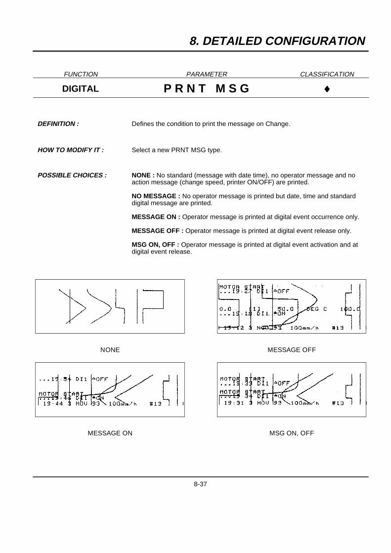
8. DETAILED CONFIGURATION
FUNCTION PARAMETER CLASSIFICATION
DIGITAL P R N T M S G }
DEFINITION : Defines the condition to print the message on Change.
HOW TO MODIFY IT : Select a new PRNT MSG type.
POSSIBLE CHOICES : NONE : No standard (message with date time), no operator message and noaction message (change speed, printer ON/OFF) are printed.
NO MESSAGE : No operator message is printed but date, time and standarddigital message are printed.
MESSAGE ON : Operator message is printed at digital event occurrence only.
MESSAGE OFF : Operator message is printed at digital event release only.
MSG ON, OFF : Operator message is printed at digital event activation and atdigital event release.
NONE
MESSAGE ON
MESSAGE OFF
MSG ON, OFF
8-37

8. DETAILED CONFIGURATION
FUNCTION PARAMETER CLASSIFICATION
DIGITAL T R A C E }}
DEFINITION : Enable/disable the trace of the event.
POSSIBLE CHOICES : ENABLEDISABLE
FUNCTION PARAMETER CLASSIFICATION
DIGITAL T R C O L O R }}
DEFINITION : Defines color of trace.
HOW TO MODIFY IT : Select a new color.
POSSIBLE CHOICES : PURPLE
RED
BLACK
GREEN
BLUE
BROWN
WARNING : THIS FUNCTION IS ONLY AVAILABLE FOR MULTIPOINT RECORDERS.
8-38
8. DETAILED CONFIGURATION
FUNCTION PARAMETER CLASSIFICATION
DIGITAL R E D T R A C }
DEFINITION : Specify if digital input trace must be printed in red on event.
HOW TO MODIFY IT : Select a new value.
POSSIBLE CHOICES : NOYES
WARNING : If the RED TRAC is selected: do not configure the trace in red as normalprinting.
THIS FUNCTION IS ONLY AVAILABLE FOR MULTIPOINT RECORDERS.
FUNCTION PARAMETER CLASSIFICATION
DIGITAL P O S I T I O N }
DEFINITION : Defines the trace position (open contact) on the chart. (in %)
THE AMPLITUDE OF THE EVENT TRACE CANNOT BE ADJUSTED.
WARNING : THIS FUNCTION IS ONLY AVAILABLE FOR MULTIPOINT RECORDERS.
8-39
8. DETAILED CONFIGURATION
FUNCTION MESSAGES
PARAMETER MESSAGE
FUNCTION PARAMETER CLASSIFICATION
MESSAGES M E S S A G E }}}
DEFINITION : To configure the 1 up to 12 messages (14 characters)
HOW TO MODIFY IT : Enter a text digit by digit with the [ and ] keys
POSSIBLE CHOICES : 14 characters
WARNING : If the message is larger than 14 characters, the last digit takes the place of thefirst one, giving a wrong message.
8-40
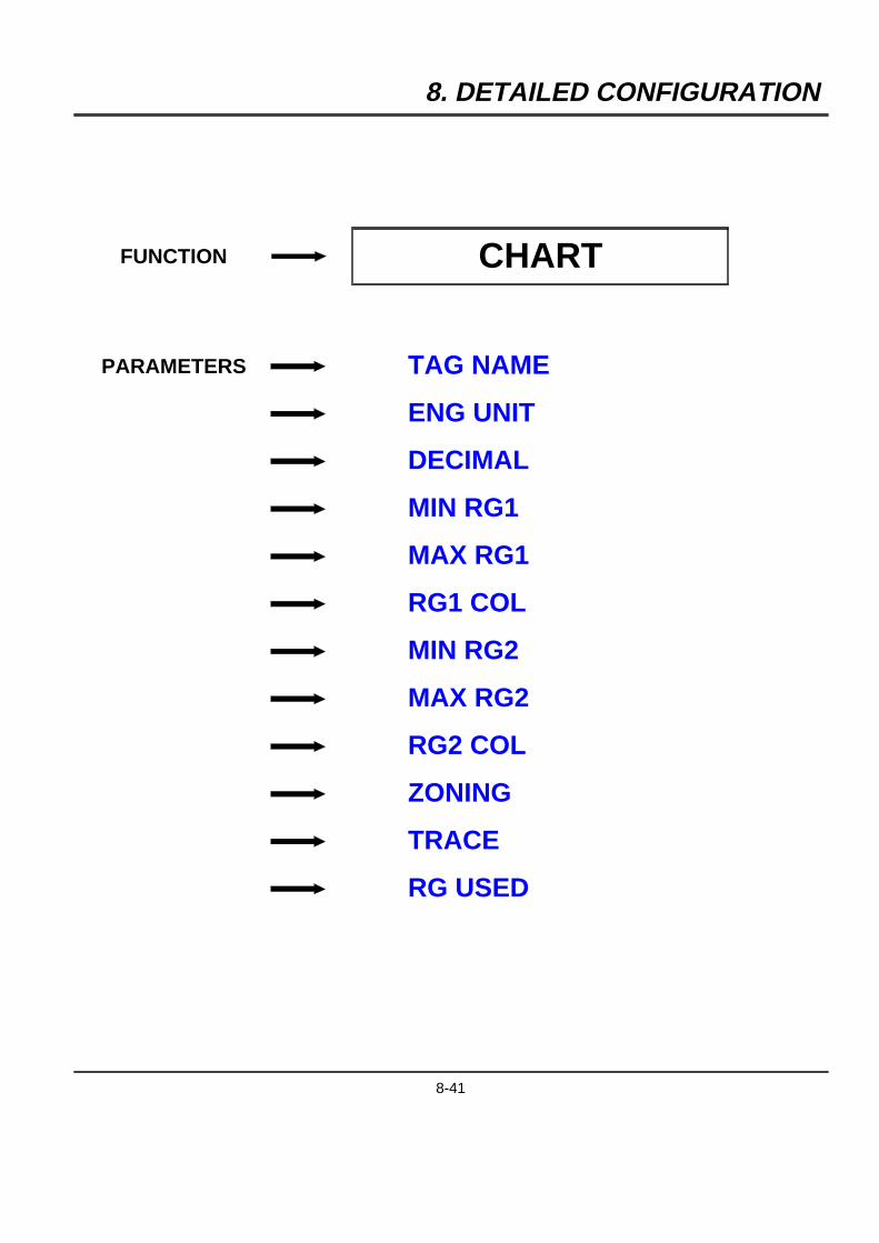
8. DETAILED CONFIGURATION
FUNCTION CHART
PARAMETERS TAG NAME
ENG UNIT
DECIMAL
MIN RG1
MAX RG1
RG1 COL
MIN RG2
MAX RG2
RG2 COL
ZONING
TRACE
RG USED
8-41

8. DETAILED CONFIGURATION
FUNCTION PARAMETER CLASSIFICATION
CHART T A G N A M E }}}
DEFINITION : Tag of name corresponding chart channel.
HOW TO MODIFY IT : Enter a text.
POSSIBLE CHOICES : 8 characters
WARNING : If the message is larger than 8 characters, the last digit takes the place of thefirst one, giving a wrong tag.
FUNCTION PARAMETER CLASSIFICATION
CHART E N G U N I T }}}
DEFINITION : Chart channel units.
HOW TO MODIFY IT : Enter a text
POSSIBLE CHOICES : 5 characters max.
EXAMPLES : - mm/h- ms/mn- Deg F- Deg C- PSI- BAR
8-42
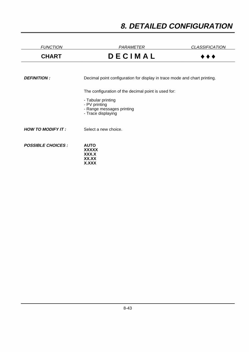
8. DETAILED CONFIGURATION
FUNCTION PARAMETER CLASSIFICATION
CHART D E C I M A L }}}
DEFINITION : Decimal point configuration for display in trace mode and chart printing.
The configuration of the decimal point is used for:
- Tabular printing- PV printing- Range messages printing- Trace displaying
HOW TO MODIFY IT : Select a new choice.
POSSIBLE CHOICES : AUTOXXXXXXXX.XXX.XXX.XXX
8-43
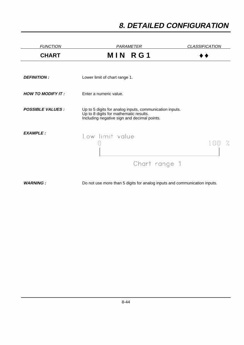
8. DETAILED CONFIGURATION
FUNCTION PARAMETER CLASSIFICATION
CHART M I N R G 1 }}
DEFINITION : Lower limit of chart range 1.
HOW TO MODIFY IT : Enter a numeric value.
POSSIBLE VALUES : Up to 5 digits for analog inputs, communication inputs.Up to 8 digits for mathematic results.Including negative sign and decimal points.
EXAMPLE :
WARNING : Do not use more than 5 digits for analog inputs and communication inputs.
8-44
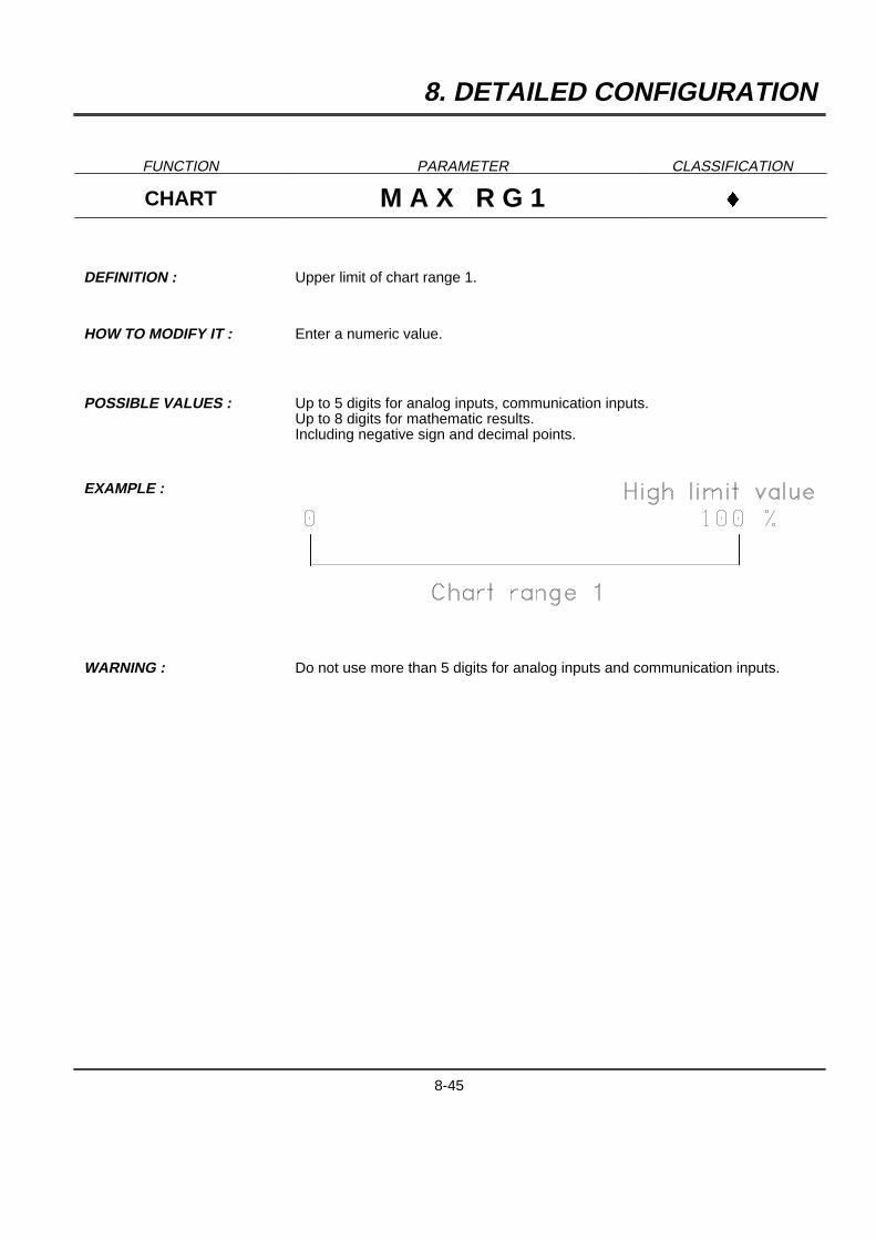
8. DETAILED CONFIGURATION
FUNCTION PARAMETER CLASSIFICATION
CHART M A X R G 1 }
DEFINITION : Upper limit of chart range 1.
HOW TO MODIFY IT : Enter a numeric value.
POSSIBLE VALUES : Up to 5 digits for analog inputs, communication inputs.Up to 8 digits for mathematic results.Including negative sign and decimal points.
EXAMPLE :
WARNING : Do not use more than 5 digits for analog inputs and communication inputs.
8-45
8. DETAILED CONFIGURATION
FUNCTION PARAMETER CLASSIFICATION
CHART R G 1 C O L }
DEFINITION : Color of range 1
HOW TO MODIFY IT : Select a new color.
POSSIBLE CHOICES : PURPLE
RED
BLACK
GREEN
BLUE
BROWN
WARNING : THIS FUNCTION IS ONLY AVAILABLE FOR MULTIPOINT RECORDERS.
8-46
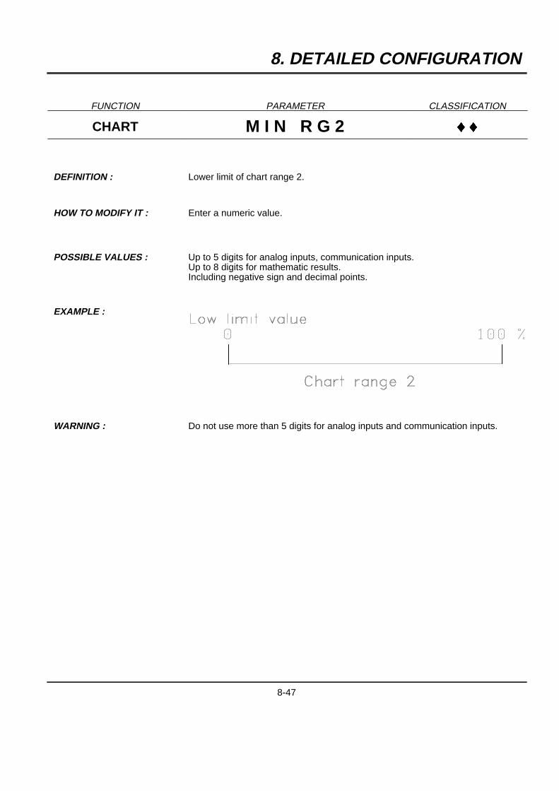
8. DETAILED CONFIGURATION
FUNCTION PARAMETER CLASSIFICATION
CHART M I N R G 2 }}
DEFINITION : Lower limit of chart range 2.
HOW TO MODIFY IT : Enter a numeric value.
POSSIBLE VALUES : Up to 5 digits for analog inputs, communication inputs.Up to 8 digits for mathematic results.Including negative sign and decimal points.
EXAMPLE :
WARNING : Do not use more than 5 digits for analog inputs and communication inputs.
8-47
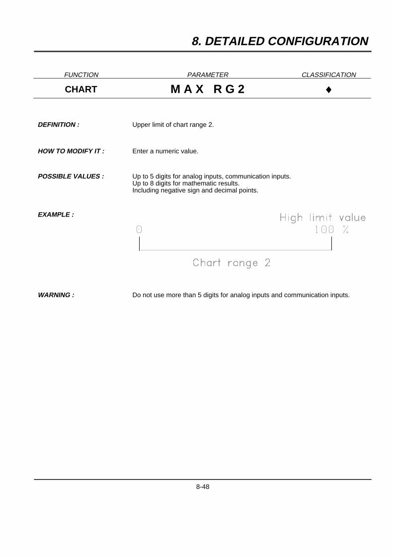
8. DETAILED CONFIGURATION
FUNCTION PARAMETER CLASSIFICATION
CHART M A X R G 2 }
DEFINITION : Upper limit of chart range 2.
HOW TO MODIFY IT : Enter a numeric value.
POSSIBLE VALUES : Up to 5 digits for analog inputs, communication inputs.Up to 8 digits for mathematic results.Including negative sign and decimal points.
EXAMPLE :
WARNING : Do not use more than 5 digits for analog inputs and communication inputs.
8-48

8. DETAILED CONFIGURATION
FUNCTION PARAMETER CLASSIFICATION
CHART R G 2 C O L }
DEFINITION : Color of range 2
HOW TO MODIFY IT : Select a new color.
POSSIBLE CHOICES : PURPLE
RED
BLACK
GREEN
BLUE
BROWN
WARNING : THIS FUNCTION IS ONLY AVAILABLE FOR MULTIPOINT RECORDERS.
8-49
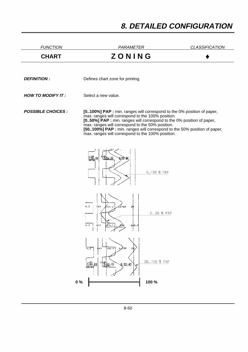
8. DETAILED CONFIGURATION
FUNCTION PARAMETER CLASSIFICATION
CHART Z O N I N G }
DEFINITION : Defines chart zone for printing.
HOW TO MODIFY IT : Select a new value.
POSSIBLE CHOICES : [0..100%] PAP : min. ranges will correspond to the 0% position of paper,max. ranges will correspond to the 100% position.[0..50%] PAP : min. ranges will correspond to the 0% position of paper,max. ranges will correspond to the 50% position.[50..100%] PAP : min. ranges will correspond to the 50% position of paper,max. ranges will correspond to the 100% position.
0 % 100 %
8-50
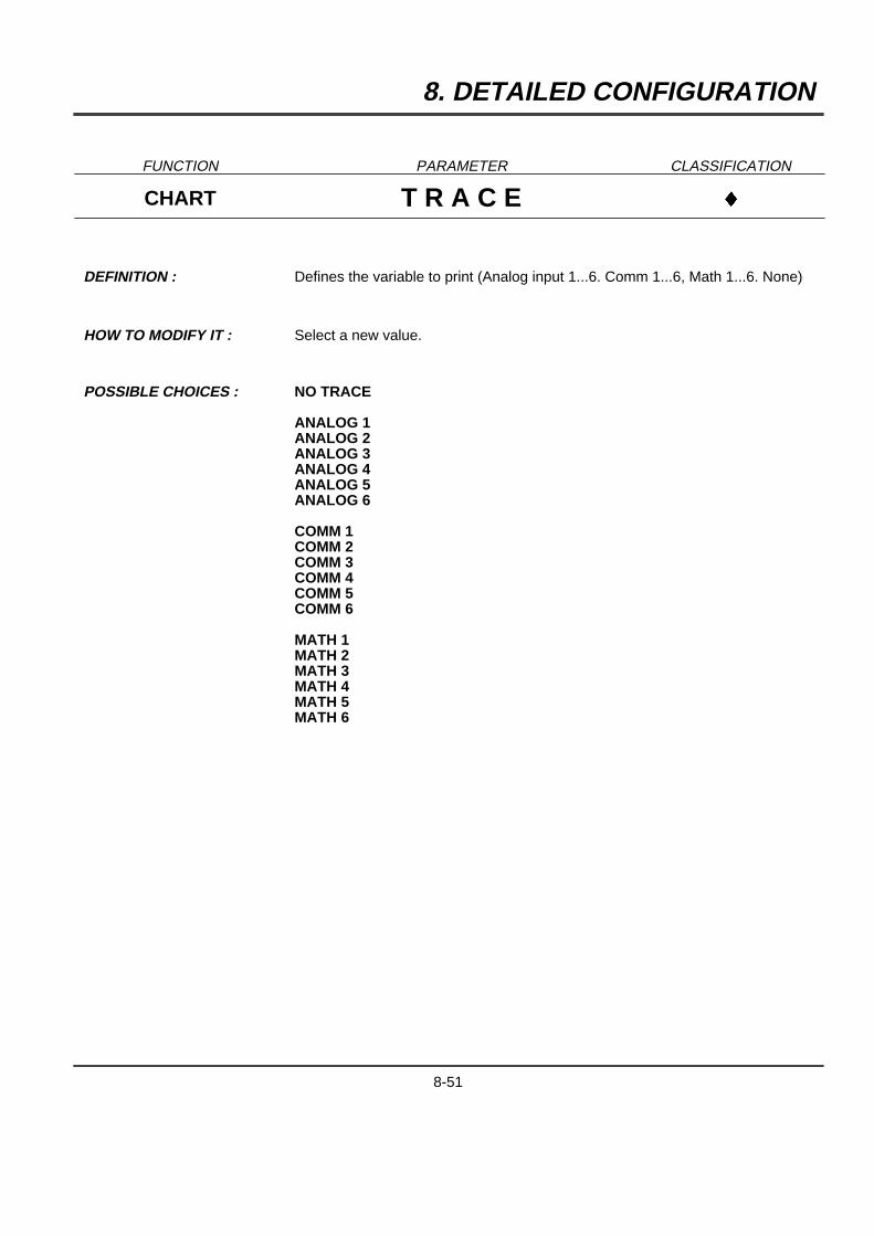
8. DETAILED CONFIGURATION
FUNCTION PARAMETER CLASSIFICATION
CHART T R A C E }
DEFINITION : Defines the variable to print (Analog input 1...6. Comm 1...6, Math 1...6. None)
HOW TO MODIFY IT : Select a new value.
POSSIBLE CHOICES : NO TRACE
ANALOG 1ANALOG 2ANALOG 3ANALOG 4ANALOG 5ANALOG 6
COMM 1COMM 2COMM 3COMM 4COMM 5COMM 6
MATH 1MATH 2MATH 3MATH 4MATH 5MATH 6
8-51
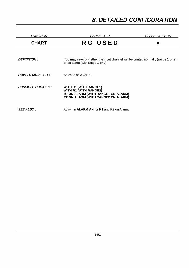
8. DETAILED CONFIGURATION
FUNCTION PARAMETER CLASSIFICATION
CHART R G U S E D }
DEFINITION : You may select whether the input channel will be printed normally (range 1 or 2)or on alarm (with range 1 or 2)
HOW TO MODIFY IT : Select a new value.
POSSIBLE CHOICES : WITH R1 (WITH RANGE1)WITH R2 (WITH RANGE2)R1 ON ALARM (WITH RANGE1 ON ALARM)R2 ON ALARM (WITH RANGE2 ON ALARM)
SEE ALSO : Action in ALARM AN for R1 and R2 on Alarm.
8-52
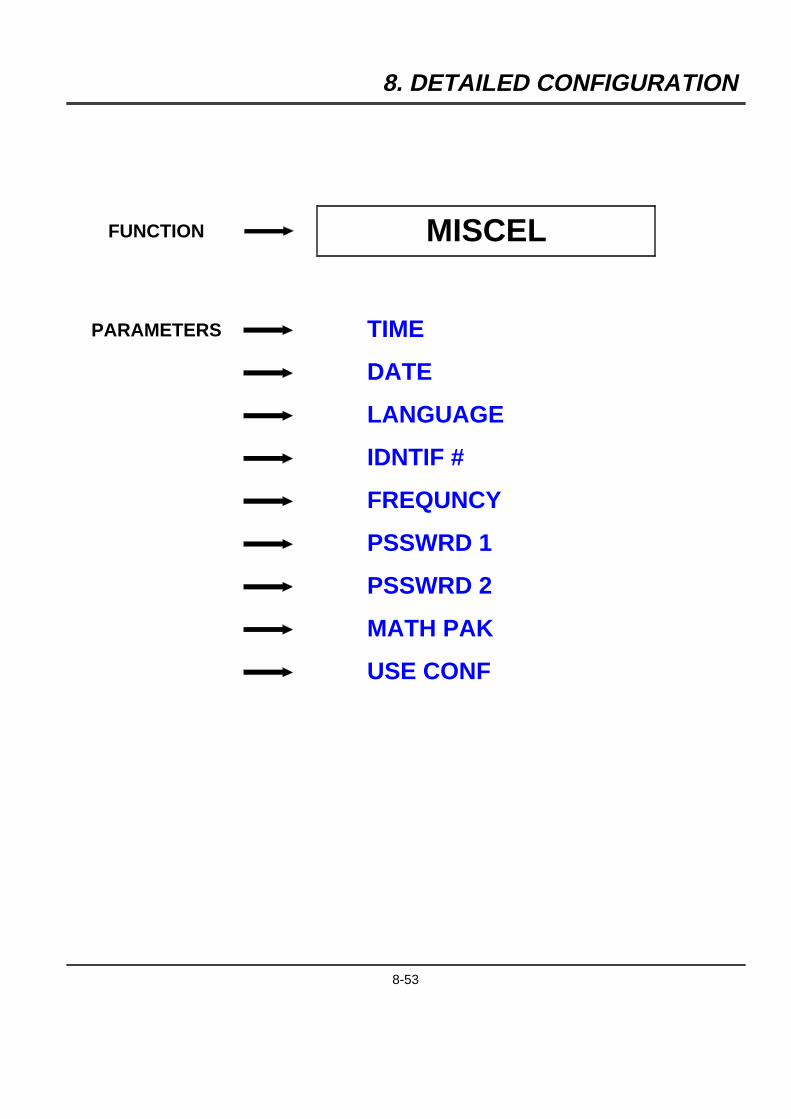
8. DETAILED CONFIGURATION
FUNCTION MISCEL
PARAMETERS TIME
DATE
LANGUAGE
IDNTIF #
FREQUNCY
PSSWRD 1
PSSWRD 2
MATH PAK
USE CONF
8-53
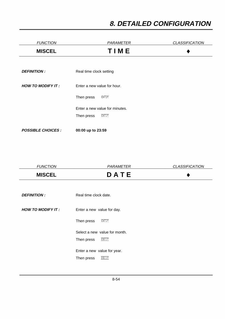
8. DETAILED CONFIGURATION
FUNCTION PARAMETER CLASSIFICATION
MISCEL T I M E }
DEFINITION : Real time clock setting
HOW TO MODIFY IT : Enter a new value for hour.
Then pressAYB
Enter a new value for minutes.
Then pressAYB
POSSIBLE CHOICES : 00:00 up to 23:59
FUNCTION PARAMETER CLASSIFICATION
MISCEL D A T E }
DEFINITION : Real time clock date.
HOW TO MODIFY IT : Enter a new value for day.
Then pressAYB
Select a new value for month.
Then pressAYB
Enter a new value for year.
Then pressAYB
8-54

8. DETAILED CONFIGURATION
FUNCTION PARAMETER CLASSIFICATION
MISCEL L A N G U A G E }}}
DEFINITION : Operator information and configuration language.
HOW TO MODIFY IT : Select a new language
POSSIBLE CHOICES : ENGLISH
FRENCH
GERMAN
SPANISH
ITALIAN
SWEDISH
FUNCTION PARAMETER CLASSIFICATION
MISCEL I D N T I F # }}
DEFINITION : Identification number of the instrument which will be printed on the chart.
HOW TO MODIFY IT : Enter a numeric value.
POSSIBLE VALUES : [0 ... 99]
8-55

8. DETAILED CONFIGURATION
FUNCTION PARAMETER CLASSIFICATION
MISCEL F R E Q U N C Y }
DEFINITION : To select the line frequency.
HOW TO MODIFY IT : Select a new frequency.
POSSIBLE CHOICES : 50 Hz60 Hz
NOTE : This value is important to improve serial mode rejection at power supplyfrequency.
In case of DC power supply, use the line frequency of the country.
8-56

8. DETAILED CONFIGURATION
FUNCTION PARAMETER CLASSIFICATION
MISCEL P S S W R D 1 }
DEFINITION : Used to provide a limited access to configuration.
HOW TO MODIFY IT : Enter a text.
POSSIBLE CHOICES : 8 digits max.
SEE ALSO : See section 6.1 and the classification in section 7.1.
NOTE : The instrument is shipped with password #1 = blank (No entry)This gives a full access to configuration. (No protection)
WARNING : If PSSWRD #1 = PSSWRD #2,the password will be understood as PSSWRD #2.
If PSSWRD#1 = PSSWRD#2 = blank, no password will be asked forconfiguration access.
Do not lose your password code. If yes, you have to contact your servicedepartment.
8-57

8. DETAILED CONFIGURATION
FUNCTION PARAMETER CLASSIFICATION
MISCEL P S S W R D 2 }
DEFINITION : Used to provide full access to configuration.
HOW TO MODIFY IT : Enter a text.
POSSIBLE CHOICES : 8 digits max.
SEE ALSO : See section 6.1 and the classification in section 7.1.
NOTE : The instrument is shipped with password #2 = blank (No entry)This gives a full access to configuration. (No protection)
WARNING : If PSSWRD #2 = PSSWRD #1,the password will be understood as PSSWRD #2.
If PSSWRD#2 = PSSWRD#1 = blank, no password will be asked forconfiguration access.
Do not lose your password code. If yes, you have to contact your servicedepartment.
8-58

8. DETAILED CONFIGURATION
FUNCTION PARAMETER CLASSIFICATION
MISCEL M A T H P A K }
DEFINITION : Type of optional math package
HOW TO MODIFY IT : Enter a code.
POSSIBLE CHOICES : Up to 12 digits
SEE ALSO : SEE MATH USER'S MANUAL
WARNING : This code should be delivered by your service department and is specific to thisrecorder.
To obtain a new code, please indicate the full serial number displayed on MMI.(See the section 9 "SERVICE" on page 9 -16)
FUNCTION PARAMETER CLASSIFICATION
MISCEL U S E C O N F }
DEFINITION : Selection of the desired configuration number.
HOW TO MODIFY IT : Select the configuration number.
POSSIBLE CHOICES : CONF ONE
CONF TWO
NOTE : When CONF # changes, the previous configuration is automatically saved.
8-59
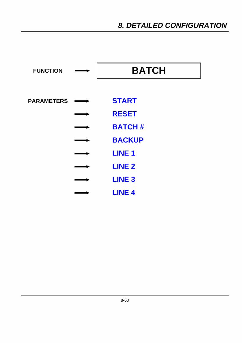
8. DETAILED CONFIGURATION
FUNCTION BATCH
PARAMETERS START
RESET
BATCH #
BACKUP
LINE 1
LINE 2
LINE 3
LINE 4
8-60
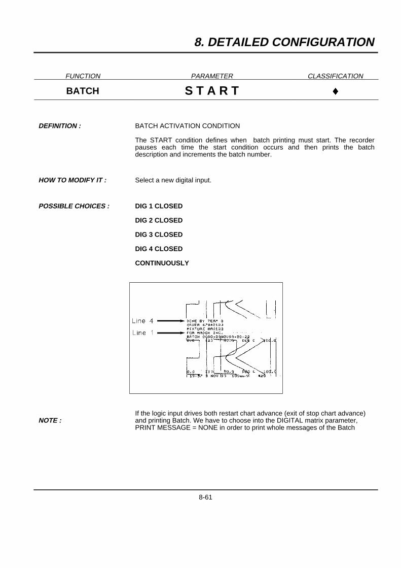
8. DETAILED CONFIGURATION
FUNCTION PARAMETER CLASSIFICATION
BATCH S T A R T }
DEFINITION : BATCH ACTIVATION CONDITION
The START condition defines when batch printing must start. The recorderpauses each time the start condition occurs and then prints the batchdescription and increments the batch number.
HOW TO MODIFY IT : Select a new digital input.
POSSIBLE CHOICES : DIG 1 CLOSED
DIG 2 CLOSED
DIG 3 CLOSED
DIG 4 CLOSED
CONTINUOUSLY
NOTE :If the logic input drives both restart chart advance (exit of stop chart advance)and printing Batch. We have to choose into the DIGITAL matrix parameter,PRINT MESSAGE = NONE in order to print whole messages of the Batch
8-61
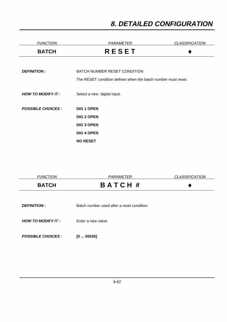
8. DETAILED CONFIGURATION
FUNCTION PARAMETER CLASSIFICATION
BATCH R E S E T }
DEFINITION : BATCH NUMBER RESET CONDITION
The RESET condition defines when the batch number must reset.
HOW TO MODIFY IT : Select a new digital input.
POSSIBLE CHOICES : DIG 1 OPEN
DIG 2 OPEN
DIG 3 OPEN
DIG 4 OPEN
NO RESET
FUNCTION PARAMETER CLASSIFICATION
BATCH B A T C H # }
DEFINITION : Batch number used after a reset condition.
HOW TO MODIFY IT : Enter a new value.
POSSIBLE CHOICES : [0 ... 65535]
8-62
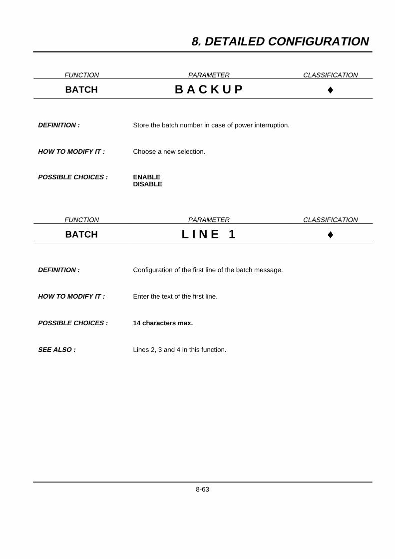
8. DETAILED CONFIGURATION
FUNCTION PARAMETER CLASSIFICATION
BATCH B A C K U P }
DEFINITION : Store the batch number in case of power interruption.
HOW TO MODIFY IT : Choose a new selection.
POSSIBLE CHOICES : ENABLEDISABLE
FUNCTION PARAMETER CLASSIFICATION
BATCH L I N E 1 }
DEFINITION : Configuration of the first line of the batch message.
HOW TO MODIFY IT : Enter the text of the first line.
POSSIBLE CHOICES : 14 characters max.
SEE ALSO : Lines 2, 3 and 4 in this function.
8-63
8. DETAILED CONFIGURATION
FUNCTION PARAMETER CLASSIFICATION
BATCH L I N E 2 }
DEFINITION : Configuration of the second line of the batch message.
HOW TO MODIFY IT : Enter the text of the second line.
POSSIBLE CHOICES : 14 characters
SEE ALSO : Lines 3 and 4 in this function.
FUNCTION PARAMETER CLASSIFICATION
BATCH L I N E 3 }
DEFINITION : Configuration of the third line of the batch message.
HOW TO MODIFY IT : Enter the text of the third line.
POSSIBLE CHOICES : 14 characters.
SEE ALSO : Line 4 in this function.
8-64

8. DETAILED CONFIGURATION
FUNCTION PARAMETER CLASSIFICATION
BATCH L I N E 4 }
DEFINITION : Configuration of the fourth line of the batch message.
HOW TO MODIFY IT : Enter the text of the fourth line.
POSSIBLE CHOICES : 14 characters.
8-65
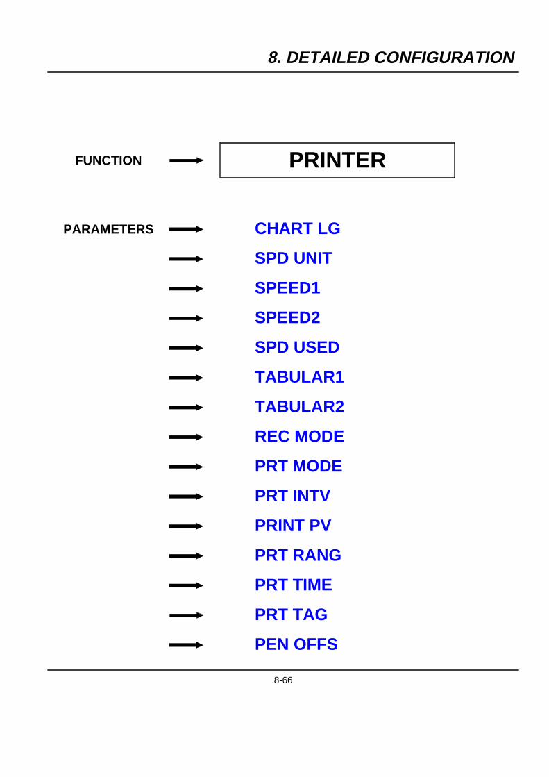
8. DETAILED CONFIGURATION
FUNCTION PRINTER
PARAMETERS CHART LG
SPD UNIT
SPEED1
SPEED2
SPD USED
TABULAR1
TABULAR2
REC MODE
PRT MODE
PRT INTV
PRINT PV
PRT RANG
PRT TIME
PRT TAG
PEN OFFS
8-66
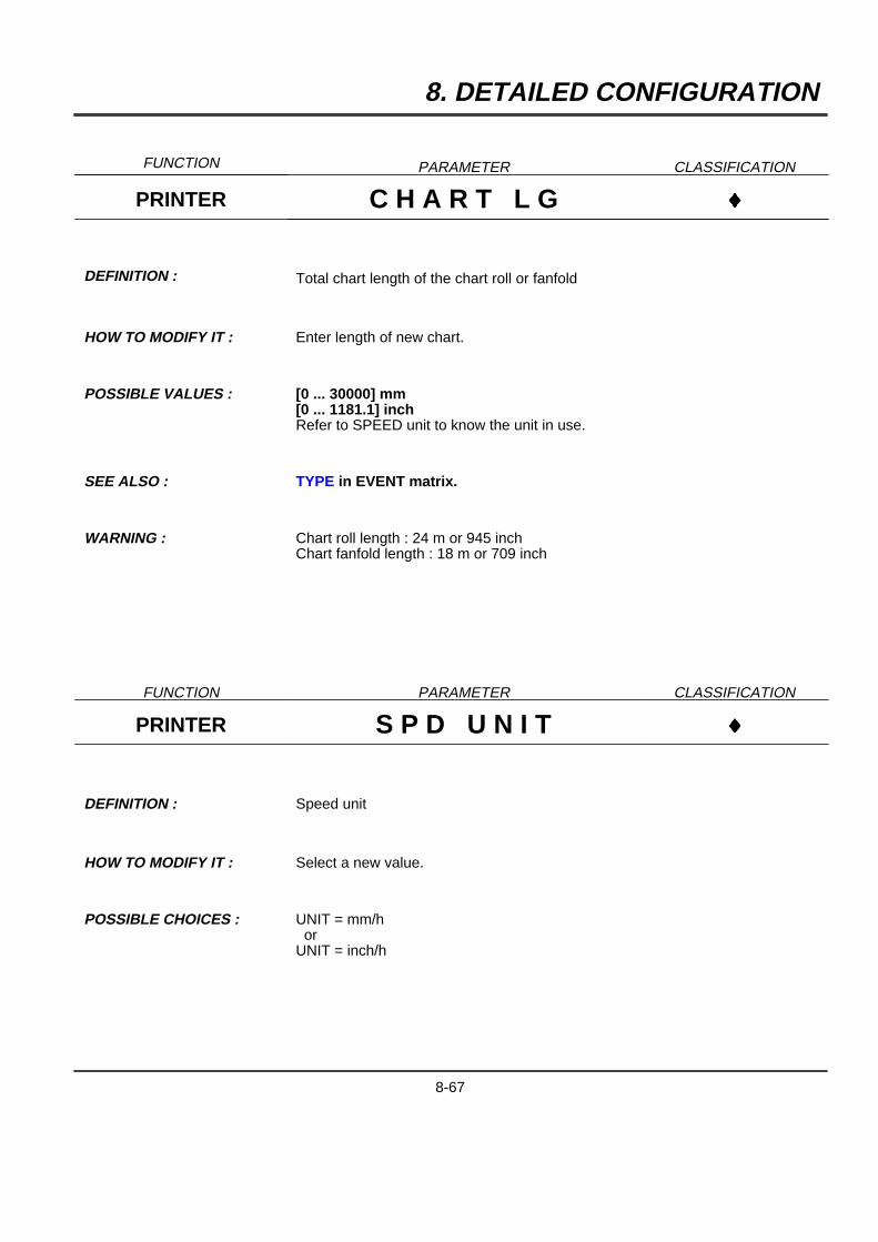
8. DETAILED CONFIGURATION
FUNCTION PARAMETER CLASSIFICATION
PRINTER C H A R T L G }
DEFINITION : Total chart length of the chart roll or fanfold
HOW TO MODIFY IT : Enter length of new chart.
POSSIBLE VALUES : [0 ... 30000] mm[0 ... 1181.1] inchRefer to SPEED unit to know the unit in use.
SEE ALSO : TYPE in EVENT matrix.
WARNING : Chart roll length : 24 m or 945 inchChart fanfold length : 18 m or 709 inch
FUNCTION PARAMETER CLASSIFICATION
PRINTER S P D U N I T }
DEFINITION : Speed unit
HOW TO MODIFY IT : Select a new value.
POSSIBLE CHOICES : UNIT = mm/hor
UNIT = inch/h
8-67
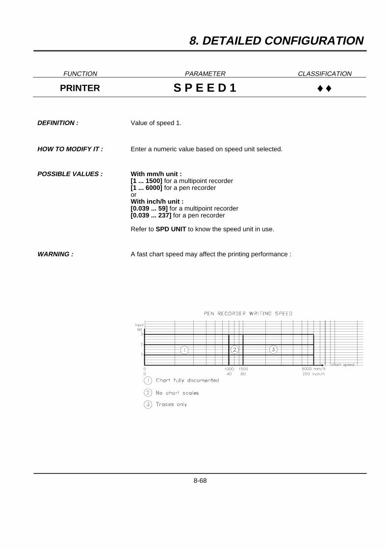
8. DETAILED CONFIGURATION
FUNCTION PARAMETER CLASSIFICATION
PRINTER S P E E D 1 }}
DEFINITION : Value of speed 1.
HOW TO MODIFY IT : Enter a numeric value based on speed unit selected.
POSSIBLE VALUES : With mm/h unit :[1 ... 1500] for a multipoint recorder[1 ... 6000] for a pen recorderorWith inch/h unit :[0.039 ... 59] for a multipoint recorder[0.039 ... 237] for a pen recorder
Refer to SPD UNIT to know the speed unit in use.
WARNING : A fast chart speed may affect the printing performance :
8-68
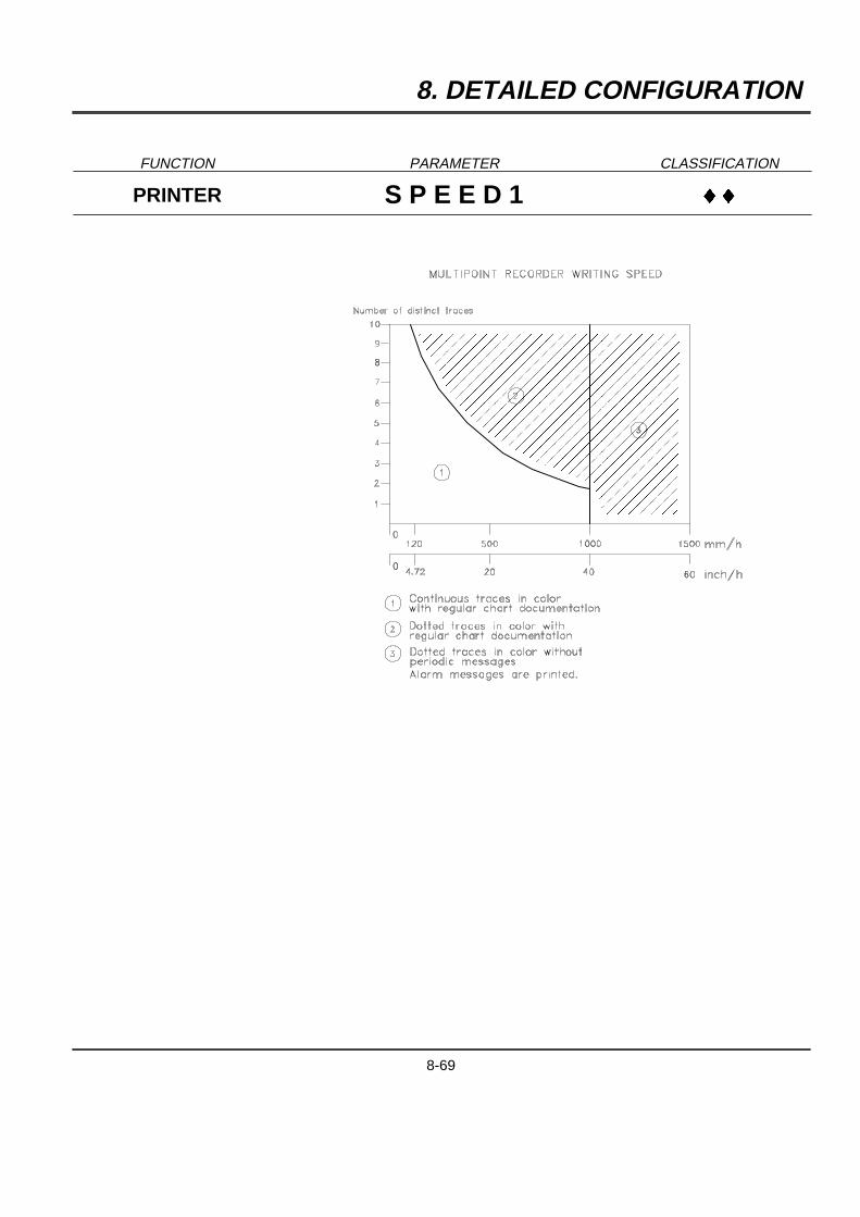
8. DETAILED CONFIGURATION
FUNCTION PARAMETER CLASSIFICATION
PRINTER S P E E D 1 }}
�����������������
�����������������
�����������������
�����������������
�����������������
�����������������
�����������������
�����������������
�����������������
�����������������
�����������������
�����������������
�����������������
�����������������
�����������������
�����������������
�����������������
�����������������
�����������������
�����������������
�����������������
�����������������
�����������������
�����������������
8-69

8. DETAILED CONFIGURATION
FUNCTION PARAMETER CLASSIFICATION
PRINTER S P E E D 2 }
DEFINITION : Value of speed 2.
HOW TO MODIFY IT : Enter a numeric value based on speed unit selected.
POSSIBLE VALUES : With mm/h unit :[1 ... 1500] for a multipoint recorder[1 ... 6000] for a pen recorderorWith inch/h unit :[0.039 ... 59] for a multipoint recorder[0.039 ... 237] for a pen recorder
Refer to SPD UNIT to know the speed unit in use.
WARNING : A fast chart speed may affect the printing performance :
8-70
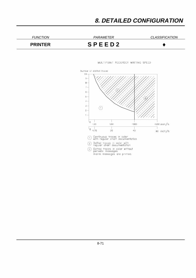
8. DETAILED CONFIGURATION
FUNCTION PARAMETER CLASSIFICATION
PRINTER S P E E D 2 }
�����������������
�����������������
�����������������
�����������������
�����������������
�����������������
�����������������
�����������������
�����������������
�����������������
�����������������
�����������������
�����������������
�����������������
�����������������
�����������������
�����������������
�����������������
�����������������
�����������������
�����������������
�����������������
�����������������
�����������������
8-71

8. DETAILED CONFIGURATION
FUNCTION PARAMETER CLASSIFICATION
PRINTER S P D U S E D }
DEFINITION : Defines speed in use.
HOW TO MODIFY IT : Select a new speed.
POSSIBLE CHOICES : SPEED 1 USEDSPEED 2 USED
NOTE : If printing mode (PRT MODE) is TABULAR,SPEED 1, SPEED 2 must be understood as TABULAR 1, TABULAR 2.
8-72
8. DETAILED CONFIGURATION
FUNCTION PARAMETER CLASSIFICATION
PRINTER T A B U L A R 1 }
DEFINITION : Tab 1 prints interval. (In minute)
HOW TO MODIFY IT : Select a new time.
POSSIBLE CHOICES : 10 mn20 mn30 mn1 Hour2 Hours3 Hours4 Hours8 Hours24 Hours
SEE ALSO : PRT MODE in this function.
WARNING : THIS FUNCTION IS ONLY AVAILABLE FOR MULTIPOINT RECORDERS.
8-73
8. DETAILED CONFIGURATION
FUNCTION PARAMETER CLASSIFICATION
PRINTER T A B U L A R 2 }
DEFINITION : Tab 2 prints interval.
HOW TO MODIFY IT : Select a new time.
POSSIBLE CHOICES : 10 mn20 mn30 mn1 Hour2 Hours3 Hours4 Hours8 Hours24 Hours
SEE ALSO : PRT MODE in this function.
WARNING : THIS FUNCTION IS ONLY AVAILABLE FOR MULTIPOINT RECORDERS.
8-74
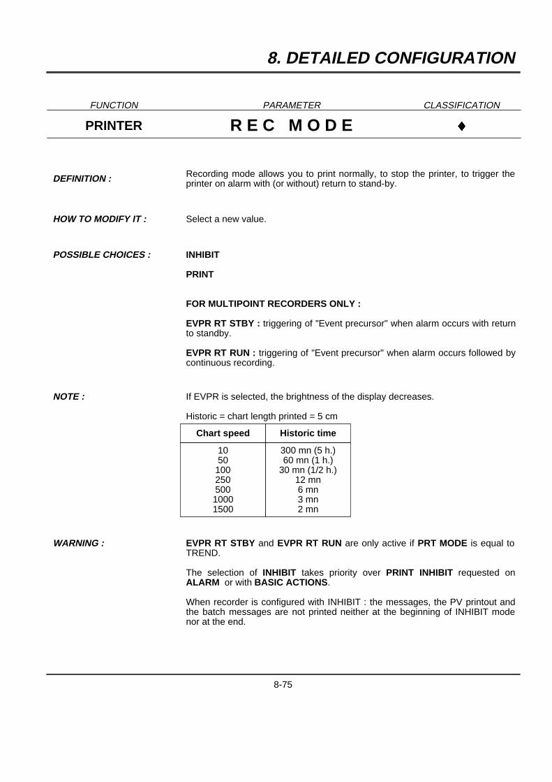
8. DETAILED CONFIGURATION
FUNCTION PARAMETER CLASSIFICATION
PRINTER R E C M O D E }
DEFINITION : Recording mode allows you to print normally, to stop the printer, to trigger theprinter on alarm with (or without) return to stand-by.
HOW TO MODIFY IT : Select a new value.
POSSIBLE CHOICES : INHIBIT
FOR MULTIPOINT RECORDERS ONLY :
EVPR RT STBY : triggering of "Event precursor" when alarm occurs with returnto standby.
EVPR RT RUN : triggering of "Event precursor" when alarm occurs followed bycontinuous recording.
NOTE : If EVPR is selected, the brightness of the display decreases.
Historic = chart length printed = 5 cm
Chart speed Historic time
1050
10025050010001500
300 mn (5 h.)60 mn (1 h.)
30 mn (1/2 h.)12 mn6 mn3 mn2 mn
WARNING : EVPR RT STBY and EVPR RT RUN are only active if PRT MODE is equal toTREND.
The selection of INHIBIT takes priority over PRINT INHIBIT requested onALARM or with BASIC ACTIONS.
When recorder is configured with INHIBIT : the messages, the PV printout andthe batch messages are not printed neither at the beginning of INHIBIT modenor at the end.
8-75

8. DETAILED CONFIGURATION
FUNCTION PARAMETER CLASSIFICATION
PRINTER P R T M O D E }}
DEFINITION : Under this heading you must choose whether recording will be in trend mode ortabular mode.
HOW TO MODIFY IT : Select a new printing mode.
POSSIBLE CHOICES : TREND : All channels recorded as trends.
TABULAR : All channels recorded in tabular format.
SEE ALSO : REC MODE for compatibility with EVENT PERCURSOR.
WARNING : THIS FUNCTION IS ONLY AVAILABLE FOR MULTIPOINT RECORDERS.
8-76

8. DETAILED CONFIGURATION
FUNCTION PARAMETER CLASSIFICATION
PRINTER P R T I N T V }
DEFINITION : Separation (in millimeters) of PRT PV interval for periodic printing.
HOW TO MODIFY IT : Select a new printing interval.
POSSIBLE CHOICES : 60 mm
120 mm
240 mm
480 mm
NOTE : The distance between 2 periodic chart documentation is approximate.The software will print at the round time as closest as possible to the selecteddistance value.
Between the periodic printing of PV, chart ranges informations and speed/timeinformations may be printed if they are selected and if PRT INTV is larger than60 mm.
8-77
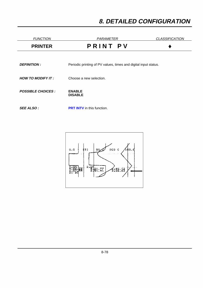
8. DETAILED CONFIGURATION
FUNCTION PARAMETER CLASSIFICATION
PRINTER P R I N T P V }
DEFINITION : Periodic printing of PV values, times and digital input status.
HOW TO MODIFY IT : Choose a new selection.
POSSIBLE CHOICES : ENABLEDISABLE
SEE ALSO : PRT INTV in this function.
8-78
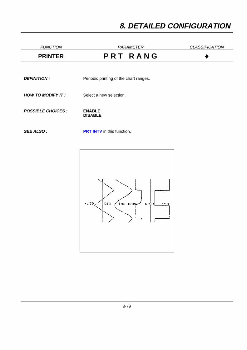
8. DETAILED CONFIGURATION
FUNCTION PARAMETER CLASSIFICATION
PRINTER P R T R A N G }
DEFINITION : Periodic printing of the chart ranges.
HOW TO MODIFY IT : Select a new selection.
POSSIBLE CHOICES : ENABLEDISABLE
SEE ALSO : PRT INTV in this function.
8-79
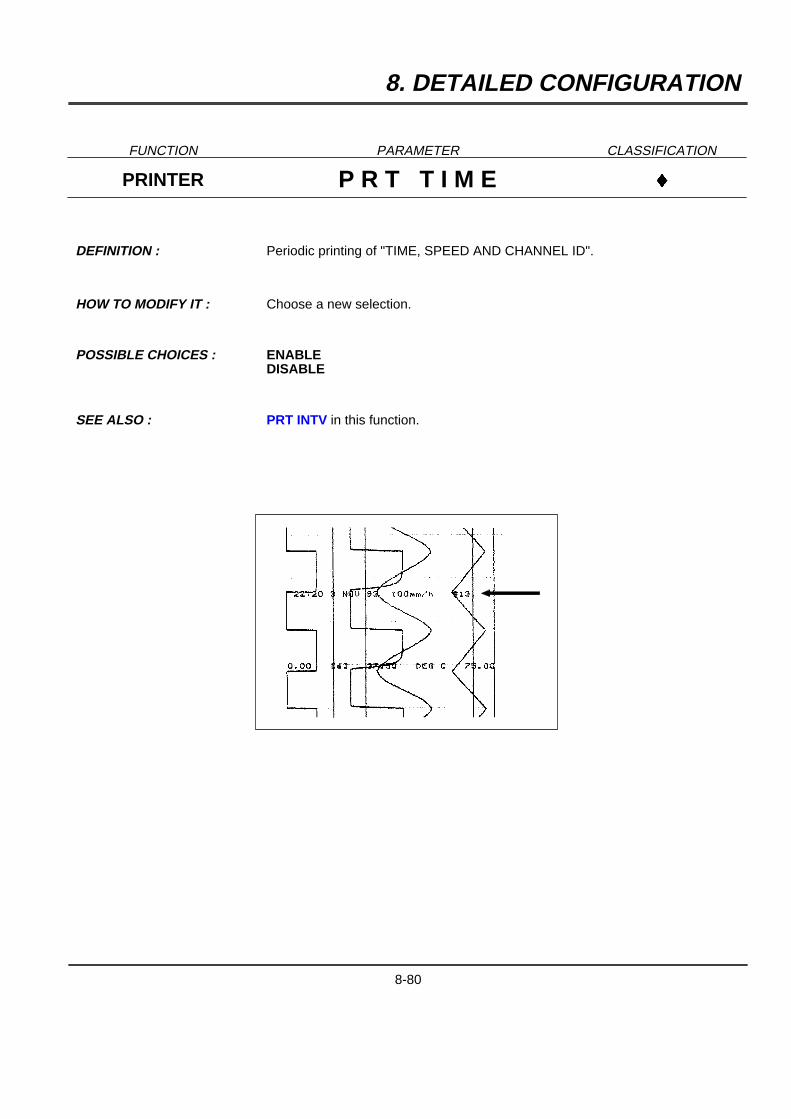
8. DETAILED CONFIGURATION
FUNCTION PARAMETER CLASSIFICATION
PRINTER P R T T I M E }
DEFINITION : Periodic printing of "TIME, SPEED AND CHANNEL ID".
HOW TO MODIFY IT : Choose a new selection.
POSSIBLE CHOICES : ENABLEDISABLE
SEE ALSO : PRT INTV in this function.
8-80
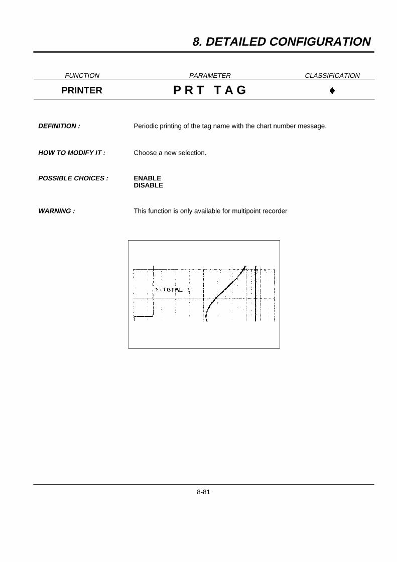
8. DETAILED CONFIGURATION
FUNCTION PARAMETER CLASSIFICATION
PRINTER P R T T A G }
DEFINITION : Periodic printing of the tag name with the chart number message.
HOW TO MODIFY IT : Choose a new selection.
POSSIBLE CHOICES : ENABLEDISABLE
WARNING : This function is only available for multipoint recorder
8-81
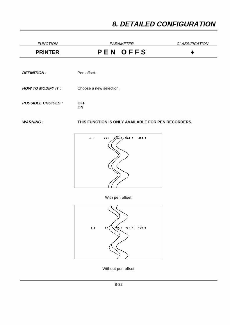
8. DETAILED CONFIGURATION
FUNCTION PARAMETER CLASSIFICATION
PRINTER P E N O F F S }
DEFINITION : Pen offset.
HOW TO MODIFY IT : Choose a new selection.
POSSIBLE CHOICES : OFFON
WARNING : THIS FUNCTION IS ONLY AVAILABLE FOR PEN RECORDERS.
With pen offset
Without pen offset
8-82
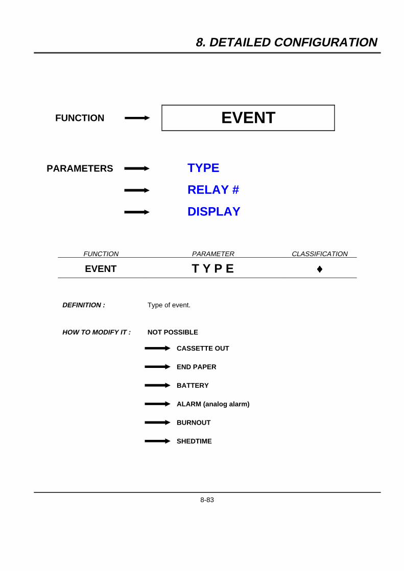
8. DETAILED CONFIGURATION
FUNCTION EVENT
PARAMETERS TYPE
RELAY #
DISPLAY
FUNCTION PARAMETER CLASSIFICATION
EVENT T Y P E }
DEFINITION : Type of event.
HOW TO MODIFY IT : NOT POSSIBLE
CASSETTE OUT
END PAPER
BATTERY
ALARM (analog alarm)
BURNOUT
SHEDTIME
8-83
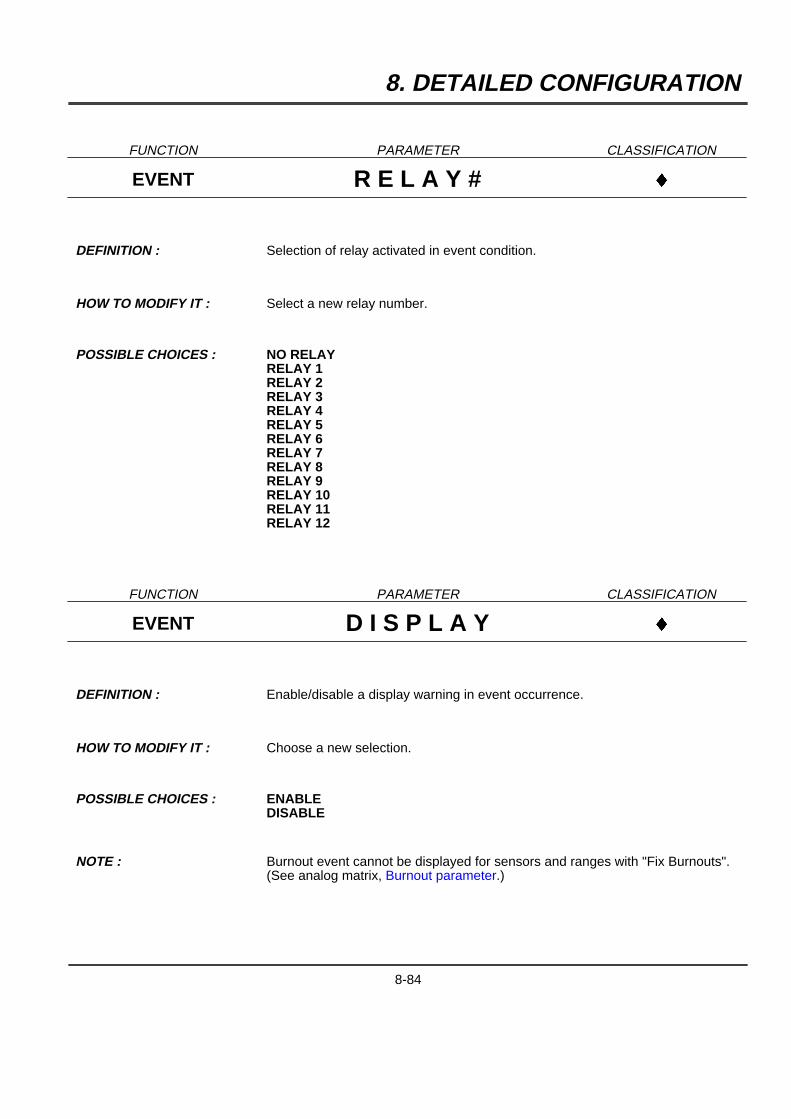
8. DETAILED CONFIGURATION
FUNCTION PARAMETER CLASSIFICATION
EVENT R E L A Y # }
DEFINITION : Selection of relay activated in event condition.
HOW TO MODIFY IT : Select a new relay number.
POSSIBLE CHOICES : NO RELAYRELAY 1RELAY 2RELAY 3RELAY 4RELAY 5RELAY 6RELAY 7RELAY 8RELAY 9RELAY 10RELAY 11RELAY 12
FUNCTION PARAMETER CLASSIFICATION
EVENT D I S P L A Y }
DEFINITION : Enable/disable a display warning in event occurrence.
HOW TO MODIFY IT : Choose a new selection.
POSSIBLE CHOICES : ENABLEDISABLE
NOTE : Burnout event cannot be displayed for sensors and ranges with "Fix Burnouts".(See analog matrix, Burnout parameter.)
8-84
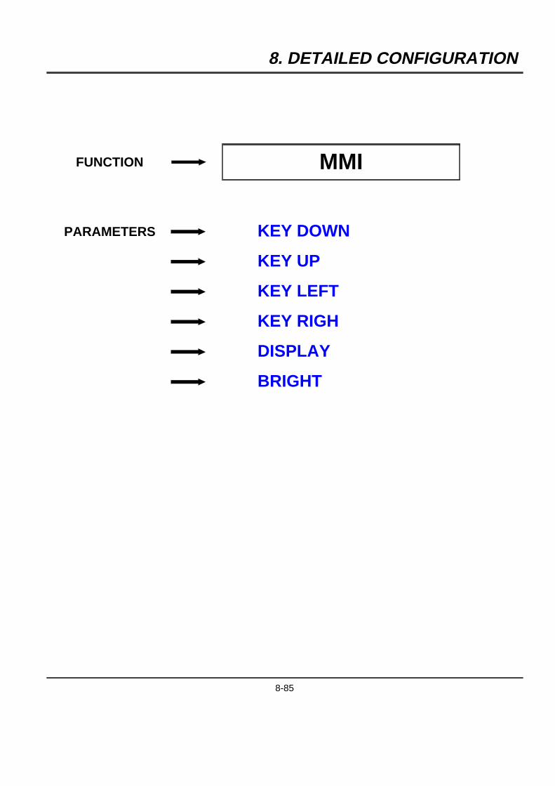
8. DETAILED CONFIGURATION
FUNCTION MMI
PARAMETERS KEY DOWN
KEY UP
KEY LEFT
KEY RIGH
DISPLAY
BRIGHT
8-85
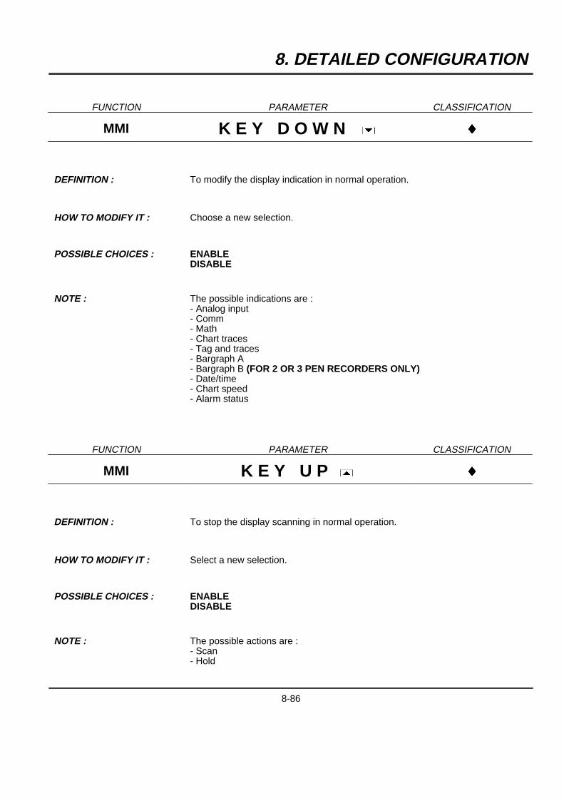
8. DETAILED CONFIGURATION
FUNCTION PARAMETER CLASSIFICATION
MMI K E Y D O W N ] }
DEFINITION : To modify the display indication in normal operation.
HOW TO MODIFY IT : Choose a new selection.
POSSIBLE CHOICES : ENABLEDISABLE
NOTE : The possible indications are :- Analog input- Comm- Math- Chart traces- Tag and traces- Bargraph A- Bargraph B (FOR 2 OR 3 PEN RECORDERS ONLY)- Date/time- Chart speed- Alarm status
FUNCTION PARAMETER CLASSIFICATION
MMI K E Y U P [ }
DEFINITION : To stop the display scanning in normal operation.
HOW TO MODIFY IT : Select a new selection.
POSSIBLE CHOICES : ENABLEDISABLE
NOTE : The possible actions are :- Scan- Hold
8-86
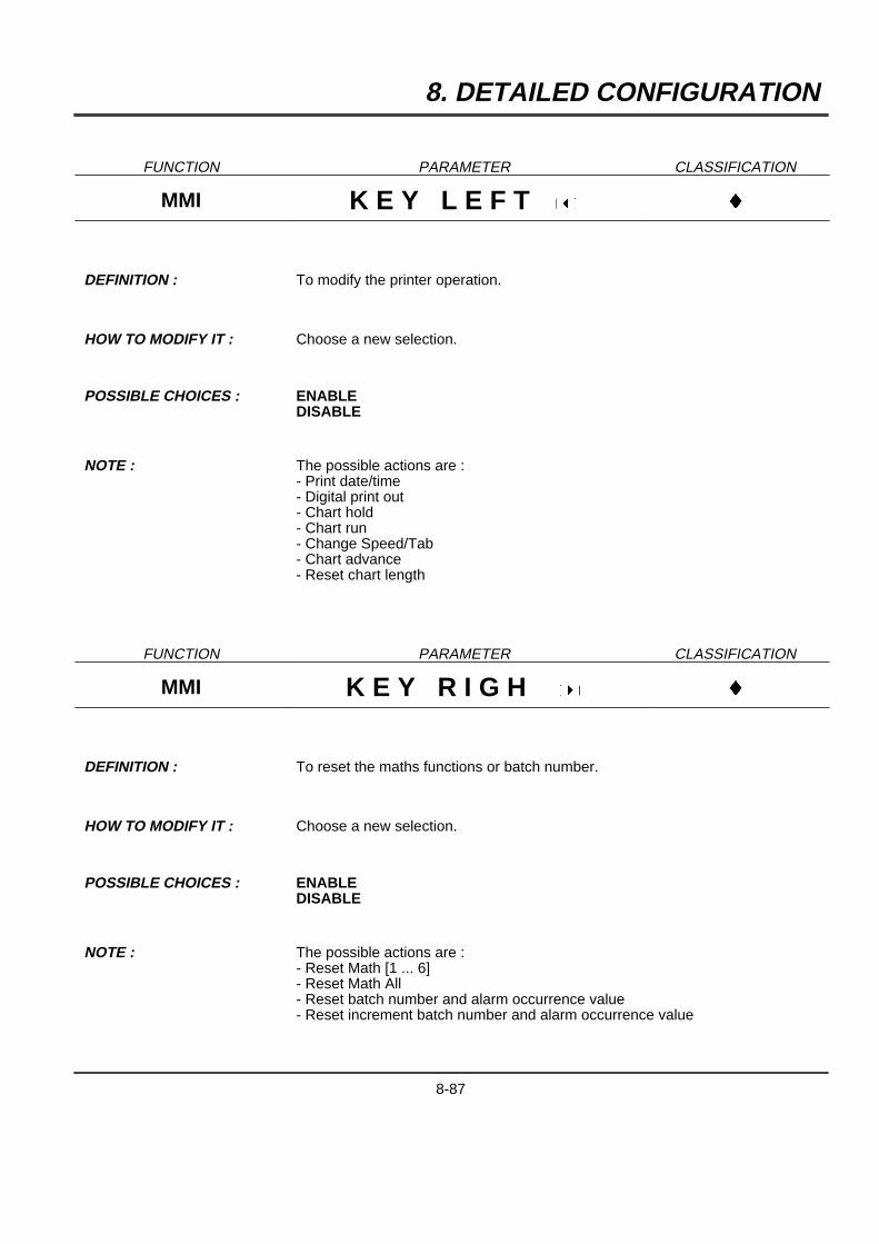
8. DETAILED CONFIGURATION
FUNCTION PARAMETER CLASSIFICATION
MMI K E Y L E F T { }
DEFINITION : To modify the printer operation.
HOW TO MODIFY IT : Choose a new selection.
POSSIBLE CHOICES : ENABLEDISABLE
NOTE : The possible actions are :- Print date/time- Digital print out- Chart hold- Chart run- Change Speed/Tab- Chart advance- Reset chart length
FUNCTION PARAMETER CLASSIFICATION
MMI K E Y R I G H } }
DEFINITION : To reset the maths functions or batch number.
HOW TO MODIFY IT : Choose a new selection.
POSSIBLE CHOICES : ENABLEDISABLE
NOTE : The possible actions are :- Reset Math [1 ... 6]- Reset Math All- Reset batch number and alarm occurrence value- Reset increment batch number and alarm occurrence value
8-87
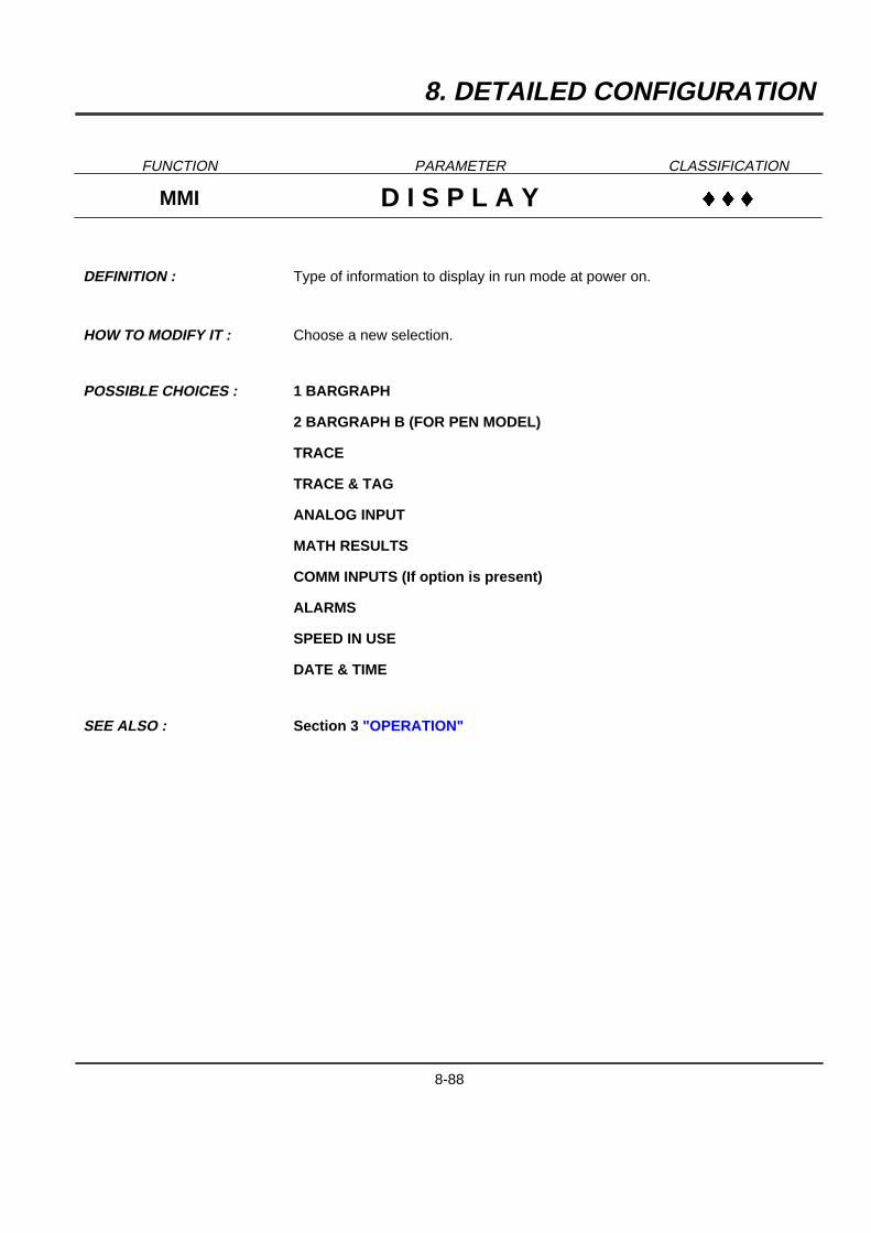
8. DETAILED CONFIGURATION
FUNCTION PARAMETER CLASSIFICATION
MMI D I S P L A Y }}}
DEFINITION : Type of information to display in run mode at power on.
HOW TO MODIFY IT : Choose a new selection.
POSSIBLE CHOICES : 1 BARGRAPH
2 BARGRAPH B (FOR PEN MODEL)
TRACE
TRACE & TAG
ANALOG INPUT
MATH RESULTS
COMM INPUTS (If option is present)
ALARMS
SPEED IN USE
DATE & TIME
SEE ALSO : Section 3 "OPERATION"
8-88

8. DETAILED CONFIGURATION
FUNCTION PARAMETER CLASSIFICATION
MMI B R I G H T }
DEFINITION : To modify the display brightness during operation.
HOW TO MODIFY IT : Choose a new selection.
POSSIBLE CHOICES : OFF (0 %)
>> (20 %)
MEDIUM (40 %)
>> (60 %)
>> (80 %)
HIGH (100 %)
8-89
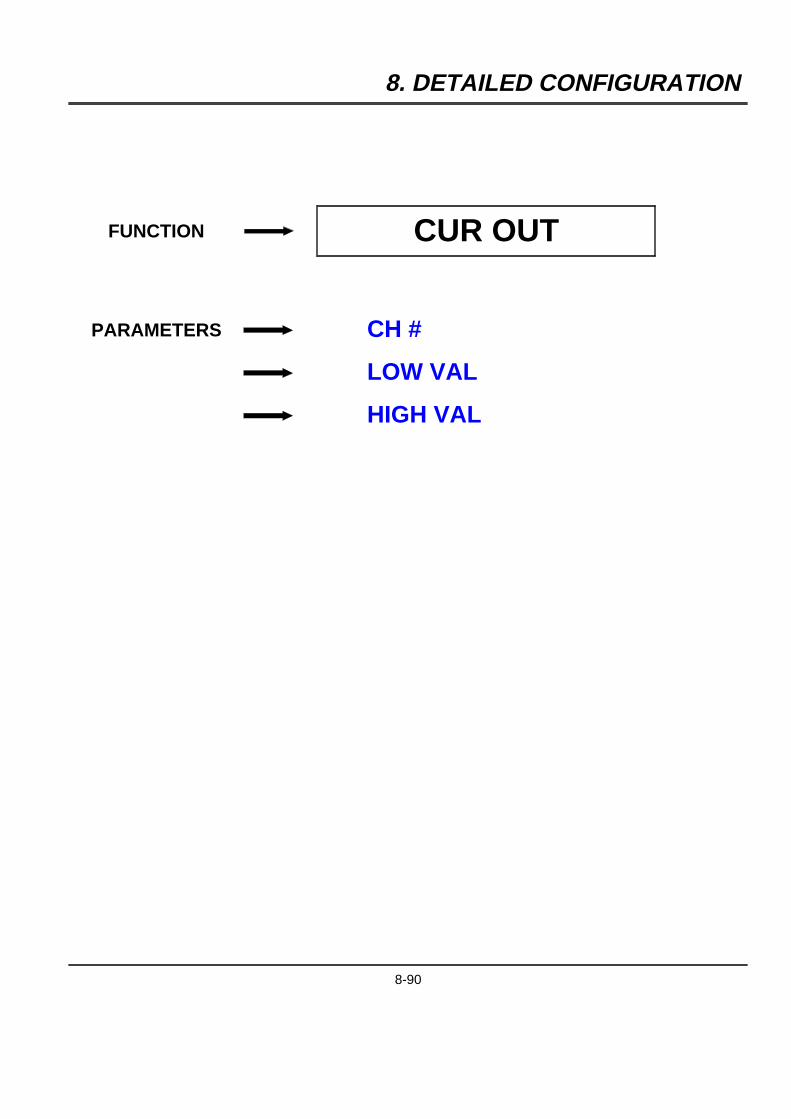
8. DETAILED CONFIGURATION
FUNCTION CUR OUT
PARAMETERS CH #
LOW VAL
HIGH VAL
8-90
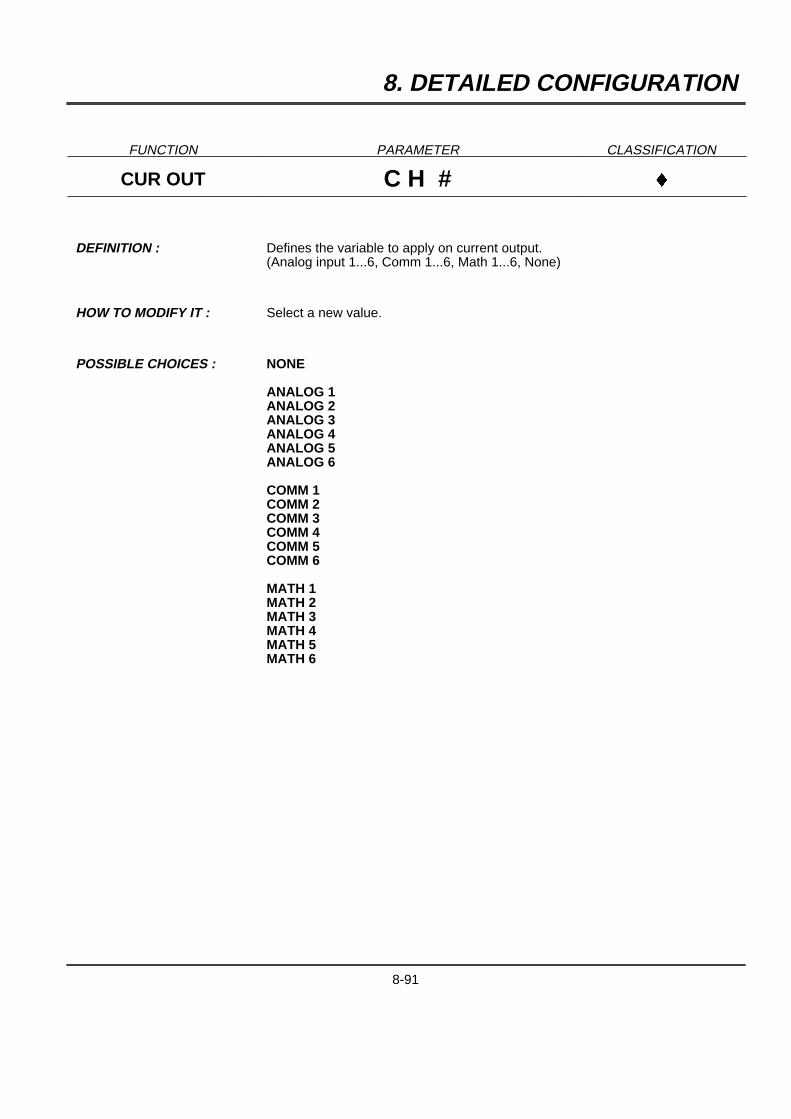
8. DETAILED CONFIGURATION
FUNCTION PARAMETER CLASSIFICATION
CUR OUT C H # }
DEFINITION : Defines the variable to apply on current output.(Analog input 1...6, Comm 1...6, Math 1...6, None)
HOW TO MODIFY IT : Select a new value.
POSSIBLE CHOICES : NONE
ANALOG 1ANALOG 2ANALOG 3ANALOG 4ANALOG 5ANALOG 6
COMM 1COMM 2COMM 3COMM 4COMM 5COMM 6
MATH 1MATH 2MATH 3MATH 4MATH 5MATH 6
8-91
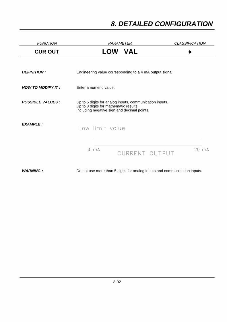
8. DETAILED CONFIGURATION
FUNCTION PARAMETER CLASSIFICATION
CUR OUT LOW VAL }
DEFINITION : Engineering value corresponding to a 4 mA output signal.
HOW TO MODIFY IT : Enter a numeric value.
POSSIBLE VALUES : Up to 5 digits for analog inputs, communication inputs.Up to 8 digits for mathematic results.Including negative sign and decimal points.
EXAMPLE :
WARNING : Do not use more than 5 digits for analog inputs and communication inputs.
8-92
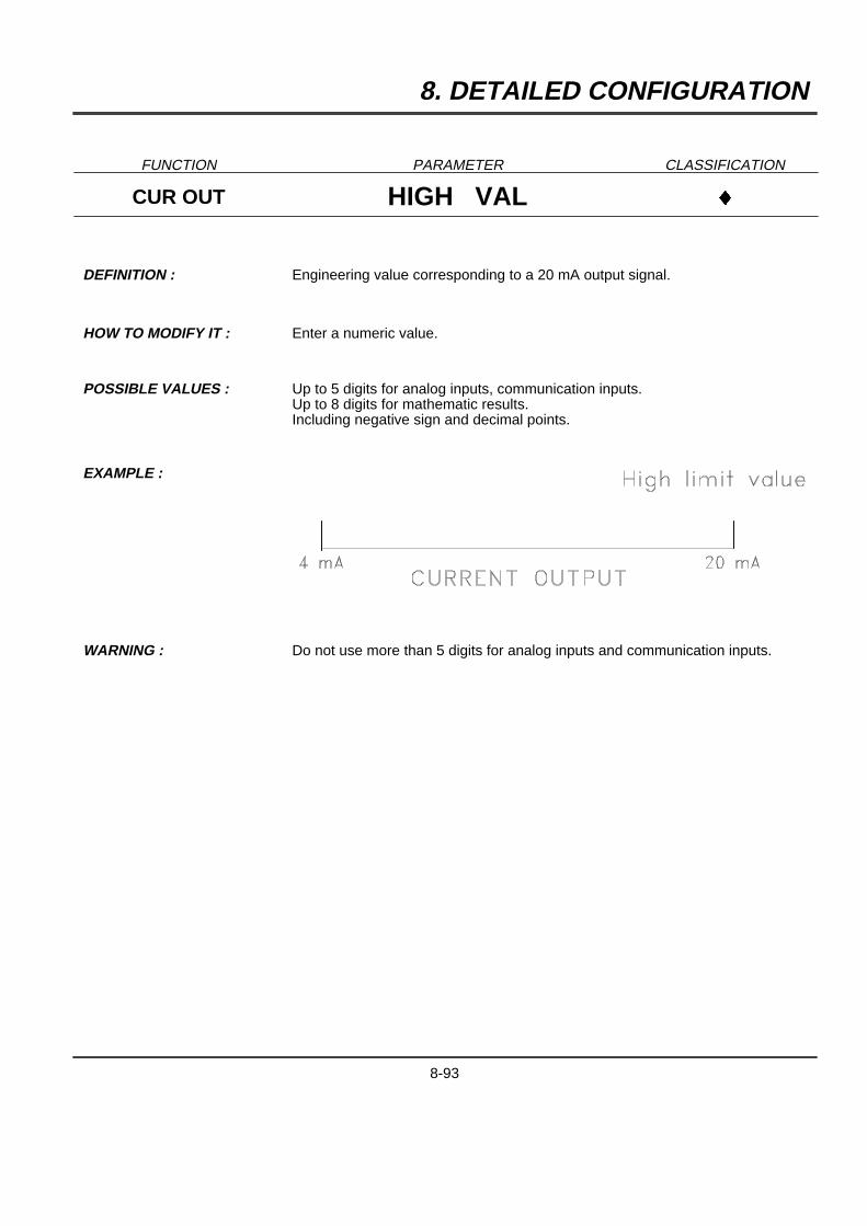
8. DETAILED CONFIGURATION
FUNCTION PARAMETER CLASSIFICATION
CUR OUT HIGH VAL }
DEFINITION : Engineering value corresponding to a 20 mA output signal.
HOW TO MODIFY IT : Enter a numeric value.
POSSIBLE VALUES : Up to 5 digits for analog inputs, communication inputs.Up to 8 digits for mathematic results.Including negative sign and decimal points.
EXAMPLE :
WARNING : Do not use more than 5 digits for analog inputs and communication inputs.
8-93

8. DETAILED CONFIGURATION
8-94

9. SERVICE
9.1 OPERATOR INTERFACE
9.1.1 ACCESS TO SERVICE
Access to Read/Write Configuration (R/W), Print Configuration (PRN) of service (SRV) from Operation mode is
obtained by pressing theAZBkey.
9.1.2 PASSWORDS
To protect the recorder against unauthorized access, the operator has to enter a password. There are twopossible levels of access :
2 Password #1 allows reduced access to service. If password #1 is used, you are able only to adjust the 0 % and100 % chart markings.
2 Password #2 allows full access to service.
9.1.3 MAIN FUNCTION
The main function consists of 3 operation modes x 14 functions. Once inside the function selections, it is possible
to move in any direction within them by means of the four[]{} keys.
Use of the[] keys allows you to select SRV for service.
Use if the{} keys allows you to select one of the following function of parameters for SERVICE action :
9-1
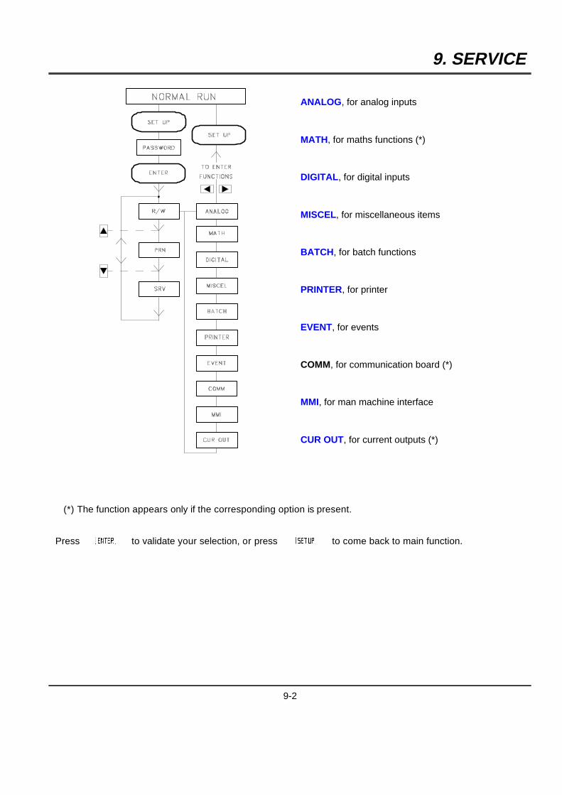
9. SERVICE
ANALOG, for analog inputs
MATH, for maths functions (*)
DIGITAL, for digital inputs
MISCEL, for miscellaneous items
BATCH, for batch functions
PRINTER, for printer
EVENT, for events
COMM, for communication board (*)
MMI, for man machine interface
CUR OUT, for current outputs (*)
(*) The function appears only if the corresponding option is present.
PressAYBto validate your selection, or pressAZBto come back to main function.
9-2

9. SERVICE
9.1.4 ACCESS TO FUNCTIONS DURING SERVICE
TYPES OF SERVICE SELECTION :
The { } keys allows you to select the type of service you want to execute.
The [ ] keys allows you to select the channel on which you want to execute the service.
PressAYBto validate your selection, or pressAZBto come back to main function.
9-3
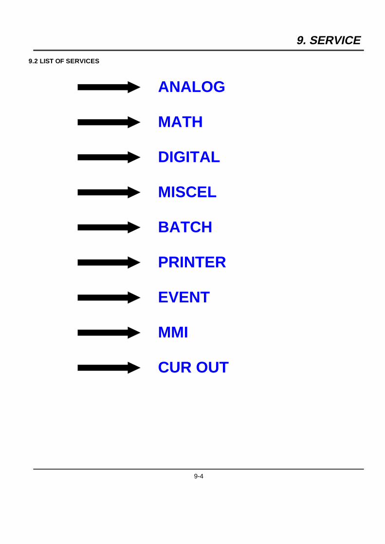
9. SERVICE
9.2 LIST OF SERVICES
ANALOG
MATH
DIGITAL
MISCEL
BATCH
PRINTER
EVENT
MMI
CUR OUT
9-4
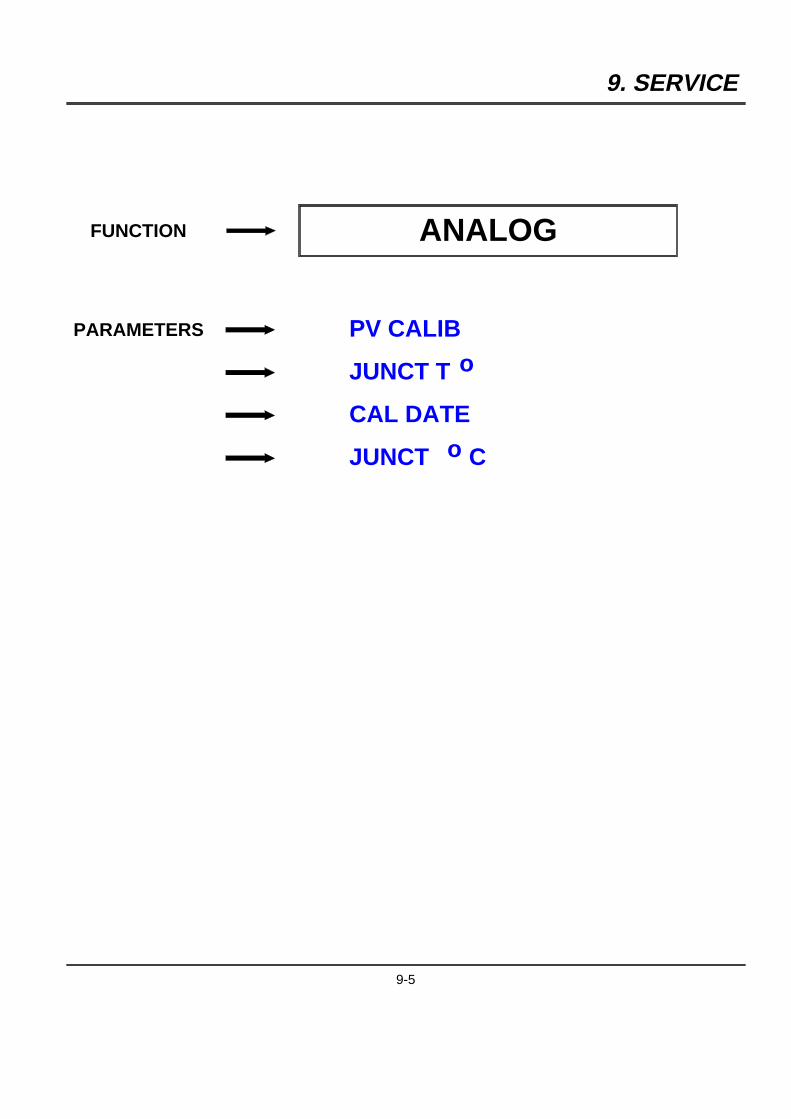
9. SERVICE
FUNCTION ANALOG
PARAMETERS PV CALIB
JUNCT T o
CAL DATE
JUNCT o C
9-5
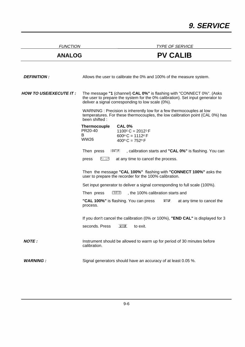
9. SERVICE
FUNCTION TYPE OF SERVICE
ANALOG PV CALIB
DEFINITION : Allows the user to calibrate the 0% and 100% of the measure system.
HOW TO USE/EXECUTE IT : The message "1 (channel) CAL 0%" is flashing with "CONNECT 0%". (Asksthe user to prepare the system for the 0% calibration). Set input generator todeliver a signal corresponding to low scale (0%).
WARNING : Precision is inherently low for a few thermocouples at lowtemperatures. For these thermocouples, the low calibration point (CAL 0%) hasbeen shifted :
ThermocouplePR20-40BWW26
CAL 0%1100oC = 2012oF600oC = 1112oF400oC = 752oF
Then pressAYB, calibration starts and "CAL 0%" is flashing. You can
pressAZBat any time to cancel the process.
Then the message "CAL 100%" flashing with "CONNECT 100%" asks theuser to prepare the recorder for the 100% calibration.
Set input generator to deliver a signal corresponding to full scale (100%).
Then pressAYB, the 100% calibration starts and
"CAL 100%" is flashing. You can pressAZBat any time to cancel theprocess.
If you don't cancel the calibration (0% or 100%), "END CAL" is displayed for 3
seconds. PressAZBto exit.
NOTE : Instrument should be allowed to warm up for period of 30 minutes beforecalibration.
WARNING : Signal generators should have an accuracy of at least 0.05 %.
9-6
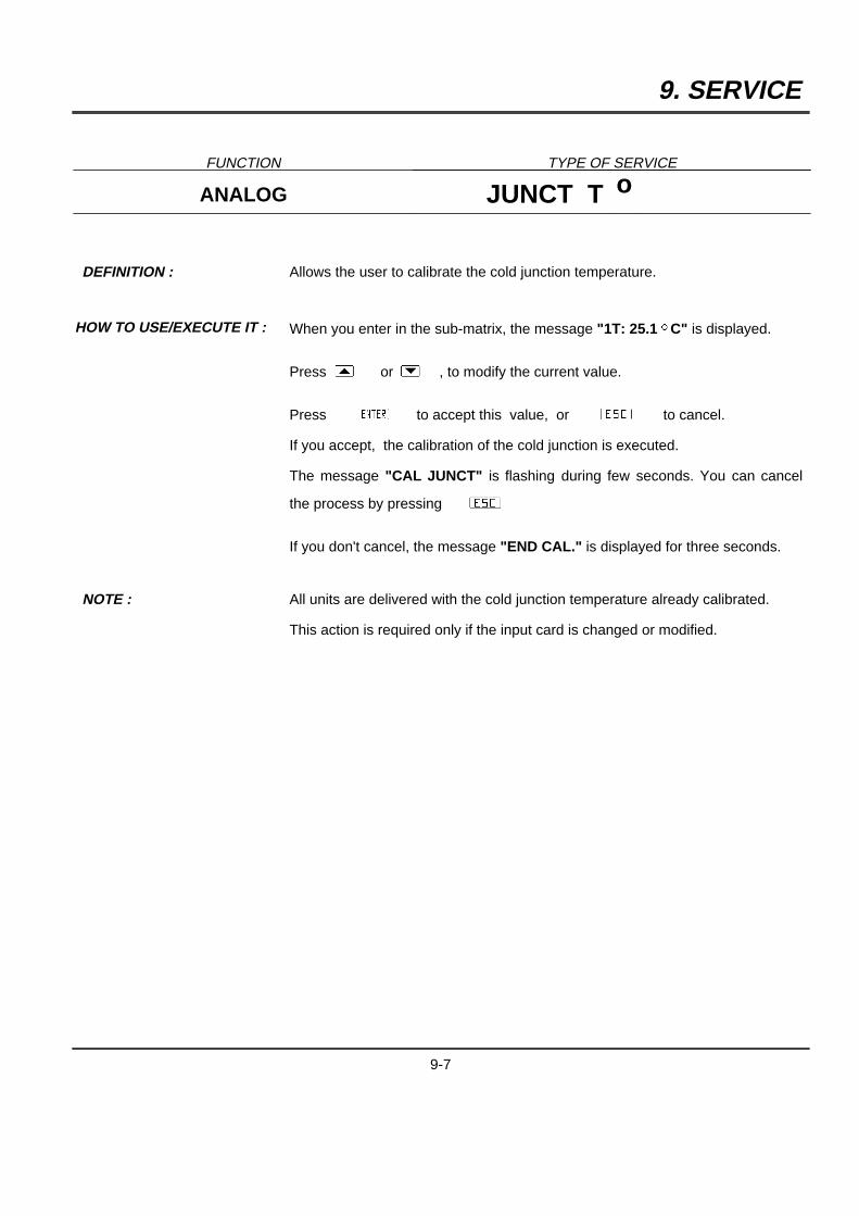
9. SERVICE
FUNCTION TYPE OF SERVICE
ANALOG JUNCT T o
DEFINITION : Allows the user to calibrate the cold junction temperature.
HOW TO USE/EXECUTE IT : When you enter in the sub-matrix, the message "1T: 25.1 oC" is displayed.
Press[ or] , to modify the current value.
Press AYB to accept this value, or ACB to cancel.
If you accept, the calibration of the cold junction is executed.
The message "CAL JUNCT" is flashing during few seconds. You can cancel
the process by pressingACB
If you don't cancel, the message "END CAL." is displayed for three seconds.
NOTE : All units are delivered with the cold junction temperature already calibrated.
This action is required only if the input card is changed or modified.
9-7
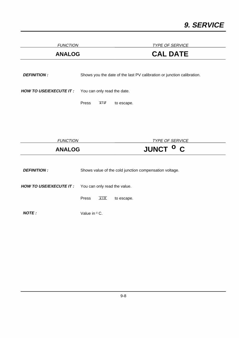
9. SERVICE
FUNCTION TYPE OF SERVICE
ANALOG CAL DATE
DEFINITION : Shows you the date of the last PV calibration or junction calibration.
HOW TO USE/EXECUTE IT : You can only read the date.
PressAZB to escape.
FUNCTION TYPE OF SERVICE
ANALOG JUNCT o C
DEFINITION : Shows value of the cold junction compensation voltage.
HOW TO USE/EXECUTE IT : You can only read the value.
PressAZB to escape.
NOTE : Value in oC.
9-8

9. SERVICE
FUNCTION MATH
PARAMETER TIMER
FUNCTION TYPE OF SERVICE
MATH TIMER
DEFINITION : Displays the current value of timers used for math functions.
HOW TO USE/EXECUTE IT: You can only read the value.
PressAZBto escape.
9-9

9. SERVICE
FUNCTION DIGITAL
PARAMETER STATUS
FUNCTION TYPE OF SERVICE
DIGITAL STATUS
DEFINITION : Displays the status of digital input.
HOW TO USE/EXECUTE IT : You can only read the value.
PressAZB to escape.
9-10
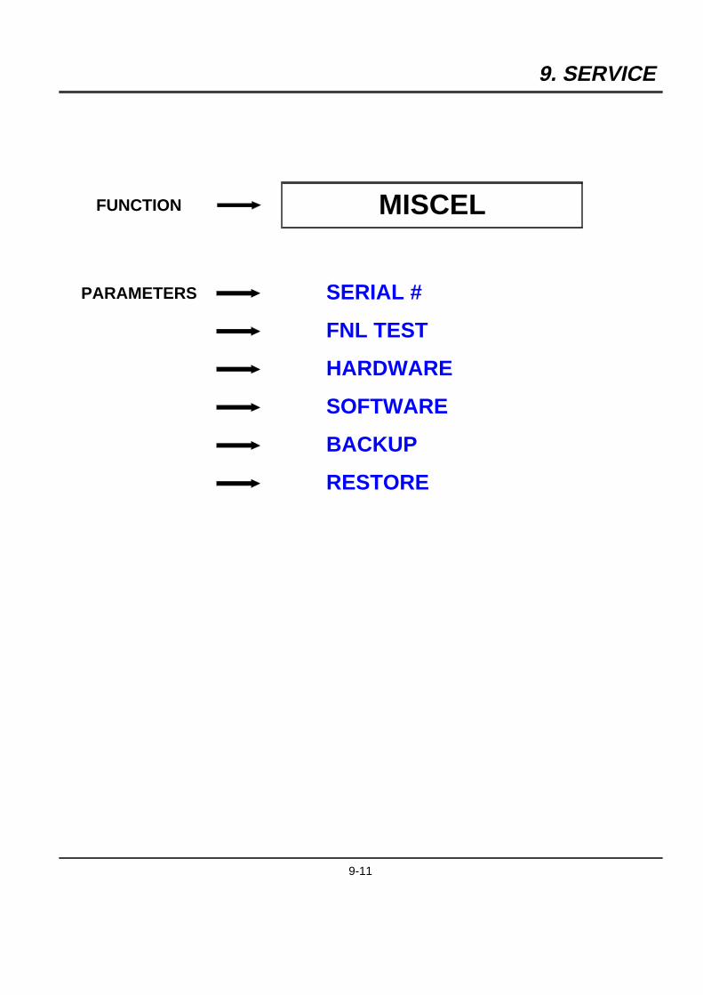
9. SERVICE
FUNCTION MISCEL
PARAMETERS SERIAL #
FNL TEST
HARDWARE
SOFTWARE
BACKUP
RESTORE
9-11
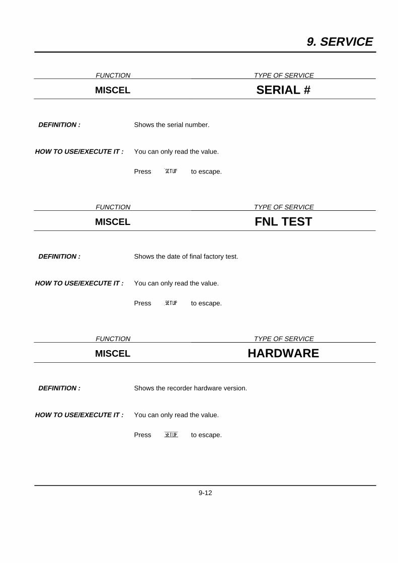
9. SERVICE
FUNCTION TYPE OF SERVICE
MISCEL SERIAL #
DEFINITION : Shows the serial number.
HOW TO USE/EXECUTE IT : You can only read the value.
PressAZB to escape.
FUNCTION TYPE OF SERVICE
MISCEL FNL TEST
DEFINITION : Shows the date of final factory test.
HOW TO USE/EXECUTE IT : You can only read the value.
PressAZB to escape.
FUNCTION TYPE OF SERVICE
MISCEL HARDWARE
DEFINITION : Shows the recorder hardware version.
HOW TO USE/EXECUTE IT : You can only read the value.
PressAZB to escape.
9-12
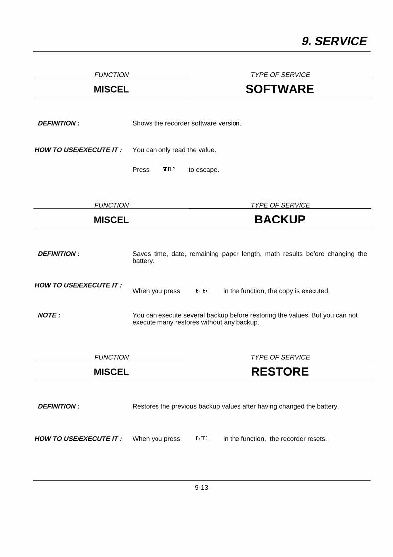
9. SERVICE
FUNCTION TYPE OF SERVICE
MISCEL SOFTWARE
DEFINITION : Shows the recorder software version.
HOW TO USE/EXECUTE IT : You can only read the value.
PressAZB to escape.
FUNCTION TYPE OF SERVICE
MISCEL BACKUP
DEFINITION : Saves time, date, remaining paper length, math results before changing thebattery.
HOW TO USE/EXECUTE IT :When you press AYB in the function, the copy is executed.
NOTE : You can execute several backup before restoring the values. But you can notexecute many restores without any backup.
FUNCTION TYPE OF SERVICE
MISCEL RESTORE
DEFINITION : Restores the previous backup values after having changed the battery.
HOW TO USE/EXECUTE IT : When you press AYB in the function, the recorder resets.
9-13
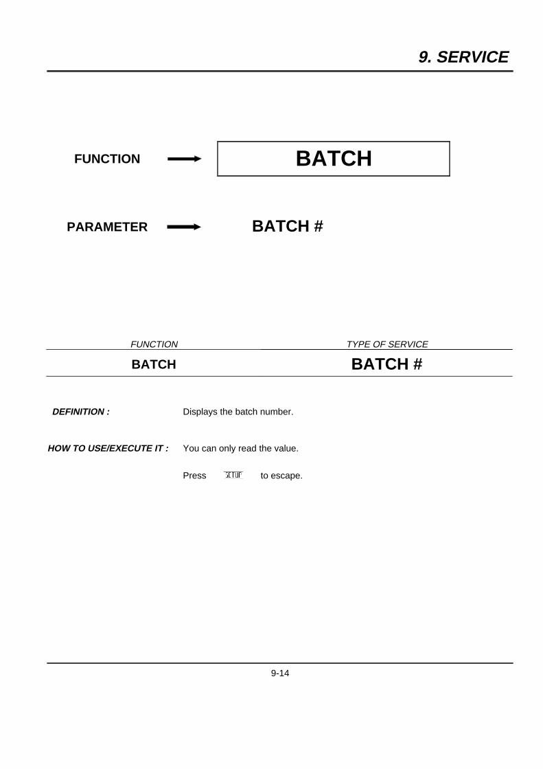
9. SERVICE
FUNCTION BATCH
PARAMETER BATCH #
FUNCTION TYPE OF SERVICE
BATCH BATCH #
DEFINITION : Displays the batch number.
HOW TO USE/EXECUTE IT : You can only read the value.
PressAZB to escape.
9-14
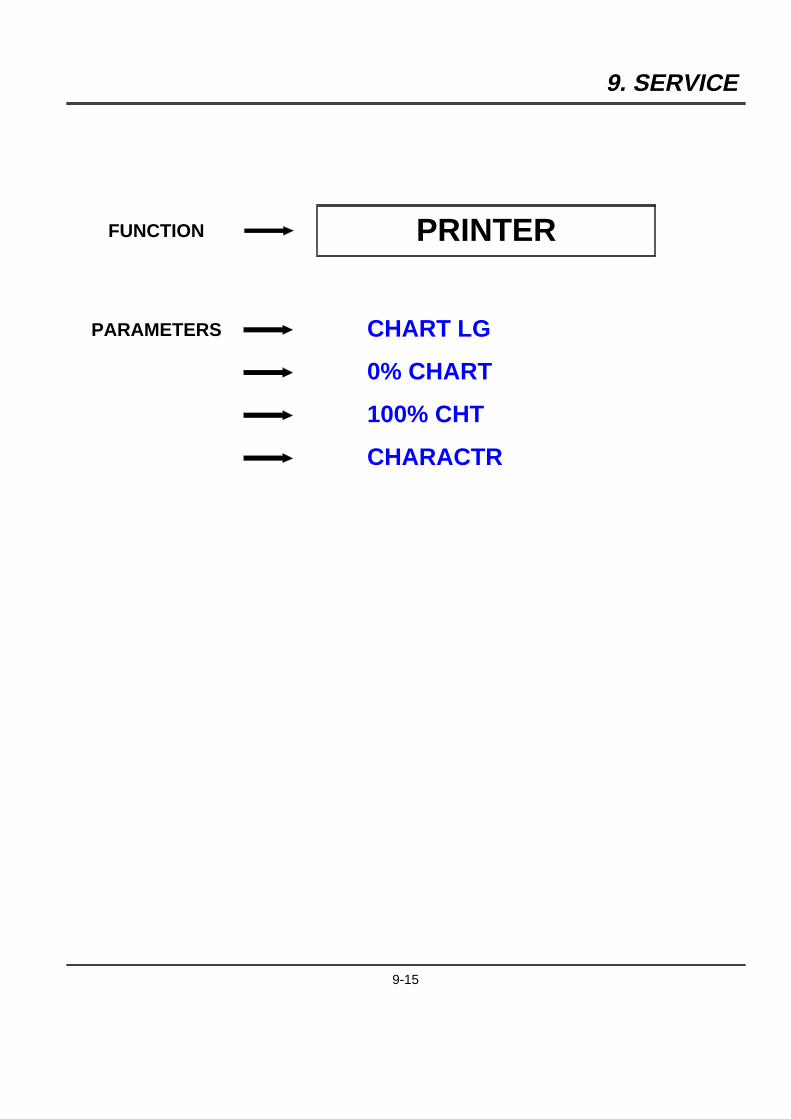
9. SERVICE
FUNCTION PRINTER
PARAMETERS CHART LG
0% CHART
100% CHT
CHARACTR
9-15
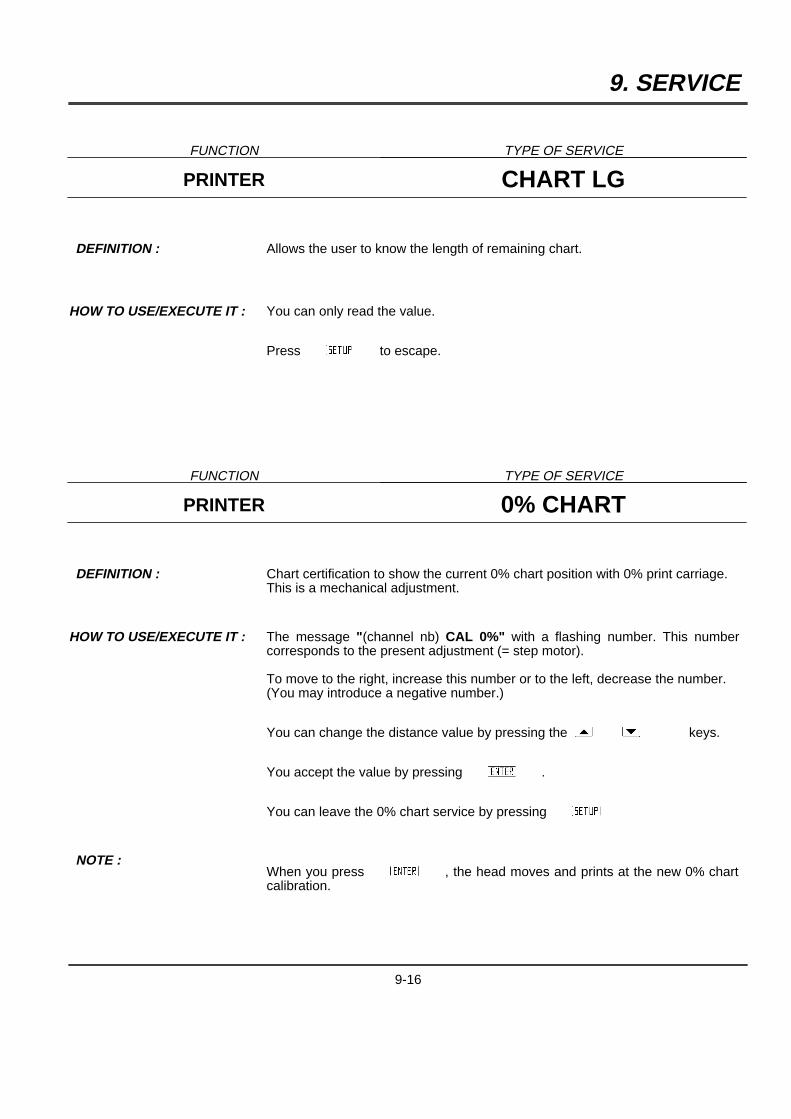
9. SERVICE
FUNCTION TYPE OF SERVICE
PRINTER CHART LG
DEFINITION : Allows the user to know the length of remaining chart.
HOW TO USE/EXECUTE IT : You can only read the value.
PressAZB to escape.
FUNCTION TYPE OF SERVICE
PRINTER 0% CHART
DEFINITION : Chart certification to show the current 0% chart position with 0% print carriage.This is a mechanical adjustment.
HOW TO USE/EXECUTE IT : The message "(channel nb) CAL 0%" with a flashing number. This numbercorresponds to the present adjustment (= step motor).
To move to the right, increase this number or to the left, decrease the number.(You may introduce a negative number.)
You can change the distance value by pressing the[ ] keys.
You accept the value by pressingAYB .
You can leave the 0% chart service by pressingAZB
NOTE :When you pressAYB , the head moves and prints at the new 0% chartcalibration.
9-16

9. SERVICE
FUNCTION TYPE OF SERVICE
PRINTER 100% CHT
DEFINITION : Chart certification to show the current 100% chart position with 100% printcarriage.This is a mechanical adjustment.
HOW TO USE/EXECUTE IT : The message "(channel nb) CAL 100%" with a flashing number. This numbercorresponds to the present adjustment (= step motor).
To move to the right, increase this number or to the left, decrease the number.(You may introduce a negative number.)
You can change the distance value by pressing the[ ] keys.
You accept the value by pressingAYB .
You can leave the 100% chart service by pressingAZB
NOTE :When you pressAYB , the head moves and prints at the new 100%chart calibration.
FUNCTION TYPE OF SERVICE
PRINTER C H A R A C T R
DEFINITION : Prints all the characters available with the printer.
HOW TO USE/EXECUTE IT : The printer test begins when you enter in the function.
You stop it by pressingAZB
NOTE : Lines of 12 characters are printed.
9-17

9. SERVICE
FUNCTION EVENT
PARAMETER EV STATE
FUNCTION TYPE OF SERVICE
EVENT EV STATE
DEFINITION : Shows the event status.
HOW TO USE/EXECUTE IT : You can only read the event status.
PressAZB to escape.
9-18
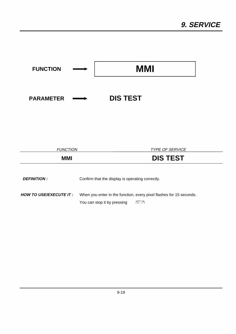
9. SERVICE
FUNCTION MMI
PARAMETER DIS TEST
FUNCTION TYPE OF SERVICE
MMI DIS TEST
DEFINITION : Confirm that the display is operating correctly.
HOW TO USE/EXECUTE IT : When you enter in the function, every pixel flashes for 15 seconds.
You can stop it by pressing AZB
9-19
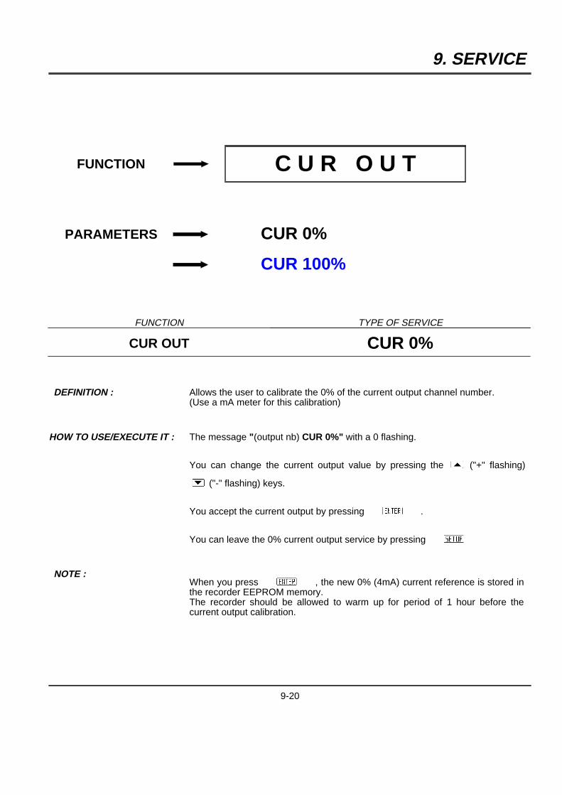
9. SERVICE
FUNCTION C U R O U T
PARAMETERS CUR 0%
CUR 100%
FUNCTION TYPE OF SERVICE
CUR OUT CUR 0%
DEFINITION : Allows the user to calibrate the 0% of the current output channel number.(Use a mA meter for this calibration)
HOW TO USE/EXECUTE IT : The message "(output nb) CUR 0%" with a 0 flashing.
You can change the current output value by pressing the[ ("+" flashing)
] ("-" flashing) keys.
You accept the current output by pressingAYB .
You can leave the 0% current output service by pressingAZB
NOTE :When you pressAYB , the new 0% (4mA) current reference is stored inthe recorder EEPROM memory.The recorder should be allowed to warm up for period of 1 hour before thecurrent output calibration.
9-20
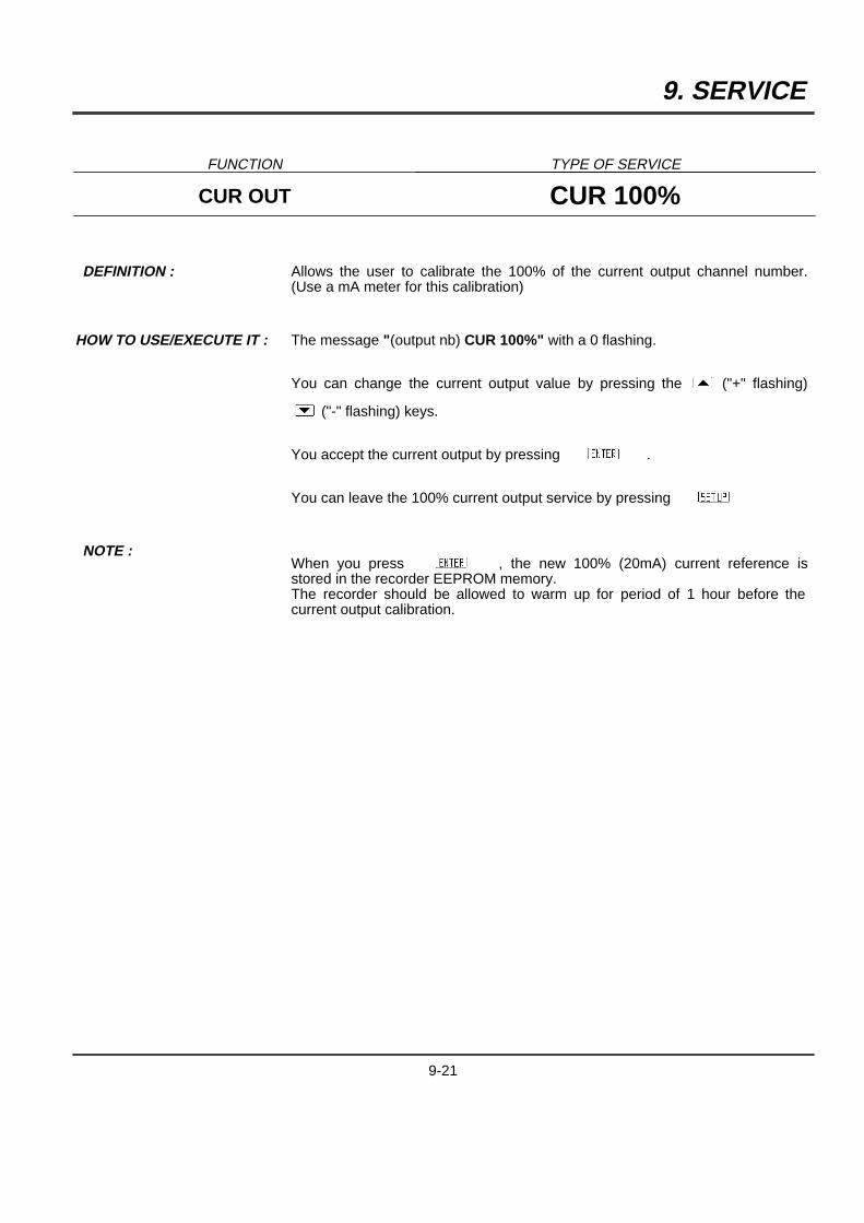
9. SERVICE
FUNCTION TYPE OF SERVICE
CUR OUT CUR 100%
DEFINITION : Allows the user to calibrate the 100% of the current output channel number.(Use a mA meter for this calibration)
HOW TO USE/EXECUTE IT : The message "(output nb) CUR 100%" with a 0 flashing.
You can change the current output value by pressing the[ ("+" flashing)
] ("-" flashing) keys.
You accept the current output by pressingAYB .
You can leave the 100% current output service by pressingAZB
NOTE :When you press AYB , the new 100% (20mA) current reference isstored in the recorder EEPROM memory.The recorder should be allowed to warm up for period of 1 hour before thecurrent output calibration.
9-21

9. SERVICE
9-22

10. PC LOADER
10.1 OVERVIEW
You have just received your application software package. This tool has been designed to modify,upload/download and store the recorder configuration.
10.2 REQUIRED MATERIAL
A PC AT compatible personal computer with :
5 a serial Communication card : RS232
5 a hard disk
5 a color or B/W monitor (EGA, VGA, Hercules or CGA)
5 A mouse is optional.
5 Up to 625 Kbytes RAM free.
Please order the RS232/CMOS adaptor.
10.3 PRODUCT FEATURES
The main functions of this software are :
5 Reading the configuration of your recorder.
5 Preparing or modifying the configuration from your PC.
5 Downloading configuration from your PC to the recorder.
5 Retrieving configuration stored on hard disk.
5 Saving configuration on hard disk.
5 Making diagnostics.
5 Upgrading software version.
5 Creating special customer actuations.
5 Monitoring data.
10-1

10. PC LOADER
10.4 INSTALLATION
10.4.1 Copying your master floppy disk
Before using your application software package, we recommend you first make a backup copy of the masterfloppy disk.
5 Insert the master floppy disk in the A drive of your PC.
5 TypeA:
and press AYB
5 TypeDISKCOPY
and press AYB
5 Then follow the PC screen instructions.
5 Protect the master floppy disk from dust, magnetic fields and high temperatures. Use the copy of the masterfloppy disk for routine operations.
10.4.2 Installing the software on the hard disk
5 Insert the copy of the master floppy disk in the A drive of your PC.
5 TypeA:
and press AYB
5 TypeINSTALL
and press AYB
5 Installation is then automatic.
10-2

10. PC LOADER
10.4.3 Use
10.4.3.1 Operating the application software
5 TypeC:
and press AYB
5 TypeCD PCLOADER
and press AYB
5 TypeGO
and press AYB
5 After few seconds, the software program will ask for the access code. Enter your password and confirm by
pressingAYB
10.4.3.2 Using the keyboard or the mouse
10.4.3.2.1 Menus
The software is based on the use of menu bars. To confirm a menu, you have three methods :
5 Placing the cursor on the chosen menu, then press AYB
5 Pressing the highlighted key letter of the menu's name.
5 Using the mouse.
10.4.3.2.2 Modifying fields of parameters
Some menus may allow the modification of parameter's values. There are two kinds of modifications accordingto the type of parameters.
5 Selective modification : When placing the index on the chosen parameter, you can modify it by pressing
the [ or ] keys to scroll through allowed values. Most modifications are of this type.
5 Modifying with the alphanumeric keyboard : in this case, position the cursor on the chosen parameter and typethe required value.
10-3

10. PC LOADER
10.4.3.2.3 Going from a parameter field to another one
5 Press } orAYB to access to the next field.
5 Press { to access to the previous field.
Each time the cursor points to a field, a "help" message is displayed on the bottom line of the screen.
10.4.3.2.4 Leaving a menu
To leave a menu, you have two options :
5 To leave the present menu and save your modifications,
press ADBkey.
5 To leave the present menu without saving modifications,
press ACBkey.
10.5 SET UP COMM
In case you choose to use the communication option instead of the jack, you have to define the address of therecorder. (configured in the COMM sub-matrix)
Then you have to configure "NO CALL" in the AUTODIAL parameter of the recorder (COMM) and to configure"NEVER" in the FRQUNCY parameter (REPORT).
10-4

10. PC LOADER
10.6 CONFIGURATION
10.6.1 Read and modify
Allows to read and modify a configuration.
10.6.2 User actuation
Allows the user to create his own specific sensor/range array, to load/save it, to download/upload it.
Up to 2 user actuations can be downloaded into the same recorder.
10.6.2.1 Definition of a user actuation
Select "READ AND MODIFY USER ACTUATION", define the user actuation number and give a file name tosave the user actuation.
10.6.2.2 Select the type of sensor
If T/C is chosen, you have to define the ambient temperature and the corresponding voltage at the rear of therecorder, for cold junction compensation.Then define up to 51 dots, less if you want.
Then pressAFBto sort your dots.
If it is OK, press ADB to save your definition.
10-5
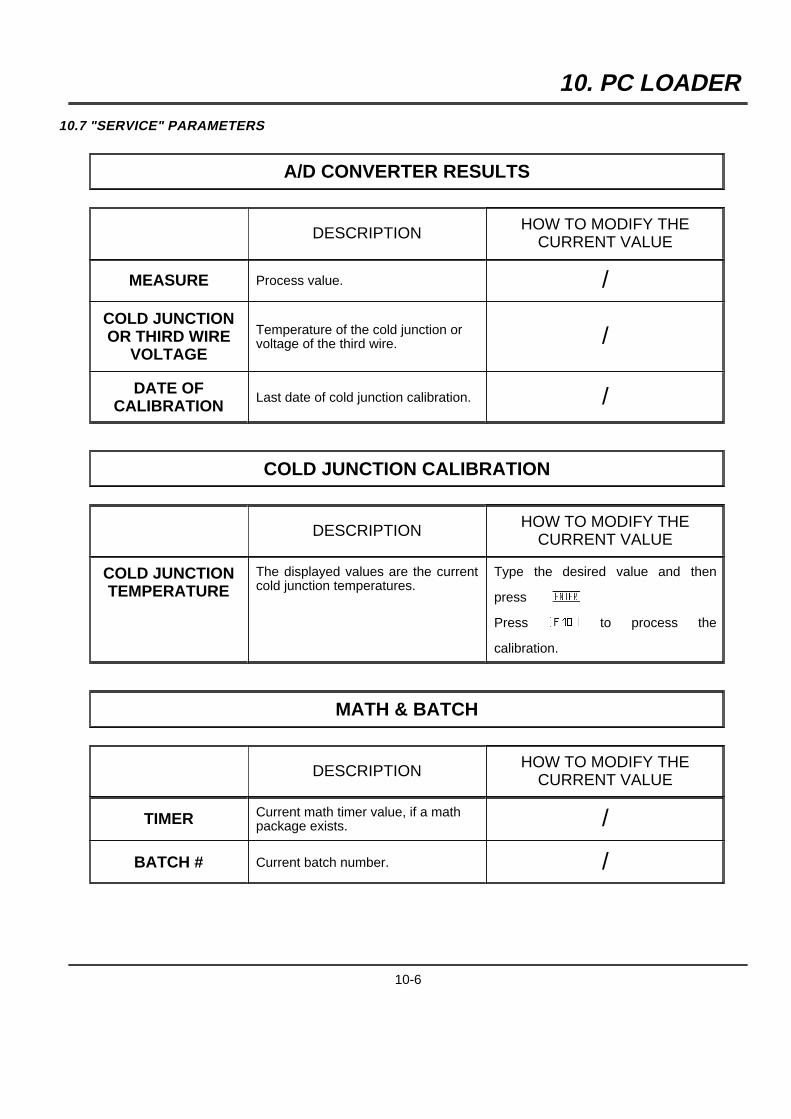
10. PC LOADER
10.7 "SERVICE" PARAMETERS
A/D CONVERTER RESULTS
DESCRIPTION HOW TO MODIFY THECURRENT VALUE
MEASURE Process value. /
COLD JUNCTIONOR THIRD WIRE
VOLTAGE
Temperature of the cold junction orvoltage of the third wire. /
DATE OFCALIBRATION
Last date of cold junction calibration. /
COLD JUNCTION CALIBRATION
DESCRIPTION HOW TO MODIFY THECURRENT VALUE
COLD JUNCTIONTEMPERATURE
The displayed values are the currentcold junction temperatures.
Type the desired value and then
pressAYBPressADBto process the
calibration.
MATH & BATCH
DESCRIPTION HOW TO MODIFY THECURRENT VALUE
TIMER Current math timer value, if a mathpackage exists. /
BATCH # Current batch number. /
10-6
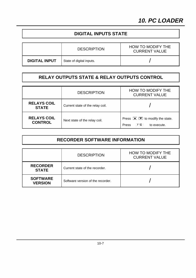
10. PC LOADER
DIGITAL INPUTS STATE
DESCRIPTION HOW TO MODIFY THECURRENT VALUE
DIGITAL INPUT State of digital inputs. /
RELAY OUTPUTS STATE & RELAY OUTPUTS CONTROL
DESCRIPTION HOW TO MODIFY THECURRENT VALUE
RELAYS COILSTATE
Current state of the relay coil. /
RELAYS COILCONTROL
Next state of the relay coil. Press[] to modify the state.
PressADB to execute.
RECORDER SOFTWARE INFORMATION
DESCRIPTION HOW TO MODIFY THECURRENT VALUE
RECORDERSTATE
Current state of the recorder. /
SOFTWAREVERSION
Software version of the recorder. /
10-7
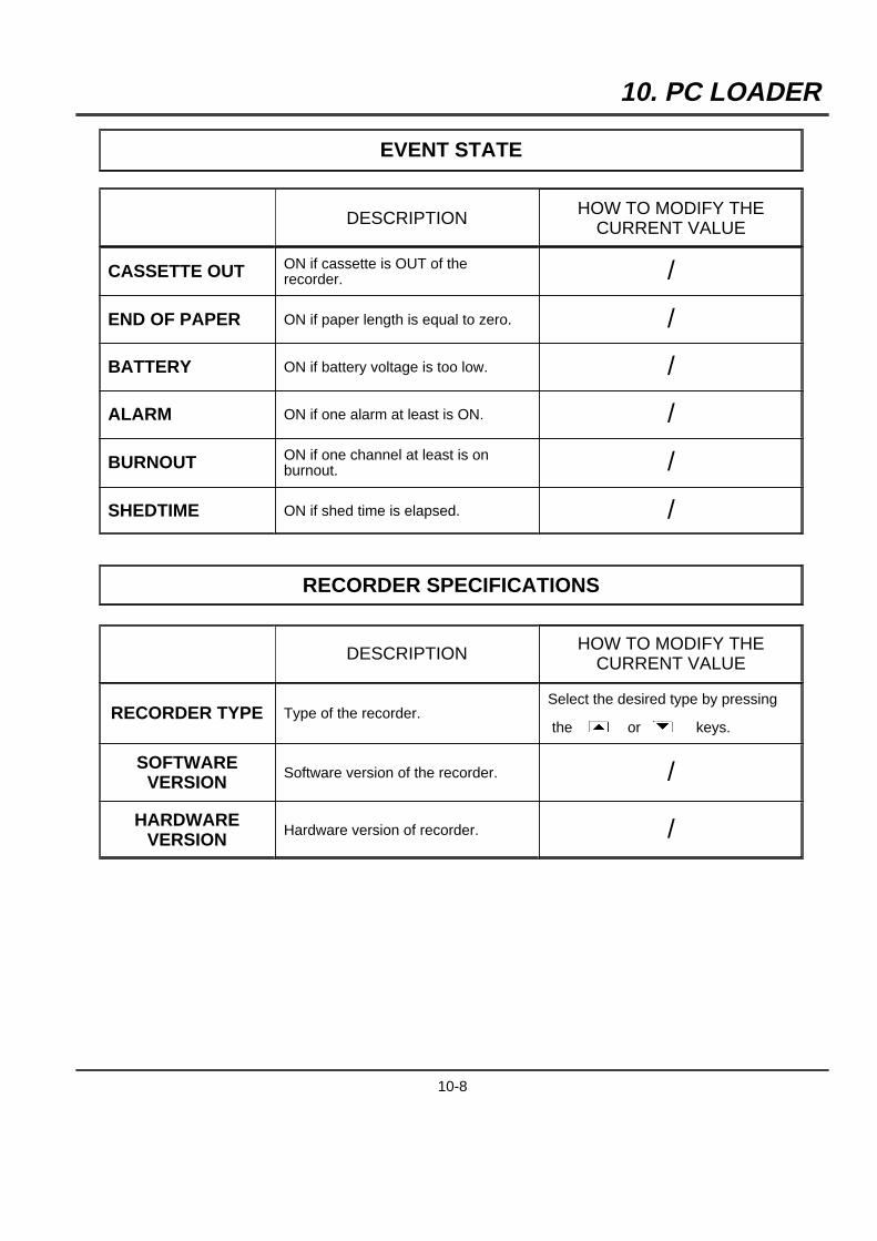
10. PC LOADER
EVENT STATE
DESCRIPTION HOW TO MODIFY THECURRENT VALUE
CASSETTE OUT ON if cassette is OUT of therecorder. /
END OF PAPER ON if paper length is equal to zero. /
BATTERY ON if battery voltage is too low. /
ALARM ON if one alarm at least is ON. /
BURNOUT ON if one channel at least is onburnout. /
SHEDTIME ON if shed time is elapsed. /
RECORDER SPECIFICATIONS
DESCRIPTION HOW TO MODIFY THECURRENT VALUE
RECORDER TYPE Type of the recorder.Select the desired type by pressing
the [ or ] keys.
SOFTWAREVERSION
Software version of the recorder. /
HARDWAREVERSION
Hardware version of recorder. /
10-8

10. PC LOADER
MODIFY DATE & TIME ON RECORDER
DESCRIPTION HOW TO MODIFY THECURRENT VALUE
DATE Current date of the recorder Type the desired value and then
pressAYBTIME Current time of the recorder
10.8 MONITORING
10.8.1 PARAMETERS INITIALIZATION
MAIN allows you to define :
- the sample period of the monitoring or archiving.
- a list of recorders you want to monitor/apply archiving and
for monitoring : SAMPLING RATE must be active
for archiving : SAMPLING RATE and ARCHIVING STATE must be active
ARCHIVING allows you to define the quantity and the size of the archived files.
10.8.2 REAL TIME DISPLAY
You are allowed to select the type of monitoring screen.
When using the [ or ] keys, you can change the recorder to monitor.
10.8.3 START/STOP ARCHIVING
To start or to stop archiving.
Archived files are stored in C:\PC LOADER\PC100CD\MONITOR directory.
10-9

10. PC LOADER
The name of the ASCII files is "ASC XX - YY.EEE" where
5 ASC stands for "ASCII"
5 XX is the address of the recorder (01-99) or 00 when communication is made through JACK.
5 YY is the file group number (00-09)
5 EEE is the type of information contained in the file :
ANL stands for "analog input values and digital input status"MAT stands for "mathematical function results"AL1 stands for "alarm status and event status"AL2 stands for "time of occurrence of alarms"CFG stands for "configuration"
10.9 UPDATE SOFTWARE (FOR JACK ONLY)
Insert the floppy that contains the "updated" recorder program in the drive.To speed up the update, you can copy the entire floppy on hard disk (where you want).Then execute PCLOADER ("GO") and select the "UPDATE SOFTWARE" menu.Follow the instructions displayed on the screen.Be sure you have connected the recorder to the PC before any download of code.The update takes around 10 minutes.
Do not switch off the recorder after an update.
10-10

11. TROUBLESHOOTING
11.1 FAILURE SYMPTOMS AND TROUBLESHOOTING PROCEDURES
9 Compare the symptoms with those listed below to identify the possible cause and take the corrective action.9 If the recorder is not restored to normal condition by the following check, please contact your nearest service
office.9 CAUTION : Ensure power disconnected before removing any boards from the recorder. Avoid touching
components unless you are protected against electrostatic discharge as many boards have CMOScomponents which may be damaged.
11.2 TROUBLESHOOTING LIST
Before any operation, for mechanical trouble execute an auto-test control. (For complete information seeCK 114)
11.2.1 SELF-TEST MODE PEN RECORDER
9 To access self-test mode, press theAZBkey when powering up.9 The self-test involves the DIAGNOSTIC and the RUNNING IN.9 As soon as the self-test begins, the DIAGNOSTIC starts and the RUNNING IN follows automatically.
(See fig. 11-2)
1 DIAGNOSTIC :9 Duration : 5 mn approximately,9 To show the quality of mechanical adjustments and motor torque margins,9 To be significant, this operation has to be made in normal conditions :
20 0C +/-50C, 60 % RH +/-15 %, mounted horizontally with new pen cartridge(s).
2 RUNNING IN :9 Duration : 2 hours,9 Mechanical burn-in.
NOTE : - The cassette detection is made only at the beginning of the diagnostic.- The self-test is made with the recorder cassette with a 3 m minimum length of chart.
11.2.1.1 Diagnostic pen recorder
11.2.1.1.1 Control of the pen 1 adjustment
9 The figure 11-2 ref. 1 shows the check-test for the height pen 1 adjustment.9 The scale extends from 1 to 9, a correct adjustment is between 4 and 9.
11-1
11. TROUBLESHOOTING
11.2.1.1.2 Mechanical limits
9 The figure 11-2 ref. 2 shows the test of mechanical extremes.The vertical line(s) on the right must be over the 100 % chart.The vertical line(s) on the left must be under the 0 % chart.
11.2.1.1.3 Printing of the mechanical 0 % and 100 %
9 The figure 11-2 ref. 3 shows the adjustment of the recorder. If the recorder is calibrated, the vertical linesmust be written at the same place as the 0 % and the 100 % chart.
11.2.1.1.4 Chart advance and print test
9 The figure 11-2 ref. 4 shows the test for chart advance with a diagram written every 20 mm.
11.2.1.1.5 Printing of information message
9 The figure 11-2 ref. 5 shows the message.9 Time and date,9 Software version,9 Chart identification number
11.2.1.1.6 Test for motor torque margins and mechanical slacks
9 The figure 11-2 ref. 6 is composed of 3 identical patterns for the pens 2 and 3 and the graph for pen 1 isdiscontinuous on the two first patterns.
9 The first pattern for each channel is executed in subvoltage condition and the movements are accelerated.
11.2.1.1.7 Adjustment check
9 For each channel, an adjustment check is executed at the end of the diagnostic. See figure 11-1 ref. 7.
11.2.1.2 Running in pen recorder (See fig. 11-1)
9 For 2 hours9 Consumption : 3 m of chart paper9 The recorder prints a message every 65 mm, indicating the number of remaining cycles.
(Total 36 cycles)9 For each cycle, the carriage adjustment check result is the following:
on the left channel one, on the middle channel two and on the right channel three.For each channel: on the right the set value (22 or 23) and on the left the relative error (error values between-3 and +3 included are correct).
9 At the end, the recorder executes a new DIAGNOSTIC, then indicates an end message with recapitulation ofdefective adjustment check.
11-2
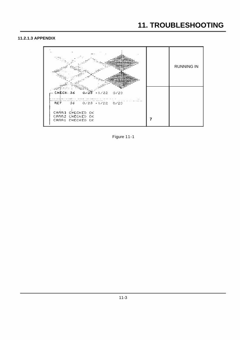
11. TROUBLESHOOTING
11.2.1.3 APPENDIX
RUNNING IN
7
Figure 11-1
11-3
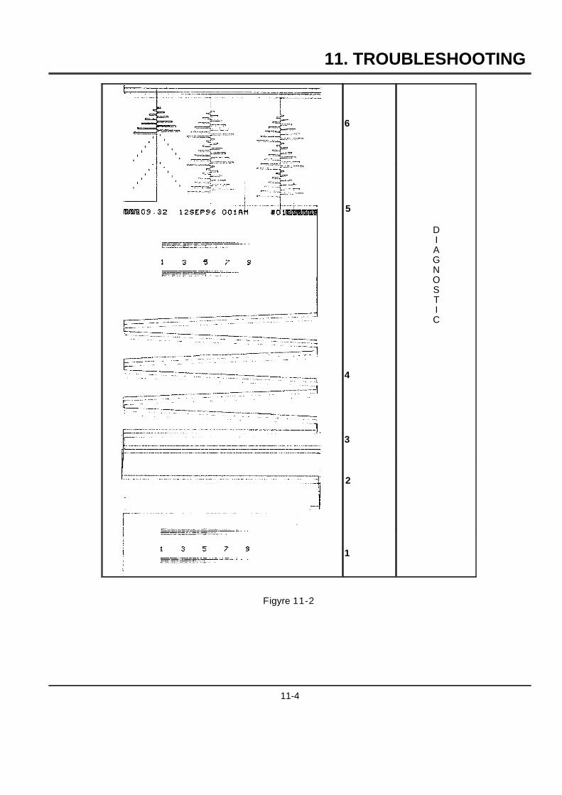
11. TROUBLESHOOTING
6
DIAGNOSTIC
5
4
3
2
1
Figyre 11-2
11-4
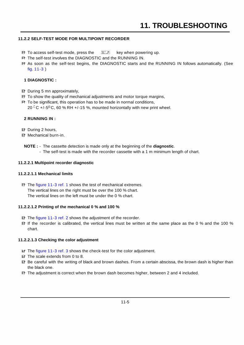
11. TROUBLESHOOTING
11.2.2 SELF-TEST MODE FOR MULTIPOINT RECORDER
9 To access self-test mode, press theAZBkey when powering up.9 The self-test involves the DIAGNOSTIC and the RUNNING IN.9 As soon as the self-test begins, the DIAGNOSTIC starts and the RUNNING IN follows automatically. (See
fig. 11-3 )
1 DIAGNOSTIC :
9 During 5 mn approximately,9 To show the quality of mechanical adjustments and motor torque margins,9 To be significant, this operation has to be made in normal conditions,
20 0C +/-50C, 60 % RH +/-15 %, mounted horizontally with new print wheel.
2 RUNNING IN :
9 During 2 hours,9 Mechanical burn-in.
NOTE : - The cassette detection is made only at the beginning of the diagnostic.- The self-test is made with the recorder cassette with a 1 m minimum length of chart.
11.2.2.1 Multipoint recorder diagnostic
11.2.2.1.1 Mechanical limits
9 The figure 11-3 ref. 1 shows the test of mechanical extremes.The vertical lines on the right must be over the 100 % chart.The vertical lines on the left must be under the 0 % chart.
11.2.2.1.2 Printing of the mechanical 0 % and 100 %
9 The figure 11-3 ref. 2 shows the adjustment of the recorder.9 If the recorder is calibrated, the vertical lines must be written at the same place as the 0 % and the 100 %
chart.
11.2.2.1.3 Checking the color adjustment
9 The figure 11-3 ref. 3 shows the check-test for the color adjustment.9 The scale extends from 0 to 8.9 Be careful with the writing of black and brown dashes. From a certain abscissa, the brown dash is higher than
the black one.9 The adjustment is correct when the brown dash becomes higher, between 2 and 4 included.
11-5
11. TROUBLESHOOTING
11.2.2.1.4 Printing of information message
9 The figure 11-3 ref. 4 shows the message.9 Time and date,9 Software version,9 Chart identification number.
11.2.2.1.5 Checking the answer of the pen tip
9 The figure 11-3 ref. 5 shows the printing test.9 See 2 horizontal lines written in 6 colors.
11.2.2.1.6 Test for motor torque margins and mechanical slacks
9 The figure 11-3 ref. 6 is composed of 3 serrated parts and each of them cut with a black line in the middle.9 The first serrated part and the beginning of the black line are executed with subvoltage, and movements are
accelerated. (Coil included)
11.2.2.1.7 Chart advance and print test
9 The figure 11-3 ref. 6 shows the test for chart advance with a diagram written every 20 mm.
11.2.2.1.8 Adjustment check
9 An adjustment check for carriage and colors is executed at the end of the diagnostic.9 For the carriage:
on the right the set value (22 or 23) and on the left the relative error (error values between -3 and +3 includedare correct).
9 For the color:on the right the set value (20 or 21) and on the left the relative error (error values between -3 and +3 includedare correct).
11.2.2.2 Running in multipoint recorder
9 For 2 hours9 Consumption : 1 m of chart paper9 The recorder prints a message every cycle, indicating the number of remaining cycles,
(22 cycles at all),9 The 2 different graphs are the following (See figure 11-3 ref 7 and 8)9 For each cycle, the adjustment is controlled for carriage and colors.
The adjustment check result is the following: on the left the carriage control and on the right the color control.9 At the end, the recorder executes a new DIAGNOSTIC, then indicates an end message with recapitulation of
defective adjustment check .
11-6
11. TROUBLESHOOTING
11.2.2.3 APPENDIX
8
RUNNING
IN
7
6
54
3
21
DIAGNOSTIC
Figure 11-3
11-7
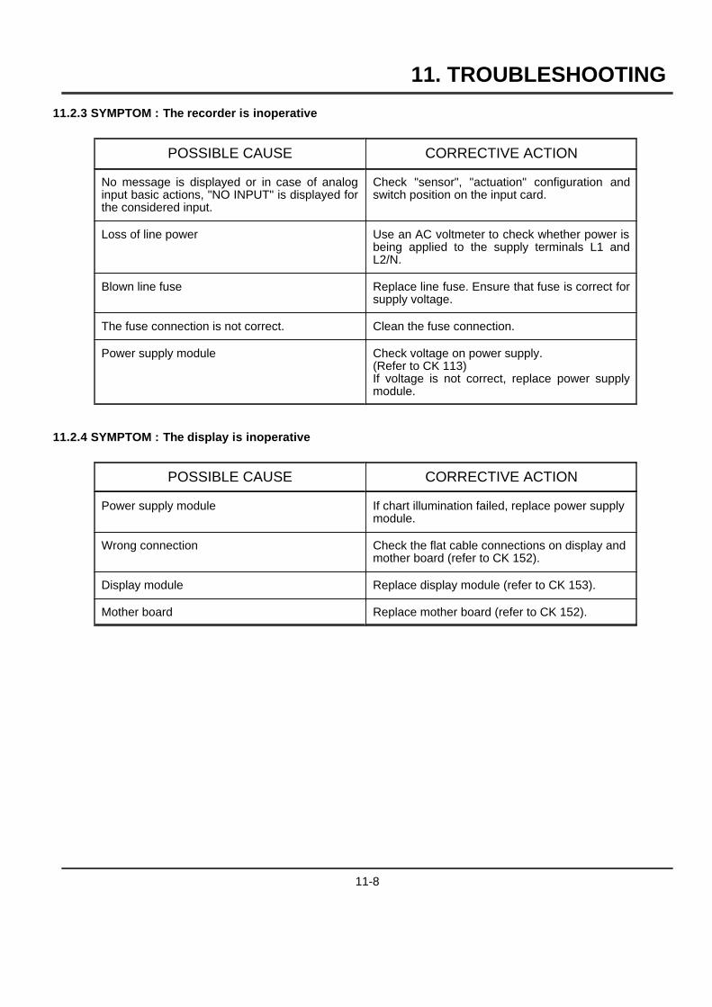
11. TROUBLESHOOTING
11.2.3 SYMPTOM : The recorder is inoperative
POSSIBLE CAUSE CORRECTIVE ACTION
No message is displayed or in case of analoginput basic actions, "NO INPUT" is displayed forthe considered input.
Check "sensor", "actuation" configuration andswitch position on the input card.
Loss of line power Use an AC voltmeter to check whether power isbeing applied to the supply terminals L1 andL2/N.
Blown line fuse Replace line fuse. Ensure that fuse is correct forsupply voltage.
The fuse connection is not correct. Clean the fuse connection.
Power supply module Check voltage on power supply.(Refer to CK 113)If voltage is not correct, replace power supplymodule.
11.2.4 SYMPTOM : The display is inoperative
POSSIBLE CAUSE CORRECTIVE ACTION
Power supply module If chart illumination failed, replace power supplymodule.
Wrong connection Check the flat cable connections on display andmother board (refer to CK 152).
Display module Replace display module (refer to CK 153).
Mother board Replace mother board (refer to CK 152).
11-8
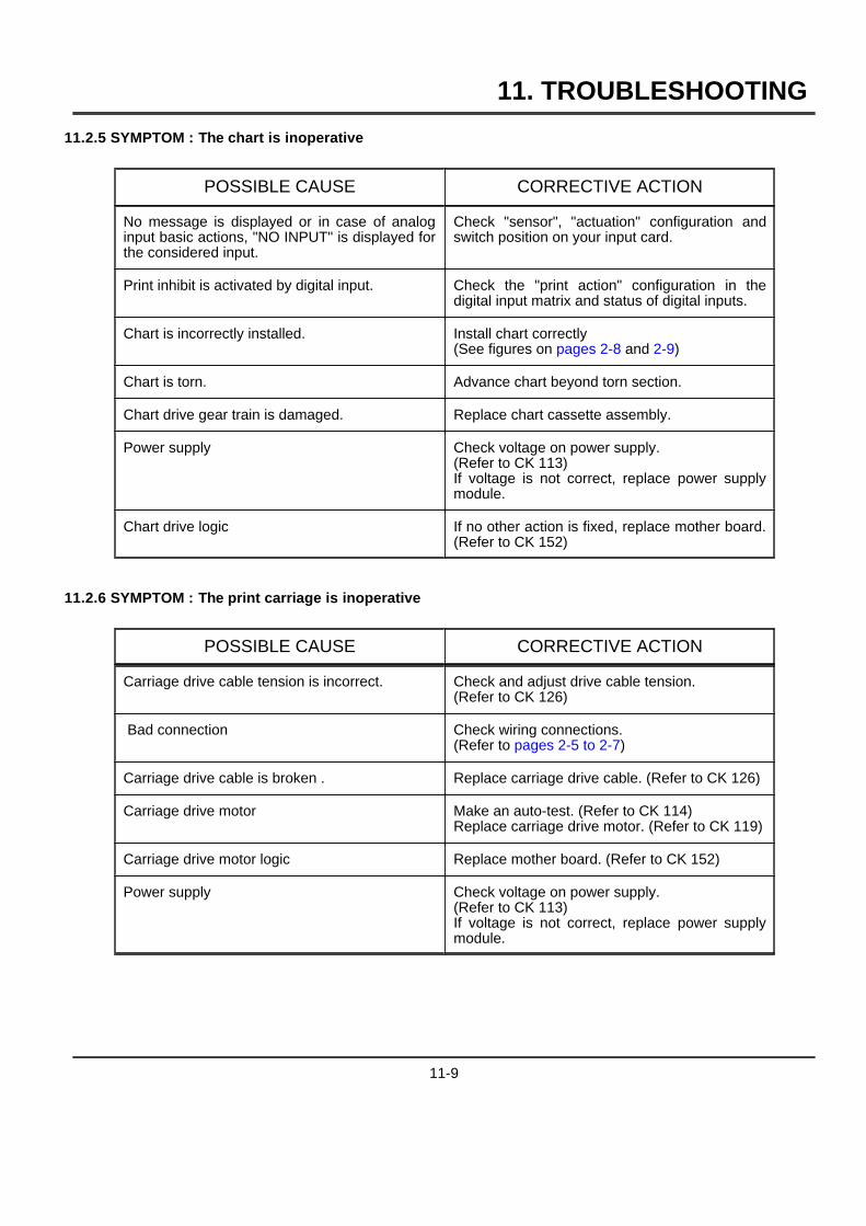
11. TROUBLESHOOTING
11.2.5 SYMPTOM : The chart is inoperative
POSSIBLE CAUSE CORRECTIVE ACTION
No message is displayed or in case of analoginput basic actions, "NO INPUT" is displayed forthe considered input.
Check "sensor", "actuation" configuration andswitch position on your input card.
Print inhibit is activated by digital input. Check the "print action" configuration in thedigital input matrix and status of digital inputs.
Chart is incorrectly installed. Install chart correctly(See figures on pages 2-8 and 2-9)
Chart is torn. Advance chart beyond torn section.
Chart drive gear train is damaged. Replace chart cassette assembly.
Power supply Check voltage on power supply.(Refer to CK 113)If voltage is not correct, replace power supplymodule.
Chart drive logic If no other action is fixed, replace mother board.(Refer to CK 152)
11.2.6 SYMPTOM : The print carriage is inoperative
POSSIBLE CAUSE CORRECTIVE ACTION
Carriage drive cable tension is incorrect. Check and adjust drive cable tension.(Refer to CK 126)
Bad connection Check wiring connections.(Refer to pages 2-5 to 2-7)
Carriage drive cable is broken . Replace carriage drive cable. (Refer to CK 126)
Carriage drive motor Make an auto-test. (Refer to CK 114)Replace carriage drive motor. (Refer to CK 119)
Carriage drive motor logic Replace mother board. (Refer to CK 152)
Power supply Check voltage on power supply.(Refer to CK 113)If voltage is not correct, replace power supplymodule.
11-9
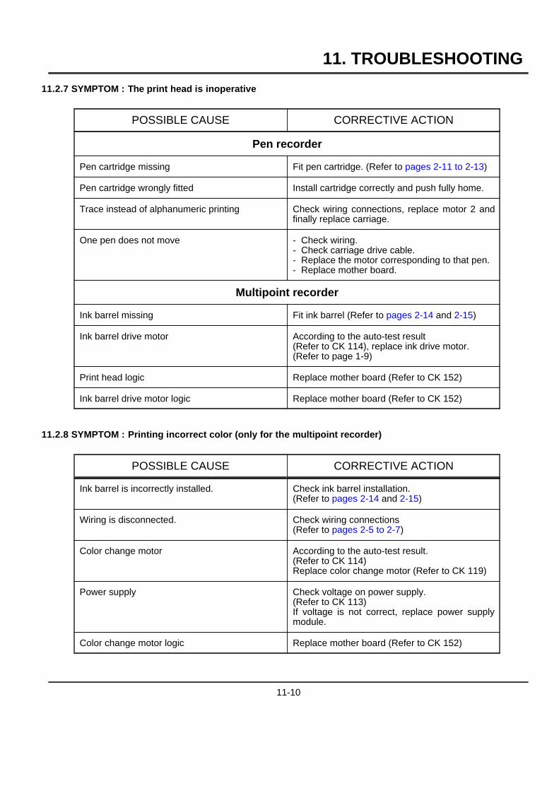
11. TROUBLESHOOTING
11.2.7 SYMPTOM : The print head is inoperative
POSSIBLE CAUSE CORRECTIVE ACTION
Pen recorder
Pen cartridge missing Fit pen cartridge. (Refer to pages 2-11 to 2-13)
Pen cartridge wrongly fitted Install cartridge correctly and push fully home.
Trace instead of alphanumeric printing Check wiring connections, replace motor 2 andfinally replace carriage.
One pen does not move - Check wiring.- Check carriage drive cable.- Replace the motor corresponding to that pen.- Replace mother board.
Multipoint recorder
Ink barrel missing Fit ink barrel (Refer to pages 2-14 and 2-15)
Ink barrel drive motor According to the auto-test result(Refer to CK 114), replace ink drive motor.(Refer to page 1-9)
Print head logic Replace mother board (Refer to CK 152)
Ink barrel drive motor logic Replace mother board (Refer to CK 152)
11.2.8 SYMPTOM : Printing incorrect color (only for the multipoint recorder)
POSSIBLE CAUSE CORRECTIVE ACTION
Ink barrel is incorrectly installed. Check ink barrel installation.(Refer to pages 2-14 and 2-15)
Wiring is disconnected. Check wiring connections(Refer to pages 2-5 to 2-7)
Color change motor According to the auto-test result.(Refer to CK 114)Replace color change motor (Refer to CK 119)
Power supply Check voltage on power supply.(Refer to CK 113)If voltage is not correct, replace power supplymodule.
Color change motor logic Replace mother board (Refer to CK 152)
11-10
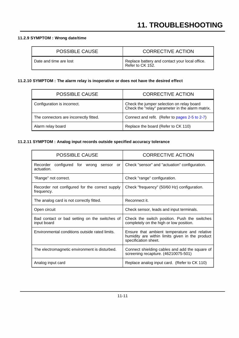
11. TROUBLESHOOTING
11.2.9 SYMPTOM : Wrong date/time
POSSIBLE CAUSE CORRECTIVE ACTION
Date and time are lost Replace battery and contact your local office.Refer to CK 152.
11.2.10 SYMPTOM : The alarm relay is inoperative or does not have the desired effect
POSSIBLE CAUSE CORRECTIVE ACTION
Configuration is incorrect. Check the jumper selection on relay boardCheck the "relay" parameter in the alarm matrix.
The connectors are incorrectly fitted. Connect and refit. (Refer to pages 2-5 to 2-7)
Alarm relay board Replace the board (Refer to CK 110)
11.2.11 SYMPTOM : Analog input records outside specified accuracy tolerance
POSSIBLE CAUSE CORRECTIVE ACTION
Recorder configured for wrong sensor oractuation.
Check "sensor" and "actuation" configuration.
"Range" not correct. Check "range" configuration.
Recorder not configured for the correct supplyfrequency.
Check "frequency" (50/60 Hz) configuration.
The analog card is not correctly fitted. Reconnect it.
Open circuit Check sensor, leads and input terminals.
Bad contact or bad setting on the switches ofinput board
Check the switch position. Push the switchescompletely on the high or low position.
Environmental conditions outside rated limits. Ensure that ambient temperature and relativehumidity are within limits given in the productspecification sheet.
The electromagnetic environment is disturbed. Connect shielding cables and add the square ofscreening recapture. (46210075-501)
Analog input card Replace analog input card. (Refer to CK 110)
11-11
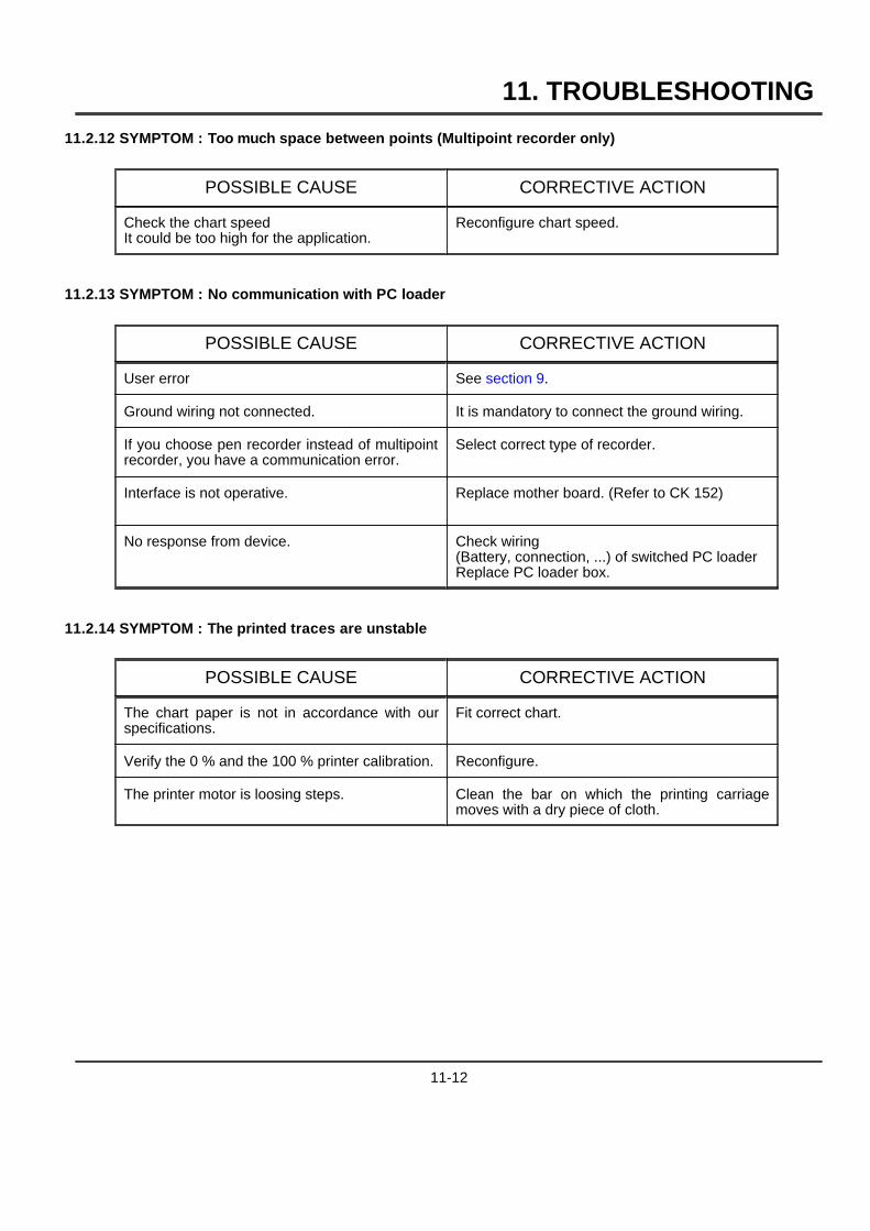
11. TROUBLESHOOTING
11.2.12 SYMPTOM : Too much space between points (Multipoint recorder only)
POSSIBLE CAUSE CORRECTIVE ACTION
Check the chart speedIt could be too high for the application.
Reconfigure chart speed.
11.2.13 SYMPTOM : No communication with PC loader
POSSIBLE CAUSE CORRECTIVE ACTION
User error See section 9.
Ground wiring not connected. It is mandatory to connect the ground wiring.
If you choose pen recorder instead of multipointrecorder, you have a communication error.
Select correct type of recorder.
Interface is not operative. Replace mother board. (Refer to CK 152)
No response from device. Check wiring(Battery, connection, ...) of switched PC loaderReplace PC loader box.
11.2.14 SYMPTOM : The printed traces are unstable
POSSIBLE CAUSE CORRECTIVE ACTION
The chart paper is not in accordance with ourspecifications.
Fit correct chart.
Verify the 0 % and the 100 % printer calibration. Reconfigure.
The printer motor is loosing steps. Clean the bar on which the printing carriagemoves with a dry piece of cloth.
11-12
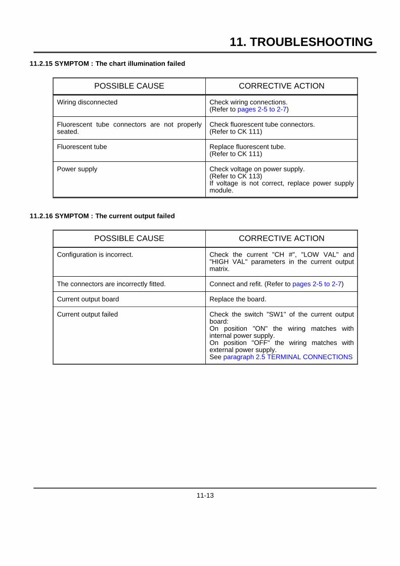
11. TROUBLESHOOTING
11.2.15 SYMPTOM : The chart illumination failed
POSSIBLE CAUSE CORRECTIVE ACTION
Wiring disconnected Check wiring connections.(Refer to pages 2-5 to 2-7)
Fluorescent tube connectors are not properlyseated.
Check fluorescent tube connectors.(Refer to CK 111)
Fluorescent tube Replace fluorescent tube.(Refer to CK 111)
Power supply Check voltage on power supply.(Refer to CK 113)If voltage is not correct, replace power supplymodule.
11.2.16 SYMPTOM : The current output failed
POSSIBLE CAUSE CORRECTIVE ACTION
Configuration is incorrect. Check the current "CH #", "LOW VAL" and"HIGH VAL" parameters in the current outputmatrix.
The connectors are incorrectly fitted. Connect and refit. (Refer to pages 2-5 to 2-7)
Current output board Replace the board.
Current output failed Check the switch "SW1" of the current outputboard:On position "ON" the wiring matches withinternal power supply.On position "OFF" the wiring matches withexternal power supply.See paragraph 2.5 TERMINAL CONNECTIONS
11-13

11. TROUBLESHOOTING
11-14

12. KITS LIST
12-1
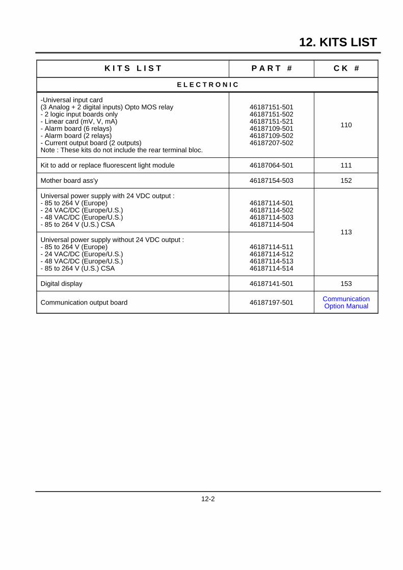
12. KITS LIST
K I T S L I S T P A R T # C K #
E L E C T R O N I C
-Universal input card(3 Analog + 2 digital inputs) Opto MOS relay- 2 logic input boards only- Linear card (mV, V, mA)- Alarm board (6 relays)- Alarm board (2 relays)- Current output board (2 outputs)Note : These kits do not include the rear terminal bloc.
46187151-50146187151-50246187151-52146187109-50146187109-50246187207-502
110
Kit to add or replace fluorescent light module 46187064-501 111
Mother board ass'y 46187154-503 152
Universal power supply with 24 VDC output :- 85 to 264 V (Europe)- 24 VAC/DC (Europe/U.S.)- 48 VAC/DC (Europe/U.S.)- 85 to 264 V (U.S.) CSA
46187114-50146187114-50246187114-50346187114-504
113Universal power supply without 24 VDC output :- 85 to 264 V (Europe)- 24 VAC/DC (Europe/U.S.)- 48 VAC/DC (Europe/U.S.)- 85 to 264 V (U.S.) CSA
46187114-51146187114-51246187114-51346187114-514
Digital display 46187141-501 153
Communication output board 46187197-501 CommunicationOption Manual
12-2
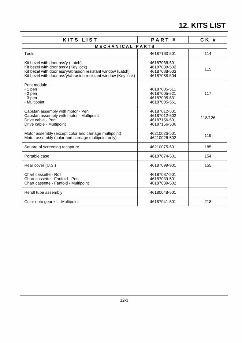
12. KITS LIST
K I T S L I S T P A R T # C K #M E C H A N I C A L P A R T S
Tools 46187163-501 114
Kit bezel with door ass'y (Latch)Kit bezel with door ass'y (Key lock)Kit bezel with door ass'y/abrasion resistant window (Latch)Kit bezel with door ass'y/abrasion resistant window (Key lock)
46187088-50146187088-50246187088-50346187088-504
115
Print module :- 1 pen- 2 pen- 3 pen- Multipoint
46187005-51146187005-52146187005-53146187005-561
117
Capstan assembly with motor - PenCapstan assembly with motor - MultipointDrive cable - PenDrive cable - Multipoint
46187012-50146187012-50246187156-50146187156-506
118/126
Motor assembly (except color and carriage multipoint)Motor assembly (color and carriage multipoint only)
46210026-50146210026-502 119
Square of screening recapture 46210075-501 185
Portable case 46187074-501 154
Rear cover (U.S.) 46187099-901 155
Chart cassette - RollChart cassette - Fanfold - PenChart cassette - Fanfold - Multipoint
46187087-50146187039-50146187039-502
Reroll tube assembly 46180048-501
Color opto gear kit - Multipoint 46187041-501 218
12-3
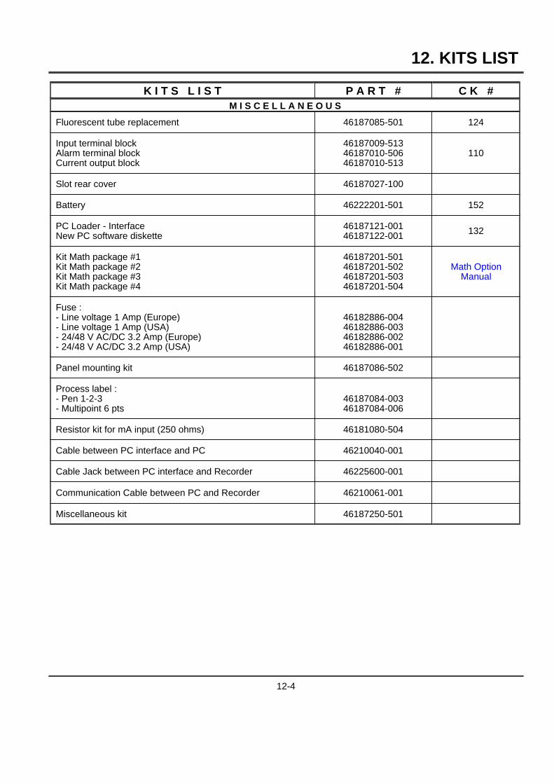
12. KITS LIST
K I T S L I S T P A R T # C K #M I S C E L L A N E O U S
Fluorescent tube replacement 46187085-501 124
Input terminal blockAlarm terminal blockCurrent output block
46187009-51346187010-50646187010-513
110
Slot rear cover 46187027-100
Battery 46222201-501 152
PC Loader - InterfaceNew PC software diskette
46187121-00146187122-001 132
Kit Math package #1Kit Math package #2Kit Math package #3Kit Math package #4
46187201-50146187201-50246187201-50346187201-504
Math OptionManual
Fuse :- Line voltage 1 Amp (Europe)- Line voltage 1 Amp (USA)- 24/48 V AC/DC 3.2 Amp (Europe)- 24/48 V AC/DC 3.2 Amp (USA)
46182886-00446182886-00346182886-00246182886-001
Panel mounting kit 46187086-502
Process label :- Pen 1-2-3- Multipoint 6 pts
46187084-00346187084-006
Resistor kit for mA input (250 ohms) 46181080-504
Cable between PC interface and PC 46210040-001
Cable Jack between PC interface and Recorder 46225600-001
Communication Cable between PC and Recorder 46210061-001
Miscellaneous kit 46187250-501
12-4
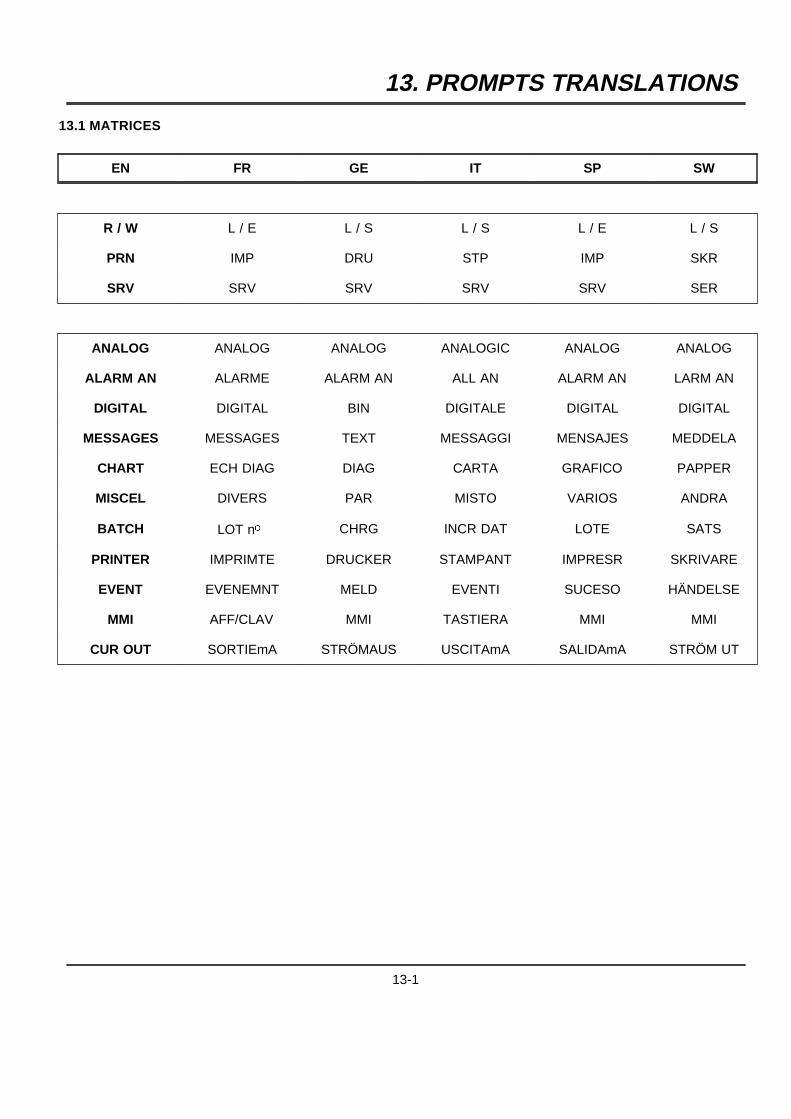
13. PROMPTS TRANSLATIONS
13.1 MATRICES
EN FR GE IT SP SW
R / W L / E L / S L / S L / E L / S
PRN IMP DRU STP IMP SKR
SRV SRV SRV SRV SRV SER
ANALOG ANALOG ANALOG ANALOGIC ANALOG ANALOG
ALARM AN ALARME ALARM AN ALL AN ALARM AN LARM AN
DIGITAL DIGITAL BIN DIGITALE DIGITAL DIGITAL
MESSAGES MESSAGES TEXT MESSAGGI MENSAJES MEDDELA
CHART ECH DIAG DIAG CARTA GRAFICO PAPPER
MISCEL DIVERS PAR MISTO VARIOS ANDRA
BATCH LOT no CHRG INCR DAT LOTE SATS
PRINTER IMPRIMTE DRUCKER STAMPANT IMPRESR SKRIVARE
EVENT EVENEMNT MELD EVENTI SUCESO HÄNDELSE
MMI AFF/CLAV MMI TASTIERA MMI MMI
CUR OUT SORTIEmA STRÖMAUS USCITAmA SALIDAmA STRÖM UT
13-1
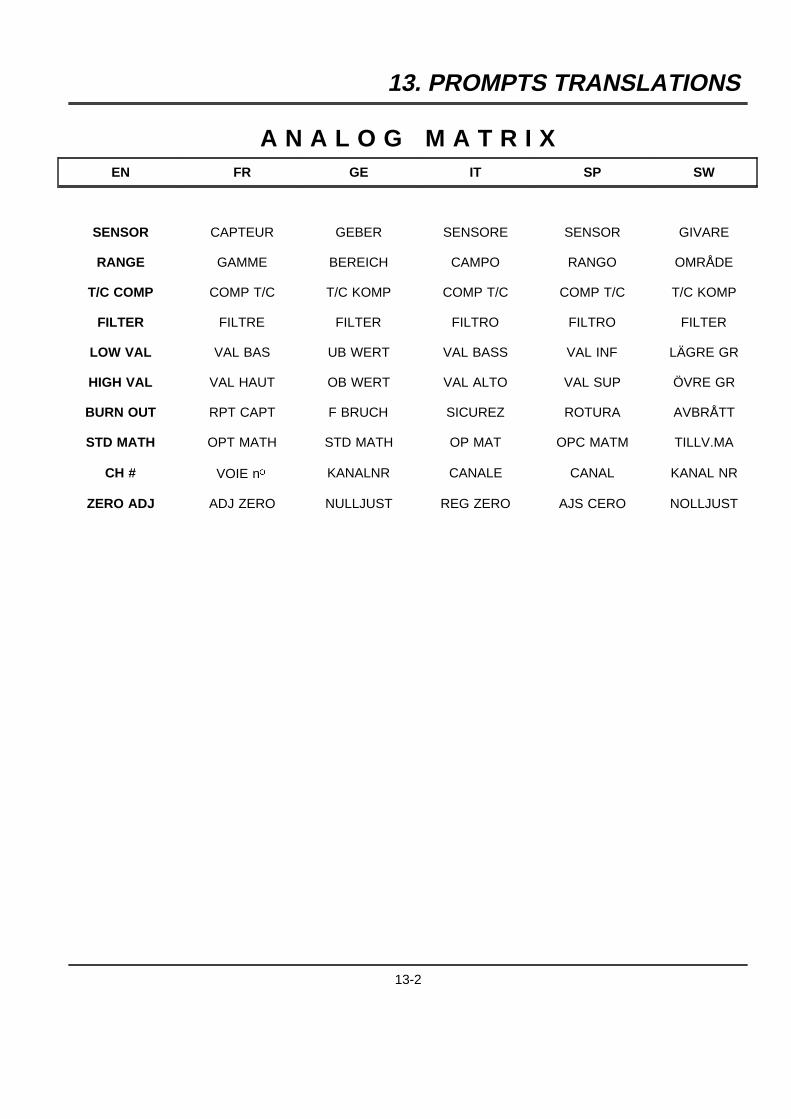
13. PROMPTS TRANSLATIONS
A N A L O G M A T R I XEN FR GE IT SP SW
SENSOR CAPTEUR GEBER SENSORE SENSOR GIVARE
RANGE GAMME BEREICH CAMPO RANGO OMRÅDE
T/C COMP COMP T/C T/C KOMP COMP T/C COMP T/C T/C KOMP
FILTER FILTRE FILTER FILTRO FILTRO FILTER
LOW VAL VAL BAS UB WERT VAL BASS VAL INF LÄGRE GR
HIGH VAL VAL HAUT OB WERT VAL ALTO VAL SUP ÖVRE GR
BURN OUT RPT CAPT F BRUCH SICUREZ ROTURA AVBRÅTT
STD MATH OPT MATH STD MATH OP MAT OPC MATM TILLV.MA
CH # VOIE no KANALNR CANALE CANAL KANAL NR
ZERO ADJ ADJ ZERO NULLJUST REG ZERO AJS CERO NOLLJUST
13-2
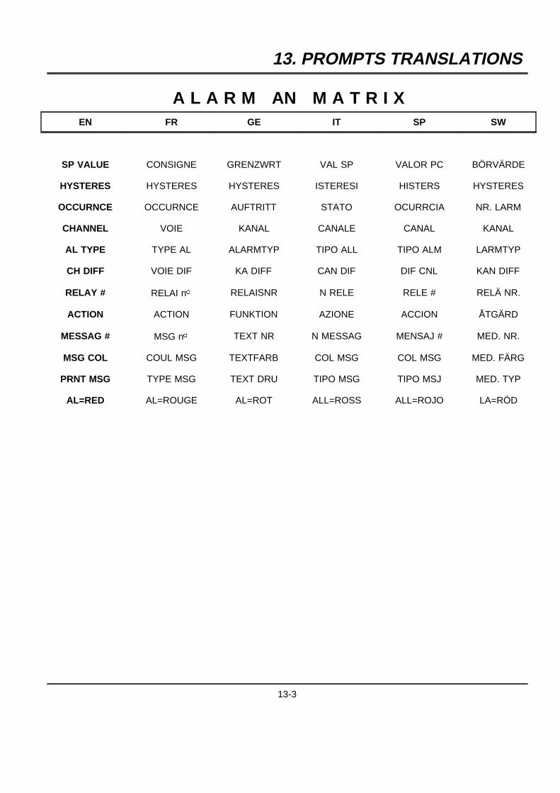
13. PROMPTS TRANSLATIONS
A L A R M AN M A T R I XEN FR GE IT SP SW
SP VALUE CONSIGNE GRENZWRT VAL SP VALOR PC BÖRVÄRDE
HYSTERES HYSTERES HYSTERES ISTERESI HISTERS HYSTERES
OCCURNCE OCCURNCE AUFTRITT STATO OCURRCIA NR. LARM
CHANNEL VOIE KANAL CANALE CANAL KANAL
AL TYPE TYPE AL ALARMTYP TIPO ALL TIPO ALM LARMTYP
CH DIFF VOIE DIF KA DIFF CAN DIF DIF CNL KAN DIFF
RELAY # RELAI no RELAISNR N RELE RELE # RELÄ NR.
ACTION ACTION FUNKTION AZIONE ACCION ÅTGÄRD
MESSAG # MSG no TEXT NR N MESSAG MENSAJ # MED. NR.
MSG COL COUL MSG TEXTFARB COL MSG COL MSG MED. FÄRG
PRNT MSG TYPE MSG TEXT DRU TIPO MSG TIPO MSJ MED. TYP
AL=RED AL=ROUGE AL=ROT ALL=ROSS ALL=ROJO LA=RÖD
13-3
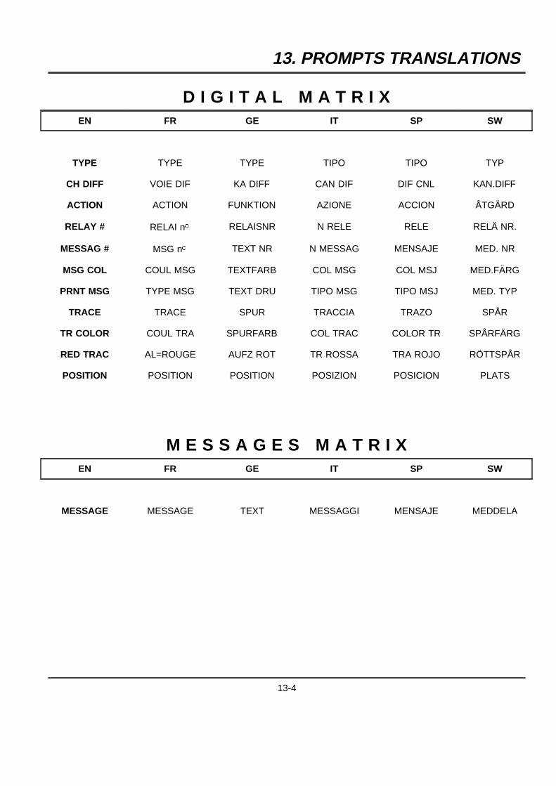
13. PROMPTS TRANSLATIONS
D I G I T A L M A T R I XEN FR GE IT SP SW
TYPE TYPE TYPE TIPO TIPO TYP
CH DIFF VOIE DIF KA DIFF CAN DIF DIF CNL KAN.DIFF
ACTION ACTION FUNKTION AZIONE ACCION ÅTGÄRD
RELAY # RELAI no RELAISNR N RELE RELE RELÄ NR.
MESSAG # MSG no TEXT NR N MESSAG MENSAJE MED. NR
MSG COL COUL MSG TEXTFARB COL MSG COL MSJ MED.FÄRG
PRNT MSG TYPE MSG TEXT DRU TIPO MSG TIPO MSJ MED. TYP
TRACE TRACE SPUR TRACCIA TRAZO SPÅR
TR COLOR COUL TRA SPURFARB COL TRAC COLOR TR SPÅRFÄRG
RED TRAC AL=ROUGE AUFZ ROT TR ROSSA TRA ROJO RÖTTSPÅR
POSITION POSITION POSITION POSIZION POSICION PLATS
M E S S A G E S M A T R I XEN FR GE IT SP SW
MESSAGE MESSAGE TEXT MESSAGGI MENSAJE MEDDELA
13-4
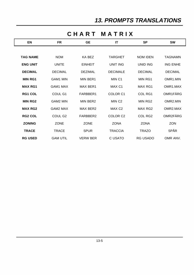
13. PROMPTS TRANSLATIONS
C H A R T M A T R I XEN FR GE IT SP SW
TAG NAME NOM KA BEZ TARGHET NOM IDEN TAGNAMN
ENG UNIT UNITE EINHEIT UNIT ING UNID ING ING ENHE
DECIMAL DECIMAL DEZIMAL DECIMALE DECIMAL DECIMAL
MIN RG1 GAM1 MIN MIN BER1 MIN C1 MIN RG1 OMR1.MIN
MAX RG1 GAM1 MAX MAX BER1 MAX C1 MAX RG1 OMR1.MAX
RG1 COL COUL G1 FARBBER1 COLOR C1 COL RG1 OMR1FÄRG
MIN RG2 GAM2 MIN MIN BER2 MIN C2 MIN RG2 OMR2.MIN
MAX RG2 GAM2 MAX MAX BER2 MAX C2 MAX RG2 OMR2.MAX
RG2 COL COUL G2 FARBBER2 COLOR C2 COL RG2 OMR2FÄRG
ZONING ZONE ZONE ZONA ZONA ZON
TRACE TRACE SPUR TRACCIA TRAZO SPÅR
RG USED GAM UTIL VERW BER C USATO RG USADO OMR ANV.
13-5
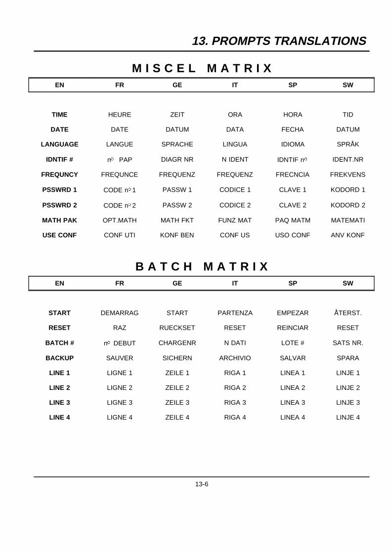
13. PROMPTS TRANSLATIONS
M I S C E L M A T R I XEN FR GE IT SP SW
TIME HEURE ZEIT ORA HORA TID
DATE DATE DATUM DATA FECHA DATUM
LANGUAGE LANGUE SPRACHE LINGUA IDIOMA SPRÅK
IDNTIF # no PAP DIAGR NR N IDENT IDNTIF no IDENT.NR
FREQUNCY FREQUNCE FREQUENZ FREQUENZ FRECNCIA FREKVENS
PSSWRD 1 CODE no1 PASSW 1 CODICE 1 CLAVE 1 KODORD 1
PSSWRD 2 CODE no2 PASSW 2 CODICE 2 CLAVE 2 KODORD 2
MATH PAK OPT.MATH MATH FKT FUNZ MAT PAQ MATM MATEMATI
USE CONF CONF UTI KONF BEN CONF US USO CONF ANV KONF
B A T C H M A T R I XEN FR GE IT SP SW
START DEMARRAG START PARTENZA EMPEZAR ÅTERST.
RESET RAZ RUECKSET RESET REINCIAR RESET
BATCH # no DEBUT CHARGENR N DATI LOTE # SATS NR.
BACKUP SAUVER SICHERN ARCHIVIO SALVAR SPARA
LINE 1 LIGNE 1 ZEILE 1 RIGA 1 LINEA 1 LINJE 1
LINE 2 LIGNE 2 ZEILE 2 RIGA 2 LINEA 2 LINJE 2
LINE 3 LIGNE 3 ZEILE 3 RIGA 3 LINEA 3 LINJE 3
LINE 4 LIGNE 4 ZEILE 4 RIGA 4 LINEA 4 LINJE 4
13-6
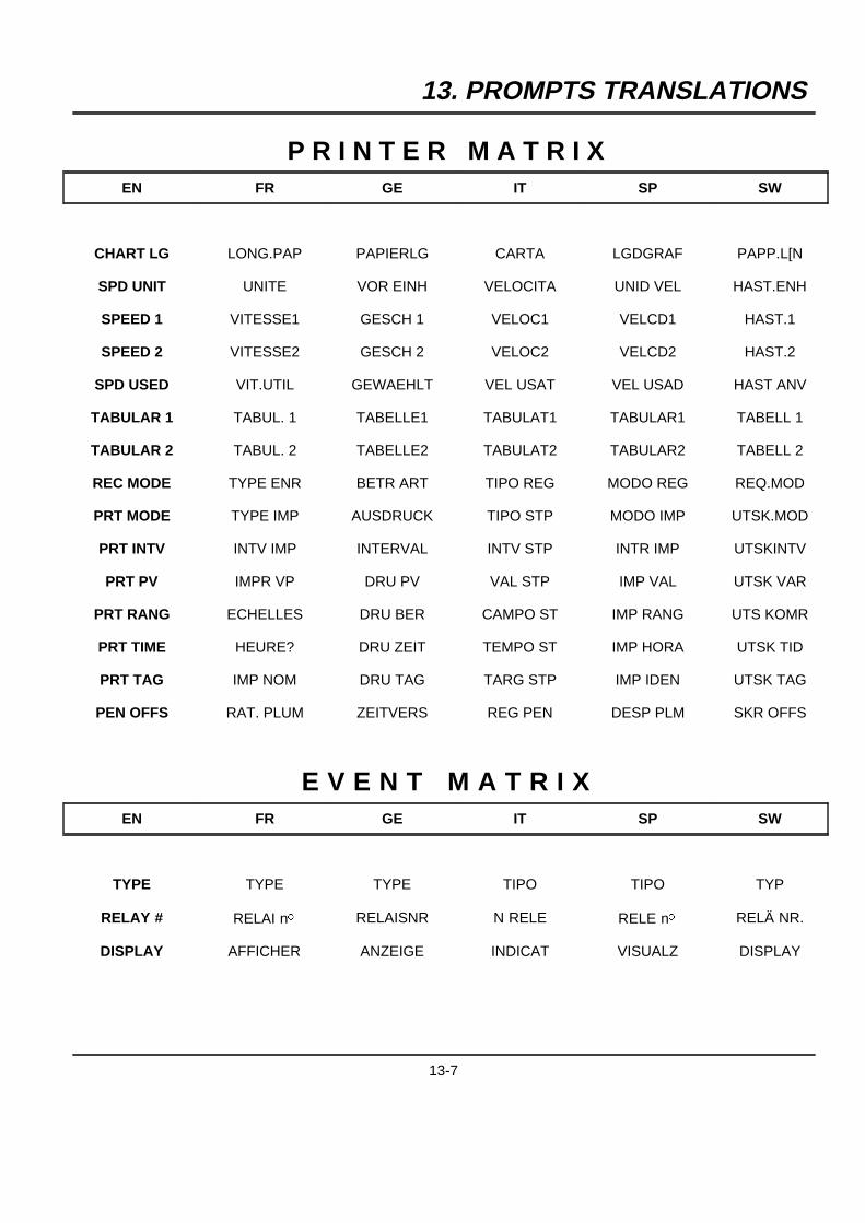
13. PROMPTS TRANSLATIONS
P R I N T E R M A T R I XEN FR GE IT SP SW
CHART LG LONG.PAP PAPIERLG CARTA LGDGRAF PAPP.L[N
SPD UNIT UNITE VOR EINH VELOCITA UNID VEL HAST.ENH
SPEED 1 VITESSE1 GESCH 1 VELOC1 VELCD1 HAST.1
SPEED 2 VITESSE2 GESCH 2 VELOC2 VELCD2 HAST.2
SPD USED VIT.UTIL GEWAEHLT VEL USAT VEL USAD HAST ANV
TABULAR 1 TABUL. 1 TABELLE1 TABULAT1 TABULAR1 TABELL 1
TABULAR 2 TABUL. 2 TABELLE2 TABULAT2 TABULAR2 TABELL 2
REC MODE TYPE ENR BETR ART TIPO REG MODO REG REQ.MOD
PRT MODE TYPE IMP AUSDRUCK TIPO STP MODO IMP UTSK.MOD
PRT INTV INTV IMP INTERVAL INTV STP INTR IMP UTSKINTV
PRT PV IMPR VP DRU PV VAL STP IMP VAL UTSK VAR
PRT RANG ECHELLES DRU BER CAMPO ST IMP RANG UTS KOMR
PRT TIME HEURE? DRU ZEIT TEMPO ST IMP HORA UTSK TID
PRT TAG IMP NOM DRU TAG TARG STP IMP IDEN UTSK TAG
PEN OFFS RAT. PLUM ZEITVERS REG PEN DESP PLM SKR OFFS
E V E N T M A T R I XEN FR GE IT SP SW
TYPE TYPE TYPE TIPO TIPO TYP
RELAY # RELAI no RELAISNR N RELE RELE no RELÄ NR.
DISPLAY AFFICHER ANZEIGE INDICAT VISUALZ DISPLAY
13-7
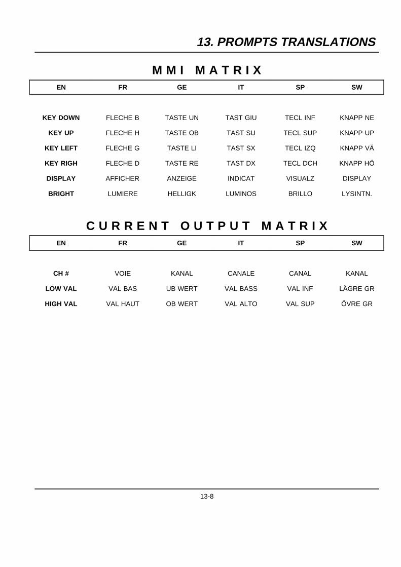
13. PROMPTS TRANSLATIONS
M M I M A T R I XEN FR GE IT SP SW
KEY DOWN FLECHE B TASTE UN TAST GIU TECL INF KNAPP NE
KEY UP FLECHE H TASTE OB TAST SU TECL SUP KNAPP UP
KEY LEFT FLECHE G TASTE LI TAST SX TECL IZQ KNAPP VÄ
KEY RIGH FLECHE D TASTE RE TAST DX TECL DCH KNAPP HÖ
DISPLAY AFFICHER ANZEIGE INDICAT VISUALZ DISPLAY
BRIGHT LUMIERE HELLIGK LUMINOS BRILLO LYSINTN.
C U R R E N T O U T P U T M A T R I XEN FR GE IT SP SW
CH # VOIE KANAL CANALE CANAL KANAL
LOW VAL VAL BAS UB WERT VAL BASS VAL INF LÄGRE GR
HIGH VAL VAL HAUT OB WERT VAL ALTO VAL SUP ÖVRE GR
13-8
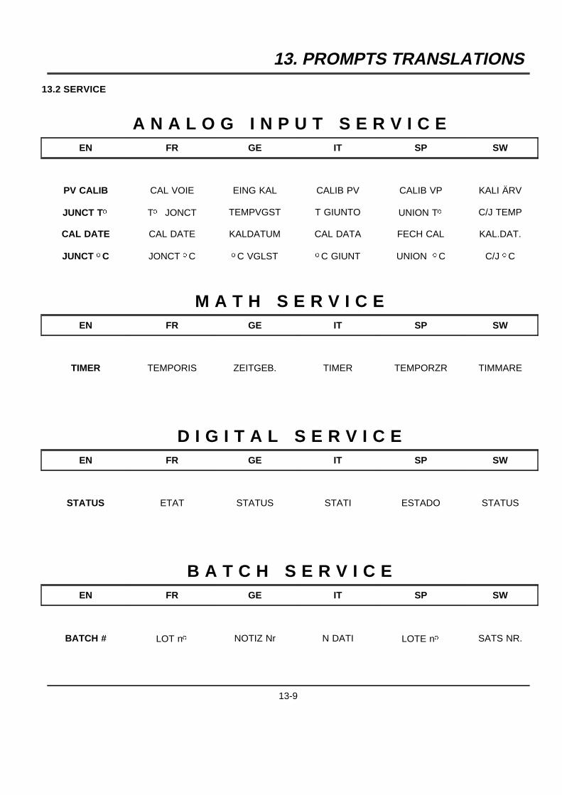
13. PROMPTS TRANSLATIONS
13.2 SERVICE
A N A L O G I N P U T S E R V I C EEN FR GE IT SP SW
PV CALIB CAL VOIE EING KAL CALIB PV CALIB VP KALI ÄRV
JUNCT To To JONCT TEMPVGST T GIUNTO UNION To C/J TEMP
CAL DATE CAL DATE KALDATUM CAL DATA FECH CAL KAL.DAT.
JUNCT oC JONCT oC oC VGLST oC GIUNT UNION oC C/J oC
M A T H S E R V I C EEN FR GE IT SP SW
TIMER TEMPORIS ZEITGEB. TIMER TEMPORZR TIMMARE
D I G I T A L S E R V I C EEN FR GE IT SP SW
STATUS ETAT STATUS STATI ESTADO STATUS
B A T C H S E R V I C EEN FR GE IT SP SW
BATCH # LOT no NOTIZ Nr N DATI LOTE no SATS NR.
13-9
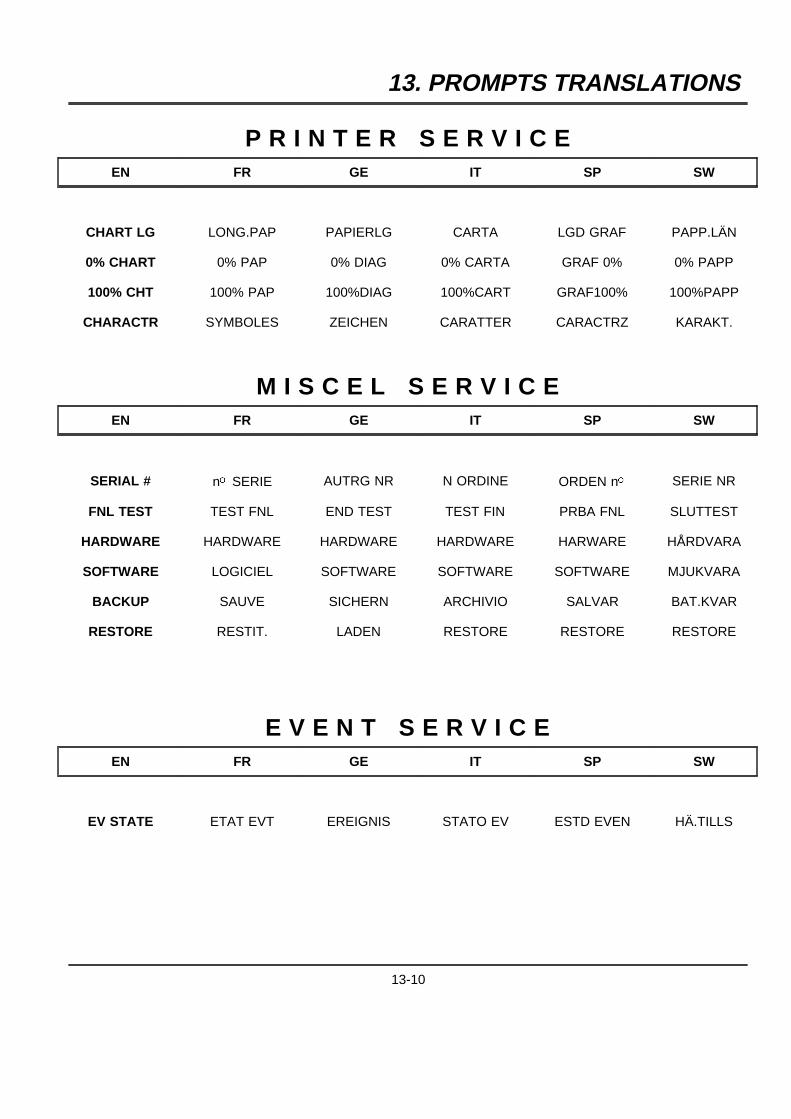
13. PROMPTS TRANSLATIONS
P R I N T E R S E R V I C EEN FR GE IT SP SW
CHART LG LONG.PAP PAPIERLG CARTA LGD GRAF PAPP.LÄN
0% CHART 0% PAP 0% DIAG 0% CARTA GRAF 0% 0% PAPP
100% CHT 100% PAP 100%DIAG 100%CART GRAF100% 100%PAPP
CHARACTR SYMBOLES ZEICHEN CARATTER CARACTRZ KARAKT.
M I S C E L S E R V I C EEN FR GE IT SP SW
SERIAL # no SERIE AUTRG NR N ORDINE ORDEN no SERIE NR
FNL TEST TEST FNL END TEST TEST FIN PRBA FNL SLUTTEST
HARDWARE HARDWARE HARDWARE HARDWARE HARWARE HÅRDVARA
SOFTWARE LOGICIEL SOFTWARE SOFTWARE SOFTWARE MJUKVARA
BACKUP SAUVE SICHERN ARCHIVIO SALVAR BAT.KVAR
RESTORE RESTIT. LADEN RESTORE RESTORE RESTORE
E V E N T S E R V I C EEN FR GE IT SP SW
EV STATE ETAT EVT EREIGNIS STATO EV ESTD EVEN HÄ.TILLS
13-10
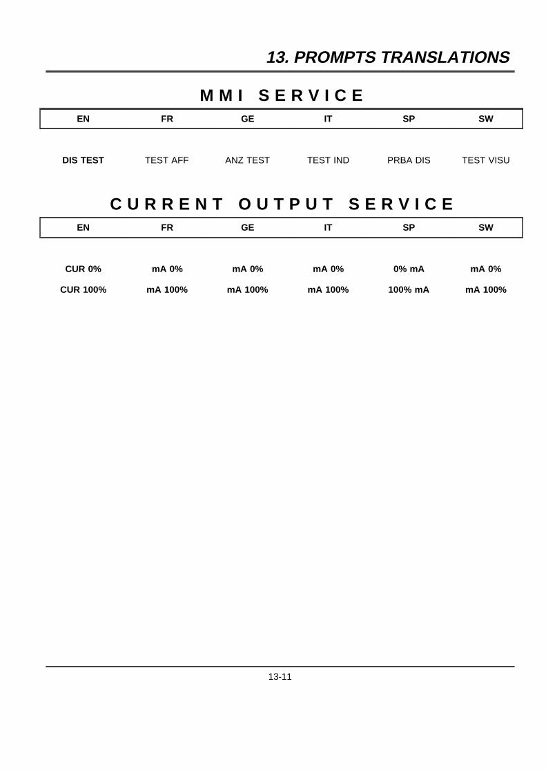
13. PROMPTS TRANSLATIONS
M M I S E R V I C EEN FR GE IT SP SW
DIS TEST TEST AFF ANZ TEST TEST IND PRBA DIS TEST VISU
C U R R E N T O U T P U T S E R V I C EEN FR GE IT SP SW
CUR 0% mA 0% mA 0% mA 0% 0% mA mA 0%
CUR 100% mA 100% mA 100% mA 100% 100% mA mA 100%
13-11
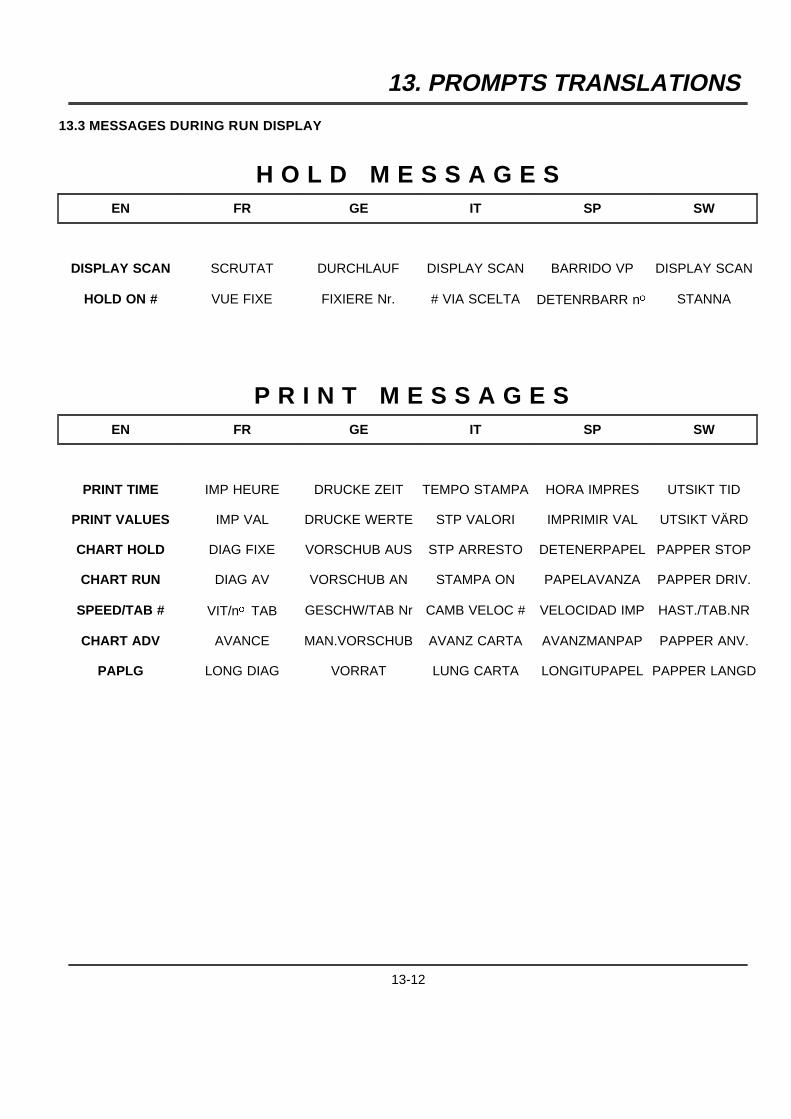
13. PROMPTS TRANSLATIONS
13.3 MESSAGES DURING RUN DISPLAY
H O L D M E S S A G E SEN FR GE IT SP SW
DISPLAY SCAN SCRUTAT DURCHLAUF DISPLAY SCAN BARRIDO VP DISPLAY SCAN
HOLD ON # VUE FIXE FIXIERE Nr. # VIA SCELTA DETENRBARR no STANNA
P R I N T M E S S A G E SEN FR GE IT SP SW
PRINT TIME IMP HEURE DRUCKE ZEIT TEMPO STAMPA HORA IMPRES UTSIKT TID
PRINT VALUES IMP VAL DRUCKE WERTE STP VALORI IMPRIMIR VAL UTSIKT VÄRD
CHART HOLD DIAG FIXE VORSCHUB AUS STP ARRESTO DETENERPAPEL PAPPER STOP
CHART RUN DIAG AV VORSCHUB AN STAMPA ON PAPELAVANZA PAPPER DRIV.
SPEED/TAB # VIT/no TAB GESCHW/TAB Nr CAMB VELOC # VELOCIDAD IMP HAST./TAB.NR
CHART ADV AVANCE MAN.VORSCHUB AVANZ CARTA AVANZMANPAP PAPPER ANV.
PAPLG LONG DIAG VORRAT LUNG CARTA LONGITUPAPEL PAPPER LANGD
13-12
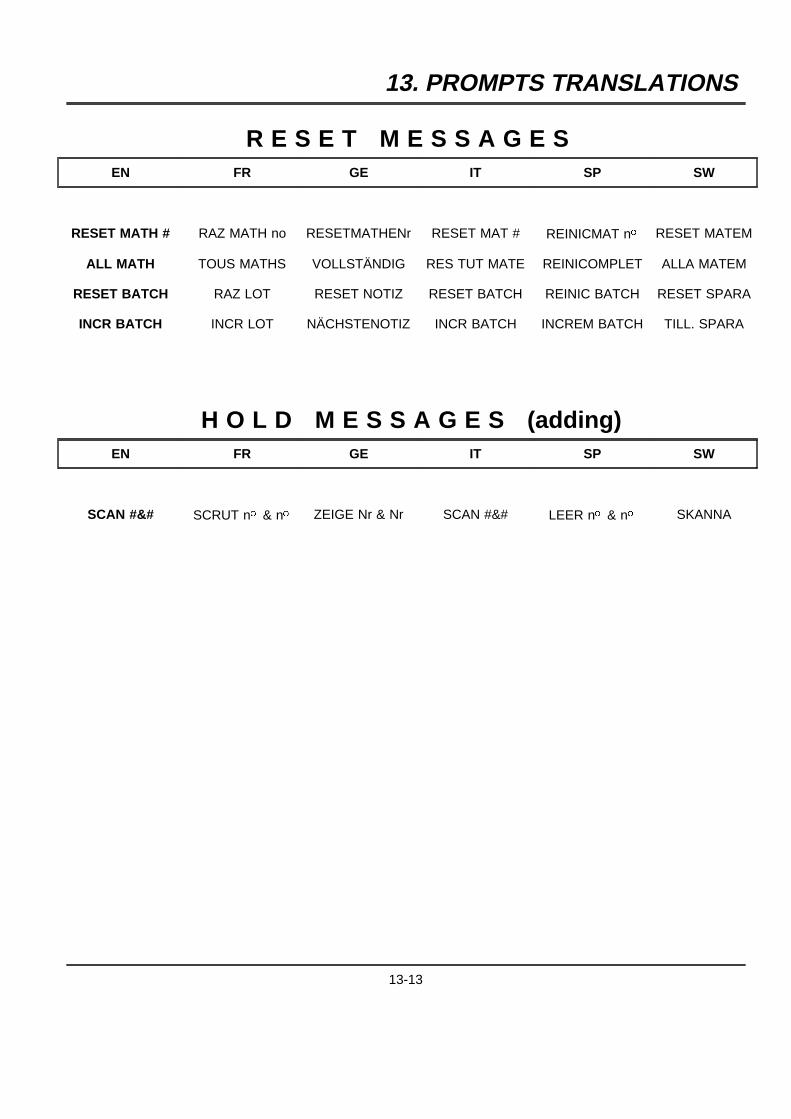
13. PROMPTS TRANSLATIONS
R E S E T M E S S A G E SEN FR GE IT SP SW
RESET MATH # RAZ MATH no RESETMATHENr RESET MAT # REINICMAT no RESET MATEM
ALL MATH TOUS MATHS VOLLSTÄNDIG RES TUT MATE REINICOMPLET ALLA MATEM
RESET BATCH RAZ LOT RESET NOTIZ RESET BATCH REINIC BATCH RESET SPARA
INCR BATCH INCR LOT NÄCHSTENOTIZ INCR BATCH INCREM BATCH TILL. SPARA
H O L D M E S S A G E S (adding)EN FR GE IT SP SW
SCAN #&# SCRUT no & no ZEIGE Nr & Nr SCAN #&# LEER no & no SKANNA
13-13

13. PROMPTS TRANSLATIONS
13-14
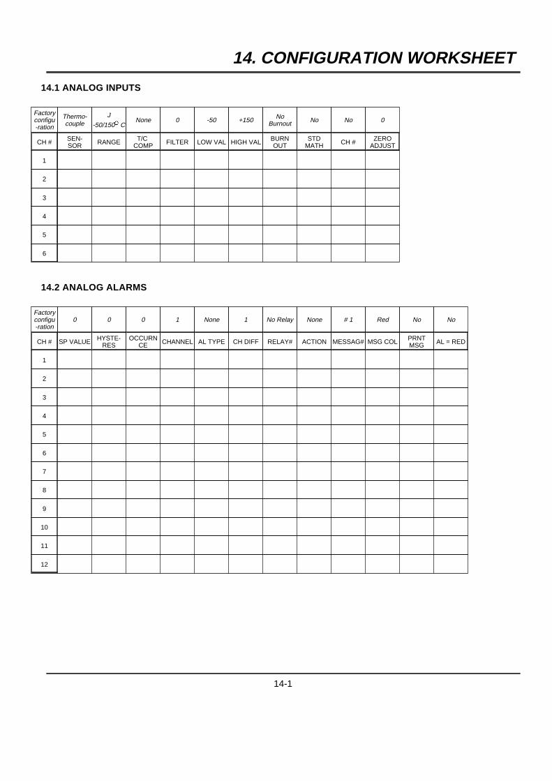
14. CONFIGURATION WORKSHEET
14.1 ANALOG INPUTS
Factoryconfigu-ration
Thermo-couple
J
-50/150oCNone 0 -50 +150 No
Burnout No No 0
CH # SEN-SOR RANGE T/C
COMP FILTER LOW VAL HIGH VAL BURNOUT
STDMATH CH # ZERO
ADJUST
1
2
3
4
5
6
14.2 ANALOG ALARMS
Factoryconfigu-ration
0 0 0 1 None 1 No Relay None # 1 Red No No
CH # SP VALUE HYSTE-RES
OCCURNCE CHANNEL AL TYPE CH DIFF RELAY# ACTION MESSAG# MSG COL PRNT
MSG AL = RED
1
2
3
4
5
6
7
8
9
10
11
12
14-1
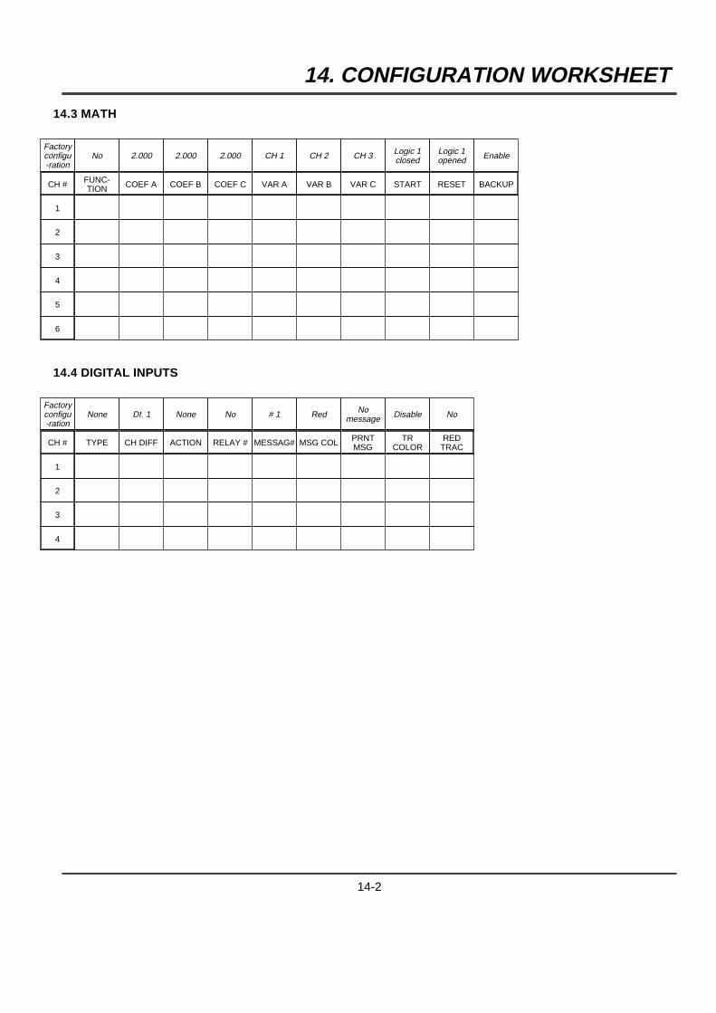
14. CONFIGURATION WORKSHEET
14.3 MATH
Factoryconfigu-ration
No 2.000 2.000 2.000 CH 1 CH 2 CH 3 Logic 1closed
Logic 1opened Enable
CH # FUNC-TION COEF A COEF B COEF C VAR A VAR B VAR C START RESET BACKUP
1
2
3
4
5
6
14.4 DIGITAL INPUTS
Factoryconfigu-ration
None DI. 1 None No # 1 Red Nomessage Disable No
CH # TYPE CH DIFF ACTION RELAY # MESSAG# MSG COL PRNTMSG
TRCOLOR
REDTRAC
1
2
3
4
14-2
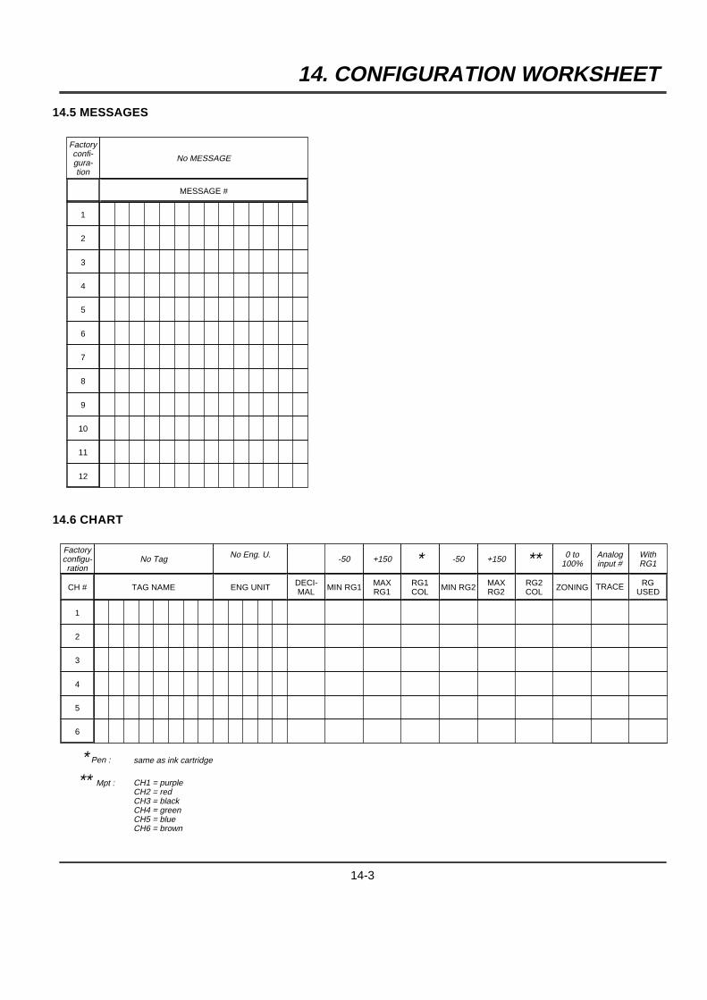
14. CONFIGURATION WORKSHEET
14.5 MESSAGES
Factoryconfi-gura-tion
No MESSAGE
MESSAGE #
1
2
3
4
5
6
7
8
9
10
11
12
14.6 CHART
Factoryconfigu-ration
No Tag No Eng. U. -50 +150 * -50 +150 ** 0 to100%
Analoginput #
WithRG1
CH # TAG NAME ENG UNIT DECI-MAL MIN RG1 MAX
RG1RG1COL MIN RG2 MAX
RG2RG2COL ZONING TRACE RG
USED
1
2
3
4
5
6
* Pen : same as ink cartridge
** Mpt : CH1 = purpleCH2 = redCH3 = blackCH4 = greenCH5 = blueCH6 = brown
14-3
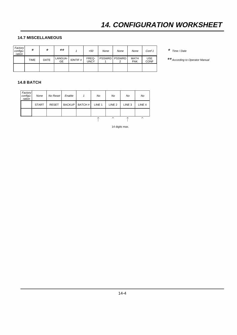
14. CONFIGURATION WORKSHEET
14.7 MISCELLANEOUS
Factoryconfigu-ration
* * ** 1 +50 None None None Conf 1 * Time / Date
TIME DATE LANGUA-GE IDNTIF # FREQ-
UNCYPSSWRD
1PSSWRD
2MATHPAK
USECONF ** According to Operator Manual
14.8 BATCH
Factoryconfigu-ration
None No Reset Enable 1 No No No No
START RESET BACKUP BATCH # LINE 1 LINE 2 LINE 3 LINE 4
F F F F
14 digits max.
14-4
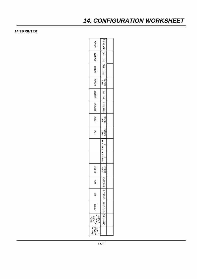
14. CONFIGURATION WORKSHEET
14.9 PRINTER
Fac
tory
conf
igu-
ratio
n
Rol
l=24
000
Fan
fold
=18
000
mm
/h60
120
SP
D1
Prin
tT
rend
120
mm
Ena
ble
Ena
ble
Ena
ble
Dis
able
Dis
able
CH
AR
TLG
SP
DU
NIT
SP
EE
D1
SP
EE
D2
SP
DU
SE
DT
AB
ULA
R1
TA
BU
LAR
2R
EC
MO
DE
PR
TM
OD
EP
RT
INT
VP
RT
PV
PR
TR
AN
GP
RT
TIM
EP
RT
TA
GP
EN
OF
FS
14-5
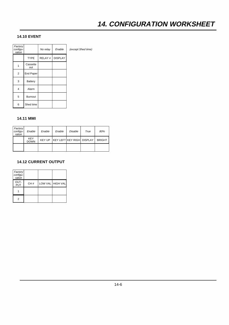
14. CONFIGURATION WORKSHEET
14.10 EVENT
Factoryconfigu-ration
No relay Enable (except Shed time)
TYPE RELAY # DISPLAY
1 Cassetteout
2 End Paper
3 Battery
4 Alarm
5 Burnout
6 Shed time
14.11 MMI
Factoryconfigu-ration
Enable Enable Enable Disable True 80%
KEYDOWN KEY UP KEY LEFT KEY RIGH DISPLAY BRIGHT
14.12 CURRENT OUTPUT
Factoryconfigu-ration
OUT-PUT CH # LOW VAL HIGH VAL
1
2
14-6
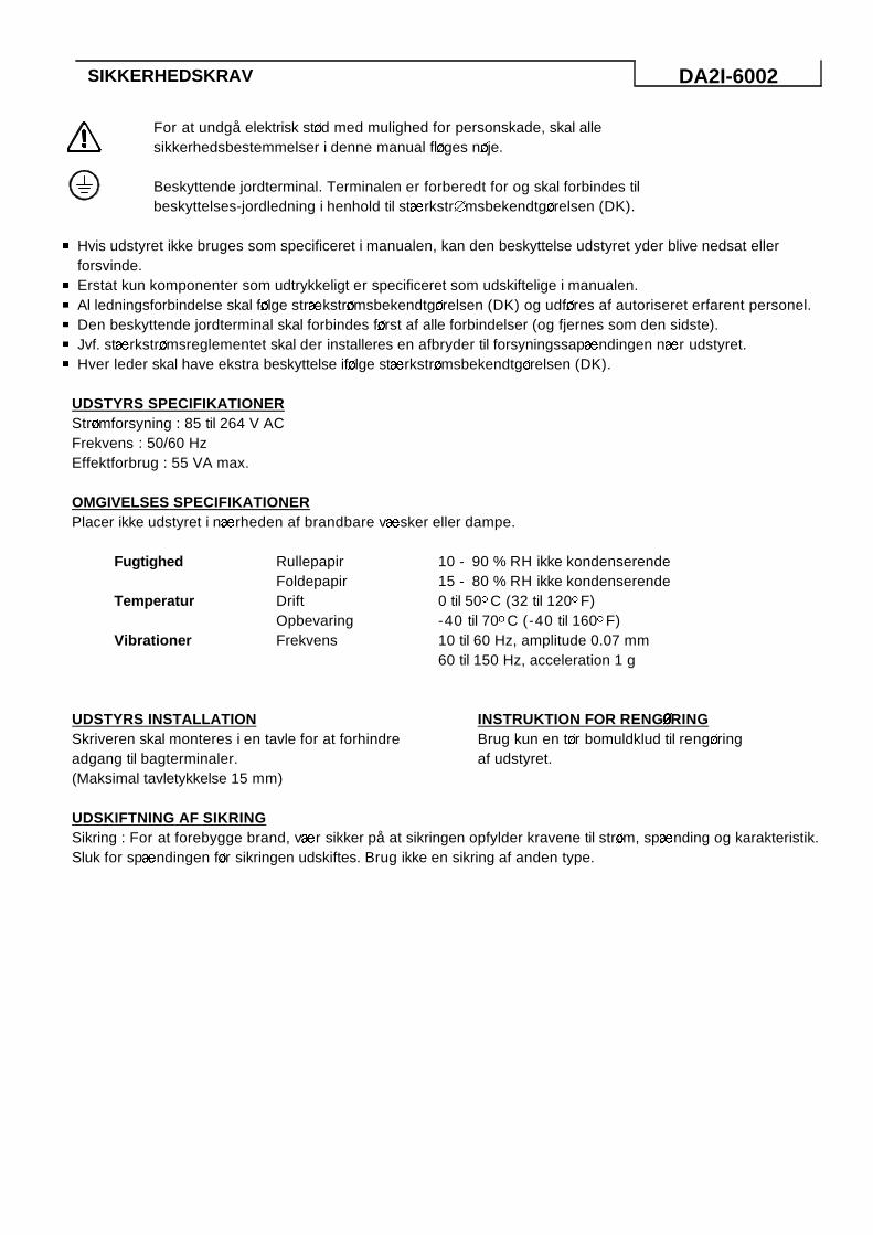
SIKKERHEDSKRAV DA2I-6002
For at undgå elektrisk st\d med mulighed for personskade, skal allesikkerhedsbestemmelser i denne manual fl\ges n\je.
Beskyttende jordterminal. Terminalen er forberedt for og skal forbindes tilbeskyttelses-jordledning i henhold til stABrkstr0msbekendtg\relsen (DK).
4 Hvis udstyret ikke bruges som specificeret i manualen, kan den beskyttelse udstyret yder blive nedsat ellerforsvinde.
4 Erstat kun komponenter som udtrykkeligt er specificeret som udskiftelige i manualen.4 Al ledningsforbindelse skal f\lge strABkstr\msbekendtg\relsen (DK) og udf\res af autoriseret erfarent personel.4 Den beskyttende jordterminal skal forbindes f\rst af alle forbindelser (og fjernes som den sidste).4 Jvf. stABrkstr\msreglementet skal der installeres en afbryder til forsyningssapABndingen nABr udstyret.4 Hver leder skal have ekstra beskyttelse if\lge stABrkstr\msbekendtg\relsen (DK).
UDSTYRS SPECIFIKATIONERStr\mforsyning : 85 til 264 V ACFrekvens : 50/60 HzEffektforbrug : 55 VA max.
OMGIVELSES SPECIFIKATIONERPlacer ikke udstyret i nABrheden af brandbare vABsker eller dampe.
Fugtighed
Temperatur
Vibrationer
RullepapirFoldepapirDriftOpbevaringFrekvens
10 - 90 % RH ikke kondenserende15 - 80 % RH ikke kondenserende0 til 50oC (32 til 120oF)-40 til 70oC (-40 til 160oF)10 til 60 Hz, amplitude 0.07 mm60 til 150 Hz, acceleration 1 g
UDSTYRS INSTALLATIONSkriveren skal monteres i en tavle for at forhindreadgang til bagterminaler.(Maksimal tavletykkelse 15 mm)
INSTRUKTION FOR RENGCRINGBrug kun en t\r bomuldklud til reng\ringaf udstyret.
UDSKIFTNING AF SIKRINGSikring : For at forebygge brand, vABr sikker på at sikringen opfylder kravene til str\m, spABnding og karakteristik.Sluk for spABndingen f\r sikringen udskiftes. Brug ikke en sikring af anden type.
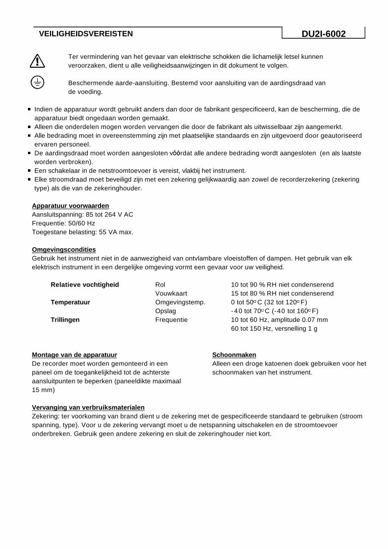
VEILIGHEIDSVEREISTEN DU2I-6002
Ter vermindering van het gevaar van elektrische schokken die lichamelijk letsel kunnenveroorzaken, dient u alle veiligheidsaanwijzingen in dit dokument te volgen.
Beschermende aarde-aansluiting. Bestemd voor aansluiting van de aardingsdraad vande voeding.
4 Indien de apparatuur wordt gebruikt anders dan door de fabrikant gespecificeerd, kan de bescherming, die deapparatuur biedt ongedaan worden gemaakt.
4 Alleen die onderdelen mogen worden vervangen die door de fabrikant als uitwisselbaar zijn aangemerkt.4 Alle bedrading moet in overeenstemming zijn met plaatselijke standaards en zijn uitgevoerd door geautoriseerd
ervaren personeel.4 De aardingsdraad moet worden aangesloten v[[rdat alle andere bedrading wordt aangesloten (en als laatste
worden verbroken).4 Een schakelaar in de netstroomtoevoer is vereist, vlakbij het instrument.4 Elke stroomdraad moet beveiligd zijn met een zekering gelijkwaardig aan zowel de recorderzekering (zekering
type) als die van de zekeringhouder.
Apparatuur voorwaardenAansluitspanning: 85 tot 264 V ACFrequentie: 50/60 HzToegestane belasting: 55 VA max.
OmgevingsconditiesGebruik het instrument niet in de aanwezigheid van ontvlambare vloeistoffen of dampen. Het gebruik van elkelektrisch instrument in een dergelijke omgeving vormt een gevaar voor uw veiligheid.
Relatieve vochtigheid
Temperatuur
Trillingen
RolVouwkaartOmgevingstemp.OpslagFrequentie
10 tot 90 % RH niet condenserend15 tot 80 % RH niet condenserend0 tot 50oC (32 tot 120oF)-40 tot 70oC (-40 tot 160oF)10 tot 60 Hz, amplitude 0.07 mm60 tot 150 Hz, versnelling 1 g
Montage van de apparatuurDe recorder moet worden gemonteerd in eenpaneel om de toegankelijkheid tot de achtersteaansluitpunten te beperken (paneeldikte maximaal15 mm)
SchoonmakenAlleen een droge katoenen doek gebruiken voor hetschoonmaken van het instrument.
Vervanging van verbruiksmaterialenZekering: ter voorkoming van brand dient u de zekering met de gespecificeerde standaard te gebruiken (stroomspanning, type). Voor u de zekering vervangt moet u de netspanning uitschakelen en de stroomtoevoeronderbreken. Gebruik geen andere zekering en sluit de zekeringhouder niet kort.
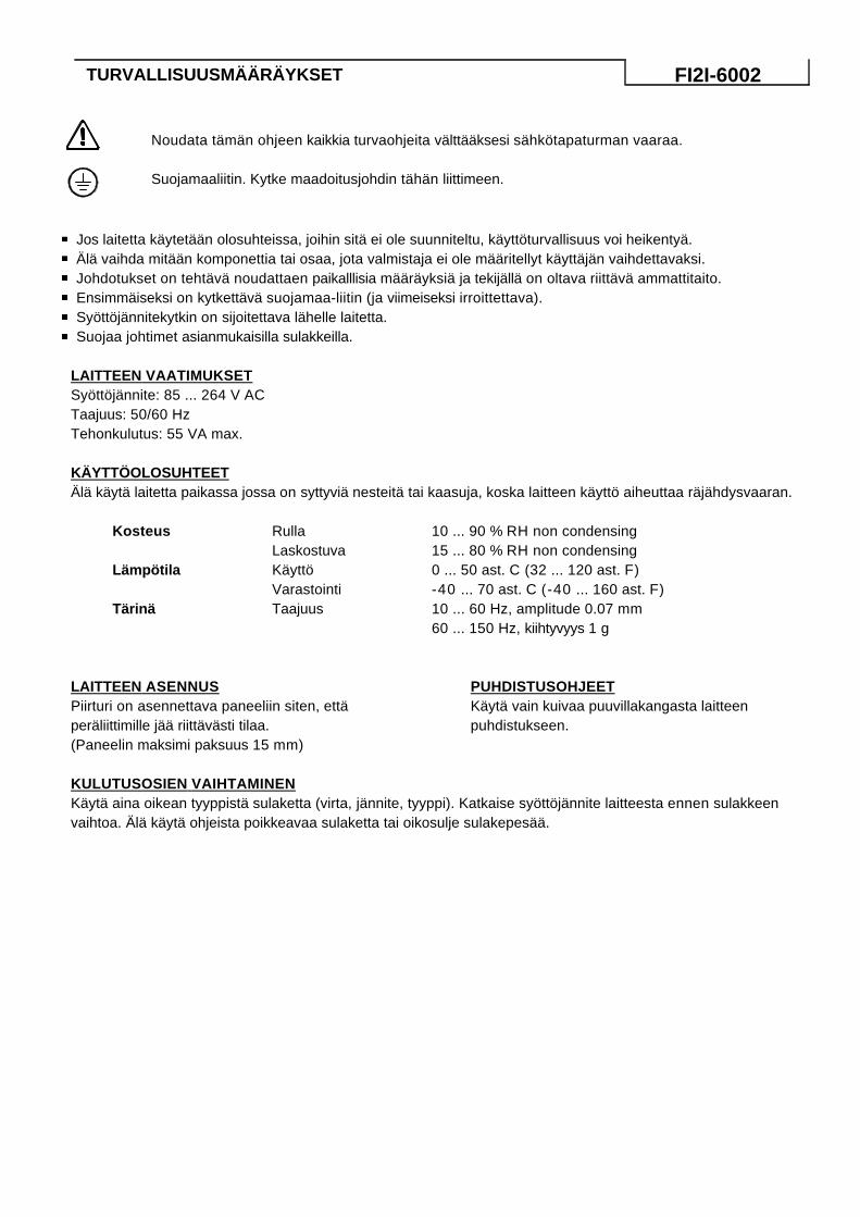
TURVALLISUUSMÄÄRÄYKSET FI2I-6002
Noudata tämän ohjeen kaikkia turvaohjeita välttääksesi sähkötapaturman vaaraa.
Suojamaaliitin. Kytke maadoitusjohdin tähän liittimeen.
4 Jos laitetta käytetään olosuhteissa, joihin sitä ei ole suunniteltu, käyttöturvallisuus voi heikentyä.4 Älä vaihda mitään komponettia tai osaa, jota valmistaja ei ole määritellyt käyttäjän vaihdettavaksi.4 Johdotukset on tehtävä noudattaen paikalllisia määräyksiä ja tekijällä on oltava riittävä ammattitaito.4 Ensimmäiseksi on kytkettävä suojamaa-liitin (ja viimeiseksi irroittettava).4 Syöttöjännitekytkin on sijoitettava lähelle laitetta.4 Suojaa johtimet asianmukaisilla sulakkeilla.
LAITTEEN VAATIMUKSETSyöttöjännite: 85 ... 264 V ACTaajuus: 50/60 HzTehonkulutus: 55 VA max.
KÄYTTÖOLOSUHTEETÄlä käytä laitetta paikassa jossa on syttyviä nesteitä tai kaasuja, koska laitteen käyttö aiheuttaa räjähdysvaaran.
Kosteus
Lämpötila
Tärinä
RullaLaskostuvaKäyttöVarastointiTaajuus
10 ... 90 % RH non condensing15 ... 80 % RH non condensing0 ... 50 ast. C (32 ... 120 ast. F)-40 ... 70 ast. C (-40 ... 160 ast. F)10 ... 60 Hz, amplitude 0.07 mm60 ... 150 Hz, kiihtyvyys 1 g
LAITTEEN ASENNUSPiirturi on asennettava paneeliin siten, ettäperäliittimille jää riittävästi tilaa.(Paneelin maksimi paksuus 15 mm)
PUHDISTUSOHJEETKäytä vain kuivaa puuvillakangasta laitteenpuhdistukseen.
KULUTUSOSIEN VAIHTAMINENKäytä aina oikean tyyppistä sulaketta (virta, jännite, tyyppi). Katkaise syöttöjännite laitteesta ennen sulakkeenvaihtoa. Älä käytä ohjeista poikkeavaa sulaketta tai oikosulje sulakepesää.

APAITHSEIS ASFALEIAS GR2I-6002
GIA NA MEIWQEI O KINDYNOS HLEKTROPLHXIAS H OPOIA MPOREI NA
PROKALESEI TRAYMATISMO, AKOLOYQEISTE, OLES TIS ODHGIES ASFALEIAS POY
PARATIQENTAI S' AYTO TO FYLLADIO.
PROSTATEYTIKH GEIWSH. PARECETAI GIA THN SYNDESH ME TO SYSTHMA GEIWSHS
THS EGKATASTASHS.
4 AN H SYSKEYH CRHSIMOPOIHQEI ME TROPO POY DEN SYMFWNEI ME TIS ODHGIES TOY KATASKEYASTH
PIQANON NA MEIWQEI H PROSTASIA POY PROSFEREI.4 NA MHN ANTIKAQISTATAI KANENA EXARTHMA H' TMHMA TOY ORGANOY POY DEN ANAFERETAI SAFWS
APO TON KATASKEYASTH WS ANTALLAXIMO.4 OLES OI KALWDIWSEIS PREPEI NA EINAI SYMFWNES ME THN TOPIKH NOMOQESIA KAI H EGKATASTASH
TOYS PREPEI NA GINEI APO EIDIKEYMENO KAI EMPEIRO PROSWPIKO.4 H GEIWSH PREPEI NA SYNDEQEI PRIN APO OPOIADHPOTE ALLH KALWDIWSH, KAI TELEYTAIA KATA THN
APOSYNDESH.4 ENAS DIAKOPTHS THS KYRIAS PAROCHS APAITEITAI KONTA STO ORGANO.4 KAQE KALWDIO PREPEI NA PROSTATEYETAI APO ASFALEIA ISODYNAMH ME THN ASFALEIA TOY
KATAGRAFIKOY, KAQWS EPISHS KAI ME ASFALEIOQHKH.
TECNIKA STOICEIA ORGANOY
TROFODOSIA : 85 - 264 V ac
SYCNOTHTA : 50/60 Hz
ISCYS : 55 VA MEGISTH
SYNQHKES PERIBALLONTOS
NA MHN CRHSIMOPOIEITAI TO ORGANO SE CWROYS ME PAROYSIA EYLEKTWN YGRWN H ATMWN.
CRHSH OPOIOYDHPOTE HLEKTRIKOY ORGANOY SE TETOIO PERIBALLON APOTELEI KINDYNO
ATYCHMATOS.
YGRASIA
QERMOKRASIA
TALANTWSH
CARTI ROLLO
CARTI DIPLWMENO
PERIBALLONTOS
APOQHKEYSHS
SYCNOTHTA
10 - 90 % RH MH SYMPYKNWMENH
15 - 80 % RH MH SYMPYKNWMENH
0 / 50 DEG C (32 / 120 DEG F)- 40 / 70 DEG C ( - 40 / 160 DEG F)
10 - 60 Hz, MEGEQOS 0.07 mm
60 - 150 Hz, EPITACYNSH 1 g
TOPOQETHSH MHCANHMATOS
TO KATAGRAFIKO ORGANO PREPEI NA
TOPOQETHQEI STHN PROSOVH TOY PINAKA ,
ETSI WSTE NA MHN MPOREI O CEIRISTHS NA
ECEI PROSBASH STO PISW MEROS. MEGISTO
PACOS PINAKOS 15 mm.
ODHGIES KAQARISMOY
CRHSIMOPOIHSTE MONO ENA STEGNO
BAMBAKERO YFASMA GIA TON KAQARISMO TOY
ORGANOY.
ANTIKATASTASH ANALWSIMOY YLIKOY
ASFALEIA : PROS APOFYGH PYRKAIAS H ASFALEIA QA PREPEI NA ANTIKAQISTATAI ME NEA, BASH TWN
PROTEINOMENWN PRODIAGRAFWN (TASH, ENTASH, TYPOS ). PRIN APO THN ANTIKATASTASH NA
DIAKOPTETAI H PAROCH TASHS H' NA APOSYNDEETAI H KALWDIWSH PAROCHS. NA MHN
CRHSIMOPOIHTAI ASFALEIA DIAFORETIKH APO THN PROTEINOMENH, KAI NA MHN BRACYKYKLWNETAI
H ASFALEIOQHKH.
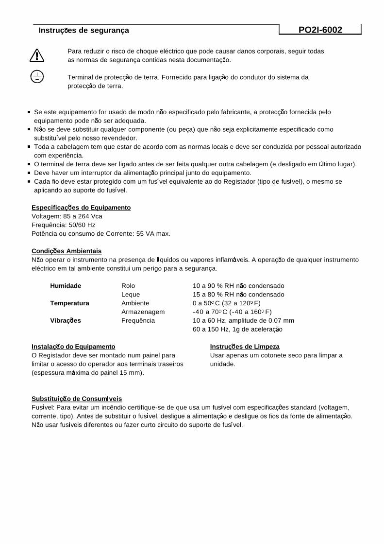
InstruçBes de segurança PO2I-6002
Para reduzir o risco de choque eléctrico que pode causar danos corporais, seguir todasas normas de segurança contidas nesta documentaçAo.
Terminal de protecçAo de terra. Fornecido para ligaçAo do condutor do sistema daprotecçAo de terra.
4 Se este equipamento for usado de modo nAo especificado pelo fabricante, a protecçAo fornecida peloequipamento pode nAo ser adequada.
4 NAo se deve substituir qualquer componente (ou peça) que nAo seja explicitamente especificado comosubstitu&vel pelo nosso revendedor.
4 Toda a cabelagem tem que estar de acordo com as normas locais e deve ser conduzida por pessoal autorizadocom experiência.
4 O terminal de terra deve ser ligado antes de ser feita qualquer outra cabelagem (e desligado em |ltimo lugar).4 Deve haver um interruptor da alimentaçAo principal junto do equipamento.4 Cada fio deve estar protegido com um fus&vel equivalente ao do Registador (tipo de fus&vel), o mesmo se
aplicando ao suporte do fus&vel.
EspecificaçBes do EquipamentoVoltagem: 85 a 264 VcaFrequência: 50/60 HzPotência ou consumo de Corrente: 55 VA max.
CondiçBes AmbientaisNAo operar o instrumento na presença de l&quidos ou vapores inflam@veis. A operaçAo de qualquer instrumentoeléctrico em tal ambiente constitui um perigo para a segurança.
Humidade
Temperatura
VibraçBes
RoloLequeAmbienteArmazenagemFrequência
10 a 90 % RH nAo condensado15 a 80 % RH nAo condensado0 a 50oC (32 a 120oF)-40 a 70oC (-40 a 160oF)10 a 60 Hz, amplitude de 0.07 mm60 a 150 Hz, 1g de aceleraçAo
InstalaçAo do EquipamentoO Registador deve ser montado num painel paralimitar o acesso do operador aos terminais traseiros(espessura m@xima do painel 15 mm).
InstruçBes de LimpezaUsar apenas um cotonete seco para limpar aunidade.
SubstituiçAo de Consum&veisFus&vel: Para evitar um incêndio certifique-se de que usa um fus&vel com especificaçBes standard (voltagem,corrente, tipo). Antes de substituir o fus&vel, desligue a alimentaçAo e desligue os fios da fonte de alimentaçAo.NAo usar fus&veis diferentes ou fazer curto circuito do suporte de fus&vel.
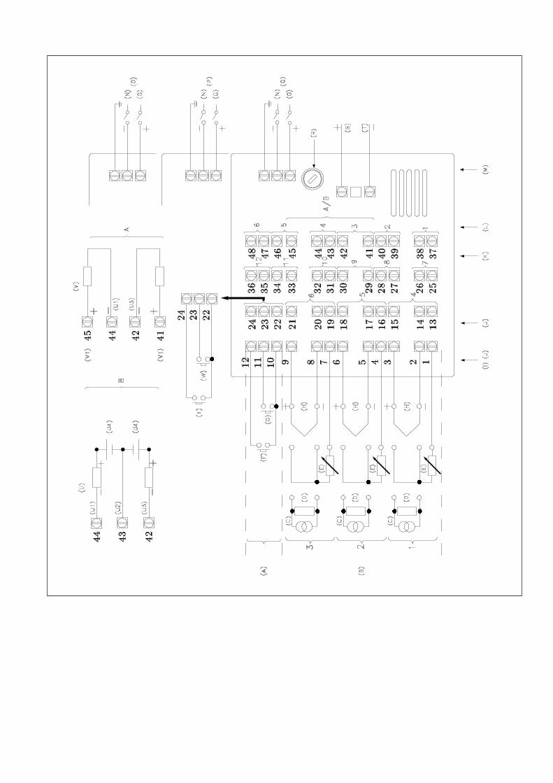

PO
(A) Entradas l[gicas(B) Entradas anal[gicas(C) mA(D) 250 ohms(E) RTD(F) L2(G) L1(H) T/C, mV, V(I) Entradas anal[gicas para registador de caneta(J) Entradas anal[gicas para registador multiponto(K) 7 a 12 sa&das de alarme(L) 1 a 6 sa&das de alarme ou 1 a 2 sa&das corrente(M) Fonte de alimentaçAo(N) L2/N(O) 24 V ca/cc(P) 48 V ca/cc(Q) 100 a 240 V ca/cc(R) Fus&vel de 100 a 240 V ca = 1 A24 ou 48 V ca/cc = 3.2 A(S) Saida de 24 V cc(T) M@ximo de 75 mA(U) Gerador externo(U1) OUT 2(U2) 0 V(U3) OUT 1(U4) 24 V DC max.(V) Gerador interno(V1) +12 V(W) L3(X) L4
DU
(A) Logische ingangen(B) Analoge ingangen(C) mA(D) 250 ohm(E) RTD(F) L2(G) L1(H) T/C, mV, V(I) Analoge ingangen, pen recorder(J) Analoge ingangen, meerpunts recorder(K) 7 tot 12 alarm uitgangen(L) 1 tot 6 alarm uitgangen of 1 tot 2 stroomuitgangen(M) Netvoeding(N) L2/N(O) 24 V AC/DC(P) 48 V AC/DC(Q) 100 tot 240 V AC/DC(R) Zekering 100 tot 240 V AC = 1 A24 of 48 V AC/DC = 3.2 A(S) 24 V DC uitgang(T) 75 mA max.(U) Externe generator(U1) OUT 2(U2) 0 V(U3) OUT 1(U4) 24 V DC max.(V) Interne generator(V1) +12 V(W) L3(X) L4

GR
(A) LOGIKH EISODOS(B) ANALOGIKH EISODOS(C) mA(D) 250 ohms(E) RTD(F) L2(G) L1(H) T/C, mV, V(I) ANALOGIKES EISODOI KATAGRAFIKHS
PENNAS(J) ANALOGIKES EISODOI KATAGRAFIKOY
POLLAPLWN EGGRAFWN(K) 7 - 12 SYNAGERMOI EXODOY(L) 1 - 6 SYNAGERMOI EXODOY H'
1 - 2 REYMATA EXODOY(M) TROFODOSIA(N) L2/N(O) 24 V AC/DC(P) 48 V AC/DC(Q) 100 - 240 V AC/DC(R) ASFALEIA(S) EXODOS SYNECHS TASHS(T) EXWTERIKH / ESWTERIKH TROFODOSIA(U) EXOTERIKH GENNHTRIA(U1) OUT 2(U2) 0 V(U3) OUT 1(U4) 24 V DC max.(V) ESOTERIKH GENNHTRIA(V1) +12 V(W) L3(X) L4
DA
(A) Logiske indgange(B) Analoge indgange(C) mA(D) 250 Ohm(E) RTD (PT 100)(F) L2(G) L1(H) T/C, mV, V(I) Analoge indgange linieskriver(J) Analoge indgange multipunktskriver(K) 7 til 12 alarm udgange(L) 1 til 6 alarm udgange eller 1 til 2 str\mudgange(M) Str\mforsyning(N) L2/N(O) 24 V AC/DC(P) 48 V AC/DC(Q) 100 - 240 V AC/DC(R) Sikring 100 - 240 V AC = 1 A24 eller 48 V AC/DC = 3.2 A(S) 24 V DC udgang(T) 75 mA max.(U) Extern generator(U1) OUT 2(U2) 0 V(U3) OUT 1(U4) 24 V DC max.(V) Intern generator(V1) +12 V(W) L3(X) L4

FI
(A) Logiikkatulot(B) Analogiatulot(C) mA(D) 250 ohms(E) RTD(F) L2(G) L1(H) T/C, mV, V(I) Analogiatulot kynäpiirturi(J) Analogiatulot monipistepiirturi(K) 7 ... 12 hälytyslähdöt(L) 1 ... 6 hälytyslähdöt tai 1 ... 2 virtalähdöt(M) Jännitelähde(N) L2/N(O) 24 V AC/DC(P) 48 V AC/DC(Q) 100 ... 240 V AC/DC(R) Sulake 100 ... 240 V AC = 1 A24 tai 48 V AC/DC = 3.2 A(S) 24 V DC lähtö(T) 75 mA max.(U) External generator(U1) OUT 2(U2) 0 V(U3) OUT 1(U4) 24 V DC max.(V) Internal generator(V1) +12 V(W) L3(X) L4
