honeywell connected life safety services hw-tg7laf02 …
TRANSCRIPT
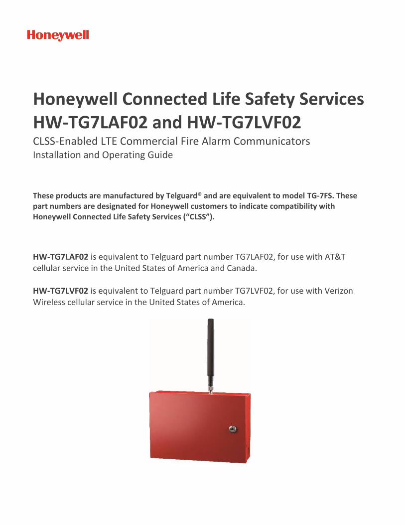
Honeywell Connected Life Safety Services HW-TG7LAF02 and HW-TG7LVF02 CLSS-Enabled LTE Commercial Fire Alarm Communicators Installation and Operating Guide
These products are manufactured by Telguard® and are equivalent to model TG-7FS. These part numbers are designated for Honeywell customers to indicate compatibility with Honeywell Connected Life Safety Services (“CLSS”). HW-TG7LAF02 is equivalent to Telguard part number TG7LAF02, for use with AT&T cellular service in the United States of America and Canada. HW-TG7LVF02 is equivalent to Telguard part number TG7LVF02, for use with Verizon Wireless cellular service in the United States of America.
LS10265-000HW-E:C 04/27/2021 ii 56052901 – Rev B
GETTING STARTED WITH HONEYWELL CONNECTED LIFE SAFETY SERVICES This guide with help you with the steps that you need to follow to configure the HW-TG7LAF02 and HW-TG7LVf02 devices with Honeywell Connected Life Safety Services (CLSS). Honeywell CLSS is a cloud platform that enables systems integrators and facilities managers to deliver an enhanced fire safety service, while maximizing the performance efficiencies offered by Honeywell's trusted detection and alarm systems. By harnessing the power of data, it delivers the connectivity and intelligence needed for secure, compliant, and more efficient fire system management. Utilizing the CLSS platform in conjunction with the CLSS LTE Fire Communicator enables users to access valuable tools to monitor and manage their fire systems.
1. CONFIGURE THE DEVICE WITH CLSS
If you already have a CLSS Account: 1. Open the CLSS app and login. 2. Tap the Navigation menu in the upper right corner, then tap Install Dialer Capture. 3. Follow the on-screen instructions to configure the device.
If you do not yet have a CLSS Account:
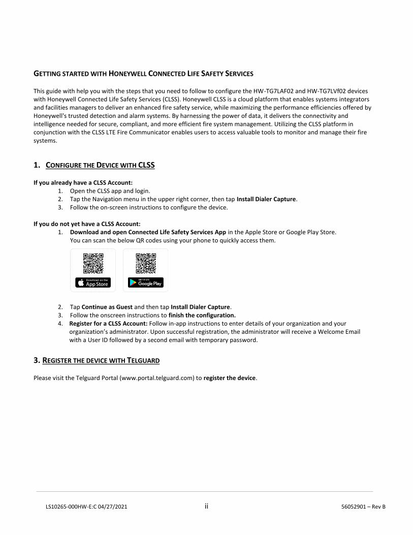
1. Download and open Connected Life Safety Services App in the Apple Store or Google Play Store. You can scan the below QR codes using your phone to quickly access them.
2. Tap Continue as Guest and then tap Install Dialer Capture. 3. Follow the onscreen instructions to finish the configuration. 4. Register for a CLSS Account: Follow in-app instructions to enter details of your organization and your
organization’s administrator. Upon successful registration, the administrator will receive a Welcome Email with a User ID followed by a second email with temporary password.
3. REGISTER THE DEVICE WITH TELGUARD Please visit the Telguard Portal (www.portal.telguard.com) to register the device.

COMPANY CONFIDENTIAL For use by TELGUARD® customers only. Distribution to other parties strictly prohibited. February 7, 2020
Telguard TG-7 Series Installation and Operating Guide for models TG-7, TG-7A, TG-7FS, TG-Kit, and TG-7UBL

LS10265-000HW-E:C 04/27/2021 i 56052901 – Rev B
Important Note
The registration form must be completed before leaving for the job site to install the Telguard product. Use our dealer site at www.telguard.com to register the unit in real time.
Foreword
Dealers purchase Telguard® cellular communicators for the quality, features and total value they represent. The Telguard TG-7 models (TG-7, TG-7A, TG-7FS, TG-KIT, TG-UBL) are UL Listed for Household Burglary systems, Household Fire systems, Commercial Burglary and depending on the model, Commercial Fire systems. The Telguard TG-7 models may be used in Household Burglary/Fire systems and Retail or Commercial Burglary/Fire systems as the sole, primary or secondary communication path.
Technical Support
Technical support for all Telguard products is available:
Monday -Saturday 8am -8pm ET
Toll Free: 800-229-2326, option 9
About this Manual
This manual assumes that you have basic security system installation skills such as measuring voltages, stripping wire, properly connecting wires together, connecting wires to terminals, and checking phone lines. It also assumes that you have a familiarity with the proper installation and programming tasks related to various alarm panels.
The material and instructions covered in this manual have been carefully checked for accuracy and are presumed to be reliable. However, Telguard assumes no responsibility for inaccuracies and reserves the right to modify and revise this manual without notice.
It is our goal at Telguard to always supply accurate and reliable documentation. If a discrepancy is found in this documentation, please mail or fax a photocopy of the corrected material to:
Telguard Technical Services 3225 Cumberland Blvd Suite 300 Atlanta, GA USA 30339 Fax: 678-945-1651
LS10265-000HW-E:C 04/27/2021 ii 56052901 – Rev B
Repair and Warranty
If trouble is experienced with the Telguard Cellular Alarm Communicator please contact Telguard Technical Support for trouble shooting, repair and (or) warranty information. The dealer or end user should not attempt any repair to the Telguard Cellular Alarm Communicator. Repair of this equipment should only be referred to qualified technical personnel.
Telguard will repair or replace (our option) inoperative units for up to two years from date of manufacture. This excludes damage due to lightning or installer error. Unauthorized modifications void this warranty. Not responsible for incidental or consequential damages. Liability is limited to price of unit. This is the exclusive warranty and no other warranties will be honored, whether expressed or implied.
An RMA must be assigned before returning product. You may obtain an RMA via phone at 800-229-2326 option 1, or via email at [email protected].
Note: RMA number must be on the outside of box or product will not be accepted.
Future Testing and Limitations on Use
The Telguard TG-7 Series is part of an advanced design alarm communication system. It does not offer guaranteed protection against burglary and fire. Any alarm communication system is subject to compromise or failure.
The Telguard unit will not work without power. Electrically powered devices will not work if the power supply is off for any reason, however briefly.
The cellular radio network, needed to transmit alarm signals from protected premises to a central monitoring station, may be inoperable or temporarily out of service. Cellular radio networks are also subject to compromise by sophisticated methods of attack.
This equipment, like any other electrical device, is subject to component failure. Although this equipment is designed to be long lasting, the electrical components could fail at any time.
Due to these limitations, we recommend that if the automatic self-test feature is not enabled, other arrangements be made with the user to test the system at least once every three months. Moreover, arrangements should also be made for on-site inspection/test by a licensed alarm installer at least once each year.
Terms and Conditions for Use of Telguard Product
These Terms and Conditions are a legal contract between you and Telguard for the title to and use of the Product. BY RETAINING AND USING THE PRODUCT YOU AGREE TO THE TERMS AND CONDITIONS INCLUDING WARRANTY DISCLAIMERS, LIMITATIONS OF LIABILITY AND INDEMNIFICATION PROVISIONS BELOW. IF YOU DO NOT AGREE TO THE TERMS AND CONDITIONS, DO NOT USE THE PRODUCT AND IMMEDIATELY RETURN THE UNUSED PRODUCT FOR A COMPLETE REFUND. You agree to accept sole responsibility for any misuse of the Product by you; and, in addition, any negligent or illegal act or omission of you or your agents, contractors, servants, employees, or other users of the Product so long as the Product was obtained from you, in the use and operation of the Product.
LS10265-000HW-E:C 04/27/2021 iii 56052901 – Rev B
INDEMNIFICATION OF TELGUARD
YOU SHALL INDEMNIFY, DEFEND AND HOLD HARMLESS TELGUARD FOR ANY OF THE COST, INCLUDING REASONABLE ATTORNEYS’ FEES, AND FROM CLAIMS ARISING OUT OF YOUR, YOUR CLIENTS’ OR OTHER THIRD PARTIES’ USE OR OPERATION OF THE PRODUCT: (i) FOR MISUSE OR IN A MANNER NOT CONTEMPLATED BY YOU AND TELGUARD OR INCONSISTENT WITH THE PROVISIONS OF THIS MANUAL; (ii) IN AN ILLEGAL MANNER OR AGAINST PUBLIC POLICY; (iii) IN A MANNER SPECIFICALLY UNAUTHORIZED IN THIS MANUAL; (iv) IN A MANNER HARMFUL OR DANGEROUS TO THIRD PARTIES; (v) FROM CLAIMS BY ANYONE RESPECTING PROBLEMS, ERRORS OR MISTAKES OF THE PRODUCT; OR (vi) COMBINATION OF THE PRODUCT WITH MATERIAL, MODIFICATION OF THE PRODUCT OR USE OF THE PRODUCT IN AN ENVIRONMENT NOT PROVIDED, OR PERMITTED, BY TELGUARD IN WRITING. THE PARTIES SHALL GIVE EACH OTHER PROMPT NOTICE OF ANY SUCH COST OR CLAIMS AND COOPERATE, EACH WITH THE OTHER, TO EFFECTUATE THIS INDEMNIFICATION, DEFENSE AND HOLD HARMLESS.
WARRANTY and LIMITATIONS
TELGUARD WILL REPAIR OR REPLACE (OUR OPTION) INOPERATIVE UNITS FOR UP TO TWO YEARS FROM DATE OF MANUFACTURE. EXCLUDES DAMAGE DUE TO LIGHTNING OR INSTALLER ERROR AS WELL AS UNITS THAT INCORPORATE MATERIAL, OR USED IN A MANNER OR ENVIRONMENT, NOT SPECIFICALLY AUTHORIZED IN THIS MANUAL. UNAUTHORIZED MODIFICATIONS VOID THIS WARRANTY. NOT RESPONSIBLE FOR INCIDENTAL OR CONSEQUENTIAL DAMAGES. LIABILITY LIMITED TO PRICE OF UNIT. THIS IS THE EXCLUSIVE WARRANTY, IN LIEU OF ALL OTHER WARRANTIES INCLUDING IMPLIED WARRANTIES OF MERCHANTABILITY, TITLE, DELIVERY, INFRINGEMENT OR FITNESS FOR A PARTICULAR PURPOSE AND NO OTHER WARRANTIES WILL BE HONORED, WHETHER EXPRESSED OR IMPLIED.
LS10265-000HW-E:C 04/27/2021 iv 56052901 – Rev B
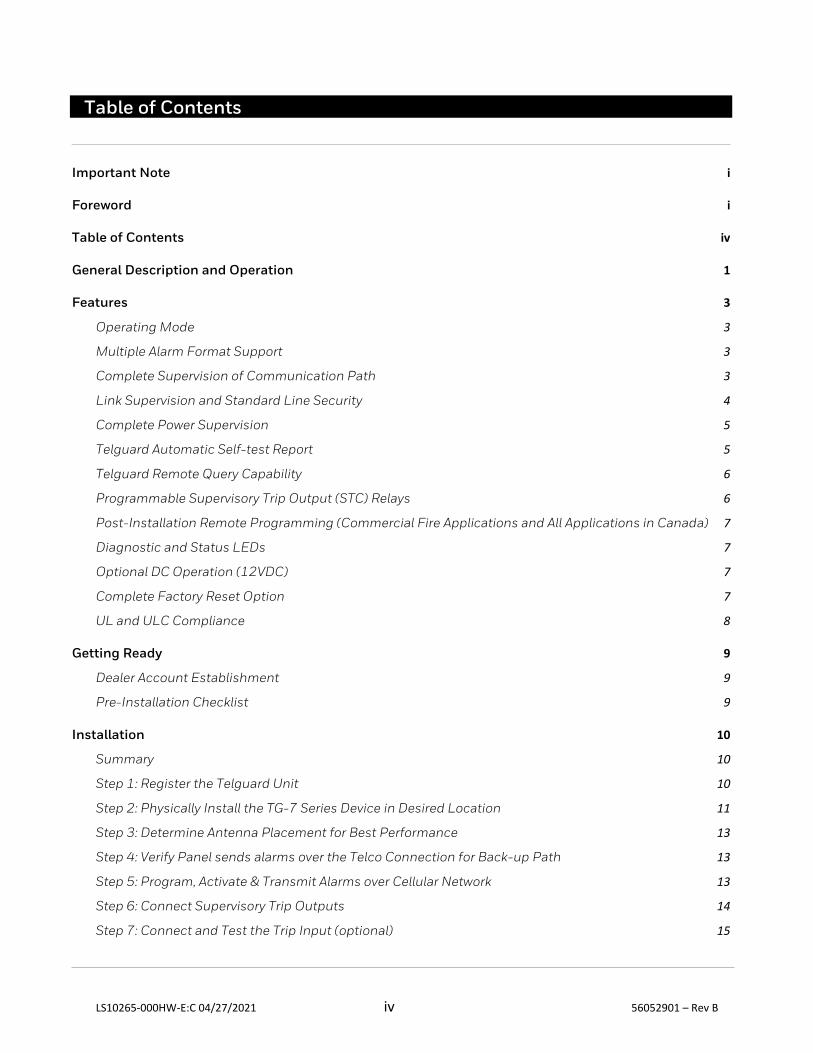
Table of Contents
Important Note i
Foreword i
Table of Contents iv
General Description and Operation 1
Features 3
Operating Mode 3
Multiple Alarm Format Support 3
Complete Supervision of Communication Path 3
Link Supervision and Standard Line Security 4
Complete Power Supervision 5
Telguard Automatic Self-test Report 5
Telguard Remote Query Capability 6
Programmable Supervisory Trip Output (STC) Relays 6
Post-Installation Remote Programming (Commercial Fire Applications and All Applications in Canada) 7
Diagnostic and Status LEDs 7
Optional DC Operation (12VDC) 7
Complete Factory Reset Option 7
UL and ULC Compliance 8
Getting Ready 9
Dealer Account Establishment 9
Pre-Installation Checklist 9
Installation 10
Summary 10
Step 1: Register the Telguard Unit 10
Step 2: Physically Install the TG-7 Series Device in Desired Location 11
Step 3: Determine Antenna Placement for Best Performance 13
Step 4: Verify Panel sends alarms over the Telco Connection for Back-up Path 13
Step 5: Program, Activate & Transmit Alarms over Cellular Network 13
Step 6: Connect Supervisory Trip Outputs 14
Step 7: Connect and Test the Trip Input (optional) 15

LS10265-000HW-E:C 04/27/2021 v 56052901 – Rev B
Step 8: Connect Tamper Switch (mandatory for Commercial Burglary Installations in Canada) 15
Appendix 1 – Connection Guide 17
Wiring Diagrams 17
Tamper Switch Installation for UL/ULC Commercial Burglary Applications 22
Jack Assignments 23
Main Terminal Strip Pin Assignments 23
DC Terminal Strip Pin Assignments 23
A/C Terminal Strip Pin Assignments 23
Compatible Alarm Panels 24
Appendix 2 – Troubleshooting Guide 25
LED Indicator Guide – Normal Operating Mode 25
LED Indicator Guide – RSSI Mode 26
Troubleshooting Quick Reference Table 27
Appendix 3 – Commercial Fire Sole Path Communicator Installation 28
Configuring the TG-7FS 28
Configuring a Sole Path at the Panel 28
Appendix 4 – Commercial Fire 6-hour Supervision 29
Appendix 5 – Compliance with UL and ULC Standards 29
Appendix 6 – Detailed Specifications 31
Dialer to Interface Electronics 31
Power 31
Digital Cellular Radio and Other Specifications 31
Appendix 7 – Accessories 32
LS10265-000HW-E:C 04/27/2021 1 56052901 – Rev B
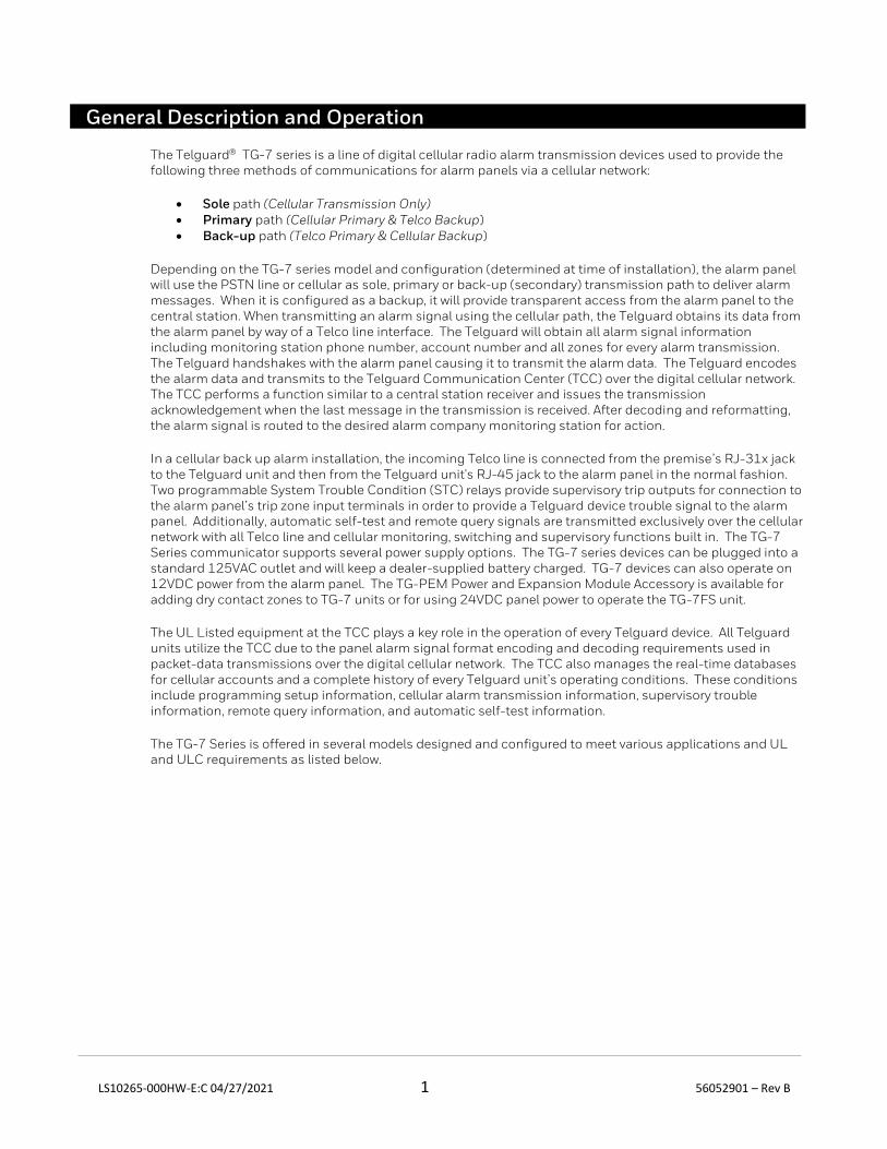
General Description and Operation
The Telguard TG-7 series is a line of digital cellular radio alarm transmission devices used to provide the following three methods of communications for alarm panels via a cellular network:
• Sole path (Cellular Transmission Only) • Primary path (Cellular Primary & Telco Backup) • Back-up path (Telco Primary & Cellular Backup)
Depending on the TG-7 series model and configuration (determined at time of installation), the alarm panel will use the PSTN line or cellular as sole, primary or back-up (secondary) transmission path to deliver alarm messages. When it is configured as a backup, it will provide transparent access from the alarm panel to the central station. When transmitting an alarm signal using the cellular path, the Telguard obtains its data from the alarm panel by way of a Telco line interface. The Telguard will obtain all alarm signal information including monitoring station phone number, account number and all zones for every alarm transmission. The Telguard handshakes with the alarm panel causing it to transmit the alarm data. The Telguard encodes the alarm data and transmits to the Telguard Communication Center (TCC) over the digital cellular network. The TCC performs a function similar to a central station receiver and issues the transmission acknowledgement when the last message in the transmission is received. After decoding and reformatting, the alarm signal is routed to the desired alarm company monitoring station for action.
In a cellular back up alarm installation, the incoming Telco line is connected from the premise’s RJ-31x jack to the Telguard unit and then from the Telguard unit's RJ-45 jack to the alarm panel in the normal fashion. Two programmable System Trouble Condition (STC) relays provide supervisory trip outputs for connection to the alarm panel’s trip zone input terminals in order to provide a Telguard device trouble signal to the alarm panel. Additionally, automatic self-test and remote query signals are transmitted exclusively over the cellular network with all Telco line and cellular monitoring, switching and supervisory functions built in. The TG-7 Series communicator supports several power supply options. The TG-7 series devices can be plugged into a standard 125VAC outlet and will keep a dealer-supplied battery charged. TG-7 devices can also operate on 12VDC power from the alarm panel. The TG-PEM Power and Expansion Module Accessory is available for adding dry contact zones to TG-7 units or for using 24VDC panel power to operate the TG-7FS unit.
The UL Listed equipment at the TCC plays a key role in the operation of every Telguard device. All Telguard units utilize the TCC due to the panel alarm signal format encoding and decoding requirements used in packet-data transmissions over the digital cellular network. The TCC also manages the real-time databases for cellular accounts and a complete history of every Telguard unit’s operating conditions. These conditions include programming setup information, cellular alarm transmission information, supervisory trouble information, remote query information, and automatic self-test information.
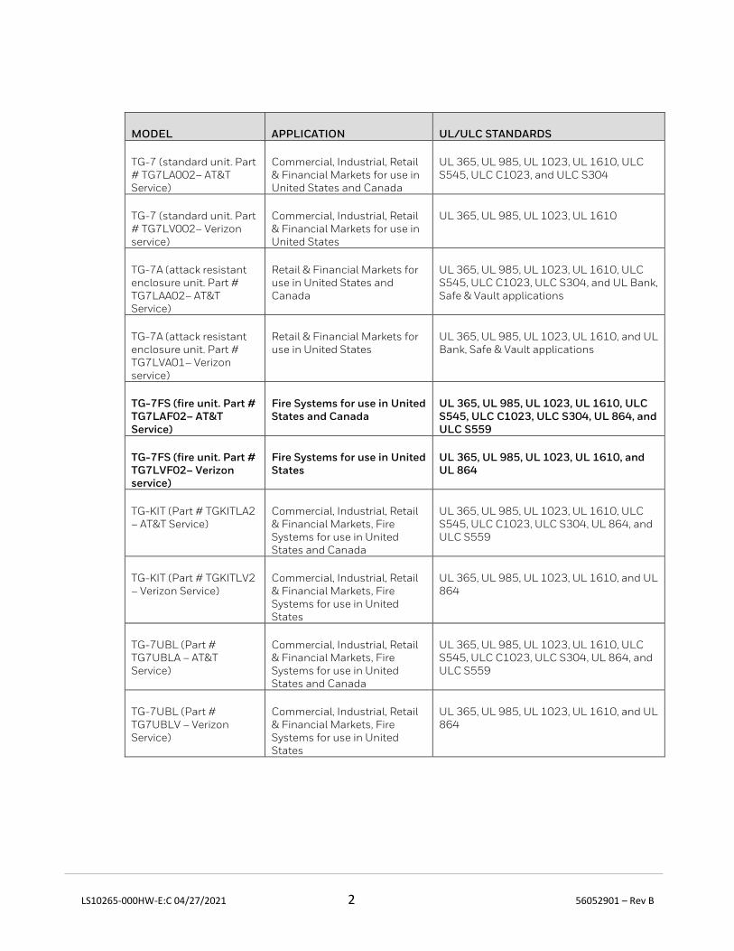
The TG-7 Series is offered in several models designed and configured to meet various applications and UL and ULC requirements as listed below.
LS10265-000HW-E:C 04/27/2021 2 56052901 – Rev B
MODEL APPLICATION UL/ULC STANDARDS
TG-7 (standard unit. Part # TG7LA002– AT&T Service)
Commercial, Industrial, Retail & Financial Markets for use in United States and Canada
UL 365, UL 985, UL 1023, UL 1610, ULC S545, ULC C1023, and ULC S304
TG-7 (standard unit. Part # TG7LV002– Verizon service)
Commercial, Industrial, Retail & Financial Markets for use in United States
UL 365, UL 985, UL 1023, UL 1610
TG-7A (attack resistant enclosure unit. Part # TG7LAA02– AT&T Service)
Retail & Financial Markets for use in United States and Canada
UL 365, UL 985, UL 1023, UL 1610, ULC S545, ULC C1023, ULC S304, and UL Bank, Safe & Vault applications
TG-7A (attack resistant enclosure unit. Part # TG7LVA01– Verizon service)
Retail & Financial Markets for use in United States
UL 365, UL 985, UL 1023, UL 1610, and UL Bank, Safe & Vault applications
TG-7FS (fire unit. Part # TG7LAF02– AT&T Service)
Fire Systems for use in United States and Canada
UL 365, UL 985, UL 1023, UL 1610, ULC S545, ULC C1023, ULC S304, UL 864, and ULC S559
TG-7FS (fire unit. Part # TG7LVF02– Verizon service)
Fire Systems for use in United States
UL 365, UL 985, UL 1023, UL 1610, and UL 864
TG-KIT (Part # TGKITLA2 – AT&T Service)
Commercial, Industrial, Retail & Financial Markets, Fire Systems for use in United States and Canada
UL 365, UL 985, UL 1023, UL 1610, ULC S545, ULC C1023, ULC S304, UL 864, and ULC S559
TG-KIT (Part # TGKITLV2 – Verizon Service)
Commercial, Industrial, Retail & Financial Markets, Fire Systems for use in United States
UL 365, UL 985, UL 1023, UL 1610, and UL 864
TG-7UBL (Part # TG7UBLA – AT&T Service)
Commercial, Industrial, Retail & Financial Markets, Fire Systems for use in United States and Canada
UL 365, UL 985, UL 1023, UL 1610, ULC S545, ULC C1023, ULC S304, UL 864, and ULC S559
TG-7UBL (Part # TG7UBLV – Verizon Service)
Commercial, Industrial, Retail & Financial Markets, Fire Systems for use in United States
UL 365, UL 985, UL 1023, UL 1610, and UL 864
LS10265-000HW-E:C 04/27/2021 3 56052901 – Rev B
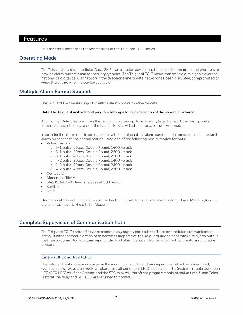
Features
This section summarizes the key features of the Telguard TG-7 series.
Operating Mode
The Telguard is a digital cellular Data/SMS transmission device that is installed at the protected premises to provide alarm transmission for security systems. The Telguard TG-7 series transmits alarm signals over the nationwide digital cellular network if the telephone line or data network has been disrupted, compromised or when there is no wire line service available.
Multiple Alarm Format Support
The Telguard TG-7 series supports multiple alarm communication formats.
Note: The Telguard unit’s default program setting is for auto detection of the panel alarm format.
Auto Format Detect feature allows the Telguard unit to adapt to receive any listed format. If the alarm panel’s format is changed for any reason, the Telguard device will adjust to accept the new format.
In order for the alarm panel to be compatible with the Telguard, the alarm panel must be programmed to transmit alarm messages to the central station using one of the following non-extended formats: • Pulse Formats:
o 3+1 pulse; 10pps, Double Round, 1400 Hz ack o 3+1 pulse; 20pps, Double Round, 2300 Hz ack o 3+1 pulse; 40pps, Double Round, 2300 Hz ack o 4+2 pulse; 20pps, Double Round, 1400 Hz ack o 4+2 pulse; 20pps, Double Round, 2300 Hz ack o 4+2 pulse; 40pps, Double Round, 2300 Hz ack
• Contact ID • Modem IIe/IIIa2/4 • SIA2 (SIA-DC-03 level 2 release at 300 baud) • Sonitrol • DMP
Hexadecimal account numbers can be used with 3+1 or 4+2 formats, as well as Contact ID and Modem (4 or 10 digits for Contact ID, 4 digits for Modem).
Complete Supervision of Communication Path
The Telguard TG-7 series of devices continuously supervises both the Telco and cellular communication paths. If either communication path becomes inoperative, the Telguard device generates a relay trip output that can be connected to a zone input of the host alarm panel and/or used to control remote annunciation devices.
Line Fault Condition (LFC)
The Telguard unit monitors voltage on the incoming Telco line. If an inoperative Telco line is identified, (voltage below –20vdc, on hook) a Telco line fault condition (LFC) is declared. The System Trouble Condition LED (STC LED) will flash 3 times and the STC relay will trip after a programmable period of time. Upon Telco restoral, the relay and STC LED are returned to normal.
LS10265-000HW-E:C 04/27/2021 4 56052901 – Rev B
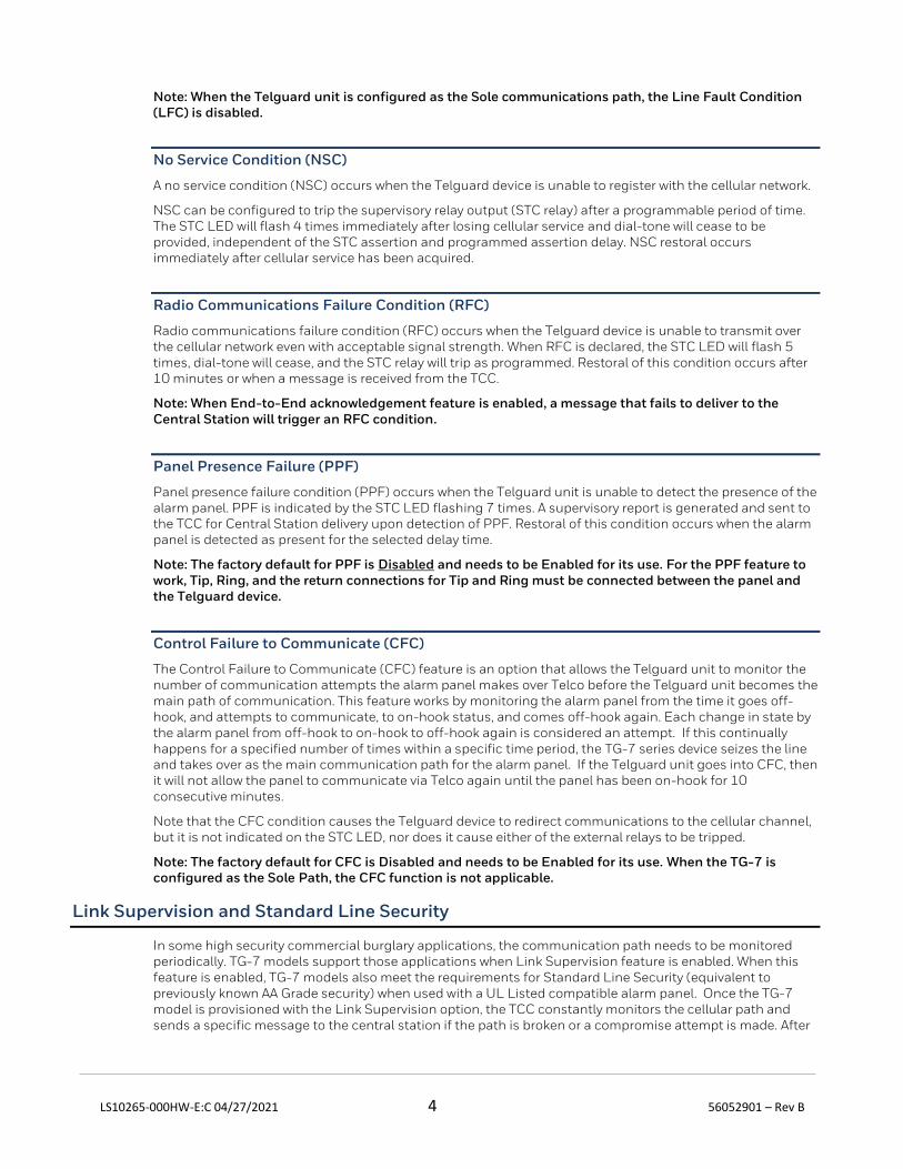
Note: When the Telguard unit is configured as the Sole communications path, the Line Fault Condition (LFC) is disabled.
No Service Condition (NSC)
A no service condition (NSC) occurs when the Telguard device is unable to register with the cellular network.
NSC can be configured to trip the supervisory relay output (STC relay) after a programmable period of time. The STC LED will flash 4 times immediately after losing cellular service and dial-tone will cease to be provided, independent of the STC assertion and programmed assertion delay. NSC restoral occurs immediately after cellular service has been acquired.
Radio Communications Failure Condition (RFC)
Radio communications failure condition (RFC) occurs when the Telguard device is unable to transmit over the cellular network even with acceptable signal strength. When RFC is declared, the STC LED will flash 5 times, dial-tone will cease, and the STC relay will trip as programmed. Restoral of this condition occurs after 10 minutes or when a message is received from the TCC.
Note: When End-to-End acknowledgement feature is enabled, a message that fails to deliver to the Central Station will trigger an RFC condition.
Panel Presence Failure (PPF)
Panel presence failure condition (PPF) occurs when the Telguard unit is unable to detect the presence of the alarm panel. PPF is indicated by the STC LED flashing 7 times. A supervisory report is generated and sent to the TCC for Central Station delivery upon detection of PPF. Restoral of this condition occurs when the alarm panel is detected as present for the selected delay time.
Note: The factory default for PPF is Disabled and needs to be Enabled for its use. For the PPF feature to work, Tip, Ring, and the return connections for Tip and Ring must be connected between the panel and the Telguard device.
Control Failure to Communicate (CFC)
The Control Failure to Communicate (CFC) feature is an option that allows the Telguard unit to monitor the number of communication attempts the alarm panel makes over Telco before the Telguard unit becomes the main path of communication. This feature works by monitoring the alarm panel from the time it goes off-hook, and attempts to communicate, to on-hook status, and comes off-hook again. Each change in state by the alarm panel from off-hook to on-hook to off-hook again is considered an attempt. If this continually happens for a specified number of times within a specific time period, the TG-7 series device seizes the line and takes over as the main communication path for the alarm panel. If the Telguard unit goes into CFC, then it will not allow the panel to communicate via Telco again until the panel has been on-hook for 10 consecutive minutes.
Note that the CFC condition causes the Telguard device to redirect communications to the cellular channel, but it is not indicated on the STC LED, nor does it cause either of the external relays to be tripped.
Note: The factory default for CFC is Disabled and needs to be Enabled for its use. When the TG-7 is configured as the Sole Path, the CFC function is not applicable.
Link Supervision and Standard Line Security
In some high security commercial burglary applications, the communication path needs to be monitored periodically. TG-7 models support those applications when Link Supervision feature is enabled. When this feature is enabled, TG-7 models also meet the requirements for Standard Line Security (equivalent to previously known AA Grade security) when used with a UL Listed compatible alarm panel. Once the TG-7 model is provisioned with the Link Supervision option, the TCC constantly monitors the cellular path and sends a specific message to the central station if the path is broken or a compromise attempt is made. After
LS10265-000HW-E:C 04/27/2021 5 56052901 – Rev B
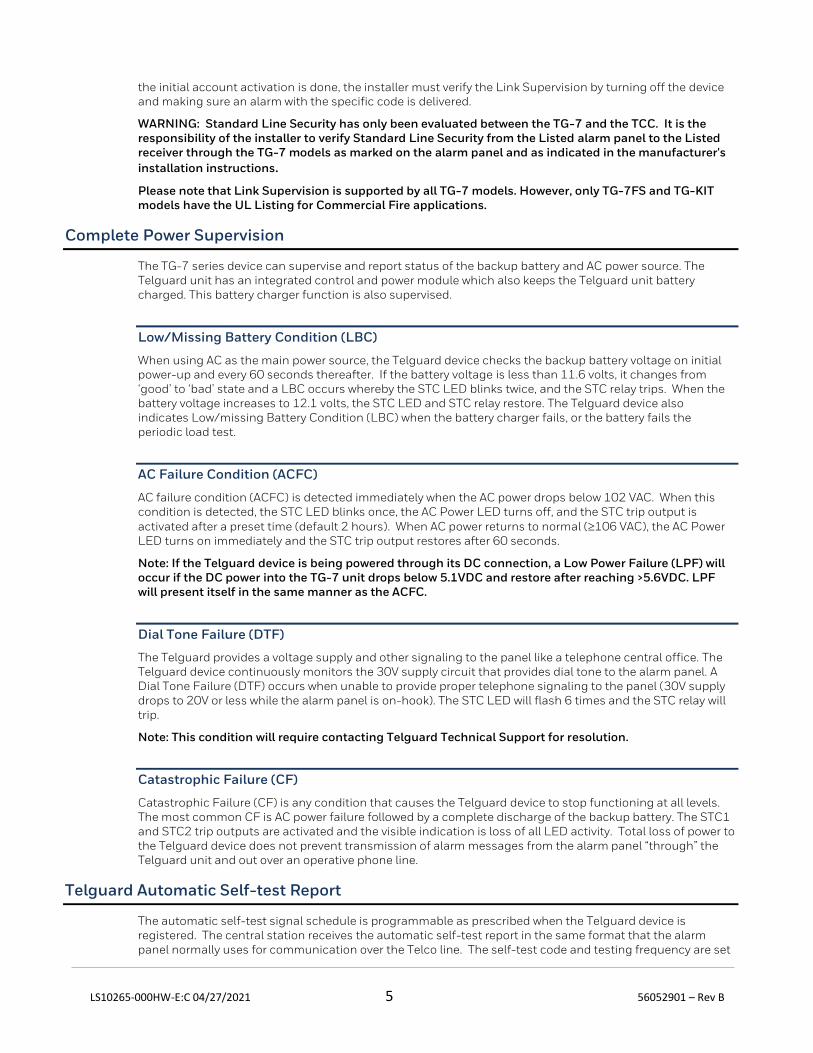
the initial account activation is done, the installer must verify the Link Supervision by turning off the device and making sure an alarm with the specific code is delivered.
WARNING: Standard Line Security has only been evaluated between the TG-7 and the TCC. It is the responsibility of the installer to verify Standard Line Security from the Listed alarm panel to the Listed receiver through the TG-7 models as marked on the alarm panel and as indicated in the manufacturer's
installation instructions.
Please note that Link Supervision is supported by all TG-7 models. However, only TG-7FS and TG-KIT models have the UL Listing for Commercial Fire applications.
Complete Power Supervision
The TG-7 series device can supervise and report status of the backup battery and AC power source. The Telguard unit has an integrated control and power module which also keeps the Telguard unit battery charged. This battery charger function is also supervised.
Low/Missing Battery Condition (LBC)
When using AC as the main power source, the Telguard device checks the backup battery voltage on initial power-up and every 60 seconds thereafter. If the battery voltage is less than 11.6 volts, it changes from ‘good’ to ‘bad’ state and a LBC occurs whereby the STC LED blinks twice, and the STC relay trips. When the battery voltage increases to 12.1 volts, the STC LED and STC relay restore. The Telguard device also indicates Low/missing Battery Condition (LBC) when the battery charger fails, or the battery fails the periodic load test.
AC Failure Condition (ACFC)
AC failure condition (ACFC) is detected immediately when the AC power drops below 102 VAC. When this condition is detected, the STC LED blinks once, the AC Power LED turns off, and the STC trip output is activated after a preset time (default 2 hours). When AC power returns to normal (106 VAC), the AC Power LED turns on immediately and the STC trip output restores after 60 seconds.
Note: If the Telguard device is being powered through its DC connection, a Low Power Failure (LPF) will occur if the DC power into the TG-7 unit drops below 5.1VDC and restore after reaching >5.6VDC. LPF will present itself in the same manner as the ACFC.
Dial Tone Failure (DTF)
The Telguard provides a voltage supply and other signaling to the panel like a telephone central office. The Telguard device continuously monitors the 30V supply circuit that provides dial tone to the alarm panel. A Dial Tone Failure (DTF) occurs when unable to provide proper telephone signaling to the panel (30V supply drops to 20V or less while the alarm panel is on-hook). The STC LED will flash 6 times and the STC relay will trip.
Note: This condition will require contacting Telguard Technical Support for resolution.
Catastrophic Failure (CF)
Catastrophic Failure (CF) is any condition that causes the Telguard device to stop functioning at all levels. The most common CF is AC power failure followed by a complete discharge of the backup battery. The STC1 and STC2 trip outputs are activated and the visible indication is loss of all LED activity. Total loss of power to the Telguard device does not prevent transmission of alarm messages from the alarm panel “through” the Telguard unit and out over an operative phone line.
Telguard Automatic Self-test Report
The automatic self-test signal schedule is programmable as prescribed when the Telguard device is registered. The central station receives the automatic self-test report in the same format that the alarm panel normally uses for communication over the Telco line. The self-test code and testing frequency are set
LS10265-000HW-E:C 04/27/2021 6 56052901 – Rev B
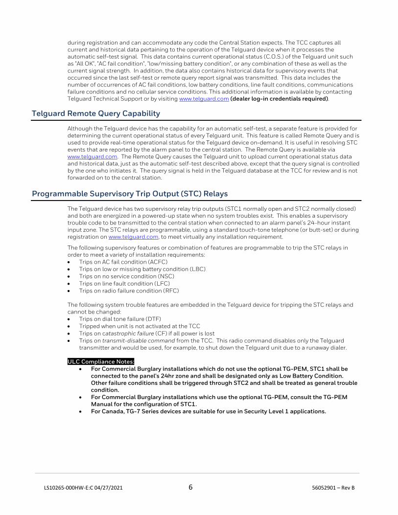
during registration and can accommodate any code the Central Station expects. The TCC captures all current and historical data pertaining to the operation of the Telguard device when it processes the automatic self-test signal. This data contains current operational status (C.O.S.) of the Telguard unit such as "All OK", "AC fail condition", "low/missing battery condition", or any combination of these as well as the current signal strength. In addition, the data also contains historical data for supervisory events that occurred since the last self-test or remote query report signal was transmitted. This data includes the number of occurrences of AC fail conditions, low battery conditions, line fault conditions, communications failure conditions and no cellular service conditions. This additional information is available by contacting Telguard Technical Support or by visiting www.telguard.com (dealer log-in credentials required).
Telguard Remote Query Capability
Although the Telguard device has the capability for an automatic self-test, a separate feature is provided for determining the current operational status of every Telguard unit. This feature is called Remote Query and is used to provide real-time operational status for the Telguard device on-demand. It is useful in resolving STC events that are reported by the alarm panel to the central station. The Remote Query is available via www.telguard.com. The Remote Query causes the Telguard unit to upload current operational status data and historical data, just as the automatic self-test described above, except that the query signal is controlled by the one who initiates it. The query signal is held in the Telguard database at the TCC for review and is not forwarded on to the central station.
Programmable Supervisory Trip Output (STC) Relays
The Telguard device has two supervisory relay trip outputs (STC1 normally open and STC2 normally closed) and both are energized in a powered-up state when no system troubles exist. This enables a supervisory trouble code to be transmitted to the central station when connected to an alarm panel’s 24-hour instant input zone. The STC relays are programmable, using a standard touch-tone telephone (or butt-set) or during registration on www.telguard.com, to meet virtually any installation requirement.
The following supervisory features or combination of features are programmable to trip the STC relays in order to meet a variety of installation requirements: • Trips on AC fail condition (ACFC) • Trips on low or missing battery condition (LBC) • Trips on no service condition (NSC) • Trips on line fault condition (LFC) • Trips on radio failure condition (RFC)
The following system trouble features are embedded in the Telguard device for tripping the STC relays and cannot be changed: • Trips on dial tone failure (DTF) • Tripped when unit is not activated at the TCC • Trips on catastrophic failure (CF) if all power is lost • Trips on transmit-disable command from the TCC. This radio command disables only the Telguard
transmitter and would be used, for example, to shut down the Telguard unit due to a runaway dialer.
ULC Compliance Notes: • For Commercial Burglary installations which do not use the optional TG-PEM, STC1 shall be
connected to the panel's 24hr zone and shall be designated only as Low Battery Condition. Other failure conditions shall be triggered through STC2 and shall be treated as general trouble condition.
• For Commercial Burglary installations which use the optional TG-PEM, consult the TG-PEM Manual for the configuration of STC1.
• For Canada, TG-7 Series devices are suitable for use in Security Level 1 applications.
LS10265-000HW-E:C 04/27/2021 7 56052901 – Rev B
Post-Installation Remote Programming (Commercial Fire Applications and All
Applications in Canada)
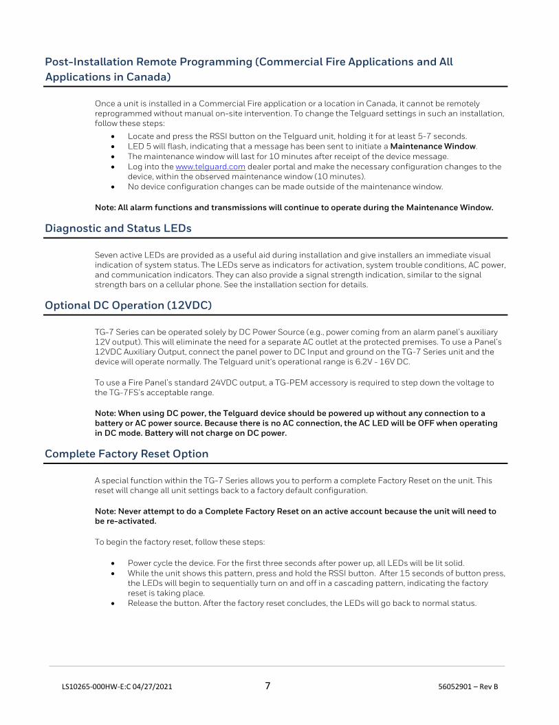
Once a unit is installed in a Commercial Fire application or a location in Canada, it cannot be remotely reprogrammed without manual on-site intervention. To change the Telguard settings in such an installation, follow these steps:
• Locate and press the RSSI button on the Telguard unit, holding it for at least 5-7 seconds. • LED 5 will flash, indicating that a message has been sent to initiate a Maintenance Window. • The maintenance window will last for 10 minutes after receipt of the device message. • Log into the www.telguard.com dealer portal and make the necessary configuration changes to the
device, within the observed maintenance window (10 minutes). • No device configuration changes can be made outside of the maintenance window.
Note: All alarm functions and transmissions will continue to operate during the Maintenance Window.
Diagnostic and Status LEDs
Seven active LEDs are provided as a useful aid during installation and give installers an immediate visual indication of system status. The LEDs serve as indicators for activation, system trouble conditions, AC power, and communication indicators. They can also provide a signal strength indication, similar to the signal strength bars on a cellular phone. See the installation section for details.
Optional DC Operation (12VDC)
TG-7 Series can be operated solely by DC Power Source (e.g., power coming from an alarm panel’s auxiliary 12V output). This will eliminate the need for a separate AC outlet at the protected premises. To use a Panel’s 12VDC Auxiliary Output, connect the panel power to DC Input and ground on the TG-7 Series unit and the device will operate normally. The Telguard unit‘s operational range is 6.2V - 16V DC.
To use a Fire Panel’s standard 24VDC output, a TG-PEM accessory is required to step down the voltage to the TG-7FS’s acceptable range.
Note: When using DC power, the Telguard device should be powered up without any connection to a battery or AC power source. Because there is no AC connection, the AC LED will be OFF when operating in DC mode. Battery will not charge on DC power.
Complete Factory Reset Option
A special function within the TG-7 Series allows you to perform a complete Factory Reset on the unit. This reset will change all unit settings back to a factory default configuration.
Note: Never attempt to do a Complete Factory Reset on an active account because the unit will need to be re-activated.
To begin the factory reset, follow these steps:
• Power cycle the device. For the first three seconds after power up, all LEDs will be lit solid. • While the unit shows this pattern, press and hold the RSSI button. After 15 seconds of button press,
the LEDs will begin to sequentially turn on and off in a cascading pattern, indicating the factory reset is taking place.
• Release the button. After the factory reset concludes, the LEDs will go back to normal status.
LS10265-000HW-E:C 04/27/2021 8 56052901 – Rev B
UL and ULC Compliance
The TG-7 series includes models that are certified as complying with UL and ULC Standards for all Household Burglary, Household Fire, Commercial Burglary, and Commercial Fire installations. The chart on Page 2 shows the various models and the associated UL and ULC Standards. Certificates of Compliance are available at www.telguard.com.
UL/ULC Compliance Note: The alarm panel must also be UL, ULC, or cUL Listed for the appropriate categories above.
ULC Compliance Note: For Commercial Fire installations in Canada, the radio frequency warning label (supplied) must be affixed to the outside front cover of the TG-7 device to maintain compliance.
LS10265-000HW-E:C 04/27/2021 9 56052901 – Rev B
Getting Ready
The Telguard device can only be activated when all necessary accounting information has been added to the customer database located at the TCC (i.e., the unit has been registered). The database includes information about the customer account, unit location, and system test plan information.
Dealer Account Establishment
A Dealer Account must be established prior to registration of any Telguard unit. This can be accomplished by visiting www.telguard.com and completing the necessary information under “Dealer Signup”. This is a one-time event and an acknowledgment from Telguard Customer Service will include a Dealer Account Number that will be used for all Telguard Digital registrations. Telguard units can be registered and activated once the Dealer Account has been established.
Pre-Installation Checklist
Before attempting to connect the Telguard device to the alarm panel, please make sure you have all the proper parts before you go to the job site. The following items are shipped with each Telguard unit:
• Telguard Cellular Communicator • UL Listed plug-in transformer • Cellular Antenna • 12-foot antenna cable with mounting bracket • 7-foot RJ 45 plug-to-plug cord • 20-inch battery cable assembly with connector plug • Enclosure key lock • Pluggable screw terminal blocks (2, 3 & 6 position) • Quick Install Guide • Registration Form • Tamper switch (applicable to TG-7 units sold in Canada)
Note: The Telguard device registration must be completed in advance to avoid installation delays
You must also have certain installation test tools:
• Screws and a screwdriver will be required to attach the Telguard unit and antenna to the wall. • To connect the STC relay outputs and trip input to the alarm panel, solid or stranded electrical wire will
be required. The terminal strips can accommodate solid or stranded wire from 14 to 22 gauge in size. • A standard telephone or lineman's butt-set is recommended for verifying communication between the
panel and the Telguard unit.

LS10265-000HW-E:C 04/27/2021 10 56052901 – Rev B
Installation
Summary
The following are steps necessary to install the Telguard device properly.
NOTE: IF YOU DO NOT PROCEED IN THE ORDER AND MANNER PRESCRIBED, YOU MAY NOT COMPLETE THE INSTALLATION IN THE TIME DESIRED.
These steps are summarized below and explained in detail in the remainder of this manual. 1. Register for Telguard service 2. Physically install the TG-7 Series device
• Mount the TG-7 Series device in desired location • If using the optional TG-PEM accessory, install it according to its directions • Complete all power-related wiring connections
3. Determine antenna placement for best performance • Connect antenna • Measure Received Signal Strength (RSSI) • Consider other antenna options
4. Transmit an alarm over the Telco connection 5. Activate and transmit alarm panel alarm messages over cellular connection 6. Connect supervisory trip outputs 7. Connect trip input (optional) 8. Connect Tamper Switch (optional)
Note: Step 4 not necessary for Sole Path installations.
This installation approach provides the alarm installer with the easiest and fastest method of properly installing a TG-7 Series device. Please follow the instructions carefully and if you should need assistance or have any questions, please call Telguard Technical Support at 1-800-229-2326 extension 9.
Note: Dealer Account Establishment and Telguard Registration must be complete prior to Installation.
Step 1: Register the Telguard Unit
Installation Tip: Register for Telguard service prior to leaving for the job site to avoid a second trip.
The registration form may be completed online through our 24/7 dealer portal www.telguard.com.
The desired features and programmable options for any installation are selected during the registration process. This includes STC strategy, Trip-Input enabling, and added value services like HomeControl Flex and Standard Line Security.
UL/ULC Commercial Fire Sole Path Features
• Link Supervision: When registering a TG-7FS or TG-KIT device for commercial fire applications, several link supervision options are available per UL (5-minute supervision and 60-minute supervision) and ULC (180-second supervision) requirements. These must be enabled during registration in accordance to code.
• End-to-End Acknowledgment feature: When enabled an RFC condition will occur when the captured signal is not delivered to the Central Station as expected.
Decide on a STC Trip Output Strategy
The Telguard device provides the host alarm panel with two supervisory trip outputs for reporting a Telguard system trouble code to the central station. The supervisory trip outputs are programmable to suit various
LS10265-000HW-E:C 04/27/2021 11 56052901 – Rev B
installation requirements. The programming options for these supervisory trip outputs can be any combination of the following:
• Always Off: Disables all relay supervisory functions. • ACFC: Trips 2 hours (programmable for up to 24 hours) after loss of AC power. Restores 60 seconds
after AC power is restored. • LBC: Trips within 60 seconds on low battery condition. Restores when battery voltage 12.1 vdc. • LFC: Trips after 60 seconds on Telco line fault condition (delay is programmable). Restores 60
seconds after Telco line restores. • NSC: Trips after a 60 second delay (delay is programmable) on no service condition due to loss of
RF signal strength. Restores after RF signal strength is available. • RFC: Trips on radio failure to communicate with the TCC. Restores after 10 minutes.
Note: When the TG-PEM is used, it can be configured to use STC1. This TG-PEM configuration will limit Telguard supervisory trip output options to STC2 only.
Optional Trip Input
When the input is tripped, a supervisory message is sent to the central station via the TCC. This allows an external relay, separate from the alarm panel, to be connected to the Telguard unit in order to provide independent sensor input for other functions, such as tamper detection.
The message that is sent from the TCC to the central station is configurable in Telguard Online. The TG-7 series unit will automatically be configured with a unit template that allows configuration of the trip input feature, including the message that is sent to the central station. There is a default event configured for each alarm format, so that if the unit is configured with the butt-set to send trip input events to the TCC, a default notification will be sent to the central station. If the Telguard unit is configured to report restorals, the contact closure will also be reported.
Swinger Function
The swinger function is designed to reduce the incidence of excessive messaging and alarms due to faulty equipment or installation. If enabled, the swinger function will discontinue sending trip input messages to the TCC once 10 trip events are detected within a 10-minute period. The Telguard device will resume sending trip input messages to the TCC after a 10-minute period without trip events.
Step 2: Physically Install the TG-7 Series Device in Desired Location
Identify Location for Placing the TG-7 Series Device and Mount
Do not install the Telguard device in an area where the general public could reasonably be within 20cm (8 inches) of the antenna.
NOTE 1: Optimum RF performance can usually be found at the highest point within a building with the fewest number of walls between the Telguard unit’s antenna and the outside of the premises.
NOTE 2: To avoid interference with other electronic devices operating in the area, avoid mounting the Telguard unit’s antenna near other electronic devices.
NOTE 3: The Telguard unit’s dipole antenna is designed for indoor installations only.
Care should be taken to ensure that a large metal object such as a refrigerator or a metal cabinet is not located on the opposite side of the wall. If moving the Telguard unit to a different location is not practical, you may need to get an extension cable and remote the antenna in order to receive adequate radio signal strength. Choose a high, visually secure spot using the guidelines below.
Tips for Improved Radio Signal Reception
• The higher the antenna the better. Start in the drop ceiling above the unit and proceed from there, up to the roof if necessary.
LS10265-000HW-E:C 04/27/2021 12 56052901 – Rev B
• Remember, the antenna should be as inconspicuous as possible for greatest visual security. • Try to keep the antenna away from sources of RF interference, including pumps, compressors, ovens,
etc., or where metal objects can shield it or otherwise block the cellular radio RF signal.
Place the antenna perpendicular to the ground, pointing either straight up or down. Do not mount the antenna horizontally. Mount the Telguard unit to the wall or other surface near the alarm panel. Care should be taken to avoid equipment that may make receiving a clear cellular signal difficult.
• Attach earth ground to the grounding screw located on lower right-hand corner of printed circuit board
assembly and permanently mount the Telguard enclosure.
• Install mounting screws.
• Slide the enclosure onto these screws.
• Verify unit is secured by tightening screws and/or by placing additional screws in lower mounting holes.
Install Optional TG-PEM Accessory into TG-7 or TG-7FS (if using)
The TG-PEM Power and Expansion Module can be used to convert 24VDC fire panel power to the necessary voltage to operate the TG-7FS. It can also be used to add 8 24-hour dry contact zones (16 with two TG-PEM units) to a TG-7.
The TG-PEM should be installed after the TG-7 series device has been mounted to the wall or other surface. Follow the instructions for the TG-PEM to install it. After installation of the TG-PEM, proceed to Option 2 in the next section.
Note: When the TG-PEM is used to provide power, the TG-7 series device cannot have an AC power transformer or backup battery connected.
Complete all Power-Related Wiring Connections
Option 1: Backup Battery and AC Power Transformer
To apply power to the Telguard, attach a battery to the battery connector jack using the supplied battery cable. If the need for a different size cable arises, the Telguard provides an alternate screw-in terminal connection for the battery. Backup battery must be sized appropriately to meet installation requirements.
Connect the Telguard AC power transformer (see A6 for acceptable UL Listed transformers) to AC terminals using stranded copper insulated wire following wire gauge and length recommendations below:
Recommended Wire Size Length Not to Exceed 18 ga 20 ft 16 ga 40 ft 14 ga 60 ft
Option 2: DC Power
When using this option, no other power connections (battery or AC) should be wired.
Power to the TG-7 series device may be sourced from the host alarm panel 12VDC auxiliary output. Connect the power and ground connections into the respective DC and GND connections on the TG-7 Series using the 2-position terminal block provided.
Note: If alarm panel output voltage is higher (e.g., 24VDC), the TG-PEM accessory is required.
LS10265-000HW-E:C 04/27/2021 13 56052901 – Rev B
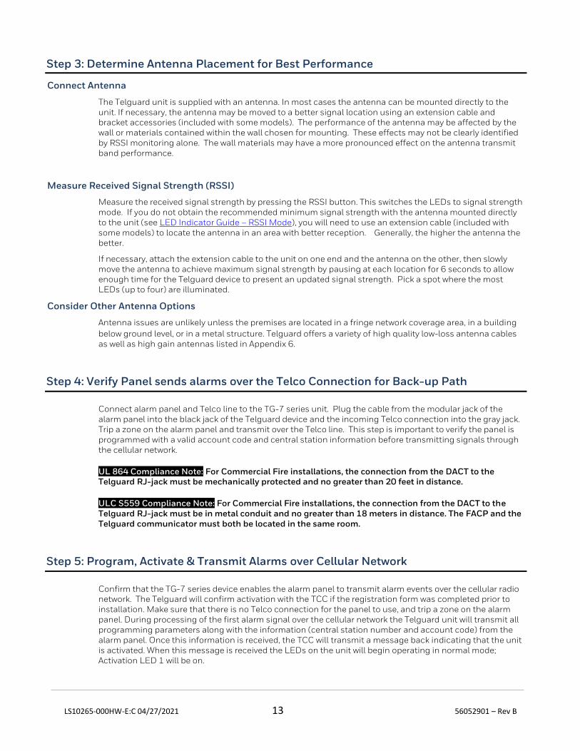
Step 3: Determine Antenna Placement for Best Performance
Connect Antenna
The Telguard unit is supplied with an antenna. In most cases the antenna can be mounted directly to the unit. If necessary, the antenna may be moved to a better signal location using an extension cable and bracket accessories (included with some models). The performance of the antenna may be affected by the wall or materials contained within the wall chosen for mounting. These effects may not be clearly identified by RSSI monitoring alone. The wall materials may have a more pronounced effect on the antenna transmit band performance.
Measure Received Signal Strength (RSSI)
Measure the received signal strength by pressing the RSSI button. This switches the LEDs to signal strength mode. If you do not obtain the recommended minimum signal strength with the antenna mounted directly to the unit (see LED Indicator Guide – RSSI Mode), you will need to use an extension cable (included with some models) to locate the antenna in an area with better reception. Generally, the higher the antenna the better.
If necessary, attach the extension cable to the unit on one end and the antenna on the other, then slowly move the antenna to achieve maximum signal strength by pausing at each location for 6 seconds to allow enough time for the Telguard device to present an updated signal strength. Pick a spot where the most LEDs (up to four) are illuminated.
Consider Other Antenna Options
Antenna issues are unlikely unless the premises are located in a fringe network coverage area, in a building
below ground level, or in a metal structure. Telguard offers a variety of high quality low-loss antenna cables as well as high gain antennas listed in Appendix 6.
Step 4: Verify Panel sends alarms over the Telco Connection for Back-up Path
Connect alarm panel and Telco line to the TG-7 series unit. Plug the cable from the modular jack of the alarm panel into the black jack of the Telguard device and the incoming Telco connection into the gray jack. Trip a zone on the alarm panel and transmit over the Telco line. This step is important to verify the panel is programmed with a valid account code and central station information before transmitting signals through the cellular network.
UL 864 Compliance Note: For Commercial Fire installations, the connection from the DACT to the Telguard RJ-jack must be mechanically protected and no greater than 20 feet in distance.
ULC S559 Compliance Note: For Commercial Fire installations, the connection from the DACT to the Telguard RJ-jack must be in metal conduit and no greater than 18 meters in distance. The FACP and the Telguard communicator must both be located in the same room.
Step 5: Program, Activate & Transmit Alarms over Cellular Network
Confirm that the TG-7 series device enables the alarm panel to transmit alarm events over the cellular radio network. The Telguard will confirm activation with the TCC if the registration form was completed prior to installation. Make sure that there is no Telco connection for the panel to use, and trip a zone on the alarm panel. During processing of the first alarm signal over the cellular network the Telguard unit will transmit all programming parameters along with the information (central station number and account code) from the alarm panel. Once this information is received, the TCC will transmit a message back indicating that the unit is activated. When this message is received the LEDs on the unit will begin operating in normal mode; Activation LED 1 will be on.
LS10265-000HW-E:C 04/27/2021 14 56052901 – Rev B
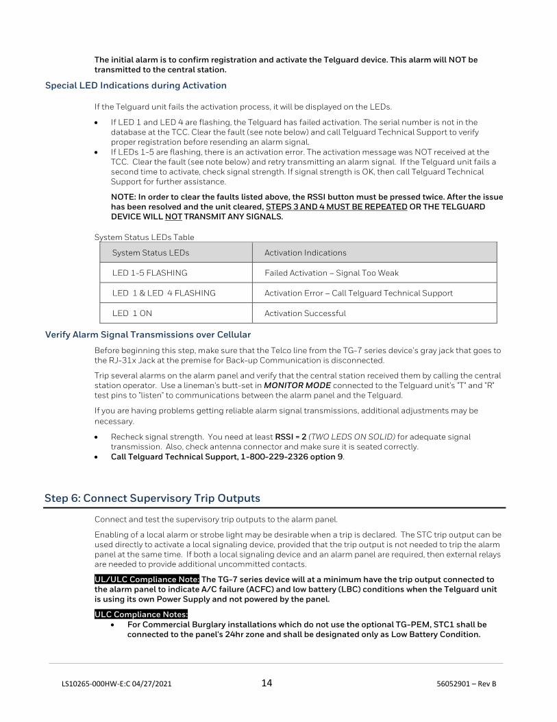
The initial alarm is to confirm registration and activate the Telguard device. This alarm will NOT be transmitted to the central station.
Special LED Indications during Activation
If the Telguard unit fails the activation process, it will be displayed on the LEDs.
• If LED 1 and LED 4 are flashing, the Telguard has failed activation. The serial number is not in the database at the TCC. Clear the fault (see note below) and call Telguard Technical Support to verify proper registration before resending an alarm signal.
• If LEDs 1-5 are flashing, there is an activation error. The activation message was NOT received at the TCC. Clear the fault (see note below) and retry transmitting an alarm signal. If the Telguard unit fails a second time to activate, check signal strength. If signal strength is OK, then call Telguard Technical Support for further assistance.
NOTE: In order to clear the faults listed above, the RSSI button must be pressed twice. After the issue has been resolved and the unit cleared, STEPS 3 AND 4 MUST BE REPEATED OR THE TELGUARD DEVICE WILL NOT TRANSMIT ANY SIGNALS.
System Status LEDs Table
System Status LEDs Activation Indications
LED 1-5 FLASHING Failed Activation – Signal Too Weak
LED 1 & LED 4 FLASHING Activation Error – Call Telguard Technical Support
LED 1 ON Activation Successful
Verify Alarm Signal Transmissions over Cellular
Before beginning this step, make sure that the Telco line from the TG-7 series device’s gray jack that goes to the RJ-31x Jack at the premise for Back-up Communication is disconnected.
Trip several alarms on the alarm panel and verify that the central station received them by calling the central station operator. Use a lineman's butt-set in MONITOR MODE connected to the Telguard unit's "T" and "R" test pins to "listen" to communications between the alarm panel and the Telguard.
If you are having problems getting reliable alarm signal transmissions, additional adjustments may be
necessary.
• Recheck signal strength. You need at least RSSI = 2 (TWO LEDS ON SOLID) for adequate signal transmission. Also, check antenna connector and make sure it is seated correctly.
• Call Telguard Technical Support, 1-800-229-2326 option 9.
Step 6: Connect Supervisory Trip Outputs
Connect and test the supervisory trip outputs to the alarm panel.
Enabling of a local alarm or strobe light may be desirable when a trip is declared. The STC trip output can be used directly to activate a local signaling device, provided that the trip output is not needed to trip the alarm panel at the same time. If both a local signaling device and an alarm panel are required, then external relays are needed to provide additional uncommitted contacts.
UL/ULC Compliance Note: The TG-7 series device will at a minimum have the trip output connected to the alarm panel to indicate A/C failure (ACFC) and low battery (LBC) conditions when the Telguard unit is using its own Power Supply and not powered by the panel.
ULC Compliance Notes: • For Commercial Burglary installations which do not use the optional TG-PEM, STC1 shall be
connected to the panel's 24hr zone and shall be designated only as Low Battery Condition.
LS10265-000HW-E:C 04/27/2021 15 56052901 – Rev B
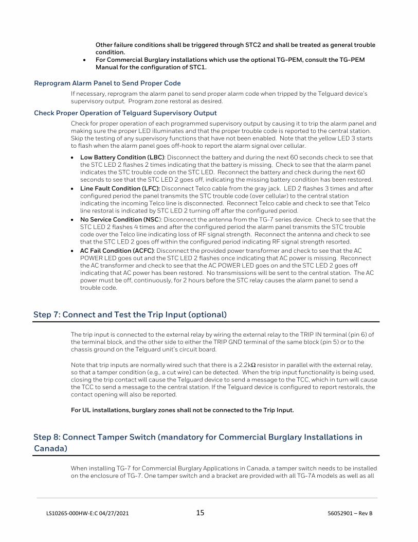
Other failure conditions shall be triggered through STC2 and shall be treated as general trouble condition.
• For Commercial Burglary installations which use the optional TG-PEM, consult the TG-PEM Manual for the configuration of STC1.
Reprogram Alarm Panel to Send Proper Code
If necessary, reprogram the alarm panel to send proper alarm code when tripped by the Telguard device’s supervisory output. Program zone restoral as desired.
Check Proper Operation of Telguard Supervisory Output
Check for proper operation of each programmed supervisory output by causing it to trip the alarm panel and making sure the proper LED illuminates and that the proper trouble code is reported to the central station. Skip the testing of any supervisory functions that have not been enabled. Note that the yellow LED 3 starts to flash when the alarm panel goes off-hook to report the alarm signal over cellular.
• Low Battery Condition (LBC): Disconnect the battery and during the next 60 seconds check to see that the STC LED 2 flashes 2 times indicating that the battery is missing. Check to see that the alarm panel indicates the STC trouble code on the STC LED. Reconnect the battery and check during the next 60 seconds to see that the STC LED 2 goes off, indicating the missing battery condition has been restored.
• Line Fault Condition (LFC): Disconnect Telco cable from the gray jack. LED 2 flashes 3 times and after configured period the panel transmits the STC trouble code (over cellular) to the central station indicating the incoming Telco line is disconnected. Reconnect Telco cable and check to see that Telco line restoral is indicated by STC LED 2 turning off after the configured period.
• No Service Condition (NSC): Disconnect the antenna from the TG-7 series device. Check to see that the STC LED 2 flashes 4 times and after the configured period the alarm panel transmits the STC trouble code over the Telco line indicating loss of RF signal strength. Reconnect the antenna and check to see that the STC LED 2 goes off within the configured period indicating RF signal strength resorted.
• AC Fail Condition (ACFC): Disconnect the provided power transformer and check to see that the AC POWER LED goes out and the STC LED 2 flashes once indicating that AC power is missing. Reconnect the AC transformer and check to see that the AC POWER LED goes on and the STC LED 2 goes off indicating that AC power has been restored. No transmissions will be sent to the central station. The AC power must be off, continuously, for 2 hours before the STC relay causes the alarm panel to send a trouble code.
Step 7: Connect and Test the Trip Input (optional)
The trip input is connected to the external relay by wiring the external relay to the TRIP IN terminal (pin 6) of the terminal block, and the other side to either the TRIP GND terminal of the same block (pin 5) or to the chassis ground on the Telguard unit’s circuit board.
Note that trip inputs are normally wired such that there is a 2.2kΩ resistor in parallel with the external relay, so that a tamper condition (e.g., a cut wire) can be detected. When the trip input functionality is being used, closing the trip contact will cause the Telguard device to send a message to the TCC, which in turn will cause the TCC to send a message to the central station. If the Telguard device is configured to report restorals, the contact opening will also be reported.
For UL installations, burglary zones shall not be connected to the Trip Input.
Step 8: Connect Tamper Switch (mandatory for Commercial Burglary Installations in
Canada)
When installing TG-7 for Commercial Burglary Applications in Canada, a tamper switch needs to be installed on the enclosure of TG-7. One tamper switch and a bracket are provided with all TG-7A models as well as all

LS10265-000HW-E:C 04/27/2021 16 56052901 – Rev B
TG-7 burglary models sold in Canada. The tamper switch needs to be connected to a zone on the panel and shall designate the zone as Tamper Protection. All Canadian Installations shall also meet the installation requirements of CAN/ULC-S302 standard for Installation and Classification of Burglar Alarm Systems for Financial and Commercial Premises, Safes and Vaults. For installations outside Canada, a tamper switch may be used if desired (not supplied) or as required by local AHJ.
LS10265-000HW-E:C 04/27/2021 17 56052901 – Rev B
Appendix 1 – Connection Guide
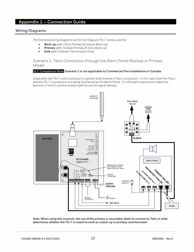
Wiring Diagrams
The following wiring diagrams are for the Telguard TG-7 series used for:
• Back-up path (Telco Primary & Cellular Back-up) • Primary path (Cellular Primary & Telco Back-up) • Sole path (Cellular Transmission Only)
Scenario 1: Telco Connection through the Alarm Panel (Backup or Primary Mode)
ULC Compliance Note: Scenario 1 is not applicable to Commercial Fire installations in Canada.
Used when the TG-7 unit is working in a system that involves a Telco connection. In this case, both the Telco and the TG-7 connections are being monitored by the Alarm Panel. It is the alarm panel that makes the decision of which communication path to use for signal delivery.
REMOTE
ANTENNA
T
R
TELGUARD
Digital TG-7
SIM
12345678
Not Used
Not Used
Power LED
LED ModeToggle Button
System Status LEDs
Alarm Panel
Battery Connector
Battery wire should be at least ¼ inch apart from AC wires
2
34 5
7
GR
EE
N
R
1
T
RE
D
INCOMINGTELCO
RJ31X
TRIP INPUT
BATTERY
TAMPER
SWITCH
8
6
Note
EARTHGROUND
STC2(N.C.)
AC(12V 800MA)
STC1(N.O.)
1 2 3 5 6 1 21 2 1 324
Battery Connector
+-
Note: When using this scenario, the use of the primary or secondary dialer to connect to Telco is what determines whether the TG-7 is meant to work as a back-up or primary communicator.

LS10265-000HW-E:C 04/27/2021 18 56052901 – Rev B
Note 2: When using this scenario, LFC and CFC do not apply.
LS10265-000HW-E:C 04/27/2021 19 56052901 – Rev B
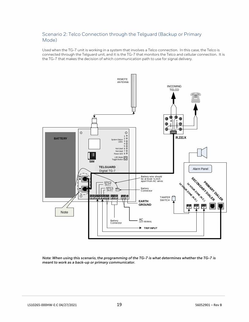
Scenario 2: Telco Connection through the Telguard (Backup or Primary Mode)
Used when the TG-7 unit is working in a system that involves a Telco connection. In this case, the Telco is connected through the Telguard unit, and it is the TG-7 that monitors the Telco and cellular connection. It is the TG-7 that makes the decision of which communication path to use for signal delivery.
REMOTE
ANTENNA
T
R
TELGUARD
Digital TG-7
SIM
12345678
Not Used
Not Used
Power LED
LED ModeToggle Button
System Status LEDs
Alarm Panel
Battery wire should be at least ¼ inch apart from AC wires
2
34 5
7
GR
EE
N
R
1
T
RE
D
INCOMINGTELCO
RJ31X
TRIP INPUT
BATTERY
TAMPER
SWITCH
8
6
Note
Battery Connector
EARTHGROUND
STC2(N.C.)
AC(12V 800MA)
STC1(N.O.)
1 2 3 5 6 1 21 2 1 324
Battery Connector
+-
Note: When using this scenario, the programming of the TG-7 is what determines whether the TG-7 is meant to work as a back-up or primary communicator.
LS10265-000HW-E:C 04/27/2021 20 56052901 – Rev B
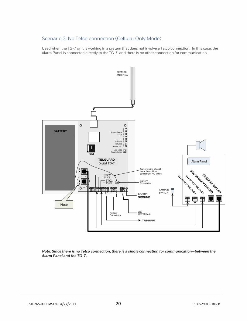
Scenario 3: No Telco connection (Cellular Only Mode)
Used when the TG-7 unit is working in a system that does not involve a Telco connection. In this case, the Alarm Panel is connected directly to the TG-7, and there is no other connection for communication.
REMOTE
ANTENNA
T
R
TELGUARD
Digital TG-7
SIM
12345678
Not Used
Not Used
Power LED
LED ModeToggle Button
System Status LEDs
Alarm Panel
Battery wire should be at least ¼ inch apart from AC wires
BATTERY
TAMPER
SWITCH
Note
Battery Connector
TRIP INPUT
EARTHGROUND
STC2(N.C.)
AC(12V 800MA)
STC1(N.O.)
1 2 3 5 6 1 21 2 1 324
Battery Connector
+-
Note: Since there is no Telco connection, there is a single connection for communication—between the Alarm Panel and the TG-7.
LS10265-000HW-E:C 04/27/2021 21 56052901 – Rev B
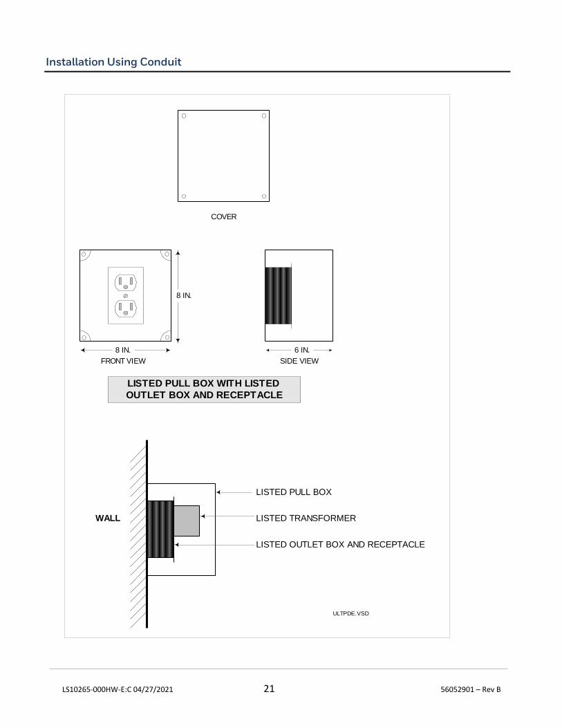
Installation Using Conduit
COVER
FRONT VIEW SIDE VIEW
6 IN.8 IN.
8 IN.
LISTED PULL BOX WITH LISTED
OUTLET BOX AND RECEPTACLE
WALL
LISTED PULL BOX
LISTED TRANSFORMER
LISTED OUTLET BOX AND RECEPTACLE
ULTPDE.VSD
LS10265-000HW-E:C 04/27/2021 22 56052901 – Rev B
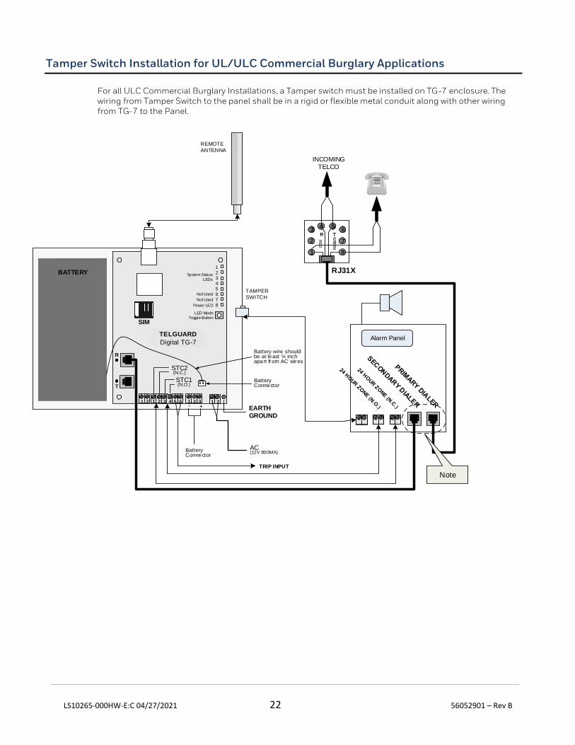
Tamper Switch Installation for UL/ULC Commercial Burglary Applications
For all ULC Commercial Burglary Installations, a Tamper switch must be installed on TG-7 enclosure. The wiring from Tamper Switch to the panel shall be in a rigid or flexible metal conduit along with other wiring from TG-7 to the Panel.
REMOTE
ANTENNA
T
R
TELGUARD
Digital TG-7
SIM
12345678
Not Used
Not Used
Power LED
LED ModeToggle Button
System Status LEDs
Alarm Panel
Battery Connector
Battery wire should be at least ¼ inch apart from AC wires
2
34 5
7G
RE
EN
R
1
T
RE
D
INCOMINGTELCO
RJ31X
TRIP INPUT
BATTERY
TAMPER
SWITCH
8
6
Note
EARTHGROUND
STC2(N.C.)
AC(12V 800MA)
STC1(N.O.)
1 2 3 5 6 1 21 2 1 324
Battery Connector
+-
LS10265-000HW-E:C 04/27/2021 23 56052901 – Rev B
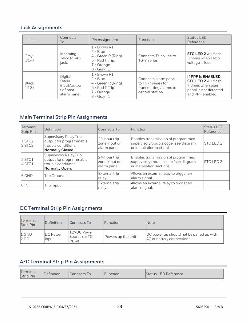
Jack Assignments
Jack Connects To
Pin Assignment Function Status LED Reference
Gray (J14)
Incoming Telco RJ-45 jack.
1 = Brown R1 2 = Blue 4 = Green R (Ring) 5 = Red T (Tip) 7 = Orange 8 = Gray T1
Connects Telco line to TG-7 series.
STC LED 2 will flash 3 times when Telco voltage is lost.
Black (J13)
Digital Dialer input/output of host alarm panel.
1 = Brown R1 2 = Blue 4 = Green R (Ring) 5 = Red T (Tip) 7 = Orange 8 = Gray T1
Connects alarm panel to TG-7 series for transmitting alarms to central station.
If PPF is ENABLED, STC LED 2 will flash 7 times when alarm panel is not detected and PPF enabled.
Main Terminal Strip Pin Assignments
Terminal Strip Pin
Definition Connects To Function Status LED Reference
1 STC2 2 STC2
Supervisory Relay Trip output for programmable trouble conditions. Normally Closed.
24-hour trip zone input on alarm panel.
Enables transmission of programmed supervisory trouble code (see diagram or installation section).
STC LED 2
3 STC1 4 STC1
Supervisory Relay Trip output for programmable trouble conditions. Normally Open.
24-hour trip zone input on alarm panel.
Enables transmission of programmed supervisory trouble code (see diagram or installation section).
STC LED 2
5 GND Trip Ground External trip relay.
Allows an external relay to trigger an alarm signal.
6 IN Trip Input External trip relay.
Allows an external relay to trigger an alarm signal.
DC Terminal Strip Pin Assignments
Terminal Strip Pin
Definition Connects To Function Note
1 GND 2 DC
DC Power input
12VDC Power Source (or TG-PEM)
Powers up the unit DC power up should not be paired up with AC or battery connections.
A/C Terminal Strip Pin Assignments
Terminal Strip Pin
Definition Connects To Function Status LED Reference
LS10265-000HW-E:C 04/27/2021 24 56052901 – Rev B
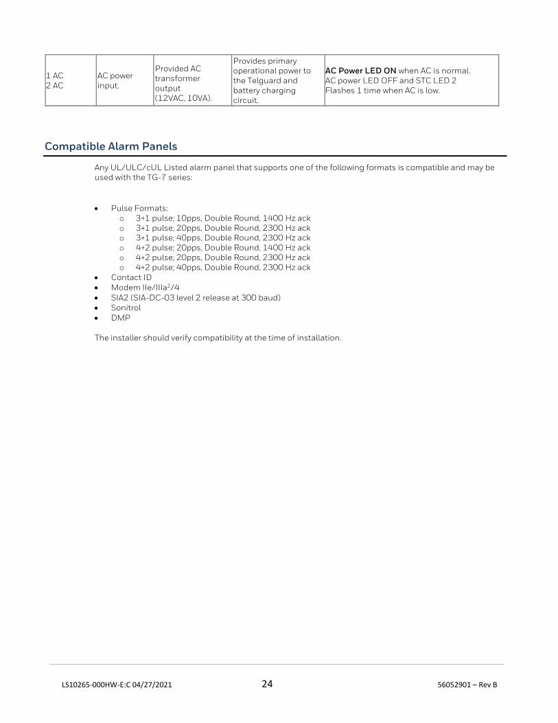
1 AC 2 AC
AC power input.
Provided AC transformer output (12VAC, 10VA).
Provides primary operational power to the Telguard and battery charging circuit.
AC Power LED ON when AC is normal. AC power LED OFF and STC LED 2 Flashes 1 time when AC is low.
Compatible Alarm Panels
Any UL/ULC/cUL Listed alarm panel that supports one of the following formats is compatible and may be used with the TG-7 series:
• Pulse Formats: o 3+1 pulse; 10pps, Double Round, 1400 Hz ack o 3+1 pulse; 20pps, Double Round, 2300 Hz ack o 3+1 pulse; 40pps, Double Round, 2300 Hz ack o 4+2 pulse; 20pps, Double Round, 1400 Hz ack o 4+2 pulse; 20pps, Double Round, 2300 Hz ack o 4+2 pulse; 40pps, Double Round, 2300 Hz ack
• Contact ID • Modem IIe/IIIa2/4 • SIA2 (SIA-DC-03 level 2 release at 300 baud) • Sonitrol • DMP
The installer should verify compatibility at the time of installation.
LS10265-000HW-E:C 04/27/2021 25 56052901 – Rev B
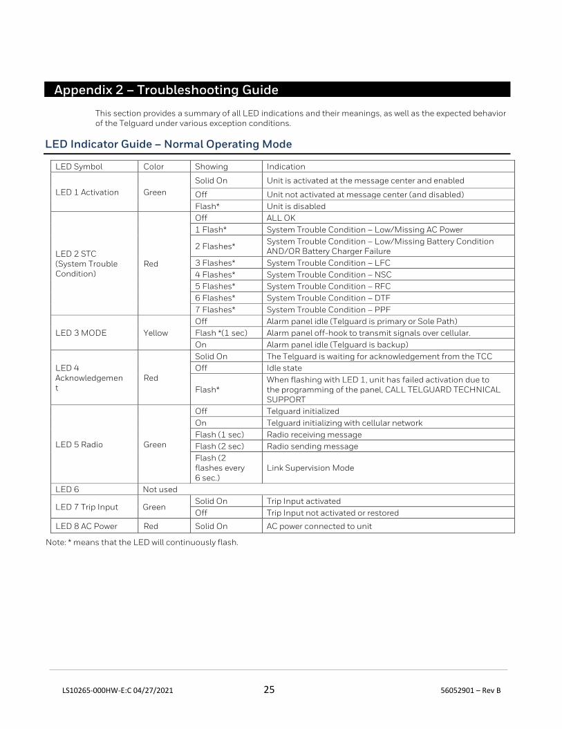
Appendix 2 – Troubleshooting Guide
This section provides a summary of all LED indications and their meanings, as well as the expected behavior of the Telguard under various exception conditions.
LED Indicator Guide – Normal Operating Mode
LED Symbol Color Showing Indication
LED 1 Activation Green
Solid On Unit is activated at the message center and enabled
Off Unit not activated at message center (and disabled)
Flash* Unit is disabled
LED 2 STC (System Trouble Condition)
Red
Off ALL OK
1 Flash* System Trouble Condition – Low/Missing AC Power
2 Flashes* System Trouble Condition – Low/Missing Battery Condition AND/OR Battery Charger Failure
3 Flashes* System Trouble Condition – LFC
4 Flashes* System Trouble Condition – NSC
5 Flashes* System Trouble Condition – RFC
6 Flashes* System Trouble Condition – DTF
7 Flashes* System Trouble Condition – PPF
LED 3 MODE Yellow
Off Alarm panel idle (Telguard is primary or Sole Path)
Flash *(1 sec) Alarm panel off-hook to transmit signals over cellular.
On Alarm panel idle (Telguard is backup)
LED 4 Acknowledgement
Red
Solid On The Telguard is waiting for acknowledgement from the TCC
Off Idle state
Flash* When flashing with LED 1, unit has failed activation due to the programming of the panel, CALL TELGUARD TECHNICAL SUPPORT
LED 5 Radio Green
Off Telguard initialized
On Telguard initializing with cellular network
Flash (1 sec) Radio receiving message
Flash (2 sec) Radio sending message
Flash (2 flashes every 6 sec.)
Link Supervision Mode
LED 6 Not used
LED 7 Trip Input Green Solid On Trip Input activated
Off Trip Input not activated or restored
LED 8 AC Power Red Solid On AC power connected to unit
Note: * means that the LED will continuously flash.
LS10265-000HW-E:C 04/27/2021 26 56052901 – Rev B
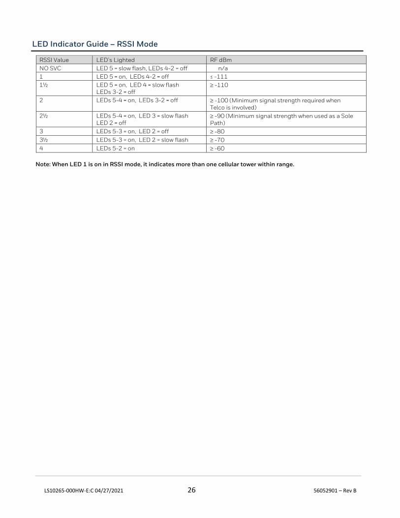
LED Indicator Guide – RSSI Mode
RSSI Value LED’s Lighted RF dBm
NO SVC LED 5 = slow flash, LEDs 4-2 = off n/a
1 LED 5 = on, LEDs 4-2 = off ≤ -111
1½ LED 5 = on, LED 4 = slow flash LEDs 3-2 = off
-110
2 LEDs 5-4 = on, LEDs 3-2 = off -100 (Minimum signal strength required when Telco is involved)
2½ LEDs 5-4 = on, LED 3 = slow flash LED 2 = off
-90 (Minimum signal strength when used as a Sole Path)
3 LEDs 5-3 = on, LED 2 = off -80
3½ LEDs 5-3 = on, LED 2 = slow flash -70
4 LEDs 5-2 = on -60
Note: When LED 1 is on in RSSI mode, it indicates more than one cellular tower within range.
LS10265-000HW-E:C 04/27/2021 27 56052901 – Rev B
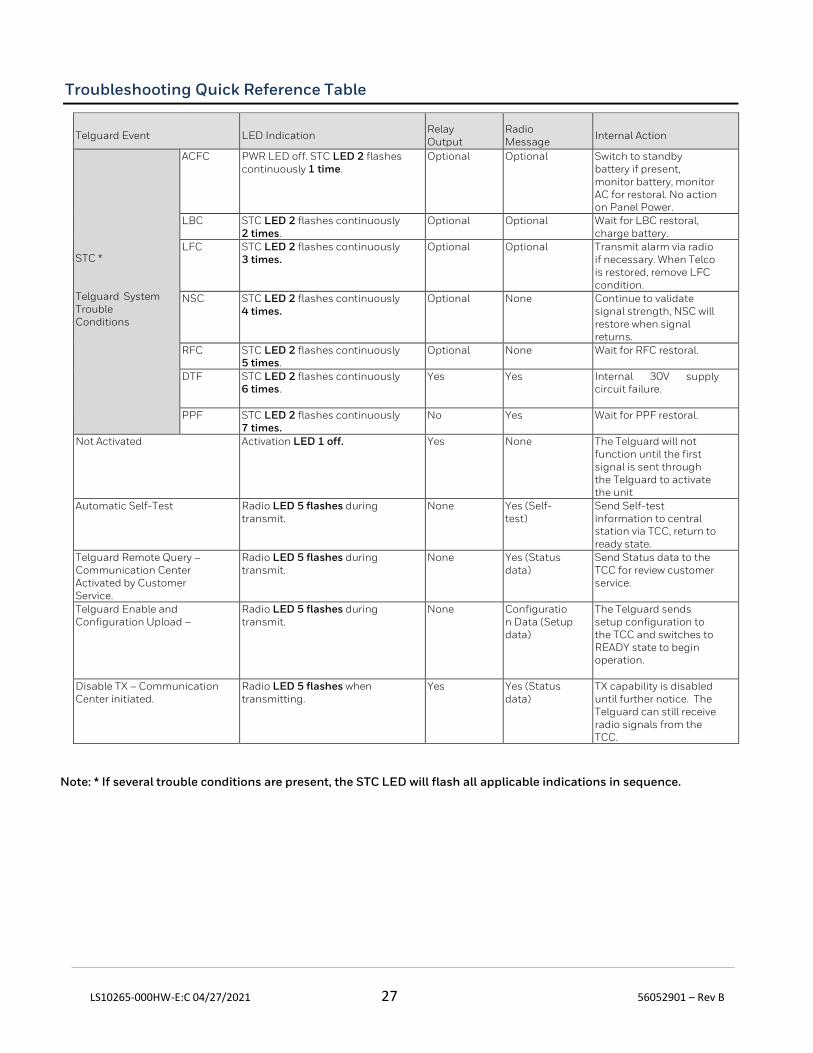
Troubleshooting Quick Reference Table
Telguard Event LED Indication Relay Output
Radio Message
Internal Action
STC * Telguard System Trouble Conditions
ACFC PWR LED off. STC LED 2 flashes continuously 1 time.
Optional Optional Switch to standby battery if present, monitor battery, monitor AC for restoral. No action on Panel Power.
LBC STC LED 2 flashes continuously 2 times.
Optional Optional Wait for LBC restoral, charge battery.
LFC STC LED 2 flashes continuously 3 times.
Optional Optional Transmit alarm via radio if necessary. When Telco is restored, remove LFC condition.
NSC STC LED 2 flashes continuously 4 times.
Optional None Continue to validate signal strength, NSC will restore when signal returns.
RFC STC LED 2 flashes continuously 5 times.
Optional None Wait for RFC restoral.
DTF STC LED 2 flashes continuously 6 times.
Yes
Yes
Internal 30V supply circuit failure.
PPF STC LED 2 flashes continuously 7 times.
No Yes Wait for PPF restoral.
Not Activated Activation LED 1 off. Yes
None The Telguard will not function until the first signal is sent through the Telguard to activate the unit
Automatic Self-Test Radio LED 5 flashes during transmit.
None Yes (Self-test)
Send Self-test information to central station via TCC, return to ready state.
Telguard Remote Query – Communication Center Activated by Customer Service.
Radio LED 5 flashes during transmit.
None Yes (Status data)
Send Status data to the TCC for review customer service.
Telguard Enable and Configuration Upload –
Radio LED 5 flashes during transmit.
None Configuration Data (Setup data)
The Telguard sends setup configuration to the TCC and switches to READY state to begin operation.
Disable TX – Communication Center initiated.
Radio LED 5 flashes when transmitting.
Yes Yes (Status data)
TX capability is disabled until further notice. The Telguard can still receive radio signals from the TCC.
Note: * If several trouble conditions are present, the STC LED will flash all applicable indications in sequence.
LS10265-000HW-E:C 04/27/2021 28 56052901 – Rev B
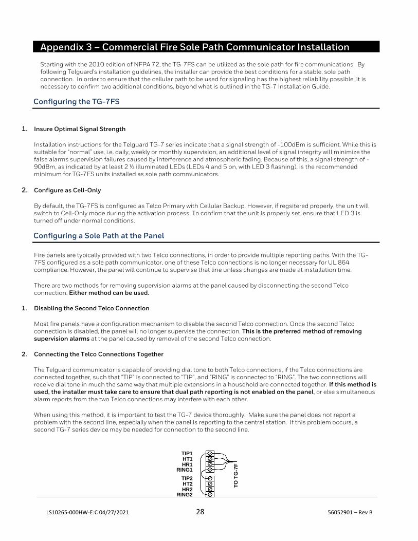
Appendix 3 – Commercial Fire Sole Path Communicator Installation
Starting with the 2010 edition of NFPA 72, the TG-7FS can be utilized as the sole path for fire communications. By following Telguard's installation guidelines, the installer can provide the best conditions for a stable, sole path connection. In order to ensure that the cellular path to be used for signaling has the highest reliability possible, it is necessary to confirm two additional conditions, beyond what is outlined in the TG-7 Installation Guide.
Configuring the TG-7FS
1. Insure Optimal Signal Strength
Installation instructions for the Telguard TG-7 series indicate that a signal strength of -100dBm is sufficient. While this is suitable for “normal” use, i.e. daily, weekly or monthly supervision, an additional level of signal integrity will minimize the false alarms supervision failures caused by interference and atmospheric fading. Because of this, a signal strength of -90dBm, as indicated by at least 2 ½ illuminated LEDs (LEDs 4 and 5 on, with LED 3 flashing), is the recommended minimum for TG-7FS units installed as sole path communicators.
2. Configure as Cell-Only
By default, the TG-7FS is configured as Telco Primary with Cellular Backup. However, if regsitered properly, the unit will switch to Cell-Only mode during the activation process. To confirm that the unit is properly set, ensure that LED 3 is turned off under normal conditions.
Configuring a Sole Path at the Panel
Fire panels are typically provided with two Telco connections, in order to provide multiple reporting paths. With the TG-7FS configured as a sole path communicator, one of these Telco connections is no longer necessary for UL 864 compliance. However, the panel will continue to supervise that line unless changes are made at installation time.
There are two methods for removing supervision alarms at the panel caused by disconnecting the second Telco connection. Either method can be used.
1. Disabling the Second Telco Connection
Most fire panels have a configuration mechanism to disable the second Telco connection. Once the second Telco connection is disabled, the panel will no longer supervise the connection. This is the preferred method of removing supervision alarms at the panel caused by removal of the second Telco connection.
2. Connecting the Telco Connections Together
The Telguard communicator is capable of providing dial tone to both Telco connections, if the Telco connections are connected together, such that “TIP” is connected to “TIP”, and “RING” is connected to “RING”. The two connections will receive dial tone in much the same way that multiple extensions in a household are connected together. If this method is used, the installer must take care to ensure that dual path reporting is not enabled on the panel, or else simultaneous alarm reports from the two Telco connections may interfere with each other.
When using this method, it is important to test the TG-7 device thoroughly. Make sure the panel does not report a problem with the second line, especially when the panel is reporting to the central station. If this problem occurs, a second TG-7 series device may be needed for connection to the second line.
TIP1
RING1HR1HT1
TIP2
RING2HR2HT2 T
O T
G-7
F

LS10265-000HW-E:C 04/27/2021 29 56052901 – Rev B
Appendix 4 – Commercial Fire 6-hour Supervision
The NFPA 72 2013 Edition updated the requirement to supervise the transmission path at least once every 6 hours, from an earlier version of 24 hours. This requirement is upheld in 2016 edition as well. Telguard commercial and fire products support this feature, and it must be enabled for each subscriber by selecting 6-hour supervision during registration.
Appendix 5 – Compliance with UL and ULC Standards
UL Installation Requirements Summary
Household Burglary
Household Fire
Household Burg/Fire Combination
Central Station Burg
Central Station Burg
Police Connect Burg Grade A
Bank, Safe and Vault
Commercial Fire
Commercial Fire & Central Station Burg
TG-7 TG-7 or TG7FS
TG-7 or TG-7FS
TG-7 TG-7A TG-7A TG-7A TG-7FS TG-7A Telguard Model
O O O Y Y Y Y* O Y UL Listed Bell and Bell Housing **
O O O O O O Y Y Y AC transformer lines in flexible conduit.
Y Y Y Y Y Y Y Y Y AC transformer plugged into un-switched outlet.
O O O O O O Y Y Y AC transformer plugged into dedicated branch circuit.
- - - N N N N N N PBX connection to RJ31X jack.
O O O O Y Y Y O Y Enclosure Tamper Switch connected to 24-hour circuit.
O O O O Y Y Y Y Y Antenna cable in flexible conduit concealed
O O O O Y Y Y O Y Attack resistant enclosure (APC-32S).
24 hrs. Use 7ah.
24 hrs. Use 7ah.
24 hrs. Use 7ah.
24 hrs. Use 7ah.
24 hrs. Use 7ah.
24 hrs. Use 7ah.
72 hrs. Use 7ah
24 hrs. Use 7ah.
24 hrs. Use 7ah.
12V. Battery backup requirement. #
* Must be connected to alarm panel UL Listed for Bank and Vault ** Use Mercantile Listed bell and bell housing # This requirement may be met by powering the TG-7 Series device from a DC alarm panel that has battery backup.
O=Optional (Not Required) Y=Yes (Required) N=No (Not Allowed)
LS10265-000HW-E:C 04/27/2021 30 56052901 – Rev B
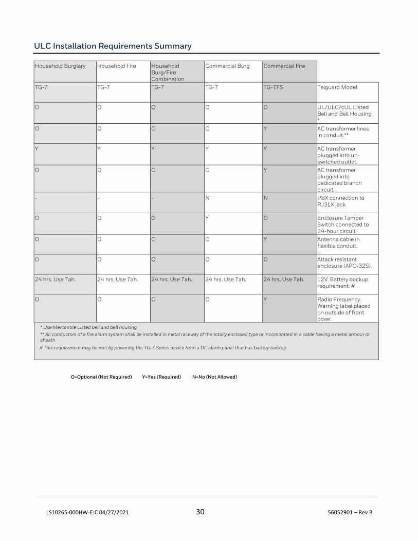
ULC Installation Requirements Summary
* Use Mercantile Listed bell and bell housing
** All conductors of a fire alarm system shall be installed in metal raceway of the totally enclosed type or incorporated in a cable having a metal armour or sheath
# This requirement may be met by powering the TG-7 Series device from a DC alarm panel that has battery backup.
O=Optional (Not Required) Y=Yes (Required) N=No (Not Allowed)
Household Burglary Household Fire Household Burg/Fire Combination
Commercial Burg Commercial Fire
TG-7 TG-7 TG-7 TG-7 TG-7FS Telguard Model
O O O O O UL/ULC/cUL Listed Bell and Bell Housing *
O O O O Y AC transformer lines in conduit.**
Y Y Y Y Y AC transformer plugged into un-switched outlet.
O O O O Y AC transformer plugged into dedicated branch circuit.
- - - N N PBX connection to RJ31X jack.
O O O Y O Enclosure Tamper Switch connected to 24-hour circuit.
O O O O Y Antenna cable in flexible conduit.
O O O O O Attack resistant enclosure (APC-32S).
24 hrs. Use 7ah. 24 hrs. Use 7ah. 24 hrs. Use 7ah. 24 hrs. Use 7ah. 24 hrs. Use 7ah. 12V. Battery backup requirement. #
O O O O Y Radio Frequency Warning label placed on outside of front cover.
LS10265-000HW-E:C 04/27/2021 31 56052901 – Rev B
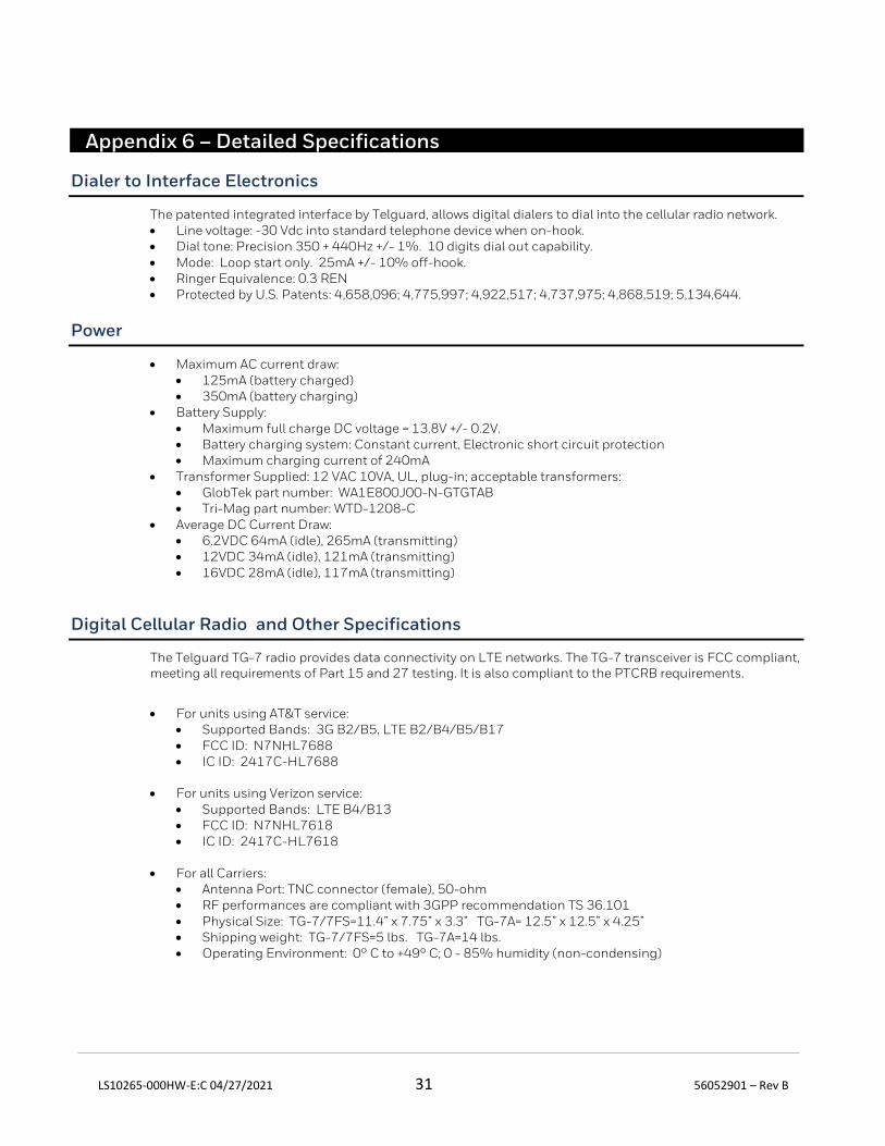
Appendix 6 – Detailed Specifications
Dialer to Interface Electronics
The patented integrated interface by Telguard, allows digital dialers to dial into the cellular radio network. • Line voltage: -30 Vdc into standard telephone device when on-hook. • Dial tone: Precision 350 + 440Hz +/- 1%. 10 digits dial out capability. • Mode: Loop start only. 25mA +/- 10% off-hook. • Ringer Equivalence: 0.3 REN • Protected by U.S. Patents: 4,658,096; 4,775,997; 4,922,517; 4,737,975; 4,868,519; 5,134,644.
Power
• Maximum AC current draw: • 125mA (battery charged) • 350mA (battery charging)
• Battery Supply: • Maximum full charge DC voltage = 13.8V +/- 0.2V. • Battery charging system: Constant current, Electronic short circuit protection • Maximum charging current of 240mA
• Transformer Supplied: 12 VAC 10VA, UL, plug-in; acceptable transformers: • GlobTek part number: WA1E800J00-N-GTGTAB • Tri-Mag part number: WTD-1208-C
• Average DC Current Draw: • 6.2VDC 64mA (idle), 265mA (transmitting) • 12VDC 34mA (idle), 121mA (transmitting) • 16VDC 28mA (idle), 117mA (transmitting)
Digital Cellular Radio and Other Specifications
The Telguard TG-7 radio provides data connectivity on LTE networks. The TG-7 transceiver is FCC compliant, meeting all requirements of Part 15 and 27 testing. It is also compliant to the PTCRB requirements.
• For units using AT&T service:
• Supported Bands: 3G B2/B5, LTE B2/B4/B5/B17 • FCC ID: N7NHL7688 • IC ID: 2417C-HL7688
• For units using Verizon service:
• Supported Bands: LTE B4/B13 • FCC ID: N7NHL7618 • IC ID: 2417C-HL7618
• For all Carriers:
• Antenna Port: TNC connector (female), 50-ohm • RF performances are compliant with 3GPP recommendation TS 36.101 • Physical Size: TG-7/7FS=11.4” x 7.75” x 3.3” TG-7A= 12.5” x 12.5” x 4.25” • Shipping weight: TG-7/7FS=5 lbs. TG-7A=14 lbs. • Operating Environment: 0° C to +49° C; 0 - 85% humidity (non-condensing)
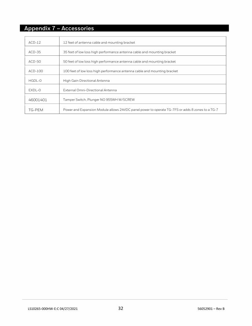
LS10265-000HW-E:C 04/27/2021 32 56052901 – Rev B
Appendix 7 – Accessories
ACD-12 12 feet of antenna cable and mounting bracket
ACD-35 35 feet of low loss high performance antenna cable and mounting bracket
ACD-50 50 feet of low loss high performance antenna cable and mounting bracket
ACD-100 100 feet of low loss high performance antenna cable and mounting bracket
HGDL-0 High Gain Directional Antenna
EXDL-0 External Omni-Directional Antenna
46001401 Tamper Switch, Plunger NO 955WH W/SCREW
TG-PEM Power and Expansion Module allows 24VDC panel power to operate TG-7FS or adds 8 zones to a TG-7