home theater system - sony esupport - manuals & … theater system 4-244-183-71(1) ht-ddw650...
TRANSCRIPT

HT-DDW650 4-244-183-71(1) US
Home TheaterSystem
4-244-183-71(1)
HT-DDW650
Owner’s RecordThe model and serial numbers are located at the rear of the unit. Record the serialnumber in the space provided below. Refer to them whenever you call upon your Sonydealer regarding this product.
Model No. Serial No.
© 2003 Sony Corporation
Operating Instructions

2US
HT-DDW650 4-244-183-71(1) US
– Reorient or relocate the receiving antenna.– Increase the separation between the equipment and
receiver.– Connect the equipment into an outlet on a circuit
different from that to which the receiver isconnected.
– Consult the dealer or an experienced radio/TVtechnician for help.
CAUTIONYou are cautioned that any changes or modificationnot expressly approved in this manual could voidyour authority to operate this equipment.
Note to CATV system installer:This reminder is provided to call CATV systeminstaller’s attention to Article 820-40 of the NEC thatprovides guidelines for proper grounding and, inparticular, specifies that the cable ground shall beconnected to the grounding system of the building, asclose to the point of cable entry as practical.
ENERGY STAR® is a U.S. registeredmark.As an ENERGY STAR® partner, SonyCorporation has determined that thisproduct meets the ENERGY STAR®
guidelines for energy efficiency.
This receiver incorporates Dolby* Digital and ProLogic Surround and the DTS** Digital SurroundSystem.* Manufactured under license from Dolby
Laboratories.“Dolby”, “Pro Logic” and the double-D symbol aretrademarks of Dolby Laboratories.
** “DTS” and “DTS Digital Surround” are registeredtrademarks of Digital Theater Systems, Inc.
WARNING
To prevent fire or shock hazard, do notexpose the unit to rain or moisture.
To prevent fire, do not cover the ventilation of theapparatus with newspapers, table-cloths, curtains, etc.And don’t place lighted candles on the apparatus.
To prevent fire or shock hazard, do not place objectsfilled with liquids, such as vases, on the apparatus.
Don’t throw away the battery withgeneral house waste, dispose of itcorrectly as chemical waste.
Do not install the appliance in a confined space, suchas a bookcase or built-in cabinet.
This symbol is intended to alert theuser to the presence of uninsulated“dangerous voltage” within theproduct’s enclosure that may be ofsufficient magnitude to constitute arisk of electric shock to persons.
This symbol is intended to alert theuser to the presence of importantoperating and maintenance (servicing)instructions in the literatureaccompanying the appliance.
WARNINGThis equipment has been tested and found to complywith the limits for a Class B digital device, pursuantto Part 15 of the FCC Rules. These limits aredesigned to provide reasonable protection againstharmful interference in a residential installation. Thisequipment generates, uses, and can radiate radiofrequency energy and, if not installed and used inaccordance with the instructions, may cause harmfulinterference to radio communications. However, thereis no guarantee that interference will not occur in aparticular installation. If this equipment does causeharmful interference to radio or television reception,which can be determined by turning the equipmentoff and on, the user is encouraged to try to correct theinterference by one or more of the followingmeasures:

3US
HT-DDW650 4-244-183-71(1) US
Table of Contents
List of Button Locations andReference Pages
Main unit ............................................... 5
Hooking Up the Components
Required cords ....................................... 6Antenna hookups ................................... 7Audio component hookups .................... 8DVD Player/Video Cassette Recorder
hookups ........................................... 9Video component hookups .................. 10Digital component hookups ................. 11Other hookups ..................................... 12
Hooking Up and Setting Upthe Speaker System
Speaker system hookups ..................... 13Performing initial setup operations ..... 15Multi channel surround setup .............. 15Checking the connections .................... 20
Basic Operations
Selecting the component ..................... 21Changing the display ........................... 22
Enjoying Surround Sound
Using only the front speakers(2 Channel Stereo) ........................ 23
Enjoying higher fidelity sound ............ 23Selecting a sound field ........................ 24Understanding the multi channel
surround displays .......................... 26Customizing sound fields .................... 27
Receiving Broadcasts
Direct tuning ........................................ 29Automatic tuning ................................. 30Preset tuning ........................................ 30
Other Operations
Naming preset stations and programsources ........................................... 32
Recording ............................................ 32Adjustments using the SET UP
menu .............................................. 33Changing the command mode of the
receiver .......................................... 34
Operations Using the RemoteRM-PP65
Before you use your remote ................ 35Remote button description ................... 35Changing the factory setting of
an input selector button ................. 38
Additional Information
Precautions .......................................... 40Troubleshooting ................................... 40Specifications ...................................... 43Tables of settings using the MAIN
MENU button ................................ 46Adjustable parameters for each sound
field ............................................... 47

4US
HT-DDW650 4-244-183-71(1) US
About This Manual
The HT-DDW650 consists of:– Receiver STR-K650P– Speaker system
• Front/surround speakers SS-MSP75• Center speaker SS-CNP75• Sub woofer SA-WMSP85
TipThe instructions in this manual describe the controlson the receiver. You can also use the controls on thesupplied remote if they have the same or similarnames as those on the receiver. For details on the useof your remote, see pages 35 – 39.
Note for the supplied remoteFor RM-PP65The >10/11 and 12 buttons on the remote arenot available.
List o
f Bu
tton
Lo
ca
tion
s an
d R
efe
ren
ce
Pa
ge
s
5US
HT-DDW650 4-244-183-71(1) US
g
?/1
qdqfqgqhqjqkqlw;wawswdwg wfwh
1 7 84 0 qa qs523 6 9
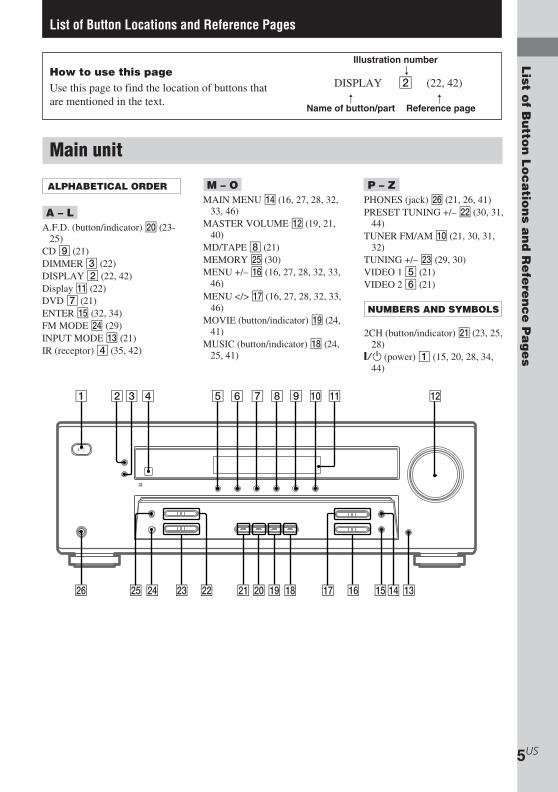
List of Button Locations and Reference Pages
Main unit
How to use this pageUse this page to find the location of buttons thatare mentioned in the text.
M – OMAIN MENU qf (16, 27, 28, 32,
33, 46)MASTER VOLUME qs (19, 21,
40)MD/TAPE 8 (21)MEMORY wg (30)MENU +/– qh (16, 27, 28, 32, 33,
46)MENU </> qj (16, 27, 28, 32, 33,
46)MOVIE (button/indicator) ql (24,
41)MUSIC (button/indicator) qk (24,
25, 41)
P – ZPHONES (jack) wh (21, 26, 41)PRESET TUNING +/– ws (30, 31,
44)TUNER FM/AM q; (21, 30, 31,
32)TUNING +/– wd (29, 30)VIDEO 1 5 (21)VIDEO 2 6 (21)
NUMBERS AND SYMBOLS
2CH (button/indicator) wa (23, 25,28)`/1 (power) 1 (15, 20, 28, 34,
44)
ALPHABETICAL ORDER
A – LA.F.D. (button/indicator) w; (23-
25)CD 9 (21)DIMMER 3 (22)DISPLAY 2 (22, 42)Display qa (22)DVD 7 (21)ENTER qg (32, 34)FM MODE wf (29)INPUT MODE qd (21)IR (receptor) 4 (35, 42)
Illustration number r
DISPLAY 2 (22, 42)R R
Name of button/part Reference page

6US
HT-DDW650 4-244-183-71(1) US
Hooking Up the Components
Before you get started
• Turn off the power to all components before making any connections.
• Do not connect the AC power cord until all of the connections are completed.
• Be sure to make connections firmly to avoid hum and noise.
• When connecting an audio/video cord, be sure to match the color-coded pins to the appropriate jacks onthe components: yellow (video) to yellow; white (left, audio) to white; and red (right, audio) to red.
• When you connect optical digital cords, insert the cord plugs straight in until they click into place.
• Do not bend or tie the optical digital cord.
Required cordsThe following optional connection cords A – E are required when you hook up the components(pages 8 – 11).
DOptical digital cord (not supplied)
ECoaxial digital cord (supplied)Orange
F Component video cord (not supplied)Green
Blue Red
AAudio cord (supplied (1 only))White (L)Red (R)
BAudio/video cord (not supplied)Yellow (video)
White (L/audio)Red (R/audio)
C Video cord (supplied (1 only))Yellow

Ho
ok
ing
Up
the
Co
mp
on
en
ts
7US
HT-DDW650 4-244-183-71(1) US
Antenna hookups
FM wire antenna(supplied)
AM loop antenna(supplied)
Notes on antenna hookups
• To prevent noise pickup, keep the AM loopantenna away from the receiver and othercomponents.
• Be sure to fully extend the FM wire antenna.
• After connecting the FM wire antenna, keep itas horizontal as possible.
L
R
y
AM
FM75Ω
COAXIAL
DIGITAL ANTENNA
MONITOR
SUBWOOFERVIDEO 1VIDEO 2DVDMD/TAPECD
OPTICAL
VIDEO 2IN
DVD IN
COAXIAL
IN OUT IN AUDIO IN AUDIO IN AUDIO OUT AUDIO IN
VIDEO IN VIDEO IN VIDEO OUT VIDEO IN VIDEO OUT
AUDIOOUT
* The shape of the connector varies depending on the area code.
*

8US
HT-DDW650 4-244-183-71(1) US
y
AM
FM75Ω
COAXIAL
DIGITAL ANTENNA
MONITOR
SUBWOOFERVIDEO 1VIDEO 2DVDMD/TAPECD
OPTICAL
VIDEO 2IN
DVD IN
COAXIAL
IN OUT IN AUDIO IN AUDIO IN AUDIO OUT AUDIO IN
VIDEO IN VIDEO IN VIDEO OUT VIDEO IN VIDEO OUT
AUDIOOUT
L
R
LINE
L
R
OUTPUT
A
INOUT
LINE
L
R
LINE
INPUT OUTPUT
ç
ç
AA
Audio component hookups
MD or Tape deck
CD player

Ho
ok
ing
Up
the
Co
mp
on
en
ts
9US
HT-DDW650 4-244-183-71(1) US
DVD Player/Video Cassette Recorder hookups
SPEAKERS IMPEDANCE USE 8 – 16Ω
y
AM
FM75Ω
COAXIAL
DIGITAL ANTENNA
MONITOR
SUBWOOFERVIDEO 2DVDMD/TAPECD
OPTICAL
VIDEO 2IN
DVD IN
COAXIAL
IN OUT IN AUDIO IN AUDIO IN AUDIO OUT AUDIO IN
VIDEO IN VIDEO IN VIDEO OUT VIDEO IN VIDEO OUT
AUDIOOUT
FRONT CENTER SURROUND
R
R
L
L
R
R
L
L
L
R
VIDEO IN
INPUT
Pr
Pb
COMPONENTVIDEO IN
Y
E
A
C F
S-VIDEO OUTDIGITAL AUDIO OUT
OPTICALR
L YPr
Pb
LINEOUT
RF
LINEIN 1
AUDIO
R
L
VIDEOOUT
(TO TV)
IN(FROM ANT.)
DVD & VCR
LINE OUT COMPONENT VIDEO OUT
AUDIO
COAXIAL
DVD Only
VIDEO 1
TV Monitor
NoteIf your TV has COMPONENT VIDEO input jacks, you can use a component video cord (not supplied) to connectthe DVD Player/Video Cassette Recorder to your TV.

10US
HT-DDW650 4-244-183-71(1) US
y
AM
FM75Ω
COAXIAL
DIGITAL ANTENNA
MONITOR
SUBWOOFERVIDEO 1VIDEO 2DVDMD/TAPECD
OPTICAL
VIDEO 2IN
DVD IN
COAXIAL
IN OUT IN AUDIO IN AUDIO IN AUDIO OUT AUDIO IN
VIDEO IN VIDEO IN VIDEO OUT VIDEO IN VIDEO OUT
AUDIOOUT
L
R
VIDEOIN
INPUT
C
IN
VIDEOOUT
R
AUDIOOUT
OUTPUT
L
Ç
B
VIDEOOUT
R
AUDIOOUT
VIDEOIN
AUDIOIN
OUTPUTINPUT
L
INOUT
Ç
Ç
B B
AUDIO OUT VIDEO OUTLR
OUTPUT
B
Video component hookupsIf you are not going to hookup a DVD Player/Video Cassette Recorder, you can hookup your videocomponents as shown below.
TV monitor
DVD player
Note on video componenthookups
You can connect your TV’s audio output jacksto the VIDEO 2 AUDIO IN jacks on thereceiver and apply sound effects to the audiofrom the TV. In this case, do not connect theTV’s video output jack to the VIDEO 2VIDEO IN jack on the receiver. If you areconnecting a separate satellite tuner, connectboth the audio and video output jacks to thereceiver as shown above.
Satellitetuner or
VCR VCR

Ho
ok
ing
Up
the
Co
mp
on
en
ts
11US
HT-DDW650 4-244-183-71(1) US
y
AM
FM75Ω
COAXIAL
DIGITAL ANTENNA
MONITOR
SUBWOOFERVIDEO 1VIDEO 2DVDMD/TAPECD
OPTICAL
VIDEO 2IN
DVD IN
COAXIAL
IN OUT IN AUDIO IN AUDIO IN AUDIO OUT AUDIO IN
VIDEO IN VIDEO IN VIDEO OUT VIDEO IN VIDEO OUT
AUDIOOUT
L
R
VIDEOOUT
R
AUDIOOUT
OUTPUT
LDIGITALOPTICAL
OUTPUT
BD
DIGITALCOAXIAL
OUTPUTVIDEOOUT
R
AUDIOOUT
OUTPUT
L
E B
Digital component hookups
DVD player (etc.)
If you are not going to hookup a DVD Player/Video Cassette Recorder, you can hookup your digitalcomponents as shown below.
Connect the digital output jacks of your DVD player and satellite tuner (etc.) to the receiver’s digitalinput jacks to bring the multi channel surround sound of a movie theater into your home. To fullyenjoy multi channel surround sound, five speakers (two front speakers, two surround speakers, and acenter speaker) and a sub woofer are required.
NoteAll the OPTICAL and COAXIAL jacks are compatible with 96 kHz, 48 kHz, 44.1 kHz and 32 kHz samplingfrequencies.
Satellite tuneror DVD player

12US
HT-DDW650 4-244-183-71(1) US
Connecting the AC powercord
Before connecting the AC power cord of thisreceiver to a wall outlet, connect the speakersystem to the receiver (page 13).
Connect the AC power cord(s) of your audio/video components to a wall outlet.
Other hookups
SPEAKERS IMPEDANCE USE 8 – 16ΩFRONT CENTER SURROUND
R
R
L
L
R
R
L
L
b
AC power cord
To a wall outlet
Ho
ok
ing
Up
an
d S
ettin
g U
p th
e S
pe
ak
er S
ystem
13US
HT-DDW650 4-244-183-71(1) US
SPEAKERS IMPEDANCE USE 8 – 16Ω
MONITOR
SUBWOOFER
VIDEO OUT
AUDIOOUT
FRONT CENTER SURROUND
R
R
L
L
R
R
L
L
E eE e
A A
INPUTAUDIO
IN
B
E e
A
E e
A
E e
A
b
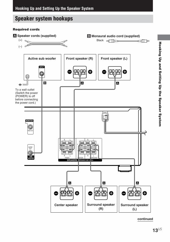
Hooking Up and Setting Up the Speaker System
Front speaker (L)Front speaker (R)
Center speaker Surround speaker(L)
Surround speaker(R)
Active sub woofer
BMonaural audio cord (supplied)Black
To a wall outlet(Switch the power(POWER) to offbefore connectingthe power cord.)
Speaker system hookups
Required cords
A Speaker cords (supplied)(+)
(–)
continued

14US
HT-DDW650 4-244-183-71(1) US
Examples of poor conditions of thespeaker cord
Stripped speaker cord is touching anotherspeaker terminal.
Stripped cords are touching each otherdue to excessive removal of insulation.
Stripped cords are not fully attached andare touching the rear panel of the receiver.
After connecting all the components,speakers, and AC power cord, outputa test tone to check that all thespeakers are connected correctly.For details on outputting a test tone,see page 19.
If no sound is heard from a speaker whileoutputting a test tone or a test tone is outputfrom a speaker other than the one whose nameis currently displayed on the receiver, thespeaker may be short-circuited. If this happens,check the speaker connection again.
TipTo prevent speaker vibration or movement whilelistening, attach the supplied foot pads at the bottomof the speakers.
Notes• Connect the long speaker connecting cords to the
surround speaker terminals and the short speakerconnecting cords to the front and center speakerterminals.
• Twist the stripped ends of the speaker cords about2/3 inch. Be sure to match the speaker cord to theappropriate terminal on the components: + to + and– to –. If the cords are reversed, the sound will bedistorted and will lack bass.
• If you use speakers with low maximum input rating,adjust the volume carefully to avoid excessiveoutput on the speakers.
To avoid short-circuiting thespeakers
Short-circuiting of the speakers may damagethe receiver. To prevent this, make sure to takethe following precautions when connecting thespeakers.
Make sure the stripped ends of eachspeaker cord does not touch anotherspeaker terminal, the stripped end ofanother speaker cord, or the metal parts ofthe receiver.
Speaker system hookups (continued)

Ho
ok
ing
Up
an
d S
ettin
g U
p th
e S
pe
ak
er S
ystem
15US
HT-DDW650 4-244-183-71(1) US
45°
90°
20°
B
CC
A A
To avoid damaging yourspeakers
Make sure that you turn down the volumebefore you turn off the receiver. When you turnon the receiver, the volume remains at the levelyou turn off the receiver.
Performing initial setupoperations
Once you have hooked up the speakers andturned on the power, clear the receiver’smemory. Then specify the speaker parameters(size, position, etc.) and perform any otherinitial setup operations necessary for yoursystem.
TipTo check the audio output during settings (to set upwhile outputting the sound), check the connection(page 20).
Clearing the receiver’smemory
Before using your receiver for the first time, orwhen you want to clear the receiver’s memory,do the following.
1 Turn off the receiver.
2 Hold down ?/1 for 5 seconds.“INITIAL” appears in the display.The following are reset to their factorysettings.
• All settings in the SET UP, LEVEL andTONE menus.
• The sound field memorized for eachinput selector and preset station.
• All sound field parameters.• All preset stations.• All index names of input selectors and
preset stations.• The master volume is set to “VOL
MIN”.
Performing initial setupoperations
Before using your receiver for the first time,adjust SET UP parameters so that the receivercorrespond to your system. For the adjustableparameters, see the table on page 46. See pages15–19 for speaker settings and page 33 forother settings.
Multi channel surroundsetup
For the best possible surround sound, allspeakers should be the same distance from thelistening position (A).
However, the receiver lets you place the centerspeaker up to 5 feet closer (B) and thesurround speakers up to 15 feet closer (C) tothe listening position.
The front speakers can be placed from 3 to 23feet from the listening position (A).
You can place the surround speakers eitherbehind you or to the side, depending on theshape of your room (etc.). However, werecommend that you place the surroundspeakers behind you.
When placing surround speakers to your side(long room)
Sub woofer
continued

16US
HT-DDW650 4-244-183-71(1) US
45°
90°
20°
B
CC
AA
When placing surround speakers behind you(wide room)
NoteDo not place the center speaker further away from thelistening position than the front speakers.
Normal Speaker and MicroSatellite Speaker
For HT-DDW650, the speaker size and the subwoofer selection has been preset to “MICROSP.” (Micro Satellite Speaker) according to thesupplied speaker system.
When you select “MICRO SP.”, the speakersize and sub woofer selection has beenconfigurated as follows:
Speaker Settings
FRONT SMALL
CENTER SMALL
SURROUND SMALL
SUB WOOFER YES
You cannot change the configuration if youselect “MICRO SP.”.
If you change the speaker system, select“NORM. SP.”. You can adjust the speaker sizeand sub woofer selection when you select“NORM. SP.” (page 18).
To select “NORM. SP.”, turn off the power,then turn on again while pressing MAINMENU. (To reset to “MICRO SP.”, do thesame procedure.)
TipThe setting for Micro Satellite Speaker (MICRO SP.)has been programmed to optimize the sound balance.If you use Sony’s Micro Satellite Speakers, select“MICRO SP.”.
CautionWhen you use Micro Satellite Speakers and thespeaker size is set to “LARGE”, you may not obtainthe correct soundstage. The speaker may also bedamaged at high volume position.
Specifying the speakerparameters
1 Press MAIN MENU repeatedly to select“ SET UP ”.
2 Press MENU or MENU to selectthe parameter you want to adjust.
3 Press MENU + or MENU – to select thesetting you want.The setting is entered automatically.
4 Repeat steps 2 and 3 until you have setall of the parameters that follow.
Initial settings
Parameter Initial settingL R DIST. XX ft. 10 ft.
C DIST. XX ft. 10 ft.
SL SR DIST. XX ft. 10 ft.
SL SR PL. XXXX LOW
Sub woofer
Multi channel surround setup(continued)

Ho
ok
ing
Up
an
d S
ettin
g U
p th
e S
pe
ak
er S
ystem
17US
HT-DDW650 4-244-183-71(1) US
60
30A
B
A
B
x Front speaker distance ( L R DIST.XX ft.)
Set the distance from your listening position tothe front speakers (A on page 15).
x Center speaker distance ( C DIST.XX ft.)
Set the distance from your listening position tothe center speaker. Center speaker distanceshould be set from a distance equal to the frontspeaker distance (A on page 15) to a distance5 feet closer to your listening position (B onpage 15).
x Surround speaker distance ( SL SR
DIST. XX ft.)Set the distance from your listening position tothe surround speakers. Surround speakerdistance should be set from a distance equal tothe front speaker distance (A on page 15) to adistance 15 feet closer to your listeningposition (C on page 15).
TipThe receiver allows you to input the speaker positionin terms of distance. However, it is not possible to setthe center speaker further than the front speakers.Also, the center speaker cannot be set more than5 feet closer than the front speakers.Likewise, the surround speakers can not be set furtheraway from the listening position than the frontspeakers. And they can be no more than 15 feetcloser.This is because incorrect speaker placement is notconducive to enjoy surround sound.Please note that, setting the speaker distance closerthan the actual location of the speakers will cause adelay in the output of the sound from that speaker. Inother words, the speaker will sound like it is furtheraway.
For example, setting the center speaker distance3~6 feet closer than the actual speaker position willcreate a fairly realistic sensation of being “inside” thescreen. If you cannot obtain a satisfactory surroundeffect because the surround speakers are too close,setting the surround speaker distance closer (shorter)than the actual distance will create a larger soundstage.Adjusting these parameter while listening to thesound often results in much better surround sound.Give it a try!
x Surround speaker placement ( SL SR
PL. XXXX)*This parameter lets you specify the height ofyour surround speakers for properimplementation of the Digital Cinema Soundsurround modes. Refer to the illustration below.
• Select “PL. LOW” if the location of yoursurround speakers corresponds to section A.
• Select “PL. HIGH” if the location of yoursurround speakers corresponds to section B.
* These parameters are not available when“Surround speaker size ( SL SR )” is set to “NO”.
continued
18US
HT-DDW650 4-244-183-71(1) US
Multi channel surround setup(continued)
TipThe surround speaker placement parameter isdesigned specifically for implementation of theDigital Cinema Sound modes with virtual elements.With the Digital Cinema Sound modes, speakerplacement is not as critical as other modes. All modeswith virtual elements were designed under thepremise that the surround speaker would be locatedbehind the listening position, but presentation remainsfairly consistent even with the surround speakerspositioned at a rather wide angle. However, if thespeakers are pointing towards the listener from theimmediate left and right of the listening position, thesound fields with virtual elements will not be aseffective.Nevertheless, each listening environment has manyvariables, like wall reflections.Therefore, we recommend that you playback multichannel surround encoded software and listen to theeffect each setting has on your listening environment.Choose the setting that provides a good sense ofspaciousness and that best succeeds in forming acohesive space between the surround sound from thesurround speakers and the sound of the frontspeakers. If you are not sure which sounds best, select“PL. LOW” and then use the speaker distanceparameter and speaker level adjustments to obtainproper balance.
Only when you use the speaker systemother than the supplied one, be sure toset the following parameters.For details on “NORM. SP.” (Normal Speaker), seepage 16.
x Sub woofer selection ( SW S.W. XXX)
• If you connect a sub woofer, select “YES”.
• If you do not connect a sub woofer, select“NO”. This activates the bass redirectioncircuitry and outputs the LFE signals from otherspeakers.
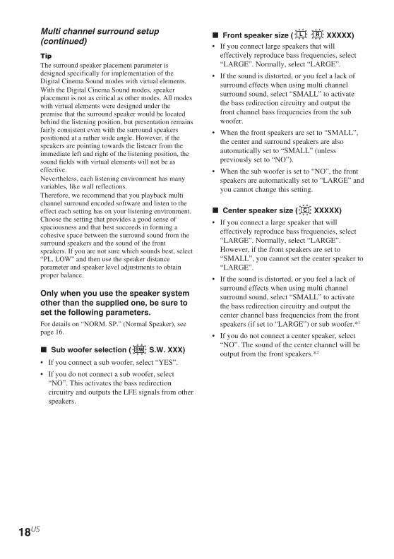
x Front speaker size ( L R XXXXX)• If you connect large speakers that will
effectively reproduce bass frequencies, select“LARGE”. Normally, select “LARGE”.
• If the sound is distorted, or you feel a lack ofsurround effects when using multi channelsurround sound, select “SMALL” to activatethe bass redirection circuitry and output thefront channel bass frequencies from the subwoofer.
• When the front speakers are set to “SMALL”,the center and surround speakers are alsoautomatically set to “SMALL” (unlesspreviously set to “NO”).
• When the sub woofer is set to “NO”, the frontspeakers are automatically set to “LARGE” andyou cannot change this setting.
x Center speaker size ( C XXXXX)
• If you connect a large speaker that willeffectively reproduce bass frequencies, select“LARGE”. Normally, select “LARGE”.However, if the front speakers are set to“SMALL”, you cannot set the center speaker to“LARGE”.
• If the sound is distorted, or you feel a lack ofsurround effects when using multi channelsurround sound, select “SMALL” to activatethe bass redirection circuitry and output thecenter channel bass frequencies from the frontspeakers (if set to “LARGE”) or sub woofer.*1
• If you do not connect a center speaker, select“NO”. The sound of the center channel will beoutput from the front speakers.*2

Ho
ok
ing
Up
an
d S
ettin
g U
p th
e S
pe
ak
er S
ystem
19US
HT-DDW650 4-244-183-71(1) US
x Surround speaker size ( SL SR
XXXXX)• If you connect large speakers that will
effectively reproduce bass frequencies, select“LARGE”. Normally, select “LARGE”.However, if the front speakers are set to“SMALL”, you cannot set the surroundspeakers to “LARGE”.
• If the sound is distorted, or you feel a lack ofsurround effects when using multi channelsurround sound, select “SMALL” to activatethe bass redirection circuitry and output thesurround channel bass frequencies from the subwoofer or other “LARGE” speakers.
• If you do not connect surround speakers, select“NO”.*3
Tip*1–*3 correspond to the following Dolby Pro Logicmodes*1 NORMAL*2 PHANTOM*3 3 STEREO
TipInternally, the LARGE and SMALL settings for eachspeaker determine whether the internal soundprocessor will cut the bass signal from that channel.When the bass is cut from a channel, the bassredirection circuitry sends the corresponding bassfrequencies to the sub woofer or other “LARGE”speakers.However, since bass sounds have a certain amount ofdirectionality, it is best not to cut them, if possible.Therefore, even when using small speakers, you canset them to “LARGE” if you want to output the bassfrequencies from that speaker. On the other hand, ifyou are using a large speaker, but prefer not to havebass frequencies output from that speaker, set it to“SMALL”.If the overall sound level is lower than you prefer, setall speakers to “LARGE”. If there is not enough bass,you can use the BASS parameter in the TONE menuto boost the bass levels. To adjust the bass, see page28.
Adjusting the speaker level
Use the remote while seated in your listeningposition to adjust the level of each speaker.
NoteThe receiver incorporates a new test tone with afrequency centered at 800 Hz for easier speaker leveladjustment.
1 Press ?/1 on the remote to turn on thereceiver.
2 Press T.TONE on the remote.“T. TONE” appears in the display and youwill hear the test tone from each speaker insequence.Front (left) t Center t Front (right) tSurround (right) t Surround (left) tSub woofer
3 Adjust the speaker level and balanceusing the LEVEL menu so that the levelof the test tone sounds the same fromeach speaker.For details on the LEVEL menu, see page27.While adjusting, the test tone is output fromthe speaker whose adjustment is performed.
4 Press T.TONE again to turn off the testtone.
TipYou can adjust the level of all speakers at the sametime. Press MASTER VOL +/– on the remote or turnMASTER VOLUME on the receiver.
Notes• The adjusted value are shown in the display during
adjustment.• Although these adjustments can also be made via
the front panel using the LEVEL menu (when thetest tone is output, the receiver switches to theLEVEL menu automatically), we recommend youfollow the procedure described above and adjust thespeaker levels from your listening position using theremote.
continued

20US
HT-DDW650 4-244-183-71(1) US
LEVEL
POWER
POWER indicator
Listening to the sub woofer
First, turn down the volume on the receiver.The volume should be set to minimum beforeyou begin playing the program source.
1 Turn on the receiver and select theprogram source.
2 Press POWER on the sub woofer.
The POWER indicator on the sub wooferlights up in green.
3 Play the program source.
Adjusting the sound
Slight adjustments to the system can enhanceyour sound enjoyment.
Adjusting the sub woofer
1 Rotate LEVEL to adjust the volume.
Set the volume level to best suit yourpreference according to the program source.
NoteDo not turn the volume of the woofer to maximum.Extraneous noise may be heard.
Checking the connectionsAfter connecting all of your components to thereceiver, do the following to verify that theconnections were made correctly.
1 Press ?/1 to turn on the receiver.
2 Turn on the component that youconnected (e.g., CD player or tapedeck).
3 Press the input selector button (e.g.,CD or MD/TAPE) to select thecomponent (program source).
4 Start playing.
If you do not obtain normal sound output afterperforming this procedure, see“Troubleshooting” on page 40 and take theappropriate measures to correct the problem.
Multi channel surround setup(continued)

Ba
sic O
pe
ratio
ns
21US
HT-DDW650 4-244-183-71(1) US
Basic Operations
Selecting the component
Input Selector buttons
Press the input selector button to select thecomponent you want to use.
To select Press
DVD PLAYER/VIDEO DVDCASSETTE RECORDER(DVD mode)
DVD PLAYER/VIDEO VIDEO 1CASSETTE RECORDER(VIDEO mode)
Other VCR VIDEO 2
MD or Tape deck MD/TAPE
CD player CD
Built in tuner TUNER FM/AM
After turning on the component you selected,select the component and play the programsource.
• After selecting DVD PLAYER/VIDEOCASSETTE RECORDER, VCR or DVDplayer, turn on the TV and set the TV’s videoinput to match the component you selected.
INPUT MODE
Press INPUT MODE to select the input modefor your digital components.Each time you press the button, the input modeof the currently selected component switches.
Select To
AUTO IN Give priority to digitalsignals when there are bothdigital and analogconnections. If there are nodigital signals, analog isselected.
COAX IN Specify the digital audiosignals input to theDIGITAL COAXIAL inputjacks.
Select To
OPT IN Specify the digital audiosignals input to theDIGITAL OPTICAL inputjacks.
ANALOG Specify the analog audiosignals input to the AUDIOIN (L/R) jacks.
NoteWhen the 96 kHz digital signal is input, the tone,sound field and effect level do not function.
MUTING
Press MUTING on the remote to mute thesound. Press again to cancel the mutingfunction. The muting function is also canceledwhen you turn the power on or turn theMASTER VOLUME to turn the volume up.
PHONES
Use to connect headphones.
• When the headphones are connected, speakeroutput is automatically canceled and “SP” donot light up in the display.

22US
HT-DDW650 4-244-183-71(1) US
Changing the display
DIMMER
Press DIMMER repeatedly to adjust thebrightness of the display (3 steps).However, when you press any button, thedisplay becomes the brightest settingtemporary.
DISPLAY
Each time you press DISPLAY, the displaychanges cyclically as follows:
Index name of the component* t Selectedcomponent t Sound field applied to theprogram source
When the tuner is selectedIndex name of the preset station* tFrequency t Sound field applied to the bandor the preset station
* Index name appears only when you have assignedone to the component or preset station (page 32).Index name does not appear when only blankspaces have been entered, or it is the same as theinput selector.

En
joyin
g S
urro
un
d S
ou
nd
23US
HT-DDW650 4-244-183-71(1) US
Enjoying Surround Sound
Enjoying higher fidelitysound
The Auto Format Direct (A.F.D.) mode allowsyou to select the decoding mode you want foryour audio sound.
Mode Decoding Mode
A.F.D. AUTO As encoded
DOLBY PL Dolby Pro Logic
PLII MOVDolby Pro Logic II
PLII MUS
Decoding the input audiosignal automatically
Press A.F.D. repeatedly to select “A.F.D.AUTO”.The A.F.D. indicator lights up.
This mode automatically detects the type ofaudio signal being input (Dolby Digital, DTS,or standard 2 channel stereo) and performs theproper decoding if necessary. This modepresents the sound as it was recorded/encoded,without adding any effects (e.g. reverberation).
However, if there are no low frequency signals(Dolby Digital LFE, etc.) it will generate a lowfrequency signal for output to the sub woofer.
You can take advantage of surround soundsimply by selecting one of the receiver’s pre-programmed sound fields. They bring theexciting and powerful sound of movie theatersand concert halls into your home. You can alsocustomize the sound fields to obtain the soundyou want by changing the surround parameter.To fully enjoy surround sound, you mustregister the number and location of yourspeakers. See “Multi channel surround setup”starting from page 15 to set the speakerparameters before enjoying surround sound.
Using only the frontspeakers (2 Channel Stereo)
Press 2CH.The 2CH indicator lights up and “2CH ST.”appears in the display.
This mode outputs the sound from the front leftand right speakers only. Standard 2 channel(stereo) sources completely bypass the soundfield processing. Multi channel surroundformats are downmixed to 2 channel.
Notes• No sound is output from the sub woofer when
“2CH ST.” is selected. To listen to 2 channel(stereo) sources using the front left and rightspeakers and a sub woofer, press A.F.D. repeatedlyto select “A.F.D. AUTO”.
• When you select “Micro Satellite Speaker” (page16), internal sound processor will automaticallyredirect bass sound to sub woofer. If you want tolisten to two channel (stereo) sources under thissetting, we recommend that you choose“A.F.D. AUTO” mode so that you can takeadvantage of your sub woofer to obtain the correctbass signal.
continued

24US
HT-DDW650 4-244-183-71(1) US
Enjoying higher fidelity sound(continued) Selecting a sound field
You can enjoy surround sound simply byselecting one of the pre-programmed soundfields according to the program you want tolisten to.
Press To select
MOVIE C.ST.EX A DCS *
C.ST.EX B DCS *
C.ST.EX C DCS *
MUSIC HALL
JAZZ
CONCERT
* Sound field with DCS mark use DCS technology.
About DCS (Digital Cinema Sound)In collaboration with Sony PicturesEntertainment, Sony measured the soundenvironment of their studios and integrated thedata of the measurement and Sony’s own DSP(Digital Signal Processor) technology todevelop “Digital Cinema Sound”. In a hometheater, “Digital Cinema Sound” simulates anideal movie theater sound environment basedon the preference of the movie director.
Enjoying movies with CinemaStudio EX
Cinema Studio EX is ideal for enjoying themovie software encoded with multi channelformat, such as the Dolby Digital DVD. Thismode reproduces the sound characteristics ofSony Pictures Entertainment’s studios.
Press MOVIE repeatedly to select“C.ST.EX A”, “C.ST.EX B” or “C.ST.EX C”.The MOVIE indicator lights up and theselected sound field is indicated in the display.
Enjoying stereo sound inmulti channel (Dolby ProLogic )
This receiver incorporates with Dolby ProLogic II which has movie mode and musicmode, and the receiver can reproduce the 2channel sound in 5.1 channel through DolbyPro Logic II.
Press A.F.D. repeatedly to select “DOLBYPL”, “PL MOV” or “PL MUS”.The A.F.D. indicator lights up and the selectedtype of decoding is indicated in the display.
x DOLBY PL (Dolby Pro Logic)Performs the Pro Logic decoding. Softwarewith multi channel surround audio signals isplayed back according to the way it wasrecorded. Software with 2 channel audiosignals is decoded with Dolby Pro Logic tocreate surround effects (4 channels).
x PL MOV (Pro Logic Movie)Performs the Pro Logic II movie modedecoding. This setting is ideal for the moviesencoded in Dolby Surround. Besides, this modecan reproduce the sound in 5.1 channel whenwatching the videos of old movies or in thedubbed language.
x PL MUS (Pro Logic Music)Performs the Pro Logic II music mode decoding.This setting is ideal for the normal stereosources, such as CDs.
NoteDolby Pro Logic and Dolby Pro Logic II decodingdoes not function for DTS format signals.

En
joyin
g S
urro
un
d S
ou
nd
25US
HT-DDW650 4-244-183-71(1) US
Selecting other sound fields
Press MUSIC repeatedly to select thesound field you want.The MUSIC indicator lights up and the currentsound field is indicated in the display.
x HALLReproduces the acoustics of a rectangularconcert hall.
x JAZZ (Jazz Club)Reproduces the acoustics of a jazz club.
x CONCERT (Live Concert)Reproduces the acoustics of a 300-seat liveconcert.
To turn the surround effect offPress A.F.D. repeatedly to select “A.F.D.AUTO” or press 2CH.
Tips• The receiver lets you apply the last selected sound
field to a program source whenever it is selected(Sound Field Link). For example, if you listen toCD with “JAZZ” as the sound field, change to adifferent program source, then return to CD,“JAZZ” will be applied again.
• You can identify the encoding format of DVDsoftware, etc. by looking at the logo on thepackage.– : Dolby Digital discs– : Dolby Surround encoded
programs– : DTS Digital Surround encoded programs
• When sound signals with a sampling frequency of96 kHz are input, the sound signals are output instereo automatically, and the sound field is turnedoff.
x C.ST.EX A (Cinema Studio EX A)Reproduces the sound characteristics of theSony Pictures Entertainment “Cary GrantTheater” cinema production studio. This is astandard mode, great for watching most anytype of movie.
x C.ST.EX B (Cinema Studio EX B)Reproduces the sound characteristics of theSony Pictures Entertainment “Kim NovakTheater” cinema production studio. This modeis ideal for watching science-fiction or actionmovies with lots of sound effects.
x C.ST.EX C (Cinema Studio EX C)Reproduces the sound characteristics of theSony Pictures Entertainment scoring stage.This mode is ideal for watching musicals orclassic films where music is featured in thesoundtrack.
About Cinema Studio EXCinema Studio EX consists of the followingthree elements.
• Virtual Multi Dimension
Creates 5 sets of virtual speakerssurrounding the listener from a single pair ofactual surround speakers.
• Screen Depth Matching
In a movie theater, sound seems to comefrom inside the image reflected on the moviescreen. This element creates the samesensation in your listening room by shiftingthe sound of the front speakers “into” thescreen.
• Cinema Studio Reverberation
Reproduces the reverberations peculiar to amovie theater.
Cinema Studio EX is the integrated modewhich operates these elements simultaneously.
Notes• The effects provided by the virtual speakers may
cause increased noise in the playback signal.• When listening with sound fields that employ the
virtual speakers, you will not be able to hear anysound coming directly from the surround speakers.

26US
HT-DDW650 4-244-183-71(1) US
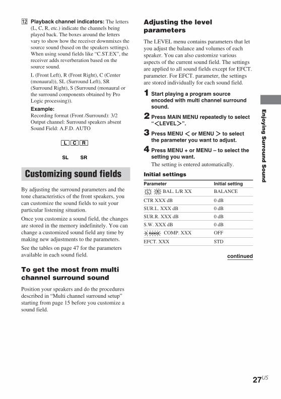
Understanding the multi channel surround displays
STEREOD.RANGECOAXOPT MONOMEMORYDIGITALSP PRO LOGIC IIa a
SLEEP
DTS
L C R
SW
SL SRS
LFE
1 2 3 4 5 6
789q;
qaqs
6 Tuner indicators: Lights up when using thereceiver to tune in radio stations, etc. Seepages 29 – 31 for tuner operations.
7 SLEEP: Lights up when sleep timer isactivated.
8 D.RANGE: Lights up when dynamic rangecompression is activated. See page 27 toadjust the dynamic range compression.
9 COAX: Lights up when the source signal is adigital signal being input through theCOAXIAL terminal.
0 OPT: Lights up when the source signal is adigital signal being input through theOPTICAL terminal.
qa LFE: Lights up when the disc being playedback contains the LFE (Low FrequencyEffect) channel and when the sound of theLFE channel signal is actually beingreproduced.
1 SW: Lights up when sub woofer selection isset to “YES” (page 18) and the audio signal isoutput from the SUB WOOFER jacks.
2 SP: Lights up when you turn on the receiver.
NoteDoes not light up when you connect headphonesto the PHONES jack.
3 ; DIGITAL: Lights up when the receiver isdecoding signals recorded in the DolbyDigital format.
4 ; PRO LOGIC II: “; PRO LOGIC”lights up when the receiver applies Pro Logicprocessing to 2 channel signals in order tooutput the center and surround channelsignals. “; PRO LOGIC II” lights up whenPro Logic II processing (“PLII MOV” or“PLII MUS”) is applied (page 24). However,both indicators do not light up if the centerand surround speakers are set to “NO”, and“A.F.D. AUTO”, “DOLBY PL”, “PLIIMOV” or “PLII MUS” is selected.
NoteDolby Pro Logic and Dolby Pro Logic IIdecoding does not function for DTS formatsignals.
5 DTS: Lights up when DTS signals are input.
NoteWhen playing a DTS format disc, be sure thatyou have made digital connections and thatINPUT MODE is NOT set to “ANALOG”(page 21).
En
joyin
g S
urro
un
d S
ou
nd
27US
HT-DDW650 4-244-183-71(1) US
qs Playback channel indicators: The letters(L, C, R, etc.) indicate the channels beingplayed back. The boxes around the lettersvary to show how the receiver downmixes thesource sound (based on the speakers settings).When using sound fields like “C.ST.EX”, thereceiver adds reverberation based on thesource sound.
L (Front Left), R (Front Right), C (Center(monaural)), SL (Surround Left), SR(Surround Right), S (Surround (monaural orthe surround components obtained by ProLogic processing)).
Example:Recording format (Front /Surround): 3/2Output channel: Surround speakers absentSound Field: A.F.D. AUTO
Customizing sound fieldsBy adjusting the surround parameters and thetone characteristics of the front speakers, youcan customize the sound fields to suit yourparticular listening situation.
Once you customize a sound field, the changesare stored in the memory indefinitely. You canchange a customized sound field any time bymaking new adjustments to the parameters.
See the tables on page 47 for the parametersavailable in each sound field.
To get the most from multichannel surround sound
Position your speakers and do the proceduresdescribed in “Multi channel surround setup”starting from page 15 before you customize asound field.
SL SR
L C R
Adjusting the levelparameters
The LEVEL menu contains parameters that letyou adjust the balance and volumes of eachspeaker. You can also customize variousaspects of the current sound field. The settingsare applied to all sound fields except for EFCT.parameter. For EFCT. parameter, the settingsare stored individually for each sound field.
1 Start playing a program sourceencoded with multi channel surroundsound.
2 Press MAIN MENU repeatedly to select“ LEVEL ”.
3 Press MENU or MENU to selectthe parameter you want to adjust.
4 Press MENU + or MENU – to select thesetting you want.The setting is entered automatically.
Initial settings
Parameter Initial setting
L R BAL. L/R XX BALANCE
CTR XXX dB 0 dB
SUR.L. XXX dB 0 dB
SUR.R. XXX dB 0 dB
S.W. XXX dB 0 dB
D. RANGE COMP. XXX OFF
EFCT. XXX STD
continued
28US
HT-DDW650 4-244-183-71(1) US
Front balance ( L R BAL. L/R XX)Lets you adjust the balance between front leftand right speakers.
Center level (CTR XXX dB)Lets you adjust the level of the center speaker.
Surround left level (SUR.L. XXX dB)Lets you adjust the level of the surround leftspeaker.
Surround right level (SUR.R. XXX dB)Lets you adjust the level of the surround rightspeaker.
Sub woofer level (S.W. XXX dB)Lets you adjust the level of the sub woofer.
Dynamic range compressor ( D. RANGE
COMP. XXX)Lets you compress the dynamic range of thesound track. This may be useful when you wantto watch movies at low volumes late at night.We recommend using the “MAX” setting.
• To reproduce the sound track with nocompression, select “OFF”.
• To reproduce the sound track with the dynamicrange intended by the recording engineer, select“STD”.
• To reproduce a dramatic compression of thedynamic range, select “MAX”.
NoteDynamic range compression is possible with DolbyDigital sources only.
Effect level (EFCT. XXX)Lets you adjust the “presence” of the currentsurround effect.
Adjusting the toneparameters
The TONE menu contains parameters that letsyou adjust the tone of the front speakers foroptimum sound. The settings are applied to allsound fields.
1 Start playing a program sourceencoded with multi channel surroundsound.
2 Press MAIN MENU repeatedly to select“ TONE ”.
3 Press MENU or MENU to selectthe parameter you want to adjust.
4 Press MENU + or MENU – to select thesetting you want.The setting is stored automatically.
Initial settings
Parameter Initial setting
BASS XX dB 0 dB
TREB. XX dB 0 dB
Bass (BASS XX dB)Lets you adjust the bass tone.
Treble (TREB. XX dB)Lets you adjust the treble tone.
NoteWhen you use the Micro Satellite Speakers or othersmall speakers, adjust LEVEL on the subwoofer(page 20) to reinforce the bass.
Resetting customized soundfields to the factory settings
1 If the power is on, press ?/1 to turn offthe power.
2 Hold down 2CH and press ?/1.“SF. CLR.” appears in the display and allsound fields are reset at once.
Customizing sound fields (continued)
Re
ce
iving
Bro
ad
ca
sts
29US
HT-DDW650 4-244-183-71(1) US
Receiving Broadcasts
b b b b1 0 2 5 0
b b b1 3 5 0
Before receiving broadcasts, make sure youhave connected FM and AM antennas to thereceiver (page 7).
Direct tuningYou can enter a frequency of the station youwant directly by using the numeric buttons onthe supplied remote. For details on the buttonsused in this section, see pages 35–39.
1 Press TUNER on the remote repeatedlyto select the FM or AM band.The last received station is tuned in.
2 Press D. TUNING on the remote.
3 Press the numeric buttons to enter thefrequency.Example 1: FM 102.50 MHz
Example 2: AM 1350 kHz(You don’t have to enter the last “0” when thetuning scale is set to 10 kHz.)
If you cannot tune in a station and theentered numbers flashMake sure you’ve entered the rightfrequency. If not, repeat steps 2 and 3.If the entered numbers still flash, thefrequency is not used in your area.
4 If you’ve tuned in an AM station, adjustthe direction of the AM loop antenna foroptimum reception.
5 Repeat steps 1 to 4 to receive anotherstation.
Tips• If you do not remember the precise frequency, press
TUNING + or TUNING – after entering the valueclose to the frequency you want. The receiverautomatically tunes in the station you want. If thefrequency seems to be higher than the enteredvalue, press TUNING +, and if the frequency seemsto be lower than the entered value, pressTUNING –.
• If “STEREO” flashes in the display and the FMstereo reception is poor, press FM MODE to changeto monaural (MONO). You will not be able to enjoythe stereo effect, but the sound will be lessdistorted. To return to stereo mode, press FMMODE again.
The tuning scale is:FM: 100kHzAM: 10 kHz*
* The AM tuning scale can be changed (page 44).

30US
HT-DDW650 4-244-183-71(1) US
Automatic tuningIf you don’t know the frequency of the stationyou want, you can let the receiver scan allavailable stations in your area.
1 Press TUNER FM/AM repeatedly toselect the FM or AM band.The last received station is tuned in.
2 Press TUNING + or TUNING –.Press TUNING + to scan from low to high;press TUNING – to scan from high to low.The receiver stops scanning whenever astation is received.
When the receiver reaches either end ofthe bandScanning is repeated in the same direction.
3 To continue scanning, press TUNING +or TUNING – again.
Preset tuningAfter you have tuned in stations using DirectTuning or Automatic Tuning, you can presetthem to the receiver. Then you can tune in anyof the stations directly by entering its2-character preset code using the suppliedremote. Up to 30 FM or AM stations can bepreset. The receiver will also scan all thestations that you have preset.
Before tuning to preset stations, be sure topreset them by performing steps on “Presettingradio stations”.
nA1˜A2˜...˜A0˜B1˜B2˜...˜B0N
nC0˜...C2˜C1N
Presetting radio stations
1 Press TUNER FM/AM.The last received station is tuned in.
2 Tune in the station that you want topreset using Direct Tuning (page 29) orAutomatic Tuning (page 30).
3 Press MEMORY.“MEMORY” appears in the display for afew seconds.Do steps 4 to 5 before “MEMORY” goesout.
4 Press PRESET TUNING + or PRESETTUNING – repeatedly to select a presetstation number.Each time you press the button, the presetstation number changes in thecorresponding number and direction asfollows:
If “MEMORY” goes out before you selectthe preset station number, start again fromstep 3.
5 Press MEMORY again to store thestation.If “MEMORY” goes out before you canstore the station, start again from step 3.
6 Repeat steps 2 to 5 to preset anotherstation.
To change a preset number toanother stationDo steps 1 to 5 to preset a new station to thenumber.
TipIn step 4, you can also use the remote to select apreset station number. Press SHIFT repeatedly toselect a memory page (A, B or C) and then press thenumeric buttons to select a preset number.

Re
ce
iving
Bro
ad
ca
sts
31US
HT-DDW650 4-244-183-71(1) US
Tuning to preset stations
You can tune the preset stations by either of thefollowing two ways.
Scanning the preset stations
1 Press TUNER FM/AM.The last received station is tuned in.
2 Press PRESET TUNING + or PRESETTUNING – repeatedly to select thepreset station you want.Each time you press the button, the receivertunes in one preset station at a time, in thecorresponding order and direction asfollows:
Using the preset codesUse the supplied remote to perform thefollowing operations. For details on the buttonsused in this section, see pages 35–39.
1 Press TUNER on the remote.The last received station is tuned in.
2 Press SHIFT to select a memory page(A, B, or C), then press the presetnumber of the station you want usingthe numeric buttons.
nA1˜A2˜...˜A0˜B1˜B2˜...˜B0N
nC0˜...C2˜C1N
32US
HT-DDW650 4-244-183-71(1) US
Other Operations
4 Press ENTER.
5 Repeat steps 2 to 4 to assign indexname for another station or programsource.
RecordingBefore you begin, make sure you’ve connectedall components properly.
Recording on an audio tapeor MiniDisc
You can record on a cassette tape or MiniDiscusing the receiver. See the operatinginstructions of your cassette deck or MD deckif you need help.
1 Select the component to be recorded.
2 Prepare the component for playing.For example, insert a CD into the CDplayer.
3 Insert a blank tape or MD into therecording deck and adjust therecording level, if necessary.
4 Start recording on the recording deck,then start playback on the playbackcomponent.
Notes• Sound adjustments do not affect the signal output
from the MD/TAPE OUT jacks.• Some sources contain copy guards to prevent
recording. In this case, you may not be able torecord from the sources.
Naming preset stationsand program sources
You can enter a name (index name) of up to 8characters for preset stations and programsources. These names (for example, “VHS”)appear in the receiver’s display when a stationor program source is selected. Note that nomore than one name can be entered for eachpreset station or program source.This function is useful for distinguishingcomponents of the same kind. For example,two VCRs can be specified as “VHS” and“8MM”, respectively. It is also handy foridentifying components connected to jacksmeant for another type of component, forexample, a second CD player connected to theMD/TAPE jacks.
1 To name a preset stationPress TUNER FM/AM, then tune in thepreset station you want to create anindex name for.If you are not familiar with how to tune inpreset stations, see “Tuning to presetstations” on page 31.
To name a program sourceSelect the program source (component)to be named.
2 Press MAIN MENU repeatedly to select“ NAME ”.
3 Create an index name by using MENU +or MENU – and MENU or MENU :Press MENU + or MENU – to select acharacter, then press MENU to move thecursor to the next position.
To insert a spacePress MENU + or MENU – until a blankspace appears in the display.
If you’ve made a mistakePress MENU or MENU repeatedlyuntil the character to be changed flashes,then press MENU + or MENU – to selectthe character you want.

Oth
er O
pe
ratio
ns
33US
HT-DDW650 4-244-183-71(1) US
Adjustments using theSET UP menu
The SET UP menu allows you to make thefollowing adjustments.
1 Press MAIN MENU repeatedly to select
“ SET UP ”.
2 Press MENU or MENU to selectthe parameter you want to adjust.
3 Press MENU + or MENU – to select thesetting you want.The setting is entered automatically.
Initial settings
Parameter Initial setting
DEC. XXXX PCM (for DVD),AUTO (for VIDEO 2)
x Decode priority (DEC. XXXX)Sets the appropriate decoding for incomingdigital signals.
• PCM priority mode (DEC. PCM)Use to enjoy playback from audio CD (PCM)and DVD. When used with media other thanCD or DVD, you may experience noise. Ifthis happens, switch to AUTO mode.
• AUTO mode (DEC. AUTO)
Use to enjoy playback from audio CD(PCM), DVD, DTS-CD and DTS-LDsources. However, with audio CDs, you maynot be able to listen the very first moments ofeach track.
Normally, use as-is with the initial settingsabove.
Recording on a video tape
You can record from a VCR, a TV or a DVDplayer using the receiver. You can also addaudio from a variety of audio sources whenediting a video tape. See the operatinginstructions of your VCR or DVD player if youneed help.
1 Select the program source to berecorded.
2 Prepare the component for playing.For example, insert the DVD you want torecord into the DVD player.
3 Insert a blank video tape into the VCR(VIDEO 1) for recording.
4 Start recording on the recording VCR,then start playing the video tape orDVD you want to record.
TipYou can record the sound from any audio source ontoa video tape while copying from a video tape orDVD. Locate the point where you want to startrecording from another audio source, select theprogram source, then start playback. The audio fromthat source will be recorded onto the audio track ofthe video tape instead of the audio from the originalmedium. To resume audio recording from the originalmedium, select the video source again.
NoteMake sure to make both digital and analogconnections to the VIDEO 2 and DVD inputs. Analogrecording is not possible if you make only digitalconnections.

34US
HT-DDW650 4-244-183-71(1) US
Changing the commandmode of the receiver
This function is useful when you use 2 Sonyreceivers in the same room.
1 Turn off the receiver.
2 Hold down ENTER and press 1/u toturn on the receiver.“C.MODE.AVX” appears in the display.Each time you repeat the procedure above,the display changes as follows:C.MODE.AV1 y C.MODE.AV2
TipThe initial setting is “C.MODE.AV2”.
Notes• The command mode of the supplied remote is
“AV2” and you cannot change this setting.• If the command mode of the receiver and the
remote is different, you cannot use the remote tooperate the receiver.
Op
era
tion
s Usin
g th
e R
em
ote
RM
-PP
65
35US
HT-DDW650 4-244-183-71(1) US
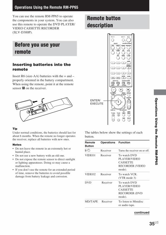
You can use the remote RM-PP65 to operatethe components in your system. You can alsouse this remote to operate the DVD PLAYER/VIDEO CASSETTE RECORDER(SLV-D300P).
Before you use yourremote
Inserting batteries into theremote
Insert R6 (size-AA) batteries with the + and –properly oriented in the battery compartment.When using the remote, point it at the remotesensor g on the receiver.
TipUnder normal conditions, the batteries should last forabout 6 months. When the remote no longer operatesthe receiver, replace all batteries with new ones.
Notes• Do not leave the remote in an extremely hot or
humid place.• Do not use a new battery with an old one.• Do not expose the remote sensor to direct sunlight
or lighting apparatuses. Doing so may cause amalfunction.
• If you don’t use the remote for an extended periodof time, remove the batteries to avoid possibledamage from battery leakage and corrosion.
Remote buttondescription
H X
. >
0/10 >10/11 12
Mm
DVD VIDEO1
SYSTEM STANDBYSELECT
TV ?/1 AV ?/1
VIDEO2 MD/TAPE
CD TUNER 2CH A.F.D.
ANT MODE T.TONE
TOP MENU/GUIDE
MUTING
MASTERVOL
DISPLAY
TV VOL TV CH
WIDE SET UP
TV/VIDEO
MAINMENU
RETURN/EXIT
SCAN/SLOW y
SHIFT ANT D.TUNING
1 2 3
4 5 6
7 8 9
ENTER CLEAR
AUDIO
PRESET/CH/D.SKIP
x
?/1
Of
F
G g
MENU/AV MENU
Operations Using the Remote RM-PP65
The tables below show the settings of eachbutton.
Remote Operations FunctionButton
?/1 Receiver Turns the receiver on or off.
VIDEO1 Receiver To watch DVDPLAYER/VIDEOCASSETTERECORDER (VIDEOmode).
VIDEO2 Receiver To watch VCR.(VTR mode 3)
DVD Receiver To watch DVDPLAYER/VIDEOCASSETTERECORDER (DVDmode).
MD/TAPE Receiver To listen to Minidiscor audio tape.
ENTER/EXECUTE
continued

36US
HT-DDW650 4-244-183-71(1) US
Remote Button Description(continued)
Remote Operations FunctionButton
CD Receiver To listen to compact disc.
TUNER Receiver To listen to radioprograms.
2CH Receiver Selects 2CH ST. mode.
A.F.D. Receiver Selects A.F.D. AUTO,DOLBY PL, PLII MOVand PLII MUS.
MODE Receiver Selects C.ST.EX A,C.ST.EX B andC.ST.EX C, HALL,JAZZ and CONCERT.
T.TONE Receiver Press to output test tone.
SHIFT Receiver Press repeatedly to selecta memory page forpresetting radio stationsor tuning to presetstations.
D.TUNING Receiver Tuner station direct key-in-mode.
MUTING Receiver Mutes the sound from thereceiver.
V/v Receiver Select a menu item.
B/b Receiver Makes adjustment orchange the setting.
MASTER Receiver Adjusts the masterVOL +/– volume of the receiver.
MAIN Receiver Press this buttonMENU repeatedly to select one
of the four cursor modes:SET UP, LEVEL, TONEand NAME.
SET UP DVD PLAYER/ Select the SETUPVIDEO MENU.CASSETTERECORDER
AV ?/1 TV/ Turns the audio andCD player/ video components on orDVD PLAYER/ off.VIDEOCASSETTERECORDER/MD deck
Remote Operations FunctionButton
SYSTEM Receiver/ Turns off the receiverSTANDBY TV/ and other Sony audio/(Press Satellite tuner/ video components.AV ?/1 CD player/and ?/1 DVD PLAYER/at the VIDEOsame time) CASSETTE
RECORDER/MD deck
1–9 and Receiver Use with “SHIFT”0/10 button to preset radio
station or tuning topreset stations and with“D.TUNING” for directtuning.
CD player/ Select track numbers.MD deck 0/10 selects track 10.
TV/ Select channel numbers.DVD PLAYER/VIDEOCASSETTERECORDER(VIDEO mode)/Satellite tuner
>10/11 CD player/ Select track numbersMD deck/ over 10.Tape deck
AUDIO TV/ Changes the sound toDVD PLAYER/ Multiplex, Bilingual orVIDEO Multi channel TVCASSETTE Sound.RECORDER
PRESET/ Receiver Scans and selectsCH/ preset stations.D.SKIP +/– TV/ Selects preset channels.
DVD PLAYER/VIDEOCASSETTERECORDER(VIDEO mode)/Satellite tuner
CD player/ Skips discs (multi-discDVD PLAYER/ changer only).VIDEOCASSETTERECORDER(DVD mode)/MD deck

Op
era
tion
s Usin
g th
e R
em
ote
RM
-PP
65
37US
HT-DDW650 4-244-183-71(1) US
Remote Operations FunctionButton
ENTER TV/ After selecting aDVD PLAYER/ channel, disc or trackVIDEO using the numericCASSETTE buttons, press to enterRECORDER the value.(VIDEO mode)/Satellite tuner/MD deck/Tape deck
ANT DVD PLAYER/ Selects output signalVIDEO from aerial terminal:CASSETTE TV signal or VCRRECORDER program.(VIDEO mode)
./> CD player/ Skips tracks.DVD PLAYER/VIDEOCASSETTERECORDER/MD deck/Tape deck
m/M CD player/ Searches tracksDVD PLAYER/ (forward orVIDEO backward).CASSETTERECORDER(DVD mode)/MD deck
DVD PLAYER/ Fastforwards orVIDEO rewinds.CASSETTERECORDER(VIDEO mode)/Tape deck
N CD player/ Starts play.DVD PLAYER/VIDEOCASSETTERECORDER/MD deck/Tape deck
X CD player/ Pauses play or record.DVD PLAYER/ (Also starts recordingVIDEO with components inCASSETTE record standby.)RECORDER/MD deck/Tape deck
Remote Operations FunctionButton
x CD player/ Stops play.DVD PLAYER/VIDEOCASSETTERECORDER/MD deck/Tape deck
DISPLAY TV/ Selects informationDVD PLAYER/ displayed on the TVVIDEO screen.CASSETTERECORDER
RETURN/ DVD PLAYER/ Returns to the previousEXIT VIDEO menu.
CASSETTERECORDER(DVD mode)
Satellite Exits the menu.tuner
CLEAR DVD PLAYER/ Press if you made aVIDEO mistake when you pressCASSETTE the number button orRECORDER press to return to the(DVD mode) continuous play etc.
SHUTTLE DVD PLAYER/ Change the playbackVIDEO speed.CASSETTERECORDER
SCAN/ DVD PLAYER/ Play in slow motion.SLOW y VIDEO
CASSETTERECORDER
TOP MENU/ DVD PLAYER/ Displays DVD title.GUIDE VIDEO
CASSETTERECORDER(DVD mode)
Satellite tuner Displays guide menu.
MENU/ Satellite tuner/ Displays menu.AV MENU DVD PLAYER/
VIDEOCASSETTERECORDER
continued

38US
HT-DDW650 4-244-183-71(1) US
Remote Operations FunctionButton
O DVD PLAYER/ Returns to the previousVIDEO menu or exits the menu.CASSETTERECORDER(DVD mode)
V/v/B/b Satellite tuner/ Selects a menu item.DVD PLAYER/VIDEOCASSETTERECORDER
ENTER/ Satellite tuner/ Press to enter theEXECUTE DVD PLAYER/ selection.
VIDEOCASSETTERECORDER
TV ?/1 TV Turns the TV on or off.
TV VOL TV Adjust the volume of+/– the TV.
TV CH +/– TV Select preset TVchannels.
TV/ TV Selects input signal: TVVIDEO input or video input.
WIDE TV Selects the wide picturemode.
Notes• Some functions explained in this section may not
work depending on the model of the receiver.• The above explanation is intended to serve as an
example only. Therefore, depending on thecomponent the above operation may not be possibleor may operate differently than described.
• Press MAIN MENU on the remote before you usethe V/v/B/b buttons for receiver operation.
• Press TOP MENU/GUIDE or MENU/AV MENUon the remote before you use the remote to controlthe satellite tuner and DVD PLAYER/VIDEOCASSETTE RECORDER.
• The >10/11 and 12 functions are not avaiable for setoperation.
Changing the factorysetting of an inputselector button
If the factory settings of the input selectorbuttons do not match your system components,you can change them. For example, if you havea tape deck and you do not have an MD deck,you can assign the MD/TAPE button to yourtape deck.Note that the settings of the DVD and VIDEO1button cannot be changed.
1 Hold down the input selector buttonwhose input source you want to change(for example, MD/TAPE).
2 Press the corresponding numericcodes of the component you want toassign to the input selector button (forexample, 25 – Tape deck B).The following numeric codes are assignedto select the input source:
To operate Code(s)
CD player 22
MD deck 23
Tape deck A 24
Tape deck B 25
VCR (command mode VTR 2*) 26
VCR (command mode VTR 3*) 27
TV (SONY) 01
DSS (Digital Satellite Receiver) 30
DVD 21
Tuner 28 or 29
* Sony VCRs are operated with a VTR 2 or 3setting. These correspond to 8mm and VHSrespectively.
Now you can use the MD/TAPE button tocontrol the Tape Deck B.
Remote Button Description(continued)

Op
era
tion
s Usin
g th
e R
em
ote
RM
-PP
65
39US
HT-DDW650 4-244-183-71(1) US
To reset a button to its factorysettingRepeat the above procedure.
To reset all the input selectorbuttons to their factory settingPress ?/1, AV ?/1 and MASTER VOL – atthe same time.
Controlling other TVs withthe remote commander
The remote commander is pre-programmed tocontrol non-Sony TVs. If your TV is listed inthe following table, set the appropriatemanufacturer’s code number.
1 Hold down TV ?/1 and enter your TV’scode number using the number buttons.Then release TV ?/1.Now you can use the TV ?/1, VOL +/–,CH +/–, TV/VIDEO and WIDE buttons tocontrol your TV.
Code numbers of controllable TVsIf there is more than one code number listed,try entering them one at a time until you findthe one that works with your TV.
TV Maker Code(s)
SONY 01
AKAI 04
AOC 04
CENTURION 12
CORONADO 03
CURTIS-MATHES 12
DAYTRON 12
EMERSON 03, 04, 14
FISHER 11
GENERAL ELECTRIC 06, 10
GOLD STAR 03, 04, 17
HITACHI 02, 03
J.C.PENNEY 04, 12
JVC 09
KMC 03
MAGNAVOX 03, 08, 12
MARANTZ 04, 13
MGA/MITSUBISHI 04, 12, 13, 17
NEC 04, 12
PANASONIC 06, 19
PHILCO 03, 04
PHILIPS 08
PIONEER 16
PORTLAND 03
QUASAR 06, 18
RADIO SHACK 05, 14
RCA 04, 10
SAMPO 12
SANYO 11
SCOTT 12
SEARS 07, 10, 11
SHARP 03, 05, 18
SYLVANIA 08, 12
TEKNIKA 03, 08, 14
TOSHIBA 07
WARDS 03, 04, 12
YORX 12
ZENITH 15
Notes• If you enter a new code number, the code number
previously entered will be erased.• When you replace the batteries of the remote
commander, the code number may change. Set theappropriate code number every time you replace thebatteries.

40US
HT-DDW650 4-244-183-71(1) US
Additional InformationIf you encounter color irregularity on a nearbyTV screen
This speaker system is magnetically shielded toallow it to be installed near a TV set. However,color irregularities may still be observed on certaintypes of TV sets.
If color irregularity is observed...
Turn off the TV set once, then turn it on again after15 to 30 minutes.
If color irregularity is observed again...
Place the speaker further away from the TV set.
If howling occurs
Reposition the speakers or turn down the volumeon the receiver.
On cleaningClean the cabinet, panel and controls with a soft clothslightly moistened with a mild detergent solution. Donot use any type of abrasive pad, scouring powder orsolvent such as alcohol or benzine.
If you have any question or problem concerning yourreceiver, please consult your nearest Sony dealer.
TroubleshootingIf you experience any of the followingdifficulties while using the receiver, use thistroubleshooting guide to help you remedy theproblem. Also, see “Checking the connections”on page 20 to verify that the connections arecorrect.
There is no sound or only a very low-level soundno matter which component is selected.
• Check that the speakers and components areconnected securely and correctly.
• Check that both the receiver and all thecomponents are turned on.
• Check that the MASTER VOLUME control isnot set at “VOL MIN”.
• Press MUTING on the remote to cancel themuting function.
• Check that the headphones are not connected.• The protective device on the receiver has been
activated because of a short circuit (“PROTECT”flashes). Turn off the receiver, eliminate theshort-circuit problem and turn on the poweragain.
Precautions
On safetyShould any solid object or liquid fall into the cabinet,unplug the receiver and have it checked by qualifiedpersonnel before operating it any further.
On power sources• Before operating the unit, check that the operating
voltage is identical with your local power supply.The operating voltage is indicated on the nameplateat the rear of the receiver.
• The unit is not disconnected from the AC powersource (mains) as long as it is connected to the walloutlet, even if the receiver itself has been turned off.
• If you are not going to use the receiver for a longtime, be sure to disconnect the receiver from thewall outlet. To disconnect the AC power cord,grasp the plug itself; never pull the cord.
• One blade of the plug is wider than the other for thepurpose of safety and will fit into the wall outletonly one way. If you are unable to insert the plugfully into the outlet, contact your dealer.
• AC power cord must be changed only at thequalified service shop.
On heat buildupAlthough the unit heats up during operation, this isnot a malfunction. If you continuously use this unit ata large volume, the cabinet temperature of the top,side and bottom rises considerably. To avoid burningyourself, do not touch the cabinet.
On placement• Place the receiver in a location with adequate
ventilation to prevent heat buildup and prolong thelife of the receiver.
• Do not place the receiver near heat sources, or in aplace subject to direct sunlight, excessive dust ormechanical shock.
• Do not place anything on top of the cabinet thatmight block the ventilation holes and causemalfunctions.
• Use caution when placing the unit or speakers onsurfaces that have been specially treated (with wax,oil, polish, etc.) as staining or discoloration of thesurface may result.
On operationBefore connecting other components, be sure to turnoff and unplug the receiver.

Ad
ditio
na
l Info
rma
tion
41US
HT-DDW650 4-244-183-71(1) US
There is no sound from a specific component.
• Check that the component is connected correctlyto the audio input jacks for that component.
• Check that the cord(s) used for the connection is(are) fully inserted into the jacks on both thereceiver and the component.
• Check that you have selected the correctcomponent on the receiver.
There is no sound from one of the frontspeakers.
Connect a pair of headphones to the PHONES jackto verify that sound is output from the headphones(page 21).If only one channel is output from the headphones,the component may not be connected to thereceiver correctly. Check that all the cords are fullyinserted into the jacks on both the receiver and thecomponent.If both channels are output from the headphones,the front speaker may not be connected to thereceiver correctly. Check the connection of thefront speaker which is not outputting any sound.
The left and right sounds are unbalanced orreversed.
• Check that the speakers and components areconnected correctly and securely.
• Adjust balance parameters in the LEVEL menu.
There is severe hum or noise.
• Check that the speakers and components areconnected securely.
• Check that the connecting cords are away from atransformer or motor, and at least 3 meters awayfrom a TV set or fluorescent light.
• Move your TV away from the audio components.• The plugs and jacks are dirty. Wipe them with a
cloth slightly moistened with alcohol.
There is no sound or only a very low-level soundis heard from the center or / and surroundspeaker.
• Make sure the sound field function is on (pressMOVIE or MUSIC).
• Select a sound field containing the word“C.ST.EX” (pages 24).
• Adjust the speaker level (page 19).• Make sure the center or/and surround speaker
size parameter is set to either “SMALL” or“LARGE” (page 18).
There is no sound from the active sub woofer.
• Check that the sub woofer is connected correctlyand securely.
• There is no sound output from the SUBWOOFER terminal depending on the sound field(page 47).
The surround effect cannot be obtained.
Make sure the sound field function is on (pressMOVIE or MUSIC).
Dolby Digital or DTS multi channel sound is notreproduced.
• Check that the playing DVD, etc. is recorded inDolby Digital or DTS format.
• When connecting the DVD player, etc. to thedigital input jacks of this receiver, check theaudio setting (settings for the audio output) of theconnected component.
Recording cannot be done.
• Check that the components are connectedcorrectly.
• Select the source component with input selectorbutton.
• Make sure that INPUT MODE is set to“ANALOG” (page 21) before recording from adigital component connected to the analogMD/TAPE terminal.
continued
42US
HT-DDW650 4-244-183-71(1) US
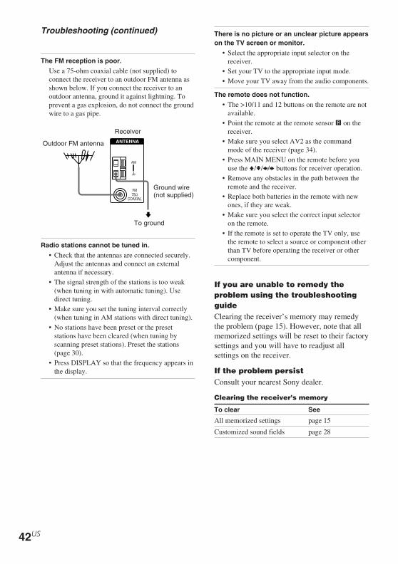
The FM reception is poor.
Use a 75-ohm coaxial cable (not supplied) toconnect the receiver to an outdoor FM antenna asshown below. If you connect the receiver to anoutdoor antenna, ground it against lightning. Toprevent a gas explosion, do not connect the groundwire to a gas pipe.
Radio stations cannot be tuned in.
• Check that the antennas are connected securely.Adjust the antennas and connect an externalantenna if necessary.
• The signal strength of the stations is too weak(when tuning in with automatic tuning). Usedirect tuning.
• Make sure you set the tuning interval correctly(when tuning in AM stations with direct tuning).
• No stations have been preset or the presetstations have been cleared (when tuning byscanning preset stations). Preset the stations(page 30).
• Press DISPLAY so that the frequency appears inthe display.
Outdoor FM antenna
Receiver
Ground wire(not supplied)
To ground
y
AM
FM75Ω
COAXIAL
ANTENNA
There is no picture or an unclear picture appearson the TV screen or monitor.
• Select the appropriate input selector on thereceiver.
• Set your TV to the appropriate input mode.• Move your TV away from the audio components.
The remote does not function.
• The >10/11 and 12 buttons on the remote are notavailable.
• Point the remote at the remote sensor g on thereceiver.
• Make sure you select AV2 as the commandmode of the receiver (page 34).
• Press MAIN MENU on the remote before youuse the V/v/B/b buttons for receiver operation.
• Remove any obstacles in the path between theremote and the receiver.
• Replace both batteries in the remote with newones, if they are weak.
• Make sure you select the correct input selectoron the remote.
• If the remote is set to operate the TV only, usethe remote to select a source or component otherthan TV before operating the receiver or othercomponent.
If you are unable to remedy theproblem using the troubleshootingguideClearing the receiver’s memory may remedythe problem (page 15). However, note that allmemorized settings will be reset to their factorysettings and you will have to readjust allsettings on the receiver.
If the problem persistConsult your nearest Sony dealer.
Clearing the receiver’s memory
To clear See
All memorized settings page 15
Customized sound fields page 28
Troubleshooting (continued)

Ad
ditio
na
l Info
rma
tion
43US
HT-DDW650 4-244-183-71(1) US
Sensitivity: –Impedance: 75 ohmsS/N: 100 dB(A, 20 kHz LPF)
Sensitivity: –Impedance: –S/N: 100 dB(A, 20 kHz LPF)
Inputs (Digital)
DVD (Coaxial)
VIDEO 2 (Optical)
Outputs
MD/TAPE (OUT),VIDEO 1(AUDIO OUT)
SUB WOOFER
ToneGain levels: ±6 dB, 1 dB step
FM tuner sectionTuning range 87.5 - 108.0 MHz
Antenna terminals 75 ohms, unbalanced
Intermediate Frequency10.7 MHz
SensitivityMono: 18.3 dBf, 2.2 µV/75 ohmsStereo: 38.3 dBf, 22.5 µV/75 ohms
Usable sensitivity 11.2 dBf, 1 µV/75 ohms
S/NMono: 76 dBStereo: 70 dB
Harmonic distortion at 1 kHzMono: 0.3%Stereo: 0.5%
Separation 45 dB at 1 kHz
Frequency response 30 Hz – 15 kHz,+0.5/–2 dB
Selectivity 60 dB at 400 kHz
10 Hz – 50 kHz+0.5/–2 dB (with soundfield and tone bypassed)
Sensitivity: 500 mVImpedance: 50 kilohmsS/N2): 96 dB(A, 500 mV3))
Voltage: 500 mVImpedance: 10 kilohms
Voltage: 2 VImpedance: 1 kilohms
Specifications
AUDIO POWER SPECIFICATIONS
POWER OUTPUT AND TOTALHARMONIC DISTORTION:
With 8 ohm loads, both channels driven, from40 – 20,000 Hz; rated 70 watts per channelminimum RMS power, with no more than0.7 % total harmonic distortion from 250milliwatts to rated output.
Amplifier sectionPOWER OUTPUTRated Power Output at Stereo Mode(8 ohms 40 Hz – 20 kHz, THD 0.7 %)STR-K650P: 70 W + 70 W
Reference Power Output(8 ohms 1 kHz, THD 0.7 %)STR-K650P: FRONT1):80 W/ch
CENTER1): 80 WSURR1): 80 W/ch
1) Depending on the sound field settings and thesource, there may be no sound output.
Frequency response
CD, MD/TAPE, DVD,VIDEO 1, 2
Inputs (Analog)
CD, MD/TAPE, DVD,VIDEO 1, 2
2) INPUT SHORT (with sound field and tonebypassed).
3) Weighted network, input level.
continued

44US
HT-DDW650 4-244-183-71(1) US
Specifications (continued)
AM tuner sectionTuning rangeWith 10-kHz tuning scale: 530 – 1710 kHz4)
With 9-kHz tuning scale: 531 – 1710 kHz4)
Antenna Loop antenna
Intermediate Frequency450 kHz
Usable sensitivity 50 dB/m (at 1,000 kHz or999 kHz)
S/N 54 dB (at 50 mV/m)
Harmonic distortion 0.5 % (50 mV/m, 400 Hz)
SelectivityAt 9 kHz: 35 dBAt 10 kHz: 40 dB
4) You can change the AM tuning scale to 9 kHz or10 kHz. After tuning in any AM station, turn offthe receiver. Hold down PRESET TUNING + andpress ?/1. All preset stations will be erased whenyou change the tuning scale. To reset the scale to10 kHz (or 9 kHz), repeat the procedure.
Video sectionInputsVideo: 1 Vp-p, 75 ohms
OutputsVideo: 1 Vp-p, 75 ohms
GeneralPower requirements 120 V AC, 60 Hz
Power consumption 175 W
Power consumption (during standby mode)0.3 W
Dimensions 16 7/8 × 5 6/8 × 11 6/8inches includingprojecting parts andcontrols
Mass (Approx.) 15 lb 14 oz
Speaker section
SS-MSP75 for front and surround speakersSS-CNP75 for center speakerSpeaker system Full range, magnetically
shielded
Speaker units 70 mm × 100 mm conetype
Enclosure type Bass reflex
Rated Impedance 8 ohms
Power handling capacity (Maximum inputpower)
100 W
Sensitivity level 86 dB (1 W, 1 m)
Frequency range 160 Hz – 20,000 Hz
Dimensions (w/h/d)SS-MSP75 Approx. 3 5/8 × 6 × 5
inchesSS-CNP75 Approx. 9 1/8 × 3 5/8 × 5
inchesMassSS-MSP75 1 lb 13 ozSS-CNP75 2 lb 4 oz
SA-WMSP85 for sub woofer
AUDIO POWER SPECIFICATIONS
POWER OUTPUT AND TOTALHARMONIC DISTORTION:
With 6 ohm loads, from 28 – 200 Hz;rated 100 watts, minimum RMS power, with nomore than 0.8% total harmonic distortion from250 milliwatts to rated output.Speaker system Active subwoofer,
magnetically shielded
Speaker unit Woofer: 20 cm cone type
Enclosure type Acoustically loaded bassreflex

Ad
ditio
na
l Info
rma
tion
45US
HT-DDW650 4-244-183-71(1) US
Continuous RMS power output(6 ohms, 20 – 250 Hz)
100 W
Reproduction frequency range28 Hz – 200 Hz
High frequency cut-off frequency150 Hz
Input LINE IN (input pin jacks)
Power requirements 120 V AC, 60 Hz
Power consumption 100 W
Dimensions (w/h/d) Approx. 10 3/4 × 12 7/8 ×15 3/4 inches includingfront panel
Mass 22 lb 1 oz
Supplied accessoriesFM wire antenna (1)AM loop antenna (1)Speaker connecting cord, long (2)Speaker connecting cord, short (3)Monaural connecting cord (1 phono to 1 phono) (1)Audio cord (1)Video cord (1)Coaxial digital cord (1)Foot pads (speakers) (20)Foot pads (subwoofer) (4)Remote commander (1)R6 (size -AA) batteries (2)Speakers
• Front speakers (2)• Surround speakers (2)• Center speaker (1)• Sub woofer (1)
For details on the area code of the component youare using, see page 4.
Design and specifications are subject to changewithout notice.

46US
HT-DDW650 4-244-183-71(1) US
Tables of settings using the MAIN MENU button
You can make various settings using the MAIN MENU, MENU / and MENU +/– buttons. Thetables below show each of the settings that these buttons can make.
Press MAIN MENU Press MENU or MENU Press MENU + or MENU – to select Pagerepeatedly to select to select
LEVEL L R BAL. L/R XX L +8 to R +8 (1 steps) 27
CTR XXX dB –10 dB to +10 dB (1 dB steps)
SUR.L. XXX dB –10 dB to +10 dB (1 dB steps)
SUR.R. XXX dB –10 dB to +10 dB (1 dB steps)
S.W. XXX dB –10 dB to +10 dB (1 dB steps)
D. RANGE COMP. XXX OFF, STD, MAX
EFCT. XXX depends on the sound field(MIN, STD, MAX)
SET UP SW (SUB WOOFER) S.W. XXX1) YES, NO 16
L R (FRONT) XXXXX1) LARGE, SMALL
C (CENTER) XXXXX1) LARGE, SMALL, NO
SL SR (SURROUND) XXXXX1) LARGE, SMALL, NO
L R DIST. XX ft. between 3 feet and 23 feet (1 foot steps)
C DIST. XX ft. between L R DIST. and 5 feet(1 foot steps)
SL SR DIST. XX ft. between L R DIST. and 15 feet(1 foot steps)
SL SR PL. XXXX LOW, HIGH
DEC. XXXX AUTO, PCM 33
TONE BASS XX dB –6 dB to +6 dB (1 dB step) 28
TREB. XX dB –6 dB to +6 dB (1 dB step)
1) Only when you select “NORM. SP.”

Ad
ditio
na
l Info
rma
tion
47US
HT-DDW650 4-244-183-71(1) US
< LEVEL >
FRONT CENTER SUR.L. SUR.R. S.W. D.RANGE EFCT.BAL LEVEL LEVEL LEVEL LEVEL COMP1) LEVEL
2CH ST. z z
A.F.D. AUTO z z z z z z
DOLBY PL z z z z z z
PLII MOV z z z z z z
PLII MUS z z z z z z
C.ST.EX A z z z z z z z
C.ST.EX B z z z z z z z
C.ST.EX C z z z z z z z
HALL z z z z z2) z z
JAZZ z z z z z2) z z
CONCERT z z z z z2) z z
PCM 96K z
1) These parameters may not operate depending on the source or adjustments. For details, see each item in“Adjusting the level parameters” (page 27).
2) When these sound fields are selected, there is no sound output from the sub woofer if the front speaker size isset to “LARGE”. However, sound will be output from the sub woofer if the digital input signal contains LFEsignals.
< TONE >
BASS TREB.
2CH ST. z z
A.F.D. AUTO z z
DOLBY PL z z
PLII MOV z z
PLII MUS z z
C.ST.EX A z z
C.ST.EX B z z
C.ST.EX C z z
HALL z z
JAZZ z z
CONCERT z z
PCM 96K
The adjusted LEVEL parameters are applied to all the sound fields except for EFCT. parameter. ForEFCT. parameter, the settings are stored individually for each sound field.
Adjustable parameters for each sound fieldThe adjusted BASS and TREB. parameters are applied to all sound fields.

48US
HT-DDW650 4-244-183-71(1) US
Sony Corporation Printed in Malaysia