home power - schatz energy research center
TRANSCRIPT

THE HANDS-ON JOURNAL OF HOME-MADE POWER
HOME POWER
10 Doing Their Part
After ten years off the grid,Humboldt State University’sCampus Center forAppropriate Technologyswitched to 2.4 KW of utility-intertied PV. Now they’re amodel for decentralizedgeneration—pitching theirgreen energy into the mix.
50 Wind Genny Comparison
Wind guru Mick Sagrillo hascompiled his fourth “Apples& Oranges” article to helpyou choose a home-sizedwind generator.
24 Efficient Computing &Wireless Internet
John Bertrand shares hishomework on finding anenergy efficient laptop thatdoesn’t work his RE systemtoo hard. His off-grid,wireless Internet and LANsystem is pretty slick too—check it out!
32 Small & Mobile PV System
A one-module PV systemwas just the ticket for PhillipAngell to get into renewableenergy. He put it on a trailer,and now he’s got power togo—anywhere the job takeshim.
Features
Issue #90 August / September 2002
Solar Thermal
86 Passive Solar Basics
Plug in these passive solarprinciples for a beautiful,energy efficient home. KenOlson and Joe Schwartz tellyou how to design a housethat will keep you warm,save you money, andimpress your neighbors!
More Features
Homebrew
40 LED Flashlight Conversion
Turn your Mini Maglite into amighty flashlight. Thishomebrew makes it mightystout, bright, and radicallyextends battery life.
98 Build Your Own Antenna
Lock onto radio signals froma remote site by buildingyour own antenna—BillLayman tells us how.
46 PVs vs. SUVs
Is your money going downthe road, or in your pocket?Look at this cost comparisonand ask yourself, “Is PV tooexpensive?”
72 Shakespearean Solar?
Brian Underwood reads thebard while tending his PV“volt garden.” He learned alot about RE by tinkeringwith his small systems.

Access DataHome Power
PO Box 520Ashland, OR 97520 USA
Subscriptions and Back Issues:800-707-6585 VISA, MCDiscover, & American Express541-512-0201 Outside USA
Advertising: Phone: 800-707-6585 or 541-512-0201 Outside USAFax: 541-512-0343
E-mail: [email protected]: www.homepower.com
Paper and Ink DataCover paper is Aero Gloss, a 100#, 10%recycled (postconsumer-waste), elementalchlorine-free paper, manufactured bySappi Fine Paper.
Interior paper is Ultra LWC Glossy, a 45#,100% postconsumer-waste, totallychlorine-free paper, manufactured byLeipa, an environmentally responsible millbased in Schwedt, Germany.
Printed using low VOC vegetable-basedinks.
Printed by
St. Croix Press, Inc., New Richmond, WI
Legal
Home Power (ISSN 1050-2416) ispublished bi-monthly for $22.50 per yearat PO Box 520, Ashland, OR 97520.International surface subscription forUS$30. Periodicals postage paid atAshland, OR, and at additional mailingoffices. POSTMASTER send addresscorrections to Home Power, PO Box 520,Ashland, OR 97520.
Copyright ©2002 Home Power, Inc.
All rights reserved. Contents may not bereprinted or otherwise reproduced withoutwritten permission.
While Home Power magazine strives forclarity and accuracy, we assume noresponsibility or liability for the use of thisinformation.
Regulars
Access and Info
This paper is recycled and recycleable.
8 From Us to You
80 HP’s Subscription Form
81 Home Power’s Biz Page
142 Happenings—RE Events
146 Letters to Home Power
156 Q&A
158 MicroAds
160 Index to Advertisers
Cover: Some of the thirteen home-scale wind generators compared in “Apples & Oranges” on page 50.
More Columns
Columns
124 Word Power
Electrons defined—IanWoofenden helps us get agrasp on those bouncing,invisible particles.
GoPower
112 Juicin’ Up Your EV
Part II on EV charging.
120 Is That Used EV a Bargain?
Part II on buying a used EV.
Guerrilla Solar
Book Review
123 Shelter Sketchbook
Richard Engel reviews aninspirational design book.
Things that Work!106 Glowing Reviews
These luminescent stripsdon’t use electricity to lightup your life.
116 A Meter That Measures Up
Joe Schwartz deems thiswatt-hour meter “for real” inmeasuring electrical loads.
82 Guerrilla 0021
This guerrilla group is out ofthe closet in Spain andpushing for change.
126 Not In My (Global) Backyard
Edison International wants tobuild a dirty, coal-fired powerplant in Thailand’s ecologicallysensitive Prachuap province.
130 Independent PowerProviders
Don Loweburg looks back atbuydown programs and intothe future of inverters.
134 Code Corner
More grid connection details.
138 Home and Heart
Kathleen is quite the ham—radio operator, that is.
144 The Wizard
Magnetic energy’s potential.
154 Ozonal Notes
Richard thinks he’s GeorgeJetson. And by the way,check out HP’s new Web site!

Jim Zoellick & Andrew Posner ©2002 Jim Zoellick & Andrew Posner©2002 Jim Zoellick & Andrew Posner
10 Home Power #90 • August / September 2002
n May of 1991, students at theCampus Center for AppropriateTechnology (CCAT) at Humboldt
State University (HSU) cut the wireconnecting them to Pacific Gas andElectric Company (PG&E), their localelectric utility. For ten years, CCATdemonstrated energy self-sufficiency bygetting the majority of its electricity fromsun and wind. To supplement therenewable resources, they producedelectricity using a backup generatorrunning on biodiesel fuel made on-sitewith waste oil from local restaurants. InJune 2001, after ten years of energyindependence, we reconnected toPG&E.
Why the change? We are now demonstrating a state-of-the-art, grid-connected photovoltaic system. Althoughsolar-electric systems are more cost competitive inremote applications where grid electricity is notavailable, the majority of us are connected to the utilitygrid. When you’re on the grid, batteryless PV systemsare the most efficient and cost effective strategy. Bydemonstrating such a system, CCAT now has theopportunity to reach a much larger audience ofprospective PV system adopters.
Over 3,200 people visit CCAT every year, either on self-guided or docent-led tours. The home and grounds areopen six days a week to students and the community.Besides the renewable electricity generation equipment,some of the systems featured at CCAT include solar hotwater, solar ovens, pedal-powered appliances, organicgardens, a solar greenhouse, vermicomposting,greywater recycling, a composting toilet, and straw baleconstruction.
Like other systems at CCAT, the PV system has beendesigned as a demonstration, accessible to our visitors.We track our electrical energy use and PV production,and document this data using a dry erase board that is
Jim Zoellick & Andrew Posner
Humboldt State University's Campus Center for Appropriate Technology wanted to create a model for small-scale,distributed electricity generation. After ten years of off-grid living, they reconnected to the utility grid.

PV System
11Home Power #90 • August / September 2002
updated weekly. From October 17, 2001 through April23, 2002, the new PV system generated 901 KWH ofclean electricity. In the future, we plan to have a smallelectronic display that will show real time data on thehouse electrical demand and PV system output, as wellas weekly totals.
The Old Stand-Alone SystemThe old stand-alone PV system at CCAT consisted of22 Solec International photovoltaic panels, a Whisperwind turbine, and a backup generator. The PVs weredonated in the 1980s from the Flat Plate Array Projectat the Jet Propulsion Lab.
The output from the 22 panel array was about 700 wattspeak on a sunny summer day. The Whisper H500 windturbine, standing 43 feet (13 m) tall and using a WorldPower control box, generated very little, due to the site’spoor wind energy potential. Part of the problem was thatthe surrounding trees had grown considerably since theoriginal wind generator was first installed on that towerin 1984.
Energy generated during the day was stored in a 24 voltbattery bank consisting of twelve, Trojan L-16 batteries.A Trace C40 charge controller regulated the batteryvoltage during charging. Twelve volt DC loads weresupplied via a Vanner battery equalizer, and AC loadswere supplied using a Trace SW4024 inverter. Abiodiesel engine generator was used to charge thebattery bank as needed.
The solar-electric modules from the old system are nowbeing used for learning opportunities at CCAT. Studentsin a variety of classes and workshops will have achance to wire up the panels and test their output. Thepanels that are still performing well will be used forfuture projects.
The New Grid-Connected SystemDesign of the new system wascentered around a generousdonation of eight, large area (4 x 6foot; 1.2 x 1.8 m) modules from ASEAmericas, Inc. The modules, modelnumber ASE-300-DGF/17, are eachrated at 300 W at standard testconditions (STC). STC are anirradiance of 1,000 watts per squaremeter, and a cell temperature of25°C (77°F).
These are 12 volt nominal modules,with a rated maximum power pointvoltage of 17.2 V. Four of thesemodules wired in series create aroughly 1 KW, 48 V building block fora grid-connected system (derated by
12 percent from STC rating to better represent PVoutput under normal operating conditions at ourlocation). We planned to use two series strings of fourmodules each, giving us a 48 V, 2 KW system.
The first and biggest design decision was to choose aninverter for the system. CCAT already owned a TraceSW4024 inverter that had been used in the stand-alonePV system, so obviously we considered this as a primecandidate. It is rated for grid-tied applications, and hasmore than enough capacity to handle the total ratedarray output of 2,400 W.
However, most Trace SW series inverters require atleast a small battery bank. We wanted to put in a systemthat set a good example for other potential grid-connected PV adopters. Unless you have a serious
Stick a meter on those PVs! Checking out the 300 watt ASE PV modules.
The installation crew gained some hands-on experience as they learned about utility-interactive PV systems.

PV System
12 Home Power #90 • August / September 2002
need for backup power (you really have some criticalloads), it doesn’t make any sense to install a grid-connected system with battery backup.
Batteries complicate PV systems. They add significantlyto system cost. They need to be maintained regularlyand replaced periodically. And they add significantinefficiencies to the system. In most places, the grid isnot down very often or for very long, so batteries add nobenefit most of the time.
After speaking with an engineer at Trace, and studyingthe capabilities of the Trace SW4024, including theadjustable software settings such as float voltage, sellmode voltage, and grid usage timer, we decided againstthis option. This inverter is simply not optimized for PVsystems installed in grid-connected applications. Whenthe PVs are not charging, this inverter constantly floatcharges the batteries with electricity from the grid.
At best, with a minimum sized battery bank capacity of100 AH (per Trace specifications), we expected to loseat least a few hundred watt-hours per day and perhapsas much as 1 to 2 KWH per day due to battery charging.This was simply unacceptable to us. It represented asystem efficiency loss of anywhere from 5 to 25 percent.
We did consider adding a voltage-controlled relaysystem that would connect the inverter to the grid onlywhen the PVs were charging, thereby minimizing anybattery charging from the grid. We decided against thisbecause it would complicate the system and make itless representative of a standard grid-connectedsystem. In addition, the SW4024 does not offermaximum power point tracking, and would requirecharge controllers to provide battery overchargeprotection in the event of a grid failure.
We also considered the Trace Sun Tie ST2500. This is autility-interactive inverter that does not require anybatteries. However, Trace has had some seriousproblems with the maximum power point trackingfeature in the Sun Tie series inverters. After talking toTrace and other experts in the field about the problem,we decided that we were not willing to take a risk with aTrace Sun Tie unit.
This left only one other option for a California EnergyCommission (CEC) certified utility-interactive inverterthat was configured to accept 48 VDC input. This wasthe GC-1000 manufactured by Advanced Energy. Thisinverter came highly recommended from a couple of ourindustry contacts. It is rated at 1 KW single-phase 120VAC output, features maximum power point tracking,and has a peak efficiency of 93 percent.
One of these inverters is a good match with four, 12 voltnominal ASE Americas 300 W modules wired in series,
so we chose to use two of these inverters. We contactedAdvanced Energy and they generously agreed todonate two refurbished GC-1000 inverters, along with adata monitoring system for our demonstration project.
Since the majority of our equipment was donated, wedid not apply for CEC buydown funds. However, we stilldecided to use equipment that was certified by the CEC.The Advanced Energy inverter is well accepted, and wewanted our electric utility to approve our equipmentwithout question.
New System DescriptionEach of the two inverters is independently connected tofour PV modules wired in series. The inverters arefactory-equipped with a 25 A breaker, a 30 A fuse andground-fault protection on the DC input.They have a 15 Abreaker, 15 A fuse, and surge arrestor on the AC output.
The hot legs of the two inverter AC outputs are switchedusing a PG&E approved, 30 A, double pole disconnectswitch. This is a lockable, visible disconnect switch,
Proper planning and many, many hands made for a smooth installation day.

Fuse:30 A, in rooftop
junction box
AdvancedEnergy
Inc.
AdvancedEnergy
Inc.
Inverters:Two Advanced Energy
GC-1000, 1,000 W each,48 VDC input,
120 VAC sine wave output,utility-interactive
Photovoltaics:Eight ASE-300-DGF/17 modules, 300 W each,
wired for 2,400 W at 48 VDC
AC Mains Panel:30 A breakers ininverter circuits
To Utility Grid:240 VAC
Utility’s Lockable Disconnect
Earth GroundNote: All numbers are rated, manufacturers’ specifications, or nominal unless otherwise specified.
Fuse:30 A, in rooftop
junction box
13Home Power #90 • August / September 2002
mounted alongside the main service panel next toPG&E’s meter, and meets PG&E’s interconnectionrequirements. The AC output from each inverter is wiredto a 30 A breaker in the main service panel.
The CCAT roof is conveniently oriented due south, witha slope of 26.5 degrees from horizontal. At our Arcatalatitude of 41 degrees north, the roof slope falls justwithin a recommended array slope of ±15 degrees ofour latitude. In addition, analysis of Arcata solarinsolation data (obtained from the National SolarRadiation Database) indicates that the annual amountof insolation received on a sloped surface in Arcata isnearly identical for slopes ranging from 20 to 40degrees.
With this background information, we chose to mountthe PV modules parallel to the slope of the roof, usingthe Schott Applied Power (formerly AscensionTechnology) pitched RoofJack mounting system. Ajunction box, also purchased from Schott AppliedPower, mounts to the center RoofJack. It contains 30 Afuses, and serves as a combiner box where weterminate the array leads and start our DC wire run,enclosed in conduit, to the inverters. (See the systemschematic.)
CCAT Electrical LoadsThe electrical loads at CCAT vary with the seasons. Ingeneral, energy use is higher when school is in session
due to an increase in activity. Loads include fluorescentlights, stereos, computers, power tools, and othermiscellaneous equipment. During the summer, we run aSun Frost refrigerator, while the other eight months ofthe year we use a cold box with a natural convectioncycle to keep food cold. A variety of pedal-poweredappliances, such as a TV and a blender, also help toconserve electricity.
As CCAT continues to expand and demonstratealternatives for living lightly, new energy demandssometimes arise. For example, we recently joinedefforts with the campus recycling program to greatlyreduce food waste on the HSU campus. The projectinvolves use of an electrically driven shredder thatprepares the food waste to enter an industrial-sizedvermicompost (worm) bin capable of handling up to 150pounds (68 kg) a day. The bin itself also requireselectricity to run a motorized unit that forces the finishedcompost out of the bin for collection.
Our best estimate of our itemized electrical use is in theload table. Our actual usage between October 2001 andApril 2002 averaged 1.9 KWH per day, which agreesclosely with our estimate.
Net Metering Rate OptionsAfter adjusting for an expected array operatingtemperature of 122°F (50°C) and an average inverterefficiency of 84 percent, the new grid-connected PV
PV System
14 Home Power #90 • August / September 2002
system is expected to provide approximately 1.8 KW ofpeak AC power. Given our annual average of about fourpeak sun hours per day in Arcata, we expect an averagedaily energy output of 7.2 KWH. This is well beyondCCAT’s current energy needs of 1.9 KWH per day, sothe system should produce a significant excess of solarelectricity.
The PV system is definitely oversized. It would not be acost effective design for the typical homeowner becausePG&E won’t pay for any excess electrical generation. Ifyou’re running a net metered system in California, thebest you can do is net your energy cost to zero on anannual basis and pay the utility’s minimum monthlycharge. In PG&E territory, this amounts to US$5 eachmonth. Most of our equipment was donated, so it did notcost us any extra for the excess clean solar electricitywe feed into the grid.
This results in a modest benefit to theenvironment and, inadvertently, toPG&E’s pocketbook. We’re lookingforward to the day when the utilitiesare required to pay a premium ratefor excess electricity generated usingrenewable resources. They could sellthis electricity through their greenpower programs.
Our rate options for net meteringincluded the standard residentialrate, or the residential time-of-use(TOU) rate. We considered both ofthese options. The TOU rate wouldhave required installation of a TOUmeter at a cost of US$277. Becausewe generate an excess of solarelectricity, the TOU rate will notbenefit us.
It’s a different situation for residential PG&E customerswhose electricity usage is primarily during the eveningand weekend periods (people who work during thedaytime and minimize their phantom loads). The TOUrate can allow them to install a smaller PV system andstill reduce their electricity bill to the minimum US$5service charge. This is because the TOU rate puts ahigher value on electricity used or generated during thesummer peak hours. The optimal way to minimize yourbill is to have electricity costs exactly cancel outelectricity “revenues” on an annual basis.
The summer peak period for TOU customers is May 1through October 31 from noon to 6 PM, Mondaythrough Friday. Peak usage during this period is drivenby the high cooling load in much of California. Duringthis period, the TOU rate is about US32¢ per KWH.During the winter peak period, the TOU rate is aboutUS12¢ per KWH, and during the off-peak periods it isabout US9¢ per KWH. So, if most of your energy usageis during the off-peak periods and a substantial amountof your PV electricity is generated during the peakperiods, you can significantly decrease the optimal sizeof your PV system (and the associated capital costs).
For example, we have estimated that a PV systemfacing due south at a slope of 41 degrees in Arcata willgenerate approximately 27 percent of its annual energyproduction during the summer peak period, and another17 percent during the winter peak period. Assuming youare on the TOU rate and use all of your electricity duringthe off-peak periods, this would allow you to decreasethe size of your PV array by 41 percent.
With an average daily electrical usage of 10 KWH perday on the standard rate, you would need about a 2.9
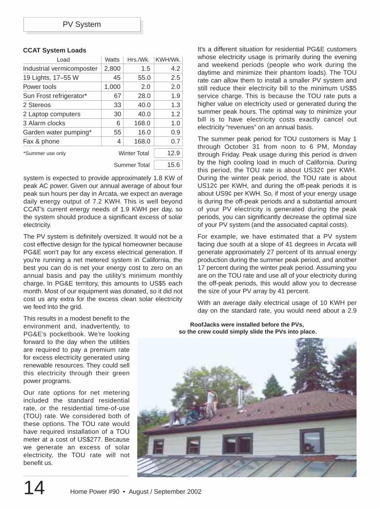
RoofJacks were installed before the PVs,so the crew could simply slide the PVs into place.
CCAT System LoadsLoad Watts Hrs./Wk. KWH/Wk.
Industrial vermicomposter 2,800 1.5 4.219 Lights, 17–55 W 45 55.0 2.5Power tools 1,000 2.0 2.0Sun Frost refrigerator* 67 28.0 1.92 Stereos 33 40.0 1.32 Laptop computers 30 40.0 1.23 Alarm clocks 6 168.0 1.0Garden water pumping* 55 16.0 0.9Fax & phone 4 168.0 0.7
Winter Total 12.9
Summer Total 15.6
*Summer use only
PV System
15Home Power #90 • August / September 2002
KW system (rated at STC) to net your electricity cost tozero and thereby lower your bill to the US$5 minimumper month. On the TOU rate, you could decrease yoursystem size to 1.7 KW, and still limit your bill to US$5per month.
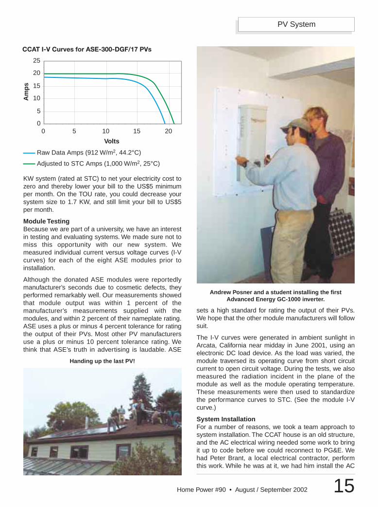
Module TestingBecause we are part of a university, we have an interestin testing and evaluating systems. We made sure not tomiss this opportunity with our new system. Wemeasured individual current versus voltage curves (I-Vcurves) for each of the eight ASE modules prior toinstallation.
Although the donated ASE modules were reportedlymanufacturer’s seconds due to cosmetic defects, theyperformed remarkably well. Our measurements showedthat module output was within 1 percent of themanufacturer’s measurements supplied with themodules, and within 2 percent of their nameplate rating.ASE uses a plus or minus 4 percent tolerance for ratingthe output of their PVs. Most other PV manufacturersuse a plus or minus 10 percent tolerance rating. Wethink that ASE’s truth in advertising is laudable. ASE
sets a high standard for rating the output of their PVs.We hope that the other module manufacturers will followsuit.
The I-V curves were generated in ambient sunlight inArcata, California near midday in June 2001, using anelectronic DC load device. As the load was varied, themodule traversed its operating curve from short circuitcurrent to open circuit voltage. During the tests, we alsomeasured the radiation incident in the plane of themodule as well as the module operating temperature.These measurements were then used to standardizethe performance curves to STC. (See the module I-Vcurve.)
System InstallationFor a number of reasons, we took a team approach tosystem installation. The CCAT house is an old structure,and the AC electrical wiring needed some work to bringit up to code before we could reconnect to PG&E. Wehad Peter Brant, a local electrical contractor, performthis work. While he was at it, we had him install the AC
Am
ps
CCAT I-V Curves for ASE-300-DGF/17 PVs
5
10
15
20
25
5 10 15 20
Volts
Raw Data Amps (912 W/m2, 44.2°C)
Adjusted to STC Amps (1,000 W/m2, 25°C)
00
Handing up the last PV!
Andrew Posner and a student installing the firstAdvanced Energy GC-1000 inverter.
PV System
16 Home Power #90 • August / September 2002
disconnect for the PV system, prepare the AC panel forinterconnection, and run the AC wiring from the inverterroom to the AC disconnect.
We had Bob-O Schultze, a solar-electric contractor, runthe DC wire and conduit, assist with the inverter and PVmodule installation, and ensure that our installation wascode compliant. We installed the array mountingstructure, PV modules, and inverters ourselves, withhelp from students in a PV Design and Installation classoffered through the Environmental ResourcesEngineering Department at HSU. The equipment wechose allowed for a rather quick and easy installationprocedure.
The RoofJack mounting system is designed for pitchedasphalt shingle roofs like CCAT’s. It supports themodules about 3 inches (7.6 cm) above and parallel tothe roof, allowing for adequate air circulation betweenthe modules and the roof to promote module cooling.The RoofJacks came complete with self-drillingfasteners (21/4 inch, #12) and sealing washers,preapplied butyl-rubber sealing pads, and pipe nipplesfor wire pass-through between modules.
Our eight, large area modules were installed in onecontinuous row. Each module is supported by fourRoofJacks, one placed near each of the module’s fourcorners. There are two types of RoofJacks—end andinterior. We used four end RoofJacks at the extremitiesof the array. A pair of shared interior RoofJacks supportthe module edges that are located next to othermodules, for a total of 14 interior RoofJacks.
To properly locate the RoofJacks on the roof, we built ajig with the bolt hole pattern for one set of RoofJacks.After installing the first set, we simply moved the jig overand installed the next set, and so on. According to themanufacturer, securing the RoofJacks directly to thesheathing (a minimum of 5/8 inch; 16 mm thickness) isadequate, but we felt that it was prudent to addreinforcement. We located the array on the roof so thatfour of the interior RoofJacks were secured directly totwo rafters. To secure the remaining RoofJacks, we
either scabbed 2 by 4 blocks to a rafter or added stripsof plywood sheathing on the underside of the roofsheathing to provide a more secure attachment.
Once the RoofJacks were installed, the modules wereoutfitted with their mounting bolts. Four bolts wereattached to each module, two on each side near thecorners. These bolts protrude about 1/2 inch (13 mm)with a sleeve. To install the modules, we simply liftedthem into place and slid the four mounting bolts intoslots on the RoofJacks.
Wiring the array was just as easy. Our system consistsof two separate subarrays, each comprised of fourmodules wired in series and connected to an inverter.The first set of four modules in the row make up onesubarray, and the second set of modules make up thesecond subarray.
We mounted the array combiner box in the center of therow of eight modules between the two arrays. This boxhouses fusing for the arrays, and provides a place to
Per
cen
t
Output Watts
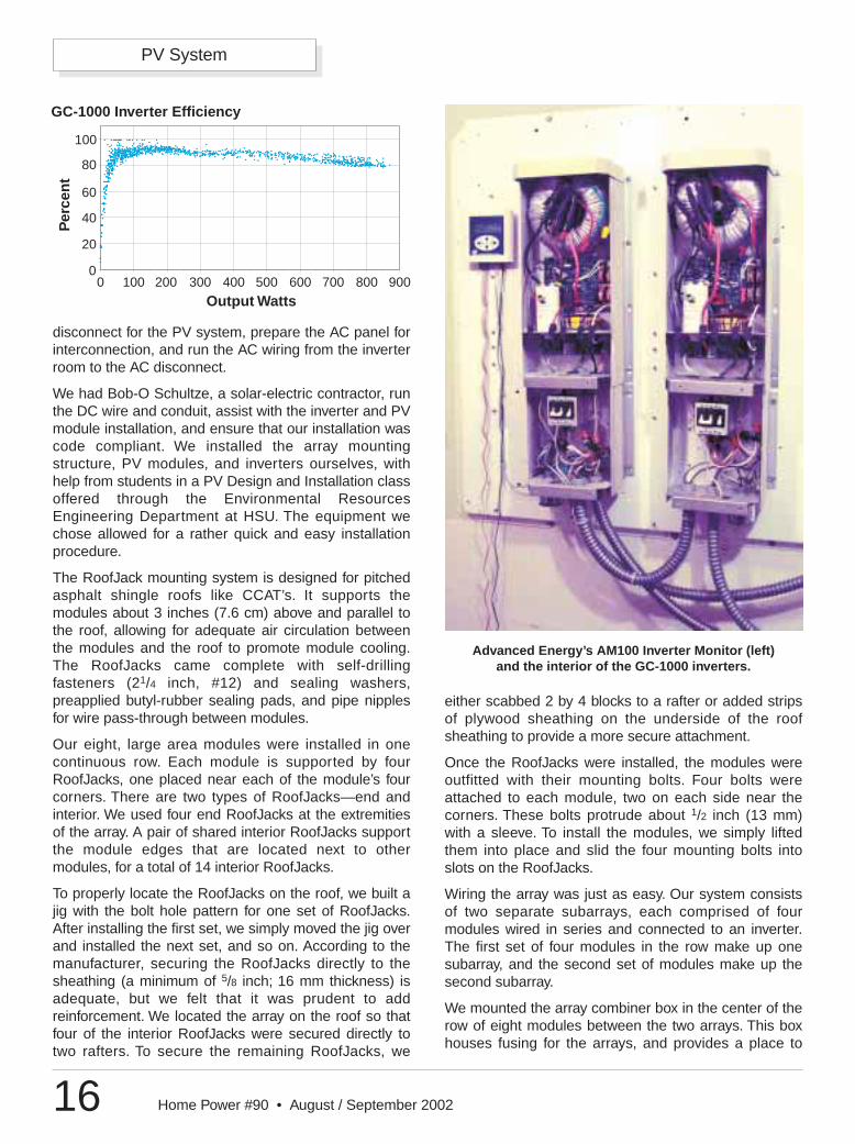
GC-1000 Inverter Efficiency
0
20
40
60
80
100
0 100 200 300 400 500 600 700 800 900
Advanced Energy’s AM100 Inverter Monitor (left) and the interior of the GC-1000 inverters.
PV System
17Home Power #90 • August / September 2002
terminate our array wiring beforerunning wire to the inverters.
The wiring between modules wasprovided by the modulemanufacturer, and came equippedwith weatherproof connectorsdesigned for series wiring ofmodules. Once the modules were inplace, we simply snapped theseconnectors together, added our solidcopper grounding wire betweenmodules, and terminated these wiresin the combiner box.
We wall mounted the AdvancedEnergy GC-1000 inverters in a roomin the basement that has historicallybeen used to house PV systemequipment. The inverters came withPV string combiner boards. Thesewere sized to handle up to sixindividual strings rated at 10 ampseach. However, we had a singlemodule string with a short circuitcurrent rating of 19.1 A, so weremoved this board. It was a littletricky to figure out how to wire theinverters without it and still use theGFI protection and AC and DCcircuit breakers that were providedwith the units.
After examining the units and speaking with themanufacturer, we found that we could wire the DC inputdirectly to the DC breaker, bypassing the combinerboard while still using the other features. AC surgearrestors were supplied with the units. Since we are notin a lightning prone area, the inverter manufacturersuggested that DC surge protection was unnecessary.
In addition to donating the inverters, Advanced Energyincluded their AM100 Inverter Monitor. This unit monitorsup to six inverters, and features an LCD display and afour-button keypad as a user interface. It logs DCcurrent, DC voltage, AC current, AC voltage, AC poweroutput, inverter efficiency, and cumulative AC energyoutput. When it collects data at 15 minute intervals, theAM100 is able to store about 30 days worth of data.
The data is downloadable via a serial communicationport. To access the data, Advanced Energy providestheir PVMON software that runs on any DOS orWindows-based personal computer. Data files arestored in Excel compatible (.CSV), comma delimitedformat. A single data file is recorded for each day. Thedata is easy to download and access.
System PerformanceThe new grid-connected PV system first startedgenerating on October 17, 2001. Of the 901 KWH totalsolar-electric energy generated as of April 23, 2002,358 KWH were used on-site, and the other 543 KWHwere fed back into the PG&E grid. During this period,we averaged 1.9 KWH per day of electrical energy use,while the PV system generated an average of 4.8 KWHper day.
Data for about a one-month period in mid-February tomid-March of 2002 was examined to evaluate theperformance of the system. During this period, the PVsystem generated an average of 4.9 KWH per day. Themaximum AC power output was 1,745 W, with acorresponding maximum DC input power of 2,155 W(81 percent average inverter efficiency). The inverters,with a rated peak efficiency of 93 percent, averaged 83percent and 85 percent, respectively. About 99 percentof the time, the input voltage to the inverters was withintheir maximum power point tracking range of 55 to 70VDC. Inverter efficiency varies as a function of ACpower output. (See the inverter efficiency plot.)
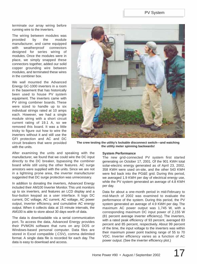
The crew testing the utility’s lockable disconnect switch—and watching the utility meter spinning backwards!
PV System
18 Home Power #90 • August / September 2002
In addition, we would like to thank theSchatz Energy Research Center for theirhelp in designing and installing thesystem, Bob-O Schultze of ElectronConnection and Peter Brant of BrantElectric for their help in installing thesystem, and the CCAT codirectors andvolunteers who helped with this project.
AccessJim Zoellick, Schatz Energy ResearchCenter, Humboldt State University,Arcata, CA 95521 • [email protected]/~serc
Andrew Posner, Campus Center for AppropriateTechnology, Humboldt State University, Arcata, CA95521 • 707-826-3551 • [email protected]/~ccat
Bob-O Schultze, Electron Connection, PO Box 203,Hornbrook, CA 96044 • 800-945-7587 or 530-475-3402 Fax: 530-475-3401 • [email protected]
Peter Brant, Brant Electric, PO Box 66, Arcata, CA95518 • 707-822-3256 • Fax: [email protected]
ASE Americas, Inc., 4 Suburban Park Dr., Billerica, MA01821 • 800-977-0777 or 978-667-5900Fax: 978-663-2868 • [email protected] • PV modules
Advanced Energy, Inc., Riverview Mill, PO Box 262,Wilton, NH 03086 • 603-654-9322 • Fax: [email protected] • Inverter
Schott Applied Power Corp., PO Box 339, Redway, CA95560 • 888-840-7191 or 707-923-2277Fax: 800-777-6648 or [email protected] • www.solarelectric.comPV mounting system
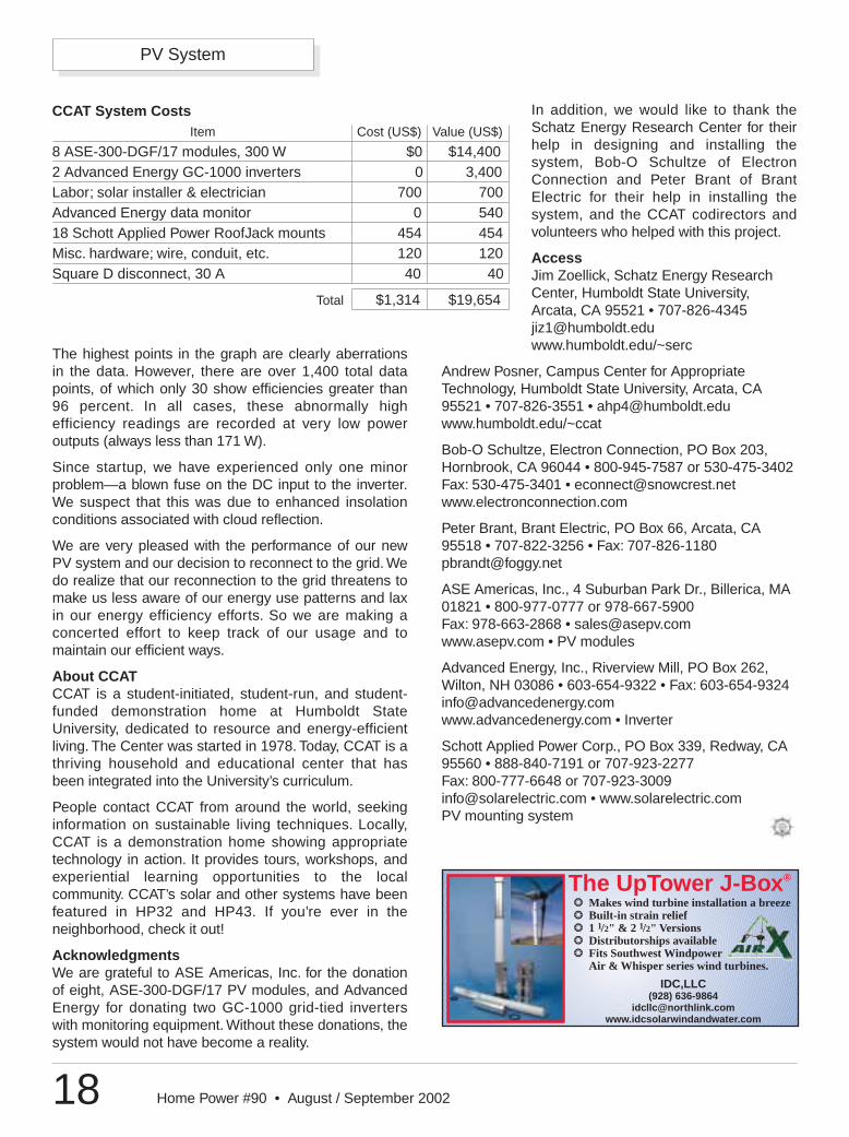
CCAT System CostsItem Cost (US$) Value (US$)
8 ASE-300-DGF/17 modules, 300 W $0 $14,4002 Advanced Energy GC-1000 inverters 0 3,400Labor; solar installer & electrician 700 700Advanced Energy data monitor 0 54018 Schott Applied Power RoofJack mounts 454 454Misc. hardware; wire, conduit, etc. 120 120Square D disconnect, 30 A 40 40
Total $1,314 $19,654
The highest points in the graph are clearly aberrationsin the data. However, there are over 1,400 total datapoints, of which only 30 show efficiencies greater than96 percent. In all cases, these abnormally highefficiency readings are recorded at very low poweroutputs (always less than 171 W).
Since startup, we have experienced only one minorproblem—a blown fuse on the DC input to the inverter.We suspect that this was due to enhanced insolationconditions associated with cloud reflection.
We are very pleased with the performance of our newPV system and our decision to reconnect to the grid. Wedo realize that our reconnection to the grid threatens tomake us less aware of our energy use patterns and laxin our energy efficiency efforts. So we are making aconcerted effort to keep track of our usage and tomaintain our efficient ways.
About CCATCCAT is a student-initiated, student-run, and student-funded demonstration home at Humboldt StateUniversity, dedicated to resource and energy-efficientliving. The Center was started in 1978. Today, CCAT is athriving household and educational center that hasbeen integrated into the University’s curriculum.
People contact CCAT from around the world, seekinginformation on sustainable living techniques. Locally,CCAT is a demonstration home showing appropriatetechnology in action. It provides tours, workshops, andexperiential learning opportunities to the localcommunity. CCAT’s solar and other systems have beenfeatured in HP32 and HP43. If you’re ever in theneighborhood, check it out!
AcknowledgmentsWe are grateful to ASE Americas, Inc. for the donationof eight, ASE-300-DGF/17 PV modules, and AdvancedEnergy for donating two GC-1000 grid-tied inverterswith monitoring equipment. Without these donations, thesystem would not have become a reality.
The UpTower J-Box®
❂ Makes wind turbine installation a breeze❂ Built-in strain relief❂ 1 1/2" & 2 1/2" Versions❂ Distributorships available❂ Fits Southwest Windpower
Air & Whisper series wind turbines.
IDC,LLC(928) 636-9864