home automation using dtmf
TRANSCRIPT

HOME AUTOMATION USING DTMF
In this competitive world human cannot spare his time to perform his daily activities
manually without any fail. The most important thing he forgets is to switch off the room
lights wherever not required. With this, even the power will be wasted up to some extent.
This can be seen more effectively in the case of lights, fans. This project gives the best
solution for electrical power wastage. Also the manual operation is completely
eliminated.
The project HOME AUTOMATION USING MOBILE is an exclusive project which
allows the user to control the electrical loads in homes by sending predefined messages to
the controlling system.
The modem provides the communication interface. It transports device protocols
transparently over the network through a serial interface. The GSM modem is a wireless
modem that works with a GSM wireless network. A wireless modem behaves like a dial-
up modem. The main difference between them is that a dial-up modem sends and
receives data through a fixed telephone line while a wireless modem sends and receives
data through radio waves.
The GSM modem will be interfaced to the microcontroller section through serial port
interface. If the user wants to switch on/off the electrical appliances, he can just send a
predefined message to the GSM modem that is interfaced to the controller section. The
controller section will have the switch controls of the devices. All the devices which are
to be controlled will be connected to the controlling device i.e., to the microcontroller
section. The microcontroller in return, sends a message to the mobile number about the
status of all the loads.
The user has to send a predefined SMS to the modem and the modem will intimate the
controller about the received message and the controller will act in accordance with the
received message such as switching on/off an industrial electrical load.
SOFTWARE AND HARDWARE TOOLS:
Software Tools:
1. Keil compiler
2. Orcad.
Hardware Tools:
1. Microcontroller AT89S52.
2. GSM modem.
3. TRIAC and TRAIC driver (MOC 3021).

Block diagram
INTRODUCTION TO EMBEDDED SYSTEMS
An embedded system is a special-purpose system in which the computer
is completely encapsulated by or dedicated to the device or system it controls. Unlike a
general-purpose computer, such as a personal computer, an embedded system performs
one or a few pre-defined tasks, usually with very specific requirements. Since the system
is dedicated to specific tasks, design engineers can optimize it, reducing the size and cost
of the product. Embedded systems are often mass-produced, benefiting from economies
of scale.
Personal digital assistants (PDAs) or handheld computers are generally considered
embedded devices because of the nature of their hardware design, even though they are
more expandable in software terms. This line of definition continues to blur as devices
expand.

Physically, embedded systems range from portable devices such as digital watches and
MP3 players, to large stationary installations like traffic lights, factory controllers, or the
systems controlling nuclear power plants.
In terms of complexity embedded systems can range from very simple with a single
microcontroller chip, to very complex with multiple units, peripherals and networks
mounted inside a large chassis or enclosure.
Examples of embedded systems
• Automatic teller machines (ATMs)
• Avionics, such as inertial guidance systems, flight control hardware/software and
other integrated systems in aircraft and missiles
• Cellular telephones and telephone switches
• engine controllers and antilock brake controllers for automobiles
• Home automation products, such as thermostats, air conditioners, sprinklers, and
security monitoring systems
• Handheld calculators
• Handheld computers
• Household appliances, including microwave ovens, washing machines, television
sets, DVD players and recorders
• Medical equipment
• Personal digital assistant
• Videogame consoles
• Computer peripherals such as routers and printers
• Industrial controllers for remote machine operation.
History
In the earliest years of computers in the 1940s, computers were sometimes dedicated to a
single task, but were too large to be considered "embedded". Over time however, the
concept of programmable controllers developed from a mix of computer technology,
solid state devices, and traditional electromechanical sequences.
The first recognizably modern embedded system was the Apollo Guidance Computer,
developed by Charles Stark Draper at the MIT Instrumentation Laboratory. At the
project's inception, the Apollo guidance computer was considered the riskiest item in the
Apollo project. The use of the then new monolithic integrated circuits, to reduce the size
and weight, increased this risk.
The first mass-produced embedded system was the Autonetics D-17 guidance computer
for the Minuteman (missile), released in 1961. It was built from transistor logic and had a
hard disk for main memory. When the Minuteman II went into production in 1966, the D-
17 was replaced with a new computer that was the first high-volume use of integrated
circuits. This program alone reduced prices on quad nand gate ICs from $1000/each to
$3/each, permitting their use in commercial products.
Since these early applications in the 1960s, embedded systems have come down in price.
There has also been an enormous rise in processing power and functionality. For example
the first microprocessor was the Intel 4004, which found its way into calculators and
other small systems, but required external memory and support chips.
In 1978 National Engineering Manufacturers Association released the standard for a
programmable microcontroller. The definition was an almost any computer-based
controller. They included single board computers, numerical controllers, and sequential
controllers in order to perfom event-based instructions.
By the mid-1980s, many of the previously external system components had been
integrated into the same chip as the processor, resulting in integrated circuits called
microcontrollers, and widespread use of embedded systems became feasible.
As the cost of a microcontroller fell below $1, it became feasible to replace expensive
knob-based analog components such as potentiometers and variable capacitors with
digital electronics controlled by a small microcontroller with up/down buttons or knobs.
By the end of the 80s, embedded systems were the norm rather than the exception for
almost all electronics devices, a trend which has continued since.
Characteristics
Embedded systems are designed to do some specific task, rather than be a general-
purpose computer for multiple tasks. Some also have real-time performance constraints
that must be met, for reason such as safety and usability; others may have low or no
performance requirements, allowing the system hardware to be simplified to reduce costs.
An embedded system is not always a separate block - very often it is physically built-in to
the device it is controlling
The software written for embedded systems is often called firmware, and is stored in
read-only memory or Flash memory chips rather than a disk drive. It often runs with
limited computer hardware resources: small or no keyboard, screen, and little memory.
User interfaces
Embedded systems range from no user interface at all - dedicated only to one task - to
full user interfaces similar to desktop operating systems in devices such as PDAs.
Simple systems
Simple embedded devices use buttons, LEDs, and small character- or digit-only displays,
often with a simple menu system.
In more complex systems

A full graphical screen, with touch sensing or screen-edge buttons provides flexibility
while minimizing space used: the meaning of the buttons can change with the screen, and
selection involves the natural behavior of pointing at what's desired.
Handheld systems often have a screen with a "joystick button" for a pointing device.
The rise of the World Wide Web has given embedded designers another quite different
option: providing a web page interface over a network connection. This avoids the cost of
a sophisticated display, yet provides complex input and display capabilities when needed,
on another computer. This is successful for remote, permanently installed equipment. In
particular, routers take advantage of this ability.
CPU platform
Embedded processors can be broken into two distinct categories: microprocessors (μP)
and micro controllers (μC). Micro controllers have built-in peripherals on the chip,
reducing size of the system.
There are many different CPU architectures used in embedded designs such as ARM,
MIPS, Coldfire/68k, PowerPC, x86, PIC, 8051, Atmel AVR, Renesas H8, SH, V850, FR-
V, M32R, Z80, Z8, etc. This in contrast to the desktop computer market, which is
currently limited to just a few competing architectures.
PC/104 and PC/104+ are a typical base for small, low-volume embedded and rugged
system design. These often use DOS, Linux, NetBSD, or an embedded real-time
operating system such as QNX or VxWorks.
A common configuration for very-high-volume embedded systems is the system on a
chip (SoC), an application-specific integrated circuit (ASIC), for which the CPU core was
purchased and added as part of the chip design. A related scheme is to use a field-
programmable gate array (FPGA), and program it with all the logic, including the CPU.
Peripherals

Embedded Systems talk with the outside world via peripherals, such as:
• Serial Communication Interfaces (SCI): RS-232, RS-422, RS-485 etc
• Synchronous Serial Communication Interface: I2C, JTAG, SPI, SSC and ESSI
• Universal Serial Bus (USB)
• Networks: Controller Area Network, LonWorks, etc
• Timers: PLL(s), Capture/Compare and Time Processing Units
• Discrete IO: aka General Purpose Input Output (GPIO)
Tools
As for other software, embedded system designers use compilers, assemblers, and
debuggers to develop embedded system software. However, they may also use some
more specific tools:
• An in-circuit emulator (ICE) is a hardware device that replaces or plugs into the
microprocessor, and provides facilities to quickly load and debug experimental
code in the system.
• Utilities to add a checksum or CRC to a program, so the embedded system can
check if the program is valid.
• For systems using digital signal processing, developers may use a math
workbench such as MathCad or Mathematica to simulate the mathematics.
• Custom compilers and linkers may be used to improve optimization for the
particular hardware.
• An embedded system may have its own special language or design tool, or add
enhancements to an existing language.
Software tools can come from several sources:
• Software companies that specialize in the embedded market
• Ported from the GNU software development tools
• Sometimes, development tools for a personal computer can be used if the
embedded processor is a close relative to a common PC processor

Debugging
Embedded Debugging may be performed at different levels, depending on the facilities
available, ranging from assembly- or source-level debugging with an in-circuit emulator
or in-circuit debugger, to output from serial debug ports or JTAG/Nexus interfaces, to an
emulated environment running on a personal computer.
As the complexity of embedded systems grows, higher level tools and operating systems
are migrating into machinery where it makes sense. For example, cell phones, personal
digital assistants and other consumer computers often need significant software that is
purchased or provided by a person other than the manufacturer of the electronics. In these
systems, an open programming environment such as Linux, NetBSD, OSGi or Embedded
Java is required so that the third-party software provider can sell to a large market.
Reliability
Embedded systems often reside in machines that are expected to run continuously for
years without errors, and in some cases recover by themselves if an error occurs.
Therefore the software is usually developed and tested more carefully than that for
personal computers, and unreliable mechanical moving parts such as disk drives,
switches or buttons are avoided.
Recovery from errors may be achieved with techniques such as a watchdog timer that
resets the computer unless the software periodically notifies the watchdog.
Specific reliability issues may include:
1. The system cannot safely be shut down for repair, or it is too inaccessible to
repair. Solutions may involve subsystems with redundant spares that can be
switched over to, or software "limp modes" that provide partial function.

Examples include space systems, undersea cables, navigational beacons, bore-
hole systems, and automobiles.
2. The system must be kept running for safety reasons. "Limp modes" are less
tolerable. Often backups are selected by an operator. Examples include aircraft
navigation, reactor control systems, safety-critical chemical factory controls, train
signals, engines on single-engine aircraft.
3. The system will lose large amounts of money when shut down: Telephone
switches, factory controls, bridge and elevator controls, funds transfer and market
making, automated sales and service.
High vs Low Volume
For high volume systems such as portable music players or mobile phones, minimizing
cost is usually the primary design consideration. Engineers typically select hardware that
is just “good enough” to implement the necessary functions.
For low-volume or prototype embedded systems, general purpose computers may be
adapted by limiting the programs or by replacing the operating system with a real-time
operating system.
Embedded software architectures
There are several different types of software architecture in common use.
Simple control loop
In this design, the software simply has a loop. The loop calls subroutines, each of which
manages a part of the hardware or software.
Interrupt controlled system
Some embedded systems are predominantly interrupt controlled. This means that tasks
performed by the system are triggered by different kinds of events. An interrupt could be

generated for example by a timer in a predefined frequency, or by a serial port controller
receiving a byte.
These kinds of systems are used if event handlers need low latency and the event
handlers are short and simple.
Usually these kinds of systems run a simple task in a main loop also, but this task is not
very sensitive to unexpected delays. The tasks performed in the interrupt handlers should
be kept short to keep the interrupt latency to a minimum.
Some times longer tasks are added to a queue structure in the interrupt handler to be
processed in the main loop later. This method brings the system close to a multitasking
kernel with discrete processes.
Cooperative multitasking
A no preemptive multitasking system is very similar to the simple control loop scheme,
except that the loop is hidden in an API. The programmer defines a series of tasks, and
each task gets its own environment to "run" in. Then, when a task is idle, it calls an idle
routine (usually called "pause", "wait", "yield", etc.).
The advantages and disadvantages are very similar to the control loop, except that adding
new software is easier, by simply writing a new task, or adding to the queue-interpreter.
Preemptive multitasking
In this type of system, a low-level piece of code switches between tasks based on a timer.
This is the level at which the system is generally considered to have an "operating
system", and introduces all the complexities of managing multiple tasks running
seemingly at the same time.
Any piece of task code can damage the data of another task; they must be precisely
separated. Access to shared data must be controlled by some synchronization strategy,
such as message queues, semaphores or a non-blocking synchronization scheme.

Because of these complexities, it is common for organizations to buy a real-time
operating system, allowing the application programmers to concentrate on device
functionality rather than operating system services.
Power Supply
Power supply is a reference to a source of electrical power. A device or system that supplies electrical or other types of energy to an output load or group of loads is called a power supply unit or PSU. The term is most commonly applied to electrical energy supplies, less often to mechanical ones, and rarely to others
This power supply section is required to convert AC signal to DC signal and also to reduce the amplitude of the signal. The available voltage signal from the mains is 230V/50Hz which is an AC voltage, but the required is DC voltage(no frequency) with the amplitude of +5V and +12V for various applications.
In this section we have Transformer, Bridge rectifier, are connected serially and voltage regulators for +5V and +12V (7805 and 7812) via a capacitor (1000µF) in parallel are connected parallel as shown in the circuit diagram below. Each voltage regulator output is again is connected to the capacitors of values (100µF, 10µF, 1 µF, 0.1 µF) are connected parallel through which the corresponding output(+5V or +12V) are taken into consideration.
Circuit Explanation

1) Transformer
A transformer is a device that transfers electrical energy from one circuit to another through inductively coupled electrical conductors. A changing current in the first circuit (the primary) creates a changing magnetic field; in turn, this magnetic field induces a changing voltage in the second circuit (the secondary). By adding a load to the secondary circuit, one can make current flow in the transformer, thus transferring energy from one circuit to the other.
The secondary induced voltage VS, of an ideal transformer, is scaled from the primary VP by a factor equal to the ratio of the number of turns of wire in their respective windings:
Basic principle
The transformer is based on two principles: firstly, that an electric current can produce a magnetic field (electromagnetism) and secondly that a changing magnetic field within a coil of wire induces a voltage across the ends of the coil (electromagnetic induction). By changing the current in the primary coil, it changes the strength of its magnetic field; since the changing magnetic field extends into the secondary coil, a voltage is induced across the secondary.
A simplified transformer design is shown below. A current passing through the primary coil creates a magnetic field. The primary and secondary coils are wrapped around a core of very high magnetic permeability, such as iron; this ensures that most of the magnetic field lines produced by the primary current are within the iron and pass through the secondary coil as well as the primary coil.
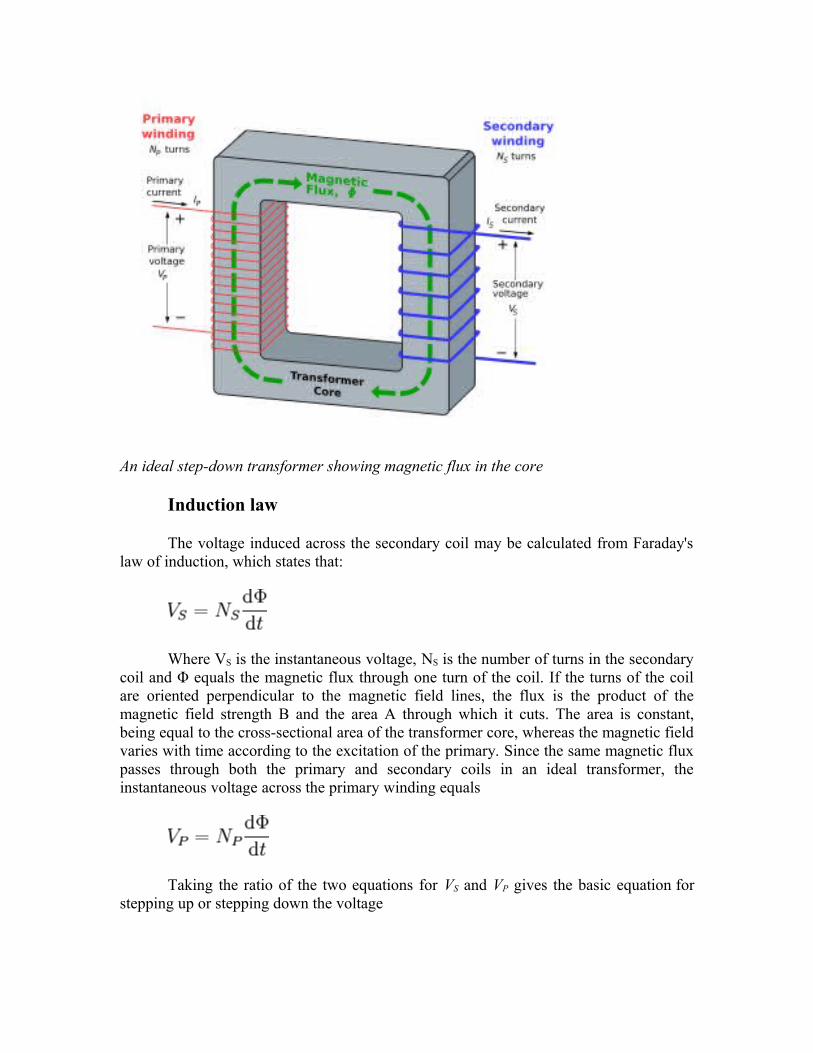
An ideal step-down transformer showing magnetic flux in the core
Induction law
The voltage induced across the secondary coil may be calculated from Faraday's law of induction, which states that:
Where VS is the instantaneous voltage, NS is the number of turns in the secondary coil and Φ equals the magnetic flux through one turn of the coil. If the turns of the coil are oriented perpendicular to the magnetic field lines, the flux is the product of the magnetic field strength B and the area A through which it cuts. The area is constant, being equal to the cross-sectional area of the transformer core, whereas the magnetic field varies with time according to the excitation of the primary. Since the same magnetic flux passes through both the primary and secondary coils in an ideal transformer, the instantaneous voltage across the primary winding equals
Taking the ratio of the two equations for VS and VP gives the basic equation for stepping up or stepping down the voltage

Ideal power equation
If the secondary coil is attached to a load that allows current to flow, electrical power is transmitted from the primary circuit to the secondary circuit. Ideally, the transformer is perfectly efficient; all the incoming energy is transformed from the primary circuit to the magnetic field and into the secondary circuit. If this condition is met, the incoming electric power must equal the outgoing power.
Pincoming = IPVP = Poutgoing = ISVS
giving the ideal transformer equation
Pin-coming = IPVP = Pout-going = ISVS
giving the ideal transformer equation
If the voltage is increased (stepped up) (VS > VP), then the current is decreased (stepped down) (IS < IP) by the same factor. Transformers are efficient so this formula is a reasonable approximation.

If the voltage is increased (stepped up) (VS > VP), then the current is decreased (stepped down) (IS < IP) by the same factor. Transformers are efficient so this formula is a reasonable approximation.
The impedance in one circuit is transformed by the square of the turns ratio. For example, if an impedance ZS is attached across the terminals of the secondary coil, it appears to the primary circuit to have an impedance of
This relationship is reciprocal, so that the impedance ZP of the primary circuit appears to the secondary to be
Detailed operation
The simplified description above neglects several practical factors, in particular the primary current required to establish a magnetic field in the core, and the contribution to the field due to current in the secondary circuit.
Models of an ideal transformer typically assume a core of negligible reluctance with two windings of zero resistance. When a voltage is applied to the primary winding, a small current flows, driving flux around the magnetic circuit of the core. The current required to create the flux is termed the magnetizing current; since the ideal core has been assumed to have near-zero reluctance, the magnetizing current is negligible, although still required to create the magnetic field.
The changing magnetic field induces an electromotive force (EMF) across each winding. Since the ideal windings have no impedance, they have no associated voltage drop, and so the voltages VP and VS measured at the terminals of the transformer, are equal to the corresponding EMFs. The primary EMF, acting as it does in opposition to the primary voltage, is sometimes termed the "back EMF". This is due to Lenz's law which states that the induction of EMF would always be such that it will oppose development of any such change in magnetic field.
2) Bridge Rectifier
A diode bridge or bridge rectifier is an arrangement of four diodes in a bridge configuration that provides the same polarity of output voltage for any polarity of input voltage. When used in its most common application, for conversion of alternating current (AC) input into direct current (DC) output, it is known as a bridge rectifier. A bridge rectifier provides full-wave rectification from a two-wire AC input, resulting in lower cost and weight as compared to a center-tapped transformer design, but has two diode
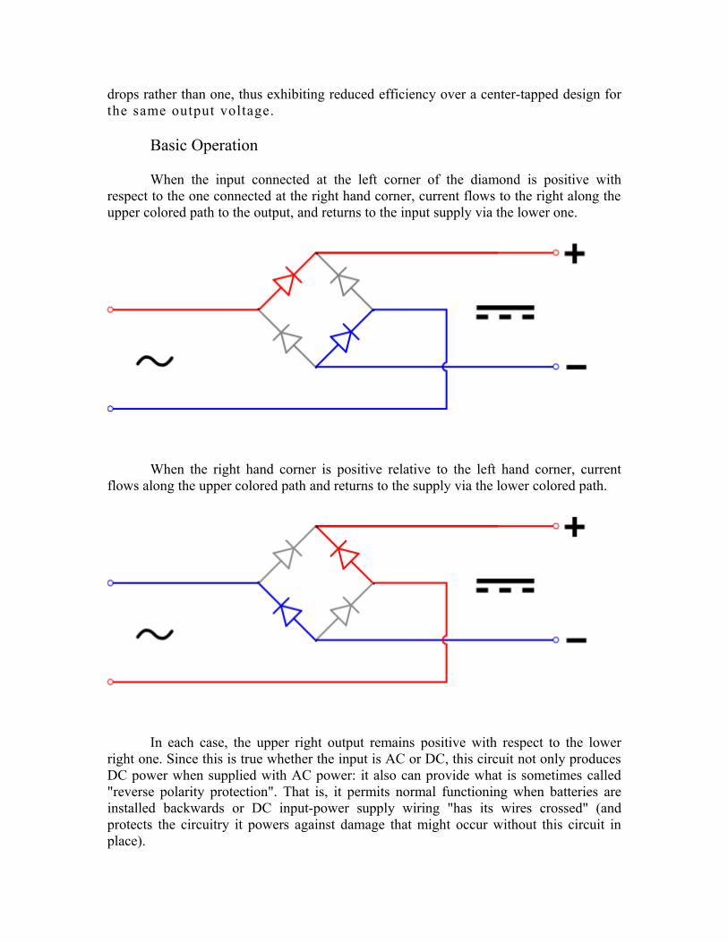
drops rather than one, thus exhibiting reduced efficiency over a center-tapped design for the same output voltage.
Basic Operation
When the input connected at the left corner of the diamond is positive with respect to the one connected at the right hand corner, current flows to the right along the upper colored path to the output, and returns to the input supply via the lower one.
When the right hand corner is positive relative to the left hand corner, current flows along the upper colored path and returns to the supply via the lower colored path.
In each case, the upper right output remains positive with respect to the lower right one. Since this is true whether the input is AC or DC, this circuit not only produces DC power when supplied with AC power: it also can provide what is sometimes called "reverse polarity protection". That is, it permits normal functioning when batteries are installed backwards or DC input-power supply wiring "has its wires crossed" (and protects the circuitry it powers against damage that might occur without this circuit in place).

Prior to availability of integrated electronics, such a bridge rectifier was always constructed from discrete components. Since about 1950, a single four-terminal component containing the four diodes connected in the bridge configuration became a standard commercial component and is now available with various voltage and current ratings.
Output smoothing (Using Capacitor)
For many applications, especially with single phase AC where the full-wave bridge serves to convert an AC input into a DC output, the addition of a capacitor may be important because the bridge alone supplies an output voltage of fixed polarity but pulsating magnitude (see diagram above).

The function of this capacitor, known as a reservoir capacitor (aka smoothing capacitor) is to lessen the variation in (or 'smooth') the rectified AC output voltage waveform from the bridge. One explanation of 'smoothing' is that the capacitor provides a low impedance path to the AC component of the output, reducing the AC voltage across, and AC current through, the resistive load. In less technical terms, any drop in the output voltage and current of the bridge tends to be cancelled by loss of charge in the capacitor.
This charge flows out as additional current through the load. Thus the change of load current and voltage is reduced relative to what would occur without the capacitor. Increases of voltage correspondingly store excess charge in the capacitor, thus moderating the change in output voltage / current. Also see rectifier output smoothing.
The simplified circuit shown has a well deserved reputation for being dangerous, because, in some applications, the capacitor can retain a lethal charge after the AC power source is removed. If supplying a dangerous voltage, a practical circuit should include a reliable way to safely discharge the capacitor. If the normal load can not be guaranteed to perform this function, perhaps because it can be disconnected, the circuit should include a bleeder resistor connected as close as practical across the capacitor. This resistor should consume a current large enough to discharge the capacitor in a reasonable time, but small enough to avoid unnecessary power waste.
Because a bleeder sets a minimum current drain, the regulation of the circuit, defined as percentage voltage change from minimum to maximum load, is improved. However in many cases the improvement is of insignificant magnitude.
The capacitor and the load resistance have a typical time constant τ = RC where C and R are the capacitance and load resistance respectively. As long as the load resistor is large enough so that this time constant is much longer than the time of one ripple cycle, the above configuration will produce a smoothed DC voltage across the load.
In some designs, a series resistor at the load side of the capacitor is added. The smoothing can then be improved by adding additional stages of capacitor–resistor pairs, often done only for sub-supplies to critical high-gain circuits that tend to be sensitive to supply voltage noise.
The idealized waveforms shown above are seen for both voltage and current when the load on the bridge is resistive. When the load includes a smoothing capacitor, both the voltage and the current waveforms will be greatly changed. While the voltage is smoothed, as described above, current will flow through the bridge only during the time when the input voltage is greater than the capacitor voltage. For example, if the load draws an average current of n Amps, and the diodes conduct for 10% of the time, the average diode current during conduction must be 10n Amps. This non-sinusoidal current leads to harmonic distortion and a poor power factor in the AC supply.

In a practical circuit, when a capacitor is directly connected to the output of a bridge, the bridge diodes must be sized to withstand the current surge that occurs when the power is turned on at the peak of the AC voltage and the capacitor is fully discharged. Sometimes a small series resistor is included before the capacitor to limit this current, though in most applications the power supply transformer's resistance is already sufficient.
Output can also be smoothed using a choke and second capacitor. The choke tends to keep the current (rather than the voltage) more constant. Due to the relatively high cost of an effective choke compared to a resistor and capacitor this is not employed in modern equipment.
Some early console radios created the speaker's constant field with the current from the high voltage ("B +") power supply, which was then routed to the consuming circuits, (permanent magnets were considered too weak for good performance) to create the speaker's constant magnetic field. The speaker field coil thus performed 2 jobs in one: it acted as a choke, filtering the power supply, and it produced the magnetic field to operate the speaker.
3) Voltage Regulator
A voltage regulator is an electrical regulator designed to automatically maintain a constant voltage level.
The 78xx (also sometimes known as LM78xx) series of devices is a family of self-contained fixed linear voltage regulator integrated circuits. The 78xx family is a very popular choice for many electronic circuits which require a regulated power supply, due to their ease of use and relative cheapness. When specifying individual ICs within this family, the xx is replaced with a two-digit number, which indicates the output voltage the particular device is designed to provide (for example, the 7805 has a 5 volt output, while the 7812 produces 12 volts). The 78xx line is positive voltage regulators, meaning that they are designed to produce a voltage that is positive relative to a common ground. There is a related line of 79xx devices which are complementary negative voltage regulators. 78xx and 79xx ICs can be used in combination to provide both positive and negative supply voltages in the same circuit, if necessary.
78xx ICs have three terminals and are most commonly found in the TO220 form factor, although smaller surface-mount and larger TrO3 packages are also available from some manufacturers. These devices typically support an input voltage which can be anywhere from a couple of volts over the intended output voltage, up to a maximum of 35 or 40 volts, and can typically provide up to around 1 or 1.5 amps of current (though smaller or larger packages may have a lower or higher current rating).
MICRO CONTROLLERS
Microprocessors vs. Microcontrollers:
• Microprocessors are single-chip CPUs used in microcomputers.
• Microcontrollers and microprocessors are different in three main aspects: hardware
architecture, applications, and instruction set features.
• Hardware architecture: A microprocessor is a single chip CPU while a microcontroller
is a single IC contains a CPU and much of remaining circuitry of a complete computer
(e.g., RAM, ROM, serial interface, parallel interface, timer, interrupt handling circuit).
• Applications: Microprocessors are commonly used as a CPU in computers while
microcontrollers are found in small, minimum component designs performing control
oriented activities.
• Microprocessor instruction sets are processing Intensive.
• Their instructions operate on nibbles, bytes, words, or even double words.
• Addressing modes provide access to large arrays of data using pointers and offsets.
• They have instructions to set and clear individual bits and perform bit operations.
• They have instructions for input/output operations, event timing, enabling and setting
priority levels for interrupts caused by external stimuli.
• Processing power of a microcontroller is much less than a microprocessor.
Difference between 8051 and 8052:
The 8052 microcontroller is the 8051's "big brother." It is a slightly more powerful
microcontroller, sporting a number of additional features which the developer may make
use of:
• 256 bytes of Internal RAM (compared to 128 in the standard 8051).
• A third 16-bit timer, capable of a number of new operation modes and 16-bit
reloads.
• Additional SFRs to support the functionality offered by the third timer.
AT89S52:
Features:
• Compatible with MCS-51 Products
• 8K Bytes of In-System Programmable (ISP) Flash Memory
– Endurance: 1000 Write/Erase Cycles
• 4.0V to 5.5V Operating Range
• Fully Static Operation: 0 Hz to 33 MHz
• Three-level Program Memory Lock
• 256K Internal RAM
• 32 Programmable I/O Lines
• 3 16-bit Timer/Counters
• Eight Interrupt Sources
• Full Duplex UART Serial Channel
• Low-power Idle and Power-down Modes
• Interrupt Recovery from Power-down Mode
• Watchdog Timer
• Dual Data Pointer

• Power-off Flag
DESCRIPTION OF MICROCONTROLLER 89S52:
The AT89S52 is a low-power, high-performance CMOS 8-bit micro
controller with 8Kbytes of in-system programmable Flash memory. The
device is manufactured
Using Atmel’s high-density nonvolatile memory technology and is
compatible with the industry-standard 80C51 micro controller. The on-chip
Flash allows the program memory to be reprogrammed in-system or by a
conventional nonvolatile memory programmer. By combining a versatile 8-
bit CPU with in-system programmable flash one monolithic chip; the Atmel
AT89S52 is a powerful micro controller, which provides a highly flexible
and cost-effective solution to many embedded control applications.

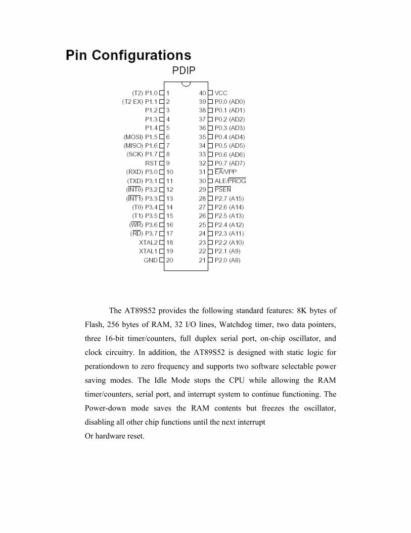
The AT89S52 provides the following standard features: 8K bytes of
Flash, 256 bytes of RAM, 32 I/O lines, Watchdog timer, two data pointers,
three 16-bit timer/counters, full duplex serial port, on-chip oscillator, and
clock circuitry. In addition, the AT89S52 is designed with static logic for
perationdown to zero frequency and supports two software selectable power
saving modes. The Idle Mode stops the CPU while allowing the RAM
timer/counters, serial port, and interrupt system to continue functioning. The
Power-down mode saves the RAM contents but freezes the oscillator,
disabling all other chip functions until the next interrupt
Or hardware reset.

PIN DESCRIPTION OF MICROCONTROLLER 89S52
VCC
Supply voltage.
GND
Ground.
Port 0
Port 0 is an 8-bit open drain bi-directional I/O port. As an output port,
each pin can sink eight TTL inputs. When 1sare written to port 0 pins, the
pins can be used as high impedance inputs. Port 0 can also be configured to
be the multiplexed low order address/data bus during accesses to external
program and data memory. In this mode, P0 has internal pull-ups. Port 0 also
receives the code bytes during Flash programming and outputs the code bytes
during program verification. External pull-ups are required during program
verification
Port 1
Port 1 is an 8-bit bi-directional I/O port with internal pull-ups. The Port 1 Output
buffers can sink/source four TTL inputs. When 1s are written to Port 1 pins, they are
pulled high by the internal pull-ups and can be used as inputs. In addition, P1.0 and P1.1
can be configured to be the timer/counter 2 external count input
(P1.0/T2) and the timer/counter 2 trigger input P1.1/T2EX), respectively, as
shown in the following table. Port 1 also receives the low-order address bytes
during Flash programming and verification.
Port 2
Port 2 is an 8-bit bi-directional I/O port with internal pull-ups. The Port 2
output buffers can sink/source four TTL inputs. When 1s are written to Port 2
pins, they are pulled high by the internal pull-ups and can be used as inputs.
Port 2 emits the high-order address byte during fetches from external
program memory and during accesses to external data memory that use 16-bit
addresses (MOVX @DPTR). In this application, Port 2 uses strong internal
pull-ups when emitting 1s. During accesses to external data memory that use
8-bit addresses (MOVX @ RI), Port 2emits the contents of the P2 Special
Function Register. Port 2 also receives the high-order address bits and some
control signals during Flash programming and verification.
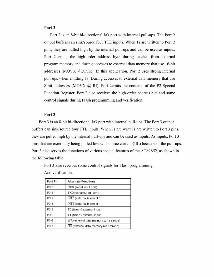
Port 3
Port 3 is an 8-bit bi-directional I/O port with internal pull-ups. The Port 3 output
buffers can sink/source four TTL inputs. When 1s are writt 1s are written to Port 3 pins,
they are pulled high by the internal pull-ups and can be used as inputs. As inputs, Port 3
pins that are externally being pulled low will source current (IIL) because of the pull-ups.
Port 3 also serves the functions of various special features of the AT89S52, as shown in
the following table.
Port 3 also receives some control signals for Flash programming
And verification.

RST
Reset input. A high on this pin for two machine cycles while the
oscillator is running resets the device.
ALE/PROG
Address Latch Enable (ALE) is an output pulse for latching the low byte of the
address during accesses to external memory. This pin is also the program pulse input
(PROG) during Flash programming. In normal operation, ALE is emitted at a constant
rate of1/6 the oscillator frequency and may be used for external timing or clocking
purposes. Note, however, that one ALE pulse is skipped during each access to external
data Memory. If desired, ALE operation can be disabled by setting bit 0 of SFR location
8EH. With the bit set, ALE is active only during a MOVX or MOVC
instruction. Otherwise, the pin is weakly pulled high. Setting the ALE-disable
bit has no effect if the micro controller is in external execution mode.
PSEN
Program Store Enable (PSEN) is the read strobe to external program
memory. When the AT89S52 is executing code from external program
memory, PSEN is activated twice each machine cycle, except that two PSEN
activations are skipped during each access to external data memory.
EA/VPP
External Access Enable. EA must be strapped to GND in order to enable
the device to fetch code from external program memory locations starting at
0000H up to FFFFH.Note, however, that if lock bit 1 is programmed, EA will
be internally latched on reset. A should be strapped to VCC for internal
program executions. This pin also receives the 12-voltProgramming enables
voltage (VPP) during Flash programming.
XTAL1
Input to the inverting oscillator amplifier and input to the internal clock
operating circuit.
XTAL2
Output from the inverting oscillator amplifier.
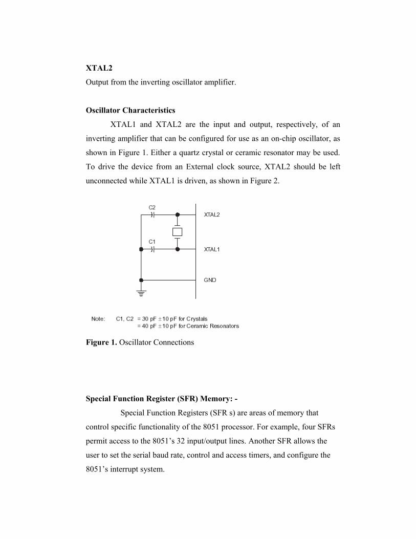
Oscillator Characteristics
XTAL1 and XTAL2 are the input and output, respectively, of an
inverting amplifier that can be configured for use as an on-chip oscillator, as
shown in Figure 1. Either a quartz crystal or ceramic resonator may be used.
To drive the device from an External clock source, XTAL2 should be left
unconnected while XTAL1 is driven, as shown in Figure 2.
Figure 1. Oscillator Connections
Special Function Register (SFR) Memory: -
Special Function Registers (SFR s) are areas of memory that
control specific functionality of the 8051 processor. For example, four SFRs
permit access to the 8051’s 32 input/output lines. Another SFR allows the
user to set the serial baud rate, control and access timers, and configure the
8051’s interrupt system.
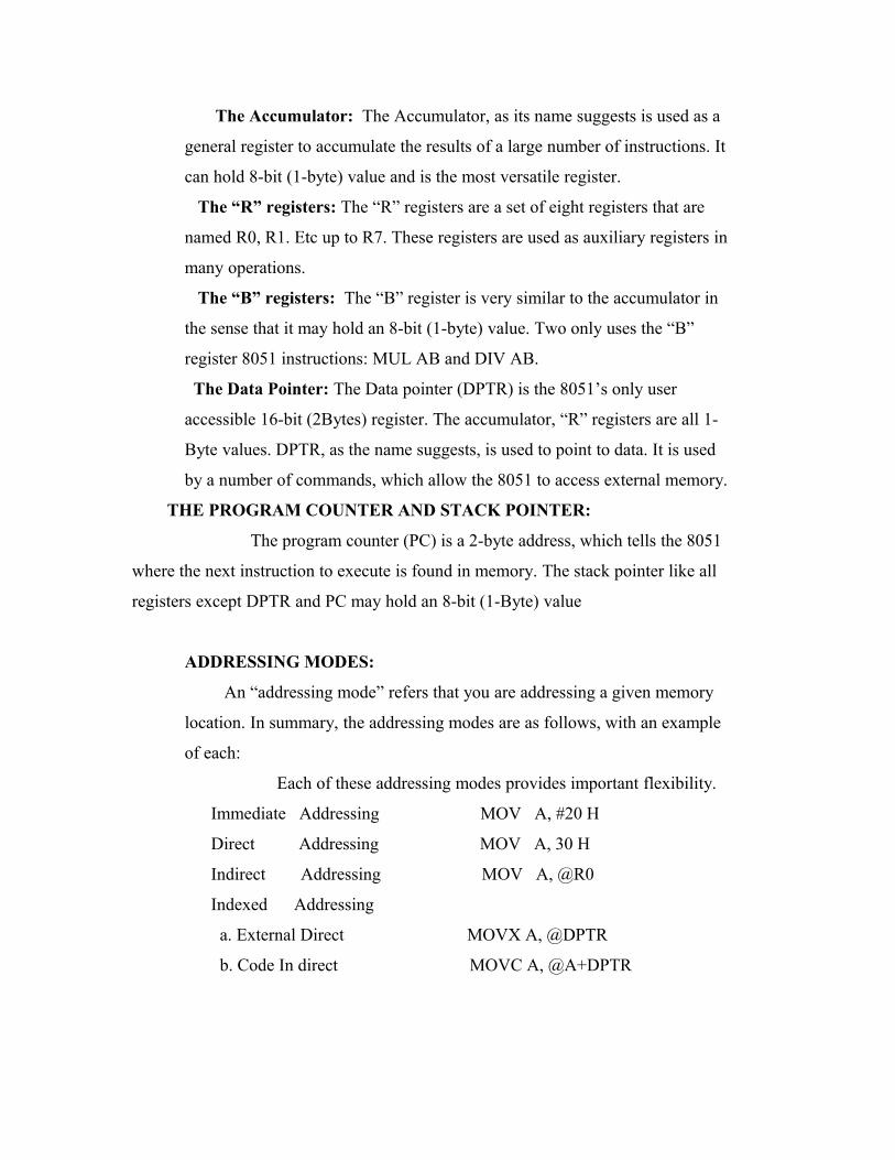
The Accumulator: The Accumulator, as its name suggests is used as a
general register to accumulate the results of a large number of instructions. It
can hold 8-bit (1-byte) value and is the most versatile register.
The “R” registers: The “R” registers are a set of eight registers that are
named R0, R1. Etc up to R7. These registers are used as auxiliary registers in
many operations.
The “B” registers: The “B” register is very similar to the accumulator in
the sense that it may hold an 8-bit (1-byte) value. Two only uses the “B”
register 8051 instructions: MUL AB and DIV AB.
The Data Pointer: The Data pointer (DPTR) is the 8051’s only user
accessible 16-bit (2Bytes) register. The accumulator, “R” registers are all 1-
Byte values. DPTR, as the name suggests, is used to point to data. It is used
by a number of commands, which allow the 8051 to access external memory.
THE PROGRAM COUNTER AND STACK POINTER:
The program counter (PC) is a 2-byte address, which tells the 8051
where the next instruction to execute is found in memory. The stack pointer like all
registers except DPTR and PC may hold an 8-bit (1-Byte) value
ADDRESSING MODES:
An “addressing mode” refers that you are addressing a given memory
location. In summary, the addressing modes are as follows, with an example
of each:
Each of these addressing modes provides important flexibility.
Immediate Addressing MOV A, #20 H
Direct Addressing MOV A, 30 H
Indirect Addressing MOV A, @R0
Indexed Addressing
a. External Direct MOVX A, @DPTR
b. Code In direct MOVC A, @A+DPTR
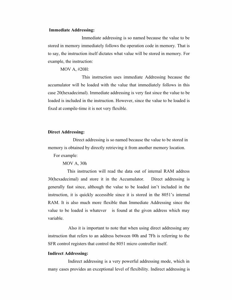
Immediate Addressing:
Immediate addressing is so named because the value to be
stored in memory immediately follows the operation code in memory. That is
to say, the instruction itself dictates what value will be stored in memory. For
example, the instruction:
MOV A, #20H:
This instruction uses immediate Addressing because the
accumulator will be loaded with the value that immediately follows in this
case 20(hexadecimal). Immediate addressing is very fast since the value to be
loaded is included in the instruction. However, since the value to be loaded is
fixed at compile-time it is not very flexible.
Direct Addressing:
Direct addressing is so named because the value to be stored in
memory is obtained by directly retrieving it from another memory location.
For example:
MOV A, 30h
This instruction will read the data out of internal RAM address
30(hexadecimal) and store it in the Accumulator. Direct addressing is
generally fast since, although the value to be loaded isn’t included in the
instruction, it is quickly accessible since it is stored in the 8051’s internal
RAM. It is also much more flexible than Immediate Addressing since the
value to be loaded is whatever is found at the given address which may
variable.
Also it is important to note that when using direct addressing any
instruction that refers to an address between 00h and 7Fh is referring to the
SFR control registers that control the 8051 micro controller itself.
Indirect Addressing:
Indirect addressing is a very powerful addressing mode, which in
many cases provides an exceptional level of flexibility. Indirect addressing is

also the only way to access the extra 128 bytes of internal RAM found on the
8052. Indirect addressing appears as follows:
MOV A, @R0:
This instruction causes the 8051 to analyze Special Function
Register (SFR) Memory:
Special Function Registers (SFRs) are areas of memory that control
specific functionality of the 8051 processor. For example, four SFRs permit
access to the 8051’s 32 input/output lines. Another SFR allows the user to set
the serial baud rate, control and access timers, and configure the 8051’s
interrupt system.

Timer 2 Registers:

Control and status bits are contained in registers T2CON and T2MOD for
Timer 2 . The register pair (RCAP2H , RCAP2L) are the Capture / Reload
registers for Timer 2 in 16-bit capture mode or 16-bit auto-reload mode .
Interrupt Registers:
The individual interrupt enable bits are in the IE registe . Two priorities can be set
for each of the six interrupt sources in the IP register.
Timer 2
Timer 2 is a 16-bit Timer / Counter that can operate as either a timer or an event
counter. The type of operation is selected by bit C/T2 in
the SFR T2CON . Timer 2 has three operating Modes : capture , auto-reload ( up
or down Counting ) , and baud rate generator . The modes are selected by bits
in T2CON . Timer 2 consists of two 8-bit registers , TH2 and TL2 . In the
Timer function , the TL2 register is incremented every machine cycle . Since a
machine cycle consists
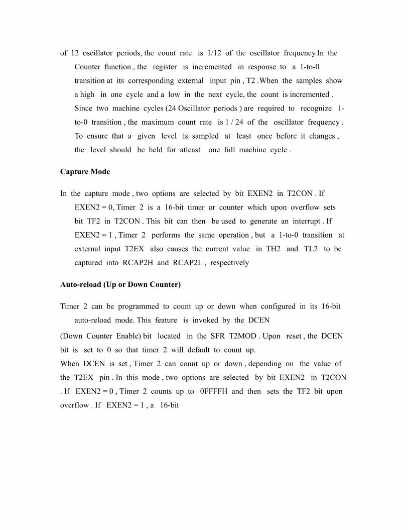
of 12 oscillator periods, the count rate is 1/12 of the oscillator frequency.In the
Counter function , the register is incremented in response to a 1-to-0
transition at its corresponding external input pin , T2 .When the samples show
a high in one cycle and a low in the next cycle, the count is incremented .
Since two machine cycles (24 Oscillator periods ) are required to recognize 1-
to-0 transition , the maximum count rate is 1 / 24 of the oscillator frequency .
To ensure that a given level is sampled at least once before it changes ,
the level should be held for atleast one full machine cycle .
Capture Mode
In the capture mode , two options are selected by bit EXEN2 in T2CON . If
EXEN2 = 0, Timer 2 is a 16-bit timer or counter which upon overflow sets
bit TF2 in T2CON . This bit can then be used to generate an interrupt . If
EXEN2 = 1 , Timer 2 performs the same operation , but a 1-to-0 transition at
external input T2EX also causes the current value in TH2 and TL2 to be
captured into RCAP2H and RCAP2L , respectively
Auto-reload (Up or Down Counter)
Timer 2 can be programmed to count up or down when configured in its 16-bit
auto-reload mode. This feature is invoked by the DCEN
(Down Counter Enable) bit located in the SFR T2MOD . Upon reset , the DCEN
bit is set to 0 so that timer 2 will default to count up.
When DCEN is set , Timer 2 can count up or down , depending on the value of
the T2EX pin . In this mode , two options are selected by bit EXEN2 in T2CON
. If EXEN2 = 0 , Timer 2 counts up to 0FFFFH and then sets the TF2 bit upon
overflow . If EXEN2 = 1 , a 16-bit

reload can be triggered either by an overflow or by a 1-to-0 transition at
external input T2EX.
Baud Rate Generator
Timer 2 is selected as the baud rate generator by setting TCLK and/or RCLK
in T2CON . Note that the baud rates for transmit and receive can be different
if Timer 2 is used for the receiver or transmitter and Timer 1 is used for the
other function .The baud rates in Modes 1 and 3 aredetermined by Timer 2’s
overflow rate according to the following equation .
Modes 1 and 3 Baud Rates =Timer 2 Overflow Rate
16
The timer operation is different for Timer 2 when it is used as a baud rate
generator .Normally ,as a timer , it increments every machine cycle (at 1/12 the
oscillator frequency).As a baud rate generator , however, it increments every
state time ( at 1/2 the oscillator frequency ) .
Timer 0
Timer 0 functions as either a timer or event counter in four modes of operation .
Timer 0 is controlled by the four lower bits of the TMOD register and bits 0, 1,
4 and 5 of the TCON register

Mode 0 ( 13-bit Timer)
Mode 0 configures timer 0 as a 13-bit timer which is set up as an
8-bit timer (TH0 register) with a modulo 32 prescaler implemented with
the lower five bits of the TL0 register . The upper three bits of TL0
register are indeterminate and should be ignored . Prescaler overflow
increments the TH0 register.
Mode 1 ( 16-bit Timer )
Mode 1 is the same as Mode 0, except that the Timer register is being run
with all 16 bits . Mode 1 configures timer 0 as a 16-bit timer with the
TH0 and TL0 registers connected in cascade . The selected input increments
the TL0 register .
Mode 2 (8-bit Timer with Auto-Reload)
Mode 2 configures timer 0 as an 8-bit timer ( TL0 register ) that automatically
reloads from the TH0 register . TL0 overflow sets TF0 flag in the TCON
register and reloads TL0 with the contents of TH0 , which is preset by
software .
Mode 3 ( Two 8-bit Timers )Mode 3 configures timer 0 so that registers TL0
and TH0 operate as separate 8-bit timers. This mode is provided for
applications requiring an additional 8-bit timer or counter .
Timer 1
Timer 1 is identical to timer 0 , except for mode 3 , which is a hold-
count mode .
Mode 3 ( Halt )

Placing Timer 1 in mode 3 causes it to halt and hold its count . This can
be used to halt Timer 1 when TR1 run control bit is not available i.e. ,
when Timer 0 is in mode 3 .
Baud Rates :
The baud rate in Mode 0 is fixed. The baud rate in Mode 2 depends
on the value of bit SMOD in Special Functio Register PCON. If SMOD
= 0 (which is its value on reset), the baud rate is 1/64 the oscillator
frequency . If SMOD = 1, the baud rate is 1/32 the oscillator frequency. In
the 89S52 , the baud rates in Modes 1 and 3 are determined by the Timer
1 overflow rate. In case of Timer 2 , these baud rates can be determined
by Timer 1 , or by Timer 2 , or by both (one for transmit and the other for
receive ).
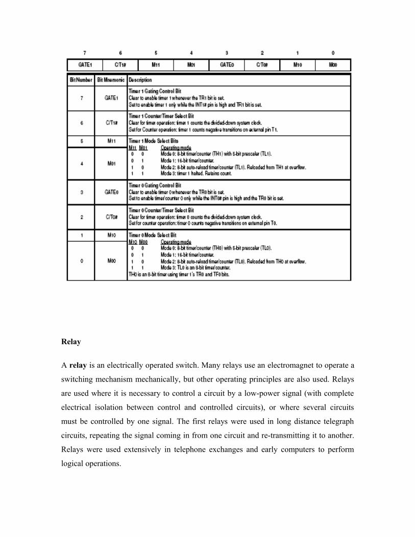
TCON REGISTER :Timer/counter Control Register

TMOD REGISTER: Timer/Counter 0 and 1 Modes
Relay
A relay is an electrically operated switch. Many relays use an electromagnet to operate a
switching mechanism mechanically, but other operating principles are also used. Relays
are used where it is necessary to control a circuit by a low-power signal (with complete
electrical isolation between control and controlled circuits), or where several circuits
must be controlled by one signal. The first relays were used in long distance telegraph
circuits, repeating the signal coming in from one circuit and re-transmitting it to another.
Relays were used extensively in telephone exchanges and early computers to perform
logical operations.

A type of relay that can handle the high power required to directly control an electric
motor or other loads is called a contactor. Solid-state relays control power circuits with
no moving parts, instead using a semiconductor device to perform switching. Relays with
calibrated operating characteristics and sometimes multiple operating coils are used to
protect electrical circuits from overload or faults; in modern electric power systems these
functions are performed by digital instruments still called "protective relays".
Basic design and operation
Simple electromechanical relay.
Small "cradle" relay often used in electronics. The "cradle" term refers to the shape of the
relay's armature.
A simple electromagnetic relay consists of a coil of wire wrapped around a soft iron core,
an iron yoke which provides a low reluctance path for magnetic flux, a movable iron
armature, and one or more sets of contacts (there are two in the relay pictured). The
armature is hinged to the yoke and mechanically linked to one or more sets of moving
contacts. It is held in place by a spring so that when the relay is de-energized there is an
air gap in the magnetic circuit. In this condition, one of the two sets of contacts in the
relay pictured is closed, and the other set is open. Other relays may have more or fewer
sets of contacts depending on their function. The relay in the picture also has a wire
connecting the armature to the yoke. This ensures continuity of the circuit between the
moving contacts on the armature, and the circuit track on the printed circuit board (PCB)
via the yoke, which is soldered to the PCB.
When an electric current is passed through the coil it generates a magnetic field that
activates the armature, and the consequent movement of the movable contact(s) either
makes or breaks (depending upon construction) a connection with a fixed contact. If the
set of contacts was closed when the relay was de-energized, then the movement opens the
contacts and breaks the connection, and vice versa if the contacts were open. When the
current to the coil is switched off, the armature is returned by a force, approximately half
as strong as the magnetic force, to its relaxed position. Usually this force is provided by a
spring, but gravity is also used commonly in industrial motor starters. Most relays are
manufactured to operate quickly. In a low-voltage application this reduces noise; in a
high voltage or current application it reduces arcing.
When the coil is energized with direct current, a diode is often placed across the coil to
dissipate the energy from the collapsing magnetic field at deactivation, which would
otherwise generate a voltage spike dangerous to semiconductor circuit components. Some
automotive relays include a diode inside the relay case. Alternatively, a contact protection
network consisting of a capacitor and resistor in series (snubber circuit) may absorb the
surge. If the coil is designed to be energized with alternating current (AC), a small copper
"shading ring" can be crimped to the end of the solenoid, creating a small out-of-phase
current which increases the minimum pull on the armature during the AC cycle.[1]
A solid-state relay uses a thyristor or other solid-state switching device, activated by the
control signal, to switch the controlled load, instead of a solenoid. An optocoupler (a
light-emitting diode (LED) coupled with a photo transistor) can be used to isolate control
and controlled circuits.
Types
Latching relay
Latching relay with permanent magnet

A latching relay has two relaxed states (bistable). These are also called "impulse",
"keep", or "stay" relays. When the current is switched off, the relay remains in its last
state. This is achieved with a solenoid operating a ratchet and cam mechanism, or by
having two opposing coils with an over-center spring or permanent magnet to hold the
armature and contacts in position while the coil is relaxed, or with a remanent core. In the
ratchet and cam example, the first pulse to the coil turns the relay on and the second pulse
turns it off. In the two coil example, a pulse to one coil turns the relay on and a pulse to
the opposite coil turns the relay off. This type of relay has the advantage that one coil
consumes power only for an instant, while it is being switched, and the relay contacts
retain this setting across a power outage. A remanent core latching relay requires a
current pulse of opposite polarity to make it change state.
Reed relay
A reed relay is a reed switch enclosed in a solenoid. The switch has a set of contacts
inside an evacuated or inert gas-filled glass tube which protects the contacts against
atmospheric corrosion; the contacts are made of magnetic material that makes them move
under the influence of the field of the enclosing solenoid. Reed relays can switch faster
than larger relays, require only little power from the control circuit, but have low
switching current and voltage ratings. In addition, the reeds can become magnetized over
time, which makes them stick 'on' even when no current is present; changing the
orientation of the reeds with respect to the solenoid's magnetic field will fix the problem.
Top, middle: reed switches, bottom: reed relay
Mercury-wetted relay
A mercury-wetted reed relay is a form of reed relay in which the contacts are wetted
with mercury. Such relays are used to switch low-voltage signals (one volt or less) where
the mercury reduces the contact resistance and associated voltage drop, for low-current
signals where surface contamination may make for a poor contact, or for high-speed
applications where the mercury eliminates contact bounce. Mercury wetted relays are

position-sensitive and must be mounted vertically to work properly. Because of the
toxicity and expense of liquid mercury, these relays are now rarely used. See also
mercury switch.
Polarized relay
A polarized relay placed the armature between the poles of a permanent magnet to
increase sensitivity. Polarized relays were used in middle 20th Century telephone
exchanges to detect faint pulses and correct telegraphic distortion. The poles were on
screws, so a technician could first adjust them for maximum sensitivity and then apply a
bias spring to set the critical current that would operate the relay.
• External links
o Schematic diagram of a polarized relay used in a teletype machine.
Machine tool relay
A machine tool relay is a type standardized for industrial control of machine tools,
transfer machines, and other sequential control. They are characterized by a large number
of contacts (sometimes extendable in the field) which are easily converted from
normally-open to normally-closed status, easily replaceable coils, and a form factor that
allows compactly installing many relays in a control panel. Although such relays once
were the backbone of automation in such industries as automobile assembly, the
programmable logic controller (PLC) mostly displaced the machine tool relay from
sequential control applications.
A relay allows circuits to be switched by electrical equipment: for example, a timer
circuit with a relay could switch power at a preset time. For many years relays were the
standard method of controlling industrial electronic systems. A number of relays could be
used together to carry out complex functions (relay logic). The principle of relay logic is
based on relays which energize and de-energize associated contacts. Relay logic is the
predecessor of ladder logic, which is commonly used in Programmable logic controllers.
Ratchet relay
This is again a clapper type relay which does not need continuous current through its coil
to retain its operation.
Contactor relay
A contactor is a very heavy-duty relay used for switching electric motors and lighting
loads, although contactors are not generally called relays. Continuous current ratings for
common contactors range from 10 amps to several hundred amps. High-current contacts
are made with alloys containing silver. The unavoidable arcing causes the contacts to
oxidize; however, silver oxide is still a good conductor.[2] Such devices are often used for
motor starters. A motor starter is a contactor with overload protection devices attached.
The overload sensing devices are a form of heat operated relay where a coil heats a bi-
metal strip, or where a solder pot melts, releasing a spring to operate auxiliary contacts.
These auxiliary contacts are in series with the coil. If the overload senses excess current
in the load, the coil is de-energized. Contactor relays can be extremely loud to operate,
making them unfit for use where noise is a chief concern.
Solid-state relay
Solid state relay with no moving parts
25 A or 40 A solid state contactors
A solid state relay (SSR) is a solid state electronic component that provides a similar
function to an electromechanical relay but does not have any moving components,
increasing long-term reliability. With early SSR's, the tradeoff came from the fact that
every transistor has a small voltage drop across it. This voltage drop limited the amount
of current a given SSR could handle. The minimum voltage drop for such a relay is equal
to the voltage drop across one transistor (~0.6-2.0 volts), and is a function of the material
used to make the transistor (typically silicon). As transistors improved, higher current

SSR's, able to handle 100 to 1,200 Amperes, have become commercially available.
Compared to electromagnetic relays, they may be falsely triggered by transients.
Solid state contactor relay
A solid state contactor is a heavy-duty solid state relay, including the necessary heat
sink, used for switching electric heaters, small electric motors and lighting loads; where
frequent on/off cycles are required. There are no moving parts to wear out and there is no
contact bounce due to vibration. They are activated by AC control signals or DC control
signals from Programmable logic controller (PLCs), PCs, Transistor-transistor logic
(TTL) sources, or other microprocessor and microcontroller controls.
Buchholz relay
A Buchholz relay is a safety device sensing the accumulation of gas in large oil-filled
transformers, which will alarm on slow accumulation of gas or shut down the transformer
if gas is produced rapidly in the transformer oil.
Forced-guided contacts relay
A forced-guided contacts relay has relay contacts that are mechanically linked together,
so that when the relay coil is energized or de-energized, all of the linked contacts move
together. If one set of contacts in the relay becomes immobilized, no other contact of the
same relay will be able to move. The function of forced-guided contacts is to enable the
safety circuit to check the status of the relay. Forced-guided contacts are also known as
"positive-guided contacts", "captive contacts", "locked contacts", or "safety relays".
Overload protection relay
Electric motors need overcurrent protection to prevent damage from over-loading the
motor, or to protect against short circuits in connecting cables or internal faults in the
motor windings.[3] One type of electric motor overload protection relay is operated by a
heating element in series with the electric motor. The heat generated by the motor current
heats a bimetallic strip or melts solder, releasing a spring to operate contacts. Where the
overload relay is exposed to the same environment as the motor, a useful though crude
compensation for motor ambient temperature is provided.
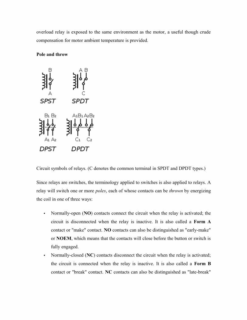
Pole and throw
Circuit symbols of relays. (C denotes the common terminal in SPDT and DPDT types.)
Since relays are switches, the terminology applied to switches is also applied to relays. A
relay will switch one or more poles, each of whose contacts can be thrown by energizing
the coil in one of three ways:
• Normally-open (NO) contacts connect the circuit when the relay is activated; the
circuit is disconnected when the relay is inactive. It is also called a Form A
contact or "make" contact. NO contacts can also be distinguished as "early-make"
or NOEM, which means that the contacts will close before the button or switch is
fully engaged.
• Normally-closed (NC) contacts disconnect the circuit when the relay is activated;
the circuit is connected when the relay is inactive. It is also called a Form B
contact or "break" contact. NC contacts can also be distinguished as "late-break"

or NCLB, which means that the contacts will stay closed until the button or
switch is fully disengaged.
• Change-over (CO), or double-throw (DT), contacts control two circuits: one
normally-open contact and one normally-closed contact with a common terminal.
It is also called a Form C contact or "transfer" contact ("break before make"). If
this type of contact utilizes a "make before break" functionality, then it is called a
Form D contact.
The following designations are commonly encountered:
• SPST – Single Pole Single Throw. These have two terminals which can be
connected or disconnected. Including two for the coil, such a relay has four
terminals in total. It is ambiguous whether the pole is normally open or normally
closed. The terminology "SPNO" and "SPNC" is sometimes used to resolve the
ambiguity.
• SPDT – Single Pole Double Throw. A common terminal connects to either of two
others. Including two for the coil, such a relay has five terminals in total.
• DPST – Double Pole Single Throw. These have two pairs of terminals.
Equivalent to two SPST switches or relays actuated by a single coil. Including
two for the coil, such a relay has six terminals in total. The poles may be Form A
or Form B (or one of each).
• DPDT – Double Pole Double Throw. These have two rows of change-over
terminals. Equivalent to two SPDT switches or relays actuated by a single coil.
Such a relay has eight terminals, including the coil.
The "S" or "D" may be replaced with a number, indicating multiple switches connected to
a single actuator. For example 4PDT indicates a four pole double throw relay (with 14
terminals).
EN 50005 are among applicable standards for relay terminal numbering; a typical EN
50005-compliant SPDT relay's terminals would be numbered 11, 12, 14, A1 and A2 for
the C, NC, NO, and coil connections, respectively.

Applications
Relays are used to and for:
• Amplify a digital signal, switching a large amount of power with a small
operating power. Some special cases are:
o A telegraph relay, repeating a weak signal received at the end of a long
wire
o Controlling a high-voltage circuit with a low-voltage signal, as in some
types of modems or audio amplifiers,
o Controlling a high-current circuit with a low-current signal, as in the
starter solenoid of an automobile,
• Detect and isolate faults on transmission and distribution lines by opening and
closing circuit breakers (protection relays),
A DPDT AC coil relay with "ice cube" packaging
• Isolate the controlling circuit from the controlled circuit when the two are at
different potentials, for example when controlling a mains-powered device from a
low-voltage switch. The latter is often applied to control office lighting as the low
voltage wires are easily installed in partitions, which may be often moved as
needs change. They may also be controlled by room occupancy detectors to
conserve energy,
• Logic functions. For example, the boolean AND function is realised by
connecting normally open relay contacts in series, the OR function by connecting
normally open contacts in parallel. The change-over or Form C contacts perform
the XOR (exclusive or) function. Similar functions for NAND and NOR are
accomplished using normally closed contacts. The Ladder programming language
is often used for designing relay logic networks.

o The application of Boolean Algebra to relay circuit design was formalized
by Claude Shannon in A Symbolic Analysis of Relay and Switching
Circuits
o Early computing. Before vacuum tubes and transistors, relays were used as
logical elements in digital computers. See electro-mechanical computers
such as ARRA (computer), Harvard Mark II, Zuse Z2, and Zuse Z3.
o Safety-critical logic. Because relays are much more resistant than
semiconductors to nuclear radiation, they are widely used in safety-critical
logic, such as the control panels of radioactive waste-handling machinery.
• Time delay functions. Relays can be modified to delay opening or delay closing a
set of contacts. A very short (a fraction of a second) delay would use a copper
disk between the armature and moving blade assembly. Current flowing in the
disk maintains magnetic field for a short time, lengthening release time. For a
slightly longer (up to a minute) delay, a dashpot is used. A dashpot is a piston
filled with fluid that is allowed to escape slowly. The time period can be varied by
increasing or decreasing the flow rate. For longer time periods, a mechanical
clockwork timer is installed.
• Vehicle battery isolation. A 12v relay is often used to isolate any second battery
in cars, 4WDs, RVs and boats.
• Switching to a standby power supply.
Relay application considerations
A large relay with two coils and many sets of contacts, used in an old telephone
switching system.
Several 30-contact relays in "Connector" circuits in mid 20th century 1XB switch and
5XB switch telephone exchanges; cover removed on one

Selection of an appropriate relay for a particular application requires evaluation of many
different factors:
• Number and type of contacts – normally open, normally closed, (double-throw)
• Contact sequence – "Make before Break" or "Break before Make". For example,
the old style telephone exchanges required Make-before-break so that the
connection didn't get dropped while dialing the number.
• Rating of contacts – small relays switch a few amperes, large contactors are rated
for up to 3000 amperes, alternating or direct current
• Voltage rating of contacts – typical control relays rated 300 VAC or 600 VAC,
automotive types to 50 VDC, special high-voltage relays to about 15 000 V
• Operating lifetime, useful life - the number of times the relay can be expected to
operate reliably. There is both a mechanical life and a contact life; the contact life
is naturally affected by the kind of load being switched.
• Coil voltage – machine-tool relays usually 24 VAC, 120 or 250 VAC, relays for
switchgear may have 125 V or 250 VDC coils, "sensitive" relays operate on a few
milliamperes
• Coil current - including minimum current required to operate reliably and
minimum current to hold. Also effects of power dissipation on coil temperature at
various duty cycles.
• Package/enclosure – open, touch-safe, double-voltage for isolation between
circuits, explosion proof, outdoor, oil and splash resistant, washable for printed
circuit board assembly
• Operating environment - minimum and maximum operating temperatures and
other environmental considerations such as effects of humidity and salt
• Assembly – Some relays feature a sticker that keeps the enclosure sealed to allow
PCB post soldering cleaning, which is removed once assembly is complete.
• Mounting – sockets, plug board, rail mount, panel mount, through-panel mount,
enclosure for mounting on walls or equipment
• Switching time – where high speed is required

• "Dry" contacts – when switching very low level signals, special contact materials
may be needed such as gold-plated contacts
• Contact protection – suppress arcing in very inductive circuits
• Coil protection – suppress the surge voltage produced when switching the coil
current
• Isolation between coil contacts
• Aerospace or radiation-resistant testing, special quality assurance
• Expected mechanical loads due to acceleration – some relays used in aerospace
applications are designed to function in shock loads of 50 g or more
• Accessories such as timers, auxiliary contacts, pilot lamps, test buttons
• Regulatory approvals
• Stray magnetic linkage between coils of adjacent relays on a printed circuit board.
There are many considerations involved in the correct selection of a control relay for a
particular application. These considerations include factors such as speed of operation,
sensitivity, and hysteresis. Although typical control relays operate in the 5 ms to 20 ms
range, relays with switching speeds as fast as 100 us are available. Reed relays which are
actuated by low currents and switch fast are suitable for controlling small currents.
As for any switch, the current through the relay contacts (unrelated to the current through
the coil) must not exceed a certain value to avoid damage. In the particular case of high-
inductance circuits such as motors other issues must be addressed. When a power source
is connected to an inductance, an input surge current which may be several times larger
than the steady current exists. When the circuit is broken, the current cannot change
instantaneously, which creates a potentially damaging spark across the separating
contacts.
Consequently for relays which may be used to control inductive loads we must specify
the maximum current that may flow through the relay contacts when it actuates, the make
rating; the continuous rating; and the break rating. The make rating may be several times
larger than the continuous rating, which is itself larger than the break rating.

Derating factors
Control relays should not be operated above rated temperature because of resulting
increased degradation and fatigue. Common practice is to derate 20 degrees Celsius from
the maximum rated temperature limit. Relays operating at rated load are also affected by
their environment. Oil vapors may greatly decrease the
contact tip life, and dust or dirt may cause the tips to
burn before their normal life expectancy. Control relay
life cycle varies from 50,000 to over one million
cycles depending on the electrical loads of the
contacts, duty cycle, application, and the extent to which the relay is derated. When a
control relay is operating at its derated value, it is controlling a lower value of current
than its maximum make and break ratings. This is often done to extend the operating life
of the control relay. The table lists the relay derating factors for typical industrial control
applications.
Undesired arcing
Without adequate contact protection, the occurrence of electric current arcing causes
significant degradation of the contacts in relays, which suffer significant and visible
damage. Every time a relay transitions either from a closed to an open state (break arc) or
from an open to a closed state (make arc & bounce arc), under load, an electrical arc can
occur between the two contact points (electrodes) of the relay. The break arc is typically
more energetic and thus more destructive.
The heat energy contained in the resulting electrical arc is very high (tens of thousands of
degrees Fahrenheit), causing the metal on the contact surfaces to melt, pool and migrate
with the current. The extremely high temperature of the arc cracks the surrounding gas
molecules creating ozone, carbon monoxide, and other compounds. The arc energy
slowly destroys the contact metal, causing some material to escape into the air as fine
particulate matter. This very activity causes the material in the contacts to degrade
quickly, resulting in device failure. This contact degradation drastically limits the overall
Type of load % of rated valueResistive 75Inductive 35Motor 20Filament 10Capacitive 75

life of a relay to a range of about 10,000 to 100,000 operations, a level far below the
mechanical life of the same device, which can be in excess of 20 million operations.[4]
Protective relays
For protection of electrical apparatus and transmission lines, electromechanical relays
with accurate operating characteristics were used to detect overload, short-circuits, and
other faults. While many such relays remain in use, digital devices now provide
equivalent protective functions.
Railway signalling
UK Q-style signalling relay and base.
Railway signalling relays are very big and cumbersome compared to the mostly small
voltages (less than 120 V) and currents (perhaps 100 mA) that they switch. Contacts are
widely spaced to prevent dangerous flashovers and short circuits over a lifetime that may
exceed fifty years. BR930 series plug-in relays are widely used on railways following
British practice. These are 120 mm high, 180 mm deep and 56 mm wide and weigh about
1400 g, and can have up to 16 separate contacts, say 12 make and 4 break contacts.
Since rail signal circuits must be highly reliable, special techniques are used to detect and
prevent failures in the relay system. To protect against false feeds, double switching relay
contacts are often used on both the positive and negative side of a circuit, so that two
false feeds are needed to cause a false signal. Not all relay circuits can be proved so there
is reliance on construction features such as carbon to silver contacts to resist lightning
induced contact welding and to provide AC immunity.
Opto-isolators are also used in some instances with railway signalling, especially where
only a single contact is to be switched.
History
In 1835, the relay was invented by American scientist Joseph Henry to improve his
version of the electrical telegraph, developed in 1831.[5][6]
A ‘relay’ or ‘repeater’ of Edward Davy of 1837/1838 was used in his electric telegraph.[citation needed]
A simple device, which we now call a relay, was included in the original 1840 telegraph
patent of Samuel Morse. The mechanism described acted as a digital amplifier, repeating
the telegraph signal, and thus allowing signals to be propagated as far as desired. This
overcame the problem of limited range of earlier telegraphy schemes.
GSM (Global System for Mobile communications)
Introduction:
GSM (Global System for Mobile communications) is a cellular network, which means
that mobile phones connect to it by searching for cells in the immediate vicinity. GSM
networks operate in four different frequency ranges. Most GSM networks operate in the
900 MHz or 1800 MHz bands. Some countries in the Americas use the 850 MHz and
1900 MHz bands because the 900 and 1800 MHz frequency bands were already
allocated.
The rarer 400 and 450 MHz frequency bands are assigned in some countries, where these
frequencies were previously used for first-generation systems.
GSM-900 uses 890–915 MHz to send information from the mobile station to the base
station (uplink) and 935–960 MHz for the other direction (downlink), providing 124 RF
channels (channel numbers 1 to 124) spaced at 200 kHz. Duplex spacing of 45 MHz is
used. In some countries the GSM-900 band has been extended to cover a larger frequency
range. This 'extended GSM', E-GSM, uses 880–915 MHz (uplink) and 925–960 MHz
(downlink), adding 50 channels (channel numbers 975 to 1023 and 0) to the original

GSM-900 band. Time division multiplexing is used to allow eight full-rate or sixteen
half-rate speech channels per radio frequency channel. There are eight radio timeslots
(giving eight burst periods) grouped into what is called a TDMA frame. Half rate
channels use alternate frames in the same timeslot. The channel data rate is
270.833 kbit/s, and the frame duration is 4.615 ms.
GSM Advantages:
GSM also pioneered a low-cost, to the network carrier, alternative to voice calls, the
Short t message service (SMS, also called "text messaging"), which is now supported on
other mobile standards as well. Another advantage is that the standard includes one
worldwide Emergency telephone number, 112. This makes it easier for international
travelers to connect to emergency services without knowing the local emergency number.
The GSM Network:
GSM provides recommendations, not requirements. The GSM specifications define the
functions and interface requirements in detail but do not address the hardware. The GSM
network is divided into three major systems: the switching system (SS), the base station
system (BSS), and the operation and support system (OSS).

The Switching System:
The switching system (SS) is responsible for performing call processing and subscriber-
related functions. The switching system includes the following functional units.
• Home location register (HLR): The HLR is a database used for storage and
management of subscriptions. The HLR is considered the most important
database, as it stores permanent data about subscribers, including a subscriber's
service profile, location information, and activity status. When an individual buys
a subscription from one of the PCS operators, he or she is registered in the HLR
of that operator.
• Mobile services switching center (MSC): The MSC performs the telephony
switching functions of the system. It controls calls to and from other telephone
and data systems. It also performs such functions as toll ticketing, network
interfacing, common channel signaling, and others.
• Visitor location register (VLR): The VLR is a database that contains temporary
information about subscribers that is needed by the MSC in order to service
visiting subscribers. The VLR is always integrated with the MSC. When a mobile
station roams into a new MSC area, the VLR connected to that MSC will request
data about the mobile station from the HLR. Later, if the mobile station makes a
call, the VLR will have the information needed for call setup without having to
interrogate the HLR each time.
• Authentication center (AUC): A unit called the AUC provides authentication
and encryption parameters that verify the user's identity and ensure the
confidentiality of each call. The AUC protects network operators from different
types of fraud found in today's cellular world.
• Equipment identity register (EIR): The EIR is a database that contains
information about the identity of mobile equipment that prevents calls from
stolen, unauthorized, or defective mobile stations. The AUC and EIR are
implemented as stand-alone nodes or as a combined AUC/EIR node.
The Base Station System (BSS):
All radio-related functions are performed in the BSS, which consists of base station
controllers (BSCs) and the base transceiver stations (BTSs).
• BSC: The BSC provides all the control functions and physical links between the
MSC and BTS. It is a high-capacity switch that provides functions such as
handover, cell configuration data, and control of radio frequency (RF) power
levels in base transceiver stations. A number of BSCs are served by an MSC.
• BTS: The BTS handles the radio interface to the mobile station. The BTS is the
radio equipment (transceivers and antennas) needed to service each cell in the
network. A group of BTSs are controlled by a BSC.
The Operation and Support System
The operations and maintenance center (OMC) is connected to all equipment in the
switching system and to the BSC. The implementation of OMC is called the operation
and support system (OSS). The OSS is the functional entity from which the network
operator monitors and controls the system. The purpose of OSS is to offer the customer
cost-effective support for centralized, regional and local operational and maintenance
activities that are required for a GSM network. An important function of OSS is to
provide a network overview and support the maintenance activities of different operation
and maintenance organizations.
Additional Functional Elements
• Message center (MXE): The MXE is a node that provides integrated voice, fax,
and data messaging. Specifically, the MXE handles short message service, cell
broadcast, voice mail, fax mail, e-mail, and notification.
• Mobile service node (MSN): The MSN is the node that handles the mobile
intelligent network (IN) services.
• Gateway mobile services switching center (GMSC): A gateway is a node used
to interconnect two networks. The gateway is often implemented in an MSC. The
MSC is then referred to as the GMSC.
• GSM inter-working unit (GIWU): The GIWU consists of both hardware and
software that provides an interface to various networks for data communications.
Through the GIWU, users can alternate between speech and data during the same
call. The GIWU hardware equipment is physically located at the MSC/VLR.
GSM Network Areas:

The GSM network is made up of geographic areas. As shown in bellow figure, these
areas include cells, location areas (LAs), MSC/VLR service areas, and public land mobile
network (PLMN) areas.
Location Areas:
The cell is the area given radio coverage by one base transceiver station. The GSM
network identifies each cell via the cell global identity (CGI) number assigned to each
cell. The location area is a group of cells. It is the area in which the subscriber is paged.
Each LA is served by one or more base station controllers, yet only by a single MSC
Each LA is assigned a location area identity (LAI) number.
MSC/VLR service areas:
An MSC/VLR service area represents the part of the GSM network that is covered by one
MSC and which is reachable, as it is registered in the VLR of the MSC.
PLMN service areas:
The PLMN service area is an area served by one network operator.
GSM Specifications:

Specifications for different personal communication services (PCS) systems vary among the different PCS networks. Listed below is a description of the specifications and characteristics for GSM.
• Frequency band: The frequency range specified for GSM is 1,850 to 1,990 MHz
(mobile station to base station).
• Duplex distance: The duplex distance is 80 MHz. Duplex distance is the distance
between the uplink and downlink frequencies. A channel has two frequencies, 80
MHz apart.
• Channel separation: The separation between adjacent carrier frequencies. In
GSM, this is 200 kHz.
• Modulation: Modulation is the process of sending a signal by changing the
characteristics of a carrier frequency. This is done in GSM via Gaussian minimum
shift keying (GMSK).
• Transmission rate: GSM is a digital system with an over-the-air bit rate of 270
kbps.
• Access method: GSM utilizes the time division multiple access (TDMA) concept.
TDMA is a technique in which several different calls may share the same carrier.
Each call is assigned a particular time slot.
• Speech coder: GSM uses linear predictive coding (LPC). The purpose of LPC is
to reduce the bit rate. The LPC provides parameters for a filter that mimics the
vocal tract. The signal passes through this filter, leaving behind a residual signal.
Speech is encoded at 13 kbps.
GSM Subscriber Services:
Dual-tone multifrequency (DTMF): DTMF is a tone signaling scheme often used for
various control purposes via the telephone network, such as remote control of an
answering machine. GSM supports full-originating DTMF.
Facsimile group III—GSM supports CCITT Group 3 facsimile. As standard fax
machines are designed to be connected to a telephone using analog signals, a special fax

converter connected to the exchange is used in the GSM system. This enables a GSM–
connected fax to communicate with any analog fax in the network.
Short message services: A convenient facility of the GSM network is the short message
service. A message consisting of a maximum of 160 alphanumeric characters can be sent
to or from a mobile station. This service can be viewed as an advanced form of
alphanumeric paging with a number of advantages. If the subscriber's mobile unit is
powered off or has left the coverage area, the message is stored and offered back to the
subscriber when the mobile is powered on or has reentered the coverage area of the
network. This function ensures that the message will be received.
Cell broadcast: A variation of the short message service is the cell broadcast facility. A
message of a maximum of 93 characters can be broadcast to all mobile subscribers in a
certain geographic area. Typical applications include traffic congestion warnings and
reports on accidents.
Voice mail: This service is actually an answering machine within the network, which is
controlled by the subscriber. Calls can be forwarded to the subscriber's voice-mail box
and the subscriber checks for messages via a personal security code.
Fax mail: With this service, the subscriber can receive fax messages at any fax machine.
The messages are stored in a service center from which they can be retrieved by the
subscriber via a personal security code to the desired fax number
Supplementary Services:
GSM supports a comprehensive set of supplementary services that can complement and
support both telephony and data services.
Call forwarding: This service gives the subscriber the ability to forward incoming calls
to another number if the called mobile unit is not reachable, if it is busy, if there is no
reply, or if call forwarding is allowed unconditionally.

Barring of outgoing calls: This service makes it possible for a mobile subscriber to
prevent all outgoing calls.
Barring of incoming calls: This function allows the subscriber to prevent incoming
calls. The following two conditions for incoming call barring exist: baring of all
incoming calls and barring of incoming calls when roaming outside the home PLMN.
Advice of charge (AoC): The AoC service provides the mobile subscriber with an
estimate of the call charges. There are two types of AoC information: one that provides
the subscriber with an estimate of the bill and one that can be used for immediate
charging purposes. AoC for data calls is provided on the basis of time measurements.
Call hold: This service enables the subscriber to interrupt an ongoing call and then
subsequently reestablish the call. The call hold service is only applicable to normal
telephony.
Call waiting: This service enables the mobile subscriber to be notified of an incoming
call during a conversation. The subscriber can answer, reject, or ignore the incoming call.
Call waiting is applicable to all GSM telecommunications services using a circuit-
switched connection.
Multiparty service: The multiparty service enables a mobile subscriber to establish a
multiparty conversation—that is, a simultaneous conversation between three and six
subscribers. This service is only applicable to normal telephony.
Calling line identification presentation/restriction: These services supply the called
party with the integrated services digital network (ISDN) number of the calling party.
The restriction service enables the calling party to restrict the presentation. The restriction
overrides the presentation.
Closed user groups (CUGs): CUGs are generally comparable to a PBX. They are a
group of subscribers who are capable of only calling themselves and certain numbers
Main AT commands:
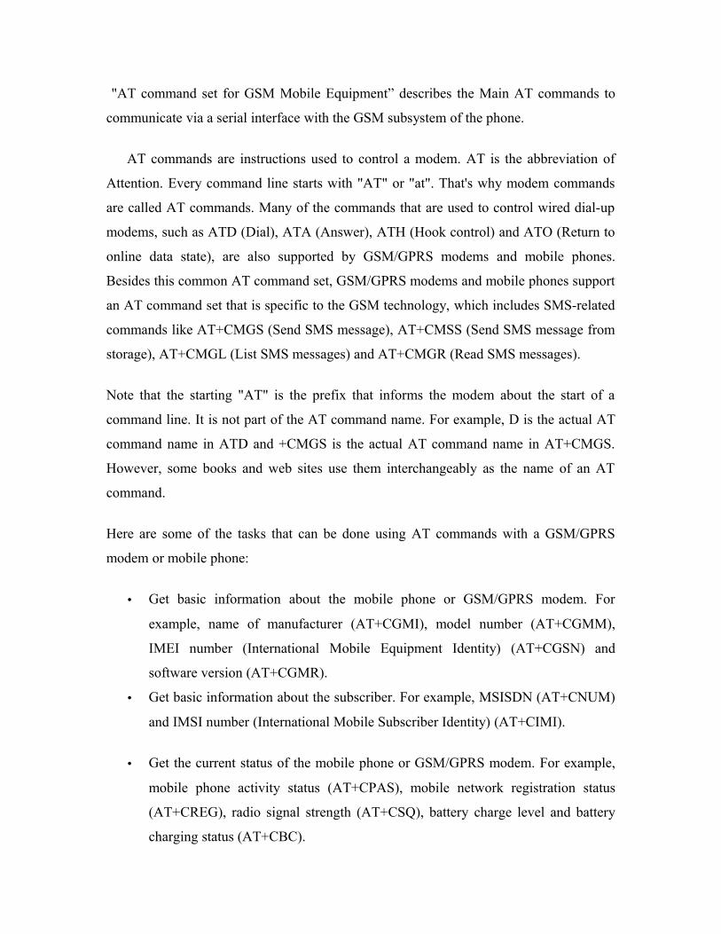
"AT command set for GSM Mobile Equipment” describes the Main AT commands to
communicate via a serial interface with the GSM subsystem of the phone.
AT commands are instructions used to control a modem. AT is the abbreviation of
Attention. Every command line starts with "AT" or "at". That's why modem commands
are called AT commands. Many of the commands that are used to control wired dial-up
modems, such as ATD (Dial), ATA (Answer), ATH (Hook control) and ATO (Return to
online data state), are also supported by GSM/GPRS modems and mobile phones.
Besides this common AT command set, GSM/GPRS modems and mobile phones support
an AT command set that is specific to the GSM technology, which includes SMS-related
commands like AT+CMGS (Send SMS message), AT+CMSS (Send SMS message from
storage), AT+CMGL (List SMS messages) and AT+CMGR (Read SMS messages).
Note that the starting "AT" is the prefix that informs the modem about the start of a
command line. It is not part of the AT command name. For example, D is the actual AT
command name in ATD and +CMGS is the actual AT command name in AT+CMGS.
However, some books and web sites use them interchangeably as the name of an AT
command.
Here are some of the tasks that can be done using AT commands with a GSM/GPRS
modem or mobile phone:
• Get basic information about the mobile phone or GSM/GPRS modem. For
example, name of manufacturer (AT+CGMI), model number (AT+CGMM),
IMEI number (International Mobile Equipment Identity) (AT+CGSN) and
software version (AT+CGMR).
• Get basic information about the subscriber. For example, MSISDN (AT+CNUM)
and IMSI number (International Mobile Subscriber Identity) (AT+CIMI).
• Get the current status of the mobile phone or GSM/GPRS modem. For example,
mobile phone activity status (AT+CPAS), mobile network registration status
(AT+CREG), radio signal strength (AT+CSQ), battery charge level and battery
charging status (AT+CBC).

• Establish a data connection or voice connection to a remote modem (ATD, ATA,
etc).
• Send and receive fax (ATD, ATA, AT+F*).
• Send (AT+CMGS, AT+CMSS), read (AT+CMGR, AT+CMGL), write
(AT+CMGW) or delete (AT+CMGD) SMS messages and obtain notifications of
newly received SMS messages (AT+CNMI).
• Read (AT+CPBR), write (AT+CPBW) or search (AT+CPBF) phonebook entries.
• Perform security-related tasks, such as opening or closing facility locks
(AT+CLCK), checking whether a facility is locked (AT+CLCK) and changing
passwords (AT+CPWD).
(Facility lock examples: SIM lock [a password must be given to the SIM card
every time the mobile phone is switched on] and PH-SIM lock [a certain SIM
card is associated with the mobile phone. To use other SIM cards with the mobile
phone, a password must be entered.])
• Control the presentation of result codes / error messages of AT commands. For
example, you can control whether to enable certain error messages (AT+CMEE)
and whether error messages should be displayed in numeric format or verbose
format (AT+CMEE=1 or AT+CMEE=2).
• Get or change the configurations of the mobile phone or GSM/GPRS modem. For
example, change the GSM network (AT+COPS), bearer service type
(AT+CBST), radio link protocol parameters (AT+CRLP), SMS center address
(AT+CSCA) and storage of SMS messages (AT+CPMS).
• Save and restore configurations of the mobile phone or GSM/GPRS modem. For
example, save (AT+CSAS) and restore (AT+CRES) settings related to SMS
messaging such as the SMS center address.

MAX 232
Introduction:
A standard serial interface for PC, RS232C, requires negative logic, i.e., logic 1 is
-3V to -12V and logic 0 is +3V to +12V. To convert TTL logic, say, TxD and RxD pins
of the microcontroller thus need a converter chip. A MAX232 chip has long been using in
many microcontrollers boards. It is a dual RS232 receiver / transmitter that meets all
RS232 specifications while using only +5V power supply. It has two onboard charge
pump voltage converters which generate +10V to -10V power supplies from a single 5V
supply. It has four level translators, two of which are RS232 transmitters that convert
TTL/CMOS input levels into +9V RS232 outputs. The other two level translators are
RS232 receivers that convert RS232 input to 5V. Typical MAX232 circuit is shown
below.

Feachers:
1. Operates With Single 5-V Power Supply
2.LinBiCMOSE Process Technology
3.Two Drivers and Two Receivers
4.±30-V Input Levels
5.Low Supply Current . 8 mA Typical
6.Meets or Exceeds TIA/EIA-232-F and ITU
Recommendation V.28
7.Designed to be Interchangeable With
Maxim MAX232
8.Applications
TIA/EIA-232-F
Battery-Powered Systems
Terminals
Modems
Computers
9.ESD Protection Exceeds 2000 V Per
MIL-STD-883, Method 3015
10.Package Options Include Plastic
Small-Outline (D, DW) Packages and
Standard Plastic (N) DIPs
Cicuit connections:
A standard serial interfacing for PC, RS232C, requires negative logic, i.e., logic '1' is
-3V to -12V and logic '0' is +3V to +12V. To convert a TTL logic, say, TxD and RxD
pins of the uC chips, thus need a converter chip. A MAX232 chip has long been using in
many uC boards. It provides 2-channel RS232C port and requires external 10uF pacitors.
Carefully check the polarity of capacitor when soldering the board. A DS275 however,
no need external capacitor and smaller. Either circuit can be used without any problems.
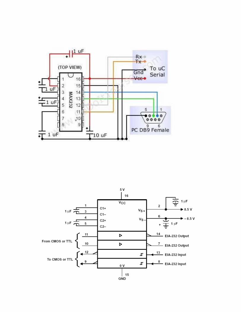

Configuring the Simulator
Open the Keil µVision2
Go to Project – Open Project and browse for Hello in Ch03_00 in Pont and open it.
Go to Project – Select Device for Target ‘Target1’
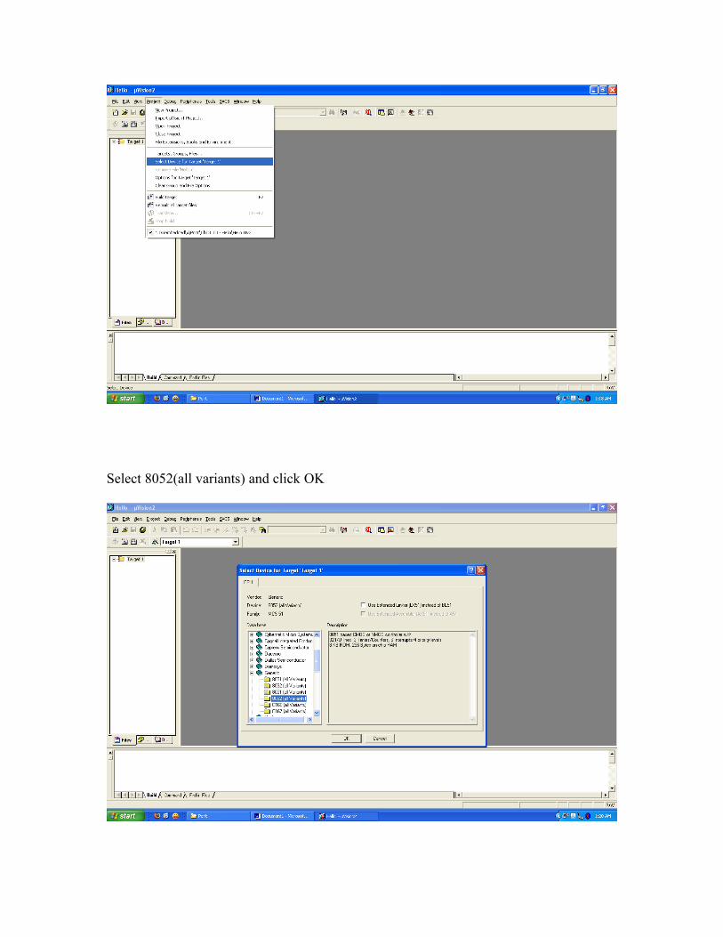
Select 8052(all variants) and click OK
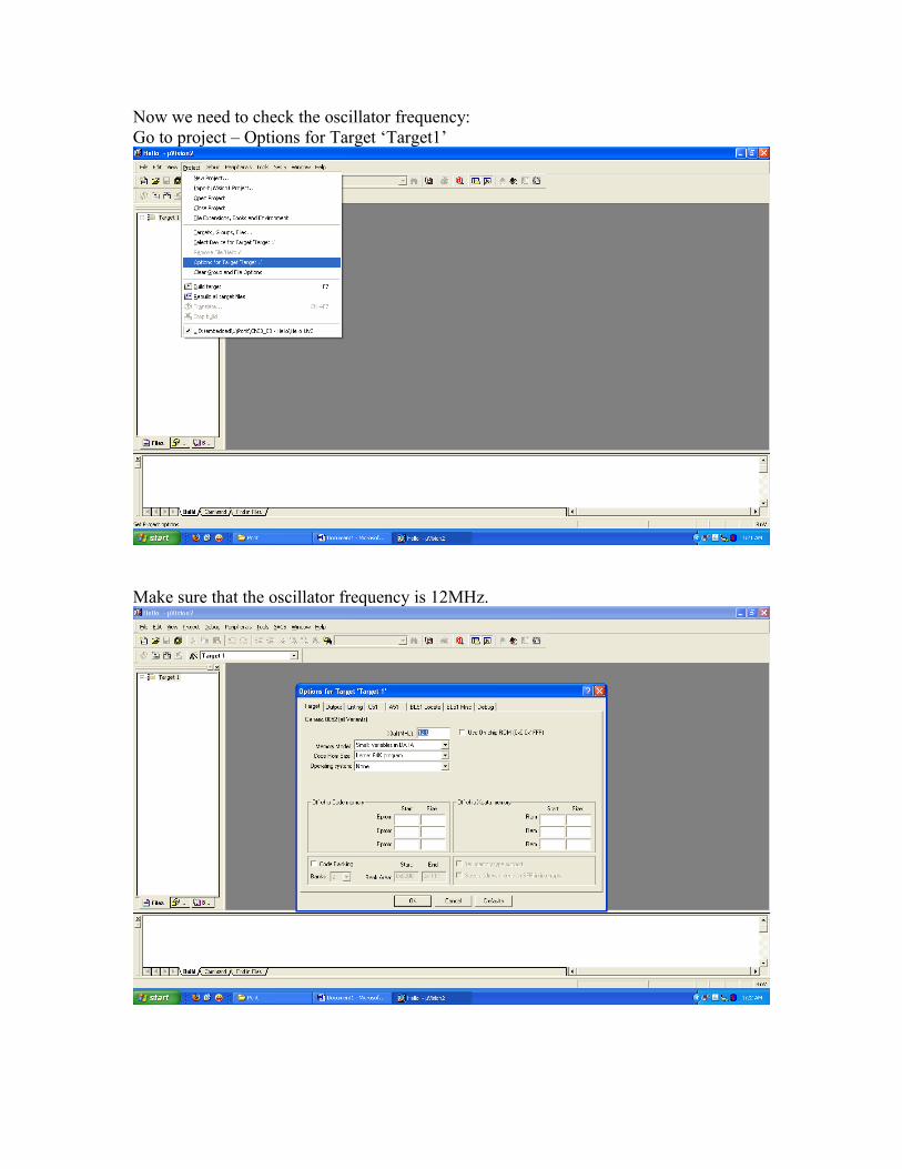
Now we need to check the oscillator frequency:Go to project – Options for Target ‘Target1’
Make sure that the oscillator frequency is 12MHz.

Building the Target
Build the target as illustrated in the figure below
Running the SimulationHaving successfully built the target, we are now ready to start the debug session and run the simulator.First start a debug session

The flashing LED we will view will be connected to Port 1. We therefore want to observe the activity on this port
To ensure that the port activity is visible, we need to start the ‘periodic window update’ flag

Go to Debug - Go
While the simulation is running, view the performance analyzer to check the delay durations.

Go to Debug – Performance Analyzer and click on it

Double click on DELAY_LOOP_Wait in Function Symbols: and click Define button
Bibliography:
The 8051 Micro controller and Embedded Systems Muhammad Ali Mazidi Janice Gillispie Mazidi
The 8051 Micro controller Architecture, Programming & Applications
Kenneth J.Ayala
Fundamentals of Micro processors and Micro computers
B.Ram
Micro processor Architecture, Programming & Applications
Ramesh S.Gaonkar
Electronic Components
D.V.Prasad

References on the Web:
www.national.comwww.atmel.comwww.microsoftsearch.comwww.geocities.com