home automation & control john errington. why home automation? your security system knows all...
TRANSCRIPT

HOME AUTOMATION & CONTROL
John Errington

WHY HOME AUTOMATION?
Your security system knows all about your occupancy of the house. With a little more development it can build an intelligent ‘expert system’ to predict your usage, and for example turn the alarm on if you forget.
Your central heating programmer knows the standards of comfort you expect – but doesn’t know which rooms are in use.
By linking just these two you could achieve a reduction in fuel costs and a better match to your requirements.

APPLICATIONS
The applications are limited only by your imagination: Turning lights down / off at night. Operating outside lights Turning lights or radio on / off when someone
approaches the house, simulating occupancy Operating television, hot water heater, kettle, toaster
etc. ready for your use. Optimizing use of low cost electricity (economy 7) Working with intelligent electrical white goods e.g.
washing machine, fridge, microwave etc.

WHAT IS HOME AUTOMATION?
Home automation deals with providing a network in the house which links
computers & peripheral equipment, smart chip bearing household appliances
(white goods) e.g. dish washers, washing machines, microwaves etc., and
sub-systems like Heating, Ventilation, Air-conditioning (HVAC), and security systems.

Showing some applications of X-10 and European Home System (EHS) for home automation

ADVANTAGES OF HOME AUTOMATION
Flexibility & Convenience Security Cost Saving Security Remote Control

EXAMPLE OF APPLICATIONS FOR HOME AUTOMATION SYSTEM

HISTORY & EARLY DEVELOPMENTS
Earliest home control systems were proposed by Hitachi & Matsushita in 1978.
First home automation blue prints and demonstrations held by Japanese Electrical Appliance manufacturers like Sanyo, Sony, Toshiba etc.
Honeywell’s first demonstration house started in 1978. American X 10 system appeared in 1979. Two rival programs CEBus and Smart House started in the early 1980’s
in the US. GE reported their multimedia home bus signaling protocol Homenet in
1983. Total Home system launched in 1992. GIS, Home Automation Ltd. MK Electric took the initiative in Europe.

THE NEED FOR PROTOCOLS AND STANDARDISATION
A definite set of rules were needed for products to communicate with each other and some sort of control unit was needed to control these various products.
Resolving Contention Integrating various transmission media. System Architecture – two alternatives
Centralized Control Distributed Control

HOME AUTOMATION AROUND THE WORLD

TYPES OF HOME AUTOMATION SYSTEMS
PC-based system: Requires a PC to be running at all times. Dedicated PC Shared PC
Standalone system: Runs without a PC, although may use a PC for programming
Hybrid system: Runs without a PC, but uses PC to add more functions.
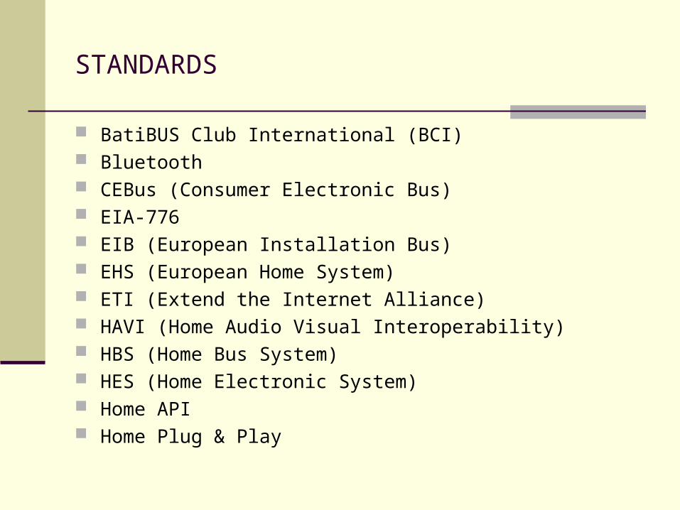
STANDARDS
BatiBUS Club International (BCI) Bluetooth CEBus (Consumer Electronic Bus) EIA-776 EIB (European Installation Bus) EHS (European Home System) ETI (Extend the Internet Alliance) HAVI (Home Audio Visual Interoperability) HBS (Home Bus System) HES (Home Electronic System) Home API Home Plug & Play

STANDARDS - CONTINUED
Home Plug Alliance Home PNA (Home Phoneline and network Alliance) Home RF (Home Radia Frequency working Group) JINI (The Jini Community) LonMark Interoperability Association OSGI (Open Service Gateway Initiative) Wireless Ethernet Compatibility Alliance Upnp (Universal Plug and Play) VESA (Video Electronics Standards Assoc.)
PROPRIETARY SPECIFICATIONS HomeConnex-Peracom Networks , No New Wires- Intellon
Corp, Lonworks-Echelon Corp., Sharewave-Sharewave Inc. , X-10-X10 Inc.

X-10: THE FATHER OF POWERLINE HOME AUTOMATION PROTOCOLS
X-10 is a communications protocol for remote control of electrical devices. Consists of X-10 transmitters and receivers which communicate over the existing standard household wiring.
X-10 is a trademark of X-10 USA and of X-10 Home Controls Incorporated (Canada).
X-10 PLC technology was initially developed between 1976 and 1978 by engineers at Pico Electronics Ltd. in Scotland. A merger with BSR International established X-10 Ltd. in 1978.

X-10 SPECIFICATIONS
Transmitters and receivers plug into standard electrical outlets or are hardwired into electrical boxes.
They have three main functions(turn on, turn off and dim) Simplest Transmitter: A small control box with buttons to select the
unit to be controlled and to select the control command to be sent. Programmable units having on board timers to select times at which
control signals are sent. Programming is done with on board buttons or through PC.
Special purpose X10 transmitters respond to motion, light or DTMF (telephone) tones
Simplest Receiver: A small module plugged into an electrical outlet provides controlled power to the controlled device. It has two dials to set the unit ID code on it.
A relay inside switches on and off in response to X-10 commands directed to it. A lamp module has a triac instead of a relay.

Examples of X-10 devices

X-10: LIMITING RANGE OF TRANSMISSION
The next slide shows how X10 uses bursts of 120kHz signal superimposed onto the house mains supply, shown as one of the three supply phases.
This means interference can only occur with one in three neighbouring houses.
X10 also uses a house code (A – P) that can be adjusted to be different to the remaining neighbours.

X-10: Signals are sent at the zero crossing for each phase of the electricity supply ensuring successful communication

X-10 SPECIFICATIONS CONTINUED
X-10 specifies a total of 256 different addresses.
Each transmitter is selectable by a unique house code out of a total of 16 house codes (A-P).
Each transmitter can further handle a total of 16 receiving units corresponding to 16 different unit codes (1-16)

X-10: INTERFACE WITH A COMPUTER
The PC can control the X-10 modules via the CP290 Home Control Interface.
Other X10 modules to interface computers directly to the power line are PL513 (send only) W523 (send & receive) and PLIX (Power Line interface to X-10)

X-10 TRANSMISSION DETAILS
Each ONE bit in a legitimate X 10 transmission is a 1 millisecond(ms) pulse code modulated burst of 120KHz on the AC line and each ZERO is the absence of such a burst. The burst is sent three times for each bit once at each AC zero crossing( accounting for zero crossing in 3-phase).
Each bit is sent both true and complemented and each code sequence is sent twice to overcome the noise over the line.
Bit sequence for a typical X10 transmission:
1 1 1 0 H8 /H8 H4 /H4 H2 /H2 H1 /H1 D8 /D8 D4 /D4 D2 /D2 D1 /D1 F /F
(start) (House code) (Unit/Function code)

X-10: Example of transmitted signal
Leader 1110 House code (A – P)
D = 0011 Unit code (1 – 16)
13 = 1100 Function (1 on or 0 off)
on = 1
House and unit codes
A 1 0000 I 9 1000
B 2 0001 J 10 1001
C 3 0010 K 11 1010
D 4 0011 L 12 1011
E 5 0100 M 13 1100
F 6 0101 N 14 1101
G 7 0110 O 15 1110
H 8 0111 P 16 1111
Transmitted signal: 1110 01011010 10100101 10

CEBus COMMUNICATIONS PROTOCOL
A United States standard developed by the Electronics Industry Association (EIA).
Resulted from the standardization of infrared signaling used for remote control of appliances to avoid incompatible or interfering formats.
CEBus (Consumer Electronic Bus) became an interim standard in 1992 and voting to make it a national standard commenced in 1995.
Huge participation and interest in the CEBus protocol. Committee meetings were attended by more than 400 companies.

FEATURES OF CEBus WHICH ALLOW FLEXIBILITY AND COST CONTROL.
Provide home automation for retrofit into existing houses. Encourages development of low cost interface units embedded
in appliances for operation on CEBus media Accommodate a variety of data transmission media. Most
aspects of device communications do not vary by medium. Supports the distribution of wide band audio and video services
in a variety of analog and digital formats. Use of a distributed communications strategy for CEBus so no
central controller is required for communications among appliances.
Permit Plug and Play. Prioritize device access.

NETWORK ARCHITECTURE IN THE CEBus PROTOCOL
The CEBus standard accommodates the following transmission media: Electric power line Twisted-pair wires Coaxial cable Infrared signaling Radio frequency signaling Fiber optics Audio-video bus
ADVANTAGES OF CEBus
Home automation can be installed without additional wiring
Power line is used for data exchange and infrared or radio frequency used for remote control of devices.

AEI EasyLife Home Control Pack
Simple to install. Just plug in the adaptors and operate from the remote control
Additionally you can control the adaptors from your PC
Simple to program - Just insert the CD and follow the simple instructions
Simple to control - just point and click on the icons with your mouse
Transmits code through walls and ceilings
Expandable using up to 60 Remote Automation adaptors including mains adaptors, bayonet fittings and wire in modules

CONTROL CHANNEL SPECIFICATIONS
All media carry the CEBus control channel and data transmission rate is common at 8000 bits per second.
They can also carry data channels with high bandwidths.
CEBus specifies a dual coaxial system. The format for CEBus control messages is
independent of the communications medium used.

CEBus Devices and Topology
Supports flexible topology
Offers broadcasting facility
Uses Distributed Control.

CEBus network showing three communication media interconnected by routers.

Block diagram of CEBus installation in home

HOME ELECTRONIC SYSTEM (HES)
Standard under development by a formal working Group sanctioned by the ISO and the IEC(International Electrotechnical Commission) of Geneva, Switzerland.
GOAL
To specify hardware and software so a manufacturer might offer one version of a product that could operate on a variety of home automation networks.
Following components specified to accomplish the above goalUniversal InterfaceCommand LanguageHomeGate

HES APPLICATION MODELS AND FUNCTIONAL SAFETY
For devices to be interoperable choice of observability and controllability must be consistent among various devices.
An application model describes the engineering aspects of a device that can be read, written, or executed via a home automation network.
All safety critical messages sent over the network must be confirmed.
IEC defines functional safety as the ability of a home control system to carry out the actions necessary to achieve and maintain an appropriate level of safety both under normal conditions and in case of a fault or hazard.

HES SYSTEM COMPONENTS
UNIVERSAL INTERFACE
To achieve the goal of compatibility of any device with any other network the appliance has a universal interface that includes a standard data plug.

HES COMPONENTS CONTD.
HES Application Language The HES language must accommodate a superset of
commands for the likely networks. It may not optimize operation on any one home automation system but it lowers costs when selling into a diverse market.
Homegate The function of a gateway is primarily to translate between a
wide area network (WAN) protocol and a local area network (LAN)

HOME PLUG & PLAY (HPnP)
Seamless integration and interoperation of devices irrespective of the physical protocol.
Use of CAL HPnP and protocols like CEBus provide a consumer with the
convenience of buying a device and just plugging it in. The device just announces itself on the network and no other or minimal further programming is needed to make it work.
Advantages: Allows a consumer to control his home from home, work or
from on the road. Coupled with CEBus protocol provides a connectivity unparalleled by any other methodology.
Effort is being made to integrate CAL and IP.
SWAP: HomeRF Working Group
The HRFWG was formed to provide the foundation for a broad range of interoperable consumer devices by establishing an open industry specification for wireless digital communication between PCs and consumer electronic devices anywhere in and around the home.
For this they developed a protocol called the SWAP (Shared Wireless Access Protocol)
This protocol gives the standard interoperability between many different consumer electronics devices as well as the flexibility and mobility of a wireless solution.
Since its inception in March 1998 the membership now exceeds 90 companies.

SHARED WIRELESS ACCESS PROTOCOL
Allows PCs, peripherals, phones, and consumer electronics to communicate with one another without having to interconnect them with wires.
SWAP operates in 2.4 GHz ISM band. Protocol architecture closely resembles the IEEE 802.11 wireless LAN standards in the physical layer.
In the MAC layer it adds a subset of DECT standards to provide voice services. As a result it can support both data and voice services.

BENEFITS OF SWAP
Allows shared access of Internet connections from anywhere in the house.
Automatic intelligent routing of incoming telephone calls to one or more cordless handsets, FAX machines or voice mailboxes of individual family members.
Cordless handset access to an integrated message system to review stored voice mail, FAXes and e-mail.
Personal intelligent agents running on the PC for each family member, accessed by speaking into cordless handsets.
Wireless LANs allowing users to share files and peripherals between one or more PCs.
Spontaneous control of home security systems, heating and air conditioning systems from anywhere around the home.

TECHNICAL SUMMARY OF THE SWAP SPEC
HomeRF SWAP system is designed to carry both voice and data traffic and to interoperate with PSTN
Supports both TDMA and CSMA/CA

SWAP SYSTEM PARAMETERS
Frequency hopping network - 50 hops per second Frequency range - 2400 MHz ISM band Transmission power - 100mW Data Rate – 1 to 2 Mbps depending on type of
modulation Range - covers typical home and yard Supported Stations – Up to 127 devices per network Voice Connections – Up to 6 full duplex conversations Data compression, Data security and 48 bit network ID

SWAP NETWORK TOPOLOGY
SWAP system can operate either as an ad-hoc network or as a managed network.
The network can accommodate a maximum of 127 nodes. These nodes can be a mixture of 4 basic types Connection Point Voice terminal Data node Voice and Data node.

OTHER STANDARDS
BatiBus A de facto European standard. BatiBUS is a single bus enabling
intercommunications between all the modules (CPUs, sensors and actuators) in building control systems such as heating, air conditioning, lighting and closure functions. Medium is usually a twisted pair.
User friendly protocol based on CSMA/CA HomePlug
Another Powerline Alliance which uses Powerline as a communication medium.
Resources
www.x-10europe.com/ supplier of X-10 modules www.x-10.co.uk/ www.kevinboone.com/home-automation.html www.easylife.co.uk/