hollow amercan national standard metal … · hmma-866 - 12 manual . guide specifications . for...
TRANSCRIPT
HMMA-866 - 12
GUIDE SPECIFICATIONS FOR STAINLESS STEEL HOLLOW METAL DOORS AND FRAMES SECOND EDITION
8d
ANSI
/NAA
MM
HM
MA
866-
10
MET
AL D
OO
RS
& FR
AMES
8d M
arch 2, 2012
METAL D
OO
RS & FR
AMES
NATIONAL ASSOCIATION OF ARCHITECTURAL METAL MANUFACTURERS
ANSI/ NAAMM
HOLLOW METAL
MANUAL
AMERCAN NATIONAL STANDARD
Mar
ch 2
, 201
2
AN
SI/NAAM
M H
MM
A 866-10
A S S O C I A T I O N
A Division of HOLLOW METAL MANUFACTURERS

ANSI/NAAMM HMMA 866-12 STAINLESS STEEL DOORS AND FRAMES
Approval of an American National Standard requires verification by ANSI that the requirements for due process, consensus and other criteria for approval have been met by the standards developer. Consensus is established when, in the judgment of the ANSI Board of Standards Review, substantial agreement has been reached by directly and materially affected interests. Substantial agreement means much more than a simple majority, but not necessarily unanimity. Consensus requires that all views and objections be considered and that a concerted effort be made toward their resolution. The use of American National Standards is completely voluntary; their existence does not in any respect preclude anyone, whether they have approved the standards or not, from manufacturing, marketing, purchasing or using products, processes or procedures not conforming to the standards. The American National Standards Institute does not develop standards and will in no circumstances give an interpretation of any American National Standard. Moreover, no person shall have the right or authority to issue an interpretation of an American National Standard in the name of the American National Standards Institute. Requests for interpretation should be addressed to the sponsor whose name appears on the title page of this standard. CAUTION NOTICE: This American National Standard may be revised or withdrawn at any time. The procedures of the American National Standards Institute require that action be taken periodically to reaffirm, revise or withdraw this standard. Purchasers of American National Standards can receive current information on all standards by calling or writing the American National Standards Institute. This standard was developed by representative members of the Hollow Metal Manufacturers Association Division (HMMA) of the National Association of Architectural Metal Manufacturers (NAAMM) to provide their opinion and guidance on the specification and use of commercial stainless steel hollow metal doors and frame product. This standard contains advisory information only and is published as a public service by NAAMM and its HMMA Division. NAAMM AND ITS HMMA DIVISION DISCLAIM ALL LIABILITY OF ANY KIND FOR THE USE, APPLICATION OR ADAPTATION OF MATERIAL PUBLISHED IN THIS STANDARD. Current information on all NAAMM Standards is available by calling, writing or visiting the website of the National Association of Architectural Metal Manufacturers, www.naamm.org.
National Association of Architectural Metal Manufacturers 800 Roosevelt Road, Building C, Suite 312
Glen Ellyn, Illinois 60137 Tel: 1-630-942-6591 · Fax: 1-639-790-3095
www.naamm.org
Copyright © 2001, 2012 All Rights Reserved

ANSI/NAAMM HMMA 866-12 STAINLESS STEEL DOORS AND FRAMES
TABLE OF CONTENTS Foreword ........................................................................................................................................................... ii
Part 1 - GENERAL 1.01 Summary ........................................................................................................................................... 1 1.02 Products Provided Under this Section .............................................................................................. 1 1.03 Related Sections ............................................................................................................................... 1 1.04 References ........................................................................................................................................ 1 1.05 Testing and Performance .................................................................................................................. 3 1.06 Quality Assurance ............................................................................................................................. 4 1.07 Submittals ......................................................................................................................................... 4
Part 2 - PRODUCTS 2.01 Stainless Steel Hollow Metal Doors .................................................................................................. 6 2.02 Stainless Steel Hollow Metal Panels ................................................................................................ 10 2.03 Stainless Steel Hollow Metal Frames ............................................................................................... 10 2.04 Manufacturing Tolerances ................................................................................................................ 15 2.05 Hardware Locations .......................................................................................................................... 16 2.06 Finish ................................................................................................................................................. 16
Part 3 - EXECUTION 3.01 Site Storage and Protection of Materials .......................................................................................... 17 3.02 Installation ......................................................................................................................................... 17 Figures ........................................................................................................................................................... 20
Appendix (Not part of the Standard)
Steel Tables, HMMA 803 ................................................................................................................. A1 Grouting of Hollow Metal Frames, HMMA 820 TN01 ...................................................................... A2 Defining Undercuts, HMMA 810 TN01 ............................................................................................ A3 Continuously Welded Frames, HMMA 820 TN02 ............................................................................ A5 Thermal Insulating Values for Door Core Materials ......................................................................... A9 Stainless Steel Finishes ................................................................................................................... A10 Standards Writing Organizations ..................................................................................................... A11
i
STAINLESS STEEL DOORS AND FRAMES ANSI/NAAMM HMMA 866-12
FOREWORD These specifications have been prepared in accordance with the CSI recommended format with Part 1- General, Part 2 - Product and Part 3 - Execution. Guide specifications are intended to be used as the basis for developing project specifications and must be edited to suit specific project requirements. Inapplicable provisions should be deleted, appropriate selections should be made where there are choices and provisions applicable to the project should be added where necessary. Options are shown in brackets. Notes, recommendations and instructions to specifiers are given in italics at the start of or directly following the sections to which they apply. Notes that contain permissive language are not considered part of the standard. Dates given with ASTM and other standards were current at the time this specification was published. When a more recent standard is available, the specifier should verify its applicability to this Guide prior to its inclusion. While the CSI Section Format locates Delivery, Storage and Handling in Part 1, NAAMM Standards include them under Part 3 – Execution.
Materials and fabrication methods are specified in detail in Part 2. Doors and frames made in accordance with these specifications have successfully met the testing and performance requirements of Section 1.05. However, the materials and fabrication methods called for in these specifications, while providing an guide, are not meant to restrict the use of other materials and methods where it can be demonstrated through the specific testing procedures in Section 1.05 that the construction can equal or exceed the performance levels specified in that Section. In order to ensure that a manufacturer’s product meets the desired performance levels, the project specifications must always include the Testing and Performance requirements of Section 1.05 and the Quality Assurance requirements of Section 1.06. The values stated in inch-pound units are to be regarded as the standard. Corresponding metric values are included in parenthesis for reference purposes only. This guide specification covers stainless steel hollow metal doors and frame product constructed from the two commonly used alloys, Type 304 or 316 stainless steel conforming to ASTM A666 as well as the commonly used finishes, #2B (mill), #4 (satin) and #8 (mirror). Also, noteworthy, are other available finishes offered by some HMMA member companies (i.e. “hairline”, #10 (mirror), colored, etched and embossed). The specifier should contact individual members for more information on these. This guide specification provides recommendations for the following applications; Highly Corrosive, Moderately Corrosive, Clean Room and Aesthetic. Users are directed to the body of the specification for recommendations relating to material types for face sheets and internal components, edge construction and cores for each application. In addition, member manufacturers can provide specialized stainless products used for radiation shielding, bullet, forced entry, blast or windstorm resistance and air and/or light proof openings. Contact member manufacturers directly for these specialized requirements. It is important to understand that stainless steel alloys and the finishes that are applied to them are independent of one another. For example, if a high degree of aesthetic appearance and high corrosive resistance are both required, this can be accomplished by specifying the desired finish on a Type 316 stainless steel. In the above four applications, a complete range of finishes, including #4 (satin) and #8 (mirror), may be selected and applied to the stainless steel sheet. Alternatively, the stainless sheet may remain unfinished, #2B (mill finish). It is recommended that the hardware supplier be consulted regarding suitable hardware for stainless steel doors and frames and for the specific application. For hollow metal doors and frames not requiring stainless steel construction, give consideration to NAAMM HMMA 860, “Guide Specifications for Hollow Metal Doors and Frames” or ANSI/NAAMM HMMA 867, “Guide Specifications for Commercial Laminated Core Hollow Metal Doors and Frames”. For commercial steel doors and frames expected to be subjected to a more rigorous level of use, ANSI/NAAMM HMMA 861, “Guide Specifications for Commercial Hollow Metal Doors and Frames”, may be used. If security is a factor, there are two hollow metal standards available - ANSI/NAAMM HMMA 862, “Guide Specifications for Commercial Security Hollow Doors and Frames” and ANSI/NAAMM HMMA 863, “Guide Specifications for Detention Security Hollow Metal Doors and Frames”. For acoustic applications consideration may be given to ANSI/NAAMM HMMA 865, “Guide Specifications for Swinging Sound Control Hollow Metal Doors and Frames”. The CSI Master Format ’95, which placed Stainless Steel Hollow Metal Doors and Frames in Section 08130, has been relocated in Master Format 2004. Section 08 11 19 is the new CSI location for stainless steel hollow metal doors and frame products. This Specification presents the 2004 Format as its primary reference, with the ’95 Format in parenthesis as a cross-reference. Specifiers may use either; however both systems should not be utilized within the same set of construction documents.
ii
ANSI/NAAMM HMMA 866-12 STAINLESS STEEL DOORS AND FRAMES
CSI BROADSCOPE SECTION 08 11 19 [08130] STAINLESS STEEL HOLLOW METAL DOORS AND FRAMES
PART 1 - GENERAL
1.01 SUMMARY
This Section includes stainless steel hollow metal products, including doors, panels, frames, transom frames, sidelight and window assemblies as shown in the contract documents.
1.02 PRODUCTS PROVIDED UNDER THIS SECTION
A. Stainless steel hollow metal doors, swing type, including [glass moldings and stops] [louvers] [louver inserts] [other] as shown in the approved submittal drawings.
B. Stainless steel hollow metal panels, fixed or removable, flush or rabbetted, similar in construction to stainless steel doors as shown in the approved submittal drawings.
C. Stainless steel hollow metal frames, transom frames, sidelight and window assemblies, including [glass moldings and stops] [louvers] [louver inserts] [in-fill panels] [other] as shown in the approved submittal drawings.
In this guide specification the term “frame product” is used to define, as a group, frames, transom frames, sidelight and window assemblies.
1.03 RELATED SECTIONS
A. Section 01 56 00 [ ] - Site Protection of Materials B. Section 01 66 00 [ ] - Site Storage of Materials C. Section 05 10 00 [ ] - Lintels, Posts, Columns or Other Load Bearing Elements D. Section 06 10 00 [ ] - Installation of Stainless Steel Doors and Frame into Other than Steel
Stud Partitions E. Section 08 11 13 [08110] - Commercial Hollow Metal Doors and Frames F. Section 08 34 53 [08113] - Commercial Security Hollow Metal Doors and Frames G. Section 08 34 73 [08348] - Swinging Sound Control Hollow Metal Doors and Frames H. Section 08 71 00 [08700] - Builders Hardware I. Section 08 71 00 [08720] - Weather Stripping and Seals J. Section 08 80 00 [08800] - Glass and Glazing Material K. Section 09 20 00 [ ] - Installation of Stainless Steel Doors and Frames into Steel Stud
Partitions L. Section 11 19 00 [11190] - Detention Security Hollow Metal Doors and Frames M. Section ______ [ ] - Assembly of Knocked-Down or Slip-On Stainless Steel Frames N. Section ______ [ ] - Field Measurements
This specification covers only those products listed in Section 1.02. Not included in Section 08 11 19 (08130) are builders or rough hardware of any kind, weather-stripping, gaskets, items furnished by others, field painting and protection at the building site of products furnished under this Section.
1.04 REFERENCES
The Standards listed in this Guide are referenced by basic designation only. The edition of a Standard shall be deemed as that in affect on the publication date this Guide, unless specifically noted otherwise. If a more recent standard is available, the specifier should verify its applicability to this Guide prior to its inclusion.
1
STAINLESS STEEL DOORS AND FRAMES ANSI/NAAMM HMMA 866-12
A. ANSI A250.4, Test Procedure and Acceptance Criteria for Physical Endurance for Steel Doors, Frames and Hardware Reinforcings
B. ANSI/NAAMM HMMA 801, Glossary of Terms for Hollow Metal Doors and Frames C. ANSI/NFPA 80, Standard for Fire Doors and Other Opening Protectives D. ANSI/NFPA 105, Standard for the Installation of Smoke Door Assemblies and Other Opening
Protectives E. ANSI/NFPA 252, Standard Methods of Fire Tests of Door Assemblies F. ANSI/NFPA 257, Standard on Fire Test for Window and Glass Block Assemblies G. ANSI/UL 9, Fire Test for Window Assemblies H. ANSI/UL 10B, Fire Tests of Door Assemblies I. ANSI/UL 10C, Positive Pressure Fire Tests of Door Assemblies J. ANSI/UL 1784, Air Leakage Tests of Door Assemblies K. ASTM A 480/A 480M, Specification for General Requirements for Flat-Rolled Stainless and Heat-
Resisting Steel Plate, Sheet and Strip L. ASTM A 653/A 653M, Specification for Steel Sheet, Zinc-Coated (Galvanized) or Zinc-Iron Alloy
Coated (Galvanealed) by the Hot-Dip Process M. ASTM A 666, Specification for Annealed or Cold-Worked Austenitic Stainless Steel Sheet, Strip,
Plate and Flat Bar N. ASTM A 1008/A 1008M, Specification for Steel, Sheet, Cold-Rolled, Carbon, Structural, High-
Strength Low-Alloy and High-Strength Low-Alloy with Improved Formability, Solution Hardened and Bake Hardenable
O. ASTM A 1011/A 1011M, Specification for Steel, Sheet and Strip, Hot-Rolled, Carbon, Structural, High-Strength Low-Alloy and High-Strength Low-Alloy with Improved Formability and Ultra-High Strength
P. ASTM C 143/C 143M, Test Method for Slump of Hydraulic Cement Concrete Q. ASTM C 578, Specification for Rigid, Cellular Polystyrene Thermal Insulation R. ASTM C 591, Specification for Unfaced Preformed Rigid Cellular Polyisocyanurate Thermal Insulation S. ASTM C 1289, Specification for Faced Rigid Cellular Polyisocyanurate Thermal Insulation Board T. ASTM D 1622, Test Method for Apparent Density of Rigid Cellular Plastics U. CAN4-S104, Standard Method for Fire Tests of Door Assemblies V. CAN4-S106, Standard Method for Fire Tests of Window and Glass Block Assemblies W. NAAMM HMMA 802, Manufacturing of Hollow Metal Doors and Frames X. NAAMM HMMA 803, Steel Tables Y. NAAMM HMMA 810, Hollow Metal Doors Z. NAAMM HMMA 810 TN01, Defining Undercuts AA. NAAMM HMMA 820, Hollow Metal Frames AB. NAAMM HMMA 820 TN01, Grouting Hollow Metal Frames AC. NAAMM HMMA 820 TN02, Continuously Welded AD. NAAMM HMMA 830, Hardware Selection for Hollow Metal Doors and Frames AE. NAAMM HMMA 831, Recommended Hardware Locations for Hollow Metal Doors and Frames AF. NAAMM HMMA 840, Guide Specifications for Installation and Storage of Hollow Metal Doors and
Frames AG. NAAMM HMMA 850, Fire-Rated Hollow Metal Doors and Frames
2
ANSI/NAAMM HMMA 866-12 STAINLESS STEEL DOORS AND FRAMES
The following standards are used only for ‘neutral pressure’ fire test methods and should be deleted from project specifications when ‘positive pressure’ is required by the governing building code: ANSI/UL10B (H), CAN4-S104 (U) and CAN4-S106 (V). Conversely, ANSI/UL 10C (I) is used only for ‘positive pressure’ fire tests and should be deleted from project specifications requiring ‘neutral pressure’ fire tests.
ANSI/NFPA 252 (E), ANSI/NFPA 257 (F) and ANSI/UL 9 (G) reference both ‘neutral pressure’ and ‘positive pressure’ fire test methods and as such should be included in all project specifications, except those requiring compliance with Canadian Building Codes. Only project specifications requiring compliance with Canadian Building Codes should include CAN4-S104 (U) and CAN4-S106 (V).
Refer to Appendix 7 for a list of the Standards Writing Organizations referenced in Section 1.04.
1.05 TESTING AND PERFORMANCE A. Physical Endurance for Steel Doors and Hardware Reinforcements
1. Test a 3 ft. x 7 ft. (914 mm x 2134 mm), 1-3/4 in. (44 mm) thick nominal size door representative of the construction and material to be provided.
2. Test in accordance with ANSI A250.4, Cycle and Twist Test procedure. a. Cycle Test Acceptance Criteria: Level A (1,000,000 cycles). b. Twist Test Acceptance Criteria: Door deflection under 300 pound (136.1 kg) load not to
exceed 1.25 in. (31.7 mm) and permanent deflection not to exceed 0.125 in. (3.1 mm) 3. Provide Test Reports or Certificates of Compliance which include a description of the test
specimen, procedures used in testing and indicate compliance with the contract document specified acceptance criteria.
B. Labeled Fire-Rated and/or Smoke and Draft Control Doors and Frame Product 1. Where determined and scheduled by the Architect;
a. Provide Listed or Classified doors, panels, frames, transom frames, sidelight and window assemblies bearing the label of a testing agency having a factory inspection service for openings requiring fire protection and/or smoke and draft control ratings.
b. Test doors, panels, frames, transom frames and sidelight assemblies in accordance with [ANSI/NFPA 252 or ANSI/UL 10B or CAN4-S104] [ANSI/NFPA 252 or ANSI/UL 10C] [and/or] [ANSI/UL 1784].
c. Test window assemblies in accordance with [ANSI/UL9 or ANSI/NFPA 257] [CAN4-S106].
d. Construct products as Listed or Classified for labeling. ANSI/UL10C provides for positive pressure testing to accommodate the requirements of some jurisdictions and should be included only for such.
ANSI/UL 10B, CAN4-S104 and CAN4-S106 provide for ‘neutral pressure’ testing to accommodate the requirements of the remaining jurisdictions and should be included only for such.
ANSI/NFPA 252, ANSI/NFPA 257 and ANSI/UL 9 cover both neutral and positive pressure testing and therefore should be included in all project specifications, except when compliance with Canadian Building Codes is required.
ANSI/UL 1784 provides for smoke and draft control assembly testing required by ANSI/NPFA 105 to accommodate these specific requirements and should be included only when required.
3
STAINLESS STEEL DOORS AND FRAMES ANSI/NAAMM HMMA 866-12
Include CAN4-S104 and CAN4-S106 only for projects requiring conformance with Canadian Building Codes.
2. For any door, panel or frame product specified by the Architect to be fire-rated, which cannot qualify for labeling due to design, hardware or other reason, advise the Architect in the submittal documents. Advise the Architect when hardware, glazing or other options specified, unknown at the time of submittal document preparation, affect fire labeling eligibility.
Stainless steel fire doors with a temperature rise rating (TRR) are not available. For additional information, refer to NAAMM HMMA 850, “Fire-Rated Hollow Metal Doors and Frames”
1.06 QUALITY ASSURANCE
A. Manufacturer’s Qualifications 1. Provide evidence of having personnel and plant equipment capable of fabricating stainless
steel door and frame products of the types specified. 2. Provide evidence of having a written quality control system in place.
B. Quality Criteria 1. Compliance with Section 1.05 is required for all door and frame product provided under this Section. 2. Fabricate in strict accordance with the approved submittal drawings. 3. Meet fabrication methods and product quality standards set by the Hollow Metal
Manufacturers Association, HMMA, a division of the National Association of Architectural Metal Manufacturers, NAAMM as set forth in the contract documents and NAAMM’s HMMA 800 through 850 Series documents.
1.07 SUBMITTALS
A. Submittal Drawings 1. Show dimensioned door and frame product elevations and sections. 2. Show listing of opening descriptions including locations, material thicknesses and anchors. 3. Show location and details of openings.
B. Samples (If required) 1. Door: 1 ft. x 1 ft. (305 mm x 305 mm) corner section with hinge preparation showing top
and internal construction. 2. Frame: 1 ft. x 1 ft. (305 mm x 305 mm) corner section showing assembled corner joint at
head and jamb. Include hinge reinforcement [and grout guard] in one rabbet. When glazed frame product is specified, provide glazing stop, applied as specified, installed in the opposite rabbet. Apply glazing stop to both head and jamb section to show their intersection.
3. All samples submitted must represent in all respects the minimum quality of work to be furnished by the manufacturer. No work represented by the samples may be fabricated until the samples are approved and any degradation of fabrication quality compared to the approved samples is cause for rejection of the work.
C. Contractor responsible for coordination and installation of products covered under this Section shall; 1. Verify and provide to the manufacturer, actual opening sizes and site conditions by field
measurements before fabrication. Coordinate field measurements with fabrication and construction schedules to avoid delays.
2. Verify that substrate conditions, whether existing or installed under other Sections, are as detailed in the Architect’s drawings and are acceptable for product installation in accordance with the manufacturer’s instructions.
D. Reflect measurements and conditions determined under Section 1.07.C in submittal documents and manufacture product accordingly.
E. Do not proceed with fabrication without receipt of approved submittal drawings and approved hardware schedules.
4
ANSI/NAAMM HMMA 866-12 STAINLESS STEEL DOORS AND FRAMES
The approved submittal drawings and the approved hardware schedules are the versions that have been provided to the stainless steel manufacturer at the time of release for fabrication. These drawings and schedules are considered part of the project contract documents.
PART 2 - PRODUCTS It is recommended that the requirements for stainless steel door and frame products be coordinated in accordance with the following guidelines with regard to application. Where multiple applications are required, each opening on the Architect’s project drawings and/or door schedules must be designated to indicate design intent. Edit project specifications to include only the applications required.
Highly Corrosive Applications; This construction is used where severely corrosive interior or exterior atmospheres or cleaning agents will be encountered. For these applications door face sheets, frame profiles and all components are manufactured from Type 316 stainless steel. Typical applications include public swimming pools and sewage treatment plants, which are highly chlorinated. Chemical manufacturing,
Moderately Corrosive Applications: This construction is recommended for interior or exterior openings where corrosion resistance and aesthetic appearance are of equal concern. For this application door face sheets, frame profiles and all components are manufactured from Type 304 stainless steel.
facilities are also applications for this construction. This application is also used for exterior openings in coastal areas subject to salt water exposure. In all these applications corrosion resistance is the over-riding performance criterion.
Clean Room Applications; This construction is used for interior openings where sanitary criteria govern, high to moderate corrosion resistance is required and aesthetics may not be a concern. Door face sheet, frame profile and all component materials should be specified as indicated above for the corrosion resistance anticipated. Hospitals, computer chip manufacturing, data centers, pharmaceutical, bio-chemical, food processing, Level 5 bio-hazard laboratories and research facilities are typical applications for these products.
Aesthetic Applications; This construction applies where appearance is the primary design criteria and corrosion resistance or sanitary criteria are not a factors. In this application, door face sheets and frames profiles are fabricated from Type 304 stainless steel. For interior openings internal components may be manufactured from cold-rolled, hot-rolled or zinc-coated steel. Internal components for exterior applications are manufactured from A60 (ZF180) or G60 (Z180) zinc-coated steel. Construction requirements within this guide specification are prescriptive to provide the Architect with designs and recommendations which have proven by testing and historical performance in commercial construction. Such prescriptive requirements are not intended to restrict innovative design. However, NAAMM recommends that any alternate construction be subjected to the performance, testing and quality assurance requirements contained in Sections 1.05 and 1.06 of this guide.
Not all combinations of door edge, core material, door or frame construction are available from every member manufacturer. Specifiers are encouraged to contact members directly to determine availability.
5
STAINLESS STEEL DOORS AND FRAMES ANSI/NAAMM HMMA 866-12
2.01 STAINLESS STEEL HOLLOW METAL DOORS
A. Materials Edit Section 2.01.A to include only those materials included in Section 2.01.B of the final project specification.
1. Steel a. Stainless steel, Type 304, conforming to ASTM A 666 b. Stainless steel, Type 316, conforming to ASTM A 666 c. Cold-rolled steel conforming to ASTM A 1008/A 1008M, CS, Type B d. Hot-rolled, pickled and oiled (HRPO) steel conforming to ASTM A 1011/A 1011M, CS, Type B e. Zinc-coated steel conforming to ASTM A 653/A 653M, CS, Type B
2. Door Cores a. Honeycomb: “Kraft” paper, hexagonal cells b. Polyisocyanurate: Rigid, pre-formed, closed cell board, conforming to ASTM C 591
(unfaced) or ASTM C 1289 (faced) c. Polystyrene: Rigid, extruded, closed cell board, 1 pound per cubic foot (16 kilograms
per cubic meter) density minimum, conforming to ASTM C 578, Type 1 d. Polyurethane: Rigid, cellular type board, conforming to ASTM D 1622 or foamed-in-
place, 1.8 pound per cubic foot (29 kilograms per cubic meter) density minimum, containing no urea formaldehyde resins
e. Steel Stiffeners: Continuous vertical formed steel sections, 0.026 in. (0.66 mm) minimum thickness, which upon assembly spans the full thickness of the interior space between door faces. Locate stiffeners so that vertical interior webs are spaced not more than 6 in. (152 mm) apart. Unless specified otherwise, at the manufacturer’s discretion, fill spaces between stiffeners with a fiberglass or mineral rock wool batt-type insulation or polyisocyanurate, polystyrene or polyurethane rigid board insulation conforming to Sections 2.01.A.2.b to 2.01.A.2.d.
B. Construction ANSI and ASTM Standards no longer utilize ‘gage’ to define steel thickness. In this Specification steel is expressed in terms of minimum decimal inch (millimeter) thickness. Dimensions or sizes traditionally expressed in fractional inches are shown in decimal inches (millimeters). HMMA has developed a series of Tables, (NAAMM HMMA 803) included as Appendix 1 of this Specification, to summarize the imperial standards and their corresponding metric values.
1. Fabricate door types, sizes and constructions in accordance with the contract documents and meeting the performance requirements of Section 1.05.
2. Door face sheet thickness; 0.042 in. (1.06 mm) minimum. 3. Minimum nominal door thickness; 1-3/4 in. (44 mm) 4. Fabricate doors neat in appearance, free from warpage or buckle, with edge bends true,
straight and of minimum radius for the thickness of metal used. 5. Prior to shipment mark each door with an identification number as shown on the approved
submittal drawings. 6. Provide edge profiles on both vertical edges of doors, unless hardware dictates otherwise as:
a. Single acting doors - beveled 1/8 in. in 2 in. (3 mm in 50.8 mm) profile b. Double acting doors - rounded on 2-1/8 in. (54 mm) radius
Edit project specifications to include only those applications required.
[7. Highly Corrosive Applications
a. Fabricate door face sheets and all components from Type 316 stainless steel.
6
ANSI/NAAMM HMMA 866-12 STAINLESS STEEL DOORS AND FRAMES
b. Join door face sheets at their vertical edges by a continuous weld extending the full height of the door, with no visible seams on their faces or vertical edges. See “welded, continuously” in the “Glossary of Terms for Hollow Metal Doors and Frames”, ANSI/NAAMM HMMA 801.
c. Stiffen door with; [i. continuous vertically formed steel stiffener sections fastened to both face
sheets by welds spaced a maximum of 5 in. (127 mm) on center vertically] [or] [ii. a polyisocyanurate, polystyrene, polyurethane or steel stiffener core, laminated
with adhesive under pressure to each face sheet.] Welded steel stiffeners produce spot weld marking on the face sheets of stainless steel doors and this marking cannot be removed entirely. Therefore, welded stiffener construction should be used only when finished appearance is of limited concern and ruggedness is the primary consideration.
Refer to Appendix 5 for additional information on the thermal insulating values of door cores.
d. Close top and bottom door edges with a continuous steel channel, not less than 0.053 in. (1.34 mm) thickness, [welded 2 in. (50.8 mm) from each end and 6 in. (152 mm) on center maximum] [laminated using adhesive] to both face sheets.
e. At exterior doors and where otherwise scheduled by the Architect, close doors flush at the top edge. Where required for attachment of weather-stripping, provide a flush steel closure channel at the bottom edge with openings to permit the escape of entrapped moisture.]
[8. Moderately Corrosive Applications a. Fabricate door face sheets and all components from Type 304 stainless steel. b. Join door face sheets at their vertical edges by;
[i. a continuous weld extending the full height of the door, with no visible seams on their faces or vertical edges]
[or] [ii. a continuous interlocking or lock-tab seam the full height of the door, resulting
in a visible vertical seam at both edges of the door] [or] [iii. projection, spot or tack welds at their vertical edges, 6 in. (152 mm) on center
maximum spacing, such that there are no visible welds or weld marking on the exposed door edges, presenting a visible vertical seam at both edges of the door.]
Welded steel stiffeners produce spot weld marking on the face sheets of stainless steel doors and this marking cannot be removed entirely. Therefore, welded stiffener construction should be used only when finished appearance is of limited concern and ruggedness is the primary consideration.
In the case of stainless steel doors, visible seam edge construction is suitable for commercial applications because stainless steel possesses a higher degree of ruggedness and durability than carbon steel.
c. Stiffen door with; [i. continuous vertically formed steel stiffener sections fastened to both face
sheets by welds spaced a maximum of 5 in. (127 mm) on center vertically] [or] [ii. a polyisocyanurate, polystyrene, polyurethane or steel stiffener core, laminated
with adhesive under pressure to each face sheet.] See Appendix 5 for additional information on the thermal insulating values of door cores.
7
STAINLESS STEEL DOORS AND FRAMES ANSI/NAAMM HMMA 866-12
d. Close top and bottom door edges with a continuous steel channel, not less than 0.053 in. (1.34 mm) thickness, [welded 2 in. (50.8 mm) from each end and 6 in. (152 mm) on center maximum] [laminated using adhesive] to both face sheets.
e. At exterior doors and where otherwise scheduled by the Architect, close doors flush at the top edge with a steel closure channel. Where required for attachment of weather-stripping, provide a flush steel closure channel at the bottom edge with openings to permit the escape of entrapped moisture.]
[9. Clean Room Applications Face sheet material Type should be specified based on the corrosion resistance required. For moderately corrosive applications Type 304 is recommended. When high corrosion resistance is necessary, specify Type 316 stainless steel.
a. Fabricate door face sheets and all components from Type [304] [316] stainless steel. b. Join door face sheets at their vertical edges by a continuous weld extending the full
height of the door, with no visible seams on their faces or vertical edges. c. Stiffen door with;
[i. continuous vertically formed steel stiffener sections fastened to both face sheets by welds spaced a maximum of 5 in. (127 mm) on center vertically. Fill spaces between stiffeners with a polyisocyanurate, polystyrene or polyurethane rigid board core.]
[or] [ii. a polyisocyanurate, polystyrene, polyurethane or steel stiffener core,
laminated with adhesive under pressure to each face sheet.] Honeycomb or batt-type insulations are not recommended as core materials for clean room applications as these can absorb cleaning solutions and air-borne contaminates
Welded steel stiffeners produce spot weld marking on the face sheets of stainless steel doors and this marking cannot be removed entirely. Therefore, welded stiffener construction should be used only when finished appearance is of limited concern and ruggedness is the primary consideration.
d. Close top and bottom door edges flush with continuous steel channels, not less than 0.053 in. (1.34 mm) thickness, i. welded 2 in. (50.8 mm) from each end and 6 in. (152 mm) on center maximum
or laminated with adhesive to both face sheets, ii. [continuously welded] [continuously welded and seamless] [sealed with silicone,
epoxy or other appropriate sealant] to each face sheet and door edges.] [10. Aesthetic Applications
a. Fabricate door face sheets Type 304 stainless steel. b. Fabricate all internal components for interior doors from cold-rolled or hot-rolled steel minimum. c. Fabricate all internal components for exterior doors from A60 (ZF180) or G60 (Z180)
minimum Coating Designation zinc-coated steel. d. Join door face sheets at their vertical edges by;
[i. a continuous weld extending the full height of the door, with no visible seams on their faces or vertical edges.]
[or] [ii. a continuous interlocking or lock-tab seam the full height of the door, resulting
in a visible vertical seam at both edges of the door.] [or]
8
ANSI/NAAMM HMMA 866-12 STAINLESS STEEL DOORS AND FRAMES
[iii. projection, spot or tack welds at their vertical edges, 6 in. (152 mm) on center maximum spacing, such that there are no visible welds or weld marking on the exposed door edges, presenting a visible vertical seam at both edges of the door.]
In the case of stainless steel doors, visible seam edge construction is suitable for commercial applications because stainless steel possesses a higher degree of ruggedness and durability than carbon steel.
e. Stiffen door with a honeycomb, polyisocyanurate, polystyrene, polyurethane or steel stiffener core, laminated with adhesive under pressure to each face sheet. Spot welding stiffeners leaves markings on the face sheets which cannot be removed entirely. Therefore, welded stiffener construction is not recommended when finished appearance is the primary design consideration.
f. Close top and bottom door edges with a continuous Type 304 stainless steel or A25 (ZF75) minimum zinc-coated steel channel, not less than 0.053 in. (1.34 mm) thickness, welded 2 in. (50.8 mm) from each end and 6 in. (152 mm) on center maximum or laminated using adhesive to both face sheets.
g. At exterior doors and where otherwise scheduled by the Architect, close doors flush at the top edge with a steel closure channel. Where required for attachment of weather-stripping, provide a flush steel closure channel at the bottom edge with openings to permit the escape of entrapped moisture.]
11. Hardware Reinforcements and Preparations a. Mortise, reinforce, drill and tap doors at the factory for templated hardware only, in
accordance with the approved hardware schedule and templates provided by the hardware supplier.
b. Weld all edge mounted hardware reinforcements to door. c. Reinforce doors for surface mounted hardware, anchor hinges, thrust pivots, pivot
reinforced hinges, continuous hinges or non-templated hardware. Drilling and tapping, by others in the field under Section __ __ __ [_____]
d. Minimum steel thickness for hardware reinforcements; i. Full mortise hinges and pivots .............. 0.167 in. (4.24 mm) or 0.123 in.
(3.12 mm) angle or channel shaped type
ii. Lock fronts and strikes .......................... 0.067 in. (1.70 mm) or 0.053 in. (1.33 mm) unitized reinforcement with extruded tapped holes that provide equivalent number of threads as 0.067 in. (1.70 mm)
iii. Concealed holders ................................ 0.093 in. (2.36 mm) iv. Internal reinforcements for other surface applied hardware ...................... 0.053 in. ( 1.34 mm)
e. Where electronic hardware is indicated on the approved hardware schedule, provide wire access from hinge edge to device in accordance with the templates provided.
12. Glazing Moldings and Stops a. Where specified or scheduled, provide stainless steel glass fixed glass moldings and
removable stops, matching the Type and Finish of the door face sheets, to secure glazing materials furnished and installed by others under Section 08 80 00 [08800], in accordance with glass sizes and thickness shown on contract documents.
b. Provide fixed glass molding or integral stops, 0.032 in. (0.81 mm) minimum thickness, located on the secure [or Clean Room] side of the door, as designated on the Architect’s drawings and/or door schedules.
c. Fabricate removable glass stops, 0.032 in. (0.81 mm) minimum thickness, with tight fitting butt or mitered corner joints, secured with # 6 minimum, corrosion resistant, countersunk, sheet metal screws.
9
STAINLESS STEEL DOORS AND FRAMES ANSI/NAAMM HMMA 866-12
d. Prepare fire-rated doors for listed glazing materials in accordance with the door and glazing manufacturer’s listings. Contact member manufacturers for additional information and recommendations for glazed doors in Clean Rooms.
13. Louvers a. Provide doors with louvers where specified in the contract documents. b. Louvers for non-fire rated doors; welded inverted V type, Y type or Z type, face sheet
pierced construction or louver inserts. c. Fabricate welded inverted V, Y and Z type vanes from 0.042 in. (1.06 mm) minimum
thickness stainless steel, matching the Type and Finish of the door face sheets. d. Prepare fire-rated doors for listed, stainless steel fire door louvers. e. Provide insect and/or bird screens at louvers for exterior application doors where
shown on the contract documents. Clean Room applications are not generally specified with louvers. Contact member manufacturers for additional information and recommendations.
2.02 STAINLESS STEEL HOLLOW METAL PANELS
A. Fabricate panels, 1-3/4 in. (44 mm) minimum nominal thickness, of the same material and construction, as specified in Section 2.01 of this specification.
B. Finish panels as specified in Section 2.06 of this specification.
2.03 STAINLESS STEEL HOLLOW METAL FRAMES
Provisions of Section 2.03 are applicable to frames, transom frames, sidelight and window assemblies, unless indicated otherwise.
Project specifications for frame product should be developed utilizing the guidelines presented below based upon the four Applications covered under Section 2.01 – Doors.
A. Materials 1. Steel
a. Stainless steel, Type 304, conforming to ASTM A 666 b. Stainless steel, Type 316, conforming to ASTM A 666 c. Cold-rolled steel conforming to ASTM A 1008/A 1008M, CS, Type B d. Hot-rolled, pickled and oiled (HRPO) steel conforming to ASTM A 1011/A 1011M, CS, Type B e. Zinc-coated steel conforming to ASTM A 653/A 653M, CS, Type B
B. Construction 1. Fabricate all frame product to the sizes and types shown on the approved submittal
drawings, constructed in accordance with the contract documents and meeting the performance criteria specified in Section 1.05.B. Construct frame product in accordance with NAAMM HMMA 820 with regard to joint designs and welding techniques.
2. Fabricate profiles for door openings 4’-0” (1219 mm) or less in width and window frames from 0.053 inch (1.34 mm) minimum thickness stainless steel.
3. Fabricate profiles for door openings greater than 4’-0” (1219 mm) in width from 0.067 inch (1.70 mm) minimum thickness stainless steel.
4. Prior to shipment mark frame product with an identification number as shown on approved submittal drawings.
5. Fabricate finished work neat in appearance, square, free of defects, warps or buckles,. with members straight and of uniform profile throughout their lengths.
6. Provide jamb, header, mullion, center rail and sill profiles, in accordance with the frame schedule and as shown on the approved submittal drawings.
10
ANSI/NAAMM HMMA 866-12 STAINLESS STEEL DOORS AND FRAMES
7. Miter corner joint faces and butt or miter integral stops with all contact edges closed tight. 8. Minimum height of stops; 5/8 in. (15.8 mm). 9. Cap cut-off stops, where specified, at heights as shown on approved submittal drawings.
Weld and finish smooth jamb joints below cut-off stops so that there are no visible seams. It is recommended that cut-off stops not be used at exterior, lead lined or gasketed openings or when the required finish is higher than #4.
10. When shipping limitations or site access so dictate or when advised by the contractor responsible for coordination or installation, fabricate frame product for large openings in sections, designated for assembly and welding in the field by others under Sections 06 10 00 [______] or 09 20 00 [______]. Install alignment plates or angles at each joint, of the same material thickness as the frame, in accordance with the approved submittal drawings.
Edit project specifications to include only those applications required.
[11. Highly Corrosive Applications a. Fabricate profiles and all components from Type 316 stainless steel. b. Provide frames as [welded] [knock-down] [slip-on] units, transom frames, multi-
opening, sidelight and window assemblies as welded units. c. Welded Frame Product
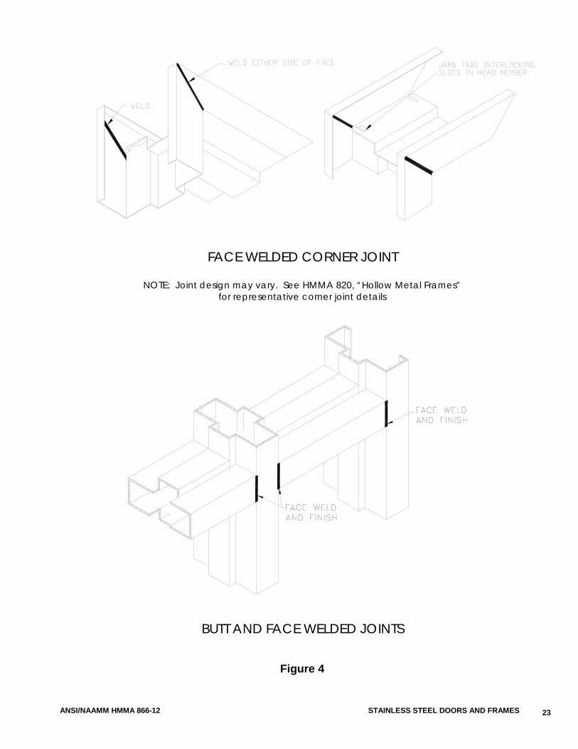
See Figure 4 and Appendix 4 for further details on frame welding.
i. [Continuously] [Face] weld perimeter flush or indented face joints. Finish flush face joints smooth with seamless faces.
ii. Weld members at internal indented intersections to concealed reinforcements, presenting hairline face seams.
iii. Provide hairline seams at all other intersection elements. d. Knocked-Down and Slip-On Frames
i. Ship components unassembled. ii. Factory prepare flush corner joints with steel reinforcing gussets not less than
0.032 in. (0.81 mm) thickness and/or integral tabs and slots which interlock upon assembly.
iii. Fabricate with corner joint design which assures component profile alignment and frame performance when field assembled by others under Section __ __ __ [_____], in accordance with the manufacturer’s installation instructions.
e. Furnish [welded] [knocked-down] [slip-on] frames at drywall partitions. Provide [welded] [knocked-down] frames at all other partition types. Slip-on frames are pressure fit type, installed after the partition is in place.
f. Prepare each door opening for single stud, resilient door silencers, three (3) per strike jamb for single door openings, two (2) per head for pairs, except on gasketed frame product. Silencers are supplied and installed by others under Section 08 71 00 [08700].]
[12. Moderately Corrosive Applications a. Fabricate profiles and all components from Type 304 stainless steel. b. Provide frames as [welded] [knock-down] [slip-on] units, transom frames, multi-
opening, sidelight and window assemblies as welded units. c. Welded Frame Product
See Figure 4 and Appendix 4 for further details on frame welding.
i. [Continuously] [Face] weld perimeter flush or indented face joints. Finish flush face joints smooth with seamless faces.
ii. Weld members at internal indented intersections to concealed reinforcements, presenting hairline face seams.
iii. Provide hairline seams at all other intersection elements.
11
STAINLESS STEEL DOORS AND FRAMES ANSI/NAAMM HMMA 866-12
d. Knocked-Down and Slip-On Frames i. Ship components unassembled. ii. Factory prepare flush corner joints with steel reinforcing gussets not less than
0.032 in. (0.81 mm) thickness and/or integral tabs and slots which interlock upon assembly.
iii. Fabricate with corner joint design which assures component profile alignment and frame performance when field assembled by others under Section __ __ __ [_____], in accordance with the manufacturer’s installation instructions.
e. Furnish [welded] [knocked-down] [slip-on] frames at drywall partitions. Provide [welded] [knocked-down] frames at all other partition types. Slip-on frames are pressure fit type, installed after the partition is in place.
f. Prepare each door opening for single stud, resilient door silencers, three (3) per strike jamb for single door openings, two (2) per head for pairs, except on gasketed frame product. Silencers are supplied and installed by others under Section 08 71 00 [08700].]
[13. Clean Room Applications Frame profile and component material Type should be specified based on the corrosion resistance required. For moderately corrosive applications Type 304 is recommended. When high corrosion resistance is necessary, specify Type 316 stainless steel.
a. Fabricate profiles and all components from Type [304] [316] stainless steel. b. Provide all frame product as welded units. c. Continuously weld, [internally] [or] [externally], perimeter joints from return to return.
Finish face joints at jambs, heads, mullions and sills smooth with seamless faces. For clean room applications the use of sidelight frames and other than 4-sided windows is not recommended.
Frame product for clean room applications are typically provided with a gasketing system provided under Section 08 71 00 [08720] - Weather Stripping and Gasketing, therefore preparations for door silencers are not required.]
[14. Aesthetic Applications a. Fabricate profiles from Type 304 stainless steel. b. Fabricate all other components for interior frame product from cold-rolled or hot-
rolled steel minimum. c. Fabricate all other components for exterior frame product from A60 (ZF180) or G60
(Z180) minimum Coating Designation zinc-coated steel. d. Provide frames as [welded] [knock-down] [slip-on] units, transom frames, multi-
opening, sidelight and window assemblies as welded units. e. Welded Frame Product
See Figure 4 and Appendix 4 for further details on frame welding.
i. [Continuously] [Face] weld perimeter flush or indented face joints. Finish flush face joints smooth with seamless faces.
ii. Weld members at internal indented intersections to concealed reinforcements, presenting hairline face seams.
iii. Provide hairline seams at all other intersection elements. f. Knocked-Down and Slip-On Frames
i. Ship components unassembled. ii. Factory prepare flush corner joints with steel reinforcing gussets not less than
0.032 in. (0.81 mm) thickness and/or integral tabs and slots which interlock upon assembly.
12
ANSI/NAAMM HMMA 866-12 STAINLESS STEEL DOORS AND FRAMES
iii. Fabricate with corner joint design which assures component profile alignment and frame performance when field assembled by others under Section __ __ __ [_____], in accordance with the manufacturer’s installation instructions.
g. Furnish welded, knocked-down or slip-on frames at drywall partitions. Provide welded or knocked-down frames at all other partition types. Slip-on frames are pressure fit type, installed after the partition is in place.]
15. Hardware Reinforcements and Preparations a. Mortise, reinforce, drill and tap frame product at the factory for templated hardware
only, in accordance with the approved hardware schedule and templates provided by the hardware supplier.
b. Reinforce frame product for surface mounted hardware, anchor hinges, thrust pivots, pivot reinforced hinges, continuous hinges or non-templated hardware. Drilling and tapping, by others in the field under Section __ __ __ [_____].
c. Weld all hardware reinforcements to frame product. d. Minimum steel thickness of hardware reinforcements:
i. Full mortise hinges and pivots ................ 0.167 in. x 1.25 in. x 10 in. length (4.24 mm x 31.7 mm x 254 mm) or 0.123 in. (3.12 mm) thickness angle or channel shaped type
ii. Strikes ...................................................... 0.093 in. (2.36 mm) or 0.053 in. (1.34 mm) unitized reinforcement with extruded tapped holes that provide equivalent number of threads as 0.093 in. (2.36 mm)
iii. Flush bolts, closers, hold-open arms and other surface applied hardware ........ 0.093 in. (2.36 mm)
16. Where electronic hardware is indicated on the Architect’s drawings or approved hardware schedule, provide prepared grout guards in accordance with the templates provided. Fabricate access plates, where required, of the same material, thickness and finish as the frame product, fastened with corrosion resistant screws. Secure access plates with a minimum of four (4) #8-32 machine screws or #6 sheet metal screws, spaced at 12 in. (305 mm) on center maximum.
17. Floor Anchors a. For welded and knocked-down frame product, weld floor anchors inside jambs.
Provide two (2) holes for fasteners supplied and installed by others under Section [06 10 00 [_____]] [09 20 00 [_____]].
b. Thickness of floor anchors; same as frame, minimum. c. Where specified or scheduled, provide welded adjustable floor anchors with not less
than 2 in. (50.8 mm) height adjustment. d. For applications that do not permit the use of a floor anchor, substitute an additional
jamb anchor at a location not to exceed 8 in. (204 mm) from the base of the jamb. 18. Jamb Anchors
a. Provide frame product with anchorage appropriate to frame and wall construction. b. Masonry Type
Provide steel adjustable jamb anchors of the strap and stirrup or T-strap type not less than 0.053 in. (1.34 mm) thickness or 0.156 in. (4 mm) diameter wire type, for frame product to be installed in new masonry walls. Straps; 2 in. x 10 in. (50 mm x 254 mm) in size minimum, corrugated and/or perforated. Place jamb anchors at a maximum of 18 in. (457 mm) from top and bottom of openings. Minimum number of anchors, spaced at maximum of 32 in. (813 mm) on center, provided on each jamb based on the over-all frame height:
13
STAINLESS STEEL DOORS AND FRAMES ANSI/NAAMM HMMA 866-12
i. Up to 60 in. (1524 mm) .............................. 2 anchors ii. Greater than 60 in. (1524 mm)
up to 90 in. (2286 mm) .............................. 3 anchors iii. Greater than 90 in. (2286 mm) up to 96 in. (2438 mm) .............................. 4 anchors iv. Greater than 96 in. (2438 mm) .................. 4 anchors plus one (1) for each 24
in. (610 mm) or fraction thereof, spaced at 24 in. (610 mm) maximum between anchors
c. Drywall Type Provide steel jamb anchors of suitable design, not less that 0.042 in. (1.06 mm) thickness, welded inside each jamb for frame product installed in drywall partitions. Place jamb anchors not greater than 18 in. (457 mm) from top and bottom of openings. Minimum number of anchors spaced at a maximum of 32 in. (813 mm) on center, provided on each jamb, based on the over-all frame height: i. Up to 60 in. (1524 mm) .............................. 3 anchors ii. Greater than 60 in. (1524 mm)
up to 90 in. (2286 mm) .............................. 4 anchors iii. Greater than 90 in. (2286 mm)
up to 96 in. (2438 mm) .............................. 5 anchors iv. Greater than 96 in. (2438 mm) .................. 5 anchors plus 1 for each 24 in.
(610 mm) or fraction thereof, spaced at 24 in. (610 mm) maximum between anchors
d. Compression Type Provide an adjustable compression anchor in each jamb and provision for secure attachment of each jamb base to stud runners for slip-on frames installed in stud partitions.
e. Expansion Bolt Type Prepare frame product for installation in existing masonry or concrete walls for expansion bolt type anchors. Provide a countersunk or dimpled hole for a 0.375 in. (9.5 mm) diameter flat head bolt and a spacer welded within the frame profile. Locate anchors a maximum of 6 in. (152 mm) from the top and bottom of the frame, with intermediate spacing at a maximum of 26 in. (660 mm) on center. Bolts and shields for such anchors provided and installed by others under Section 06 10 00 [_____].
f. Other Anchor Types Construct and provide frame product to be installed in pre-finished concrete, masonry or steel openings, with anchoring systems of suitable design as shown on the approved submittal drawings. Stainless steel fasteners for such anchors provided by others under Section 06 10 00 [_____]. A pre-finished opening may be one that is constructed as part of another assembly or system (e.g., pre-cast concrete panel) and which requires anchors similar in performance to those covered by 2.03.B.18.b and e.
19. Fabricate frame product installed in masonry walls with door openings greater than 48 in. (1219mm) in width with a steel channel or angle stiffener factory welded into the head, when the head is to be grouted. Provide stiffeners not less than 0.093 in. (2.36 mm) in thickness, not longer than the door opening width. Stiffeners and frame product are not be used as lintels or load bearing members.
20. Attach grout guards fabricated from not less than 0.016 in. (0.40 mm) thick steel at hardware mortises on frame product to be grouted.
21. For all door openings in welded frame product provide a temporary steel spreader welded or mechanically attached to the base of the jambs or mullions to serve as bracing during shipping and handling. Spreaders are not to be used for installation.
14
ANSI/NAAMM HMMA 866-12 STAINLESS STEEL DOORS AND FRAMES
22. In-Fill Panels a. Where specified or scheduled, provide in-fill panels for frame product. Secure panels
to frame sections with removable steel glazing stops and screws. b. For non-labeled frame product, construct in-fill panels from 0.032 in. (0.81 mm)
minimum thick stainless steel, of the same Type and Finish specified for the frame product, laminated to each face of the manufacturer’s standard solid backing.
c. For fire-rated frame product, construct in-fill panels from 0.032 in. (0.81 mm) minimum stainless steel, of the same Type and Finish specified for the frame product, laminated to each face of a solid fire-rated backing. Refer to NAAMM HMMA 850, “Fire-Rated Hollow Metal Doors and Frames”, for additional information.
23. Removable Glazing Stops a. Where specified, provide removable glass stops to secure glazing material or in-fill
panels to frame product located on the non-secure [or non-Clean Room] side of the frame, as designated on the Architect’s drawings and/or door schedules.
b. Fabricate removable glazing stops from stainless steel channel, not less than 0.032 in. (0.81 mm), of the same Type and Finish specified for the frame product, butted or mitered at corner joints and secured to the frame section using #6 minimum countersunk corrosion resistant sheet metal screws.
2.04 MANUFACTURING TOLERANCES
The manufacturer of the stainless steel doors and frame product is responsible only for the manufacturing tolerances listed in 2.04.A. The final clearances and relationships between door and frame depend on the setting of the frame and the hanging and adjustment of the door and hardware. See Section 3.02.
A. Maintain manufacturing tolerances within the following limits: 1. Frame Product for Singles or Pairs of Doors
a. Width measured between rabbets at the head: nominal opening width + 1/16 in. (1.5mm), - 1/32 in. (0.8mm)
b. Height (total length of jamb rabbet): nominal opening height + 1/16 in. (1.5 mm), - 1/32 in. (0.8 mm)
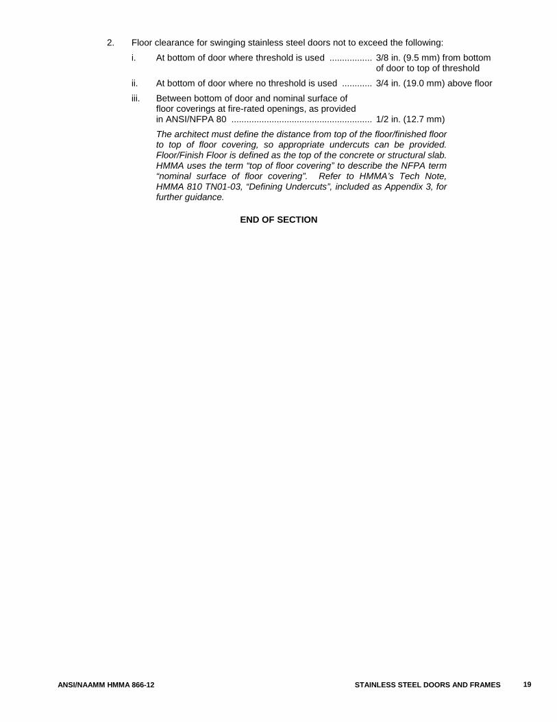
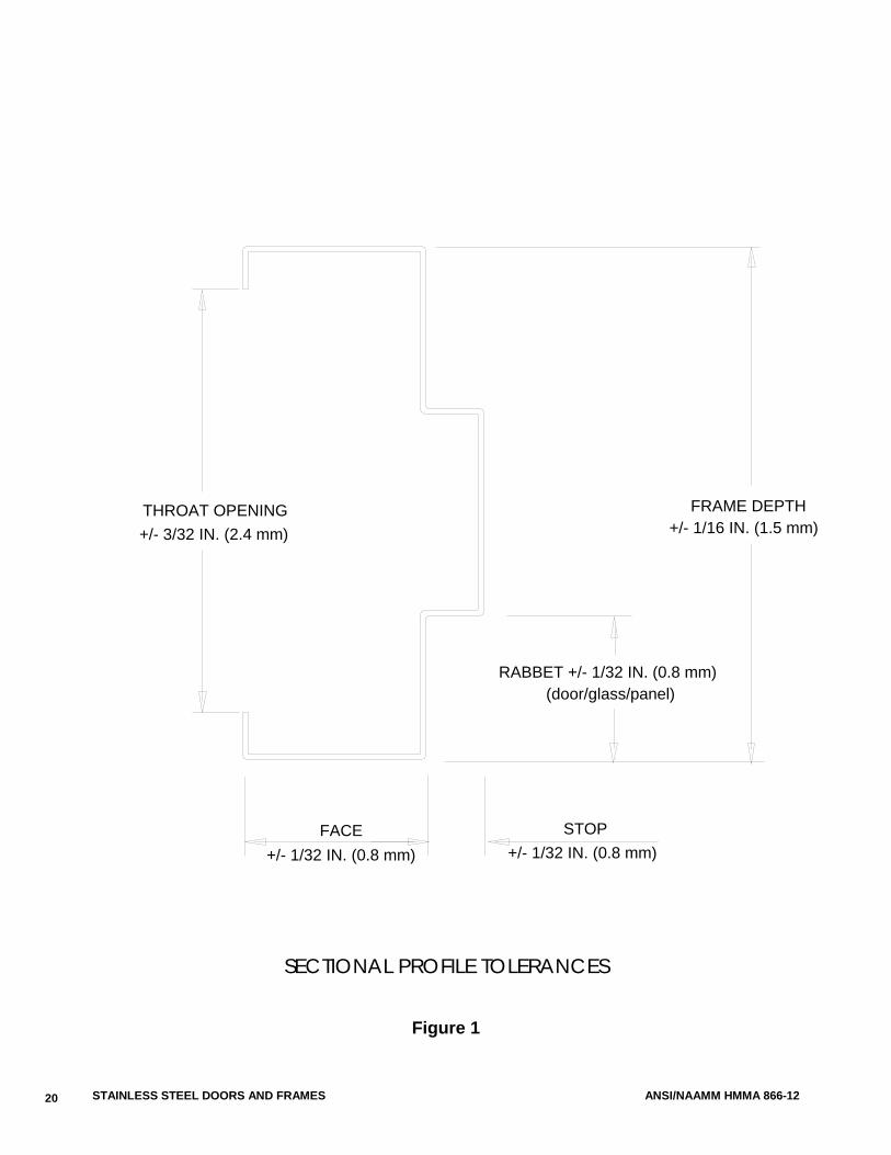
c. Cross sectional profile dimensions (see Figure 1): i. Face .................................. ± 1/32 in. (0.8 mm) ii. Stop .................................. ± 1/32 in. (0.8 mm) iii. Rabbet .............................. ± 1/32 in. (0.8 mm) iv. Depth ................................ ± 1/16 in. (1.5 mm) v. Throat ............................... ± 3/32 in. (2.3 mm) Frame product overlapping walls to have throat dimension 1/8 in. (3.1 mm) greater than dimensioned wall thickness to accommodate irregularities in wall construction.
2. Doors a. Width .......................................... ± 3/64 in. (1.2 mm) b. Height ......................................... ± 3/64 in. (1.2 mm) c. Thickness ................................... ± 1/16 in. (1.5 mm) d. Edge Flatness ........................... 1/16 in. (1.5 mm) maximum e. Surface Flatness ....................... 1/8 in. (3.1 mm) maximum
Stainless steel doors are undersized to fit the frame’s door opening. Edge clearances are based upon individual manufacturer’s designs.
15
STAINLESS STEEL DOORS AND FRAMES ANSI/NAAMM HMMA 866-12
3. Hardware a. Cutouts ....................................... Template dimensions + 0.015 in. (0.38 mm), - 0 b. Location ...................................... ± 1/32 in. (0.8 mm) c. Between hinge centerlines ........ ± 1/64 in. (0.4 mm)
2.05 HARDWARE LOCATIONS
A. Locate hardware on doors and frame product as listed below. All dimensions, except the hinge locations, are referenced from the floor as defined in Section 3.02.B.2.
When stainless steel frame products are specified for use with doors to be furnished by others, hardware preparation locations for the doors are normally governed by those in the frames, as stated in 2.05.A.
1. Hinges a. Top ............................................ 5 in. (127 mm) from underside of frame rabbet at
door opening to top of hinge b. Bottom ....................................... 10 in. (254 mm) from floor to bottom of hinge c. Intermediate .............................. Centered between top and bottom hinges d. On dutch doors .......................... 5 in. (127 mm) from underside of frame rabbet at
door opening to top of hinge; 10 in. (254 mm) from floor to bottom of bottom hinge; and 5 in. (127 mm) from split line to top and bottom of lower and upper intermediate hinges, respectively
2. Locks and latches ............................... 38 in. (965 mm) to centerline of knob or lever shaft 3. Deadlocks ........................................... 46 in. (1168 mm) to centerline of cylinder 4. Exit hardware ...................................... 38 in. (965 mm) to centerline of cross bar or as
shown on hardware template 5. Door pulls ............................................ 42 in. (1066 mm) to center of grip 6. Push/pull bars ..................................... 42 in. (1066 mm) to centerline of bar 7. Arm pulls ............................................. 46 in. (1168 mm) to centerline 8. Push plates ......................................... 46 in. (1168 mm) to centerline of plate 9. Roller latches ...................................... 45 in. (1143 mm) to centerline of latch
Note: See NAAMM/HMMA 830 and 831 for additional information.
2.06 FINISH
A. After fabrication, finish all tool marks and surface imperfections to make face sheets, vertical edges and weld joints free from irregularities.
B. Finish all exposed surfaces of doors and frame product to Number [2B] [4] [8] [other] finish, in accordance with Table 2 - Mechanical Finishes for Stainless Steel Sheet in Accordance with ASTM A 480/A 480M” contained in NAAMM’s HMMA 802, “Manufacturing of Hollow Metal Doors and Frames”.
Refer to Appendix 6 for the Table referenced above.
C. Provide vertical grained finishes at faces and edges of doors. D. Provide vertical grained finishes at jambs and vertical mullions and [horizontal] [vertical] grained
finishes at heads, horizontal mullions, center rails, sills and in-fill panels of frame product.
16
ANSI/NAAMM HMMA 866-12 STAINLESS STEEL DOORS AND FRAMES
PART 3 - EXECUTION
3.01 SITE STORAGE AND PROTECTION OF STAINLESS STEEL MATERIALS
Correct site storage and protection are essential to proper performance of doors and frame product. The requirements for proper storage are given in the following Section. However, it is important to recognize that these are not the responsibility of the stainless steel door or frame manufacturer. For this reason these requirements should be included in Sections 01 56 00 [_____] and 01 66 00 [_____] of the project specifications where they are generally specified. For additional information see NAAMM HMMA 840, “Guide Specification for Installation and Storage of Hollow Metal Doors and Frames”.
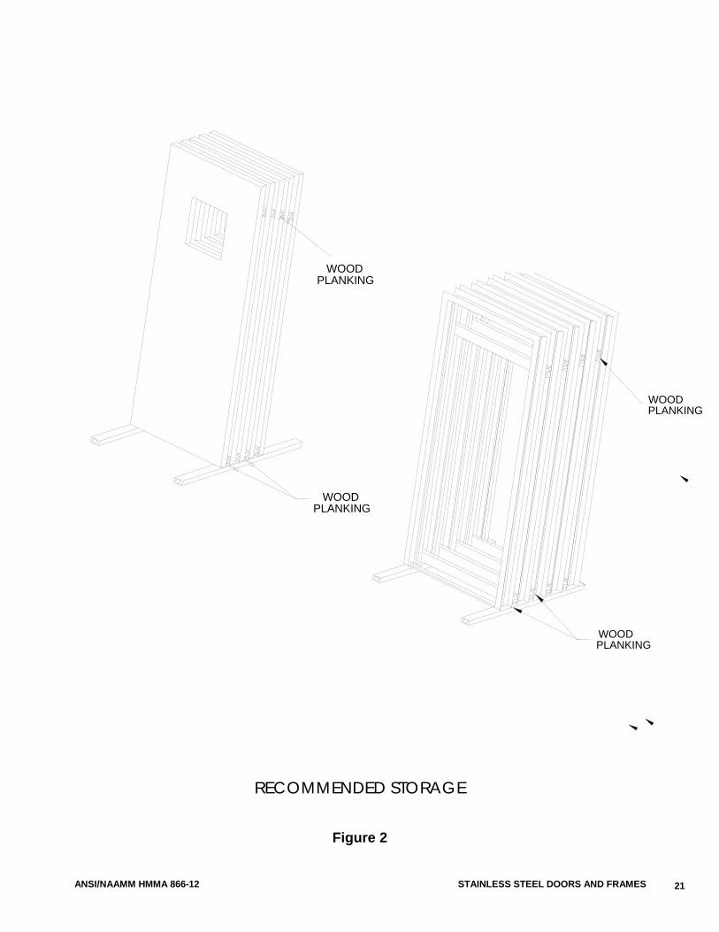
A. Do not remove wraps or covers from stainless steel doors and frame products until time of installation. The contractor responsible for receiving doors and frame product shall ensure that materials are unloaded, properly stored on planks or dunnage in a dry location and handled in a manner that will prevent damage.
B. Store door and frame product in a vertical position, spaced by blocking. Cover materials to protect them from damage and in such a manner as to permit air circulation.
Figure 2 illustrates recommended storage positioning.
3.02 INSTALLATION
Correct installation is essential to the proper performance of doors and frame product. The requirements for proper installation are given in the following Sections. Installation is not the responsibility of the stainless steel door or frame manufacturer. For this reason it should be included in Sections 06 10 00 [_____] and/or 09 20 00 [_____] of the project specifications where it is generally specified. For additional information see NAAMM HMMA 840, “Guide Specifications for Installation and Storage of Hollow Metal Doors and Frames”.
A. The Installer is responsible for the following: 1. Prior to installation, check the area of floor on which the frame product is to be installed and
within the path of the door swing, for flatness and correct as necessary. 2. Prior to installation, remove temporary spreaders. Check each door and frame product for
correct size, swing, fire rating and opening number. 3. Prior to installation, isolate and protect from grout and antifreeze agents, all interior
surfaces of perimeter frame product sections to be installed in masonry or concrete walls. The drawbacks and benefits associated with the use of water based masonry grouts, with or without antifreeze agents, should be carefully weighed during the detailing and specification process. Grouting of mullions and other closed sections is not recommended and plaster based grouts should not be used. Refer to NAAMM HMMA Tech Note, HMMA 820 TN01-03, “Grouting Hollow Metal Frames”, included as Appendix 2, for further guidance.
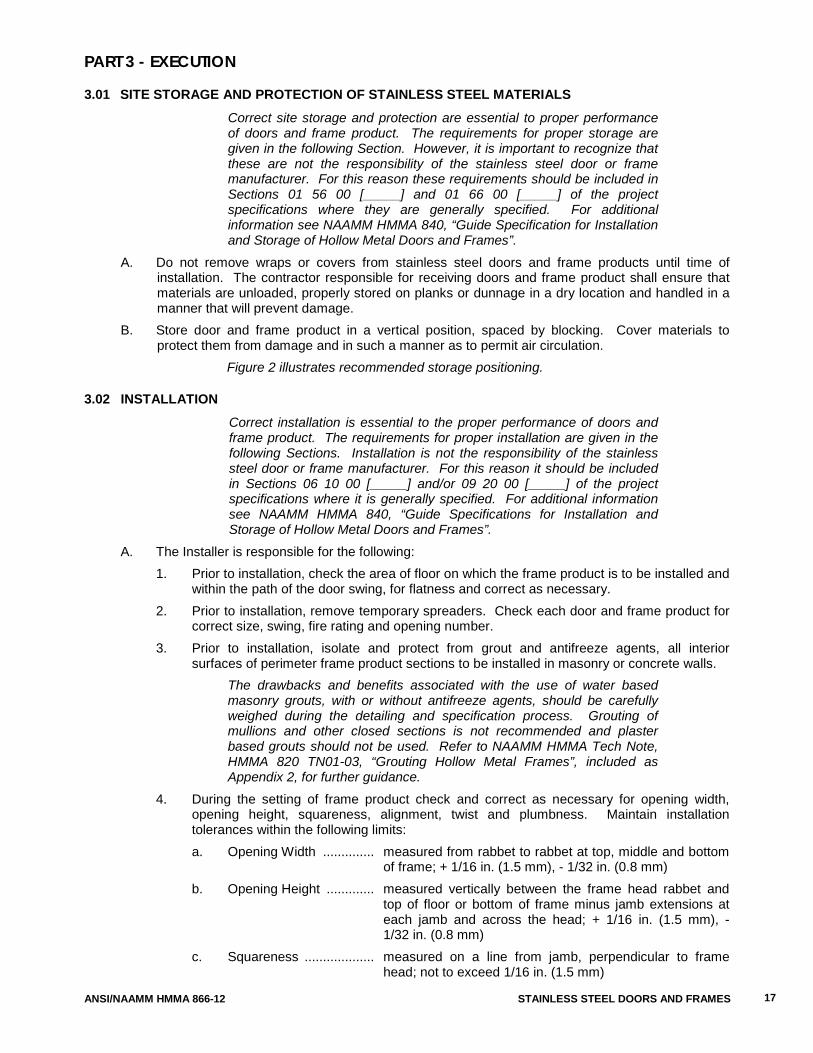
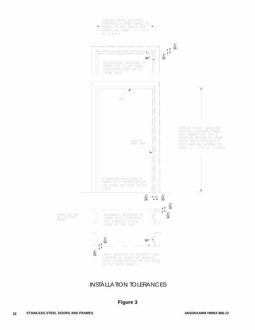
4. During the setting of frame product check and correct as necessary for opening width, opening height, squareness, alignment, twist and plumbness. Maintain installation tolerances within the following limits: a. Opening Width .............. measured from rabbet to rabbet at top, middle and bottom
of frame; + 1/16 in. (1.5 mm), - 1/32 in. (0.8 mm) b. Opening Height ............. measured vertically between the frame head rabbet and
top of floor or bottom of frame minus jamb extensions at each jamb and across the head; + 1/16 in. (1.5 mm), - 1/32 in. (0.8 mm)
c. Squareness ................... measured on a line from jamb, perpendicular to frame head; not to exceed 1/16 in. (1.5 mm)
17
STAINLESS STEEL DOORS AND FRAMES ANSI/NAAMM HMMA 866-12
d. Alignment ...................... measured at jambs on a horizontal line parallel to the plane of the face; not to exceed 1/16 in. (1.5 mm)
e. Twist .............................. measured at opposite face corners of jambs on parallel lines perpendicular to the plane of the door rabbet; not to exceed 1/16 in. (1.5 mm)
f. Plumbness ..................... measured at the jambs on a perpendicular line from the head to the floor; not to exceed 1/16 in. (1.5 mm)
The above tolerances provide a reasonable guideline for proper installation of stainless steel frame product. However, it should be noted that the cumulative affect of the installation tolerances at or near their maximum levels could result in sufficient misalignment to prevent the door from functioning properly. Installers should be careful not to create a tolerance buildup. Tolerance buildup occurs when several tolerances are at or near their maximums.
The details in Figure 3 illustrate methods of measuring the above specified tolerances.
5. Grout guards are intended to protect hardware mortises and tapped holes from masonry grout of 4 in. (101 mm) maximum slump consistency which is hand troweled in place. If a lighter consistency grout (greater than 4 in. (101 mm) slump when tested in accordance with ASTM C 143/C 143M) is to be used, special precautions must be taken in the field by the installer to protect the aforementioned.
6. Frame products are not intended or designed to act as forms for grout or concrete. Grout frame sections in “lifts” or take precautions to ensure that frames are not deformed or damaged by the hydraulic forces that occur during this process.
7. Keep stainless steel surfaces free of grout, tar and/or other bonding materials or sealers. Promptly clean grout, tar, bonding materials or sealers off doors and frame product.
8. Installer to refinish to match original, any marks caused by spreader removal. 9. Promptly finish smooth and refinish to match the original, any finished or polished surfaces which
have been scratched or otherwise marred during installation, cleaning and/or field welding. 10. Install labeled fire doors and frame product in accordance with the terms of their listings,
ANSI/NFPA 80 or the local Authority Having Jurisdiction. 11. Install hardware in accordance with hardware manufacturer’s templates and instructions. 12. Maintain proper door clearances in accordance with Section 3.02.B, except for special
conditions otherwise noted. Where necessary, metal hinge shims, furnished by installer, are permitted to maintain clearances.
13. Install door silencers. 14. Install glazing materials in accordance with Section 08 80 00 [08800].
For Clean Room applications it is recommended that hardware and glazing materials are sealed. Depending upon the level of cleanliness required, additional considerations may be necessary during hardware and glazing installation.
B. Clearances
1. Provide a minimum of 1/32 in. (0.8 mm) edge clearance for swinging stainless steel doors in order to provide for the functional operation of the assembly. Edge clearances not to exceed the following: i. Between doors and frame product at head and jambs .................................................................... 3/16 in. (4.7 mm) ii. Between edges of pairs of doors ................................ 3/16 in. (4.7 mm)
Edge clearance for labeled fire doors and frame products is covered by 3.02.A.10.
18
ANSI/NAAMM HMMA 866-12 STAINLESS STEEL DOORS AND FRAMES
2. Floor clearance for swinging stainless steel doors not to exceed the following: i. At bottom of door where threshold is used ................. 3/8 in. (9.5 mm) from bottom of door to top of threshold ii. At bottom of door where no threshold is used ............ 3/4 in. (19.0 mm) above floor iii. Between bottom of door and nominal surface of floor coverings at fire-rated openings, as provided in ANSI/NFPA 80 ........................................................ 1/2 in. (12.7 mm)
The architect must define the distance from top of the floor/finished floor to top of floor covering, so appropriate undercuts can be provided. Floor/Finish Floor is defined as the top of the concrete or structural slab. HMMA uses the term “top of floor covering” to describe the NFPA term “nominal surface of floor covering”. Refer to HMMA’s Tech Note, HMMA 810 TN01-03, “Defining Undercuts”, included as Appendix 3, for further guidance.
END OF SECTION
19
STAINLESS STEEL DOORS AND FRAMES ANSI/NAAMM HMMA 866-12
SECTIONAL PROFILE TOLERANCES
Figure 1
20
+/- 1/32 IN. (0.8 mm)STOP
+/- 1/32 IN. (0.8 mm)FACE
(door/glass/panel)RABBET +/- 1/32 IN. (0.8 mm)
+/- 3/32 IN. (2.4 mm)THROAT OPENING
+/- 1/16 IN. (1.5 mm)FRAME DEPTH
ANSI/NAAMM HMMA 866-12 STAINLESS STEEL DOORS AND FRAMES
RECOMMENDED STORAGE
Figure 2
21
PLANKINGWOOD
PLANKINGWOOD
PLANKINGWOOD
PLANKINGWOOD
STAINLESS STEEL DOORS AND FRAMES ANSI/NAAMM HMMA 866-12
INSTALLATION TOLERANCES
Figure 3
22
90°
90°
1"16
161"
1"1616
1"
161"
1"16
1"16
1"16
ANSI/NAAMM HMMA 866-12 STAINLESS STEEL DOORS AND FRAMES
FACE WELDED CORNER JOINT
NOTE: Joint design may vary. See HMMA 820, “Hollow Metal Frames” for representative corner joint details
BUTT AND FACE WELDED JOINTS
Figure 4
23
STAINLESS STEEL DOORS AND FRAMES ANSI/NAAMM HMMA 866-12
APPENDIX 1 (Not part of the Standard)
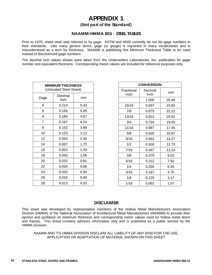
NAAMM/HMMA 803 - STEEL TABLES
Prior to 1970, sheet steel was referred to by gage. ASTM and ANSI currently do not list gage numbers in their standards. Like many generic terms, gage (or gauge) is ingrained in many vocabularies and is misunderstood as a term for thickness. NAAMM is publishing this Minimum Thickness Table to be used instead of discontinued gage numbers.
The decimal inch values shown were taken from the Underwriters Laboratories, Inc. publication for gage number and equivalent thickness. Corresponding metric values are included for reference purposes only.
MINIMUM THICKNESS (Uncoated Steel Sheet)
Gage Decimal Inch mm
4 0.214 5.43 5 0.199 5.05 6 0.184 4.67 7 0.167 4.24 8 0.152 3.86 10 0.123 3.12 12 0.093 2.36 14 0.067 1.70 16 0.053 1.34 18 0.042 1.06 20 0.032 0.81 22 0.026 0.66 24 0.020 0.50 26 0.016 0.40 28 0.013 0.33
CONVERSION Fractional
Inch Decimal
Inch mm
1.000 25.40 15/16 0.937 23.80
7/8 0.875 22.22 13/16 0.812 20.62
3/4 0.750 19.05 11/16 0.687 17.45
5/8 0.625 15.87 9/16 0.562 14.27 1/2 0.500 12.70 7/16 0.437 11.10 3/8 0.375 9.52 5/16 0.312 7.92 1/4 0.250 6.35 3/16 0.187 4.75 1/8 0.125 3.17 1/16 0.062 1.57
DISCLAIMER
This sheet was developed by representative members of the Hollow Metal Manufacturers Association Division (HMMA) of the National Association of Architectural Metal Manufacturers (NAAMM) to provide their opinion and guidance on minimum thickness and corresponding metric values used for hollow metal doors and frames. This sheet contains advisory information only and is published as a public service by the HMMA Division.
NAAMM AND ITS HMMA DIVISION DISCLAIM ALL LIABILITY OF ANY KIND FOR THE USE, APPLICATION OR ADAPTATION OF MATERIAL SHOWN ON THIS SHEET
A1
ANSI/NAAMM HMMA 866-12 STAINLESS STEEL DOORS AND FRAMES
APPENDIX 2 (Not part of the Standard)
GROUTING HOLLOW METAL FRAMES
HMMA-820 TN01
Grout, when used in accordance with industry guidelines, can improve frame durability, sound deadening and, depending on wall construction, increases frame anchorage strength. Grouting of the frame does not increase door durability, nor is it required for fire-rated frames. For most commercial applications, grouting of mullions and other closed sections is not recommended. For applications covered by ANSI/NAAMM HMMA 862, "Guide Specifications for Commercial Security Hollow Metal Doors and Frames", and ANSI/NAAMM HMMA 863, "Guide Specifications for Detention Security Hollow Metal Doors and Frames", the standards require that "frame jambs shall be fully grouted to provide added security protection against battering, wedging, spreading, and other means of forcing open the door". Grout is a water-based product. If not used properly, it can destroy the opening in a very short time. Grout can be either “mortar”, which is a masonry mixture of lime, cement, sand and water, or “plaster”, a gypsum-based product. Plaster grout dries with exposure to air. When a frame member is filled solid with plaster grout, only those areas exposed to air will dry and harden, while the center remains wet (uncured). The water remaining in the plaster grout can rust the frame from the inside. Mortar grout cures by chemical reaction and hardens throughout. Use mortar grout. Frames are not designed to act as forms for grout. Grout must have a maximum 4 in. slump and be hand troweled in place. Bracing of the frame may be necessary prior to grouting to prevent sagging of the header or bowing of the jamb due to weight or pressure of the grout. Grout should not be installed after gypsum wallboard is installed, as the liquid within the grout will deteriorate the wallboard. When dictated by temperatures, anti-freezing agents for mortar may be recommended by specifications. These agents can adversely affect metal and all surfaces in contact with grout must be coated with a corrosion resistant material. It is recommended that the contractor be responsible for the grouting and for any additional barrier coating. It is also the contractor's responsibility to use care in the application of the grout.
A2
STAINLESS STEEL DOORS AND FRAMES ANSI/NAAMM HMMA 866-12
APPENDIX 3 (Not part of the Standard)
DEFINING UNDERCUTS
HMMA-810 TN01
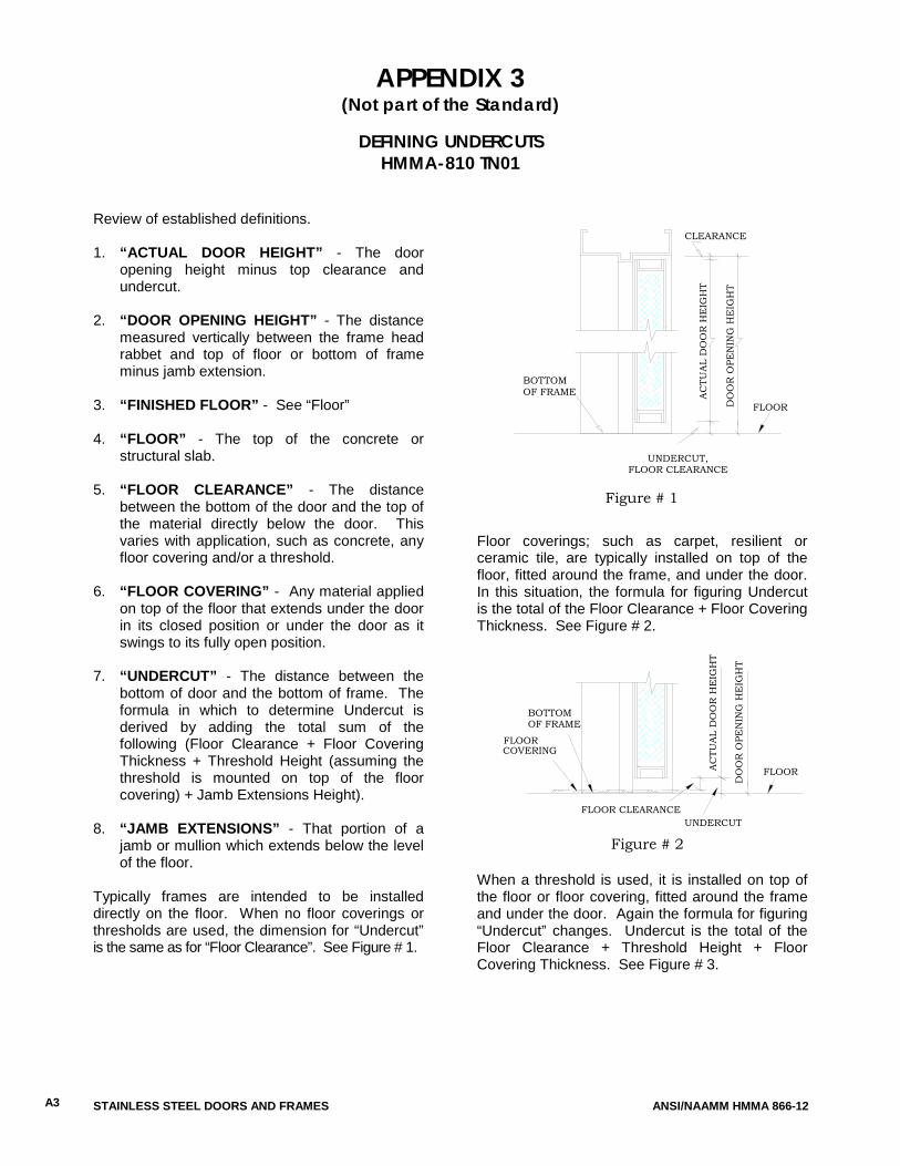
Review of established definitions. 1. “ACTUAL DOOR HEIGHT” - The door
opening height minus top clearance and undercut.
2. “DOOR OPENING HEIGHT” - The distance
measured vertically between the frame head rabbet and top of floor or bottom of frame minus jamb extension.
3. “FINISHED FLOOR” - See “Floor” 4. “FLOOR” - The top of the concrete or
structural slab.
5. “FLOOR CLEARANCE” - The distance between the bottom of the door and the top of the material directly below the door. This varies with application, such as concrete, any floor covering and/or a threshold.
6. “FLOOR COVERING” - Any material applied
on top of the floor that extends under the door in its closed position or under the door as it swings to its fully open position.
7. “UNDERCUT” - The distance between the
bottom of door and the bottom of frame. The formula in which to determine Undercut is derived by adding the total sum of the following (Floor Clearance + Floor Covering Thickness + Threshold Height (assuming the threshold is mounted on top of the floor covering) + Jamb Extensions Height).
8. “JAMB EXTENSIONS” - That portion of a
jamb or mullion which extends below the level of the floor.
Typically frames are intended to be installed directly on the floor. When no floor coverings or thresholds are used, the dimension for “Undercut” is the same as for “Floor Clearance”. See Figure # 1.
Floor coverings; such as carpet, resilient or ceramic tile, are typically installed on top of the floor, fitted around the frame, and under the door. In this situation, the formula for figuring Undercut is the total of the Floor Clearance + Floor Covering Thickness. See Figure # 2. When a threshold is used, it is installed on top of the floor or floor covering, fitted around the frame and under the door. Again the formula for figuring “Undercut” changes. Undercut is the total of the Floor Clearance + Threshold Height + Floor Covering Thickness. See Figure # 3.
FLOOR
FLOOR CLEARANCE
Figure # 2
AC
TUA
L D
OO
R H
EIG
HT
DO
OR
OPE
NIN
G H
EIG
HT
BOTTOMOF FRAME
UNDERCUT
FLOORCOVERING
AC
TUA
L D
OO
R H
EIG
HT
BOTTOMOF FRAME
DO
OR
OPE
NIN
G H
EIG
HT
Figure # 1
CLEARANCE
FLOOR
UNDERCUT,FLOOR CLEARANCE
A3
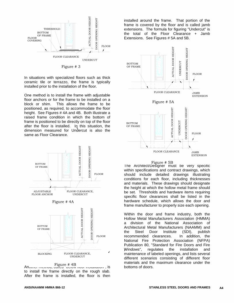
ANSI/NAAMM HMMA 866-12 STAINLESS STEEL DOORS AND FRAMES
In situations with specialized floors such as thick ceramic tile or terrazzo, the frame is typically installed prior to the installation of the floor. One method is to install the frame with adjustable floor anchors or for the frame to be installed on a block or shim. This allows the frame to be positioned, as required, to accommodate the floor height. See Figures # 4A and 4B. Both illustrate a raised frame condition in which the bottom of frame is positioned to be directly on top of the floor after the floor is installed. In this situation, the dimension measured for Undercut is also the same as Floor Clearance.
Another method, called "below floor installation", is to install the frame directly on the rough slab. After the frame is installed, the floor is then
installed around the frame. That portion of the frame is covered by the floor and is called jamb extensions. The formula for figuring "Undercut" is the total of the Floor Clearance + Jamb Extensions. See Figures # 5A and 5B. The Architect/Designer must be very specific within specifications and contract drawings, which should include detailed drawings illustrating conditions for each floor, including thicknesses and materials. These drawings should designate the height at which the hollow metal frame should be set. Thresholds and hardware items requiring specific floor clearances shall be listed in the hardware schedule, which allows the door and frame manufacturer to properly size each opening. Within the door and frame industry, both the Hollow Metal Manufacturers Association (HMMA) a division of the National Association of Architectural Metal Manufacturers (NAAMM) and the Steel Door Institute (SDI), publish recommended clearances. In addition, the National Fire Protection Association (NFPA) Publication 80, "Standard for Fire Doors and Fire Windows", regulates the installation and maintenance of labeled openings, and lists several different scenarios consisting of different floor materials and the maximum clearance under the bottoms of doors.
BOTTOMOF FRAME
FLOOR
DO
OR
OPE
NIN
G H
EIG
HT
Figure # 4A
AC
TUA
L D
OO
R H
EIG
HT
FLOOR CLEARANCE,UNDERCUT
ADJUSTABLE FLOOR ANCHOR
Figure # 4B
BOTTOMOF FRAME
DO
OR
OPE
NIN
G H
EIG
HT
AC
TUA
L D
OO
R H
EIG
HT
FLOOR CLEARANCE,UNDERCUT
FLOOR
BLOCKING
AC
TUA
L D
OO
R H
EIG
HT
FLOOR CLEARANCE
FLOOR
Figure # 5A
UN
DE
RC
UT
DO
OR
OPE
NIN
G H
EIG
HT
BOTTOMOF FRAME
JAMBEXTENSION
DO
OR
OPE
NIN
G H
EIG
HT
AC
TUA
L D
OO
R H
EIG
HT
FLOOR CLEARANCE
BOTTOMOF FRAME
Figure # 5B
EXTENSIONJAMB
UN
DE
RC
UT
FLOOR
FLOORCOVERING
Figure # 3
THRESHOLD
AC
TUA
L D
OO
R H
EIG
HT
DO
OR
OPE
NIN
G H
EIG
HT
FLOOR CLEARANCEUNDERCUT
BOTTOMOF FRAME
FLOOR
A4
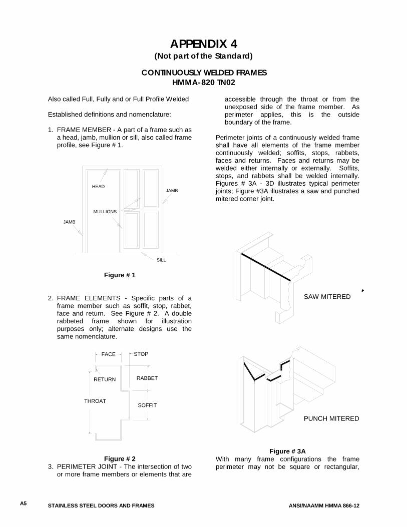
STAINLESS STEEL DOORS AND FRAMES ANSI/NAAMM HMMA 866-12
APPENDIX 4 (Not part of the Standard)
CONTINUOUSLY WELDED FRAMES
HMMA-820 TN02 Also called Full, Fully and or Full Profile Welded Established definitions and nomenclature: 1. FRAME MEMBER - A part of a frame such as
a head, jamb, mullion or sill, also called frame profile, see Figure # 1.
Figure # 1 2. FRAME ELEMENTS - Specific parts of a
frame member such as soffit, stop, rabbet, face and return. See Figure # 2. A double rabbeted frame shown for illustration purposes only; alternate designs use the same nomenclature.
Figure # 2 3. PERIMETER JOINT - The intersection of two
or more frame members or elements that are
accessible through the throat or from the unexposed side of the frame member. As perimeter applies, this is the outside boundary of the frame.
Perimeter joints of a continuously welded frame shall have all elements of the frame member continuously welded; soffits, stops, rabbets, faces and returns. Faces and returns may be welded either internally or externally. Soffits, stops, and rabbets shall be welded internally. Figures # 3A - 3D illustrates typical perimeter joints; Figure #3A illustrates a saw and punched mitered corner joint.
Figure # 3A With many frame configurations the frame perimeter may not be square or rectangular,
A5
JAMB
MULLIONS
HEAD
SILL
JAMB
FACE
RETURN
THROATSOFFIT
RABBET
STOP
SAW MITERED
PUNCH MITERED
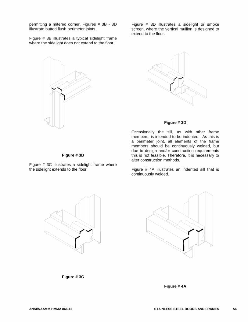
ANSI/NAAMM HMMA 866-12 STAINLESS STEEL DOORS AND FRAMES
permitting a mitered corner. Figures # 3B - 3D illustrate butted flush perimeter joints. Figure # 3B illustrates a typical sidelight frame where the sidelight does not extend to the floor.
Figure # 3B Figure # 3C illustrates a sidelight frame where the sidelight extends to the floor.
Figure # 3C
Figure # 3D illustrates a sidelight or smoke screen, where the vertical mullion is designed to extend to the floor.
Figure # 3D Occasionally the sill, as with other frame members, is intended to be indented. As this is a perimeter joint, all elements of the frame members should be continuously welded, but due to design and/or construction requirements this is not feasible. Therefore, it is necessary to alter construction methods. Figure # 4A illustrates an indented sill that is continuously welded.
Figure # 4A
A6
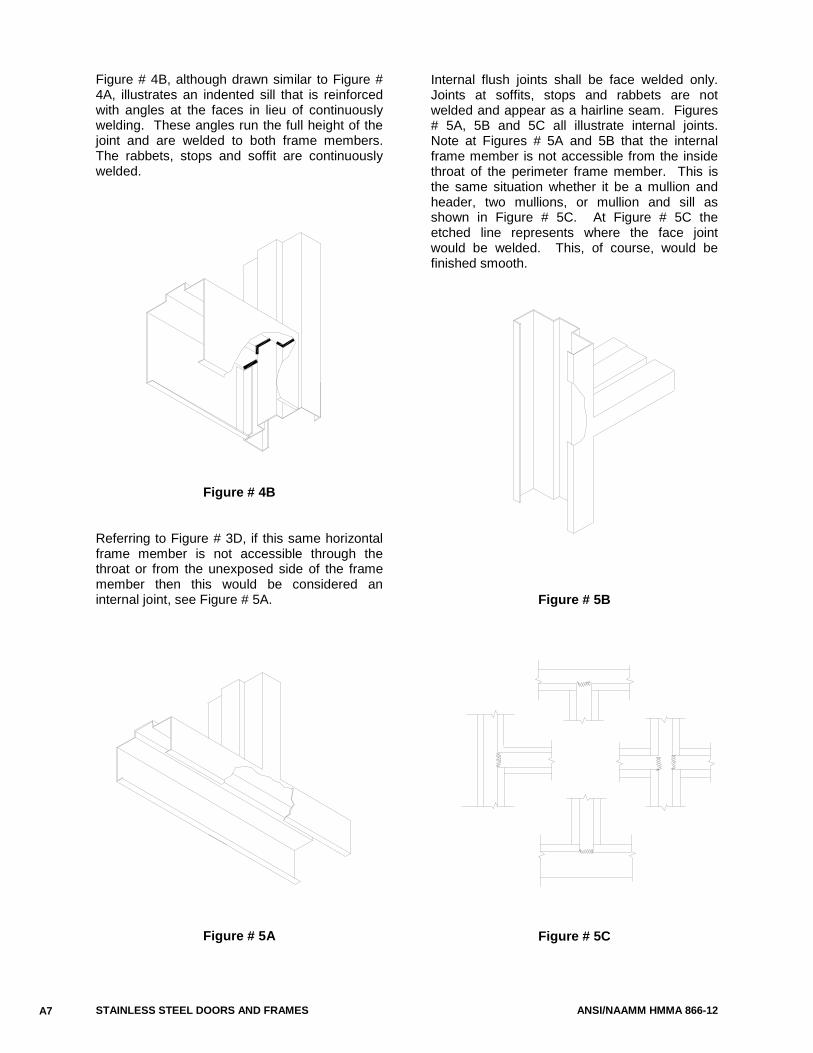
STAINLESS STEEL DOORS AND FRAMES ANSI/NAAMM HMMA 866-12
Figure # 4B, although drawn similar to Figure # 4A, illustrates an indented sill that is reinforced with angles at the faces in lieu of continuously welding. These angles run the full height of the joint and are welded to both frame members. The rabbets, stops and soffit are continuously welded.
Figure # 4B Referring to Figure # 3D, if this same horizontal frame member is not accessible through the throat or from the unexposed side of the frame member then this would be considered an internal joint, see Figure # 5A.
Figure # 5A
Internal flush joints shall be face welded only. Joints at soffits, stops and rabbets are not welded and appear as a hairline seam. Figures # 5A, 5B and 5C all illustrate internal joints. Note at Figures # 5A and 5B that the internal frame member is not accessible from the inside throat of the perimeter frame member. This is the same situation whether it be a mullion and header, two mullions, or mullion and sill as shown in Figure # 5C. At Figure # 5C the etched line represents where the face joint would be welded. This, of course, would be finished smooth.
Figure # 5B
Figure # 5C
A7
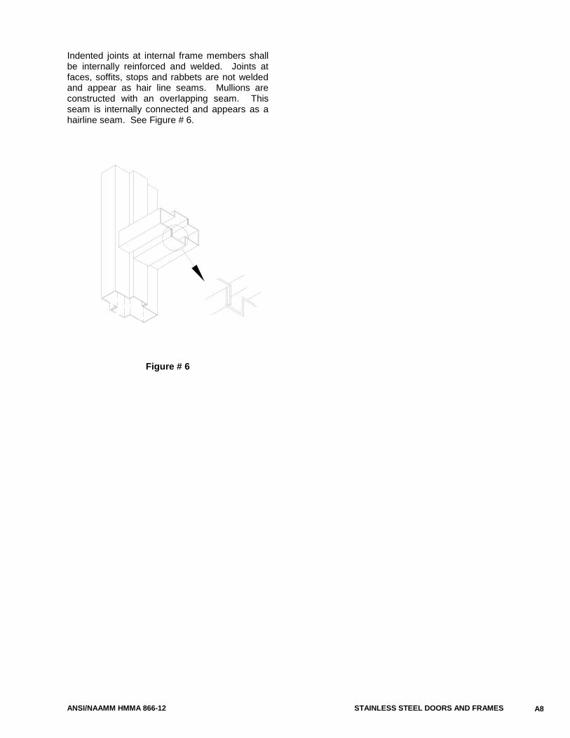
ANSI/NAAMM HMMA 866-12 STAINLESS STEEL DOORS AND FRAMES
Indented joints at internal frame members shall be internally reinforced and welded. Joints at faces, soffits, stops and rabbets are not welded and appear as hair line seams. Mullions are constructed with an overlapping seam. This seam is internally connected and appears as a hairline seam. See Figure # 6.
Figure # 6
A8
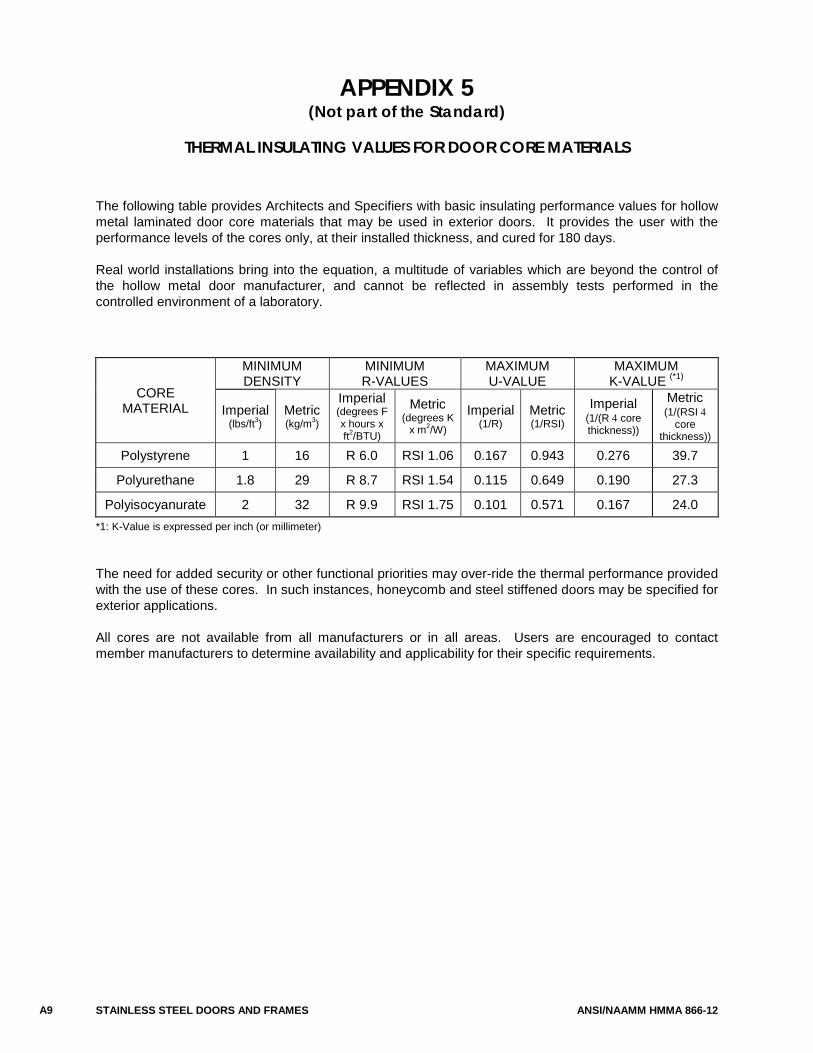
STAINLESS STEEL DOORS AND FRAMES ANSI/NAAMM HMMA 866-12
APPENDIX 5 (Not part of the Standard)
THERMAL INSULATING VALUES FOR DOOR CORE MATERIALS
The following table provides Architects and Specifiers with basic insulating performance values for hollow metal laminated door core materials that may be used in exterior doors. It provides the user with the performance levels of the cores only, at their installed thickness, and cured for 180 days.
Real world installations bring into the equation, a multitude of variables which are beyond the control of the hollow metal door manufacturer, and cannot be reflected in assembly tests performed in the controlled environment of a laboratory.
CORE MATERIAL
MINIMUM DENSITY
MINIMUM R-VALUES
MAXIMUM U-VALUE
MAXIMUM K-VALUE (*1)
Imperial (lbs/ft3
Metric ) (kg/m3
Imperial
) (degrees F x hours x ft2
Metric
/BTU)
(degrees K x m2
Imperial /W) (1/R)
Metric (1/RSI)
Imperial (1/(R 4 core thickness))
Metric (1/(RSI 4
core thickness))
Polystyrene 1 16 R 6.0 RSI 1.06 0.167 0.943 0.276 39.7
Polyurethane 1.8 29 R 8.7 RSI 1.54 0.115 0.649 0.190 27.3
Polyisocyanurate 2 32 R 9.9 RSI 1.75 0.101 0.571 0.167 24.0 *1: K-Value is expressed per inch (or millimeter) The need for added security or other functional priorities may over-ride the thermal performance provided with the use of these cores. In such instances, honeycomb and steel stiffened doors may be specified for exterior applications.
All cores are not available from all manufacturers or in all areas. Users are encouraged to contact member manufacturers to determine availability and applicability for their specific requirements.
A9
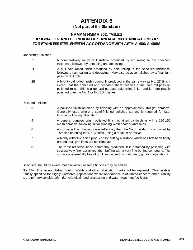
ANSI/NAAMM HMMA 866-12 STAINLESS STEEL DOORS AND FRAMES
APPENDIX 6 (Not part of the Standard)
NAAMM HMMA 802, TABLE 2
DESIGNATION AND DEFINITION OF STANDARD MECHANICAL FINISHES FOR STAINLESS STEEL SHEET IN ACCORDANCE WITH ASTM A 480/A 480M
Unpolished Finishes
1 A comparatively rough dull surface produced by hot rolling to the specified thickness, followed by annealing and descaling.
2D A dull cold rolled finish produced by cold rolling to the specified thickness, followed by annealing and descaling. May also be accomplished by a final light pass on dull rolls.
2B A bright cold rolled finish commonly produced in the same way as No. 2D finish, except that the annealed and descaled sheet receives a final cold roll pass on polished rolls. This is a general purpose cold rolled finish and is more readily polished than the No. 1 or No. 2D finishes.
Polished Finishes
3 A polished finish obtained by finishing with an approximately 100 grit abrasive. Generally used where a semi-finished polished surface is required for later finishing following fabrication.
4 A general purpose bright polished finish obtained by finishing with a 120-150 mesh abrasive, following initial grinding width coarser abrasives.
6 A soft satin finish having lower reflectivity than the No. 4 finish. It is produced by Tampico brushing the No. 4 finish, using a medium abrasive.
7 A highly reflective finish produced by buffing a surface which has first been finely ground, but “grit” lines are not removed.
8 The most reflective finish commonly produced. It is obtained by polishing with successively finer abrasives, then buffing with a very fine buffing compound. The surface is essentially free of grit lines caused by preliminary grinding operations.
Specifiers should be aware that availability of some finishes may be limited. No. 2B-mill is an unpolished finish. Welds and other fabrication marks will be exposed. This finish is usually specified for Highly Corrosive Applications where appearance is of limited concern and durability is the primary consideration (i.e. chemical, food processing and water treatment facilities).
A10
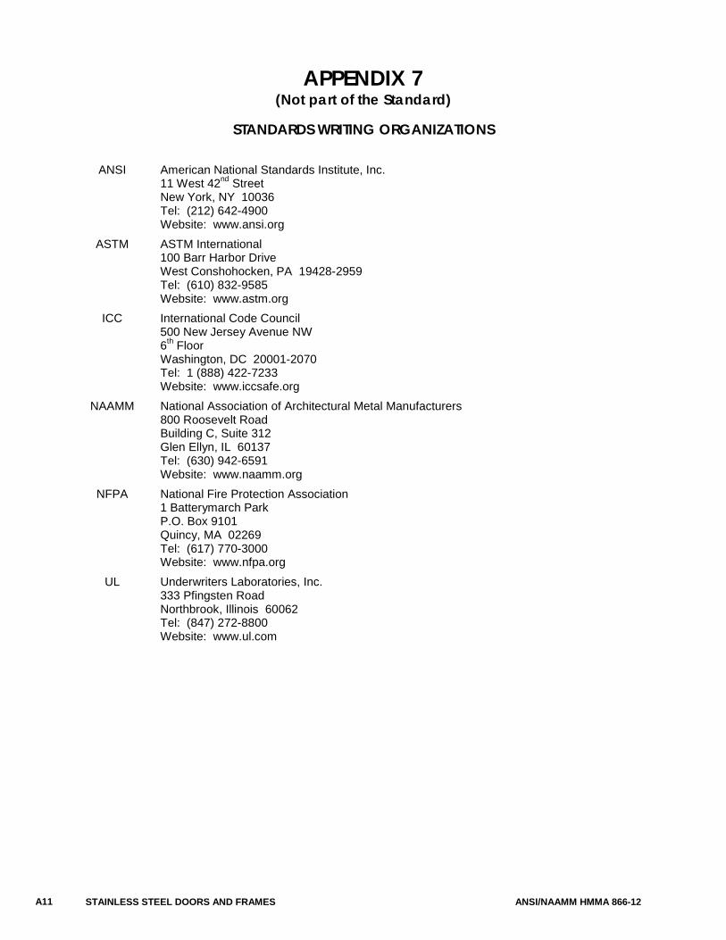
STAINLESS STEEL DOORS AND FRAMES ANSI/NAAMM HMMA 866-12
APPENDIX 7 (Not part of the Standard)
STANDARDS WRITING ORGANIZATIONS
ANSI American National Standards Institute, Inc. 11 West 42nd
New York, NY 10036 Street
Tel: (212) 642-4900 Website: www.ansi.org ASTM ASTM International 100 Barr Harbor Drive West Conshohocken, PA 19428-2959 Tel: (610) 832-9585 Website: www.astm.org ICC International Code Council 500 New Jersey Avenue NW 6th
Washington, DC 20001-2070 Floor
Tel: 1 (888) 422-7233 Website: www.iccsafe.org NAAMM National Association of Architectural Metal Manufacturers 800 Roosevelt Road Building C, Suite 312 Glen Ellyn, IL 60137 Tel: (630) 942-6591 Website: www.naamm.org NFPA National Fire Protection Association 1 Batterymarch Park P.O. Box 9101 Quincy, MA 02269 Tel: (617) 770-3000 Website: www.nfpa.org UL Underwriters Laboratories, Inc. 333 Pfingsten Road Northbrook, Illinois 60062 Tel: (847) 272-8800 Website: www.ul.com
A11

ANSI/NAAMM HMMA 866-12 STAINLESS STEEL DOORS AND FRAMES
STAINLESS STEEL DOORS AND FRAMES ANSI/NAAMM HMMA 866-12
RECOMMENDED GUIDE SPECIFICATIONS FOR HMMA HOLLOW METAL DOORS AND FRAMES HMMA 860 - Hollow Metal Doors and Frames ANSI/NAAMM HMMA 861 - Commercial Hollow Metal Doors and Frames ANSI/NAAMM HMMA 862 - Commercial Security Hollow Metal Doors and Frames ANSI/NAAMM HMMA 863 - Detention Security Hollow Metal Doors and Frames ANSI/NAAMM HMMA 865 - Swinging Sound Control Hollow Metal Doors and Frames ANSI/NAAMM HMMA 866 - Stainless Steel Hollow Metal Doors and Frames ANSI/NAAMM HMMA 867 - Commercial Laminated Core Hollow Metal Doors and Frames RELATED HMMA DOCUMENTS HMMA 800 - Introduction to Hollow Metal HMMA 801 - Glossary of Terms for Hollow Metal Doors and Frames HMMA 802 - Manufacturing of Hollow Metal Doors and Frames HMMA 803 - Steel Tables HMMA 810 - Hollow Metal Doors HMMA 820 - Hollow Metal Frames HMMA 830 - Hardware Selection for Hollow Metal Doors and Frames HMMA 831 - Recommended Hardware Locations for Hollow Metal Doors and Frames HMMA 840 - Installation and Storage of Hollow Metal Doors and Frames HMMA 841 - Tolerances and Clearances for Commercial Hollow Metal Doors and Frames HMMA 850 - Fire-Rated Hollow Metal Doors and Frames HMMA 890 - Technical Summary HMMA 810-TN01 - Defining Undercuts HMMA 820-TN01 - Grouting Hollow Metal Frames HMMA 820-TN02 - Continuously Welded Frames HMMA 820-TN03 - Guidelines for Glazing Hollow Metal Transoms, Sidelights and Windows HMMA 840-TN01 - Painting Hollow Metal Products